Embed Size (px)
Citation preview

MMA-121633-R5 12.5-15.5GHz, 2W Power Amplifier
Data SheetOld package not recommended for new design
MicroWave Technology, Inc. an IXYS Company, 4268 Solar Way, Fremont, CA 94538 510-651-6700 FAX 510-952-4000 WEB www.mwtinc.com
Data sheet is subject to change without notice. All rights reserved © Please visit MwT website www.mwtinc.com for information on other MwT MMIC products.
Page 1 of 14, Updated July 2017
Features: • Frequency Range: 12.5 – 15.5 GHz• P1dB: 32 dBm• IM3 Level -44dBc @Po=20dBm/tone• Gain: 23.5 dB• Vdd =4 to 6 V• Ids = 1200 to 2500 mA• Input and Output Fully Matched to 50 Ω• Integrated RF power detector
Applications: • Communication systems• Microwave instrumentations• Point to Point Radios
Description: The MMA-121633 is a GaAs MMIC linear power amplifier with 2-Watt output power and high gain over full 12.5 to 15.5GHz frequency range. This amplifier was optimally designed for high linearity applications at 5dB back-off from P-1 condition.
Absolute Maximum Ratings: (Ta= 25 °C)*
*Operation of this device above any one of these parameters may cause permanent damage.
SYMBOL PARAMETERS UNITS Min. Max. Vds Drain-Source Voltage V 6.5
Vg Gate-Source Voltage V -2.1 0
Ig First Gate Current mA -17 17
Pd Power Dissipation W 16.8
Pin max RF Input Power dBm 20
Functional Block Diagram
• Surface Mount QFN 5x5mm Package
Channel Temperature ºC +150
ºC -55 to +150
Tch
Tstg
Tmax
Storage Temperature
Max. Assembly Temp (20 sec max) ºC +250
Toper Operating Temperature ºC -40 to +85
MMA-121633-R5 12.5-15.5GHz, 2W Power Amplifier
Data Sheet
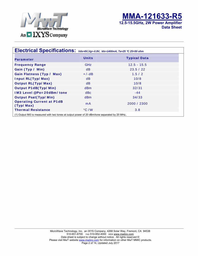
Electrical Specifications: Vds=6V,Vg=-0.9V, Ids=1400mA, Ta=25 °C Z0=50 ohm
Parameter Units Typical Data
Frequency Range GHz 12.5 - 15.5Gain (Typ / Min) dB 23.5 / 22Gain Flatness (Typ / Max) +/-dB 1.5 / 2Input RL(Typ/Max) dB 10/8Output RL(Typ/Max) dB 10/8 Output P1dB(Typ/Min) dBm 32/31IM3 Level @Po=20dBm/tone dBc -44Output Psat(Typ/Min) dBm 34/33Operating Current at P1dB (Typ/Max)
mA 2000 / 2300
Thermal Resistance °C /W 3.8(1) Output IM3 is measured with two tones at output power of 20 dBm/tone separated by 20 MHz.
MicroWave Technology, Inc. an IXYS Company, 4268 Solar Way, Fremont, CA 94538 510-651-6700 FAX 510-952-4000 WEB www.mwtinc.com
Data sheet is subject to change without notice. All rights reserved © Please visit MwT website www.mwtinc.com for information on other MwT MMIC products.
Page 2 of 14, Updated July 2017

MMA-121633-R5 12.5-15.5GHz, 2W Power Amplifier
Data Sheet
Typical RF Performance: Vds=6V, Vg=-0.9V, Ids=1400mA, Z0=50 ohm, Ta=25 ºC
8 9 10 11 12 13 14 15 16 17 18 19 20 21Frequency (GHz)
-20
-15
-10
-5
0
5
10
15
20
25
30
35
S11
, S21
, and
S22
(dB)
DB(|S(1,1)|)MEASDB(|S(2,1)|)MEASDB(|S(2,2)|)MEAS
S11[dB], S21[dB], and S22[dB] vs. Frequency
P-1 and Psat vs. Frequency
IM3 Level [dBc] vs. output power/tone [dBm]
Pout[dBm], and Ids[mA] vs. Input power [dBm]
MicroWave Technology, Inc. an IXYS Company, 4268 Solar Way, Fremont, CA 94538 510-651-6700 FAX 510-952-4000 WEB www.mwtinc.com
Data sheet is subject to change without notice. All rights reserved © Please visit MwT website www.mwtinc.com for information on other MwT MMIC products.
Page 3 of 14, Updated July 2017

MMA-121633-R5 12.5-15.5GHz, 2W Power Amplifier
Data Sheet
Typical Bias dependent RF Performance: Vds=4V
Bias dependent P1 vs. Frequency
Bias dependent P-3 vs. Frequency
@Vds=4V, Idsq=1400mA
@Vds=4V, Idsq=2000mA
8 9 10 11 12 13 14 15 16 17 18 19 20 21Frequency (GHz)
-20
-15
-10
-5
0
5
10
15
20
25
30
35
S11,
S21
, and
S22
(dB)
DB(|S(1,1)|)MEASDB(|S(2,1)|)MEASDB(|S(2,2)|)MEAS
Vds=4V, Ids=1400mA @Vds=4V, Idsq=2500mA
MicroWave Technology, Inc. an IXYS Company, 4268 Solar Way, Fremont, CA 94538 510-651-6700 FAX 510-952-4000 WEB www.mwtinc.com
Data sheet is subject to change without notice. All rights reserved © Please visit MwT website www.mwtinc.com for information on other MwT MMIC products.
Page 4 of 14, Updated July 2017

MMA-121633-R5 12.5-15.5GHz, 2W Power Amplifier
Data Sheet
Typical Bias dependent RF Performance: Vds=5V
Bias dependent P1 vs. Frequency
Bias dependent P-3 vs. Frequency
8 9 10 11 12 13 14 15 16 17 18 19 20 21Frequency (GHz)
-20
-15
-10
-5
0
5
10
15
20
25
30
35
S11,
S21
, and
S22
(dB)
DB(|S(1,1)|)MEASDB(|S(2,1)|)MEASDB(|S(2,2)|)MEAS
Vds=5V, Ids=1400mA
@Vds=5V, Idsq=1400mA
@Vds=5V, Idsq=2000mA
@Vds=5V, Idsq=2500mA
MicroWave Technology, Inc. an IXYS Company, 4268 Solar Way, Fremont, CA 94538 510-651-6700 FAX 510-952-4000 WEB www.mwtinc.com
Data sheet is subject to change without notice. All rights reserved © Please visit MwT website www.mwtinc.com for information on other MwT MMIC products.
Page 5 of 14, Updated July 2017

MMA-121633-R5 12.5-15.5GHz, 2W Power Amplifier
Data Sheet
Typical Bias dependent RF Performance: Vds=6V
Bias dependent P1 vs. Frequency
Bias dependent P-3 vs. Frequency
8 9 10 11 12 13 14 15 16 17 18 19 20 21Frequency (GHz)
-20
-15
-10
-5
0
5
10
15
20
25
30
35
S11
, S21
, and
S22
(dB
)
DB(|S(1,1)|)MEASDB(|S(2,1)|)MEASDB(|S(2,2)|)MEAS
Vds=6V, Ids=2000mA
@Vds=6V, Idsq=1400mA
@Vds=6V, Idsq=2000mA
@Vds=6V, Idsq=2500mA
MicroWave Technology, Inc. an IXYS Company, 4268 Solar Way, Fremont, CA 94538 510-651-6700 FAX 510-952-4000 WEB www.mwtinc.com
Data sheet is subject to change without notice. All rights reserved © Please visit MwT website www.mwtinc.com for information on other MwT MMIC products.
Page 6 of 14, Updated July 2017
MMA-121633-R5 12.5-15.5GHz, 2W Power Amplifier
Data Sheet
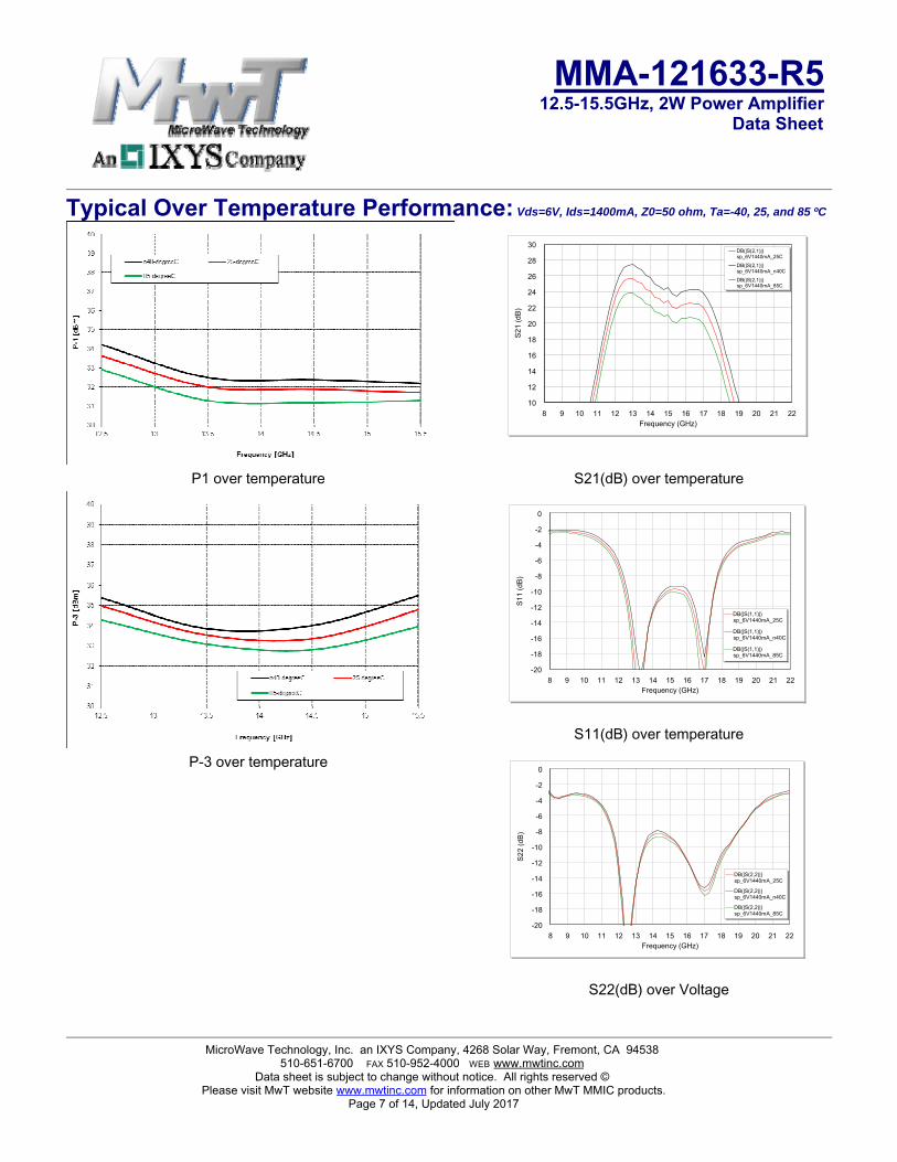
Typical Over Temperature Performance: Vds=6V, Ids=1400mA, Z0=50 ohm, Ta=-40, 25, and 85 ºC
8 9 10 11 12 13 14 15 16 17 18 19 20 21 22Frequency (GHz)
10
12
14
16
18
20
22
24
26
28
30
S21
(dB
)
DB(|S(2,1)|)sp_6V1440mA_25C
DB(|S(2,1)|)sp_6V1440mA_n40C
DB(|S(2,1)|)sp_6V1440mA_85C
P1 over temperature
P-3 over temperature
S21(dB) over temperature
8 9 10 11 12 13 14 15 16 17 18 19 20 21 22Frequency (GHz)
-20
-18
-16
-14
-12
-10
-8
-6
-4
-2
0S
11 (d
B)
DB(|S(1,1)|)sp_6V1440mA_25C
DB(|S(1,1)|)sp_6V1440mA_n40C
DB(|S(1,1)|)sp_6V1440mA_85C
S11(dB) over temperature
8 9 10 11 12 13 14 15 16 17 18 19 20 21 22Frequency (GHz)
-20
-18
-16
-14
-12
-10
-8
-6
-4
-2
0
S22
(dB
)
DB(|S(2,2)|)sp_6V1440mA_25C
DB(|S(2,2)|)sp_6V1440mA_n40C
DB(|S(2,2)|)sp_6V1440mA_85C
S22(dB) over Voltage
MicroWave Technology, Inc. an IXYS Company, 4268 Solar Way, Fremont, CA 94538 510-651-6700 FAX 510-952-4000 WEB www.mwtinc.com
Data sheet is subject to change without notice. All rights reserved © Please visit MwT website www.mwtinc.com for information on other MwT MMIC products.
Page 7 of 14, Updated July 2017

MMA-121633-R5 12.5-15.5GHz, 2W Power Amplifier
Data Sheet
Typical Power Detector Voltages: Vds=6V, Idsq=1.4A, Frequency=13GHz
Detector Voltages (DET_O and DET_R) vs. Output RF power
Vdelta axis is Log-scale.
+5V
DET_O
+5V
+
-
-5V
DET_R
10KΩ 10KΩ
10KΩ
10KΩ
100KΩ100KΩ
Vout=DET_R – DET_O
MicroWave Technology, Inc. an IXYS Company, 4268 Solar Way, Fremont, CA 94538 510-651-6700 FAX 510-952-4000 WEB www.mwtinc.com
Data sheet is subject to change without notice. All rights reserved © Please visit MwT website www.mwtinc.com for information on other MwT MMIC products.
Page 8 of 14, Updated July 2017

MMA-121633-R5 12.5-15.5GHz, 2W Power Amplifier
Data Sheet
Applications The MMA-121633-R5 MMIC power amplifier is designed for use as a power stage amplifier in
microwave transmitters. It is ideally suited for 12.7 to 15.4GHz band point to point radio applications requiring a flat gain response and excellent linearity performance. This amplifier is provided as a 5x5mm QFN package, and the packaged amplifier is fully compatible with industry standard high volume surface mount PCB assembly processes.
Biasing and Operation The recommended bias conditions for best performance for the MMA-121633-R5 are VDD = 6.0V,
Idsq = 1400mA. Performance improvements are possible depending on applications. The drain bias voltage range is 4 to 6V and the quiescent drain current biasing range is 1200mA to 2500mA. A single DC gate supply connected to Vg will bias all the amplifier stages. Muting can be accomplished by setting Vg to the pinch-off voltage (Vp=-2V). The gate voltage (Vg) should be applied prior to the drain voltages (Vd1, Vd2, and Vd3) during power up and removed after the drain voltages during power down. The RF input port is connected internally to the ground for ESD protection purpose; therefore, an input decoupling capacitor is needed if the preceding output stage has DC present. The RF output is DC decoupled internally. Typical DC supply connection with bi-passing capacitors for the MMA-121633-R5 is shown in following pages.
MMA-121633-R5 contains optional temperature compensated output power detectors. Typical detection voltage vs. output power is shown in previous page. To obtain over temperature compensation, a recommended differential amplifier is required.
Assembly Techniques GaAs MMICs are ESD sensitive. ESD preventive measures must be employed in all aspects of storage,
handling, and assembly. MMIC ESD precautions, handling considerations, die attach and bonding methods are critical factors in successful GaAs MMIC performance and reliability.
MicroWave Technology, Inc. an IXYS Company, 4268 Solar Way, Fremont, CA 94538 510-651-6700 FAX 510-952-4000 WEB www.mwtinc.com
Data sheet is subject to change without notice. All rights reserved © Please visit MwT website www.mwtinc.com for information on other MwT MMIC products.
Page 9 of 14, Updated July 2017

MMA-121633-R5 12.5-15.5GHz, 2W Power Amplifier
Data Sheet
Package Pin-out:
Pin Description4 RF Input21 RF Output10 Vg31 Vd128 Vd2
15, 26 Vd3 18 DET_Rreference23 DET_Output
1, 3, 5, 8 ,9, 16, 17, 20, 22, 24, 25, 32, 33
Ground
2, 6, 7, 11, 12, 13, 14, 19, 27, 29, 30
N/C
MicroWave Technology, Inc. an IXYS Company, 4268 Solar Way, Fremont, CA 94538 510-651-6700 FAX 510-952-4000 WEB www.mwtinc.com
Data sheet is subject to change without notice. All rights reserved © Please visit MwT website www.mwtinc.com for information on other MwT MMIC products.
Page 10 of 14, Updated July 2017

MMA-121633-R5 12.5-15.5GHz, 2W Power Amplifier
Data Sheet
Mechanical Information:
The units are in [mm].
MicroWave Technology, Inc. an IXYS Company, 4268 Solar Way, Fremont, CA 94538 510-651-6700 FAX 510-952-4000 WEB www.mwtinc.com
Data sheet is subject to change without notice. All rights reserved © Please visit MwT website www.mwtinc.com for information on other MwT MMIC products.
Page 11 of 14, Updated July 2017

MMA-121633-R5 12.5-15.5GHz, 2W Power Amplifier
Data Sheet
Application Circuit:
1
2
3
45
6
7
8
24
23
22
2120
19
18
17
9 10 11 12 13 14 15 16
32 31 30 29 28 27 26 25
GND
GND
GND
GND
RF IN RF OUT
RF Input
Vd1
Vd3Vg
RF Output
0.01u
10Ω
1uF
0.01u
10Ω
1uF
0.01u
10Ω
1uF
Vd2 Vd3
0.01u
10Ω
1uF0.01u
10Ω
0.01u
10Ω
1uF
DET_O
DET_R
Note:Vd3 pins must be biased
from both sides.
MicroWave Technology, Inc. an IXYS Company, 4268 Solar Way, Fremont, CA 94538 510-651-6700 FAX 510-952-4000 WEB www.mwtinc.com
Data sheet is subject to change without notice. All rights reserved © Please visit MwT website www.mwtinc.com for information on other MwT MMIC products.
Page 12 of 14, Updated July 2017

MMA-121633-R5 12.5-15.5GHz, 2W Power Amplifier
Data Sheet
Recommended Application Board Design: Board Material is 10mil (Dielectric) thickness Rogers 4350B with 0.5oz cupper clads. Board is soldered on a gold plated solid cupper block and adequate heat-sinking is required for 16.8W total power dissipation.
C1 C2
C4
C5
C7
C6
C9C10
R1
R2
R4R5
Vd2Vd1
Vd4Vg
RF IN RF OUT
Vd3
C3
R3 C8
DET_O
DET_R
Part DescriptionC1, C2, C3, C4, C5 1uF capacitor (0603)
C6, C7, C8, C9, C10 0.01uF Capacitor (0402) R1, R2, R3, R4, R5 10Ω Resistor (0402)
MicroWave Technology, Inc. an IXYS Company, 4268 Solar Way, Fremont, CA 94538 510-651-6700 FAX 510-952-4000 WEB www.mwtinc.com
Data sheet is subject to change without notice. All rights reserved © Please visit MwT website www.mwtinc.com for information on other MwT MMIC products.
Page 13 of 14, Updated July 2017

MMA-121633-R5 12.5-15.5GHz, 2W Power Amplifier
Data Sheet
Recommended Application Board Design: Board Material is 10mil (Dielectric) thickness Rogers 4350B with 0.5oz cupper clads. The board material and mounting pattern, as defined in the data sheet, optimizes RF performance and is strongly recommended. An electronic drawing of the land pattern is available upon request from MwT Sales & Application Engineering.
MicroWave Technology, Inc. an IXYS Company, 4268 Solar Way, Fremont, CA 94538 510-651-6700 FAX 510-952-4000 WEB www.mwtinc.com
Data sheet is subject to change without notice. All rights reserved © Please visit MwT website www.mwtinc.com for information on other MwT MMIC products.
Page 14 of 14, Updated July 2017