Embed Size (px)
Citation preview

w w w .edge-core .com
U s e r M a n u a l
Terragraph C lien t N ode
M LTG -C N / M LTG -C N LR

User Manual
MLTG-CNTerragraph-certified client node
MLTG-CN LRTerragraph-certified long-range client node
E122021-MR-R03
How to Use This Guide
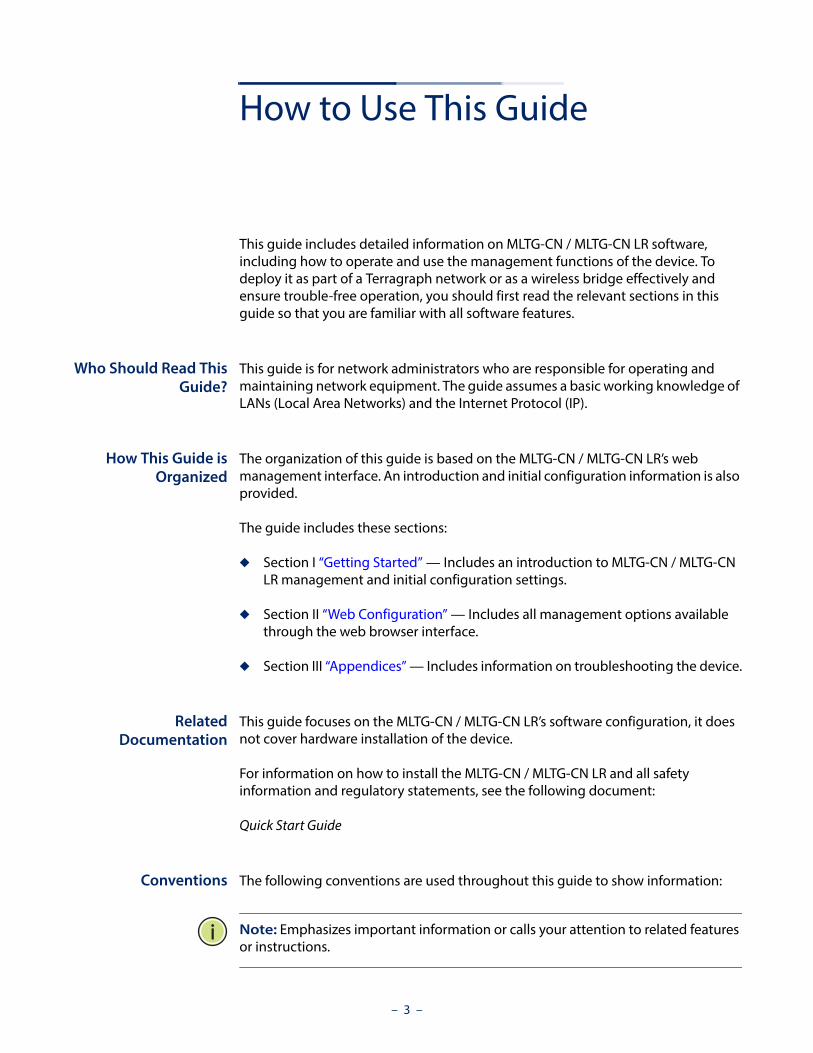
This guide includes detailed information on MLTG-CN / MLTG-CN LR software, including how to operate and use the management functions of the device. To deploy it as part of a Terragraph network or as a wireless bridge effectively and ensure trouble-free operation, you should first read the relevant sections in this guide so that you are familiar with all software features.
Who Should Read ThisGuide?
This guide is for network administrators who are responsible for operating and maintaining network equipment. The guide assumes a basic working knowledge of LANs (Local Area Networks) and the Internet Protocol (IP).
How This Guide isOrganized
The organization of this guide is based on the MLTG-CN / MLTG-CN LR’s web management interface. An introduction and initial configuration information is also provided.
The guide includes these sections:
◆ Section I “Getting Started” — Includes an introduction to MLTG-CN / MLTG-CN LR management and initial configuration settings.
◆ Section II “Web Configuration” — Includes all management options available through the web browser interface.
◆ Section III “Appendices” — Includes information on troubleshooting the device.
RelatedDocumentation
This guide focuses on the MLTG-CN / MLTG-CN LR’s software configuration, it does not cover hardware installation of the device.
For information on how to install the MLTG-CN / MLTG-CN LR and all safety information and regulatory statements, see the following document:
Quick Start Guide
Conventions The following conventions are used throughout this guide to show information:
Note: Emphasizes important information or calls your attention to related features or instructions.
– 3 –

How to Use This Guide
Caution: Alerts you to a potential hazard that could cause loss of data, or damage the system or equipment.
Warning: Alerts you to a potential hazard that could cause personal injury.
Contact If you have further questions, please submit a ticket at: https://support.edge-core.com/hc/en-us or send us an email: [email protected].
Revision History This section summarizes the changes in each revision of this guide.
December 2021 RevisionThis is the third version of this guide. This guide is valid for software release v1.2.0Added the long-range model, MLTG-CN LR.
July 2021 RevisionThis is the second version of this guide. This guide is valid for software release v1.1.1
March 2021 RevisionThis is the first version of this guide. This guide is valid for software release v1.0.1
– 4 –

Contents
How to Use This Guide 3
Contents 5
Figures 7
Tables 8
Section I Getting Started 9
1 Introduction 10
Terragraph Network 10
Connecting to the Web Interface 11
Section II Web Configuration 13
2 Status 14
Overview 14
Link Status 18
3 Network 19
Interfaces 19
Operation Mode 19
Link Configuration 22
4 System 23
System 23
General Settings 23
Logging 24
User Accounts 25
Maintenance 26
– 5 –

Contents
Services 29
SNMP 29
Diagnostics 30
Ping 30
Traceroute 30
Nslookup 31
Section III Appendices 32
A Specifications 33
Hardware Specifications 33
B Troubleshooting 35
Access and Operational Issues 35
Using System Logs 35
– 6 –

Figures
Figure 1: Example of a Terragraph Network 10
Figure 2: Login Page 12
Figure 3: Overview 14
Figure 4: System Overview 15
Figure 5: MAC Address Overview 15
Figure 6: Memory Overview 16
Figure 7: Operation Mode 16
Figure 8: Network Overview 17
Figure 9: Link Status 18
Figure 10: Operation Mode Settings 20
Figure 11: Link Configuration 22
Figure 12: General Settings 23
Figure 13: Logging 24
Figure 14: User Accounts 25
Figure 15: Maintenance 26
Figure 16: System Log 27
Figure 17: Restore Configuration Settings 28
Figure 18: Upgrade Firmware 28
Figure 19: Services 29
Figure 20: Diagnostics 30
Figure 21: Ping Result 30
Figure 22: Traceroute Result 31
Figure 23: Nslookup Result 31
– 7 –

Tables
Table 1: Logging Levels 25
Table 2: MLTG-CN Hardware Specifications 33
Table 3: MLTG-CN LR Hardware Specifications 34
Table 4: Troubleshooting Chart 35
– 8 –

Section I
Getting Started
This section provides an overview of the device, and introduces some basic concepts about Terragraph networks. It also describes the basic settings required to access the management interface.
This section includes these chapters:
◆ "Introduction" on page 10
– 9 –

1 Introduction
Terragraph NetworkTerragraph is a 60GHz, multi-node wireless Software Defined Network (SDN) that enables high-speed Internet connectivity in multiple environments. The network operates best in Line-Of-Sight (LOS) conditions to maximize connectivity.
Terragraph is a distribution level network designed to augment and expand a fiber optic network. That is, Terragraph is a high-speed backbone network to which other networks are connected. When combined with fixed access connections or Wi-Fi access points, Terragraph is a low-cost solution to achieve street-level coverage with high speeds.
A Terragraph network is composed of individual nodes. There are two types of nodes in a Terragraph network – Distribution Nodes (DNs), such as the MLTG-360 and Client Nodes (CNs), such as the MLTG-CN. DNs are the backbone of the Terragraph network that distribute Internet connectivity from one or more fiber optic Points of Presence (PoPs) over multiple hops to CNs. DNs and CNs are connection points for client networks, wireless access points, and other customer premise equipment (CPE) to connect to the Internet.
Figure 1: Example of a Terragraph Network
– 10 –

Chapter 1 | IntroductionConnecting to the Web Interface
Each node in a Terragraph network is a Layer 3 (L3) router. Nodes route traffic within and between the Terragraph network and attached access networks using routing information provided by the Open/R protocol. The over-the-air link protocol between Terragraph nodes uses a modified version of the Directed Multi-Gigabit (DMG) physical layer (PHY) of the IEEE 802.11ay standard.
Each node uses a multi-element, phased array antenna and advanced beamforming techniques to form high-quality communication links between nodes using primarily LOS paths while also using reflection paths.
Links can be formed at distances of up to 80 meters between two MLTG-CN nodes, and up to 150 meters between one MLTG-CN node and one MLTG-360 node. The MLTG-CN LR is suitable for long-range deployments as its range can reach up to 1500 meters when paired with one MLTG-CN LR, and up to 700 meters when paired with one MLTG-360.
The multiple propagation paths are called micro-routes, and each micro-route is a potential communication link between nodes. Each node selects the strongest communication link from the many possible propagation paths between the nodes. The phased array antenna allows Terragraph to establish links to mitigate co-channel interference that often prevails in dense urban environments.
The MLTG-CN / MLTG-CN LR is a node that serves as the termination point where service delivery takes place. It is not a part of the mesh network for distribution but provides connectivity to a fixed client such as a Wi-Fi Access point (AP) or a fixed connection to a home or office.
Connecting to the Web InterfaceThe MLTG-CN / MLTG-CN LR offers a user-friendly web-based management interface for the configuration of all the unit’s features. Any PC directly attached to the unit can access the management interface using a web browser, such as Internet Explorer 9.x or later, Mozilla Firefox 32 or later, and Google Chrome 35 or later.
The web interface is accessible via the LAN port or via the Management port (Uplink PoE). To access the web interface through the LAN port, follow these steps:
1. Connect a PC directly to the unit’s LAN port.
2. Set the PC IP address to be on the same subnet as the default IP address of the unit’s LAN port. The PC address must start 192.168.2.x with subnet mask 255.255.255.0).
3. Enter the default IP address of 192.168.2.1 into the web browser address bar.
– 11 –

Chapter 1 | IntroductionConnecting to the Web Interface
4. Log in to the web interface using default settings:
Username = adminPassword = admin
To access the web interface through the Management port (Uplink PoE), follow these steps:
1. Connect a PC to the data port of the injector powering the MLTG-CN / MLTG-CN LR.
2. The MLTG-CN / MLTG-CN LR is configured as a DHCP Client and will receive its IP dynamically. Check the DHCP Server on the PC for the assigned address. In case the DHCP server is unavailable, the device uses 192.168.1.20 and 255.255.255.0 as the fallback IP address and subnet mask, respectively.
3. Enter the IP address into the web browser address bar.
4. Log in to the web interface using default settings:
Username = adminPassword = admin
Figure 2: Login Page
– 12 –

Section II
Web Configuration
This section describes the basic switch features, along with a detailed description of how to configure each feature via a web browser.
This section includes these chapters:
◆ "Status" on page 14
◆ "System" on page 23
◆ "Network" on page 19
– 13 –

2 Status
OverviewAfter logging in to the web interface, the Overview screen is displayed. The Overview screen shows the basic settings of the device, including system information, memory and network status.
Figure 3: Overview
– 14 –

Chapter 2 | StatusOverview
The following items are displayed in this section:
◆ System
■ Hostname: The device name configured by the system automatically.
■ Device Name: The device name that can be configured manually.
■ Serial Number: The serial number of the unit.
■ Firmware Version: The software version number.
■ Local Time: The date and local time.
■ Uptime: The length of time the device has been up.
■ Load Average: The last 1-minute, 5-minute, and 15-minute CPU load average.
Figure 4: System Overview
◆ MAC Address
The complete list of MAC addresses of the device and the correspondent network interfaces: Management Port, LAN, and Radio
Figure 5: MAC Address Overview
– 15 –

Chapter 2 | StatusOverview
◆ Memory
The total available memory, how much memory is free, and how much memory is being used as buffer.
Figure 6: Memory Overview
◆ Operation Mode
■ Operation Mode: The current operation mode — Terragraph or Point-to-point.
■ Network Behavior: The behavior of the unit and of the entire Terragraph network. In Terragraph mode, the behavior is described as VXLAN Tunneling or Layer 2 Bridge. Point-to-point Mode is limited to Layer 2 Bridge.
Figure 7: Operation Mode
– 16 –

Chapter 2 | StatusOverview
◆ Network: Shows the IP information for each interface.
■ Management Port Status
■ LAN Status
■ Uplink Status
Figure 8: Network Overview
– 17 –

Chapter 2 | StatusLink Status
Link StatusFigure 9: Link Status
◆ Peer MAC: Radio MAC address of connected devices.
◆ RSSI: Received signal strength indication, this is an indicator of the received signal strength from the peer. Unit is decibels per milliwatt (dBm).
◆ MCS: Modulation and Coding Scheme (MCS) index values supported by the radio.
◆ Channel: The working channel.
◆ TX Power: The transmission power index. (Range: 6-31)
◆ PER: Packet error ratio. The ratio of error packets over received packets on this link.
◆ RX Beam Idx: Receiving beam index. The beamforming index that is used for receiving.
◆ TX Beam Idx: Transmitting beam index. The beamforming index that is used for transmission.
Note: Beam Idx 29 and 30 are the central-most beams. It is recommended to adjust the alignment to make beam indexes as central as possible.
– 18 –

3 Network
Interfaces
Operation Mode The MLTG-CN / MLTG-CN LR has two modes of operation, Terragraph Mode and Point-to-Point Mode.
When in Terragraph Mode, the MLTG-CN / MLTG-CN LR functions as a CPE device (Client node) providing last-mile, client-side Internet connectivity.
In Terragraph Mode, the MLTG-CN / MLTG-CN LR is triggered passively to set up a 60 GHz link association. The E2E controller (End-to-End controller), which is either embedded in the MLTG-360 or runs on the Terragraph Network Management System (TG NMS), triggers the establishment of all links in the defined Terragraph network. The MLTG-CN listens for the signal from the E2E controller to set up a link. Thus, users do not have to configure a link on the MLTG-CN.
After the link between the MLTG-CN / MLTG-CN LR and the POP node have been established, the POP node informs the CN of the network behavior.
If the POP node is in Terragraph Mode, every node behaves as an IPv6 router, and the VXLAN between CN and POP is set up automatically. The VXLAN tunnel can forward Layer 2 services (e.g. PPPoE, multicast streaming) over the Terragraph network. On the contrary, if the POP node is in Bridge Mode, each node behaves as a Layer 2 Bridge.
When the CN is in Point-to-Point mode, it also functions as a Layer 2 bridge. In this mode, the CN can setup a point-to-point link without the TG NMS or the local controller on the POP. Point-to-Point Mode supports VLAN transparent and is designed for point-to-point backhaul links.
Note: When in the same network as a MLTG-360 (DN), MLTG-CN/MLTG-CN LR must be in Terragraph mode.
– 19 –

Chapter 3 | NetworkInterfaces
Figure 10: Operation Mode Settings
Uplink Port Role◆ Role: Select the function of the Uplink Port (PoE port). It functions as a
dedicated management port by default. This role can be changed to LAN port.
LAN Settings◆ IP Address Mode: Configure the LAN interface to be in static IP mode or DHCP
mode. In DHCP mode, it broadcasts a DCHP request in the Layer 2 network when the network behavior is set to Layer 2 Bridge. When the network behavior is VXLAN, it sends a DHCP request to the core network via the VXLAN tunnel.
◆ Fallback IP: The IPv4 address used when a DHCP server is unavailable. Required when the IP Address Mode is DHCP.
◆ Fallback Netmask: The subnet mask used for the Fallback IP address. Required when the IP Address Mode is DHCP.
– 20 –
Chapter 3 | NetworkInterfaces
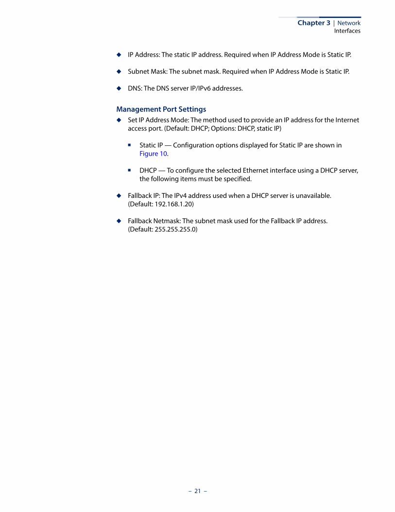
◆ IP Address: The static IP address. Required when IP Address Mode is Static IP.
◆ Subnet Mask: The subnet mask. Required when IP Address Mode is Static IP.
◆ DNS: The DNS server IP/IPv6 addresses.
Management Port Settings◆ Set IP Address Mode: The method used to provide an IP address for the Internet
access port. (Default: DHCP; Options: DHCP, static IP)
■ Static IP — Configuration options displayed for Static IP are shown in Figure 10.
■ DHCP — To configure the selected Ethernet interface using a DHCP server, the following items must be specified.
◆ Fallback IP: The IPv4 address used when a DHCP server is unavailable. (Default: 192.168.1.20)
◆ Fallback Netmask: The subnet mask used for the Fallback IP address. (Default: 255.255.255.0)
– 21 –

Chapter 3 | NetworkLink Configuration
Link ConfigurationThe MLTG-CN / MLTG-CN LR allows a point-to-point connection with another CN. Set up the link by selecting the working channel (1 to 4) and entering the 60GHz radio MAC address of the other MLTG-CN.
Figure 11: Link Configuration
Note: Link Configuration is only available when the operation mode is set to Point-to-Point Mode. You only need to configure a link on one of the two nodes.
– 22 –

4 System
System
General Settings Figure 12: General Settings
◆ Device Name: Configure the device name.
◆ Country: Select the installation region to automatically apply country-specific settings following local standards.
◆ NTP Server: Configure the NTP servers’ domain name or IP address.
◆ Timezone: Choose the appropriate time zone according to Continent/City.
◆ Number of boot retries for switching bootbank: The device has dual boot partitions. Set the number of power sequences before the device switches to the alternative boot bank. (Default: 5)
◆ Number of boot retries for factory reset: Set the number of power sequences that force a factory reset. (Default: 3)
– 23 –

Chapter 4 | SystemSystem
Note: To perform one power sequence plug in the PoE for 5 seconds and unplug it for 1 second. By default, two successive power sequences with complete boot on the third, triggers the factory reset. Four successive power sequences and a complete boot after that switches boot banks.
Logging Configure the remote system log server and log properties. Logs contain the configuration, link, and log information often needed to discover the root cause of a problem.
The device allows you to control the logging of error messages, including the type of events that are recorded and configure logging to a remote System Log (syslog) server or other management stations.
Figure 13: Logging
◆ System log buffer size: Specifies the available memory used for logging of error messages. (Default: 64 KiB)
◆ External system log server: Specifies the IPv4 or IPv6 address of a remote server which will be sent syslog messages.
◆ External system log server port: Specifies the UDP port number used by the remote server. (Range: 1-65535; Default: 514)
◆ Log output level: Use the menu to select the severity of the logs to print to the console. Logs with the severity level you select and all logs of greater severity print. For example, if you select Error, the logged messages include Error, Critical, Alert, and Emergency. The default severity level is Debug(7). The severity can be one of the following levels:
– 24 –
Chapter 4 | SystemUser Accounts
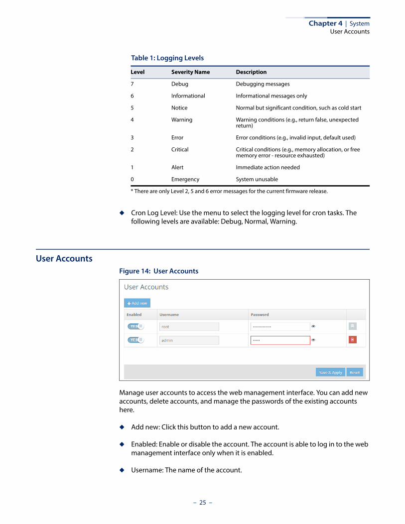
◆ Cron Log Level: Use the menu to select the logging level for cron tasks. The following levels are available: Debug, Normal, Warning.
User AccountsFigure 14: User Accounts
Manage user accounts to access the web management interface. You can add new accounts, delete accounts, and manage the passwords of the existing accounts here.
◆ Add new: Click this button to add a new account.
◆ Enabled: Enable or disable the account. The account is able to log in to the web management interface only when it is enabled.
◆ Username: The name of the account.
Table 1: Logging Levels
Level Severity Name Description
7 Debug Debugging messages
6 Informational Informational messages only
5 Notice Normal but significant condition, such as cold start
4 Warning Warning conditions (e.g., return false, unexpected return)
3 Error Error conditions (e.g., invalid input, default used)
2 Critical Critical conditions (e.g., memory allocation, or free memory error - resource exhausted)
1 Alert Immediate action needed
0 Emergency System unusable
* There are only Level 2, 5 and 6 error messages for the current firmware release.
– 25 –

Chapter 4 | SystemMaintenance
◆ Password: The password of the account. Click the eye symbol next to the input box to hide or show the clear text password. (ASCII characters, case sensitive)
◆ Delete: Click the trash can symbol to delete the corresponding account. Note that the “root” account cannot be deleted.
Maintenance Figure 15: Maintenance
◆ View Log: The device saves event and error messages to a local system log database. The log messages include the date and time, message type, and message details.
– 26 –
Chapter 4 | SystemMaintenance
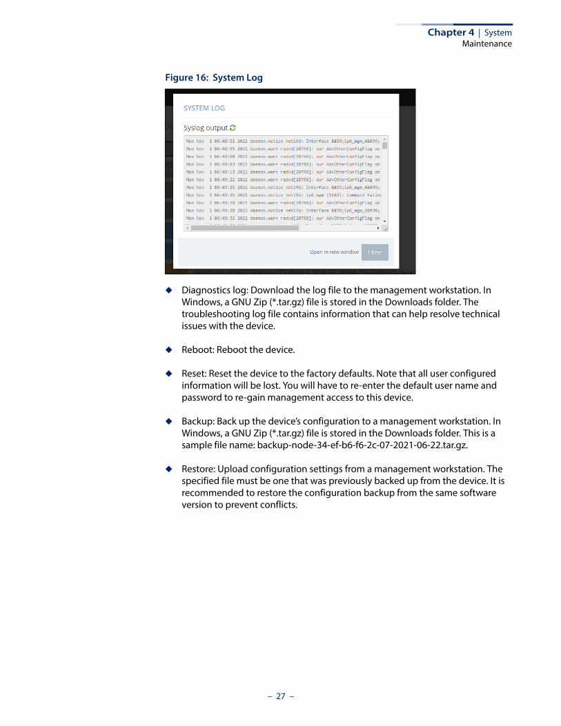
Figure 16: System Log
◆ Diagnostics log: Download the log file to the management workstation. In Windows, a GNU Zip (*.tar.gz) file is stored in the Downloads folder. The troubleshooting log file contains information that can help resolve technical issues with the device.
◆ Reboot: Reboot the device.
◆ Reset: Reset the device to the factory defaults. Note that all user configured information will be lost. You will have to re-enter the default user name and password to re-gain management access to this device.
◆ Backup: Back up the device’s configuration to a management workstation. In Windows, a GNU Zip (*.tar.gz) file is stored in the Downloads folder. This is a sample file name: backup-node-34-ef-b6-f6-2c-07-2021-06-22.tar.gz.
◆ Restore: Upload configuration settings from a management workstation. The specified file must be one that was previously backed up from the device. It is recommended to restore the configuration backup from the same software version to prevent conflicts.
– 27 –

Chapter 4 | SystemMaintenance
Figure 17: Restore Configuration Settings
◆ Upgrade: Upload and upgrade new software from a local file on the management workstation. New software may be provided periodically by Edgecore.
After upgrading new software, you must reboot the device to implement the new code. Until a reboot occurs, the device will continue to run the software it was using before the upgrade started. The device supports dual software images, so if newly loaded software is corrupted, the alternate image will be used on the next reboot.
■ Keep current settings after upgrade: Enable this option to keep settings after upgrade. When this option is disabled, it will reset to factory default after upgrade.
Figure 18: Upgrade Firmware
– 28 –

Chapter 4 | SystemServices
ServicesFigure 19: Services
SNMP The Simple Network Management Protocol (SNMP) is designed specifically for managing devices on a network. It is typically used to configure devices for proper operation in a network environment, as well as to monitor them to evaluate performance or detect potential problems.
The MLTG-CN / MLTG-CN LR supports SNMP v2 and v3. It can be monitored through standard MIBs, such as MIB-II, UCD MIB, and a private MIB for link status.
◆ SNMP Server: Enables or disables SNMP on the unit.
◆ Write Community: A community string that acts like a password and permits access through SNMP protocol version 2. This community string verifies the access of IPv4 users.
◆ IPv6 Write Community: This community string verifies the access of IPv6 users.
◆ SNMP V3 Users: SNMP protocol version 3 provides secure access by account authentication and data encryption. The SNMP v3 user list can be defined with the following items.
■ Name: The user name used to access the SNMP service.
■ Access Auth.: Select the access permission as “Read Only” or “Write.”
– 29 –

Chapter 4 | SystemDiagnostics
■ Auth. Type: Select the hash algorithm for authentication.
■ Auth. Pwd.: Configure the password for authentication.
■ Encryption Type: Select the encryption algorithm for data packets.
■ Encryption Pwd: Configure the password for data encryption.
Note: SNMP configuration is only available in Point-to-point mode. In Terragraph mode, the SNMP is configured on the E2E controller. When using the local controller on the POP, the network synchronizes the SNMP settings with the POP node.
DiagnosticsThe Diagnostics page provides Ping, Traceroute, and Nslookup tools for troubleshooting connectivity problems. Enter a hostname or IP address, specify if it is an IPv4 or IPv6 address, and click to run the tool.
Figure 20: Diagnostics
Ping Input either an IP address or URL and click the PING button. A successful PING output will be as in Figure 21.
Figure 21: Ping Result
Traceroute Input either an IP address or URL and click the Traceroute button. The traceroute output will be as in Figure 22.
– 30 –

Chapter 4 | SystemDiagnostics
Figure 22: Traceroute Result
Nslookup Input either an IP address or URL and click the Nslookup button. The output of the Nslookup will be as in Figure 23.
Figure 23: Nslookup Result
– 31 –

Section III
Appendices
This section provides additional information and includes these items:
◆ “Specifications” on page 33
◆ “Troubleshooting” on page 35
– 32 –

A Specifications
Hardware Specifications
1 RF output power in this context means EIRP with antenna gain.2 Maximum power is limited by local regulatory requirements.
Table 2: MLTG-CN Hardware Specifications
Physical
Power 48~55V Passive Gigabit PoE
Dimensions (L x W x H) 177.3 x 111.6 x 43 mm (6.98 x 4.39 x 1.69 in)
Weight 518 g (1.14 lb)
Interfaces 1 x Gigabit Ethernet Port (PoE IN)1 x Gigiabit Ethernet Port1 x 60 GHz Radio
Environmental Conditions Operating Temperature: -20° C to 55° C (-4° F to 131° F)Storage Temperature: -20° C to 70° C (-4° F to 158° F)Operating Humidity: 5% to 95% non-condensingIP66 RatingWind Resistance: 208 km/h
Power Consumption 24 W max.
Antenna Type: Built-in phased array antennaGain: 22 dBi
Certifications FCC/CE/IC/VCCI/TELEC/RCM
Radio
Standards 802.11ay
60 GHz Phased array antenna with 64 antenna elements90 degrees azimuth scan range: -45° to 45°50 degrees elevation scan range: -25° to 25°
RF Output Power*1 Up to 38 dBm*2
Frequency Band 57-66 GHz
Modulation BPSK, QPSK, 16QAM
Performance
Range When connected to an MLTG-360:◆ Up to 100 m (0.06 mi) for MCS12◆ Up to 150 (0.09 mi) for MSCS9When connected to an MLTG-CN:◆ Up to 80m (0.05 mi) for MCS9
– 33 –

Appendix A | SpecificationsHardware Specifications
1 RF output power in this context means EIRP with antenna gain.2 Maximum power is limited by local regulatory requirements.
Table 3: MLTG-CN LR Hardware Specifications
Physical
Power 24~57V Passive PoE injector (DC terminal block)
Dimensions (L x W x H) 355 x 355 x 315 mm (13.98 x 13.98 x 12.40 in)
Weight 3 kg (6.61 lb)
Interfaces 1 x 2.5G Ethernet Port (PoE IN)1 x SFP Port1 x 60 GHz Radio
Environmental Conditions Operating Temperature: -40° C to 60° C (-40° F to 140° F)Storage Temperature: -40° C to 70° C (-40° F to 158° F)Operating Humidity: 5% to 95% non-condensingIP66 RatingWind Resistance: 210 km/h (sustained wind)/ 265 km/h (wind gust)
Power Consumption 15.9 W max.
Antenna Type: Built-in phased array antenna with dishGain: 40 dBiScan Range: +/-3°Beam Width: 1°
Mounting Wall/Pole mount (Mounting kit included)
Certifications FCC/CE/IC/VCCI/TELEC
Radio
Standards 802.11ay
RF Output Power*1 Up to 56 dBm*2
Frequency Band 57-66 GHz (channel 1 to 4)
Channel Bandwidth 2160MHz4320MHz (available in future software release)
Modulation BPSK, QPSK, 16QAM
Performance
Range When connected to an MLTG-360:◆ Up to 700 m (0.43 mi)When connected to an MLTG-CN LR:◆ Up to 1500 m (0.93 mi)
Throughput 3.5 Gbps aggregated
– 34 –

B Troubleshooting
Access and Operational Issues
Using System LogsIf a fault does occur, refer to the Quick Start Guide to ensure that the problem you encountered is actually caused by this device. If the problem appears to be caused by the MLTG-CN, follow these steps:
1. Repeat the sequence of commands or other actions that lead up to the error.
2. Make a list of the commands or circumstances that led to the fault. Also make a list of any error messages displayed.
Table 4: Troubleshooting Chart
Symptom Action
No Network Connection If there is a wired/wireless connection, but no network connection available through the link:◆ Verify that the computers or devices used to test the connection
are correctly configured.◆ Verify that the network interfaces are enabled.◆ Verify that the MTU size is set correctly for the L2 network.◆ Use diagnostic tools and packet captures between various devices
to find where the connection fails.
Cannot connect using web browser
◆ Be sure the MLTG-CN is powered up.◆ Check network cabling between the management station and the
wireless bridge.◆ Check that you have a valid network connection to the MLTG-CN
and that intermediate switch ports have not been disabled.◆ Be sure you have configured the MLTG-CN with a valid IP address,
subnet mask and default gateway.◆ Be sure the management station has an IP address in the same
subnet as the MLTG-CN’s IP.◆ If you are trying to connect to the MLTG-CN using a tagged VLAN
group, your management station, and the ports connecting intermediate switches in the network, must be configured with the appropriate tag.
Forgot or lost the password ◆ Reset the device to factory defaults using the power sequence described underu “Number of boot retries for factory reset: Set the number of power sequences that force a factory reset. (Default: 3)”.
– 35 –

Appendix B | TroubleshootingUsing System Logs
3. Record all relevant system settings.
4. Display the log file from the System > Maintenance page, and copy the information from the log file.
5. Download the Diagnostics Log to a file from the System > Maintenance page.
6. Contact your distributor’s service engineer, and send a detailed description of the problem, along with all of the information mentioned in the above steps.
– 36 –

MLTG-CNE122021-MR-R03