Embed Size (px)
Citation preview

User’s Manual
Extron Electronics, USA1230 South Lewis StreetAnaheim, CA 92805800.633.9876 714.491.1500 FAX 714.491.1517
Extron Electronics, EuropeBeeldschermweg 6C3821 AH Amersfoort, The Netherlands+800.3987.6673 +31.33.453.4040FAX +31.33.453.4050
Extron Electronics, Asia135 Joo Seng Rd. #04-01PM Industrial Bldg., Singapore 368363+800.7339.8766 +65.6383.4400 FAX +65.6383.4664
Extron Electronics, JapanKyodo Building, 16 IchibanchoChiyoda-ku, Tokyo 102-0082Japan+81.3.3511.7655 FAX +81.3.3511.7656www.extron.com
© 2007 Extron Electronics. All rights reserved.
Remote Control Panels
68-1069-01 Rev. C04 07
MKP 3000 Series

Precautions
This symbol is intended to alert the user of importantoperating and maintenance (servicing) instructionsin the literature provided with the equipment.
This symbol is intended to alert the user of thepresence of uninsulated dangerous voltage withinthe product's enclosure that may present a risk ofelectric shock.
CautionRead Instructions • Read and understand all safety and operating
instructions before using the equipment.Retain Instructions • The safety instructions should be kept for future
reference.Follow Warnings • Follow all warnings and instructions marked on the
equipment or in the user information.Avoid Attachments • Do not use tools or attachments that are not
recommended by the equipment manufacturer because they may behazardous.
WarningPower sources • This equipment should be operated only from the power source
indicated on the product. This equipment is intended to be used with a mainpower system with a grounded (neutral) conductor. The third (grounding) pin isa safety feature, do not attempt to bypass or disable it.
Power disconnection • To remove power from the equipment safely, remove allpower cords from the rear of the equipment, or the desktop power module (ifdetachable), or from the power source receptacle (wall plug).
Power cord protection • Power cords should be routed so that they are not likely tobe stepped on or pinched by items placed upon or against them.
Servicing • Refer all servicing to qualified service personnel. There are no user-serviceable parts inside. To prevent the risk of shock, do not attempt to servicethis equipment yourself because opening or removing covers may expose you todangerous voltage or other hazards.
Slots and openings • If the equipment has slots or holes in the enclosure, these areprovided to prevent overheating of sensitive components inside. These openingsmust never be blocked by other objects.
Lithium battery • There is a danger of explosion if battery is incorrectly replaced.Replace it only with the same or equivalent type recommended by themanufacturer. Dispose of used batteries according to the manufacturer'sinstructions.
Ce symbole sert à avertir l’utilisateur que ladocumentation fournie avec le matériel contient desinstructions importantes concernant l’exploitationet la maintenance (réparation).
Ce symbole sert à avertir l’utilisateur de la présencedans le boîtier de l’appareil de tensions dangereusesnon isolées posant des risques d’électrocution.
AttentionLire les instructions• Prendre connaissance de toutes les consignes de
sécurité et d’exploitation avant d’utiliser le matériel.Conserver les instructions• Ranger les consignes de sécurité afin de
pouvoir les consulter à l’avenir.Respecter les avertissements • Observer tous les avertissements et
consignes marqués sur le matériel ou présentés dans la documentationutilisateur.
Eviter les pièces de fixation • Ne pas utiliser de pièces de fixation nid’outils non recommandés par le fabricant du matériel car celarisquerait de poser certains dangers.
AvertissementAlimentations• Ne faire fonctionner ce matériel qu’avec la source d’alimentation
indiquée sur l’appareil. Ce matériel doit être utilisé avec une alimentationprincipale comportant un fil de terre (neutre). Le troisième contact (de mise à laterre) constitue un dispositif de sécurité : n’essayez pas de la contourner ni de ladésactiver.
Déconnexion de l’alimentation• Pour mettre le matériel hors tension sans danger,déconnectez tous les cordons d’alimentation de l’arrière de l’appareil ou dumodule d’alimentation de bureau (s’il est amovible) ou encore de la prise secteur.
Protection du cordon d’alimentation • Acheminer les cordons d’alimentation demanière à ce que personne ne risque de marcher dessus et à ce qu’ils ne soientpas écrasés ou pincés par des objets.
Réparation-maintenance • Faire exécuter toutes les interventions de réparation-maintenance par un technicien qualifié. Aucun des éléments internes ne peut êtreréparé par l’utilisateur. Afin d’éviter tout danger d’électrocution, l’utilisateur nedoit pas essayer de procéder lui-même à ces opérations car l’ouverture ou leretrait des couvercles risquent de l’exposer à de hautes tensions et autres dangers.
Fentes et orifices • Si le boîtier de l’appareil comporte des fentes ou des orifices,ceux-ci servent à empêcher les composants internes sensibles de surchauffer. Cesouvertures ne doivent jamais être bloquées par des objets.
Lithium Batterie • Il a danger d'explosion s'll y a remplacment incorrect de labatterie. Remplacer uniquement avec une batterie du meme type ou d'un ypeequivalent recommande par le constructeur. Mettre au reut les batteries usageesconformement aux instructions du fabricant.
Safety Instructions • English
Consignes de Sécurité • Français
Sicherheitsanleitungen • DeutschDieses Symbol soll dem Benutzer in der imLieferumfang enthaltenen Dokumentationbesonders wichtige Hinweise zur Bedienung undWartung (Instandhaltung) geben.
Dieses Symbol soll den Benutzer darauf aufmerksammachen, daß im Inneren des Gehäuses diesesProduktes gefährliche Spannungen, die nicht isoliertsind und die einen elektrischen Schock verursachenkönnen, herrschen.
AchtungLesen der Anleitungen • Bevor Sie das Gerät zum ersten Mal verwenden,
sollten Sie alle Sicherheits-und Bedienungsanleitungen genaudurchlesen und verstehen.
Aufbewahren der Anleitungen • Die Hinweise zur elektrischen Sicherheitdes Produktes sollten Sie aufbewahren, damit Sie im Bedarfsfall daraufzurückgreifen können.
Befolgen der Warnhinweise • Befolgen Sie alle Warnhinweise undAnleitungen auf dem Gerät oder in der Benutzerdokumentation.
Keine Zusatzgeräte • Verwenden Sie keine Werkzeuge oder Zusatzgeräte,die nicht ausdrücklich vom Hersteller empfohlen wurden, da diese eineGefahrenquelle darstellen können.
VorsichtStromquellen • Dieses Gerät sollte nur über die auf dem Produkt angegebene
Stromquelle betrieben werden. Dieses Gerät wurde für eine Verwendung miteiner Hauptstromleitung mit einem geerdeten (neutralen) Leiter konzipiert. Derdritte Kontakt ist für einen Erdanschluß, und stellt eine Sicherheitsfunktion dar.Diese sollte nicht umgangen oder außer Betrieb gesetzt werden.
Stromunterbrechung • Um das Gerät auf sichere Weise vom Netz zu trennen,sollten Sie alle Netzkabel aus der Rückseite des Gerätes, aus der externenStomversorgung (falls dies möglich ist) oder aus der Wandsteckdose ziehen.
Schutz des Netzkabels • Netzkabel sollten stets so verlegt werden, daß sie nichtim Weg liegen und niemand darauf treten kann oder Objekte darauf- oderunmittelbar dagegengestellt werden können.
Wartung • Alle Wartungsmaßnahmen sollten nur von qualifiziertemServicepersonal durchgeführt werden. Die internen Komponenten des Gerätessind wartungsfrei. Zur Vermeidung eines elektrischen Schocks versuchen Sie inkeinem Fall, dieses Gerät selbst öffnen, da beim Entfernen der Abdeckungen dieGefahr eines elektrischen Schlags und/oder andere Gefahren bestehen.
Schlitze und Öffnungen • Wenn das Gerät Schlitze oder Löcher im Gehäuseaufweist, dienen diese zur Vermeidung einer Überhitzung der empfindlichenTeile im Inneren. Diese Öffnungen dürfen niemals von anderen Objektenblockiert werden.
Litium-Batterie • Explosionsgefahr, falls die Batterie nicht richtig ersetzt wird.Ersetzen Sie verbrauchte Batterien nur durch den gleichen oder einenvergleichbaren Batterietyp, der auch vom Hersteller empfohlen wird. EntsorgenSie verbrauchte Batterien bitte gemäß den Herstelleranweisungen.
Este símbolo se utiliza para advertir al usuario sobreinstrucciones importantes de operación ymantenimiento (o cambio de partes) que se deseandestacar en el contenido de la documentaciónsuministrada con los equipos.
Este símbolo se utiliza para advertir al usuario sobrela presencia de elementos con voltaje peligroso sinprotección aislante, que puedan encontrarse dentrode la caja o alojamiento del producto, y que puedanrepresentar riesgo de electrocución.
PrecaucionLeer las instrucciones • Leer y analizar todas las instrucciones de
operación y seguridad, antes de usar el equipo.Conservar las instrucciones • Conservar las instrucciones de seguridad
para futura consulta.Obedecer las advertencias • Todas las advertencias e instrucciones
marcadas en el equipo o en la documentación del usuario, deben serobedecidas.
Evitar el uso de accesorios • No usar herramientas o accesorios que nosean especificamente recomendados por el fabricante, ya que podrianimplicar riesgos.
AdvertenciaAlimentación eléctrica • Este equipo debe conectarse únicamente a la fuente/tipo
de alimentación eléctrica indicada en el mismo. La alimentación eléctrica de esteequipo debe provenir de un sistema de distribución general con conductorneutro a tierra. La tercera pata (puesta a tierra) es una medida de seguridad, nopuentearia ni eliminaria.
Desconexión de alimentación eléctrica • Para desconectar con seguridad laacometida de alimentación eléctrica al equipo, desenchufar todos los cables dealimentación en el panel trasero del equipo, o desenchufar el módulo dealimentación (si fuera independiente), o desenchufar el cable del receptáculo dela pared.
Protección del cables de alimentación • Los cables de alimentación eléctrica sedeben instalar en lugares donde no sean pisados ni apretados por objetos que sepuedan apoyar sobre ellos.
Reparaciones/mantenimiento • Solicitar siempre los servicios técnicos de personalcalificado. En el interior no hay partes a las que el usuario deba acceder. Paraevitar riesgo de electrocución, no intentar personalmente la reparación/mantenimiento de este equipo, ya que al abrir o extraer las tapas puede quedarexpuesto a voltajes peligrosos u otros riesgos.
Ranuras y aberturas • Si el equipo posee ranuras o orificios en su caja/alojamiento,es para evitar el sobrecalientamiento de componentes internos sensibles. Estasaberturas nunca se deben obstruir con otros objetos.
Batería de litio • Existe riesgo de explosión si esta batería se coloca en la posiciónincorrecta. Cambiar esta batería únicamente con el mismo tipo (o su equivalente)recomendado por el fabricante. Desachar las baterías usadas siguiendo lasinstrucciones del fabricante.
Instrucciones de seguridad • Español
Extron’s WarrantyExtron Electronics warrants this product against defects in materials andworkmanship for a period of three years from the date of purchase. In the event ofmalfunction during the warranty period attributable directly to faulty workmanshipand/or materials, Extron Electronics will, at its option, repair or replace said productsor components, to whatever extent it shall deem necessary to restore said product toproper operating condition, provided that it is returned within the warranty period,with proof of purchase and description of malfunction to:
USA, Canada, South America, Europe, Africa, and the Middle East:and Central America: Extron Electronics, EuropeExtron Electronics Beeldschermweg 6C1001 East Ball Road 3821 AH AmersfoortAnaheim, CA 92805, USA The Netherlands
Asia: Japan:Extron Electronics, Asia Extron Electronics, Japan135 Joo Seng Road, #04-01 Kyodo BuildingPM Industrial Bldg. 16 IchibanchoSingapore 368363 Chiyoda-ku, Tokyo 102-0082
Japan
This Limited Warranty does not apply if the fault has been caused by misuse,improper handling care, electrical or mechanical abuse, abnormal operating conditionsor non-Extron authorized modification to the product.
If it has been determined that the product is defective, please call Extron and ask for anApplications Engineer at (714) 491-1500 (USA), 31.33.453.4040 (Europe), 65.6383.4400(Asia), or 81.3.3511.7655 (Japan) to receive an RA# (Return Authorization number). Thiswill begin the repair process as quickly as possible.
Units must be returned insured, with shipping charges prepaid. If not insured, youassume the risk of loss or damage during shipment. Returned units must include theserial number and a description of the problem, as well as the name of the person tocontact in case there are any questions.
Extron Electronics makes no further warranties either expressed or implied withrespect to the product and its quality, performance, merchantability, or fitness for anyparticular use. In no event will Extron Electronics be liable for direct, indirect, orconsequential damages resulting from any defect in this product even if ExtronElectronics has been advised of such damage.
Please note that laws vary from state to state and country to country, and that someprovisions of this warranty may not apply to you.
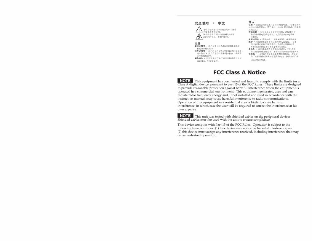
FCC Class A Notice This equipment has been tested and found to comply with the limits for a
Class A digital device, pursuant to part 15 of the FCC Rules. These limits are designedto provide reasonable protection against harmful interference when the equipment isoperated in a commercial environment. This equipment generates, uses and canradiate radio frequency energy and, if not installed and used in accordance with theinstruction manual, may cause harmful interference to radio communications.Operation of this equipment in a residential area is likely to cause harmfulinterference, in which case the user will be required to correct the interference at hisown expense.
This unit was tested with shielded cables on the peripheral devices.Shielded cables must be used with the unit to ensure compliance.
This device complies with Part 15 of the FCC Rules. Operation is subject to thefollowing two conditions: (1) this device may not cause harmful interference, and(2) this device must accept any interference received, including interference that maycause undesired operation.

Precautions, cont’d
MKP 3000 Series • Quick Start Guide
Quick Start Guide — MKP 3000
QS-1
Install and set up the MKP 3000 as follows:
Step 1Turn all of the equipment off or disconnect it from its power source.
Step 2Install the cables that will run to and from the control panel in awall, podium, or desk.
Step 3Prepare the wall, podium, desk, or other surface to mount the MKP.See “Preparing the site and installing the mounting bracket (mudring) or wall box” in chapter 2, “Installation.”
Step 4Install the control panel in a wall, podium, desk, or other surface.See “Installation Procedures” in chapter 2, “Installation.”
Step 5Connect the input and output cables. See “Rear Panel and SidePanel Connections” in chapter 2, “Installation,” for guidelines.
Step 6Connect the power supply. See “Power supply wiring” in chapter 2,“Installation.”
Step 7Connect power cords and turn on the equipment in the followingorder: output devices (such as projectors or monitors), the connectedmatrix switcher, and input devices (such as DSSs or cable boxes).
Step 8If necessary, set the IP parameters of the control panel and matrixswitcher. See “Viewing and configuring the IP and MKP setupparameters” in chapter 3, “Local Operation;” or “System Settingspage” in chapter 5, “HTML Operation.”
Step 9If necessary, set the control panel’s RS-232 port for pass-through orno-pass-through mode, and specify whether the MKP is the primarydevice (connected to the switcher) or secondary device (connectedthrough another device). See “Viewing and configuring the IP andMKP setup parameters” in chapter 3, “Local Operation,” or “SystemSettings page” in chapter 5, “HTML Operation.”

MKP 3000 Series • Quick Start Guide
Quick Start Guide — MKP 3000, cont’d
iMKP 3000 Series • Table of Contents
Chapter 1 • Introduction .......................................................... 1-1
About this Manual ................................................................ 1-2
About the MKP 3000 Series Remote ControlPanels ........................................................................................... 1-2
Setup examples ...................................................................... 1-3RS-232 connection to the switcher ....................................... 1-4Ethernet connection to the switcher ................................... 1-4Application diagram.............................................................. 1-4
Chapter 2 • Installation ............................................................. 2-1
MKP Installation Overview ............................................... 2-2
Installation Procedures ....................................................... 2-3Preparing the site .................................................................. 2-3UL requirements for wall box installation ........................... 2-4Installing a mounting bracket (mud ring) or wall box ........ 2-4Mounting the MKP to a mud ring or wall box .................... 2-7Mounting the MKP 3000 L .................................................... 2-8
Mounting the MKP 3000 L in a lectern .......................... 2-8Mounting the MKP 3000 L in a rack ............................... 2-8UL requirements for rack mounting ............................... 2-9
Rear Panel and Side Panel Connections .................. 2-10Control connections ............................................................ 2-13
RS-232 connection ......................................................... 2-13RS-232 cable termination .............................................. 2-14Ethernet connection ...................................................... 2-15Ethernet (TP) cable termination ................................... 2-16
Power supply wiring ............................................................ 2-18
Mounting the MKP 10 MAAP ......................................... 2-19
Chapter 3 • Local Operation .................................................. 3-1
Front Panel Controls and Indications ......................... 3-2
Front Panel Operations ....................................................... 3-4Changing the tie mode ......................................................... 3-4Creating ties ........................................................................... 3-5
Creating a tie in matrix mode (default) ......................... 3-5Creating a tie in input-only mode .................................. 3-7Deselecting a tie .............................................................. 3-8
Viewing ties ........................................................................... 3-9Selecting a preset ................................................................ 3-10Adjusting the audio output ................................................ 3-10
Table of Contents
QS-2
Step 10Program the control panel with the size of the connected switcher.See “System Settings page” in chapter 5, “HTML Operation.”
Step 11Use the control panel to select inputs and outputs. See “Front PanelOperations” in chapter 3, “Local Operation.”

iMKP 3000 Series • Table of Contentsii MKP 3000 Series • Table of Contents
Table of Contents, cont’d
Switcher Control Settings section ................................... 5-7MKP Connection Priority settings ............................. 5-7Host Control Port settings ......................................... 5-8Switcher Size settings ................................................ 5-8Switcher IP settings/Primary MKP settings ............... 5-8Authorized Inputs and Authorized Outputssettings ....................................................................... 5-9Front Panel Configuration Lock settings .................. 5-9Switching method radio buttons .............................. 5-9Save/restore configuration buttons .......................... 5-9
Date/Time Settings fields ............................................... 5-10Port (RS-232) Settings page ................................................. 5-11Passwords page .................................................................... 5-12
Assigning a password .................................................... 5-12Clearing a password ...................................................... 5-13
Input/Output Names page .................................................. 5-13Preset Names page .............................................................. 5-14Firmware Upgrade page ..................................................... 5-16
Updating the firmware using a direct computer-to-MKP connection ............................................................. 5-18
Using the File Management Page ............................... 5-20Uploading files ..................................................................... 5-20Adding a directory ............................................................... 5-21Other file management activities ....................................... 5-21
Saving and Restoring a Configuration .................... 5-21Saving a configuration ........................................................ 5-21Restoring a configuration ................................................... 5-23
Special Characters ............................................................... 5-24
Appendix A • Reference Information ............................ A-1
Specifications ......................................................................... A-2
Part Numbers .......................................................................... A-4Included parts ....................................................................... A-4Installation accessories ......................................................... A-4Cables .................................................................................... A-5Optional accessories ............................................................. A-5
Mounting and Cabling Specifications ....................... A-6Electrical box cutout ............................................................. A-6Panel mount cutout templates ............................................ A-6Extron Comm-Link Control System cable ............................ A-9
Changing Button Labels .................................................... A-9
iii
Viewing and configuring the IP and MKP setupparameters ........................................................................... 3-11
Host control port setting and pass-throughcommunications ............................................................. 3-13
Setting the LCD window backlighting ............................... 3-14Setup procedures diagram .................................................. 3-14Control panel security lockout (executive mode) .............. 3-16
Resets from the Rear Panel ............................................ 3-17Performing soft resets ......................................................... 3-17Performing a hard reset ...................................................... 3-19
MKP 10 MAAP and MKP 3000 L KeypadOperation ................................................................................. 3-20
Chapter 4 • SIS™ Operation ..................................................... 4-1
RS-232 Links .............................................................................. 4-2Routing matrix switcher commands ..................................... 4-2
Ethernet Link ........................................................................... 4-2Default IP address .................................................................. 4-3
Host-to-MKP Instructions .................................................. 4-3
MKP-Initiated (Unsolicited) Messages ........................ 4-3
MKP Error Responses ........................................................... 4-4
Using the Command/Response Table .......................... 4-5Symbol definitions ................................................................. 4-6Command/Response table for MKP SIS commands ............. 4-9
Chapter 5 • HTML Operation .................................................. 5-1
Downloading the Startup Page ..................................... 5-2
Viewing System Status ....................................................... 5-4
Using the Configuration Pages ...................................... 5-5System Settings page............................................................. 5-5
IP Settings section ............................................................ 5-6Unit Name field .......................................................... 5-6DHCP radio buttons ................................................... 5-6IP Address field ........................................................... 5-6Gateway IP Address field ........................................... 5-6Subnet Mask field ...................................................... 5-7MAC Address field ..................................................... 5-7Firmware field ............................................................ 5-7Model field ................................................................. 5-7Part Number field ...................................................... 5-7

ii MKP 3000 Series • Table of Contents
Table of Contents, cont’d
MKP 3000 Series
1Chapter One
Introduction
About this Manual
About the MKP 3000 Series Remote Control Panels
iv
68-1069-01 C04 07
All trademarks mentioned in this manual are the properties of their respective owners.

MKP 3000 Series • IntroductionMKP 3000 Series • Introduction
Introduction
1-3
Setup examplesThe matrix switcher system can have up to 128 inputs and 128outputs. However, for example, a conference room may havethree input devices and two output devices, a training roomnext door may have four input devices and one output device,and so on. Typically, each room has one or more MKP controlpanels assigned to it, with each MKP limited to the inputs andoutputs that it can control.
In the example in figure 1-1, the “presentation room” (top,center) has one output device, a projector (C), and four inputdevices: a video camera (13), a laptop computer (12), and twoPCs (11 and 14). The “Media Room” (bottom, right) containsthe matrix switcher, as well as other inputs (1-6) and possiblysome control device(s).
PresentationRoom
Video ConferenceRoom
TrainingRoom
MediaRoom
Extron
Electronics
MKP 3000Keypad
COMPAQ PC
COMPAQ PC
COMPAQ PC
Player 2
DVDPlayer 3
VCRPlayer 1
VCR
Laser
Device ControllerDSS
HORIZONTAL Sync
VERTICAL SyncAUDIO
GREEN
BLUE
RED
A
C
Input1-6
Input7-9
Input10
DB
Input11
Input13
Input14
12
I /O
SELECT
Extron MKP 3000
Figure 1-1 — Typical MKP 3000 applications
An overflow crowd in the video conference room and/or thetraining room may need to see a lecture going on in thepresentation room. In this case, the video camera (input 13)must be available to those other rooms. Therefore, the MKPs inthe video conference and training rooms will be programmed toallow selection of input 13 for displays in those rooms, inaddition to any video sources and/or displays there.
About this ManualThis manual provides installation and operation instructions forthe Extron MKP 3000, MKP 3000 L, and MKP 3000 MAAPRemote Control Panels.
The MKP 3000 Series are network-ready remote control panelsthat can control any Extron matrix switcher. The MKPs’ RS-232ports allow them to communicate with other devices (anotherMKP or a matrix switcher) locally and their Ethernet port allowsthem to communicate with multiple devices.
The MKP 3000 L and the MKP 3000 MAAP are each functionallythe same device as the MKP 3000, but with the followingdifferences in their front panels:
• The MKP 3000 MAAP front panel includes a four-spacemini architectural adapter plate (MAAP) opening. AnyMAAP device can be installed in this space; but a typicalapplication would include an MKP 10 MAAP, which is anauxiliary keypad for the MKP 3000.
• The MKP 3000 L model is designed to be installed in alectern. Its front panel is shorter and wider than that ofthe MKP 3000, and has a built-in 12-button keypad similarto the Extron MKP 10 MAAP. You can also install thismodel in a rack, using the optional UCM RAAP controllerrack mounting kit.
In this manual, the term “MKP 3000” applies to allthree models unless the description specifically names aparticular model.
About the MKP 3000 Series Remote ControlPanels
You can create ties on the MKP 3000 in two modes: matrix mode(the default) and input-only mode. In matrix mode, you specifyan input and one or more outputs to be tied to it. In input-onlymode, you select one output, then specify an input to be tied toit. The MKP can also be dedicated to a specific group of inputsand outputs when it is configured using the built-in Web pages.You can also recall global presets, view current connections, oradjust the volume for any output by using the front panelcontrols, SIS™ (Simple Instruction Set) commands, and/or theembedded Web pages.
The MKP 3000 panel is mounted on a two-gang wall plate thatcan be installed in a wall, conference table, podium, or otherconvenient location. The MKP 3000 MAAP is mounted in athree-gang wall plate, and the MKP 3000 L is mounted directlyonto a lectern or other furniture.
1-2

MKP 3000 Series • Introduction
Introduction
MKP 3000 Series
2Chapter Two
Installation
MKP Installation Overview
Installation Procedures
Rear Panel and Side Panel Connections
Mounting the MKP 10 MAAP
1-4
RS-232 connection to the switcherAny number of MKP 3000s can be connected to a matrixswitcher through its RS-232 port, but one MKP must bedesignated as the primary controller. Other MKPs can be daisychained through the primary MKP remote control panel.
Ethernet connection to the switcherAny number of MKP 3000s can be connected to a matrixswitcher as part of an Ethernet local area network (LAN).
Application diagramFigure 1-2, below, shows an example of how multipleMKP 3000s can be connected to a matrix switcher.
MKP 3000 MKP 3000
MKP 3000 X-Y Remote Control Panel w/ LCD Display
MKP 3000
I/O
SELECT
POWER RESET
MKP 3000
I/O
SELECT
POWER RESET
MKP 3000
I/O
SELECT
POWER RESET
Ethernet
Host RS-232 Port
Switcher RS-232 Port
Ethernet
Control System
Matrix Switcher
Extron MKP 3000 MAAP X-Y Remote Control Panel w/ LCD Display and MAAP Openings
POWER RESET
I /O
SELECT BACK
CANCEL
1
2
3
4
5
6
7
8
9
0
MKP 10
MKP 3000 MAAP
Extron MKP 10 MAAP Accessory 10-Key Keypad
INPUTS
CONTROL
I/O
MAV 3200 SERIES SWITCHER
INPUTS
OUTPUTS
1615
1413
1211
109
87
65
43
21
1615
1413
1211
109
87
65
43
21
3231
3029
2827
2625
2423
2221
2019
1817
3231
3029
2827
2625
2423
2221
2019
1817
PRIMARY
REDUNDANTPOWER SUPPLY
Figure 1-2 — MKP 3000 application diagram

MKP 3000 Series • InstallationMKP 3000 Series • Installation
Installation
2-3
3 Connect the cable between the MKP and thematrix switcher. See “Rear Panel and Side PanelConnections,” on page 2-10.
4 Connect power cords to the MKP and the matrix switcher.
5 Test the MKP’s ability to communicate with the matrixswitcher.
6 Disconnect power from all the devices.
7 Mount the MKP into the electrical box or to the mud ring.If using a wall box, see “Mounting the MKP to a mountingmud ring or wall box,” later in this chapter.
8 Restore power to the devices.
Installation ProceduresThe MKPs can be mounted into a wall, furniture, or any otherconvenient location. The MKP 3000 L can also be installed in arack, using the optional UCM RAAP Universal Controller RackMounting Kit, part #70-344-02, -03). Follow the instructionsappropriate to the mounting option you have selected.
CAUTION The control panel must be installed into aUnderwriters Laboratories (UL) approved electricalwall box.
When installing MKP control panels, you must conformto all national and local electrical codes.
Preparing the siteChoose a location that allows cable runs without interference.Allow enough depth for both the wall box and the cables. Youmay need to install the cables into the wall, furniture, orconduits before installing the control panel.
The installation must conform to national and local electricalcodes and to the equipment’s size requirements. Cutouttemplates that show the cut-out requirement for the circuitryenclosure on the rear of the control panel are provided inappendix A of this manual.
CAUTION Only the MKP 3000 template in this manual is toscale. Use the others for reference only.
CAUTION Installation and service must be performed byauthorized personnel only. Extron recommendsthat only UL listed electrical boxes be used. See“UL Requirements for Wall Box Installation,” onthe next page.
The MKP 3000 remote control panel should be installed in astandard, 2-gang electrical wall box (figure 2-1). TheMKP 3000 MAAP should be installed in a 3-gang wall box.Figure 2-1 shows the MKP installed in a wall. This could also be ina desk, a podium, or any other convenient location. TheMKP 3000 L can be installed in a lectern or in a rack using theoptional UCM RAAP controller rack mounting kit.
The procedures provided here assume that the electrical wallboxes and the cables have been installed for the system. “RearPanel and Side Panel Connections,” starting on page 2-10,provides guidance for terminating the cables.
Extron
MKP 3000
I/O
SELECT
POWERRESET
Figure 2-1 — MKP mounted in a wall box
MKP Installation OverviewTo install an MKP 3000 remote control panel, follow these steps:
1 Disconnect power from the matrix switcher and all MKPsin the system.
2 Prepare the site: cut a hole in the wall or furniture, installthe electrical box or mounting bracket (“mud ring”) ifneeded, and prepare the cables. Instructions are includedin this manual and/or with the wall box. See “InstallationProcedures,” on the next page.
2-2

MKP 3000 Series • InstallationMKP 3000 Series • Installation
Installation, cont’d
4. Check the opening size by inserting the wall box, mudring, or control panel into the opening. The box or mudring and/or control panel should fit easily into theopening. Enlarge or smooth the edges of the opening ifneeded.
5. If you are using a wall box, feed the cables through thewall box punch-out holes, and secure them with cableclamps to provide strain relief.
6. Exposed cable shields (braids or foil) are potential sourcesof short circuits. Trim back and/or insulate shields withheat shrink (figure 2-2).
InstallationCable
CableClamp
Wall Stud
FoilShield
Screws or Nails
Screw
BraidedShield
Figure 2-2 — Grounding braided and foil shields
To prevent short circuits, the outer foil shield can becut back to the point where the cable exits the cableclamp. Both braided and foil shields should beconnected to an equipment ground at the other endof the cable.
7. If you are using a mud ring, follow the directions, if any,that came with the mud ring to attach the clips that fastenit to the wall or furniture (figure 2-3).
To meet UL listing requirements, the MKP must beinstalled in a wall box.
2-5
UL requirements for wall box installationThe following UL requirements pertain to the installation of theMKP 3000 into a wall (figure 2-1) or furniture.
1. These units are not to be connected to a centralized DCpower source or used beyond their rated voltage range.
2. These units must be installed in UL listed junction boxes.
3. These units must be installed with conduit in accordancewith the National Electrical Code.
Installing a mounting bracket (mud ring) or wallbox
Extron recommends using a UL listed wall box (available fromExtron) for most mounting options, but you can use theincluded mounting brackets (mud rings) instead.
Before using the mud rings, verify that the installationconforms to national and local electrical codes.
The electrical box must be at least 2.5" (7 cm) deep toaccommodate the MKP’s rear enclosure.
Install the mud ring or wall box as follows:
1. If you are using a mud ring, use the template that camewith the mud ring. Cut out the indicated center portion.
To meet the UL listing requirements, the MKP must beinstalled in a wall box.
If you are using a wall box, refer to the cut-out templatein appendix A that corresponds to the faceplate you areusing, and cut out the center portion of it as indicated onthe template.
CAUTION Extron provides one mud ring with each MKPcontrol panel. However, the user may choose to usea wall box. Because the tolerances on electricalboxes are very loose, Extron recommends that youmeasure the actual box that you plan to use beforemaking any precise cuts.
2. Use the template (or place the wall box or mud ringagainst the installation surface), and mark the guidelinesfor the opening on the wall or furniture.
3. Cut out the wall material from the marked area.
2-4

MKP 3000 Series • InstallationMKP 3000 Series • Installation
Installation, cont’d
Flush withWall SurfaceScrews or Nails
Wall Stud
Wall Box
Figure 2-4 — Attaching a wall box to a wall stud
8. Connect the Ethernet and/or RS-232 cable (as appropriate)and the power cable, and test the MKP before fastening theMKP into the wall box. See “Rear Panel and Side PanelConnections,” on page 2-10, for details.
The rear panel connectors are inaccessible afterinstallation.
Mounting the MKP to a mud ring or wall boxIf the installation involves an MKP 3000 MAAP and anoptional MKP 10 MAAP remote keypad, mount theMKP 10 MAAP to the MKP 3000 MAAP beforeinstalling the MKP 3000 MAAP into the mud ring orwall box. See “Mounting the MKP 10 MAAP,” onpage 2-19.
1. Remove power from the control panel by disconnectingthe power supply.
2. Place the control panel through the opening in the wall orfurniture and through the mud ring or into the wall box.Take care not to damage the cables, which fit behind theMKP, at the back of the wall box.
2-72-6
Extron
MKP 3000
I/O
SELECT
POWER RESET
Detail A
0.75" #6-32 Screw
Backing Clip
Backing Clip
Sheet Rock
Sheet Rock
Mounting Bracket
Mounting Bracket
Detail B
1.25" #6-32 Screw
Backing clip canbe in either orientation.
See Detail A or Detail B.Extron MKP 3000
Figure 2-3 — Attaching a mud ring to a wall
If you are using a wall box, insert the wall box into theopening, and attach it to the wall stud or furniture withnails or screws, leaving the front edge flush with the outerwall or furniture surface (figure 2-4).
If attaching the wall box to wood, use four #8 or #10screws or 10-penny nails. A minimum of ½ inch (1.3 cm)of screw threads must penetrate the wood.
If attaching the wall box to metal studs or furniture, usefour #8 or #10 self-tapping sheet metal screws or machinebolts with matching nuts.

MKP 3000 Series • InstallationMKP 3000 Series • Installation
Installation, cont’d
2. Cable the MKP and any AAPs within the UCM panel (see“Rear Panel and Side Panel Connections,” later in thischapter).
3. Align the UCM panel in the rack, and secure it using theremaining screws.
Extron
POWERRESET
I /O
SELECT
BACK
CANCEL
1
2
3
4
5
6
7
8
9
0VIDEOGREEN
AUDIORED
TAKE
OUTPUT
INPUT
MKP 3000 L
ExtronMKP 3000 L
ExtronUCM-RAAP
Figure 2-6 — Mounting the MKP 3000 L to theUCM RAAP and a rack
UL requirements for rack mounting
The following Underwriters Laboratories (UL) requirementspertain to the installation of the MKP 3000 L into a rack.
1. Elevated operating ambient temperature — If theequipment is installed in a closed or multiunit rackassembly, the operating ambient temperature of the rackenvironment may be greater than room ambient.Therefore, consider installing the equipment in anenvironment compatible with the maximum ambienttemperature (Tma) specified by the manufacturer. For theMKP 3000, the Tma is 122 °F (50 °C).
2. Reduced air flow — Installation of the equipment in arack should be such that the amount of air flow requiredfor safe operation of the equipment is not compromised.
2-9
3. Mount the MKP’s faceplate to the mud ring or wall boxwith machine screws (figure 2-5).
Extron
MKP 3000
I/O
SELECT
POWERRESET
Figure 2-5 — Mounting the MKP to the wall box
4. Reconnect the power supply and restore power.
Mounting the MKP 3000 LYou can mount the MKP 3000 L in a lectern or other furniture, oryou can mount it in a rack using the UCM RAAP controllermounting kit.
Mounting the MKP 3000 L in a lectern
To mount the MKP 3000 L in a lectern or other furniture,
1. Using the MKP 3000 L cut-out template in appendix A,measure and mark guidelines for the opening in thefurniture.
2. Cut out the furniture material from the marked area.
3. Check the opening size by inserting the MKP into it.Enlarge and/or smooth the edges of the opening asneeded.
4. Complete all necessary cabling, and, with powerdisconnected at the source, insert the MKP into theopening.
5. Fasten the MKP directly to the furniture using four #8 or#10 screws or 10-penny nails.
Mounting the MKP 3000 L in a rack
To mount the MKP 3000 L in a rack using the UCM RAAP,
1. Attach the MKP 3000 L to the UCM RAAP using the fourflat Philips head machine screws provided with the UCM.
2-8

MKP 3000 Series • InstallationMKP 3000 Series • Installation
Installation, cont’d
3
1
2
4
5
6
Figure 2-8 — MKP 3000 MAAP rear panel
3
1
2
4
5
7
Figure 2-9 — MKP 3000 L rear panel
1 LAN (Ethernet) port — If desired, connect aCategory (CAT) 5e or higher (network) cablebetween this connector and either the matrixswitcher to be controlled or to an Ethernetlocal area network (LAN). See “Ethernet cabletermination,” later in this chapter, to properlywire the RJ-45 connector for your application.
Ethernet connection indicators — The Link and Activity LEDson the LAN port indicate the status of the Ethernet connection.The green Link LED indicates that the MKP is properlyconnected to an Ethernet LAN. This LED should light steadily.The yellow Activity LED indicates transmission of data packetson the RJ-45 connector. This LED should flicker as the MKPcommunicates.
2 Power connector — Connect the included external 12 VDCpower supply to this 2-pole direct insertion connector. See“Power supply wiring,” on page 2-18, to wire the connector.
2-11
3. Mechanical loading — Mounting of the equipment in therack should be such that a hazardous condition is notachieved due to uneven mechanical loading.
4. Circuit overloading — Consideration should be given tothe connection of the equipment to the supply circuit andthe effect that overloading of the circuits might have onovercurrent protection and supply wiring. Appropriateconsideration of equipment nameplate ratings should beused when addressing this concern.
5. Reliable earthing (grounding) — Reliable earthing ofrack-mounted equipment should be maintained.Particular attention should be given to supply connectionsother than direct connections to the branch circuit (forexample, use of power strips).
Rear Panel and Side Panel ConnectionsAll connectors are on the rear or side of the MKP (figure 2-7, 2-8,and 2-9). These connectors are inaccessible once the MKP isinstalled.
GND
12 V
RE
MO
TEK
EY
PAD
POWER.5A MAX
TxHO
ST
RS
-232S
WITC
HR
S-232
Rx
GND
Tx
Rx
GND
GND
12 V
RE
MO
TEK
EY
PAD
POWER.5A MAX
Tx
HO
ST
RS
-232S
WITC
HR
S-232
RxGND
TxRx
GND
3
1
2
4
5
Figure 2-7 — MKP 3000 rear and side panels
2-10
RJ-45Port
LinkLED
ActivityLED
MKP 3000 Series • InstallationMKP 3000 Series • Installation
Installation, cont’d
2-13
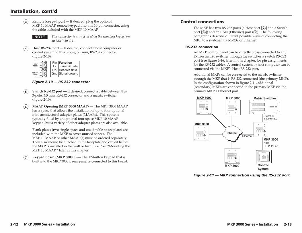
Control connectionsThe MKP has two RS-232 ports (a Host port [ 4 ] and a Switchport [ 5 ]) and an LAN (Ethernet) port ( 1 ). The followingparagraphs describe different possible ways of connecting theMKP to a switcher via RS-232 or Ethernet.
RS-232 connection
An MKP control panel can be directly cross-connected to anyExtron matrix switcher through the switcher’s switch RS-232port (see figure 2-16, later in this chapter, for pin assignmentsfor the RS-232 cable). A control system or host computer can beconnected via the MKP’s Host RS-232 port.
Additional MKPs can be connected to the matrix switcherthrough the MKP that is RS-232 connected (the primary MKP).In the configuration shown in figure 2-11, additional(secondary) MKPs are connected to the primary MKP via theprimary MKP’s Ethernet port.
Ethernet
MKP 3000
MKP 3000
MKP 3000
MKP 3000
MKP 3000 Host RS-232 Port
SwitcherRS-232 Port
Ethernet
Control System
Matrix Switcher I N P U T S
CONTROL
O U T P U T S
I/O
1 2 3 4 5 6 7 8 9 10 11 12
13 14 15 16 17 18 19 20 21 22 23 24
1 2 3 4 5 6 7 8 9 10 11 12
13 14 15 16 17 18 19 20 21 22 23 24
MAV 2400 SERIES SWITCHER
MKP 3000
VOLUME
I/O
I /O
SELECT
Extron MKP 3000
I/O
SELECT
Extron MKP 3000
I/O
SELECT
Extron MKP 3000
I/O
SELECT
Extron MKP 3000
Figure 2-11 — MKP connection using the RS-232 port
3 Remote Keypad port — If desired, plug the optionalMKP 10 MAAP remote keypad into this 10-pin connector, usingthe cable included with the MKP 10 MAAP.
This connector is always used on the standard keypad onan MKP 3000 L.
4 Host RS-232 port — If desired, connect a host computer orcontrol system to this 3-pole, 3.5 mm, RS-232 connector(figure 2-10).
Pin FunctionTXRXGnd
Transmit dataReceive dataSignal ground
TxHOST
RS-232
SWITCHRS-232
Rx
GND
Tx
Rx
GND
Figure 2-10 — RS-232 connector
5 Switch RS-232 port — If desired, connect a cable between this3-pole, 3.5 mm, RS-232 connector and a matrix switcher(figure 2-10).
6 MAAP Opening (MKP 3000 MAAP) — The MKP 3000 MAAPhas a space that allows the installation of up to four optionalmini architectural adapter plates (MAAPs). This space istypically filled by an optional four space MKP 10 MAAPkeypad, but a variety of other adapter plates are also available.
Blank plates (two single-space and one double-space plate) areincluded with the MKP to cover unused spaces. TheMKP 10 MAAP or other MAAP(s) must be ordered separately.They also should be attached to the faceplate and cabled beforethe MKP is installed in the wall or furniture. See “Mounting theMKP 10 MAAP,” later in this chapter.
7 Keypad board (MKP 3000 L) — The 12-button keypad that isbuilt into the MKP 3000 L rear panel is connected to this board.
2-12

MKP 3000 Series • InstallationMKP 3000 Series • Installation
Installation, cont’d
Wire the connectors as follows:
The total cable length between an MKP control paneland a matrix switcher should not exceed 100 feet (30 m).
1. Choose a cable such as Extron’s Comm-Link cable. Thewire specifications for Comm-Link cable are inappendix A, “Reference Information.” Colors may varyfrom this example.
2. Trim approximately 1.5" (3.8 cm) of the cable jacket toexpose the four insulated wires and a bare drain wire(silver-colored).
3. Cut off the foil shield and discard it.
4. Strip ¼" ( 0.6 cm) of insulation from three of the four wires.
5. Twist the strands of each wire, insert them into the directinsertion connector, and tighten the captive screws.
Ethernet connection
An MKP control panel can be directly connected to anyEthernet-enabled matrix switcher via the switcher’s Ethernetport (figure 2-13) using a TP (network) cable that is wired as acrossover cable (see “TP cable termination,” later in this chapter,to properly wire the cable).
MKP 3000
CrossoverCable
LAN Port
Matrix Switcher
INPUTS
CONTROL
OUTPUTS
I/O
1 2 3 4 5 6 7 8 9 10 11 12
13 14 15 16 17 18 19 20 21 22 23 24
1 2 3 4 5 6 7 8 9 10 11 12
13 14 15 16 17 18 19 20 21 22 23 24
MAV 2400 SERIES SWITCHER
I /O
SELECT
Extron MKP 3000
Figure 2-14 — Direct MKP connection using theLAN port
Any number of control panels can be connected as part of anetwork to any Ethernet-enabled matrix switcher via theswitcher’s Ethernet port (figure 2-14). All TP cables in thisexample are wired as patch (straight-through) cables.
2-152-14
Multiple primary MKPs can also be daisy-chained together,with the first MKP connected to the switcher’s RS-232 port andthe others connected to each other via their own RS-232 ports.Figure 2-12 shows an example of this type of configuration.
MKP 3000Primary/Pass-through
MKP 3000 LPrimary/MKP 3000
HostRS-232 Port
SwitcherRS-232 Port
Tx
Tx
Tx
Tx
Rx
Rx
Rx
Rx
SwitcherRS-232 Port
Matrix Switcher
INPUTS
CONTROL
I/O
MAV 3200 SERIES SWITCHER
INPUTS
OUTPUTS
1615
1413
1211
109
87
65
43
21
1615
1413
1211
109
87
65
43
21
3231
3029
2827
2625
2423
2221
2019
1817
3231
3029
2827
2625
2423
2221
2019
1817
PRIMARY
REDUNDANTPOWER SUPPLY
POWERRESET
I /O
SELECT
BACK
CANCEL
1
2
3
4
5
6
7
8
9
0
MKP 10
Extron
MKP 3000 MAAP
Extron
POWERRESET
I /O
SELECT
BACK
CANCEL
1
2
3
4
5
6
7
8
9
0VIDEOGREEN
AUDIORED
TAKE
OUTPUT
INPUT
MKP 3000 L
Figure 2-12 — Daisy-chaining MKP 3000s
RS-232 cable termination
Each MKP control panel has two RS-232 ports that areconnected using 3.5 mm, 3-pole direct insertion connectors.Figure 2-13 shows the pin assignments for these ports.
Pin Switcher RS-232 MKP RS-232
1 – – 2 Tx Rx 3 Rx Tx 4 – – 5 Gnd Gnd 6 – – 7 – – 8 – – 9 – –
Figure 2-13 — RS-232 cross-connection table

MKP 3000 Series • InstallationMKP 3000 Series • Installation
Installation, cont’d
• Crossover cable — Direct connection between the MKPand a host computer or an Ethernet-enabled matrixswitcher (figure 2-14)
• Patch (straight) cable — Network connection betweenthe MKP and an Ethernet LAN (figure 2-14)
For pin assignments, see figure 2-16, below.
Patch (straight) cable
Side 1 Side 2 Pin Wire color Pin Wire color
1 White-orange 1 White-orange
2 Orange 2 Orange
3 White-green 3 White-green
4 Blue 4 Blue
5 White-blue 5 White-blue
6 Green 6 Green
7 White-brown 7 White-brown
8 Brown 8 Brown
Crossover cable
Side 1 Side 2 Pin Wire color Pin Wire color
1 White-orange 1 White-green
2 Orange 2 Green
3 White-green 3 White-orange
4 Blue 4 Blue
5 White-blue 5 White-blue
6 Green 6 Orange
7 White-brown 7 White-brown
8 Brown 8 Brown
Clip DownSide
1
1&23&6 4&5
7&8
2345678
Pins12345678
RJ-45connector
TwistedPairs
Figure 2-16 — RJ-45 connector and pinout tables
2-172-16
Ethernet
MKP 3000
MKP 3000
MKP 3000
MKP 3000
RS-232
ControlSystem
Matrix SwitcherINPUTS
CONTROL
OUTPUTS
I/O
1 2 3 4 5 6 7 8 9 10 11 12
13 14 15 16 17 18 19 20 21 22 23 24
1 2 3 4 5 6 7 8 9 10 11 12
13 14 15 16 17 18 19 20 21 22 23 24
MAV 2400 SERIES SWITCHER
I /O
SELECT
Extron MKP 3000
I/O
SELECT
Extron MKP 3000
I/O
SELECT
Extron MKP 3000
I/O
SELECT
Extron MKP 3000
Figure 2-15 — Network MKP connection using theLAN port
Ethernet (TP) cable termination
It is vital that you use the correct Ethernet cables, and that theybe properly terminated with the correct pinout. Ethernet linksuse Category (CAT) 5, 5e or CAT 6, unshielded twisted pair(UTP) or shielded twisted pair (STP) cables, terminated withRJ-45 connectors. Ethernet cables are limited to 328' (100 m).
CAUTION Do not use standard telephone cables. Telephonecables do not support Ethernet or Fast Ethernet.
Do not stretch or bend cables. This can causetransmission errors.
The cable you use depends on your network speed. The MKPsupports both 10 Mbps (10Base-T — Ethernet) and 100 Mbps(100Base-T — Fast Ethernet), half-duplex and full-duplex,Ethernet connections.
• 10Base-T Ethernet requires CAT 5 UTP or STP cable as aminimum
• 100Base-T Fast Ethernet requires CAT 5e UTP or STPcable as a minimum
The Ethernet cable can be terminated as a straight-through cableor a crossover cable. It must be terminated properly for yourapplication (figure 2-16).

MKP 3000 Series • InstallationMKP 3000 Series • Installation
Installation, cont’d
2-18
Power supply wiringFigure 2-17 shows how to wire the power connector.
Power Supply Output Cord
Direct InsertionConnector
SECTION A–A
Ridges Smooth
A A
12 V
G
ND
Figure 2-17 — Power connector wiring
CAUTION Power supply voltage polarity is critical. Incorrectvoltage polarity can damage the power supply andthe MKP. Identify the power cord negative lead bythe ridges on the side of the cord (see figure 2-17,above).
To verify the polarity before connection, plug in the powersupply with no load and check the output with a voltmeter.
The length of the exposed (stripped) copper wires isimportant. The ideal length is 3/16" (5 mm). Longerbare wires can short together. Shorter wires are not assecure in the direct insertion connectors and could bepulled out.
Do not tin the power supply leads before installing themin the direct insertion connector. Tinned wires are not assecure in the connectors and could be pulled out.
The two power cord wires must be kept separatewhile the power supply is plugged in. Removepower before wiring.
Alternatively, you can use the optional Extron P/S 123Universal 12 VDC Power Supply, part #60-814-01, which canpower up to 10 Extron 12 VDC devices using only one ACpower connector.
Mounting the MKP 10 MAAPThe MKP 3000 MAAP has a space that allows the installation ofup to four optional mini architectural adapter plates. This spaceis typically filled by an optional four space MKP 10 MAAPkeypad (figure 2-18).
BACK CANCEL
1 2 3
4 5 6
7 8 9
0
MKP 10
Figure 2-18 — MKP 10 MAAP keypad
When the connected switcher has a large matrix size (up to 128by 128) selecting an input or output number by rotating theSelect knob can be inconvenient. The optional MKP 10 MAAPkeypad allows rapid input/output selection.
Mount the MKP 10 MAAP to the MKP 3000 MAAP beforeinstalling the MKP 3000 MAAP, as follows:
The proper MKP 10 MAAP orientation is with thepower LED up.
2-19

MKP 3000 Series • InstallationMKP 3000 Series • Installation
Installation, cont’d
1. Sandwich the MKP 3000 MAAP panel between theMKP 10 MAAP module (without its front panel) and theMKP 10 MAAP’s front panel. Secure the front panel to themodule with the included #4-40 screws (see figure 2-19 ).
POWERRESET
I /O
SELECT
Extron
MKP 3000 MAAP
BACK
CANCEL
1
2
3
4
5
6
7
8
9
0
MKP 10
(4) #4-40Screws
ExtronMKP 10Module
ExtronMKP 3000 MAAPPanel
ExtronMKP 10Front Panel
Figure 2-19 — Mounting the MKP 10 MAAP
2-20
2. See figure 2-20. If you have not already done so, connectthe serial control and power cables between the J1connector ( 1 ) on the MKP 10 MAAP and the RemoteKeypad port ( 2 ) on the rear of the MKP 3000 MAAP.
2
1
Figure 2-20 — MKP 3000 MAAP rear panel withMKP 10 MAAP mounted
1 MKP 10 MAAP J1 control connector
2 MKP 3000 MAAP Remote Keypad port
3. Mount the MKP 3000 MAAP (with the mountedMKP 10 MAAP) to the wall box or mounting bracket. See“Mounting the MKP to mud ring or wall box,” earlier inthis chapter.
2-21

MKP 3000 Series • Installation
Installation, cont’d
MKP 3000 Series
3Chapter Three
Local Operation
Front Panel Controls and Indications
Front Panel Operations
Rear Panel Resets
MKP 10 MAAP and MKP 3000 L Keypad Operation
2-22

MKP 3000 Series • Local OperationMKP 3000 Series • Local Operation
Local Operation
The labels in these buttons can be removed and replaced toreflect the function of the button. A sheet of labels is providedwith the MKP. See “Changing Button Labels” in appendix A,“Reference Information,” for the procedure for changing theselabels.
1 LCD display — Shows the input, output, preset name andnumber, or volume level during operation. In certain modes, itcan also show the IP addresses programmed into the MKP.
The LCD display shows the most recent input, output, orpreset name and number entered from this MKP. Tiescreated using other devices (other MKPs, a PC or controlsystem, or the matrix switcher’s front panel) are notshown in the LCD display.
2 Input/Preset button — Selects an input or places the MKP inpreset mode.
3 Output/View button — Selects an output or places the MKP inview mode.
4 Take button — Takes (activates) a new tie or preset. This buttonis the equivalent of the Enter button on the matrix switcher’sfront panel.
5 Select knob — This knob, when rotated, scrolls through theavailable inputs, outputs, or presets. It also ramps volume upor down, depending on which of buttons 2 and 3 and whichoperating mode are selected. The inputs, outputs, presets, orvolume level are shown in the LCD display ( 1 ).
When the connected switcher has a large matrix size (upto 128 by 128) selecting an input or output number byrotating the Select knob can be inconvenient. Anoptional MKP 10 MAAP keypad allows rapid input/output selection.
6 Keypad (MKP 3000 L) — Use these buttons to select inputsand/or outputs as an alternative to using the Select knob ( 5 ),on the MLK 3000 L only.
7 Power LED (MKP 3000 L) — When lit, this LED indicates thatpower is applied to the MKP 3000 L keypad.
8 Input/Output (I/O) (video/audio) selection button — Press theI/O button to select video and audio, video only, or audio onlyfor the current input and output selections. As you cyclethrough the selections, the button lights amber for video andaudio, green for video only, and red for audio only. This buttonalso selects audio volume mode.
3-33-2
Front Panel Controls and Indications
I /O
SELECT
Extron MKP 3000
INPUT TAKE OUTPUT
VIDEO GREEN
AUDIO RED
2 4 3
1
5
8
Figure 3-1 — MKP 3000 controls and indicators
The MKP 3000 MAAP front panel has the same controlsand indicators.
MKP 3000 L
BACK CANCEL
1 2 3
4 5 6
7 8 9
0
I /O
SELECT
INPUT TAKEOUTPUT
VIDEOGREEN
AUDIORED
Extron
43
1
52
78
6
Figure 3-2 — MKP 3000 L controls and indicators
The buttons on this panel perform different functions,depending on the MKP’s operating mode. See “Front PanelOperations,” later in this chapter, for a more detaileddescription of the modes.

MKP 3000 Series • Local OperationMKP 3000 Series • Local Operation
Local Operation, cont’d
3. Turn the Select knob clockwise or counterclockwise untilthe desired mode (Matrix or Input-Only) is displayed.
You can also change the tie mode by using SIScommands (see chapter 4, “SIS™ Operation,”) or theEthernet Web pages (see chapter 5, “HTMLOperation”).
Figure 3-7, “Selecting setup parameters,” later in this chapter,provides a diagram of the procedures for setting up the IPconnection, backlight duration, and tie mode parameters usingthe front panel controls.
Creating tiesAfter selecting the tie mode, use one of the followingprocedures to create the ties.
Creating a tie in matrix mode (default)
To create a tie in matrix mode (the default mode),
1. Select the type of tie (video, audio, or both) by repeatedlypressing the I/O button until it lights the desired color:
• Video and audio selected — The I/O button lightsamber.
• Video only selected — The I/O button lights green.
• Audio only selected — The I/O button lights red.
2. Press the Input button to specify that the next numberentered will be an input number.
• The Input button lights amber.
• If it was lit, the Output button turns off.
• The most recently selected output is locked (unableto be changed; assigned as the output to which theentered input is tied unless a different output isassigned [see steps 4 and 5]).
3. Use the Select knob to scroll through the available inputsuntil the LCD display shows the desired input.
The Select knob scrolls through only those inputs thatare within the available range for this MKP or theconnected matrix switcher. See “Switcher ControlSettings section” in chapter 5, “HTML Operation,” forinformation on authorizing inputs and outputs.
If an optional MKP 10 MAAP keypad is connected oryou are using an MKP 3000 L, you can use the keypadin place of the Select knob. See “MKP 10 MAAP andMKP 3000 L Keypad Operation,” later in this chapter.
3-5
Front Panel OperationsThe MKP 3000 normally operates in the matrix input/outputselection mode. This is the default mode, in which you can setup a tentative tie by selecting an input, selecting an output, andthen taking (commanding) the tie. The MKP 3000 can alsooperate in input-only mode, in which you can view the currentties by scrolling the outputs. In this mode, you first select anoutput, then complete the tie by selecting an input.
Additionally, the MKP can operate in preset mode (selectpresets), view mode (view ties without changing them), audiovolume mode (adjust the audio output volume), or setup mode(set the IP addresses and other parameters).
The MKP is provided with default labels installed in the frontpanel buttons (figure 3-3). It also includes a strip of alternativelabels that you can insert in one or more of the mode selectionbuttons to make using the other modes more clear. Theseadditional button labels are shown in the applicable front paneloperation descriptions. See “Changing Button Labels” inappendix A, “Reference Information,” for the procedure forreplacing these button labels.
SELECT
INPUT TAKEOUTPUT
VIDEOGREEN
AUDIORED
Figure 3-3 — Input/output selection mode labels
Changing the tie modeYou can create ties on the MKP 3000 in the following modes:
• Matrix mode (the default) — In matrix mode, you specifyan input and one or more outputs to be tied to it.
• Input-only mode — In input-only mode, you select oneoutput, then specify an input to be tied to it.
To change from one tie mode to the other,
1. Enter setup mode by simultaneously pressing and holdingbuttons 2 , 3 , and 4 (typically labeled Input, Output,and Take) for approximately 2 seconds until all buttonslight amber and the LCD display changes.
2. Repeatedly press the Input button (button 2 ) until theLCD window displays “Tie Mode.”
3-4

MKP 3000 Series • Local OperationMKP 3000 Series • Local Operation
Local Operation, cont’d
3-7
Creating a tie in input-only mode
In input-only mode, you select an output to which you can tieonly one input. To create a tie in input-only mode,
1. Select the type of tie (audio only, video only, or audio andvideo) by repeatedly pressing the I/O button until it lightsthe desired color:
• Video only selected — The I/O button lights green.
• Audio only selected — The I/O button lights red.
• Video and audio selected — The I/O button lightsamber.
2. Press the Output button to specify that the next numberthat is entered will be an output number.
• The Output button lights amber.
• If it was lit, the Input button turns off.
3. Turn the Select knob to scroll through the availableoutputs until the LCD window displays the desired outputnumber.
As you scroll through the outputs, the LCD displayindicates whether or not the output is tied.
The Select knob scrolls through only those outputs thatare within the available range for this MKP or theconnected matrix switcher. See “Switcher ControlSettings section” in chapter 5, “HTML Operation,” forinformation on authorizing inputs and outputs.
The LCD display shows the output that you selected andits status (tied or untied).
4. Press the Input button to specify that the next numberentered will be an input number.
• The Input button lights amber.
• If it was lit, the Output button turns off.
• The most recently selected output is locked (unableto be changed; assigned as the output to which theentered input is tied unless a different output isassigned [steps 2 and 3]).
5. Turn the Select knob to scroll through the available inputsuntil the LCD window shows your desired input number.
• The LCD display shows the input that you selectedand its status (tied or untied).
• The Take button blinks.
• The LCD display shows the input that you select.
• The Take button blinks.
The blinking Take button times out after 15seconds if it is not pressed.
4. Press the Output button to specify that the next numberentered is an output number.
• The Output button lights amber.
• If it was lit, the Input button goes out.
• The last selected input is locked (unable to bechanged; assigned as the input to which the enteredoutput is tied unless a different input is assigned [seesteps 2 and 3]).
5. Use the Select knob to scroll through the available outputsuntil the LCD display shows the desired output, or enterthe desired output number on the keypad (MKP 3000 L orMKP 3000 AAP with keypad only).
• The LCD display shows the output that you select.
• The Take button blinks.
The Select knob scrolls through only those outputs thatare inside the available range for this MKP or theconnected matrix switcher. See “Switcher ControlSettings section” in chapter 5, “HTML Operation,” forinformation on authorizing inputs and outputs.
When an input or output outside the available range forthis MKP or the connected matrix switcher is selectedusing an optional MKP 10 MAAP keypad or the keypadof the MLC 3000 L, the LCD display shows InvalidInput or Invalid Output.
6. Press the Take button to confirm the tie.
The blinking Take button times out after 15 seconds ifnot selected.
7. Repeat steps 5 and 6 for each additional output that youwant to add to the tie.
3-6

MKP 3000 Series • Local OperationMKP 3000 Series • Local Operation
Local Operation, cont’d
Viewing ties
SELECT
TAKEOUTPUT
HOLD
VIEW
VIDEOGREEN
AUDIORED
INPUT
Figure 3-4 — Suggested button labels for viewmode
To view existing ties,
1. Press and hold the Output button until the button lightsgreen to indicate view mode (approximately2 seconds), then release the button.
• The I/O button lights green to indicate that the LCDwill show video ties.
• The tied inputs and outputs are locked (unable to bechanged).
• The LCD display shows the output that is currentlyselected ( > ).
• The LCD shows the last tie created from the MKP.
Ties created using other devices (other MKPs, acomputer or control system, or the matrix switcher’sfront panel) are not shown in the LCD display until thepanel is accessed or the Output button is pressed torefresh the view.
2. Use the Select knob to scroll through the available outputs.The LCD display shows the following:
• The outputs as you scroll past them
• The input that is tied to each output as it is displayed
If an optional MKP 10 MAAP keypad is connected, youcan use it in place of the Select knob to select a specificoutput whose tied input you want to check. See“MKP 10 MAAP Operation,” later in this chapter.
3. If desired, press and release the I/O button to set the MKPto display audio ties.
• The I/O button lights red.
• If desired, view the audio ties as described in step 2.
4. To exit view mode, press and hold the Output button untilthe button lights amber to indicate I/O Selection mode(approximately 2 seconds) .
3-93-8
The Select knob scrolls only through those inputs thatare within the available range for this MKP or theconnected matrix switcher. See “Switcher ControlSettings section” in chapter 5, “HTML Operation,” forinformation on authorizing inputs and outputs.
6. Press the Take button to confirm the tie.
The blinking Take button times out after 15 seconds if itis not pressed.
If an optional MKP 10 MAAP keypad is connected oryou are using an MKP 3000 L, you can use the keypadin place of the Select knob. See “MKP 10 MAAP andMKP 3000 L Keypad Operation,” later in this chapter.
Deselecting a tie
To deselect (break) a tie,
1. Press the Input button.
2. Set the input to 0 by doing either of the following:
• Turn the Select knob until No Signal is displayed inthe LCD window.
• If an MKP 10 MAAP is installed in your MKP or youare using an MKP 3000 L, press 0 on its keypad.
The Take button begins to blink.
3. Press the Output button.
4. Select the output that you want to untie by doing either ofthe following:
• Turn the Select knob until the desired output numberis displayed in the LCD window.
• On the MKP 10 MAAP or the MKP 3000 L keypad,press the desired output number.
5. Press Take.

MKP 3000 Series • Local OperationMKP 3000 Series • Local Operation
Local Operation, cont’d
1. Press and hold the I/O button until it lights red to indicateaudio volume mode (approximately 2 seconds), thenrelease the button.
• The output button lights.
• The LCD display shows the selected ( > ) output anda slide bar that shows the audio output level of theselected output.
2. Press and release the Output button to toggle betweenselection ( > ) of the output and the audio level slide bar.
3. Use the Select knob to select an output, or to increase ordecrease the audio level.
• If Output is selected ( > ), the Select knob scrollsthrough the outputs.
If an optional MKP 10 MAAP keypad is connected oryou are using an MKP 3000 L, you can use the keypadin place of the Select knob. See “MKP 10 MAAP andMKP 3000 L Keypad Operation,” later in this chapter.
• If the audio level slide bar is selected, the Select knobchanges the audio level.
4. To exit audio volume mode, press and hold the I/O buttonfor approximately 2 seconds until the button lights amberto indicate I/O selection mode.
Viewing and configuring the IP and MKP setupparameters
To configure the MKP to operate in your LAN, you may need tochange one or more IP addresses and the host control portsetting. The duration of the LCD display’s back light is alsoadjustable. Figure 3-7, “Selecting setup parameters,” later inthis chapter, provides a diagram of the procedures for setting upthe IP connection, backlight duration, and tie mode parametersusing the front panel controls.
The following MKP parameters can be set from the front panelin setup mode:
• IP address (default = 192.168.254.253)
• Subnet address (default = 255.255.0.0)
• Gateway address (default = 0.0.0.0)
• The host matrix switcher’s IP address (default = 0.0.0.0)
• Host control port setting (pass-through or no pass-through) (default = no pass-through)
3-113-10
Selecting a preset
SELECT
TAKEOUTPUTINPUT
HOLD
PRESET
VIDEOGREEN
AUDIORED
Figure 3-5 — Suggested button labels for presetmode
• Presets must have been created in the matrix switcherto be valid. Refer to the user’s manual for theconnected matrix switcher to create presets.
• Presets must be named in the MKP 3000 to berecallable. See chapter 4, “SIS™ Operation,” andchapter 5, “HTML Operation,” to name presets.
To select (recall) a preset on the MKP 3000,
1. Press and hold the Input button until the button lightsgreen to indicate preset mode (approximately 2 seconds) .
• The I/O button becomes unlit.
• The LCD display shows Preset Mode and the nameof the last selected preset (if any).
If no preset has been named in the MKP or if no presethas been selected, the LCD window shows [Not Set].
2. Use the Select knob to scroll through the available presetsuntil the LCD display shows the desired preset name. TheTake button starts to blink.
3. Press the Take button to recall the preset.
4. To exit preset mode, press and hold the Input button, untilit lights amber to indicate I/O selection mode(approximately 2 seconds).
Adjusting the audio output
SELECT
TAKEOUTPUT
SELECT
HOLD
VOLUME
INPUT
Figure 3-6 — Suggested button labels for audiovolume mode

MKP 3000 Series • Local OperationMKP 3000 Series • Local Operation
Local Operation, cont’d
• Pressing button 3 changes the editable octet (movesthe caret) of the selected IP address, as shown infigure 3-6.
2. Use button 2 and button 3 to select and display thedesired address and octet.
3. Rotate the Select knob to increase or decrease the octetvalue until the LCD display shows the desired value.
If an optional MKP 10 MAAP keypad is connected oryou are using an MKP 3000 L, you can use the keypadin place of the Select knob.
4. Repeat steps 2 and 3 to select and change other addressesand/or octets.
5. Use button 2 to select the host control setting display.(See “Host control port setting and pass-throughcommunications,” below.)
6. If necessary, use button 3 or the Select knob to toggle thesetting between enabled (pass-through) and disabled (nopass-through). (See “Host control port setting and pass-through communications,” below.)
7. Use button 2 to select the connection priority display. Ifnecessary, use button 3 or the Select knob to toggle thesetting between primary and secondary.
8. If desired, set the LCD window’s backlighting interval.(See “Setting the LCD window backlighting,” on the nextpage.)
9. Select the tie mode. (See “Changing the tie mode,” earlierin this chapter.
10. When all addresses and other settings have been made,press the Take button 4 . The MKP 3000 reenters I/Oselection mode.
Host control port setting and pass-through communications
When the MKP is
• Connected to a computer or control system via its HostRS-232 port and
• In pass-through mode,
the MKP redirects valid matrix switcher SIS commands that itreceives on its Host RS-232 port to its Switcher RS-232 port.
3-13
• MKP connection setting
Primary — Controls the switcher directly (default).
Secondary — Controls the switcher through anotherMKP and its Switcher RS-232 port.
• LCD display backlighting interval
• Tie mode:
Matrix mode (default)
Input-only mode
Valid IP addresses consist of four 1-, 2-, or 3-digit numericsubfields (octets) separated by dots (periods). Each octet can benumbered from 000 through 255. Leading zeroes, up to threedigits total per octet, are optional. Values of 256 and above areinvalid.
If any of the default addresses conflict with other equipment atyour installation, you can change them to any valid value.
The MKP must be in the administrator executive modefor you to be able to set these parameters. In userexecutive mode, you cannot change the configuration.
CAUTION Editing the Extron IP address and other parameterswhile the MKP is connected via the LAN port canimmediately disconnect the computer from theMKP. Extron recommends editing this field usingthe front panel or the RS-232 link, and restrictingEthernet access to these parameters by assigning anadministrator’s password that is available only toqualified and knowledgeable personnel.
Edit these addresses and set the host control setting as follows:
1. Simultaneously press and hold buttons 2 , 3 , and 4
(typically labeled Input, Output, and Take) until allbuttons light amber and the LCD display changes(figure 3-7) to enter setup mode (approximately2 seconds).
• The LCD display shows the MKP’s IP address. Themost significant octet (first one on the left) of theMKP’s IP address is highlighted by a caret (>),indicating that it is editable.
• Pressing button 2 changes the IP address shown inthe LCD display, cycling through the various IPaddresses, and then selects the host control setting,the connection priority, and the LCD backlitduration, as shown in figure 3-6.
3-12

MKP 3000 Series • Local OperationMKP 3000 Series • Local Operation
Local Operation, cont’d
SELECT
SELECT
IP 192.168 add 254.253
>
IP 192.168 add 254.253
> IP 192.168 add 254.253 >
IP 192.168 add 254.253
IP 192.168 add 254.253
> >
Sub 255.255 net 000.000
> Sub 255.255 net 000.000 >
Sub 255.255 net 000.000
Sub 255.255 net 000.000
> >
Gate 000.000 way 000.000
> Gate 000.000 way 000.000 >
Gate 000.000 way 000.000
Gate 000.000 way 000.000
> >
Host 000.000 IP 000.000
> Host 000.000 IP 000.000 >
Host 000.000 IP 000.000
Host 000.000 IP 000.000
> >
Passthrough Disabled >
Passthrough Enabled >
Connection Primary >
Connection Secondary >
SELECTBacklight
30 Seconds
SELECT
INPUT
INPUT
INPUT
INPUT
INPUT
INPUT
INPUT
INPUT
TAKE
TAKE OUTPUT
OUTPUT OUTPUT
OUTPUT OUTPUT
OUTPUT OUTPUT
OUTPUT OUTPUT
INPUT
>Tie Mode Matrix
>
>Tie Mode
Input Only
The LCD shows MKP 3000’s IP address. The caret (>) shows the editable octet.
Press and hold these buttons for 2 seconds until they light amber.
This knob changes the editable octet/field.
MKP 3000’s IP Address
MKP 3000’s Subnet Mask
MKP 3000’s Gateway Address
Matrix Switcher’s
IP Address
Connection Priority
Backlight Duration
Host Control Setting
2
Press button or rotate the Select knob to toggle between the Enabled and Disabled selections.
Press button 3 to cycle through the selected ( > ) and editable octets.
3
Press button or rotate the Select knob to toggle between the Primary and Secondary selections.
Rotate the Select knob to set the LCD backlight to always on (0) or to timeout after 001 to 255 seconds.
Press and release button to execute all of the settings and exit Set-up mode.
Pre
ss b
utto
n 3
to
cycl
e th
roug
h th
e di
spla
yed
and
edita
ble
addr
esse
s an
d to
rea
ch th
e M
KP
set
up s
ettin
gs.
2
4 3
4
Tie ModeSELECT
OUTPUT OUTPUT
Press button or rotate the Select knob to toggle between the Matrix and Input Only selections.
3
3
3
Figure 3-7 — Selecting setup parameters
3-15
When the MKP is
• Connected to a computer or control system via its HostRS-232 port and
• In no pass-through mode,
the MKP acts on all valid MKP commands received. It does notpass the command to its Switcher RS-232 port.
When the MKP is
• Selected as primary:
The MKP directly controls the matrix switcher via itsSwitch RS-232 port or LAN port
• Selected as secondary:
The MKP controls the matrix switcher throughconnection to the primary MKP’s IP address
Setting the LCD window backlightingYou can use the front panel buttons to specify the amount ofseconds that the MKP’s LCD display will remain backlit after afront panel operation has been performed.
To set the backlighting interval, follow these steps:
1. Enter setup mode by simultaneously pressing and holdingbuttons 2 , 3 , and 4 (typically labeled Input, Output,and Take) until all buttons light amber and the LCDdisplay changes (approximately 2 seconds).
2. Repeatedly press the Input button (button 2 ) until theLCD window displays “Backlight.”
3. Turn the Select knob clockwise or counterclockwise untilthe desired number of seconds (0 to 255) is displayed.If you select 0 seconds, the backlighting is always on.
You can also change the backlighting interval by usingSIS commands (see chapter 4, “SIS™ Operation”).
Setup procedures diagramFigure 3-7 on the next page provides a diagram of theprocedures for setting up the IP connection, backlight duration,and tie mode parameters using the front panel controls.
3-14

MKP 3000 Series • Local OperationMKP 3000 Series • Local Operation
Local Operation, cont’d
When you unlock the control panel, the MKP 3000enters setup mode. Make changes if desired and thenpress the Take button to exit.
For an MKP 3000 L or an MKP 3000 connected to anMKP 10 MAAP:
1. On the MKP 10 MAAP or the MKP 3000 L keypad, pressand hold the 1, 3, Back, and Cancel buttons until the MKP3000 LCD window displays the name of the executivemode that has been set approximately 3 seconds).(Admin Mode and User Mode are displayed briefly; PanelLocked remains displayed.)
2. If necessary, repeat step 1 until the LCD window indicatesthe mode you want.
Resets from the Rear PanelYou can perform two types of resets from the rear panel of theMKP 3000: soft and hard.
Performing soft resetsThe remote control panel has three soft resets available thatrestore various tiers of MKP settings to their default settings.
• Events (mode 3) reset — Restarts the communicationsand control events.
• IP system (mode 4) reset — IP system reset resets most IPprotocols to their default settings.
IP system reset clears the Internet protocol (IP) settings,but does not reset the target address, the host controlsetting, the priority setting, or any user-loaded files.
• Absolute (mode 5) reset — Performs all of the systemreset functions and clears the MKP’s IP address to192.168.254.253 and its subnet mask to 255.255.0.0. Thisfunction is identical to the SIS command Esc ZQQQ (seechapter 4, “SIS™ Operation”).
3-173-16
Control panel security lockout (executive mode)The front panel security lockout limits the MKP’s front paneloperation to input selection, output selection, preset selection,and volume control only, depending on the MKP’s mode (IPaddress modification is locked).
The MKP 3000 provides the following three levels of front panelsecurity lockout (executive modes):
Panel Locked mode — All front panel controls are locked.Selections and setup cannot be performed from the frontpanel.
User mode — Front panel operation is limited to input, output,and preset selection, and volume control. The panelconfiguration, IP, and switcher addressing functions arelocked.
Administrator mode (default) — All front panel controls areavailable.
For an MKP 3000 without an MKP 10 MAAP connected,
1. Press and hold all four front panel buttons (figure 3-8)until all four buttons blink and then light amber, and theLCD displays the name of the executive mode that wasentered (approximately 3 seconds).
• Administrator mode — The LCD window brieflydisplays “Admin Mode,” then returns to what waspreviously displayed.
• User mode — The LCD window briefly displays“User Mode,” then returns to what was previouslydisplayed.
• Panel Locked mode — The LCD window displays“Panel Locked” until the executive mode is changed.
2. If necessary, repeat step 1 until the desired executive modeis entered.
I /O
SELECT
INPUT TAKE OUTPUT
VIDEO GREEN
AUDIO RED
Simultaneously press and holdall buttons for 3 seconds.All buttons blink and then light amber. Release the buttons.
Figure 3-8 — Control panel lockout

MKP 3000 Series • Local OperationMKP 3000 Series • Local Operation
Local Operation, cont’d
3-18
Perform a soft reset of the MKP as follows:
1. Press and hold the Reset (R) button until the Reset LEDblinks once (events reset), twice (IP system reset), or threetimes (absolute reset) (figure 3-9).
R
R
R
R
R
R
R
R
R
6 seconds
LED flashes twice.
3 seconds
LED flashes once.
Press and hold the Reset button. Release, then
immediatelypress and release again.
Release, thenimmediatelypress and release again.
Release, thenimmediatelypress and release again.
Absolute (mode 5)
Reset
Press and hold the Reset button.
IP System (Mode 4)
Reset
Press and hold the Reset button.
Events (Mode 3)
Reset
9 seconds
LED flashes three times.
Figure 3-9 — Performing soft resets
2. Release the Reset button and then immediately press andrelease the Reset button again. Nothing happens if thesecond momentary press does not occur within 1 second.
Performing a hard resetThe hard reset restores the MKP to the original factory defaultfirmware configuration and erases all user-installed software orfirmware. (A hard reset does not perform all possible MKPreset functions.)
CAUTION Ensure that you have backed up any locally-createdHTML, JavaScript, or other files that you haveuploaded to the MKP’s user file space before youperform the hard reset. A hard reset will erase alllocally-created files from the MKP.
Perform a hard reset as follows:
1. If necessary, turn off power to the switcher.
2. Press and hold the Reset button on the rear panel whileyou apply AC power to the MKP (figure 3-10).
R
R
Press and hold the Reset button while you apply power to the MKP.
The LED flashes on and off.
Release the Reset button.
Power
12 VDCPower Supply
Figure 3-10 — Performing a hard reset
3-19

MKP 3000 Series • Local Operation
Local Operation, cont’d
MKP 3000 Series
4Chapter Four
SIS™ Operation
RS-232 Links
Ethernet Link
Host-to-MKP Instructions
MKP-Initiated (Unsolicited) Messages
MKP Error Responses
Using the Command/Response Table
3-20
MKP 10 MAAP and MKP 3000 L KeypadOperation
When the connected switcher has a large matrix size (up to 128inputs by 128 outputs), selecting an input or output number byrotating the Select knob can be inconvenient. The optionalMKP 10 MAAP keypad (figure 3-11) and the built-inMKP 3000 L keypad allow rapid input/output selection.
BACK CANCEL
1 2 3
4 5 6
7 8 9
0
MKP 10
24
1
3
BACK CANCEL
Figure 3-11 — Optional MKP 10 MAAP keypad
The keypad on the MKP 3000 L is laid out and functionsthe identically to the MKP 10 MAAP keypad.
1 Power LED — When lit, this LED indicates that power isapplied to the keypad.
2 Cancel key — Press and release the Cancel key to reset theselected input or output value shown in the MKP 3000’s LCDdisplay to 000 before using the numeric keys ( 3 ) to enter aspecific value.
3 Numeric keys — Press and release the numeric keys (0 through9) to enter a specific value as the selected input or output shownin the MKP 3000’s LCD display.
4 Back key — Press and release the Back key to backspace (erase)the least-significant (rightmost) digit shown in the LCD display.

MKP 3000 Series • SIS™ OperationMKP 3000 Series • SIS™ Operation
SIS™ Operation
• Connection directly to a host computer requires acrossover cable.
• Connection via an Ethernet LAN requires a patch(straight-through) cable.
See “TP cable termination” in chapter 2, “Installation,”to create crossover and patch cables.
Default IP addressTo access the MKP via the Ethernet port, you need the Extron IPaddress. If the address has been changed to an addresscomprised of words and characters (DHCP host name), you candetermine the actual numeric IP address using the ping (ICMP)utility. If the address has not been changed, the factory-specified default is 192.168.254.253.
Host-to-MKP InstructionsThe MKP accepts SIS (Simple Instruction Set) commandsthrough the Host RS-232 and Ethernet ports. SIS commandsconsist of one or more characters per command field. They donot require any special characters to begin or end the commandcharacter sequence. Each MKP response to an SIS commandends with a carriage return and a line feed (CR/LF = ), whichsignals the end of the response character string. A string is oneor more characters.
MKP-Initiated (Unsolicited) MessagesWhen a local event such as a front panel operation occurs, theMKP responds by sending a message to the host. The MKP-initiated messages are listed below (underlined).
(C) Copyright 2006, Extron Electronics, MKP 3000 LCD Keypad,Vx.xx, 60-710-00 (for RS-232 connection)
(C) Copyright 2006, Extron Electronics, MKP 3000 LCD Keypad,60-710-00
Www, DD Mmm YYYY hh:mm:ss (for IP connection)
The MKP initiates the copyright message when it is firstpowered on or when connection via Internet protocol (IP) isestablished. In the IP connection response,
Vx.xx = firmware version numberWww = day of the week (first three letters)DD = day of the month (two digits with leading zero if needed)Mmm = month (first three letters)YYYY = year
hh = hour; mm = minutes; ss = seconds
4-3
RS-232 LinksThe MKP’s rear panel 3-pole, 3.5 mm, Host RS-232 connector(figure 4-1) can be connected to the RS-232 serial port output ofa host device such as a computer running the HyperTerminalutility, an RS-232 capable PDA, or a control system. Thisconnection makes software control of the control panel possible.The rear panel Switcher connector can be connected to theRemote or RS-232 port of a matrix switcher.
The default protocol for both ports is as follows:
• 9600 baud* • no parity• 8-bit, 1 stop bit • no flow control
Pin FunctionTXRXGnd
Transmit dataReceive dataSignal ground
TxHOST
RS-232
SWITCHRS-232
Rx
GND
Tx
Rx
GND
Figure 4-1 — RS-232 connector pin assignments
*The default baud rate is 9600, but this can be changed,using the MKP’s Web pages, to 300, 600, 1200, 1800,2400, 3600, 4800, 14400, 19200, 28800, 38400, 57600,or 115200 baud to match the switcher’s baud rate. See“Port (RS-232) Settings” in chapter 5, “HTMLOperation,” to change the baud rate.
Routing matrix switcher commandsWhen the MKP is connected to the matrix switcher via itsSwitcher RS-232 port, the MKP can redirect SIS matrix switchercommands received on the Host RS-232 port to the matrixswitcher.
If the MKP receives a valid matrix switcher SIS command on itsHost RS-232 port, it redirects the command to its SwitcherRS-232 port only if the MKP is set to Pass-through mode. Seethe “RS-232 port redirect” command set on page 4-9 or “HostControl Port settings” in chapter 5, “HTML Operation,” to setthe Pass-through mode.
Ethernet LinkThe rear panel LAN connector on the MKP can be connecteddirectly to a host computer (for setup) or a matrix switcher (forswitcher control), or to an Ethernet LAN or WAN (to which ahost computer, other MKPs, and a matrix switcher can also beconnected).
4-2

MKP 3000 Series • SIS™ OperationMKP 3000 Series • SIS™ Operation
SIS™ Operation, cont’d
Using the Command/Response TableThe command/response table begins on page 4-9. Lowercaseletters are acceptable in the command field except whereindicated. The table below shows the hexadecimal equivalentof each ASCII character used in the command/response table.
ASCII to HEX Conversion Table
•
The MKP always redirects a subset of valid matrix switcher-specific SIS commands on its Ethernet port and, if configured inpass-through mode, on its Switcher RS-232 port.
It is not the purpose of this manual to define in detail thepassed-through matrix switcher-specific SIS commands.Refer to the applicable matrix switcher’s manual.
Symbols are used throughout the tables to represent variables inthe command/response fields. Command and responseexamples are shown throughout the MKP SIS commands table.
4-5
Password:
The MKP initiates the password message immediately after thecopyright message when the controlling system is connectedusing TCP/IP or Telnet, and the MKP is password protected.This message means that the MKP requires an administrator oruser level password before it performs the commands enteredvia this link. The MKP repeats the password message responsefor every entry other than a valid password until a validpassword is entered.
Login Administrator
Login User
The MKP initiates the login message when a correctadministrator or user password has been entered. If the userand administrator passwords are the same, the MKP defaults toadministrator privileges.
Str
The MKP initiates the Str message whenever a front panelbutton or knob is operated. This includes the optionalMKP 10 MAAP keypad, if connected, and the standardMKP 3000 L keypad.
MKP Error ResponsesWhen the MKP receives an SIS command and determines that itis valid, it performs the command and sends a response to thehost device. If the MKP is unable to perform the commandbecause the command is invalid or contains invalid parameters,the MKP returns an error response to the host. The errorresponse codes are:
E01 — Invalid input channel number (too large)E10 — Invalid commandE12 — Invalid output number (too large)E13 — Invalid value (out of range)E14 — Illegal command for this configurationE24 — Privilege violation (Ethernet, Extron software only)E99 — Invalid or no response from target switcher
4-4

MKP 3000 Series • SIS™ OperationMKP 3000 Series • SIS™ Operation
SIS™ Operation, cont’d
X11 = Baud rate 300, 600, 1200, 1800, 2400, 3600, 4800,9600 (default), 14400, 19200, 28800,38400, 57600, or 115200
X12 = Parity (1st character only) Odd, Even, None (default), Mark,Space
X13 = # of data bits 7, 8 (default)
X14 = # of stop bits 1 (default), 2
X15 = Input or output number 0 through 999
X16 = Name 11 characters maximum for inputsand outputs12 characters maximum for presets24 characters maximum for MKPname.Upper- and lowercase alphanumericcharacters, spaces, – and / are valid.
The following characters are invalid in the name:+ ~ , @ = ‘ [ ] { } < > ’ “ ; : | \ and ?.
X17 = Preset number
X18 = Default name Factory default name(combination of the model name+ last 3 pairs of MAC address).
X19 = Time and date (set) MM/DD/YY-HH:MM:SSwhere:MM = month: 01 (Jan.) — 12 (Dec.)DD = day: 01 through 31YY = year: 00 through 99HH = hour: 00 through 24MM = minutes: 00 through 59SS = seconds: 00 through 59
X20 = Time and date (read) Day,•DD•Mmm•YYYY•HH:MM:SSwhere:Day = weekday: Mon through SunDD = day: 01 through 31Mmm = month: Jan through DecYYYY = year: 2000 through 2099HH = hour: 00 through 24MM = minutes: 00 through 59SS = seconds: 00 through 59
X21 = GMT offset –12.0 through +14.0. Hours andminutes removed from GMT
4-7
Symbol definitions= CR/LF (carriage return/line feed)
= CR (carriage return — no line feed)
• = space
X1 = On/off status 0 = off/disable1 = on/enable
X2 = RS-232 port number 1 = host2 = switcher
X3 = n = –1= redirect serial port data from the specified port to allowfor a transparent pass through mode. The response is returnedwith leading zeroes.n = the maximum number of serial ports that the IP link supports.X5 is verified at this port.
X4 = Time (in 10 ms increments) to wait for receive data beforereleasing the port to another source (min = 1 [10 ms],maximum = 32767 [32.767 seconds], default = 10 [100 ms]).
X5 = Numerical value (nnnn) to set L (length of message to receive) orassign as a D (delimiter).L = number of byte count (min = 0, max = 32767, default = 0).D = decimal number for ASCII character (min = 0, maximum = 00255, default = 00000L).
The numeric value directly precedes the identifier; for example: X5 = “3L”to specify a 3-byte length or X5 = “10D” to specify an ASCII delimiter of0A. The identifier, “L” or “D” is case sensitive and must be uppercase.
X6 = Firmware version Bootstrap version (x.xx)
X7 = Verbose firmware version-description-upload date/time. Seepage 4-10.
X8 = Voltage 1 (3.3 V), Voltage 2 (12.0 V),Temperature (degrees Fahrenheit)(xxx.xx), Voltage 3 (5.0 V)
X9 = Verbose/response mode 0 = no password assigned1 = verbose mode2 = tagged responses for queries3 = 1 and 2 (verbose and tagged)
The default X9 value is 0 for Telnet and 0 for RS-232.
If tagged responses are enabled, all read commands return the constantstring plus the data, the same as setting the value. For example, the MKPresponds Ipn•X18 to the Esc •CN command.
X10 = Security level 0 = clear/none11 = user password assigned12 = administrator password assigned
4-6

MKP 3000 Series • SIS™ OperationMKP 3000 Series • SIS™ Operation
SIS™ Operation, cont’d
4-9
X22 = Daylight Savings Time 0 = Daylight Savings Time off/ignore1 = Daylight Savings Time on (northern hemisphere)2 = Daylight Savings Time on (Europe)3 = Daylight Savings Time on (Brazil)
X23 = IP address ###.###.###.###
X24 = Hardware (MAC) address ##-##-##-##-##-##
X25 = Connection priority 0 = Primary1 = Secondary
X26 = Password 12 digits, alphanumericThe following characters are invalid in passwords:{space} + ~ @ = ‘ [ ] { } < > ’ “ ; : | \ and ?.
X27 = Web page priority 0 = Internal (default on power up)1 = User
X28 = Executive mode 0 = Administrator mode (panelunlocked)
1 = User mode2 = Panel locked
X29 = Tie mode 0 = Matrix mode1 = Input-only mode
4-8
Co
mm
an
d/r
esp
on
se t
ab
le f
or
MK
P S
IS c
om
man
ds
Co
mm
an
dA
SC
II C
om
man
dR
esp
on
seA
dd
itio
nal
desc
rip
tio
n(h
ost
to
MK
P)
(MK
P t
o h
ost
)
Fro
nt
pan
el
secu
rity
lo
cko
ut
(execu
tive m
od
e)
Pan
el lo
cked
mod
e2x
Exe
2 L
ock
fron
t pan
el.
Use
r m
ode
1xE
xe1
Ena
ble
only
inpu
t, ou
tput
, pre
set,
and
vol
ume
sele
ctio
n fr
om th
e fr
ont p
anel
.A
dm
inis
trat
or m
ode
0xE
xe0
Unl
ock
fron
t pan
el.
Vie
w fr
ont p
anel
lock
sta
tus
xX
28
Show
fron
t pan
el lo
ck s
tatu
s. F
or X
28:
0 =
Ad
min
istr
ator
mod
e (p
anel
unl
ocke
d).
1 =
Use
r m
ode.
2 =
Pan
el lo
cked
.
Pass
-th
rou
gh
(R
S-2
32 p
ort
red
irect
)C
onfi
gure
red
irec
t mod
eE
sc X
2 *
X3
* X
4 *
X5
CD
Cpn
X2
• C
cd X
3 ,
X4
, X
5
Turn
red
irec
t mod
e on
.E
xam
ple:
Esc
1*2*
50*1
0D*C
DC
pn01
• C
cd00
002,
0005
0,00
000L
R
edir
ect p
ort 1
to p
ort 2
. W
ait 5
00 m
s fo
r re
spon
se.
The
“L”
or
“D”
delim
iter
in v
alue
X5
is c
ase
sens
itiv
e an
d m
ust b
e up
perc
ase.
Dis
able
red
irec
tE
sc X
2 *
0C
DC
pn X
2 •
Ccd
0000
0,00
000,
0000
0L
Vie
w r
edir
ect
Esc
X2
CD
X3
, X
4 ,
X5
V
iew
red
irec
t mod
e on
/of
f sta
tus.
Info
rmati
on
req
uest
sIn
form
atio
n re
ques
tI
MK
P •
3000
• L
CD
• K
EY
PAD
or
MK
P •
3000
• L
CD
Req
uest
for
part
num
ber
N60
-7xx
-00
MK
P 30
00 a
nd M
KP
3000
MA
AP
wit
hout
MK
P 10
:60
-708
-00
MK
P 30
00 L
: 60
-709
-00
MK
P 30
00 M
AA
P w
ith
MK
P 10
: 60-
710-
00

MKP 3000 Series • SIS™ OperationMKP 3000 Series • SIS™ Operation
SIS™ Operation, cont’d
4-11
Co
mm
an
d/r
esp
on
se t
ab
le f
or
MK
P S
IS c
om
man
ds
(co
nti
nu
ed
)
Co
mm
an
dA
SC
II C
om
man
dR
esp
on
seA
dd
itio
nal
desc
rip
tio
n(h
ost
to
MK
P)
(MK
P t
o h
ost
)
RS-2
32 p
ort
co
nfi
gu
rati
on
Con
figu
re s
eria
l por
tE
sc X
2 *
X11
, X
12 ,
X13
, X
14 C
P C
pn X
2 •
Ccp
X11
* X
12 *
X13
* X
14
Exa
mpl
e:E
sc1*
9600
,n,8
,1C
PC
pn01
•Ccp
9600
,N,8
,1 9600
bau
d, n
o pa
rity
, 8 d
ata
bits
, 1 s
top
bit.
Vie
w p
ort c
onfi
gura
tion
Esc
X2
Cp
X11
* X
12 *
X13
* X
14
Inp
ut
an
d o
utp
ut
nam
es
– vid
eo
Nam
e a
vid
eo in
put
Esc
X15
, X
16 N
I N
mi
X15
• X
16N
ame
vid
eo in
put
X15
“X
16“.
Exa
mpl
e:E
sc1,
PC
1N
IN
mi0
01•P
C 1
Nam
e in
put 1
“PC
1”.
Rea
d a
vid
eo in
put n
ame
Esc
X15
NI
X16
In
put
X15
is n
amed
“X
16“.
Nam
e a
vid
eo o
utpu
tE
sc X
15 ,
X16
NO
N
mo
X15
• X
16
Nam
e vi
deo
out
put
X15
“X
16“.
Exa
mpl
e:E
sc05
,Mon
itor
5N
ON
mo0
05•M
onit
or 5
Nam
e ou
tput
5 “
Mon
itor
5”.
Rea
d a
vid
eo o
utpu
t nam
eE
sc X
15 N
OX
16
Out
put
X15
is n
amed
“X
16“.
Inp
ut
an
d o
utp
ut
nam
es
– au
dio
The
follo
win
g au
dio
inpu
t/ou
tput
nam
ing
com
man
ds a
re c
ase-
sens
itiv
e.
Nam
e an
aud
io in
put
Esc
X15
, X
16 N
a N
ma
X15
• X
16N
ame
aud
io in
put
X15
“X
16“.
Exa
mpl
e:E
sc1,
PC
1N
a N
ma0
01•P
C 1
Nam
e in
put 1
“PC
1”.
Rea
d a
n au
dio
inpu
t nam
eE
sc X
15 N
aX
16
Inpu
t X
15 is
nam
ed “
X16
“.N
ame
an a
udio
out
put
Esc
X15
, X
16 N
A
Nm
A X
15 •
X16
N
ame
aud
io o
utpu
t X
15 “
X16
“.E
xam
ple:
Esc
05,M
onit
or 5
NA
Nm
A00
5•M
onit
or 5
Nam
e ou
tput
5 “
Mon
itor
5”.
Rea
d a
n au
dio
out
put n
ame
Esc
X15
NA
X16
O
utpu
t X
15 is
nam
ed “
X16
“.
4-10
Co
mm
an
d/r
esp
on
se t
ab
le f
or
MK
P S
IS c
om
man
ds
(co
nti
nu
ed
)
Co
mm
an
dA
SC
II C
om
man
dR
esp
on
seA
dd
itio
nal
desc
rip
tio
n(h
ost
to
MK
P)
(MK
P t
o h
ost
)
Info
rmati
on
req
uest
s, c
on
tin
ued
Que
ry fi
rmw
are
vers
ion
QX
6
Firm
war
e ve
rsio
n x.
xx.
Que
ry v
erbo
se fi
rmw
are
vers
ion
0QX
7
Prov
ide
a d
etai
led
sta
tus
of th
e E
ther
net p
roto
col
firm
war
e, th
e M
KP
cont
rolle
r fi
rmw
are,
and
any
firm
war
e up
grad
e. T
he fi
rmw
are
that
is r
unni
ng is
mar
ked
by
an a
ster
isk
(*).
A c
aret
(^) i
ndic
ates
that
the
firm
war
e ha
s a
bad
che
cksu
m o
r an
inva
lidlo
ad.
?.??
ind
icat
es th
at fi
rmw
are
is n
ot lo
aded
.R
espo
nse
desc
ript
ion:
Eth
erne
t pro
toco
l fir
mw
are
vers
ion
- con
trol
ler
firm
war
e ve
rsio
n - u
pdat
ed fi
rmw
are
vers
ion
Que
ry s
tatu
sS
X8
Vo
ltag
e an
d te
mpe
ratu
re r
ead
ings
.
Rese
tsN
ames
res
etE
sc Z
XX
X
Zp
x E
rase
s al
l pre
sets
, pre
set n
ames
, inp
ut n
ames
, and
outp
ut n
ames
.A
bsol
ute
rese
tE
sc Z
Q
Zpq
Pe
rfor
m a
Nam
es r
eset
plu
s re
stor
atio
n of
all
def
ault
IP s
etti
ngs.
Verb
ose
mo
de
Set v
erbo
se m
ode
onE
sc X
9 C
V
Vrb
1 T
he M
KP
repo
rts
all s
tatu
s ch
ange
s to
the
dev
ice
that
sen
t the
com
man
d.
Rea
d v
erbo
se m
ode
Esc
CV
Rea
d c
onne
ctio
n’s
secu
rity
leve
lE
sc C
K
X10
Pa
ssw
ord
leve
l pro
tect
ion
assi
gned
.
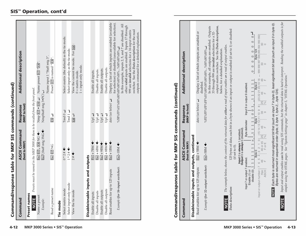
MKP 3000 Series • SIS™ OperationMKP 3000 Series • SIS™ Operation
SIS™ Operation, cont’d
4-134-12
Co
mm
an
d/r
esp
on
se t
ab
le f
or
MK
P S
IS c
om
man
ds
(co
nti
nu
ed
)
Co
mm
an
dA
SC
II C
om
man
dR
esp
on
seA
dd
itio
nal
desc
rip
tio
n(h
ost
to
MK
P)
(MK
P t
o h
ost
)
Pre
set
nam
es
Pre
sets
mus
t be
nam
ed in
the
MK
P 3
000
for
them
to b
e re
calle
d fr
om th
e fr
ont p
anel
.
Nam
e a
pres
etE
sc X
17 ,
X16
NG
N
mp
X17
• X
16
Nam
e pr
eset
X17
“X
16“.
Exa
mpl
e:E
sc7,
Staf
f mtg
3N
GN
mpS
taff
mtg
3•P
C1 N
ame
inpu
t 1 “
Staf
f mtg
3”.
Rea
d a
pre
set n
ame
Esc
X17
NG
X16
Pr
eset
X17
is n
amed
“X
16“.
Tie m
od
eSe
lect
mat
rix
mod
e0
* 2
# T
md
0
Sele
ct m
atri
x (t
he d
efau
lt) a
s th
e ti
e m
ode.
Sele
ct in
put-
only
mod
e1
* 2
# T
md
1
Sele
ct in
put-
only
as
the
tie
mod
e.V
iew
the
tie
mod
e2
# X
29
Vie
w th
e cu
rren
t tie
mod
e. F
or X
29 :
0 =
mat
rix
mod
e.1
= in
put-
only
mod
e.
Dis
ab
le/e
nab
le i
np
uts
an
d o
utp
uts
Ena
ble
all i
nput
sE
sc +
7B
M
Upl
E
nabl
e al
l inp
uts.
Dis
able
all
inpu
tsE
sc +
6B
M
Upl
D
isab
le a
ll in
puts
.E
nabl
e al
l out
puts
Esc
+ 9
BM
Upl
E
nabl
e al
l out
puts
.D
isab
le a
ll ou
tput
sE
sc +
8B
MU
pl
Dis
able
all
outp
uts.
Rea
d e
nabl
es fo
r up
to 1
25 in
puts
Esc
+ 1
BM
da
ta (s
ee b
elow
) D
ispl
ay a
list
of w
hich
inpu
ts a
re e
nabl
ed (a
vaila
ble
for
sele
ctio
n) o
r d
isab
led
(una
vaila
ble
for
sele
ctio
n).
Exa
mpl
e (f
or 1
6-in
put
swit
cher
):E
sc+
1BM
%
5B%
FF%
01%
00%
00%
00%
00%
00%
00%
...%
00%
00%
00%
In th
is e
xam
ple,
inpu
ts 2
, 5, a
nd 7
are
dis
able
d.
All
othe
r va
lid
inpu
ts a
re e
nabl
ed.
Inpu
ts 1
7 th
roug
h99
9 ar
e in
vali
d s
elec
tion
s fo
r a
16-i
nput
mat
rix
swit
cher
. Se
e th
e D
ata
desc
ript
ion
for
the
read
outp
uts
com
man
d fo
r a
det
aile
d e
xpla
nati
on.
Co
mm
an
d/r
esp
on
se t
ab
le f
or
MK
P S
IS c
om
man
ds
(co
nti
nu
ed
)
Co
mm
an
dA
SC
II C
om
man
dR
esp
on
seA
dd
itio
nal
desc
rip
tio
n(h
ost
to
MK
P)
(MK
P t
o h
ost
)
Dis
ab
le/e
nab
le i
np
uts
an
d o
utp
uts
, co
nti
nu
ed
Rea
d e
nabl
es fo
r up
to 1
25 o
utpu
tsE
sc +
5B
M
data
(see
bel
ow)
Dis
play
a li
st o
f whi
ch o
utpu
ts a
re e
nabl
ed o
rd
isab
led
.E
xam
ple
(for
32-
outp
ut s
wit
cher
):E
sc+
5BM
%
FE%
FF%
FF%
FF%
01%
00%
00%
00%
00%
...%
00%
00%
00%
In th
is e
xam
ple,
all
outp
uts
are
enab
led
. O
utpu
ts33
thro
ugh
999
are
inva
lid
sel
ecti
ons
for
a 32
-ou
tput
mat
rix
swit
cher
. Se
e th
e D
ata
desc
ript
ion,
belo
w, f
or a
det
aile
d e
xpla
nati
on.
The
exa
mpl
e be
low
, sho
ws
the
cont
ent o
f the
ret
urne
d da
ta fo
r ei
ther
a r
ead
of in
put e
nabl
es o
r a
read
of o
utpu
t ena
bles
.
Dat
a de
scri
ptio
n:12
5 by
tes
of d
ata;
eac
h bi
t in
a by
te s
how
s if
an
inpu
t or
outp
ut is
ena
bled
(if s
et to
1) o
r d
isab
led
(if s
et to
0).
7 In
put o
r ou
tput
num
ber:
Ena
ble
(1)
or
disa
ble
(0)
Inpu
t 7 o
r ou
tput
7 e
nabl
ed.
NO
TE
E
ach
byte
is re
turn
ed m
ost-s
igni
fican
t bit
first
(suc
h as
inpu
t 7 in
byt
e 0)
, lea
st-s
igni
fican
t bit
last
(suc
h as
inpu
t 0 in
byt
e 0)
.
Byt
es a
re re
turn
ed in
seq
uent
ial o
rder
(byt
e, 0
, byt
e 1,
byt
e 2,
...by
te 1
24).
6 5
4 3
2 1
0 15
14
13
1 1
1 1
1 1
1 n
1 1
1 1
1 0
0 1
1 1
1 1
1 1
12 1
1 10
9
8 23
22
21 2
0 19
18
Inp
ut 0
is a
lway
s 1
(ena
bled
). O
utp
ut 0
is a
lway
s 0
(dis
able
d).
Byt
e de
limet
er
Inpu
t 9 o
r ou
tput
9 d
isab
led.
Hex
: 46
Byt
e 0
Byt
e 1
Byt
e 2
46 o
r 45
25
25
A
SC
II:
F
F o
r E
%
%
0 0
0 0
0 0
0 0
998
997
996
995
Byt
e 12
4 99
9 99
4 99
3 99
2 30
30
0
0 46
46
F
F
46
39
F
9
...
Inpu
t and
out
put e
nabl
es c
an b
e re
ad u
sing
SIS
com
man
ds, b
ut th
e re
turn
ed d
ata
is h
ard
to in
terp
ret.
Rea
ding
the
enab
led
outp
uts
is fa
rsi
mpl
er u
sing
the
HT
ML
page
s. S
ee “
Syst
em S
etti
ngs
page
” in
cha
pter
5, “
HT
ML
Ope
rati
on.”

MKP 3000 Series • SIS™ OperationMKP 3000 Series • SIS™ Operation
SIS™ Operation, cont’d
4-154-14
Co
mm
an
d/r
esp
on
se t
ab
le f
or
MK
P S
IS c
om
man
ds
(co
nti
nu
ed
)
Co
mm
an
dA
SC
II C
om
man
dR
esp
on
seA
dd
itio
nal
desc
rip
tio
n(h
ost
to
MK
P)
(MK
P t
o h
ost
)
IP s
etu
pSe
t MK
P na
me
Esc
X16
CN
Ipn
X16
A
ssig
n a
nam
e to
the
MK
P.Se
t MK
P na
me
to fa
ctor
y d
efau
ltE
sc •
CN
Ip
n •
X18
R
eset
the
MK
P’s
nam
e to
the
fact
ory
def
ault
.R
ead
MK
P na
me
Esc
CN
X
16
Rea
d a
ssig
ned
MK
P na
me
(X16
may
be X18
).Se
t tim
e/d
ate
Esc
X19
CT
Ip
t X20
Se
t the
tim
e an
d d
ate.
Rea
d ti
me/
dat
eE
sc C
T
X20
R
ead
the
tim
e an
d d
ate.
Set G
MT
off
set
Esc
X21
CZ
Ip
z X
21
The
div
ider
bet
wee
n ho
urs
and
min
utes
is a
per
iod
.R
ead
GM
T o
ffse
tE
sc C
Z
X21
Se
t Day
light
Sav
ings
Tim
eE
sc X
22 C
X
Ipx
X22
Se
t the
sw
itch
er to
dis
play
the
loca
l tim
e as
Day
light
Sav
ings
Tim
e (+
1 ho
ur) i
n su
mm
erm
onth
s.R
ead
Day
light
Sav
ings
Tim
eE
sc C
X
X22
Set D
HC
P on
or
off
Esc
X1
DH
Id
h X
1
Cha
ngin
g D
HC
P to
off
rese
ts th
e M
KP
’s IP
add
ress
to it
s de
faul
t val
ue: 1
92.1
68.2
54.2
53.
Rea
d D
HC
P st
atus
Esc
DH
X
1
Set M
KP
IP a
dd
ress
Esc
X23
CI
IpiX
23
Rea
d M
KP
IP a
dd
ress
Esc
CI
X23
Rea
d h
ard
war
e (M
AC
) ad
dre
ssE
sc C
H
X24
Set s
ubne
t mas
kE
sc X
23 C
S Ip
s X
23
Rea
d s
ubne
t mas
kE
sc C
S X
23
Set g
atew
ay IP
ad
dre
ssE
sc X
23 C
G
Ipg
X23
IP s
etu
p,
con
tin
ued
Rea
d g
atew
ay IP
ad
dre
ssE
sc C
G
X23
Se
t tar
get (
swit
cher
) IP
para
met
ers
Esc
X23
— o
r —
X25
SI
Sip
X23
, X
24 ,
X25
T
he s
et ta
rget
IP p
aram
eter
s co
mm
and
can
be is
sued
wit
h ei
ther
the
targ
et IP
add
ress
(X
23) o
r th
e co
nnec
tion
pri
orit
y (X
25) v
aria
ble,
but n
ot b
oth.
The
res
pons
e is
as
show
n re
gard
less
of w
hich
var
iabl
e is
ent
ered
.
Rea
d ta
rget
(sw
itch
er) I
P pa
ram
eter
sE
sc S
I X
23 ,
X24
, X
25
Set t
arge
t (sw
itch
er) p
assw
ord
Esc
X26
PI
Spw
X26
Fo
r th
e se
t tar
get p
assw
ord
(Esc
X26
PI
) com
man
d, th
e pa
ssw
ord
(X26
) var
iabl
e ca
n be
eit
her
the
adm
inis
trat
or o
r th
e us
erpa
ssw
ord.
Cle
ar ta
rget
pas
swor
dE
sc •
PI
Spw
•
Rea
d ta
rget
pas
swor
dE
sc P
I **
**
The
ret
urne
d va
lue
for
the
read
targ
et p
assw
ord
com
man
d (E
sc P
I) i
s m
aske
d; th
e va
lue
is e
ithe
r em
pty
(no
retu
rn o
ther
than
the
) if n
o sw
itch
er p
assw
ord
is a
ssig
ned,
or
four
ast
eris
ks (*
***
) if a
pas
swor
d is
ass
igne
d.
Set M
KP
adm
inis
trat
or p
assw
ord
Esc
X26
CA
Ip
a X
26
Cle
ar M
KP
adm
inis
trat
or p
assw
ord
Esc
• C
AIp
a •
R
ead
MK
P ad
min
istr
ator
pas
swor
dE
sc C
A
X26
Se
t MK
P us
er p
assw
ord
Esc
X26
CU
Ip
u X
26
You
mus
t hav
e an
adm
inis
trat
or p
assw
ord
assi
gned
bef
ore
you
can
assi
gn a
use
r pa
ssw
ord.
Whe
n yo
u ha
ve c
onne
cted
mul
tipl
e M
KP
s to
con
trol
a s
wit
cher
thro
ugh
a pr
imar
y M
KP
con
trol
pan
el, d
o no
t set
a u
ser
pass
wor
d on
the
prim
ary
MK
P.
Cle
ar M
KP
user
pas
swor
dE
sc •
CU
Ipu
•
Rea
d M
KP
user
pas
swor
dE
sc C
U
X26
Co
mm
an
d/r
esp
on
se t
ab
le f
or
MK
P S
IS c
om
man
ds
(co
nti
nu
ed
)
Co
mm
an
dA
SC
II C
om
man
dR
esp
on
seA
dd
itio
nal
desc
rip
tio
n(h
ost
to
MK
P)
(MK
P t
o h
ost
)

MKP 3000 Series • SIS™ Operation
SIS™ Operation, cont’d
MKP 3000 Series
5Chapter Five
HTML Operation
Downloading the Startup Page
Viewing System Status
Using the Configuration Pages
Using the File Management Page
Saving and Restoring a Configuration
Special Characters
4-16
Co
mm
an
d/r
esp
on
se t
ab
le f
or
MK
P S
IS c
om
man
ds
(co
nti
nu
ed
)
Co
mm
an
dA
SC
II C
om
man
dR
esp
on
seA
dd
itio
nal
desc
rip
tio
n(h
ost
to
MK
P)
(MK
P t
o h
ost
)
IP s
etu
p,
con
tin
ued
Swit
ch W
eb p
age
prio
rity
Esc
X27
Cpa
g Iw
p X
27
Rea
d W
eb p
age
prio
rity
Esc
Cpa
g X
27
Set v
erbo
se m
ode
Esc
X1 C
V
Vrb
X1
Set M
KP
to r
epor
t cha
nges
from
oth
er s
ourc
es.
Rea
d v
erbo
se m
ode
Esc
CV
X
1
Rea
d th
e ve
rbos
e m
ode.
Rea
d c
onne
ctio
n’s
secu
rity
leve
lE
sc C
K
X10
Back
up
an
d r
est
ore
un
it c
on
fig
ura
tio
nSa
ve u
nit c
onfi
gura
tion
Esc
1*
{con
fig
type
} XF
Cfg
1*
{con
fig
type
} {c
onfi
g ty
pe} =
2 =
uni
t-sp
ecif
ic p
aram
eter
s(b
ox.c
onfi
g) s
uch
as g
loba
l pre
set n
ames
, aud
io/
vid
eo in
put a
nd o
utpu
t nam
es.
The
file
s ar
e st
ored
in th
e d
irec
tory
/no
rtxe
-bac
kup,
cre
ated
on
the
unit
by
the
Save
com
man
ds.
Res
tore
uni
t con
figu
rati
onE
sc 0
* {c
onfi
g ty
pe} X
F C
fg 1
* {c
onfi
g ty
pe}

MKP 3000 Series • HTML OperationMKP 3000 Series • HTML Operation
HTML Operation
5-3
Figure 5-1 — Enter Network Password page
A User name entry is not required.
5. In the Password field, enter the appropriate administratoror user password. Click OK.
The MKP checks several possibilities, in the followingorder, and then responds accordingly:
• If the address includes a specific file name, such as10.13.156.10/file_name.html, the MKP downloadsthat HTML page.
• If there is a file in the MKP’s memory that is named“index.html,” the MKP downloads “index.html” asthe default startup page.
• If neither of the above conditions is true, the MKPdownloads the System Status page (figure 5-2),which is the factory-installed default startup pagewith the file name “nortxe_index.html.”
You can now select the tabs at the top of the screen to displayadditional pages that enable you to configure and control theMKP 3000.
5-2
You can use a Web browser, such as Microsoft’s InternetExplorer, to configure the MKP through its Ethernet port, whenit is connected via a LAN or WAN. The browser’s display of theMKP’s configuration has the appearance of Web pages. Thischapter describes the factory-installed HTML pages, which arealways available and cannot be erased or overwritten.
If your Ethernet connection to the matrix switcher isunstable, try turning off the proxy server in your Webbrowser as follows:
1. In Microsoft’s Internet Explore, select Tools > Internet Options > Connections > LAN Settings.
2. Clear the Use a proxy server... check box.
3. Click Ok.
Downloading the Startup PageAccess the MKP using HTML pages as follows:
1. Start the Web browser program.
2. Enter the MKP’s IP address in the browser’s Address field.
If the local system administrators have not changed thevalue, the factory-specified default, 192.168.254.253, isthe correct value for this field.
3. If you want the browser to display a page other than theMKP 3000 Web page (such as a custom page that you havecreated and uploaded), enter a slash (/) after the address,and the name of the Web page file that you want todisplay.
The browser’s Address field should display the address inthe following format:xxx.xxx.xxx.xxx/{optional_file_name.html}.
Using any of the following characters results in aninvalid name:{space} + ~ , @ = ‘ [ ] { } < > ’ “ ; : | \ and ?.
4. Press Enter on your keyboard. The MKP checks to see if itis password protected.
If the MKP is not password protected, proceed to step 6.
If the MKP has a password, the network password promptwindow appears (figure 5-1).

MKP 3000 Series • HTML OperationMKP 3000 Series • HTML Operation
HTML Operation, cont’d
5-5
Using the Configuration PagesThe Configuration tab has six Web pages, which onlyadministrators can access. Links to them are listed in thesidebar menu at the left of the configuration screen. Thefollowing sections describe the changes you can make fromthese pages.
System Settings pageThe System Settings page (figure 5-3) is divided into threesections: IP Settings, Switcher Control Settings, and Date/TimeSettings. In each section, click Submit to enter your changes.Clicking the Cancel button in any section restores the previoussettings, if the new values have not been submitted.
Figure 5-3 — System Settings page
5-4
Viewing System StatusThe System Status page on the Status tab (figure 5-2) providesan overall view of the MKP’s current settings, including the IPand gateway addresses, the RS-232 port settings, the voltage,and the connections. Changes to these settings can be made viathe Configuration Web pages, SIS programming, and/or theMKP front panel.
Figure 5-2 — System Status page
The System Status page is the default page that the MKPdownloads when you connect to it. To access the System Statuspage from other MKP HTML web pages, click the Status tab.
This page shows only the current status of the MKP 3000. Tochange any of this information, select the Configuration tab todisplay the System Settings page.
Personnel who have user access can view this page, butcannot access the Configuration pages; they see only theStatus tab.

MKP 3000 Series • HTML OperationMKP 3000 Series • HTML Operation
HTML Operation, cont’d
5-7
Subnet Mask field
A subnet is a subset of a network – a set of IP devices that haveportions of their IP addresses in common. The Subnet Maskfield is used to determine whether the MKP is on the samesubnet as the switcher’s server when you are subnetting. Thedefault is 255.255.000.000.
MAC Address field
The Media Access Control (MAC) address is hardcoded in theMKP and cannot be changed.
Firmware field
The Firmware field displays the currently version of firmwarethat is currently loaded on your MKP.
Model field
The Model field shows the name of your MKP model. (For theMKP 3000 MAAP, this field displays “MKP 3000 LCDKEYPAD.”)
Part Number field
The Part Number field contains the generic part number of yourMKP model:
• MKP 3000 and MKP 3000 MAAP without a keypad: 60-708-00
• MKP 3000 L: 60-709-00
• MKP 3000 MAAP with MKP 10 keypad: 60-710-00
Switcher Control Settings section
This section contains switcher settings that can be configuredvia the MKP. After making all desired changes to the fields inthis section, click the Submit button at the bottom of the sectionto implement your changes. Click Cancel if you want to rejectall your changes and restore the previous settings.
MKP Connection Priority settings
Select the radio button for the type of connection that existsbetween the MKP and the switcher.
• Primary – RS-232 Connection to Switcher — The MKPdirectly controls the matrix switcher via its Switch RS-232port.
• Secondary – IP Connection to Primary MKP — The MKPcontrols the switcher through another (primary) MKP’sinternet address.
• IP Connection to Switcher — The MKP directly controlsthe switcher through the Ethernet (IP) port.
5-6
IP Settings section
In this section, you enter all IP-related information for yourMKP 3000. After making all desired changes to the fields in thissection, click the Submit button at the bottom of the section toimplement your changes. Click Cancel if you want to reject allyour changes and restore the previous settings.
Unit Name field
The Unit Name field contains the locally-assigned name of theMKP. This name field can be changed to any valid name, up to24 alphanumeric characters.
Using any of the following characters results in aninvalid name:+ ~ , @ = ‘ [ ] { } < > ’ “ ; : | \ and ?.
DHCP radio buttons
The DHCP On radio button directs the MKP to ignore anyentered IP addresses and to obtain its IP address from aDynamic Host Configuration Protocol (DHCP) server (if thenetwork is DHCP capable).
The DHCP Off radio button turns DHCP off. Contact the localsystem administrator to determine if DHCP is appropriate.
IP Address field
The IP Address field contains the IP address of the MKP. Thisvalue is encoded in the MKP’s flash memory.
Valid IP addresses consist of four 1-, 2-, or 3-digit numericsubfields (octets) separated by dots (periods). Each octet can benumbered from 000 through 255. Leading zeros, up to threedigits per field, are optional. Values of 256 and above areinvalid.
The factory-installed default address is 192.168.254.253, but ifthis conflicts with other equipment at your installation, you canchange the IP address to any valid value.
CAUTION IP address changes can cause conflicts with otherequipment. Only local system administratorsshould change IP addresses.
Gateway IP Address field
The Gateway IP Address field identifies the address of thegateway to the switcher that is to be used if the MKP and theswitcher are not on the same subnet.
The gateway IP address has the same validity rules as theMKP’s IP address. The default gateway address is000.000.000.000.

MKP 3000 Series • HTML OperationMKP 3000 Series • HTML Operation
HTML Operation, cont’d
5-9
Authorized Inputs and Authorized Outputs settings
You can use the Authorized Inputs and Authorized Outputsdrop boxes to narrow the number of inputs and outputs that arecontrollable from the MKP.
Front Panel Configuration Lock settings
Select the radio button for the executive mode that locks orunlocks the MKP front panel. The available modes are:
Administrator — All front panel controls are unlocked.
User — Limited front panel control is enabled (input and outputselection, preset selection, and volume control). Panelconfiguration and IP and switcher addressing are notavailable.
Panel Locked — All front panel controls are locked andunavailable.
This is the same function as the front panel security lockdescribed in chapter 3, “Local Operation.” The frontpanel can also be locked/unlocked via SIS commands,discussed in chapter 4, “SIS™ Operation.”
Switching method radio buttons
In this section, select the desired radio button to specify themode in which the MKP 3000 will create input/output ties.
• Matrix mode (the default) — In matrix mode, you specifyan input and one or more outputs to be tied to it.
• Input-only mode — In input-only mode, you select oneoutput, then specify an input to be tied to it.
You can also change the tie mode using the front panelcontrols. See “Changing the tie mode,” in chapter 3,“Local Operation.”
Save/restore configuration buttons
Click the Save Configuration to File button to save theMKP 3000’s current settings to a configuration file (.cfgextension) on your computer.
Click the Restore Configuration from File button to load asaved configuration file to the MKP, implementing the settingsthat were stored in that file.
See “Saving and Restoring a Configuration,” later in thischapter, for these procedures.
5-8
Host Control Port settings
If Primary – RS-232 has been selected in the MKP ConnectionPriority section, select one of the following radio buttons tospecify how the Host RS-232 port will function:
• MKP 3000 — Commands received on the Host RS-232port are executed by the MKP.
• Pass Through — Commands received on the Host RS-232port are forwarded to the connected switcher via theSwitch RS-232 port.
If either Secondary – IP Connection to Primary MKP or IPConnection to Switcher was selected in the MKP ConnectionPriority section, the Host Control Port Settings selections aregrayed out and unavailable.
Switcher Size settings
The MKP cannot determine the matrix size of the switcher towhich it is connected. You must use the Switcher Size dropboxes to specify the number of inputs and outputs.
If the switcher size is not set, the default size is 16 x 16, and theinput and output sizes range from 1 to 128.
When you have set the size of the connected switcher’sinput/output matrix, the LED display shows N-A if youattempt to tie to an input or output outside the availablerange for this MKP or the connected matrix switcher,from the front panel.
Switcher IP settings/Primary MKP settings
Depending on the connection type selected in the MKPConnection Priority section, you can enter an IP address andpassword (if one was assigned) for the switcher or the MKP.The address and password are required for the MKP and thematrix switcher to communicate via their RJ-45 LANconnections. The default IP address value is 000.000.000.000.
• Primary – RS-232 Connection to Switcher — The IPaddress fields are unavailable.
• Secondary – IP Connection to Primary MKP — Enter theIP address and/or password for the MKP that is directlycontrolling the switcher (via IP or RS-232).
• IP Connection to Switcher — Enter the IP address and/orthe password for the switcher.

MKP 3000 Series • HTML OperationMKP 3000 Series • HTML Operation
HTML Operation, cont’d
5-11
Port (RS-232) Settings pageThe Port Settings page (figure 5-4) allows you to configure theMKP’s two RS-232 ports (Host and Switch). To access the PortSettings page, click the Port Settings link on the left sidebarmenu on the Configuration tab.
Figure 5-4 — Port Settings page
The Serial Port 1 radio button selects the Host RS-232 port andthe Serial Port 2 radio button selects the Switch RS-232 port.
To configure one of these ports,
1. Select Serial Port radio button 1 or 2.
2. Make selections from the drop boxes as desired toconfigure the selected port.
The Extron default settings for RS-232 ports are:
• Baud rate: 9600• Data bits: 8• Parity: None• Stop bits: 1• Flow control: None
3. Click Submit to confirm your settings. (To reject thechanges and restore the previous settings, click Cancel.)
5-10
Date/Time Settings fields
The Date/Time Settings fields enable you to view and set thetime functions. After making all desired changes to the fields inthis section, click the Submit button at the bottom of the sectionto implement your changes. Click Cancel if you want to rejectall your changes and restore the previous settings.
Change the date and time settings as follows:
1. In the desired Date/Time Settings field, click on the dropbox for the variable that you want to change. Theadjustable variables are month, day, year, hours, minutes,AM/PM, and (time) zone. A drop-down scroll boxappears.
2. Click and drag the slider, or click the scroll up or scrolldown button, until the desired variable is visible.
3. Click on the desired variable.
If you are setting the time, set the local time. The Zonevariable allows you to then enter the offset fromGreenwich Mean Time (GMT).
The Zone field identifies the selected standard time zoneand displays the amount of time, in hours and minutes,that the local time varies from the GMT internationaltime reference.
4. Repeat steps 1 through 3 for other date/time parametersthat you want to change.
5. Select the appropriate Daylight Saving radio button. Toturn off daylight savings time, select Off.
When daylight savings time is enabled, the MKPupdates its internal clock between Standard Time andDaylight Savings Time, on the dates that the timechange occurs in the United States of America and partsof Europe and Brazil. When daylight savings time isturned off, the MKP does not adjust its time reference.

MKP 3000 Series • HTML OperationMKP 3000 Series • HTML Operation
HTML Operation, cont’d
5-13
4. Enter the same user password in the Re-enter the UserPassword field.
5. Click the Submit button to set the password(s).
Clearing a password
To remove an assigned password,
1. In the Administrator Password or User Password field,clear any text, then enter a single space.
2. Repeat step 1 in the Re-enter Admin Password or theRe-enter User Password field.
3. Click the Submit button.
Input/Output Names pageOn the Input/Output Names page (figure 5-6), you can assignnames to the audio and/or video inputs and outputs. To accessthe Inputs/Outputs Names page, click the Inputs/OutputsNames link on the left sidebar menu on the Configuration tab.
Figure 5-6 — Input/Output Names page
The number of input and outputs available for namingon this page varies with the size of the connectedswitcher’s input/output matrix.
To assign or edit an input or output name,
1. Select the Input or Output radio button.
2. Click the Video or Audio button to select the type of inputor output you want to name. When clicked, the Videobutton turns green; the Audio button turns red.
5-12
Passwords pageThe Passwords page (figure 5-5) lets you assign anadministrator and/or user password to control access to theMKP 3000 Web pages.
Passwords are case sensitive and are limited to 12 uppercaseand lowercase alphanumeric characters. Symbols and spacesare not allowed.
To access the Passwords page, click the Passwords link on theleft sidebar menu on the Configuration tab.
When you have connected multiple MKPs to control aswitcher through a primary MKP control panel, do notset a user password on the primary MKP.
Figure 5-5 — Passwords page
Assigning a password
To assign passwords,
1. Enter the new administrator password in theAdministrator Password field. Characters in these fieldsare masked (•••••) as you enter them.
An administrator password must be created before a userpassword can be created.
2. In the Re-enter Admin Password field, enter the samepassword again to confirm it.
3. If you want to assign a user password, enter it in the UserPassword field.
You cannot assign a user password unless anadministrator password has been assigned.

MKP 3000 Series • HTML OperationMKP 3000 Series • HTML Operation
HTML Operation, cont’d
Figure 5-7 — Preset Names page
The number of presets available for naming on this pagevaries with the connected matrix switcher; the maximumnumber of presets available on the MKP 3000 is 64.
To assign a name to a preset,
1. Click the numbered button for the preset that you want torename. The selected button turns blue, and its currentname is displayed in the Preset Name text field. (If abutton has no preset assigned to it, its name is shown as[not set].)
2. In the Preset Name field, enter a new name for the selectedbutton.
3. Click the Save button to the right of the Preset Name field.The new name is displayed on the button you selected.The assigned name also appears in the LCD window onthe front panel.
If you do not want to give the selected preset the nameyou entered, click Cancel.
4. Repeat steps 1 through 3 for each additional preset thatyou want to name.
Valid names can be up to 12 upper- and lowercasealphanumeric characters, spaces, – and /.
Using any of the following characters results in aninvalid name:+ ~ , @ = ‘ [ ] { } < > “ ; : | \ and ?.
5-155-14
In addition, when you click the Video button, all theinput/output screen buttons below it display their videonames; and when you click Audio, the buttons displaytheir audio names. By default the button names areInput nnn or Output nnn for Video, and Aud In nnn orAud Out nnn for audio. (nnn is the three-digit input oroutput number, from 001 to the total number of inputs/outputs the connected switcher has.)
3. Click the button for the input or output that you want torename. The selected button turns blue, and the currentname of the input or output is displayed in the InputName or Output Name text field.
4. In the Name text field, enter the name that you want togive the selected input or output.
5. Click the Save button, located to the right of the Namefield. The selected input or output is renamed, and its newname appears on its screen button. The assigned namealso appears in the LCD window on the front panel.
If you do not want to give the input or output the nameyou entered, click Cancel.
6. Repeat steps 3 through 5 for each additional input oroutput (of the same type) that you want to rename.
Valid names can be up to 11 upper- and lowercasealphanumeric characters, spaces, – and /.
Using any of the following characters results in aninvalid name:+ ~ , @ = ‘ [ ] { } < > “ ; : | \ and ?.
Preset Names pageThe Preset Names page (figure 5-7) enables you to change thenames of presets on the MKP 3000.
• Presets must have been created in the matrix switcherto be valid. Refer to the manual for the connectedmatrix switcher to create presets.
• Presets must be named on the MKP 3000 to berecallable.
To access the Preset Names page, click the Preset Names linkon the left sidebar menu on the Configuration tab.

MKP 3000 Series • HTML OperationMKP 3000 Series • HTML Operation
HTML Operation, cont’d
5. Select the Configuration tab.
6. Click the Firmware Upgrade link on the left sidebar menu.
7. On the Firmware Upgrade page, click the Browse button.A Choose File window opens (figure 5-9).
Figure 5-9 — Firmware upgrade Choose Filewindow
8. Navigate to the folder where you saved the firmwareupgrade file, and open the file. Its name is displayed inthe field below “Current Firmware Version x.xx” on theFirmware Upgrade page.
CAUTION Valid firmware files must have the file extension.S19. Any other file extension is not a firmwareupgrade; uploading it could cause the MKP to stopfunctioning.
The original factory-installed firmware is permanentlyavailable on the MKP. If the attempted firmware uploadfails for any reason, the MKP automatically reverts tothe factory-installed firmware.
9. On the Firmware Upgrade page, click the Upload buttonto start the update process.
The firmware upload to the MKP may take severalminutes. While the firmware is being uploaded, theUpload button changes to Uploading...; and the MKP’sLCD window shows “Firmware Uploading,” then“Re-starting Please Wait,” then “Extron Electronics” withthe firmware version number.
CAUTION While the firmware is uploading, do not press anyfront panel buttons or submit any selections on theWeb pages.
5-17
To remove a previously named preset from the MKP,rename the preset with a space in the Preset Name field,then click the Save button.
Firmware Upgrade pageThe Firmware Upgrade page (figure 5-8) enables you to replacethe firmware that is coded on the MKP’s control board withoutneeding to take the MKP out of service, open the enclosure, andreplace the firmware chip.
To access the Firmware Upgrade page, select the FirmwareUpgrade link on the left sidebar menu of the Configuration tab.
Figure 5-8 — Firmware Upgrade page
The Firmware Upgrade page is only for replacing thefirmware that controls all MKP operation. To insertyour own HTML pages, see “Using the FileManagement Page,” later in this chapter.
Update the MKP firmware as follows:
1. Visit the Extron Web site, www.extron.com, and selecteither of the following:
• Download tab > Firmware (from the sidebar menu) >MKP 3000
• MKP 3000 product page > Downloads > MKP 3000 (inthe FIRMWARE section)
2. Select the latest firmware file for the MKP and downloadit. Note the folder to which you save the firmware file.
The firmware’s file name may read, in part, MKP 2000or MKP 3000. This is normal; the firmware is the samefor both products.
3. Connect the MKP to your computer via the MKP’sEthernet port.
4. Access the MKP using the HTML pages.
5-16

MKP 3000 Series • HTML OperationMKP 3000 Series • HTML Operation
HTML Operation, cont’d
5. On the Local Area Connection window, select InternetProtocol (TCP/IP), and click the Properties button. TheInternet Protocol (TCP/IP) properties window opens.
6. Write down the existing IP address and subnet maskshown on the IP properties window. You will need theselater in order to restore your computer’s settings after youconfigure the MKP for internet use.
7. Select the Use the following IP address radio button.
8. If your MKP has not had an IP address assigned to it andis still using its factory default address, enter the followingaddress in the IP Address field: 192.168.254.252.
If an IP address has been assigned to your MKP, enter atemporary address for your computer that is in the samesubnet as the MKP’s. (Your system administrator shouldhave this information.)
9. Enter 255.255.0.0 in the Subnet Mask field. If required,enter the gateway address in the Default Gateway field.(Your system administrator can provide this information.)
10. Click OK, and close the remaining windows.
11. Open Internet Explorer, and enter the IP address of yourMKP in the Address field.
If the MKP has not been assigned an IP address, enter thefactory default address: 192.168.254.253.
12. Press Enter on your keyboard. The System Status Webpage is displayed.
13. Perform the Firmware Upgrade procedure, beginning withstep 5 (page 5-17).
5-195-18
When the LCD display shows “No Signal” and“Output 000,” and all buttons are lit amber, the firmwareupload is complete.
After you have uploaded the firmware to the MKP, refresh theWeb page. The version number of the newly uploadedfirmware is displayed on the System Status page (outlined infigure 5-10), and on the Firmware Upgrade page.
Figure 5-10 — Current firmware version on theSystem Status page
Updating the firmware using a direct computer-to-MKPconnection
If you have no network access available, you can upgrade theMKP firmware via a direct connection between your computerand the MKP. Your computer must haveMicrosoft Windows® 2000, XP, or higher loaded.
You can obtain the latest version of firmware only bydownloading it from the Extron Web site. If thecomputer to which your MKP is connected has nonetwork access, you must download the firmware toanother computer that has network access, then copy itto your computer’s hard disk.
1. Connect a crossover cable from the LAN port on yourcomputer to the MKP’s LAN port.
2. On the Windows Start menu on your computer, right clickon My Network Places.
3. From the pop-up menu that appears, select Properties.The Network Connections window opens.
4. Right click on Local Area Connection, and selectProperties from the pop-up menu.

MKP 3000 Series • HTML OperationMKP 3000 Series • HTML Operation
HTML Operation, cont’d
Adding a directoryTo add a directory or folder to the MKP’s file system, followthese steps:
1. Enter the directory name in the Dir: field, following theslash (/).
2. Click the Add Dir button.
3. With the directory name displayed, perform theUploading files procedure described in the previoussection to add a file to the directory. The directory nameappears at the top of the Files column, preceded by a slash.
To add more files to the directory, click the directory name toopen it, then use the uploading files procedure. To exit thedirectory, click (root).
Other file management activitiesYou can also perform the following tasks on the FileManagement screen:
Opening a file — Click on the name of the file in the Filescolumn.
Deleting a file — Click the Delete button at the right end of theline that contains the name of the file you want to remove.
Deleting all files — Click the Delete All button.
Selecting a file — From the Select menu, select a file name, orselect All to select all uploaded files.
Saving and Restoring a ConfigurationThe MKP 3000 lets you save some of its current settings,including preset names and video/audio input and outputnames, to a configuration file (.cfg extension) on your computer.You can subsequently restore this file to your MKP if some of itssettings were changed, or you can upload it to other MKPs.
Saving a configurationTo save the current MKP settings as a configuration file,
1. On the Configuration tab, System Settings page, click SaveConfiguration to File.
The configuration file (box.cfg) is created and placed in the/nortxe-backup directory on the MKP. This file overwritesany box.cfg file that was already in that directory.
5-21
Using the File Management PageThe File Management page (figure 5-11) lets you upload files tothe MKP 3000 from your computer or network, and to deletefiles from the unit. You can also upload personalized Web pagesor event files to the MKP via this screen. To display the FileManagement page, select the File Management tab.
If you want one of the pages that you create and uploadto be the default startup page, name that file“index.html.”
Figure 5-11 — File Management page
Files listed in figure 5-11 are shown as examples onlyand may not appear on your MKP 3000.
Uploading filesFiles to be uploaded to the MKP 3000 must contain only validalphanumeric characters and underscores. No spaces or specialcharacters (symbols) are allowed.
Using any of the following characters results in an invalidname: {space} + ~ @ = [ ] { } < > ’ “ ; : | \ and ?.
To upload files from the server, follow these steps:
1. Click the Browse button to the right of the file name field.
2. Browse to locate the file that you want to upload, andopen it. The file’s name and directory path are displayedin the file name field on the File Management screen.
3. Click the Upload File button. The selected file nameappears in the Files column on the File Managementscreen. (Files are listed separately under headings of theirextensions.)
5-20

MKP 3000 Series • HTML OperationMKP 3000 Series • HTML Operation
HTML Operation, cont’d
Figure 5-14 — Selecting Save Target As... to savethe configuration file to the computer
5. On the Save As window, navigate to the folder on yourcomputer where you want to save the configuration file,and click Save.
Do not change the name or extension of the file.
The configuration file is downloaded from the MKP toyour computer.
Restoring a configurationTo restore (upload) a configuration file (box.cfg) from yourcomputer to an MKP,
1. If there is no nortxe-backup directory on the MKP to whichyou are uploading the box.cfg file, you must create one inthe MKP’s File Management folder, in order for the MKPto be able to upload the configuration file.
• The quickest way to create this directory is to clickthe Save Configuration to File button and save yourcurrent configuration. (See “Saving a configuration,”earlier in this chapter.) The nortxe-backup directoryis created as part of this process.
• Alternatively, you can create the nortxe-backupdirectory manually, as follows:
a. Select the File Management tab.
b. In the Dir text box, enter /nortxe-backup.
c. Click Add Dir.
If your MKP already has a nortxe-backup directory in itsFile Management folder, skip to step 2.
5-235-22
The name of the configuration file is box.cfg. This is theonly file name that the MKP accepts as a configuration.If you save this file under another name, you will not beable to upload it to any MKP.
2. Select the File Management tab. The /nortxe-backupdirectory name should be displayed in the Files column onthe File Management page.
Figure 5-12 — Nortxe-backup directory on the FileManagement page
3. Click on /nortxe-backup to view the directory contents.The box.cfg file should be displayed in the Files column(figure 5-13).
Figure 5-13 — Configuration file box.cfg in thenortxe-backup directory
4. Right click on the box.cfg file name, and select Save TargetAs... from the pop-up menu (figure 5-14).

MKP 3000 Series • HTML Operation
HTML Operation, cont’d
MKP 3000 Series
AAppendix A
Reference Information
Specifications
Part Numbers
Mounting and Cabling Specifications
Changing Button Labels
5-24
2. Click on the /nortxe-backup link on the File Managementpage to open the directory.
The nortxe-backup directory must be open on the FileManagement page in order for you to load theconfiguration file (box.cfg) from your computer to theMKP.
3. On the File Management page, click Browse... . A ChooseFile window opens.
4. Locate the box.cfg file on your computer and double-clickon its name. The name of the box.cfg file is displayed inthe Browse field on the File Management page.
5. Click Upload. The box.cfg file is uploaded to thenortxe-backup directory on the MKP, replacing any box.cfgfile that was there previously.
6. Select the Configuration tab. The System Settings page isdisplayed.
7. Click Restore Configuration from File to upload thesaved settings to the MKP. The uploading process takesapproximately 1½ minutes.
8. Refresh the Web page to update it.
Special CharactersThe HTML language reserves certain characters for specificfunctions. The MKP cannot accept these characters as part of itsname, passwords, or locally created file names.
Valid file names
• Can have a maximum of 24 uppercase or lowercasealphanumeric characters
• Cannot include spaces or underscore characters
• Cannot start with a number or a dash
• Cannot end with a dash
These guidelines do not apply to input, output, andpreset names.
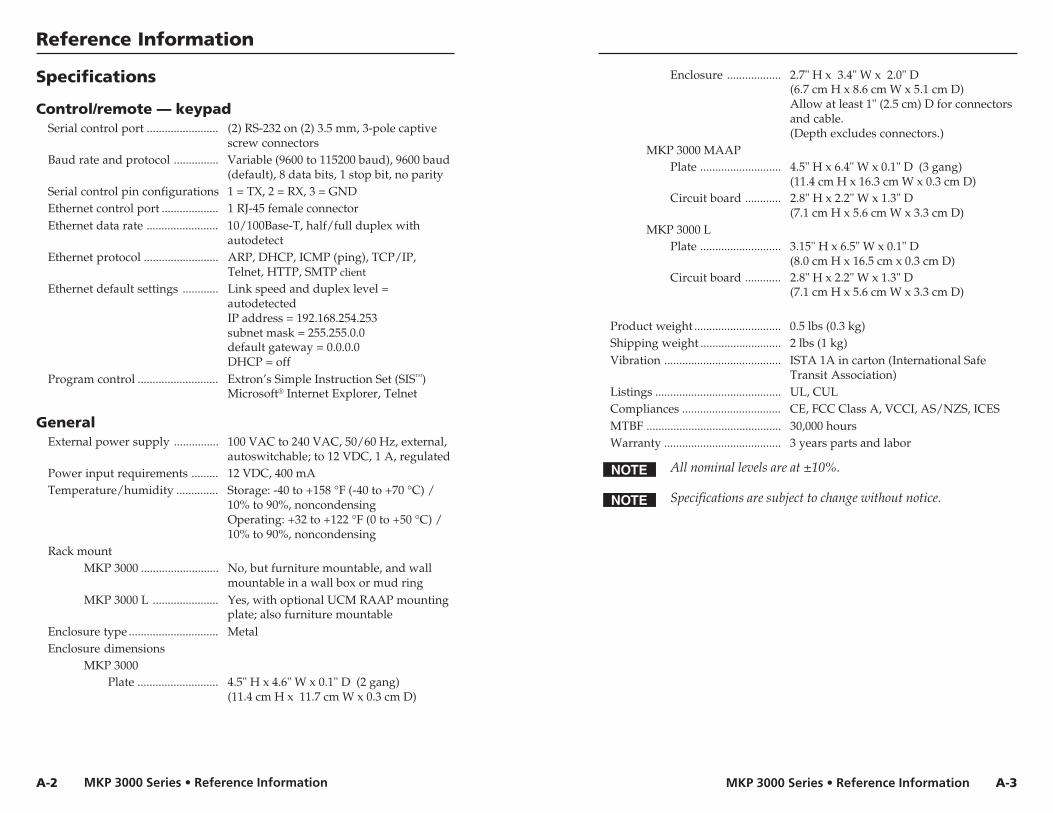
MKP 3000 Series • Reference InformationMKP 3000 Series • Reference Information
Reference Information
A-3
Enclosure .................. 2.7" H x 3.4" W x 2.0" D(6.7 cm H x 8.6 cm W x 5.1 cm D)Allow at least 1" (2.5 cm) D for connectorsand cable.(Depth excludes connectors.)
MKP 3000 MAAPPlate ........................... 4.5" H x 6.4" W x 0.1" D (3 gang)
(11.4 cm H x 16.3 cm W x 0.3 cm D)Circuit board ............ 2.8" H x 2.2" W x 1.3" D
(7.1 cm H x 5.6 cm W x 3.3 cm D)MKP 3000 L
Plate ........................... 3.15" H x 6.5" W x 0.1" D(8.0 cm H x 16.5 cm x 0.3 cm D)
Circuit board ............ 2.8" H x 2.2" W x 1.3" D(7.1 cm H x 5.6 cm W x 3.3 cm D)
Product weight ............................. 0.5 lbs (0.3 kg)Shipping weight ........................... 2 lbs (1 kg)Vibration ....................................... ISTA 1A in carton (International Safe
Transit Association)Listings .......................................... UL, CULCompliances ................................. CE, FCC Class A, VCCI, AS/NZS, ICESMTBF ............................................. 30,000 hoursWarranty ....................................... 3 years parts and labor
All nominal levels are at ±10%.
Specifications are subject to change without notice.
A-2
Specifications
Control/remote — keypadSerial control port ........................ (2) RS-232 on (2) 3.5 mm, 3-pole captive
screw connectorsBaud rate and protocol ............... Variable (9600 to 115200 baud), 9600 baud
(default), 8 data bits, 1 stop bit, no paritySerial control pin configurations 1 = TX, 2 = RX, 3 = GNDEthernet control port ................... 1 RJ-45 female connectorEthernet data rate ........................ 10/100Base-T, half/full duplex with
autodetectEthernet protocol ......................... ARP, DHCP, ICMP (ping), TCP/IP,
Telnet, HTTP, SMTP client
Ethernet default settings ............ Link speed and duplex level =autodetectedIP address = 192.168.254.253subnet mask = 255.255.0.0default gateway = 0.0.0.0DHCP = off
Program control ........................... Extron’s Simple Instruction Set (SIS™)Microsoft® Internet Explorer, Telnet
GeneralExternal power supply ............... 100 VAC to 240 VAC, 50/60 Hz, external,
autoswitchable; to 12 VDC, 1 A, regulatedPower input requirements ......... 12 VDC, 400 mATemperature/humidity .............. Storage: -40 to +158 °F (-40 to +70 °C) /
10% to 90%, noncondensingOperating: +32 to +122 °F (0 to +50 °C) /10% to 90%, noncondensing
Rack mountMKP 3000 .......................... No, but furniture mountable, and wall
mountable in a wall box or mud ringMKP 3000 L ...................... Yes, with optional UCM RAAP mounting
plate; also furniture mountableEnclosure type .............................. MetalEnclosure dimensions
MKP 3000Plate ........................... 4.5" H x 4.6" W x 0.1" D (2 gang)
(11.4 cm H x 11.7 cm W x 0.3 cm D)

MKP 3000 Series • Reference InformationMKP 3000 Series • Reference Information
Reference Information, cont’d
A-5A-4
-or-
CablesCables Part numbers
Comm-Link Cable Cut lengths:
50 feet (15.2 m) 26-461-01
100 feet (30 m) 26-461-02
200 feet (60 m) 26-461-03
300 feet (90 m) 26-461-05
400 feet (120 m) 26-461-04
Bulk spools:
500 feet (152 m) 22-119-02
1,000 feet (305 m) 22-119-03
Optional accessoriesAccessory Part number
MKP 10 MAAP Remote Keypad:Black 60-710-10White 60-710-20RAL 9010 white 60-710-50
PS 123 Rack mountable, multiple output 60-814-01Power Supply
UCM RAAP Universal Controller MountingRack kit:Black 70-344-02White 70-344-03
Part NumbersMKP 3000 Remote Control Panel Part number
MKP 3000, black 60-708-02
MKP 3000, white 60-708-03
MKP 3000, RAL 9010 white 60-708-05
MKP 3000 MAAP, black 60-709-02
MKP 3000 MAAP, white 60-709-03
MKP 3000 MAAP, RAL 9010 white 60-709-05
MKP 3000 L, black 60-709-22
Included partsThese items are included in each order for an MKP 3000:
Included parts Part number
12 VDC, 1A external power supply 70-055-01
MKP 3000 Series User’s Manual
Button label sheet
MR 200 two-gang mounting brackets(mud rings) for standard MKP 3000(black, white) 70-519-22, -23
MR 300 three-gang mounting brackets(mud rings) for MKP 3000 MAAP(black, white) 70-519-32, -33
Installation accessoriesAccessory Part number
Two-gang “J” box 2.5" deep 980084(for MKP 3000)
Three-gang “J” box 2.5" deep(for MKP 3000 MAAP) 980083
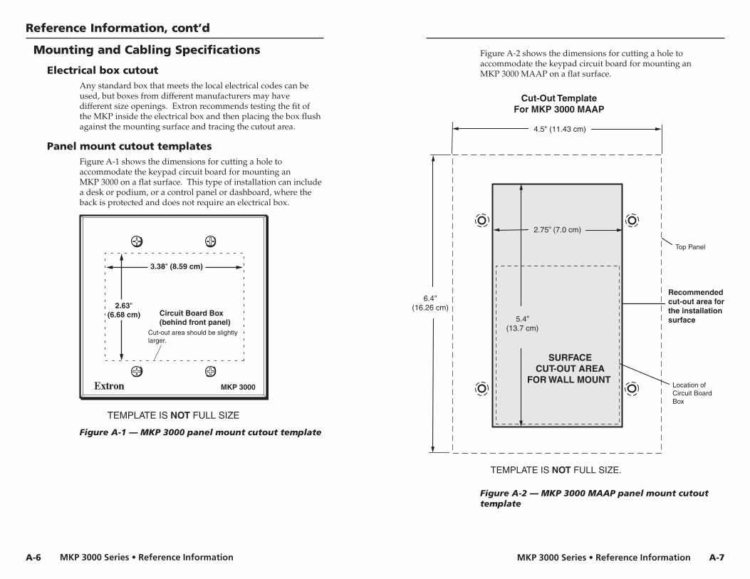
MKP 3000 Series • Reference InformationMKP 3000 Series • Reference Information
Reference Information, cont’d
Figure A-2 shows the dimensions for cutting a hole toaccommodate the keypad circuit board for mounting anMKP 3000 MAAP on a flat surface.
Figure A-2 — MKP 3000 MAAP panel mount cutouttemplate
A-7
Mounting and Cabling Specifications
Electrical box cutoutAny standard box that meets the local electrical codes can beused, but boxes from different manufacturers may havedifferent size openings. Extron recommends testing the fit ofthe MKP inside the electrical box and then placing the box flushagainst the mounting surface and tracing the cutout area.
Panel mount cutout templatesFigure A-1 shows the dimensions for cutting a hole toaccommodate the keypad circuit board for mounting anMKP 3000 on a flat surface. This type of installation can includea desk or podium, or a control panel or dashboard, where theback is protected and does not require an electrical box.
MKP 3000
VOLUME
I/O
2.63"(6.68 cm)
3.38" (8.59 cm)
TEMPLATE IS NOT FULL SIZE
Circuit Board Box(behind front panel)
Cut-out area should be slightlylarger.
Figure A-1 — MKP 3000 panel mount cutout template
A-6V
OL
UM
E
I/O
4.5" (11.43 cm)
6.4"(16.26 cm)
Location ofCircuit Board Box
2.75” (7.0 cm)
5.4”(13.7 cm)
Cut-Out TemplateFor MKP 3000 MAAP
TEMPLATE IS NOT FULL SIZE.
SURFACECUT-OUT AREA
FOR WALL MOUNT
Recommendedcut-out area forthe installationsurface
Top Panel

MKP 3000 Series • Reference InformationMKP 3000 Series • Reference Information
Reference Information, cont’d
A-8
TEXT
Separate twopiece button here.
Use notch toremove button.
Figure A-3 shows the dimensions for cutting a hole to mount anMKP 3000 L on a lectern or other flat surface.
Cut-Out TemplateFor MKP 3000 L
TEMPLATE IS NOT FULL SIZE.
Recommendedcut-out areafor the installationsurface.
Top Panel
6.15"(15.6 cm)
3.15" (8.0 cm)
SURFACECUT-OUT AREA
FOR MOUNTING
2.75" (7.0 cm)
5.50"(14.0 cm)
Position of Controller
Figure A-3 — MKP 3000 L panel mount cutouttemplate
Extron Comm-Link Control System cableWire specifications for Extron Comm-Link cable (figure A-4) areas follows:
A (red) = 18 American Wire Gauge (AWG)B (violet or blue) = 22 AWG (grouped and shielded)C (white) = 22 AWGD (drain) = 24 AWGE (black) = 18 AWG
Comm-Link cable was designed for use with MKPcontrol panels.
SuperFlex Plenum Jacket
Fiber Wrap
Two 22 AWG (White and Violet or Blue)One 24 AWGTinned Copper Drain Wire(foil-shielded group)
B, C
D
Two 18 AWG(Red and Black)
A, E
Figure A-4 — Extron Comm-Link cable
Changing Button LabelsThe MKP ships with default labels installed in the front panelbuttons (see figure 3-2, “Input/output selection mode labels”).It also includes a strip of alternate labels that you can insert inone or more of the mode selection buttons to make using theother modes clearer.
To change the labels in the MKP’s buttons,
1. Remove the button from the MKPby grasping the button firmly andpulling it away from the panel.
Various button models areavailable. Your buttons mayappear different.
2. Use a small screwdriver or ExtronTweeker to gently lever the buttoncap off of the white backing plate.
3. Insert a button label into the capand gently but firmly press thecap onto the white backing plate.
4. Press the button into place in the MKP.
A-9

MKP 3000 Series • Reference Information
Reference Information, cont’d
A-10