Embed Size (px)
Citation preview

Mk8 MM Expansion Features
Installation and Commissioning Guide


Mk8 MM
Expansion Features Installation and Commissioning Guide
Issued by: AUTOFLAME ENGINEERING LTD
Unit 1-2, Concorde Business Centre Airport Industrial Estate, Wireless Road
Biggin Hill, Kent TN16 3YN
Tel: +44 (0)845 872 2000 Fax: +44 (0)845 872 2010
Email: [email protected] Website: http://www.autoflame.com/
Registered Holder: Company: Department:
This manual and all the information contained herein is copyright of
Autoflame Engineering Ltd. It may not be copied in the whole or part without the consent of the Managing Director.
Autoflame Engineering Ltd’s policy is one of continuous improvement in both design and manufacture. We therefore reserve the right to amend
specifications and/or data without prior notice. All details contained in this manual are correct at the time of going to print.


Important Notes
A knowledge of combustion related procedures and commissioning is essential before embarking work on any of the M.M./E.G.A. systems. This is for safety reasons and effective use of the M.M./ E.G.A. system. Hands on training is required. For details on schedules and fees relating to group training courses and individual instruction, please contact the Autoflame Engineering Ltd. offices at the address listed on the front.
Short Form - General Terms and Conditions
A full statement of our business terms and conditions are printed on the reverse of all invoices. A copy of these can be issued upon application, if requested in writing.
The System equipment and control concepts referred to in this Manual MUST be installed, commissioned and applied by personnel skilled in the various technical disciplines that are inherent to the Autoflame product range, i.e. combustion, electrical and control.
The sale of Autoflame’s systems and equipment referred to in this Manual assume that the dealer, purchaser and installer has the necessary skills at his disposal. i.e. A high degree of combustion engineering experience, and a thorough understanding of the local electrical codes of practice concerning boilers, burners and their ancillary systems and equipment.
Autoflame’s warranty from point of sale is two years on all electronic systems and components. One year on all mechanical systems, components and sensors.
The warranty assumes that all equipment supplied will be used for the purpose that it was intended and in strict compliance with our technical recommendations. Auto-flame’s warranty and guarantee is limited strictly to product build quality, and design. Excluded absolutely are any claims arising from misapplication, incorrect installation and/or incorrect commissioning.

Contents 1 TECHNICAL SPECIFICATIONS ................................................................................... 1
1.1 Mk8 Expansion Board ............................................................................................................. 1
1.2 Expansion Board Inputs and Outputs ...................................................................................... 2
1.2.1 Fuse Ratings ..................................................................................................................... 2
1.3 Cable Specifications ................................................................................................................ 3
1.4 Expansion Board Terminals Description .................................................................................. 4
2 EXPANSION OPTIONS ............................................................................................ 7
3 WATER LEVEL CONTROL ........................................................................................ 25
3.1 Overview .............................................................................................................................. 25
3.1.1 Safety ........................................................................................................................... 25
3.1.2 Autoflame Water Level Control .................................................................................... 25
3.1.3 Water Treatment ........................................................................................................... 26
3.2 Water Valve ......................................................................................................................... 27
3.2.1 Specifications ................................................................................................................ 27
3.2.2 Feed Water Valve Sizing .............................................................................................. 28
3.2.3 Feed Water Control ...................................................................................................... 29
3.3 Ways of Level Sensing .......................................................................................................... 30
3.3.1 Overview ...................................................................................................................... 30
3.3.2 Configuration ................................................................................................................ 31
3.4 Capacitance Probes .............................................................................................................. 35
3.4.1 Overview ...................................................................................................................... 35
3.4.2 Operation ..................................................................................................................... 36
3.4.3 Specification ................................................................................................................. 36
3.4.4 Installation Safety Guidelines ....................................................................................... 39
3.4.5 Capacitance Probe – Externally Mounted Pots ............................................................ 40
3.4.6 Capacitance Probe – Internally Mounted Pots ............................................................. 42
3.4.7 Capacitance Probe – Installation for a Water Tube Boiler ........................................... 44
3.4.8 External Probe Chamber Dimensions ........................................................................... 45
3.4.9 Configuration ................................................................................................................ 46
3.5 2nd Low Probe ........................................................................................................................ 47
3.5.1 Overview ...................................................................................................................... 47
3.5.2 Operation ..................................................................................................................... 48
3.5.3 Specifications ................................................................................................................ 48
3.5.4 Installation and Safety Guidelines ................................................................................ 50
3.5.5 Configuration ................................................................................................................ 51

3.6 External Level Sensor ........................................................................................................... 52
3.7 Auxiliary Alarm Inputs .......................................................................................................... 53
3.8 Commissioning Procedure .................................................................................................... 54
3.8.1 Commissioning Checks .................................................................................................. 54
3.8.2 Levels ............................................................................................................................ 54
3.8.3 Setting End of Probe Level ............................................................................................ 55
3.8.4 Setting 2nd Low Level ..................................................................................................... 57
3.8.5 Setting 1st Low Level ...................................................................................................... 58
3.8.6 Setting Control Point Level ............................................................................................ 59
3.8.7 Setting HIGH Level ....................................................................................................... 60
3.8.8 Save Commissioning ..................................................................................................... 61
3.8.9 Operational Checks ...................................................................................................... 63
3.8.10 Adjust Control Point ...................................................................................................... 64
3.9 Water Level Control Functions .............................................................................................. 65
3.9.1 Pre-Alarms .................................................................................................................... 65
3.9.2 Pump Bypass ................................................................................................................. 65
3.9.3 Test Outputs and Shunt Switch ...................................................................................... 66
3.9.4 Sudden Pressure Drop .................................................................................................. 67
3.10 Faults .................................................................................................................................... 68
4 TOP BLOWDOWN ................................................................................................. 71
4.1 Overview .............................................................................................................................. 71
4.1.1 Importance of Maintaining TDS .................................................................................... 71
4.1.2 TDS, Conductivity and Temperature ............................................................................. 72
4.2 TDS Valve ............................................................................................................................. 73
4.3 TDS Probe ............................................................................................................................. 74
4.3.1 Specification ................................................................................................................. 74
4.3.2 Dimensions .................................................................................................................... 75
4.3.3 Installation .................................................................................................................... 76
4.3.4 Configuration ................................................................................................................ 77
4.4 Ways of Controlling TDS Level ............................................................................................. 78
4.4.1 Continuous TDS Control ................................................................................................ 78
4.4.2 Solenoid and Servomotor 2-State TDS Control ............................................................. 78
4.4.3 TDS Timing Diagram ..................................................................................................... 79
4.4.4 Sample Routine ............................................................................................................. 80
4.5 Calibrating TDS Probe .......................................................................................................... 81
4.6 Faults .................................................................................................................................... 83
5 BOTTOM BLOWDOWN .......................................................................................... 84

5.1 Overview .............................................................................................................................. 84
5.2 Bottom Blowdown Reduction ................................................................................................ 85
5.2.1 Blowdown Savings ........................................................................................................ 85
5.2.2 Calculation for Bottom Blowdown Reduction ................................................................ 86
5.3 Installation Guidance ............................................................................................................ 88
5.3.1 Bottom Blowdown Valve ............................................................................................... 88
5.3.2 Bottom Blowdown Module ........................................................................................... 89
5.4 Set-up .................................................................................................................................... 92
5.4.1 Bottom Blowdown Settings ............................................................................................ 92
5.4.2 Setting Servomotor ....................................................................................................... 93
5.5 Bottom Blowdown Configuration .......................................................................................... 97
5.5.1 Bottom Blowdown Log .................................................................................................. 99
5.6 Faults .................................................................................................................................. 100
6 DRAUGHT CONTROL ........................................................................................... 101
6.1 Overview ............................................................................................................................ 101
6.1.1 Benefits of Draught Control ........................................................................................ 101
6.1.2 Fully Integrated Draught Control ................................................................................ 101
6.2 Draught Control Operation ................................................................................................ 103
6.2.1 Overview .................................................................................................................... 103
6.2.2 Deactivation Window ................................................................................................. 103
6.2.3 Draught Control Trim .................................................................................................. 105
6.3 Set-Up ................................................................................................................................. 107
6.3.1 Configuration .............................................................................................................. 107
6.3.2 Ways of Using Draught Servomotor ........................................................................... 108
6.4 Commissioning Draught Control ......................................................................................... 109
6.4.1 Commissioning Checks ................................................................................................ 109
6.4.2 Commissioning Screen ................................................................................................ 110
6.5 Faults .................................................................................................................................. 111
7 REMOTE CONTROL .............................................................................................. 112
7.1 Overview ............................................................................................................................ 112
7.2 Configuration ...................................................................................................................... 113
7.3 Modbus Addresses ............................................................................................................. 114
8 FIRST OUTS ......................................................................................................... 123
8.1 Overview ............................................................................................................................ 123
8.2 Configuration ...................................................................................................................... 124
8.2.1 Running Interlock Circuit ............................................................................................. 124
8.2.2 Interlock Option .......................................................................................................... 128
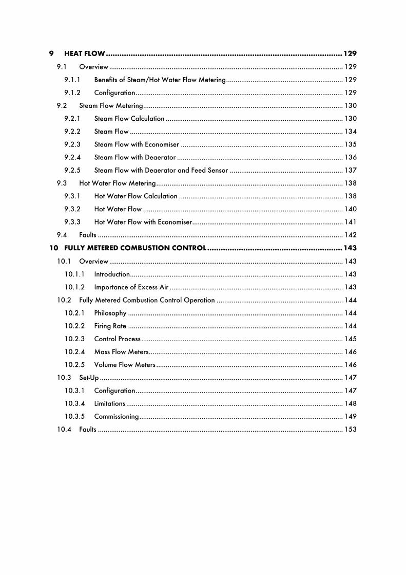
9 HEAT FLOW ......................................................................................................... 129
9.1 Overview ............................................................................................................................ 129
9.1.1 Benefits of Steam/Hot Water Flow Metering .............................................................. 129
9.1.2 Configuration .............................................................................................................. 129
9.2 Steam Flow Metering .......................................................................................................... 130
9.2.1 Steam Flow Calculation .............................................................................................. 130
9.2.2 Steam Flow ................................................................................................................. 134
9.2.3 Steam Flow with Economiser ...................................................................................... 135
9.2.4 Steam Flow with Deaerator ........................................................................................ 136
9.2.5 Steam Flow with Deaerator and Feed Sensor ............................................................ 137
9.3 Hot Water Flow Metering ................................................................................................... 138
9.3.1 Hot Water Flow Calculation ....................................................................................... 138
9.3.2 Hot Water Flow .......................................................................................................... 140
9.3.3 Hot Water Flow with Economiser ................................................................................ 141
9.4 Faults .................................................................................................................................. 142
10 FULLY METERED COMBUSTION CONTROL ............................................................ 143
10.1 Overview ............................................................................................................................ 143
10.1.1 Introduction ................................................................................................................. 143
10.1.2 Importance of Excess Air ............................................................................................ 143
10.2 Fully Metered Combustion Control Operation ................................................................... 144
10.2.1 Philosophy .................................................................................................................. 144
10.2.2 Firing Rate .................................................................................................................. 144
10.2.3 Control Process ........................................................................................................... 145
10.2.4 Mass Flow Meters ....................................................................................................... 146
10.2.5 Volume Flow Meters ................................................................................................... 146
10.3 Set-Up ................................................................................................................................. 147
10.3.1 Configuration .............................................................................................................. 147
10.3.4 Limitations ................................................................................................................... 148
10.3.5 Commissioning ............................................................................................................ 149
10.4 Faults .................................................................................................................................. 153


1 Technical Specifications
04.09.2016 Mk8 MM Expansion Features Installation and Set-Up Guide Page 1
1 TECHNICAL SPECIFICATIONS
1.1 Mk8 Expansion Board

1 Technical Specifications
Page 2 Mk8 MM Expansion Features Installation and Set-Up Guide 04.09.2016
1.2 Expansion Board Inputs and Outputs
Outputs: 120/230 V All outputs with the exception of PF are switched neutrals
BFW 250mA Must be connected through contactor
BB 250mA Must be connected through contactor
HWV 100mA (alarm indicator)
2LA 100mA (alarm indicator)
2LV 100mA (alarm indicator)
H1A 100mA (alarm indicator)
1LV 100mA (alarm indicator)
79 100mA (alarm indicator on MM board)
TB 250mA Solenoid only, must be connected through contactor
PF Maximum 2A (load currents for above terminals)
Note: Max number of alarm indicators on at any time is 3 (1LV, 2LA, 2LV)
Main Voltage Signal Inputs: At 120V current loading is approximately maximum 0.7mA per input. At 230V current loading is approximately maximum 1.5mA per input. 1.2.1 Fuse Ratings
Fuse Rating Spare Part Number1 6.3A (T) FU10026
Fuse 1 protects the mains input to the MM, including the mains output terminals 50 – 64.
2 2A (T) FU10034
Fuse 2 protects the power supply (terminal 69) for the servomotors, alarm and 2 port valve. If this fuse blows, the error ‘Triac Power Supply Error (Check F2)’ will occur.
3 500mA FU10040
Fuse 3 protects the 13.5V power supply to the oil pressure sensor and IR scanner on terminal 49. If this fuse blows, the error ‘Fused 13.5V Supply Error (Check F3)’ will occur.
4 500mA 500mA
Fuse 5 protects the power supply (terminal PF) for the expansion servos and alarm outputs. If fuse 5 blows, the error ‘Expansion PF Output (Check F5)’ will occur.
5 2A (T) FU10034
Fuse 5 protects the power supply (terminal PF) for the expansion servos and alarm outputs. If fuse 5 blows, the error ‘Expansion PF Output (Check F5)’ will occur.
6 2A FU10027
Fuse 6 protects the DC circuits. If this fuse blows, the display will be off and both LEDs adjacent to fuse 7 and 8 will be off.
7 4A FU10050
Fuse 7 protects the internal 5V supply. If this fuse blows the display will be off and the LED adjacent to the fuse will be off.
8 2.5A FU10042
Fuse 8 protects the internal 12V supply. If this fuse blows the display will be off and the LED adjacent to the fuse will be off.
1 Technical Specifications
04.09.2016 Mk8 MM Expansion Features Installation and Set-Up Guide Page 3
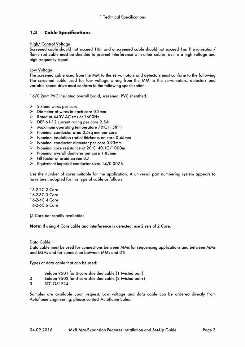
1.3 Cable Specifications
High/ Control Voltage Screened cable should not exceed 10m and unscreened cable should not exceed 1m. The ionisation/ flame rod cable must be shielded to prevent interference with other cables, as it is a high voltage and high frequency signal. Low Voltage The screened cable used from the MM to the servomotors and detectors must conform to the following The screened cable used for low voltage wiring from the MM to the servomotors, detectors and variable speed drive must conform to the following specification: 16/0.2mm PVC insulated overall braid, screened, PVC sheathed. Sixteen wires per core Diameter of wires in each core 0.2mm Rated at 440V AC rms at 1600Hz DEF 61-12 current rating per core 2.5A Maximum operating temperature 70oC (158oF) Nominal conductor area 0.5sq mm per core Nominal insulation radial thickness on core 0.45mm Nominal conductor diameter per core 0.93mm Nominal core resistance at 20oC. 40.1Ω/1000m Nominal overall diameter per core 1.83mm Fill factor of braid screen 0.7 Equivalent imperial conductor sizes 14/0.0076 Use the number of cores suitable for the application. A universal part numbering system appears to have been adopted for this type of cable as follows: 16-2-2C 2 Core 16-2-3C 3 Core 16-2-4C 4 Core 16-2-6C 6 Core (5 Core not readily available) Note: If using 4 Core cable and interference is detected, use 2 sets of 2 Core. Data Cable Data cable must be used for connections between MMs for sequencing applications and between MMs and EGAs and for connection between MMs and DTI Types of data cable that can be used: 1 Beldon 9501 for 2-core shielded cable (1 twisted pair) 2 Beldon 9502 for 4-core shielded cable (2 twisted pairs) 3 STC OS1P24 Samples are available upon request. Low voltage and data cable can be ordered directly from Autoflame Engineering, please contact Autoflame Sales.

1 Technical Specifications
Page 4 Mk8 MM Expansion Features Installation and Set-Up Guide 04.09.2016
1.4 Expansion Board Terminals Description
S All terminals marked S are internally connected. They are provided for connections to the various screened cables.
P- 0V supply to top blowdown and feed water servomotors
FW Signal from feed water servomotor, indicating position
P+ +12V supply to top blowdown and feed water servomotors
- Common for terminals T1, T2 and T3
T1 Signal input from T1 temperature sensor
T2 Signal input from T2 temperature sensor
- Common for terminal T1, T2 and T3
T3 Signal input from T3 temperature sensor
TW Signal from top blowdown servomotor, indicating position
F- Common for terminals MF and CF
MF Current input, 4-20mA for cold water make up flow meter
CF Current input, 4-20mA for condensate return flow meter
I+ Current output, 4-20mA to feed water VSD
V+ Voltage output, 0-10V to feed water VSD
IV- Common for terminals I+ and V+
EX- Common for terminal EX+
EX+ Current input, 4-20mA for external water level probe or fuel flow feedback
DT+, DT- Digital communications from draught control pressure sensor
DP- 0V supply to draught control pressure sensor and draught control servomotor
DP+ +12V supply to draught control pressure sensor and draught control servomotor
DPW Signal from draught control servomotor, indicating position
5T+, 5T- Digital communications from bottom blowdown module and 2nd low probe
4P- 0V supply to 2nd low resistance probe
4P+ +12V supply to 2nd low resistance probe
6T+, 6T- Communications port connections I/O module RS485
3P+ +9V supply to TDS probe

1 Technical Specifications
04.09.2016 Mk8 MM Expansion Features Installation and Set-Up Guide Page 5
3P- 0V supply to TDS probe
3T+, 3T- Digital communication connections from TDS probe
1P+ +9V supply to capacitance probe 1
1P- 0V supply to capacitance probe 1
1T+, 1T- Digital communications connections from capacitance probe 1
2P+ +9V supply to capacitance probe 2
2P- 0V supply to capacitance probe 2
2T+, 2T- Digital communications connections from capacitance probe 2
FO1 First Out annunciation line voltage input 1
FO2 First Out annunciation line voltage input 2
FO3 First Out annunciation line voltage input 3
FO4 First Out annunciation line voltage input 4
FO5 First Out annunciation line voltage input 5
FO6 First Out annunciation line voltage input 6
FO7 First Out annunciation line voltage input 7
FO8 First Out annunciation line voltage input 8
FO9 First Out annunciation line voltage input 9
FO10 First Out annunciation line voltage input 10
FO11 First Out annunciation line voltage input 11
FO12 First Out annunciation line voltage input 12
PF Power feed 2A output (230V/110)
FO13 First Out annunciation line voltage input 13
FO14 First Out annunciation line voltage input 14
FO15 First Out annunciation line voltage input 15
HAI External high water auxiliary input
1AI External 1st low water auxiliary input
2AI External 2nd low water auxiliary input
M/R System alarm mute/reset
TST System test alarm inputs/ shunt switch

1 Technical Specifications
Page 6 Mk8 MM Expansion Features Installation and Set-Up Guide 04.09.2016
NC Unused – do not connect
TB Switched neutral – top blowdown contactor
TBI Switched neutral – drives top blowdown servomotor clockwise
1LV Switched neutral – 1st low water visual alarm
H1A Switched neutral – 1st low/ high water audible alarm
2LV Switched neutral – 2nd low water visual alarm
2LA Switched neutral – 2nd low water audible alarm
HWV Switched neutral – High water visual alarm
BB Switched neutral – Bottom blowdown contactor
BFW Switched neutral – Feed water pump contactor
MVI Switched neutral – drives feed water servomotor clockwise
MVD Switched neutral – drives feed water servomotor counter clockwise
TBD Switched neutral – drives top blowdown servomotor counter clockwise
DCI Switched neutral – drives draught control servomotor clockwise
DCD Switched neutral – drives draught control servomotor counter clockwise

2 Expansion Options
04.09.2016 Mk8 MM Expansion Features Installation and Set-Up Guide Page 7
2 EXPANSION OPTIONS
The Options, Parameters and Expansion Options must only be changed by factory trained and certified technicians who have a thorough appreciation of the Autoflame combustion systems and the combustion process in general. Any person changing these settings without the correct factory training and understanding of the boiler plant may place themselves and others in a potentially dangerous situation.
CH1, CH2, CH3, CH4, CH5, CH6 and CH7 refer to the rows of buttons respectively start with CH1 at the top. The options, parameters and expansion options are all viewable while the MM is in run mode. In commissioning mode, all of the options, parameters and expansion options can be adjusted according to the application. Non safety-critical options, parameters and expansion options can be adjusted through Online Changes.
Press in the Commission Mode screen to access the Expansion Options. Any number of expansion options can be changed at on time. By pressing WLC, TBD, BBD, DC, Modbus FO and Flow at the bottom of the screen, the expansion options can be grouped together by feature. When the changes have been made to suit the application’s needs, press Exit to go back to the Commission Mode screen. To set all the options, parameters and expansion options to the default values and erase the commissioning data, set option/ parameter 160 to 5. The MM will then automatically restart. Note: The Expansion Feature must be unlocked by sending the code for that MM via Download Manager. Please see PC Software Guide on unlocking Expansion Features. Unlockable Software Feature Part Number Autoflame Water Level MK8001 Analogue Water Level (requires Autoflame Water Level) MK8002 Top Blowdown MK8003 Bottom Blowdown MK8004 Draught Control MK8005 Direct Modbus MK8006 First Out Annunciation MK8007 Fully Metered Combustion System MK8008 Heat Flow (Steam Flow + Hot Water Flow) MK8009

2 Expansion Options
Page 8 Mk8 MM Expansion Features Installation and Set-Up Guide 04.09.2016
Exp Option
Default Range Description
1 0 Water Level Control Function Expansion feature 1 must be unlocked on the MM For setting 1, there must
be a minimum of two level sensing elements or a conflict will appear. For the possible water level sensing device combinations, please see section 3.3. The capacitance probes with/without external level sensor will be commissioned at end of probe, second low, first low, control point and high water.
0 Water level control disabled 1 Water level control enabled
2 0 Feedwater Control Element The feedwater pump will turn on and off at the according to the levels set
relative to the control point, through expansion options 10, 11 and 12. For setting 0, water going to the boiler is only controlled by the feedwater pump output terminal BFW. For settings 1 and 2 the MM controls the feedwater via a PID loop, see expansion options 13, 14, 15, and 16. For setting 1 the MM uses the servomotor on terminals P-, FW, P+, MVI and MVD. For setting 2 the MM uses the VSD on terminals I+, V+ and IV-.
0 Pump on/off only 1 Pump on/off and servomotor control 2 Pump on/off and VSD control
3 0 Capacitance Probes If water level control is enabled, the MM will require a minimum of two
level sensing elements. For the possible water level sensing device combinations, please see section 3.3.
0 Capacitance probes disabled 1 One capacitance probe 2 Two capacitance probes
4 0 External Level Sensor The external level sensor is wired to terminals EX- and EX+ and will give a
4-20mA signal. The readings can be scaled in expansion options 30 and 31. If an external level sensor is used, then a 4-20mA signal for fuel flow feedback cannot be enabled (option 57) and fully metered combustion control cannot be enabled (expansion option 140). For the possible water level sensing device combinations, please see section 3.3.
0 Disabled 1 Enabled
5 0 Auxiliary Alarm Inputs For setting 1, the auxiliary alarm mains inputs terminals HAI, 1AI and 2AI
are used in addition to the capacitance probes with/without external level sensor readings. For the possible water level sensing device combinations, please see section 3.3.
0 Auxiliary alarm inputs disabled 1 Auxiliary alarm inputs enabled
6 0 Second Low Probe For setting 0, it is recommended that an auxiliary second low mains input is
wired to terminals 2AI. For setting 1, the Autoflame conductive second low probe is wired to terminals 4P-, 4P+, 6T- and 6T-. Please see local codes/ regulations for second low probe and auxiliary second low alarm setup. For the possible water level sensing device combinations, please see section 3.3.
0 Second low probe disabled 1 Second low probe enabled

2 Expansion Options
04.09.2016 Mk8 MM Expansion Features Installation and Set-Up Guide Page 9
Exp Option
Default Range Description
7 0 Pre-High Alarm Percentage The pre-high alarm level is at percentage between the control point and
high water, with the control point being referring to 0% and the high water referring to 100%. For setting 0 there is no pre-high alarm and for settings higher than 1, the MM will generate an alarm if the water level reaches this % value between the commissioned control point and high water. For example, if this is set to 45%, then a pre-high alarm will occur if the water level rises to 45% between the control point and high water level.
0 Disabled 1 – 99 1% - 99%
8 0 Pre-First-Low Alarm Percentage The pre-first-low alarm level is at percentage between the control point and
first low, with the control point being referring to 0% and the first low referring to 100%. For setting 0 there is no pre-first-low alarm and for settings higher than 1, the MM will generate an alarm if the water level reaches this % value between the commissioned control point and first low. For example, if this is set to 45%, then a pre-first-low alarm will occur if the water level drops to 45% between the control point and first low level.
0 Disabled 1 – 99 1% - 99%
9 0 Burner Operation at High Water For setting 0, the burner will continue to fire at high water. For setting 1 the
burner will stop firing at high water. Expansion option 10 sets whether the pump turns off above the control point or high water.
0 Burner runs at high water 1 Burner stops at high water
10 0 Pump Turn Off Point The water level at which the pump turns off is set as a percentage above
the control point for setting 0, or above the high water for setting 1, see expansion option 11.
0 Pump turns off above control point 1 Pump turns off above high water
11 30 Pump Turn Off Percentage When the water level reaches this percentage of the control point or high
water, depending on how expansion option 11 is set, the pump will turn off. If expansion option 11 is set to 0, then this percentage will be between the control point and high water. If expansion option 11 is set to 1, then then this percentage is above high water, and should not be set more than a safe top of the probe level.
0 – 100 0% - 100%
12 10 Pump Turn On Percentage When the water level drops the control point, the pump will turn on
at this percentage in between the control point and first low. 0 – 100 0% - 100%

2 Expansion Options
Page 10 Mk8 MM Expansion Features Installation and Set-Up Guide 04.09.2016
Exp Option
Default Range Description
13 50 Feedwater Control Proportional Band The proportional band is set as a percentage between the control point and
first low where the PID control will make corrections to the feedwater going to the boiler to maintain the control point. The feedwater control will act on servomotor or VSD depending on how expansion option 2. The control point represents 0% and first low represents 100%, so it is possible to set the feedwater control proportional band to a water level below the first low. If the water level is outside of the proportional band, then the feedwater servomotor will remain fully open.
0 Disabled 1 – 200 1% - 200%
14 20 Feedwater Control Integral Time The integral element in the feedwater control will make corrections to the
feedwater via the servomotor or VSD, depending on expansion option 2. For a slower response, increase the integral time. For a quicker response in critical steam applications to avoid the water level reaching first low, decrease the integral time. However if overshoot occurs and the water level rises to above the control point and this is not desired, then the derivative element will need to be enabled, see expansion option 15.
0 Disabled 1 – 1000 Seconds
15 0 Feedwater Control Derivative Time The derivative element in the feedwater control is suitable for applications
requiring a quick response but the water level should not rise too high above the control point. For example, if the burner is set to stop firing at high water in expansion option 9 and high water is commissioned not too far above from control point, then overshoot is undesirable in a critical steam application, as the burner would stop firing.
0 Disabled 1 – 1000 Seconds
16 900 Feedwater Servo Open Angle The feedwater servomotor closed position is set by zeroing the
potentiometer in commissioning mode. As default the servomotor is set as fully open, however this setting can be decreased to shorten the operational movement range of the servomotor.
100 – 900 10.0O – 90.0O
17 0 Pump Bypass Operation The pump bypass (terminal TB) will turn on at the switch point set as a % of
the open range of the valve, and will turn off at an offset from the switch point, set as the bypass hysteresis, see expansion options 18 and 19. However if the pump is turned off, then the pump bypass will also be turned off. For setting 1, the pump bypass hysteresis is below the switch point, so the pump bypass will turn off at an offset below the switch point. For setting 2, the pump bypass hysteresis is above the switch point, so the pump bypass will turn off at an offset above the switch point.
0 Pump bypass disabled 1 Pump bypass on above switch point 2 Pump bypass on below switch point
18 20 Pump Bypass Switch Point The bump bypass switch point is set as a percentage of the valve open
range set in expansion option 16. 5 – 95 5% - 95%

2 Expansion Options
04.09.2016 Mk8 MM Expansion Features Installation and Set-Up Guide Page 11
Exp Option
Default Range Description
19 5 Pump Bypass Hysteresis The pump bypass hysteresis is set at percentage from the pump bypass
switch point set in expansion option 18, and this will below the switch point for expansion option set to 1 (pump bypass on above switch point) and above the switch point for expansion option set to 2 (pump bypass on below switch point).
0 Disabled 1 – 50 1% - 50%
20 0 Burner Operation on Feedwater Control Fault For setting 0, the burner will continue to fire if there is a feedwater fault. For
setting 1 the burner will stop firing if there is a feedwater fault. If the burner continues to fire and the water level drops below the control point to first low, an alarm will occur and the burner will stop firing.
0 Burner runs on feedwater control fault 1 Burner stops on feedwater control fault
21 1 Function of Test Input The test input terminal TST can be set for checking the auxiliary alarm
outputs or shunt switch. For setting 0, hold the test input continuously to cycle through alarm outputs every two seconds. For setting 1, hold the test input for three seconds to trigger the shunt switch operation, and to cancel the shunt switch operation, hold the test input for a further three seconds. See expansion options 22 and 23 for the shunt switch timings.
0 Test input operates alarm outputs test 1 Test input operates shunt switch
22 300 Shunt Switch – Time to 1st Low When the shunt switch test is activated in expansion option 21, there is time
delay for the water to reach the first low level, allowing the operator to decrease the water level. This test checks the first low alarm while the burner continues to operate. If water does not drop to the first low level in this time period, then MM will revert back to normal run mode and cancel the shunt switch test.
30 – 600 Seconds
23 300 Shunt Switch – Time to 2nd Low After the shunt switch has been tested for first low, there is further time
delay for the water to reach the second low level, allowing the operator to further decrease the water level. This test checks the second low alarm while the burner continues to operate. If water does not drop to the second low level in this time period, the burner will turn off.
30 – 600 Seconds
24 5 Sudden Pressure Drop Trigger Rate If the pressure drops by this value set over 3 seconds to a pressure below
the reset offset from the required pressure setpoint set in expansion option 26, then a sudden pressure drop condition is detected and the control point will increase by a percentage set in expansion option 25.
1 – 100 PSI or 0.1 bar or 0.01 bar for low pressure sensor (depends on load detector set in option 1 and metric/imperial units set in parameter 40)

2 Expansion Options
Page 12 Mk8 MM Expansion Features Installation and Set-Up Guide 04.09.2016
Exp Option
Default Range Description
25 25 Sudden Pressure Drop Control Point Increase If a sudden pressure drop is detected, the water level control point will
increase to the percentage of the control point set. Once the steam pressure increases to the reset offset value from the required pressure setpoint, the control point will return to the commissioned value. See expansion options 24 and 26.
0 Disabled 1 – 75 1% - 75%
26 10 Sudden Pressure Drop Reset Offset If the pressure drops by the value set in expansion option 24 over 3
seconds to a pressure below this reset offset from the required pressure setpoint, then a sudden pressure drop condition is detected and the control point will increase by a percentage set in expansion option 25.
0 Disabled 1 – 100 PSI or 0.1 bar or 0.01 bar for low pressure sensor (depends on load
detector set in option 1 and metric/imperial units set in parameter 40)
27 20 Probe Mismatch Threshold The probe mismatch threshold is a percentage of the first low. If the probes
and/or external level sensors read a difference in the level greater than this value set for 30 seconds, then a probe mismatch alarm will occur.
5 – 100 5% - 100%
28 3 Capacitance Probe Still Water Threshold This threshold set is the distance between the high peak and low peak of
the water wave signature. If the capacitance probes detect a reading between the high peak and low peak which is less than this value for 30 seconds while the burner is firing, a capacitance probe still water alarm will occur.
0 Disabled 1 – 100 1 – 100mm or 0.0 – 3.9” (see parameter 40)
29 10 Capacitance Probe Filter Time The filter time is the rolling time period over which the capacitance probes
take the water level reading. When a moving water level is detected this time period reduces in proportion linearly to the movement.
1 – 30 Seconds
30 0 External Level Sensor Scaling If an external level sensor is set in expansion option 4, then the 4-20mA
signal will need be scaled for the length of the sensor. 0 Disabled 1 – 20000 0.01 – 200.00mm/mA or 0.01 – 200.00”/mA (see parameter 40)
31 10 External Level Sensor Filter Time The filter time is the rolling time period over which the external level sensor
takes the water level reading. When a moving water level is detected this time period reduces in proportion linearly to the movement.
1 – 30 Seconds
32 3 Wave Signature Average Level The wave signature average level is set as percentage of the wave
signature height of the water level. 0 – 10 0 – 100% (value 3 = 30%)

2 Expansion Options
04.09.2016 Mk8 MM Expansion Features Installation and Set-Up Guide Page 13
Exp Option
Default Range Description
33 - Unused
34 - Unused
35 - Unused
36 - Unused
37 - Unused
38 - Unused
39 - Unused
40 0 Top Blowdown Function To enable top blowdown, the top blowdown expansion feature must be
unlocked. The TDS value in the water, measured by the TDS probe on terminals 3P+, 3P-, 3T+ and 3T-, is maintained by a PID loop, see expansion options 52, 53 and 54. For setting 1, the terminal TB output will open and close an external solenoid valve. For setting 2, the top blowdown valve is open and closed via a top blowdown servomotor on terminals P-, FW, P+, TBI and TBD. For setting 3, continuous top blowdown management is enabled for the top blowdown.
0 Top blowdown disabled 1 Top blowdown using solenoid 2 Top blowdown using servo (2-state) 3 Top blowdown using servo (continuous)
41 0 TDS Units The TDS units can be displayed in ppm or μS/cm. 0 Concentration in ppm 1 Conductivity in μS/cm
42 2500 TDS Target This is the set TDS target value which the TDS control will try to maintain by
open and closing the solenoid or top blowdown valve, see expansion option 40. The target TDS value should be set according to the boiler manufacturer’s guidelines.
50 – 9999 ppm or μS/cm (see expansion option 41)
43 180 TDS Temperature Compensation The steam temperature is calculated from the steam pressure sensor
reading. The TDS value read will be corrected by the % per OC set, for the difference between the steam temperature and 25 degrees OC, so the TDS measured value displayed is shown corrected to 25 degrees OC. This temperature compensation coefficient will depend on the contaminants in the water and should be set accurately for the contaminants that make up the TDS in the water.
20 – 1000 0.20 – 10.00% per OC
44 65 TDS PPM Conversion The ppm to μS/cm conversion coefficient will depend on the contaminants
in the water and should be set accurately for the contaminants that make up the TDS in the water.
20 – 100 0.20 – 1.00ppm / ( μS/cm)

2 Expansion Options
Page 14 Mk8 MM Expansion Features Installation and Set-Up Guide 04.09.2016
Exp Option
Default Range Description
45 1000 TDS Adjustment This value will automatically display the adjustment factor when the TDS
probe is recalibrated during running. 10 – 999 0.010 – 9.999
46 0 TDS Warning Level The TDS warning level is an absolute limit; if the average TDS reading
taken from the measurement time is higher than this TDS limit, a warning will be generated. This limit should not be set lower than the target TDS value set in expansion option 42.
0 Disabled 1 – 5000 ppm or μS/cm (see expansion option 41)
47 10 Pressure Threshold This pressure threshold is an offset below the required pressure setpoint. If
the actual pressure is below this offset pressure, then TDS control will not operate.
0 Disabled 1 – 100 PSI or 0.1 bar or 0.01 bar for low pressure sensor (depends on load
detector set in option 1 and metric/imperial units set in parameter 40)
48 25 Sample Time The first stage of the TDS control cycle is the sample time, where the
solenoid valve or top blowdown servomotor is fully opened to take a sample.
2 – 60 Seconds
49 25 Settle Time The second stage of the TDS control cycle is the settle time. Following taking
a sample time in expansion option 48, the solenoid valve or top blowdown servomotor goes fully closed to allow the sample to stabilise for this settle time.
2 – 60 Seconds
50 10 Measurement Time The third stage of the TDS control cycle is the measurement time. Following
the settle time in expansion option 49, TDS probe will a measure the TDS in the sample every second set in the measurement time. The average across these measurements is taken as the TDS reading for that cycle. A longer measurement time will allow an average to be taken over more TDS probe measurements, and so the TDS readings will be smooth.
2 – 30 Seconds
51 600 Blowdown Time The final stage of the TDS control cycle is the blowdown time. Following the
measurement time in expansion option 50, if the measured reading is less than 100ppm below the target value, the solenoid valve or top blowdown servomotor will remain closed for the duration of the blowdown time. If the measure reading is higher than the target TDS value, the PID control will operate.
10 – 1200 Seconds

2 Expansion Options
04.09.2016 Mk8 MM Expansion Features Installation and Set-Up Guide Page 15
Exp Option
Default Range Description
52 1800 Proportional Band The proportional band is set as an offset of above the set TDS target value,
within the proportional band, the PID control will make corrections during the blowdown time to maintain the TDS target value. If using a solenoid valve or servomotor (2-state) TDS control, then the P element will determine how long the valve is fully open for before it goes to fully closed, during the blowdown time. If using servomotor continuous TDS control, then the P element will determine what angle the valve is opened to during the blowdown time. If the measured is above this proportional band, then the solenoid valve or top blowdown servomotor will remain fully open.
10 – 10000 ppm or μS/cm (see expansion option 41)
53 600 Integral Time For a slower response, increase the integral time. For a quicker response
with fast changing TDS values, decrease the integral time. 0 Disabled 1 – 1000 Seconds
54 5 Derivative Time For water level with a quickly changing TDS value in the water, a derivative
time can be added to prevent overshoot. 0 Disabled 1 – 1000 Seconds
55 900 Servo Open Angle The TDS servomotor closed position is set by zeroing the potentiometer in
commissioning mode. As default the servomotor is set as fully open, however this setting can be decreased to shorten the operational movement range of the servomotor.
100 – 900 10.0O – 90.0O
56 - Unused
57 - Unused
58 - Unused
59 - Unused
60 0 Bottom Blowdown Function To enable bottom blowdown, the bottom blowdown expansion feature must
be unlocked. The bottom blowdown function can be set for up to 4 timed blowdowns over 24 hours. For setting 1, the timed blowdown output terminal BB is used with an external solenoid valve. For setting 2, the bottom blowdown control module is used on terminals 5T+ and 5T-, which is connected to the bottom blowdown servomotor.
0 Bottom blowdown disabled 1 Bottom blowdown using solenoid 2 Bottom blowdown using Autoflame controller
61 0 Bottom Blowdown Triggering For setting 0, when the MM does not need a manual trigger for a
blowdown to start when the configured blowdown timing is reached. For setting 1, a manual trigger is required to start the blowdown when the configured blowdown timing is reached.
0 Automatic triggering 1 Manual triggering

2 Expansion Options
Page 16 Mk8 MM Expansion Features Installation and Set-Up Guide 04.09.2016
Exp Option
Default Range Description
62 0 Bottom Blowdown Reduction If bottom blowdown reduction is enabled, then the timing of the blowdown
will reduce in proportion to the steam production. If there is no steam production and the configured blowdown timing is reached, then the minimum time for that blowdown can be set in expansion option 63.
0 Bottom blowdown reduction disabled 1 Bottom blowdown reduction enabled
63 0 Minimum Blowdown Duration This is the minimum duration for which blowdown will occur, if bottom
blowdown reduction is enabled in expansion option 62. For setting 0, if there is no steam production, no blowdown will occur, however if a time is set, then the minimum blowdown duration will be used when there is no steam production.
0 Disabled 1 – 60 Seconds
64 0 Boiler Steam Production Rating If bottom blowdown reduction is enabled in expansion option 62, then the
maximum steam production rating for that boiler should be set. The bottom blowdown time is reduced according to the current steam production and maximum steam production ratio. This will mean that the blowdown occurs for a shorter time when there is low steam production.
0 – 5000 0 – 500000 kg/hour or 0 – 1102310l lb/hr (see parameter 40)
65 - Unused
66 - Unused
67 - Unused
68 - Unused
69 - Unused
70 - Unused
71 - Unused
72 - Unused
73 - Unused
74 - Unused
75 - Unused
76 - Unused
77 - Unused
78 - Unused
79 - Unused

2 Expansion Options
04.09.2016 Mk8 MM Expansion Features Installation and Set-Up Guide Page 17
Exp Option
Default Range Description
80 0 Draught Control Servo Channel To use a draught servomotor on channel 7 with or without the draught
control function, the draught control expansion feature must be unlocked. The servomotor is wired to terminals DP-, DP+, DPW, DCI and DCD. For setting 0 there draught servomotor is optioned off. For setting 1, the draught servomotor can be set for draught control or just servomotor operation in expansion option 82.
0 Draught servo disabled 1 Draught servo enabled
81 0 Draught Servo Control Method 0 Autoflame servomotor, 0.1 degree control 1 Autoflame servomotor, 0.5 degree control 2 Industrial servomotor, 0.1 degree control 3 Industrial servomotor, 0.5 degree control
82 0 Draught Control Function For setting, if the draught servomotor channel is enabled in expansion
option 80, but the draught control is disabled, the servomotor will open and close according to its commissioned curve, without any corrections to maintain stack pressure. For setting 2, the MM will make corrections to the stack damper as the measured stack pressures varies from the commissioned stack pressure. The draught air pressure sensor is wired to terminals DT+, DT-, DP- and DP+.
0 Draught control disabled 1 Draught control enabled
83 15 Draught Servo Minimum Angle A minimum angle for the draught servomotor is set so that the stack damper
cannot be drive closed beyond this position, at all other times other than the closed position. During commissioning, the servomotor position cannot be set low than this minimum angle value, except for the closed position.
0 – 90 0O – 90O
84 1 Maximum Compensation The maximum compensation angle is the percentage of the commissioned
draught servomotor angle. This is the maximum correction on the stack damper either forwards or backwards, during draught control.
0 10% 1 15% 2 20%
85 5 Delay Before Compensation This time delay is used for two stages in the burner cycle; once main flame
has been established, the draught control operation will only begin after this time delay. During firing, correction on the stack damper will only be made the servomotor is outside of the angle variation tolerance for that commissioned point, for this time period, see expansion option 86.
1 – 30 Seconds
86 10 Commissioned Angle Variation Tolerance During firing, if the draught servomotor angle is outside of the
commissioned variation tolerance for the time period set in expansion option 85, corrections will be made on the stack damper.
0 – 60 0O – 60O

2 Expansion Options
Page 18 Mk8 MM Expansion Features Installation and Set-Up Guide 04.09.2016
Exp Option
Default Range Description
87 0 Pressure Tolerance Before Fault This is the maximum variation from the commissioned draught air pressure.
If the pressure is at this maximum variation or higher for 2 minutes, then an alarm/warning is generated, see expansion option 88.
0 Disabled 1 – 500 0.1 – 50.0 mbar or 0.1 – 50.0 ”WG (see parameter 43)
88 0 Action on Pressure Sensor Fault For setting 0, an alarm will occur and the burner will stop firing. For setting
1, a warning will occur and the burner will continue firing, with the draught servomotor will move to the commissioned angle throughout the firing curve, without any draught control compensation.
0 Draught pressure sensor fault generates alarm 1 Draught pressure sensor fault generates warning
89 15 Pressure Sensor Filter Time This is the time period over which the draught air pressure sensor readings
are filtered over time. If there is excess fluctuation in the pressure readings, increase the filter time. To improve the system’s response to changes in pressure, decrease the filter time.
1 – 60 Seconds
90 200 Proportional Band The proportional band is an offset from the commissioned draught air
pressure, where the PI control will make corrections to maintain the commissioned air pressure.
1 – 10000 2.00 – 100.00 mbar or 2.00 – 100.00 ”WG (see parameter 43)
91 5 Integral Time For a slower response to the changes in draught air pressure, increase the
integral time. For a quicker response, decrease the integral time. 1 – 1000 Seconds
92 - Unused
93 - Unused
94 - Unused
95 - Unused
96 - Unused
97 - Unused
98 - Unused
99 - Unused
100 0 Sequencing/DTI or Modbus Function To enable direct Modbus, the Modbus expansion feature must be unlocked.
If direct Modbus is enabled, then option 16 must be set to 0, as Intelligent Boiler Sequencing cannot be used with direct Modbus. Please see section 4.2 for the available Modbus addresses.
0 MM/DTI Sequencing 1 Modbus

2 Expansion Options
04.09.2016 Mk8 MM Expansion Features Installation and Set-Up Guide Page 19
Exp Option
Default Range Description
101 0 Modbus Baud Rate The baud rate on the MM should be set the same as the baud rate used on
the external Modbus communication program. 0 9600 Baud 1 19200 Baud
102 0 Modbus Parity Setting The parity on the MM should be set the same as the baud rate used on the
external Modbus communication program. 0 No parity 1 Odd parity 2 Even parity
103 1 Modbus Stop Bits Setting The stop bits on the MM should be set the same as the baud rate used on
the external Modbus communication program. 1 1 stop bit 2 2 stop bits
104 1 Modbus Device ID This ID is used to recognise the device on the external Modbus
communication program. 1 – 247
105 0 Binary Format The binary format on the MM should be set the same as the baud rate used
on the external Modbus communication program. 0 Binary format 1 ASCII format
106 - Unused
107 - Unused
108 - Unused
109 - Unused
110 0 First Outs Function If first outs are enabled, they will can be configured and labelled in
Commission mode and Online Changes. To tie the first outs interlock to the MM’s safety stat, set option/ parameter 145.
0 Disabled 1 Enabled
111 - Unused
112 - Unused
113 - Unused
114 - Unused
115 - Unused
116 - Unused

2 Expansion Options
Page 20 Mk8 MM Expansion Features Installation and Set-Up Guide 04.09.2016
Exp Option
Default Range Description
117 - Unused
118 - Unused
119 - Unused
120 0 Heat Flow Function To determine the steam or hot water flow, the heat flow expansion feature
must be unlocked. Up to 3 temperature sensors (T1, T2 and T3) are used for steam or hot water flow metering depending on what heat flow function is set. T1 is wired to terminals T1 and -, T2 to terminals T2 and -, and T3 and -. See Expansion Features Installation and Commissioning Guide.
0 Disabled 1 Steam flow with default values 2 Steam flow 3 Steam flow with economiser 4 Steam flow with deaerator 6 Steam flow with deaerator and feed sensor 7 Hot water flow with default values 8 Hot water flow 9 Hot water flow with economiser
121 100 Boiler Standing Losses The boiler standing losses are known as the heat lost from the boiler
surfaces and pipework through radiation, and is set as a percentage of the maximum continuous rating of the boiler.
0 – 200 0.00 – 2.00%
122 100 Blow Down Losses This is the typical losses resulting from top blowdown and bottom
blowdown. 0 – 100 0.00 – 10.0%
123 0 Blow Down Loss Calculation Method For setting 0, a fixed blow down loss is used in the steam or hot water flow
metering, set in expansion option 122. For setting 1, the blow down loss will change according to the current firing rate in the metering calculation.
0 Fixed loss 1 Loss proportional to firing rate
124 100 Make Up Flowmeter Range The make-up flowmeter range is only relevant if the steam flow metering
function has been set with deaerator in expansion option 120. 0 – 9999 0.0 – 999.9 litres/s or gallon/s (see parameter 40)
125 100 Condensate Flowmeter Range The condensate flowmeter range is only relevant if the steam flow metering
function has been set with deaerator in expansion option 120. 0 – 9999 0.0 – 999.9 litres/s or gallon/s (see parameter 40)
126 80 Default Feedwater Temperature If the heat flow function is set for steam or hot water flow metering using
default values, then this default feedwater temperature is used for the steam or hot water flow metering calculations.
0 – 300 OC or OF (see parameter 40)

2 Expansion Options
04.09.2016 Mk8 MM Expansion Features Installation and Set-Up Guide Page 21
Exp Option
Default Range Description
127 10 Steam Flow Start Pressure Offset The steam flow start pressure is an offset of the required pressure. Steam
flow metering will begin when the actual pressure is within this offset from the required pressure, as the system would be generating useful steam.
0 Disabled 1 – 100 0.1 – 10.0 bar or 1 – 100 PSI (see parameter 40)
128 10 Steam Flow Stop Pressure Offset The steam flow stop pressure is an offset below the required pressure. if the
actual steam pressure below this value, then steam flow metering will stop. 0 Disabled 1 – 100 0.1 – 10.0 bar or 1 – 100 PSI (see parameter 40)
129 0 Heat Flow Data Source For setting 0, the T1, T2 and T3 temperature sensor are wired to the MM,
and the heat flow function is set via expansion option 120. For setting 1, the same temperature information is fed back up to the MM via connections to the IO module connected to the DTI. The ID number of the IO module must be set in expansion option 129.
0 Sensors connected to MM 1 – 10 Sensors connected to IO Unit 1 – 10
130 - Unused
131 - Unused
132 - Unused
133 - Unused
134 - Unused
135 - Unused
136 - Unused
137 - Unused
138 - Unused
139 - Unused

2 Expansion Options
Page 22 Mk8 MM Expansion Features Installation and Set-Up Guide 04.09.2016
Exp Option
Default Range Description
140 0 Fully Metered Function The fully metered function maintains the commissioned heat input and fuel-
air ratio based on 4-20mA signals from the fuel and air mass or volume flow meters. External water level sensor and 4-20mA fuel flow feedback must be disabled.
0 Disabled 1 Enabled
141 0 Fuel Flow Meter Type The fuel-air ratio is derived from the mass flow rates of the fuel and air
going into the burner. The fuel flow meter is wired to terminals EX+ and EX-, and the 4-20mA signal is scaled by setting expansion option 142. For setting 0, a volume flow meter is used and a displayed mass flow rate is calculated using either internal constants or via measured temperature/pressures. For setting 1, a mass flow meter is used to the display the mass flow rate, when using a fuel mass flow meter, expansion options 145 and 147 must be set to 0. Setting 2 is the same as setting 0 but for a volume meter with square root extraction included.
0 Volume flow meter 1 Mass flow meter 2 Volume flow meter (with square root extraction)
142 0 Fuel Flow Meter Scaling The fuel flow meter is scaled by setting the flow rate at 20mA feedback
from the flow meter. 0 – 65535 0 – 65535 m£/hr (0ft3/hr)
143 - Air Flow Meter Type The air flow meter is wired to terminals MF and F-, and the 4-20mA signal is
scaled in expansion option 144. For setting 0, a volume flow meter is used and a displayed mass flow rate is calculated using either internal constants or via measured temperature/pressures. For setting 1, a mass flow meter is used to the display the mass flow rate, when using a fuel mass flow meter, expansion options 146 and 148 must be set to 0. Setting 2 is the same as setting 0 but for a volume meter with square root extraction included.
0 Volume flow meter 1 Mass flow meter 2 Volume flow meter (with square root extraction)
144 0 Air Flow Meter Scaling The air flow meter is scaled by setting the flow rate at 20mA feedback from
the flow meter. 0 – 65535 0 – 65535 m£/hr (0ft3/hr)
145 0 Fuel Temperature Sensor Enable The fuel temperature sensor is wired to terminal T3. This cannot be used
with the mass flow meters for fully metered, or at the same time as steam/hot water flow metering, see expansion options 141 and 120.
0 Disabled 1 Enabled
146 0 Air Temperature Sensor Enable The air temperature sensor is wired to terminal T2. This cannot be used with
the mass flow meters for fully metered, or at the same time as steam/hot water flow metering, see expansion options 141 and 120.
0 Disabled 1 Enabled

2 Expansion Options
04.09.2016 Mk8 MM Expansion Features Installation and Set-Up Guide Page 23
Exp Option
Default Range Description
147 0 Fuel Pressure Sensor Enable The fuel pressure sensor is wired to terminals 31, 32, 33 and 34. This
cannot be used with the mass flow meters for fully metered. The pressure sensor can still be used for flame safeguard checking such as high/low pressure limits and VPS.
0 Disabled 1 Enabled
148 0 Air Pressure Sensor Enable The air pressure sensor is wired to terminals 31, 32, 33 and 34. This
cannot be used with the mass flow meters for fully metered. The pressure sensor can still be used for flame safeguard checking such as high/low pressure limits and VPS.
0 Disabled 1 Enabled
149 100 Maximum Fuel Channel Compensation This is the maximum percentage of the fuel servomotor angle which the MM
will move towards the closed and open position to maintain the commissioned firing rate (heat input). The fuel servomotor angle will never exceed commissioned high fire position or go below the commissioned low fire position.
0 – 100 0.0% - 10.0%
150 100 Maximum Air Channel Compensation This is the maximum percentage of the air servomotor angle which the MM
will move towards the closed and open position to maintain the commissioned fuel-air ratio. The air servomotor’s movement ranges from the commissioned closed position to the commissioned open to close positions.
0 – 100 0.0% - 10.0%
151 0 Action on Air Adjustment Failure If after the air servomotor has made adjustments to compensate for the
changes in the flow rate, and the fuel-air ratio cannot still be met, an alarm or warning will occur. For setting 0, the MM generates an alarm and will lockout the burner upon on an air adjustment failure. For setting 1, the MM generates a warning. For setting 2, the MM generates a warning and disables the air adjustment and the air servomotor returns to the original commissioned curve.
0 Generate alarm 1 Generate warning 2 Generate warning, disable air adjustment
152 0 Action on Flow Meter Failure If one of the flow meters loses communications with the MM or has a fault,
the MM can either generate alarm and lockout the burner, or generate the warning and revert to the commissioned curve with no fuel and air servomotor trim adjustments.
0 Generate alarm 1 Generate warning

2 Expansion Options
Page 24 Mk8 MM Expansion Features Installation and Set-Up Guide 04.09.2016
Exp Option
Default Range Description
153 1013 Default absolute ambient air pressure The default ambient air pressure must be set when using volume flow
meters, to derive the mass flow rate used to calculate the fuel-air ratio. 1013 1013 mbar (406.5” WG) 850 – 1100 mbar (341.1 – 441.5 “ WG)
154 656 Fuel 1 Density The fuel density must be set when using volume flow meters, to derive the
mass flow rate used to calculate fuel-air ratio. This is at 1013mbar, 150C (14.69 PSI, 59OF)
656 0.656 kg/m3 at 1013mbar, 150C (0.041 lb/ft3) 1 – 10000 0.001 – 10.0 kg/m3 (0.00006 lb/ft3 – 0.625 lb/ft3)
155 656 Fuel 2 Density The fuel density must be set when using volume flow meters, to derive the
mass flow rate used to calculate fuel-air ratio. This is at 1013mbar, 150C (14.69 PSI, 59OF)
656 0.656 kg/m3 at 1013mbar, 150C (0.041 lb/ft3) 1 – 10000 0.001 – 10.0 kg/m3 (0.00006 lb/ft3 – 0.625 lb/ft3)
156 656 Fuel 3 Density The fuel density must be set when using volume flow meters, to derive the
mass flow rate used to calculate fuel-air ratio. This is at 1013mbar, 150C (14.69 PSI, 59OF)
656 0.656 kg/m3 at 1013mbar, 150C (0.041 lb/ft3) 1 – 10000 0.001 – 10.0 kg/m3 (0.00006 lb/ft3 – 0.625 lb/ft3)
157 656 Fuel 4 Density The fuel density must be set when using volume flow meters, to derive the
mass flow rate used to calculate fuel-air ratio. This is at 1013mbar, 150C (14.69 PSI, 59OF)
656 0.656 kg/m3 at 1013mbar, 150C (0.041 lb/ft3) 1 – 10000 0.001 – 10.0 kg/m3 (0.00006 lb/ft3 – 0.625 lb/ft3)
158 - Unused
159 - Unused
160 - Unused

3 Water Level Control
04.09.2016 Mk8 MM Expansion Features Installation and Set-Up Guide Page 25
3 WATER LEVEL CONTROL
3.1 Overview
3.1.1 Safety
The purpose of a steam boiler is to provide generate steam in a safe and efficient manner. The heat produced from the fuel combustion will be transferred to the water in the boiler. The water will then evaporate to steam under pressure. The boiler manufacturer will have designed the boiler so that the steam is drawn out from the header at a safe rate. As the steam is released, water must be fed into the boiler to ensure that the level does not reach a critical low. If the burner continues to fire without water in the boiler, these dangerous conditions could result in an explosion due to the metal overheating. Hence, the water level in a steam boiler must be continuously monitored and controlled so that when firing there is always water in the boiler. All local codes and regulations must be met. If the burner fires with no water in the steam boiler, serious damage will occur and there is a high risk of an explosion.
**WARNING** ANY PERSON WORKING ON A BOILER MUST BE ADEQUATELY TRAINED AND
HAVE A THOROUGH APPRECIATION OF THE BOILER PLANT. IT IS THE RESPONSIBILITY OF THE FACTORY TRAINED TECHNICIAN TO ENSURE THAT THE
SYSTEM OPERATION MEETS LOCAL CODES AND REGULATIONS. 3.1.2 Autoflame Water Level Control
The Autoflame water level control in the Mk8 MM focuses on safety and accuracy in controlling the water level in a steam boiler. The intelligent water level control includes high water alarms, 1st low and 2nd low alarms. Alarm level reporting deals with the ability to determine whether the current water level in the boiler is above or below a predetermined level. These levels vary with each installation, and must therefore be programmed on site by a qualified commissioning engineer. The feed water flow is managed by 3-element control, in response to the water level measured by the level sensing devices’ readings, boiler pressure and the burner’s firing rate. The flow is controlled by a fully modulating feed water/VSD or by using an on/off signal from a feed water pump. The feed water going into the boiler can be controlled in the following ways by setting expansion option 2: Pump on/off only Pump on/off and servomotor control Pump on/off and VSD control The Autoflame 3-element level control has been granted a worldwide patent; being the only system that can combine firing rate, steam pressure and water level within one controller for the purpose of improving feed water control. Safety, accuracy and integrity are guaranteed. The levels which are commissioned when using capacitance probes and/or external level sensing 4-20mA device include high, control point, 1st low, 2nd low and end of probe. The level of the water in the boiler should be maintained appropriate to the amount of steam being generated. Should the water level drop below this ideal level by an excessive amount, it is necessary to stop the burner firing. If there is insufficient water in the boiler damage may occur to its structure, and in extreme cases, an explosion. The water level control herein is designed to maintain a satisfactory level of water in the boiler, whilst controlling and reporting low water level conditions.
3 Water Level Control
Page 26 Mk8 MM Expansion Features Installation and Set-Up Guide 04.09.2016
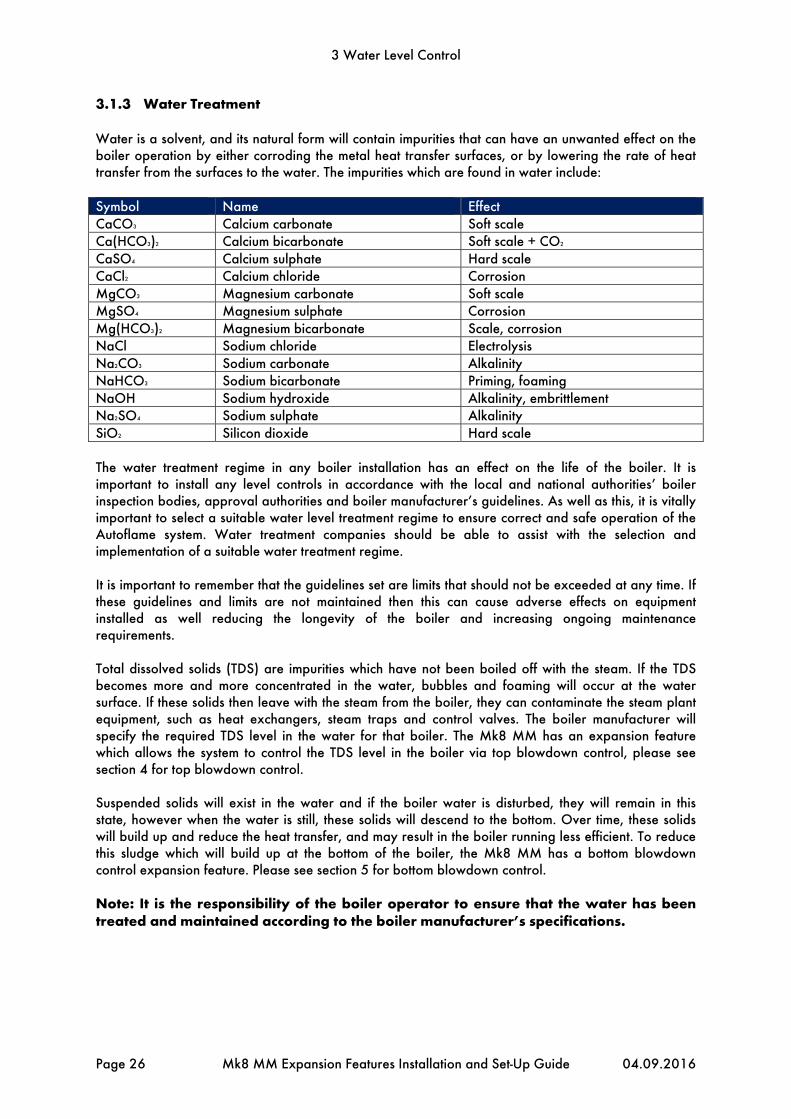
3.1.3 Water Treatment
Water is a solvent, and its natural form will contain impurities that can have an unwanted effect on the boiler operation by either corroding the metal heat transfer surfaces, or by lowering the rate of heat transfer from the surfaces to the water. The impurities which are found in water include: Symbol Name Effect CaCO3 Calcium carbonate Soft scale Ca(HCO3)2 Calcium bicarbonate Soft scale + CO2 CaSO4 Calcium sulphate Hard scale CaCl2 Calcium chloride Corrosion MgCO3 Magnesium carbonate Soft scale MgSO4 Magnesium sulphate Corrosion Mg(HCO3)2 Magnesium bicarbonate Scale, corrosion NaCl Sodium chloride Electrolysis Na2CO3 Sodium carbonate Alkalinity NaHCO3 Sodium bicarbonate Priming, foaming NaOH Sodium hydroxide Alkalinity, embrittlement Na2SO4 Sodium sulphate Alkalinity SiO2 Silicon dioxide Hard scale The water treatment regime in any boiler installation has an effect on the life of the boiler. It is important to install any level controls in accordance with the local and national authorities’ boiler inspection bodies, approval authorities and boiler manufacturer’s guidelines. As well as this, it is vitally important to select a suitable water level treatment regime to ensure correct and safe operation of the Autoflame system. Water treatment companies should be able to assist with the selection and implementation of a suitable water treatment regime. It is important to remember that the guidelines set are limits that should not be exceeded at any time. If these guidelines and limits are not maintained then this can cause adverse effects on equipment installed as well reducing the longevity of the boiler and increasing ongoing maintenance requirements. Total dissolved solids (TDS) are impurities which have not been boiled off with the steam. If the TDS becomes more and more concentrated in the water, bubbles and foaming will occur at the water surface. If these solids then leave with the steam from the boiler, they can contaminate the steam plant equipment, such as heat exchangers, steam traps and control valves. The boiler manufacturer will specify the required TDS level in the water for that boiler. The Mk8 MM has an expansion feature which allows the system to control the TDS level in the boiler via top blowdown control, please see section 4 for top blowdown control. Suspended solids will exist in the water and if the boiler water is disturbed, they will remain in this state, however when the water is still, these solids will descend to the bottom. Over time, these solids will build up and reduce the heat transfer, and may result in the boiler running less efficient. To reduce this sludge which will build up at the bottom of the boiler, the Mk8 MM has a bottom blowdown control expansion feature. Please see section 5 for bottom blowdown control. Note: It is the responsibility of the boiler operator to ensure that the water has been treated and maintained according to the boiler manufacturer’s specifications.

3 Water Level Control
04.09.2016 Mk8 MM Expansion Features Installation and Set-Up Guide Page 27
3.2 Water Valve
3.2.1 Specifications
Water valves are universal for feed water, TDS, and bottom blowdown function. ½” and ¾” water level valves must be used with large servomotors. Industrial unic 05 servomotors must be used 1” and 1 ½”, and industrial unic 10 for 2” water valves. for water valves bigger than ¾”.
Maximum operating pressure: 29 Bar (425 PSI)Maximum operating temperature: 235OC (455OF) Note: Autoflame water level probes are rated at a maximum 27 Bar (392 PSI) and 230OC (446OF).
Note: Please Valves and Servomotors manual for water level valve dimensions, drawings and information on service and maintenance.
Valve Type Size Part No. Servomotor
Large Unic 05 Unic 10
Threaded BSP/ NPT 15mm (½”) WLCVO15 • 20mm (¾”) WLCVO20 •
Flanged PN40 25mm (1”) WLCVO25/FL •
40mm (1 ½”) WLCVO40/FL • 50mm (2”) WLCVO50/FL •
Flanged ANSI 300lb 25mm (1”) WLCVO25/FLU •
40mm (1 ½”) WLCVO40/FLU • 50mm (2”) WLCVO50/FLU •

3 Water Level Control
Page 28 Mk8 MM Expansion Features Installation and Set-Up Guide 04.09.2016
3.2.2 Feed Water Valve Sizing
Obtain one value from the system relating to the units from the column headings, then compare with values using all tables and select the valve with the closest higher match, to size correctly. The feed water valves are available as threaded or flanged. The valves have a low pressure drop so when replacing an existing feed water valve, the valve size required may decrease by more than one.
Autoflame Part No. WLCV015 - ½” feed water valve water flow calculations @20°C Water Velocity Pressure Drop Across Valve Water Flow Rate Steam Flow Rate Ft/sec M/sec ∆P PSI ∆P Bar G/hr (imp) GPM (imp) US GPM lbs/hr Kg/hr
6 1.82 1 0.07 160 2.6 3.2 1600 727 9 2.74 2 0.14 235 3.9 4.7 2350 1068
15 4.57 5 0.34 380 6.3 7.6 3800 1727 21 6.40 10 0.68 560 9.3 11.2 5600 2545 26 7.90 15 1.03 700 11.6 14 7000 3182 32 9.73 20 1.38 820 13.6 16.4 8200 3727
Autoflame Part No. WLCV020 - ¾” feed water valve water flow calculations @20°C
Water Velocity Pressure Drop Across Valve Water Flow Rate Steam Flow Rate Ft/sec M/sec ∆P PSI ∆P Bar G/hr (imp) GPM (imp) US GPM lbs/hr Kg/hr
8 2.43 1 0.07 460 7.7 9.2 4600 2090 12 3.65 2 0.14 665 11 13.3 6650 3022 19 5.79 5 0.34 1100 18.3 22 11000 5000 28 8.53 10 0.68 1630 27.1 32.63 16300 7409 34 10.34 15 1.03 2000 33.3 40 20000 9090 40 12.16 20 1.38 2400 40 48 24000 10909
Autoflame Part No. WLCV025 - 1” feed water valve water flow calculations @20°C
Water Velocity Pressure Drop Across Valve Water Flow Rate Steam Flow Rate Ft/sec M/sec ∆P PSI ∆P Bar G/hr (imp) GPM (imp) US GPM lbs/hr Kg/hr
13 3.96 1 0.07 1560 26 31.2 15600 7091 21 6.4 2 0.14 2300 38.3 46 23003 1045632 9.75 5 0.34 3800 63.3 76 38005 1727546 14.02 10 0.68 5600 93.9 112 56007 2545860 18.24 15 1.03 7000 116.6 140 70008 3182270 21.28 20 1.38 8200 136.6 164 82011 37278
Autoflame Part No. WLCV040 – 1 ½” feed water valve water flow calculations @20°C
Water Velocity Pressure Drop Across Valve Water Flow Rate Steam Flow Rate Ft/sec M/sec ∆P PSI ∆P Bar G/hr (imp) GPM (imp) US GPM lbs/hr Kg/hr
17 5.17 1 0.07 4700 78.3 94 47005 21366 25 7.60 2 0.14 6700 11.6 134 67007 30458 39 11.86 5 0.34 11200 186.6 224 112015 50916 60 18.24 10 0.68 16500 275 330 165022 75010 75 22.80 15 1.03 20000 333.3 400 200028 90922 90 27.36 20 1.38 24000 400 480 240033 109126
Autoflame Part No. WLCV050 - 2” feed water valve water flow calculations @20°C
Water Velocity Pressure Drop Across Valve Water Flow Rate Steam Flow Rate Ft/sec M/sec ∆P PSI ∆P Bar G/hr (imp) GPM (imp) US GPM lbs/hr Kg/hr
21 6.38 1 0.07 10000 166.6 200 100014 45461 31 9.42 2 0.14 15000 250 300 150020 68191 46 13.99 5 0.34 24000 400 480 240033 10910672 21.89 10 0.68 36000 600 720 360049 16365985 25.84 15 1.03 44000 733 880 440061 200028
110 33.44 20 1.38 51000 850 1021 510072 231851

3 Water Level Control
04.09.2016 Mk8 MM Expansion Features Installation and Set-Up Guide Page 29
3.2.3 Feed Water Control
Traditional feed water control manages water level in the boiler, steam flow and feed water flow separately, whereas the Autoflame feed water control coordinates the water level, firing rate and steam pressure simultaneously. This 3-element feed water control has been granted a worldwide patent. The feed water going to the boiler can be controlled by either pump on/off only, pump on/off and servomotor, or pump on/off and VSD. The table below shows the terminals on the MM allocated for the feed water control parts. Terminal Description P- 0V supply to top blowdown and feed water servomotors P+ +12V supply to top blowdown and feed water servomotors TW Signal from feed water servomotor, indicating position I+ Current output, 4-20mA to feed water VSD V+ Voltage output, 0-10V to feed water VSD IV Common terminals for I+ and V+00 BFW Feed water pump contactor The table below shows the expansion options relating to feed water control. Expansion Option Description 2 Feed water control element 10 Pump turn off point 11 Pump turn off percentage 12 Pump turn on percentage 13 Feed water control proportional band 14 Feed water control integral time 15 Feed water control derivative time 16 Feed water servo open angle 20 Burner operation on feed water control fault The feed water pump can be set so that it turns off and on and at percentages above and below the control point/high water, via the feed water pump contactor on terminal BFW. If the feed water control is set with servomotor or VSD, then the 3-term PID control will operate. The proportional band set in expansion option 13 is the percentage between the control point and 1st low level where corrections are made to the servomotor/VSD to maintain the control point; outside of the p-band, the servomotor/VSD will remain fully open. The integral time set in expansion option 14 will set how fast the system responds to feed water changes; for a slower response increase time, and vice versa for a faster response. The derivative time set in expansion option 165 is used when a quick response is required but where overshoot is undesired; the water level should not rise too high above the control point, so the derivative element will need to be enabled. The feed water servomotor closed position is set by zeroing the potentiometer in Commissioning mode, however the open position is set in expansion option 16.

3 Water Level Control
Page 30 Mk8 MM Expansion Features Installation and Set-Up Guide 04.09.2016
3.3 Ways of Level Sensing
3.3.1 Overview
To activate water level control on the Mk8 MM, the Autoflame Water Level expansion software feature must be unlocked. The activation code for the serial number of the MM will need to be purchased using part number MK8001, and uploaded to the unit via Download Manager software. To activate analogue water level control on the Mk8 MM, both the Autoflame Water Level and Analogue Water Level expansion software features must be unlocked. The activation codes for the serial number of the MM will need to be purchased using part numbers MK8001 and MK8002, and uploaded to the unit via Download Manager software. Please see Autoflame PC Software Guide for more information on unlocking expansion features on the Mk8 MM using Download Manager software. Water level control requires a minimum of two level sensing devices, one of which must be an analogue device (capacitance probe or external level sensing device). The MM will show the capacitance probe reading(s), the external level sensor reading, and a combined reading of the optioned analogue sensing devices, as well as the 2nd low probe and auxiliary alarm inputs status.
Figure 3.3.1.i Water Level Status – Combined Level Sensing
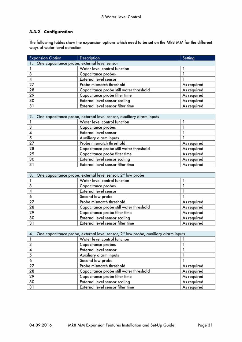
3 Water Level Control
04.09.2016 Mk8 MM Expansion Features Installation and Set-Up Guide Page 31
3.3.2 Configuration
The following tables show the expansion options which need to be set on the Mk8 MM for the different ways of water level detection. Expansion Option Description Setting 1. One capacitance probe, external level sensor 1 Water level control function 1 3 Capacitance probes 1 4 External level sensor 1 27 Probe mismatch threshold As required 28 Capacitance probe still water threshold As required 29 Capacitance probe filter time As required 30 External level sensor scaling As required 31 External level sensor filter time As required 2. One capacitance probe, external level sensor, auxiliary alarm inputs 1 Water level control function 1 3 Capacitance probes 1 4 External level sensor 1 5 Auxiliary alarm inputs 1 27 Probe mismatch threshold As required 28 Capacitance probe still water threshold As required 29 Capacitance probe filter time As required 30 External level sensor scaling As required 31 External level sensor filter time As required 3. One capacitance probe, external level sensor, 2nd low probe 1 Water level control function 1 3 Capacitance probes 1 4 External level sensor 1 6 Second low probe 1 27 Probe mismatch threshold As required 28 Capacitance probe still water threshold As required 29 Capacitance probe filter time As required 30 External level sensor scaling As required 31 External level sensor filter time As required 4. One capacitance probe, external level sensor, 2nd low probe, auxiliary alarm inputs 1 Water level control function 1 3 Capacitance probes 1 4 External level sensor 1 5 Auxiliary alarm inputs 1 6 Second low probe 1 27 Probe mismatch threshold As required 28 Capacitance probe still water threshold As required 29 Capacitance probe filter time As required 30 External level sensor scaling As required 31 External level sensor filter time As required

3 Water Level Control
Page 32 Mk8 MM Expansion Features Installation and Set-Up Guide 04.09.2016
5. One capacitance probe, 2nd low probe 1 Water level control function 1 3 Capacitance probes 1 6 Second low probe 1 27 Probe mismatch threshold As required 28 Capacitance probe still water threshold As required 29 Capacitance probe filter time As required 6. One capacitance probe, 2nd low probe, auxiliary alarm inputs 1 Water level control function 1 3 Capacitance probes 1 5 Auxiliary alarm inputs 1 6 Second low probe 1 27 Probe mismatch threshold As required 28 Capacitance probe still water threshold As required 29 Capacitance probe filter time As required 7. One capacitance probe, auxiliary alarm inputs 1 Water level control function 1 3 Capacitance probes 1 5 Auxiliary alarm inputs 1 27 Probe mismatch threshold As required 28 Capacitance probe still water threshold As required 29 Capacitance probe filter time As required 8. Two capacitance probes 1 Water level control function 1 3 Capacitance probes 2 27 Probe mismatch threshold As required 28 Capacitance probe still water threshold As required 29 Capacitance probe filter time As required 9. Two capacitance probes, auxiliary alarm inputs 1 Water level control function 1 3 Capacitance probes 2 5 Auxiliary alarm inputs 1 27 Probe mismatch threshold As required 28 Capacitance probe still water threshold As required 29 Capacitance probe filter time As required 10. Two capacitance probes, 2nd low probe 1 Water level control function 1 3 Capacitance probes 2 6 Second low probe 1 27 Probe mismatch threshold As required 28 Capacitance probe still water threshold As required 29 Capacitance probe filter time As required

3 Water Level Control
04.09.2016 Mk8 MM Expansion Features Installation and Set-Up Guide Page 33
11. Two capacitance probes, 2nd low probe, auxiliary alarm inputs 1 Water level control function 1 3 Capacitance probes 2 5 Auxiliary alarm inputs 1 6 Second low probe 1 27 Probe mismatch threshold As required 28 Capacitance probe still water threshold As required 29 Capacitance probe filter time As required 12. Two capacitance probes, external level sensor 1 Water level control function 1 3 Capacitance probes 2 4 External level sensor 1 27 Probe mismatch threshold As required 28 Capacitance probe still water threshold As required 29 Capacitance probe filter time As required 30 External level sensor scaling As required 31 External level sensor filter time As required 13. Two capacitance probes, external level sensor, auxiliary alarm inputs 1 Water level control function 1 3 Capacitance probes 2 4 External level sensor 1 5 Auxiliary alarm inputs 1 27 Probe mismatch threshold As required 28 Capacitance probe still water threshold As required 29 Capacitance probe filter time As required 30 External level sensor scaling As required 31 External level sensor filter time As required 14. Two capacitance probes, external level sensor, 2nd low probe 1 Water level control function 1 3 Capacitance probes 2 4 External level sensor 1 6 Second low probe 1 27 Probe mismatch threshold As required 28 Capacitance probe still water threshold As required 29 Capacitance probe filter time As required 30 External level sensor scaling As required 31 External level sensor filter time As required 15. Two capacitance probes, external level sensor, 2nd low probe, auxiliary alarm inputs 1 Water level control function 1 3 Capacitance probes 2 4 External level sensor 1 5 Auxiliary alarm inputs 1 6 Second low probe 1 27 Probe mismatch threshold As required 28 Capacitance probe still water threshold As required 29 Capacitance probe filter time As required 30 External level sensor scaling As required 31 External level sensor filter time As required

3 Water Level Control
Page 34 Mk8 MM Expansion Features Installation and Set-Up Guide 04.09.2016
16. External level sensor, auxiliary alarm inputs 1 Water level control function 1 4 External level sensor 1 5 Auxiliary alarm inputs 1 30 External level sensor scaling As required 31 External level sensor filter time As required 17. Auxiliary alarm inputs, 2nd low probe 1 Water level control function 1 5 Auxiliary alarm inputs 1 6 Second low probe 1 18. External level sensor, 2nd low probe 1 Water level control function 1 4 External level sensor 1 30 External level sensor scaling As required 31 External level sensor filter time As required Please see section 3.4 for more information on capacitance probes. Please see section 3.5 for more information on 2nd low safety probe. Please see section 3.6 for more information on external level sensor. Please see section 3.7 for more information on auxiliary alarm inputs.

3 Water Level Control
04.09.2016 Mk8 MM Expansion Features Installation and Set-Up Guide Page 35
3.4 Capacitance Probes
3.4.1 Overview
The Autoflame capacitance probes can be used in conjunction with the Mk8 MM to detect the water level in the boiler. The system safety is guaranteed as the level measurement is managed by two identical capacitance probes both of which measure and control to the level switching points entered at the time of commissioning. The capacitance probes are designed to work with steam boilers where the chemical treatment is maintained to the limits stated within these standards and guidelines. When the chemical treatment is maintained to levels under the maximum limits as stated in the standard’s tables, the water level probes will work as expected. When using two capacitance probes, the water level is read to a resolution of less than 1mm in still water. This resolution is maintained during normal operation by Autoflame’s patented “wave signature and turbulence management” software. The patented movement detection of water feature ensures that no static value can be accepted, i.e. the probes are in turbulent water. The swell management feature prevents intermittent shutdowns from the 1st low being switching due to increases in steam requirements. The Autoflame Micro-Modulation (M.M.) module knows the firing rate and boiler pressure, and accommodates for this transient condition by increasing the ‘control point’ level.
Figure 3.4.1.i Capacitance Probe
Movement Detection of Water When the burner is running it is expected that a wave turbulence signature of in excess of 20Hz / 1mm will always be present (due to vibration of thermal energy). Both probes are checked for this value. This feature ensures that either probe cannot read a still water condition when the burner is running. This safety check ensures no static or stuck value can be accepted, thereby checking that the probes are in water. Swell Management When there is a sudden drop in boiler pressure an increase in water level will be observed. This is due to the expansion of the steam bubbles in the water causing the water level to increase. It follows that the water feed would then turn off or go to a low flow condition. The Autoflame system identifies this ambiguous condition by monitoring the sudden increase in burner firing rate to meet the load demand and increases the “required water level” by up to 50% of the distance between normal “required level” and “high water level”. When normal conditions are reinstated and the boiler firing rate stabilises, the “required level” returns to the normal setting. This stops spurious shut downs due to 1st low being switched during these transient conditions. The Autoflame system knows what the firing rate and boiler pressure is at any one time and uses this information to identify the above condition. This feature is one of the main elements in the patent claim.
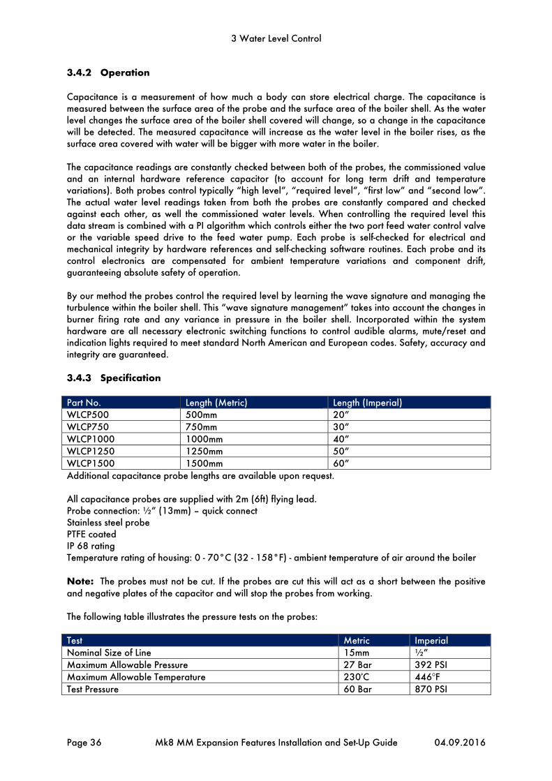
3 Water Level Control
Page 36 Mk8 MM Expansion Features Installation and Set-Up Guide 04.09.2016
3.4.2 Operation
Capacitance is a measurement of how much a body can store electrical charge. The capacitance is measured between the surface area of the probe and the surface area of the boiler shell. As the water level changes the surface area of the boiler shell covered will change, so a change in the capacitance will be detected. The measured capacitance will increase as the water level in the boiler rises, as the surface area covered with water will be bigger with more water in the boiler. The capacitance readings are constantly checked between both of the probes, the commissioned value and an internal hardware reference capacitor (to account for long term drift and temperature variations). Both probes control typically “high level”, “required level”, “first low” and “second low”. The actual water level readings taken from both the probes are constantly compared and checked against each other, as well the commissioned water levels. When controlling the required level this data stream is combined with a PI algorithm which controls either the two port feed water control valve or the variable speed drive to the feed water pump. Each probe is self-checked for electrical and mechanical integrity by hardware references and self-checking software routines. Each probe and its control electronics are compensated for ambient temperature variations and component drift, guaranteeing absolute safety of operation. By our method the probes control the required level by learning the wave signature and managing the turbulence within the boiler shell. This “wave signature management” takes into account the changes in burner firing rate and any variance in pressure in the boiler shell. Incorporated within the system hardware are all necessary electronic switching functions to control audible alarms, mute/reset and indication lights required to meet standard North American and European codes. Safety, accuracy and integrity are guaranteed. 3.4.3 Specification
Part No. Length (Metric) Length (Imperial) WLCP500 500mm 20” WLCP750 750mm 30” WLCP1000 1000mm 40” WLCP1250 1250mm 50” WLCP1500 1500mm 60” Additional capacitance probe lengths are available upon request. All capacitance probes are supplied with 2m (6ft) flying lead. Probe connection: ½” (13mm) – quick connect Stainless steel probe PTFE coated IP 68 rating Temperature rating of housing: 0 - 70°C (32 - 158°F) - ambient temperature of air around the boiler Note: The probes must not be cut. If the probes are cut this will act as a short between the positive and negative plates of the capacitor and will stop the probes from working. The following table illustrates the pressure tests on the probes: Test Metric Imperial Nominal Size of Line 15mm ½” Maximum Allowable Pressure 27 Bar 392 PSI Maximum Allowable Temperature 230PC 446OF Test Pressure 60 Bar 870 PSI

3 Water Level Control
04.09.2016 Mk8 MM Expansion Features Installation and Set-Up Guide Page 37
Figure 3.4.3.i Capacitance Probe – External View
Figure 3.4.3.ii Capacitance Probe – Internal View

234.4mm(9.23in)
42.5mm(1.67in)
9.0mm(0.35in)
24.4mm(0.96in)
15.2mm(0.60in)
12.0mm(0.47in)
3 Water Level Control
Page 38 Mk8 MM Expansion Features Installation and Set-Up Guide 04.09.2016
Dimensions

3 Water Level Control
04.09.2016 Mk8 MM Expansion Features Installation and Set-Up Guide Page 39
3.4.4 Installation Safety Guidelines
The notes and mechanical executions implicit in the following diagrams in sections 3.4.5 to 3.4.8 for capacitance probe installation should be used for guidance purposes only. Local, state and national codes must be adhered to in all cases. It is important to use only qualified and experience installation personnel who have been factory trained. Under all codes that Autoflame are aware of, it is not permitted install only two capacitance probes without an additional water level detection method. When the capacitance probes are installed on a boiler application in this way, the boiler must be protected with a separate auxiliary low water cut-off device.
**WARNING** ANY PERSON WORKING ON A BOILER MUST BE ADEQUATELY TRAINED AND
HAVE A THOROUGH APPRECIATION OF THE BOILER PLANT. IT IS THE RESPONSIBILITY OF THE FACTORY TRAINED TECHNICIAN TO ENSURE THAT THE
SYSTEM OPERATION MEETS LOCAL CODES AND REGULATIONS. For fire tube steam boilers, a sight gauge glass must be installed to visually indicate the level of the water in the boiler. The water in the sight gauge glass is cooler than the water the in the boiler, and does not contain bubbles or current effects. Note: When carrying out a boiler service, the capacitance probes must be cleaned and checked for correct and safe operation. Care must be taken to ensure that the PTFE coating on the surface of the probes is not damaged. After cleaning the probes, the water levels commissioned for those probes must be checked. The capacitance probes are used to commission the high, control point, 1st low, 2nd low and end of probe levels.

3 Water Level Control
Page 40 Mk8 MM Expansion Features Installation and Set-Up Guide 04.09.2016
3.4.5 Capacitance Probe – Externally Mounted Pots
Please see section 3.4.4 for installation safety guidelines.

HIGH WATER
REQUIRED LEVEL
1st LOW WATER
2nd LOW WATER
CONCENTRIC REDUCER
CONTINUOUS WELD
DRAIN VALVE
CONTINUOUS WELD BOILER SHELL
BOILER TUBES
CONTINUOUS WELD
1/2” BSP/NPT PARALLEL THREAD
INSTALLED WITH SUPPLIED
COPPER SEALING WASHER
CAPACITANCE PROBE
CONCENTRIC REDUCER
1m (3’0”) OF 10 mm (0.4”) PMA SUPPLIED
1.5m OF 4 CORE SCREEN PRE-WIRED INTO THE PROBE
CONTINUOUS WELD
DRAIN VALVE
CONTINUOUS WELD BOILER SHELL
BOILER TUBES
HIGH WATER
REQUIRED LEVEL
1st LOW WATER
2nd LOW WATER
HIGH WATER
REQUIRED LEVEL
1st LOW WATER
2nd LOW WATER
CONCENTRIC REDUCER POT DESIGN NOT
ALLOWING CLEANING PROCESS
CONTINUOUS WELD
CAPACITANCE PROBE
INSTALLED WITH SUPPLIED
COPPER SEALING WASHER
1/2” BSP/NPT PARALLEL THREADFLANGED FOR CLEANING ACCESS
1m (3’0”) OF 10mm (0.4”) PMA SUPPLIED
1.5m OF 4 CORE SCREEN PRE-WIRED INTO THE PROBE
SIG
HT/
GA
UG
E G
LAS
S C
AN
BE M
OU
NTE
D B
ETW
EEN
THES
E P
OIN
TS
SIG
HT/
GA
UG
E G
LAS
S C
AN
BE M
OU
NTE
D B
ETW
EEN
THES
E P
OIN
TS
FLANGED POT DESIGN ALLOWING
CLEANING PROCESS
3 Water Level Control
04.09.2016 Mk8 MM Expansion Features Installation and Set-Up Guide Page 41

HIGH WATER
REQUIRED LEVEL
1st LOW WATER
2nd LOW WATER
LEVEL PROBES INSTALLED DIRECTLY TO BOILER SHELL
NON-RETURN
VALVE
STEAM BOILER
SIGHT GLASS
AUTOFLAME FEED WATER VALVE CONTROLLED
BY A SERVOMOTOR (OPTIONAL V.S.D.)
FEED WATER PUMP
ISOLATION VALVE
AUTOFLAME FEED WATER
TEMP. SENSOR (PT1000)
OPTIONAL V.S.D. CONTROL
FOR FEED WATER PUMP
FLUE
SAFETY VALVECAPACITANCE
PROBES
STEAM NON-RETURN VALVE
STEAM FLOW VALVE/ CROWN VALVE
AUTOFLAME STEAM TEMP. SENSOR
3 Water Level Control
Page 42 Mk8 MM Expansion Features Installation and Set-Up Guide 04.09.2016
3.4.6 Capacitance Probe – Internally Mounted Pots
Please see section 3.4.4 for installation safety guidelines. If the probes are mounted directly into the boiler shell it is important to lag the flanges in order to avoid overheating of the electronics. It is recommended that they are not installed too close to the steam off-take and safety valve connection, but also not too close to the boiler end plates. If possible, they should be installed near the sight gauge glass.

I
HIGH WATER
REQUIRED LEVEL
1st LOW WATER
2nd LOW WATER
BOILER TUBES
2off 18mm x 120mm SLOTS
BOTTOM 1” OF THE PROBE IS THE
SEALING PLUG AND WILL NOT
GIVE A CAPACITANCE READING
RECOMMENDED MINIMUM 6” PIPE I.D.
10x 24mm HOLES EQUSPACED AROUND 6” PIPE
BOILER SHELL
1m (3’0”) OF 10mm (0.4”) PMA SUPPLIED
1.5m OF 4 CORE SCREEN PRE-WIRED INTO THE PROBE
CAPACITANCE PROBES
INSTALLED WITH COPPER
SEALING WASHER
1/2” BSP/NPT PARALLEL THREAD
RECOMMENDED
MINIMUM 6” PIPE TAPPING DETAIL
TAPPED 1/2” BSP
1/2
” C
LEA
RA
NC
E F
RO
M E
ND
OF
PR
OB
E S
HR
OU
D
1”
OF
CLE
AR
AN
CE
AB
OV
E B
OIL
ER
TU
BES
LEVEL PROBES MOUNTED DIRECTLY TO
BOILER SHELL (TOGETHER)
18mm WIDE SLOT BOTH SIDES
9mm WIDE SLOT BOTH SIDES
BOILER TUBES
2off 9mm x 67mm SLOTS
BOTTOM 1” OF THE PROBE IS THE
SEALING PLUG AND WILL NOT GIVE
A CAPACITANCE READING
RECOMMENDED MINIMUM 3” PIPE I.D.
10 x 12mm HOLES EQUISPACED AROUND 3” PIPE
BOILER SHELL
1m (3’0”) OF 10mm (0.4”) PMA SUPPLIED
1.5m OF 4 CORE SCREEN PRE-WIRED INTO THE PROBE
CAPACITANCE PROBE
INSTALLED WITH SUPPLIED
COPPER SEALING WASHER
1/2” BSP/NPT PARALLEL THREAD
1/2
” C
LEA
RA
NC
E F
RO
M E
ND
OF
PR
OB
E S
HR
OU
D
1”
OF
CLE
AR
AN
CE
AB
OV
E B
OIL
ER
TU
BE
S
3 Water Level Control
04.09.2016 Mk8 MM Expansion Features Installation and Set-Up Guide Page 43

3 Water Level Control
Page 44 Mk8 MM Expansion Features Installation and Set-Up Guide 04.09.2016
3.4.7 Capacitance Probe – Installation for a Water Tube Boiler
Please see section 3.4.4 for installation safety guidelines.

3 Water Level Control
04.09.2016 Mk8 MM Expansion Features Installation and Set-Up Guide Page 45
3.4.8 External Probe Chamber Dimensions
Please see section 3.4.4 for installation safety guidelines.

3 Water Level Control
Page 46 Mk8 MM Expansion Features Installation and Set-Up Guide 04.09.2016
3.4.9 Configuration
The table below shows the terminals allocated on the MM for the capacitance probes. Terminal Description 1P+ +9V supply to capacitance probe 1 1P- 0V supply to capacitance probe 1 1T+ Digital communications connections from capacitance probe 1 1T- Digital communications connections from capacitance probe 1 2P+ +9V supply to capacitance probe 2 2P- 0V supply to capacitance probe 2 2T+ Digital communications connections from capacitance probe 2 2T- Digital communications connections from capacitance probe 2 When wiring the capacitance probes, the screen is connected through the casing of the lead and through the probe; therefore the flying lead should be connected to the MM without a screen. The screen should be carried through until the connection to the MM; the screen should not be connected to the S terminal. The table below shows the expansion options to be set when using the capacitance probes with the MM for water level detection. Expansion Option Description Setting 1 Water level control function 1 3 Capacitance probes 1 or 2 27 Probe mismatch threshold As required 28 Capacitance probe still water threshold As required 29 Capacitance probe filter time As required

3 Water Level Control
04.09.2016 Mk8 MM Expansion Features Installation and Set-Up Guide Page 47
3.5 2nd Low Probe
3.5.1 Overview
The 2nd low probe is a conductivity probe, and its purpose it to act as an additional 2nd low water cut-off when the water falls too low in the boiler. The conductive technology with safe electronic control has been granted a worldwide patent for its continuous electrical and mechanical self-checking software. If the water level in the boiler falls below probe, then the 2nd low water level alarm will occur. The water level may be low due to insufficient water in the feed water tank, feed water pump failure, feed water line isolated and/or the level controls have failed. If there is not enough water in the boiler, the heated tubes will be left exposed and unable to cool down as there is no longer water to transfer the heat to. If the burner were to continue firing, the temperature of the tubes would be rapidly increase, reducing the metal strength, and could cause a collapse or explosion. On the MM system, the 2nd low water level alarm will shut down the burner. The probe can be cut to length to suit the application.
Figure 3.5.1.i 2nd Low Probe

3 Water Level Control
Page 48 Mk8 MM Expansion Features Installation and Set-Up Guide 04.09.2016
3.5.2 Operation
The water level detection probes use capacitance technology, whereas the 2nd low safety probe uses conductive technology. Following basic electric circuit theory, when the probe is in the water in the boiler and an electrical voltage is applied, the current will flow; when water level drops below the probe, no current will flow. This is the basic principle of the 2nd low safety probe, if the water levels drop below the cut-length of the probe, then a 2nd low water alarm will occur on the MM or for standalone mode, the volt-free connection will open to indicate this alarm. When used with an MM, the 2nd low water alarm requires a manual reset.
3.5.3 Specifications
The specifications of the 2nd low probe include: Part number SLP70001 Compatible with Mk7 MM and Mk8 MM Can be used with Autoflame system or as a standalone unit Probe can be cut to length to suit application Internal relay self-checking Conductive technology completely different to capacitance probes Stainless steel and PTFE construction Supplied with 2m (6ft) flying lead Quick connect multi-pin flying lead Volt free contacts for external safety devices or circuits Offsite status logging via Mk7 DTI and direct Modbus from Mk8 MM Tested and approved to UL standard
2nd Low Probe Flying Lead The 2nd low probe is supplied with a 2m (6ft) flying lead, which has quick connect multi-pin end. The cable shield is connected to the probe body. Pin Description Wire MM Terminal 1 Optional ground connection (not used) 2 0V Power (DC or AC) Blue 4P- 3 12V Power (DC or AC) Red 4P+ 4 RS485 Comms - Yellow 5T- 5 RS485 Comms + Green 5T+ 6 Volt-free connection 1 (250mA max) Brown 7 Volt-free connection 2 (250mA max) Purple If using the 2nd low probe for standalone operation, then the volt-free connections must be used; the volt-free connection will be closed when water is detected and there is no system fault.

42.2mm
(1.66in)
12.0mm(0.47in)
307.0mm(12.10in)
3 Water Level Control
04.09.2016 Mk8 MM Expansion Features Installation and Set-Up Guide Page 49
Dimensions

3 Water Level Control
Page 50 Mk8 MM Expansion Features Installation and Set-Up Guide 04.09.2016
3.5.4 Installation and Safety Guidelines
The probe must be cut to according to the water in the boiler; this length should match the commissioned 2nd low level of the capacitance probes or external level sensing device. The 2nd low probe should not be installed in the same pot as the water level probes. Any blockages in the line will affect the levels; therefore the 2nd low probe should be fitted in a pot with a separate line to the water level probes line. If the water level probes are installed in a pot externally mounted to the boiler as shown in section 3.4.5, the 2nd low probe can either be fitted in a separate pot, or internally mounted pot directly into the boiler. If the water level probes are installed in internally mounted pots as shown in section 3.4.6, the 2nd low probe can also in an internally mounted pot directly into the boiler.
Figure 3.5.4.i MM Display 2nd Low Probe
**WARNING** ANY PERSON WORKING ON A BOILER MUST BE ADEQUATELY TRAINED AND
HAVE A THOROUGH APPRECIATION OF THE BOILER PLANT. IT IS THE RESPONSIBILITY OF THE FACTORY TRAINED TECHNICIAN TO ENSURE THAT THE
SYSTEM OPERATION MEETS LOCAL CODES AND REGULATIONS.

3 Water Level Control
04.09.2016 Mk8 MM Expansion Features Installation and Set-Up Guide Page 51
3.5.5 Configuration
The table below shows the terminals allocated on the MM for the 2nd low safety probe. Terminal Description 5T+ Digital communication connections from 2nd low resistance probe 5T- Digital communication connections from 2nd low resistance probe 4P+ +12V supply to 2nd low resistance probe 4P- 0V supply to 2nd low resistance probe The screen is connected through the casing of the flying lead supplied with the 2nd low safety probe. When connecting the flying lead to the MM, do not wire a screen at the MM. The table below shows the expansion options to be set when using the 2nd low probe with the MM. Expansion Option Description Setting 1 Water level control function 1 6 Second Low Probe 1 Note: 2nd low probe can only be used in conjunction with an analogue sensing device such as two capacitance probes or one capacitance and an external level sensor at minimum; please see section 3.3 Ways of Level Sensing for more information.
Figure 3.5.5.i 2nd Low Probe Installation Example
To install the 2nd low probe, no commissioning is required; just simply the probe in expansion option 6. The bottom of the 2nd low probe should be at the capacitance probes/external level sensor commissioned 2nd low level or higher.

3 Water Level Control
Page 52 Mk8 MM Expansion Features Installation and Set-Up Guide 04.09.2016
3.6 External Level Sensor
An external level sensor can be used with one or two capacitance probes for water level detection on the Mk8 MM. This sensor will give an analogue signal to the MM to indicate level across a 4-20mA input range. The water levels commissioned for the external level sensor are the same for the capacitance probes which are HIGH, CONTROL POINT, 1st LOW, 2nd LOW and END OF PROBE. The table below shows the terminals allocated on the MM for an external level sensor. Terminal Description EX- Common for terminal EX+ EX+ Current input, 4-20mA for external water level probe (or fuel flow feedback) Note: The external level sensor cannot be used with 4-20mA input for the fuel flow feedback, see option 57. The table below shows the expansion options to be set to for using external level sensor on the MM. Expansion Option Description Setting 1 Water level control function 1 4 External level sensor 1 30 External level sensor scaling As required 31 External level sensor filter time As required Note: External level sensor can only be used in conjunction with one capacitance probe at minimum; please see section 3.3 Ways of Level Sensing for more information.

3 Water Level Control
04.09.2016 Mk8 MM Expansion Features Installation and Set-Up Guide Page 53
3.7 Auxiliary Alarm Inputs
For additional safety, it is possible to retain the site’s existing float type level controls by using auxiliary alarm inputs. The schematic below shows a guide of how to wire these alarm inputs.
Figure 3.7.i Wiring Auxiliary Alarm Inputs Note: If any of the three alarms are not being used when auxiliary alarm inputs have been enabled, a line voltage input should be connected to the corresponding terminals to stop a fault occurring. The table below shows the expansion options to be set on the MM for the auxiliary alarm inputs. Expansion Option Description Setting 1 Water level control function 1 5 Auxiliary alarm inputs 1 Note: Auxiliary alarm inputs can only be used in conjunction with an analogue sensing device such as two capacitance probes or one capacitance and an external level sensor at minimum; please see section 3.3 Ways of Level Sensing for more information.

3 Water Level Control
Page 54 Mk8 MM Expansion Features Installation and Set-Up Guide 04.09.2016
3.8 Commissioning Procedure
3.8.1 Commissioning Checks
When commissioning a burner with Autoflame water level cotnrol, the water level probes and external water level sensor must be commissioned initially before the combustion curve is put in. Once the burner is commissioned with the Mk8 MM, the water level probes will need to be recommissioned once the boiler is up to pressure, and water in the boiler is hot enough.
**WARNING** ANY PERSON WORKING ON A BOILER MUST BE ADEQUATELY TRAINED AND
HAVE A THOROUGH APPRECIATION OF THE BOILER PLANT. IT IS THE RESPONSIBILITY OF THE FACTORY TRAINED TECHNICIAN TO ENSURE THAT THE
SYSTEM OPERATION MEETS LOCAL CODES AND REGULATIONS. When all the installation and burner adjustments are completed, the entire burner control system should be tested in accordance with the manufacturer’s instructions. The procedure should verify the correct operation of:
1. Each operating control (temperature, pressure etc.) 2. Each limit switch (temperature, pressure, low water cut-off, etc.) 3. Each interlock switch (airflow switch, high and low fuel pressure or temperature switches,
purge and low fire switches, fuel valve proof of closure interlock etc.) 4. Pilot flame failure response and lockout. 5. Main flame failure response and lockout. 6. Tight shut-off for all valves.
Please refer to section 3.4.4 for the Installation and Safety Guidelines. 3.8.2 Levels
End of Probe: The end of probe level is used to identify the point below which the probe cannot obtain a valid water level, it has no operational use. High: A high water level, although not dangerous is undesirable as water may infiltrate the steam header. If the boiler water level goes above this point the burner may or may not continue to run depending on the system configuration. If a high water level condition is detected high water audible and visual indicators are activated to notify the user. The audible indicator may be muted by means of the mute/reset push button. The burner can be set continue or stop firing at high water in expansion option 9. Control Point: This is the ideal water level the feed water control will try to maintain. 1st Low: A 1st low water level is a point below the control point at which the burner will turn off. If the water level falls below this point 1st low audible and visual indicators are activated. The audible indicator may be muted by means of the mute/reset push button. If the water level is restored above this point the burner will start automatically and all indicators will also be reset. 2nd Low: A 2nd low water level is a point below 1st low at which the burner will remain off. If the water level falls below this point 2nd low audible and visual indicators are activated. The audible indicator may be muted by means of the mute/reset push button. Even if the water level is restored above this point the burner will remain off. Operator intervention is required to manually reset the system and can only be performed once the level is above the 2nd low point. The 2nd low reset condition is non-volatile - if the system is powered down the reset condition will remain when power is reapplied. In this scenario the operator reset will still be necessary.

3 Water Level Control
04.09.2016 Mk8 MM Expansion Features Installation and Set-Up Guide Page 55
3.8.3 Setting End of Probe Level
Figure 3.8.3.i Commission End of Probe Level
Power on the MM and in Commission mode, press to begin the water level commission process. When commissioning the capacitance probes the readings will display in Hz. The external level sensor will display in mA.
Press to begin commissioning. The first position to be entered is the end of probe level. This is the minimum level of water in the boiler, and this is displayed as the lowest water visible in the sight gauge glass. Increase the water level until the it reaches the end of the capacitance probe/
external level sensor. Press to turn the pump on. Press to open the
servomotor/ increase or decrease the VSD output in enabled in expansion option 2. Press to turn the pump off. As the water level exceeds the end of the probe, the displayed probe values will begin to change.
To leave the water level commissioning process, press .

3 Water Level Control
Page 56 Mk8 MM Expansion Features Installation and Set-Up Guide 04.09.2016
Figure 3.8.3.ii Store of End of Probe Level
Close the feedwater valve and turn the pump off once the desired level is reached for the end of
probe. Allow some time for the readings to settle and then press to store these readings. Once the level has been entered, it is possible to update the commissioned readings by adjusting the
water level and pressing .

3 Water Level Control
04.09.2016 Mk8 MM Expansion Features Installation and Set-Up Guide Page 57
3.8.4 Setting 2nd Low Level
Figure 3.8.4.i Commission 2nd Low Level
After storing or updating the end of probe level, press to increase the water level to the 2nd low level. It is recommended that there is a 25mm (1”) gap between the commissioned levels, which is approximately 500Hz. Once the water has risen to the required 2nd low level, turn the pump off and close the valve. Let the
readings settle and press . If required, the 2nd low level can be updated by then adjusting
the water level and pressing once the position has been stored.

3 Water Level Control
Page 58 Mk8 MM Expansion Features Installation and Set-Up Guide 04.09.2016
3.8.5 Setting 1st Low Level
Figure 3.8.5.i Commission 1st Low Level
After storing or updating the 2nd low level, press to increase the water level to the 1st low level. Once the water has risen to the required 1st low level, turn the pump off and close the valve. Let the
readings settle and press . If required, the 1st low level can be updated by then adjusting
the water level and pressing once the position has been stored.

3 Water Level Control
04.09.2016 Mk8 MM Expansion Features Installation and Set-Up Guide Page 59
3.8.6 Setting Control Point Level
Figure 3.6.8.i Commission Control Point Level
After storing or updating the 1st low level, press to increase the water level to the 1st low level. Once the water has risen to the required control point level, turn the pump off and close the valve. Let
the readings settle and press . If required, the control point level can be updated by then
adjusting the water level and pressing once the position has been stored.

3 Water Level Control
Page 60 Mk8 MM Expansion Features Installation and Set-Up Guide 04.09.2016
3.8.7 Setting HIGH Level
Figure 3.8.7.i Store High Water Level
After storing or updating the control point level, press to increase the water level to the high water level. Once the water has risen to the required high water level, turn the pump off and close the valve. Let the
readings settle and press . If required, the high water level can be updated by then
adjusting the water level and pressing once the position has been stored.

3 Water Level Control
04.09.2016 Mk8 MM Expansion Features Installation and Set-Up Guide Page 61
3.8.8 Save Commissioning
Figure 3.8.8.i Save Commissioning
After storing or updating the high water level, press to save the commissioned water level readings.

3 Water Level Control
Page 62 Mk8 MM Expansion Features Installation and Set-Up Guide 04.09.2016
Figure 3.8.8.ii Fuel/Air Commission
Once the water level has been commissioned, adjust the water level to fall to control point, and either
press to commission the burner after the operational checks of the water level operation
has been carried out in section 3.8.9, or press to return to Commissioning Mode.

3 Water Level Control
04.09.2016 Mk8 MM Expansion Features Installation and Set-Up Guide Page 63
3.8.9 Operational Checks
Once the capacitance probes/external level sensor have been commissioned, the water level operation must be checked for safety and alarms, then the burner can be commissioned and the probes re-commissioned when there is heat in the boiler. All local & national codes for safe operation of boiler plant must be respected. If in any doubt contact your local specialist authority. Water level operation must be checked after commissioning or subsequent to modification of any setups. These operational checks are for boilers without a shunt switch, see section 3.9.3 for shunt switch. Set the system to RUN mode and allow the burner to fire. With the boiler supplying steam at a steady rate check that the water level is maintained at the control point for modulating control. For on/off control, check that the boiler feed water pump turns on and off appropriately at the commissioned points. Ensure that all audible and visual alarm indicators are inactive. Reduce the level of the water (by blow down or other suitable means). Check that a 1st low alarm occurs and the burner stops firing when the water level is just below the commissioned 1st low level. Ensure that the 1st low audible and visual indicators are active. If fitted, press the external mute/reset button and check that the audible alarm is muted. Reduce the level of the water further and check that the 2nd low alarm is displayed when the water level is just below the commissioned 2nd low level; the burner will remain off. Ensure that the 2nd low audible and visual indicators are active. If fitted, press the external mute/reset button and check that the audible alarm is muted. All 1st Low/2nd low alarm conditions must be cleared before proceeding to test the high water. To test high water it will be necessary to increase the water level to just above that of the commissioned high water position. If there is no means to manually increase the level of the water it is possible to select Water Level Commission mode and increase the level of the water manually. The unit can then be restarted by de-selecting and re-selecting the fuel. The unit will restart in RUN mode and should report a high water alarm. Check the burner operation runs or stops according to expansion option 9. Ensure that the high water audible and visual indicators are active. If fitted, press the external mute/reset button to check that the audible alarm is muted. Check the operation of the TB output terminal if using a contactor with solenoid valve. Once the water level control has passed these operational checks, the burner can now be commissioned with a fuel to air curve, after which the probes are re-commissioned at boiler pressure.

3 Water Level Control
Page 64 Mk8 MM Expansion Features Installation and Set-Up Guide 04.09.2016
3.8.10 Adjust Control Point
Figure 3.8.10.i Adjust Control Point
The control point which is set during water level commissioning can be adjusted through Online
Changes. Press in Online Changes and then go to the Water Level Status and change the control point as required. This cannot be set higher than the high water level or lower than 1st low level. The pump on/off percentages and pre-level alarms will change with the new control point.
Once the control point has been adjusted, press to save, and then press to leave the Water Level Status screen.

3 Water Level Control
04.09.2016 Mk8 MM Expansion Features Installation and Set-Up Guide Page 65
3.9 Water Level Control Functions
This section describes the additional functions used to accurately control the water level. 3.9.1 Pre-Alarms
In addition to the water level alarms for high water, 1st low and 2nd low, pre-alarms can also be set which include pre-high and pre-1st low. The table below shows the expansion options for pre-alarms. Expansion Option Description 7 Pre-high alarm percentage 8 Pre-first-low alarm percentage The pre-high level is set as a percentage between the control point and high water level, with the control point representing 0% and the high water level representing 100%. If the water exceeds this pre-high level, a warning will occur and the burner will continue to fire. The pre-1st low level is set as a percentage between the control point and 1st low level, with the control point representing 0% and the 1st low level representing 100%. If the water falls below this pre-1st low level, a warning will occur and the burner will continue to fire. 3.9.2 Pump Bypass
The pump bypass operation is prevents the pump pushing water against a closed feed water valve. The terminal used is TB pump bypass contactor. The table below shows the expansion options for pump bypass. Expansion Option Description 17 Pump bypass operation 18 Pump bypass switch point 19 Pump bypass hysteresis The pump can be bypassed at a percentage set in expansion option 18, above or below the switch point. The switch point is set as percentage of the feed water valve open position set in expansion option 16. For pump bypass on above switch point, the pump bypass will turn on at a percentage above the valve open range set as a switch point, and it will turn off at a percentage below the switch point set as the hysteresis from the switch point. For pump bypass on below switch point, the pump bypass will turn on at a percentage below the valve open range set as a switch point, and it will turn off at percentage above the switch point, set as the hysteresis from the switch point.

3 Water Level Control
Page 66 Mk8 MM Expansion Features Installation and Set-Up Guide 04.09.2016
3.9.3 Test Outputs and Shunt Switch
The test input terminal TST can be used to check the auxiliary alarm outputs or the shunt switch operation when the burner is firing. The table below shows the expansion options for the test input. Expansion Option Description 21 Function of test input 22 Shunt switch – time to 1st low 23 Shunt switch – time to 2nd low When the test input is set for auxiliary alarm outputs checks, hold the test input continuously to cycle through the alarm outputs every two seconds. For shunt switch test, there is time delay for the burner to reach 1st low set in expansion option 22, allowing the operator to decrease the water level to check the 1st low alarm. If the water does not drop to 1st low within this time, the shunt switch test is cancel and the MM reverts to normal operation. There is additional delay set in expansion option 23 to allow the operator to decrease the water to 2nd low to check the 2nd low alarm. If the water level does not drop in this time, the MM leave shunt switch mode and the burner will turn off. The timer will display for when doing these tests, as shown below. After reaching 2nd low, if the water level does not rise to control point within 10 minutes, alarms will occur. The alarm outputs and shunt switch can also be checked via the Water Level Status screen on the MM.
Figure 3.9.3.i Trigger Shunt Switch
Press to cycle the alarm outputs every 2 seconds, and press to check the water level alarms as described above.
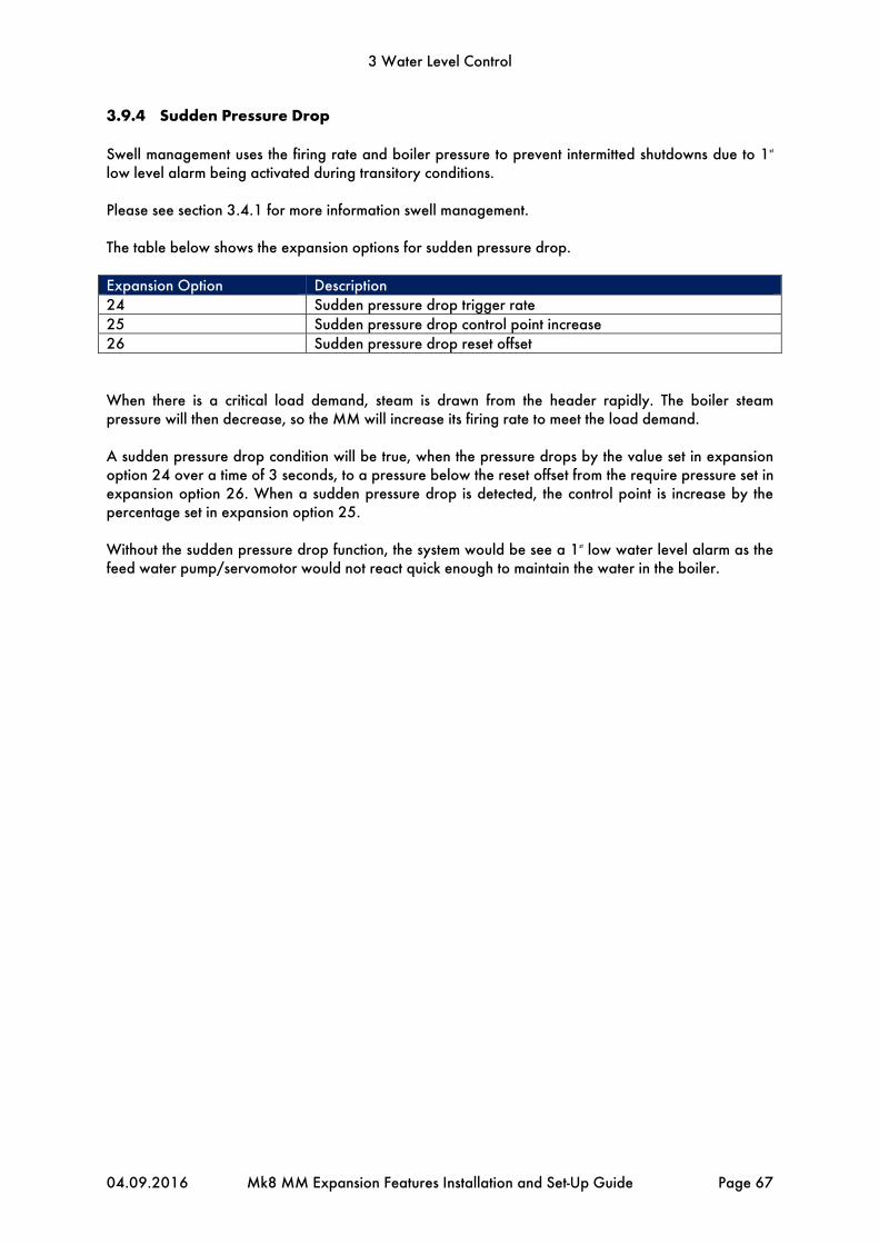
3 Water Level Control
04.09.2016 Mk8 MM Expansion Features Installation and Set-Up Guide Page 67
3.9.4 Sudden Pressure Drop
Swell management uses the firing rate and boiler pressure to prevent intermitted shutdowns due to 1st low level alarm being activated during transitory conditions. Please see section 3.4.1 for more information swell management. The table below shows the expansion options for sudden pressure drop. Expansion Option Description 24 Sudden pressure drop trigger rate 25 Sudden pressure drop control point increase 26 Sudden pressure drop reset offset When there is a critical load demand, steam is drawn from the header rapidly. The boiler steam pressure will then decrease, so the MM will increase its firing rate to meet the load demand. A sudden pressure drop condition will be true, when the pressure drops by the value set in expansion option 24 over a time of 3 seconds, to a pressure below the reset offset from the require pressure set in expansion option 26. When a sudden pressure drop is detected, the control point is increase by the percentage set in expansion option 25. Without the sudden pressure drop function, the system would be see a 1st low water level alarm as the feed water pump/servomotor would not react quick enough to maintain the water in the boiler.

3 Water Level Control
Page 68 Mk8 MM Expansion Features Installation and Set-Up Guide 04.09.2016
3.10 Faults
The table below show the faults which are directly related to the water level control function. For the full list of faults including errors, lockouts, alarms, warnings, setting conflicts and forced commission reasons, please see section 4 in the Mk8 MM Installation and Commissioning Guide. Fault Message Description Type 100 Cap Probe 1 Communications
Fault No comms with capacitance probe 1 Alarm
Check wiring and screen on terminals 1P+, 1P-, 1T+ and 1T- Check capacitance probe 1
101 Cap Probe 2 Communications Fault
No comms with capacitance probe 2 Alarm
Check wiring and screen on terminals 2P+, 2P-, 2T+ and 2T- Check capacitance probe 2
102 Cap Probe 1 Short Circuit Hz reading is below 10kHz Alarm
Check water level Hz reading Check wiring on terminals 1P+, 1P-, 1T+ and 1T-
103 Cap Probe 2 Short Circuit Hz reading is below 10kHz Alarm
Check water level Hz reading Check wiring on terminals 2P+, 2P-, 2T+ and 2T-
104 Cap Probe 1 Temp Compensation Error
Temperature corrected probe reference is not as expected
Alarm
Re-commission capacitance probes
105 Cap Probe 2 Temp Compensation Error
Temperature corrected probe reference is not as expected
Alarm
Re-commission capacitance probes
106 Cap Probe 1 Still Water Detected
Wave signature high to low peak distance is less than still water threshold
Alarm
Check still water threshold in expansion option 28 Check capacitance probe 1 reading history
107 Cap Probe 2 Still Water Detected
Wave signature high to low peak distance is less than still water threshold
Alarm
Check still water threshold in expansion option 28 Check capacitance probe 2 reading history
108 Cap Probe 1 Serial Number Mismatch
Probe serial number detected is not the commissioned probe serial number
Alarm
If changing capacitance probe 1, re-commission is required
109 Cap Probe 2 Serial Number Mismatch
Probe serial number detected is not the commissioned probe serial number
Alarm
If changing capacitance probe 2, re-commission is required
110 Cap Probe 1 Detected But Not Optioned
Probe connected but not optioned Alarm
Check expansion options 1 and 3 Check wiring on terminals 1P+, 1P-, 1T+ and 1T- Probe may require commissioning
111 Cap Probe 2 Detected But Not Optioned
Probe connected but not optioned Alarm
Check expansion options 1 and 3 Check wiring on terminals 2P+, 2P-, 2T+ and 2T- Probe may require commissioning

3 Water Level Control
04.09.2016 Mk8 MM Expansion Features Installation and Set-Up Guide Page 69
Fault Message Description Type 112 External Level Sensor Input
Low 3mA or lower received from 4-20mA external level sensor
Alarm
Check feedback from external level sensor Check wiring on terminals EX- and EX+
113 Probe Reading Mismatch Difference between probes/sensor readings is below mismatch threshold
Alarm
Check expansion option 27 Check capacitance probes and sensor readings
114 Probe Serial Numbers are the Same
One capacitance probe detected on both capacitance probe terminals
Alarm
If using two capacitance probes, then two individual probes must be connected Check wiring on terminals 1P+, 1P-, 1T+, 1T-, 2P+, 2P-, 2T+ and 2T-
120 Aux WL Inputs Mismatch High water and 1st or 2nd low auxiliary level inputs detected simultaneously
Alarm
Check wiring on terminals HAI, 1AI and 2AI
121 Water Levels Diverse Probes/ sensor detects 1st or 2nd low and high water simultaneously
Alarm
Check water level readings for probes and sensor if optioned Re-commission probes with/without sensor
122 Permanent Alarm Reset Input Input held on alarm reset terminal for more than 10 seconds
Alarm
Check input on terminal M/R
123 Second Low Probe Communications Fault
No comms with second low probe Alarm
Check wiring and screen on terminals 5T+, 5T-, 4P- and 4P+ Check second low probe
124 Second Low Probe Hardware Fault
Internal check failed Alarm
Contact Autoflame
125 Permanent Test Input Input held on test terminal for more than 60 seconds
Alarm
Check input on terminal TST
126 Second Low Probe Detected But Not Optioned
Second low probe connected but not optioned
Alarm
Check expansion option 6 Check wiring on terminals 5T+, 5T-, 4P- and 4P+ Probe may require commissioning
127 Aux WL Inputs Detect But Not Optioned
Mains detected on auxiliary WL inputs but not optioned
Alarm
Check expansion option 5 Check wiring on terminals HAI, 1AI and 2AI
130 Feed Water Servo Position Error
Servomotor is outside of the commissioned range
Alarm/Warning – exp. option 20
Check wiring on terminals P-, FW and P+ Check signal cable form the MM to the servomotor is screened at one end Check that the servomotor is zeroed correctly Alarm if expansion option 20 is set

3 Water Level Control
Page 70 Mk8 MM Expansion Features Installation and Set-Up Guide 04.09.2016
Fault Message Description Type 131 Feed Water Servo Movement
Error Servomotor moves when not expected and vice versa
Alarm/Warning – exp. option 20
Check wiring and voltages on terminals P-, FW, P+ and MVI, MVD Check servomotor drives in correct direction Check feed water valve is not stuck Alarm if expansion option 20 is set to 1
150 High Water Probes/sensor detect water level above commissioned high water
Alarm/Warning – exp. option 9
Check water level reading Alarm if expansion option 9 is set to 1
151 Pre-High Water Probes/sensor detect water level above set pre-high water
Warning
Check water level reading Check expansion option 7
152 Pre-1st Low Probes/sensor detect water level below set pre-1st low
Warning
Check water level reading Check expansion option 8
153 1st Low Probes/sensor detect water level below commissioned 1st low
Alarm
Check water level reading 1st low alarm will automatically clear if water level increases above 1st low
154 2nd Low Probes/sensor detect water level below 2nd low
Alarm
Check water level reading 2nd low alarm requires manual reset
155 Shunt Switch Time Expired Once shunt switch time expires, system goes to normally running
Warning
If water drops after shunt switch time expires, system will generates 1st or 2nd low as relevant

4 Top Blowdown
04.09.2016 Mk8 MM Expansion Features Installation and Set-Up Guide Page 71
4 TOP BLOWDOWN
4.1 Overview
4.1.1 Importance of Maintaining TDS
To manage a steam boiler for optimum efficiency and reliability an important requirement is to ensure that the total dissolved solids (TDS) in the water are measured and controlled to the right level for that boiler. It is generally accepted that for water tube boilers the level of TDS measured should not exceed 1,500 PPM by volume and for smoke tube boilers the TDS should not be higher than 2,500 PPM by volume. The figures stated are not definitive and in all applications the recommendations of the boiler manufacturer or water treatment chemist should be implemented. It has been established that the conductivity of water is proportional to the measured TDS as long as the temperature remains constant. Any variations in temperature will affect the measured conductivity by nominally 2% per 1°C. It follows that the temperature of the water must be measured and the conductivity reading must be adjusted before a TDS reading can be extrapolated from this line of data. The Autoflame system incorporates a temperature measurement sensor in the steam drum to establish the steam temperature. This data stream is used to constantly correct the conductivity value. A second variable that effects the conductivity measurement is polarization of the water sample. This occurs when electrical energy from the probe builds up a relatively tiny offset above or below the earth (0 volt value). This polarization value is typically noticeable when a continuous frequency is being emitted from the probe as part of the conductivity measurement method. The Autoflame system deals with the potential problem of polarization in the following manner. The probe measures any build-up of voltage potential above or below earth or 0V in the water sample. The measured polarization voltage data is used to modify the conductivity calculation. The Autoflame system emits electrical energy at a rate of 10x 300 microsecond pulses every second. This translates into a method where we are emitting electrical energy for 0.6% of the sample time. All other manufacturers who use the frequency method are emitting electrical energy for 100% of the sample time. It follows that the polarization problem in these cases would be 167 times greater. A third problem that affects the accuracy of the TDS measurement is the build up of scale on the probe electrode. By design the water sampling container has been arranged so that the turbulence created during the blow down sequence will ensure that the probe remains effectively free of scale or deposited solids that could be held in suspension. The probe is self-cleaning. The sampling container has a known orifice size. From this it is possible to calculate the percentage losses due to surface blowdown. This is possible because the following parameters are known which include hole size, temperature, pressure, pressure drop across the solenoid and the time that the solenoid is open for. It can be seen from the above that the Autoflame TDS system deals succinctly with three of the main problem areas that are encountered when designing an accurate TDS control solution.

4 Top Blowdown
Page 72 Mk8 MM Expansion Features Installation and Set-Up Guide 04.09.2016
4.1.2 TDS, Conductivity and Temperature
A = These values measured by probe & sensors at operating steady state conditions. B = This value is conductivity value multiplied by 0.7 (TDS in PPM) C = This conductivity value temperature corrected to 25 degrees C / 77 degrees F. D = This is measured TDS value entered into the system to effect a user “calibration.”
1. Conductivity measurement corrected at 2% per 1°C. 2. At 25°C TDS in ppm is calculated by multiplying the conductivity value by 0.7. 3. Both of the above multipliers are user variable to accommodate specific site conditions. At the time of manufacture every TDS probe has buried in its electronics memory a “Calibration Correction Coefficient” or CCC This is effected as set out below. The TDS probe in a sampling vessel is immersed in a boiler water sample of a known TDS (3500ppm for example). This is carried out at 25°C (77°F) which would give a reading in micro-siemens of 5000. If the reading from the probe electronics does not agree with this a correction multiplier or divider is implanted into this specific probes electronic memory. This is its own dedicated CCC value.

4 Top Blowdown
04.09.2016 Mk8 MM Expansion Features Installation and Set-Up Guide Page 73
4.2 TDS Valve
Water valves are universal for feed water, TDS, and bottom blowdown function. ½” and ¾” water level valves must be used with large servomotors. Industrial unic 05 servomotors must be used 1” and 1 ½”, and industrial unic 10 for 2” water valves. for water valves bigger than ¾”.
Maximum operating pressure: 29 Bar (425 PSI)Maximum operating temperature: 235OC (455OF) Please see section 3.2.1 for more information on water valves. Note: Please Valves and Servomotors manual for water level valve dimensions, drawings and information on service and maintenance.
The table below shows the TDS probe and valve assembly part numbers. Type Part Number Parts Supplied TDS management, on/off control 230V
TDS70001 TDS probe, 230V solenoid valve,
TDS management, on/off control 110V
TDS70001/110 TDS probe, 110V solenoid valve,
TDS management, modulating 230V, ½”
TDS70001/M15 TDS probe, ½” valve, 230V large servomotor
TDS management, modulating 230V, ¾”
TDS70001/M20 TDS probe, ¾” valve, 230V large servomotor
TDS management, modulating 24V, ½”
TDS70001/M15/D TDS probe, ½” valve, 24V large servomotor
TDS management, modulating 24V, ¾”
TDS70001/M20/D TDS probe, ¾” valve, 24V large servomotor
TDS solenoid valve 230V TDS70002 230V solenoid valve TDS solenoid valve 110V TDS70002/110 110V solenoid valve TDS probe TDS70003 TDS probe
Valve Type Size Part No. Servomotor
Large Unic 05 Unic 10
Threaded BSP/ NPT 15mm (½”) WLCVO15 • 20mm (¾”) WLCVO20 •
Flanged PN40 25mm (1”) WLCVO25/FL •
40mm (1 ½”) WLCVO40/FL • 50mm (2”) WLCVO50/FL •
Flanged ANSI 300lb 25mm (1”) WLCVO25/FLU •
40mm (1 ½”) WLCVO40/FLU • 50mm (2”) WLCVO50/FLU •

4 Top Blowdown
Page 74 Mk8 MM Expansion Features Installation and Set-Up Guide 04.09.2016
4.3 TDS Probe
4.3.1 Specification
The TDS probe part number is TDS70003
Figure 4.3.1.i TDS Probe
Timed pulsed top blowdown or continuous top blowdown operation selectable on the Mk8 MM Self-cleaning design – turbulence created during the blowdown sequence will ensure that the
probe remains effectively free of scale or deposited solids that could be held in suspension TDS probe is supplied with 2m (6ft) flying lead Probe connection: ½” (13mm) – quick connect Stainless steel probe PTFE coated IP 68 rating Temperature rating of housing: 0 - 70°C (32 - 158°F) The following table illustrates the pressure tests on the probes:
Test Metric Imperial Nominal Size of Line 15mm ½” Maximum Allowable Pressure* 27 Bar 392 PSI Maximum Allowable Temperature 230PC 446OF Test Pressure 60 Bar 870 PSI *When using solenoid top blowdown, the maximum allowable pressure is 10 Bar (145 PSI). To activate top blowdown control on the Mk8 MM, the Top Blowdown expansion software feature must be unlocked. The activation code for the serial number of the MM will need to be purchased using part number MK8003, and uploaded to the unit via Download Manager software. Please see Autoflame PC Software Guide for more information on unlocking expansion features on the Mk8 MM using Download Manager software.

PLUG & SOCKET
4 Top Blowdown
04.09.2016 Mk8 MM Expansion Features Installation and Set-Up Guide Page 75
4.3.2 Dimensions

4 Top Blowdown
Page 76 Mk8 MM Expansion Features Installation and Set-Up Guide 04.09.2016
4.3.3 Installation
The diagram below shows the installation method for the TDS probe incorporating Autoflame’s sampling system, (all dotted components are to be supplied by the customer). Note: There must be a minimum of 3ft (0.9m) straight pipe installed from the valve, of the same diameter as the actual valve.
Figure 4.3.3.i TDS Probe Installation

4 Top Blowdown
04.09.2016 Mk8 MM Expansion Features Installation and Set-Up Guide Page 77
4.3.4 Configuration
The table below indicates the terminals on the MM allocated for top blowdown control. Terminal Description P- 0V supply to top blowdown and feed water servomotors FW Signal from top blowdown servomotor, indicating position P+ +12V supply to top blowdown servomotors 3P+ +9V supply to TDS probe 3P- 0V supply to TDS probe 3T+ Digital communications connection from TDS probe 3T- Digital communications connection from TDS probe TB Switched neutral – top blowdown contactor TBI Switched neutral – drives top blowdown servomotor clockwise TBD Switched neutral – drives top blowdown servomotor counter clockwise The table shows the expansion options which will need to be set for using top blowdown control. Expansion Option Description Setting 40 Top blowdown function 1,2 or 3 as required 41 TDS units As required 42 TDS target As per boiler manufacturer’s specifications 43 TDS temperature compensation As required 44 TDS ppm conversion As required 45 TDS adjustment As required 46 TDS warning level As required 47 Pressure threshold As required 48 Sample time As required 49 Settle time As required 50 Measurement time As required 51 Blowdown time As required 52 Proportional band As required 53 Integral time As required 54 Derivative time As required 55 Servo open angle As required The top blowdown control will only make corrections to the open time of the solenoid/2-state servomotor or the modulating servomotor in the blowdown time, if with the TDS is within the proportional band set in expansion option 52. If the TDS is above the proportional band offset above the target TDS value, and the valve will remain solenoid valve or top blowdown servomotor will remain fully open. For a quicker response to fast changing TDS, decrease the integral time set in expansion option 53, to prevent overshoot, a derivative time can be added in expansion option 54.

4 Top Blowdown
Page 78 Mk8 MM Expansion Features Installation and Set-Up Guide 04.09.2016
4.4 Ways of Controlling TDS Level
4.4.1 Continuous TDS Control
1. The first stage of the TDS control cycle is the sample time where the valve is fully opened to take a fresh sample for a time period set in expansion option 48.
2. After a fresh sample has been taken and the sample time elapsed, the second stage is the settle time. In the settle time, the valve fully closes to let the sample settle, for a time period set in expansion option 49.
3. Once the settle time is over, the valve will remain closed for another time period called measurement time, set in expansion option 50. The TDS probe will measure this sample and this is the reading in the TDS control.
4. If the measured value is less than the target value set in expansion option 42 minus 100ppm, the valve will not blowdown, and remain fully closed for the blowdown. For example, if the target TDS value was set as 2200pppm, the measured value was 2099ppm or less the valve would not blowdown. At the end of the blowdown time, the cycle will repeat and the TDS control will progress to the sample time.
5. If after the settle time the measured value is above the TDS target value minus 100ppm, the valve will drive open to a position determined by the PI loop to blowdown the valve and try to maintain the TDS target value. For example, if the target value was set to 2200ppm, the measured value would need to be 2100ppm or more for the valve to blowdown. At the end of the blowdown time set in expansion option 51, the valve will go to fully open for the sample time, to repeat the TDS control loop.
4.4.2 Solenoid and Servomotor 2-State TDS Control
1. The first stage of the TDS control cycle is the sample time where the valve is fully opened to take a fresh sample for a time period set in expansion option 48.
2. After a fresh sample has been taken and the sample time elapsed, the second stage is the settle time. In the settle time, the valve fully closes to let the sample settle, for a time period set in expansion option 49.
3. Once the settle time is over, the valve will remain closed for another time period called measurement time, set in expansion option 50. The TDS probe will measure this sample and this is the reading in the TDS control.
4. If the measured value is less than the target value set in expansion option 42 minus 100ppm, the valve will not blowdown, and remain fully closed for the blowdown. For example, if the target TDS value was set as 2200pppm, the measured value was 2099ppm or less the valve would not blowdown. At the end of the blowdown time, the cycle will repeat and the TDS control will progress to the sample time.
5. If after the settle time the measured value is above the TDS target value minus 100ppm, the valve will remain fully open for part of the blowdown time; this fully open interval is determined by the P element, and then the valve will go to fully closed for the remainder of the blowdown time. For example, if the target value was set to 2200ppm, the measured value would need to be 2100ppm or more for the valve to blowdown. At the end of the blowdown time, the valve will go to fully open for the sample time, to repeat the TDS control loop.

CALL FOR HEAT
Burner is firing, within TDS Operational Threshold
SAMPLE TIMEDefault: 25 seconds
(2 - 60 seconds)
Valve fully opens to take fresh sample
SETTLE TIMEDefault: 25 seconds
(2 - 60 seconds)
Valve fully closes to let the sample settle
MEASUREMENT TIMEDefault: 10 seconds
(2 - 30 seconds)
Valve remains fully closed whilst TDS sample is taken
MEASURED VALUE LESS THAN TARGET VALUE
MINUS 100PPM ?
YES NO
BLOWDOWN TIMEDefault: 600 seconds(10 - 1200 seconds)
Valve blows down at the angle calculated by
the PI loop*
BLOWDOWN TIMEDefault: 600 seconds(10 - 1200 seconds)
Valve remains fully closed until next TDS
sample cycle
*For continuous TDS control, the valve blows down at angle calculated by the PI loop; for solenoid or servomotor 2-state TDS control, the P element will determine how long valve is fully open before closing, in the blowdown time.
4 Top Blowdown
04.09.2016 Mk8 MM Expansion Features Installation and Set-Up Guide Page 79
4.4.3 TDS Timing Diagram

4 Top Blowdown
Page 80 Mk8 MM Expansion Features Installation and Set-Up Guide 04.09.2016
4.4.4 Sample Routine
The time for one complete measurement cycle is 3 Milliseconds. It can be seen that 10 measurement cycles are made within one second. These measurements are averaged over one second. Conductivity is calculated by dividing measured milliamps by 0.5 volts which gives a value in micro-siemens. At the start of each measurement cycle the sample is checked for polarization. This background voltage effect is taken into the conductivity calculations. Temperature and pressure is measured by the Autoflame system and this information is used to continually modify the calculated conductivity/TDS value from its calibrated point. Nominally for every 1 degree C increase or decrease, 2% is added or subtracted from the conductivity value. The exact figure is calculated by the system. The system relates conductivity in micro siemens to TDS in ppm by a 0.7 multiplier. Within the control software there is an adjustment of ± 7% for this multiplier which is user variable.
The TDS system logs each of the samples within the 1 second time period, It takes all 10 sample values, adds them together then divides them by 10 to obtain the average TDS value for the one second period.
Once the TDS software has calculated the average TDS value for the 10 samples within one second, it will then extract these averages and add the last 10 together and divide them by ten to give the actual TDS reading. This value will be displayed on the M.M.
When a new average of the 1 second samples is obtained the software will utilize the last 9 averages, it will then add the new average to them and divide it by 10 to obtain the new TDS value
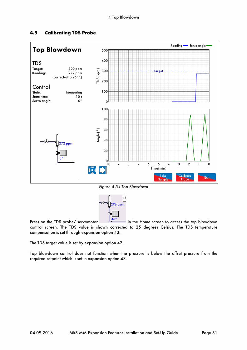
4 Top Blowdown
04.09.2016 Mk8 MM Expansion Features Installation and Set-Up Guide Page 81
4.5 Calibrating TDS Probe
Figure 4.5.i Top Blowdown
Press on the TDS probe/ servomotor in the Home screen to access the top blowdown control screen. The TDS value is shown corrected to 25 degrees Celsius. The TDS temperature compensation is set through expansion option 43. The TDS target value is set by expansion option 42. Top blowdown control does not function when the pressure is below the offset pressure from the required setpoint which is set in expansion option 47.

4 Top Blowdown
Page 82 Mk8 MM Expansion Features Installation and Set-Up Guide 04.09.2016
Figure 4.5.ii Calibrate TDS Probe
To calibrate the probe, press to calibrate the TDS probe. After taking a manual sample of
the TDS, enter the value into the keypad and press to enter this value. This value must be within 10% - 990% of the probe reading to avoid incorrect calibration. If there is an air lock, the TDS probe will not be calibrated as the reading will be 0ppm.To check the manual sample value against the now
calibrated probe value, press to sample the TDS using the probe. Note: Top blowdown control does not operate when the TDS probe is being calibrated, when a fresh sample is taken or when the burner is not firing.

4 Top Blowdown
04.09.2016 Mk8 MM Expansion Features Installation and Set-Up Guide Page 83
4.6 Faults
The table below show the faults which are directly related to the top blowdown function. For the full list of faults including errors, lockouts, alarms, warnings, setting conflicts and forced commission reasons, please see section 4 in the Mk8 MM Installation and Commissioning Guide. Fault Message Description Type 200 Top Blowdown Sensor
Communications Fault No comms with the top blowdown sensor
Warning
Check wiring and screen on terminals 3P+, 3P-, 3T+ and 3T- Check top blowdown sensor (TDS probe)
201 Top Blowdown Servo Position Error
Servomotor is outside of the commissioned range
Warning
Check wiring on terminals P-, TW, P+ Check signal cable form the MM to the servomotor is screened at one end Check that the servomotor is zeroed correctly
202 Top Blowdown Servo Movement Error
Servomotor moves when not expected and vice versa
Warning
Check wiring on terminals P-, TW, P+ and TBI, TBD Check servomotor drives in correct direction Check top blowdown valve is not stuck
250 Top Blowdown Reading High TDS value detected too high Warning
Check expansion option 46 and TDS value

5 Bottom Blowdown
Page 84 Mk8 MM Expansion Features Installation and Set-Up Guide 04.09.2016
5 BOTTOM BLOWDOWN
5.1 Overview
Bottom blowdown is used to remove solids which build up at the bottom of steam boilers. In the Autoflame system, there are options to either manage the blowdowns through automatic timings, or to manually trigger them. The programmable electronic automatic blowdown ensures repeatable blowdown timings, without the need of a compressed air supply. A pulsed bottom blowdown is used to disturb settled solids at the bottom of the boiler, making the evacuation effect more efficient. The timings and intervals of the bottom blowdowns are user configurable. The benefits of the Autoflame bottom blowdown system include:
Full stainless steel valve construction 24V DC Autoflame Unic 5 servomotor for control and repeatability Electronic proof of open/close end switches Lithium ion battery technology ensures guaranteed closure on power failure Total electronic operation – no compressed air supply Timed blowdown with manual/automatic operation Bottom blowdown sequence logging Up to 10 timed blowdowns over a 24 hour period Repeatable up to 10 times from 1 to 60 seconds for each blowdown ‘Parked’ position to reduce valve opening time Quick servomotor disconnect facility for manual actuation Rotary operation ensures water tight shutoff Sealing design concept ensures no leaks
To activate bottom blowdown on the Mk8 MM, the Bottom Blowdown expansion software feature must be unlocked. The activation code for the serial number of the MM will need to be purchased using part number MK8004, and uploaded to the unit via Download Manager software. Please see Autoflame PC Software Guide for more information on unlocking expansion features on the Mk8 MM using Download Manager software.

5 Bottom Blowdown
04.09.2016 Mk8 MM Expansion Features Installation and Set-Up Guide Page 85
5.2 Bottom Blowdown Reduction
5.2.1 Blowdown Savings
With a typical loss in steam generation of 3% from the conventional bottom blowdown management, Autoflame have developed a Bottom Blowdown Time Reduction feature to minimise these losses which occur when keeping the boiler heat transfer surfaces clean. It follows that blowdown time can be reduced as a function of the rate of steam generation. Silt and sludge formation within the boiler is always in ratio to work done or steam generation. Therefore the reduction in the blowdown valve open time can be made, as long as the reduced open time is in ratio to the evaporation rate or steam generation rate. Blowdown savings in the region of 1-2% are possible on total fuel usage (dependant on boiler
load) Blowdown timing automatically reduced in ratio to steam generation Blowdown timings set by users Operators may only trigger pre-set timings, eliminates excessive blowdown by operator Ensures minimal blowdown to satisfy removal of solids, silt and sludge
For time reduced bottom blowdown, steam flow metering and fuel flow metering is required. Steam flow metering can be set through expansion option 120, please see section 9 for more information. Fuel flow metering can be set through option 57.

5 Bottom Blowdown
Page 86 Mk8 MM Expansion Features Installation and Set-Up Guide 04.09.2016
5.2.2 Calculation for Bottom Blowdown Reduction
For timed reduced bottom blowdown with M.M. the maximum steam production used to base how the bottom blowdown time is scaled down to, is set through expansion option 36.4. The blowdown time is reduced according to the ratio of the actual steam production to the maximum steam production for that period. If the blowdown is calculated above the stored blowdown time set by the user in the bottom blowdown screen, than the extra time will get carried over to the next timed blowdown. This extra time will remain getting carried over to the following blowdowns until the steam production has lowered and the blowdown is therefore lowered. There can be up to 4 blowdowns over a 24 hour period, with each blowdown:
Blowdown Time BD1 BD2 BD3 BD4 Time between Blowdowns T1 T2 T3 T4
The configured blowdown time for that period x which has been set by the user is:
sec The time between the blowdowns which is sent by the user is:
Therefore over a 24 hour period:
24 The blowdown time for that 24 hour period is then:
So the maximum blowdown period can be calculated as:
24
The maximum steam flow which is set in expansion option 36.4 is:
The average steam flow for that period which is given from steam flow metering is:
The calculated steam flow ratio for that period is then:
The adjusted blowdown time according to steam production is then:
24
If the adjusted blowdown time is calculated higher than the maximum blowdown time, the time is carried over to the next blowdown operation:
Extra time is carried over to next blowdown operation
If the adjusted blowdown time is calculated lower than the minimum blowdown time set in expansion option 36.3, and expansion option 36.2 is set for minimum blowdown enforced then:
, then Minimum blowdown time is enforced
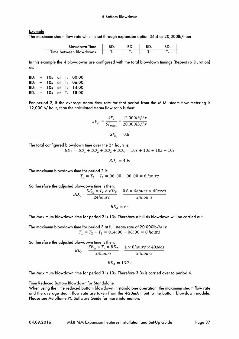
5 Bottom Blowdown
04.09.2016 Mk8 MM Expansion Features Installation and Set-Up Guide Page 87
Example The maximum steam flow rate which is set through expansion option 36.4 as 20,000lb/hour.
Blowdown Time BD1 BD2 BD3 BD4 Time between Blowdowns T1 T2 T3 T4
In this example the 4 blowdowns are configured with the total blowdown timings (Repeats x Duration) as: BD1 = 10s at T1 00:00 BD2 = 10s at T2 06:00 BD3 = 10s at T3 14:00 BD4 = 10s at T4 18:00 For period 2, if the average steam flow rate for that period from the M.M. steam flow metering is 12,000lb/ hour, than the calculated steam flow ratio is then:
12,000 ⁄
20,000 ⁄
0.6
The total configured blowdown time over the 24 hours is:
10 10 10 10
40 The maximum blowdown time for period 2 is:
06: 00 00: 00 6 So therefore the adjusted blowdown time is then:
240.6 6 40
24
6
The Maximum blowdown time for period 2 is 13s. Therefore a full 6s blowdown will be carried out. The maximum blowdown time for period 3 at full steam rate of 20,000lb/hr is:
014: 00 06: 00 8 So therefore the adjusted blowdown time is then:
241 8 40
24
13.3
The Maximum blowdown time for period 3 is 10s. Therefore 3.3s is carried over to period 4. Time Reduced Bottom Blowdown for Standalone When using the time reduced bottom blowdown in standalone operation, the maximum steam flow rate and the average steam flow rate are taken from the 4-20mA input to the bottom blowdown module. Please see Autoflame PC Software Guide for more information.

5 Bottom Blowdown
Page 88 Mk8 MM Expansion Features Installation and Set-Up Guide 04.09.2016
5.3 Installation Guidance
The bottom blowdown valve must be sized appropriately for blowdown rate required, which will be affected by the boiler pressure, size of blowdown line and blowdown line length from the boiler to the bottom blowdown vessel. The blowdown rate that is required for that boiler will vary according to the operating conditions, contaminants in the feed water and boiler design. The bottom blowdown valve must be installed along the blowdown pipeline according to local code and regulations. It is the responsibility of the factory trained technician or engineer to configure the bottom blowdown timings according to the specifications given by the boiler manufacturer. In multi-boiler systems where a bottom blowdown valve is fitted to each boiler, enabling Autoflame sequencing in option 16 will ensure that only boiler in that loop blows down at a given time. If a blowdown time is set the same on all the MMs in a sequencing loop, the MM with the lowest ID complete its blowdown first, followed by the rest of the MMs, sequentially. If Autoflame sequencing is not used for multi-boiler system requiring bottom blowdown in the UK, then valves must be interlocked; this ensures that only boiler can be blown down at one time. Please see local code and regulation on bottom blowdown in multi-boiler systems. The Autoflame bottom blowdown module (part number BBC70004) has a built in lithium ion battery, so should a power failure to the module, bottom blowdown fault or MM error occur, the battery will drive the servomotor to the closed position. The servomotor is powered by 24V DC from the bottom blowdown module. 5.3.1 Bottom Blowdown Valve
Water valves are universal for feed water, TDS, and bottom blowdown function. ½” and ¾” water level valves must be used with large servomotors. Industrial unic 05 servomotors must be used 1” and 1 ½”, and industrial unic 10 for 2” water valves. for water valves bigger than ¾”.
Maximum operating pressure: 29 Bar (425 PSI)Maximum operating temperature: 235OC (455OF) Please see section 3.2.1 for more information on water valves. Note: Please Valves and Servomotors manual for water level valve dimensions, drawings and information on service and maintenance.
Valve Type Size Part No. Servomotor
Large Unic 05 Unic 10
Threaded BSP/ NPT 15mm (½”) WLCVO15 • 20mm (¾”) WLCVO20 •
Flanged PN40 25mm (1”) WLCVO25/FL •
40mm (1 ½”) WLCVO40/FL • 50mm (2”) WLCVO50/FL •
Flanged ANSI 300lb 25mm (1”) WLCVO25/FLU •
40mm (1 ½”) WLCVO40/FLU • 50mm (2”) WLCVO50/FLU •

239mm(9.41”)
137.5mm(5.41”)
130mm(5.11”)
80mm(3.15”)
26mm(1.02”)
25mm(0.98”)
74.5mm(2.93”)
5 Bottom Blowdown
04.09.2016 Mk8 MM Expansion Features Installation and Set-Up Guide Page 89
5.3.2 Bottom Blowdown Module
If the bottom blowdown module is used with the MM, please follow the commissioning and blowdown timing configuration steps in section 5.4. If the bottom blowdown module is used as a standalone unit, please refer to the PC Software Guide for instructions on using the Bottom Blowdown Board Configurator software. Dimensions
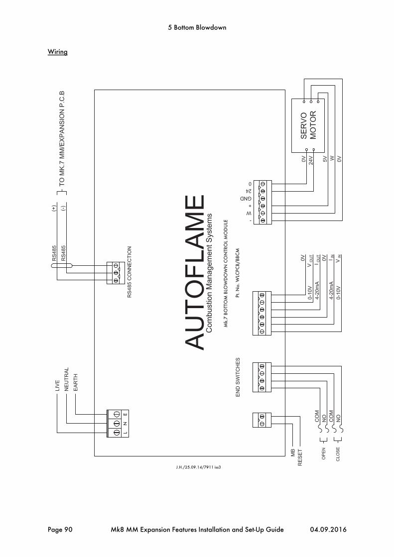
5 Bottom Blowdown
Page 90 Mk8 MM Expansion Features Installation and Set-Up Guide 04.09.2016
Wiring

5 Bottom Blowdown
04.09.2016 Mk8 MM Expansion Features Installation and Set-Up Guide Page 91
Terminal Description L Live N Neutral E Earth RS485 + Connection MM terminal 5T+ RS485 - Connection MM terminal 5T- S Screen at module MB Manual blowdown RESET Reset bottom blowdown module error OPEN COM/NO Volt-free connection for open position CLOSE COM/NO Volt-free connection for closed position VIN Voltage 0-10V input for steam production rating (standalone use) IIN Current 4-20mA input for steam production rating (standalone use) 0V Common for terminals VIN or IIN VOUT Voltage 0-10V output for bottom blowdown valve position 0V Common for terminals VOUT or IOUT - 0V supply to servomotor from MM W Signal from servomotor indicating position + +5V supply to servomotor from MM GND Ground/earth 24 +24V supply to servomotor from battery 0 +0V supply to servomotor from battery

5 Bottom Blowdown
Page 92 Mk8 MM Expansion Features Installation and Set-Up Guide 04.09.2016
5.4 Set-up
For a new installation, after checking the wiring, performing safety installation checks, and settings the options, parameters and expansion options, the servomotor closed position can be set in password protected Commissioning mode or Online Changes for an already commissioned system.
**WARNING** ANY PERSON WORKING ON A BOILER MUST BE ADEQUATELY TRAINED AND
HAVE A THOROUGH APPRECIATION OF THE BOILER PLANT. IT IS THE RESPONSIBILITY OF THE FACTORY TRAINED TECHNICIAN TO ENSURE THAT THE
SYSTEM OPERATION MEETS LOCAL CODES AND REGULATIONS.
When the bottom blowdown module is used as standalone, it must be configured using the bottom blowdown configurator PC software. Please see section 5 in the Autoflame PC Software Guide for more information. 5.4.1 Bottom Blowdown Settings
The bottom blowdown function can be set using an external solenoid valve or the bottom blowdown module, see expansion option 60. When a bottom blowdown time is due, the blowdown can be set to occur automatically, or by a pressing the manual trigger on the bottom blowdown screen, see expansion 61. Bottom blowdown reduction allows the timing of the blowdown to be adjusted according to the steam production, see expansion option 62. If there is no steam production when a blowdown time is due, the MM/module will ignore the blowdown or blow down the valve for a minimum duration, see expansion option 63. If using bottom blowdown reduction, the boiler steam production rating must be set and the fuel flow metering must be set and commissioned, see expansion option 64 and option 57. The industrial Unic servomotors which are used with the water valve for bottom blowdown are factory set with the closed position at 0.0O and open position at 90.0O. The default parked position is set the same as the closed position 0.0O, however this can be adjusted using the Bottom Blowdown Board Configurator software; refer to the PC Software Guide. The parked position is a near closed position. During a bottom blowdown event, the servomotor will move to the parked position rather than the closed position during the valve closed interval. This allows a not fully closed position to be set for the parked position, reducing the time take for the servomotor to drive to 90.0O for the valve open interval. The table below shows a summary of the bottom blowdown expansion options. Expansion Option Description 60 Bottom blowdown function 61 Bottom blowdown triggering 62 Bottom blowdown reduction 63 Minimum blowdown duration 64 Boiler steam production rating

5 Bottom Blowdown
04.09.2016 Mk8 MM Expansion Features Installation and Set-Up Guide Page 93
5.4.2 Setting Servomotor
When the bottom blowdown module is first enabled, the red and greed LEDs will flash on the modulate indicating a fault; there is fault because the module has not seen the servomotor go to the closed position yet. The warning ‘Bottom Blowdown Servo Not Commissioned’ will appear. The servomotor closed position can be set in password protected Commissioning mode or Online Changes.
Figure 5.4.2.i Servo in Other Position
Press in the Commission Mode screen or press in Online Changes and enter the password. The screen will show the current bottom blowdown servomotor angle. If the servomotor is not at the closed position, the message ‘Servo in Other Position’ will appear.

5 Bottom Blowdown
Page 94 Mk8 MM Expansion Features Installation and Set-Up Guide 04.09.2016
Figure 5.4.2.ii Servo Closed
The bottom blowdown module must see the servomotor at the closed position when first enabled, to clear the warning.
Press to drive the servomotor to the closed 0.0O position. Pressing will
nudge the servomotor in the closed or open direction. Pressing will stop the servomotor driving. When the servomotor is moving, the message ‘Servo Closing’ will appear, and when it has reached the closed position, the message will change to ‘Servo Closed.’ The potentiometer will not need to be zeroed on the industrial Unic servomotors.
Press to drive the servomotor towards the closed position using the battery power within the module. . A working battery will have 13V + in the cells, if this falls below 12.4V, there will not be enough voltage in the battery to drive the valve to the closed position should a power failure Bottom Blowdown Controller Main Power Fault will occur.
To test the battery operation, drive the servomotor to the closed position, then press . The valve will then be opened to the parked position using mains power, and then it is driven to the closed position using the battery power to test the battery. If the battery cannot drive he valve to the closed position, a Bottom Blowdown Servo Battery Drive Fault will occur.

5 Bottom Blowdown
04.09.2016 Mk8 MM Expansion Features Installation and Set-Up Guide Page 95
Figure 5.4.2.iii Servo Open
Press to drive the servomotor to the open 90.0O position.

5 Bottom Blowdown
Page 96 Mk8 MM Expansion Features Installation and Set-Up Guide 04.09.2016
Figure 5.4.2.iv Servo Parked
Press to drive the servomotor to drive to the servomotor to the parked position. The parked position is set using the Bottom Blowdown Board Configurator software, please see section 5 of the Autoflame PC Software Guide for more information.
Press once the bottom blowdown servomotor has been set for the closed and open position.
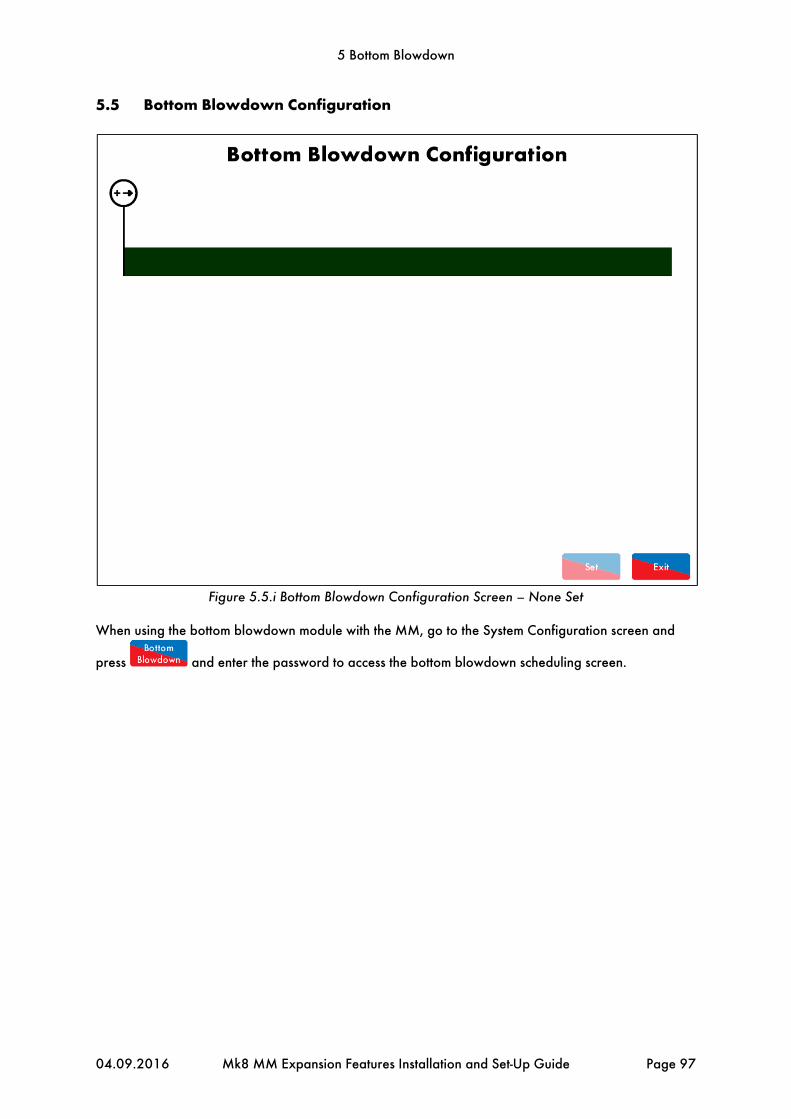
5 Bottom Blowdown
04.09.2016 Mk8 MM Expansion Features Installation and Set-Up Guide Page 97
5.5 Bottom Blowdown Configuration
Figure 5.5.i Bottom Blowdown Configuration Screen – None Set
When using the bottom blowdown module with the MM, go to the System Configuration screen and
press and enter the password to access the bottom blowdown scheduling screen.
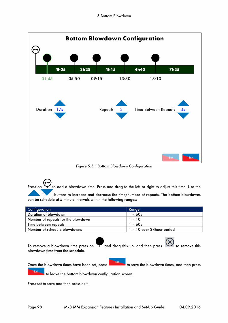
5 Bottom Blowdown
Page 98 Mk8 MM Expansion Features Installation and Set-Up Guide 04.09.2016
Figure 5.5.ii Bottom Blowdown Configuration
Press on to add a blowdown time. Press and drag to the left or right to adjust this time. Use the
buttons to increase and decrease the time/number of repeats. The bottom blowdowns can be schedule at 5 minute intervals within the following ranges: Configuration Range Duration of blowdown 1 – 60s Number of repeats for the blowdown 1 – 10 Time between repeats 1 – 60s Number of schedule blowdowns 1 – 10 over 24hour period
To remove a blowdown time press on and drag this up, and then press to remove this blowdown time from the schedule.
Once the blowdown times have been set, press to save the blowdown times, and then press
to leave the bottom blowdown configuration screen. Press set to save and then press exit.

5 Bottom Blowdown
04.09.2016 Mk8 MM Expansion Features Installation and Set-Up Guide Page 99
5.5.1 Bottom Blowdown Log
Figure 5.5.1.i Bottom Blowdown Log
Press on the bottom blowdown valve on the Home screen to access the bottom blowdown log screen. The bottom blowdown log stores the last 128 blowdowns, with the following information:
Type of blowdown – scheduled, manual Date and time blowdown scheduled Date and time blowdown occurred Number of repeats the and duration of blowdown
The bottom blowdown status shows a timer for when the next blowdown is due. If expansion option 61
is set for manual triggering, then when the next blowdown is due, the button must be pressed for the valve to blowdown. The status will then showing ‘waiting trigger’ until this is pressed or an line voltage input is detected on terminal MB on the bottom blowdown module. If the blowdown is not triggered, the log will show the scheduled blowdown as being ‘missed.’ If the bottom blowdown reduction has been enabled in expansion option 62, then the calculated reduced time will show on the log. The bottom blowdown log can be cleared in Online Changes.

5 Bottom Blowdown
Page 100 Mk8 MM Expansion Features Installation and Set-Up Guide 04.09.2016
5.6 Faults
The table below show the faults which are directly related to the bottom blowdown function. For the full list of faults including errors, lockouts, alarms, warnings, setting conflicts and forced commission reasons, please see section 4 in the Mk8 MM Installation and Commissioning Guide. Fault Message Description Type 300 Bottom Blowdown Controller
Comms No comms with bottom blowdown controller
Warning
Check bottom blowdown controller is powered on Check wiring and screen on terminals 5T+ and 5T-
301 Bottom Blowdown Controller Software Fault
Internal check failed Warning
Contact Autoflame
302 Bottom Blowdown Servo Closing Fault
No movement detected when bottom blowdown valve goes to close
Warning
Check wiring on terminals 5T+ and 5T- Check bottom blowdown valve is not stuck
303 Bottom Blowdown Servo Opening Fault
No movement detected when bottom blowdown valve goes to open
Warning
Check wiring on terminals 5T+ and 5T- Check bottom blowdown valve is not stuck
304 Bottom Blowdown Servo Battery Drive Fault
Battery has failed on bottom blowdown controller
Warning
Contact Autoflame
305 Bottom Blowdown Controller Main Power Fault
Main power has failed on bottom blowdown controller
Warning
Contact Autoflame
350 Bottom Blowdown Servo Not Commissioned
Bottom blowdown controller has not been requested to drive servomotor to closed since it was powered on
Warning
Commission bottom blowdown controller

6 Draught Control
04.09.2016 Mk8 MM Expansion Features Installation and Set-Up Guide Page 101
6 DRAUGHT CONTROL
6.1 Overview
6.1.1 Benefits of Draught Control
Draught control is used to manage the excess draught from stacks, in both fire-tube and water-tube applications, so heat transfer from the hot gases to the boiler tubes can be optimised. Both heat transfer rate and combustion rate depend on the motion of the flue gases; any changes in boiler pressure can affect the amount of combustion air entering the burner, possibly resulting in unburnt fuel. An excess of unburnt fuel can lead to unsteady combustion with dangerous consequences. A tall stack is susceptible to a changing pressure which is caused be stack temperature and wind velocity. The main benefits of maintain stack pressure through draught control include:
Improves heat transfer Improves combustion efficiency Reduces room heat loss Improves flame stability while reducing chance of pilot light failure Improves flame retention Reduce soot accumulation
6.1.2 Fully Integrated Draught Control
The Autoflame draught control stores the pressure conditions at the commissioning stage and modulates with the firing curve to maintain this, irrespective of changing firing rate and stack conditions. Normally there is a vertical main stack which has a horizontal cross connection from the boiler flue gas outlet; this is then connected into the main stack. The boiler only works at optimum efficiency when all of the conditions that effect its operation are held at good commissioned values. Therefore under the new arrangement, a butterfly valve driven by a positioning motor, is placed in the horizontal back flue typically two or three metres from the boiler. A differential pressure sensor is then inserted into the flue that is between the boiler outlet and the butterfly valve. As stack energy alters, the suction or pressure would vary at this point. It can be seen that by measuring the pressure of the draught at the position of the damper could be adjusted to bring the pressure or suction back to its commissioned value, the complete system would then be operating at optimum efficiency again.
Figure 6.1.2.i Stack with Draught Control

6 Draught Control
Page 102 Mk8 MM Expansion Features Installation and Set-Up Guide 04.09.2016
Figure 6.1.2.ii Autoflame Draught Control
After commissioning is completed, every fuel and air position will have a stack damper position together with a stored draft pressure. The stack pressure is controlled by air pressure sensor, stack damper and PI loop. When the system is in run mode the stack damper will be positioned according to the stored commissioning pressure. If the stack pressure reading measured by the differential air pressure sensor reads a different condition to the stored value, then the stack damper butterfly valve will be adjusted to ensure that the stack pressure is brought back to its commissioned value.
Figure 6.1.2.iii Draught Control Schematic

6 Draught Control
04.09.2016 Mk8 MM Expansion Features Installation and Set-Up Guide Page 103
6.2 Draught Control Operation
6.2.1 Overview
To activate draught control on the Mk8 MM, the Draught Control expansion software feature must be unlocked. The activation code for the serial number of the MM will need to be purchased using part number MK8005, and uploaded to the unit via Download Manager software. Please see Autoflame PC Software Guide for more information on unlocking expansion features on the Mk8 MM using Download Manager software. The draught servomotor can be set on the Mk8 MM for servomotor movement only or draught control with a pressure sensor to maintain the stack pressure. The draught control trim functionality follows the same ideology to the EGA, where corrections are made to air damper to compensate for the changes in exhaust gas values from their commissioned values, caused by fluctuations in ambient conditions. For Autoflame draught control, corrections are made to the stack damper to compensate for changes in wind and ambient conditions which cause the stack pressure to differ from the commissioned stack pressure along the fuel curve. Once the burner starts up and the main flame stabilised, there is a time delay where no draught control operation occurs, set in expansion option 85. After this time delay elapses, as the air going into the burner is increased from low fire to high fire, the boiler pressure may change and the draught servomotor will move to follow these changes as commissioned. If the atmospheric or stack pressures have changed from their commissioned values along the curve, the air damper will either move in the open, or close direction to adjust the air pressure in the stack back to its set value. The smallest angle that the draught damper can drive to while running is defined by expansion option 83; when the burner turns off, the draught damper will go to commissioned closed position to maintain heat within the boiler. If draught control is optioned off after being commissioned, then the draught servomotor will continue to move to its commissioned angular position as the burner fires. 6.2.2 Deactivation Window
There is a deactivation window, outside of which no trim occurs, and the air damper remains at the previously trimmed position until back within the window and trim is required. This deactivation window is defined by expansion options 85 - delay before compensation and 86 – commissioned angle variation tolerance. If the draught servomotor has moved more than the set angular degrees “x”, within the time period set “y”, than no trim functionality will operate, if trim has been performed prior to this deactivation then the trim is carried forward. For example, when the burner is first switched on, if the burner comes out of warming in lead-lag control, or is switched from low flame hold to auto mode, there is a high load demand. In these situations the firing rate may ramp up quickly to meet load demand, at this point if the draught servomotor is required to move greater than the commissioned angle variation tolerance and quicker than the delay before compensation then no trim functionality will occur and any trim % will be carried forward.

6 Draught Control
Page 104 Mk8 MM Expansion Features Installation and Set-Up Guide 04.09.2016
Figure 6.2.2.i Deactivation Window

6 Draught Control
04.09.2016 Mk8 MM Expansion Features Installation and Set-Up Guide Page 105
6.2.3 Draught Control Trim
If within the trim window, the trim functionality is controlled by the maximum forward or backward trim set in expansion option 84 maximum compensation, and also by the PI settings in expansion options 90 proportional band and 91 integral time. The maximum compensation set in expansion option 84 is the maximum percentage of the commissioned draught servomotor angle to which the stack damper will trim negative or positive.
Figure 6.2.3.i Draught Control Trim

6 Draught Control
Page 106 Mk8 MM Expansion Features Installation and Set-Up Guide 04.09.2016
Figure 6.2.3.ii Draught Trim
Figure 6.2.3.ii shows the draught trim operation to maintain the commissioned draught pressure.

6 Draught Control
04.09.2016 Mk8 MM Expansion Features Installation and Set-Up Guide Page 107
6.3 Set-Up
6.3.1 Configuration
The draught control servomotor positions, and the stack pressure if using draught control is enabled, is set during the burner commissioning procedure. Due to softened error checking, it is recommended to use an industrial unic servomotor for the draught channel; however a small/large servomotor can be used for smaller applications. The servomotor will need to be sized according to the torque requirements of the stack damper. If draught control is enabled in expansion 82, then a Mk8 air pressure sensor is also required, part number MM80005. For information on installing the draught servomotor and air pressure sensor, please see section 6.1.2. For dimensions and technical specification for the draught servomotor, please refer to the Valves and Servomotors manual, and the MM Application Possibilities manual for the Mk8 air pressure sensor. The table below shows the MM terminals for the draught servomotor and Mk8 air pressure sensor. Terminal Description DT+ Digital communication connections from draught control pressure sensor DT- Digital communication connections from draught control pressure sensor DP- 0V supply to draught control pressure sensor and draught control servomotor DP+ +12V supply to draught control pressure sensor and draught control servomotor DPW Signal from draught control servomotor, indicating position DCI Switched neutral – drives draught servomotor clockwise DCD Switched neutral – drives draught servomotor counter clockwise When wiring the air pressure sensor, the screen is connected through the casing of the lead and through the sensor; therefore the flying lead should be connected to the MM without a screen. The screen should be carried through until the connection to the MM; the screen should not be connected to the S terminal. The table below shows the expansions options to be set when using draught control. Expansion Option Description Setting 80 Draught control servo channel 1 81 Draught servo control method Depends on servomotor used 82 Draught control function As required 83 Draught servo minimum angle As required 84 Maximum compensation As required 85 Delay before compensation As required 86 Commissioned angle variation tolerance As required 87 Pressure tolerance before fault As required 88 Action on pressure sensor fault As required 89 Pressure sensor filter time As required 90 Proportional band As required 91 Integral time As required

6 Draught Control
Page 108 Mk8 MM Expansion Features Installation and Set-Up Guide 04.09.2016
6.3.2 Ways of Using Draught Servomotor
The draught servomotor can be used for draught control trim with an air pressure sensor, or as a draught servomotor which drives to commissioned positions along the firing curve.
Figure 6.3.2.i Draught Servomotor
Figure 6.3.2.i shows the draught servomotor enabled without draught control trim.

6 Draught Control
04.09.2016 Mk8 MM Expansion Features Installation and Set-Up Guide Page 109
6.4 Commissioning Draught Control
6.4.1 Commissioning Checks
Important Note: Prior to commissioning, the fuel and air servomotors must be calibrated to ensure that the position of the valves and damper correspond to the potentiometer feedback signal as displayed on the MM. When the valve is fully closed, the MM should display zero degrees. If it does not, please adjust the servomotor potentiometer. The commissioning procedure as described must be strictly adhered to. Anybody commissioning an MM must be trained in operating combustion equipment safely. The Autoflame products must only be installed, set up, commissioned and adjusted by an Autoflame certified technical engineer. The fundamental idea of the system is to set a fuel valve position and then set a corresponding air damper position. Care must be taken when adjusting the fuel and air positions so as not to create any unstable or hazardous combustion conditions, e.g. moving the fuel valve to the open position without increasing the air damper position. Improper use may result in property damage, serious physical injury or death. If the MM is commissioned without an EGA then a combustion analyser is required to check the exhaust gases. If the system does have an EGA, then a combustion analyser is not necessary as the EGA performs all normal exhaust gas measurements. When burning oil a smoke detection device is also necessary to check that the smoke generated is within safe limits. To implement commissioning efficiently, arrange for a substantial load on the boiler. The commissioning procedure can be interrupted due to excess temperature or pressure, causing the burner to turn off; the commissioning data entered so far is not lost, provided power is not lost to the MM. When the burner is called back on, the system starts automatically and commissioning can proceed from where it was left. Once a start position has been entered, the high fire position is entered next, then descending fuel/air positions are entered consecutively until finally the low fire position is entered. CH1 and CH2 positions must always be less than the ones previously entered; however CH3 to CH7 can be set lower or higher than the previous position. CH7 is used for the draught servomotor (unlockable expansion feature). CH1 Fuel valve CH2 Air damper CH3 Auxiliary Servomotor CH4 Auxiliary Servomotor CH5 VSD 1 CH6 VSD 2 CH7 Draught servomotor (unlockable expansion feature) On a newly installed system the following procedures should be carried out as listed:
1. Check all interconnecting wiring between the MM and external components is correct. 2. Set options, parameters and expansion options required 3. Commission bottom blowdown module if optioned. 4. Commission water level probes and external level sensor if optioned. 5. Set up servomotors. 6. Program fuel/air positions.
On a previously commissioned system is it possible to omit steps 1 to 5. Please refer to section 3.8.1 for commissioning checks.

6 Draught Control
Page 110 Mk8 MM Expansion Features Installation and Set-Up Guide 04.09.2016
6.4.2 Commissioning Screen
Figure 6.4.2.i Commissioning Draught Servomotor
To commission the draught servomotor, go to the commissioning screen by pressing in the Commission mode screen. In addition to the CH7, a draught pressure is visible on the MM screen whilst commissioning if draught control is enabled rather than draught servomotor. Use CH7 to change the draught damper angle to maintain the boiler’s ideal stack pressure throughout the commissioning curve. Note: If on the day of commission, there are extreme conditions such as heavy wind, the stored angles for the draught damper along the commissioned curve may not be relevant for a day without heavy wind over the stack. Go through the burner commissioning process as described in section 3.4 in the Mk8 MM Installation and Commissioning Guide, and entered the draught servomotor positions as required. The draught servomotor cannot be set at a position lower than the minimum angle set in expansion option 83, all positions except for the closed which can be set lower.

6 Draught Control
04.09.2016 Mk8 MM Expansion Features Installation and Set-Up Guide Page 111
6.5 Faults
The table below show the faults which are directly related to the draught control function. For the full list of faults including errors, lockouts, alarms, warnings, setting conflicts and forced commission reasons, please see section 4 in the Mk8 MM Installation and Commissioning Guide. Fault Message Description Type 400 Draught Pressure Sensor
Timeout No comms within 2 seconds from draught pressure sensor
Alarm/Warning – option 88
Check wiring and screen on terminals DT+, DT-, DP- and DP+ Warning if expansion option 88 is set to 1
410 Draught Pressure Outside Tolerance
Pressure is outside of set tolerance Alarm/Warning – option 88
Check expansion option 87 Check draught air pressure sensor

7 Remote Control
Page 112 Mk8 MM Expansion Features Installation and Set-Up Guide 04.09.2016
7 REMOTE CONTROL
7.1 Overview
To access data remotely from the Mk8 MM, this can be done by either connecting to a MK7 DTI, or by using direct Modbus. Direct Modbus cannot be used with sequencing or Mk7 DTI. The MM Direct Modbus expansion feature must be unlocked. To activate direct Modbus on the Mk8 MM, the Direct Modbus expansion software feature must be unlocked. The activation code for the serial number of the MM will need to be purchased using part number MK8006, and uploaded to the unit via Download Manager software. Please see Autoflame PC Software Guide for more information on unlocking expansion features on the Mk8 MM using Download Manager software. There are a limited number of Modbus addresses available in the Mk8 MM, which can be accessed directly without the need for a DTI. When using Modbus direct e.g. connecting to Building Management System from the MM without a DTI, then neither Autoflame Intelligent Boiler Sequencing nor the DTI can be used. The MM communicates using an RS485 data link from terminals 27 (-ve) and 28 (+ve). Beldon 9501 data cable is recommended. Up to 10 MMs can be linked to together and connected to a Building Management System via terminals 27 and 28. Each Mk8 MM will need to be set with an individual Modbus device ID by setting expansion option 104. The maximum block of addresses the MM can read and write to is 127, as per Modbus having a built-in limit of 255 byte packets. If the MM does not receive any Modbus commands for 60 seconds, the Modbus goes ‘offline.’ You can keep the Modbus ‘online’ with a simple instruction, such as polling or setting a single value to that individual MM. If the Modbus is ‘offline’ then remote setpoint and firing rate set via Modbus will be disabled. The only exception is the enable/disable burner which changes the enable/disable button on the MM on the home screen, as this change will last until the Modbus state is changed again or the enable/disable button is pressed again. If the MM is powered off or the communications is lost, the Modbus address values from the unit will not be true.

7 Remote Control
04.09.2016 Mk8 MM Expansion Features Installation and Set-Up Guide Page 113
7.2 Configuration
The following expansion options will need to be set on the Mk8 MM for direct Modbus. Expansion Option Description Setting 100 Sequencing/DTI or Modbus function 1 101 Modbus baud rate As required 102 Modbus parity setting As required 103 Modbus stop bits setting As required 104 Modbus device ID As required 105 Binary format As required The following terminals are used for direct Modbus. Terminal Description 27 RS485 - 28 RS485 + S Screen

7 Remote Control
Page 114 Mk8 MM Expansion Features Installation and Set-Up Guide 04.09.2016
7.3 Modbus Addresses
There are 4 types of Modbus addresses: 0x Read/Write digital outputs – off/on commands
These are binary values and have a 0/1 value indicating an off/on or no/yes value. 1x Read digital inputs – off/on signals/indications
3x Read analogue inputs – variable data in
These are multiple integer values and can have a value of 0 to 65534 and do not contain decimal points i.e. channel 1position Modbus value is 900 which is equivalent to 90.0O
4x Read/Write analogue outputs – variable adjustments
Address Description Type 00001 Enable/Disable MM Read/write digital
0 = Burner is enabled, 1 = Burner is disabled Value changes state of enable/disable button on MM home screen; changes are kept if MM
loses comms with Modbus device sending commands 10194 Running Interlock Status Read digital
0 = Running interlock (T53) is off 1 = Running interlock (T53) is on
10217 EGA Trim Optioned Read digital
0 = Trim not optioned, 1 = Trim optioned Returns value 0 when option 12 is set for monitoring only.
10218 EGA is Trimming Read digital
0 = EGA not trimming, 1 = EGA is trimming Returns value 0 is actual temperature/pressure is below trim threshold
10219 EGA Cooler Ready Read digital
0 = Cooler is ready, 1 = Cooler is not ready Returns value 0 if EGA is an error state
10220 EGA Ambient Temp OK Read digital
0 = Temperature OK, 1 = Temperature not OK
10221 EGA NO2 On Read digital
0 = NO2 cell not optioned, 1 = NO2 cell optioned See option 36, valid for Mk7 EGA only
10222 EGA SO2 On Read digital
0 = SO2 cell not optioned, 1 = SO2 cell optioned See option 36, valid for Mk7 EGA only
10224 EGA OK to Sample Read digital
0 = EGA is not sampling, 1 = EGA is sampling
10233 Hand Mode Read digital
0 = MM not in hand mode, 1 = MM in hand mode
10234 Low Flame Hold Read digital
0 = MM not in low flame hold, 1 = MM in low flame hold
10242 Disabled Status Read digital
0 = Burner enabled, 1 = Burner disabled Returns state of enable/disable button on MM home screen and same value as address 00001

7 Remote Control
04.09.2016 Mk8 MM Expansion Features Installation and Set-Up Guide Page 115
Address Description Type 12001 Water Level Optioned Read digital
0 = Water level not optioned, 1 = water level optioned
12002 Units Imperial or Metric Read digital
0 = Imperial,1 = Metric
12003 Feedwater Pump State Read digital
0 = Pump off, 1 = Pump on
12004 TDS Units Read digital
0 = ppm, 1 = μS/cm
12005 Water Level Ready Read digital
0 = No, either water level is not optioned or a water level fault is active 1 = Yes, requires water level to be optioned and no water level faults
12006 TDS Optioned Read digital
0 = TDS not optioned, 1 = TDS optioned
12007 First Out 1 State Read digital
0 = First Out 1 not active, 1 = First Out 1 active (does not mean first out has been cleared)
12008 First Out 2 State Read digital
0 = First Out 2 not active, 1 = First Out 2 active (does not mean first out has been cleared)
12009 First Out 3 State Read digital
0 = First Out 3 not active, 1 = First Out 3 active (does not mean first out has been cleared)
12010 First Out 4 State Read digital
0 = First Out 4 not active, 1 = First Out 4 active (does not mean first out has been cleared)
12011 First Out 5 State Read digital
0 = First Out 5 not active, 1 = First Out 5 active (does not mean first out has been cleared)
12012 First Out 6 State Read digital
0 = First Out 6 not active, 1 = First Out 6 active (does not mean first out has been cleared)
12013 First Out 7 State Read digital
0 = First Out 7 not active, 1 = First Out 7 active (does not mean first out has been cleared)
12014 First Out 8 State Read digital
0 = First Out 8 not active, 1 = First Out 8 active (does not mean first out has been cleared)
12015 First Out 9 State Read digital
0 = First Out 9 not active, 1 = First Out 9 active (does not mean first out has been cleared)
12016 First Out 10 State Read digital
0 = First Out 10 not active, 1 = First Out 10 active (does not mean first out has been cleared)
12017 First Out 11 State Read digital
0 = First Out 11 not active, 1 = First Out 11 active (does not mean first out has been cleared)
12018 First Out 12 State Read digital
0 = First Out 12 not active, 1 = First Out 12 active (does not mean first out has been cleared)
12019 First Out 13 State Read digital
0 = First Out 13 not active, 1 = First Out 13 active (does not mean first out has been cleared)
12020 First Out 14 State Read digital
0 = First Out 14 not active, 1 = First Out 14 active (does not mean first out has been cleared)
12021 First Out 15 State Read digital
0 = First Out 15 not active, 1 = First Out 15 active (does not mean first out has been cleared)

7 Remote Control
Page 116 Mk8 MM Expansion Features Installation and Set-Up Guide 04.09.2016
Address Description Type 30101 Load Index Read analogue
Firing rate %
30102 Firing Status Read analogue
0 = Non-modulating, 1 = Modulating Returns value 0 single point change, fuel flow metering and commissioning
30104 Burner Rating Read analogue
MW x 10 Metric units determined from fuel flow metering
30105 Actual Value Read analogue
Metric: temperature OC, pressure Bar x 10, low pressure Bar x 100 Imperial: temperature OF, pressure PSI, low pressure PSI x 10
30106 Required Value Read analogue
Metric: temperature OC, pressure Bar x 10, low pressure Bar x 100 Imperial: temperature OF, pressure PSI, low pressure PSI x 10
30107 Selected Fuel Read analogue
0 = Fuel 1, 1 = Fuel 2, 2 = Fuel 3, 3 = Fuel 4
30109 Channel 1 Position Read analogue
Degrees x 10 Range is -6.0O to 96.0O
30110 Channel 2 Position Read analogue
Degrees x 10 Range is -6.0O to 96.0O
30111 Channel 3 Position Read analogue
Degrees x 10 Range is -6.0O to 96.0O
30112 Channel 4 Position Read analogue
Degrees x 10 Range is -6.0O to 96.0O
30113 MM Error Number Read analogue
0 = System is does not have an error, N = error number, check error codes
30114 Multi-Burner Id Read analogue
MM Id number set in option 44
30115 EGA Current O2 Value Read analogue
% x 10
30116 EGA Current CO2 Value Read analogue
% x 10
30117 EGA Current CO Value Read analogue
ppm x 10
30118 EGA Current Exhaust Gas Temperature Read analogue
Metric: temperature x 10 OC Imperial: temperature x 10 OF
30119 EGA Current Efficiency Value Read analogue
% x 10
30120 EGA Current NO Value Read analogue
ppm x 10

7 Remote Control
04.09.2016 Mk8 MM Expansion Features Installation and Set-Up Guide Page 117
Address Description Type 30121 EGA Current SO2 Value Read analogue
ppm x 10
30122 EGA Commissioned O2 Value Read analogue
% x 10
30123 EGA Commissioned CO2 Value Read analogue
% x 10
30124 EGA Commissioned CO Value Read analogue
ppm x 10
30125 EGA Commissioned Exhaust Gas Temperature Read analogue
Metric: temperature x 10 OC Imperial: temperature x 10 OF
30126 EGA Commissioned Efficiency Value Read analogue
% x 10
30127 EGA Commissioned NO Value Read analogue
ppm x 10
30128 EGA Commissioned SO2 Value Read analogue
ppm x 10
30129 EGA Error Code Read analogue
0 = EGA does not have a fault, N = EGA error
30130 Minimum Remote Setpoint Read analogue
Metric: temperature OC, pressure Bar x 10, low pressure Bar x 100 Imperial: temperature OF, pressure PSI, low pressure PSI x 10
30131 Maximum Remote Setpoint Read analogue
Metric: temperature OC, pressure Bar x 10, low pressure Bar x 100 Imperial: temperature OF, pressure PSI, low pressure PSI x 10
30132 Current Flow Thousands Read analogue
Metric kW, imperial MMBTU/hr x 1000 Remainder after whole number of MW or MMBTU/hr x 1000 taken away. E.g. 1.5MW gives
500 value and 15.1MMBTU/hr gives 100 value 30133 Current Flow Millions Read analogue
Metric MW, imperial MMBTU/hr Whole number of MW or MMBTU/hr. E.g. 1.5MW gives 1 value and 15.1MMBTU/hr gives
15 value 30134 Fuel 1 Flow Total Thousands Read analogue
Metric kW/hr, imperial MMBTU/hr Remainder after whole number of MW/hr or MMBTU x 1000 taken away, x 1000. E.g.
1.5MW/hr gives 500 value and 15.1MMBTU gives 100 value 30135 Fuel 1 Flow Total Millions Read analogue
Metric MW/h, imperial MMBTU Whole number of MW/hr or MMBTU. E.g. 1.5MW/hr gives 1 value and 15.1MMBTU gives
15 value 30136 Fuel 1 Flow Total Billions Read analogue
Metric GW/hr, imperial MMBTU / 1000 Whole number of GW/hr or MMMBTU E.g. 1.5MW/hr gives 0 value and 15.1MMBTU gives 0
value
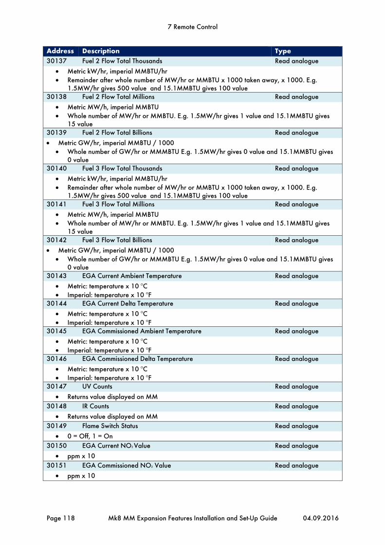
7 Remote Control
Page 118 Mk8 MM Expansion Features Installation and Set-Up Guide 04.09.2016
Address Description Type 30137 Fuel 2 Flow Total Thousands Read analogue
Metric kW/hr, imperial MMBTU/hr Remainder after whole number of MW/hr or MMBTU x 1000 taken away, x 1000. E.g.
1.5MW/hr gives 500 value and 15.1MMBTU gives 100 value 30138 Fuel 2 Flow Total Millions Read analogue
Metric MW/h, imperial MMBTU Whole number of MW/hr or MMBTU. E.g. 1.5MW/hr gives 1 value and 15.1MMBTU gives
15 value 30139 Fuel 2 Flow Total Billions Read analogue
Metric GW/hr, imperial MMBTU / 1000 Whole number of GW/hr or MMMBTU E.g. 1.5MW/hr gives 0 value and 15.1MMBTU gives
0 value 30140 Fuel 3 Flow Total Thousands Read analogue
Metric kW/hr, imperial MMBTU/hr Remainder after whole number of MW/hr or MMBTU x 1000 taken away, x 1000. E.g.
1.5MW/hr gives 500 value and 15.1MMBTU gives 100 value 30141 Fuel 3 Flow Total Millions Read analogue
Metric MW/h, imperial MMBTU Whole number of MW/hr or MMBTU. E.g. 1.5MW/hr gives 1 value and 15.1MMBTU gives
15 value 30142 Fuel 3 Flow Total Billions Read analogue
Metric GW/hr, imperial MMBTU / 1000 Whole number of GW/hr or MMMBTU E.g. 1.5MW/hr gives 0 value and 15.1MMBTU gives
0 value 30143 EGA Current Ambient Temperature Read analogue
Metric: temperature x 10 OC Imperial: temperature x 10 OF
30144 EGA Current Delta Temperature Read analogue
Metric: temperature x 10 OC Imperial: temperature x 10 OF
30145 EGA Commissioned Ambient Temperature Read analogue
Metric: temperature x 10 OC Imperial: temperature x 10 OF
30146 EGA Commissioned Delta Temperature Read analogue
Metric: temperature x 10 OC Imperial: temperature x 10 OF
30147 UV Counts Read analogue
Returns value displayed on MM
30148 IR Counts Read analogue
Returns value displayed on MM
30149 Flame Switch Status Read analogue
0 = Off, 1 = On
30150 EGA Current NO2 Value Read analogue
ppm x 10
30151 EGA Commissioned NO2 Value Read analogue
ppm x 10

7 Remote Control
04.09.2016 Mk8 MM Expansion Features Installation and Set-Up Guide Page 119
Address Description Type 30801 Fuel 4 Flow Total Thousands Read analogue
Metric kW/hr, imperial MMBTU/hr Remainder after whole number of MW/hr or MMBTU x 1000 taken away, x 1000. E.g.
1.5MW/hr gives 500 value and 15.1MMBTU gives 100 value 30802 Fuel 4 Flow Total Millions Read analogue
Metric MW/h, imperial MMBTU Whole number of MW/hr or MMBTU. E.g. 1.5MW/hr gives 1 value and 15.1MMBTU gives
15 value 30803 Fuel 4 Flow Total Billions Read analogue
Metric GW/hr, imperial MMBTU / 1000 Whole number of GW/hr or MMMBTU E.g. 1.5MW/hr gives 0 value and 15.1MMBTU gives
0 value 30804 VSD 1 Output Read analogue
mA x 10 or V x 10
30805 VSD 1 Input Read analogue
mA x 10 or V x 10
30806 VSD 2 Output Read analogue
mA x 10 or V x 10
30807 VSD 2 Input Read analogue
mA x 10 or V x 10
30808 Channel 7 Position Read analogue
Degrees x 10 Range is -6.0O to 96.0O
30830 Lockout Number Read analogue
0 = System is not in lockout, N = lockout number
30831 Fuel 1 Type Read analogue
0 = Gas, 1 = Oil Option/ parameter 150 value
30832 Fuel 2 Type Read analogue
0 = Gas, 1 = Oil Option/parameter 151 value
30833 Fuel 3 Type Read analogue
0 = Gas, 1 = Oil Option/parameter 152 value
30834 Fuel 4 Type Read analogue
0 = Gas, 1 = Oil Option/parameter 153 value
30839 Fuel 1 Hours Run Read analogue
Completed hours
30840 Fuel 2 Hours Run Read analogue
Completed hours
30841 Fuel 3 Hours Run Read analogue
Completed hours
30842 Fuel 4 Hours Run Read analogue
Completed hours

7 Remote Control
Page 120 Mk8 MM Expansion Features Installation and Set-Up Guide 04.09.2016
Address Description Type 30843 Fuel 1 Start-ups Read analogue
Start-ups
30844 Fuel 2 Start-ups Read analogue
Start-ups
30845 Fuel 3 Start-ups Read analogue
Start-ups
30846 Fuel 4 Start-ups Read analogue
Start-ups
30847 Current Air Pressure Read analogue
mbar x 10, “wg x 10 Parameter 43 value
30849 Current Gas Pressure Read analogue
mbar x 10, “wg x 10, PSI x 100 parameter 41 value
32001 Capacitance Probe 1 Signal Read analogue
Hz reading
32002 Capacitance Probe 1 Reading on MM Read analogue
Metric: mm Imperial: inches x 10
32005 Capacitance Probe 2 Signal Read analogue
Hz reading
32006 Capacitance Probe 2 Reading on MM Read analogue
Metric: mm Imperial: inches x 10
32009 Alarm Status Read analogue
0 = No alarm, 1 = Alarm
32010 Warning Status Read analogue
0 = No warning, 1 = Warning
32012 Alarm Code Read analogue
0 = System is not in alarm, N = alarm number
32013 Warning Status Read analogue
0 = System is not in warning, N = warning number
32014 Steam Temperature (OC) Read analogue
OC
32015 Feed Water Temperature (OC) Read analogue
OC
32016 Steam Flow Rate (lb/hr) Read analogue
lb per hour
32017 Heat to Steam Output (BTU per lb) Read analogue
BTU per lb
32018 Feed Water Control Element Percent Read analogue
%
32020 Sudden Pressure Drop Read analogue
0 = Sudden pressure drop not detected, 1 = sudden pressure drop detected
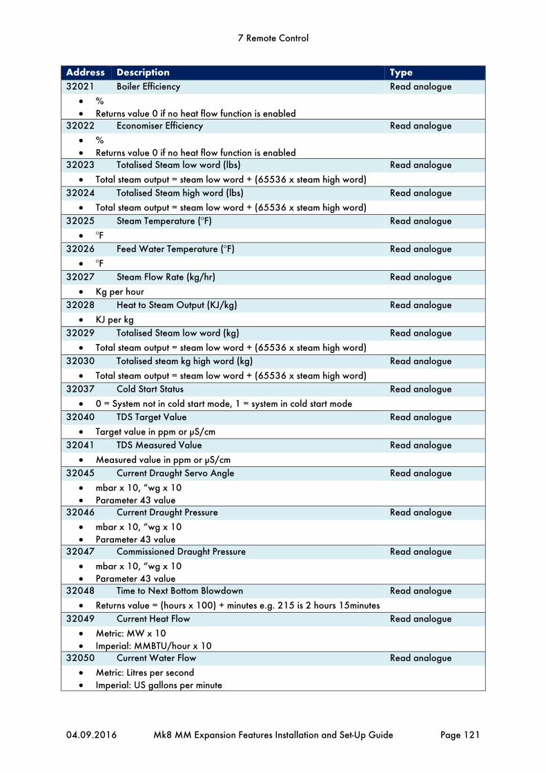
7 Remote Control
04.09.2016 Mk8 MM Expansion Features Installation and Set-Up Guide Page 121
Address Description Type 32021 Boiler Efficiency Read analogue
% Returns value 0 if no heat flow function is enabled
32022 Economiser Efficiency Read analogue
% Returns value 0 if no heat flow function is enabled
32023 Totalised Steam low word (lbs) Read analogue
Total steam output = steam low word + (65536 x steam high word)
32024 Totalised Steam high word (lbs) Read analogue
Total steam output = steam low word + (65536 x steam high word)
32025 Steam Temperature (OF) Read analogue
OF
32026 Feed Water Temperature (OF) Read analogue
OF
32027 Steam Flow Rate (kg/hr) Read analogue
Kg per hour
32028 Heat to Steam Output (KJ/kg) Read analogue
KJ per kg
32029 Totalised Steam low word (kg) Read analogue
Total steam output = steam low word + (65536 x steam high word)
32030 Totalised steam kg high word (kg) Read analogue
Total steam output = steam low word + (65536 x steam high word)
32037 Cold Start Status Read analogue
0 = System not in cold start mode, 1 = system in cold start mode
32040 TDS Target Value Read analogue
Target value in ppm or μS/cm
32041 TDS Measured Value Read analogue
Measured value in ppm or μS/cm
32045 Current Draught Servo Angle Read analogue
mbar x 10, “wg x 10 Parameter 43 value
32046 Current Draught Pressure Read analogue
mbar x 10, “wg x 10 Parameter 43 value
32047 Commissioned Draught Pressure Read analogue
mbar x 10, “wg x 10 Parameter 43 value
32048 Time to Next Bottom Blowdown Read analogue
Returns value = (hours x 100) + minutes e.g. 215 is 2 hours 15minutes
32049 Current Heat Flow Read analogue
Metric: MW x 10 Imperial: MMBTU/hour x 10
32050 Current Water Flow Read analogue
Metric: Litres per second Imperial: US gallons per minute

7 Remote Control
Page 122 Mk8 MM Expansion Features Installation and Set-Up Guide 04.09.2016
Address Description Type 32051 External Level Sensor Reading Depth Read analogue
Metric: mm Imperial: inches x 10
32052 Second Low Probe Input Read analogue
0 = No water is detected, 1 = water is detected
32053 Auxiliary High Water Input Read analogue
0 = Input not active, 1 = input active
32054 Auxiliary 1st Low Input Read analogue
0 = Input not active, 1 = input active
32055 Auxiliary 2nd Low Input Read analogue
0 = Input not active, 1 = input active
32056 Combined Water level Reading Depth Read analogue
Metric: mm Imperial: inches x 10
40001 Remote Required Setpoint Read/write analogue
Metric: temperature OC, pressure Bar x 10, low pressure Bar x 100 Imperial: temperature OF, pressure PSI, low pressure PSI x 10 After 1 minute of no Modbus communications to the unit, the M.M. will ignore this required
value and use the required setpoint set on the M.M.’s status screen. 40121 Remote Firing Rate Read/write analogue
% 40131 must be set to 1 to change the firing rate remotely
40131 Remote Firing Rate Enable Read/write analogue
0 = Remote firing rate disabled, 1 = remote firing rate enabled

8 First Outs
04.09.2016 Mk8 MM Expansion Features Installation and Set-Up Guide Page 123
8 FIRST OUTS
8.1 Overview
When the control circuit has a long series chain of various thermostats and switching elements, it can be difficult to identify which element has opened the control circuit. It is possible to monitor a maximum of 15 different inputs in a series control circuit on the Mk8 MM. Each input responds to a signal voltage of between 110V to 230Vac. To activate first outs on the Mk8 MM, the First Out Annunciation software feature must be unlocked. The activation code for the serial number of the MM will need to be purchased using part number MK8007, and uploaded to the unit via Download Manager software. Please see Autoflame PC Software Guide for more information on unlocking expansion features on the Mk8 MM using Download Manager software. The first outs can be configured for active input state low or high. When the active input state is set to low, the first out is triggered when the input is low, and when it is set for high, it will be triggered when the input is high. The table below shows the functions that can be set for the first outs. Function When Active Description Disabled Does not function. Monitor Burner continues firing, but the events will be logged. Non-recycle Burner stops firing and the first out must be reset for the burner to restart. Recycle Burner stops firing and restarts automatically when the input state changes. Stop EGA Sampling Burner continues firing, but the EGA stops sampling. Stops EGA Trimming Burner continues firing, but the EGA trim stops operating.
The first out logs can be displayed by pressing in the Home screen, which will give information on the trigger time and of the first out and when it was reset.

8 First Outs
Page 124 Mk8 MM Expansion Features Installation and Set-Up Guide 04.09.2016
8.2 Configuration
8.2.1 Running Interlock Circuit
The burner will shut down when the MM detects a first out trigger for the non-recycle and recycle functions. Local codes may require the first outs to be tied into the burner run circuit, and it is recommended that they are connected to terminal 53 on the MM. A break in circuit will cause the burner to turn off but will not cause a lockout. On the first log screen, the MM will display which first out has failed. Note: Do not tie in first outs to terminal 54 (air proving switch) to turn the burner off as the MM will lockout with no air pressure, rather than displaying what first out has failed. The schematic below shows an example of wiring first out to terminal 53 on the Mk8 MM. To enable first outs, the following expansion must be set. Expansion Option Description Setting 110 First outs function 1

8 First Outs
04.09.2016 Mk8 MM Expansion Features Installation and Set-Up Guide Page 125
Figure 8.2.1.i First Outs – Disabled
First outs can be configured either in Commission mode or Online Changes. Press in
Commission mode or press in Online Changes to access the First outs screens.

8 First Outs
Page 126 Mk8 MM Expansion Features Installation and Set-Up Guide 04.09.2016
Figure 8.2.1.ii Configure First Out
In the first outs screen, press on the first out to be configured and select the function of first out when upon the active state set for high or low. Please see section 8.1 for more information on the first out functions and active input state.

8 First Outs
04.09.2016 Mk8 MM Expansion Features Installation and Set-Up Guide Page 127
Figure 8.2.1.iii Edit First Out Label
Press the first out label on the Configure First Out screen to edit the label name.

8 First Outs
Page 128 Mk8 MM Expansion Features Installation and Set-Up Guide 04.09.2016
8.2.2 Interlock Option
The Mk8 MM now has a feature of connecting the first outs to the stat circuit on the MM without needing to tie the first outs to terminal 53 as described in 8.2.1. The table below shows the settings which need to be set for first out interlock. Expansion Option Description Setting 110 First outs function 1 Option/Parameter Description Setting 145 First out interlock 1
Figure 8.2.2.i First Out Interlock Enabled
Once first out interlock is enabled, the first outs will automatically get set to non-recycle with active state low. Pressing on the first out will give access to Configure First Out screens when they can be edited and label. First out interlock only allows the first outs to be configured as:
Non-recycle or recycle Active low
The First out interlock function is UL approved.

9 Heat Flow
04.09.2016 Mk8 MM Expansion Features Installation and Set-Up Guide Page 129
9 HEAT FLOW
9.1 Overview
9.1.1 Benefits of Steam/Hot Water Flow Metering
The purpose of steam/hot water flow metering is to measure the amount of steam or hot water which is being produced, and to check the amount of heat this is delivering. The majority of plants will require steam flow metering to check how much steam is being generated and used, and at what cost, so the overall plant efficiency can be determined. Steam flow meters are very expensive to purchase and install, however with the Autoflame system, the simplest form of steam or hot water flow metering can be set with just using the default values. Autoflame has been granted a worldwide patent on the steam/hot water flow metering function in the software. 9.1.2 Configuration
To activate steam or heat flow metering on the Mk8 MM, the Heat Flow software feature must be unlocked. The activation code for the serial number of the MM will need to be purchased using part number MK8009, and uploaded to the unit via Download Manager software. Please see Autoflame PC Software Guide for more information on unlocking expansion features on the Mk8 MM using Download Manager software. The table below shows the terminals used for the steam flow metering. Terminal Description - Common for terminals T1, T2 and T3 T1 Signal input from T1 temperature sensor T2 Signal input from T2 temperature sensor T3 Signal input from T3 temperature sensor F- Common for terminals MF and CF MF Current input, 4-20mA for cold water make up flow meter CF Current input, 4-20mA for condensate return flow meter The table below shows the expansion option used for steam flow metering. Expansion Option Description 120 Heat flow function 121 Boiler standing losses 122 Blow down losses 123 Blow down loss calculation method 124 Make up flowmeter range 125 Condensate flow meter range 126 Default feed water temperature 127 Steam flow start pressure offset 128 Steam flow stop pressure offset 129 Heat flow data source Note: Fuel flow metering is required for steam/hot water flow metering.
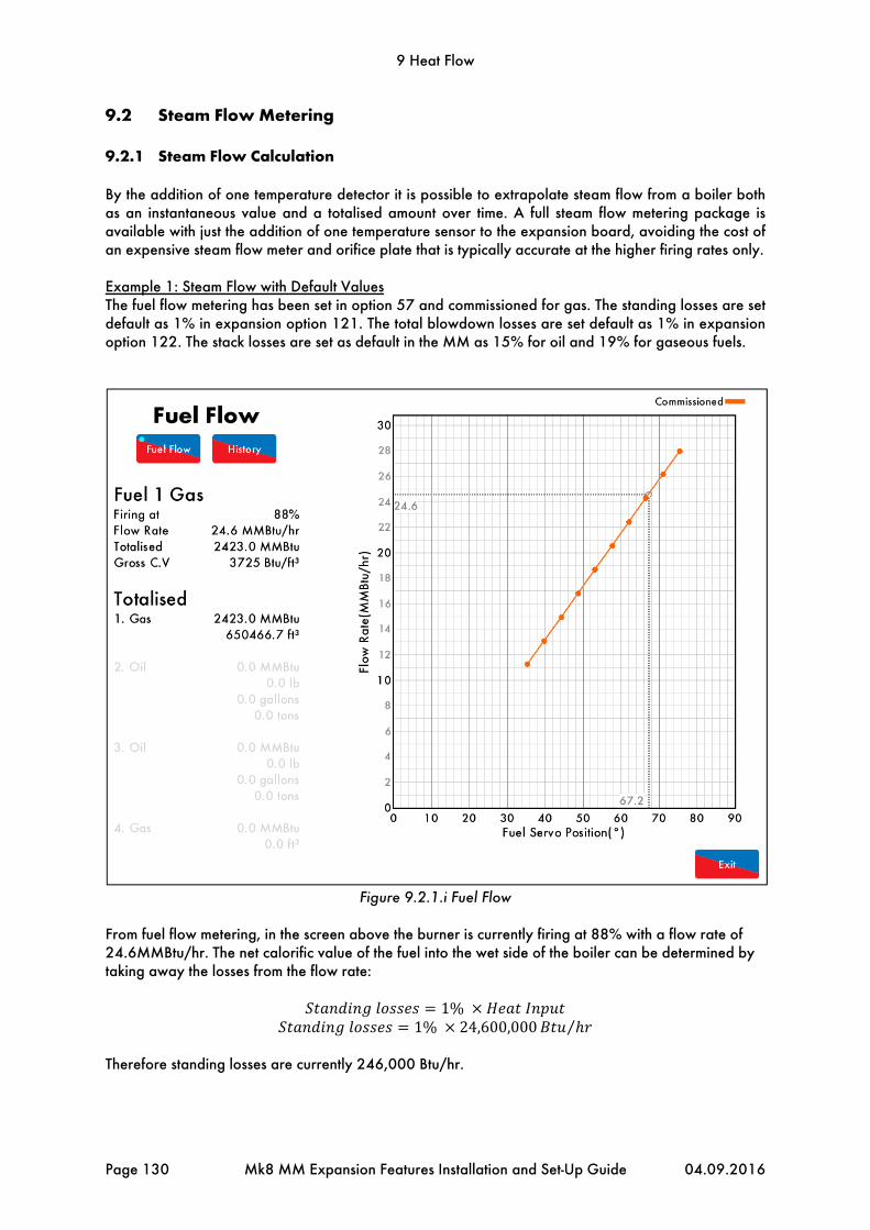
9 Heat Flow
Page 130 Mk8 MM Expansion Features Installation and Set-Up Guide 04.09.2016
9.2 Steam Flow Metering
9.2.1 Steam Flow Calculation
By the addition of one temperature detector it is possible to extrapolate steam flow from a boiler both as an instantaneous value and a totalised amount over time. A full steam flow metering package is available with just the addition of one temperature sensor to the expansion board, avoiding the cost of an expensive steam flow meter and orifice plate that is typically accurate at the higher firing rates only. Example 1: Steam Flow with Default Values The fuel flow metering has been set in option 57 and commissioned for gas. The standing losses are set default as 1% in expansion option 121. The total blowdown losses are set default as 1% in expansion option 122. The stack losses are set as default in the MM as 15% for oil and 19% for gaseous fuels.
Figure 9.2.1.i Fuel Flow
From fuel flow metering, in the screen above the burner is currently firing at 88% with a flow rate of 24.6MMBtu/hr. The net calorific value of the fuel into the wet side of the boiler can be determined by taking away the losses from the flow rate:
1% 1% 24,600,000 ⁄
Therefore standing losses are currently 246,000 Btu/hr.

9 Heat Flow
04.09.2016 Mk8 MM Expansion Features Installation and Set-Up Guide Page 131
19%
19% 24,600,000 ⁄ Therefore stack losses are currently 4,674,000 Btu/hr. Note: If an EGA is optioned, then the stack losses are taken from the EGA data rather than default system values for greater accuracy.
1% 1% 24,600,000 /
Therefore combined blowdown losses are currently 246,000 Btu/hr.
24,600,000 ⁄ 246,000 ⁄ 4,674,000 ⁄ 246,000 ⁄
Therefore the net calorific value of the fuel (wet) is 19,434,000 Btu/hr. The boiler efficiency is determined by:
19,434,000 /24,600,000 /
Therefore the current boiler efficency is 79.0%, which is seen on the Steam Flow Status screen.

9 Heat Flow
Page 132 Mk8 MM Expansion Features Installation and Set-Up Guide 04.09.2016
Figure 9.2.1.i Steam Flow Status
The Steam Flow Status screen shows that the feed water temperature is currently at 180.0OF, with steam at a pressure of 51 PSI and 298.7 OF. Note: Feed water temperature sensors can be used for greater accuracy. The amount of heat needed to change the feed water to steam, is found by the amount of heat needed to raise 1 lb of feed water at 180.0OF to steam at 51 PSI and 298.7 OF. The standard steam tables are built in within the steam flow metering on the MM, and this is then calculated as 1032 Btu/lb. This figure is the latent heat of liquid into steam (gas) plus the sensible heat components. The steam flow rate is shown in lb/hr is determined by:
19,434,000 /
1032 /
Therefore the current steam flow rate is calculated to be 18,831 Btu/lb.

9 Heat Flow
04.09.2016 Mk8 MM Expansion Features Installation and Set-Up Guide Page 133
Example 2: Steam with Deaerator A common practice in steam generation is the use of a “deaerator” to remove the oxygen from the feed water and hence reduce the incidence of oxygen corrosion in the boiler, steam and condensate pipe work. The principle of a deaerator is to mix the make-up water with the condensate return and live steam direct from the boiler in a tank. Flash steam may also be directed back to the tank. The effect is to mechanically “scrub” the oxygen from the feed water and also to preheat it before it is pumped to the boiler. In the system as set out above it is no longer valid to measure the temperature of the feed water just before it enters the boiler as the inlet temperature for the “steam meter” calculation. This water has already been preheated by steam from the boiler and therefore this additional energy should not be taken into the software calculation. The solution is to treat the boiler and deaerator as one system. The energy into the system is supplied by the burner and the inlet temperature is the “weighted average” of the condensate return temperature and makeup water temperature. The outlet steam temperature is measured by a temperature sensor in exactly the same way as in a system without a deaerator. 1: First the percentage “Make up“ in the “Feed water” must be calculated. Where %Mu = % Cold make up water
V1 = Volume flow rate of condensate return water V2 = Volume flow rate of cold make up water
%Mu 100xV2V2 V1
Example: 1 Steam boiler with a volume of condensate return at 40 GPM and make up water at 8 GPM
Makeup% 100x88 40
16.7%
To calculate the second part to establish the “Weighted Average Temperature” the following equation is used. Where Tave = Weighted Average temperature
T3 = Temperature of condensate T1 = Temperature of make up water %Mu = Percentage of make up water
Tave T3 %Mux T1A T1
100
Steam boiler with condensate return temperature of 176°F and a make up water temperature of 41°F. From the above example (1) the make up percentage is 16.7%
WeightedAverage 176 16.7x 176– 41
100 153.4°F
To implement the above control form the following calculations have been imbedded in the revised software to obtain the “Weighted Average Temperature” (T ave).

9 Heat Flow
Page 134 Mk8 MM Expansion Features Installation and Set-Up Guide 04.09.2016
9.2.2 Steam Flow
Expansion option 120 set to 2

9 Heat Flow
04.09.2016 Mk8 MM Expansion Features Installation and Set-Up Guide Page 135
9.2.3 Steam Flow with Economiser
Expansion option 120 set to 3.

9 Heat Flow
Page 136 Mk8 MM Expansion Features Installation and Set-Up Guide 04.09.2016
9.2.4 Steam Flow with Deaerator
Expansion option 120 set to 4.

9 Heat Flow
04.09.2016 Mk8 MM Expansion Features Installation and Set-Up Guide Page 137
9.2.5 Steam Flow with Deaerator and Feed Sensor
Expansion option 120 set to 6.

9 Heat Flow
Page 138 Mk8 MM Expansion Features Installation and Set-Up Guide 04.09.2016
9.3 Hot Water Flow Metering
Heat Flow Metering is simply measuring the amount of heat being transferred to the water by a hot water boiler. If we know the stack losses and the standing losses of the boiler at any moment then whatever energy is left over must be going into the water. From the E.G.A. stack losses = 100 – combustion efficiency Radiation losses are specific to the boiler, 1% radiation losses are typical for a packaged boiler operating at maximum continuous rating. The loss is constant regardless of boiler output so at 50% firing rate it would be 2% of the energy input. The total heat in at any time is given by the heat flow metering so we can calculate the instantaneous heat going into water. By integrating these values we can get a totalised value.
9.3.1 Hot Water Flow Calculation
Efficiency% 100% StacklossRadiationLosses 100
FiringRate
UsefulHeatintoWater TotalHeatEfficiency
100
VolumeFlowinlbs/hr UsefulheatMBTU/Hr
SPHtBTU/lb/°F FlowTemp–ReturnTemp
VolumeFlowincuftHrVolumeFlowin lbs hr⁄
DensityofWateratReturnTemperature
Since1cuftHr 0.124676USG. P. M.
VolumeFlowinUSG. P.M. VolumeFlowincuftHr 0.124676
Example A boiler firing at 75% has an input of 20,472,840 BTU/Hr (6MW). The temperature of the flow (MM Temperature detector) out is 185°F and the temperature of the return T1 is 167°F. The combustion efficiency is 82% (Mk7), Radiation losses are 1% at maximum continuous rating. Description Imperial units Metric Units Firing rate 75% 75% Input 20.47 MMBTU/HR 6MW Return Temperature 167°F 75°C Flow Temperature 185°F 85°C Sp Ht water 1.0 BTU/lb/°F 4.18KJ/KG/°C Density Water 60.68lb/cuft @176°F 972 kg M³ @80°C Combustion Efficiency 82% 82%
Efficiency% 100% 18%1% 10075%
80.67%
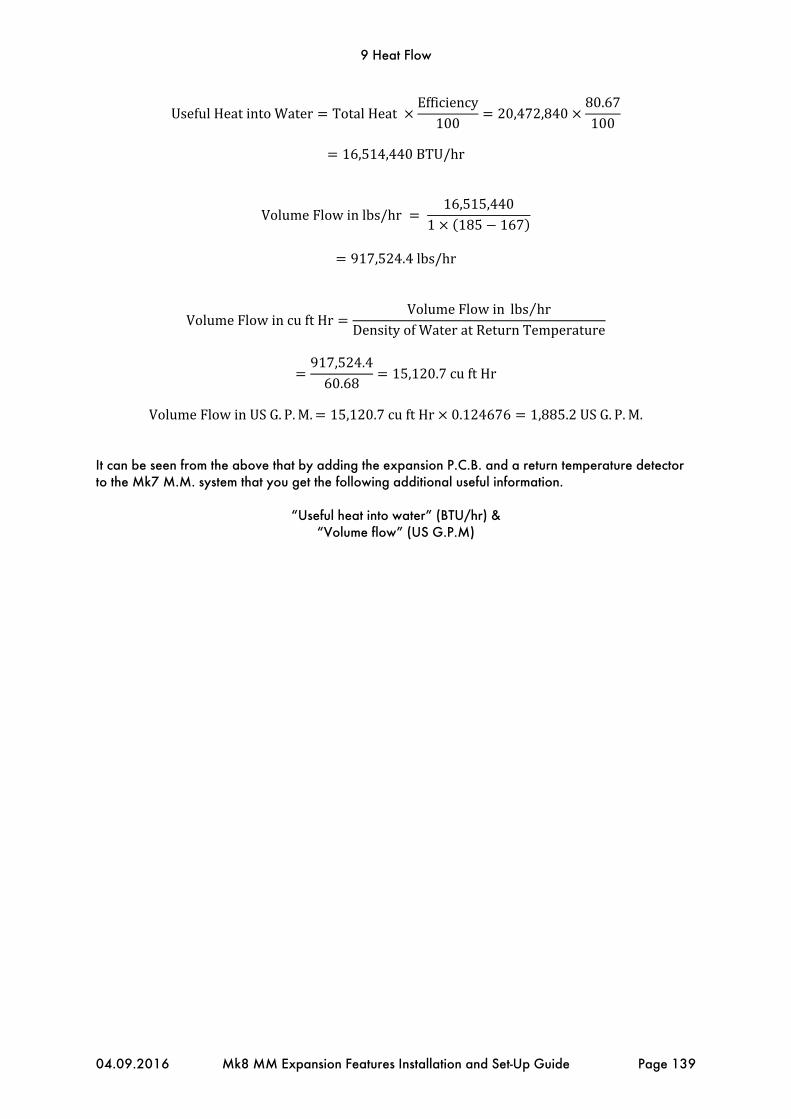
9 Heat Flow
04.09.2016 Mk8 MM Expansion Features Installation and Set-Up Guide Page 139
UsefulHeatintoWater TotalHeatEfficiency
10020,472,840
80.67100
16,514,440BTU/hr
VolumeFlowinlbs/hr 16,515,440
1 185 167
917,524.4lbs/hr
VolumeFlowincuftHrVolumeFlowin lbs hr⁄
DensityofWateratReturnTemperature
917,524.460.68
15,120.7cuftHr
VolumeFlowinUSG. P.M. 15,120.7cuftHr 0.124676 1,885.2USG. P. M.
It can be seen from the above that by adding the expansion P.C.B. and a return temperature detector to the Mk7 M.M. system that you get the following additional useful information.
“Useful heat into water” (BTU/hr) & “Volume flow” (US G.P.M)

9 Heat Flow
Page 140 Mk8 MM Expansion Features Installation and Set-Up Guide 04.09.2016
9.3.2 Hot Water Flow
Expansion option 120 set to 8

9 Heat Flow
04.09.2016 Mk8 MM Expansion Features Installation and Set-Up Guide Page 141
9.3.3 Hot Water Flow with Economiser
Expansion option 120 set to 9.
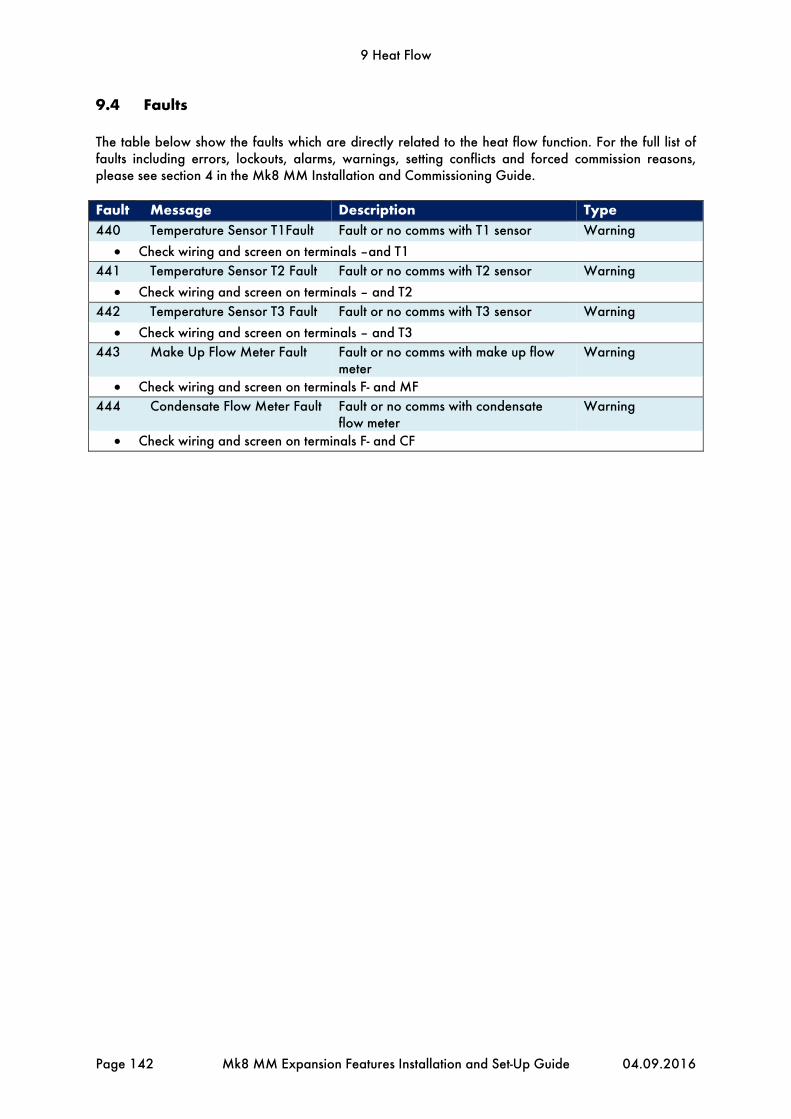
9 Heat Flow
Page 142 Mk8 MM Expansion Features Installation and Set-Up Guide 04.09.2016
9.4 Faults
The table below show the faults which are directly related to the heat flow function. For the full list of faults including errors, lockouts, alarms, warnings, setting conflicts and forced commission reasons, please see section 4 in the Mk8 MM Installation and Commissioning Guide. Fault Message Description Type 440 Temperature Sensor T1Fault Fault or no comms with T1 sensor Warning
Check wiring and screen on terminals –and T1
441 Temperature Sensor T2 Fault Fault or no comms with T2 sensor Warning
Check wiring and screen on terminals – and T2
442 Temperature Sensor T3 Fault Fault or no comms with T3 sensor Warning
Check wiring and screen on terminals – and T3
443 Make Up Flow Meter Fault Fault or no comms with make up flow meter
Warning
Check wiring and screen on terminals F- and MF
444 Condensate Flow Meter Fault Fault or no comms with condensate flow meter
Warning
Check wiring and screen on terminals F- and CF

10 Fully Metered Combustion Control
04.09.2016 Mk8 MM Expansion Features Installation and Set-Up Guide Page 143
10 FULLY METERED COMBUSTION CONTROL
10.1 Overview
10.1.1 Introduction
The fuel-air mixture will determine the combustion performance; poor mixing of the fuel and air will reduce the burner’s combustion performance, and in turn, decrease the combustion efficiency. Too fuel rich a fuel-air ratio will result in incomplete combustion, leaving unburnt fuel in the combustion products. Unburnt fuel will cause soot build-up or release harmful CO emissions. In the boiler room, incomplete combustion wastes the fuel, so more fuel is required to meet the load demand, causing a high fuel bill. On the contrast, too much air in the combustion process will waste the heat generated by the fuel burning to heat the excess air; again, the fuel bills will increase. The fully metered system is used in applications where it is not possible to measure the exhaust gases in the stack, or if the firing rate is critical to system and controlled remotely. 10.1.2 Importance of Excess Air
In ideal stoichiometric combustion, all the fuel is mixed with the exact amount of air for it to be converted fully to CO2, H2O (N2), releasing heat from the reaction. In the practical world where ideal and laboratory conditions do not always exist, it is necessary to add more air than that required in stoichiometric combustion to ensure complete combustion. The equivalence ratio of the combustion is:
//
Or alternatively, if the volume is known:
//
Where n is the number of moles of gas, proportional to the corrected volume. The excess air is the extra amount of air supplied over the amount of air required for complete combustion, and can be determined from the equivalence ratio:
1
1
100%
This can be converted to the wet exhaust gas O2 by:
21%
11
Higher excess air levels will give higher O2 values in the exhaust gases. The optimum excess air will depend on the fuel type, the combustion chamber design and the burner turndown. High performance burners will operate 3% O2 (dry) when firing on natural gas, which is equivalent to 15% excess air going into the burner, whilst producing 0ppm of CO. The stoichiometric data in the lookup tables of the software is gives the excess air based on the fuel and air flow rates, and the calorific value of the fuel.

10 Fully Metered Combustion Control
Page 144 Mk8 MM Expansion Features Installation and Set-Up Guide 04.09.2016
10.2 Fully Metered Combustion Control Operation
10.2.1 Philosophy
The fully metered system will add a layer on top of the standard commission map, with the aim of maintaining the fuel-air ratio for each firing rate. The system can either directly measure mass flow or use corrected volume flows to maintain this ratio. The Mk8 MM continuously measures the fuel and air flows to compensate for any variations from stored values, in an effort to maintain the commissioned burner efficiency. To compensate for changes the MM will trim the air damper position to try to maintain the commissioned excess air. In addition the MM will move the fuel valve, to try to achieve the firing rate required to maintain the commissioned heat input. The fully metered combustion control works with the commissioned fuel valve and air damper positions, storing the mass or volume flow of the fuel and air at each point. The flow data is recorded using two 4-20mA inputs, which can be the data from a mass flow meter or calculated from volume flow meter. When using a volume flow meter the fuel density is used to calculate and display a mass flow using either default values or temperature and Autoflame pressure sensors. If variations occur from the commissioned fuel or air flow, the MM will trim servomotors up to an option limited percentage of their commissioned positions at that time. Unlike other systems, the Autoflame fully metered operation is based on the commissioned fuel-air curve, so combustion deviations are compensated for faster than those systems without a base firing curve. Should any faults occur with the meters, the control can be optioned to revert to the default fuel-air curve to allow the burner to continue to run. As the fuel valve moves to reach the commissioning firing rate, based on the measured mass flow rate, the air damper will also adjust to achieve the commissioned excess air, due to proportional change required in air flow. 10.2.2 Firing Rate
When measuring the mass flow, the control process will aim to maintain the same fuel-air ratio as the commissioned fuel flow and air flow ratio. The burner’s firing rate can be controlled by the Autoflame internal PID, external modulation, hand mode, DTI firing rate or Modbus firing rate. Without fully metered combustion control, the MM would map the fuel valve angle through the fuel flow curve, whereas with this control, the fully metered system firing rate is proportional to the mass flow. The firing rate is then determined by:
100%
The maximum mass fuel flow rate is the fuel flow rate recorded at the high fire position during commissioning. From this, once the burner commission is complete, the fuel flow curve is mapped out automatically based on the formula above. This means that if the flow meters fail, the MM can revert back to the default behaviour and use the pre-stored fuel flow curve. Also, if after commission the high fire position was moved in single point change, the MM will update the fuel flow curve automatically.

10 Fully Metered Combustion Control
04.09.2016 Mk8 MM Expansion Features Installation and Set-Up Guide Page 145
10.2.3 Control Process
The air servomotor will trim to maintain the commissioned fuel-air ratio. The fuel servomotor will trim to maintain the commissioned firing rate. Both of these control function operate independently if fully metered combustion control is enabled.

10 Fully Metered Combustion Control
Page 146 Mk8 MM Expansion Features Installation and Set-Up Guide 04.09.2016
10.2.4 Mass Flow Meters
When using mass flow meters the fuel and air rates are displayed on the MM, these are based on the 4-20mA input signals from the mass flow meters. The control process will aim to maintain the same fuel-air ratio as those set during the commissioning process. If the fully metered system is set with a fuel mass flow meter, then the fuel temperature and pressure sensors are not required for the fully metered control; however the pressure sensor can still be used for VPS and high/low pressure limits. If an air mass flow meter is used, then again the air temperature and pressure sensors are not required; however the air pressure sensor can still be used for air pressure checking during burner start-up e.g. purge air pressure proving. The calorific value of the fuel is used to calculate the excess air, so this must be entered accurately. 10.2.5 Volume Flow Meters
When using volume flow meters for the fuel and mass flow rate information, corrections need to be applied to derive the mass flow rate. The MM calculates the mass flows using the fuel density and calorific value; these must be set accurately for the fuel being metered. If a differential pressure sensor is being used the system can be optioned to perform square root extraction on the input, thus saving an external converter. Based on the ideal gas flow, assuming that the humidity and the specific gas constant do not vary, the mass flow rate is related to the volume flow rate by the following equation:
∝
∝
This formula is used internally calculated in the MM to provide a mass flow rate, this is calculated individually for both gas and air in the MM using the following assumptions: Variable Action Ambient air pressure Average ambient pressure, set in expansion option 153 Differential air pressure Air pressure correction not used (assumed 20mbar) Air temperature Air temperature correction not used (assumed 20OC) Gas pressure Gas pressure correction not used (assumed 100mbar) Gas temperature Gas temperature correction not used (assumed 5OC) If additional Autoflame temperature and pressure sensors are used on the either or both the gas and air then the calculated mass flow rate displayed will be more accurate. In the event of a sensor failure, the temperature/pressure value of the failed sensor that was stored at commissioning of value is used to calculate the displayed mass flow rate allowing the system to continue to run. If the gas and air pressure sensors are used also used for the VPS, gas pressure limits or air sensors limits, then the burner will lockout in the event of a sensor failure.
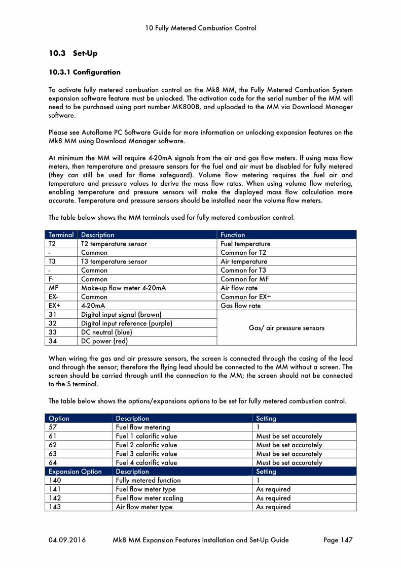
10 Fully Metered Combustion Control
04.09.2016 Mk8 MM Expansion Features Installation and Set-Up Guide Page 147
10.3 Set-Up
10.3.1 Configuration
To activate fully metered combustion control on the Mk8 MM, the Fully Metered Combustion System expansion software feature must be unlocked. The activation code for the serial number of the MM will need to be purchased using part number MK8008, and uploaded to the MM via Download Manager software. Please see Autoflame PC Software Guide for more information on unlocking expansion features on the Mk8 MM using Download Manager software. At minimum the MM will require 4-20mA signals from the air and gas flow meters. If using mass flow meters, then temperature and pressure sensors for the fuel and air must be disabled for fully metered (they can still be used for flame safeguard). Volume flow metering requires the fuel air and temperature and pressure values to derive the mass flow rates. When using volume flow metering, enabling temperature and pressure sensors will make the displayed mass flow calculation more accurate. Temperature and pressure sensors should be installed near the volume flow meters. The table below shows the MM terminals used for fully metered combustion control. Terminal Description Function T2 T2 temperature sensor Fuel temperature - Common Common for T2 T3 T3 temperature sensor Air temperature - Common Common for T3 F- Common Common for MF MF Make-up flow meter 4-20mA Air flow rate EX- Common Common for EX+ EX+ 4-20mA Gas flow rate 31 Digital input signal (brown)
Gas/ air pressure sensors 32 Digital input reference (purple) 33 DC neutral (blue) 34 DC power (red) When wiring the gas and air pressure sensors, the screen is connected through the casing of the lead and through the sensor; therefore the flying lead should be connected to the MM without a screen. The screen should be carried through until the connection to the MM; the screen should not be connected to the S terminal. The table below shows the options/expansions options to be set for fully metered combustion control. Option Description Setting 57 Fuel flow metering 1 61 Fuel 1 calorific value Must be set accurately 62 Fuel 2 calorific value Must be set accurately 63 Fuel 3 calorific value Must be set accurately 64 Fuel 4 calorific value Must be set accurately Expansion Option Description Setting 140 Fully metered function 1 141 Fuel flow meter type As required 142 Fuel flow meter scaling As required 143 Air flow meter type As required

10 Fully Metered Combustion Control
Page 148 Mk8 MM Expansion Features Installation and Set-Up Guide 04.09.2016
144 Air flow meter scaling As required 145 Fuel temperature sensor enable Optional 146 Air temperature sensor enable Optional 147 Fuel pressure sensor enable Optional 148 Air pressure sensor enable Optional 149 Maximum fuel channel compensation As required 150 Maximum air channel compensation As required 151 Action on air adjustment failure As required 152 Action on flow meter failure As required 153 Default ambient air pressure As required 154 Fuel 1 density Required for volume flow meter 155 Fuel 2 density Required for volume flow meter 156 Fuel 3 density Required for volume flow meter 157 Fuel 4 density Required for volume flow meter
The current firing rate can be fed back to an external system via a 4-20mA output signal on terminals 16, 17 and 18.
10.3.2 Limitations
When using a volume flow meter, the mass flow rate is calculated using the volume flow rate and either default pressure and temperature values, or the measured pressure and temperature values. The MM’s fully metered combustion control is capable of controlling the most common hydrocarbon fuels including methane, ethanol, ethane, butane, pentane, acetylene and 1-proponal. For FGR, oxy fuels, hydrogen and special fuels, please contact Autoflame prior to use; The fully metered combustion control will not work on oil combustion curves. If fully metered combustion control is used, then neither an external 4-20mA sensor for auxiliary water level control nor external fuel flow metering using 4-20mA input can be used. When using the fully metered system, the fuel flow metering is automatically calculated from the flow rate. If an EGA is optioned, a conflict will occur if the 3-parameter trim is activated. The gas/air pressure sensor recommission feature is not available when using volume flow meters, if these pressure sensors need to be recommissioned; a full recommission of the burner is required. This is due to the pressures needing to be stored at the same time as the required volume flow. Economiser or deaerator options for steam/heat flow metering cannot be used if the temperature sensors or make-up flow meter inputs are being used for volume flow metering. The IO module can be used instead for deaerator. During running the system can adjust the channel 2 air servomotor from the commissioned closed and open positions to bring the combustion to the commissioned fuel-air ratio, as the fuel servomotor moves. However, the rest of the channels can only be moved from the low fire and high position, and not outside of this range. This means that if the fuel servomotor is at the commissioned high fire position, it cannot move further. The firing rate is limited to less than 100% and if it is critical to the system operation, then the actual firing rate should be monitored. The calorific value must be entered corrected to the 1013mbar and 15OC, see options 61 to 64.

10 Fully Metered Combustion Control
04.09.2016 Mk8 MM Expansion Features Installation and Set-Up Guide Page 149
10.3.3 Commissioning
Important Note: Prior to commissioning, the fuel and air servomotors must be calibrated to ensure that the position of the valves and damper correspond to the potentiometer feedback signal as displayed on the MM. When the valve is fully closed, the MM should display zero degrees. If it does not, please adjust the servomotor potentiometer. The commissioning procedure as described must be strictly adhered to. Anybody commissioning an MM must be trained in operating combustion equipment safely. The Autoflame products must only be installed, set up, commissioned and adjusted by an Autoflame certified technical engineer. The fundamental idea of the system is to set a fuel valve position and then set a corresponding air damper position. Care must be taken when adjusting the fuel and air positions so as not to create any unstable or hazardous combustion conditions, e.g. moving the fuel valve to the open position without increasing the air damper position. Improper use may result in property damage, serious physical injury or death. The equivalence ratio and excess air provided on the MM are calculated displays based on setup and inputs from external sources. The exhaust gases should be monitored using a combustion analyser at all times during commissioning and for any changes to the combustion curve. WARNING: COMMISSIONING OR BURNER START-UP MUST ONLY BE
CARRIED OUT BY A FACTORY TRAINED TECHNICIAN.

10 Fully Metered Combustion Control
Page 150 Mk8 MM Expansion Features Installation and Set-Up Guide 04.09.2016
Figure 10.3.3.i Set HIGH Position
For the installation and pre-commissioning checks, please refer to sections 3.2 and 3.3 in the Mk8 MM Installation and Commissioning Guide. The same commissioning procedure for the fully metered combustion control system as the standard system’s servomotors and VSDs. The difference is that the commissioning engineer can see on the screen the excess air going into the combustion process and can set the servomotors and VSDs accordingly. The screen above shows the HIGH position for the servomotors and VSDs being set.

10 Fully Metered Combustion Control
04.09.2016 Mk8 MM Expansion Features Installation and Set-Up Guide Page 151
Figure 10.3.3.ii Fully Metered Commission
Pressing on the fully metered tab in the commission screen can show the following, based on how the system has been set:
Equivalence ratio Fuel flow rate (mass, volume) Fuel temperature Fuel pressure Excess air Air flow rate (mass, volume) Air temperature Air pressure
The table will populate mass flow rates of the fuel and air, and the excess air, for each commissioned point. The commissioned points can be changed/added/removed in single point change as normal, please see section 3.7 in the Mk8 Installation and Commissioning Guide for more information. Note, if the sensors or the flow meters have a fault, then single point change feature is disabled.

10 Fully Metered Combustion Control
Page 152 Mk8 MM Expansion Features Installation and Set-Up Guide 04.09.2016
10.3.3.i Home Screen – Excess Air
The home screen will display the current excess air going into the combustion process. Pressing on the servomotors will show the fuel-air screens with the following information available:
Current fuel and air mass flow rates Current fuel and air volume flow rates Current fuel and air temperatures Current fuel and air pressures Current fuel and air correction % to maintain the fuel-air ratio at that firing rate Current equivalence ratio Current excess air Commissioned excess air

10 Fully Metered Combustion Control
04.09.2016 Mk8 MM Expansion Features Installation and Set-Up Guide Page 153
10.4 Faults
The table below show the faults which are directly related to the fully metered combustion control function. For the full list of faults including errors, lockouts, alarms, warnings, setting conflicts and forced commission reasons, please see section 4 in the Mk8 MM Installation and Commissioning Guide. Fault Message Description Type 550 Fuel Flow Meter Fault Less than 3mA signal received Alarm/Warning –
exp option 152 Check wiring and screen on terminal MF and F- Warning if expansion option 152 is set to 1 and MM will then use the commissioned value
without any fuel or air servomotor adjustment 551 Air Flow Meter Fault Less than 3mA signal received Alarm/Warning –
exp option 152 Check wiring and screen on terminal EX+ and EX- Warning if expansion option 152 is set to 1 and MM will then use the commissioned value
without any fuel or air servomotor adjustment 552 Fuel Temperature Sensor
Fault (T2) Fault or no comms with T2 sensor Warning
Check wiring and screen on terminals – and T2 Warning – MM uses commissioned temperature
553 Air Temperature Sensor Fault (T3)
Fault or no comms with T3 sensor Warning
Check wiring and screen on terminals – and T3 Warning – MM uses commissioned temperature
554 Fuel Pressure Sensor Fault Fault or no comms with fuel pressure sensor
Warning/ Lockout – option 125 (fuel)
Check wiring and screen on terminals 31 – 34 If warning generated, MM will use commissioned value Lockout if option 125/126/126/128 is set for VPS or high/low pressure limits in flame
safeguard 555 Air Pressure Sensor Fault Fault or no comms with air pressure
sensor Warning/Lockout – option 148
Check wiring and screen on terminals 31 – 34 Lockout if option 148 is set for air pressure sensor in flame safeguard
560 Fully Metered Air Adjustment Failure
Air adjustment has reached limit and fuel-air ratio still not met
Alarm/Warning – exp option 151
Check for changes affecting combustion including fuel/air pressure, temperature etc. Warning if expansion option 151 is set to 1 Warning and air adjustment is disabled if expansion option 151 is set to 2


Notes


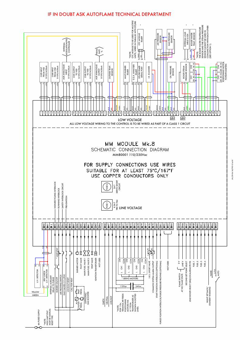


Autoflame Engineering Ltd Unit1-2 Concorde Business Centre
Airport Industrial Estate, Wireless Road Biggin Hill, Kent TN16 3YN
United Kingdom +44 (0) 845 872 2000 www.autoflame.com