Embed Size (px)
Citation preview

MK2 Engine Sound Simulator (Combo) © Technobots 2014
1
MK2 ENGINE SOUND
SIMULATOR Instructions for: #3803-233 COMBO
This engine sound simulator is principally intended for radio controlled model boats but may also find application in trucks, tanks, cars, rock-crawlers and even aircraft.
FEATURES
The MK2 Engine Sound Simulator is packaged in a small footprint, low
profile, laser cut acrylic case which allows all wiring connections and
adjustments to be made without the need to first remove the case.
Functional features of the Combo unit are as follows:-
9 different engine „voices‟ to choose from
automatic start/stop
start-up and run-down sounds („petrol‟ & „diesel‟ only)
simple user adjustment of o tickover o top speed o idling timeout period o engine „voice‟ o cylinder count o neutral o span
„demo‟ mode
bi-colour LED indicates neutral and run conditions
option for remote set-up
Of the Combo MK2‟s nine engine „voices‟, eight represent different types of „petrol‟ / „diesel‟ engines whilst the remaining one is „steam‟.
The user interface allows the user to interactively adjust the engine type, its number of cylinders, its tickover, top speed and idling time-

MK2 Engine Sound Simulator (Combo) © Technobots 2014
2
out duration via a simple system utilising a pushbutton on the unit in conjunction with the transmitter‟s throttle joystick.
Users may also set the unit to match both the neutral and span parameters of the transmitter joystick anywhere within its 1-2mS range thereby accommodating forward only systems and pistol type controllers with a 70/30 forward/reverse range.
A further feature is the „Demo‟ mode which is of use in static displays at exhibitions. This allows the model‟s sound capability to be demonstrated without running the motor(s) - a neutral (stop) signal is sent to the ESC during this mode.
A red/green bi-colour LED serves to indicate both the neutral and the run conditions, thus always showing that the unit is powered. In addition, the LED pulses in sympathy with the engine speed when the latter is running.
Provision has been made for the user to (optionally) install a remote pushbutton in some convenient location in the model such that all adjustments can be made in the field without having to open up the model. Alternatively the remote push button could be replaced by a (relay type) RC switch allowing total set-up capability from the user‟s transmitter.
OVERVIEW
The sound unit picks up its speed demand from the r/c throttle signal of
the model and produces an engine sound that varies smoothly and
proportionally with the throttle setting demand in both forward and
reverse. With the throttle closed, the engine has an idling time-out period
followed by a „run-down‟ (stopping) sound. Opening the throttle again
causes the engine to re-start following a short „cranking‟ sound. The
start-up and run-down sounds are inappropriate for the steam option and
are therefore omitted.
The unit is designed to be used with any digital proportional PPM radio
control systems, including PCM that utilises the industry standard 1-2mS
servo signal. The unit is easily installed by removing the Electronic
Speed Controller (ESC) lead from your receiver and plugging in the
„THR‟ lead from the sound unit in its place. The ESC lead then plugs into
the sound unit‟s „ESC‟ port. The unit's electronics takes its power from
MK2 Engine Sound Simulator (Combo) © Technobots 2014
3
the receiver, but the loudspeaker derives its power from either the
model's main propulsion battery or a separate battery pack. Connections
for the speaker power and the loudspeaker itself are made using screw
terminal blocks.
Whilst a synthesized engine sound can never compete with recordings
of the real thing, this unit captures the 'spirit' of the various engine
sounds.
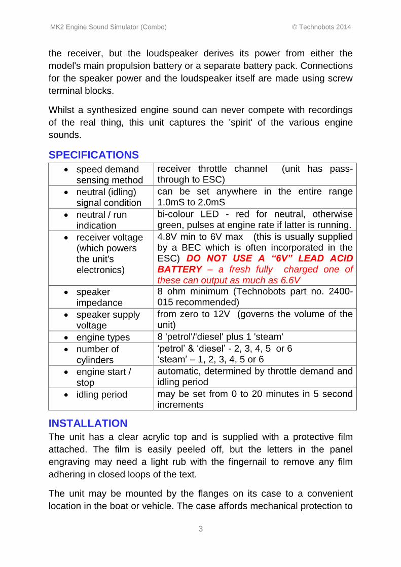
SPECIFICATIONS
speed demand sensing method
receiver throttle channel (unit has pass-through to ESC)
neutral (idling) signal condition
can be set anywhere in the entire range 1.0mS to 2.0mS
neutral / run indication
bi-colour LED - red for neutral, otherwise green, pulses at engine rate if latter is running.
receiver voltage (which powers the unit's electronics)
4.8V min to 6V max (this is usually supplied by a BEC which is often incorporated in the ESC) DO NOT USE A “6V” LEAD ACID BATTERY – a fresh fully charged one of these can output as much as 6.6V
speaker impedance
8 ohm minimum (Technobots part no. 2400-015 recommended)
speaker supply voltage
from zero to 12V (governs the volume of the unit)
engine types 8 'petrol'/'diesel' plus 1 'steam'
number of cylinders
„petrol‟ & „diesel‟ - 2, 3, 4, 5 or 6 „steam‟ – 1, 2, 3, 4, 5 or 6
engine start / stop
automatic, determined by throttle demand and idling period
idling period may be set from 0 to 20 minutes in 5 second increments
INSTALLATION
The unit has a clear acrylic top and is supplied with a protective film
attached. The film is easily peeled off, but the letters in the panel
engraving may need a light rub with the fingernail to remove any film
adhering in closed loops of the text.
The unit may be mounted by the flanges on its case to a convenient
location in the boat or vehicle. The case affords mechanical protection to

MK2 Engine Sound Simulator (Combo) © Technobots 2014
4
the electronic circuitry and renders it “splash resistant” but certainly not
“waterproof”, so in marine installations it should be mounted accordingly.
Acrylic is brittle, so do not over-tighten the fixing screws.
Figures 1 and 2 below show the connector designations.
The engraving on the lid of the case shows the connector functions and their polarities, which in this image are shown highlighted in red for clarity.
Figure 1 – View of the unit lid showing connector legends
Wiring to the loudspeaker and the speaker power supply (BATT – and +) is made into the terminal block on the circuit board via the slot in the end of the case. A slot in the lid allows screwdriver access to the terminal block to tighten the screws.
Figure 2 – View of the unit showing access to the terminal blocks
Ideally the unit should be mounted close enough to the ESC for the
latter's signal input lead to reach the ESC port on the unit, but failing that
a servo extension lead can be used (Technobots part #3601-003). A
male/male connector lead (JR type - brown, red, orange) is supplied to
connect the receiver‟s throttle channel to the sound unit‟s THR port.
Both these leads are inserted side by side through a slot in the top of the
case onto the three pin headers on the circuit board Be sure to mate the
connectors correctly, guided by the +/- legends on the case lid and the
table in the wiring diagram (Fig 4) below which shows equivalence of the
JR, Futaba and Hitec industry standard colour schemes.
You must connect up the unit in this manner rather than using a „Y‟ lead
from the receiver to the sound unit and ESC, as the unit outputs a
neutral (stop) signal to the ESC whilst the various set-up routines are

MK2 Engine Sound Simulator (Combo) © Technobots 2014
5
being executed and also during the „Demo‟ mode. For this reason the
throttle and ESC ports are NOT interchangeable.
If the user elects to fit a remote pushbutton, then this should be plugged into the two pin header (marked „P/B‟) through the same slot in the case. For those users, a matching lead is available for purchase from Technobots (#3601-030). Size and fitting constraints dictated by the model mean that the pushbutton is best chosen by the user and must be a momentary action ‘press to make’ type. Technobots carry a range of suitable pushbuttons, #1613-061 being a good example.
Users could also consider replacing the remote push button by a relay
type RC switch in order to allow total set-up capability from their
transmitter. Again Technobots have a range of suitable types – see the
“Radio Controlled (RC) Relays” section under the “Interfaces” tab. Note
that the digital output types shown there are NOT compatible.
WIRING
The wiring diagram (figure 3 below) illustrates the typical interconnection
of the major components of a basic RC model, prior to installing the
sound unit. The main battery usually ranges between 6 to 12V and in
the example shown the Electronic Speed Controller (ESC) has a built-in
Battery Eliminator Circuit (BEC) which drops the receiver and servo
voltage down to 5V. In the event that the ESC does not have an integral
BEC then sometimes a separate receiver battery pack is used and is
plugged into either a spare channel, or a dedicated battery slot on the
receiver. Receiver battery packs are typically 4 AA cells, either 1.2V
NiMh rechargeables or 1.5V primary cells.
Figure 3 – Typical wiring of an R/C model

MK2 Engine Sound Simulator (Combo) © Technobots 2014
6
As will be seen from figure 4 below, the sound unit is simply interposed
between the receiver and the ESC, and takes its speaker power from the
main battery.
Figure 4 – Wiring up the sound unit (case removed for clarity)
Note the colours and orientation of the (JR standard) cables connecting
receiver and ESC to the sound unit.
The battery supply to the sound unit and the speaker currents are very modest and thin multi-strand flexible cable of 1amp rating (or higher) can be used (Technobots 7/0.2mm Equipment Wire)
SPEAKER POWER SUPPLY
As the installation diagram shows this is usually taken from the main
propulsion battery of the model. Correct polarity MUST be observed -
battery positive to the “+”, and battery negative to the “-“. Connection of
these leads alone will NOT power the unit, and equally without these
leads being connected there will be no sound output from the unit.

MK2 Engine Sound Simulator (Combo) © Technobots 2014
7
As the speaker signal is digital in nature, for simplicity, cost and
efficiency the speaker is switched directly to its battery supply. This
results in the output volume not being adjustable. But to a very large
degree the quality and volume of sound produced will depend on the
speaker itself and the way it is mounted in the model. If for example
using a 6V propulsion battery the resultant sound is too quiet, or if on
12V it is too loud then an auxiliary battery or batteries of higher or lower
overall voltage may be used to achieve the volume level required (12V
maximum limit applies). A pack of AA cells is quite adequate for this
purpose, with the benefit that the number of cells may be easily
adjusted.
MOUNTING OF THE LOUDSPEAKER
Inevitably the size and construction of the model may preclude the
recommended speaker being used and if in addition its installation is
less than ideal, then both the volume and the quality of the sound will be
compromised. If in any doubt as to the unit's capabilities, try connecting
it to a music-centre loudspeaker and hear the result. Your model
sounding anything less rewarding than this represents the magnitude of
your personal battle to defy the laws of acoustics!
Speakers are ideally mounted on a baffle – this is usually a piece of
wood whose width is about twice the diameter of the cone with a hole in
it about the size of the cone (determined by the speaker mounting
arrangement). The purpose of the baffle is to prevent the anti-phase
sound waves from the rear of the cone 'leaking' round to cancel out the
in-phase sound waves from the front. Hi-fi speaker cabinets are
generally sealed to achieve this. The hull of a boat makes an excellent
substitute if the speaker can be mounted beneath the cabin using the
entire deck as a baffle and the sound can escape through open
portholes, windows, doors or ventilation grilles in the superstructure.
If you can't achieve that sort of set-up you can try the recommended
Technobots 10W speaker facing upwards with a 50mm long, thick
cardboard tube whose 75mm internal diameter is a snug fit over the
inboard rigid rim surround of the speaker. The wall thickness of the tube
is about 4/5mm - being the inner former of a roll of heavy duty 50mm
black pvc tape like you find in pound shops. That is stage one and
modifies the sound interestingly - then try the palm of your hand over the
MK2 Engine Sound Simulator (Combo) © Technobots 2014
8
end of the tube – and if you like the result then use some of the black
tape to seal it! Other users report good results from this sort of set-up
with various lengths of sealed stout tube with a short stub opening at the
tube top of maybe 10 to 20mm dia and about 20mm long.
If you make the sound sealing box too small the speaker will struggle to
compress the air in it (the cone displacement must make a large
percentage volumetric change) and the volume and sound quality will
suffer.
The steam unit is the least demanding with respect to both the speaker
and its mounting considerations.
UNIT FAMILIARISATION
It is assumed that the unit has been correctly connected up following the
installation procedure above and the model is restrained on a stand to
allow the propeller(s), wheels or tracks to run free. First set the throttle
joystick to neutral and then switch on the transmitter. Now power the
model and the red LED on the unit should be showing a „solid‟ red,
signifying the engine is stopped and the throttle channel is in the 'neutral'
condition. Advance the throttle and the speaker should issue a short
cranking sound (steam excepted) and the 'engine' should start and
smoothly run up to full speed as the throttle is opened fully, the LED now
flickering green in sympathy with the engine rate. With the joystick
returned to the central position the engine should return to idling speed
and the LED should revert to flickering red. After a user defined period of
idling in neutral the engine will run down to a stop and the LED will then
show a „solid‟ red. (manufacturer‟s default idling period set to 20 secs)
The LED indication for neutral (and the corresponding tickover speed)
may not line up with the existing „neutral‟ of the system and it may be
necessary to adjust the neutral of the unit to match that of the ESC to
ensure the unit is idling whilst the model‟s motor is stationary. This may
be achieved by a single brief press of the unit‟s push button.
PARAMETER SETTING
This is achieved by means of the unit‟s pushbutton in conjunction with
the transmitter (throttle) joystick. If the unit is correctly installed in

MK2 Engine Sound Simulator (Combo) © Technobots 2014
9
accordance with the instructions, the ESC will NOT respond to the
throttle movements during parameter setting, so an unrestrained model
will be quite safe.
NOTE: If the span of the joystick has not been set (see item 8 below)
then it may not be possible to access the full range of adjustment of
some of the parameters.
There are eight distinct set-up modes that may be randomly accessed by giving up to eight short presses of the pushbutton. After a short pause, to confirm that no further presses have been made the appropriate mode will be asserted. Each button press is accompanied by a short „beep‟ and a green flash from the LED. Set-up mode may be entered at any time.
1. Neutral
2. Tickover
3. Top Speed
4. Cylinder Count
5. Engine „Voice‟
6. Idling Time-Out
7. „Demo‟ Mode
8. Neutral & Span
Return the joystick to the neutral position to exit the set-up mode – this is indicated by the speaker issuing a brief „trill‟ and the LED asserting a solid red (or green if demo mode activated)
(1) NEUTRAL – regardless of its previous state, the engine stops and
the current joystick position is assigned as neutral. Set-up mode is then
exited automatically. This function is intended to correct minor drift of
system settings only – for the unit’s first use with a transmitter the
procedure in item (8) should be followed which also sets the span of the
joystick.
(2) TICKOVER – regardless of its previous state, the engine begins to
run at tickover speed and this may now be adjusted by use of the throttle
channel joystick. When the desired speed has been set, press the button
to save the tickover value into memory. The engine sound ceases.
Return the joystick to the neutral position to exit set-up mode.
(3) TOP SPEED – regardless of its previous state, the engine begins to
run at top speed and this may now be adjusted by use of the throttle
channel joystick. When the desired speed has been set, press the button
to save the top speed value into memory. The engine sound ceases.
Return the joystick to the neutral position to exit set-up mode.

MK2 Engine Sound Simulator (Combo) © Technobots 2014
10
(4) CYLINDER COUNT - regardless of its previous state, the engine
begins to run at a medium speed and the number of cylinders may now
be adjusted by use of the throttle channel joystick. Assuming the joystick
is initially at „neutral‟ then a brief push in the forward direction will
increase the cylinder count by one. Return to neutral and push forward
again to further increase the cylinder count. Trying to increase beyond
the maximum count of six causes a short „beep‟ to be issued and the
count rolls round to the minimum cylinder count value. Similarly, brief
pushes to the reverse direction decrease the cylinder count. When the
desired cylinder count has been set, press the button to save the
cylinder count value into memory. The engine sound ceases. Return the
joystick to the neutral position to exit set-up mode. After setting the
cylinder count, the tickover and top speed settings may benefit from re-
adjustment to suit the changed character of the engine. If the user has a
forward only set-up, then the joystick cannot be pressed in the reverse
direction to reduce the cylinder count so a reduction can only be
achieved by forward presses to roll over the maximum value and then
advancing from the minimum value so reached.
(5) ENGINE ‘VOICE’ - regardless of its previous state, the engine begins
to run at a medium speed and the „voice‟ or sound character of the
engine may now be adjusted by use of the throttle channel joystick in the
same manner as employed for cylinder count adjustment in (4) above.
When the desired „voice‟ has been set, press the button to save the
„voice‟ value into memory. The engine sound ceases. Return the joystick
to the neutral position to exit set-up mode. After setting the engine
„voice‟, the cylinder count, tickover and top speed settings may benefit
from re-adjustment to suit the changed character of the engine. If the
user has a forward only set-up, then the joystick cannot be pressed in
the reverse direction to step backwards through the voices so this can
only be achieved by forward presses to roll over the final voice and then
advancing from the first voice so reached.
(6) IDLING TIME-OUT - regardless of its previous state, the engine
stops and the LED is on for one second. Following this the LED gives a
brief flash at one second intervals, accompanied by a „tick‟ sound, where
each „tick‟/flash represents 5 seconds of timeout duration. Press the
button at the desired duration to save the timeout value into memory.

MK2 Engine Sound Simulator (Combo) © Technobots 2014
11
Pressing the button during the initial one second that the LED is on sets
the timeout value to zero – this is principally intended for use with the
steam sound so the engine stops immediately the throttle is closed but it
may be set for all engine types – equally, users may choose to allow the
steam engine to idle at closed throttle. Return the joystick to the neutral
position to exit set-up mode.
(7) DEMO MODE – regardless of its previous state, the engine stops
and the unit now outputs a neutral (stop) signal to the ESC. Return the
joystick to the neutral position to exit set-up mode. The throttle may now
be adjusted to demonstrate the model‟s sound capability without driving
its motor(s), which is useful for static display in shows and exhibitions.
To signify operation in this mode the normal running red/green LED
indications are reversed. Demo Mode is operative until it is cancelled
either by entering it again which turns it off (ie it exhibits a toggle
function) or by cycling the power to the unit. This is the only parameter
adjustment that is NOT stored in memory because if the reversed
red/green LED indication is not visible the user may have forgotten that
the last time the unit was used it was in demo mode and may be
wondering why the model’s motor(s) will not run!
(8) NEUTRAL & SPAN - regardless of its previous state, the engine
stops and the current joystick position is assigned as neutral. This is
indicated by a „tick‟ from the speaker and the LED asserting solid red for
a second or so. When the LED begins to rapidly flash red/green advance
the joystick to its full extent in the forwards direction and when this is
reached and the LED is now showing green, press the button to set the
span. Button presses are ignored during the rapid red/green flicker – the
user must exceed 50% of the theoretically available span (whereupon
the LED shows solid green) before a button press will be accepted.
Return the joystick to the neutral position to exit set-up. Repeating this
procedure is only really necessary when a different transmitter is to be
used with the model or a gross neutral adjustment has been made.
If the sound unit is not matched to the span of the transmitter’s throttle
joystick, then the full speed sound may occur prior to full movement of
the throttle or, more likely, full speed sound will not be reached at full
throttle.

MK2 Engine Sound Simulator (Combo) © Technobots 2014
12
NO SIGNAL CONDITION
If the unit is powered but no throttle signal can be detected then the LED
will alternately flash red and green at about one second intervals. After
each ten flash cycles, the speaker will issue a brief „tick‟ sound to warn
of this condition in case the LED is not visible.
ASSISTANCE
We provide full technical support through our website, simply click on the
Q and A tab, post your question and check back later for a reply.