Embed Size (px)
Citation preview

This report can also be viewed on the FWPA website
www.fwpa.com.auFWPA, PO Box 69, World Trade Centre,
Melbourne VIC 8005, AustraliaT +61 (0)3 9614 7544 F +61 (0)3 9614 6822
E [email protected] W www.fwpa.com.au
MANufAcTuRiNG & PRODucTSPROJECT NUMBER: PN07.2036 JANUARY 2008
Mitigation of the UV-drivendiscolouration of reconstituted and dyed veneers

© 2008 Forest and Wood Products Australia Limited. All rights reserved. Publication: Mitigation of the UV-driven discolouration of reconstituted and dyed veneers Forest and Wood Products Australia Limited (“FWPA”) makes no warranties or assurances with respect to this publication including merchantability, fitness for purpose or otherwise. FWPA and all persons associated with it exclude all liability (including liability for negligence) in relation to any opinion, advice or information contained in this publication or for any consequences arising from the use of such opinion, advice or information. This work is copyright and protected under the Copyright Act 1968 (Cth). All material except the FWPA logo may be reproduced in whole or in part, provided that it is not sold or used for commercial benefit and its source (Forest and Wood Products Australia Limited) is acknowledged. Reproduction or copying for other purposes, which is strictly reserved only for the owner or licensee of copyright under the Copyright Act, is prohibited without the prior written consent of Forest and Wood Products Australia Limited. Project no: PN07.2036 Researchers: G. Daian and B. Ozarska The University of Melbourne The University of Melbourne, VIC 3010 A. Ammala, C. Bell, V. Gutowski and M. Spicer CSIRO Manufacturing and Materials Technology PO Box 56, Highett, VIC 3190 Final report received by the FWPRDC (FWPA from September 2007) in June 2007 Two information sheets have been developed from this report and may be downloaded from the FWPA website: www.fwpa.com.au Forest and Wood Products Australia Limited PO Box 69, World Trade Centre, Victoria 8005 Phone: 03 9614 7544 Fax: 03 9614 6822 Email: [email protected] Web: www.fwpa.com.au

Mitigation of the UV-driven discolouration of reconstituted and dyed veneers
Prepared for
Forest and Wood Products Australia
by
G. Daian, B. Ozarska, A. Ammala, C. Bell, V. Gutowski and M. Spicer

1
Executive Summary
A collaborative research study was undertaken by the Decorative Wood Veneer Association, CSIRO Manufacturing and Materials Technology and the University of Melbourne with the aim to investigate discolouration of selected veneers exposed to UV light and effectiveness of various coatings currently used by the industry in maintaining colour stability. The project was financially supported by the Forest and Wood Products R&D Corporation. This report presents the technical findings from
i) the discoloration of unprotected natural, reconstituted and dyed veneers when exposed to UV light
ii) the effectiveness of a range of commercial UV protective coatings when used on selected natural, reconstituted and dyed veneers.
Finally, recommendations for the Australian veneer industry are presented in the report for the enhanced durability and colour retention of natural, reconstituted and dyed veneers when exposed to UV light. Various types of veneers and a range of coating systems currently used on reconstituted and dyed wood veneers have been selected for the QUV accelerated weathering test to investigate the discoloration kinetics. Twenty seven veneers susceptible to UV discolouration were nominated by DWVA members for testing:
• Reconstituted veneers (15 types) • Dyed veneers (8 types) • Natural veneers (4 types)
Reconstituted veneers nominated for this project represent various colours which have shown the UV-light discoloration in service. Eight coating systems have been nominated for the study:
• Coatings with and without UV-absorbers, currently used in furniture and interior finishing on reconstituted and dyed veneers (Akzolux, Mirotone and GVA).
• Coatings with UV-absorbers developed by Orica.

2
The involvement of these coatings in the study has been recommended by DWVA in order to evaluate “independent” systems which could be used by the veneer industry in the future if they prove to be effective protectors of the UV-light discolouration of veneers. The testing program consisted of two stages: 1. The UV-light exposure and assessment of uncoated/unprotective veneers. 2. The testing of coated veneers. The tests were conducted according to ASTM Standard Practices for exposing non-metallic materials in accelerated fluorescent light test devices (ASTM G154 and G151). Both coated and uncoated veneers were irradiated in QUV accelerated weathering tester equipped with UVA-351 lamps. Samples assessment have been conducted in respect to colour difference (ΔEL*a*b*) and the changes in proportion between colour components L*, a* and b*. Visual assessment has been also used as ranking criteria. To avoid any inadvertent commercial damage to the suppliers of the materials investigated throughout the Project and ascertain full confidentiality of all materials data, all materials entries in the report have been coded. The coding system used is as follows:
• veneer sample R1 to R15 – reconstituted veneer D1 to D8 – dyed veneer N1 to N4 – natural veneer
• coatings 1 to 4 – index assigned for suppliers A to C – index assigned for supplied coating
The summary results of the study and recommendations are provided below: A selection of 27 unprotected veneer samples have been assessed and colour difference measurements were collected for 15 reconstituted, 8 dyed and 4 natural veneers. The following observations were made after 144 h QUV A exposure:
• The veneers that performed best and showed the least amount of UV discolouration were identified as:
Reconstituted R11 (ΔE = 1.25) Dyed D8 (ΔE = 4.94) Natural N2 (ΔE = 8.76)

3
• The veneers that performed the worst and showed the greatest amount of UV discolouration were identified as:
Reconstituted R14 (ΔE = 17.77), R5 (ΔE = 17.18) and R8 (ΔE = 14.16)
Dyed D1 (ΔE = 27.23) and D7 (ΔE = 17.11)
Natural N3 (ΔE = 20.13) and N4 (ΔE = 20.67)
• The overall trends in colour change for the worst performing veneers based on greatest colour difference changes were:
o A shift towards negative ΔL (i.e. sample had become darker compared to unexposed reference sample)
o A shift towards positive Δa (i.e. sample had become redder), and o A shift towards positive Δb (i.e. sample had become yellower).
• Selection of the worst performing veneers for further testing with protective
coatings was limited to the worst 9. As well as the worst performing based on colour difference alone, the selection also included 2 veneers that were visually rated as unacceptable, these were :
Reconstituted R1 Dyed D6
These veneers also gave slightly different colour shifts to the other 7 selected highly discoloured veneers. A shift towards positive ΔL (lighter or faded sample) and also a Δa shift towards greener samples were observed.
The worst performing unprotected veneers were coated with 8 different types of commercial coatings. The following observations were made after 500 h QUV A exposure:
• The best performing coatings were identified as: o 2 o 3A o 1B o 4B o 4A

4
The coatings 4A and 4B are not in current widespread use for the veneer industry, however based on the performance here they should clearly be considered.
• The poorer performing coatings were identified as: o 3B o 1C o 1A
• The coated veneers showed significant reduction in discolouration when
used with the better performing coatings. • On the basis of veneer type, the following veneers still showed significant
reduction in discolouration, even when used with the poorer performing coatings.
Reconstituted R1 Dyed D6
• The veneer that gave the highest overall discolouration across all coatings
examined was the natural veneer, N4. The selection of coating is critical in extending the durability of the veneer and in general the least amount of discolouration is observed when the coating contains UV absorbing additives. Overall, the test method using QUV A 351nm lamps gave a fast method of assessing the discolouration of veneers exposed to UV light. The study revealed that certain types of veneers are more susceptible to UV discolouration than others and also that this discolouration could be retarded significantly through the appropriate choice of clear coating.

5
Table of Contents
Executive Summary ..............................................................................................1
Table of Contents..................................................................................................5
List of Tables ........................................................................................................6
List of Figures .......................................................................................................7 1 Background..................................................................................................10
2 Experimental................................................................................................11
2.1 QUV accelerated weathering exposure ................................................11
2.1.1 Selection of representative samples of veneers and coating
systems for the UV exposure testing ...........................................................11
2.1.2 Test methodology ..........................................................................12
2.1.3 QUV test considerations................................................................13
2.2 Description of experiments ...................................................................15
2.2.1.1 Uncoated veneer samples......................................................15
2.2.1.2 Coated veneer samples .........................................................16
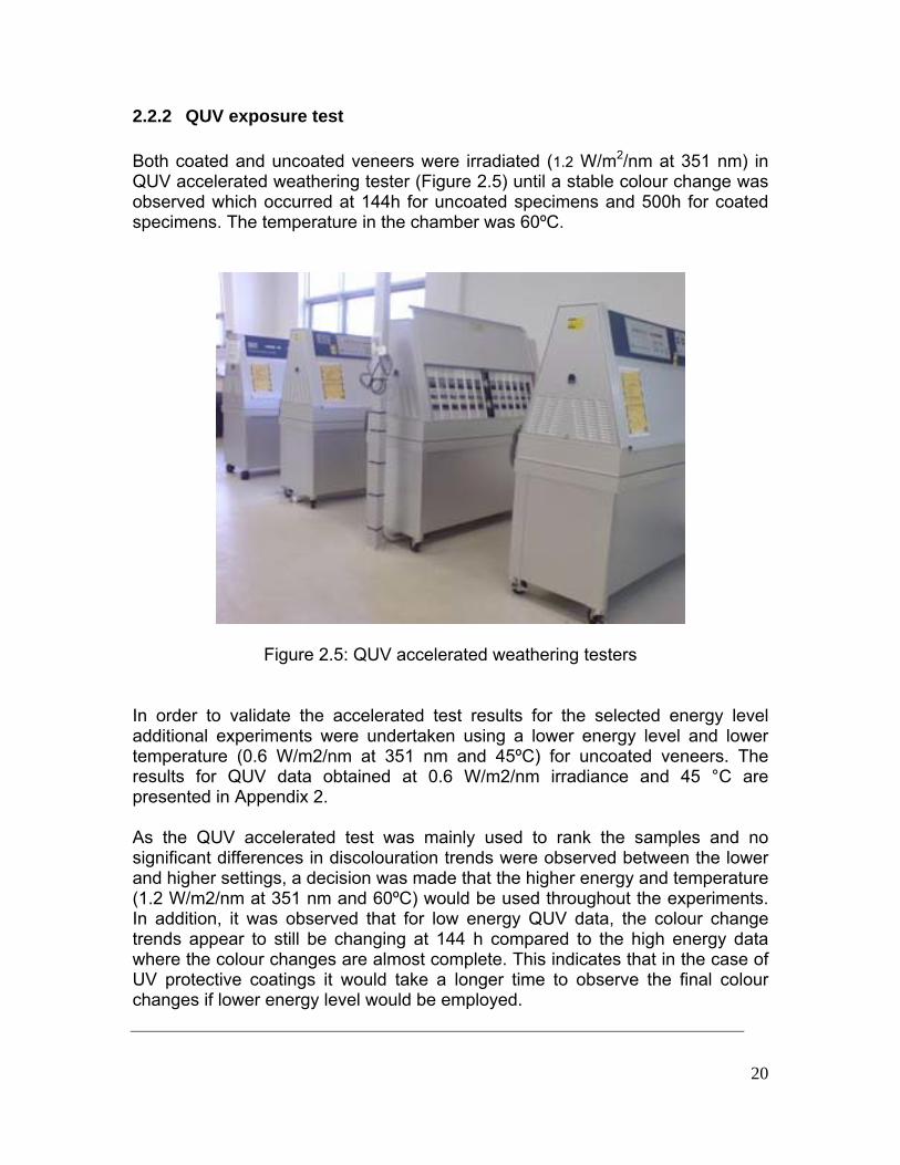
2.2.2 QUV exposure test ........................................................................20
2.3 Colour measurement ............................................................................21
3 Assessment of Unprotected Veneers ..........................................................22
4 Assessment of UV Protected Veneers.........................................................33
5 Assessment of the UV Protected vs. Unprotected Veneers.........................45
6 Summary and Recommendations................................................................47 Appendix 1: Correlation of QUV results to an in-house light box test used by
industry ...............................................................................................................50
Appendix 2: Comparison of QUV results at lower irradiance and temperature ...54
Appendix 3: Pictures of unprotected veneers before and after QUV exposure...58
Appendix 4: Pictures of unprotected veneers before and after QUV exposure...67 References .......................................................................................................103

6
List of Tables
Table 2.1: Description of the coatings systems nominated for QUV accelerated
test ......................................................................................................................17
Table 2.2: Coatings application specifications ....................................................18
Table 3.1: Average colour change of unprotected veneers.................................23
Table 4.1: Colour change data for coated veneer samples.................................33
Table A1. 1: Comparison between Mirotone test data and QUV test data..........51
Table A1. 2: Results for unprotected veneers as supplied by Mirotone ..............53
Table A2. 1: Colour change for unprotected veneers using lower irradiance level
(0.6 W/m2/nm and 45 °C)....................................................................................54
Table A3. 1: Images of unprotected veneer samples at initial time (control
sample) and after 144 hours of QUV exposure...................................................58
Table A4. 1: Pictures of protected veneer samples at initial time and after 500
hours of QUV exposure ......................................................................................67

7
List of Figures
Figure 2.1: Spectral power distribution of UV A 351 lamp and sunlight through
window glass. .....................................................................................................14
Figure 2.2: Example of the use of higher irradiance in QUV accelerated UV
exposure testing..................................................................................................15
Figure 2.3: Veneer adhesion to MDF..................................................................16
Figure 2.4: Spraying set-up.................................................................................19
Figure 2.5: QUV accelerated weathering testers ................................................20
Figure 2.6: Colour measurement set-up .............................................................21
Figure 3.1: Colour change of unprotected reconstituted veneers as a function of
UV exposure time ...............................................................................................24
Figure 3.2: Colour change of unprotected dyed veneers as a function of UV
exposure time .....................................................................................................24
Figure 3.3: Colour change of unprotected natural veneers as a function of UV
exposure time .....................................................................................................25
Figure 3.4: Colour change of selected unprotected veneers as a function of UV
exposure time .....................................................................................................26
Figure 3.5: ∆L colour component of unprotected reconstituted veneers as a
function of UV exposure time..............................................................................27
Figure 3.6: ∆L colour component of unprotected dyed veneers as a function of
UV exposure time ...............................................................................................27
Figure 3.7: ∆L colour component of unprotected natural veneers as a function of
UV exposure time ...............................................................................................28
Figure 3.8: ∆a colour component of unprotected reconstituted veneers as a
function of UV exposure time..............................................................................29
Figure 3.9: ∆a colour component of unprotected dyed veneers as a function of
UV exposure time ...............................................................................................29
Figure 3.10: ∆a colour component of unprotected natural veneers as a function of
UV exposure time ...............................................................................................30

8
Figure 3.11: ∆b colour component of unprotected reconstituted veneers as a
function of UV exposure time..............................................................................31
Figure 3.12: ∆b colour component of unprotected dyed veneers as a function of
UV exposure time ...............................................................................................31
Figure 3.13: ∆b colour component of unprotected natural veneers as a function of
UV exposure time ...............................................................................................32
Figure 4.1: Colour change as a function of UV exposure time for veneers coated
with 1A ................................................................................................................35
Figure 4.2: Colour change as a function of UV exposure time for veneers coated
with 1B ................................................................................................................35
Figure 4.3: Colour change as a function of UV exposure time for veneers coated
with 1C................................................................................................................36
Figure 4.4: Colour change as a function of UV exposure time for veneers coated
with 2 ..................................................................................................................36
Figure 4.5: Colour change as a function of UV exposure time for veneers coated
with 3A ................................................................................................................37
Figure 4.6: Colour change as a function of UV exposure time for veneers coated
with 3B ................................................................................................................37
Figure 4.7: Colour change as a function of UV exposure time for veneers coated
with 4A ................................................................................................................38
Figure 4.8: Colour change as a function of UV exposure time for veneers coated
with 4B ................................................................................................................38
Figure 4.9: Colour change as a function of UV exposure time for Reconstituted
R5 veneer coated with different coatings ............................................................39
Figure 4.10: Colour change as a function of UV exposure time for Reconstituted
R14 veneer coated with different coatings ..........................................................39
Figure 4.11: Colour change as a function of UV exposure time for Reconstituted
R8 veneer coated with different coatings ............................................................40
Figure 4.12: Colour change as a function of UV exposure time for Dyed D1
veneer coated with different coatings..................................................................40

9
Figure 4.13: Colour change as a function of UV exposure time for Dyed D7
veneer coated with different coatings..................................................................41
Figure 4.14: Colour change as a function of UV exposure time for Natural N3
veneer coated with different coatings..................................................................41
Figure 4.15: Colour change as a function of UV exposure time for Natural N4
veneer coated with different coatings..................................................................42
Figure 4.16: Colour change as a function of UV exposure time for Dyed D6
veneer coated with different coatings..................................................................42
Figure 4.17: Colour change as a function of UV exposure time for Reconstituted
R1 veneer coated with different coatings ............................................................43
Figure 4.18: Performance comparison of all 8 coatings examined .....................44
Figure 5.1: Comparison of coated (coating 2) and uncoated veneers after 144h
QUV....................................................................................................................46
Figure 5.2: Comparison of coated (coating 3B) and uncoated veneers after 144h
QUV....................................................................................................................47
Figure A1. 1: UV exposure cabinet used by Mirotone.........................................50
Figure A1. 2: Visual ranking of veneers from different light exposure apparatus.
............................................................................................................................52
Figure A2. 1: Colour changes for Reconstituted veneers at low irradiance.........55
Figure A2. 2: Comparison of colour changes for selected unprotected veneers at
low and high irradiance levels after 144 h in QUV ..............................................57

10
1 Background
There is an increasing use in Australia of reconstituted and dyed veneers imported from Europe. These veneers are used particularly in joinery, furniture and interior architectural applications. It is generally thought by the architects and interior designers that reconstituted and dyed veneers offer uniformity and evenness of colour and texture, which are well retained throughout service life. Recently it has been reported that there are a number of problems with reconstituted and dyed veneers due to discolouration upon exposure to UV light. Most susceptible to the discolouration are grey colour veneers which turn green when exposed to the UV light. However, veneer producers and customers have also reported problems with other colours of veneers. Colour change of the dyed wood veneer upon UV exposure is a complex process, which involves photo-initiated reaction, subsequent chemical oxidation, decomposition of lignin and extractives from the wood and the dye and other chemicals introduced during the dyeing process. Furthermore the discolouration caused by sunlight depends on the UV intensity and specific wavelength, photochemical reaction rate of lignin, and the chemical nature of the extractive and dyes. Protective coatings containing UV absorbers and UV stabilisers have been developed and are used to seal the wood veneer and reduce UV oxidation and discolouration. However, the existing commercially available products provide only a limited protection time. The above problems may have adverse effects on the use of natural (uncoloured) sliced veneers as the specifiers and users of veneers may believe that all veneers behave similarly. In view of the importance of these issues, the Australian veneer industry has recognised that a research project needs to be undertaken to develop an understanding of the UV discolouration of uncoloured veneers as well as reconstituted and dyed veneers, and to make recommendations on how this problem can be alleviated. A collaborative research study was undertaken by the Decorative Wood Veneer Association, CSIRO Manufacturing and Materials Technology and the University of Melbourne with the aim to investigate discolouration of selected veneers exposed to UV light and effectiveness of various coatings currently used by the industry in maintaining colour stability. The project was successful in receiving a financial support from the Forest and Wood Products R&D Corporation

11
This report presents the technical findings from:
iii) the discolouration of unprotected natural, reconstituted and dyed veneers when exposed to UV light
iv) the effectiveness of a range of commercial UV protective coatings and a CSIRO developed UV protective coating when used on selected natural, reconstituted and dyed veneers.
Finally, recommendations for the Australian veneer industry are presented in the report for the enhanced durability and colour retention of natural, reconstituted and dyed veneers when exposed to UV light.
2 Experimental
2.1 QUV accelerated weathering exposure
2.1.1 Selection of representative samples of veneers and coating systems for the UV exposure testing
Various types of veneers and a range of coating systems currently used on reconstituted and dyed wood veneers have been selected for the QUV accelerated weathering test to investigate the discolouration kinetics. Twenty seven veneers susceptible to UV discolouration were nominated by DWVA members for testing:
• Reconstituted veneers (15 types) • Dyed veneers (8 types) • Natural veneers (4 types)
Reconstituted veneers nominated for this project represent various colours which have shown the UV-light discolouration in service. Dyed veneers nominated for testing are dyed in Italy and then sold in Australia for the production of architectural and furniture products. Seven colours of Tasmanian Oak veneers and one colour of Myrtle have been nominated for the study. The natural veneers selected for testing are known as being susceptible to the UV-light discolouration.

12
Nine coating systems have been nominated for the study (Table 2.1):
• Coatings with and without UV-absorbers, currently used in furniture and interior finishing on reconstituted and dyed veneers (Akzolux, Mirotone and GVA).
• Coatings with UV-absorbers developed by Orica and CSIRO MMT. The involvement of these coatings in the study has been recommended by DWVA in order to evaluate “independent” systems which could be used by the veneer industry in the future if they prove to be effective protectors of the UV-light discolouration of veneers.
2.1.2 Test methodology Detailed methodology has been developed for the accelerated UV-light exposure testing. As there was a significant number of veneers and coatings nominated for the study the matrix of experiments have been carefully studied and optimised in order to meet the project time and budget restrictions. The first stage of the study involved UV-light exposure and assessment of uncoated/unprotective veneers. Two sets of uncoated veneer samples were tested. One set was tested at CSIRO Highett using QUV chamber with 351nm UV lamp. The second set of samples was sent to Mirotone’s R&D Laboratory in Sydney for in-house exposure to a metal halide lamp for benchmarking of veneer discolouration level. All samples were returned to CSIRO after exposure for colour change assessment. The aim of this additional experiment was to compare the results of CSIRO accelerated QUV test with the test currently used by the industry.
Samples assessment have been conducted in respect to colour difference (ΔEL*a*b*) and the changes in proportion between colour components L*, a* and b*. Visual assessment has been also used as ranking criteria. The visual ranking was undertaken by Mirotone Pty Ltd (coatings producer and supplier) and Elton Group (veneer importers) specialists.
The analysis of testing results from the 1st stage of the study enabled the project team to select veneers for the 2nd stage of the testing program which involves the testing of coated veneers. The 2nd stage of the study consisted in the selection of nine worst discoloured veneer types which subsequently have been coated with the nominated coating systems and investigated upon the UV exposure. The sample selection has been

13
performed based on UV discolouration rating and established ranking criteria, as follows:
• Two the worst UV-performing samples (based on colour measurements) from each veneer category (i.e. reconstituted1, dyed and natural veneer)
• In addition two veneers severely discoloured were selected based on a visual assessment although the results of their colourimetric evaluation were not showing very poor performance.
The QUV tests were carried out according to ASTM Standard Practices: ASTM G154 and G151.
2.1.3 QUV test considerations The standard ASTM G154 refers to operating procedures for using fluorescent UV light to reproduce the weathering effects that occur when materials are exposed to sunlight (either direct or through glass) [1]. ASTM G151 standard provides general procedures to be used when exposing non-metallic materials in accelerated fluorescent light test devices [2]. The ASTM G154 standard states that:
“the main application for UV-A 351 nm lamps is for simulation of the short and middle UV wavelength region of daylight which has been filtered through glass”.
Figure 2.1 compares the spectral power distribution obtained from these lamps and natural sunlight through glass. The analysis of the graph reveals that low wavelength end cut off for these lamps is similar to that of direct sunlight filtered through glass. It is also important to note that this wavelength also gives less severe results than using the shorter wavelength QUV lamps (e.g. 313 or 340 nm) which can lead to uncharacteristic results. Therefore, the selection of 351 nm wavelength for this study appeared to be easily justified.
1 The top two worst reconstituted veneers looked very similar in appearance. Therefore, the third worst discoloured veneer sample was additionally selected to be coated with protective formulations.

14
Figure 2.1: Spectral power distribution of UV A 351 lamp and sunlight through window glass.
In this study, the solar irradiance level of 1.2 W/m2/nm and the temperature of 60o C have been selected. It is not uncommon to increase the level of irradiance and still maintain realistic test conditions. This simply allows for faster results to be obtained. For example, the use of higher irradiance levels applying the solar eye irradiance control has been reported by a company manufacturing the QUV, Q-panel on its website (Figure 2.2) [3].

15
Figure 2.2: Example of the use of higher irradiance in QUV accelerated UV exposure testing
2.2 Description of experiments
2.2.1 Veneer samples preparation
2.2.1.1 Uncoated veneer samples All veneers selected for the test (Chapter 2.1.1) were 0.6 mm thick which is a typical thickness for currently produced decorative veneers both in Australia and overseas. The veneers were mounted or laminated onto a 7 mm section of MDF board (not clear). Veneers were glued onto large pieces of MDF board (1200 mm long x 1200 mm wide x 12 mm thick) using a sprayable contact adhesive (Laminex). Both the MDF board and loose side of the veneer were sprayed and allowed to become touch dry for approx. 10 min before adhering both surfaces together (Figure 2.4). Veneer samples were then pressed onto the board using a rolling pin.

16
Figure 2.3: Veneer adhesion to MDF Once the laminated veneers were dry, they were cut into smaller sections (75 x 155 mm) suitable for placement in the sample holders used for accelerated UV exposure. As a final step, the veneers were machine-sanded using 240 grit paper just prior to UV exposure and labelled. Capitals letters and numbers were assigned to each veneer samples referred to throughout this report. The coding system used for the veneer sample identification is as follows:
• R1 to R15 – reconstituted veneer • D1 to D8 – dyed veneer • N1 to N4 – natural veneer
Two replicates were tested for each veneer type considering the variability of wood products properties (i.e. density, grain orientation, etc.). The number of sample replicates was restricted to two by the limited QUV exposure room.
2.2.1.2 Coated veneer samples Eight coating formulations designed for interior furniture finishing have been nominated to be used on nine worst QUV discoloured veneers and tested to QUV exposure.

17
Capitals letters and numbers were assigned to each coating referred to throughout this report. The coding system used for the coatings identification is as follows:
• 1 to 4 – index assigned for suppliers • A to C – index assigned for supplied coating
The description of the coating systems used in this project is presented in Table 2.1. In addition, a CSIRO coating was also prepared for use in this study as an independent coating system, however some formulation issues arose and the coating could not be optimised in the time constraints of the project. It was therefore decided not to include the CSIRO coating. Two samples of each veneer specimen were prepared prior to coating as per description from previous section (Chapter 2.2.1.1). The effective coating process for various coating systems directly followed the application methods specified by suppliers. The number of coats applied, wet film weight per coat, recoating time, sending sequence and application procedure which were used for each type of coating are listed in Table 2.2.
Table 2.1: Description of the coatings systems nominated for QUV accelerated test
No Coating code Description
1
1A
Two pack polyurethane
Two pack polyurethane
2 1B Two pack acrylic modified polyurethane with UV additives
3 1C Two pack acrylic modified polyurethane
4
2
Two pack isolator
Two pack acrylic sealer with UV additives
Two pack acrylic matt topcoat with UV additives
5
3A
Two pack acrylic modified sealer coat with UV additives
Two pack acrylic modified top coat with UV additives
6
3B
Two pack polyurethane isolator
Two pack polyurethane sealer
Two pack polyurethane topcoat
7 4A Ready mixed (aliphatic moisture-cured polyurethane with UV additives)
8 4B Ready mixed (synthetic polymer, mineral turpentine, stoddard solvent)

18
Table 2.2: Coatings application specifications
Coating code No of coats Wet film weight/coat Recoating time Sending Application (g/m2) hours (h) (320 grit paper)
1A Sealer x1 150 approx. 16 h yes Spray
Topcoat x2 130 approx. 16 h 1st after 1st topcoat
1B Topcoat x3 150 approx. 16 h 1st and 2nd coat after 1st and 2nd coat Spray
1C Topcoat x3 150 approx. 16 h 1st and 2nd coat after 1st and 2nd coat Spray
2 Isolator x1 100 1 h - Spray
Sealer x2 180 1 h 1st coat, approx 16 h 2nd coat after 2nd sealer coat
Topcoat x1 180 -
3A Sealer x1 150 2 h yes Spray
Sealer x2 150 10 min 1st coat, approx. 18 h 2nd coat after 2nd sealer coat
Topcoat x2 130 -
3B Isolator x1 100 2 h yes Spray
Sealer x3 150 10 min 1st and 2nd coat, approx. 18 h 3rd coat after 3rd coat
Topcoat x1 140 -
4A Topcoat x4 130 approx 24 h 1st, 2nd and 3rd coat after 1st, 2nd and 3rd coat Brush
4B Topcoat x3 100 approx 24 h 1st and 2nd coat after 1st, 2nd coat Brush

19
A Yamaha programmable spraying robot with pressure pot (1.5 to 2mm orifice with pressure pot air-cap) was employed for spraying (Figure 2.4). Two samples were sprayed at a time.
Figure 2.4: Spraying set-up As a general rule, the following spraying procedure was used for all coating formulations, assuring the application consistency: The veneer samples were machine-sanded just before coating by using 240
grit paper. All sanding dust was removed using air gun. Two spraying applications (runs) were carried out for each coat. The time
interval between the two consecutive runs was 30 sec. The weight wet film was measured before each coating application and
adjusted accordingly by using dummy sample (paper covered sample). A light sanding between intermediate coats was carried out manually for all
samples by using 320 grit paper. The amount sanded away was about 0.05g per sample. All sanding dust was removed using air gun.
Brushing was also employed in the cases where the coating supplier considered it among the preferable application methods. The samples were brushed along the full length of the surface in the grain direction by using a foam brush. Each sample was weighted and brushed until the recommended wet film weight was achieved.
20
2.2.2 QUV exposure test Both coated and uncoated veneers were irradiated (1.2 W/m2/nm at 351 nm) in QUV accelerated weathering tester (Figure 2.5) until a stable colour change was observed which occurred at 144h for uncoated specimens and 500h for coated specimens. The temperature in the chamber was 60ºC.
Figure 2.5: QUV accelerated weathering testers In order to validate the accelerated test results for the selected energy level additional experiments were undertaken using a lower energy level and lower temperature (0.6 W/m2/nm at 351 nm and 45ºC) for uncoated veneers. The results for QUV data obtained at 0.6 W/m2/nm irradiance and 45 °C are presented in Appendix 2. As the QUV accelerated test was mainly used to rank the samples and no significant differences in discolouration trends were observed between the lower and higher settings, a decision was made that the higher energy and temperature (1.2 W/m2/nm at 351 nm and 60ºC) would be used throughout the experiments. In addition, it was observed that for low energy QUV data, the colour change trends appear to still be changing at 144 h compared to the high energy data where the colour changes are almost complete. This indicates that in the case of UV protective coatings it would take a longer time to observe the final colour changes if lower energy level would be employed.

21
As described in Chapter 2.1.2, in addition to QUV testing, a separate set of unprotected veneers was prepared and tested at Mirotone’s laboratory, using an in-house light box. The results are presented in Appendix 1. 2.3 Colour measurement
The colour measurement was undertaken using a BYK-Gardner digital colour apparatus. The CIELab colour system (ΔEL*a*b*, ΔL*, Δa* and Δb*) and the following specifications were used:
• Light source type D65; • Observation angle of 10º; • Calibration with ceramic standard; • Sample averaging n=8
The colour measurements were taken in eight different points on the UV exposed surface of each sample due to the very high variability within the same range colour displayed by the wood grain and the very narrow area the colour meter can read (about 4 mm2). To ensure that all the colour readings will be taken in exactly the same spots at different stages during the QUV accelerated exposure test, a colour measurement template was built (Figure 2.6).
Figure 2.6: Colour measurement set-up L*, a* and b* colour coordinates for each sample were determined before and after exposure to accelerated weathering. These values were used to calculate the colour change ΔEL*a*b* as a function of the UV irradiation period according to the following equations:

22
∗∗∗ −=Δ if LLL ∗∗∗ −=Δ if aaa ∗∗∗ −=Δ if bbb
222**,*,
∗∗∗ Δ+Δ+Δ=Δ baLE baL where ΔL*, Δa*, and Δb* are the changes between the initial and several interval values.
+ ΔL* means that the sample is lighter than the standard - ΔL* means that the sample is darker than the standard + Δa* means that the sample is redder than the standard - Δa* means that the sample is greener than the standard + Δb* means that the sample is yellower than the standard - Δb* means that the sample is bluer than the standard
A low ΔEL*a*b* corresponds to a low colour change or a stable colour. It is generally considered that a colour change above five is perceived by the naked eye and depending on the application the change could be more or less significant.
3 Assessment of Unprotected Veneers
A summary of the colour change for unprotected veneer samples is presented in Table 3.1 and also graphically in Figures 3.1 – 3.3.

23
Table 3.1: Average colour change of unprotected veneers
Veneer code ΔE24 mean ΔE48 mean ΔE72 mean ΔE96 mean ΔE120 mean ΔE144 mean
R1 6.75 8.80 10.09 11.37 11.89 12.10
R2 2.81 5.01 6.11 7.30 7.97 8.44
R3 11.64 13.43 13.94 14.20 15.35 15.23
R4 2.10 3.34 3.87 4.75 5.24 5.32
R5 13.23 14.86 15.60 16.16 17.06 17.18
R6 7.79 10.15 11.13 12.54 13.53 13.72
R7 1.81 3.74 4.53 5.76 6.48 6.62
R8 12.77 13.54 13.79 13.72 14.28 14.16
R9 3.11 5.55 6.88 8.26 9.13 9.50
R10 9.69 11.37 12.23 12.24 13.27 13.79
R11 1.73 1.33 1.85 1.13 1.10 1.25
R12 8.77 11.64 13.11 14.54 15.72 16.00
R13 3.43 3.53 3.87 3.84 4.10 4.35
R14 14.17 16.38 17.73 17.98 18.67 19.08
R15 5.19 7.14 8.64 9.29 10.32 11.32
D1 20.16 23.28 25.11 25.89 27.15 27.23
D2 2.48 4.24 4.96 6.32 7.93 7.54
D3 5.28 6.82 7.59 8.47 9.15 9.32
D4 11.72 13.39 14.59 14.71 15.57 15.89
D5 3.12 3.92 3.91 5.01 5.88 5.56
D6 7.46 8.75 8.90 9.41 10.03 9.87
D7 12.22 14.05 14.82 15.92 16.96 17.11
D8 1.04 1.98 2.58 3.84 4.68 4.94
N1 12.14 12.09 11.72 11.49 12.03 11.64
N2 9.65 9.80 9.29 8.98 9.07 8.76
N3 17.15 19.02 19.57 19.60 20.19 20.23
N4 17.95 18.98 19.46 19.62 20.23 20.67

24
Colour change (ΔElab) for Reconstituted Veneers
0.002.004.006.008.00
10.0012.0014.0016.0018.0020.00
24 h 48 h 72 h 96 h 120 h 144 h
UV exposure time (h)
ΔE
(lab)
R1R2R3R4R5R6R7R8R9R10R11R12R13 R14 R15
Figure 3.1: Colour change of unprotected reconstituted veneers as a function of UV exposure time
Colour change (ΔElab) for Dyed Veneers
0.00
5.00
10.00
15.00
20.00
25.00
30.00
24 h 48 h 72 h 96 h 120 h 144 h
UV exposure time (h)
ΔE(
lab)
D1D2D3D4D5D6D7D8
Figure 3.2: Colour change of unprotected dyed veneers as a function of UV exposure time

25
Colour change (ΔElab) for Natural Veneers
0.00
5.00
10.00
15.00
20.00
25.00
30.00
24 h 48 h 72 h 96 h 120 h 144 h
UV exposure time (h)
ΔE(
lab)
N1N2N3N4
Figure 3.3: Colour change of unprotected natural veneers as a function of UV exposure time
The best performing veneer was the reconstituted veneer, R11. After 144 h of accelerated UV exposure this unprotected veneer only resulted in a very negligible change in ∆E of 1.25. This was followed closely by the dyed veneer, D8 which gave a ∆E change of 4.94 after 144 h exposure. In the case of natural veneers that were examined in this study, the best performance was observed with N2. This veneer gave a ∆E of 8.76 after the 144 h of UV exposure. Figure 3.4 shows the colour changes of the selected worst performing veneers from each of the reconstituted, dyed and natural types. Selection was based largely on those that gave the greatest change in ∆E. In the case of the reconstituted veneers, R8 was selected together with R5 and R14 since it gave a higher change in ∆E at an early stage in the UV exposure. For the dyed veneers the worst performing samples were D1 and D7. In the case of natural veneers, the worst samples were N3 and N4.

26
Colour change (ΔElab) for Selected Veneers
10.00
15.00
20.00
25.00
30.00
24 h 48 h 72 h 96 h 120 h 144 h
UV exposure time (h)
ΔE(
lab)
R5R8R14 D1D7N3N4
Figure 3.4: Colour change of selected unprotected veneers as a function of UV exposure time
The overall contribution to ∆E is made up from ∆L, ∆a and ∆b as described in Chapter 2.3 of this report. The overall trend observed with the worst performing veneers from each category was a shift in ∆L in the negative direction. This means that that sample has become darker compared to the standard with no UV exposure. This was not the case for all veneers, and in some cases the shift was towards a positive ∆L, which meant that the samples had become lighter. An example of this is seen with the reconstituted veneer, R1. The changes in ∆L are represented graphically in Figures 3.5 - 3.7 for each veneer category.

27
ΔL for Reconstituted Veneers
-10.00
-5.00
0.00
5.00
10.00
15.00
24 h 48 h 72 h 96 h 120 h 144 h
UV exposure time (h)
ΔL
R1R2R3R4R5R6R7R8R9R10R11R12R13 R14 R15
Figure 3.5: ∆L colour component of unprotected reconstituted veneers as a function of UV exposure time
ΔL for Dyed Veneers
-15.00
-10.00
-5.00
0.00
5.00
24 h 48 h 72 h 96 h 120 h 144 h
UV exposure time (h)
ΔL
D1D2D3D4D5D6D7D8
Figure 3.6: ∆L colour component of unprotected dyed veneers as a function of UV exposure time

28
ΔL for Natural Veneers
-18.00
-16.00
-14.00
-12.00
-10.00
-8.00
-6.00
-4.00
-2.00
0.0024 h 48 h 72 h 96 h 120 h 144 h
UV exposure time (h)
ΔL
N1N2N3N4
Figure 3.7: ∆L colour component of unprotected natural veneers as a function of UV exposure time
Another component of the overall colour change is ∆a. A positive shift in ∆a indicates that the sample has become redder compared to the unexposed standard while a negative ∆a shift indicates that the sample is greener. In the case of the veneers that show the worst performance the trend is a shift towards a positive ∆a, or a redder colour. Figures 3.8 - 3.10 represent the changes in ∆a graphically as a function of UV exposure time for each veneer category.

29
Δa for Reconstituted Veneers
-6.00
-4.00
-2.00
0.00
2.00
4.00
24 h 48 h 72 h 96 h 120 h 144 h
UV exposure time (h)
Δa
R1R2R3R4R5R6R7R8R9R10R11R12R13 R14 R15
Figure 3.8: ∆a colour component of unprotected reconstituted veneers as a function of UV exposure time
Δa for Dyed Veneers
-8.00
-6.00
-4.00
-2.00
0.00
2.00
4.00
6.00
8.00
24 h 48 h 72 h 96 h 120 h 144 h
UV exposure time (h)
Δa
D1D2D3D4D5D6D7D8
Figure 3.9: ∆a colour component of unprotected dyed veneers as a function of UV exposure time

30
Δa for Natural Veneers
0.00
2.00
4.00
6.00
8.00
24 h 48 h 72 h 96 h 120 h 144 h
UV exposure time (h)
Δa
N1N2N3N4
Figure 3.10: ∆a colour component of unprotected natural veneers as a function of UV exposure time
The final component contributing to the overall ∆E colour change is the yellow-blue colour scale, or ∆b. A positive shift in ∆b values indicates that the sample is yellower compared to the unexposed standard while a negative shift in ∆b represents a bluer sample relative to the standard. The overall trend for the veneers examined here is a shift towards a more yellow colour. The natural veneers show the least amount of change with respect to this component of colour change. Data for each veneer category is represented in Figures 3.11 – 3.13.

31
Δb for Reconstituted Veneers
-5.00
0.00
5.00
10.00
15.00
20.00
24 h 48 h 72 h 96 h 120 h 144 h
UV exposure time (h)
Δb
R1R2R3R4R5R6R7R8R9R10R11R12R13 R14 R15
Figure 3.11: ∆b colour component of unprotected reconstituted veneers as a function of UV exposure time
Δb for Dyed Veneers
0.00
5.00
10.00
15.00
20.00
25.00
24 h 48 h 72 h 96 h 120 h 144 h
UV exposure time (h)
Δb
D1D2D3D4D5D6D7D8
Figure 3.12: ∆b colour component of unprotected dyed veneers as a function of UV exposure time

32
Δb for Natural Veneers
0.00
5.00
10.00
15.00
20.00
24 h 48 h 72 h 96 h 120 h 144 h
UV exposure time (h)
Db
N1N2N3N4
Figure 3.13: ∆b colour component of unprotected natural veneers as a function of UV exposure time
As mentioned previously, on the basis of the magnitude of ∆E colour change values alone for the unprotected veneers it was possible to select the worst veneers from each category for the next stage of the study, i.e. the examination of UV protective coatings on veneers. In summary, the selected samples based on this criteria were: Reconstituted R14, R5 and R8 Dyed D1 and D7 Natural N3 and N4 In addition to ∆E as selection criteria, it was decided to include a further two samples that would be of interest based on their visual appearance alone. The samples of reconstituted veneer R1 and dyed veneer D6 were also included in the next stage of the study. These samples differ from those mentioned above since they gave a shift towards a lighter ∆L and while the overall measured colour change was not as high as some of the others, it is likely that this visual degree of colour “fading” would not be considered acceptable in the veneer industry. The values for ∆a were also different to the other selected samples, shifting towards green. ∆b values for these and selected samples followed the same trend, i.e. a shift towards yellow. The images of the veneers are presented in Table A3. 1, Appendix 3.

33
4 Assessment of UV Protected Veneers
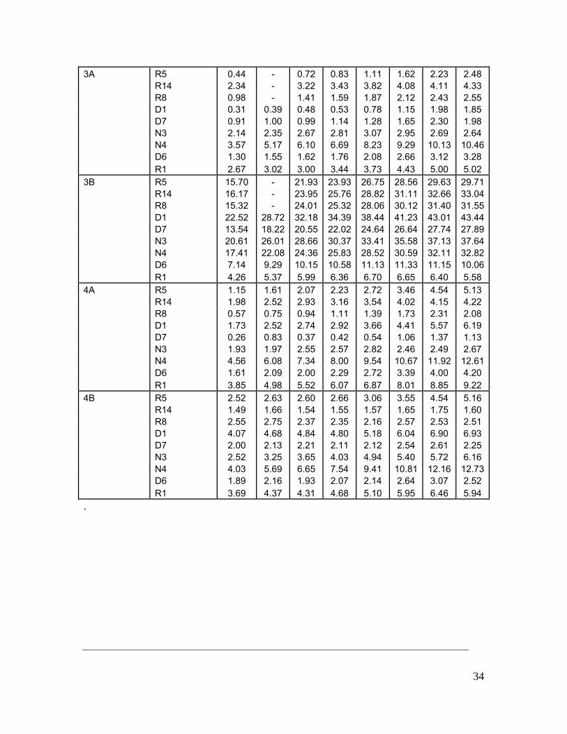
Table 4.1 summarizes the measured colour changes for the coated veneer samples. Data is also graphically represented in Figures 4.1 – 4.16, showing both the trends across different veneers for a particular coating type as well as the trends for a particular veneer type with different coatings.
Table 4.1: Colour change data for coated veneer samples Coating code Sample code ΔE20 ΔE40 ΔE60 ΔE80 ΔE144 ΔE240 ΔE336 ΔE500 1A R5 9.51 12.46 14.34 15.76 18.57 21.21 23.33 24.11 R14 10.40 13.76 15.86 17.50 20.86 23.96 26.63 27.67 R8 12.68 15.77 17.53 18.82 21.12 23.11 24.81 25.12 D1 21.90 26.14 28.60 30.30 33.60 36.57 38.88 39.81 D7 9.27 12.14 13.96 15.31 18.17 20.88 23.18 23.80 N3 16.61 20.10 22.09 23.51 26.21 28.65 30.68 31.43 N4 10.39 13.20 14.78 15.91 18.27 20.24 21.94 22.81 D6 6.08 7.07 7.61 7.93 8.63 9.43 10.44 10.11 R1 3.23 4.56 5.44 6.33 8.29 10.35 11.97 12.351B R5 0.64 0.89 1.03 1.25 1.58 2.24 3.25 3.65 R14 2.64 3.26 3.47 3.70 3.91 4.19 4.13 4.07 R8 1.03 1.34 1.38 1.50 1.61 1.88 1.91 1.84 D1 0.41 0.49 0.59 0.62 0.96 1.35 2.14 2.34 D7 0.51 0.64 0.51 0.63 0.50 0.79 0.93 0.85 N3 2.91 3.35 3.55 3.62 3.82 3.69 3.43 3.30 N4 4.04 5.91 7.07 7.89 9.85 11.29 12.29 13.16 D6 1.56 1.87 2.06 2.27 2.58 3.26 3.66 3.78 R1 2.30 3.00 3.16 3.47 3.99 4.86 5.41 5.59 1C R5 8.82 11.87 13.95 15.46 18.68 21.24 23.01 23.48 R14 10.03 12.80 14.59 15.89 18.87 21.63 23.89 24.79 R8 10.99 14.32 16.56 18.08 20.94 22.80 23.92 24.13 D1 20.40 25.01 27.60 29.87 33.81 36.95 38.64 39.48 D7 7.42 10.55 12.68 14.33 17.76 20.52 22.28 23.08 N3 13.42 16.82 18.80 20.47 23.65 26.17 27.78 28.59 N4 8.76 11.61 13.54 14.98 18.22 20.91 22.96 23.93 D6 6.34 7.18 7.61 7.89 8.46 8.96 9.35 9.07 R1 3.12 4.53 5.57 6.51 8.61 10.82 12.35 12.782 R5 0.39 0.40 0.79 0.99 1.51 2.25 3.13 3.65 R14 1.89 2.25 2.43 2.58 2.68 2.59 2.32 2.43 R8 0.54 0.67 0.80 0.90 1.17 1.38 1.55 1.39 D1 0.99 1.27 1.57 1.67 2.13 2.80 3.66 3.95 D7 0.63 0.85 0.96 1.01 1.30 1.57 2.15 1.84 N3 2.10 2.19 2.39 2.40 2.48 2.31 2.35 2.56 N4 3.63 5.21 6.22 6.96 8.67 9.90 10.90 11.91 D6 1.28 1.45 1.64 1.74 2.01 2.57 3.10 2.93 R1 2.29 2.63 2.84 3.07 3.56 4.20 4.68 4.71
34
3A R5 0.44 - 0.72 0.83 1.11 1.62 2.23 2.48 R14 2.34 - 3.22 3.43 3.82 4.08 4.11 4.33 R8 0.98 - 1.41 1.59 1.87 2.12 2.43 2.55 D1 0.31 0.39 0.48 0.53 0.78 1.15 1.98 1.85 D7 0.91 1.00 0.99 1.14 1.28 1.65 2.30 1.98 N3 2.14 2.35 2.67 2.81 3.07 2.95 2.69 2.64 N4 3.57 5.17 6.10 6.69 8.23 9.29 10.13 10.46 D6 1.30 1.55 1.62 1.76 2.08 2.66 3.12 3.28 R1 2.67 3.02 3.00 3.44 3.73 4.43 5.00 5.02 3B R5 15.70 - 21.93 23.93 26.75 28.56 29.63 29.71 R14 16.17 - 23.95 25.76 28.82 31.11 32.66 33.04 R8 15.32 - 24.01 25.32 28.06 30.12 31.40 31.55 D1 22.52 28.72 32.18 34.39 38.44 41.23 43.01 43.44 D7 13.54 18.22 20.55 22.02 24.64 26.64 27.74 27.89 N3 20.61 26.01 28.66 30.37 33.41 35.58 37.13 37.64 N4 17.41 22.08 24.36 25.83 28.52 30.59 32.11 32.82 D6 7.14 9.29 10.15 10.58 11.13 11.33 11.15 10.06 R1 4.26 5.37 5.99 6.36 6.70 6.65 6.40 5.58 4A R5 1.15 1.61 2.07 2.23 2.72 3.46 4.54 5.13 R14 1.98 2.52 2.93 3.16 3.54 4.02 4.15 4.22 R8 0.57 0.75 0.94 1.11 1.39 1.73 2.31 2.08 D1 1.73 2.52 2.74 2.92 3.66 4.41 5.57 6.19 D7 0.26 0.83 0.37 0.42 0.54 1.06 1.37 1.13 N3 1.93 1.97 2.55 2.57 2.82 2.46 2.49 2.67 N4 4.56 6.08 7.34 8.00 9.54 10.67 11.92 12.61 D6 1.61 2.09 2.00 2.29 2.72 3.39 4.00 4.20 R1 3.85 4.98 5.52 6.07 6.87 8.01 8.85 9.22 4B R5 2.52 2.63 2.60 2.66 3.06 3.55 4.54 5.16 R14 1.49 1.66 1.54 1.55 1.57 1.65 1.75 1.60 R8 2.55 2.75 2.37 2.35 2.16 2.57 2.53 2.51 D1 4.07 4.68 4.84 4.80 5.18 6.04 6.90 6.93 D7 2.00 2.13 2.21 2.11 2.12 2.54 2.61 2.25 N3 2.52 3.25 3.65 4.03 4.94 5.40 5.72 6.16 N4 4.03 5.69 6.65 7.54 9.41 10.81 12.16 12.73 D6 1.89 2.16 1.93 2.07 2.14 2.64 3.07 2.52 R1 3.69 4.37 4.31 4.68 5.10 5.95 6.46 5.94 .

35
Coating 1A
0.00
10.00
20.00
30.00
40.00
50.00
20 h 40 h 60 h 80 h 144 h 240 h 336 h 500 hUV Exposure time (h)
ΔE
R5 R14 R8D1 D7N3 N4D6 R1
Figure 4.1: Colour change as a function of UV exposure time for veneers coated
with 1A
Coating 1B
0.002.004.006.008.00
10.0012.0014.00
20 h 40 h 60 h 80 h 144 h 240 h 336 h 500 h
UV Exposure time (h)
ΔE
R5 R14 R8D1 D7N3 N4D6 R1
Figure 4.2: Colour change as a function of UV exposure time for veneers coated with 1B

36
Coating 1C
0.00
10.00
20.00
30.00
40.00
50.00
20 h 40 h 60 h 80 h 144 h 240 h 336 h 500 hUV Exposure time (h)
ΔE
R5 R14 R8D1 D7N3 N4D6 R1
Figure 4.3: Colour change as a function of UV exposure time for veneers coated with 1C
Coating 2
0.00
2.00
4.00
6.00
8.00
10.00
12.00
14.00
20 h 40 h 60 h 80 h 144 h 240 h 336 h 500 h
UV Exposure time (h)
ΔE
R5 R14 R8D1 D7N3 N4D6 R1
Figure 4.4: Colour change as a function of UV exposure time for veneers coated with 2

37
Coating 3A
0.00
2.00
4.00
6.00
8.00
10.00
12.00
20 h 40 h 60 h 80 h 144 h 240 h 336 h 500 h
UV Exposure time (h)
ΔE
R5 R14 R8D1 D7N3 N4D6 R1
Figure 4.5: Colour change as a function of UV exposure time for veneers coated with 3A
Coating 3B
0.005.00
10.0015.0020.0025.0030.0035.0040.0045.0050.00
20 h 40 h 60 h 80 h 144 h 240 h 336 h 500 h
UV Exposure time (h)
ΔE
R5 R14 R8D1 D7N3 N4D6 R1
Figure 4.6: Colour change as a function of UV exposure time for veneers coated with 3B

38
Coating 4A
0.002.004.006.008.00
10.0012.0014.00
20 h 40 h 60 h 80 h 144 h 240 h 336 h 500 hUV Exposure time (h)
ΔE
R5 R14 R8D1 D7N3 N4D6 R1
Figure 4.7: Colour change as a function of UV exposure time for veneers coated with 4A
Coating 4B
0.002.004.006.008.00
10.0012.0014.00
20 h 40 h 60 h 80 h 144 h 240 h 336 h 500 hUV Exposure time (h)
ΔE
R5 R14 R8D1 D7N3 N4D6 R1
Figure 4.8: Colour change as a function of UV exposure time for veneers coated with 4B

39
Reconstituted R5 veneer
05
101520253035
20 h 40 h 60 h 80 h 144 h 240 h 336 h 500 h
UV exposure time (h)
ΔE(
Lab)
1A
1B
1C
2
3A
3B
4A
4B
Figure 4.9: Colour change as a function of UV exposure time for Reconstituted R5 veneer coated with different coatings
Reconstituted R14 venner
05
101520253035
20 h 40 h 60 h 80 h 144 h 240 h 336 h 500 h
UV exposure time (h)
ΔE(
Lab)
1A1B1C23A3B4A4B
Figure 4.10: Colour change as a function of UV exposure time for Reconstituted R14 veneer coated with different coatings

40
Reconstituted R8 veneer
05
101520253035
20 h 40 h 60 h 80 h 144 h 240 h 336 h 500 h
UV exposure time (h)
ΔE(
Lab)
1A1B1C23A3B4A4B
Figure 4.11: Colour change as a function of UV exposure time for Reconstituted R8 veneer coated with different coatings
Dyed D1 veneer
0
10
20
30
40
50
20 h 40 h 60 h 80 h 144 h 240 h 336 h 500 h
UV exposure time (h)
ΔE(
Lab)
1A1B1C23A3B4A4B
Figure 4.12: Colour change as a function of UV exposure time for Dyed D1 veneer coated with different coatings

41
Dyed D7 veneer
05
1015202530
20 h 40 h 60 h 80 h 144 h 240 h 336 h 500 h
UV exposure time (h)
ΔE(
Lab)
1A1B1C23A3B4A4B
Figure 4.13: Colour change as a function of UV exposure time for Dyed D7 veneer coated with different coatings
Natural N3 veneer
0
10
20
30
40
20 h 40 h 60 h 80 h 144 h 240 h 336 h 500 h
UV exposure time (h)
ΔE(
Lab)
1A1B1C23A3B4A4B
Figure 4.14: Colour change as a function of UV exposure time for Natural N3 veneer coated with different coatings

42
Natural N4 veneer
05
1015202530
20 h 40 h 60 h 80 h 144 h 240 h 336 h 500 h
UV exposure time (h)
ΔE(
Lab)
1A1B1C23A4A4B
Figure 4.15: Colour change as a function of UV exposure time for Natural N4 veneer coated with different coatings
Dyed D6 veneer
02468
1012
20 h 40 h 60 h 80 h 144 h 240 h 336 h 500 h
UV exposure time (h)
ΔE(
Lab)
1A1B1C23A3B4A4B
Figure 4.16: Colour change as a function of UV exposure time for Dyed D6 veneer coated with different coatings

43
Reconstituted R1 veneer
02468
101214
20 h 40 h 60 h 80 h 144 h 240 h 336 h 500 h
UV exposure time (h)
ΔE(
Lab)
1A1B1C23A3B4A4B
Figure 4.17: Colour change as a function of UV exposure time for Reconstituted
R1 veneer coated with different coatings
Figure 4.18 compares the performance of all 8 coatings examined after 500 h of QUV exposure. It is clear that significant differences in performance exist within the coatings. The best overall performing coatings out of those in current commercial use for the veneer industry were the 1B (acrylic modified polyurethane with UV additives), 2 (acrylic/urethane with UV additives) and 3A (modified acrylic with UV additives) coatings. The 1A (polyurethane), 1C (acrylic modified polyurethane) and 3B (polyurethane) did not perform very well in comparison. The coatings 4 gave very good protection with values of colour change that were in a similar range to the better performing 1, 2 and 3 coatings.

44
R5
R14
R
8D
1 D
7N
3 N
4
D6
R1
23A
1B4B
4A1A
1C3B0
51015202530354045
ΔE
Comparison of different coatings colour change at 500h
23A1B4B4A1A1C3B
Figure 4.18: Performance comparison of all 8 coatings examined
From Figure 4.18 it is apparent that the natural veneer N4 is the veneer resulting in the largest colour changes across all the coatings examined. Both the dyed veneer D6 and reconstituted veneer R1 resulted in the lowest overall colour changes across all coatings. For example, the D6 and R1 veneers have performed very well with the coatings 3B, 1C and 1A, whilst all other veneers did not perform as well with these 3 coatings. The data represented in Figure 4.18 enables a fairly rapid assessment of a particular coating performance for a particular veneer to be made. This data provides an extremely valuable assessment tool to the veneer industry, enabling end users to choose a particular combination of veneer and coating designed for maximum durability and lowest UV discolouration. The images of all examined UV protected veneers before and after QUV exposure are presented in Table A4. 1, Appendix 4.

45
The use of acrylic and polyurethane clear coatings to protect wood from UV degradation have been previously reported in the literature [4, 5]. However, authors report that these coatings can still be susceptible to discolouration and yellowing induced by UV light. UV light absorbers to screen the UV light are critical in reducing the photodiscolouration. As well as UV absorbing additives, Hindered Amine Light Scavengers (HALS) also exhibit a synergistic effect and can elongate the service life of the light absorber and consequently, that of the coating and veneer itself. In this study the coatings without any UV additives did not perform very well compared to those containing UV absorbers. An example is the comparison of 3A coating (containing UV additives) which gave lower colour change compared to 3B (no UV additives). Similarly, 1B coating, containing UV additives also performed better than the same coating without UV additives (1C). What is not clear from the available manufacturer’s information is the actual chemical nature of the UV additives used. While this information is valuable in optimising the UV durability of the coatings, this investigation is beyond the scope of the current project. It also appears that acrylic modified polyurethanes give better performance compared to polyurethanes alone. The exact chemical nature of the polymer is important and without access to further proprietary information from the manufacturers, it is difficult to compare these coatings further. The need to develop a standardised method for monitoring and developing new wood finishes has previously been recognised by the European community [6]. This European study involved ten wood research institutes and four industrial partners who manufacture wood coatings. Although the study involved correlation to outdoor weathering, similar issues need to be addressed for the use of veneers in indoor applications. For instance, it was recognised that the test methods should be easily accessible to small and medium sized companies. These methods should also be reproducible and allow for rapid evaluation of coatings in a short period of time. The QUV method used in both this study and the European study appears to fit these criteria. Recommendations are discussed in the following section.
5 Assessment of the UV Protected vs. Unprotected Veneers
Figure 5.1 shows the comparison of colour change for veneers with and without the use of a good UV protective coating. The example shown here is with the coating 2. Clearly, the use of a good coating can significantly reduce discolouration caused by UV light exposure. However, if the correct coating is not used the results can be quite different.

46
R5
R14
R8
D1
D7
N3
N4
D6
R1
coated with coating 2uncoated
05
1015202530
ΔE
Coated (Coating 2) Vs Uncoated veneers
Figure 5.1: Comparison of coated (coating 2) and uncoated veneers after 144h QUV
Figure 5.2 shows the comparison of colour change for the same veneers using a poor performing coating, e.g. 3B. This particular example shows that the majority of observed colour changes can appear slightly worse than those for the veneers without any coating at all. A likely explanation for this is the UV degradation of the polymer coating itself. As mentioned previously, this coating does not contain any UV additives and unlike the 3A coating, which performed very well, the 3B coating gives higher values of discolouration. These examples illustrate how important it is to select the most appropriate coating to extend the durability of the veneer.

47
R5
R14
R8
D1
D7
N3
N4
D6
R1
coated with coating 3Buncoated
05
10152025303540
ΔE
Coated (coating 3B) Vs Uncoated veneers
Figure 5.2: Comparison of coated (coating 3B) and uncoated veneers after 144h QUV
6 Summary and Recommendations
A selection of 27 unprotected veneer samples have been assessed and colour difference measurements were collected for 15 reconstituted, 8 dyed and 4 natural veneers. The following observations were made after 144 h QUV A exposure:
• The veneers that performed best and showed the least amount of UV discolouration were identified as:
Reconstituted R11 (ΔE = 1.25) Dyed D8 (ΔE = 4.94) Natural N2 (ΔE = 8.76)
• The veneers that performed the worst and showed the greatest amount of
UV discolouration were identified as:
Reconstituted R14 (ΔE = 17.77), R5 (ΔE = 17.18) and R8 (ΔE = 14.16)

48
Dyed D1 (ΔE = 27.23) and
D7 (ΔE = 17.11)
Natural N3 (ΔE = 20.13) and N4 (ΔE = 20.67)
• The overall trends in colour change for the worst performing veneers based on greatest colour difference changes were:
o A shift towards negative ΔL (i.e. sample had become darker compared to unexposed reference sample)
o A shift towards positive Δa (i.e. sample had become redder), and o A shift towards positive Δb (i.e. sample had become yellower).
• Selection of the worst performing veneers for further testing with protective
coatings was limited to the worst 9. As well as the worst performing based on colour difference alone, the selection also included 2 veneers that were visually rated as unacceptable, these were :
Reconstituted R1 Dyed D6
These veneers also gave slightly different colour shifts to the other 7 selected highly discoloured veneers. A shift towards positive ΔL (lighter or faded sample) and also a Δa shift towards greener samples were observed.
The worst performing unprotected veneers were coated with 8 different types of commercial coatings. The following observations were made after 500 h QUV A exposure:
• The best performing coatings were identified as: o 2 o 3A o 1B o 4B o 4A
The coatings 4A and 4B are not in current widespread use for the veneer industry, however based on the performance here they should clearly be considered.

49
• The poorer performing coatings were identified as: o 3B o 1C o 1A
• The coated veneers showed significant reduction in discolouration when
used with the better performing coatings. • On the basis of veneer type, the following veneers still showed significant
reduction in discolouration, even when used with the poorer performing coatings.
Reconstituted R1 Dyed D6
• The veneer that gave the highest overall discolouration across all coatings
examined was the natural N4. The selection of coating is critical in extending the durability of the veneer and in general the least amount of discolouration is observed when the coating contains UV absorbing additives. Overall, the test method using QUV A 351nm lamps gave a fast method of assessing the discolouration of veneers exposed to UV light. The study revealed that certain types of veneers are more susceptible to UV discolouration than others and also that this discolouration could be retarded significantly through the appropriate choice of clear coating.

50
Appendix 1: Correlation of QUV results to an in-house light box test used by industry
Replicate samples of unprotected veneers that were reported in Chapter 2.2.2.1 were also sent to Mirotone laboratories for UV exposure testing. The reconstituted veneers R13, R14 and R15 were not included in this comparison since these were not supplied until later in the project. Samples were labelled only “1” to “24” to avoid any subjective influences. These numbers correspond to the order of samples as they are listed in Table A1. 1. An image of the light box used is shown in Figure A1. 1. The UV lamp is a metal halide Sylvania Metalarc, 1000 watt lamp, located in the centre of the cabinet. Two vents are located in the top of the cabinet to allow the heat out. At the base of the cabinet is a flat tray (710 x 605 mm) which was used to hold the samples. There are two reflectors on either side of the UV light source.
Figure A1. 1: UV exposure cabinet used by Mirotone

51
The overall ∆E(lab) colour change was calculated from the Mirotone supplied values of l, a and b. The comparative ranking of these samples to those exposed under QUV conditions is presented in Table A1. 1. The test results as supplied by Mirotone are presented in Table A1. 2. It is important to note that, unlike the QUV weatherometer, where samples are very evenly spaced from the light source, this in house light box requires constant sample rotation to allow for an even distribution of the spectral power from the lamp which would otherwise give a greater intensity in the middle of the box than at the outer edges.
Table A1. 1: Comparison between Mirotone test data and QUV test data
Sample code ΔE(Mirotone light box) 50h ΔE(QUV) 48h
1 R1 9.72 8.80 2 R2 3.25 5.01 3 R3 1.31 13.43 4 R4 3.57 3.34 5 R5 10.67 14.86 6 R6 5.50 10.15 7 R7 2.98 3.74 8 R8 5.84 13.54 9 R9 7.27 5.55
10 R10 1.02 11.37 11 R11 3.79 1.33 12 R12 9.17 11.64 13 D1 10.85 23.28 14 D2 2.71 4.24 15 D3 2.14 6.82 16 D4 6.85 13.39 17 D5 3.96 3.92 18 D6 10.09 8.75 19 D7 6.40 14.05 20 D8 2.85 1.98 21 N1 8.07 12.09 22 N2 5.22 9.80 23 N3 5.40 19.02 24 N4 10.28 18.98
Note: the two worst samples from each category are highlighted.

52
It is clear from the data in Table A1. 1 that some significant differences are present from the use of the two differing UV light sources. Perhaps the source of these differences is largely due to the placement of samples within the light box and uneven distribution of UV light intensity. Further experiments would be necessary using the light box to confirm this. Despite the discrepancy between actual numbers for colour difference, a visual ranking on both sets of veneers was performed by a group of 5 people, who were asked to group the veneers from worst to best in relation to appearance. The images shown in Figure A1. 2 show that the veneers from the light box, and those from the QUV result in a similar visual ranking.
Figure A1. 2: Visual ranking of veneers from different light exposure apparatus.
Light box samples
QUV samples

53
Table A1. 2: Results for unprotected veneers as supplied by Mirotone
Test Result Sheet: Date of Issue: 17/07/2007
Table below shows the results of the L, a, b readings of the tested panels both before and after exposure in the exposure chamber. Readings where taken on the raw veneer panels prior to exposure and after exposure. Panels where relocated within the chamber during the time of exposure to allow the light source to be evenly distributed. Results listed below. Panels where exposed in the light box for 50 hours (10 hours of exposure for 5 days).
Before exposure After exposure Panels numbers L a b L a b
ΔL Δa Δb
1 40.32 7.1 9.07 49.40 4.16 10.93 + 9.08 - 2.94 + 1.86 2 33.89 4.5 6.54 36.97 3.77 5.79 + 3.08 - 0.73 - 0.75 3 73.74 5.25 14.72 74.45 4.16 14.9 + 0.71 - 1.09 + 0.18 4 54.82 7.23 13.64 57.78 5.35 12.95 + 2.96 - 1.88 - 0.69 5 64.2 3.46 10.82 70.85 - 0.19 18.49 + 6.65 - 3.27 + 7.67 6 48.9 1.17 2.87 52.51 - 0.53 6.97 + 3.61 - 0.64 + 4.1 7 43.26 3.15 6.87 45.39 1.1 6.52 + 2.13 - 2.05 + 0.35 8 78.18 5.42 17.68 78.86 1.32 21.78 + 0.68 - 4.1 + 4.1 9 42.96 8.1 9.63 49.24 4.52 10.38 + 6.28 - 3.58 + 0.75 10 69.83 1.59 11.98 70.65 0.98 12.02 + 0.82 - 0.61 + 0.04 11 59.34 8.39 20.9 61.54 5.82 19.2 + 2.2 - 2.57 - 1.7 12 34.78 5.52 5.01 43.45 2.94 6.49 + 8.67 - 2.58 - 1.48 13 77.52 0.15 5.67 75.8 - 2.0 16.17 - 1.72 - 2.15 + 10.5 14 44.86 3.78 6.80 46.67 1.79 7.14 + 1.81 - 1.99 + 0.34 15 59.17 2.29 9.94 60.13 0.6 10.83 + 0.96 - 1.69 + 0.89 16 68.38 1.79 10.66 70.65 - 1.8 16.03 + 2.27 - 3.59 +5.37 17 53.95 7.38 12.08 55.75 3.86 12.25 + 1.8 - 3.52 + 0.17 18 54.79 13.71 14.56 59.54 5.2 17.19 + 4.75 - 8.51 + 2.63 19 63.18 3.12 6.65 64.72 - 0.86 11.42 + 1.54 - 3.98 + 4.77 20 48.58 5.36 11.26 50.31 3.23 10.5 + 1.73 - 2.13 - 0.76 21 60.4 11.7 20.66 56.83 10.92 27.85 - 3.57 - 0.78 + 7.19 22 53.28 10.45 18.96 48.79 10.86 21.60 - 4.49 + 0.41 + 2.64 23 83.38 4.76 20.09 79.14 5.53 23.34 - 4.24 + 0.77 + 3.25 24 74.1 7.05 21.59 65.45 8.93 26.82 - 8.65 + 1.88 + 5.23
These + positive value listed in the last three Column’s refer to amount of colour change.
lighter redder Yellow
The – negative value listed refers to the amount of colour change
darker greener bluer

54
Appendix 2: Comparison of QUV results at lower irradiance and temperature
This section examines the use of a lower UV irradiance level (0.6 W/m2/nm) using the same QUV A wavelength lamps at 351 nm. As a consequence of the lower energy setting, the temperature throughout UV exposure was also lower (45° compared to 60 °C at 1.2 W/m2/nm). The data obtained was for unprotected veneers and is presented in Table A2. 1. Table A2. 1: Colour change for unprotected veneers using lower irradiance level
(0.6 W/m2/nm and 45 °C)
Sample code ΔE24 ΔE48 ΔE72 ΔE96 ΔE120 ΔE144 R1 3.01 5.34 6.31 7.39 7.63 8.46 R2 1.66 3.11 4.10 4.80 5.37 6.03 R3 7.70 10.14 10.71 11.80 11.60 12.27 R4 0.65 1.87 2.09 3.01 2.83 3.35 R5 9.95 12.60 13.17 14.11 14.12 14.76 R6 4.47 7.22 7.87 9.41 9.29 10.28 R7 0.93 1.51 1.89 3.38 3.16 4.10 R8 9.68 11.57 11.80 12.33 11.96 12.40 R9 1.30 3.06 3.75 4.77 4.95 5.74 R10 6.07 8.13 8.77 9.74 9.57 10.26 R11 2.16 1.58 1.54 1.28 1.65 1.41 R12 5.12 8.16 9.56 11.07 11.71 12.81 R13 2.91 2.52 2.53 2.52 2.35 2.41 R14 9.31 12.09 13.00 14.06 13.92 14.72 R15 2.69 4.72 5.78 6.98 7.43 8.26 D1 15.50 19.62 20.88 22.30 22.27 23.52 D2 1.21 1.66 1.99 3.72 2.83 4.23 D3 3.05 4.78 5.07 6.21 5.58 6.68 D4 8.77 11.00 11.52 12.53 12.26 13.02 D5 2.31 2.29 1.77 2.94 1.72 2.97 D6 4.80 6.81 7.15 7.72 7.04 7.76 D7 7.05 10.53 11.13 12.55 11.97 13.45 D8 2.84 0.90 0.46 1.24 0.71 1.80 N1 10.74 11.74 11.73 11.74 11.50 11.58 N2 7.78 8.73 8.86 8.79 8.75 8.67 N3 13.71 16.38 17.40 18.18 18.43 19.11 N4 12.27 14.90 15.69 16.24 16.32 16.86 Note: the worst samples from each category are highlighted.

55
When these values are compared to those obtained from a higher irradiance level the trends are almost identical. The only major difference is that the actual magnitude of the colour change values are lower, as expected. However, when these trends are plotted against UV exposure time, the graphs show that changes are still occurring at 144 h. An example is shown in Figure A2. 1 for the reconstituted veneers. In contrast, the data obtained at higher irradiance shows that changes are almost complete and the graphs begin to plateau (Figure 3.1). Essentially, the data obtained at lower irradiance would take a longer time to reach the final colour changes, so no advantage is gained.
Colour changes for reconstituted veneers at 0.6W/m2/nm, 45OC
0.00
2.00
4.00
6.00
8.00
10.00
12.00
14.00
16.00
24 h 48 h 72 h 96 h 120 h 144 h
UV Exposure time (h)
ΔE
R1R2R3R4R5R6R7R8R9R10R11R12R13 R14 R15
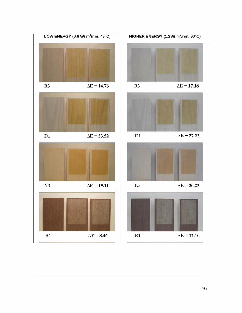
Figure A2. 1: Colour changes for Reconstituted veneers at low irradiance Figure A2. 2 shows the comparison of visual appearances and colour change for selected samples at both high and low irradiance levels. As mentioned earlier in the report, the human eye is sensitive to a ΔE of around 5 units, so these differences between samples are considered not to be significant.
56
LOW ENERGY (0.6 W/ m2/nm, 45°C) HIGHER ENERGY (1.2W/ m2/nm, 60°C)
R5 ∆E = 14.76 R5 ∆E = 17.18
D1 ∆E = 23.52 D1 ∆E = 27.23
N3 ∆E = 19.11 N3 ∆E = 20.23
R1 ∆E = 8.46 R1 ∆E = 12.10

57
Figure A2. 2: Comparison of colour changes for selected unprotected veneers at low and high irradiance levels after 144 h in QUV
D6 ∆E = 7.76 D6 ∆E = 9.87

58
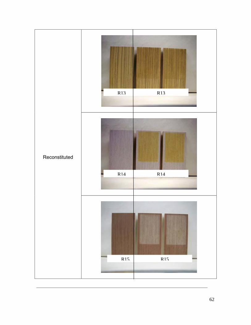
Appendix 3: Pictures of unprotected veneers before and after QUV exposure
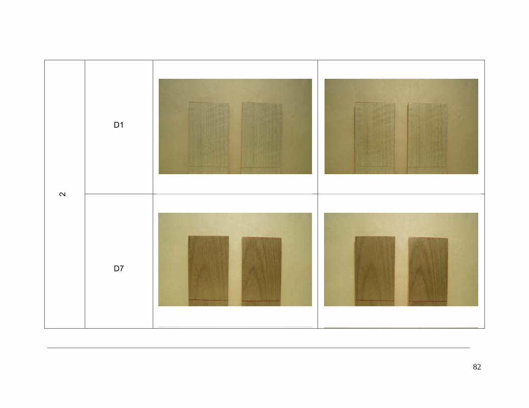
Table A3. 1: Images of unprotected veneer samples at initial time (control sample) and after 144 hours of QUV exposure
Veneer type
Initial time (t = 0 h) After QUV exposure (t = 144 h)
Reconstituted
R1 R1
R2 R2
R3 R3

59
Reconstituted
R4 R4
R5 R5
R6 R6

60
Reconstituted
R9 R9
R8 R8
R7 R7

61
Reconstituted
R12 R12
R11 R11
R10 R10
62
Reconstituted
R13 R13
R14 R14
R15 R15

63
Dyed
D1 D1
D3 D3
D2 D2

64
Dyed
D6 D6
D4 D4
D5 D5

65
Dyed
Natural
D7 D7
D8 D8
N1 N1

66
Natural
N4 N4
N3 N3
N2 N2

67
Appendix 4: Pictures of unprotected veneers before and after QUV exposure
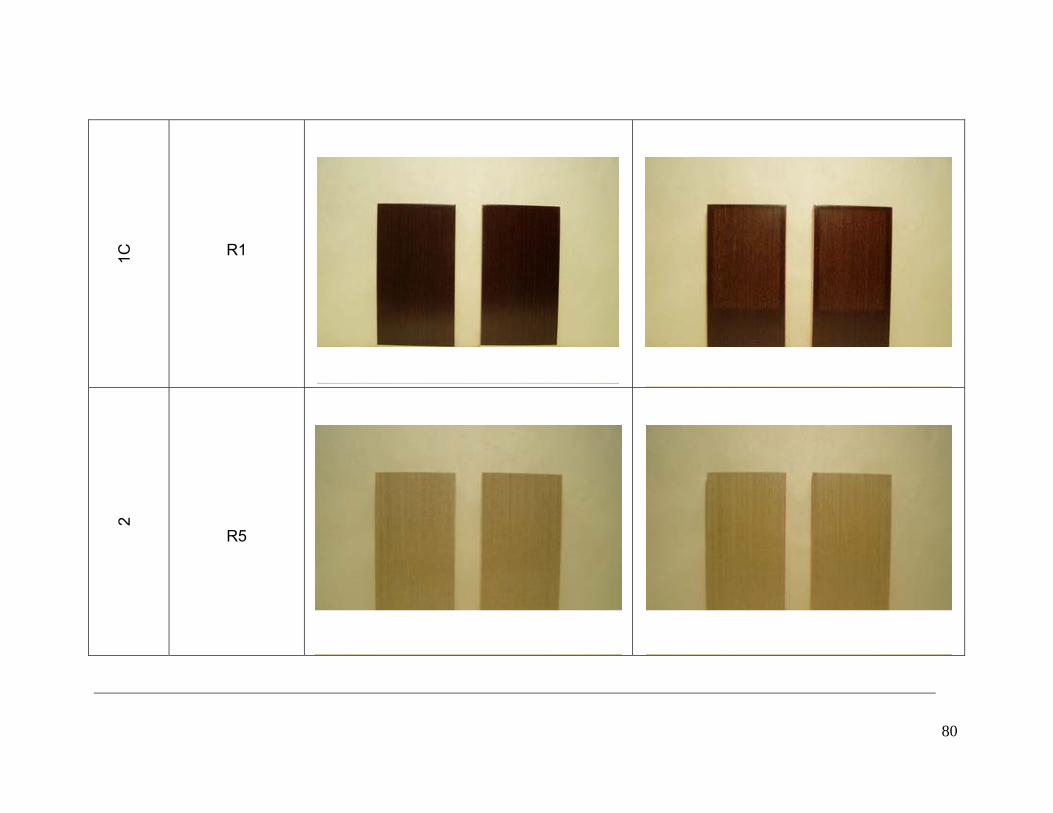
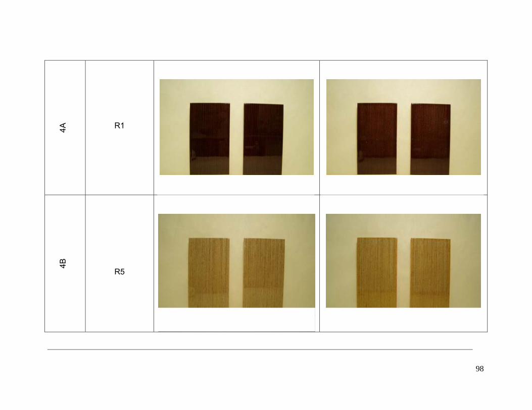
Table A4. 1: Pictures of protected veneer samples at initial time and after 500 hours of QUV exposure
Coating Veneer code Before exposure 500 h exposure
R5
1A
R14

68
R8
1A
D1

69
D7
1A
N3

70
N4
1A
D6

71
1A R1
1B
R5

72
R14
1B
R8

73
D1
1B
D7

74
N3
1B
N4

75
D6
1B
R1

76
R5
1C
R14

77
R8
1C
D1

78
D7
1C
N3

79
N4
1C
D6
80
1C
R1
2
R5

81
R14
2
R8
82
D1
2
D7

83
N3
2
N4

84
D6
2
R1

85
R5
3A
R14

86
R8
3A
D1

87
D7
3A
N3

88
N4
3A
D6

89
3A
R1
3B
R5

90
R14
3B
R8

91
D1
3B
D7

92
N3
3B
N4

93
D6
3B
R1

94
R5
4A
R14

95
R8
4A
D1

96
D7
4A
N3

97
N4
4A
D6
98
4A
R1
4B
R5

99
R14
4B
R8

100
D1
4B
D7

101
N3
4B
N4

102
D6
4B
R1

103
References
1. ASTM G154 (2006) Standard Practice for Operating Fluorescent Light
Apparatus for UV Exposure Of Nonmetalic Materials
2. ASTM G151 (2006) Standard Practice for Exposing Nonmetallic Materials in
Accelerated Test Devices that Use Laboratory Light Sources
3. Q-Panel Lab Products (2004) A Choice of Lamps for the QUV. [WWW]
http://www.q-panel.com/UserFiles/File/PDFs-EN/QUV-Lamp-Types-LU8160-
EN.pdf
4. Chang, S. T., Chou, P.L. (2000) Photodiscoloration Inhibition of Wood
Coated With UV-Curable Acrylic Clear Coatings and Its Elucidation. Polymer
Degradation and Stability, Vol. 69, pp. 355-360.
5. Chang, H. T., Yeh, T. F., Chang, S. T. (2002) Comparisons of Chemical
Characteristic Variations for Photodegraded Softwood and Hardwood
With/Without Polyurethane Clear Coatings. Polymer Degradation and
Stability, Vol. 77, pp. 129-135.
6. Podgorski, L., Arnold, M., Hora, G. (2003) A Reliable Artificial Weathering
Test for Wood Coatings. Coatings World, pp. 39-48.
CSIRO/University of Melbourne Copyright © This document has been prepared for the project sponsor. It may not be cited in the open literature or circulated elsewhere. Whilst the document has been prepared with due diligence and care the contents are subject to change and as such CSIRO / University of Melbourne and its employees are not responsible for the results of any actions taken in reliance on it or for any errors or omissions herein