Embed Size (px)
Citation preview
Mitigating The Impacts of Elevated water Storage Tanks on Water Quality
White Paper
Mitigating the Impacts of Elevated Water Storage Tanks on Water Quality

Mitigating The Impacts of Elevated water Storage Tanks on Water Quality
Copyright Copyright © Stantec Inc. All Rights Reserved. This document may be freely redistributed in its entirety provided that this copyright notice is not removed. This document may not be sold for profit or used in commercial documents without the written permission of the copyright holder. This document is for information purposes only and does not constitute the rendering of professional advice or recommendations by Stantec Inc. All information herein reflects the writer’s professional judgment given the information available at the time of preparation.

Mitigating The Impacts of Elevated water Storage Tanks on Water Quality
Table of Contents
Introduction............................................................................................... 1
Barrhaven Water Pressure Zone.............................................................. 1
Benefits Of Elevated Storage ................................................................... 2
Elevated Tank Design – Improve Internal Mixing..................................... 4
Elevated Tank Operations – Tank Replenishment................................... 5
Summary ................................................................................................ 10
Acknowledgments .................................................................................. 10

Mitigating The Impacts of Elevated water Storage Page 1 of 10 Tanks on Water Quality
Introduction From an operational perspective, elevated water storage tanks are generally considered extremely beneficial to water distribution systems. These “floating” storage tanks reduce peak pumping rates, stabilize pressures, and increase reliability. However, elevated storage can be significantly more costly than in-ground storage (depending on pumping needs) and, if not designed and operated properly, can have a detrimental impact on water quality. As water quality is becoming an increasingly critical factor in water supply and distribution systems, it is crucial that potentially negative water quality impacts from elevated storage be recognized and eliminated.
Water quality in the distribution system has been addressed at both the design and operational stages at the Barrhaven Elevated Water Storage Tank, recently constructed in the City of Ottawa. The goal is to ensure that the overall travel time from the treatment plant to the customer does not increase significantly with the implementation of an elevated tank. This helps ensure that adequate chlorine residuals are maintained at all points in the system. The tank design features include a dual-riser pipe system with check valves to allow for complete mixing of new water with old, thereby eliminating the possibility of stagnation from “dead” areas within the tank bowl. Operational guidelines have also been established to help maintain maximum turnover of water in the tank and to control the replenishment of water in the lengthy feed pipe connecting the tank to the distribution system. Since the feed pipe to this particular tank is over 2700m in length (from the last connection to the distribution system) and is 610mm in diameter, there is a significant volume of water in the pipe at any given time. An analysis was undertaken to confirm that the water volume in both the tank and feed pipe could be effectively replenished with fresh chlorinated water and thus maintain appropriate chlorine residual levels at all times.
This paper will review the design, discuss operational procedures, and explain how water quality issues were addressed for the Barrhaven Elevated Water Storage Tank.
Barrhaven Water Pressure Zone The Barrhaven Pressure Zone is one of eleven (11) major pressure zones in the City of Ottawa’s central water system. It is fed from the Britannia Water Purification Plant through approximately 18km of 1525mm and 1220mm diameter water main. The Barrhaven Pump Station increases the hydraulic grade line (HGL) to feed this zone at appropriate pressures. The Barrhaven Elevated Tank is located at the western extremity of the pressure zone, away from existing development, as shown in Figure 1. A single 610mm water main and a combination of

Mitigating The Impacts of Elevated water Storage Page 2 of 10 Tanks on Water Quality
305mm and 406mm water mains feed the tank from the pump station through the developed area.
The current serviced population in the Barrhaven Pressure Zone is just over 25,000 persons. The maximum day demand for this zone, which consists primarily of low and medium residential development, is approximately 19ML/d and the peak hour demand is close to 40ML/d. By 2021, the population of this area is expected to be close to 90,000 persons, an increase of 360%.
Benefits Of Elevated Storage Water storage is an extremely important element in a water distribution system. The principal advantages of distribution storage is that it can moderate the demands placed on the major supply sources, production works as well as major transmission mains. As a result, the sizes and/or capacities of each of these distribution system elements may be reduced. Additionally, distribution storage normally results in stabilized system pressures. Reserve supplies of water in distribution storage also provide a redundant source of water during emergencies, such as fires; water main breaks, and pump station power outages. The major purposes of storage are summarized as:
• Operational equalization (balancing storage)
• Fire flow provision
• Emergency needs
Figure 1: Barrhaven Tank – General Location

Mitigating The Impacts of Elevated water Storage Page 3 of 10 Tanks on Water Quality
There are two types of distribution storage. These are in-ground (or at-grade) reservoirs and elevated storage tanks. Generally, elevated storage tanks have been limited to a volume of approximately 9.0ML, whereas in-ground reservoirs are not limited in volume. In-ground reservoirs may utilize either a direct pumping system (which requires a pumping system to pump water from the reservoir to system pressures) or an indirect pumping system (water “floats” on the system and flows by gravity from the tank to system pressures). Elevated storage tanks are virtually always indirect systems and float at the connected system HGL.
The indirect pumping system (with floating or elevated storage) has several advantages over a direct pumping system in a water distribution system:
• Lowering peak pumping rates
• Stabilizing pressure variations as demands fluctuate
• Maintains constant, reliable water supply and pressures
• Increased operational flexibility, efficiency and convenience
• Balancing and leveling pump operations
• Reduces need for wide range of pump sizes
• Decreasing power costs – particularly for “time-of-day” energy pricing
• Immediate emergency response (main break, power failure)
• Immediate fire flow and pressure response
• Surge relief – dampens extreme low and high low pressures associated with hydraulic transients
• Ensures constant system pressure and helps prevent contamination from possible inflow
Based on the above, it is thus evident that distribution system storage is extremely beneficial to a water supply system. In particular, storage with indirect pumping (i.e. floating storage) provides clear advantages to the operation of the system and should thus be considered whenever and wherever practical and feasible.
The major disadvantage with any distribution storage is the possibility of increased travel time from the treatment plant (chlorination point) “to the tap”. Ensuring adequate replenishment of water in storage facilities is a key factor in minimizing the potential chorine decay in the treated water. Two factors may be considered to improve this – ensuring good mixing of fresh water with stored water in the tank and ensuring that the system is operated to maximize the replenishment of fresh water in the tank. It is noted that in-tank mixing is preferred for smaller tank volumes – “plug” flow may be preferred to ensure adequate water turnover in larger tanks.

Mitigating The Impacts of Elevated water Storage Page 4 of 10 Tanks on Water Quality
As such, a review of the potential impact of the Barrhaven Elevated Water Storage Tank on water quality has been undertaken to determine any special measures or operating procedures should be followed after the tank is commissioned.
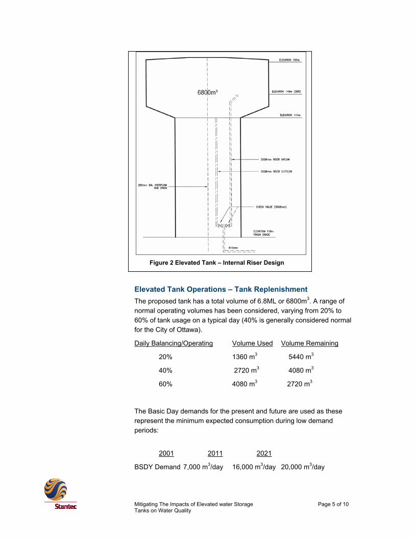
Elevated Tank Design – Improve Internal Mixing To improve mixing of fresh water with “old” water inside the tank bowl, a two-riser pipe system with check valves has been incorporated in the design. This is shown schematically in Figure 2. The check valves ensure the tank fills through only one of the risers and is drawn down through the second riser pipe. The top of the “fill” riser pipe is angled to promote circulation in the tank and minimize the opportunity for “short-circuiting” of flow in the bowl.
The fill riser pipe will extend into the bowl of the tank to approximately 300mm below the minimum level of the normal operating range. The draw riser pipe will be located at the base of the bowl. A series of check valves will be used to ensure that the proper riser pipe is used for either filling or drawing. Each riser pipe will have a diameter of 600mm and will be insulated. A 400mm diameter overflow pipe will also be located in the structure to ensure that the maximum water level is never exceeded.
Valves located in the control room will consist of a check valve for the fill riser pipe, a check valve for the draw riser pipe, a main shutoff valve and shutoff valve to form a drain connection between the overflow and the draw riser pipe. This drain connection will allow for the tank to be emptied via the overflow pipe outlet. A chemical feed nozzle will also be included on the drainpipe to allow for dechlorination during the emptying of the tank. It is also proposed to add two additional valves and couplings on the fill riser pipe and the draw riser pipe to allow for a future re-circulation pump, should one be required.
Mitigating The Impacts of Elevated water Storage Page 5 of 10 Tanks on Water Quality
Elevated Tank Operations – Tank Replenishment The proposed tank has a total volume of 6.8ML or 6800m3. A range of normal operating volumes has been considered, varying from 20% to 60% of tank usage on a typical day (40% is generally considered normal for the City of Ottawa).
Daily Balancing/Operating Volume Used Volume Remaining
20% 1360 m3 5440 m3
40% 2720 m3 4080 m3
60% 4080 m3 2720 m3
The Basic Day demands for the present and future are used as these represent the minimum expected consumption during low demand periods:
2001 2011 2021
BSDY Demand 7,000 m3/day 16,000 m3/day 20,000 m3/day
Figure 2 Elevated Tank – Internal Riser Design
Mitigating The Impacts of Elevated water Storage Page 6 of 10 Tanks on Water Quality
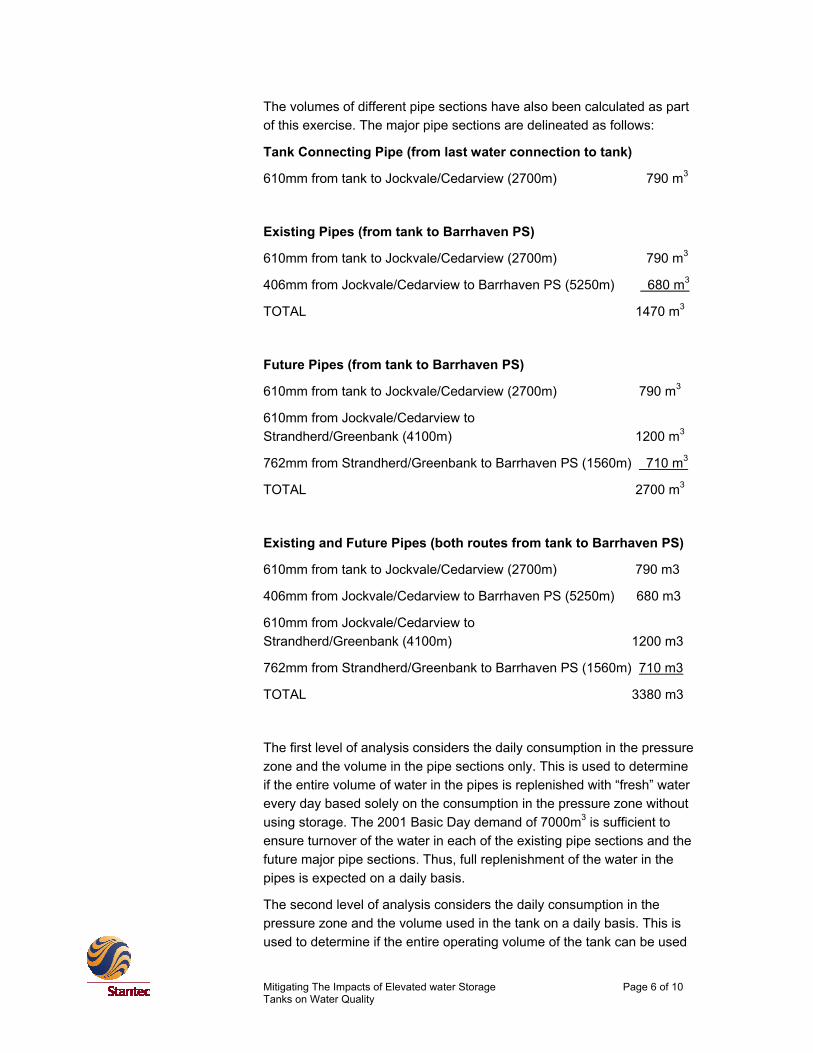
The volumes of different pipe sections have also been calculated as part of this exercise. The major pipe sections are delineated as follows:
Tank Connecting Pipe (from last water connection to tank)
610mm from tank to Jockvale/Cedarview (2700m) 790 m3
Existing Pipes (from tank to Barrhaven PS)
610mm from tank to Jockvale/Cedarview (2700m) 790 m3
406mm from Jockvale/Cedarview to Barrhaven PS (5250m) 680 m3
TOTAL 1470 m3
Future Pipes (from tank to Barrhaven PS)
610mm from tank to Jockvale/Cedarview (2700m) 790 m3
610mm from Jockvale/Cedarview to Strandherd/Greenbank (4100m) 1200 m3
762mm from Strandherd/Greenbank to Barrhaven PS (1560m) 710 m3
TOTAL 2700 m3
Existing and Future Pipes (both routes from tank to Barrhaven PS)
610mm from tank to Jockvale/Cedarview (2700m) 790 m3
406mm from Jockvale/Cedarview to Barrhaven PS (5250m) 680 m3
610mm from Jockvale/Cedarview to Strandherd/Greenbank (4100m) 1200 m3
762mm from Strandherd/Greenbank to Barrhaven PS (1560m) 710 m3
TOTAL 3380 m3
The first level of analysis considers the daily consumption in the pressure zone and the volume in the pipe sections only. This is used to determine if the entire volume of water in the pipes is replenished with “fresh” water every day based solely on the consumption in the pressure zone without using storage. The 2001 Basic Day demand of 7000m3 is sufficient to ensure turnover of the water in each of the existing pipe sections and the future major pipe sections. Thus, full replenishment of the water in the pipes is expected on a daily basis.
The second level of analysis considers the daily consumption in the pressure zone and the volume used in the tank on a daily basis. This is used to determine if the entire operating volume of the tank can be used

Mitigating The Impacts of Elevated water Storage Page 7 of 10 Tanks on Water Quality
every day for consumption only in the pressure zone without using pumping. The 2001 Basic Day demand (7000m3/day) is greater than the expected daily operating volumes of the tank under all circumstances. Thus, the full operating volume of water from the tank can be consumed in the system regardless of how the tank is operated.
The third level considers the amount of water remaining in storage (for different operating conditions) and the volume of water in the pipe section between the tank and the last water connection. In this case, the “last” connection is considered to be that at the intersection of Jockvale and Cedarview, which is considered conservative since there is a feed off this pipe to the developed lands northwest of Fallowfield and Cedarview. This assessment is used to determine approximately how much volume in the tank is refilled with fresh water on a daily basis, as opposed to “old” water (“old” water being the un-used volume in the tank plus the amount in the final pipe section between the tank and the last connection, which equals the total amount of “old” water in the tank after refilling).
Daily Balancing Use Fresh Water Volume Fresh Water In Tank (daily)
20% 1360 – 790 = 570 m3 8 %
40% 2720 – 790 = 1930 m3 28 %
60% 4080 – 790 = 3290 m3 48 %
To determine the potential impact on water quality given varying amounts of “fresh” water in the tank resulting from varying the amount of storage used on a daily basis, curves were developed to show the net chlorine residual after a given period of time. These curves, which are based on a chlorine decay rate of 0.1mg/L per day, are shown in Figure 3 and suggest the following:
• If the storage is operated at 20% balancing per day, the net chlorine residual in the tank will continuously decay to eventual depletion.
• If the storage is operated at 40% balancing per day, the net chlorine residual in the tank will level off after about 7 days and will have depleted by about 0.25 mg/L.
• If the storage is operated at 60% balancing per day, the net chlorine residual in the tank will level off after about 5 days and will have depleted by about 0.11 mg/L.
• The rate and magnitude of the depletion is constant, regardless of the incoming “fresh” water chlorine concentration. For

Mitigating The Impacts of Elevated water Storage Page 8 of 10 Tanks on Water Quality
example, if “fresh” water enters the tank at a concentration of 0.75mg/L, the long-term chlorine concentration in the tank, if operated at 40% balancing, will be approximately 0.5mg/L.
• To maintain a reasonable chlorine residual in the tank in the long term, it must be operated with more than 20% of the total volume being used on a daily basis. As expected, the more water that is moved through the tank in a single day, the higher the chlorine residual in the tank.
Net Chlorine Residual@ 0.1mg/L Decay per Day
0.0
0.1
0.2
0.3
0.4
0.5
0.6
0.7
0.8
0.9
1.0
1 3 5 7 9 11 13 15 17 19 21 23 25 27 29 31
Days
Con
cent
ratio
n (m
g/L)
20% Balancing40% Balancing60% Balancing
Figure 3: Net Chlorine Residual – Constant Decay
Figure 4 indicates the residual chlorine level if it is assumed that that chlorine decays at a constant 10% per day (provided for comparative purposes only). At 40% balancing storage operations, the long-term chlorine residual is expected to drop by 20% under this scenario.
The results presented herein were derived from a conservative analysis of the Barrhaven Tank and associated distribution system. The purpose of this high level analysis is to provide some insight as to how water quality is generally affected by the tank size based on various modes of operation.
The analysis assumed there was complete mixing in the tank and that the physical characteristics of the water remained unchanged, such as pH and temperature. A constant chlorine decay rate of 0.1 mg/L per day was used. The analysis also assumed plug flow condition in the pipes, and no water demand to the west of the tank. It should also be noted that the analysis does not reflect the water quality at the customer’s tap because of further mixing of the water from the tank in the water distribution system before it reaches the customer. Therefore it is

Mitigating The Impacts of Elevated water Storage Page 9 of 10 Tanks on Water Quality
expected that the pipes will be maintained at higher chlorine residuals than that in the tank.
Figure 4 indicates the residual chlorine level if it is assumed that that chlorine decays at a constant 10% per day (provided for comparative purposes only). At 40% balancing storage operations, the long-term chlorine residual is expected to drop by 20% under this scenario.
The results presented herein were derived from a conservative analysis of the Barrhaven Tank and associated distribution system. The purpose of this high level analysis is to provide some insight as to how water quality is generally affected by the tank size based on various modes of operation.
The analysis assumed there was complete mixing in the tank and that the physical characteristics of the water remained unchanged, such as pH and temperature. A constant chlorine decay rate of 0.1 mg/L per day was used. The analysis also assumed plug flow condition in the pipes, and no water demand to the west of the tank. It should also be noted that the analysis does not reflect the water quality at the customer’s tap because of further mixing of the water from the tank in the water distribution system before it reaches the customer. Therefore it is expected that the pipes will be maintained at higher chlorine residuals than that in the tank.
Net Chlorine Residual@ 10% Decay per Day
0.0
0.1
0.2
0.3
0.4
0.5
0.6
0.7
0.8
0.9
1.0
1 3 5 7 9 11 13 15 17 19 21 23 25 27 29 31
Days
Con
cent
ratio
n (m
g/L)
20% Balancing40% Balancing60% Balancing
Figure 4 : Net Chlorine residual – Recent Decay

Mitigating The Impacts of Elevated water Storage Page 10 of 10 Tanks on Water Quality
Summary Elevated water storage tanks can be extremely beneficial to water distribution systems operations. These “floating” storage tanks reduce peak pumping rates, stabilize pressures, and increase reliability. It is, however, extremely important that potentially negative water quality impacts from storage be recognized and eliminated.
To help minimize potential water quality degradation, simple tank design features should be considered along with specific operational procedures. Recommended tank design features, which will help promote complete mixing of fresh water with “old” water in the tank and eliminate the possibility of stagnation from “dead” areas within the tank bowl, include:
• Dual-riser pipe system with check valves,
• Angled inflow riser stem.
• Operational procedures should consider water quality, and should include:
• Maximize fresh water turnover (operate tank to lowest level possible),
• Consider tank volume as well as supply piping in water quality analysis.
Acknowledgments John D. Krug, P.Eng., Stantec Consulting Ltd.
Ziad Ghadban, P.Eng., City of Ottawa