Embed Size (px)
Citation preview

Mission Overview SLC-41Cape Canaveral Air Force Station, FL
Mission OverviewU.S. Airforce
Jim Sponnick
Vice President,
Mission Operations
1
Atlas V AEHF-1
United Launch Alliance (ULA) is proud to be a part of the deployment of the U.S. Navy’s Mobile User Objective System (MUOS) satellite constellation.
The MUOS-1 satellite is the ! rst of a ! ve-satellite constellation to be launched and operated by the Navy’s Communications Satellite Program Of! ce, PMW 146. MUOS is the next-generation narrowband tactical satellite communications system designed to signi! cantly improve ground communications to U.S. forces on the move around the globe.
MUOS will fully support legacy UHF SATCOM terminals and Joint Tactical Radio System terminals, ensuring its users receive the technological advancements needed without a gap during necessary system upgrades. The MUOS constella-tion will also provide enhanced geo-location capabilities.
The ULA team is focused on attaining Perfect Product Delivery for the MUOS-1 mission, which includes a relentless focus on mission success (the perfect product) and also excellence and continuous improvement in meeting all of the needs of our customers (the perfect delivery).
Thank you to the entire ULA team and to our mission partners. Your dedication has made this game-changing mission possible.
Go Atlas, Go Centaur, Go MUOS!

Atlas V MUOS-12
MUOS-1 SATELLITE | Overview
The MUOS-1 satellite will ensure continued mission capability of the existing Ultra-High Frequency
Satellite Communications (UHF SATCOM) system, and represents deployment of the ! rst satellite
in the next-generation narrowband tactical satellite communications system which will provide sig-
ni! cantly improved and assured communications for the mobile war! ghter. MUOS-1 will ultimately
replace the current UHF SATCOM system, providing military users with 10 times more communi-
cations capability over existing systems, including simultaneous voice (full-duplex), video and data,
leveraging 3G mobile communications technology.
The Mobile User Objective System will provide Net-Centric use of UHF SATCOM and provides the
following enabling capabilities:
• Beyond-line-of-site, communication-on-the-move to the war! ghter with focus on usability.
• Global communications to connect any set of users, regardless of location with the
exception of polar regions.
• Improved connectivity in stressed environments including urban canyons, mountains, jungle,
weather and scintillation.
• “Bandwidth on Demand” architecture that is future upgradeable with “smarts” on the ground
and has accessibility to Global Information Grid (GIG), Non-secure Internet Protocol
Router Network (NIPRNet), Secure Internet Protocol Router Network (SIPRNet), and Defense
Information Systems Network (DISN).
3Image courtesy of Lockheed Martin Corporation

5-mPayloadFairing
Launch VehicleAdapter
Space VehicleAdapter
Atlas V Booster
Solid RocketBoosters
RD-180Engine
MUOS-1Satellite
Centaur
Boattail
CentaurInterstageAdapterBooster
CylindricalInterstageAdapter
Forward LoadReactor (FLR)
RL10A CentaurEngine
4
ATLAS V 551 LAUNCH VEHICLE | Overview
The Atlas V 551 consists of a single Atlas V booster stage, the Centaur upper stage, ! ve solid
rocket boosters (SRB) and a 5-m diameter medium payload fairing (PLF).
The Atlas V booster is 12.5 ft in diameter and 106.5 ft in length. The booster’s tanks are
structurally rigid and constructed of isogrid aluminum barrels, spun-formed aluminum domes, and
intertank skirts. Atlas booster propulsion is provided by the RD-180 engine system (a single
engine with two thrust chambers). The RD-180 burns RP-1 (Rocket Propellant-1 or highly
puri! ed kerosene) and liquid oxygen, and delivers 860,200 lb of thrust at sea level. The Atlas V
booster is controlled by the Centaur avionics system, which provides guidance, " ight control, and
vehicle sequencing functions during the booster and Centaur phases of " ight.
The SRBs are approximately 61 in. in diameter, 67 ft in length and constructed of a graphite-ep-
oxy composite with the throttle pro! le designed into the propellant grain. The SRBs are jettisoned
by structural thrusters following a 92-second burn.
The Centaur upper stage is 10 ft in diameter and 41.5 ft in length. Its propellant tanks are
constructed of pressure-stabilized, corrosion resistant stainless steel. Centaur is a liquid hydrogen/
liquid oxygen- (cryogenic-) fueled vehicle. It uses a single RL10A-4-2 engine producing
22,300 lb of thrust. The Centaur forward adapter (CFA) provides the structural mountings for
vehicle electronics and the structural and electronic interfaces with the satellite.
The MUOS-1 satellite is encapsulated in the Atlas V 5-m diameter medium PLF. The PLF is a
sandwich composite structure made with a vented aluminum-honeycomb core and graphite-
epoxy face sheets. The bisector (two-piece shell) PLF encapsulates both the Centaur and the
spacecraft, which separates using a debris-free pyrotechnic actuating system. Payload clearance
and vehicle structural stability are enhanced by the all-aluminum Centaur forward load reactor
(CFLR), which centers the PLF around the Centaur upper stage and shares payload shear loading.
The vehicle’s height with the 5-m medium PLF is approximately 206 ft.
5
ATLAS V 551 LAUNCH VEHICLE | Expanded View
Atlas V MUOS-1

Atlas V MUOS-1
VIF
3
4
1
6
7
8
9 10
11
12
4 5
32
SPACE LAUNCH COMPLEX 41 (SLC-41) | Overview
1 Vertical Integration Facility (VIF) (See inset)
2 Bridge Crane Hammerhead
3 Bridge Crane
4 Launch Vehicle
5 Mobile Launch Platform (MLP)
6 6 LaLaununchch V Vehehiciclele
7 7 CeCentntauaur r LOLO2 2 StStororagagee
8 8 GaGaseseouous s HeHeliliumum C Cononveversrsioion n PlPlanantt
9 9 HiHighgh P Preressssurure e GaGas s StStororagagee
10 Booster LO2 Storage
11 Pad ECS Shelter
12 Pad Equipment Building (PEB)
6
ATLAS V MUOS-1 | Mission Overview
7
The MUOS-1 mission is based on an Atlas V 551 ascent pro! le to geosynchronous transfer orbit
(GTO). The mission begins with ignition of the RD-180 engine at approximately 2.7 seconds
prior to liftoff. The " ight begins with a vertical rise of 85 feet, after which the vehicle begins its
initial pitch-over phase, a roll, pitch, and yaw maneuver to achieve the desired " ight azimuth. The
vehicle then throttles down and begins a nominal zero pitch and zero yaw angle-of-attack phase
to minimize aerodynamic loads. Following maximum dynamic pressure and SRB burnout, the RD-
180 is throttled back up to 100 percent. Zero pitch and yaw angle-of-attack " ight continues until
closed-loop guidance takes over at approximately 110 seconds into " ight.
Booster " ight continues in this guidance-steered phase until propellant depletion. Payload fairing
jettison occurs at approximately 202 seconds, based on thermal constraints. When the vehicle
reaches 4.6 Gs the RD-180 engine is throttled to maintain this G-level. The boost phase of " ight
ends with Atlas/Centaur separation at a nominal time of 6.0 seconds after Booster Engine Cutoff
(BECO).
Following Atlas/Centaur separation, the Centaur stage ignites its main engine or Main Engine Start
1 (MES-1). The 462-second Centaur ! rst burn concludes with Main Engine Cutoff 1 (MECO-1),
injecting the vehicle into a low-Earth parking orbit.
Following MECO-1, the Centaur and spacecraft (SC) enter an 8.4-minute coast period. Based on
a guidance-calculated start time, the Centaur is re-started (MES-2) then steered into an interme-
diate transfer orbit. The second Centaur burn duration is 361 seconds and concludes with Main
Engine Cutoff (MECO-2), initiated by guidance command once the targeted orbital parameters
are achieved.
The Centaur and spacecraft next enter a 2.5-hour coast period. Based on a guidance-calculated
start time, the Centaur is re-started (MES-3) then steered into the spacecraft separation transfer
orbit. The third Centaur burn duration is 54 seconds and concludes with Main Engine Cutoff
(MECO-3), initiated by guidance command once the targeted orbital parameters are achieved.
Spacecraft separation is initiated 219 seconds after MECO-3, at 3 hours, 1 minute, 23.2 sec-
onds after liftoff.
Atlas V MUOS-18
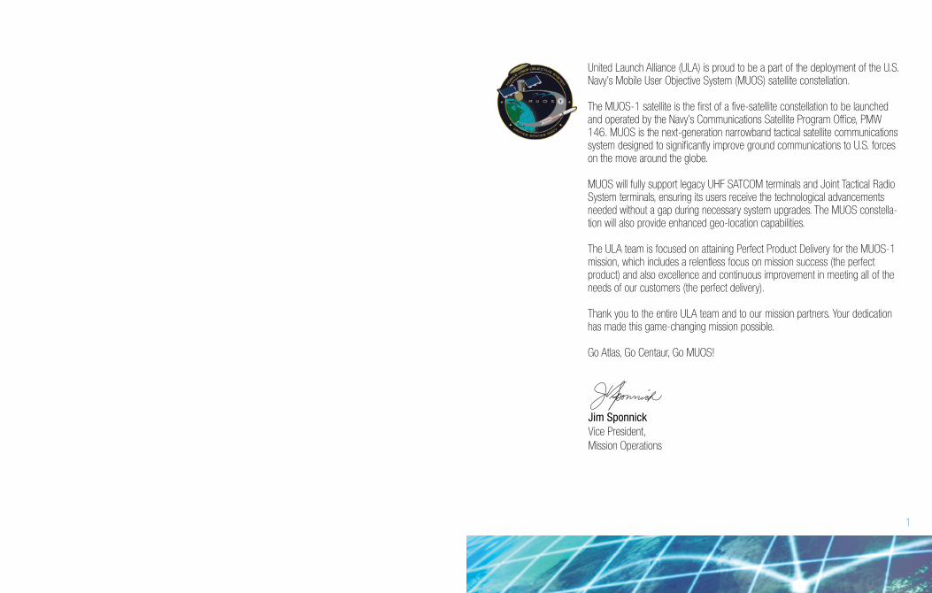
FLIGHT PROFILE | Liftoff to Spacecraft Separation
9
SEQUENCE OF EVENTS | Liftoff to Spacecraft Separation
Time(seconds)Event
Time(hr:min:sec)
RD-180 Engine Ignition
T=0 (Engine Ready)
Liftoff (Thrust to Weight > 1)
Full Thrust
Begin Pitch/Yaw/Roll Maneuver
Mach 1
Maximum Dynamic Pressure
Solid Rocket Booster 1,2 Jettison
Solid Rocket Booster 3,4,5 Jettison
Payload Fairing Jettison
Centaur Forward Load Reactor Jettison
Begin 4.6 G-Limiting
Atlas Booster Engine Cutoff (BECO)
Atlas Booster/Centaur Separation
Centaur First Main Engine Start (MES-1)
Centaur First Main Engine Cutoff (MECO-1)
Centaur Second Main Engine Start (MES-2)
Centaur Second Main Engine Cutoff (MECO-2)
Centaur Third Main Engine Start (MES-3)
Centaur Third Main Engine Cutoff (MECO-3)
Spacecraft Separation
-0:00:02.7
0:00:00
0:00:01.1
0:00:02.1
0:00:03.9
0:00:34.8
0:00:45.2
0:01:44.6
0:01:46.1
0:03:22.2
0:03:50.0
0:03:50.0
0:04:24.1
0:04:30.1
0:04:40.1
0:12:21.0
0:20:48.9
0:26:50.1
2:56:50.4
2:57:44.2
3:01:23.2
-2.7
0.0
1.1
2.1
3.9
34.8
45.2
104.6
106.1
202.2
207.2
230.0
264.1
270.1
280.1
741.0
1,248.9
1,610.1
10,610.4
10,664.2
10,883.2
1
2
3
4
6
7
8
5
8
Approximate Values
Orbit at SC Separation:
Apogee Altitude: 35,786.6 km (19,323.2 nmi)
Perigee Altitude: 3,462.9 km (1,869.8 nmi)
Inclination: 19.0°
Argument of Pergiee: 179.0°
1
2
3
4
5 6 7 8
10
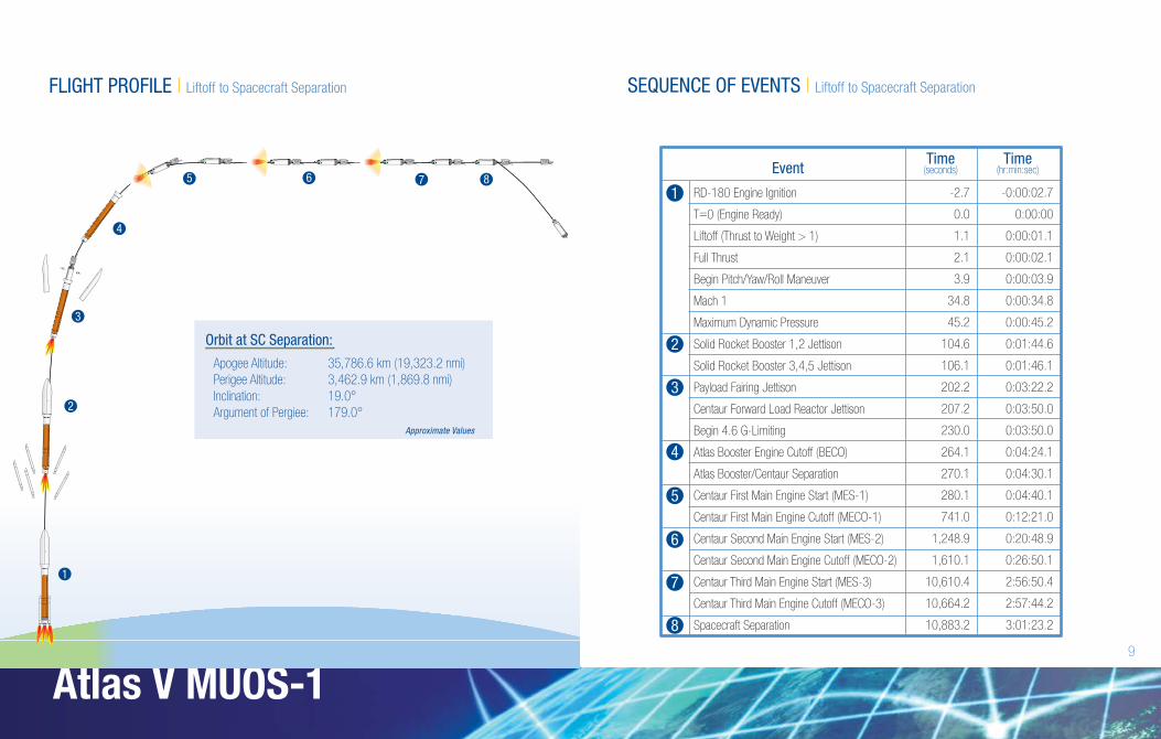
Harlingen, TX
• Payload Adapter Fabrication
• Booster Adapter Fabrication
• Centaur Adapter Fabrication
Cape Canaveral Air Force Station, FL
• Payload Processing & Encapsulation
• Launch Vehicle Processing
• Encapsulated Payload Mating
• Launch
Decatur, AL
• Booster Fabrication & Final Assembly
• Centaur Final Assembly
tation, FLSacramento, CA
• Solid Rocket Booster Fabrication
at Aerojet
San Diego, CA
• Centaur Tank Fabrication
Denver, CO
• ULA Headquarters &
Design Center Engineering
Zurich, Switzerland
• 5-m Payload Fairing
Fabrication at RUAG Space
d
pace
Khimki, Russia
• RD-180 Engine Fabrication
at NPO Energomash
cationion
West Palm Beach, FL
• RL10 Engine Fabrication
at Pratt & Whitney
ricationFabricrication
stWest
L10• RL10
Pra at Pra
ATLAS V PRODUCTION & LAUNCH | Overview ATLAS V PROCESSING | Cape Canaveral
11
Atlas V MUOS-1
Vertical Integration
FacilityIntegrate,
Spacecraft Mate,Test
Solid RocketBoosters
Booster
Spacecraft SLC-41 Test & Launch
Mobile Launch Platform
SpacecraftProcessing Facility
Test, Encapsulate
PayloadTransporter
Antonov AN-124
Centaur
Antonov AN-124
5-m PayloadFairing Halves
InterstageAdapters
Receiving & Inspection VIP ViewingLaunch Control Center Of!cesCommunication Center Mission Director’s CenterBattery Lab Spacecraft Control RoomAdministrative Of!ces ITAR FacilityMaterial Stores Conference Center
Atlas Space!ight Operations Center (ASOC)
12
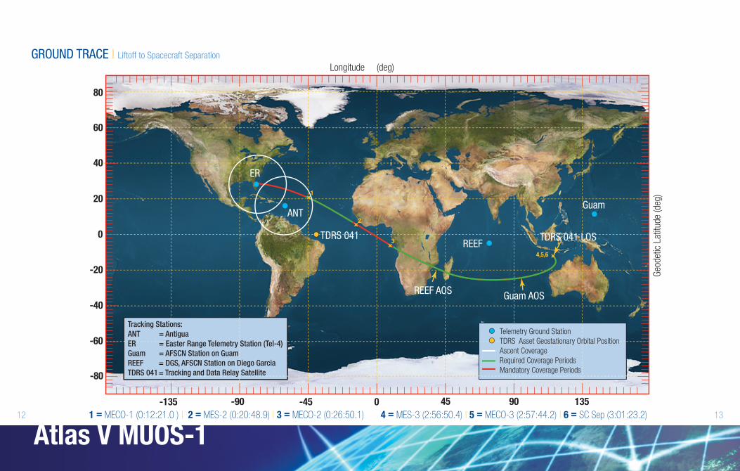
GROUND TRACE | Liftoff to Spacecraft Separation
13
Atlas V MUOS-1
Longitude (deg)
Geo
det
ic L
atitu
de
(deg
)
80
60
40
20
0
-20
-80
-60
-40
-135 -90 -45 0 1359045
Tracking Stations:
ANT = Antigua
ER = Easter Range Telemetry Station (Tel-4)
Guam = AFSCN Station on Guam
REEF = DGS, AFSCN Station on Diego Garcia
TDRS 041 = Tracking and Data Relay Satellite
1 = MECO-1 (0:12:21.0 ) | 2 = MES-2 (0:20:48.9) | 3 = MECO-2 (0:26:50.1) 4 = MES-3 (2:56:50.4) | 5 = MECO-3 (2:57:44.2) | 6 = SC Sep (3:01:23.2)
Longitude (deg)
Geo
detic
Lat
itude
(de
g)
Telemetry Ground Station
TDRS Asset Geostationary Orbital Position
Ascent Coverage
Required Coverage Periods
Mandatory Coverage Periods
ER
ANT
TDRS 041 TDRS 041 LOS
1
REEF
REEF AOSGuam AOS
Guam
3
4,5,6
2

COUNTDOWN TIMELINE | Launch-1 Day
Launch-1 Day MLP TRANSPORT TO PAD
Flight Control Preps
7:30 a.m. 8:00 a.m. 9:00 a.m. 10:00 a.m. 11:00 a.m. 12:00 p.m. 1:00 p.m. 2:00 p.m. 3:00 p.m. 4:00 p.m.
Transport Preps Pad Connections
Transport Preps Pneumatic System Preps
MLP Transport Preps MLP Roll MLP Connect
MLP Hard Down
Ground Command
Control Comm.,
Radio Frequency/
Flight Termination
System
Atlas/Centaur
Pneumatics &
Propulsion
Environmental
Control System,
Flight Control
WeatherBrief
StatusCheck
WeatherBrief
StatusCheck
14 15
Atlas V MUOS-1

COUNTDOWN TIMELINE | Launch Day
Launch Day
Weather Brief
T-02:00
Open Loop Test & Monitor Preps
Power Application, System Preps,
Flight Control/Guidance Tests & Countdown Preps
Centaur LH2/LO2 Preps Atlas
Propulsion/Hydraulic Preps Storage Area Chilldown
T-01:00 T-00:45 T-00:30 T-00:15 T-00:04
Flight Control
Final Preps
PressurizeChilldown &
Tanking
T-0
:04
(T-4
min
ute
s)
& H
old
ing
Status Check
T-03:00T-04:00T-05:00T-06:00T-06:20
StartCount
Flight Control
Environmental Control System GN2 Preps
Open/Closed Loop Tests
All Systems on GN2
StatusCheck
WeatherBrief
LAUNCH
Ground Command
Control Comm.,
Radio Frequency/
Flight Termination
System
Atlas/Centaur
Pneumatics &
Propulsion
Environmental
Control System
(HH:MM)
16 17
Atlas V MUOS-1
United Launch Alliance | P.O. Box 3778 Centennial, CO 80155-3788 | www.ulalaunch.com
Copyright © 2012 United Launch Alliance, LLC. All Rights Reserved. Atlas is a Registered Trademark of Lockheed Martin Corporation. Used with Permission.


![[Coming Soon] - El Canaveral](https://img.dokumen.tips/doc/110x75/61a1cf50f7f42135a9318292/coming-soon-el-canaveral.jpg)