Embed Size (px)
Citation preview
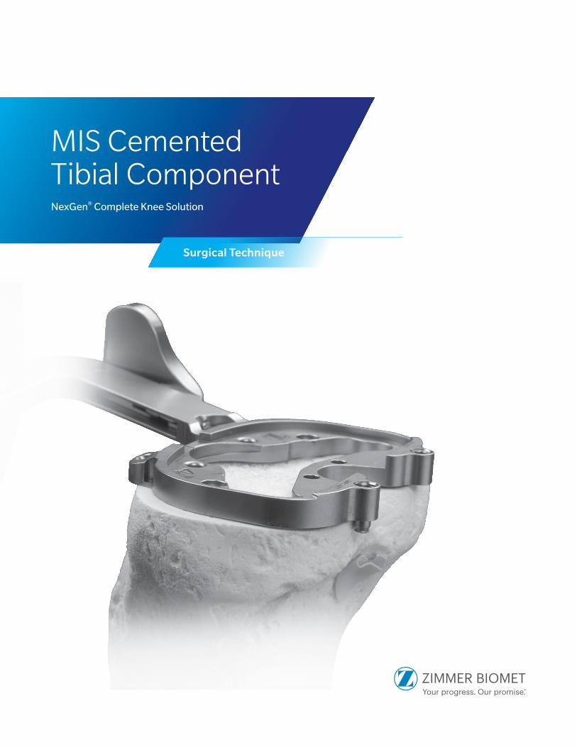
MIS Cemented Tibial ComponentNexGen® Complete Knee Solution
Surgical Technique

Table of Contents
Surgical Exposure ..................................................................................................... 2
Finish the Tibia .......................................................................................................... 2
Position Based on Anatomic Landmarks .................................................................. 3 Lateral Posterior Hook Medial Posterior Hook No Posterior Hooks
Position Based on Trial Range of Motion .................................................................. 6
MIS Tibial Component Preparation without Stem Extension .................................. 8
MIS Tibial Component Preparation with Drop Down Stem Extension .................. 11
Implant Components .............................................................................................. 15 MIS Tibial Component with MIS Drop Down Extension
Technique for MIS Flex Bearing Locking Screw ...................................................... 20
2 | NexGen MIS Cemented Tibial Component Surgical Technique
Figure 1
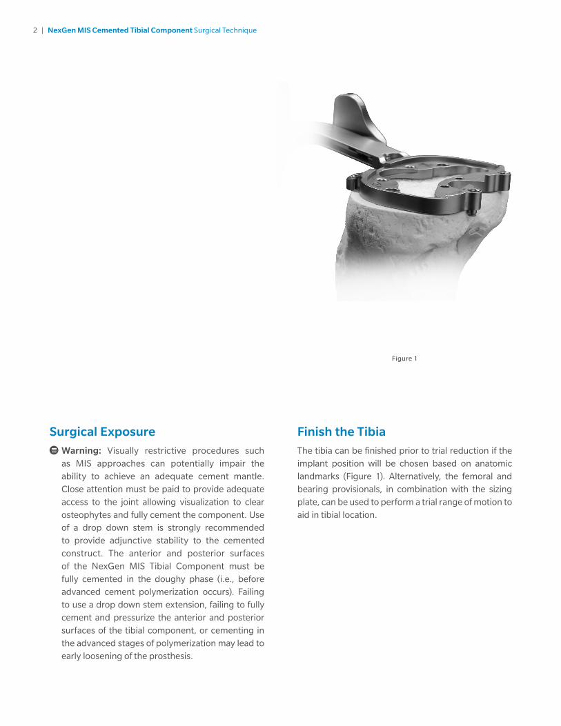
Finish the TibiaThe tibia can be finished prior to trial reduction if the implant position will be chosen based on anatomic landmarks (Figure 1). Alternatively, the femoral and bearing provisionals, in combination with the sizing plate, can be used to perform a trial range of motion to aid in tibial location.
Surgical Exposure
Warning: Visually restrictive procedures such as MIS approaches can potentially impair the ability to achieve an adequate cement mantle. Close attention must be paid to provide adequate access to the joint allowing visualization to clear osteophytes and fully cement the component. Use of a drop down stem is strongly recommended to provide adjunctive stability to the cemented construct. The anterior and posterior surfaces of the NexGen MIS Tibial Component must be fully cemented in the doughy phase (i.e., before advanced cement polymerization occurs). Failing to use a drop down stem extension, failing to fully cement and pressurize the anterior and posterior surfaces of the tibial component, or cementing in the advanced stages of polymerization may lead to early loosening of the prosthesis.

3 | NexGen MIS Cemented Tibial Component Surgical Technique
Figure 2 Figure 3
Lateral Posterior Hook
Deploy the posterior hook that corresponds to the lateral side of the tibia using the small hexhead screwdriver (Figure 2).
Purpose: Placing the posterior hook behind the lateral side of the tibia provides an anchor on anatomy for incisions on the medial side. The sizing plate can then be rotated on the medial side until proper rotational alignment is achieved (Figure 3).
Consideration: The A/P dimension of the proximal tibia is generally larger on the medial side compared to the lateral side. When the sizing plate is positioned correctly in rotation, there could be a tendency to slightly underhang the tibia on the posteromedial edge.
Position Based on Anatomic LandmarksPosterior hooks on the lateral and medial side of the sizing plate can be deployed to aid in size selection and positioning of the MIS tibial sizing plate.
There are several options available for use of the posterior hooks during sizing plate selection and positioning. The surgeon can decide which option is appropriate depending on patient anatomy or incision size, as well as whether a medial or lateral incision is used. Make sure that the posterior edge of the tibia is free of osteophytes and soft tissues which could interfere with the proper positioning of the posterior hooks.
4 | NexGen MIS Cemented Tibial Component Surgical Technique
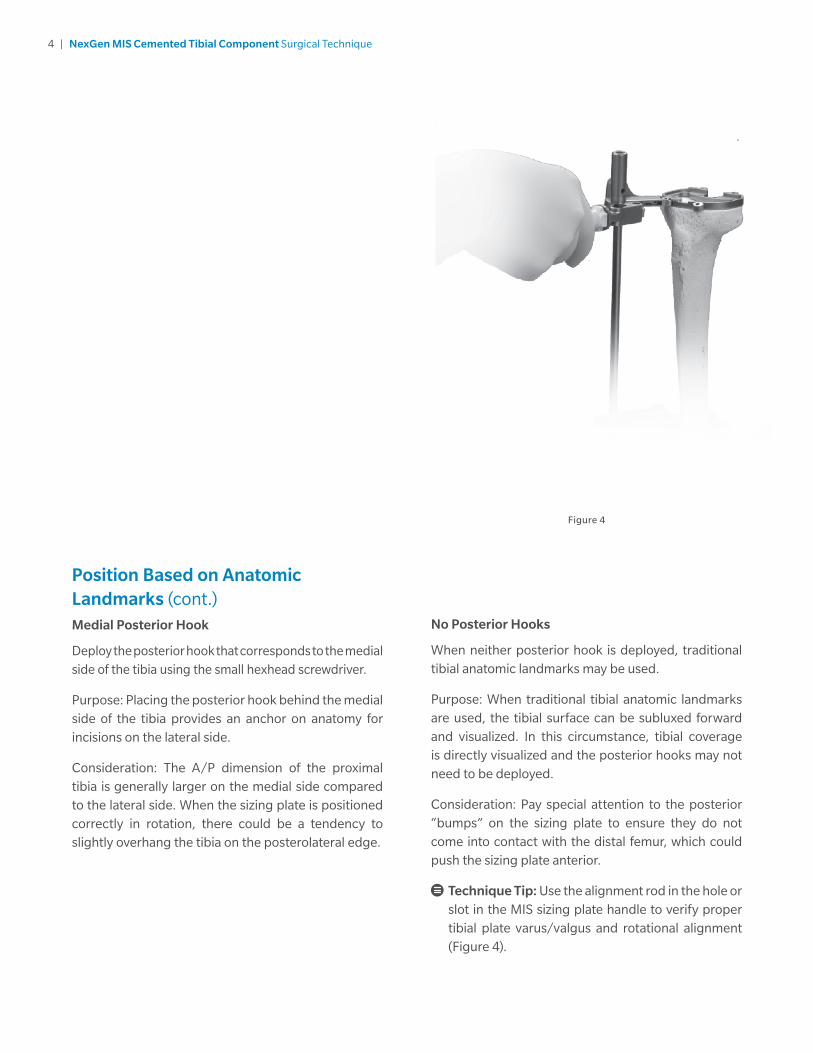
Position Based on Anatomic Landmarks (cont.)Medial Posterior Hook
Deploy the posterior hook that corresponds to the medial side of the tibia using the small hexhead screwdriver.
Purpose: Placing the posterior hook behind the medial side of the tibia provides an anchor on anatomy for incisions on the lateral side.
Consideration: The A/P dimension of the proximal tibia is generally larger on the medial side compared to the lateral side. When the sizing plate is positioned correctly in rotation, there could be a tendency to slightly overhang the tibia on the posterolateral edge.
No Posterior Hooks
When neither posterior hook is deployed, traditional tibial anatomic landmarks may be used.
Purpose: When traditional tibial anatomic landmarks are used, the tibial surface can be subluxed forward and visualized. In this circumstance, tibial coverage is directly visualized and the posterior hooks may not need to be deployed.
Consideration: Pay special attention to the posterior “bumps” on the sizing plate to ensure they do not come into contact with the distal femur, which could push the sizing plate anterior.
Technique Tip: Use the alignment rod in the hole or slot in the MIS sizing plate handle to verify proper tibial plate varus/valgus and rotational alignment (Figure 4).
Figure 4

5 | NexGen MIS Cemented Tibial Component Surgical Technique
Position Based on Anatomic Landmarks (cont.)Posterior Tab Deployed
Check that the chosen posterior hook(s) is completely deployed. Attach the MIS sizing plate handle to the selected MIS tibial sizing plate (Figure 5). The handle should be inserted on the medial side of the sizing plate to provide clearance for the patella.
Note: If lateral incision, then attach to lateral side of sizing plate.
Extend the lever on the handle and engage the tabs on the handle with the grooves on the sizing plate by positioning the lever lateral to the dovetail, and clamp the lever to secure.
Note: This instrument contains several moving parts. If trigger becomes hard to engage, apply instrument lubrication.
Locate the edge of the posterior tibial cortex with the hook and rotate the MIS sizing plate into position (Figure 6). Check that the sizing plate is not overlapping the posterior edges of the bone and that soft tissues have been cleared. Insert a pin or MIS screw into the anterior hole on the sizing plate (Figure 7). A second pin or MIS screw is inserted into the hole on the sizing plate. It is recommended to use one anterior pin hole and one hole on the opposite side of the sizing plate on the plate face to assure plate stability.
Caution: Do not impact or lever the MIS sizing plate handle; this instrument is designed for alignment purposes only.
Technique Tip: When using the anterior pin holes, pay special attention to the posterior aspect of the sizing plate to ensure lift-off does not occur from over tightening/seating.
Figure 5 Figure 7
Figure 6

6 | NexGen MIS Cemented Tibial Component Surgical Technique
Position Based on Anatomic Landmarks (cont.)Posterior Tab Deployed (cont.)
In extension, place the knee in valgus to view or palpate the lateral side of the tibia to check sizing plate fit laterally.
Be sure that the component is properly positioned rotationally. Tibial plate rotation and varus/valgus alignment can be checked by inserting the alignment rod through the hole or slot in the handle of the MIS sizing plate handle (Figure 8). There are two options available for use of the alignment rod (Figure 9):
Slot: Check varus/valgus and rotational alignment
Round Hole: Check slope of tibial cut (distal end of rod should point to second metatarsal)
Figure 10Figure 8
Figure 9
Position Based on Trial Range of MotionPrepare the patella. Then select the proper size MIS tibial sizing plate. Do not deploy either the posteromedial or posterolateral hooks on the sizing plate. Ensure that the plate chosen provides the desired tibial coverage. Insert the proper femoral provisional, patellar provisional, MIS tibial sizing plate, and bearing provisional. Select the color and/or alphanumeric designation of bearing provisional that is the same as the match chosen for the femoral provisional and MIS tibial sizing plate. Ensure soft tissue balance is appropriate. Flex and extend the knee with the provisionals in place. With proper soft tissue balancing complete, the tibial component tends to seat itself in the position where it best articulates with the femur.
After this process has occurred, mark the position of the component with methylene blue, electrocautery, or by placing a pin or MIS screw in the sizing plate anteriorly (Figure 10).

7 | NexGen MIS Cemented Tibial Component Surgical Technique
Figure 11
Position Based on Trial Range of Motion (cont.)
Remove the bearing provisional and pin the sizing plate in place with a MIS screw or shorthead holding pins (Figure 11). It is recommended to use one anterior pin hole and one hole on the opposite side of the sizing plate on the plate face to assure plate stability. Ensure that the MIS tibial sizing plate remains in the proper position when pinning.
Remove the MIS sizing plate handle from the MIS tibial sizing plate.
Technique Tip: When pinning the MIS sizing plate to the bone through the anterior angled pin holes, verify the posterior edge of the MIS sizing plate does not lift-off from the bone from over tightening/seating.
If the bearing provisional component has both the femoral sizes (alpha) and tibial sizes (numeric), then use these alphanumeric codes to match the three components. If the alphabetic and numeric sizes are not on the bearing provisional component, then use the color code to match the MIS tibial sizing plate. If there is no match between the femoral provisional and MIS tibial sizing plate, adjust the size of the MIS tibial sizing plate to obtain a match.

8 | NexGen MIS Cemented Tibial Component Surgical Technique
MIS Tibial Component Preparation without Stem Extension
Warning: It is strongly recommended to utilize a 45 mm or 75 mm drop down stem extension when using the MIS tibial component. Failure to use a drop down stem extension may lead to early loosening of the prosthesis.
Place the knee in appropriate flexion angle for broaching.
Assemble the proper size MIS cemented broach to the MIS tibial broach impactor as shown (Figure 12).
Figure 12 Figure 13 Figure 14
Seat the MIS tibial broach impactor assembly on the MIS tibial sizing plate in the detents (Figure 13).
During broaching, make sure that the broach handle remains flush against the sizing plate and in full contact with the sizing plate and that the broach handle does not toggle during impaction. Impact the MIS tibial broach Impactor assembly with care to prevent fracture of the tibia (Figure 14). Impact until the instrument bottoms out on the handle stop (Figure 14, inset).

9 | NexGen MIS Cemented Tibial Component Surgical Technique
MIS Tibial Component Preparation without Stem Extension (cont.)
Technique Tip: Keep the MIS tibial broach impactor as close to vertical as possible to facilitate proper broach position. The orientation of the broach handle is important to ensure proper and complete broaching resulting in full seating of the tibial implant on the bone.
Technique Tip: In order to facilitate positioning of the MIS cemented broach into the MIS sizing plate, the tibial medullary canal can be pre-drilled using the technique described in the upcoming section “MIS Tibial Component Preparation with Drop Down Stem Extension.”
The technique, however, should be modified to bore/drill only half the distance to the engraved line on the cemented drill. This depth will prepare for the length of the keel but will not prepare for the length of a drop down stem extension.
Figure 15
Correct Anterior Extraction Method
Remove the tibial broach impactor assembly and bone plug (Figure 15).
• Impact the under surface of the impaction head in the center of the anterior portion of the collar beneath the impaction head.
• Maintain a vertical impact direction in order to extract the broach straight out of the bone and avoid disruption of the broach preparation. Vertical extraction will also reduce stress on the instrument.
Warning: DO NOT extract with mallet blows on either the medial or lateral side of the under surface of the impaction head.
DO NOT attempt to extract the broach with a horizontal or angled blow on any side of the MIS broach impactor handle.
10 | NexGen MIS Cemented Tibial Component Surgical Technique
MIS Tibial Component Preparation without Stem Extension (cont.)
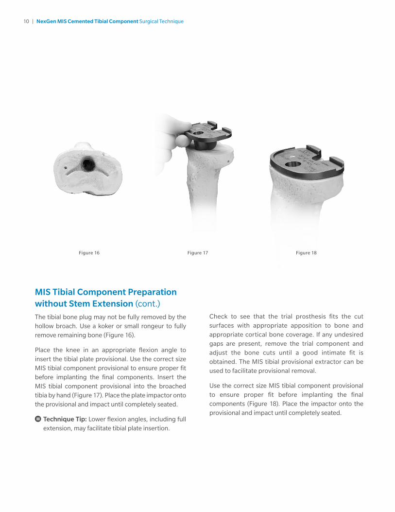
The tibial bone plug may not be fully removed by the hollow broach. Use a koker or small rongeur to fully remove remaining bone (Figure 16).
Place the knee in an appropriate flexion angle to insert the tibial plate provisional. Use the correct size MIS tibial component provisional to ensure proper fit before implanting the final components. Insert the MIS tibial component provisional into the broached tibia by hand (Figure 17). Place the plate impactor onto the provisional and impact until completely seated.
Technique Tip: Lower flexion angles, including full extension, may facilitate tibial plate insertion.
Figure 16 Figure 17 Figure 18
Check to see that the trial prosthesis fits the cut surfaces with appropriate apposition to bone and appropriate cortical bone coverage. If any undesired gaps are present, remove the trial component and adjust the bone cuts until a good intimate fit is obtained. The MIS tibial provisional extractor can be used to facilitate provisional removal.
Use the correct size MIS tibial component provisional to ensure proper fit before implanting the final components (Figure 18). Place the impactor onto the provisional and impact until completely seated.
11 | NexGen MIS Cemented Tibial Component Surgical Technique
Figure 19 Figure 20
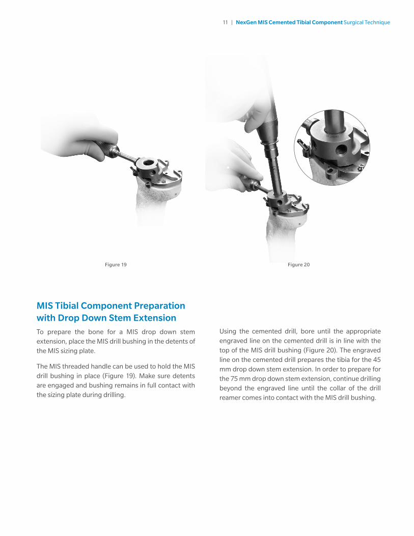
MIS Tibial Component Preparation with Drop Down Stem ExtensionTo prepare the bone for a MIS drop down stem extension, place the MIS drill bushing in the detents of the MIS sizing plate.
The MIS threaded handle can be used to hold the MIS drill bushing in place (Figure 19). Make sure detents are engaged and bushing remains in full contact with the sizing plate during drilling.
Using the cemented drill, bore until the appropriate engraved line on the cemented drill is in line with the top of the MIS drill bushing (Figure 20). The engraved line on the cemented drill prepares the tibia for the 45 mm drop down stem extension. In order to prepare for the 75 mm drop down stem extension, continue drilling beyond the engraved line until the collar of the drill reamer comes into contact with the MIS drill bushing.
12 | NexGen MIS Cemented Tibial Component Surgical Technique
MIS Tibial Component Preparation with Drop Down Stem Extension (cont.)
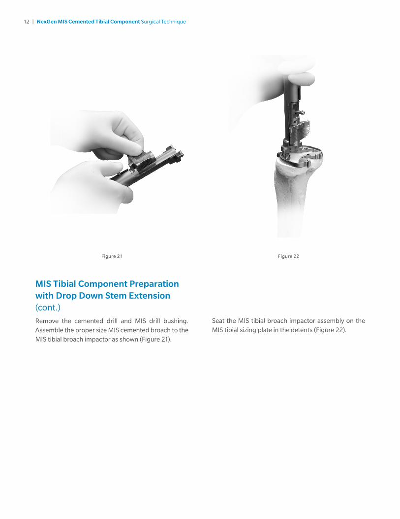
Remove the cemented drill and MIS drill bushing. Assemble the proper size MIS cemented broach to the MIS tibial broach impactor as shown (Figure 21).
Figure 21 Figure 22
Seat the MIS tibial broach impactor assembly on the MIS tibial sizing plate in the detents (Figure 22).

13 | NexGen MIS Cemented Tibial Component Surgical Technique
Figure 23 Figure 24
Correct Anterior Extraction Method
MIS Tibial Component Preparation with Drop Down Stem Extension (cont.)
During broaching, make sure that the broach handle remains flush against the sizing plate and in full contact with the sizing plate and that the broach handle does not toggle during broaching. Impact the MIS tibial broach impactor assembly with care to prevent fracture of the tibia (Figure 23). Impact until the instrument bottoms out on the handle stop (Figure 23, inset).
Remove the tibial broach impactor assembly and MIS tibial sizing plate (Figure 24).
• Impact the under surface of the impaction head in the center of the anterior portion of the collar beneath the impaction head.
• Maintain a vertical impact direction in order to extract the broach straight out of the bone and avoid disruption of the broach preparation. Vertical extraction will also reduce stress on the instrument.
Warning: DO NOT extract with mallet blows on either the medial or lateral side of the under surface of the impaction head.
DO NOT attempt to extract the broach with a horizontal or angled blow on any side of the MIS broach impactor handle.
14 | NexGen MIS Cemented Tibial Component Surgical Technique
MIS Tibial Component Preparation with Drop Down Stem Extension (cont.)
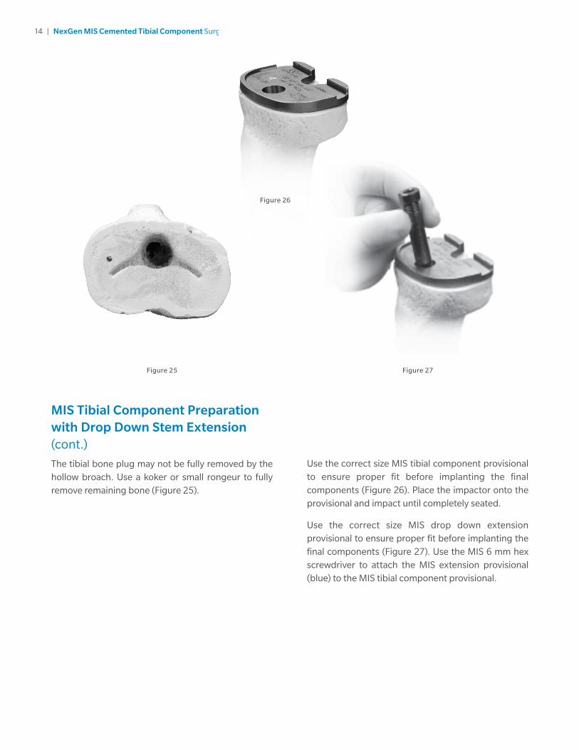
The tibial bone plug may not be fully removed by the hollow broach. Use a koker or small rongeur to fully remove remaining bone (Figure 25).
Figure 25 Figure 27
Figure 26
Use the correct size MIS tibial component provisional to ensure proper fit before implanting the final components (Figure 26). Place the impactor onto the provisional and impact until completely seated.
Use the correct size MIS drop down extension provisional to ensure proper fit before implanting the final components (Figure 27). Use the MIS 6 mm hex screwdriver to attach the MIS extension provisional (blue) to the MIS tibial component provisional.
15 | NexGen MIS Cemented Tibial Component Surgical Technique
MIS Tibial Component Preparation with Drop Down Stem Extension (cont.)
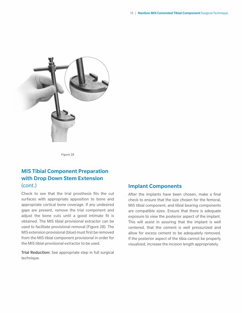
Check to see that the trial prosthesis fits the cut surfaces with appropriate apposition to bone and appropriate cortical bone coverage. If any undesired gaps are present, remove the trial component and adjust the bone cuts until a good intimate fit is obtained. The MIS tibial provisional extractor can be used to facilitate provisional removal (Figure 28). The MIS extension provisional (blue) must first be removed from the MIS tibial component provisional in order for the MIS tibial provisional extractor to be used.
Trial Reduction: See appropriate step in full surgical technique.
Figure 28
Implant ComponentsAfter the implants have been chosen, make a final check to ensure that the size chosen for the femoral, MIS tibial component, and tibial bearing components are compatible sizes. Ensure that there is adequate exposure to view the posterior aspect of the implant. This will assist in assuring that the implant is well centered, that the cement is well pressurized and allow for excess cement to be adequately removed. If the posterior aspect of the tibia cannot be properly visualized, increase the incision length appropriately.
16 | NexGen MIS Cemented Tibial Component Surgical Technique
Implant Components (cont.)
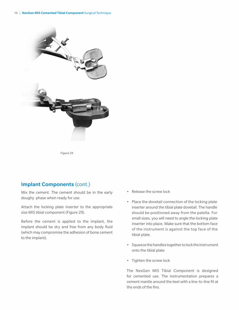
Mix the cement. The cement should be in the early doughy phase when ready for use.
Attach the locking plate inserter to the appropriate size MIS tibial component (Figure 29).
Before the cement is applied to the implant, the implant should be dry and free from any body fluid (which may compromise the adhesion of bone cement to the implant).
Figure 29
• Release the screw lock
• Place the dovetail connection of the locking plate inserter around the tibial plate dovetail. The handle should be positioned away from the patella. For small sizes, you will need to angle the locking plate inserter into place. Make sure that the bottom face of the instrument is against the top face of the tibial plate.
• Squeeze the handles together to lock the instrument onto the tibial plate
• Tighten the screw lock
The NexGen MIS Tibial Component is designed for cemented use. The instrumentation prepares a cement mantle around the keel with a line-to-line fit at the ends of the fins.

17 | NexGen MIS Cemented Tibial Component Surgical Technique
Implant Components (cont.)
Therefore, cement must be applied in the early doughy phase within the tibial medullary canal, as well as on the proximal tibial surface, under the tibial plate and around the keel.
Warning: The anterior and posterior surfaces of the NexGen MIS Tibial Component must be fully cemented in the doughy phase (i.e. before advanced cement polymerization occurs). Failure to fully cement and pressurize the anterior and posterior surfaces of the tibial component and/or cementing in the advanced stages of polymerization may lead to early loosening of the prosthesis.
Position the MIS tibial component onto the tibia (Figure 30). If a stem extension will NOT be used, impact until fully seated.
Remove any excess cement in the usual manner.
MIS Tibial Component with MIS Drop Down Extension
After inserting the MIS tibial component into the medullary canal with the poly plug in place, do NOT impact the component to fully seat onto the cut proximal surface of the bone. Final impaction should take place after the MIS drop down extension is inserted and fully tightened.
Use the MIS 6 mm hex screwdriver to remove the poly plug from the keel of the implant (Figure 31).
Figure 30 Figure 31
Cement Mantle
Line-to-Line Fit
Cross-section view

18 | NexGen MIS Cemented Tibial Component Surgical Technique
Implant Components (cont.)MIS Tibial Component with MIS Drop Down Extension (cont.)
Place the MIS drop down stem extension into the pre-drilled hole through the locking plate inserter (Figure 32). Use the MIS 6 mm hex screwdriver to completely hand tighten the threaded MIS drop down stem extension into the MIS tibial component (until head is below plate surface).
Use the torque wrench with MIS 6 mm hex driver to tighten the extension in place. Resist the torque with the locking plate inserter (Figure 33). The MIS drop down stem extension is fully tightened when the torque wrench needle reaches 95 in-lbs of force (Figure 34).
Figure 32
Figure 33
Figure 34
Remove the locking plate inserter and torque wrench. Impact until fully seated. Make sure that the MIS tibial component does not rock up posteriorly. Apply pressure evenly to the tibial component. Continue applying pressure until the tibial component cement has fully cured.
Remove any excess cement in the usual manner.
Implant the appropriately-sized femoral and patellar components. Insert a provisional bearing and place the knee in extension to maintain pressure on the cemented components until the cement is fully cured. Once the cement is completely cured, perform a trial reduction to identify the desired bearing thickness to best balance the soft tissues.

19 | NexGen MIS Cemented Tibial Component Surgical Technique
Implant Components (cont.)MIS Tibial Component with MIS Drop Down Extension (cont.)
Insert the bearing and lock into place with the articular surface inserter instrument (Figure 35).
If flex implants are being used and the bearing thickness is 17 mm or thicker, the following technique describes use of the MIS flex articular surface locking screw.
Figure 35
20 | NexGen MIS Cemented Tibial Component Surgical Technique
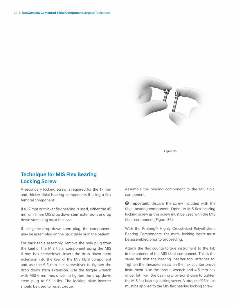
Technique for MIS Flex Bearing Locking Screw A secondary locking screw is required for the 17 mm and thicker tibial bearing components if using a flex femoral component.
If a 17 mm or thicker flex bearing is used, either the 45 mm or 75 mm MIS drop down stem extensions or drop down stem plug must be used.
If using the drop down stem plug, the components may be assembled on the back table or in the patient.
For back table assembly, remove the poly plug from the keel of the MIS tibial component using the MIS 6 mm hex screwdriver. Insert the drop down stem extension into the keel of the MIS tibial component and use the 6.5 mm hex screwdriver to tighten the drop down stem extension. Use the torque wrench with MIS 6 mm hex driver to tighten the drop down stem plug to 95 in-lbs. The locking plate inserter should be used to resist torque.
Figure 36
Assemble the bearing component to the MIS tibial component.
Important: Discard the screw included with the tibial bearing component. Open an MIS flex bearing locking screw as this screw must be used with the MIS tibial component (Figure 36).
With the Prolong® Highly Crosslinked Polyethylene Bearing Components, the metal locking insert must be assembled prior to proceeding.
Attach the flex countertorque instrument to the tab in the anterior of the MIS tibial component. This is the same tab that the bearing inserter tool attaches to. Tighten the threaded screw on the flex countertorque instrument. Use the torque wrench and 4.5 mm hex driver bit from the bearing provisional case to tighten the MIS flex bearing locking screw. A torque of 95 in-lbs must be applied to the MIS flex bearing locking screw.
21 | NexGen MIS Cemented Tibial Component Surgical Technique
Technique for MIS Flex Bearing Locking Screw (cont.)For in patient assembly
• Wait for the cement to completely cure before attaching the tibial bearing component.
Important: Discard the screw included with the tibial bearing. Open an MIS flex bearing locking screw as this screw will be used with the MIS tibial component.
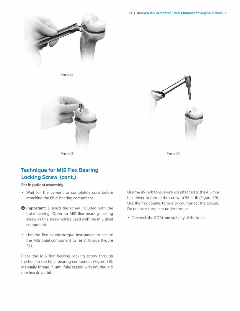
• Use the flex countertorque instrument to secure the MIS tibial component to resist torque (Figure 37).
Place the MIS flex bearing locking screw through the hole in the tibial bearing component (Figure 38). Manually thread in until fully seated with knurled 4.5 mm hex driver bit.
Figure 38 Figure 39
Figure 37
Use the 95 in-lb torque wrench attached to the 4.5 mm hex driver to torque the screw to 95 in-lb (Figure 39). Use the flex countertorque to counter-act the torque. Do not over-torque or under-torque.
• Recheck the ROM and stability of the knee.

97-5950-002-00 REV4-0916
Legal ManufacturerZimmer, Inc1800 West Center StreetWarsaw, IN 46581-0708USA
zimmerbiomet.com
All content herein is protected by copyright, trademarks and other intellectual property rights owned by or licensed to Zimmer Biomet or its affiliates unless otherwise indicated, and must not be redistributed, duplicated or disclosed, in whole or in part, without the express written consent of Zimmer Biomet.
This material is intended for health care professionals and Zimmer Biomet sales force. Distribution to any other recipient is prohibited.
For complete product information, including indications, contraindications, warnings, precautions, and potential adverse effects, see the package insert or zimmerbiomet.com.
©2016 Zimmer Biomet