Embed Size (px)
Citation preview
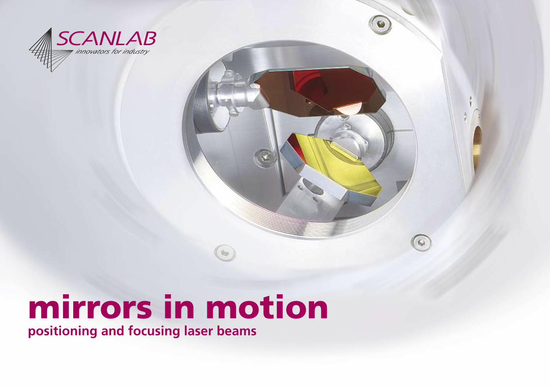
mirrors in motionpositioning and focusing laser beams
7, 10, 14, 20, 25, 30, 33, 50, 70 7, 10, 14, 20, 25, 30 7, 10 7, 10, 14 10 20, 25, 30 33, 50, 70 8 / 20, 16 / 40, 16 / 60, 16 / 80
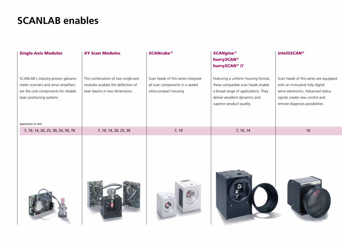
SCANLAB enables
XY Scan Modules
This combination of two single-axis
modules enables the deflection of
laser beams in two dimensions.
Single-Axis Modules
SCANLAB‘s industry-proven galvano-
meter scanners and servo amplifiers
are the core components for reliable
laser positioning systems.
SCANcube ®
Scan heads of this series integrate
all scan components in a sealed
ultra-compact housing.
SCANgine ®
hurrySCAN ®
hurrySCAN ® II
Featuring a uniform housing format,
these compatible scan heads enable
a broad range of applications. They
deliver excellent dynamics and
superior product quality.
intelliSCAN ®
Scan heads of this series are equipped
with an innovative fully digital
servo electronics. Advanced status
signals create new control and
remote-diagnosis possibilities.
Apertures in mm

7, 10, 14, 20, 25, 30, 33, 50, 70 7, 10, 14, 20, 25, 30 7, 10 7, 10, 14 10 20, 25, 30 33, 50, 70 8 / 20, 16 / 40, 16 / 60, 16 / 80
hurrySCAN ® 20 / 25 / 30
Maximum dynamic performance
and high laser power capability are
delivered by these compatible scan
heads. Their innovative design also
includes air and water cooling.
powerSCAN
Scan systems of this product line
enable new applications in the multi-
kW laser power range. Large working
fields and volumes are achievable
together with small spot diameters.
The modular design of
powerSCAN 50 and 70 allows easy
exchange of individual components.
varioSCAN
These focusing devices dynamically
vary the focal length and thereby
extend XY scan heads into versatile
3D beam deflection systems. The
varioSCANFLEX enables a continuous
variation of the image field size.
Optical Components
SCANLAB scan systems can be sup-
plied with a wide range of objec-
tives and mirrors. Customer-specific
designs are available.
positioning and focusing laser beams
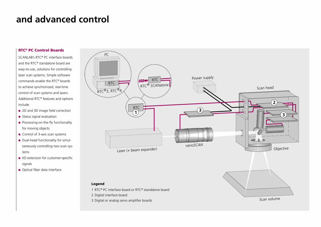
RTC® PC Control Boards
SCANLAB’s RTC® PC interface boards
and the RTC® standalone board are
easy-to-use, solutions for controlling
laser scan systems. Simple software
commands enable the RTC® boards
to achieve synchronized, real-time
control of scan systems and lasers.
Additional RTC® features and options
include:
2D and 3D image field correction
Status signal evaluation
Processing-on-the-fly functionality
for moving objects
Control of 3-axis scan systems
Dual-head functionality for simul-
taneously controlling two scan sys-
tems
I/O extension for customer-specific
signals
Optical fiber data interface
Legend
1 RTC® PC interface board or RTC® standalone board
2 Digital interface board
3 Digital or analog servo amplifier boards
and advanced control
for a wide range of applications.
06 / 2
005
Info
rmat
ion
is s
ubje
ct t
o ch
ange
with
out
notic
e.
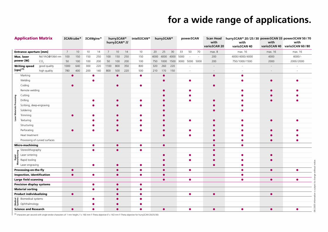
Application Matrix SCAN cube ® SCANgine ® hurrySCAN ®
hurrySCAN ® IIintelliSCAN ® hurrySCAN ® powerSCAN Scan Head
withvarioSCAN 20
hurrySCAN ® 20 / 25 / 30with
varioSCAN 40
powerSCAN 33with
varioSCAN 40
powerSCAN 50 / 70with
varioSCAN 60 / 80
Entrance aperture [mm] 7 10 10 14 7 10 14 10 20 25 30 33 50 70 max. 8 max. 16 max. 16 max. 16
Max. laser power [W]
Nd:YAG@1064 nm 100 150 150 250 100 150 250 150 4000 4000 4000 5000 - - 200 4000 / 4000 / 4000 4000 4000 / -
CO2 50 100 100 200 50 100 200 100 750 1000 1500 3000 5000 5000 200 750 / 1000 / 1500 2000 2000 / 2000
Writing speed [cps] (1)
good quality 1000 640 300 220 1100 800 350 800 320 260 220 - - - - -
high quality 780 400 200 140 800 500 220 500 210 170 150 - - - - -
Lase
r M
ater
ials
Pro
cess
ing
Marking
Welding
Coding
Remote welding
Cutting
Drilling
Scribing, deep-engraving
Soldering
Trimming
Texturing
Structuring
Perforating
Heat treatment
Processing of curved surfaces
Micro-machining
Rap
id
Man
ufa
ctu
rin
g Stereolithography
Laser sintering
Rapid tooling
Laser engraving
Processing-on-the-fly
Inspection, identification
Large field scanning
Precision display systems
Material sorting
Product individualizing
Med
ical
Sy
stem
s Biomedical systems
Ophthalmology
Science and Research
(1) characters per second with single-stroke characters of 1 mm height, f = 160 mm F-Theta objective (f = 163 mm F-Theta objective for hurrySCAN 20 / 25 / 30)
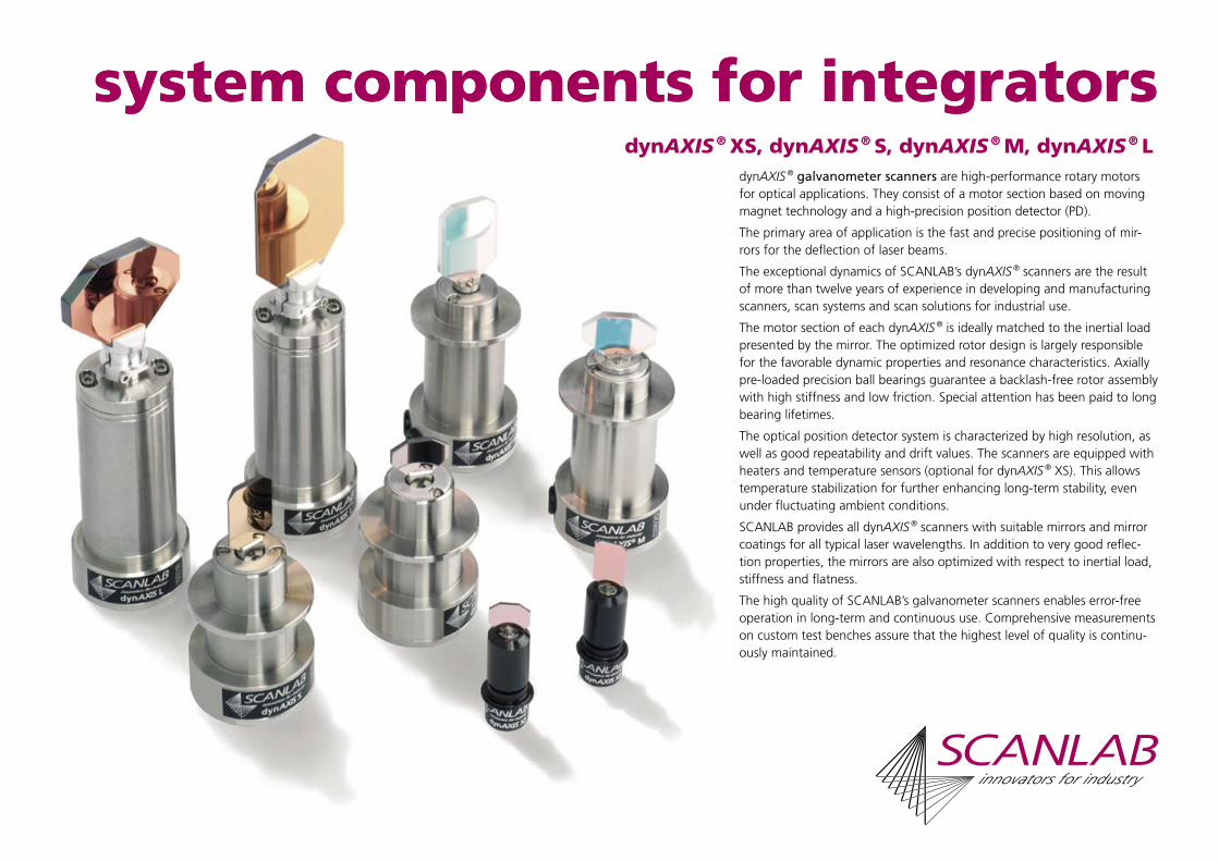
dynAXIS ® XS, dynAXIS ® S, dynAXIS ® M, dynAXIS ® L
system components for integratorssystem components for integratorsdynAXIS ® galvanometer scanners are high-performance rotary motors for optical applications. They consist of a motor section based on moving magnet technology and a high-precision position detector (PD).
The primary area of application is the fast and precise positioning of mir-rors for the deflection of laser beams.
The exceptional dynamics of SCANLAB’s dynAXIS ® scanners are the result of more than twelve years of experience in developing and manufacturing scanners, scan systems and scan solutions for industrial use.
The motor section of each dynAXIS ® is ideally matched to the inertial load presented by the mirror. The optimized rotor design is largely responsible for the favorable dynamic properties and resonance characteristics. Axially pre-loaded precision ball bearings guarantee a backlash-free rotor assembly with high stiffness and low friction. Special attention has been paid to long bearing lifetimes.
The optical position detector system is characterized by high resolution, as well as good repeatability and drift values. The scanners are equipped with heaters and temperature sensors (optional for dynAXIS ® XS). This allows temperature stabilization for further enhancing long-term stability, even under fluctuating ambient conditions.
SCANLAB provides all dynAXIS ® scanners with suitable mirrors and mirror coatings for all typical laser wavelengths. In addition to very good reflec-tion properties, the mirrors are also optimized with respect to inertial load, stiffness and flatness.
The high quality of SCANLAB’s galvanometer scanners enables error-free operation in long-term and continuous use. Comprehensive measurements on custom test benches assure that the highest level of quality is continu-ously maintained.
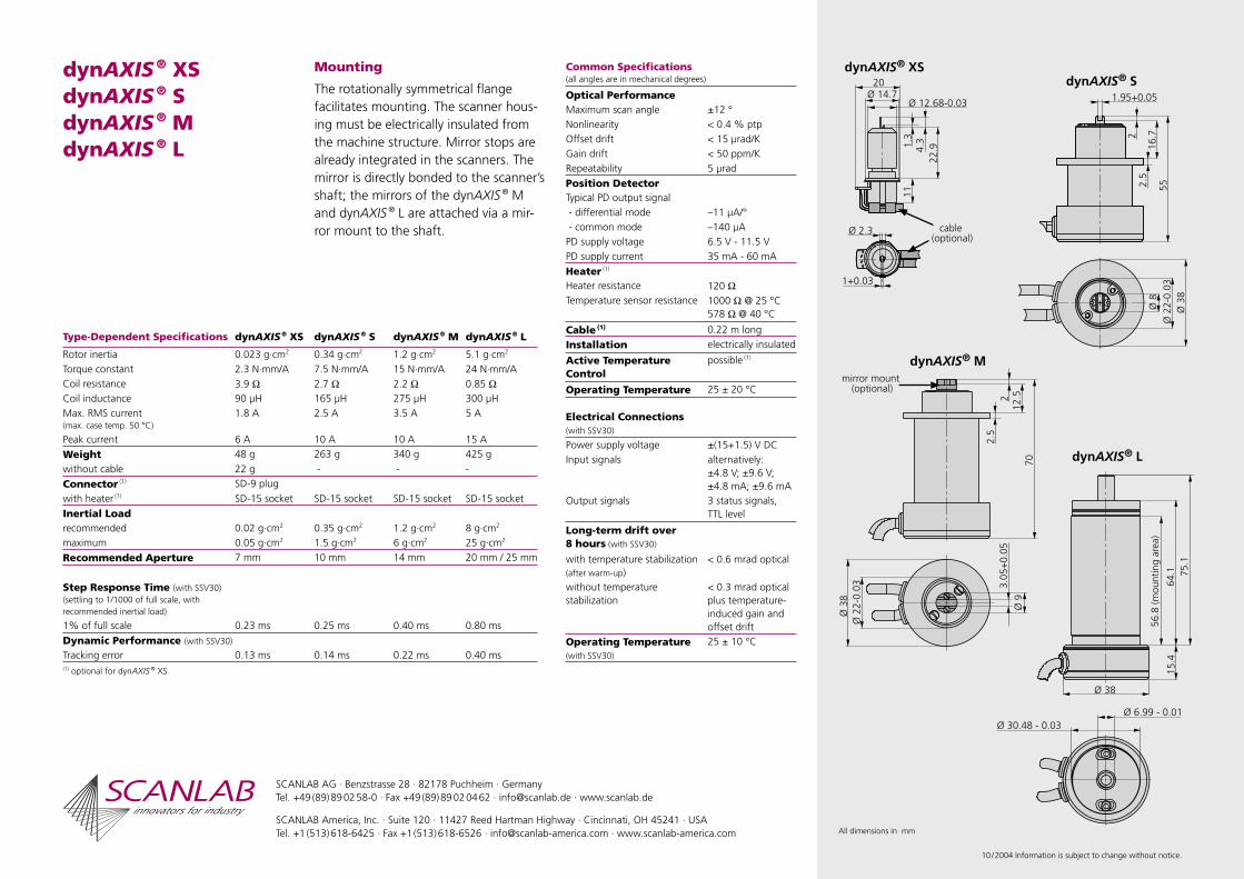
dynAXIS ® XS dynAXIS ® S dynAXIS ® MdynAXIS ® L
Mounting
The rotationally symmetrical flange facilitates mounting. The scanner hous-ing must be electrically insulated from the machine structure. Mirror stops are already integrated in the scanners. The mirror is directly bonded to the scanner’s shaft; the mirrors of the dynAXIS ® M and dynAXIS ® L are attached via a mir-ror mount to the shaft.
Common Specifications(all angles are in mechanical degrees)
Optical PerformanceMaximum scan angle ±12 °Nonlinearity < 0.4 % ptpOffset drift < 15 µrad/KGain drift < 50 ppm/KRepeatability 5 µrad
Position DetectorTypical PD output signal - differential mode –11 µA/° - common mode –140 µAPD supply voltage 6.5 V - 11.5 VPD supply current 35 mA - 60 mA
Heater (1)
Heater resistance 120 ΩTemperature sensor resistance 1000 Ω @ 25 °C
578 Ω @ 40 °C
Cable (1) 0.22 m long
Installation electrically insulated
Active Temperature Control
possible (1)
Operating Temperature 25 ± 20 °C
Electrical Connections (with SSV30)
Power supply voltage ±(15+1.5) V DCInput signals alternatively:
±4.8 V; ±9.6 V;±4.8 mA; ±9.6 mA
Output signals 3 status signals, TTL level
Long-term drift over 8 hours (with SSV30)
with temperature stabilization(after warm-up)
< 0.6 mrad optical
without temperature stabilization
< 0.3 mrad opticalplus temperature-induced gain and offset drift
Operating Temperature (with SSV30)
25 ± 10 °C
Type-Dependent Specifications dynAXIS ® XS dynAXIS ® S dynAXIS ® M dynAXIS ® L
Rotor inertia 0.023 g·cm2 0.34 g·cm2 1.2 g·cm2 5.1 g·cm2
Torque constant 2.3 N·mm/A 7.5 N·mm/A 15 N·mm/A 24 N·mm/ACoil resistance 3.9 Ω 2.7 Ω 2.2 Ω 0.85 ΩCoil inductance 90 µH 165 µH 275 µH 300 µHMax. RMS current(max. case temp. 50 °C)
1.8 A 2.5 A 3.5 A 5 A
Peak current 6 A 10 A 10 A 15 A
Weight 48 g 263 g 340 g 425 gwithout cable 22 g - - -
Connector (1) SD-9 plugwith heater (1) SD-15 socket SD-15 socket SD-15 socket SD-15 socket
Inertial Loadrecommended 0.02 g·cm2 0.35 g·cm2 1.2 g·cm2 8 g·cm2
maximum 0.05 g·cm2 1.5 g·cm2 6 g·cm2 25 g·cm2
Recommended Aperture 7 mm 10 mm 14 mm 20 mm / 25 mm
Step Response Time (with SSV30)(settling to 1/1000 of full scale, with recommended inertial load)
1% of full scale 0.23 ms 0.25 ms 0.40 ms 0.80 ms
Dynamic Performance (with SSV30)
Tracking error 0.13 ms 0.14 ms 0.22 ms 0.40 ms(1) optional for dynAXIS ® XS
SCANLAB AG · Benzstrasse 28 · 82178 Puchheim · GermanyTel. +49 (89) 89 02 58-0 · Fax +49 (89) 89 02 04 62 · [email protected] · www.scanlab.de
SCANLAB America, Inc. · Suite 120 · 11427 Reed Hartman Highway · Cincinnati, OH 45241 · USATel. +1 (513) 618-6425 · Fax +1 (513) 618-6526 · [email protected] · www.scanlab-america.com
10 / 2004 Information is subject to change without notice.
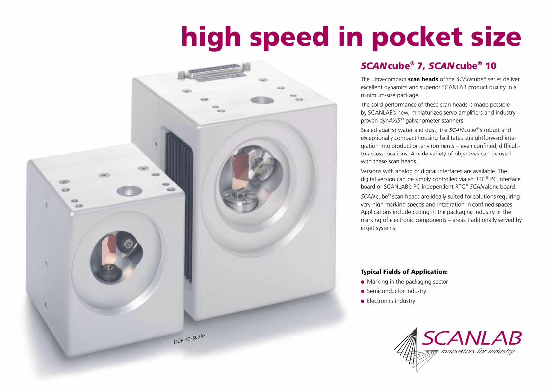
SCAN cube® 7, SCAN cube® 10
high speed in pocket sizeThe ultra-compact scan heads of the SCAN cube® series deliver excellent dynamics and superior SCANLAB product quality in a minimum-size package.
The solid performance of these scan heads is made possible by SCANLAB’s new, miniaturized servo amplifiers and industry-proven dynAXIS ® galvanometer scanners.
Sealed against water and dust, the SCAN cube®’s robust and exceptionally compact housing facilitates straightforward inte-gration into production environments – even confined, difficult-to-access locations. A wide variety of objectives can be used with these scan heads.
Versions with analog or digital interfaces are available. The digital version can be simply controlled via an RTC® PC interface board or SCANLAB’s PC-independent RTC® SCAN alone board.
SCAN cube® scan heads are ideally suited for solutions requiring very high marking speeds and integration in confined spaces. Applications include coding in the packaging industry or the marking of electronic components – areas traditionally served by inkjet systems.
Typical Fields of Application:
Marking in the packaging sector
Semiconductor industry
Electronics industry
true-to-scale

Common Specifications(all angles are in optical degrees)
Dynamic PerformanceRepeatability < 22 µrad
Offset drift 30 µrad/K
Gain drift 80 ppm/K
Long-term drift over 8 hours < 0.3 mradplus temperature-induced gain and offset drift
Optical PerformanceTypical scan angle ±0.35 rad
Gain error < 5 mrad
Zero offset < 5 mrad
Nonlinearity < 3.5 mrad
InterfaceAnalog version ±4.8 V
Digital version XY2-100 standard
Operating Temperature 25 °C ± 10 °C
SCANLAB AG · Benzstrasse 28 · 82178 Puchheim · GermanyTel. +49 (89) 89 02 58-0 · Fax +49 (89) 89 02 04 62 · [email protected] · www.scanlab.de
SCANLAB America, Inc. · Suite 120 · 11427 Reed Hartman Highway · Cincinnati, OH 45241 · USATel. +1 (513) 618-6425 · Fax +1 (513) 618-6526 · [email protected] · www.scanlab-america.com
06 / 2005 Information is subject to change without notice.
Legend
1 Beam in2 Screws (M5 thread) *3 Flange *4 Alignment pins (4h6) *5 Connector6 Beam out
* not included
SCAN cube® 7SCAN cube® 10
Optics
SCANLAB precisely optimizes and tunes all optical components to one another to ensure maximum focus quality and stable process parameters. Optical com-ponents offered by SCANLAB include exceptionally compact objectives, as well as objective adapters for standard objec-tives. Optics for various wavelengths, power densities, focal lengths and im-age fields are available.
Control
SCAN cube® scan heads are equipped with either an analog or a digital standard interface accessible via a 25-pin D-SUB connector.They are easily controlled via SCANLAB’s RTC® PC interface board or the PC-inde-pendent RTC® SCAN alone board from SCANLAB.
Quality
The high quality of SCANLAB’s scan solutions is the result of more than four-teen years of experience in the develop-ment and manufacture of galvanometer scanners and scan systems. In addition, every scan system must first pass the SCAN check burn-in test before it is released for shipment to the customer.
Type-Dependent Specifications (all angles are in optical degrees)
SCAN cube ® 7 SCAN cube ® 10
Aperture 7 mm 10 mm
Beam displacement 9.98 mm 13.09 mm
Dynamic PerformanceTracking error 0.14 ms 0.18 ms
Optical PerformanceSkew < 6 mrad < 1.5 mrad
Step Response Time(settling to 1/1000 of full scale)
1% of full scale 0.25 ms 0.40 ms
10% of full scale 0.90 ms 1.2 ms
Typical Speeds (1)
Marking speed 2.5 m/s 2.0 m/s
Positioning speed 12.0 m/s 7.0 m/s
Writing speed (2)
good writing quality 900 cps 640 cps
high writing quality 600 cps 400 cps
Power Requirements ±15 V DC,max. 2 A each
±15 V DC,max. 3 A each
Weight (without objective) 650 g 1.9 kg(1) with F-Theta objective, f = 160 mm (2) single-stroke characters of 1 mm height

universal and compatiblehurrySCAN ® II, hurrySCAN ®, SCAN gine ®
These compact scan heads from SCANLAB provide optimal solutions for nearly all challenges found in industrial laser materials processing. The mechanically and electrically inter-compatible scan heads have apertures ranging from 10 to 14 mm and various levels of dynamics. High long-term stability and low drift values are ensured via integrated temperature stabilization.
A uniform housing concept as well as tight manufacturing and assembly tolerances bring high flexibility and certainty to the design and operation of laser materials processing systems. This also enables speedy adaptation to individual customer require-ments.
The hurrySCAN ® II scan heads set new high-end performance standards with their optimized combination of dynAXIS ® galvanometer scanners, mirror designs and high-performance electronics.
The high quality of SCANLAB’s scan heads is the result of more than 15 years of experience in the development and manufac-ture of galvanometer scanners and scan systems. In addition, each scan head must first pass the SCAN check burn-in test before it is released for shipment to the customer.
Typical Fields of Application:
Industry: marking, laser materials processing (e.g. deep engraving, drilling, ablation, cutting, welding), electronics production (e.g. trimming, drilling, structuring), microstructuring, rapid manufacturing, stereolithography
Medicine
Science and research

Type-Dependent Specifications(all angles are in optical degrees) hurrySCAN ® II hurrySCAN ® SCAN gine ®
Aperture 10 mm 14 mm 10 mm 14 mm 10 mm 14 mm
Beam Displacement (dimension a) 12.56 mm 16.42 mm 12.56 mm 15.79 mm 12.56 mm 15.79 mm
Step Response Time(settling to 1/1000 of full scale)
1 % of full scale 0.25 ms 0.40 ms 0.35 ms 0.80 ms 0.80 ms 1.10 ms10 % of full scale - 1.60 ms 0.90 ms 2.20 ms 2.00 ms 2.60 ms
Typical Speeds (1)
Marking speed 2.5 m/s 1.5 m/s 2.0 m/s 1.0 m/s 1.0 m/s 0.7 m/sPositioning speed 10.0 m/s 7.0 m/s 7.0 m/s 7.0 m/s 7.0 m/s 5.0 m/sWriting speed (2)
good quality 800 cps 500 cps 640 cps 350 cps 300 cps 220 cpshigh quality 500 cps 340 cps 400 cps 220 cps 200 cps 140 cps
Dynamic PerformanceTracking error 0.14 ms 0.24 ms 0.18 ms 0.42 ms 0.42 ms 0.55 msLong-term drift over 8 hours(after warm-up)
< 0.6 mrad <0.6 mrad < 0.6 mrad < 0.6 mrad < 0.6 mrad < 0.6 mrad
Nonlinearity < 3.5 mrad <3.5 mrad < 3.5 mrad < 2.1 mrad < 2.1 mrad < 2.1 mrad(1) with F-Theta objective, f = 160 mm (2) single-stroke characters of 1 mm height
hurrySCAN ® II hurrySCAN ® SCAN gine ®
Optics
Galvanometer mirrors and objectives with optimized mounts are available for all typical laser types and image fields.
Control
All scan heads of these series are equipped with either analog or digital standard interfaces and are easily con-trolled via SCANLAB’s RTC® PC interface boards. All scan heads are optionally available with an optical fiber data in-terface.
Options
A varioSCAN can extend all SCANLAB compact scan heads into three-axis scan systems.
Scan heads with 14 mm apertures can be equipped with an additional reference sensor system for automatic self-calibration in scan systems requir-ing extremely high long-term posi-tioning stability.
All of SCANLAB’s compact scan heads are also available without a housing as scan modules.
Common Specifications(all angles are in optical degrees)
Dynamic PerformanceRepeatability < 22 µrad
Optical PerformanceTypical scan angle ±0.35 radGain error < 5 mradZero offset < 5 mradSkew < 1.5 mrad
Power Requirements ±(15+1.5) V DC,max. 3 A each
Input SignalsAnalog version alternatively:
±4.8 V; ±9.6 V;±4.8 mA; ±9.6 mA
Digital version XY2-100 standard or optical data transfer
Output Signals 3 status signals per axis
Analog version TTL levelDigital version XY2-100 standard or
optical data transfer
Weight (without objective) approx. 3 kg
Operating Temperature 25 °C ± 10 °C
Legend
1 Beam in2 Screws (M6 thread) *3 Flange *4 Alignment pins (6h6) *5 Mounting bracket6 Connectors7 Objective8 Beam out
* not included
02 / 2005 Information is subject to change without notice.
SCANLAB AG · Benzstrasse 28 · 82178 Puchheim · GermanyTel. +49 (89) 89 02 58-0 · Fax +49 (89) 89 02 04 62 · [email protected] · www.scanlab.de
SCANLAB America, Inc. · Suite 120 · 11427 Reed Hartman Highway · Cincinnati, OH 45241 · USATel. +1 (513) 618-6425 · Fax +1 (513) 618-6526 · [email protected] · www.scanlab-america.com
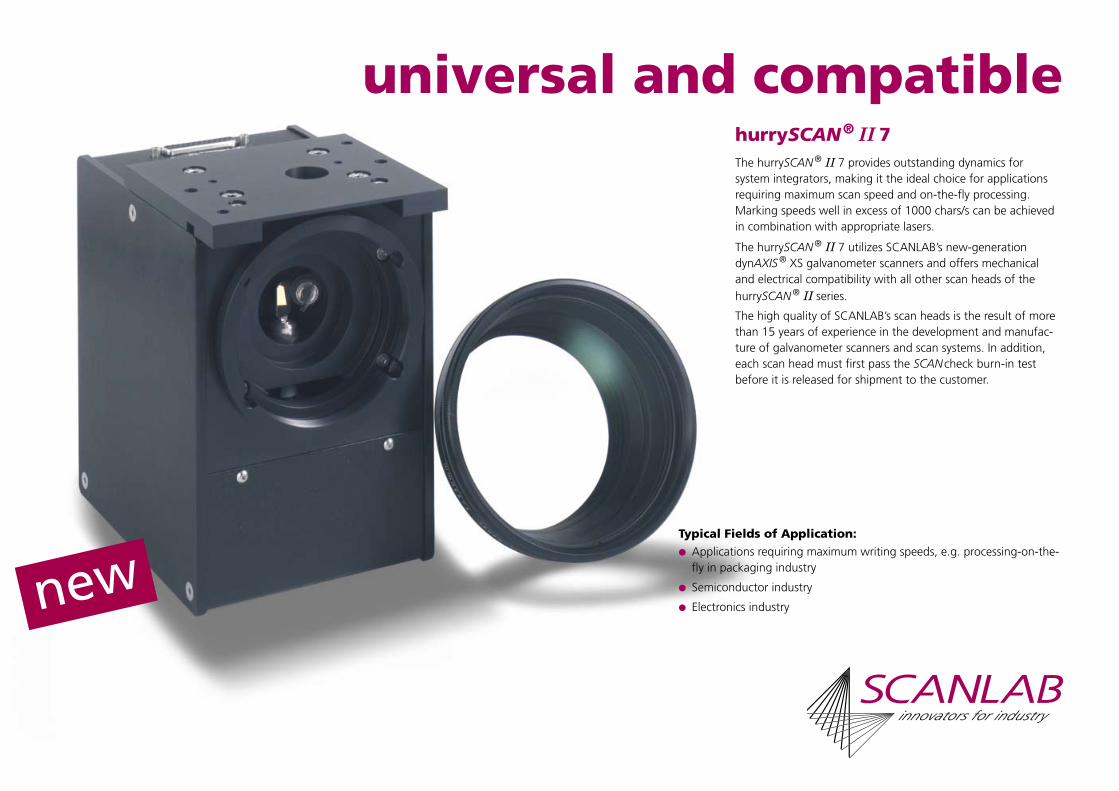
universal and compatiblehurrySCAN ® II 7The hurrySCAN ® II 7 provides outstanding dynamics for system integrators, making it the ideal choice for applications requiring maximum scan speed and on-the-fly processing. Marking speeds well in excess of 1000 chars/s can be achieved in combination with appropriate lasers.
The hurrySCAN ® II 7 utilizes SCANLAB’s new-generation dynAXIS ® XS galvanometer scanners and offers mechanical and electrical compatibility with all other scan heads of the hurrySCAN ® II series.
The high quality of SCANLAB’s scan heads is the result of more than 15 years of experience in the development and manufac-ture of galvanometer scanners and scan systems. In addition, each scan head must first pass the SCAN check burn-in test before it is released for shipment to the customer.
Typical Fields of Application: Applications requiring maximum writing speeds, e.g. processing-on-the-
fly in packaging industry
Semiconductor industry
Electronics industry

hurrySCAN ® II 7
Optics
SCANLAB precisely optimizes and tunes all optical components to one another to ensure maximum focus quality and stable process parameters. Optics for various wavelengths, power densities, focal lengths and image fields areavailable.
Control
The hurrySCAN ® II 7 is equipped with either an analog or a digital standard interface and is easily controlled via a SCANLAB RTC® interface board. The RTC®’s processor performs vital steps such as micro-vectorization, coordinate transformations and image field correction. The hurrySCAN ® II 7 is optionally available with an optical fiber data interface.
Options
The varioSCAN 20 extends the hurrySCAN ® II 7 into a three-axis scan system.
The hurrySCAN ® II 7 is also available without a housing as a scan module.
Specifications (all angles are in optical degrees)
Aperture 7 mm
Step Response Time(settling to 1/1000 of full scale)
1% of full scale 0.30 ms
10% of full scale 1.00 ms
Typical Speeds (1)
Marking speed 3.5 m/s
Positioning speed 15.0 m/s
Writing speed (2)
good quality 1100 cps
high quality 800 cps
Dynamic PerformanceTracking error 0.11 ms
Repeatability < 22 µrad
Long-term drift over 8 hours(at constant ambient conditions)
< 0.3 mrad
Offset drift < 30 µrad/K
Gain drift < 100 ppm/K
Optical PerformanceTypical scan angle ±0.35 rad
Gain error < 5 mrad
Zero offset < 5 mrad
Skew < 1.5 mrad
Nonlinearity < 3.5 mrad
Power Requirements ±(15+1.5) V DC,max. 3 A each
Input SignalsAnalog version alternatively:
±4.8 V; ±9.6 V;±4.8 mA; ±9.6 mA
Digital version XY2-100 standard or optical data transfer
Output Signals 3 status signals per axis
Analog version TTL level
Digital version XY2-100 standard or optical data transfer
Weight (without objective) 3 kg
Operating Temperature 25 °C ± 10 °C(1) with F-Theta objective, f =160 mm(2) single-stroke characters of 1 mm height
Legend
1 Beam in2 Screws (M6 thread) *3 Flange *4 Alignment pins (6h6) *5 Mounting bracket6 Connectors7 Objective8 Beam out
* not included
06 / 2005 Information is subject to change without notice.
SCANLAB AG · Benzstrasse 28 · 82178 Puchheim · GermanyTel. +49 (89) 89 02 58-0 · Fax +49 (89) 89 02 04 62 · [email protected] · www.scanlab.de
SCANLAB America, Inc. · Suite 120 · 11427 Reed Hartman Highway · Cincinnati, OH 45241 · USATel. +1 (513) 618-6425 · Fax +1 (513) 618-6526 · [email protected] · www.scanlab-america.com
intelliSCAN ® 10
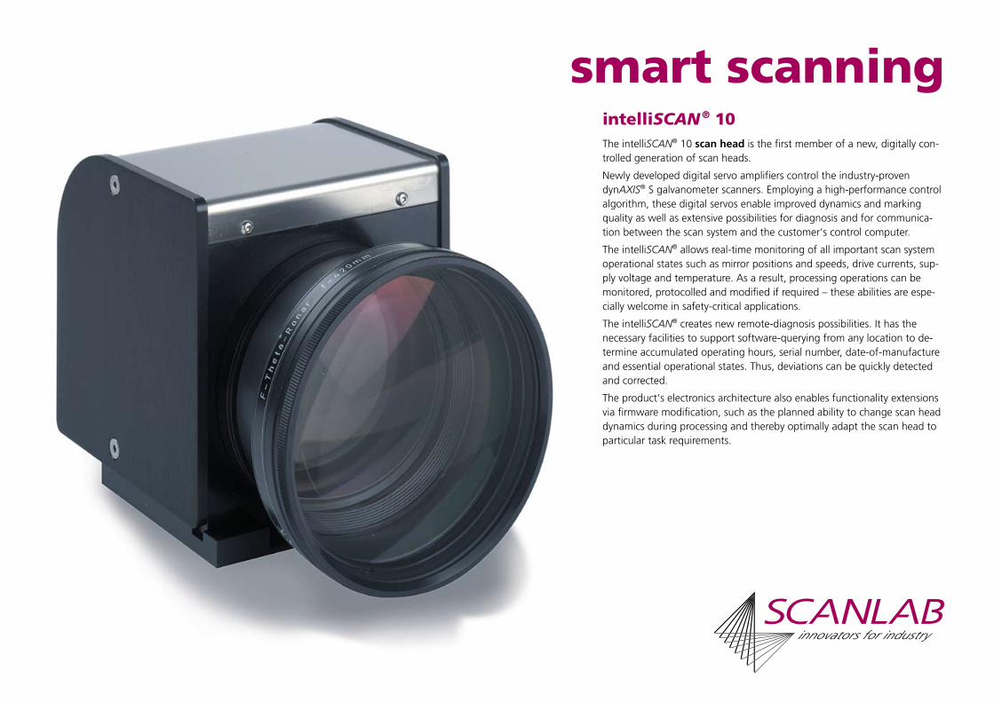
smart scanningThe intelliSCAN® 10 scan head is the first member of a new, digitally con-trolled generation of scan heads.
Newly developed digital servo amplifiers control the industry-proven dynAXIS® S galvanometer scanners. Employing a high-performance control algorithm, these digital servos enable improved dynamics and marking quality as well as extensive possibilities for diagnosis and for communica-tion between the scan system and the customer‘s control computer.
The intelliSCAN® allows real-time monitoring of all important scan system operational states such as mirror positions and speeds, drive currents, sup-ply voltage and temperature. As a result, processing operations can be monitored, protocolled and modified if required – these abilities are espe-cially welcome in safety-critical applications.
The intelliSCAN® creates new remote-diagnosis possibilities. It has the necessary facilities to support software-querying from any location to de-termine accumulated operating hours, serial number, date-of-manufacture and essential operational states. Thus, deviations can be quickly detected and corrected.
The product‘s electronics architecture also enables functionality extensions via firmware modification, such as the planned ability to change scan head dynamics during processing and thereby optimally adapt the scan head to particular task requirements.

intelliSCAN ® 10
Optics
Galvanometer mirrors and objectives with optimized mounts are available for all typical laser types and image fields.
Control
The intelliSCAN® is equipped with a digital interface and is easily controlled via SCANLAB’s RTC®4 PC interface board. Scan head diagnosis and all es-sential configuration parameters are controlled via software commands.
The intelliSCAN® is optionally available with an optical fiber data interface.
Quality
The high quality of SCANLAB’s scan so-lutions is the result of more than twelve years of experience in the development and manufacture of galvanometer scanners and scan systems. In addi-tion, every scan system must first pass the SCAN check burn-in test before it is released for shipment to the customer.
Preliminary Specifications(all angles are in optical degrees)
Aperture 10 mm
Beam Displacement 12.56 mm
Step Response Time(settling to 1/1000 of full scale)
1% of full scale 0.35 ms
10% of full scale 0.90 ms
Typical Speeds (1)
Marking speed 2.0 m/s
Positioning speed 7.0 m/s
Writing speed (2)
good quality 640 cps
high quality 400 cps
Dynamic PerformanceTracking error 0.18 ms
Repeatability < 22 µrad
Long-term drift over 8 hours(after warm-up)
< 0.6 mrad
Optical PerformanceTypical scan angle ±0.35 rad
Gain error < 5 mrad
Zero offset < 5 mrad
Skew < 1.5 mrad
Nonlinearity < 3.5 mrad
Power Requirements ±15 V DC,max. 3 A eachor30 V DC, max. 3 A
Interface XY2-100 Enhanced or optical data transfer
Weight (without objective) 2.7 kg
Operating Temperature 25 °C ± 10 °C(1) with F-Theta objective, f =160 mm(2) single-stroke characters of 1 mm height
SCANLAB AG · Benzstrasse 28 · 82178 Puchheim · GermanyTel. +49 (89) 89 02 58-0 · Fax +49 (89) 89 02 04 62 · [email protected] · www.scanlab.de
SCANLAB America, Inc. · Suite 120 · 11427 Reed Hartman Highway · Cincinnati, OH 45241 · USATel. +1 (513) 618-6425 · Fax +1 (513) 618-6526 · [email protected] · www.scanlab-america.com
08 / 2003 Information is subject to change without notice.
Legend
1 Beam in2 Screws (M6 thread) *3 Flange *4 Alignment pins (6h6) *5 Mounting bracket6 Connectors7 Objective8 Beam out
* not included
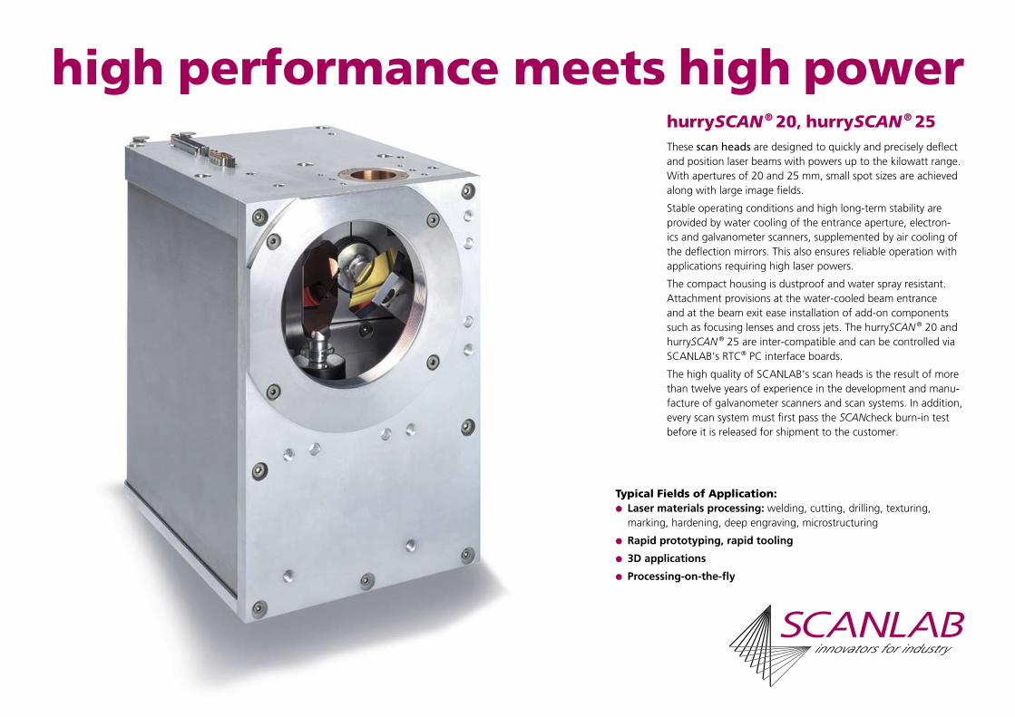
high performance meets high power hurrySCAN ® 20, hurrySCAN ® 25These scan heads are designed to quickly and precisely deflect and position laser beams with powers up to the kilowatt range. With apertures of 20 and 25 mm, small spot sizes are achieved along with large image fields.
Stable operating conditions and high long-term stability are provided by water cooling of the entrance aperture, electron-ics and galvanometer scanners, supplemented by air cooling of the deflection mirrors. This also ensures reliable operation with applications requiring high laser powers.
The compact housing is dustproof and water spray resistant. Attachment provisions at the water-cooled beam entrance and at the beam exit ease installation of add-on components such as focusing lenses and cross jets. The hurrySCAN ® 20 and hurrySCAN ® 25 are inter-compatible and can be controlled via SCANLAB’s RTC® PC interface boards.
The high quality of SCANLAB’s scan heads is the result of more than twelve years of experience in the development and manu-facture of galvanometer scanners and scan systems. In addition, every scan system must first pass the SCANcheck burn-in test before it is released for shipment to the customer.
Typical Fields of Application: Laser materials processing: welding, cutting, drilling, texturing,
marking, hardening, deep engraving, microstructuring
Rapid prototyping, rapid tooling
3D applications
Processing-on-the-fly

Legend
1 Beam in2 Mounting screws (M6 threads) *3 Flange *4 Alignment pins (6h6) *5 Objective6 Beam outE Electrical connectorsA Connector for cooling airW Connector for cooling water
* not included
Type-Dependent Specifications (all angles are in optical degrees)
hurrySCAN ® 20 hurrySCAN ® 25
Aperture 20 mm 25 mm
Beam displacement (dimension a) 25.25 mm 29.88 mm
Dimension b 67.25 mm 72.00 mm
Optical PerformanceTypical scan angle of scanner 1 ±0.35 rad ±0.26 radTypical scan angle of scanner 2 ±0.35 rad ±0.40 radTypical field size – ellipse (1), (2) - 80 mm x 130 mm
Typical field size – square (1), (2) 90 mm x 90 mm 75 mm x 75 mm
Dynamic PerformanceTracking error 0.40 ms 0.50 ms
Step Response Time(settling to 1/1000 of full scale)
1% of full scale 0.8 ms 0.9 ms
10% of full scale 2.5 ms 3.2 ms
Typical Speeds (1)
Marking speed 1.0 m/s 0.8 m/s
Positioning speed 6.0 m/s 5.0 m/s
Writing speed (3)
good writing quality 320 cps 260 cps
high writing quality 210 cps 170 cps(1) with F-Theta objective, f = 163 mm (2) limited by vignetting at objective (3) single-stroke characters of 1 mm height
hurrySCAN ® 20hurrySCAN ® 25
Optics
Galvanometer mirrors and objectives with optimized mounts are available for all typical laser types and working fields.
To optimally utilize standard objectives, the hurrySCAN ® 25’s two scan axes have differing maximum scan angles. This results in an elliptical image field with the larger semi-axis perpendicular to the entrance beam axis.
Attachment Provisions
The housing’s beam entrance side pro-vides a tight-tolerance beam entrance hole with a fine-pitched thread for at-taching focusing lenses and apertures. Additional threaded and non-threaded holes facilitate mounting of the scan head and installation of fiber optic out-puts.
On the beam exit side, threaded holes are available for attaching add-on com-ponents such as cross jets, illumination, distance sensors or thermal shields.
Common Specifications(all angles are in optical degrees)
Dynamic PerformanceRepeatability < 22 µrad
Offset drift < 25 µrad/K
Gain drift < 80 ppm/K
Long-term drift over 8 hours(constant ambient conditions)
< 0.3 mrad
Optical PerformanceGain error < 5 mrad
Zero offset < 5 mrad
Skew < 1.5 mrad
Nonlinearity < 2.1 mrad
Power Requirements ±(15+1.5) V DC,max. 6 A each
Input SignalsAnalog version alternatively:
±4.8 V; ±9.6 V;±4.8 mA; ±9.6 mA
Digital version XY2-100 standard or optical data transfer
Output Signals 3 status signals per axis
Analog version TTL level
Digital version XY2-100 standard or optical data transfer
Weight (without objective) approx. 5.8 kg
Operating Temperature 25 °C ± 10 °C
Typical Air Requirements
clean, filtered air20 l/min at ∆p < 2 bar
Typical Water Requirements
5 l/min at∆p < 0.1 bar, p < 4 bar
Options
A varioSCAN can extend the hurrySCAN ® scan heads into 3D scan systems.
These scan heads can be equipped with an additional reference sensor system for automatic self-calibration to obtain extremely high long-term stability.
SCANLAB AG · Benzstrasse 28 · 82178 Puchheim · GermanyTel. +49 (89) 89 02 58-0 · Fax +49 (89) 89 02 04 62 · [email protected] · www.scanlab.de
SCANLAB America, Inc. · Suite 120 · 11427 Reed Hartman Highway · Cincinnati, OH 45241 · USATel. +1 (513) 618-6425 · Fax +1 (513) 618-6526 · [email protected] · www.scanlab-america.com
08 / 2003 Information is subject to change without notice.
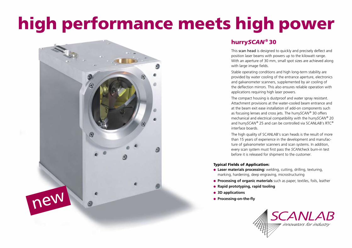
high performance meets high power hurrySCAN ® 30This scan head is designed to quickly and precisely deflect and position laser beams with powers up to the kilowatt range. With an aperture of 30 mm, small spot sizes are achieved along with large image fields.
Stable operating conditions and high long-term stability are provided by water cooling of the entrance aperture, electronics and galvanometer scanners, supplemented by air cooling of the deflection mirrors. This also ensures reliable operation with applications requiring high laser powers.
The compact housing is dustproof and water spray resistant. Attachment provisions at the water-cooled beam entrance and at the beam exit ease installation of add-on components such as focusing lenses and cross jets. The hurrySCAN ® 30 offers mechanical and electrical compatibility with the hurrySCAN ® 20 and hurrySCAN ® 25 and can be controlled via SCANLAB’s RTC® interface boards.
The high quality of SCANLAB’s scan heads is the result of more than 15 years of experience in the development and manufac-ture of galvanometer scanners and scan systems. In addition, every scan system must first pass the SCANcheck burn-in test before it is released for shipment to the customer.
Typical Fields of Application: Laser materials processing: welding, cutting, drilling, texturing,
marking, hardening, deep engraving, microstructuring
Processing of organic materials such as paper, textiles, foils, leather
Rapid prototyping, rapid tooling
3D applications
Processing-on-the-fly
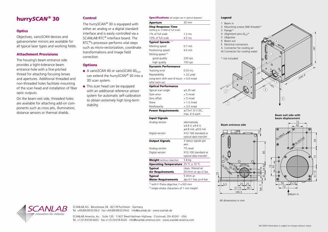
Legend
1 Beam in2 Mounting screws (M6 threads) *3 Flange *4 Alignment pins (6h6) *5 Objective6 Beam outE Electrical connectorsA Connector for cooling airW Connector for cooling water
* not included
hurrySCAN ® 30
Optics
Objectives, varioSCAN devices and galvanometer mirrors are available for all typical laser types and working fields.
Attachment Provisions
The housing’s beam entrance side provides a tight-tolerance beam entrance hole with a fine-pitched thread for attaching focusing lenses and apertures. Additional threaded and non-threaded holes facilitate mounting of the scan head and installation of fiber optic outputs.
On the beam exit side, threaded holes are available for attaching add-on com-ponents such as cross jets, illumination, distance sensors or thermal shields.
Control
The hurrySCAN ® 30 is equipped with either an analog or a digital standard interface and is easily controlled via a SCANLAB RTC® interface board. The RTC®’s processor performs vital steps such as micro-vectorization, coordinate transformations and image field correction.
Options
A varioSCAN 40 or varioSCAN 40FLEX can extend the hurrySCAN ® 30 into a 3D scan system.
This scan head can be equipped with an additional reference sensor system for automatic self-calibration to obtain extremely high long-term stability.
SCANLAB AG · Benzstrasse 28 · 82178 Puchheim · GermanyTel. +49 (89) 89 02 58-0 · Fax +49 (89) 89 02 04 62 · [email protected] · www.scanlab.de
SCANLAB America, Inc. · Suite 120 · 11427 Reed Hartman Highway · Cincinnati, OH 45241 · USATel. +1 (513) 618-6425 · Fax +1 (513) 618-6526 · [email protected] · www.scanlab-america.com
06 / 2005 Information is subject to change without notice.
Specifications (all angles are in optical degrees)
Aperture 30 mm
Step Response Time(settling to 1/1000 of full scale)
1% of full scale 1.2 ms
10% of full scale 4.5 ms
Typical Speeds (1)
Marking speed 0.7 m/s
Positioning speed 4.5 m/s
Writing speed (2)
good quality 220 cps
high quality 150 cps
Dynamic PerformanceTracking error 0.55 ms
Repeatability < 22 µrad
Long-term drift over 8 hours(after warm-up)
< 0.6 mrad
Optical PerformanceTypical scan angle ±0.35 rad
Gain error < 5 mrad
Zero offset < 5 mrad
Skew < 1.5 mrad
Nonlinearity < 3.5 mrad
Power Requirements ±(15+1.5) V DC,max. 6 A each
Input SignalsAnalog version alternatively:
±4.8 V; ±9.6 V;±4.8 mA; ±9.6 mA
Digital version XY2-100 standard or optical data transfer
Output Signals 3 status signals per axis
Analog version TTL level
Digital version XY2-100 standard or optical data transfer
Weight (without objective) 5.8 kg
Operating Temperature 25 °C ± 10 °C
Typical Air Requirements
clean, filtered air20 l/min at ∆p < 2 bar
Typical Water Requirements
5 l/min at∆p < 0.1 bar, p < 4 bar
(1) with F-Theta objective, f =163 mm(2) single-stroke characters of 1 mm height
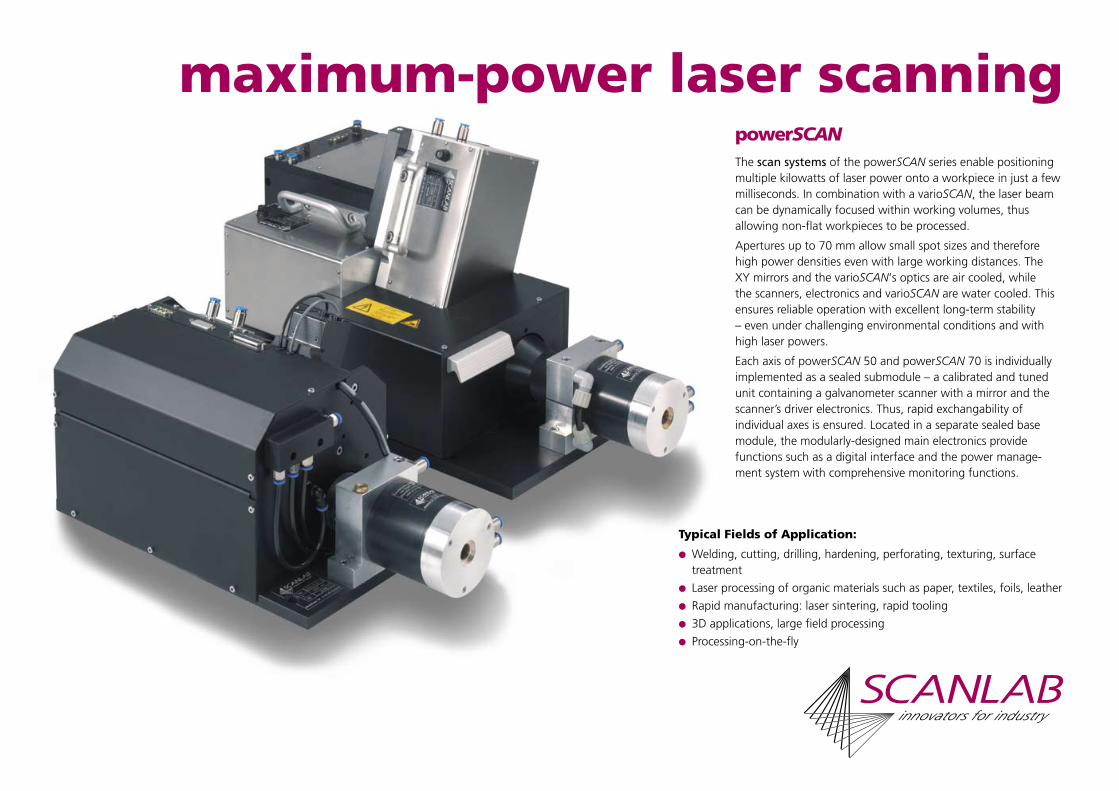
maximum-power laser scanningpowerSCANThe scan systems of the powerSCAN series enable positioning multiple kilowatts of laser power onto a workpiece in just a few milliseconds. In combination with a varioSCAN, the laser beam can be dynamically focused within working volumes, thusallowing non-flat workpieces to be processed.
Apertures up to 70 mm allow small spot sizes and therefore high power densities even with large working distances. The XY mirrors and the varioSCAN‘s optics are air cooled, while the scanners, electronics and varioSCAN are water cooled. This ensures reliable operation with excellent long-term stability – even under challenging environmental conditions and with high laser powers.
Each axis of powerSCAN 50 and powerSCAN 70 is individually implemented as a sealed submodule – a calibrated and tuned unit containing a galvanometer scanner with a mirror and the scanner’s driver electronics. Thus, rapid exchangability ofindividual axes is ensured. Located in a separate sealed base module, the modularly-designed main electronics providefunctions such as a digital interface and the power manage-ment system with comprehensive monitoring functions.
Typical Fields of Application:
Welding, cutting, drilling, hardening, perforating, texturing, surface treatment
Laser processing of organic materials such as paper, textiles, foils, leather
Rapid manufacturing: laser sintering, rapid tooling
3D applications, large field processing
Processing-on-the-fly
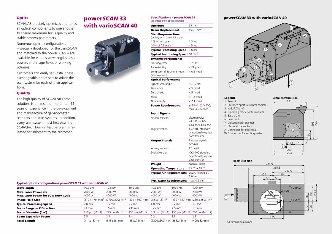
Optics
SCANLAB precisely optimizes and tunes all optical components to one another to ensure maximum focus quality and stable process parameters.
Numerous optical configurations – specially developed for the varioSCAN and matched to the powerSCAN – are available for various wavelengths, laser powers and image fields or working volumes.
Customers can easily self-install these exchangeable optics sets to adapt the scan system for each of their applica-tions.
Quality
The high quality of SCANLAB’s scan solutions is the result of more than 15 years of experience in the development and manufacture of galvanometer scanners and scan systems. In addition, every scan system must first pass the SCANcheck burn-in test before it is re-leased for shipment to the customer.
powerSCAN 33 with varioSCAN 40Specifications – powerSCAN 33(all angles are in optical degrees)
Aperture 33 mm
Beam Displacement 45.21 mm
Step Response Time(settling to 1/1000 of full scale)
1% of full scale 1.3 ms
10% of full scale 4.5 ms
Typical Processing Speed 3 rad/s
Typical Positioning Speed 18 rad/s
Dynamic Performance
Tracking error 0.75 ms
Repeatability < 22 µrad
Long-term drift over 8 hours (after warm-up)
< 0.6 mrad
Optical Performance
Typical scan angle ±0.35 rad
Gain error < 5 mrad
Zero offset < 5 mrad
Skew < 1.5 mrad
Nonlinearity < 2.1 mrad
Power Requirements ±(15+1.5) V DC,max. 4.5 A each
Input Signals
Analog version alternatively:±4.8 V; ±9.6 V;±4.8 mA; ±9.6 mA
Digital version XY2-100 standard or optionally optical data transfer
Output Signals 3 status signals per axis
Analog version TTL level
Digital version XY2-100 standard or optionally optical data transfer
Weight approx. 10 kg
Operating Temperature 25 °C ± 10 °C
Typical Air Requirements clean, filtered air, 1.6 bar
Typ. Water Requirements max. 4.5 bar
powerSCAN 33 with varioSCAN 40
Legend1 Beam in2 Entrance aperture (water-cooled)3 varioSCAN 404 Clamping block (water-cooled)5 Base plate6 Beam out7 Galvanometer scannerE Electrical connectorsA Connector for cooling airW Connectors for cooling water
Typical optical configurations powerSCAN 33 with varioSCAN 40
Wavelength 10.6 µm 10.6 µm 10.6 µm 10.6 µm 1064 nm 1064 nm
Max. Laser Power cwMax. Laser Power for 50% Duty Cycle
2000 W4000 W
2000 W4000 W
2000 W4000 W
2000 W4000 W
2000 W4000 W
2000 W4000 W
Image Field Size (170 x 170) mm2 (270 x 270) mm2 (500 x 500) mm2 (1.5 x 1.5) m2 (130 x 130) mm2 (250 x 250) mm2
Typical Processing Speed 0.8 m/s 1.0 m/s 2.0 m/s 6.0 m/s 0.7 m/s 1.0 m/s
Focus Range in Z Direction ± 4 mm ± 5 mm ± 35 mm ± 75 mm ± 5 mm ± 5 mm
Focus Diameter (1/e2) 210 µm (M2=1) 275 µm (M2=1) 450 µm (M2=1) 1.3 mm (M2=1) 150 µm (M2=12) 200 µm (M2=12)
Beam Expansion Factor 2.5 2.4 2.4 2.2 2.5 2.5
Focal Length (414 ± 15) mm (515 ± 28) mm (850 ± 75) mm (2300 ± 500) mm (365 ± 18) mm (490 ± 32) mm

Legend1 Beam in2 Entrance aperture (water-cooled)3 varioSCAN 604 Clamping block (water-cooled)5 Base plate6 Beam out7, 8 Submodules9 Base module with main electronicsD Fiber connector for optical data
transferP Power supply connectorA Connectors for cooling airW Connectors for cooling water
Specifications – powerSCAN 50(all angles are in optical degrees)
Aperture 50 mm
Beam Displacement 72.72 mm
Step Response Time(settling to 1/1000 of full scale)
1% of full scale 1.5 ms
Typical Processing Speed 2.5 rad/s
Typical Positioning Speed 15 rad/s
Dynamic Performance
Tracking error 0.9 ms
Repeatability < 22 µrad
Long-term drift over 8 hours (after warm-up)
< 0.6 mrad
Optical Performance
Typical scan angle ±0.35 rad
Gain error < 5 mrad
Zero offset < 5 mrad
Skew < 1.5 mrad
Nonlinearity < 2.1 mrad
Power Requirements ±(24+1.5) V DC,max. 10 A each (20 A peak current)
Input Signals optical data transfer or optionallyXY2-100 standard
Output Signals 4 status signals, optical data transfer or optionallyXY2-100 standard
Weight approx. 29 kg
Operating Temperature 25 °C ± 10 °C
Typical Air Requirements clean, filtered air, 1.5 bar to 2.0 bar
Typ. Water Requirements max. 4.5 bar
powerSCAN 50 with varioSCAN 60
powerSCAN 50 with varioSCAN 60
Control
The powerSCAN systems can be con-trolled via a SCANLAB RTC® interface board.This facilitates straight-forward implementation of applications – even complex ones. powerSCAN 50 and powerSCAN 70 scan systems are equipped with interfaces for data transfer via optical fiber.
The RTC® board automatically performs all required computations, such as micro-vectorization and image field cor-rection, and synchronously controls the powerSCAN, varioSCAN and laser.
Processing-on-the-fly functionality is optionally available.
Typical optical configurations powerSCAN 50 with varioSCAN 60
Wavelength 10.6 µm 10.6 µm 10.6 µm 10.6 µm
Max. Laser Power cwMax. Laser Power for 50% Duty Cycle
2000 W4000 W
2000 W4000 W
2000 W4000 W
2000 W4000 W
Image Field Size (400 x 400) mm2 (600 x 600) mm2 (800 x 800) mm2 (1000 x 1000) mm2
Typical Processing Speed 1.3 m/s 2.0 m/s 2.7 m/s 3.2 m/s
Focus Range in Z Direction ± 10 mm ± 40 mm ± 50 mm ± 100 mm
Focus Diameter (1/e2) 250 µm (M2=1) 375 µm (M2=1) 500 µm (M2=1) 600 µm (M2=1)
Beam Expansion Factor 3.8 3.6 3.5 3.4
Focal Length (750 ± 50) mm (1050 ± 90) mm (1350 ± 150) mm (1650 ± 250) mm

powerSCAN 70
06 / 2005 Information is subject to change without notice.
Specifications – powerSCAN 70(all angles are in optical degrees)
Aperture 70 mm
Beam Displacement 98.2 mm
Step Response Time(settling to 1/1000 of full scale)
1% of full scale 2.8 ms
Typical Processing Speed 1.5 rad/s
Typical Positioning Speed 12 rad/s
Dynamic Performance
Tracking error 1.6 ms
Repeatability < 22 µrad
Long-term drift over 8 hours (after warm-up)
< 0.6 mrad
Optical Performance
Typical scan angle ±0.35 rad
Gain error < 5 mrad
Zero offset < 5 mrad
Skew < 1.5 mrad
Nonlinearity < 2.1 mrad
Power Requirements ±(24+1.5) V DC,max. 10 A each (20 A peak current)
Input Signals optical data transfer or optionallyXY2-100 standard
Output Signals 4 status signals, optical data transfer or optionallyXY2-100 standard
Weight approx. 29 kg
Operating Temperature 25 °C ± 10 °C
Typical Air RequirementsMirrorsElectronics
clean, filtered air, 0.9 bar to 1.4 bar0.4 bar to 0.8 bar
Typical Water Requirements
max. 4.5 bar
Options
All powerSCAN systems can be equipped with an additionalreference sensor system for automatic self-calibration for applications requiring extremely high long-term stability.
The powerSCAN 33 can be equipped with sensors for monitoring the cooling air (standard for powerSCAN 50 and powerSCAN 70).
Beryllium mirrors are optionally avail-able for maximized powerSCAN 33 dynamic performance.
Legend1 Beam in2 Beam out3, 4 Submodules5 Base module with
main electronicsD Fiber connector for
optical data transferP Power supply connectorA Connectors for
cooling airW Connectors for
cooling water
SCANLAB AG · Benzstrasse 28 · 82178 Puchheim · GermanyTel. +49 (89) 89 02 58-0 · Fax +49 (89) 89 02 04 62 · [email protected] · www.scanlab.de
SCANLAB America, Inc. · Suite 120 · 11427 Reed Hartman Highway · Cincinnati, OH 45241 · USATel. +1 (513) 618-6425 · Fax +1 (513) 618-6526 · [email protected] · www.scanlab-america.com
Typical optical configurations powerSCAN 70 with varioSCAN 80
Wavelength 10.6 µm 10.6 µm 10.6 µm
Max. Laser Power cwMax. Laser Power for 50% Duty Cycle
2000 W4000 W
2000 W4000 W
2000 W4000 W
Image Field Size (440 x 440) mm2 (1.0 x 1.0) m2 (1.6 x 1.6) m2
Typical Processing Speed 0.9 m/s 2.0 m/s 3.2 m/s
Focus Range in Z Direction ± 10 mm ± 75 mm ± 200 mm
Focus Diameter (1/e2) 220 µm (M2=1) 450 µm (M2=1) 650 µm (M2=1)
Beam Expansion Factor 4.9 4.5 4.6
Focal Length (860 ± 45) mm (1680 ± 200) mm (2440 ± 400) mm
powerSCAN 70
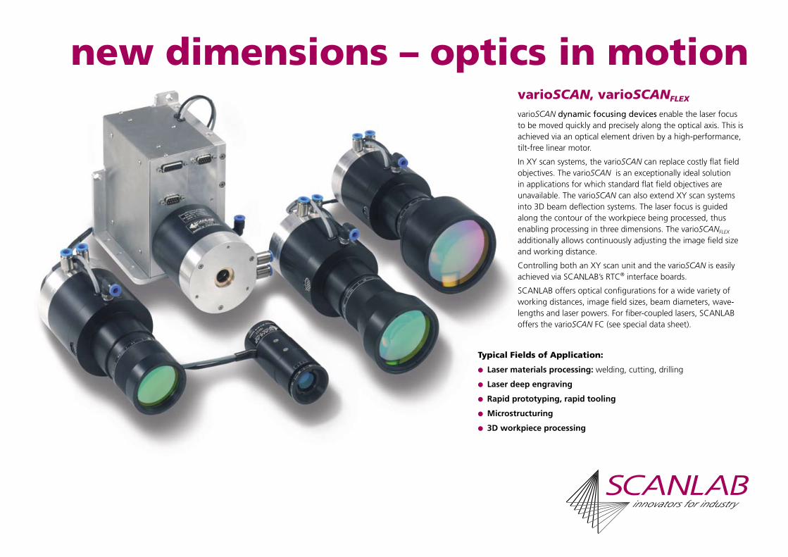
new dimensions – optics in motionvarioSCAN, varioSCANFLEX
varioSCAN dynamic focusing devices enable the laser focus to be moved quickly and precisely along the optical axis. This is achieved via an optical element driven by a high-performance, tilt-free linear motor.
In XY scan systems, the varioSCAN can replace costly flat field objectives. The varioSCAN is an exceptionally ideal solution in applications for which standard flat field objectives are unavailable. The varioSCAN can also extend XY scan systems into 3D beam deflection systems. The laser focus is guided along the contour of the workpiece being processed, thus enabling processing in three dimensions. The varioSCANFLEX additionally allows continuously adjusting the image field size and working distance.
Controlling both an XY scan unit and the varioSCAN is easily achieved via SCANLAB’s RTC® interface boards.
SCANLAB offers optical configurations for a wide variety of working distances, image field sizes, beam diameters, wave-lengths and laser powers. For fiber-coupled lasers, SCANLAB offers the varioSCAN FC (see special data sheet).
Typical Fields of Application:
Laser materials processing: welding, cutting, drilling
Laser deep engraving
Rapid prototyping, rapid tooling
Microstructuring
3D workpiece processing

varioSCAN 20
XY scan systems with apertures up to 20 mm can be extended by the varioSCAN 20 into a 3-axis scan system. The varioSCAN 20 features exceptionally dynamic performance.
Optics are available for laser wavelengths up to 266 nm. For high-laser-power applications, the varioSCAN 20 can be equipped with a water-cooled entrance aperture.
How It Works
The varioSCAN is an opto-mechanical system. Relative to a fixed-position focusing lens, a diverging lens is moved along the optical axis by a tilt-free linear motor (see illustration). This changes the overall system’s focal length. Laser beams of two kilowatts (CO2) or four kilowatts average power (YAG) can be focused.
2D Applications
In an XY scan system, the varioSCAN replaces a flat field objective. During the scan process, the focal length is dynami-cally readjusted in synchronisation with the mirror movement to maintain the laser focus within a flat image field.
3D Applications
A 3-axis system – consisting of a varioSCAN, an XY scan unit and an RTC® interface board – enables processing of non-flat workpieces. The position of the laser focus can be adapted to the contours of the part being processed. Particularly for short focal lengths, the 3-axis scan system can be combined with a flat field objective to achieve the smallest possible spot size and a large focus range in Z direction.
Legend
1 Water-cooled aperture (optional for varioSCAN 20)
2 Motor block
3 Clamping surface
4 Objective adapter
5 Objective
6 Focusing ring
A Connector for cooling air
W Connector for cooling water
All dimensions in mm
Optical Setup varioSCAN 20 with Scan Head
Dimensions varioSCAN 20Specifications varioSCAN 20(all angles are in optical degrees)
Beam Input Aperture up to max. 8 mm
Output Aperture up to max. 20 mm
Dynamic Performance
Tracking error 1.0 ms
Typical processing speed(with XY scan system)
8 rad/s
Typical positioning speed(with XY scan system)
18 rad/s
Electrical Connections (with SSV30)
Power Requirements ±(15+1.5) V DC,max. 1.5 A each
Input Signals
Analog version alternatively:±4.8 V; ±9.6 V;±4.8 mA; ±9.6 mA
Digital version XY2-100 standard or optical data interface
Output Signals status signals
Analog version TTL level
Digital version XY2-100 standard or optical data transfer
Weight
varioSCAN 20 500 g bis 700 g (1)
SSV30 servo amplifier board 190 g
Operating Temperature 25 °C ± 10 °C
Installation Position horizontal(1) depending on optical configuration
Typical 3-axis scan system optical configurations
varioSCAN 20 varioSCAN 40
Laser Nd:YAG x 3 Nd:YAG CO2 Nd:YAG Nd:YAG
Wavelength 355 nm 1064 nm 10.6 µm 1064 nm 1064 nm
XY Scan Unit 10 mm aperture 14 mm aperture 14 mm aperture 20 mm aperture 25 mm aperture
Flat Field Objective without with f = 163 mm with f = 100 mm with f = 163 mm with f = 254 mm
Image Field Size (600 x 600) mm2 (110 x 110) mm2 (70 x 70) mm2 (90 x 90) mm2 (115 x 115) mm2
Focus Range in Z Direction ± 20 mm ± 16 mm ± 7.5 mm ± 5 mm ± 12 mm
Focus Diameter (1/e2) 110 µm (M2=1.3) 110 µm (M2=5) 180 µm (M2=1) 80 µm (M2=5) 100 µm (M2=5)
Beam Expansion Factor 3.8 2.8 3.3 2.8 2.8
Focal Length varioSCAN (1350 ± 60) mm - - - -
Max. Laser Power cw 25 W 200 W 200 W 500 W 500 W

These three varioSCAN employ the same motor unit and therefore exhibit identi-cal dynamics.
Customers can change the varioSCAN 40 / 60 / 80’s image field size by self-installing various optics sets.
Integrated air and water cooling ensure stable operation, even with very high laser powers.
varioSCAN 40 / 60 / 80 Optics
SCANLAB develops and designs the op-tical configurations for varioSCAN and XY scan systems individually, based on the customer’s specific application. Thus, a maximum image field size is achieved with the minimum spot size.
Control
In a 3-axis system, the servo amplifier boards of the varioSCAN and the XY scan system are linked with the RTC® interface board by a common digital interface. The RTC®’s processor performs vital steps such as micro-vectorization, coordinate transformations and image field correction.
QualityThe high quality of SCANLAB’s scan solutions is the result of more than 15 years of experience in the development and manufacture of galvanometer scan-ners and scan systems. In addition, every scan system must first pass a final burn-in test before it is released for shipment to the customer.
Legend
1 Water-cooled aperture (optional for varioSCAN 20)
2 Motor block
3 Clamping surface
4 Objective adapter
5 Objective
6 Focusing ring
A Connector for cooling air
W Connector for cooling water
All dimensions in mm
varioSCAN 40 varioSCAN 60 varioSCAN 80
Total length (Dimension l) (1) ca. 190 mm ca. 220 mm ca. 240 mm
Objective diameter (Dimension d) (1) ca. 60 mm ca. 81 mm ca. 98 mm(1) depending on optical configuration
Optical Setup varioSCAN 40 / 60 / 80 with powerSCAN
Dimensions varioSCAN 40 / 60 / 80 Specifications varioSCAN 40 / 60 / 80(all angles are in optical degrees)
Beam Input Aperture up to max.16 mm
Output Aperture
varioSCAN 40 up to max. 40 mm
varioSCAN 60 up to max. 60 mm
varioSCAN 80 up to max. 80 mm
Dynamic Performance
Tracking error 1.4 ms
Typical processing speed(with XY scan system)
5 rad/s
Typical positioning speed(with XY scan system)
9 rad/s
Electrical Connections (with SSV30)
Power Requirements ±(15+1.5) V DC,max. 1.5 A each
Input Signals
Analog version alternatively:±4.8 V; ±9.6 V;±4.8 mA; ±9.6 mA
Digital version XY2-100 standard or optical data interface
Output Signals status signals
Analog version TTL level
Digital version XY2-100 standard or optical data transfer
Weight
varioSCAN 40 approx. 2.4 kg (1)
varioSCAN 60 approx. 2.7 kg (1)
varioSCAN 80 approx. 3 kg (1)
SSV30 servo amplifier board 190 g
Operating Temperature 25 °C ± 10 °C
Installation Position horizontal(1) depending on optical configuration
varioSCAN 40 varioSCAN 60 varioSCAN 80
CO2 CO2 CO2 CO2 CO2 CO2
10.6 µm 10.6 µm 10.6 µm 10.6 µm 10.6 µm 10.6 µm
33 mm aperture 33 mm aperture 50 mm aperture 50 mm aperture 70 mm aperture 70 mm aperture
without without without without without without
(270 x 270) mm2 (1500 x 1500) mm2 (400 x 400) mm2 (800 x 800) mm2 (1000 x 1000) mm2 (1600 x 1600) mm2
± 5 mm ± 75 mm ± 10 mm ± 50 mm ± 75 mm ± 200 mm
275 µm (M2=1) 1.3 mm (M2=1) 250 µm (M2=1) 500 µm (M2=1) 450 µm (M2=1) 650 µm (M2=1)
2.3 2.2 3.8 3.5 4.5 4.6
(515 ± 28) mm (2300 ± 500) mm (750 ± 50) mm (1350 ± 150) mm (1680 ± 200) mm (2440 ± 400) mm
2000 W 2000 W 2000 W 2000 W 2000 W 2000 W
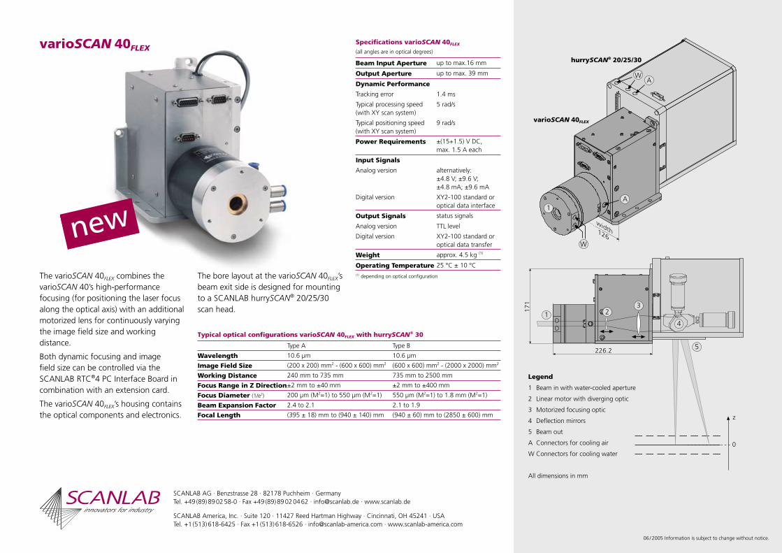
varioSCAN 40FLEX
The varioSCAN 40FLEX combines the varioSCAN 40’s high-performance focusing (for positioning the laser focus along the optical axis) with an additional motorized lens for continuously varying the image field size and working distance.
Both dynamic focusing and image field size can be controlled via the SCANLAB RTC®4 PC Interface Board in combination with an extension card.
The varioSCAN 40FLEX’s housing contains the optical components and electronics.
The bore layout at the varioSCAN 40FLEX’s beam exit side is designed for mounting to a SCANLAB hurrySCAN® 20/25/30 scan head.
06 / 2005 Information is subject to change without notice.
SCANLAB AG · Benzstrasse 28 · 82178 Puchheim · GermanyTel. +49 (89) 89 02 58-0 · Fax +49 (89) 89 02 04 62 · [email protected] · www.scanlab.de
SCANLAB America, Inc. · Suite 120 · 11427 Reed Hartman Highway · Cincinnati, OH 45241 · USATel. +1 (513) 618-6425 · Fax +1 (513) 618-6526 · [email protected] · www.scanlab-america.com
Legend
1 Beam in with water-cooled aperture
2 Linear motor with diverging optic
3 Motorized focusing optic
4 Deflection mirrors
5 Beam out
A Connectors for cooling air
W Connectors for cooling water
All dimensions in mm
varioSCAN 40FLEX
hurrySCAN® 20 / 25 / 30
Specifications varioSCAN 40FLEX
(all angles are in optical degrees)
Beam Input Aperture up to max.16 mm
Output Aperture up to max. 39 mm
Dynamic Performance
Tracking error 1.4 ms
Typical processing speed(with XY scan system)
5 rad/s
Typical positioning speed(with XY scan system)
9 rad/s
Power Requirements ±(15+1.5) V DC,max. 1.5 A each
Input Signals
Analog version alternatively:±4.8 V; ±9.6 V;±4.8 mA; ±9.6 mA
Digital version XY2-100 standard or optical data interface
Output Signals status signals
Analog version TTL level
Digital version XY2-100 standard or optical data transfer
Weight approx. 4.5 kg (1)
Operating Temperature 25 °C ± 10 °C(1) depending on optical configuration
Typical optical configurations varioSCAN 40FLEX with hurrySCAN® 30
Type A Type B
Wavelength 10.6 µm 10.6 µm
Image Field Size (200 x 200) mm2 - (600 x 600) mm2 (600 x 600) mm2 - (2000 x 2000) mm2
Working Distance 240 mm to 735 mm 735 mm to 2500 mm
Focus Range in Z Direction±2 mm to ±40 mm ±2 mm to ±400 mm
Focus Diameter (1/e2) 200 µm (M2=1) to 550 µm (M2=1) 550 µm (M2=1) to 1.8 mm (M2=1)
Beam Expansion Factor 2.4 to 2.1 2.1 to 1.9
Focal Length (395 ± 18) mm to (940 ± 140) mm (940 ± 60) mm to (2850 ± 600) mm

maximum-power laser scanningvarioSCAN FCThe varioSCAN FC is a new type of dynamic focusing unit that can be combined with a powerSCAN to realize a 3D beam deflection system for fiber-coupled multi-kilowatt lasers.
Beam delivery is based on a variable collimator, with optical elements driven by the linAXIS linear axis from SCANLAB. The laser focus can thus be moved quickly and precisely along the optical axis. The beam focus is optimized to remain a virtually constant focus diameter throughout the entire working volume.
Adaptation to various fiber connector types and numerical apertures is possible.
The varioSCAN FC is designed to handle a laser power of up to five kilowatts. To ensure reliable operation also with very high laser powers, the varioSCAN FC is equipped for water cooling.
The varioSCAN FC‘s dynamics and optical layout are designed for use with SCANLAB‘s powerSCAN systems. Both, the varioSCAN FC and the powerSCAN are easily controlled with SCANLAB’s RTC® PC interface boards.
Typical Applications:
Remote welding
Laser materials processing: welding, soldering,surface treatment (hardening, texturing ...)
Rapid manufacturing
3D applications
Processing-on-the-fly

varioSCAN FC
How it works
The varioSCAN FC is an opto-mechanical system consisting of a variable collimator, a beam expander and focusing optics.
The variable collimator‘s optics is dynamically driven along the optical axis by the linAXIS linear axis. This allows the laser beam‘s divergence, and thus the overall system‘s focal length, to be varied.
In addition, there are provisions for manual adjustment of the nominal working distance.
Two deflection mirrors fold the beam path to keep the total system dimensions of the powerSCAN and varioSCAN FC as compact as possible.
SCANLAB offers a variety of optical configurations for adapting the system to the customer’s particular application. Working distance and field size can be adjusted by the selection of focusing optics. By exchanging the fiber adapter or collimator optics the varioSCAN FC can be adapted to various laser types.
Control
In a 3-axis system, the servo amplifier boards of the varioSCAN and the XY scan system are linked with a SCANLAB RTC ® PC interface board by a common digital interface. The RTC ®’s processor performs vital steps such as micro-vectorization, coordinate transfor-mations and image field correction.
Applications
In 2D applications, the varioSCAN – as a dynamic focusing unit – replaces a flat field objective. During the scan process, the focal length is dynamically readjusted to maintain the laser focus within a flat image field.
In 3D applications, the varioSCAN enables processing of non-flat work-pieces. The position of the laser focus can be adapted to the contours of the part being processed.
Preliminary Specificationsfor varioSCAN FC with powerSCAN 50 (all angles are in optical degrees)
Beam Input Coupler direct connection to fiber cable
Connector type Optoskand QBH,Optoskand MMI orTrumpf LLK-B (1)
Numerical aperture 0.12 or 0.20 (1)
Dynamic Performance Tracking error 0.9 msTypical processing speed 2.5 rad/sTypical positioning speed 15 rad/s
Power Requirements ±(24+1.5) V DC,max. 10 A each (20 A peak current)
Interface optical data transfer orXY2-100 standard
Weight approx. 50 kg (2)
Operating Temperature
25 °C ± 10 °C
Typical Water Requirements
max. 4.5 bar
(1) other customizations possible(2) depending on optical configuration
Typical optical configurations with powerSCAN 50
Wavelength Range 1030 nm - 1090 nm
Working Volume (200 x 200 x 100) mm3
Focus Diameter (3) approx. 625 µm
Max. Laser Power cw 5 kW
Working Distance(4) From lower edge 450 mm
From protective window 465 mm(3) with the following beam parameter product at the fiber output:
- BPP = 12 mm·mrad (M2 = 36) for top hat intensity profile or
- BPP = 8 mm·mrad (M2 = 24) for gaussian intensity profile(4) distance to central working plane
SCANLAB AG · Benzstrasse 28 · 82178 Puchheim · GermanyTel. +49 (89) 89 02 58-0 · Fax +49 (89) 89 02 04 62 · [email protected] · www.scanlab.de
SCANLAB America, Inc. · Suite 120 · 11427 Reed Hartman Highway · Cincinnati, OH 45241 · USATel. +1 (513) 618-6425 · Fax +1 (513) 618-6526 · [email protected] · www.scanlab-america.com
07 / 2004 Information is subject to change without notice.
Legend
1 Fiber cable * 2 Fiber connector *3 Fiber adapter4 Variable collimator with
linAXIS linear axis5 Beam expander6 Focusing optics7 powerSCAN 508 Base plate
* not included

control and versatilitySCANLAB’s RTC® PC interface boards provide synchronous, interference-resistant control of scan systems and lasers in real time.
A high-performance signal processor and the supplied DLL simplify pro-gramming under Windows. Alternatively, industry-proven software pack-ages from various third-party vendors are also available for handling a palette of standard applications.
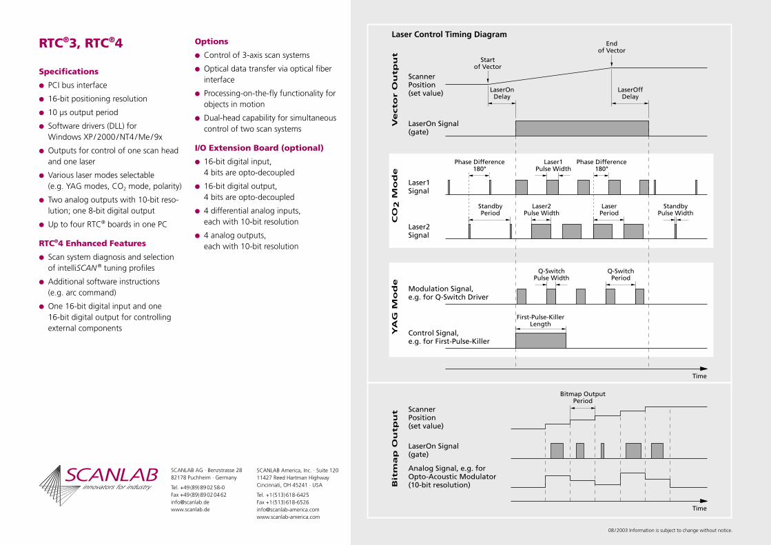
Software instructions are loaded alternately in the RTC®’s two list buffers, processed by the DSP, and output as 16-bit control signals every 10 µs to the scan system. The RTC®’s processor automatically performs vital steps such as micro-vectorization and image field correction. Laser control is synchronized with the scanner movements. Various programmable laser signals are available for vector and bitmap processing (see diagram on reverse side).
The RTC®4 is downward-compatible with the RTC®3. Additionally, the RTC®4 is capable of communicating with the processors onboard SCAN-LAB’s new intelliSCAN ® scan heads – thus, it furnishes to the control PC the real-time stream of scan head axis status parameters and enables extensive scan system diagnosis possibilities. Optimized intelliSCAN ® scan head tuning profiles for diverse processing tasks can be selected via soft-ware commands. Compared to the RTC®3, the RTC®4 offers more memory, faster performance and additional software instructions (e.g. arc com-mand). For controlling external components, the RTC®4 provides 16 digital input ports and 16 digital output ports.
SCANLAB’s RTC® PC interface boards are available with numerous options, providing the extensive flexibility system integrators need for meeting di-verse customer requirements. Furthermore, an I/O extension board is avail-able for controlling additional external components.
RTC®3, RTC®4
RTC®3, RTC®4
Specifications
PCI bus interface
16-bit positioning resolution
10 µs output period
Software drivers (DLL) for Windows XP / 2000 / NT4 / Me / 9x
Outputs for control of one scan head and one laser
Various laser modes selectable (e.g. YAG modes, CO2 mode, polarity)
Two analog outputs with 10-bit reso-lution; one 8-bit digital output
Up to four RTC® boards in one PC
RTC®4 Enhanced Features
Scan system diagnosis and selection of intelliSCAN ® tuning profiles
Additional software instructions (e.g. arc command)
One 16-bit digital input and one 16-bit digital output for controlling external components
Options
Control of 3-axis scan systems
Optical data transfer via optical fiber interface
Processing-on-the-fly functionality for objects in motion
Dual-head capability for simultaneous control of two scan systems
I/O Extension Board (optional)
16-bit digital input, 4 bits are opto-decoupled
16-bit digital output, 4 bits are opto-decoupled
4 differential analog inputs,each with 10-bit resolution
4 analog outputs, each with 10-bit resolution
08 / 2003 Information is subject to change without notice.
SCANLAB AG · Benzstrasse 2882178 Puchheim · Germany
Tel. +49 (89) 89 02 58-0Fax +49 (89) 89 02 04 [email protected] www.scanlab.de
SCANLAB America, Inc. · Suite 12011427 Reed Hartman HighwayCincinnati, OH 45241 · USA
Tel. +1 (513) 618-6425Fax +1 (513) [email protected]

independent control RTC® SCANaloneSCANLAB’s RTC® SCANalone Board enables real-time control of scan systems and lasers without requiring a PC. The board’s high-performance signal processor and extensive internal memory make this possible. The only item required for operation is an external power supply.
Marking data can be loaded via a removable MMC memory card or by using the built-in USB 1.1 interface. The board’s internal memory can accommodate up to one million list commands – a capacity that meets the needs of both today’s and tomorrow’s complex applications.
External control signals can be used to start or otherwise influence the execution of applications loaded in memory. For this purpose, the board is equipped with an additional 16-bit digital input and 16-bit digital output.
Control commands to the scan system are issued synchronously every 10 µs as 16-bit digital output signals.
The RTC® SCANalone can also be operated via a PC connected to the board’s USB interface. In this mode, the RTC® SCANalone offers the same functionality as an RTC®4 PC interface board.
The RTC® SCANalone software interface and hardware connection capabilities are largely compatible with those of the RTC®4 PC interface board. All options offered for the RTC®4 PC interface board (e.g. 3D or processing on the fly) are also available for the RTC® SCANalone.

RTC® SCANalone
Specifications
Outputs for controlling a scan head and a laser
Various laser modes selectable (e.g. YAG mode, CO2 mode, polarity)– see illustration
USB 1.1 interface to PC
MMC memory card included
16-bit positioning resolution
10 µs output period
Software driver (DLL) for Windows XP / 2000 andWindows ME / 98
Two 10-bit analog outputs
One 8-bit digital output
One 16-bit digital input and one 16-bit digital output
Two 10-bit analog inputs
Battery-powered clock/calender
PowerOK/BUSY status LED
Power requirement +7...+30 V DC(max. 10 W)
Options
Control of 3-axis scan systems
Optical data transfer via optical fiber interface
Processing-on-the-fly functionality for objects in motion
Dual-head capability for simultaneous control of two scan systems with individual image field correction
Opto-decoupled laser signals
Extension board with D-SUB connectors for easy front panel mounting
19’’ rack-mountable version
01 / 2004 Information is subject to change without notice.
SCANLAB AG · Benzstrasse 2882178 Puchheim · Germany
Tel. +49 (89) 89 02 58-0Fax +49 (89) 89 02 04 [email protected] www.scanlab.de
SCANLAB America, Inc. · Suite 12011427 Reed Hartman HighwayCincinnati, OH 45241 · USA
Tel. +1 (513) 618-6425Fax +1 (513) [email protected]