Embed Size (px)
Citation preview

Document Number: MD00848Revision 1.06
December 10, 2013
Copyright © 2010-2012 MIPS Technologies Inc. All rights reserved.
MIPSVerified
™
microMIPS32® Architecture forProgrammers Volume IV-i: Virtualization
Module of the microMIPS32®Architecture

microMIPS32® Architecture for Programmers Volume IV-i: Virtualization Module of the microMIPS32® Architecture, Revision1.06
Copyright © 2010-2012 MIPS Technologies Inc. All rights reserved.
Template: nB1.03, Built with tags: 2B ARCH IMPL MIPS32 MIPS32andIMPL
Unpublished rights (if any) reserved under the copyright laws of the United States of America and other countries.
This document contains information that is proprietary to MIPS Technologies, Inc. ("MIPS Technologies") one of the Imagination Technologies Group plccompanies. Any copying, reproducing, modifying or use of this information (in whole or in part) that is not expressly permitted in writing by MIPSTechnologies or an authorized third party is strictly prohibited. At a minimum, this information is protected under unfair competition and copyright laws.Violations thereof may result in criminal penalties and fines.
Any document provided in source format (i.e., in a modifiable form such as in FrameMaker or Microsoft Word format) is subject to use and distributionrestrictions that are independent of and supplemental to any and all confidentiality restrictions. UNDER NO CIRCUMSTANCES MAY A DOCUMENTPROVIDED IN SOURCE FORMAT BE DISTRIBUTED TO A THIRD PARTY IN SOURCE FORMAT WITHOUT THE EXPRESS WRITTENPERMISSION OF MIPS TECHNOLOGIES, INC.
MIPS Technologies reserves the right to change the information contained in this document to improve function, design or otherwise. MIPS Technologies doesnot assume any liability arising out of the application or use of this information, or of any error or omission in such information. Any warranties, whetherexpress, statutory, implied or otherwise, including but not limited to the implied warranties of merchantability or fitness for a particular purpose, are excluded.Except as expressly provided in any written license agreement from MIPS Technologies or an authorized third party, the furnishing of this document does notgive recipient any license to any intellectual property rights, including any patent rights, that cover the information in this document.
The information contained in this document shall not be exported, re-exported, transferred, or released, directly or indirectly, in violation of the law of anycountry or international law, regulation, treaty, Executive Order, statute, amendments or supplements thereto. Should a conflict arise regarding the export, re-export, transfer, or release of the information contained in this document, the laws of the United States of America shall be the governing law.
The information contained in this document constitutes one or more of the following: commercial computer software, commercial computer softwaredocumentation, or other commercial items. If the user of this information, or any related documentation of any kind, including related technical data or manuals,is an agency, department, or other entity of the United States government ("Government"), the use, duplication, reproduction, release, modification, disclosure,or transfer of this information, or any related documentation of any kind, is restricted in accordance with Federal Acquisition Regulation 12.212 for civilianagencies and Defense Federal Acquisition Regulation Supplement 227.7202 for military agencies. The use of this information by the Government is furtherrestricted in accordance with the terms of the license agreement(s) and/or applicable contract terms and conditions covering this information from MIPSTechnologies or an authorized third party.
MIPS, MIPS I, MIPS II, MIPS III, MIPS IV, MIPS V, MIPSr3, MIPS32, MIPS64, microMIPS32, microMIPS64, MIPS-3D, MIPS16, MIPS16e, MIPS-Based,MIPSsim, MIPSpro, MIPS-VERIFIED, Aptiv logo, microAptiv logo, interAptiv logo, microMIPS logo, MIPS Technologies logo, MIPS-VERIFIED logo,proAptiv logo, 4K, 4Kc, 4Km, 4Kp, 4KE, 4KEc, 4KEm, 4KEp, 4KS, 4KSc, 4KSd, M4K, M14K, 5K, 5Kc, 5Kf, 24K, 24Kc, 24Kf, 24KE, 24KEc, 24KEf, 34K,34Kc, 34Kf, 74K, 74Kc, 74Kf, 1004K, 1004Kc, 1004Kf, 1074K, 1074Kc, 1074Kf, R3000, R4000, R5000, Aptiv, ASMACRO, Atlas, "At the core of the userexperience.", BusBridge, Bus Navigator, CLAM, CorExtend, CoreFPGA, CoreLV, EC, FPGA View, FS2, FS2 FIRST SILICON SOLUTIONS logo, FS2NAVIGATOR, HyperDebug, HyperJTAG, IASim, iFlowtrace, interAptiv, JALGO, Logic Navigator, Malta, MDMX, MED, MGB, microAptiv, microMIPS,Navigator, OCI, PDtrace, the Pipeline, proAptiv, Pro Series, SEAD-3, SmartMIPS, SOC-it, and YAMON are trademarks or registered trademarks of MIPSTechnologies, Inc. in the United States and other countries.
All other trademarks referred to herein are the property of their respective owners.

3 microMIPS32® Architecture for Programmers Volume IV-i: Virtualization Module of the microMIPS32® Architecture, Revision1.06
Copyright © 2010-2012 MIPS Technologies Inc. All rights reserved.

microMIPS32® Architecture for Programmers Volume IV-i: Virtualization Module of the microMIPS32® Architecture, Revision1.06 4
Copyright © 2010-2012 MIPS Technologies Inc. All rights reserved.
Table of Contents
Chapter 1: About This Book ................................................................................................................ 101.1: Typographical Conventions ....................................................................................................................... 10
1.1.1: Italic Text.......................................................................................................................................... 111.1.2: Bold Text .......................................................................................................................................... 111.1.3: Courier Text ..................................................................................................................................... 11
1.2: UNPREDICTABLE and UNDEFINED ....................................................................................................... 111.2.1: UNPREDICTABLE........................................................................................................................... 111.2.2: UNDEFINED .................................................................................................................................... 121.2.3: UNSTABLE ...................................................................................................................................... 12
1.3: Special Symbols in Pseudocode Notation................................................................................................. 121.4: For More Information ................................................................................................................................. 15
Chapter 2: The Virtualization Module of the microMIPS32® Architecture ...................................... 162.1: Base Architecture Requirements............................................................................................................... 162.2: Software Detection of the Module ............................................................................................................. 162.3: Compliance and Subsetting....................................................................................................................... 162.4: Overview of the Virtualization Module ....................................................................................................... 162.5: Instruction Bit Encoding............................................................................................................................. 16
Chapter 3: Overview of Virtualization Support .................................................................................. 223.1: Overview.................................................................................................................................................... 22
Chapter 4: The Virtualization Privileged Resource Architecture ..................................................... 244.1: Introduction................................................................................................................................................ 244.2: Overview.................................................................................................................................................... 244.3: Compliance................................................................................................................................................ 244.4: Operating Modes ....................................................................................................................................... 25
4.4.1: The Onion Model.............................................................................................................................. 264.4.2: Terminology ..................................................................................................................................... 284.4.3: Definition of Guest Mode.................................................................................................................. 284.4.4: The Guest Context ........................................................................................................................... 31
4.5: Virtual Memory .......................................................................................................................................... 344.5.1: Virtualized MMU GuestID Use ......................................................................................................... 394.5.2: Root and Guest Shared TLB Operation ........................................................................................... 424.5.3: Nested Guest CCA Support ............................................................................................................. 43
4.6: Coprocessor 0 ........................................................................................................................................... 434.6.1: New and Modified CP0 Registers .................................................................................................... 444.6.2: New CP0 Instructions....................................................................................................................... 454.6.3: Guest CP0 registers......................................................................................................................... 454.6.4: Guest Privileged Sensitive Features ................................................................................................ 514.6.5: Access Control for Guest CP0 Register Fields ................................................................................ 514.6.6: Guest Config Register Fields ........................................................................................................... 524.6.7: Guest Context Dynamically Set Read-only Fields ........................................................................... 544.6.8: Guest Timer ..................................................................................................................................... 554.6.9: Guest Cache Operations.................................................................................................................. 574.6.10: UNPREDICTABLE and UNDEFINED in Guest Mode.................................................................... 57
5 microMIPS32® Architecture for Programmers Volume IV-i: Virtualization Module of the microMIPS32® Architecture, Revision1.06
Copyright © 2010-2012 MIPS Technologies Inc. All rights reserved.
4.7: Exceptions ................................................................................................................................................. 584.7.1: Exceptions in Guest Mode ............................................................................................................... 584.7.2: Faulting Address for Exceptions from Guest Mode.......................................................................... 604.7.3: Guest initiated Root TLB Exception ................................................................................................. 604.7.4: Exception Priority ............................................................................................................................. 614.7.5: Exception Vector Locations.............................................................................................................. 654.7.6: Synchronous and Synchronous Hypervisor Exceptions .................................................................. 654.7.7: Guest Privileged Sensitive Instruction Exception............................................................................. 664.7.8: Guest Software Field Change Exception ......................................................................................... 674.7.9: Guest Hardware Field Change Exception........................................................................................ 694.7.10: Guest Reserved Instruction Redirect ............................................................................................. 704.7.11: Hypercall Exception ....................................................................................................................... 714.7.12: Guest Exception Code in Root Context ......................................................................................... 71
4.8: Interrupts ................................................................................................................................................... 724.8.1: External Interrupts............................................................................................................................ 744.8.2: Derivation of Guest.CauseIP/RIPL................................................................................................... 794.8.3: Timer Interrupts................................................................................................................................ 804.8.4: Performance Counter Interrupts....................................................................................................... 81
4.9: Instructions and Machine State, other than CP0 ....................................................................................... 824.9.1: General Purpose Registers and Shadow Register Sets .................................................................. 824.9.2: Multiplier Result Registers ............................................................................................................... 844.9.3: DSP Module ..................................................................................................................................... 844.9.4: Floating Point Unit (Coprocessor 1) ................................................................................................. 844.9.5: Coprocessor 2.................................................................................................................................. 854.9.6: MSA (MIPS SIMD Architecture) ....................................................................................................... 854.9.7: User FR Feature .............................................................................................................................. 854.9.8: LL/SC LLbit Handling ....................................................................................................................... 864.9.9: XPA : Extended Physical Address ................................................................................................... 864.9.10: SDBBP Instruction Handling .......................................................................................................... 87
4.10: Combining the Virtualization Module and the MT Module ....................................................................... 874.11: Guest Mode and Debug features ............................................................................................................ 894.12: Watchpoint Debug Support ..................................................................................................................... 904.13: Virtualization Module features and Hypervisor Software......................................................................... 924.14: Lightweight Virtualization......................................................................................................................... 98
4.14.1: Introduction .................................................................................................................................... 984.14.2: Support for Lightweight Virtualization............................................................................................. 98
Chapter 5: Coprocessor 0 (CP0) Registers ...................................................................................... 1025.1: CP0 Register Summary........................................................................................................................... 1025.2: GuestCtl0 Register (CP0 Register 12, Select 6) ..................................................................................... 1035.3: GuestCtl1 Register (CP0 Register 10, Select 4) ..................................................................................... 1115.4: GuestCtl2 Register (CP0 Register 10, Select 5) ..................................................................................... 1125.5: GuestCtl3 Register (CP0 Register 10, Select 6) ..................................................................................... 1155.6: GuestCtl0Ext Register (CP0 Register 11, Select 4) ................................................................................ 1165.7: GTOffset Register (CP0 Register 12, Select 7)....................................................................................... 1195.8: Cause Register (CP0 Register 13, Select 0) ........................................................................................... 1205.9: Configuration Register 3 (CP0 Register 16, Select 3) ............................................................................. 1215.10: WatchHi Register (CP0 Register 19)..................................................................................................... 1225.11: Performance Counter Register (CP0 Register 25) ................................................................................ 1225.12: BadVAddr Register (CP0 Register 8, Select 0) ..................................................................................... 1255.13: EntryHi Register (CP0 Register 10, Select 0)........................................................................................ 1265.14: Note on future CP0 features.................................................................................................................. 127

microMIPS32® Architecture for Programmers Volume IV-i: Virtualization Module of the microMIPS32® Architecture, Revision1.06 6
Copyright © 2010-2012 MIPS Technologies Inc. All rights reserved.
Chapter 6: Instruction Descriptions.................................................................................................. 1286.1: Overview.................................................................................................................................................. 128
HYPCALL .................................................................................................................................................... 131MFGC0........................................................................................................................................................ 132MFHGC0 ..................................................................................................................................................... 133MTGC0........................................................................................................................................................ 134MTHGC0 ..................................................................................................................................................... 136TLBGINV..................................................................................................................................................... 137TLBGINVF................................................................................................................................................... 139TLBGP......................................................................................................................................................... 142TLBGR ........................................................................................................................................................ 145TLBGWI....................................................................................................................................................... 147TLBGWR..................................................................................................................................................... 149TLBINVF...................................................................................................................................................... 151TLBINV........................................................................................................................................................ 153TLBP ........................................................................................................................................................... 154TLBR ........................................................................................................................................................... 156TLBWI ......................................................................................................................................................... 159
Chapter 7: Notes ................................................................................................................................. 1627.1: Potential areas of improvement............................................................................................................... 162
Appendix A: Revision History ........................................................................................................... 164
7 microMIPS32® Architecture for Programmers Volume IV-i: Virtualization Module of the microMIPS32® Architecture, Revision1.06
Copyright © 2010-2012 MIPS Technologies Inc. All rights reserved.
List of Figures
Figure 4.1: State Transitions between Operating Modes........................................................................................ 26Figure 4.2: Virtualization Module Onion Model ....................................................................................................... 26Figure 4.3: Virtualization Module Onion Model and exceptions.............................................................................. 27Figure 4.4: Simplified processor operation in root mode......................................................................................... 33Figure 4.5: Virtualization Module Onion Model applied to simplified processor (full virtualization)......................... 34Figure 4.6: Outline of Address Translation.............................................................................................................. 36Figure 4.7: Root and Guest Timers......................................................................................................................... 57Figure 4.8: Interrupts in the Virtualization Module onion model .............................................................................. 73Figure 4.9: Guest and Root CauseIP (non-EIC) Virtualization................................................................................ 76Figure 4.10: A MT Module processor equipped with three VPEs ........................................................................... 88Figure 4.11: A MT Module processor equipped with three VPEs and the Virtualization Module ............................ 88Figure 5.1: GuestCtl0 Register Format ................................................................................................................. 103Figure 5.2: GuestCtl1 Register Format ................................................................................................................. 112Figure 5.3: GuestCtl2 Register Format for non-EIC mode.................................................................................... 112Figure 5.4: GuestCtl2 Register Format for EIC mode........................................................................................... 113Figure 5.5: GuestCtl3 Register Format ................................................................................................................. 116Figure 5.6: GuestCtl0Ext Register Format ............................................................................................................ 116Figure 5.7: GTOffset Register Format................................................................................................................... 120Figure 5.8: Virtualization Module Cause Register Format .................................................................................... 120Figure 5-9: Config3 Register Format..................................................................................................................... 121Figure 5-10: WatchHi Register Format ................................................................................................................. 122Figure 5-11: Performance Counter Control Register Format ................................................................................ 123Figure 5-12: BadVAddr Register Format............................................................................................................... 125Figure 5-13: EntryHi Register Format ................................................................................................................... 126
microMIPS32® Architecture for Programmers Volume IV-i: Virtualization Module of the microMIPS32® Architecture, Revision1.06 8
Copyright © 2010-2012 MIPS Technologies Inc. All rights reserved.
List of Tables
Table 1.1: Symbols Used in Instruction Operation Statements............................................................................... 12Table 2.1: Symbols Used in the Instruction Encoding Tables................................................................................. 17Table 2.2: microMIPS32 Encoding of Major Opcode Field in Virtualization Module ............................................... 17Table 2.3: POOL32A Encoding of Minor Opcode Field in Virtualization Module .................................................... 18Table 2.4: POOL32Axf Encoding of Minor Opcode Extension Field in Virtualization Module................................. 18Table 2-1: POOL32Axp Encoding of Minor Opcode Extension Field in Virtualization Module ............................... 19Table 2.5: POOL32S Encoding of Minor Opcode Field .......................................................................................... 19Table 2.6: POOL32Sxf Encoding of Minor Opcode Extension Field....................................................................... 20Table 4.1: Guest, Root and Debug modes ............................................................................................................. 30Table 4.2: GuestID Translation Related Usage Mode Control................................................................................ 40Table 4.3: GuestID Use by TLB instructions. .......................................................................................................... 41Table 4.4: Guest Nested CCA ................................................................................................................................ 43Table 4.5: CP0 Registers Introduced by the Virtualization Module......................................................................... 44Table 4.6: CP0 Registers Modified by the Virtualization Module ............................................................................ 45Table 4.7: CP0 Instructions Introduced by the Virtualization Module...................................................................... 45Table 4.8: CP0 Registers in Guest CP0 context ..................................................................................................... 46Table 4.9: Root Modification of Guest CP0 Configuration ...................................................................................... 49Table 4.10: Guest CP0 Fields Subject to Software or Hardware Field Change Exception..................................... 52Table 4.11: Guest CP0 Read-only Config Fields Writable from Root Mode ........................................................... 53Table 4.12: Guest CP0 Read-only Fields Writable from Root Mode....................................................................... 54Table 4.13: Priority of Exceptions ........................................................................................................................... 61Table 4.14: Exception Type Characteristics............................................................................................................ 64Table 4.15: Hypervisor Exception Conditions ......................................................................................................... 65Table 4.16: Root effect on Guest XPA control ........................................................................................................ 86Table 4.17: Virtualization control of SDBBP execution ........................................................................................... 87Table 4.18: Debug Features and Application to Virtualization Module ................................................................... 90Table 4.19: Guest Watchpoint Support ................................................................................................................... 91Table 4.20: Watch Control ...................................................................................................................................... 91Table 4.21: Virtualization Optimizations and their Intended Purpose ..................................................................... 92Table 4.22: MMU Configurations with RPU ............................................................................................................ 99Table 5.1: Virtualization Module Changes to Coprocessor 0 Registers in Numerical Order................................. 102Table 5.2: GuestCtl0 Register Field Descriptions ................................................................................................. 104Table 5.3: GuestCtl0 GExcCode values ............................................................................................................... 110Table 5.4: GuestCtl1 Register Field Descriptions ................................................................................................. 112Table 5.5: non-EIC mode GuestCtl2 Register Field Descriptions ........................................................................ 113Table 5.6: EIC mode GuestCtl2 Register Field Descriptions ............................................................................... 115Table 5.7: GuestCtl3 Register Field Descriptions ................................................................................................. 116Table 5.8: GuestCtl0Ext Register Field Descriptions ............................................................................................ 117Table 5.9: GTOffset Register Field Descriptions................................................................................................... 120Table 5.11: Cause Register ExcCode values ....................................................................................................... 121Table 5.10: Cause Register Field Description, modified by Virtualization Module................................................ 121Table 5.13: WatchHi Register Field Descriptions.................................................................................................. 122Table 5.12: Config3 Register Field Descriptions................................................................................................... 122Table 5.14: New Performance Counter Control Register Field Descriptions ........................................................ 124Table 5.15: BadVAddr Register Field Descriptions............................................................................................... 125Table 5.16: EntryHi Register Field Descriptions ................................................................................................... 126Table 6.1: New and Modified Instructions............................................................................................................. 128

9 microMIPS32® Architecture for Programmers Volume IV-i: Virtualization Module of the microMIPS32® Architecture, Revision1.06
Copyright © 2010-2012 MIPS Technologies Inc. All rights reserved.
Chapter 1
microMIPS32® Architecture for Programmers Volume IV-i: Virtualization Module of the microMIPS32® Architecture, Revision1.06 10
Copyright © 2010-2012 MIPS Technologies Inc. All rights reserved.
About This Book
The microMIPS32® Architecture for Programmers Volume IV-i: Virtualization Module of the microMIPS32®Architecture comes as part of a multi-volume set.
• Volume I-A describes conventions used throughout the document set, and provides an introduction to theMIPS32® Architecture
• Volume I-B describes conventions used throughout the document set, and provides an introduction to themicroMIPS32™ Architecture
• Volume II-A provides detailed descriptions of each instruction in the MIPS32® instruction set
• Volume II-B provides detailed descriptions of each instruction in the microMIPS32™ instruction set
• Volume III describes the MIPS32® and microMIPS32™ Privileged Resource Architecture which defines andgoverns the behavior of the privileged resources included in a MIPS® processor implementation
• Volume IV-a describes the MIPS16e™ Application-Specific Extension to the MIPS32® Architecture. Beginningwith Release 3 of the Architecture, microMIPS is the preferred solution for smaller code size.
• Volume IV-b describes the MDMX™ Application-Specific Extension to the MIPS64® Architecture andmicroMIPS64™. It is not applicable to the MIPS32® document set nor the microMIPS32™ document set. WithRelease 5 of the Architecture, MDMX is deprecated. MDMX and MSA can not be implemented at the sametime.
• Volume IV-c describes the MIPS-3D® Application-Specific Extension to the MIPS® Architecture
• Volume IV-d describes the SmartMIPS®Application-Specific Extension to the MIPS32® Architecture and themicroMIPS32™ Architecture .
• Volume IV-e describes the MIPS® DSP Module to the MIPS® Architecture
• Volume IV-f describes the MIPS® MT Module to the MIPS® Architecture
• Volume IV-h describes the MIPS® MCU Application-Specific Extension to the MIPS® Architecture
• Volume IV-i describes the MIPS® Virtualization Module to the MIPS® Architecture
• Volume IV-j describes the MIPS® SIMD Architecture Module to the MIPS® Architecture
1.1 Typographical Conventions
This section describes the use of italic, bold and courier fonts in this book.
About This Book
11microMIPS32® Architecture for Programmers Volume IV-i: Virtualization Module of the microMIPS32® Architecture, Revision1.06
Copyright © 2010-2012 MIPS Technologies Inc. All rights reserved.
1.1.1 Italic Text
• is used for emphasis
• is used for bits, fields, registers, that are important from a software perspective (for instance, address bits used bysoftware, and programmable fields and registers), and various floating point instruction formats, such as S, D,and PS
• is used for the memory access types, such as cached and uncached
1.1.2 Bold Text
• represents a term that is being defined
• is used for bits and fields that are important from a hardware perspective (for instance, register bits, which arenot programmable but accessible only to hardware)
• is used for ranges of numbers; the range is indicated by an ellipsis. For instance, 5..1 indicates numbers 5 through1
• is used to emphasize UNPREDICTABLE and UNDEFINED behavior, as defined below.
1.1.3 Courier Text
Courier fixed-width font is used for text that is displayed on the screen, and for examples of code and instructionpseudocode.
1.2 UNPREDICTABLE and UNDEFINED
The terms UNPREDICTABLE and UNDEFINED are used throughout this book to describe the behavior of the pro-cessor in certain cases. UNDEFINED behavior or operations can occur only as the result of executing instructions ina privileged mode (i.e., in Kernel Mode or Debug Mode, or with the CP0 usable bit set in the Status register). Unpriv-ileged software can never cause UNDEFINED behavior or operations. Conversely, both privileged and unprivilegedsoftware can cause UNPREDICTABLE results or operations.
1.2.1 UNPREDICTABLE
UNPREDICTABLE results may vary from processor implementation to implementation, instruction to instruction,or as a function of time on the same implementation or instruction. Software can never depend on results that areUNPREDICTABLE. UNPREDICTABLE operations may cause a result to be generated or not. If a result is gener-ated, it is UNPREDICTABLE. UNPREDICTABLE operations may cause arbitrary exceptions.
UNPREDICTABLE results or operations have several implementation restrictions:
• Implementations of operations generating UNPREDICTABLE results must not depend on any data source(memory or internal state) which is inaccessible in the current processor mode
• UNPREDICTABLE operations must not read, write, or modify the contents of memory or internal state whichis inaccessible in the current processor mode. For example, UNPREDICTABLE operations executed in usermode must not access memory or internal state that is only accessible in Kernel Mode or Debug Mode or inanother process

1.3 Special Symbols in Pseudocode Notation
microMIPS32® Architecture for Programmers Volume IV-i: Virtualization Module of the microMIPS32® Architecture, Revision1.06 12
Copyright © 2010-2012 MIPS Technologies Inc. All rights reserved.
• UNPREDICTABLE operations must not halt or hang the processor
1.2.2 UNDEFINED
UNDEFINED operations or behavior may vary from processor implementation to implementation, instruction toinstruction, or as a function of time on the same implementation or instruction. UNDEFINED operations or behaviormay vary from nothing to creating an environment in which execution can no longer continue. UNDEFINED opera-tions or behavior may cause data loss.
UNDEFINED operations or behavior has one implementation restriction:
• UNDEFINED operations or behavior must not cause the processor to hang (that is, enter a state from whichthere is no exit other than powering down the processor). The assertion of any of the reset signals must restore theprocessor to an operational state
1.2.3 UNSTABLE
UNSTABLE results or values may vary as a function of time on the same implementation or instruction. UnlikeUNPREDICTABLE values, software may depend on the fact that a sampling of an UNSTABLE value results in alegal transient value that was correct at some point in time prior to the sampling.
UNSTABLE values have one implementation restriction:
• Implementations of operations generating UNSTABLE results must not depend on any data source (memory orinternal state) which is inaccessible in the current processor mode
1.3 Special Symbols in Pseudocode Notation
In this book, algorithmic descriptions of an operation are described as pseudocode in a high-level language notationresembling Pascal. Special symbols used in the pseudocode notation are listed in Table 1.1.
Table 1.1 Symbols Used in Instruction Operation Statements
Symbol Meaning
← Assignment
=, ≠ Tests for equality and inequality
|| Bit string concatenation
xy A y-bit string formed by y copies of the single-bit value x
b#n A constant value n in base b. For instance 10#100 represents the decimal value 100, 2#100 represents thebinary value 100 (decimal 4), and 16#100 represents the hexadecimal value 100 (decimal 256). If the "b#"prefix is omitted, the default base is 10.
0bn A constant value n in base 2. For instance 0b100 represents the binary value 100 (decimal 4).
0xn A constant value n in base 16. For instance 0x100 represents the hexadecimal value 100 (decimal 256).
xy..z Selection of bits y through z of bit string x. Little-endian bit notation (rightmost bit is 0) is used. If y is lessthan z, this expression is an empty (zero length) bit string.
+, − 2’s complement or floating point arithmetic: addition, subtraction

About This Book
13microMIPS32® Architecture for Programmers Volume IV-i: Virtualization Module of the microMIPS32® Architecture, Revision1.06
Copyright © 2010-2012 MIPS Technologies Inc. All rights reserved.
*, × 2’s complement or floating point multiplication (both used for either)
div 2’s complement integer division
mod 2’s complement modulo
/ Floating point division
< 2’s complement less-than comparison
> 2’s complement greater-than comparison
≤ 2’s complement less-than or equal comparison
≥ 2’s complement greater-than or equal comparison
nor Bitwise logical NOR
xor Bitwise logical XOR
and Bitwise logical AND
or Bitwise logical OR
not Bitwise inversion
&& Logical (non-Bitwise) AND
<< Logical Shift left (shift in zeros at right-hand-side)
>> Logical Shift right (shift in zeros at left-hand-side)
GPRLEN The length in bits (32 or 64) of the CPU general-purpose registers
GPR[x] CPU general-purpose register x. The content of GPR[0] is always zero. In Release 2 of the Architecture,GPR[x] is a short-hand notation for SGPR[ SRSCtlCSS, x].
SGPR[s,x] In Release 2 of the Architecture and subsequent releases, multiple copies of the CPU general-purpose regis-ters may be implemented. SGPR[s,x] refers to GPR set s, register x.
FPR[x] Floating Point operand register x
FCC[CC] Floating Point condition code CC. FCC[0] has the same value as COC[1].
FPR[x] Floating Point (Coprocessor unit 1), general register x
CPR[z,x,s] Coprocessor unit z, general register x, select s
CP2CPR[x] Coprocessor unit 2, general register x
CCR[z,x] Coprocessor unit z, control register x
CP2CCR[x] Coprocessor unit 2, control register x
COC[z] Coprocessor unit z condition signal
Xlat[x] Translation of the MIPS16e GPR number x into the corresponding 32-bit GPR number
BigEndianMem Endian mode as configured at chip reset (0 →Little-Endian, 1 → Big-Endian). Specifies the endianness ofthe memory interface (see LoadMemory and StoreMemory pseudocode function descriptions), and the endi-anness of Kernel and Supervisor mode execution.
BigEndianCPU The endianness for load and store instructions (0 → Little-Endian, 1 → Big-Endian). In User mode, thisendianness may be switched by setting the RE bit in the Status register. Thus, BigEndianCPU may be com-puted as (BigEndianMem XOR ReverseEndian).
ReverseEndian Signal to reverse the endianness of load and store instructions. This feature is available in User mode only,and is implemented by setting the RE bit of the Status register. Thus, ReverseEndian may be computed as(SRRE and User mode).
Table 1.1 Symbols Used in Instruction Operation Statements (Continued)
Symbol Meaning

1.3 Special Symbols in Pseudocode Notation
microMIPS32® Architecture for Programmers Volume IV-i: Virtualization Module of the microMIPS32® Architecture, Revision1.06 14
Copyright © 2010-2012 MIPS Technologies Inc. All rights reserved.
LLbit Bit of virtual state used to specify operation for instructions that provide atomic read-modify-write. LLbit isset when a linked load occurs and is tested by the conditional store. It is cleared, during other CPU operation,when a store to the location would no longer be atomic. In particular, it is cleared by exception return instruc-tions.
I:,I+n:,I-n:
This occurs as a prefix to Operation description lines and functions as a label. It indicates the instructiontime during which the pseudocode appears to “execute.” Unless otherwise indicated, all effects of the currentinstruction appear to occur during the instruction time of the current instruction. No label is equivalent to atime label of I. Sometimes effects of an instruction appear to occur either earlier or later — that is, during theinstruction time of another instruction. When this happens, the instruction operation is written in sectionslabeled with the instruction time, relative to the current instruction I, in which the effect of that pseudocodeappears to occur. For example, an instruction may have a result that is not available until after the nextinstruction. Such an instruction has the portion of the instruction operation description that writes the resultregister in a section labeled I+1.The effect of pseudocode statements for the current instruction labelled I+1 appears to occur “at the sametime” as the effect of pseudocode statements labeled I for the following instruction. Within one pseudocodesequence, the effects of the statements take place in order. However, between sequences of statements fordifferent instructions that occur “at the same time,” there is no defined order. Programs must not depend on aparticular order of evaluation between such sections.
PC The Program Counter value. During the instruction time of an instruction, this is the address of the instruc-tion word. The address of the instruction that occurs during the next instruction time is determined by assign-ing a value to PC during an instruction time. If no value is assigned to PC during an instruction time by anypseudocode statement, it is automatically incremented by either 2 (in the case of a 16-bit MIPS16e instruc-tion) or 4 before the next instruction time. A taken branch assigns the target address to the PC during theinstruction time of the instruction in the branch delay slot.In the MIPS Architecture, the PC value is only visible indirectly, such as when the processor stores therestart address into a GPR on a jump-and-link or branch-and-link instruction, or into a Coprocessor 0 registeron an exception. The PC value contains a full 32-bit address all of which are significant during a memory ref-erence.
ISA Mode In processors that implement the MIPS16e Application Specific Extension or the microMIPS base architec-tures, the ISA Mode is a single-bit register that determines in which mode the processor is executing, as fol-lows:
In the MIPS Architecture, the ISA Mode value is only visible indirectly, such as when the processor stores acombined value of the upper bits of PC and the ISA Mode into a GPR on a jump-and-link or branch-and-linkinstruction, or into a Coprocessor 0 register on an exception.
PABITS The number of physical address bits implemented is represented by the symbol PABITS. As such, if 36 phys-
ical address bits were implemented, the size of the physical address space would be 2PABITS = 236 bytes.
FP32RegistersMode Indicates whether the FPU has 32-bit or 64-bit floating point registers (FPRs). It is optional if the FPU has32 64-bit FPRs in which 64-bit data types are stored in any FPR.
microMIPS64 implementations have a compatibility mode in which the processor references the FPRs as ifit were a microMIPS32 implementation. In such a case FP32RegisterMode is computed from the FR bit inthe Status register. If this bit is a 0, the processor operates as if it had 32 32-bit FPRs. If this bit is a 1, the pro-cessor operates with 32 64-bit FPRs.The value of FP32RegistersMode is computed from the FR bit in the Status register.
Table 1.1 Symbols Used in Instruction Operation Statements (Continued)
Symbol Meaning
Encoding Meaning
0 The processor is executing 32-bit MIPS instructions
1 The processor is executing MIIPS16e or microMIPSinstructions

About This Book
15microMIPS32® Architecture for Programmers Volume IV-i: Virtualization Module of the microMIPS32® Architecture, Revision1.06
Copyright © 2010-2012 MIPS Technologies Inc. All rights reserved.
1.4 For More Information
Various MIPS RISC processor manuals and additional information about MIPS products can be found at the MIPSURL: http://www.mips.com
For comments or questions on the MIPS32® Architecture or this document, send Email to [email protected].
InstructionInBranchDe-laySlot
Indicates whether the instruction at the Program Counter address was executed in the delay slot of a branchor jump. This condition reflects the dynamic state of the instruction, not the static state. That is, the value isfalse if a branch or jump occurs to an instruction whose PC immediately follows a branch or jump, but whichis not executed in the delay slot of a branch or jump.
SignalException(excep-tion, argument)
Causes an exception to be signaled, using the exception parameter as the type of exception and the argumentparameter as an exception-specific argument). Control does not return from this pseudocode function—theexception is signaled at the point of the call.
Table 1.1 Symbols Used in Instruction Operation Statements (Continued)
Symbol Meaning

Chapter 2
microMIPS32® Architecture for Programmers Volume IV-i: Virtualization Module of the microMIPS32® Architecture, Revision1.06 16
Copyright © 2010-2012 MIPS Technologies Inc. All rights reserved.
The Virtualization Module of the microMIPS32®Architecture
2.1 Base Architecture Requirements
The Virtualization Application-Specific Extension (Module) requires the following base architecture support:
• The microMIPS32 Architecture: The Virtualization Module requires a compliant implementation of themicroMIPS32 Architecture, Release 5.00 or later.
• A TLB-based MMU is required.
• Coprocessor 0 registers KScratch1 and KScratch2 are required
2.2 Software Detection of the Module
Software can determine if the Virtualization Module is implemented by checking the state of the VZ bit in theConfig3 CP0 register.
2.3 Compliance and Subsetting
The Virtualization Module to the microMIPS32 Architecture provides hardware support for software-controlled plat-form virtualization. A subset of Virtualization Module instructions and registers must be implemented, but certaininstructions and machine state are defined to be optional and may be omitted.
2.4 Overview of the Virtualization Module
The Virtualization Module extends the microMIPS32® Architecture with a set of new instructions and machine state,and makes backward-compatible modifications to existing microMIPS32 features.The Virtualization Module isdesigned to enable full virtualization of operating systems.
2.5 Instruction Bit Encoding
Table 2.2 through Table 2.4 describe the instruction encodings used for the Virtualization Module. Table 2.1describes the meaning of the symbols used in the tables. These tables only list the instruction encodings for the Virtu-alization Module instructions. See Volume II-B of this multi-volume set for a full encoding of all instructions.

The Virtualization Module of the microMIPS32® Architecture
17microMIPS32® Architecture for Programmers Volume IV-i: Virtualization Module of the microMIPS32® Architecture, Revision1.06
Copyright © 2010-2012 MIPS Technologies Inc. All rights reserved.
Table 2.1 Symbols Used in the Instruction Encoding Tables
Symbol Meaning
∗ Operation or field codes marked with this symbol are reserved for future use. Executing such aninstruction must cause a Reserved Instruction Exception.
δ (Also italic field name.) Operation or field codes marked with this symbol denotes a field class.The instruction word must be further decoded by examining additional tables that show values foranother instruction field.
β Operation or field codes marked with this symbol represent a valid encoding for a higher-orderMIPS ISA level. Executing such an instruction must cause a Reserved Instruction Exception.
θ Operation or field codes marked with this symbol are available to licensed MIPS partners. To avoidmultiple conflicting instruction definitions, MIPS Technologies will assist the partner in selectingappropriate encodings if requested by the partner. The partner is not required to consult with MIPSTechnologies when one of these encodings is used. If no instruction is encoded with this value,executing such an instruction must cause a Reserved Instruction Exception (SPECIAL2 encodingsor coprocessor instruction encodings for a coprocessor to which access is allowed) or a Coproces-sor Unusable Exception (coprocessor instruction encodings for a coprocessor to which access isnot allowed).
σ Field codes marked with this symbol represent an EJTAG support instruction and implementationof this encoding is optional for each implementation. If the encoding is not implemented, execut-ing such an instruction must cause a Reserved Instruction Exception. If the encoding is imple-mented, it must match the instruction encoding as shown in the table.
ε Operation or field codes marked with this symbol are reserved for MIPS Modules. If the Module isnot implemented, executing such an instruction must cause a Reserved Instruction Exception.
φ Operation or field codes marked with this symbol are obsolete and will be removed from a futurerevision of the microMIPS32 ISA. Software should avoid using these operation or field codes.
Table 2.2 microMIPS32 Encoding of Major Opcode Field in Virtualization Module
Major MSB..MSB-2
MSB-3..MSB-5
0 1 2 3 4 5 6 7
000 001 010 011 100 101 110 111
0 000 POOL32A δ
1 001 16bit
2 010 16bit
3 011 16bit
4 100
5 101
6 110
7 111

2.5 Instruction Bit Encoding
microMIPS32® Architecture for Programmers Volume IV-i: Virtualization Module of the microMIPS32® Architecture, Revision1.06 18
Copyright © 2010-2012 MIPS Technologies Inc. All rights reserved.
Table 2.3 POOL32A Encoding of Minor Opcode Field in Virtualization Module
Minor bit 5..3
bit 2..0
0 1 2 3 4 5 6 7
000 001 010 011 100 101 110 111
0 000
1 001
2 010
3 011
4 100 POOL32Axpδ POOL32Axf δ
5 101
6 110
7 111
Table 2.4 POOL32Axf Encoding of Minor Opcode Extension Field in Virtualization Module
Extension bit 11..9
bit 8..6 0 1 2 3 4 5 6 7
000 001 010 011 100 101 110 111
0 000
1 001
2 010
3 011
4 100
R2 COP0 R0+ COP0 R1+ MT COP0 R1 COP0 R0+ R1 bit15..12
5 101 TLBGP 0000 0
5 101 TLBGR 0001 1
5 101 TLBGWI 0010 2
5 101 TLBGWR 0011 3
5 101 TLBGINV 0100 4
5 101 TLBGINVF 0101 5
5 101 0110 6
5 101 0111 7
5 101 1000 8
5 101 * * 1001 9
5 101 1010 a

The Virtualization Module of the microMIPS32® Architecture
19microMIPS32® Architecture for Programmers Volume IV-i: Virtualization Module of the microMIPS32® Architecture, Revision1.06
Copyright © 2010-2012 MIPS Technologies Inc. All rights reserved.
5 101 1011 b
5 101 HYPCALL 1100 c
5 101 1101 d
5 101 1110 e
5 101 1111 f
R2+ SMART R1+ SMART R2+ MT
6 110 MFGC0 MTGC0 MFGC0 MTGC0
R2 DSP R2 DSP R1 DSP
7 111
Table 2-1POOL32Axp Encoding of Minor Opcode Extension Field in Virtualization Module
Extension bit 11..9
bit 8..6 0 1 2 3 4 5 6 7
000 001 010 011 100 101 110 111
0 000
1 001
2 010
3 011 MFHC0 MTHC0 MFHGC0 MTHGC0 MFHC0 MTHC0 MFHGC0 MTHGC0
Table 2.5 POOL32S Encoding of Minor Opcode Field
Minor bit 5..3
bit 2..0
0 1 2 3 4 5 6 7
000 001 010 011 100 101 110 111
0 000
1 001
2 010
3 011
4 100 POOL32Sxf δ
5 101
6 110
7 111 * * * * * * * *
Table 2.4 POOL32Axf Encoding of Minor Opcode Extension Field (Continued)in Virtualization Module

2.5 Instruction Bit Encoding
microMIPS32® Architecture for Programmers Volume IV-i: Virtualization Module of the microMIPS32® Architecture, Revision1.06 20
Copyright © 2010-2012 MIPS Technologies Inc. All rights reserved.
Table 2.6 POOL32Sxf Encoding of Minor Opcode Extension Field
Extension bit 11..9
bit 8..6 0 1 2 3 4 5 6 7
000 001 010 011 100 101 110 111
0 000
1 001
2 010
3 011 DMFGC0 DMTGC0 DMFGC0 DMTGC0
4 100
5 101
6 110
7 111

The Virtualization Module of the microMIPS32® Architecture
21microMIPS32® Architecture for Programmers Volume IV-i: Virtualization Module of the microMIPS32® Architecture, Revision1.06
Copyright © 2010-2012 MIPS Technologies Inc. All rights reserved.

Chapter 3
microMIPS32® Architecture for Programmers Volume IV-i: Virtualization Module of the microMIPS32® Architecture, Revision1.06 22
Copyright © 2010-2012 MIPS Technologies Inc. All rights reserved.
Overview of Virtualization Support
3.1 Overview
The Virtualization Module defines a set of extensions to the microMIPS32 Architecture for efficient implementationof virtualized systems.
Virtualization is enabled by software - the key element is a control program known as a Virtual Machine Monitor(VMM) or hypervisor. The hypervisor is in full control of machine resources at all times.
When an operating system (OS) kernel is run within a virtual machine (VM), it becomes a ‘guest’ of the hypervisor.All operations performed by a guest must be explicitly permitted by the hypervisor. To ensure that it remains in con-trol, the hypervisor always runs at a higher level of privilege than a guest operating system kernel.
The hypervisor is responsible for managing access to sensitive resources, maintaining the expected behavior for eachVM, and sharing resources between multiple VMs.
In a traditional operating system, the kernel (or ‘supervisor’) typically runs at a higher level of privilege than userapplications. The kernel provides a protected virtual-memory environment for each user application, inter-processcommunications, IO device sharing and transparent context switching. The hypervisor performs the same basic func-tions in a virtualized system - except that the hypervisor’s clients are full operating systems rather than user applica-tions.
The virtual machine execution environment created and managed by the hypervisor consists of the full Instruction SetArchitecture, including all Privileged Resource Architecture facilities, plus any device-specific or board-specificperipherals and associated registers. It appears to each guest operating system as if it is running on a real machinewith full and exclusive control.
The Virtualization Module enables full virtualization, and is intended to allow VM scheduling to take place whilemeeting real-time requirements, and to minimize costs of context switching between VMs.
Minimum Requirements for Virtualization
The first implementations of platform virtualization used ‘trap-and-emulate’ software techniques, which rely on cer-tain properties of the underlying hardware. To be considered ‘classically virtualizable’ an architecture must have thefollowing characteristics:
• At least two operating modes - including privileged and unprivileged
• System resources can only be controlled through privileged instructions while executing in privileged mode
• Execution of a privileged instruction in unprivileged mode will cause an exception (trap), returning control toprivileged mode software
• Address translation is performed on the entire address space when in unprivileged mode

Overview of Virtualization Support
23microMIPS32® Architecture for Programmers Volume IV-i: Virtualization Module of the microMIPS32® Architecture, Revision1.06
Copyright © 2010-2012 MIPS Technologies Inc. All rights reserved.
In the ‘classic’ approach, the guest operating system kernel is ‘de-privileged’ and is executed in the unprivilegedmode. All privileged operations attempted by the guest will trap back to the hypervisor, which executes in the privi-leged mode. The hypervisor emulates all guest privileged operations, keeps track of the guest view of privileged state,and ensures that the system behaves as expected by the guest. Full address translation allows an unmodified guest ker-nel to execute from its original location in memory, and allows the hypervisor to manage address translation to matchthe expectations of the guest kernel. This approach is also known as ‘trap and emulate’ virtualization.
The base microMIPS32 architecture satisfies all the requirements for classic virtualization, except that address trans-lation is not provided for the entire address space in user mode. User mode programs can only run from kuseg,located in the lower portion of the virtual address space. The kernel is typically compiled to run from kseg0, which islocated in the upper portion of the virtual address space, and is accessible only in kernel mode. An operating systemkernel compiled to work with instructions and data located in kseg0 cannot efficiently execute in user mode.
A Segmentation Control system is available for use by the Virtualization Module. This is a programmable memorysegmentation system defined to support remapping (and therefore virtualization) of the existing fixed segment mem-ory model.
In addition to addressing the minimum requirements for virtualization, the Virtualization Module provides featuresdesigned to reduce the number of hypervisor traps required, and to reduce the length of each hypervisor intervention.
For an outline of virtualization support and for a description of each included feature, see Chapter 4, “TheVirtualization Privileged Resource Architecture” on page 24.
For a description of how each feature is intended to be used by software, see Section 4.13 “Virtualization Modulefeatures and Hypervisor Software”.
For a description of recommended features, see Table 4.8.

Chapter 4
microMIPS32® Architecture for Programmers Volume IV-i: Virtualization Module of the microMIPS32® Architecture, Revision1.06 24
Copyright © 2010-2012 MIPS Technologies Inc. All rights reserved.
The Virtualization Privileged Resource Architecture
4.1 Introduction
The microMIPS32 Privileged Resource Architecture (PRA) defines a set of environments and capabilities on whichthe Instruction Set Architecture operates. This includes definitions of the programming interface and operation of thesystem coprocessor, CP0. The Virtualization Module defines extensions to the microMIPS32 PRA that are desirablefor the execution of guest Operating Systems in a fully virtualized environment. This document describes these exten-sions. It is not intended to be a stand-alone PRA specification, and must be read in the context of the microMIPS32Privileged Resource Architecture specification.
4.2 Overview
The Virtualization Module defines extensions to microMIPS32 which are related to virtualization:
• Guest Operating Mode
• Partial CP0 register set (or context) for Guest Mode use
• Registers for Guest Mode control
• Guest interrupt system
• Two-level address translation
• Detection of Virtualization Features
The Virtualization Module provides a separate Coprocessor 0 register set (or context) for guest mode opera-tion, which is physically separate from, and a subset of the Root Coprocessor 0 context. This Coprocessor 0 con-text is referred to by the term ‘context’ throughout this document.
The presence of the Virtualization Module is indicated by the Config3VZ field.See Section 5.9 “ConfigurationRegister 3 (CP0 Register 16, Select 3)”.
4.3 Compliance
Features described as Required in this document are required of all processors claiming compatibility with the Virtu-alization Module. Any features described as Recommended should be implemented unless there is an overriding neednot to do so. Features described as Optional are features that may or may not be appropriate for a particular Virtual-ization Module processor implementation. If such a feature is implemented, it must be implemented as described inthis document if a processor is to claim compatibility with the Virtualization Module.

The Virtualization Privileged Resource Architecture
25microMIPS32® Architecture for Programmers Volume IV-i: Virtualization Module of the microMIPS32® Architecture, Revision1.06
Copyright © 2010-2012 MIPS Technologies Inc. All rights reserved.
In some cases, there are features within features that have different levels of compliance. For example, if there is anOptional field within a Required register, this means that the register must be implemented, but the field may or maynot be, depending on the needs of the implementation. Similarly, if there is a Required field within an Optional regis-ter, this means that if the register is implemented, it must have the specified field.
4.4 Operating Modes
Fundamental to the Virtualization Module is a limited-privilege guest operating mode. Guest mode consists of newoperating modes guest-kernel, guest-user and guest-supervisor - orthogonal to the existing kernel, user and supervisormodes.
The pre-existing (non-guest) operating mode is known as root mode. The pre-existing kernel, user and supervisoroperating modes can be referred to as root-kernel, root-user and root-supervisor respectively, to distinguish themfrom their guest-mode equivalents.
The guest mode allows the separation between kernel, user and supervisor modes to be retained for a guest operatingsystem running within a virtual machine - the guest-kernel mode can handle interrupts and exceptions, and managevirtual memory for guest-user mode processes.
The separation between root mode and the limited-privilege guest mode allows root mode software to be in full con-trol of the machine at all times even when a guest is running. Backward compatibility is retained for existing softwarerunning in root mode.
The GuestCtl0 register, described in Section 5.2, contains the GM (Guest Mode) bit. This bit is used along withroot-mode exception and error status bits (StatusEXL, StatusERL) and the Debug Mode bit (DebugDM) to determinewhether the processor is operating in guest mode or root mode.
See also Section 4.4.3 “Definition of Guest Mode”.
Figure 4.1 shows the state transitions between operating modes.

4.4 Operating Modes
microMIPS32® Architecture for Programmers Volume IV-i: Virtualization Module of the microMIPS32® Architecture, Revision1.06 26
Copyright © 2010-2012 MIPS Technologies Inc. All rights reserved.
Figure 4.1 State Transitions between Operating Modes
4.4.1 The Onion Model
The Virtualization Module applies an ‘onion model’ to address translation and exception handling for guests. Threeoperating modes are required to execute a virtualized guest operating system: unprivileged guest-user, limited-privi-lege guest-kernel and full-privilege root-kernel. The root-user mode is used to execute non-virtualized software. Ateach layer within the onion, any operation must be permitted by all the outer layers.
Figure 4.3 shows the logical arrangement of operating modes.
Figure 4.2 Virtualization Module Onion Model
In a microMIPS32 processor, Coprocessor 0 contains system control registers, and can be accessed only by privilegedinstructions. A processor implementing the Virtualization Module physically replicates a subset of the Coprocessor 0register set for use by the Guest Operating System. Root mode operation uses one set of Coprocessor 0 registers andGuest mode operation the other. The term ‘context’ refers to the software visible state held within each Coprocessor 0
root-kernel
root-user
guest-kernel
guest-user
Guest-handledIRQs,
IRQ,Exceptions
Reset
HypercallRoot-handled exceptions
eret
eret
eret
Root-handled IRQs
eret IRQs,Exceptions
exceptions
exceptions,hypcall, if Guest.StatusCU0=1
root-user
root-kernel
guest-user
guest-kernel
root Coprocessor 0
guest Coprocessor 0

The Virtualization Privileged Resource Architecture
27microMIPS32® Architecture for Programmers Volume IV-i: Virtualization Module of the microMIPS32® Architecture, Revision1.06
Copyright © 2010-2012 MIPS Technologies Inc. All rights reserved.
register set. The software visible state is the contents of these registers and any state which is accessed via these reg-isters, such as TLB entries and Segmentation Control configurations. For a Hypervisor to save, restore or switch con-text from one guest to another, it is the entire software visible state which must be saved and restored, not solely thereplicated registers themselves, but also the physical resources which are shared between Root and Guest, such as theGPRs, FPRs and Hi/Lo registers.
During guest mode execution, both the guest Coprocessor 0 and the root Coprocessor 0 are active. The presence oftwo simultaneously active Coprocessor 0 contexts is fundamental to the operation of the Virtualization Module.
During guest mode execution, all guest operations are first tested against the guest CP0 context, and then against theroot CP0 context. An ‘operation’ is any process which can trigger an exception - this includes address translation,instruction fetches, memory accesses for data, instruction validity checks, coprocessor accesses and breakpoints.
Exceptions are handled in the mode whose context triggered the exception. An exception triggered by the guest CP0context will be handled in guest mode. An exception triggered by the root CP0 context will be handled in root mode.
Guest mode software has no access to the root Coprocessor 0. Root mode software can access the guest Coprocessor0, and if required can emulate guest-mode accesses to disabled or unimplemented features within guest Coprocessor0. The guest Coprocessor 0 is partially populated - only a subset of the complete root Coprocessor 0 is implemented.
The presence of two Coprocessor 0 contexts allows for an immediate switch between guest and root modes - withoutrequiring a context switch to/from memory. Simultaneously active contexts for the guest and root Coprocessor 0allows guest-kernel privileged code to execute with the minimum hypervisor intervention, and ensures that keyroot-mode machine systems such timekeeping, address translation and external interrupt handling continue to operatewithout major changes during guest execution.
Figure 4.3 shows the how the Virtualization Module ‘onion model’ is applied to operations starting in each of theoperating modes (supervisor modes are omitted for clarity).
Figure 4.3 Virtualization Module Onion Model and exceptions
An operation executed in guest-user mode must travel from the inside of the onion to the outside.
guest-user
guest-kernel root-kernel
Guest CP0
guest-kernel handler root-kernel handler
Complete
root-user
operationexception?
Root CP0exception?
N N
Y Y
operation start point

4.4 Operating Modes
microMIPS32® Architecture for Programmers Volume IV-i: Virtualization Module of the microMIPS32® Architecture, Revision1.06 28
Copyright © 2010-2012 MIPS Technologies Inc. All rights reserved.
The first layer to be crossed is the guest CP0 context (controlled by guest-kernel mode software). All exception andtranslation rules defined by the guest CP0 context are applied, and resulting exceptions taken in guest mode.
If the operation does not trigger a guest-context exception, the next layer to be crossed is the root CP0 context (con-trolled by root-kernel mode software). All exception and translation rules defined by the root CP0 context are applied,and resulting exceptions taken in root mode.
For example, an access to Coprocessor 1 (the Floating Point Unit) must first be permitted by the guest contextStatusCU1 bit, and then by the root context StatusCU1 bit. However, access of guest to Coprocessor 0 is not qualifiedby root context StatusCU0 as Coprocessor 0 state is not shared with root.
External interrupts must travel from the outside of the onion to the inside - first being parsed by the root CP0 context,and if passed on by the hypervisor software, by the guest CP0 context.
4.4.2 Terminology
When executing in guest mode, both the root and guest Coprocessor 0 contexts are in active use. See Section4.4.1 “The Onion Model”. A prefix is used to distinguish between registers located in the guest and root contexts.
For example - Root.Status refers to the status register from the root context, and Guest.Compare refers to the timercompare register in the guest context.
Pseudocode in this document uses object-oriented terminology to describe processes which can be applied to multiplecontexts. A prefix is used to indicate which context is to be operated on by the process. In object-oriented terminol-ogy, the subroutines shown are akin to methods provided by a CP0 class.
For example:# Perform TLB lookup using Root CP0 context# - exceptions taken in root contextRoot.TLBLookup(.., .., ..)
# Perform TLB lookup using Guest CP0 context# - exceptions taken in guest contextGuest.TLBLookup(.., .., ..)
# Perform TLB lookup using context defined by ‘object’ variable# - exceptions taken in ‘object’ contextobject.TLBLookup(.., .., ..)
# Perform TLB lookup using context of the callerTLBLookup(.., .., ..
4.4.3 Definition of Guest Mode
4.4.3.1 Definition
The processor is in guest mode (guest-user, guest-supervisor or guest-kernel) when:
• Root.GuestCtl0GM = 1 and Root.StatusEXL=0 and Root.StatusERL=0 and Root.DebugDM=0.
Guest mode operation is determined as follows. This subroutine will be used in pseudo-code to test whether processoris in guest-mode.
subroutine IsGuestMode() :

The Virtualization Privileged Resource Architecture
29microMIPS32® Architecture for Programmers Volume IV-i: Virtualization Module of the microMIPS32® Architecture, Revision1.06
Copyright © 2010-2012 MIPS Technologies Inc. All rights reserved.
if (GuestCtl0GM=1) and (Root.DebugDM=0) and(Root.StatusERL=0) and (Root.StatusEXL=0) thenreturn(true)
elsereturn(false)
endifendsub
In contrast, the following subroutine is to be used in pseudo-code to test whether processor is in root-mode.subroutine IsRootMode() :
if ((GuestCtl0GM=0) or((GuestCtl0GM=1) and not ((Root.DebugDM=0) and(Root.StatusERL=0) and (Root.StatusEXL=0))) thenreturn(true)
elsereturn(false)
endifendsub
4.4.3.2 Entry to Guest mode
The recommended method of entering Guest mode is by executing an ERET instruction when Root.GuestCtl0GM=1,Root.StatusEXL=1, Root.StatusERL=0 and Root.DebugDM=0.
Instructions executed in root mode use the root context. When an ERET instruction is executed in root mode andRoot.StatusERL=0, the target address is obtained from Root.EPC and the exception-level bit EXL is cleared inRoot.Status. After the ERET instruction execution is completed, the processor will be in guest mode if theRoot.GuestCtl0GM bit was set.
The behavior of ERET, and DERET and their usage of EPC, ErrorEPC and DEPC registers are unchanged from thebase architecture. The determination of Guest vs. Root mode is the result of setting the Root register fieldsGuestCtl0GM, StatusEXL, StatusERL and DebugDM to the Guest mode definition state (Root.GuestCtl0GM = 1 andRoot.StatusEXL=0 and Root.StatusERL=0 and Root.DebugDM=0).
4.4.3.3 Exit from Guest mode
When an interrupt or exception is to be taken in root mode, the bits Root.StatusEXL or Root.StatusERL are set on entry,before any machine state is saved. As a result, execution of the handler will take place in root mode, and root modeexception context registers are used, including Root.EPC, Root.Cause, Root.BadVAddr, Root.Context, Root.EntryHi.
The HYPCALL instruction is provided for controlled guest-to-root transitions. This instruction triggers a HypercallException, taken in root mode. See Section 4.7.11 “Hypercall Exception”.
The ERET instruction cannot be used to enter root mode from guest mode. No root-mode state is accessible fromguest mode, thus the guest cannot change the Root.GuestCtl0, Root.Status or Root.Debug registers.
4.4.3.4 Guest mode execution
When running in guest mode, the distinction between guest-user, guest-supervisor and guest-kernel is made usingGuest.StatusERL, Guest.StatusEXL and Guest.StatusKSU/UM, following the rules described in the base architecture.

4.4 Operating Modes
microMIPS32® Architecture for Programmers Volume IV-i: Virtualization Module of the microMIPS32® Architecture, Revision1.06 30
Copyright © 2010-2012 MIPS Technologies Inc. All rights reserved.
When an interrupt or exception is to be taken in guest mode, the bits Root.StatusEXL or Root.StatusERL remain unal-tered on entry. As a result, execution of the handler will take place in guest mode, and guest mode exception contextregisters are used, including Guest.EPC, Guest.Cause, Guest.BadVAddr, Guest.Context, Guest.EntryHi.
4.4.3.5 Reset
At reset, Root.StatusERL=1, thus a microMIPS32 processor will always start in root mode.
In addition, Root.GuestCtl0GM=0 on reset, ensuring that the operation of existing software is unchanged.
4.4.3.6 Debug Mode
For processors that implement EJTAG, the processor is operating in debug privileged execution mode (Debug Mode)when Root.DebugDM=1. If the processor is running in Debug Mode, it has full access to all resources that are avail-able to Root Kernel Mode operation.
Debug Mode, Root Mode and Guest Mode are mutually exclusive. At any given time, the processor can only be inone of the three modes. Note that Debug mode operates in the Root context, while Guest mode operates in its ownunique context.
4.4.3.7 Fields affecting processor mode
Table 4.1 describes the fields affecting the processor mode.
Table 4.1 Guest, Root and Debug modes
Root Guest
ModeDebugDM StatusERL StatusEXL StatusKSUGuestCtl0
GM StatusERL StatusEXL StatusKSU
1 Don’t care Debug
0 1 Don’t care Root-Kernel
0 1 Don’t care
0 00 0 Don’t care
01 Root-Supervisor
10 Root-User
Don’t care 1 1 Don’t care Guest-Kernel
0 1 Don’t care
0 00
01 Guest-Supervisor
10 Guest-User
Don’t care 11 UNPREDICTABLE
Don’t care 11 Don’t care UNDEFINED

The Virtualization Privileged Resource Architecture
31microMIPS32® Architecture for Programmers Volume IV-i: Virtualization Module of the microMIPS32® Architecture, Revision1.06
Copyright © 2010-2012 MIPS Technologies Inc. All rights reserved.
4.4.4 The Guest Context
The Virtualization Module provides root-mode software with controls over the instructions that can be executed, theregisters which can be accessed, and the interrupts and exceptions which can be taken when in guest mode. Thesecontrols are combined with new exceptions that return control to root mode when intervention is required. The overallintent is to allow guest-mode software to perform the most common privileged operations without root-mode inter-vention - including transitions between guest kernel and guest user mode, controlling the virtual memory system (theTLB) and dealing with interrupt and exception conditions. Controls allows root-mode software to enforce securitypolicies, and allow for virtualized features to be provided using direct access or trap-and-emulate approaches.
The features added by the Virtualization Module are primarily concerned with virtualizing the privileged state of themachine and dealing with related exception conditions. Hence most features are related to guest-mode interactionwith Coprocessor 0. A partially-populated Coprocessor 0 context is added for guest-mode use. See Section4.6.3 “Guest CP0 registers”.
The Virtualization Module provides controls to trigger an exception on any access to Coprocessor 0 from the guest,access to a particular register or registers, or to trigger an exception after a particular field has been changed. SeeSection 5.2 “GuestCtl0 Register (CP0 Register 12, Select 6)”.
The guest Coprocessor 0 context includes its own interrupt system. Root-mode software can directly control guestinterrupt sources, and can also pass through one or more external hardware interrupts to the Guest. Guest mode soft-ware can enable or disable its own interrupts to enforce critical regions. The root-mode interrupt system remainsactive, allowing timer and external interrupts to be dealt with by root-mode handlers at any time. See Section4.8 “Interrupts”.
The guest context includes its own TLB. This is useful for fully virtualized systems, where direct guest access to theTLB is necessary to maintain performance. A two-level address translation system is present, along with the relatedexception system. This system is used to manage guest mode access to virtual and physical memory, and then torelate those accesses to the real machine’s physical memory. See Section 4.5 “Virtual Memory”.
All microMIPS32 unprivileged instructions and registers can be used by guest mode software without restriction.This includes the General Purpose Registers (GPRs) and multiplier result registers hi and lo. See Section4.9 “Instructions and Machine State, other than CP0”.
MIPS defines optional architecture features and Modules which add machine state and instructions to the basemicroMIPS32 architecture. Some examples include the Floating Point Unit, the DSP Module, and the UserLocal reg-ister. The presence of these optional features and Modules within the machine is indicated by read-only configurationbits in the Root.Config0..7 registers.
The Virtualization Module allows implementations to choose which optional features are available to the guest con-text. The optional features available to the guest are indicated by fields in the Guest.Config0..7 registers. An imple-mentation can further choose to allow run-time configuration of the features available to the guest by allowingroot-mode writes to fields in the Guest.Config0..7 registers.
Root-mode software can control guest writes to the Guest.Config registers when GuestCtl0CF=0. This allows Root tocontrol changes to Guest configuration, or be informed of changes to Guest configuration. See Section 4.6.6 “GuestConfig Register Fields”.
The base microMIPS32 architecture includes access controls which allow kernel-mode code to limit access tooptional or Module features. Examples include the StatusCU1 bit and the StatusMX bit. The ‘onion model’ requiresthat both root-mode and guest-mode permissions are applied to guest-mode accesses. For example, access to thefloating point unit must be enabled by the root (Root.StatusCU1) and the guest (Guest.StatusCU1) before excep-

4.4 Operating Modes
microMIPS32® Architecture for Programmers Volume IV-i: Virtualization Module of the microMIPS32® Architecture, Revision1.06 32
Copyright © 2010-2012 MIPS Technologies Inc. All rights reserved.
tion-free accesses can be performed. See Section 4.9.4 “Floating Point Unit (Coprocessor 1)”. There are exceptionsto the onion model, for example the HWREna register only applies in respective context for guest and root operations.
In a fully virtualized system, the virtual machine presented to the guest is a faithful copy of a real machine - all pro-cessor state, instructions, memory and peripherals operate as expected by the guest software.
Figure 4.4 shows a simplified microMIPS32 processor during root mode execution. Shadow register controls deter-mine which General Purpose Register set is used. Multiplier result registers are accessible in user and kernel modes.Address translation is performed using a TLB-based MMU and Segment Configurations. Access to the FPU is con-trolled by kernel-mode software using the StatusCU1 bit. Interrupts can result from external sources or the systemtimer. Exceptions can result from address translation, breakpoints, instruction execution, or serious errors such asNMI, Machine Check or Cache Error.
The example assumes a non-EIC interrupt system, and for reasons of clarity, omits Supervisor modes and Config0..7
registers.

The Virtualization Privileged Resource Architecture
33microMIPS32® Architecture for Programmers Volume IV-i: Virtualization Module of the microMIPS32® Architecture, Revision1.06
Copyright © 2010-2012 MIPS Technologies Inc. All rights reserved.
Figure 4.4 Simplified processor operation in root mode
Figure 4.5 shows the Virtualization Module ‘onion model’ applied to the simplified microMIPS32 processor fromFigure 4.4, for a fully virtualized guest. Guest context shadow register controls determine which General PurposeRegister set is used. Multiplier result registers are accessible in user and kernel modes. Address translation is per-formed first using the guest context (enabled by GuestCtl0AT=1 or 3), then through the root context TLB. Note thatroot context Segment Configurations are not used - the root context TLB translates every address from the guest.
Exceptions detected by the guest context are handled in guest mode - from guest segmentation/translation, guestcoprocessor enables, guest timekeeping, and IRQs - both external sources passed through by the root context, andIRQ sources directly asserted by root-mode software. Exceptions detected by the root context are handled in rootmode - root timekeeping, IRQs, coprocessor enables and second-level address translation, plus new controls overguest behavior.
User Mode
Root-Kernel Mode
GPRs hi, lo
Base Instrs. FPU Instrs. IRQ detectCauseIP7..2StatusIEStatusIM7..2IntlCtlIPTI
TimekeepingCountCompare
Shadow RegsSRSCtlSRSMap
IRQs
StatusCU1
Exceptions
EPCErrorEPCCauseBadVAddr
BreakpointsEJTAG
Memory FPU
NMI, Cache Error,Machine Check
External Debug
Address
SegmentationControl (optional)
EntryLo0,1EntryHiPageMaskPageGrainIndex, Wired
Translation

4.5 Virtual Memory
microMIPS32® Architecture for Programmers Volume IV-i: Virtualization Module of the microMIPS32® Architecture, Revision1.06 34
Copyright © 2010-2012 MIPS Technologies Inc. All rights reserved.
Figure 4.5 Virtualization Module Onion Model applied to simplified processor (full virtualization)
4.5 Virtual Memory
The Virtualization Module includes an option for two levels of address translation to be applied during guest-modeexecution. The Virtualization Module requires that a TLB-based MMU is implemented in the root context.
The Virtualization Module provides a separate CP0 context for guest-mode execution. This context can optionallyinclude segmentation controls and address translation (MMU). The guest MMU can be TLB-based, block addresstranslation (BAT) or fixed mapping (FMT).
Guest-User Mode
Guest-Kernel Mode
Root-Kernel Mode
GPRs hi, lo
Base Instrs. FPU Instrs.
Exceptions
StatusCU1
EPCErrorEPCCauseBadVAddr
IRQ detectCauseIP7..2StatusIEStatusIM7..2IntlCtlIPTI
TimekeepingCountCompare
Shadow SetsSRSCtlSRSMap
IRQ detectCauseIP7..2StatusIEStatusIM7..2IntlCtlIPTI
TimekeepingCountCompare
Shadow RegsSRSCtlSRSMap
+
GTOffset
IRQs
GuestCtl0PIP7..2
StatusCU1
Exceptions
EPCErrorEPCCauseBadVAddr
PIP
BreakpointsEJTAG
Memory FPU
NMI, Cache Error,Machine Check
GuestCtl0{CP0, AT, GT, CFMC, RI, CG}
GPSIGSFC
Hypercall
External Debug
Address
SegmentationControl (optional)
EntryLo0,1EntryHiPageMaskPageGrainIndex, Wired
Translation
GuestCtl0AT=1 or 3
Address
SegmentationControl (optional)
EntryLo0,1EntryHiPageMaskPageGrainIndex, Wired
Translation
GHFC

The Virtualization Privileged Resource Architecture
35microMIPS32® Architecture for Programmers Volume IV-i: Virtualization Module of the microMIPS32® Architecture, Revision1.06
Copyright © 2010-2012 MIPS Technologies Inc. All rights reserved.
In guest mode when guest segmentation and translation are enabled (GuestCtl0AT=1 or 3), two levels of address trans-lation are performed. The first level uses the guest segmentation controls and the guest MMU. This translates anaddress from a Guest Virtual address (GVA) to a Guest Physical Address (GPA). The second level of translation usesthe root TLB, using the GPA in place of the Virtual Address (VA) that would normally be used. This second transla-tion results in a Physical Address (PA). The cache attribute used is that supplied by the guest context. In this secondlevel of translation, exceptions in address translation are handled by Root.
When a TLB-based guest MMU is provided, it is recommended the number of entries be equal to the number ofentries in the root-context TLB used for Guest mappings. The page sizes used in the root-mode TLB must be care-fully considered to allow sufficient control for root-mode software, while maximizing the number of guest-mode TLBentries which are mapped through each root-mode TLB entry. Larger root TLB pages will likely result in better per-formance.
Both the guest and root MMU’s can be active at the same time. We recommend that the Root TLB maintain an ade-quate amount of reserved TLB entries for its own use to avoid cascading TLB evictions (thrashing).
Figure 4.6 shows the outline of address translation in the Virtualization Module.

4.5 Virtual Memory
microMIPS32® Architecture for Programmers Volume IV-i: Virtualization Module of the microMIPS32® Architecture, Revision1.06 36
Copyright © 2010-2012 MIPS Technologies Inc. All rights reserved.
Figure 4.6 Outline of Address Translation
Implementation note: Processor designs incorporating the Virtualization Module and implementing a guest contextMMU are unlikely to perform translation twice on each memory access. A hardware mechanism will be used toensure that a Physical Address can be obtained from a Guest Virtual Address within the CPU pipeline in a singletranslation. The mechanism may use micro-TLBs - for example, on a micro-TLB refill, a guest TLB lookup would befollowed by a root TLB lookup, to produce a one-step GVA-PA translation. Other methods are possible. The systemmust be arranged to allow for efficient execution and to appear to software that two independent translation steps aretaking place for each memory access.
Guest mode segmentation controls and the guest mode MMU have no effect on the root mode address space.
The optional ‘GuestID’ field (GuestCtl1ID or GuestCtl1RID ) represents a unique identifier for Root and all Guest Vir-tual Address spaces. Each Guest’s address space is identified by a unique non-zero GuestID. The GuestID value zerois reserved for Root address space. The GuestCtl1 CP0 register is unique in the Root register space and inaccessible inguest mode. GuestID is an optimization, designed to minimize TLB invalidation overhead on a virtual machine con-text switch and simplify Root access to Guest TLB entries. The implementation of a GuestID is recommended.Implementation complexity can be minimized by reducing the GuestID to 1 bit. This allows the Root TLB to distin-
Virtual Address (VA)
Root CP0segmentation OPTIONAL
Guest CP0segmentation OPTIONAL
Root TLB
Mapped?
Guest TLB
Exception?
Mapped?
Exception?
Root Virtual AddressRoot ASID
YN
YN
N
Root exception
Guest exception
Y
Physical Address (PA)
N
Y
Guest?
MMU
N
Y
enabled?
GuestID=0
N
ASIDGuest
GuestID=N
Y
Guest Physical AddressRoot ASID is ignoredGuestID=N

The Virtualization Privileged Resource Architecture
37microMIPS32® Architecture for Programmers Volume IV-i: Virtualization Module of the microMIPS32® Architecture, Revision1.06
Copyright © 2010-2012 MIPS Technologies Inc. All rights reserved.
guish between Root and Guest Entries, and flush either set of mappings in entirety with the TLBINVF instruction.Alternatively, GuestID can be eliminated by having Root virtual address space shared with Guest physical addresses.
The pseudocode below describes the complete address translation process for the microMIPS32 Virtualization Mod-ule. Segmentation, TLB lookups, hardware TLB refill and second-level address translation are invoked below. Theprocess is described in top-down order - subsequent sections describe the subroutines called. See Section4.5.1 “Virtualized MMU GuestID Use” for description of RAD and DRG terms.
/* Inputs* vAddr - Virtual Address* IorD - Access type - INSTRUCTION or DATA* LorS - Access type - LOAD or STORE* pLevel - Privilege level - USER, SUPER, KERNEL** Outputs* pAddr - physical address* CCA - cache attribute (valid when mapped)** Exceptions: See called functions* Called from guest or root context.*/
subroutine AddressTranslation(vAddr, IorD, LorS, pLevel)
// Initialization.// GuestID is only applicable if GuestCtl0RAD=0. Otherwise GuestID// is ignored (not applicable) in process of address translation.GuestID ← ignored
if (IsGuestMode()) then// This is a Guest Address translation// step 1: Guest Virtual -> Guest Physical Address translationif (GuestCtl0RAD=0)
GuestID ← GuestCtl1IDendif(mapped, addr, CCA) ← AddressDecode(vAddr, pLevel)if (ConfigMT=1 or ConfigMT=4) then // TLB type MMU
if (mapped) thenasid ← Guest.EntryHiASID(addr, CCA) ← Guest.TLBLookup(asid, GuestID, addr, IorD, LorS)
endifelse
if (ConfigMT=0) then# MMU=None case is undefinedUNDEFINED
else# Other MMU type, FMT or BAT. BAT will use LorS.(addr, CCA) ← Guest.OtherMMULookup(addr, CCA, LorS, pLevel)
endifendifif (exception)
Guest Exception// TLB exceptions may include Refill, Invalid, Execute-Inhibit for// Instruction, Refill, Invalid, Modified, Read-Inhibit for Data.

4.5 Virtual Memory
microMIPS32® Architecture for Programmers Volume IV-i: Virtualization Module of the microMIPS32® Architecture, Revision1.06 38
Copyright © 2010-2012 MIPS Technologies Inc. All rights reserved.
// Guest segment map related exceptions may include Address Errorendif
// step 2: Guest Physical -> Root Physical Address translation// if GuestCtl0RAD=0, then guest entry ASID is global in Root TLB.// H/W must set G=1 for guest entry for TLBWI and TLBWR.asid ← Root.EntryHiASIDpAddr ← Root.TLBLookup(asid, GuestID, addr, IorD, LorS)if (exception)
Root Exception// This is a Root exception initiated in guest context// This includes all TLB exceptions.// Segment map Address Error exception not included, as guest does not// lookup root segment map.
endif
else// This is a Root Address translation// Root Virtual -> Root Physical Address translation// If GuestCtl0DRG=1,GuestCtl1RID is non-zero,Root.StatusEXL,ERL=0,// and DebugDM=0, then all root kernel data accesses are mapped and root// SegCtl is ignored.H/W must set G=1 as if the access were for guest.drg_valid ← (GuestCtl0DRG=1 and Root.StatusKSU=00 and Root.StatusEXL=0 andRoot.StatusERL=0 and DebugDM=0 and GuestCtl1RID!=0 and !Instruction)if (drg_valid) then
mapped ← 1addr ← vAddr
else(mapped, addr, CCA) ← AddressDecode(vAddr, pLevel)
endifif (!mapped) then
pAddr ← addrelse if (GuestCtl0RAD=0)
if (Instruction or (!drg_valid))GuestID ← 0
elseGuestID ← GuestCtl1RID
endifendif
asid ← Root.EntryHiASID(pAddr, CCA) ← Root.TLBLookup(asid, GuestID, addr, IorD, LorS)
endifendifif (exception)
Root Exception// Includes all TLB and Segment related exceptions in Root context.// If drg_valid, and access is not by root-kernel,then an Address Error// exception is caused.
endif
return (pAddr,CCA)end
subroutine AddressDecode(vAddr, pLevel) :# Determine whether address is mapped# - if unmapped, obtain physical address and cache attributeif (Config3SC) then

The Virtualization Privileged Resource Architecture
39microMIPS32® Architecture for Programmers Volume IV-i: Virtualization Module of the microMIPS32® Architecture, Revision1.06
Copyright © 2010-2012 MIPS Technologies Inc. All rights reserved.
// optional Segmentation Control based address decode(mapped, addr, CCA) ← SegmentLookup(vAddr, pLevel)
else(mapped, addr, CCA) ← LegacyDecode(vAddr[31:29], pLevel)
endifreturn (mapped, addr, CCA)
endsub
See also Section 4.7.1 “Exceptions in Guest Mode” and Section 4.7.2 “Faulting Address for Exceptions from GuestMode”.
4.5.1 Virtualized MMU GuestID Use
The use of GuestID is optional as specified by the value of GuestCtl0G1. Software can detect presence of GuestCtl1
and thus GuestCtl1ID and GuestCtl1RID by reading GuestCtl0G1.
For an implementation that supports GuestCtl0RAD=0, GuestCtl0G1 must be preset to 1, otherwise GuestCtl0G1 mustbe preset to 0. GuestCtl0RAD is read-only - an implementation can support one or the other, but never both. On theother hand, GuestCtl0DRG is R/W. See Table 5.2 for description of R/W state of DRG and RAD.
GuestCtl1ID is used for guest-mode operation, while GuestCtl1RID is used for root-mode operation. Root addresstranslation assumes GuestID=0 providing GuestCtl0DRG=0.
The Guest TLB may or may not be shared by multiple guests. The Root TLB will be shared by Root and at least oneunique Guest. Options to support dealiasing guest and root entries in Root TLB, and possibly multiple guests in theGuest TLB is described below.
A processor will support one of the two modes below. Software can determine the mode by reading GuestCtl1RAD
described in Table 4.2
1. Dealiasing by GuestID
GuestID is used to dealias multiple guest contexts in both Guest and Root TLB. Specifically, GuestCtl1ID is usedfor guest-mode operation, whereas GuestCtl1RID is used for root-mode operations. A guest or root-mode opera-tion is an instruction or data translation, or TLB instruction.
An implementation may choose to provide direct root-mode access to guest entries (GPA->RPA) in the RootTLB. Direct root-mode access is described by GuestCtl0DRG in Table 4.2. In the absence of this feature, rootwould have to probe the Root TLB with GPA, and subsequently read on match to obtain the RPA. If a missoccurs, then root must walk the guest shadow page tables in memory. Otherwise, with direct access, a miss willresult in a hardware pagewalk, assuming a hardware pagewalker is supported.
Root ASID for guest entries in the Root TLB are ignored because hardware will set the global bit on a write forsuch entries.
2. Dealiasing by Root ASID.
This option should be used if no GuestID is implemented. Software can detect this mode by readingGuestCtl1RAD.

4.5 Virtual Memory
microMIPS32® Architecture for Programmers Volume IV-i: Virtualization Module of the microMIPS32® Architecture, Revision1.06 40
Copyright © 2010-2012 MIPS Technologies Inc. All rights reserved.
Between Guest context-switches, the Guest and Root TLBs must be flushed of current guest context by root soft-ware. Root.EntryHiASID is used to dealias Root from Guest entries in the Root TLB. Root software must maintaina one is to one correspondence between allocated ASID and the unique Guest it represents.
Root ASID for guest entries in the Root TLB are not ignored unless software explicitly sets G=1 for the guestentry.
.
The following pseudo-code indicates how to specify the ASID and GuestID(if present) interface to the Root andGuest TLBs for Guest and Root address translations, as a function of GuestCtl0RAD. A field within a TLB entry needsto be compared with a “Key” as input to the interface to determine whether a match is has occurred.
Guest and Root TLB interfaces for GuestID dealiasing method (GuestCtl0RAD=0):
Guest TLB Interface:if (Instruction or Load or Store)
GuestTLB.Key[GuestID] = GuestCtl1IDendif
Table 4.2 GuestID Translation Related Usage Mode Control
Field Description
GuestCtl0RAD RAD, or “Root ASID Dealias” mode determines the means that a VirtualizedMMU implementation uses to dealias different contexts.
GuestCtl0DRG DRG, or “Direct Root to Guest” access determines whether an implementationwith GuestCtl0RAD=0 provides root kernel the means to access guest entries
directly in the Root TLB for access to guest memory. If GuestCtl0DRG=1 then
GuestCtl1RID must be used. If GuestID for root operation is non-zero, root is
in kernel mode, Root.StatusEXL,ERL=0 and DebugDM=0, then all root kernel
data accesses are mapped, root SegCtl is ignored and Root TLB CCA is used.Access in root mode by other than kernel will cause an address error. H/Wmust set G=1 as if the access were for guest.
Encoding Meaning
0 GuestID used to dealias both Guestand Root TLB entries in Root TLB.
1 Root ASID is used to dealias RootTLB entries, while Guest TLB con-tains only one context at any giventime.
Encoding Meaning
0 Root software cannot access guestentries directly.
1 Root software can access guest entriesdirectly.

The Virtualization Privileged Resource Architecture
41microMIPS32® Architecture for Programmers Volume IV-i: Virtualization Module of the microMIPS32® Architecture, Revision1.06
Copyright © 2010-2012 MIPS Technologies Inc. All rights reserved.
GuestTLB.Key[ASID] = Guest.EntryHiASID
Root TLB Interface:if ( IsRootMode() )
drg_valid ← (GuestCtl0DRG=1 and Root.StatusKSU=00 and Root.StatusEXL=0 andRoot.StatusERL=0 and DebugDM=0 and GuestCtl1RID!=0 and !Instruction)
if (!drg_valid) then// Instruction or Load or StoreRootTLB.Key[GuestID] = 0
else // special mode - root access guest entriesRootTLB.Key[GuestID] = GuestCtl1RID
endifelse // Guest mode
// Instruction or Load or StoreRootTLB.Key[GuestID] = GuestCtl1ID
endifRootTLB.Key[ASID] = Root.EntryHiASID
With GuestCtl0RAD=0, Guest entries in the Root TLB must ignore the ASID. For this reason, if GuestCtlRID!=0, thatis entry is a Guest entry, then Root mode execution of TLBWI and TLBWR sets the entry’s G bit to 1 automatically.Otherwise, for Root entries, TLBWI and TLBWR must set/clear the G bit in accordance with the baseline architec-ture.
Guest and Root TLB interface for Root ASID dealiasing method (GuestCtl0RAD=1) :
Guest TLB Interface:GuestTLB.Key[ASID] = Guest.EntryHiASID
Root TLB Interface:RootTLB.Key[ASID] = Root.EntryHiASID
GuestCtl0DRG has no effect on the Guest and Root address translations if GuestCtl0RAD=1. If GuestCtl0RAD=1, thenGuestCtl0DRG must be read-only as 0.
For more detail on Guest and Root address translation, please refer to pseudo-code in Section 4.5 “Virtual Memory”.
Table 4.3 specifies the association of GuestID with TLB instructions. For supporting information, refer to Section4.6.2 “New CP0 Instructions”.
Table 4.3 GuestID Use by TLB instructions.
TLB OperationGuestID
(GuestCtl1ID/GuestCtl1RID)
TLBGINV GuestCtl1RID
TLBGINVF GuestCtl1RID
TLBGP GuestCtl1RID
TLBGR GuestCtl1RID
TLBGWI GuestCtl1RID
TLBGWR GuestCtl1RID
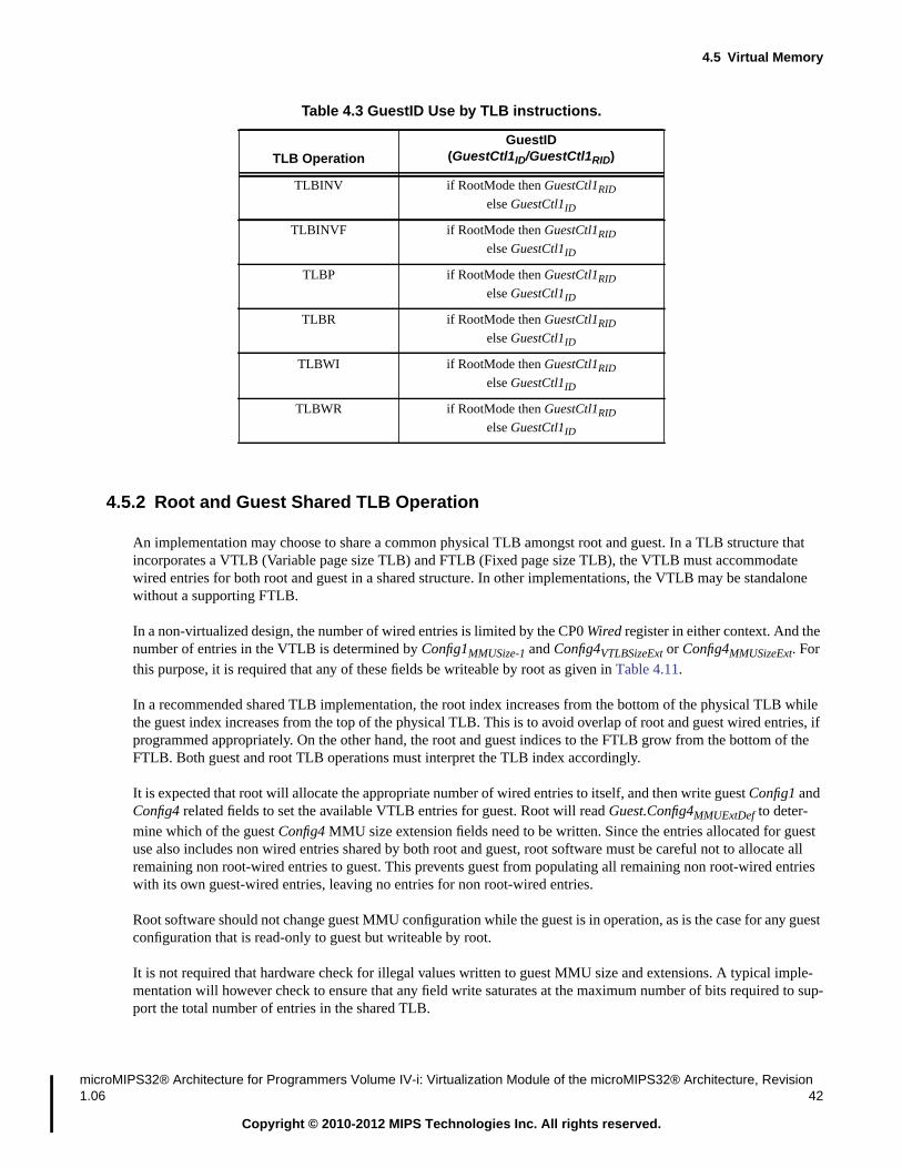
4.5 Virtual Memory
microMIPS32® Architecture for Programmers Volume IV-i: Virtualization Module of the microMIPS32® Architecture, Revision1.06 42
Copyright © 2010-2012 MIPS Technologies Inc. All rights reserved.
4.5.2 Root and Guest Shared TLB Operation
An implementation may choose to share a common physical TLB amongst root and guest. In a TLB structure thatincorporates a VTLB (Variable page size TLB) and FTLB (Fixed page size TLB), the VTLB must accommodatewired entries for both root and guest in a shared structure. In other implementations, the VTLB may be standalonewithout a supporting FTLB.
In a non-virtualized design, the number of wired entries is limited by the CP0 Wired register in either context. And thenumber of entries in the VTLB is determined by Config1MMUSize-1 and Config4VTLBSizeExt or Config4MMUSizeExt. Forthis purpose, it is required that any of these fields be writeable by root as given in Table 4.11.
In a recommended shared TLB implementation, the root index increases from the bottom of the physical TLB whilethe guest index increases from the top of the physical TLB. This is to avoid overlap of root and guest wired entries, ifprogrammed appropriately. On the other hand, the root and guest indices to the FTLB grow from the bottom of theFTLB. Both guest and root TLB operations must interpret the TLB index accordingly.
It is expected that root will allocate the appropriate number of wired entries to itself, and then write guest Config1 andConfig4 related fields to set the available VTLB entries for guest. Root will read Guest.Config4MMUExtDef to deter-mine which of the guest Config4 MMU size extension fields need to be written. Since the entries allocated for guestuse also includes non wired entries shared by both root and guest, root software must be careful not to allocate allremaining non root-wired entries to guest. This prevents guest from populating all remaining non root-wired entrieswith its own guest-wired entries, leaving no entries for non root-wired entries.
Root software should not change guest MMU configuration while the guest is in operation, as is the case for any guestconfiguration that is read-only to guest but writeable by root.
It is not required that hardware check for illegal values written to guest MMU size and extensions. A typical imple-mentation will however check to ensure that any field write saturates at the maximum number of bits required to sup-port the total number of entries in the shared TLB.
TLBINV if RootMode then GuestCtl1RID
else GuestCtl1ID
TLBINVF if RootMode then GuestCtl1RID
else GuestCtl1ID
TLBP if RootMode then GuestCtl1RID
else GuestCtl1ID
TLBR if RootMode then GuestCtl1RID
else GuestCtl1ID
TLBWI if RootMode then GuestCtl1RID
else GuestCtl1ID
TLBWR if RootMode then GuestCtl1RID
else GuestCtl1ID
Table 4.3 GuestID Use by TLB instructions.
TLB OperationGuestID
(GuestCtl1ID/GuestCtl1RID)

The Virtualization Privileged Resource Architecture
43microMIPS32® Architecture for Programmers Volume IV-i: Virtualization Module of the microMIPS32® Architecture, Revision1.06
Copyright © 2010-2012 MIPS Technologies Inc. All rights reserved.
4.5.3 Nested Guest CCA Support
The specification optionally provides the ability for root CCA, in the 2nd step of guest address translation, to modifyguest CCAs.
As specified, nesting is specifically recommended if the hypervisor allows guest to access device addresses, or mem-ory-mapped I/O addresses. It is possible for a rogue guest to store data in the cache as writeback using a cacheableCCA, with this data later on being evicted in another guest’s operating context, with the intent of corrupting a periph-eral. The hypervisor would allow guest access assuming that the system MMU is programmed correctly to selectivelyallow guest access to device address ranges. However such a system MMU would not have the capability of prevent-ing writeback data from accessing the peripheral as it either allows read/write access on a per guest basis and does notfurther differentiate the access.
Nesting is not required if the hypervisor traps and emulates all guest accesses to I/O address ranges.
In either case, guest access to physical memory does not require the application of nesting, as the Root MMU protectssuch accesses on a per guest page basis. However, hypervisor may always apply the policies given in Table 4.4.
See Table 5.8 for definition of related configuration, GuestCtl0ExtNCC.
4.6 Coprocessor 0
Defined by the microMIPS32 Privileged Resource Architecture (PRA), Coprocessor 0 (CP0) contains system controlregisters. Access to these registers is restricted and can only be performed using privileged instructions.
The Virtualization Module provides a partial set of CP0 registers for use by the guest, this is known as the guest con-text. When in guest mode, the behavior of the machine is controlled by the combination of the guest CP0 context andthe root CP0 context. When in root mode, the behavior of the machine is controlled entirely by the root CP0 context.
Table 4.4 Guest Nested CCA
Root CCA Guest CCA
ResultantGuest CCA Changed? Comment
1st step ofguest address
translation
2nd step ofguest address
translation
not UC or UCA Any Unchanged
UC UC UC Unchanged
UC1
1. UC - Uncacheable CCA, Architecturally defined.
WB/WT2
2. WB/WT (Writeback/ Writethru) - Cacheable CCA, Implementation defined.
UC Unchanged Protects against WB to device address
UC UCA UC Unchanged Possible performance impact for guestUCA
UCA3
3. UCA - Uncacheable Accelerated CCA, Implementation defined.
UC UC Unchanged
UCA WB/WT UCA Changed Store gathering may occur on cache-able accesses
UCA UCA UCA Unchanged No performance impact

4.6 Coprocessor 0
microMIPS32® Architecture for Programmers Volume IV-i: Virtualization Module of the microMIPS32® Architecture, Revision1.06 44
Copyright © 2010-2012 MIPS Technologies Inc. All rights reserved.
The guest CP0 context consists of a base set plus optional features.
Access to features within the guest CP0 context is controlled from root mode. The Guest.Config0-7 registers deter-mine which architecture features are active during guest mode execution. The GuestCtl0 register controls whether aguest access to a privileged feature will trigger an exception.
Guest CP0 registers can be accessed from root mode by using the root-only MFGC0 and MTGC0 instructions. GuestTLB contents can be accessed by using the root-only TLBGP, TLBGR, TLBGWI and TLBGWR instructions.
Root context software (hypervisor) is required to manage the initial state of writable Guest context registers. Onpower-up, the initial state defaults to the hardware reset state as defined in the base architecture. On Guest contextsave and restore, the hypervisor is required to preserve and re-initialize the Guest state. For virtual boot of a Guest,the hypervisor is required to initialize the Guest state equivalent to the hardware reset state.
Root has the ability to define the presence of and control the contents of Guest CP0 registers. Therefore, if so config-ured, Guest access to guest CP0 state may cause a Guest Privileged Sensitive Instruction exception. Refer to Table4.8, Section 4.6.6 “Guest Config Register Fields” and Section 4.7.7 “Guest Privileged Sensitive InstructionException” for further information.
Root may deconfigure guest CP0 registers by writing to guest configuration registers as defined in Table 4.11. Guestbehavior in response to these modifications is defined in Table 4.9.
The Virtualization Module requires that scratch registers KScratch1 and KScratch2 are present in the root context.This ensures that hypervisor exception handlers have an adequate number of scratch registers to save and restore allgeneral purpose registers in use by the guest.
4.6.1 New and Modified CP0 Registers
Coprocessor 0 registers are added by the Virtualization Module to control the guest context - GuestCtl0, GuestCtl1and GTOffset.
Table 4.5 describes CP0 registers introduced by the Virtualization Module.
Table 4.5 CP0 Registers Introduced by the Virtualization Module
RegisterNumber Sel
RegisterName Description Reference
ComplianceLevel
12 6 GuestCtl0 Controls guest mode behavior. Section 5.2 Required
10 4 GuestCtl1 Guest ID Section 5.3 Optional
10 5 GuestCtl2 Virtual Interrupts Section 5.4 Optional
10 6 GuestCtl3 Virtual Shadow Sets Section 5.5 Optional
11 4 GuestCtl0Ext Extension to GuestCtl0 Section 5.6 Optional
12 7 GTOffset Offset for guest timer value Section 5.7 Required

The Virtualization Privileged Resource Architecture
45microMIPS32® Architecture for Programmers Volume IV-i: Virtualization Module of the microMIPS32® Architecture, Revision1.06
Copyright © 2010-2012 MIPS Technologies Inc. All rights reserved.
Table 4.6 describes CP0 registers modified by the Virtualization Module.
4.6.2 New CP0 Instructions
The Virtualization Module introduces new instructions for root mode access to the guest CP0 context, and for a guestto make a call into root mode - a ‘hypervisor call’.
Table 4.7 describes CP0 instructions introduced by the Virtualization Module.
4.6.3 Guest CP0 registers
The Virtualization Module provides a partial set of CP0 registers for use by the guest, this is known as the guest con-text. Many guest context registers are optional or can be disabled under software control.
As in the base architecture, fields in Guest.Config, Guest.Config1..7 registers define the architectural capabilities ofthe guest context. When a CP0 register does not exist in the guest context, or is disabled by a root-writableGuest.Config field, it can have no effect on guest behavior. See Section 4.6.6 “Guest Config Register Fields” forinformation on guest Config register fields which can be dynamically reconfigured by Root. Note that accesses toGuest CP0 registers in certain cases will trigger a Guest Privileged Sensitive Instruction (GPSI) exception as definedin Table 4.8.
Table 4.6 CP0 Registers Modified by the Virtualization Module
RegisterNumber Sel
RegisterName Description Reference
ComplianceLevel
13 0 Cause Addition of hypervisor cause code. Section 5.8 Required
16 3 Config3 Identifies Virtualization Module feature set. Section 5.9 Required
19 0 WatchHi Added support for Guest Watch. Section 5.10 Optional
25 0 PerfCnt Added support for Root/Guest performance count. Section 5.11 Optional
8 0 BadVAddr 32-bit extension of BadVAddr for XPA. Section 5.12 Optional
10 0 EntryHi 32-bit extension of EntryHi for XPA. Section 5.13 Optional
31 2 KScratch1 Required in root context. - Required
31 3 KScratch2 Required in root context. - Required
Table 4.7 CP0 Instructions Introduced by the Virtualization Module
Instruction Description ReferenceCompliance
Level
HYPCALL Hypercall - call to root mode. “HYPCALL” on page 131 Required
MFGC0 Move from Guest CP0 “MFGC0” on page 132
MTGC0 Move to Guest CP0 “MTGC0” on page 134
TLBGINV Guest TLB Invalidate “TLBGINV” on page 137 Optional
TLBGINVF Guest TLB Invalidate Flush “TLBGINVF” on page 139 Optional
TLBGP Probe Guest TLB “TLBGP” on page 142 Requiredwhen guestTLB present
TLBGR Read Guest TLB “TLBGR” on page 145
TLBGWI Write Guest TLB “TLBGWI” on page 147
TLBGWR Write Random to Guest TLB “TLBGWR” on page 149

4.6 Coprocessor 0
microMIPS32® Architecture for Programmers Volume IV-i: Virtualization Module of the microMIPS32® Architecture, Revision1.06 46
Copyright © 2010-2012 MIPS Technologies Inc. All rights reserved.
When a CP0 register is defined in the guest context, it is used to control guest execution. Fields in the GuestCtl0 reg-ister can be used to cause Guest Privileged Sensitive Instruction exceptions when an access from guest mode isattempted. This allows hypervisor software to control the value of a register in the guest CP0 context (thus controllingguest-mode execution) while denying guest-kernel access to the register. See Section 4.6.4 “Guest PrivilegedSensitive Features”.
Attempting modification of certain fields in guest context CP0 registers triggers a Guest Software Field Changeexception. In a similar manner, the Guest Hardware Field Change exception is triggered when a hardware initiatedchange to Guest CP0 registers occurs. These mechanisms are used to support Root recognition of Guest initiatedchanges to guest context CP0 registers. This is done to properly manage the operation of the guest virtual machine.See Section 4.6.5 “Access Control for Guest CP0 Register Fields”.
Table 4.8 lists the base architecture CP0 registers noting which may be implemented in the guest context.
Definitions of terms used in Table 4.8:
• Required - Must be implemented in the Guest context.
• Recommended - Should be implemented in the Guest context.
• Optional - Implementation dependent as to whether included in the Guest context.
• Not Available - Never implemented in the Guest context.
The guest CP0 context must include all CP0 registers from an optional feature or an Module if the associatedGuest.Config field indicates that the feature or Module is available in the guest context. For any of these registers,guest access may be controlled by Root software. This is done by triggering a Guest Privileged Sensitive InstructionException on a guest-mode access. Guest Software Field Change and Guest Hardware Field Change exceptions canalso be used.
See also Section 4.9.10 “SDBBP Instruction Handling”.
Table 4.8 CP0 Registers in Guest CP0 context
RegisterNumber Sel Register Name
Available toGuest-Kernel software
when
Guest PrivilegedSensitive Instruction
Exception whenRoot.GuestCtl0CP0=0,
orCompliance
Level
0 0 Index Guest.ConfigMT=1 or
Guest.ConfigMT=4
GuestCtl0ExtMG=1 Required forGuest context
TLB1 0 Random
2 0 EntryLo0
3 0 EntryLo1
4 0 Context
4 1 ContextConfig Guest.Config3SM=1 or
Guest.Config3CTXTC=1
Optional
4 2 UserLocal Guest.Config3ULRI=1 GuestCtl0ExtOG=1 Recom-mended
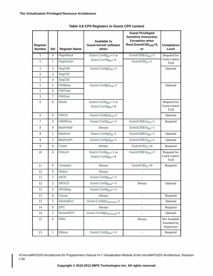
The Virtualization Privileged Resource Architecture
47microMIPS32® Architecture for Programmers Volume IV-i: Virtualization Module of the microMIPS32® Architecture, Revision1.06
Copyright © 2010-2012 MIPS Technologies Inc. All rights reserved.
5 0 PageMask Guest.ConfigMT=1 or
Guest.ConfigMT=4
GuestCtl0ExtMG=1 Required forGuest context
TLB5 1 PageGrain GuestCtl0AT=1
5 2 SegCtl0 Guest.Config3SC=1 Optional
5 3 SegCtl1
5 4 SegCtl2
5 5 PWBase Guest.Config3PW=1 Optional
5 6 PWField
5 7 PWSize
6 0 Wired Guest.ConfigMT=1 or
Guest.ConfigMT=4
Required forGuest context
TLB
6 6 PWCtl Guest.Config3PW=1 Optional
7 0 HWREna Guest.ConfigAR>=1 GuestCtl0ExtOG=1 Required
8 0 BadVAddr Always GuestCtl0ExtBG=1
8 1 BadInstr Guest.Config3BI=1 GuestCtl0ExtBG=1 Optional
8 2 BadInstrP Guest.Config3BP=1 GuestCtl0ExtBG=1 Optional
9 0 Count Always GuestCtl0GT=0 Required
10 0 EntryHi Guest.ConfigMT=1 or
Guest.ConfigMT=4
GuestCtl0ExtMG=1 Required forGuest context
TLB
11 0 Compare Always GuestCtl0GT=0 Required
12 0 Status Always -
12 1 IntCtl Guest.ConfigAR>=1 -
12 2 SRSCtl Guest.ConfigAR>=1 Always Optional
12 3 SRSMap Guest.ConfigAR>=1
13 0 Cause Always - Required
13 5 NestedExc Guest.Config5NFExists=1 - Optional
14 0 EPC Always - Required
14 2 NestedEPC Guest.Config5NFExists=1 - Optional
15 0 PRid - Always Not AvailableEmulated byHypervisor
15 1 EBase Guest.ConfigAR>=1 - Required
Table 4.8 CP0 Registers in Guest CP0 context
RegisterNumber Sel Register Name
Available toGuest-Kernel software
when
Guest PrivilegedSensitive Instruction
Exception whenRoot.GuestCtl0CP0=0,
orCompliance
Level

4.6 Coprocessor 0
microMIPS32® Architecture for Programmers Volume IV-i: Virtualization Module of the microMIPS32® Architecture, Revision1.06 48
Copyright © 2010-2012 MIPS Technologies Inc. All rights reserved.
15 2 CDMMBase Guest.Config3CDMM=1 Always Not AvailableEmulated byHypervisor15 3 CMGCRBase Guest.Config3CMGCR=1
16 0 Config Always On write access whenGuestCtl0CF=0.
Required
16 1 Config1 Guest.ConfigM=1
16 2 Config2 Guest.Config1M=1
16 3 Config3 Guest.Config2M=1
16 4 Config4 Guest.Config3M=1
16 5 Config5 Guest.Config4M=1
16 6 Config6 Implementation dependent - Optional
16 7 Config7
17 0 LLAddr GuestCtl0ExtOG=1 Optional1
17 1 MAAR Guest.Config5MRP=1 Always Not AvailableRelease 5
17 2 MAARI Guest.Config5MRP=1 Always Not AvailableRelease 5
18 0 WatchLo Guest.Config1WR=1 Conditional, refer to Section4.12 “Watchpoint Debug
Support”
Optional
19 0 WatchHi Guest.Config1WR=1
23 0 Debug Guest.Config1EP=1 Always Not Available
24 0 DEPC Guest.Config1EP=1
25 0-n PerfCnt Guest.Config1PC=1 Conditional, refer to Section4.8.4 “PerformanceCounter Interrupts”
26 0 ErrCtl - Always
27 0 CacheErr
28 0 TagLo
28 1 DataLo
28 2 TagLo
28 3 DataLo
29 0 TagHi
29 1 DataHi
29 2 TagHi
29 3 DataHi
30 0 ErrorEPC Always2 - Required
31 0 DESAVE Guest.Config1EP=1 Always Not Available
Table 4.8 CP0 Registers in Guest CP0 context
RegisterNumber Sel Register Name
Available toGuest-Kernel software
when
Guest PrivilegedSensitive Instruction
Exception whenRoot.GuestCtl0CP0=0,
orCompliance
Level

The Virtualization Privileged Resource Architecture
49microMIPS32® Architecture for Programmers Volume IV-i: Virtualization Module of the microMIPS32® Architecture, Revision1.06
Copyright © 2010-2012 MIPS Technologies Inc. All rights reserved.
Table 4.8 indicates the conditions under which guest access of guest CP0 registers can cause a Guest Privileged Sen-sitive Instruction exception (GPSI) to Root. If a GPSI is taken for a guest CP0 register which may or may not beactive in guest mode, the corresponding root CP0 register must be implemented. This is true because the guest CP0context is always a subset of the root CP0 context. Otherwise, access to the corresponding guest CP0 register isUNPREDICTABLE.
If the configuration of a Guest accessible CP0 register can be modified by Root, then Guest access behavior is asspecified in Table 4.9.
Root should not modify Guest configuration while the Guest is running. It is assumed that the Guest software willread its configuration registers during boot and not thereafter. Since Root can modify guest configuration, Rootshould maintain a copy of guest configuration at hardware reset so that it knows which guest CP0 registers are actu-ally implemented. Once modified by Root, the guest configuration registers may not accurately reflect the physicalexistence of guest CP0 registers.
31 2 KScratch1 AlwaysDefined by
Guest.Config4KScrExist
GuestCtl0ExtOG=1 Optional
31 3 KScratch2
31 4 KScratch3
31 5 KScratch4
31 6 KScratch5
31 7 KScratch6
1. LLAddr may optionally be implemented providing the Guest context has access to Guest PhysicalAddresses, else Not Available.
2. ErrorEPC is required in guest context because it used as scratch by some MIPS compatible OSes.
Table 4.9 Root Modification of Guest CP0 Configuration
RegisterReplicated in
GuestContext?
GuestConfiguration
register bitRoot writeableas per Table
4.11
GuestConfigurationRegister bit
value on reset
GuestConfigurationRegister bitvalue after
write by Root,if writeable Interpretation of Configuration
No No 0 N/A The register does not exist in Guest. Reads and writes to thisregister are UNDEFINED.
Yes No 1 N/A The register is replicated in the Guest. Guest can access its ver-sion of the register without traps to Root excluding the cases
identified in Table 4.8
No Yes 0 0 The register exists in Root and is not replicated in the Guestcontext. In Guest mode, reads and writes to this register are
UNDEFINED.
Table 4.8 CP0 Registers in Guest CP0 context
RegisterNumber Sel Register Name
Available toGuest-Kernel software
when
Guest PrivilegedSensitive Instruction
Exception whenRoot.GuestCtl0CP0=0,
orCompliance
Level

4.6 Coprocessor 0
microMIPS32® Architecture for Programmers Volume IV-i: Virtualization Module of the microMIPS32® Architecture, Revision1.06 50
Copyright © 2010-2012 MIPS Technologies Inc. All rights reserved.
4.6.3.1 Guest Reserved Register Handling
This section defines the behaviour of guest access to reserved CP0 registers of different types.
1. Reserved for Architecture. These are CP0 registers reserved by the privileged architecture for future use.
2. Reserved for Implementation. These are CP0 registers reserved for implementations which may or may not bepresent in guest context.
The list of registers is CP0 Register 9 (Selects 6 and 7), Register 11 (Selects 6 and 7), Register 16 (Selects 6 and7), Register 22 (all Selects).
The behaviour of Reserved for Architecture registers follows.
if (GuestCtl0CP0=0) {
<GPSI>} elsif (GuestCtl0ExtOG=1) {
<GPSI>} elsif (is_MFC0) {
MF(H)C0 is UNPREDICTABLE} else { // is_MTC0
MT(H)C0 is UNPREDICTABLE}
A recommended UNPREDICTABLE response is for an MF(H)C0 to return 0s, and for an MT(H)C0 to be dropped.
Release 5 of the architecture introduces extensions to 32-bit CP0 registers. The following distinction applies to han-dling of a CP0 register and its extension.
• A CP0 register may exist but not be extended. An MT(F)HC0 should be treated as if the extension were Reservedfor Architecture.
No Yes 0 1 The register exists in Root and is not replicated in the Guestcontext. In Guest mode, reads and writes to this register throw a
GPSI exception which allows Root to selectively emulate theregister. Registers which conform to this definition are theWatch Registers (4.12) and Performance Registers (5.11).
Yes Yes 1 1 The register exists in the Root context and is replicated in theGuest context. Guest can access its version of the register with-
out exception excluding cases identified in Table 4.8
Yes Yes 1 0 The register exists in the Root context and is replicated in theGuest context. Guest access to the register is disabled. Readsand writes to the register are UNDEFINED.
Table 4.9 Root Modification of Guest CP0 Configuration
RegisterReplicated in
GuestContext?
GuestConfiguration
register bitRoot writeableas per Table
4.11
GuestConfigurationRegister bit
value on reset
GuestConfigurationRegister bitvalue after
write by Root,if writeable Interpretation of Configuration

The Virtualization Privileged Resource Architecture
51microMIPS32® Architecture for Programmers Volume IV-i: Virtualization Module of the microMIPS32® Architecture, Revision1.06
Copyright © 2010-2012 MIPS Technologies Inc. All rights reserved.
• A guest CP0 register may extended but access to the extension disabled in its own context. The behaviour ofMT(F)HC0 should be as if the extension were not present. Example, if PageGrainELPA = 0 for XPA (ExtendedPhysical Addressing) related registers, an MT(F)HC0 should follow the rules for access to Reserved for Archi-tecture registers.
• If the CP0 register itself does not exist then MT(F)HC0 must always be treated as if the extension were Reservedfor Architecture.
An implementation that supports MT(F)C0 must also support MT(F)GC0. The rules for handling of MT(F)GC0 areidentical to MT(F)C0 except that if a guest copy exists and access to the register is under the control of an enable,then root copy of the enable determines whether the MT(F)GC0 is treated as an access to a Reserved for Architectureregister. For example, for XPA related registers, an MT(F)HC0 will be treated as if the related registers wereReserved for Architecture if and only if root PageGrainELPA = 0. The same rules also apply to MT(F)HGC0.
The behaviour of Reserved for Implementation registers follows.
if (GuestCtl0CP0=0) {
<GPSI>} elsif (is_MFC0) {
MF(H)C0 is UNPREDICTABLE} else {
MT(H)C0 is UNPREDICTABLE}
If an implementation dependent register is not supported, then it is recommended that the UNPREDICTABLEresponse be identical to that of a Reserved for Architecture register.
Any extensions to Implementation Dependent CP0 registers should follow the behaviour described for Reserved forArchitecture registers.
Reserved for Implementation registers are not qualified by GuestCtl0ExtOG=1 because the requirements for imple-mentation dependent registers is unknown.
4.6.4 Guest Privileged Sensitive Features
The GuestCtl0 register controls which privileged features can be accessed from guest mode. See Section5.2 “GuestCtl0 Register (CP0 Register 12, Select 6)”.
A hypervisor can limit guest access to privileged (CP0) registers and privileged sensitive instructions. A hypervisorexception is taken when a guest accesses a privileged feature which is ‘sensitive’. See Section 4.7.7 “GuestPrivileged Sensitive Instruction Exception”.
4.6.5 Access Control for Guest CP0 Register Fields
The microMIPS32 Privileged Resource Architecture includes register fields which are critical to machine behavior,where a Guest Hardware Field Change (GHFC) or Guest Software Field Change (GSFC) requires immediate hyper-visor intervention. Guest Software Field Change and Guest Hardware Field Change detection mechanisms are pro-vided in order to reduce the need for hypervisor exceptions for all CP0 writes, exceptions, interrupts and privilegedinstructions which could cause changes to critical fields.

4.6 Coprocessor 0
microMIPS32® Architecture for Programmers Volume IV-i: Virtualization Module of the microMIPS32® Architecture, Revision1.06 52
Copyright © 2010-2012 MIPS Technologies Inc. All rights reserved.
The GuestCtl0MC field controls programmable change detection for certain guest CP0 fields. Changes to these fieldswill always result in a Guest Software Field Change or Guest Hardware Field Change exception.
See Section 4.7.8 “Guest Software Field Change Exception” and Section 4.7.9 “Guest Hardware Field ChangeException”.
Table 4.10 lists fields which can trigger a GSFC or GHFC exception. The architecture also provides the capability todisable GSFC and GHFC exceptions with GuestCtl0ExtFCD . Table 4.10 assumes GuestCtl0ExtFCD=0. See Section
4.14 “Lightweight Virtualization” and Table 5.8 for reference to GuestCtl0ExtFCD.
4.6.6 Guest Config Register Fields
The Guest.Config0-7 registers control the behavior of architecture features during guest execution. All fields followbase microMIPS32 architecture definitions.
Virtualization Module implementations are permitted to choose whether to implement Optional microMIPS32 fea-tures in the guest context. All Required features specified by the architecture revision (Guest.ConfigAR) must beimplemented. The operation of the guest context must always follow the setting of the Guest.Config register fields.
Table 4.10 Guest CP0 Fields Subject to Software or Hardware Field Change Exception
Register Field PurposeException
Type
Status CU2..CU1 Coprocessor access.StatusCU1 causes GSFC if GuestCtl0SFC1=0
StatusCU2 causes GSFC if GuestCtl0SFC2=0
GSFC
Status RP Reduced power mode. Guest value is ignored, Root.StatusRP controls
system power mode.
GSFC
Status FR Floating point register mode. GSFC
Status MX Enable access to MDMX and DSP resources. GSFC
Status BEV Bootstrap exception vector. Controls location of exception vectors, and isused to determine EIC vs non-EIC interrupt mode.
GSFC
Status TS TLB multiple match. Both
Status SR Reset exception vector due to Soft Reset. GSFC
Status NMI Reset exception vector due to Non-Maskable Interrupt. GSFC
Status Impl (17..16) Implementation dependent. GSFC
Status UM/KSU Operating mode. GSFC exception only when GuestCtl0MC=1. GSFC
Status EXL Exception level. GHFC exception only when GuestCtl0MC=1. GHFC
Status ERL Error level. GSFC
Cause DC Disable Count. Root software should disable guest timer access and emu-late a non-counting timer when this bit is set by the guest.
GSFC
Cause IV Interrupt Vector. Controls EIC vs non-EIC interrupt mode. GSFC
IntCtl VS Vector spacing. Controls EIC vs non-EIC interrupt mode. GSFC
PerfCnt Event,EventExt
Performance Counter Control Event field.EventExt is Optional in implementations.
GSFC

The Virtualization Privileged Resource Architecture
53microMIPS32® Architecture for Programmers Volume IV-i: Virtualization Module of the microMIPS32® Architecture, Revision1.06
Copyright © 2010-2012 MIPS Technologies Inc. All rights reserved.
The guest context must be a subset of the root context - the guest context can only include features available in theroot context.
The microMIPS32 architecture defines many read-only Config register fields. For each read-only Root.Config0-7 reg-ister field, the Virtualization Module implementation must choose a fixed value or allow dynamic reconfiguration inthe corresponding Guest.Config0-7 field.
Dynamic configuration is implemented by permitting root-mode writes to fields in Guest.Config registers. Only val-ues supported by the implementation will be accepted on writes to read-only Guest.Config fields from root mode.When an unsupported value is written, the field will remain unchanged after the write. The Guest.Config fields con-trolling dynamic reconfiguration are never writable from guest mode.
Root mode software can determine whether programmable features are available in the guest context by attempting towrite values to Guest.Config fields.
Table 4.11 lists Guest.Config register fields which can be written from root mode in the microMIPS32 VirtualizationModule
The virtualization architecture does not require that hardware provide the capability to emulate different architecturalreleases for guest software that is different from the base implementation, due to complexity. For this reason, rootcannot write Guest.ConfigAR.
Table 4.11 Guest CP0 Read-only Config Fields Writable from Root Mode
Register Field Purpose Root write
Config M Config1 implemented Optional
Config MT MMU Type Optional
Config1 M Config2 implemented Optional
Config1 MMU Size - 1 Number of entries in (guest) MMU Required for-
Shared TLB1
Config1 C2 Coprocessor 2 implemented Optional
Config1 MD MDMX implemented Optional
Config1 PC Performance Counter registers implemented Optional
Config1 WR Watch registers implemented Optional
Config1 CA Code compression (MIPS16e) implemented Optional
Config1 FP FPU implemented Optional
Config2 M Config3 implemented Optional
Config3 M Config4 implemented Optional
Config3 MSAP MSA (MIPS SIMD Architecture) implemented Optional
Config3 BPG Big pages feature implemented Optional
Config3 ULRI UserLocal implemented Optional
Config3 DSP2P DSP Module Revision 2 implemented Optional
Config3 DSPP DSP Module implemented Optional
Config3 CTXTC ContextConfig etc. implemented Optional
Config3 ITL IFlowTrace mechanism implemented Optional
Config3 LPA XPA is implemented Optional

4.6 Coprocessor 0
microMIPS32® Architecture for Programmers Volume IV-i: Virtualization Module of the microMIPS32® Architecture, Revision1.06 54
Copyright © 2010-2012 MIPS Technologies Inc. All rights reserved.
1. Root must be able to write guest MMU size related fields in Config1 and Config4 if a TLB is shared between root and guestas described in Section 4.5.2 .
4.6.7 Guest Context Dynamically Set Read-only Fields
The microMIPS32 Privileged Resource Architecture includes register fields which are read only, and dynamically setby hardware. Corresponding fields in the guest context can be written from root mode, but remain read-only to theguest.
Reserved (zero) bits and static configuration bits are not included. The Random register is not included.
Table 4.12 lists fields which are read-only to the guest and writable from root mode.
Config3 VEIC External Interrupt Controller implemented Optional
Config3 VInt Vectored interrupts implemented Optional
Config3 SP Small pages feature implemented Optional
Config3 CDMM Common Device Memory Map implemented Optional
Config3 MT MT (MultiThreading) Module implemented Optional
Config3 SM SmartMIPS Module implemented Optional
Config3 TL Trace Logic implemented Optional
Config4 M Config5 implemented Optional
Config4 VTLBSizeExt Extends Config1MMUSize-1 if
Config4MMUExtDef=3
Required for
Shared TLB1
Config4 MMUSizeExt Extends Config1MMUSize-1 if
Config4MMUExtDef=1
Required for
Shared TLB1
Config5 MRP MAAR registers present (Release 5) Optional
Table 4.12 Guest CP0 Read-only Fields Writable from Root Mode
Register Field Purpose
Index P Root restore of P in guest context.
Context BadVPN2 Virtual Page Number from the address causing last exception.
BadVAddr BadVAddr Address causing last exception
SRSCtl HSS Highest Shadow Set
SRSCtl EICSS External Interrupt Controller Shadow Set
SRSCtl CSS Current Shadow Set
Cause BD Last exception occurred in a delay slot
Cause TI Timer interrupt is pending
Cause CE Coprocessor number for coprocessor unusable exception
Cause FDCI Fast Debug Channel interrupt is pending
Cause IP7..2 Non-EIC interrupt pending bits. Write to Cause[7:2] is Optional ifGuestCtl2 implemented.
Table 4.11 Guest CP0 Read-only Config Fields Writable from Root Mode
Register Field Purpose Root write

The Virtualization Privileged Resource Architecture
55microMIPS32® Architecture for Programmers Volume IV-i: Virtualization Module of the microMIPS32® Architecture, Revision1.06
Copyright © 2010-2012 MIPS Technologies Inc. All rights reserved.
1 Root writes of 1 to Guest.StatusSR or Guest.StatusNMI will not directly cause an interrupt in the guest. Root software may set
EPC to the guest’s reset vector and ERET back to the guest such that to the guest it appears as if an NMI or SR had occurred.This feature is useful for resetting a guest that might be hung or otherwise unresponsive.
4.6.8 Guest Timer
Timekeeping within the guest context is controlled by root mode. The guest time value is generated from the roottimer value Root.Count by adding the two’s complement offset in the Root.GTOffset register. The guest time valuecan be read from the Guest.Count register, and is used to generate timer interrupts within the guest context.
When GuestCtl0GT=1, guest mode can read and write the Compare register, and can read from the Count register. Aguest write to Count always results in a Guest Privileged Sensitive Instruction exception.
When GuestCtl0GT=0, all guest accesses to the Count and Compare registers result in a Guest Privileged SensitiveInstruction exception, including read via the RDHWR instruction.
The value of Guest.CauseDC has no direct effect on the calculation of the guest time value. A Guest Software FieldChange (GSFC) exception results when an attempt is made to change the value of Guest.CauseDC from guest mode.Note that the value of Root.CauseDC affects the value of Root.Count during debug mode operation - this indirectlyaffects the value of Guest.Count.
The guest timer interrupt affects only the guest context - it cannot interrupt the root context. Similarly, the root timerinterrupt cannot be directly assigned to the guest.
Usage note: Guest.CauseTI is set when Guest.Count = Guest.Compare, even when the device is running in Rootmode. In order to preserve the value of Guest.CauseTI while restoring Guest.Cause, the following approach may betaken:
#Root.StatusEXL ← 1
# Calculate desired GTOffset value based on saved# Guest.Count and current Root.Count values as well as hypervisor policies.# GTOoffset has a few different purposes:# - To provide each guest a different value of Count.# - To restore a guest’s virtual time between context switches.# In the latter case, GTOffset allows Root to restore time to when a guest was# switched out, by offsetting Root.Count by elapsed time.Or it allows guest Count# to reflect elapsed time also.
Cause RIPL EIC interrupt pending level. Optional if GuestCtl2 implemented.
Cause ExcCode Exception code, from last exception
EBase CPUNum CPU number in multi-core system
Status SR Soft Reset. Root write is Optional.1
Status NMI Non Maskable Interrupt. Root write is Optional. 1
BadInstr BadInstr Faulting Instruction Word. Optional in base architecture.
BadInstrP BadInstrP Prior Branch Instruction. Optional in base architecture.
Wired Limit Allow root to set guest Wired Limit field. (Release 6)
Table 4.12 Guest CP0 Read-only Fields Writable from Root Mode
Register Field Purpose

4.6 Coprocessor 0
microMIPS32® Architecture for Programmers Volume IV-i: Virtualization Module of the microMIPS32® Architecture, Revision1.06 56
Copyright © 2010-2012 MIPS Technologies Inc. All rights reserved.
## Under the simplest scheme, the new GTOffset must adjust current Root.Count# for elapsed time between guest save an restore.
new_gt_offset ← calculate_gt_offset()GTOffset ← new_gt_offset# Restore Guest.Cause since Guest.Cause.TI may be 1.Guest.Cause must be saved# after Guest.Count to provide most current Cause.TI.Guest.Cause ← saved_cause
# after the following statement, the hardware might now set Guest.Cause[TI]
Guest.Compare ← saved_comparecurrent_guest_count ← Guest.Count
# set Guest.CauseTI if it would have been set while the guest was sleeping.# Since GTOffset for the guest and Guest.Compare restore is not atomic, this code# is required to ensure that Guest.Cause.TI is set appropriately, since current# Guest.Count could have raced ahead of saved_count before restoring Guest.Compare.if (current_guest_count > saved_count) then
if (saved_compare > saved_count && saved_compare < current_guest_count) thensaved_cause[TI] ← 1Guest.Cause ← saved_cause
endifelse
# The count has wrapped. Check to see if# Guest.Count has passed the saved_compare value.if (saved_compare > saved_count || saved_compare < current_guest_count) then
saved_cause[TI] ← 1Guest.Cause ← saved_cause
endifendif
#The trick is to not overwrite the Guest.Cause hereRoot.GuestCtlGM ← 1restore_register_state()eret#
Root-mode writes to Guest.Count are ignored.
See also Section 4.8 “Interrupts” and Section 5.7 “GTOffset Register (CP0 Register 12, Select 7)”.
Figure 4.7 shows how the guest timer value is computed from the root timer.

The Virtualization Privileged Resource Architecture
57microMIPS32® Architecture for Programmers Volume IV-i: Virtualization Module of the microMIPS32® Architecture, Revision1.06
Copyright © 2010-2012 MIPS Technologies Inc. All rights reserved.
Figure 4.7 Root and Guest Timers
4.6.9 Guest Cache Operations
A limited set of cache operations can be performed from guest mode, when the CACHE instruction is enabled byGuestCtl0CG=1. For this case, any guest-mode cache operation using Effective Address Operand type other than‘Address’ will result in a Guest Privileged Sensitive Instruction exception.
When GuestCtl0CG=0, guest-mode execution of the CACHE instruction will result in a Guest Privileged SensitiveInstruction exception.
The above description also applies to the CACHEE instruction, which is optional in the baseline architecture.
See Section 4.7.7 “Guest Privileged Sensitive Instruction Exception”.
4.6.10 UNPREDICTABLE and UNDEFINED in Guest Mode
The terms UNPREDICTABLE and UNDEFINED have specific meanings in MIPS architecture documents. SeeSection 1.3 “Special Symbols in Pseudocode Notation”.
A distinction is drawn between UNPREDICTABLE and UNDEFINED. Unprivileged instructions can only haveresults which are UNPREDICTABLE.
This is to ensure that unprivileged code cannot:
• Compromise availability by preventing control being returned to the highest level of privilege on an interrupt orexception - for example by causing a hang or other indefinite stall.
• Compromise confidentiality by allowing data (machine state or memory) to be read without permission or detec-tion.
• Compromise integrity by allowing data (machine state or memory) to be altered without permission or detection.This includes:
• Altering data or instructions used by another process- e.g. alter a bank balance or bypass a license check
• Altering data, instructions or machine state used by the highest level of privilege- e.g. to gain a higher level of privilege, or install an alternative interrupt handler
Root.Count
increment
Root.Compare =
Guest.Count
Guest.Compare =
Root.GTOffset+
GuestTimerIRQ
RootTimerIRQ

4.7 Exceptions
microMIPS32® Architecture for Programmers Volume IV-i: Virtualization Module of the microMIPS32® Architecture, Revision1.06 58
Copyright © 2010-2012 MIPS Technologies Inc. All rights reserved.
• Compromised integrity also includes the case where one unprivileged process can communicate withanother process without permission - a “covert channel”. The channel can use data in memory, machine statewhich is not context switched, or the ability to cause timing changes detectable in another process.
The definition of UNPREDICTABLE requires that any result returned is produced only from data sources which areaccessible in the unprivileged mode. This ensures that the UNPREDICTABLE result cannot be reproduced byanother process - provided that the complete set of available data sources are context switched between unprivilegedprocesses.
Hence process A might be able to perform an operation which produces a deterministic value where an UNPRE-DICTABLE result is defined by the architecture. Process A may even be able to control the value returned. However,if a full context switch is made between process A and process B, then process B will not be able to read hidden mes-sages sent by process A. The value returned by the UNPREDICTABLE operation is dependent entirely on the statevisible to process B, which has been fully context switched. No covert communication channel is allowed, and nodata can be accidentally revealed from another process or from a higher level of privilege.
The definition of UNDEFINED only requires that the processor can be returned to a functioning state by applicationof the reset signal. This means that it is in theory possible to design a system which would allow information to bestored in hidden state, and communicated from one point in privileged code execution to another, even when itappears that all available machine state has been context switched.
The MIPS architecture requires that UNDEFINED operations can only result from operations performed in KernelMode or Debug Mode, or when the CP0 access bit is set (granting Kernel-level permissions). In other words, UNDE-FINED operations can result only from operations at the highest level of privilege.
The Virtualization Module adds Guest Kernel Mode as a limited-privilege mode. Software executing in a Guest Mode(guest-kernel, guest-supervisor or guest-user) must never cause an UNDEFINED result.
Wherever a privileged operation is described by the MIPS architecture as having an UNDEFINED result, this mustbe interpreted as an UNPREDICTABLE result when executing in Guest Mode.
This mechanism ensures that guest operating systems cannot compromise the availability, confidentiality or integrityof the hypervisor, other guests or the system as a whole.
4.7 Exceptions
Normal execution of instructions can be interrupted when an exception occurs. Such events can be generated as aby-product of instruction execution (e.g., an integer overflow caused by an add instruction or a TLB miss caused by aload instruction), by an illegal attempt to use a privileged instruction (e.g. MTC0 from user mode), or by an event notdirectly related to instruction execution (e.g., an external interrupt).
When an exception occurs, the processor stops processing instructions, saves sufficient state to resume the interruptedinstruction stream, enters Exception or Error mode, and starts a software exception handler. The saved state and theaddress of the software exception handler are a function of both the type of exception, and the current state of the pro-cessor.
4.7.1 Exceptions in Guest Mode
The Virtualization Module retains the exception-processing methodology of the base microMIPS32 architecture, andadds additional rules for processing of exception conditions detected during guest-mode execution.

The Virtualization Privileged Resource Architecture
59microMIPS32® Architecture for Programmers Volume IV-i: Virtualization Module of the microMIPS32® Architecture, Revision1.06
Copyright © 2010-2012 MIPS Technologies Inc. All rights reserved.
The ‘onion model’ requires that every guest-mode operation be checked first against the guest CP0 context, and thenagainst the root CP0 context. Exceptions resulting from the guest CP0 context can be handled entirely within guestmode without root-mode intervention. Exceptions resulting from the root-mode CP0 context (including GuestCtl0permissions) require a root mode (hypervisor) handler.
During guest mode execution, the mode in which an exception is taken is determined by the following:
• Guest-mode operations must first be permitted by guest-mode CP0 context and then by root mode CP0 context
• This includes all operations for which exceptions can be generated - memory accesses, coprocessoraccesses, breakpoints and so forth.
• Exceptions are always taken in the mode whose CP0 state triggered the exception
• When architecture features in the guest context are present and enabled by the Guest.Config registers, excep-tions triggered by those features are taken in guest mode.
• Exceptions resulting from control bits set in the Root.GuestCtl0 register, and exceptions resulting fromaddress translation of guest memory accesses through the root-mode TLB are taken in root mode.
Asynchronous exceptions such as Reset, NMI, Memory Error, Cache Error are taken in root mode. External inter-rupts are received by the root CP0 context, and if enabled are taken in root mode. If an interrupt is not enabled in rootmode and is bypassed to the guest CP0 context, and is enabled in the guest CP0 context, the interrupt is taken in guestmode.
When an exception is detected during guest mode execution, any required mode switch is performed after the excep-tion is detected and before any machine state is saved. This allows machine state to be saved to either the root or guestcontexts, and allows the exception to be handled in the proper mode. See also Section 4.7.2 “Faulting Address forExceptions from Guest Mode”.
# Booleans, indicating source of exception:# root_async - Asynchronous root context exception# root_sync - Synchronous exception triggered by root context# guest_async - Asynchronous exception triggered by guest context# guest_sync - Synchronous exception triggered by guest context## Exceptions directed to root context set Root.Status.ERL or Root.Status.EXL,# meaning that the processor executes the handler in root mode.
# Ordering of exception conditionsif (root_async) then
ctx ← Rootelsif (guest_async) then
ctx ← Guestelsif (guest_sync) then
ctx ← Guestelsif (root_sync) then
ctx ← Rootelse
ctx ← nullendif
if (ctx) then# Defined by microMIPS32 Privileged Resource Architecturectx.GeneralExceptionProcessing()
4.7 Exceptions
microMIPS32® Architecture for Programmers Volume IV-i: Virtualization Module of the microMIPS32® Architecture, Revision1.06 60
Copyright © 2010-2012 MIPS Technologies Inc. All rights reserved.
endif
4.7.2 Faulting Address for Exceptions from Guest Mode
The BadVAddr register is a read-only register that captures the most recent virtual address that caused one of the fol-lowing exceptions.
• Address error
• TLB Refill
• TLB Invalid
• TLB Modified
• TLB Execute Inhibit
• TLB Read Inhibit
4.7.3 Guest initiated Root TLB Exception
When an exception is triggered as a result of a root TLB access during guest-mode execution, the handler will be exe-cuted in root mode, and exception state is stored into root CP0 registers. The registers affected are GuestCtl0,Root.EPC, Root.BadVAddr, Root.EntryHi, Root.Cause and Root.ContextBadVPN2.
The faulting address value stored into Root.BadVAddr and Root.ContextBadVPN2 is ideally the Guest Physical Address(GPA) presented to the root TLB by the guest context. A Guest Virtual Address (GVA) unmapped by the Guest MMUis considered a GPA from the root’s perspective.
Whether the GPA can be provided is implementation dependent. If a GVA is mapped by the Guest MMU, yet theGPA is not available for write to root context, then GuestCtl0GExcCode must indicate this. In a specific e.g., guest TLBrefill exception will always set GPA in GuestCtl0GExcCode, while TLB modified/invalid/execute-inhibit/read-inhibitexceptions may set GVA due to implementation limitations.
The GPA presented to the root TLB is the result of translation through the guest context Segmentation Control ifimplemented, and through the guest TLB if in a mapped region of memory. The value stored in Root.BadVAddr andRoot.ContextBadVPN2 is the Guest Physical Address being accessed by the guest.
This process ensures that after an exception, both Root.BadVAddr and Root.ContextBadVPN2 refer to a virtual addresswhich is immediately usable by a root-mode handler, irrespective of whether the exception was triggered byroot-mode or guest-mode execution.

The Virtualization Privileged Resource Architecture
61microMIPS32® Architecture for Programmers Volume IV-i: Virtualization Module of the microMIPS32® Architecture, Revision1.06
Copyright © 2010-2012 MIPS Technologies Inc. All rights reserved.
4.7.4 Exception Priority
Table 4.13 lists all possible exceptions, and the relative priority of each, highest to lowest. The table also lists newexception conditions introduced by the Virtualization Module, and defines whether a switch to root mode is requiredbefore handling each exception.
Table 4.13 Priority of Exceptions
Exception Description TypeTaken in
mode
Reset The Cold Reset signal was asserted to the processor AsynchronousReset
Root
Soft Reset The Reset signal was asserted to the processor
Debug Single Step An EJTAG Single Step occurred. Prioritized above other excep-tions, including asynchronous exceptions, so that one can sin-gle-step into interrupt (or other asynchronous) handlers.
SynchronousDebug
Root
Debug Interrupt An EJTAG interrupt (EjtagBrk or DINT) was asserted. AsynchronousDebug
Root
Imprecise Debug DataBreak
An imprecise EJTAG data break condition was asserted.
Nonmaskable Interrupt(NMI)
The NMI signal was asserted to the processor. Asynchronous Root
Machine Check Root, or Root TLB related.This can only occur as part of a guest (second step) address trans-lation, root address translation, and root TLB operation (write,probe) whether for guest or root TLB. It is recommended that theMachine-Check be synchronous. A TLB instruction must cause asynchronous Machine Check.
Asynchronousor Synchronous
Root
An internal inconsistency was detected by the processor. Root
Guest TLB related.This can only occur as part of a guest address translation (firststep), and guest TLB operation (write, probe). It is recommendedthat the Machine-Check be synchronous. A TLB instruction mustcause a synchronous Machine Check.
Guest
Interrupt A root enabled interrupt occurred. Asynchronous Root
Deferred Watch A Root watch exception, deferred because EXL was one when theexception was detected, was asserted after EXL went to zero. Adeferred root watch exception may occur in guest mode in whichcase it is prioritized higher than a simultaneous occuring guestinterrupt.
Asynchronous Root
Interrupt A guest enabled interrupt occurred. Asynchronous Guest
Deferred Watch A Guest watch exception, deferred because Guest EXL was onewhen the exception was detected, was asserted after EXL went tozero.
Asynchronous Guest
Debug Instruction Break An EJTAG instruction break condition was asserted. Prioritizedabove instruction fetch exceptions to allow break on illegal instruc-tion addresses.
SynchronousDebug
Root

4.7 Exceptions
microMIPS32® Architecture for Programmers Volume IV-i: Virtualization Module of the microMIPS32® Architecture, Revision1.06 62
Copyright © 2010-2012 MIPS Technologies Inc. All rights reserved.
Watch - Instruction fetch A root context watch address match was detected on an instructionfetch. Prioritized above instruction fetch exceptions to allow watchon illegal instruction addresses. Refer to ‘Watch Registers’ -Section 4.12 “Watchpoint Debug Support”.
Synchronous Root
A guest-context watch address match was detected on an instruc-tion fetch. Prioritized above instruction fetch exceptions to allowwatch on illegal instruction addresses.Refer to ‘Watch Registers’ - Section 4.12 “Watchpoint DebugSupport”.
Guest
Address Error - Instruc-tion fetch
A non-word-aligned address was loaded into PC. Synchronous Current
TLB Refill - Instructionfetch
A Guest TLB miss occurred on an instruction fetch Synchronous Guest
A Root TLB miss occurred on an instruction fetch.This can occur due to a Root or Guest translation.
Root
TLB Invalid - Instructionfetch
The valid bit was zero in the guest context TLB entry mapping theaddress referenced by an instruction fetch.
Synchronous Guest
The valid bit was zero in the Root TLB entry mapping the addressreferenced by an instruction fetch.This can occur due to a Root or Guest translation.
Root
TLB Execute-inhibit An instruction fetch matched a valid Guest TLB entry which hadthe XI bit set.
Synchronous Guest
An instruction fetch matched a valid Root TLB entry which hadthe XI bit set.This can occur due to a Root or Guest translation.
Root
Cache Error - Instructionfetch
A cache error occurred on an instruction fetch. Synchronousor
Asynchronous
Root
Bus Error - Instructionfetch
A bus error occurred on an instruction fetch.
SDBBP An EJTAG SDBBP instruction was executed. SynchronousDebug
Root
Guest Reserved Instruc-tion Redirect
A guest-mode instruction will trigger a Reserved InstructionException. When GuestCtl0RI=1, this root-mode exception is
raised before the guest-mode exception can be taken. ReservedInstruction Exception processing otherwise follow standard rulesof prioritization within a given context - Reserved InstructionRedirect is taken as a side-effect of this processing.
SynchronousHypervisor
Root
Table 4.13 Priority of Exceptions
Exception Description TypeTaken in
mode

The Virtualization Privileged Resource Architecture
63microMIPS32® Architecture for Programmers Volume IV-i: Virtualization Module of the microMIPS32® Architecture, Revision1.06
Copyright © 2010-2012 MIPS Technologies Inc. All rights reserved.
Instruction ValidityExceptions
An instruction could not be completed because it was not allowedaccess to the required resources, or was illegal: Coprocessor Unus-able, Reserved Instruction, MSA disabled. If both exceptionsoccur on the same instruction, the Coprocessor Unusable, MSAdisabled Exception takes priority over the Reserved InstructionException.
Synchronous Current
Coprocessor unusable - guest. Access to a coprocessor was permit-ted by the Guest.StatusCU1-2 bits, but denied by
Root.StatusCU1-2 bits.
MSA disabled - guest. Access to the MSA unit was permitted byGuest.Config5MSAEn, but denied by Root.Config5MSAEn.
Root
Machine Check Root TLB related.This can only occur as part of a Guest or Root address translation,or a TLBP/TLBWI/TLBGP/TLBGWI executed in root-mode.
Synchronous Root
Guest TLB related.This can only occur as part of a Guest address translation, or aTLBP/TLBWI executed in guest-mode
Guest
An internal inconsistency was detected by the processor. Root
Guest Privileged Sensi-tive Instruction Exception
An instruction executing in guest-mode could not be completedbecause it was denied access to the required resources by theRoot.GuestCtl0 register.
SynchronousHypervisor
Root
Hypercall A HYPCALL hypercall instruction was executed. SynchronousHypervisor
Root
Guest Software Field-Change
During guest execution, a software initiated change to certain CP0register fields occured. Refer to Section 4.7.8 “Guest SoftwareField Change Exception”.
SynchronousHypervisor
Root
Guest Hardware Field-Change
During guest execution, a hardware initiated set of StatusEXL/TS
occurred. See Section 4.7.9 “Guest Hardware Field Change
Exception” for further information.
SynchronousHypervisor
Root
Execution Exception An instruction-based exception occurred: Integer overflow, trap,system call, breakpoint, floating point, coprocessor 2 exception.
Synchronous Current
Precise Debug Data Break A precise EJTAG data break on load/store (address match only) ora data break on store (address+data match) condition was asserted.Prioritized above data fetch exceptions to allow break on illegaldata addresses.
SynchronousDebug
Root
Watch - Data access A root context watch address match was detected on the addressreferenced by a load or store. Prioritized above data fetch excep-tions to allow watch on illegal data addresses. Refer to ‘WatchRegisters’ - Section 4.12 “Watchpoint Debug Support”
Synchronous Root
A guest context watch address match was detected on the addressreferenced by a load or store. Prioritized above data fetch excep-tions to allow watch on illegal data addresses. Refer to ‘WatchRegisters’ - Section 4.12 “Watchpoint Debug Support”
Guest
Table 4.13 Priority of Exceptions
Exception Description TypeTaken in
mode

4.7 Exceptions
microMIPS32® Architecture for Programmers Volume IV-i: Virtualization Module of the microMIPS32® Architecture, Revision1.06 64
Copyright © 2010-2012 MIPS Technologies Inc. All rights reserved.
The “Type” column of Table 4.13 describes the type of exception. Table 4.14 explains the characteristics of eachexception type.
Address error - Dataaccess
An unaligned address, or an address that was inaccessible in thecurrent processor mode was referenced, by a load or store instruc-tion
Synchronous Current
TLB Refill - Data access A guest TLB miss occurred on a data access Synchronous Guest
A root TLB miss occurred on a data access.This can occur due to a Root or Guest translation.
Root
TLB Invalid - Data access On a data access, a matching guest TLB entry was found, but thevalid (V) bit was zero.
Synchronous Guest
On a data access, a matching root TLB entry was found, but thevalid (V) bit was zero.This can occur due to a Root or Guest translation.
Root
TLB Read-Inhibit On a data read access, a matching guest TLB entry was found, andthe RI bit was set.
Synchronous Guest
On a data read access, a matching root TLB entry was found, andthe RI bit was set.This can occur due to a Root or Guest translation.
Root
TLB Modified - Dataaccess
The dirty bit was zero in the guest TLB entry mapping the addressreferenced by a store instruction
Synchronous Guest
The dirty bit was zero in the root TLB entry mapping the addressreferenced by a store instruction.This can occur due to a Root or Guest translation.
Root
Cache Error - Data access A cache error occurred on a load or store data reference Synchronousor
Asynchronous
Root
Bus Error - Data access A bus error occurred on a load or store data reference
Precise Debug Data Break A precise EJTAG data break on load (address+data match only)condition was asserted. Prioritized last because all aspects of thedata fetch must complete in order to do data match.
SynchronousDebug
Root
Table 4.14 Exception Type Characteristics
Exception Type Characteristics
Asynchronous Reset Denotes a reset-type exception that occurs asynchronously to instruction execution.These exceptions always have the highest priority to guarantee that the processor canalways be placed in a runnable state. These exceptions always require a switch to rootmode.
Asynchronous Debug Denotes an EJTAG debug exception that occurs asynchronously to instruction execu-tion. These exceptions have very high priority with respect to other exceptions becauseof the desire to enter Debug Mode, even in the presence of other exceptions, both asyn-chronous and synchronous. These exceptions always require a switch to root mode.
Table 4.13 Priority of Exceptions
Exception Description TypeTaken in
mode

The Virtualization Privileged Resource Architecture
65microMIPS32® Architecture for Programmers Volume IV-i: Virtualization Module of the microMIPS32® Architecture, Revision1.06
Copyright © 2010-2012 MIPS Technologies Inc. All rights reserved.
4.7.5 Exception Vector Locations
Exception vector locations are as defined in the base architecture.
The vector location is determined from the values of EBase, StatusEXL, StatusBEV, IntCtlVS and Config3VEIC obtainedfrom the context in which the exception will be handled.
The General Exception entry point is used for new hypervisor exceptions Guest Privileged Sensitive Instruction,Guest Reserved Instruction Redirect, Guest Software Field Change, Guest Hardware Field Change and Hypercall.
4.7.6 Synchronous and Synchronous Hypervisor Exceptions
During guest mode execution, control can be returned to root mode at any time. When an exception condition isdetected during guest mode execution and the condition requires a switch to root mode, the switch is made before anyexception state is saved. As a result, exception state in the guest CP0 context is not affected.
The switch to root mode is achieved by setting Root.StatusEXL=1 or Root.StatusERL=1 (as appropriate) before anyother state is saved. This ensures that all exception state is stored into root CP0 context, regardless of whether the pro-cessor was executing in root or guest mode at the point where the exception was detected.
Table 4.15 summarizes hypervisor conditions.
Asynchronous Denotes any other type of exception that occurs asynchronously to instruction execu-tion. These exceptions are shown with higher priority than synchronous exceptionsmainly for notational convenience. If one thinks of asynchronous exceptions as occur-ring between instructions, they are either the lowest priority relative to the previousinstruction, or the highest priority relative to the next instruction. The ordering of thetable above considers them in the second way. These exceptions always require aswitch to root mode.
Synchronous Debug Denotes an EJTAG debug exception that occurs as a result of instruction execution, andis reported precisely with respect to the instruction that caused the exception. Theseexceptions are prioritized above other synchronous exceptions to allow entry to DebugMode, even in the presence of other exceptions. These exceptions always require aswitch to root mode.
Synchronous Hypervi-sor
Denotes an exception that occurs as a result of guest-mode instruction execution whichrequires hypervisor intervention. It is reported precisely with respect to the instructionthat caused the exception. These exceptions always require a switch to root mode.
Synchronous Denotes any other exception that occurs as a result of instruction execution, and isreported precisely with respect to the instruction that caused the exception. Theseexceptions tend to be prioritized below other types of exceptions, but there is a relativepriority of synchronous exceptions with each other. In some cases, these exceptionscan be handled without switching modes.
Table 4.15 Hypervisor Exception Conditions
TypeRoot-mode
Vector Causes Reference
Synchronous Hypervisor General Guest Privileged Sensitive Instruction Section 4.7.7
Table 4.14 Exception Type Characteristics
Exception Type Characteristics

4.7 Exceptions
microMIPS32® Architecture for Programmers Volume IV-i: Virtualization Module of the microMIPS32® Architecture, Revision1.06 66
Copyright © 2010-2012 MIPS Technologies Inc. All rights reserved.
4.7.7 Guest Privileged Sensitive Instruction Exception
A Guest Privileged Sensitive Instruction exception occurs when an attempt is made to use a Guest Privileged Sensi-tive Instruction from guest mode, where the instruction is either not permitted in guest mode or is not enabled in guestmode. The term ‘sensitive’ refers to an instruction which may trigger a hypervisor exception when executed in guestkernel mode, and selectively guest user, as is the case for RDHWR described below.
The list of sensitive instructions follows:
• WAIT
• CACHE, CACHEE- when GuestCtl0CG=0- with anything other than ‘Address’ as Effective Address Operand Type, if GuestCtl0CG=1. SpecificallyCACHE(E) instructions with code 0b000, 0b001, 0b010, 0b011 will cause a GPSI.
GuestCtl0ExtCGI is an optional qualifier of GuestCtl0CG as described in Table 5.8. If GuestCtl0ExtCGI =1and GuestCtl0CG=1 then CACHE(E) instructions of type Index Invalidate (code 0b000) are excluded fromthe CACHE(E) instructions that cause a GPSI.
• TLBWR, TLBWI, TLBR, TLBP, TLBINV, TLBINVF when GuestCtl0AT != 3.- TLBINV, TLBINVF are optional in the baseline architecture.
• Access to PageGrain, Wired, SegCtl0, SegCtl1, SegCtl2, PWBase, PWField, PWSize, PWCtl whenGuestCtl0AT != 3 (Guest TLB resources disabled)
• Write access to any Config0-7 register when GuestCtl0CF=0
• Access to Count or Compare registers when GuestCtl0GT=0- including indirect read from CC using RDHWR providing CC is present and enabled by guest HWREna.
• Access to CP0 registers, or other non-CP0 sources (CCRes, Sync_Step), using RDHWR whenGuestCtl0CP0=0 providing the registers are enabled for access by guest user or kernel.
- Guest user access is enabled either by guest HWREna or StatusCU0.
- Guest kernel always has access to registers specified by RDHWR, regardless of guest HWREna andStatusCU0.- Guest access to CC may also cause GPSI based on GuestCtl0GT.
Synchronous Hypervisor General Guest Software Field Change Section 4.7.8
Synchronous Hypervisor General Guest Hardware Field Change Section 4.7.9
Synchronous Hypervisor General Guest Reserved Instruction Redirect Section 4.7.10
Synchronous Hypervisor General Hypercall Section 4.7.11
Table 4.15 Hypervisor Exception Conditions
TypeRoot-mode
Vector Causes Reference

The Virtualization Privileged Resource Architecture
67microMIPS32® Architecture for Programmers Volume IV-i: Virtualization Module of the microMIPS32® Architecture, Revision1.06
Copyright © 2010-2012 MIPS Technologies Inc. All rights reserved.
Whether a guest RDHWR access to an implementation defined register causes a GPSI is implementationdefined i.e., the access may cause a GPSI or not in an implementation dependent manner. Access to reservedregisters with RDWR generates a Reserved Instruction exception in respective context.
Guest GPSI applies to both guest user and kernel access, as GuestCtl0CP0 applies to guest kernel accessalso.
• Write to Count register
• Access to SRSCtl or SRSMap CP0 registers regardless of whether SRSCtlHSS = 0 (not present in guest con-text), or SRSCtlHSS > 0 (present in guest context). See Section 4.9.1 “General Purpose Registers andShadow Register Sets”.
• Guest-kernel use of RDPGPR or WRPGPR instructions when SRSCtlHSS = 0. See Section 4.9.1 “GeneralPurpose Registers and Shadow Register Sets”.
• All Privileged Instruction, excluding selected Release 3 EVA instructions, when GuestCtl0CP0=0
The baseline architecture defines privileged instructions as the following : CACHE, DI, EI, MT(H)C0,MF(H)C0, ERET, DERET, RDPGPR, WRPGPR, WAIT, all Enhanced Virtual Addressing (EVA) relatedinstructions (e.g., LBE, LBUE) (optional), and all TLB related instructions.
All EVA instructions except CACHEE are excluded from causing a GPSI when GuestCtl0CP0=0.
Privileged instructions are defined in Volume II of the architecture. Instructions that are supported depend onthe architecture release that an implementation is compliant with, and in some cases instructions are optionalwithin a release.
• Access to any Guest CP0 registers that are active in guest context and always take Guest Privileged SensitiveInstruction Exception as given in Table 4.8.
Cause Register ExcCode value
GE (27, 0x1B)
GuestCtl0 Register GExcCode value
GPSI (0, 0x00)
Additional State saved
BadInstr
BadInstrP
Entry Vector Used
General Exception Vector (offset 0x180).
4.7.8 Guest Software Field Change Exception
A Guest Software Field Change exception occurs when the value of certain CP0 register bitfields changes duringguest-mode execution.

4.7 Exceptions
microMIPS32® Architecture for Programmers Volume IV-i: Virtualization Module of the microMIPS32® Architecture, Revision1.06 68
Copyright © 2010-2012 MIPS Technologies Inc. All rights reserved.
Change is caused by MT(H)C0 execution, the instruction is copied to the root context BadInstr register (if the imple-mentation is so equipped) and the exception is taken. The exception is used to allow the hypervisor to track changesto certain guest-context fields (e.g. StatusRP or CauseIV). This can be used to ensure the proper operation of the emu-lated guest virtual machine.
This exception can only be raised by a MT(H)C0 instruction executed in guest mode. It is the responsibility of Rootto increment EPC in order to return to the instruction following the MT(H)C0. Note that the guest MT(H)C0 is neverexecuted, unless causing GSFC exception is disabled by GuestCtl0ExtFCD , or selectively by GuestCtl0SFC1/2. It isthe responsibility of Root to modify the field on the behalf of Guest, providing guest access causes a GSFC.
If a field indicated below is meant to enable access to a resource, but the implementation does not support theresource, then a GSFC exception is not taken. As an example, if Guest.Config1MD=0, i.e.,, MDMX Module is notsupported, then a guest write to Guest.StatusMX will not cause a GSFC exception.
Changes to the following CP0 register bitfields always trigger the exception.
• Guest.Status bits: CU[2:1], RP, FR, MX, BEV, SR, NMI, UM/KSU, ERL, Impl (17..16), TS (always on clear,optionally on set),
A change to UM/KSU can only cause a GSFC if GuestCtl0MC=1. Whether guest access to StatusImpl causes aGSFC is implementation-dependent.
The occurrence of GSFC on guest write to StatusFR is dependent on Config5UFR as described below.
• Config5 : MSAEn. (Enable for MIPS SIMD Architecture module. Applicable only if MSA implemented.): UFR. (User FR enable, Release 5 optional feature)
• PageGrain: ELPA. (Applicable only if XPA is supported)
• Guest.Cause bits: DC, IV
• Guest.IntCtl bits: VS
• Root.PerfCnt w/ PerfCntEC=2/3: Event, EventExt(Optional)
PerfCnt does not exist in guest context. When PerfCntEC=2/3, however root context registers are accessible toGuest. GPSI on guest access is only taken only in this configuration.
Guest software may modify CU[2:1] often. To prevent frequent GSFC on these events, a set of enables,GuestCtl0SFC2 and GuestCtl0SFC1, have been provided. GuestCtl0SFC2 and GuestCtl0SFC1 have been defined inSection 5.2 “GuestCtl0 Register (CP0 Register 12, Select 6)”.
Guest write of 0 to SR or NMI will raise this exception. Guest write of 1 to Guest StatusSR or StatusNMI is UNPRE-DICTABLE behavior as specified in the base architecture. It is optional for an implementation to cause this excep-tion on a guest write of 1 to either the SR or NMI or TS bits within the Status register. Guest StatusSR or StatusNMI
are never set by hardware, nor will Root software write of 1 to either Guest StatusSR or StatusNMI cause an interrupt
in Guest context. Root will handle hardware asserted SR/NMI as per Table 4.13.
Guest software modification of EXL will not cause a GSFC. This is because guest kernel will often write EXL=1prior to setting KSU to user mode(b10), allowing processor to stay in kernel mode. ERET will clear EXL, affectingchange to user mode. To avoid frequent GSFC on such events, guest kernel modification of EXL is not trapped on.

The Virtualization Privileged Resource Architecture
69microMIPS32® Architecture for Programmers Volume IV-i: Virtualization Module of the microMIPS32® Architecture, Revision1.06
Copyright © 2010-2012 MIPS Technologies Inc. All rights reserved.
A D/MTC0 that attempts to clear TS will cause a GSFC, while setting of TS, caused by hardware, should result in aGHFC. Optionally, the setting of TS may cause a GSFC also instead of GHFC, for ease of implementation. However,it is recommended that setting of TS result in GHFC.
Clearing of TS will result in GSFC before the D/MTC0 completes. This should be contrasted with setting of TS asdescribed in Section 4.7.9 “Guest Hardware Field Change Exception”, which must set the value in Guest.Statusbefore GHFC is taken.
If Root PerfCnt.EC=2 or 3, then Guest can access shared Root PerfCnt without GPSI exception. However, anychange to the Event or EventExt fields must be reported as a GSFC exception to Root.
Release 5 introduces an optional feature which allows user code to change the value of StatusFR. The presence of thisfeature in a Release 5 implementation is determined by the writeable state of Config5UFR. If Config5UFR=1, then aGSFC exception on guest write to StatusFR is not generated. See Section 4.9.7 “User FR Feature” also.
Cause Register ExcCode value
GE (27, 0x1B)
GuestCtl0 Register GExcCode value
GSFC(1, 0x01)
Additional State saved
BadInstr
BadInstrP
Entry Vector Used
General Exception Vector (offset 0x180).
4.7.9 Guest Hardware Field Change Exception
A Guest Hardware Field Change Exception is caused by exception/interrupt processing or a hardware initiated fieldchange. The exception is taken after Guest state has been updated and before the following instruction is executed.
A Guest Hardware Field Change exception is considered synchronous with respect to the Guest action that caused it.In terms of priority, it is only lower than any asynchronous Root exception. It is not prioritized with respect to Guestexceptions: Guest exceptions are first prioritized amongst themselves, and then the Guest exception may then subse-quently cause a Hardware Field Change exception.
When GuestCtl0ExtFCD=1 ( refer to Section 5.6 ), then no Guest Hardware Field Change exception is triggered.Hardware events that cause the described events must be allowed to modify state as in the baseline architecture.
When GuestCtl0MC=1, changes to the following bitfields trigger this exception.
• Guest Status bits: EXL.
Set of the following bitfield triggers this exception.
• Guest Status bits: TS (set)

4.7 Exceptions
microMIPS32® Architecture for Programmers Volume IV-i: Virtualization Module of the microMIPS32® Architecture, Revision1.06 70
Copyright © 2010-2012 MIPS Technologies Inc. All rights reserved.
A change in value in any of these fields causes a Guest Hardware Field Change exception, regardless of whether thereis an effective change in mode.
Since events (Reset, NMI, Cache Error) that set ERL are always processed by Root, hardware initiated field changesinvolving ERL will not result in this exception.
Guest StatusEXL will be modified by hardware on a Guest exception. The Guest Hardware Field Change exception istaken prior to the actual Guest exception handler (when EXL is set) and after the Guest exception handler is com-pleted (when ERET clears EXL) but prior to the first Guest instruction after the handler. The Guest Hardware FieldChange exception handler must compare state between successive invocations to determine which of TS or EXL havechanged.
For the transition of EXL from 0 to 1, it is recommended that guest context be loaded with exception related data as ifthe guest exception handler were to be executed. Prior to execution of first instruction of guest handler, hardwaremust cause a GHFC trap to root. The only root state modified is Root StatusEXL(=1), CauseExcCode(=”Guest Exit”)and GuestCtl0GExcCode(=”GHFC”). Hardware handling of transition of EXL from 1 to 0 should be similar. In thismanner, the hardware overhead of setting appropriate context for guest and root is kept to a minimum.
The GHFC exception must be viewed atomically with respect to the guest exception that caused it. In a recommendedimplementation, the guest exception will cause guest context to be updated simultaneously along with root contextfor the GHFC exception. Guest entry on completion of GHFC exception will cause related guest exception to betaken.
Guest StatusTS is set by hardware, this exception is taken after TS is set and prior to start of the first instruction of theGuest machine-check exception handler. Therefore, the Guest Hardware Field Change exception handler will returnto the first instruction of the Guest machine check exception handler.
See comment in Section 4.7.8 “Guest Software Field Change Exception”. Setting of TS in guest context may option-ally cause GSFC in lieu of GHFC. GHFC is however recommended response.
Cause Register ExcCode value
GE (27, 0x1B)
GuestCtl0 Register GExcCode value
GHFC(9, 0x09)
Entry Vector Used
General Exception Vector (offset 0x180).
4.7.10 Guest Reserved Instruction Redirect
A Guest Reserved Instruction Redirect Exception occurs when GuestCtl0RI=1 and a guest mode instruction wouldtrigger a Reserved Instruction Exception. This exception is raised before the guest mode exception can be taken. Theinstruction is not executed, the exception is taken in Root mode and the Guest context is unchanged.
The Reserved Instruction Redirect (GRR) must be prioritized in the context of other guest-mode exceptions. For e.g.,a Coprocessor Unusable exception due to guest context is ranked higher in priority than a Reserved Instruction excep-tion. Thus a Reserved Instruction Redirect exception is not taken in this case. Another e.g., relates to the case whereRoot.StatusCU1=0, while Guest.Status.CU1=1. If the processor is in guest-mode and executes a reserved COP1

The Virtualization Privileged Resource Architecture
71microMIPS32® Architecture for Programmers Volume IV-i: Virtualization Module of the microMIPS32® Architecture, Revision1.06
Copyright © 2010-2012 MIPS Technologies Inc. All rights reserved.
instruction, then the Coprocessor Unusable exception is a result of Root qualification. It would be ranked higher pri-ority than a Reserved Instruction exception for the same guest-mode instruction.
Cause Register ExcCode value
GE (27, 0x1B)
GuestCtl0 Register GExcCode value
GRR (3, 0x03)
Additional State saved
BadInstr
BadInstrP
Entry Vector Used
General Exception Vector (offset 0x180).
4.7.11 Hypercall Exception
A Hypercall Exception occurs when a HYPCALL instruction is executed. This is a Privileged Instruction and thuscan only be executed in kernel mode (root-kernel or guest-kernel mode) or debug mode. It is specifically meant tocause a guest-exit. For specifics of Hypercall root-kernel and debug mode handling, refer to hypercall definition inChapter 6, “Instruction Descriptions” .
Cause Register ExcCode value
GE (27, 0x1B)
GuestCtl0 Register GExcCode value
Hyp (2, 0x02)
Additional State saved
BadInstr
BadInstrP
Entry Vector Used
General Exception Vector (offset 0x180).
4.7.12 Guest Exception Code in Root Context
In the case of a guest exception which causes a guest exit to root, hardware must supply the appropriate value forRoot.CauseExcCode and GuestCtl0GExcCode, as described in the pseudo-code below.
if guest exception is (GPSI or GSFC or GHFC or HC or GRR or IMP) thenRoot.CauseExcCode ← “GE”
Root.GuestCtl0GExcCode ← “GPSI” or “GSFC” or “GHFC” or “HC” or “GRR” or “IMP”
elseif guest exception is (Root TLB-Refill or TLB-Invalid)

4.8 Interrupts
microMIPS32® Architecture for Programmers Volume IV-i: Virtualization Module of the microMIPS32® Architecture, Revision1.06 72
Copyright © 2010-2012 MIPS Technologies Inc. All rights reserved.
Root.CauseExcCode ← “TLBS” or “TLBL”
# loading of GPA for both TLB-Refill and TLB-Invalid is recommended.Root.GuestCtl0GExcCode ← “GPA”
elseif guest exception is (Root TLB-Execute_Inhibit or TLB-Read_Inhibit)if (Root.PageGrainIEC = 0) then
Root.CauseExcCode ← “TLBL”
Root.GuestCtl0GExcCode ← “GPA” or GVA”
elseif (TLB Execute-Inhibit)Root.CauseExcCode ← “TLBXI”
Root.GuestCtl0GExcCode ← “GVA” or “GPA”
elseRoot.CauseExcCode ← “TLBRI”
Root.GuestCtl0GExcCode ← “GVA” or “GPA”
endifelseif guest exception is (TLB Modified)
Root.CauseExcCode ← “MOD”
Root.GuestCtl0GExcCode ← “GVA” or “GPA”
elseRoot.CauseExcCode ← baseline “ExcCode”
Root.GuestCtl0GExcCode ← “UNDEFINED”
endif
4.8 Interrupts
The Virtualization Module provides a virtualized interrupt system for the guest.
The root context interrupt system is always active, even during guest mode execution. An interrupt source enabled inthe root context will always result in a root-mode interrupt. Guests cannot disable root mode interrupts.
Standard microMIPS32 interrupt rules are used by both root and guest contexts to determine when an interrupt shouldbe taken. An interrupt enabled in the root context is taken in root mode. An interrupt masked by root and enabled inthe guest context is taken in guest mode. Root interrupts take priority over guest interrupts.
Figure 4.8 shows the how the Virtualization Module ‘onion model’ is applied to interrupt sources.

The Virtualization Privileged Resource Architecture
73microMIPS32® Architecture for Programmers Volume IV-i: Virtualization Module of the microMIPS32® Architecture, Revision1.06
Copyright © 2010-2012 MIPS Technologies Inc. All rights reserved.
Figure 4.8 Interrupts in the Virtualization Module onion model
The Guest.CauseRIPL/IP field is the source of guest interrupts. The behavior of this field is controlled from the rootcontext. Two methods can be used to trigger guest interrupts - a root-mode write to the Guest.Cause register, or directassignment of real interrupt signal to the guest interrupt system. Interrupt sources are combined such that both meth-ods can be used.
Timers and related interrupts are available in both guest and root contexts.
The set of pending interrupts seen by the guest context is the combination (logical OR) of:
• External interrupts passed through from the root context, enabled by GuestCtl0PIP if implemented.
• Interrupts generated within the guest context (e.g., Timer interrupts, Software interrupts)
• Root asserted interrupts, set by software write to GuestCtl2VIP field in non-EIC mode, or hardware capture of aguest interrupt in GuestCtl2GRIPL in EIC mode.
Software should enable direct interrupt assignment only when root and guest agree on the interpretation of interruptpending/enable fields in the Status and Cause registers. Direct assignment is appropriate if both Root and Guest useEIC mode, or if both use non-EIC mode. Root can track changes to the guest interrupt system status using thefield-change exceptions which result from guest initiated changes to fields StatusBEV, CauseIV or IntCtlVS.
Root must assign interrupts to Guest with caution. For example, in non-EIC mode, if an interrupt pin (HW[5:0]) isshared by multiple interrupt sources, then enabling direct guest visibility (in Guest CauseIP[n] via GuestCtl0PIP[n]=1)will cause all the interrupt sources on that pin to be visible to the Guest, possibly removing Root intervention capabil-ity. If Root Software needs to guarantee Root intervention capability on an interrupt then that interrupt should not bedirectly visible to Guest.
In non-EIC mode, the guest timer interrupt is always applied to the interrupt source indicated by the Guest.IntCtlIPTI
field and is not affected by the GuestCtl0PIP field. Similarly, Guest software interrupts are not affected by theGuestCtl0PIP field, and are always applied to the interrupt source indicated by Guest.IntCtlIPPCI
A virtualization-based external interrupt delivery system, whether EIC or non-EIC provides the following capabili-ties:
IRQ?
Guest handler
YNo action
NPendingIRQ?
Root handler
Y
No action
NPending Pass?
N
Y
Root can assert IRQ bywrite to pending field
Root
Guest
Timer, Timer,etc. etc.
ExternalSources

4.8 Interrupts
microMIPS32® Architecture for Programmers Volume IV-i: Virtualization Module of the microMIPS32® Architecture, Revision1.06 74
Copyright © 2010-2012 MIPS Technologies Inc. All rights reserved.
1. Root assignment of External Interrupt.
Hardware delivers interrupt to root context, with root-mode servicing of external interrupt.
2. Guest assignment of External Interrupt with Root Intervention.
Hardware delivers interrupt to root context, with root-mode hand-off to guest by writing to GuestCtl2vIP, fol-lowed by guest servicing of external interrupt.
If root requires visibility into guest interrupts, then root should use this method to deliver interrupts to guest.
3. Guest assignment of External Interrupt without Root Intervention.
Hardware delivers interrupt to guest context without root intervention, followed by guest servicing of externalinterrupt. The interrupt is not visible to root as root has made the choice to assign to guest.
A MIPS enabled virtualized external interrupt delivery system also provides support for Virtual Interrupts. Root cansimulate a guest interrupt by writing 1 to GuestCtl2vIP. It can subsequently clear the interrupt by writing 0 toGuestCtl2vIP.
Virtual Interrupt capability can be used to support guest virtual drivers. Root will inject an interrupt into guest con-text. Guest will field the interrupt, and in so doing cause a trap to Root, either by device activity or protected memoryaccess. Root may then clear the interrupt by writing to guest CauseIP set earlier.
4.8.1 External Interrupts
4.8.1.1 Non-EIC Interrupt Handling
This section provides a detailed description of non-EIC handling in a recommended implementation. The term HW isused to represent an external interrupt source. HW is alternatively referred to as IRQ in other sections of the Module.HW is a set of interrupt pins common to both root and guest context.
Whether an external interrupt is visible to guest context or root context is dependent on GuestCtl0PIP (Pending Inter-rupt Passthrough). If GuestCtl0PIP[n] =1, then HW[n] is visible to guest context through Guest.CauseIP[n+2], other-wise it is visible to root context through Root.CauseIP[n+2].
If GuestCtl0PIP[n]=0, but Root needs to transfer the external interrupt to Guest, then it must write to a software visibleregister, GuestCtl2vIP[n] (Interrupt Pending, Virtual). This method is also used by Root to inject a virtual interruptinto guest context. It is also a convenient way for Root to save and restore interrupt state of a Guest, if an interrupt hadbeen injected by Root, but needs to be preserved across context switches. In the absence of GuestCtl2vIP, Root wouldneed to derive the equivalent of vIP by reading Guest.CauseIP which may be problematic since other interrupts couldalso be present.
GuestCtl2vIP, Guest.CauseIP and Root.CauseIP handling is described below in relation to GuestCtl2vIP andGuestCtl0PIP. The application of GuestCtl2HC is discussed below.
GuestCtl2vIP Handling:
if (MTC0[GuestCtl2vIP[n]]=1)
GuestCtl2vIP[n] ← 1
else if ((Deassertion of HW[n] and GuestCtl2HC[n]) or (MTC0[GuestCtl2vIP[n]]=0))
GuestCtl2vIP[n] ← 0
endif

The Virtualization Privileged Resource Architecture
75microMIPS32® Architecture for Programmers Volume IV-i: Virtualization Module of the microMIPS32® Architecture, Revision1.06
Copyright © 2010-2012 MIPS Technologies Inc. All rights reserved.
Guest.CauseIP Handling:
Guest.CauseIP[n+2] = ((HW[n] and GuestCtl0PIP[n]) or GuestCtl2vIP[n])
Root.CauseIP Handling:
Root.CauseIP[n+2]
= (HW[n] and !(GuestCtl0PIP[n] or (GuestCtl2vIP[n] and GuestCtl2HC[n])))
GuestCtl2HC is provided to control how GuestCtl2vIP is reset. If a bit of GuestCtl2HC is 1, then the deassertion ofrelated external interrupt will always cause associated GuestCtl2vIP to be cleared. If a bit of GuestCtl2HC is 0 then thedeassertion of HW[n] will not cause GuestCtl2vIP to be cleared. In this case, it is the responsibility of root software toclear by writing 0 to GuestCtl2vIP [n] . See Section 5.4 “GuestCtl2 Register (CP0 Register 10, Select 5)”for furtherdefinition.
In summary, interrupt injection in guest context serves two purposes - root assignment of external interrupts andinjection of virtual interrupts to Guest. GuestCtl2HC provides the means to root software to distinguish between thetwo. Root software can use this facility to transfer an external interrupt HW[n] for guest servicing. In this scenario,GuestCtl2HC[n]=1 and the assertion of GuestCtl2vIP [n] will cause corresponding Root.CauseIP[n+2] to be cleared,thus transparently affecting the transfer. Otherwise, Root would have to disable interrupts for that specific source byclearing Root.StatusIM[n]. On the other hand, Root can use this capability to inject interrupts into Guest context forguest virtual device drivers, as an e.g.. In this case, GuestCtl2HC[n]=0, the assumption is that there is no external inter-rupt tied to the injected interrupt, and thus assertion of GuestCtl2vIP [n] should not cause Root.CauseIP[n+2] to becleared. Guest.CauseIP[n+2] is asserted in both cases described.
Virtual interrupt handling is an option that can be detected by the presence of GuestCtl2. Hardware clear capability isalso an option, even if virtual interrupts are supported. This capability exists if the field is writeable or preset to 1.
Figure 4.9 shows virtualized management of the Guest and Root Cause register IP field . In the absence of support forGuestCtl2vIP , a hardware-only version of GuestCtl2vIP should be considered to exist. Root may write a 1 to the hard-ware copy with MTGC0[CauseIP]. Root may also write a 0 to the hardware copy to clear the interrupt, whille deas-sertion of HW[n] will also clear corresponding bit in this hardware register. In presence of GuestCtl2vIP, root writes toGuest.CauseIP[7:2] is considered optional. The mode of a hardware shadow copy should not be implemented if virtualinterrupt capability is supported.

4.8 Interrupts
microMIPS32® Architecture for Programmers Volume IV-i: Virtualization Module of the microMIPS32® Architecture, Revision1.06 76
Copyright © 2010-2012 MIPS Technologies Inc. All rights reserved.
Figure 4.9 Guest and Root CauseIP (non-EIC) Virtualization
4.8.1.2 EIC Interrupt Handling
In EIC mode, the external interrupt controller (EIC) is responsible for combining internal and external sources into asingle interrupt-priority level, which appears in the CauseRIPL field.
When an implementation makes EIC mode available (as indicated by Guest.Config3VEIC=1), two interrupt prior-ity-level signals must be generated within the EIC - one for the root context (affecting Root.CauseRIPL), and one forthe guest context (affecting Guest.CauseRIPL). The root and guest timer interrupt signals are combined in an imple-mentation-dependent way with external inputs to produce the root and guest interrupt priority levels.
HW[n] GuestCtl0PIP[n]
set by MTC0[GuestCtl2vIP[n]]=1
Guest.CauseIP[n]
Guest PCI/Timer Interrupts
HW[n] GuestCtl0PIP[n]
Root PCI/Timer Interrupts
D
Root.CauseIP[n]
cleared by MTC0[GuestCtl2vIP[n]]=0, or
D
GuestCtl2vIP[n]
GuestCtl2vIP[n]
Deassertion of HW[n] if GuestCtl2HC[n]=1
GuestCtl2HC[n]

The Virtualization Privileged Resource Architecture
77microMIPS32® Architecture for Programmers Volume IV-i: Virtualization Module of the microMIPS32® Architecture, Revision1.06
Copyright © 2010-2012 MIPS Technologies Inc. All rights reserved.
In addition to RIPL, the interrupt Vector (offset or number), and EICSS will also be sent on each of the root and guestinterrupt buses. The Vector from the EIC is either utilized by hardware as is, or derived from the EIC input. A Gues-tID accompanies only the root bus, providing GuestID is supported in the implementation. This is because the EICcan also send an interrupt for guest on the root interrupt bus. Thus the GuestID for the root interrupt bus may benon-zero. The GuestID for a guest interrupt taken in root mode must be registered in GuestCtl1EID as described inTable 5.4. The guest associated with the guest bus is by default equal to GuestCtl1ID .
In the architecture as defined, the type of vector a virtualized core can accept from the EIC is fixed - it is either a vec-tor number or offset but never both. This is because currently there is no capability to distinguish between the twotypes, intentionally so. It is recommended that a typical virtualized EIC source a vector number to the core.
The EIC should assign interrupts to root and guest interrupt buses as per the following rules:
• Root interrupts must always be taken in root context and thus be presented on root interrupt bus by the EIC.
• If a guest interrupt requires root intervention, then it must be presented on the root interrupt bus by the EIC.And interrupt for a non-resident guest must always be sent on the root interrupt bus. An interrupt for the res-ident guest may also be sent on the root interrupt bus.
A guest interrupt while the processor is in root mode can cause an interrupt immediately unless masked byRoot.StatusIPL. Hardware should not stall the interrupt until the processor enters guest mode.
• Only an interrupt for a resident guest can be sent on the guest interrupt bus. If software programs the EIC tosend an interrupt for a non-resident guest on the guest interrupt bus, then an implementation of the core isnot required to respond to this interrupt. .
To allow the EIC to distinguish between resident and non-resident guests, the core must send GuestCtl1ID to the EIC.An implementation must account for the delay between when the GuestCtl1ID changes and when it is visible to theEIC to avoid a spurious interrupt for a non-resident guest from being sent on the guest interrupt bus.
The processor and EIC are required to implement a protocol to avoid the above mentioned race. On a guest contextswitch, root software must first write 0 to GuestCtl1ID. This is equivalent to a STOP command for the EIC. EIC willrecognize this as a stall and will not send interrupts to guest context by setting the requested interrupt priority level to0 on the guest interrupt bus to the core. Root software can then save and restore guest context, followed by a write ofnew GuestID to GuestCtl1ID . Once the write is complete, root software can enable guest mode operation. If an EICimplementation and root software follow this recommendation, then this prevents loss of an interrupt posted to theguest interrupt bus while root is switching guest context. An interrupt for the formerly active guest will now be postedon the root interrupt bus.
An EIC mode interrupt is generated in either guest or root context whenever hardware detects a change in RIPL onthe respective interrupt buses from the EIC. It is possible for an EIC implementation to have active interrupts on bothbus. In this case the root interrupt is always higher priority then the guest interrupt.
For the case of an interrupt in root context, two different interrupt vectors are used, one for root, the other for guest.Hardware is able to distinguish between the two by checking the GuestID on the root interrupt bus. The followingpseudo-code describes how hardware generates the interrupt vector, depending on whether the EIC provides a vectoroffset (vectorOffset) or vector number (vectorNumber).
EIC_mode ← Config3.VEIC=1 && IntCtl.VS!=0 && Cause.IV=1 && Status.BEV=0if EIC_mode
if (EIC provides vectorNumber)if (GuestID=0)
vectorOffset ← 0x200 + (EIC_vectorNumber x (IntCtl.VS || 0b00000))

4.8 Interrupts
microMIPS32® Architecture for Programmers Volume IV-i: Virtualization Module of the microMIPS32® Architecture, Revision1.06 78
Copyright © 2010-2012 MIPS Technologies Inc. All rights reserved.
else //GuestID is non-zerovectorOffset ←0x200
endifelse // EIC provides vectorOffset
if (GuestID=0)// EIC provides an offset relative to 0x200vectorOffset ←EIC_vectorOffset
else //GuestID is non-zerovectorOffset ←0x200
endifendif
endif
If the interrupt is for guest, then the handler must compare GuestCtl1EID to GuestCtl1ID. If they are not equal, theninterrupt is for non-resident guest, and interrupt servicing may either continue in root or guest context. If interruptservicing is to continue in guest context, then the handler must first save the resident guest architected state (CP0,GPRs etc) following by a restore of the new guest’s context. The root ERET instruction causes a transfer to guestmode (when GuestCtl0GM=1), followed by a guest interrupt providing GuestCtl2GRIPL is non-zero.
If GuestCtl1EID and GuestCtl1ID are equal, then save and restore is not needed. Interrupt servicing may eithercontinue in root or guest context. If the interrupt is to be serviced in guest context, then the root ERET instructioncauses a change to guest mode (when GuestCtl0GM=1), following by a guest interrupt providing GuestCtl2GRIPL isnon-zero.
As described above, for any change in GuestCtl1ID, root software must first insert a STOP command on interface toEIC by writing 0 to GuestCtl1ID. Once quiescent, root software may execute whatever software sequence it needs to.This is followed by a write of new GuestID to GuestCtl1ID, then the root ERET instruction. There may be somearbitrary delay between write of GuestID and ERET instruction where EIC can respond with an interrupt on guestbus, but hardware will not trigger an interrupt because processor is in root mode.
A root interrupt must use Root.SRSCtlEICSS. Otherwise, hardware forces use of Root.SRSCtlESS if the interrupt on theroot interrupt bus is for any guest.
The guest interrupt in the scenario where the interrupt is transferred from root context after having been received onthe root interrupt bus is caused when the processor enters guest mode and hardware detects that GuestCtl2GRIPL isnon-zero.
Once in guest mode, the guest interrupt handler completes with an ERET instruction. The guest will continueexecution from its EPC, and not transfer back to root mode even if there was a change in guest context. If a return toroot mode is required, then the HYPERCALL instruction must be used.
The root CP0 register, GuestCtl2, where the root interrupt bus Vector, EICSS and RIPL is described in Section5.4 Storage in root CP0 state is required because in a typical EIC-based implementation, an acknowlegement isreturned to the EIC when the interrupt is triggered. If an interrupt for the guest is initially triggered in root context,then the use of these fields will not occur until the root ERET instruction is executed to effect a change to guest mode.In the meanwhile, another root interrupt can occur which can overwrite the fields on the bus. Saving the fields as rootCP0 register allows for nesting of these fields, and thus supports nesting of interrupts.
Hardware optimizes the transfer of GuestCtl2GRIPL and GuestCtl2EICSS into guest CP0 context on guest entry.Hardware will write GuestCtl2GRIPL to Guest.CauseRIPL, and GuestCtl2EICSS to Guest.SRSCtlEICSS providingGuestCtl2GRIPL is non-zero. Root software thus has the option of preventing hardware transfer by clearingGuestCtl2GRIPL before guest entry.

The Virtualization Privileged Resource Architecture
79microMIPS32® Architecture for Programmers Volume IV-i: Virtualization Module of the microMIPS32® Architecture, Revision1.06
Copyright © 2010-2012 MIPS Technologies Inc. All rights reserved.
In the case where root injects an interrupt into guest context after the interrupt was received on the root interrupt bus,hardware must ensure that two acknowledgements are not returned to the EIC as this may cause a loss of an interrupt.In the case where an interrupt is received on the root interrupt bus, hardware must always send an acknowledgementon the root interrupt bus. But in the case where the interrupt was injected into guest context by root, hardware shouldnot send an acknowledgement on the guest interrupt bus as the interrupt was not received on this bus. Hardware candetermine this because GuestCtl2GRIPL would be a non-zero value for the case of root injection.
The overhead of saving and restoring guest CP0 context can be minimized. Table 4.8 indicates which guest CP0registers will cause a Guest Physical Senstive Instruction (GPSI) on guest access, and under what root configuration.Root software can opportunistically save/restore those guest CP0 registers which cause, or can be configured to causea GPSI.
Guest GPR Shadow Sets are protected by virtual mapping to physical Shadow Sets. Section 4.9.1 “General PurposeRegisters and Shadow Register Sets” describes how root enables virtual mapping for a guest. For the virtual map forGuest GPR Shadow Sets to be enabled, GuestCtl3GLSS must be written by root with appropriate value for the guest. Itis assumed that Guest.SRSCtl is saved and restored.
Access to COP1 FPR and COP2 may be protected setting Root.StatusCU[2:1] appropriately. If access is disabled inroot context, then it is also disabled in guest and will cause the appropriate exception (Coprocessor Unusable in rootcontext). Hi/Lo registers are not protected by any means, and must be saved/restored if necessary.
4.8.2 Derivation of Guest.CauseIP/RIPL
The interrupt pending value seen by the guest is calculated as shown below. The result value can be read by the guest(and the root) from the Guest.CauseRIPL / IP field and is the value used to determine whether a guest interrupt will betaken. Note that the value returned from Guest.CauseRIPL / IP on a read is generated from the value originally writtenby the root and from the status of directly assigned external interrupts. Hence the value written by the root may not beequal to the value read back.
# Returns:# Non-EIC IP7..0.# EIC - (RIPL << 2) + IP1..0
subroutine GuestInterruptPending() :
if ((Guest.Config3VEIC = 1) and(Guest.IntCtlVS != 0) and(Guest.CauseIV = 1) and(Guest.StatusBEV = 0)) then# Guest in EIC mode# - GuestCtl0PIP does not apply in EIC mode.# - EIC must include guest interrupt sources in the EICGuestLevel signal# - This includes Guest’s TI, IP1, IP0 and PCI if implemented.
- FDCI is only visible in root context.# - GuestCtl2 required in EIC mode.if (EICGuestLevel > GuestCtl2GRIPL)
irq ← EICGuestLevelelse
irq ← GuestCtl2GRIPL# h/w must clear if GuestCtl2GRIPL is source of interrupt.GuestCtl2GRIPL ← 0
endif# Guest.CauseIP[1:0] is incorporated in EIC.# State of Guest.CauseIP[1:0] is however preserved.

4.8 Interrupts
microMIPS32® Architecture for Programmers Volume IV-i: Virtualization Module of the microMIPS32® Architecture, Revision1.06 80
Copyright © 2010-2012 MIPS Technologies Inc. All rights reserved.
r ← (irq << 2) OR Guest.CauseIP[1:0]
else# Guest in non-EIC mode# - External interrupts factored in if guest passthrough enabled.# - Internal interrupts applied here, if implemented# - Includes support for guest interrupt injection by root.irq[7:2] ← HW[5:0]if (GuestCtl0PT=0)
# All interrupts processed first by root.if (GuestCtl0G2=1)
# root software injects interrupts.r ← GuestCtl2vIP[5:0]
else# if GuestCtl2vIP is not supported, then root writes Guest.Cause.IP# to inject interrupt in guest context. H/W captures the write in a# shadow register called Root_HW_VIP.r ← Root_HW_VIP[5:0]
endifelse
# Guest interrupt passthrough supported.if (GuestCtl0G2=1)
r ← Root.GuestCtl2vIP[5:0] OR (irq[7:2] AND Root.GuestCtl0PIP[5:0])else
r ← Root_HW_VIP[5:0] OR (irq[7:2] AND Root.GuestCtl0PIP[5:0])endif
endifr ← r << 2r ← r OR (GuestTimerInterrupt << Guest.IntCtlIPTI)r ← r OR (PCIEvent << Guest.IntCtlIPPCI)r ← r OR Guest.CauseIP[1:0]
endif
return(r)endsub
The value returned by GuestInterruptPending() will subsequently be qualified by Guest StatusIM in non-EIC mode orGuest StatusIPL in EIC mode, as per the base architecture.
Fields in Guest Config registers indicate which interrupt options are available to the guest.
4.8.3 Timer Interrupts
Root may inject a timer interrupt in guest context by setting Guest CauseTI and indirectly Guest CauseIP[IPTI]. Thismay happen under the scenario where a guest has been switched out, but its virtual timer, maintained by root, is trig-gered. Root would set Guest CauseTI before entering guest mode for the guest. Guest would take a timer interrupt,clear Guest Compare, which would then clear Guest CauseTI. As per baseline MIPS architecture, a write to Comparewill clear CauseTI.
Root maintaining a virtual timer for a guest is recommended if there are multiple guests in operation. Otherwise, ifthere is only one guest, but the processor is in root mode, then a match on Guest Count and Guest Compare is allowedin an implementation to set Guest CauseTI and Guest CauseIP[IPTI]. Once Root transitions to guest mode, then guesttimer interrupt can be signaled in guest mode.

The Virtualization Privileged Resource Architecture
81microMIPS32® Architecture for Programmers Volume IV-i: Virtualization Module of the microMIPS32® Architecture, Revision1.06
Copyright © 2010-2012 MIPS Technologies Inc. All rights reserved.
Root Injection of Guest TI:
if (MTGC0[Guest.CauseTI]=1)
Root.Guest.CauseTI ← 1
else if ((MTC0[Guest.Compare]))
Root.Guest.CauseTI ← 0
endif
where Root.Guest.CauseTI is a hardware shadow copy of Guest.CauseTI that is set when Guest.CauseTI is written byRoot.
Guest.CauseIP[IPTI] = Root.Guest.CauseTI or “Other External and Internal interrupts”.
where “Other External and Internal interrupts” is defined in Section 4.8.2 “Derivation of Guest.CauseIP/RIPL”.
4.8.4 Performance Counter Interrupts
Root can configure the definition of performance counters in the Guest context via Guest Config1PC as follows:
• Guest Config1PC=0, then performance counters are unimplemented in the guest context, access is UNPRE-DICTABLE.
• Guest Config1PC=1, the performance counters are virtually shared by root and guest contexts.
The PerfCnt register(s) are never implemented in the Guest context. A Guest may have direct access to virtual perfor-mance counter registers under root software management when Config1PC=1. If virtually shared, the encodings ofPerfCntEC as 0 or 1 cause a GPSI Exception to be raised on Guest access to a performance counter register. Rootsoftware may choose to configure performance counters for legal Guest access by encoding PerfCntEC as 2 or 3.
Software may choose to assign all performance counters to Guest or Root, but not both. This is the recommended pol-icy for sharing between Root and Guest. Root will typically configure Guest access when it initializes guest context.If assigned to Guest then Guest access will not cause a GPSI Exception.
Alternatively, an implementation may optionally choose to assign a subset of the total PerfCnt registers in Root CP0context to Guest. Read of guest PerfCnt(N)M should return root PerfCnt(N+1)EC[1] to indicate PerfCnt(N+1) isowned by guest. If all PerfCnt pairs are allocated to guest, then guest read of the last M bit must return 0. Guest Per-fCnt pairs assigned to Guest in this manner must be a contiguous range, starting from the least significant pair. It isfurther assumed that the allotment of performance counters to a guest is not dynamic - once established after initialguest access (which caused GPSI), then the allotment must remain as such for duration of guest.
Once assigned to Guest or Root (default) context, that context independently manages the performance counters,including interrupts. E.g., if the performance counters are enabled for Root, then Root CausePCI and RootCauseIP[IPPCI] are set by hardware on counter overflow. Otherwise, counter overflow sets Guest.CausePCI andGuest.CauseIP[IPPCI].
If Root software needs to inject a performance counter interrupt into Guest context, it must do so by setting themost-significant bit of the PerfCnt counter. Similarly Root may clear a guest performance counter interrupt by clear-ing the most-significant bit of the counter. Thus, Root does not require the ability to read/write Guest.CausePCI.
The PerfCntEC field is Root only virtualization control and is not visible to the Guest.

4.9 Instructions and Machine State, other than CP0
microMIPS32® Architecture for Programmers Volume IV-i: Virtualization Module of the microMIPS32® Architecture, Revision1.06 82
Copyright © 2010-2012 MIPS Technologies Inc. All rights reserved.
PerfCnt use of Status register K, S, U, and EXL fields is taken from the current Root or Guest context.
PerfCnt interrupt behavior is solely governed by PerfCntIE, enabled context Status register interrupt masks andenable.
4.9 Instructions and Machine State, other than CP0
The Virtualization Module adds guest-mode context to duplicate privileged state, which is located in Coprocessor 0.Typically, all machine state located outside Coprocessor 0 is shared by guest and root contexts and thus would requiresave or restore by Root between context switches. Alternatively, in limited cases, state may be virtually shared amongdifferent contexts as in the case of GPR Shadow Sets.
4.9.1 General Purpose Registers and Shadow Register Sets
Guest SRSCtl and SRSMap are optional in guest CP0 context. The following cases apply to use and implementationof these CP0 registers.
1. No shadow sets are implemented. In this case, guest access to SRSCtl and SRSMap, or guest use of RDPGPR orWRPGPR always cause a GPSI. Root would return emulated Guest SRSCtlHSS=0 in guest context to indicate toguest that no shadow sets are present.
2. Shadow sets are implemented in root context only. In this case, guest access to SRSCtl and SRSMap, or guest useof RDPGPR or WRPGPR always causes a GPSI. Root software would return emulated SRSCtlHSS=0 on guestread of SRSCtl to indicate that no shadow sets are present in guest context. Hardware would return SRSCtlHSS =0on root read of guest SRSCtl, while root writes to guest SRSCtl are ignored.
Guest is provided Root.SRSCtlCSS as its set of GPRs.
3. Shadow sets are implemented in root context, and virtually shared between root and guest. In this case, guestSRSCtl and SRSMap must be present in guest CP0 context. Guest access to SRSCtl and SRSMap will cause GPSIto prevent guest from defining writeable SRSCtl fields specifically SRSCtlESS/PSS. Guest use of RDPGPR orWRPGPR will not cause a GPSI as these instructions refer to guest SRSCtlPSS which is writeable only by root -guest writes to SRSCtlPSS always cause a GPSI.
The case where Shadow Sets are implemented in guest context is not discussed in this section - it is not recommendeddue to the overhead of guest context save and restore of Shadow Sets. A mechanism of virtual sharing of a unique setof Shadow Sets amongst guests is thus not provided.
In the case of virtual sharing, the read-only field guest SRSCtlHSS must be writeable by root. This allows root softwareto set the total number of Shadow Set available to guest, which is equal to guest SRSCtlHSS . The Lowest Shadow Setis specified by GuestCtl3GLSS. Guest use will always assume GuestCtl3GLSS to GuestCtl3GLSS plus Guest SRSCtlHSS
physical Shadow Sets as available to the guest. Root can write Guest SRSCtlESS/PSS with (D)MTGC0 instructions.
A non-zero GuestCtl3GLSS is useful if a large number of Shadow Sets are implemented and can be physicallypartitioned among guests and root. Prior to guest entry, root would write GuestCtl3GLSS and guest SRSCtlHSS to definethe continuous range of Shadow Sets available to the guest. This range should be non-overlapping with any otherguests and root’s range to avoid the overhead of save and restore. Root would also write Guest SRSCtlESS/PSS. Rootmay also choose to write guest SRSCtlEICSS , taking the example of an EIC (External Interrupt Controller) interrupt.

The Virtualization Privileged Resource Architecture
83microMIPS32® Architecture for Programmers Volume IV-i: Virtualization Module of the microMIPS32® Architecture, Revision1.06
Copyright © 2010-2012 MIPS Technologies Inc. All rights reserved.
In this case, root would read GuestCtl1EID then write this value to SRSCtlEICSS. unless hardware implements thetransfer itself, as described in Section 4.8.1.2 .
Hardware must offset SRSCtlESS/PSS by GuestCtl3GLSS before access of corresponding Shadow Set for guest.Similarly, the EIC, if supported, would drive a virtual EICSS. The virtual EICSS is registered and offset similarlybefore use.
A zero (default) GuestCtl3GLSS is useful is there are few Shadow Sets. Root may allocate one set for all guests, andone set for root. Any switch between guests would require a save and restore of the related Shadow Set.
Guest SRSCtlEICSS is set by EIC. EIC must be root managed since it is a shared resource and thus access must bevirtualized amongst guests. Guest SRSCtlEICSS must always fall in guest range of Shadow Sets.
4.9.1.1 Pseudo-code for Shadow Set Handling
The pseudo-code below uses the logical term GSRSEn specifically to indicate whether Shadow Sets are available inguest context.
GSRSEn ← (Guest.SRSCtl.HSS > 0) ? 1 : 0;
Guest Shadow Sets are thus available if Shadow Sets are implemented in guest context (not recommended), or virtu-ally-shared between root and guest (case 3).
Determination of Current and Previous Shadow Sets:
// Mode-specific CSSCurrent_Shadow_Set (SRSCtlCSS) ←
guest_mode and GSRSEn ? Guest.SRSCtlCSS + GuestCtl3GLSS : Root.SRSCtlCSS ;
In the case where the processor is in guest mode and GRSEn=0 (e.g., case 2), guest will shareRoot.SRSCtlCSS Shadow Set with root.
// Mode-specific PSS, effective for RDPGPR/WRPGPR.Previous_Shadow_Set (SRSCtlPSS) ←
guest_mode and GSRSEn ? Guest.SRSCtlPSS + GuestCtl3GLSS :
guest_mode and not GSRSEn ? <GPSI> : Root.SRSCtlPSS ;
In the case where the processor is in guest mode and GRSEn=0 (e.g., case 2), guest use of RDPGPR/WRPGPR willcause a GPSI.
Events that update Root or Guest PSS and CSS:
Exception taken in root mode
Root.SRSCtlPSS ← Root.SRSCtlCSS;
Root.SRSCtlCSS ← Root.SRSCtlESS/EICSS or Root.SRSMapSSVx
This behavior is also applicable to exceptions taken in guest mode that cause a guest-exit to root mode.
Exception taken in guest mode, with GSRSEn = 1

4.9 Instructions and Machine State, other than CP0
microMIPS32® Architecture for Programmers Volume IV-i: Virtualization Module of the microMIPS32® Architecture, Revision1.06 84
Copyright © 2010-2012 MIPS Technologies Inc. All rights reserved.
Guest.SRSCtlPSS ← Guest.SRSCtlCSSGuest.SRSCtlCSS ← Guest.SRSCtlESS/EICSS or Guest.SRSMapSSVx
In this case that the exception originates and is taken in guest mode.
Exception taken in guest mode, with GSRSEn = 0
Not Applicable.
ERET executed in root mode
Root.SRSCtlCSS ← Root.SRSCtlPSS
This is applicable to an exception taken in root mode, or an exception that causes a guest-exit to root mode.
ERET executed in guest mode, with GSRSEn=1:
Guest.SRSCtlCSS ← Guest.SRSCtlPSS
ERET executed in guest mode, with GSRSEn=0:
Not Applicable.
4.9.2 Multiplier Result Registers
The guest and root contexts share the multiplier result registers LO and HI.
4.9.3 DSP Module
The guest and root contexts share the DSP Module, if it is implemented. The DSP Module is available to the guestcontext when Guest.Config3DSPP=1.
During guest mode execution, access to the DSP Module is controlled by the StatusMX bits from both the root andguest contexts. The DSP/MDMX enable bit Guest.StatusMX is checked first. If access is not granted, a DSP Modulestate unusable exception is taken in guest mode.
The Root.StatusMX bit is checked next. If access is not granted by the Root.StatusMX bit, a DSP Module state unus-able exception is taken in root mode.
Root has the ability to deconfigure DSP resources in guest context by writing Config3DSPP and Config3DSP2P. asgiven in Table 4.11. The writeable state of Guest.StatusMX, as visible in guest context, is dependent onGuest.Config3DSPP only. An implementation may choose to limit root writeability to Guest.Config3DSPP as selectiveenabling of DSP and DSP Revision 2 is not recommended in implementations. As a consequence of deconfigurationeither all DSP resources are available to guest or none.
4.9.4 Floating Point Unit (Coprocessor 1)
The guest and root contexts share the Floating Point Unit, if it is implemented. The floating point unit is available tothe guest context when Guest.Config1FP=1.

The Virtualization Privileged Resource Architecture
85microMIPS32® Architecture for Programmers Volume IV-i: Virtualization Module of the microMIPS32® Architecture, Revision1.06
Copyright © 2010-2012 MIPS Technologies Inc. All rights reserved.
During guest mode execution, access to the floating point unit is controlled by the StatusCU1 bits from both the rootand guest contexts. The coprocessor enable bit Guest.StatusCU1 is checked first. If access is not granted, a coproces-sor unusable exception is taken in guest mode.
The Root.StatusCU1 bit is checked next. If access is not granted by the Root.StatusCU1 bit, a coprocessor unusableexception is taken in root mode.
4.9.5 Coprocessor 2
The guest and root contexts share coprocessor 2, if it is implemented. Coprocessor 2 is available to the guest contextwhen Guest.Config1C2=1.
During guest mode execution, access to the coprocessor 2 is controlled by the StatusCU2 bits from both the root andguest contexts. The coprocessor enable bit Guest.StatusCU2 is checked first. If access is not granted, a coprocessorunusable exception is taken in guest mode.
The Root.StatusCU2 bit is checked next. If access is not granted by the Root.StatusCU2 bit, a coprocessor unusableexception is taken in root mode.
4.9.6 MSA (MIPS SIMD Architecture)
The guest and root contexts share the MSA module, if it is implemented. The MSA module is available to the guestcontext when Guest.Config5MSAEn=1.
During guest mode execution, access to the MSA module is controlled by the Config5MSAEn bits from both the rootand guest contexts. Guest.Config5MSAEn is checked first. If access is not granted, a MSA disabled exception is takenin guest mode.
The Root.Config5MSAEn bit is checked next. If access is not granted by Root.Config5MSAEn, a MSA disabled exceptionis taken in root mode.
4.9.7 User FR Feature
User access to StatusFR is an optional feature in Release 5 of the architecture. The purpose of this feature is to facili-tate a transition from an Floating-Point Register File that supports both 16 and 32 FP register models to one that sup-ports only 32 FP register model.
The ability of user to modify StatusFR is under the control of privileged Config5UFR with this new feature. In a virtu-alized implementation, guest kernel write of Config5UFR will cause a GSFC exception providing the write results in achange to Config5UFR . If Config5UFR =1, then guest access of StatusFR will not cause a GSFC exception. See Section4.7.8 “Guest Software Field Change Exception”.
In this state where change to guest StatusFR is invisible to the hypervisor, hypervisor must always check guest Sta-
tusFR before saving guest FP register state, once the transition to Config5UFR=1 has been signalled to the hypervisor.This will determine the number of saves and thus restores that need to be done by hypervisor, based on active FP reg-ister model.

4.9 Instructions and Machine State, other than CP0
microMIPS32® Architecture for Programmers Volume IV-i: Virtualization Module of the microMIPS32® Architecture, Revision1.06 86
Copyright © 2010-2012 MIPS Technologies Inc. All rights reserved.
4.9.8 LL/SC LLbit Handling
Root and guest context maintain separate copies of LLbit. An event that clears root LLbit will not effect guest LLbitas a side-effect. Example, an ERET executed in root context will only clear the LLbit in root context itself.
4.9.9 XPA : Extended Physical Address
Release 5 of the base architecture adds the capability to extend the physical address beyond 36-bit in 32-bit imple-mentations. This capability is termed Extended Physical Address (XPA).
Support for XPA is optional. In a virtualized implementation that supports XPA, the following changes are requiredfor both root and guest contexts :
• EntryLo0/1, LLAddr, TagLo, MAAR (Release 5) are extended by a maximum of 32-bits to support extendedPA.
• Config3LPA and PageGrainELPA are required by software to detect presence of and to enable XPA.
• New instructions, MTHC0 and MFHC0 are required to access the extensions.
• New instructions, MTHGC0 and MFHGC0 are required by root to access the guest COP0 extensions.
SegCtl0/1/2 PA fields are not extended. The PA fields are only used for unmapped accesses. Guest and root privileged
software are expected to constrain unmapped accesses to the lower 236 (or 232) of guest or root physical addressspace, respectively. Privileged software can use mapped accesses for addresses out of this range.
Since the guest physical address may be extended, root software is required to map this GPA to RPA. For this purposethe root context (and only root) requires the following changes:
• EntryHi and BadVAddr must be extended such that the virtual address matches GPA implemented size.
ContextConfig is not extended - it is used by the Refill handler for a single-level page table entry lookup. A singlelevel lookup is not practical for XPA.
Pagewalker COP0 registers are similarly not impacted. PWBase is root virtual, which does not require an extension.PWField and PWSize pointers can support a full 64-bit address.
The architecture enforces control over guest XPA capabilities by allowing root software to optionally write guestConfig3LPA. Guest write to PageGrainELPA that causes a change in value will result in a root GSFC exception.
Table 4.16 describes how root software and the state of root context Config3LPA and PageGrainELPA effects the state ofguest context Config3LPA and PageGrainELPA.
Table 4.16 Root effect on Guest XPA control1
Root Guest Guest GSFCon write to
PageGrainELPA Guest XPA supportedConfig3LPA PageGrainELPA Config3LPA PageGrainELPA
1 1 1 0/1 Possible Yes
1 1 0 Force Reserved2 Never Disabled by root clearing Config3LPAGuest 36-bit PAE possible.

The Virtualization Privileged Resource Architecture
87microMIPS32® Architecture for Programmers Volume IV-i: Virtualization Module of the microMIPS32® Architecture, Revision1.06
Copyright © 2010-2012 MIPS Technologies Inc. All rights reserved.
4.9.10 SDBBP Instruction Handling
Release 6 of the architecure adds virtualization constraints over use of software use of the SDBBP instruction in theform of Config5SBRI. As defined in the base architecture,
• If SBRI=0, then SDBBP can be executed in any privileged mode. This state allows backward compatibility.• If SBRI=1, then SDBBP can be executed in kernel mode only. User (or supervisor) SDBBP causes RI.
Refer to Table 4.17 for virtualization control over SDBBP.
4.10 Combining the Virtualization Module and the MT Module
The MIPS MT Module defines a set of instructions and machine state which are used to implement multithreading.The presence of the MT Module is indicated by the Config3MT field.
Like the Virtualization Module, the MT Module provides duplicate Coprocessor 0 state. A single MIPS CPU can con-tain multiple Virtual Processing Elements (VPEs). Each of these VPEs uses a separate set of general purpose registers(GPRs), and a separate CP0 context. Mechanisms for controlling one VPE from another are provided, to allow forsystem initialization and control.
Each VPE runs a separate and independent program - a ‘thread’. Switching between VPEs happens very rapidly - forexample switching to a different VPEs on each cycle.
1 0 Force Reserved Force Reserved Never Disabled by hardware due toPageGrainELPA=0
Guest 36-bit PAE not possible.3
0 Reserved Reserved4 Reserved Never XPA not available in either contextGuest 36-bit PAE not possible
1. Root control is also superimposed over the state of guest COP0 PA bits.2. “Forced Reserved” - Hardware must force the related state to be reserved based on root state.3. Hardware must force PA[35:32] to zero in COP0 registers CDMMBase, CMGCRBase, MAAR, EntryLo0/1, SegCtl. The number of PA
bits is implementation dependent. Registers added in the future with PA should be similarly constrained.4. “Reserved” - always reserved regardless of root state.
Table 4.17 Virtualization control of SDBBP execution
Config5SBRI Context of SDBBP Execution and Result
Guest Root Guest User Guest Kernel Root User Root Kernel
0 0 No RI1
1. Reserved Instruction exception
No RI No RI No RI
0 1 Root RI Root RI Root RI No RI
1 0 Guest RI No RI No RI No RI
1 1 Guest RI Root RI Root RI No RI
Table 4.16 Root effect on Guest XPA control1
Root Guest Guest GSFCon write to
PageGrainELPA Guest XPA supportedConfig3LPA PageGrainELPA Config3LPA PageGrainELPA

4.10 Combining the Virtualization Module and the MT Module
microMIPS32® Architecture for Programmers Volume IV-i: Virtualization Module of the microMIPS32® Architecture, Revision1.06 88
Copyright © 2010-2012 MIPS Technologies Inc. All rights reserved.
When used in a Symmetric Multi-Processing (SMP) configuration, the MT Module allows a single CPU core toappear to software as multiple CPU cores which are simultaneously executing, using the same physical address spaceaccessed through a common set of L1 caches.
Figure 4.10 A MT Module processor equipped with three VPEs
The Virtualization Module enables virtualization for a single thread of execution. Multiple CP0 contexts are present(guest and root), but general purpose registers (GPRs) and coprocessor registers are shared. A single thread of execu-tion covers the hypervisor software, guest kernel software, and guest-user software.
The Virtualization Module and MT Module can co-exist in the same processor. Each VPE is treated like a separateprocessor - the pre-existing machine state of each VPE is accessible to root mode, and the new guest mode and guestCP0 context are added. In such a machine, Root.Config3MT=1 and Root.Config3VZ=1.
Figure 4.10 shows a MT Module processor equipped with three VPEs and the Virtualization Module.
Figure 4.11 A MT Module processor equipped with three VPEs and the Virtualization Module
CPU
VPE0
GPRs
CP0 context
Program Counter
VPE1
GPRs
CP0 context
Program Counter
VPE2
GPRs
CP0 context
Program Counter
CPU
VPE0
GPRs
Root CP0 context
Program Counter
VPE1
GPRs
Program Counter
VPE2
GPRs
Program Counter
Guest CP0 context
Root CP0 context
Guest CP0 context
Root CP0 context
Guest CP0 context
The Virtualization Privileged Resource Architecture
89microMIPS32® Architecture for Programmers Volume IV-i: Virtualization Module of the microMIPS32® Architecture, Revision1.06
Copyright © 2010-2012 MIPS Technologies Inc. All rights reserved.
The ‘onion model’ would in theory allow a processor to be built which would incorporate MT Module state andinstructions within the guest context (Guest.Config3MT=1), but this is not recommended. The guest context of a real-istic machine will not contain the MT Module - hence Guest.Config3MT=0. When Guest.Config3MT=0, then(D)MT(H)C0 and (D)MF(H)C0 of MT Module CP0 registers are UNPREDICTABLE and attempts to execute MTModule instructions result in a Reserved Instruction exception in Guest context.
Hypervisor software running on each VPE manages the thread of execution for that VPE - as in a multi-core system.The hypervisor software controls the physical address space and privileges of each guest - for example whether theVPEs share a common physical address space (e.g. a SMP machine), or are configured to be entirely separate.
A trap-and-emulate approach is required for full virtualization of a guest which uses the MT Module (though this isnot recommended). MT Module registers are never present in Guest CP0 context, even if the intent is to emulate.Root would write Guest.Config3MT=1 to simulate presence of MT Module in guest context. Any guest-kernel accessto MT Module registers, guest use of MT instructions will trigger a Guest Privileged Sensitive Instruction exception.
When multiple guest virtual machines are running on a single-threaded machine, switches between guests occur tens,hundreds or thousands of times per second. When a context switch takes place the outgoing guest’s machine state isread out and saved, and the incoming guest’s machine state is loaded and restored. The processor is controlled by onehypervisor instance, which is in control of the root context.
When multiple guest virtual machines are running on a multi-core machine, switches between guests on each coremay still occur tens or hundreds of times per second, using the context switch method. However, multiple guests canbe run simultaneously - one on each processor core. A distinct hypervisor instance on each processor is in control ofthat processor’s root context - these hypervisor instances communicate to achieve shared goals, as in a traditionalSMP system.
A similar arrangement is used when multiple guest virtual machines are running on a single-core multi-threadedmachine. Switches between guests are achieved on a cycle-by-cycle basis - as the processor switches between VPEs.Multiple guests can run simultaneously - one on each VPE. A distinct hypervisor instance on each VPE is in controlof that VPE’s root context.
This concept can be further extended to a multi-threaded, multi-core machine. Each processor core features multipleVPEs, each of which has its own guest context. A distinct hypervisor instance is present on each VPE and in controlof the root context.
The MT Module and Virtualization Module provide complementary feature sets, which allow hypervisor software theflexibility to schedule guest virtual machines on separate cores, on separate VPEs, and to schedule using traditionaltime-sharing methods.
4.11 Guest Mode and Debug features
The Virtualization Module provides full access to Debug facilities implemented through the EJTAG interface.
When the processor is running in Debug privileged execution mode, it has full access to all resources that are avail-able in the Root context.
As per Table 4.1, The Debug privileged execution mode exists in the root context. A processor supporting virtualiza-tion operates in two contexts, Root and Guest. Within Guest, there are three privileged execution modes; kernel,supervisor and user, and in Root context, there are four; kernel, supervisor, user and debug.

4.12 Watchpoint Debug Support
microMIPS32® Architecture for Programmers Volume IV-i: Virtualization Module of the microMIPS32® Architecture, Revision1.06 90
Copyright © 2010-2012 MIPS Technologies Inc. All rights reserved.
Table 4.18 lists debug features and their application to the Virtualization Module.
4.12 Watchpoint Debug Support
Root and Guest Watchpoint debug support is provided by Coprocessor 0 WatchHi and WatchLo register pair(s). These registers are presentin Root if Root Config1WR=1 and in Guest if Guest Config1WR=1 .
A virtualized implementation may choose to provide no Watch register support, Root-only Watch register support, or Root and Guest Watchregister support. Virtualized handling applies to both WatchHi and WatchLo registers but will be generically referred to as “Watch” regis-ters.
Table 4.18 Debug Features and Application to Virtualization Module
Feature Description Reference
Debug mode Guest mode is mutually exclusive with Debug mode. When inDebug mode (DebugDM=1), the processor is not in guest mode.
Section4.4.3 “Definitionof Guest Mode”
When the processor is running in Debug mode, it has full access toall resources that are available to Root-Kernel mode operation.
MIPS EJTAGSpecification.Section 7.2.3 -Debug Mode
Handling of Pro-cessor Resources
Debug Segment (dseg) When the processor is running in Debug mode, the memory map isdetermined by the root context. Memory mappings are unchangedfrom the microMIPS32 and EJTAG specifications.
MIPS EJTAGSpecification.Section 7.2.2 -Debug Mode
Address Space
Access to guest CP0 context Debug tools access general purpose registers (GPRs) and coproces-sor registers by executing instructions in the processor pipeline.
Access to the guest CP0 context must use the Virtualization Moduleinstructions provided to transfer data between the root and guestcontexts - MTGC0 and MFGC0.
Accesses to the guest TLB must use the instructions provided to ini-tiate guest TLB operations from the root context - TLBGP, TLBGR,TLBGWI, TLBGWR. These operations are used to transfer databetween the guest TLB and the guest CP0 context. When accessingthe guest TLB in debug mode, a two-step process is required - totransfer data to/from the guest CP0 context and guest TLB, and totransfer data to/from the root CP0 context and guest CP0 context.
Section 4.6.2
Hardware Breakpoints When implemented, hardware breakpoints are part of the root con-text. The root context remains active during guest mode execution,allowing hardware breakpoints to be used to debug guest software.
Exceptions resulting from hardware breakpoints are of type Syn-chronous Debug or Asynchronous Debug. In both cases, the excep-tions are handled in Debug mode.
Section 4.7.4
Watch registers Support for use of watchpoint from the Guest is optionally provided. Refer to Section4.12 “Watchpoint Debug Support”

The Virtualization Privileged Resource Architecture
91microMIPS32® Architecture for Programmers Volume IV-i: Virtualization Module of the microMIPS32® Architecture, Revision1.06
Copyright © 2010-2012 MIPS Technologies Inc. All rights reserved.
In Table 4.19, the state of Guest Config1WR. conveys what support is available to Guest.
Root-only Watch registers (Root Config1WR=1 and Guest Config1WR=0) allows for Root Watch of Root Virtual Addresses (RVA), and
optionally Guest Physical Addresses (GPA). Root Watch of GPA in this configuration is enabled through Root WatchHiWM[0].
If both Root and Guest Watch registers are present (Guest Config1WR=1), then Root and Guest Watch will operate independently. Watch
exceptions detected on match will be taken in respective modes.
The Virtualization Debug definition also allows for virtual Guest Watch via Root Watch registers (Guest Config1WR=0/1). This feature is
optional. Root Software can test R/W state of Guest Config1WR to determine whether virtual Guest Watch registers are supported.
There is no support for Root emulation of Guest watch registers. Root emulation of Guest watch registers would require that every guest readand write trap to Root. In sharing mode, once a watch register pair is assigned to Guest, Guest can setup registers without Root intervention.
Referring to Table 4.20, if Guest Config1WR=0, then no watch register pairs are enabled for Guest watch. A Guest access will be treated as
as UNPREDICTABLE. Recommended implementations may either no-op both MTC0 and MFC0, trap to Root software with a GPSI, orno-op an MTC0 and return 0s on MFC0. If Guest Config1WR=1, then a Guest access is treated normally except a MTC0 cannot modify
WatchHiWM, and an MFC0 will return 0s for WatchHiWM.
If Guest Config1WR=1, then selected Root Watch register pairs are enabled for Root or Guest watch. Referring to Table 4.20, this is deter-
mined by Root WatchHiWM[1]. Root WatchHiWM[0] determines whether Root is watching RVA or GPA. Root Watch of GPA is optional. If
not supported, then a write of 1 to Root WatchHiWM[1:0], will write 0, defaulting to RVA watch. Root Watch of GPA would include qualifi-
cation with WatchHiG and WatchHiASID. WatchHiASID would be guest’s value. To exclude WatchHiASID, Root software would set WatchHiG=1.
Table 4.19 Guest Watchpoint Support
GuestConfig1WR Value R/W State Function
0 R No Guest Watchregisters.
1 R Guest Watch reg-isters present.
0/1 R (Guest)R/W (Root)
Virtual GuestWatch support
provided.
Table 4.20 Watch Control
GuestConfig1WR Value
(in R/W State)Root
WatchHiWM[1:0] Function
GuestException on
Access
GuestException on
MatchRoot
Exception
0 X0 Root Watch RVA UNPREDICTABLE None Watch
0 X1 Root Watch GPA (optional) UNPREDICTABLE None Watch
1 00 Root Watch RVA GPSI None Watch
1 01 Root Watch GPA (optional) GPSI None Watch
1 10 Guest Watch GVA None Watch None
1 11 Reserved - - -

4.13 Virtualization Module features and Hypervisor Software
microMIPS32® Architecture for Programmers Volume IV-i: Virtualization Module of the microMIPS32® Architecture, Revision1.06 92
Copyright © 2010-2012 MIPS Technologies Inc. All rights reserved.
If under Guest control, Guest can only watch GVA. A write of 3 to Root WatchHiWM[1:0], will write 2 in this configuration, defaulting to
GVA watch. Root can take away privilege from Guest at any time by writing to Root Watch registers. Root access will thus not take anexception on access of a shared pair of registers under Guest control. If under Root control with Root WatchHiWM[1]=0 then a Guest access
will result in a GPSI. Root may choose to assign this register pair to Guest at this point, or return to the guest instruction following the move.
Guest watch is enabled strictly in guest mode as defined by the equation:(Root.GuestCtl0GM = 1 and Root.StatusEXL = 0 and Root.StatusERL = 0 and Root.DebugDM = 0)
There is no facility for Guest to watch addresses related to Root intervention events. That is, events occuring when the following equation istrue:
(Root.GuestCtl0GM = 1 and (Root.StatusEXL = 1 or Root.StatusERL = 1 or Root.DebugDM = 1))
In an implementation that supports virtual sharing between Root and Guest, Root software may choose to assign all WatchHi and WatchLo toGuest or Root, but not both. This is the recommended policy for sharing between Root and Guest. If assigned to Guest then Guest access willnot cause a GPSI exception.
Alternatively, an implementation may optionally choose to assign a subset of the total Watch register pairs in Root CP0 context to Guest forsimultaneous use by Guest and Root. Read of guest WatchHi(N)M should return root WatchHi(N+1)WM[1] to indicate to guest software that
root WatchLo/Hi(N+1) is owned by guest. If all pairs are allocated to guest, then read by guest of the M bit in the last register pair shouldreturn 0. Initial access by guest to the Watch registers will result in a GPSI exception, allowing Root to configure Watch registers for guestuse. Watch register pairs assigned to Guest in this manner must be a contiguous range, starting from the least significant pair. It is furtherassumed that the allotment of Watch registers to a guest is not dynamic - once established after initial guest access (which caused GPSI) oron guest configuration by root software, then the allotment must remain as such for duration of guest operation.
4.13 Virtualization Module features and Hypervisor Software
The Virtualization Module provides many features which are intended as optimizations to reduce the number ofhypervisor traps required, and to reduce the length of each hypervisor intervention.
Table 4.21 describes an outline of the design intent of each feature, and how it is expected to be used in a virtualizedsystem. It is intended to be treated as a guideline, and does not aim to specify how software should be implemented.
Table 4.21 Virtualization Optimizations and their Intended Purpose
Virtualization Optimization Description
Guest mode The Guest Mode allows for a “limited privilege” kernel mode, in addition tothe existing modes within the microMIPS32 Privileged Resource Architec-ture.
The separation of privileges between user and kernel modes is duplicated inguest mode, through the use of the guest-user and guest-kernel modes. This isintended to minimize virtualization overhead on mode transitions within aguest.
A separation is introduced between the existing full-privilege kernel mode andthe limited-privilege guest-kernel mode. This enables a hypervisor to selec-tively grant access to system resources through emulation, address translationor by granting direct access.

The Virtualization Privileged Resource Architecture
93microMIPS32® Architecture for Programmers Volume IV-i: Virtualization Module of the microMIPS32® Architecture, Revision1.06
Copyright © 2010-2012 MIPS Technologies Inc. All rights reserved.
Separate Guest CP0 context A partial CP0 context is provided for use when in guest mode.
The guest CP0 context includes registers for processor status, exception stateand timer access. Depending on the options chosen by the implementation, theguest CP0 context can also include registers to control segmentation and hard-ware page table walking within the guest context.
The separate CP0 context for the guest reduces the context switch overheadwhen transitioning between root and guest modes. An interrupt or exceptioncausing an exit from guest mode can be immediately handled using the origi-nal (root) CP0 context without additional context switching.
The guest CP0 context is partially populated. Guest accesses to registers whichare not included can be emulated by hypervisor handling of guest exceptions.
The registers chosen to be included in the guest CP0 context are either neces-sary to control guest mode operation, or are so frequently accessed by guestkernels that trap-and-emulate is impractical.
Simultaneously active guest and rootCP0 contexts
During guest mode execution the guest CP0 context is used, but the original(root) CP0 context remains active. This permits an ‘onion model’ wherebyguest activities are first checked against the guest CP0 context, and thenagainst the root CP0 context. Exceptions are taken in the mode whose contexttriggered the exception.
Systems controlled by the root CP0 context continue operating during guestmode execution. This includes CP0-controlled systems such as performancecounters and breakpoints. It also includes logic which detects external inter-rupts and serious exceptions such as NMI, Bus Error or Cache Error. Theonion model allows the pre-existing programming interface for these systemsto be retained, and for their continued operation during guest mode execution.
The addition of the guest-mode CP0 context allows an inner layer of systemsto be used by the guest without hypervisor intervention. For example, the guestinterrupt, timekeeping and address translation systems can be programmedand maintained by the guest kernel. Since these systems are active only duringguest mode execution, and the pre-existing root-context systems remain active,little hypervisor intervention is required, as the guest cannot inflict damage tothe root.
When an exception returns control to root mode during guest mode execution,the guest context is immediately disabled. No context switch is required. Thepresence of two separate contexts allows for an immediate entry to theroot-mode exception handler, using the root-mode exception state. On exit, animmediate return to the guest is possible. No time-consuming memoryaccesses for context switch are required.
Following the rules of the ‘onion model’, access to coprocessors must beenabled by both the guest and original CP0 contexts. This allows for lazy con-text switch of coprocessors (for example, the floating point unit) when switch-ing between guests.
Table 4.21 Virtualization Optimizations and their Intended Purpose
Virtualization Optimization Description

4.13 Virtualization Module features and Hypervisor Software
microMIPS32® Architecture for Programmers Volume IV-i: Virtualization Module of the microMIPS32® Architecture, Revision1.06 94
Copyright © 2010-2012 MIPS Technologies Inc. All rights reserved.
Dual-level address translation andguest TLB
In a fully virtualized system, the ‘onion model’ is applied to address transla-tion.
Memory accesses from the guest are translated using the guest context Seg-ment Configurations and the guest context TLB. Exceptions or TLB refillsresulting from this translation step are handled by the guest. The result is a‘guest physical’ address (GPA).
The root TLB (the original TLB) is used to perform a second level of transla-tion - from the ‘guest physical’ address to a machine physical address. Excep-tions or TLB refills resulting from this translation step are handled by thehypervisor, using the pre-existing TLB exceptions, or the new hardware pagetable walking system.
This arrangement allows the guest kernel to maintain its own page tableswhich map guest-virtual to guest-physical addresses. The guest kernel canhandle TLB refills and other exceptions without hypervisor intervention.
The hypervisor maintains a separate page table which maps guest-physicaladdresses to machine physical addresses. The hypervisor is not required toparse or otherwise interpret the guest page tables, or to maintain a page tableon behalf of the guest. No hypervisor knowledge of guest-virtual addresses isrequired.
The two translation systems operate independently, greatly simplying the soft-ware architecture. Despite the two levels of translation, hardware implementa-tions ensure that each memory access is translated only once within processorpipeline stages. This is done by dynamically creating single-level translationswhich combine the translations held within both guest and root TLBs.
If the root TLB and guest TLB use the same page size, a guest TLB refill islikely to require a root TLB refill. When the root TLB uses page sizes largerthan those used by the guest operating system, the number of root TLB refillscan be reduced.
Guest context Config0-7 registers The guest context includes its own set of Config0-7 registers. These are used
for two purposes within a virtualized system.
The first purpose is to indicate to hypervisor software how the guest context isconfigured in the particular hardware implementation. For example the hyper-visor can determine the size of the guest TLB, and which optional features areincluded.
The second purpose is for the hypervisor software to indicate to the hardwareimplementation how the guest context should behave. Hardware implementa-tions can choose to allow writes to fields within guest context Config0-7 regis-
ters.This allows the hypervisor to enable or disable certain architectural features,or to change the virtual machine behavior seen by the guest.
The guest Config0-7 register are primarily intended for use by hypervisor soft-
ware, but access by guest kernels can be enabled. Given the infrequent accessto Config0-7 registers, it is likely that a hypervisor would choose to trap and
emulate guest accesses.
Table 4.21 Virtualization Optimizations and their Intended Purpose
Virtualization Optimization Description
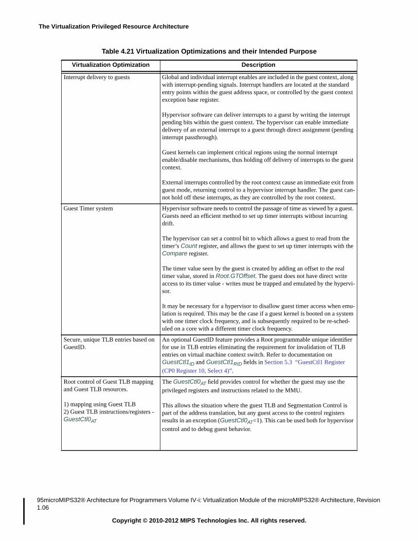
The Virtualization Privileged Resource Architecture
95microMIPS32® Architecture for Programmers Volume IV-i: Virtualization Module of the microMIPS32® Architecture, Revision1.06
Copyright © 2010-2012 MIPS Technologies Inc. All rights reserved.
Interrupt delivery to guests Global and individual interrupt enables are included in the guest context, alongwith interrupt-pending signals. Interrupt handlers are located at the standardentry points within the guest address space, or controlled by the guest contextexception base register.
Hypervisor software can deliver interrupts to a guest by writing the interruptpending bits within the guest context. The hypervisor can enable immediatedelivery of an external interrupt to a guest through direct assignment (pendinginterrupt passthrough).
Guest kernels can implement critical regions using the normal interruptenable/disable mechanisms, thus holding off delivery of interrupts to the guestcontext.
External interrupts controlled by the root context cause an immediate exit fromguest mode, returning control to a hypervisor interrupt handler. The guest can-not hold off these interrupts, as they are controlled by the root context.
Guest Timer system Hypervisor software needs to control the passage of time as viewed by a guest.Guests need an efficient method to set up timer interrupts without incurringdrift.
The hypervisor can set a control bit to which allows a guest to read from thetimer’s Count register, and allows the guest to set up timer interrupts with theCompare register.
The timer value seen by the guest is created by adding an offset to the realtimer value, stored in Root.GTOffset. The guest does not have direct writeaccess to its timer value - writes must be trapped and emulated by the hypervi-sor.
It may be necessary for a hypervisor to disallow guest timer access when emu-lation is required. This may be the case if a guest kernel is booted on a systemwith one timer clock frequency, and is subsequently required to be re-sched-uled on a core with a different timer clock frequency.
Secure, unique TLB entries based onGuestID.
An optional GuestID feature provides a Root programmable unique identifierfor use in TLB entries eliminating the requirement for invalidation of TLBentries on virtual machine context switch. Refer to documentation onGuestCtl1ID and GuestCtl1RID fields in Section 5.3 “GuestCtl1 Register
(CP0 Register 10, Select 4)”.
Root control of Guest TLB mappingand Guest TLB resources.
1) mapping using Guest TLB2) Guest TLB instructions/registers -GuestCtl0AT
The GuestCtl0AT field provides control for whether the guest may use the
privileged registers and instructions related to the MMU.
This allows the situation where the guest TLB and Segmentation Control ispart of the address translation, but any guest access to the control registersresults in an exception (GuestCtl0AT=1). This can be used both for hypervisor
control and to debug guest behavior.
Table 4.21 Virtualization Optimizations and their Intended Purpose
Virtualization Optimization Description

4.13 Virtualization Module features and Hypervisor Software
microMIPS32® Architecture for Programmers Volume IV-i: Virtualization Module of the microMIPS32® Architecture, Revision1.06 96
Copyright © 2010-2012 MIPS Technologies Inc. All rights reserved.
Guest Software Field Change excep-tions
The Guest Software Field Change exception system allows for hypervisorintervention before certain guest-context register fields are changed. Theexception is taken prior to execution of the instruction which would have mod-ified the field.
Some guest register fields are implemented which correspond to fields in theroot CP0 context, but are not actually connected to hardware. An example isthe “reduced power” control bit StatusRP. When the guest kernel changes the
value of such a field, it is expecting some change of behavior in the virtualmachine. The field-change exception allows the hypervisor to respond appro-priately.In other cases (e.g., CauseIV) the field change would affect guest execution,
but hypervisor intervention may be required in order to set up some otheraspect of the virtual machine - for the example given, changes may be requiredto how external interrupts are passed to the guest.
Guest Hardware Field Change excep-tion
The Guest Hardware Field Change exception is related to the Guest SoftwareField Change exception. It is used to trigger hypervisor intervention on a hard-ware initiated field change within a guest. This mechanism can be used fordebug, security or emulation purposes by the hypervisor.
Guest Privileged Sensitive Instructionexceptions
The guest kernel mode is a limited privilege mode. The Guest Privileged Sen-sitive Instruction exception is the primary mechanism by which the hypervisortraps privileged instructions executed in guest mode.
It can be used for emulation of non-existent CP0 registers, and emulation ofaccesses to registers which have been disabled by the hypervisor.
The hypervisor is provided with a catch-all mechanism to trap on all guestprivileged operations (GuestCtl0CP0), and a number of more targeted
enables. These targeted enables include fields to control access to guestaddress translation (GuestCtl0AT), the guest timer (GuestCtl0GT), limited
cache operations (GuestCtl0CG), and the Config0-7 registers present in the
guest context (GuestCtl0CF).
The ability to control access to these features allows the hypervisor to restrictguest permissions, or to emulate the hardware behavior expected by a guest -for example different Config0-7 registers than are present in the machine.
Guest Reserved Instruction Redirectexception
A control bit is provided (GuestCtl0RI) which allows guest RI exceptions to
be redirected to hypervisor software. This enables emulation of instructionswhich are not available in the guest context.
New privileged instruction HYP-CALL
A new instruction is provided, specifically to allow guest kernels to make APIcalls to the hypervisor software. This can be used from both guest-kernel androot-kernel modes.
Table 4.21 Virtualization Optimizations and their Intended Purpose
Virtualization Optimization Description

The Virtualization Privileged Resource Architecture
97microMIPS32® Architecture for Programmers Volume IV-i: Virtualization Module of the microMIPS32® Architecture, Revision1.06
Copyright © 2010-2012 MIPS Technologies Inc. All rights reserved.
New privileged instructionsMFGC0, MTGC0TLBGINV, TLBGINVF,TLBGR, TLBGWI,TLBGP, TLBGWR
New instructions are provided to allow access to the guest CP0 context forhypervisor software running in root mode. These instructions also provideaccess to the guest CP0 context for instructions executed in Debug mode, pro-vided by the EJTAG debug system.
The instructions MFGC0 and MTGC0 allow data to be transferred betweengeneral purpose registers (GPRs) and guest CP0 context registers.
The instructions TLBGINV, TLBGINVF, TLBGP, TLBGR, TLBGWI andTLBGWR are used from root mode to access the guest context TLB using theTLB registers located in the guest context.
Table 4.21 Virtualization Optimizations and their Intended Purpose
Virtualization Optimization Description

4.14 Lightweight Virtualization
microMIPS32® Architecture for Programmers Volume IV-i: Virtualization Module of the microMIPS32® Architecture, Revision1.06 98
Copyright © 2010-2012 MIPS Technologies Inc. All rights reserved.
4.14 Lightweight Virtualization
4.14.1 Introduction
The Virtualization architecture provides support for a lightweight implementation. The focus of such an implementa-tion is to reduce implementation cost and feature complexity. The added benefit of reduced feature complexity is thatroot software is simplified to the point where it need not be a complete hypervisor. For example, it may handle guestinterrupts, guest exceptions and related context switching, but it wouldn’t provide support for an added level of guesttranslation.
The lightweight virtualization specification may also support a different class of embedded applications. For exam-ple, where a Root Protection Unit (RPU) is used, the guests are not different OSes, but applications within an OS,where the applications are from different vendors who do not trust each other. Virtualization in this case has beenextended to secure embedded applications.
4.14.2 Support for Lightweight Virtualization
4.14.2.1 Root Protection Unit (RPU)
The RPU is a defeatured Root TLB that does not translate a guest physical address to a root physical address, and thusdoes not require storage for root physical address. Instead it assumes that the guest physical address is identitymapped to physical memory. However, the RPU checks the guest physical address on a page basis, where the page isprogrammed by root software. If the page matches, then the guest has access to related physical memory. Otherwisethe access will trap to root software, using standard exceptions.
The RPU and its software interface support all instructions and COP0 registers of the baseline architecture and exten-sions provided in the Virtualization Module. Root EntryLo0 and EntryLo1 PFN fields are assumed read-only as 0since the RPU does not translate guest physical addresses.
The CCA(Cache Coherency Attribute) field is required if guest CCA nesting is implemented. Nested guest CCA han-dling is described in Section 4.5.3 . Otherwise the guest CCA field is not required.
The RPU supports XI(Execute-Inhibit), RI(Read-Inhibit) along with D(Dirty) page attributes which are mandatory inan RPU implementation.
An RPU will support multiple page-sizes, though it is implementation dependent in the baseline architecture as towhich page sizes are supported.
The RPU is only supported in a configuration with a root FMT (Fixed Mapping Table). Any addresses in root modemust use the Root FMT. Any guest addresses go through the guest FMT or TLB, and RPU.
An RPU is present in an implementation that supports virtualization (Root.Config3VZ=1) and has a root FMT(Root.ConfigMT=3). It is thus possible for the guest MMU to support a guest TLB with an RPU.
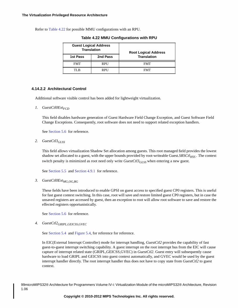
The Virtualization Privileged Resource Architecture
99microMIPS32® Architecture for Programmers Volume IV-i: Virtualization Module of the microMIPS32® Architecture, Revision1.06
Copyright © 2010-2012 MIPS Technologies Inc. All rights reserved.
Refer to Table 4.22 for possible MMU configurations with an RPU.
4.14.2.2 Architectural Control
Additional software visible control has been added for lightweight virtualization.
1. GuestCtl0ExtFCD
This field disables hardware generation of Guest Hardware Field Change Exception, and Guest Software FieldChange Exceptions. Consequently, root software does not need to support related exception handlers.
See Section 5.6 for reference.
2. GuestCtl3GLSS
This field allows virtualization Shadow Set allocation among guests. This root managed field provides the lowestshadow set allocated to a guest, with the upper bounds provided by root-writeable Guest.SRSCtlHSS . The contextswitch penalty is minimized as root need only write GuestCtl3GLSS when entering a new guest.
See Section 5.5 and Section 4.9.1 for reference.
3. GuestCtl0ExtMG,OG,BG
These fields have been introduced to enable GPSI on guest access to specified guest CP0 registers. This is usefulfor fast guest context switching. In this case, root will save and restore limited guest CP0 registers, but in case theunsaved registers are accessed by guest, then an exception to root will allow root software to save and restore theeffected registers opportunistically.
See Section 5.6 for reference.
4. GuestCtl2GRIPL,GEICSS,GVEC
See Section 5.4 and Figure 5.4, for reference for reference.
In EIC(External Interrupt Controller) mode for interrupt handling, GuestCtl2 provides the capability of fastguest-to-guest interrupt switching capability. A guest interrupt on the root interrupt bus from the EIC will causecapture of interrupt related state (GRIPL,GEICSS,GVEC) in GuestCtl2. Guest entry will subsequently causehardware to load GRIPL and GEICSS into guest context automatically, and GVEC would be used by the guestinterrupt handler directly. The root interrupt handler thus does not have to copy state from GuestCtl2 to guestcontext.
Table 4.22 MMU Configurations with RPU
Guest Logical AddressTranslation
Root Logical AddressTranslation1st Pass 2nd Pass
FMT RPU FMT
TLB RPU FMT

4.14 Lightweight Virtualization
microMIPS32® Architecture for Programmers Volume IV-i: Virtualization Module of the microMIPS32® Architecture, Revision1.06 100
Copyright © 2010-2012 MIPS Technologies Inc. All rights reserved.
See Section 4.8.1.2 for a description of EIC handling.
4.14.2.3 Optional Features of Virtualization Architecture
Certain features are optional in the virtualization architecture. An implementation may choose to support such fea-tures based on the class of applications that the product will support. An example being that an implementation neednot support root write of all Configuration fields listed in Table 4.12.

The Virtualization Privileged Resource Architecture
101 microMIPS32® Architecture for Programmers Volume IV-i: Virtualization Module of the microMIPS32® Architecture, Revi-sion 1.06
Copyright © 2010-2012 MIPS Technologies Inc. All rights reserved.

Chapter 5
microMIPS32® Architecture for Programmers Volume IV-i: Virtualization Module of the microMIPS32® Architecture, Revision1.06 102
Copyright © 2010-2012 MIPS Technologies Inc. All rights reserved.
Coprocessor 0 (CP0) Registers
The Coprocessor 0 (CP0) registers provide the interface between the Instruction Set Architecture (ISA) and the Privi-leged Resource Architecture (PRA). The CP0 registers that are added or extended by the Virtualization Module arediscussed below, with the registers presented in numerical order, first by register number, then by select field number.
5.1 CP0 Register Summary
Table 5.1 lists the CP0 registers affected by the Virtualization Module specification, in numerical order. The individ-ual registers are described later in this document. Registers which are not described here follow the definitions fromthe microMIPS32 Privileged Resource Architecture. The Sel column indicates the value to be used in the field of thesame name in the MFC0 and MTC0 instructions.
Section 4.6.3 “Guest CP0 registers” describes CP0 register availability in guest mode.
Table 5.1 Virtualization Module Changes to Coprocessor 0 Registers in Numerical Order
RegisterNumber Sel
RegisterName Modification Reference
ComplianceLevel
12 6 GuestCtl0 New Register. Controls guest mode behavior. Section 5.2 Required
10 4 GuestCtl1 New Register. Guest ID Section 5.3 Optional
10 5 GuestCtl2 New Register. Interrupt related Section 5.4 Optional
10 6 GuestCtl3 New Register. GPR Shadow Set related. Section 5.5 Optional
11 4 GuestCtl0Ext Extension to GuestCtl0 Section 5.6 Optional
12 7 GTOffset New Register. Guest timer offset. Section 5.7 Required
13 0 Cause Addition of hypervisor cause code. Section 5.8 Required
16 3 Config3 Identifies Virtualization Module feature set. Section 5.9 Required
19 0 WatchHi Watch Debug. Section 5.10 Optional
25 0 PerfCnt Performance Counter, adds virtualization support. Section 5.11 Optional
8 0 BadVaddr Upper 32-bits of BadVaddr for XPA (ExtendedPhysical Address).MT(F)H(G)C0 must be used for access.
Section 5.12 Optional
10 0 EntryHi Upper 32-bits of EntryHi for XPA (ExtendedPhysical Address).MT(F)H(G)C0 must be used for access.
Section 5.13 Optional
31 2 KScratch1 Required in root context. - Required
31 3 KScratch2 Required in root context. - Required

Coprocessor 0 (CP0) Registers
103 microMIPS32® Architecture for Programmers Volume IV-i: Virtualization Module of the microMIPS32® Architecture, Revi-sion 1.06
Copyright © 2010-2012 MIPS Technologies Inc. All rights reserved.
5.2 GuestCtl0 Register (CP0 Register 12, Select 6)
Compliance Level: Required by the Virtualization Module.
The GuestCtl0 register contains control bits that indicate whether the base mode of the processor is guest mode orroot mode, plus additional bits controlling guest mode access to privileged resources. The GuestCtl0 register is acces-sible only in root mode.
The GuestCtl0 register is instantiated per-VPE in a MT Module processor. This register is added by the VirtualizationModule.
Note on behaviour of GuestCtl0DRG/RAD: These R/W fields define additional functions for the Guest and Root TLBs.Both must be interpreted together. An implementation does not have to support all valid combinations. Root softwarecan test supported combinations by writing then reading legal values. Legal values for (RAD,DRG)={00,01,11}.
Figure 5.1 shows the format of the Virtualization Module GuestCtl0 register; Table 5.2 describes the GuestCtl0 regis-ter fields.
Figure 5.1 GuestCtl0 Register Format31 30 29 28 27 26 25 24 23 22 21 20 19 18 17 16 15 14 13 12 11 10 9 8 7 6 5 4 3 2 1 0
GM RI MC CP0 AT GT CG CF G1 ImplG
0E PT ASE PIP
RA
D
DR
G
G2 GExcCode
S FC2
S FC1

5.2 GuestCtl0 Register (CP0 Register 12, Select 6)
microMIPS32® Architecture for Programmers Volume IV-i: Virtualization Module of the microMIPS32® Architecture, Revision1.06 104
Copyright © 2010-2012 MIPS Technologies Inc. All rights reserved.
Table 5.2 GuestCtl0 Register Field Descriptions
Fields
DescriptionRead /Write
ResetState ComplianceName Bits
GM 31 Guest ModeThe processor is in guest mode when GM=1, Root.StatusEXL=0 and
Root.StatusERL=0 and Root.DebugDM=0.
R/W 0 Required
RI 30 Guest Reserved Instruction Redirect. R/W 0 Required
MC 29 Guest Mode-Change exception enable. The purpose of this enable is toprovide Root software control over certain mode-changing eventswithin guest context that may be frequent in guest context by causingField Change exceptions.
R/W 0 Required
Encoding Meaning
0 Reserved Instruction exceptions dur-ing guest-mode execution are taken inguest mode.
1 Reserved Instruction exceptions dur-ing guest-mode execution result in aGuest Reserved Instruction Redirectexception, taken in root mode.
Encoding Meaning
0 During guest mode execution a hardwareinitiated change to Guest.StatusEXL will
not trigger a Guest Hardware FieldChange Exception.During guest mode execution, a softwareinitiated change to Guest.StatusUM/KSUwill not trigger a Guest Software FieldChange Exception.
1 During guest mode execution a hardwareinitiated change to Guest.StatusEXL will
trigger a Guest Hardware Field ChangeException.During guest mode execution, a softwareinitiated change to Guest.StatusUM/KSU
will trigger a Guest Software FieldChange Exception.

Coprocessor 0 (CP0) Registers
105 microMIPS32® Architecture for Programmers Volume IV-i: Virtualization Module of the microMIPS32® Architecture, Revi-sion 1.06
Copyright © 2010-2012 MIPS Technologies Inc. All rights reserved.
CP0 28 Guest access to coprocessor 0.
The list of Guest Privileged Sensitive instructions which trigger aGuest Privileged Sensitive Instruction exception is given in Section4.7.7The CP0 bit has no other effect on the operation of coprocessor 0 inguest mode.
R/W 0 Required
Table 5.2 GuestCtl0 Register Field Descriptions
Fields
DescriptionRead /Write
ResetState ComplianceName Bits
Encoding Meaning
0 Guest-kernel use of any Guest Privi-leged Sensitive Instruction will triggera Guest Privileged Sensitive Instruc-tion exception.E.g., Guest use of TLBWI alwayscauses GPSI if CP0=0.
1 Guest-kernel use of selective GuestPrivileged Sensitive Instructions ispermitted, subject to all other excep-tion conditions.Eg., Guest use of TLBWI only causesGPSI if GuestCtl0AT !=3 while CP0=1

5.2 GuestCtl0 Register (CP0 Register 12, Select 6)
microMIPS32® Architecture for Programmers Volume IV-i: Virtualization Module of the microMIPS32® Architecture, Revision1.06 106
Copyright © 2010-2012 MIPS Technologies Inc. All rights reserved.
AT 27:26 Guest Address Translation control.
Guest TLB resources are:• TLB related Instructions - TLBWR, TLBWI, TLBR, TLBP, TLB-
INV, TLBINVF.• Supporting Registers - Index, Random, EntryLo0, EntryLo1,
EntryHi, Context, XContext, ContextConfig, PageMask,PageGrain, SegCtl0, SegCtl1, SegCtl2, PWBase, PWField,PWSize, PWCtl.
If the Guest TLB resources (excluding Index, Random, EntryLo0,EntryLo1, Context, XContext, ContextConfig, PageMask andEntryHi) are under Root control (GuestCtl0AT=1), Guest use of these
instructions or access to any of these registers (see Table 4.8), willtrigger a Guest Privileged Sensitive Instruction exception, allowingRoot to control Guest address translation directly. For additional infor-mation refer to Table 4.21, Entry: “Root control of Guest TLB map-ping and Guest TLB resources.”
In default mode (GuestCtl0AT=3), the Guest TLB resources are active
under Guest control. Refer to Section 4.5 “Virtual Memory” for addi-tional information on guest virtual address translation.
R or R/Wif more
thandefaultmodeimple-
mented.
Imple-mentation
defined
Required
Table 5.2 GuestCtl0 Register Field Descriptions
Fields
DescriptionRead /Write
ResetState ComplianceName Bits
Encoding Meaning
0 Reserved.
1 Guest MMU under Root control.
Guest and Root MMU both implemented andactive in hardware.This mode is optional.
2 Reserved
3 Guest MMU under Guest control.
Guest and Root MMU both implemented andactive in hardware.This mode is required.

Coprocessor 0 (CP0) Registers
107 microMIPS32® Architecture for Programmers Volume IV-i: Virtualization Module of the microMIPS32® Architecture, Revi-sion 1.06
Copyright © 2010-2012 MIPS Technologies Inc. All rights reserved.
GT 25 Timer register access.
The GT bit has no other effect on the operation of timers in guestmode.
R/W 0 Required
CG 24 Cache Instruction Guest-mode enable.If R0, then GPSI exception will always occur. CG as an enable in thuisthus optional.
CACHEE is optional in the baseline architecture.
R0,R/W
0 Optional
CF 23 Config register access.
The CF bit has no other effect on the operation of Config registerfields in guest mode.
R/W 0 Required
Table 5.2 GuestCtl0 Register Field Descriptions
Fields
DescriptionRead /Write
ResetState ComplianceName Bits
Encoding Meaning
0 Guest-kernel access to Count orCompare registers, or a read fromCC with RDHWR will trigger a GuestPrivileged Sensitive Instructionexception.
1 Guest kernel read access from Countand guest-kernel read or write accessto Compare is permitted. Guest readsfrom CC using RDHWR are permit-ted in any mode.
Encoding Meaning
0 A Guest Privileged Sensitive Instruc-tion exception will result from use theCACHE, CACHEE instruction.
1 The CACHE, CACHEE instructioncan be used with an Effective AddressOperand type of ‘Address’. A GuestPrivileged Sensitive Instructionexception will result from use of anyother Effective Address Operand type.
Encoding Meaning
0 Guest-kernel write access toConfig0-7 will trigger a Guest Privi-leged Sensitive Instruction exception.
1 Guest-kernel access to Config0-7 ispermitted.

5.2 GuestCtl0 Register (CP0 Register 12, Select 6)
microMIPS32® Architecture for Programmers Volume IV-i: Virtualization Module of the microMIPS32® Architecture, Revision1.06 108
Copyright © 2010-2012 MIPS Technologies Inc. All rights reserved.
G1 22 GuestCtl1 register implemented. Set by hardware. R preset Required
Impl 21..20 Implementation defined.These bits are implementation dependent and notdefined by the architecture. If not implemented,they must be ignored on write and read as zero.If implemented and if modifying the behavior ofthe processor, it must be defined in such a way thatcorrect behavior is preserved if software, with no knowledgeof these bits, reads the GuestCtl0 register, modifiesanother field, and writes the updated value back to theGuestCtl0 register.
R/W 0 Required
G0E 19 GuestCtl0Ext register implemented. Set by hardware. R preset Required
PT 18 Defines the existence of the Pending Interrupt Passthrough feature.
Implementation of the Pending Interrupt Passthrough feature isstrongly recommended.
R preset Required
ASE 17..16 Reserved for MCU Module Pending Interrupt Passthrough. 0 0 Required forMCU Module;
OtherwiseReserved
Table 5.2 GuestCtl0 Register Field Descriptions
Fields
DescriptionRead /Write
ResetState ComplianceName Bits
Encoding Meaning
0 Unimplemented
1 Implemented.
Encoding Meaning
0 Unimplemented
1 Implemented.
Encoding Meaning
0 GuestCtl0PIP not supported.
GuestCtl0PIP is a reserved field.
All external interrupts are processedvia Root intervention.
1 GuestCtl0PIP supported. Interrupts
may be assigned to Root or Guest.
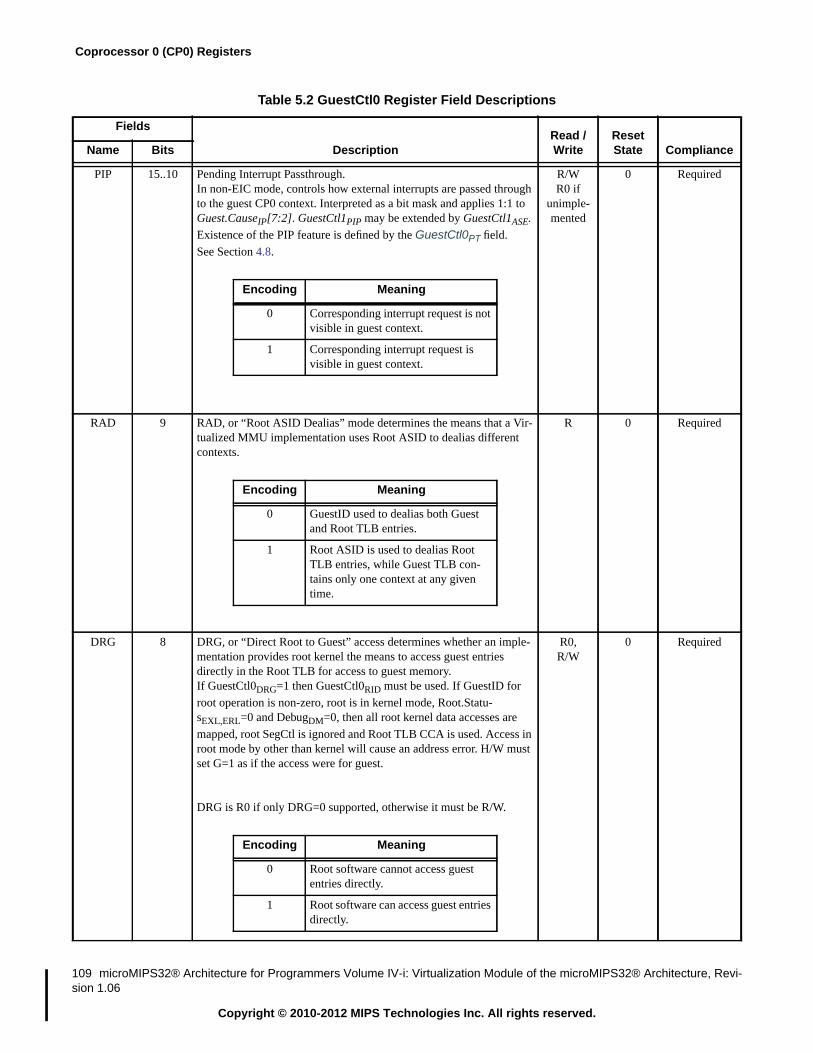
Coprocessor 0 (CP0) Registers
109 microMIPS32® Architecture for Programmers Volume IV-i: Virtualization Module of the microMIPS32® Architecture, Revi-sion 1.06
Copyright © 2010-2012 MIPS Technologies Inc. All rights reserved.
PIP 15..10 Pending Interrupt Passthrough.In non-EIC mode, controls how external interrupts are passed throughto the guest CP0 context. Interpreted as a bit mask and applies 1:1 toGuest.CauseIP[7:2]. GuestCtl1PIP may be extended by GuestCtl1ASE.
Existence of the PIP feature is defined by the GuestCtl0PT field.
See Section 4.8.
R/WR0 if
unimple-mented
0 Required
RAD 9 RAD, or “Root ASID Dealias” mode determines the means that a Vir-tualized MMU implementation uses Root ASID to dealias differentcontexts.
R 0 Required
DRG 8 DRG, or “Direct Root to Guest” access determines whether an imple-mentation provides root kernel the means to access guest entriesdirectly in the Root TLB for access to guest memory.If GuestCtl0DRG=1 then GuestCtl0RID must be used. If GuestID for
root operation is non-zero, root is in kernel mode, Root.Statu-sEXL,ERL=0 and DebugDM=0, then all root kernel data accesses are
mapped, root SegCtl is ignored and Root TLB CCA is used. Access inroot mode by other than kernel will cause an address error. H/W mustset G=1 as if the access were for guest.
DRG is R0 if only DRG=0 supported, otherwise it must be R/W.
R0,R/W
0 Required
Table 5.2 GuestCtl0 Register Field Descriptions
Fields
DescriptionRead /Write
ResetState ComplianceName Bits
Encoding Meaning
0 Corresponding interrupt request is notvisible in guest context.
1 Corresponding interrupt request isvisible in guest context.
Encoding Meaning
0 GuestID used to dealias both Guestand Root TLB entries.
1 Root ASID is used to dealias RootTLB entries, while Guest TLB con-tains only one context at any giventime.
Encoding Meaning
0 Root software cannot access guestentries directly.
1 Root software can access guest entriesdirectly.

5.2 GuestCtl0 Register (CP0 Register 12, Select 6)
microMIPS32® Architecture for Programmers Volume IV-i: Virtualization Module of the microMIPS32® Architecture, Revision1.06 110
Copyright © 2010-2012 MIPS Technologies Inc. All rights reserved.
Table 5.3 describes the cause codes use for GExcCode.
G2 7 GuestCtl2 register implemented. Set by hardware. R preset Required
GExc-Code
6..2 Hypervisor exception cause code. Described in Table 5.3.This field is UNDEFINED on a root exception.
R Undefined Required
SFC2 1 Guest Software Field Change exception enable for Guest.StatusCU[2].
The purpose of this enable is to provide Root software control overguest COP2 enable related Field Change exception. Guest softwaremay utilize StatusCU2 for COP2 specific context switching.
R/W ifimple-
mented, 0otherwise
0 Optional
SFC1 0 Guest Software Field Change exception enable for Guest.StatusCU[1].
The purpose of this enable is to provide Root software control overguest COP1 enable related Field Change exception. Guest softwaremay utilize StatusCU1 for COP1 specific context switching.
R/W ifimple-
mented, 0otherwise.
0 Optional
Table 5.3 GuestCtl0 GExcCode values
Exception code value
Mnemonic DescriptionDecimal Hexadecimal
0 0x00 GPSI Guest Privileged Sensitive instruction. Taken when execution of a Guest Privi-leged Sensitive Instruction was attempted from guest-kernel mode, but theinstruction was not enabled for guest-kernel mode.
1 0x01 GSFC Guest Software Field Change event
2 0x02 HC Hypercall
Table 5.2 GuestCtl0 Register Field Descriptions
Fields
DescriptionRead /Write
ResetState ComplianceName Bits
Encoding Meaning
0 Unimplemented
1 Implemented.
Encoding Meaning
0 GSFC exception taken if CU[2] ismodified by guest.
1 GSFC exception not taken if CU[2]modified by guest.
Encoding Meaning
0 GSFC exception taken if CU[1] ismodified by guest.
1 GSFC exception not taken if CU[1]modified by guest.

Coprocessor 0 (CP0) Registers
111 microMIPS32® Architecture for Programmers Volume IV-i: Virtualization Module of the microMIPS32® Architecture, Revi-sion 1.06
Copyright © 2010-2012 MIPS Technologies Inc. All rights reserved.
5.3 GuestCtl1 Register (CP0 Register 10, Select 4)
Compliance Level: Optional in the Virtualization Module.
The GuestCtl1 register defines GuestID control fields for Root (GuestCtl1RID) and Guest (GuestCtl1ID) which may beused in the context of TLB instructions, instruction and data address translation. The GuestCtl1RID field additionallyis written by the processor on a TLBR or TLBGR instruction in Root mode, then containing the GuestID read fromthe TLB entry. A TLBR executed in Guest mode does not cause a write to either GuestCtl1ID and GuestCtl1RID.
GuestCtl1 is optional and thus the use of GuestID is optional in the context of TLB instructions, instruction and dataaddress translation. The GuestCtl1 register only exists in Root Context. GuestID value of 0 is reserved for Root.
Section 4.5.1 “Virtualized MMU GuestID Use” provides additional detail on GuestID usage as it applies to instruc-tion and data address translation. Section 4.6.2 “New CP0 Instructions” describes the TLB instructions and their useof GuestID.
The primary purpose of the GuestID is to provide a unique component of the Guest/Root TLB entry eliminating TLBinvalidation overhead on virtual machine level context switch.
A system implementing a GuestID is required to support a guest identifier field (GID) in each Guest and Root TLBentry. This GuestID field within the TLB is not accessible to the Guest. While operating in guest context, the behaviorof guest TLB operations is constrained by the GuestCtl1ID field so that only guest TLB entries with a matching GIDfield are considered.
The actual number of bits usable in the GuestCtl1ID and GuestCtl1RID fields is implementation dependent. Softwaremay determine the usable size of these fields by writing all ones and reading the value back. The size of GuestCtl1ID
and GuestCtl1RID must be equal.
The GuestCtl1 register is instantiated per-VPE in a MT Module processor.
3 0x03 GRR Guest Reserved Instruction Redirect. A Reserved Instruction exception wouldbe taken in guest mode. When GuestCtl0RI=1, this root-mode exception is
raised before the guest-mode exception can be taken.
4 - 7 0x4 - 0x7 IMP Available for implementation specific use
8 0x08 GVA Guest mode initiated Root TLB exception has Guest Virtual Address available.Set when a Guest mode initiated TLB translation results in a Root TLB relatedexception occurring in Root mode and the Guest Physical Address is not avail-able.
9 0x09 GHFC Guest Hardware Field Change event
10 0x0A GPA Guest mode initiated Root TLB exception has Guest Physical Address avail-able.Set when a Guest mode initiated TLB translation results in a Root TLB relatedexception occurring in Root mode and the Guest Physical Address is available.
11 - 31 0xB - 0x1f - Reserved
Table 5.3 GuestCtl0 GExcCode values
Exception code value
Mnemonic DescriptionDecimal Hexadecimal

5.4 GuestCtl2 Register (CP0 Register 10, Select 5)
microMIPS32® Architecture for Programmers Volume IV-i: Virtualization Module of the microMIPS32® Architecture, Revision1.06 112
Copyright © 2010-2012 MIPS Technologies Inc. All rights reserved.
Figure 5.2 shows the format of the Virtualization Module GuestCtl1 register; Table 5.4 describes the GuestCtl1 regis-ter fields.
Figure 5.2 GuestCtl1 Register Format
5.4 GuestCtl2 Register (CP0 Register 10, Select 5)
Compliance Level: Optional in the Virtualization Module.
The GuestCtl2 register is optional in an implementation. It is only required if support for Virtual Interrupts innon-EIC mode is included in an implementation. Alternatively, if EIC mode is supported, then GuestCtl2 is required.Refer to Section 4.8.1 “External Interrupts” for a description of interrupt handling in EIC and non-EIC modes.
An implementation that supports the virtual interrupt functionality of GuestCtl2 is not required to support root writesof Guest.CauseIP[7:2] or Guest.CauseRIPL as described in Table 4.12.
GuestCtl2 is present in an implementation if GuestCtl2G2=1.
The GuestCtl2 register is instantiated per-VPE in a MT Module processor.
Figure 5.3 shows the format of the Virtualization Module GuestCtl2 register in non-EIC mode. Table 5.5 describesthe non-EIC mode GuestCtl2 register fields.
Figure 5.4 shows the format of the Virtualization Module GuestCtl2 register in EIC mode. Table 5.6 describes theEIC mode GuestCtl2 register fields.
Figure 5.3 GuestCtl2 Register Format for non-EIC mode
31 30 29 28 27 26 25 24 23 22 21 20 19 18 17 16 15 14 13 12 11 10 9 8 7 6 5 4 3 2 1 0
EID RID 0 ID
Table 5.4 GuestCtl1 Register Field Descriptions
Fields
DescriptionRead /Write
ResetState ComplianceName Bits
EID 31..24 External Interrupt Controller Guest ID.Required if an External Interrupt Controller (EIC) is supported.A guest interrupt which is posted by the EIC to the root interrupt bus,must cause the Guest ID of the root interrupt bus to be registered in EIDonce the interrupt is taken.If implemented, the field is read-only and set by hardware.If not implemented then must be written as zero; returns zero on read.
R0 or R 0 Optional
RID 23..16 Root control GuestID. Used by root TLB operations, and whenGuestCtl0DRG=1 in root mode.
R/W 0 Required
0 15..8 Must be written as zero; returns zero on read. R0 0 Reserved
ID 7..0 Guest control GuestID. Identifies resident guest. Applies to guestaddress translation.
R/W 0 Required
31 30 29 28 27 26 25 24 23 22 21 20 19 18 17 16 15 14 13 12 11 10 9 8 7 6 5 4 3 2 1 0
ASE HC 0 ASE VIP 0 Impl

Coprocessor 0 (CP0) Registers
113 microMIPS32® Architecture for Programmers Volume IV-i: Virtualization Module of the microMIPS32® Architecture, Revi-sion 1.06
Copyright © 2010-2012 MIPS Technologies Inc. All rights reserved.
Figure 5.4 GuestCtl2 Register Format for EIC mode31 30 29 28 27 26 25 24 23 22 21 20 19 18 17 16 15 14 13 12 11 10 9 8 7 6 5 4 3 2 1 0
ASE GRIPL 0 GEICSS 0 GVEC
Table 5.5 non-EIC mode GuestCtl2 Register Field Descriptions
Fields
DescriptionRead /Write
ResetState ComplianceName Bits
ASE 31:30 MCU Module extension for HC. Must be written as zero; returns zeroon read.
R0 0 Reserved
HC 29..24 Hardware Clear for GuestCtl2VIP
This set of bits maps one to one to GuestCtl2VIP.
HC may be bit-wise Read-only or R/W. If a bit is Read-only, then it maybe preset to 0 or 1. Similarly, if a bit is R/W, then it may be reset to 0 or1. The interpretation of 0 or 1 state follows.
In the case of HC=0, Guest.CauseIP[n+2] could continue to be asserted
due to an external interrupt when GuestCtl2VIP[n] is cleared by soft-
ware. Source of external interrupt must be serviced appropriately.
The choice of Read-only vs. R/W is implementation dependent. Rootsoftware can write then read field to determine supported configuration.
R,R/W
0 or 1 Optional
0 25..18 Must be written as zero; returns zero on read. R0 0 Reserved
ASE 17:16 MCU Module extension for VIP. Must be written as zero; returns zeroon read.
R0 0 Reserved
Encoding Meaning
0 The deassertion of related externalinterrupt (IRQ[n]) has no effect onGuestCtl2VIP[n]. Root software must
write zero to GuestCtl2VIP[n] to clear
the virtual interrupt.
1 The deassertion of related externalinterrupt (IRQ[n]) causesGuestCtl2VIP[n] to be cleared by h/w.

5.4 GuestCtl2 Register (CP0 Register 10, Select 5)
microMIPS32® Architecture for Programmers Volume IV-i: Virtualization Module of the microMIPS32® Architecture, Revision1.06 114
Copyright © 2010-2012 MIPS Technologies Inc. All rights reserved.
VIP 15..10 Virtual Interrupt Pending.The VIP field is used by root to inject virtual interrupts into Guest con-text. VIP[5..0] maps to Guest.StatusIP[7..2]. VIP effects Guest.StatusIP
in the the following manner:
R/W 0 Required
0 9..5 Must be written as zero; returns zero on read. R0 0 Reserved
Impl 4:0 Implementation.These bits are implementation dependent and notdefined by the architecture. If not implemented,they must be written as 0, and read as zero.If implemented and if modifying the behavior ofthe processor, it must be defined in such a way thatcorrect behavior is preserved if software, with no knowledgeof these bits, reads the GuestCtl2 register, modifiesanother field, and writes the updated value back to theGuestCtl2 register.
R/W 0 Required
Table 5.5 non-EIC mode GuestCtl2 Register Field Descriptions
Fields
DescriptionRead /Write
ResetState ComplianceName Bits
Encoding Meaning
0 Guest.StatusIP[n+2] cannot be
asserted due to VIP[n], though it maybe asserted by an external interruptIRQ[n]. n = 5..0
1 Guest.StatusIP[n+2] must at least be
asserted due to VIP[n]. It may also beasserted by a concurrent externalinterrupt. n=5..0

Coprocessor 0 (CP0) Registers
115 microMIPS32® Architecture for Programmers Volume IV-i: Virtualization Module of the microMIPS32® Architecture, Revi-sion 1.06
Copyright © 2010-2012 MIPS Technologies Inc. All rights reserved.
5.5 GuestCtl3 Register (CP0 Register 10, Select 6)
Compliance Level: Optional in the Virtualization Module.
The GuestCtl3 register is optional. It is required only if Shadow GPR Sets are supported, and the Shadow Sets usedby a guest are virtual and require mapping to physical Shadow Sets. With this mechanism, a pool of Shadow Sets canbe physically shared by partitioning the sets among multiple guests and root, under root control.
Virtual mapping of Guest GPR set(s) is supported if Guest SRSCtlHSS is writeable by root. Presence of GuestCtl3 canbe detected by root software by writing any non-zero value less than or equal to root SRSCtlHSS to Guest SRSCtlHSS.
If a read returns the value written, then GuestCtl3 is present.
Table 5.6 EIC mode GuestCtl2 Register Field Descriptions
Fields
DescriptionRead /Write
ResetState ComplianceName Bits
ASE 31:30 MCU Module extension for GRIPL. Must be written as zero; returnszero on read.
R0 0 Reserved
GRIPL 29..24 Guest RIPLThis field is written only when an interrupt received on the root interruptbus for a guest is taken. The RIPL(Requested Interrupt Priority Level)sent by EIC on the root interrupt bus is written to this field.
Root software can write the field if it needs to modify the EIC valuebefore assigning to guest. It may also clear this field to prevent a transi-tion to guest mode from causing an interrupt if this field was set with anon-zero value earlier.
GRIPL is 10 bits only for an implementation that complies with theMCU Module, otherwise it is 8 bits as in baseline architecture.
R/W 0 Required
GEICSS 21:18 Guest EICSSThis field is written only when an interrupt received on the root interruptbus for a guest is taken. The EICSS (External Interrupt ControllerShadow Set) sent by EIC on the root interrupt bus is written to this field
Root software can write the field if it needs to modify the EIC valuebefore assigning to guest.
R/W Undefined Required
0 17:16 Must be written as zero; returns zero on read. R0 0 Reserved
GVEC 15:0 Guest VectorThis field is written only when an interrupt is received on the root inter-rupt bus for a guest. The Vector Offset (or Number) sent by EIC on theroot interrupt bus is written to this field.
GVEC is not loaded into any guest CP0 field, but is used to generate aninterrupt vector in guest mode using the root interrupt bus vector and notthe guest interrupt bus vector. This will only occur if the interrupt wasfirst taken in root mode.
It is recommended that root software use write access only to restorecontext, not to modify the value delivered by the EIC.
R/W Undefined Required

5.6 GuestCtl0Ext Register (CP0 Register 11, Select 4)
microMIPS32® Architecture for Programmers Volume IV-i: Virtualization Module of the microMIPS32® Architecture, Revision1.06 116
Copyright © 2010-2012 MIPS Technologies Inc. All rights reserved.
The GuestCtl3 register is instantiated per-VPE in a MT Module processor.
Figure 5.3 shows the format of the Virtualization Module GuestCtl3 register; Table 5.7 describes the GuestCtl3 regis-ter fields.
Figure 5.5 GuestCtl3 Register Format
5.6 GuestCtl0Ext Register (CP0 Register 11, Select 4)
Compliance Level: Optional in the Virtualization Module.
GuestCtl0Ext is an optional extension to GuestCtl0. If not supported, the register must read as 0.
GuestCtl0G0E should be read by software to determine if GuestCtl0Ext is implemented.
The GuestCtl0Ext register is instantiated per-VPE in a MT Module processor.
Figure 5.6 shows the format of the Virtualization Module GuestCtl0Ext register; Table 5.8describes the GuestCtl0Extregister fields.
Figure 5.6 GuestCtl0Ext Register Format
31 30 29 28 27 26 25 24 23 22 21 20 19 18 17 16 15 14 13 12 11 10 9 8 7 6 5 4 3 2 1 0
0 0 0 0 0 0 0 GLSS
Table 5.7 GuestCtl3 Register Field Descriptions
Fields
DescriptionRead /Write
ResetState ComplianceName Bits
0 31:4 This bit must be written as zero, returns zero on read. R0 0 Reserved
GLSS 3:0 Guest Lowest Shadow Set number.This determines the lowest physical Shadow Set number assigned byroot to guest. Guest is thus assigned physical Shadow Sets GLSS toGLSS plus Guest SRSCtlHSS.
If this field is reserved, then all writes must be zero, and reads shouldreturn 0.
R0,R/W
0 Required
31 30 29 28 27 26 25 24 23 22 21 20 19 18 17 16 15 14 13 12 11 10 9 8 7 6 5 4 3 2 1 0
0 RPW NCC 0
CG
I
FCD
OG
BG
MG

Coprocessor 0 (CP0) Registers
117 microMIPS32® Architecture for Programmers Volume IV-i: Virtualization Module of the microMIPS32® Architecture, Revi-sion 1.06
Copyright © 2010-2012 MIPS Technologies Inc. All rights reserved.
Table 5.8 GuestCtl0Ext Register Field Descriptions
Fields
DescriptionRead /Write
ResetState ComplianceName Bits
0 31:6 Must be written as zero, returns zero on read. R0 0 Reserved
RPW 9:8 Root Page Walk configuration.Determines whether Root COP0 Page Walk registers are used for GPAto RPA or RVA to RPA translations, or both.Support for RPW is optional. If this field is read-only 0, it implies page-walk is supported for both cases.
R0,R/W
0 Optional
NCC 7:6 Nested Cache Coherency AttributesDetermines whether guest CCA is modified by root CCA in 2nd step ofguest address translation.
R Preset Optional
0 5 Must be written as zero, returns zero on read. R0 0 Reserved
Encoding Meaning
00 Pagewalk, if enabled, is enabled forboth. Root software is responsible forrestoring COP0 Page Walk relatedregisters on context switch betweenroot and guest.
01 Reserved
10 Pagewalk in root context is enabledfor guest GPA to RPA translation.Root miss in root TLB will cause anexception.
11 Pagewalk in root context is enabledfor root RVA to RPA translation.Guest miss in root TLB will cause aroot exception.
Encoding Meaning
00 Guest CCA is independent of root CCA
01 Guest CCA is modified by root CCA inmanner described in Table 4.4
10 Reserved
11 Reserved

5.6 GuestCtl0Ext Register (CP0 Register 11, Select 4)
microMIPS32® Architecture for Programmers Volume IV-i: Virtualization Module of the microMIPS32® Architecture, Revision1.06 118
Copyright © 2010-2012 MIPS Technologies Inc. All rights reserved.
CGI 4 Related to GuestCtl0CG. Allows execution of CACHE, CACHEE Index
Invalidate operations in guest mode.
This field is R0 if feature is not implemented.The CACHEE instruction is optional in the baseline architecture.
R0,R/W
0 Optional
FCD 3 Disables Guest Software/Hardware Field Change Exceptions(GSFC/GHFC).This mode is useful for an implementation with root software that is nota full-featured hypervisor. For e.g., the software may just support mem-ory protection, but may not require protection of CP0 state.
If FCD=1, then hardware must treat guest write, in case of GSFC, andhardware events, in case of GHFC, as in the baseline architecture.
This field is R0 if feature is not implemented.
R0,R/W
0 Optional
Table 5.8 GuestCtl0Ext Register Field Descriptions
Fields
DescriptionRead /Write
ResetState ComplianceName Bits
Encoding Meaning
0 Definition of GuestCtl0CG does not
change.
1 If GuestCtl0CG =1 and
GuestCtl0ExtCGI =1, then all CACHE,
CACHEE Index Invalidate (code0xb000) operations may execute inguest mode without causing a GPSI.
Encoding Meaning
0 GSFC or GHFC event will causeexception.
1 GSFC or GHFC event will not causeexception.

Coprocessor 0 (CP0) Registers
119 microMIPS32® Architecture for Programmers Volume IV-i: Virtualization Module of the microMIPS32® Architecture, Revi-sion 1.06
Copyright © 2010-2012 MIPS Technologies Inc. All rights reserved.
5.7 GTOffset Register (CP0 Register 12, Select 7)
Compliance Level: Required by the Virtualization Module.
Timekeeping within the guest context is controlled by root mode. The guest time value is generated by adding thetwo’s complement offset in the Root.GTOffset register to the root timer in value Root.Count.
OG 2 Other GPSI Enable. Applies to UserLocal, HWREna, LLAddr, Reserved(for Architecture), UserTraceData1, UserTraceData2, KScratch1through KScratch6, when implemented. If function is not supported, thisfield reads as 0.
For a description of Reserved for Architecture registers, see Section4.6.3.1 .UserTraceData1, UserTraceData2 are optional CP0 registers defined inMIPS PDTrace, iFlowTrace specifications.
This field is R0 if feature is not implemented.
R0,R/W
0 Optional
BG 1 Bad register GPSI Enable. Applies to BadVAddr, BadInstr, BadInstrPwhen implemented. If function is not supported, this field reads as 0.
This field is R0 if feature is not implemented.
R0,R/W
0 Optional
MG 0 MMU GPSI Enable. Applies to Index, Random, EntryLo0, EntryLo1,Context, ContextConfig, PageMask, EntryHi. If function is not sup-ported, this field reads as 0.
This field is R0 if feature is not implemented.
R0,R/W
0 Optional
Table 5.8 GuestCtl0Ext Register Field Descriptions
Fields
DescriptionRead /Write
ResetState ComplianceName Bits
Encoding Meaning
0 GPSI not enabled for these registersunless GuestCtl0CP0=0.
1 GPSI enabled for these registers.
Encoding Meaning
0 GPSI not enabled for these registersunless GuestCtl0CP0=0.
1 GPSI enabled for these registers.
Encoding Meaning
0 GPSI not enabled for these registersunless GuestCtl0CP0=0.
1 GPSI enabled for these registers.

5.8 Cause Register (CP0 Register 13, Select 0)
microMIPS32® Architecture for Programmers Volume IV-i: Virtualization Module of the microMIPS32® Architecture, Revision1.06 120
Copyright © 2010-2012 MIPS Technologies Inc. All rights reserved.
The guest time value is used to generate timer interrupts within the guest context, by comparison with theGuest.Compare register. The guest time value can be read from the Guest.Count register. Guest writes to theGuest.Count register always result in a Guest Privileged Sensitive Instruction exception.
The number of bits supported in GTOffset is implementation dependent but must be non-zero. It is recommended thata minimum of 16 bits be implemented. Root software can check the number of implemented bits by writing all onesand then reading. Unimplemented bits will return zero.
The GTOffset register is instantiated per-VPE in a MT Module processor. This register is added by the VirtualizationModule.
See Section 4.6.8 “Guest Timer”.
Figure 5.7 shows the Virtualization Module format of the GTOffset register; Table 5.9 describes the GTOffset registerfields.
Figure 5.7 GTOffset Register Format
5.8 Cause Register (CP0 Register 13, Select 0)
Compliance Level: Required by the Virtualization Module.
As in microMIPS32, the Cause register describes the cause of the most recent exception, and provides control of soft-ware interrupt requests and interrupt vector selection.
The behavior of the Cause register is changed by the Virtualization Module only by the addition of one new causecode.
The Cause register is instantiated per-VPE in a MT Module processor.
Figure 5.8 shows the format of the Cause register; Table 5.10 describes fields modified by the Virtualization Module.
Figure 5.8 Virtualization Module Cause Register Format
31 0
GTOffset
Table 5.9 GTOffset Register Field Descriptions
Fields
DescriptionRead /Write
ResetState ComplianceName Bits
GTOffset 31:0 Two’s complement offset from Root.Count R/W 0 Required
31 30 29 28 27 26 25 24 23 22 21 20 19 18 17 16 15 10 9 8 7 6 2 1 0
BD TI CE DC PCI 0 IV WP 0Mod-ule
IP7..IP2 / RIPL IP1..IP0 0 ExcCode 0

Coprocessor 0 (CP0) Registers
121 microMIPS32® Architecture for Programmers Volume IV-i: Virtualization Module of the microMIPS32® Architecture, Revi-sion 1.06
Copyright © 2010-2012 MIPS Technologies Inc. All rights reserved.
Table 5.11 describes the new cause code value defined for ExcCode.
5.9 Configuration Register 3 (CP0 Register 16, Select 3)
Compliance Level: Required by the Virtualization Module.
The Config3 register encodes additional capabilities. All fields in the Config3 register are read-only.
This register operates as described by the base architecture, except that the VZ field is added.
If Virtualization is supported (Config3VZ=1), and GuestID is supported, then explicit invalid TLB entry support(EHINV) is required in order for a Guest to be able to detect invalid entries in the Guest TLB.
In Guest context, the VZ field is reserved and read as 0.
Figure 5-9 shows the format of the Config3 register; Table 5.12 describes the fields added to the Config3 register bythe Virtualization Module.
Table 5.10 Cause Register Field Description, modified by Virtualization Module
Fields
DescriptionRead /Write
ResetState ComplianceName Bits
ExcCode 6..2 Exception Code - See Table 5.11.Addition of Hypervisor (GE) code.
R Undefined Required
Table 5.11 Cause Register ExcCode values
Exception code value
Mnemonic DescriptionDecimal Hexadecimal
27 0x1b GE Hypervisor Exception (Guest Exit). GE is set to 1 in following cases:- Hypervisor-intervention exception occurred during guest mode execution.- Hypercall executed in root modeGuestCtl0GExcCode contains additional cause information.
Figure 5-9 Config3 Register Format31 30 29 28 27 26 25 24 23 22 21 20 19 18 17 16 15 14 13 12 11 10 9 8 7 6 5 4 3 2 1 0
MBPG
CMGCR
MSAP
BP
BI
SC
PW
VZ
IPLW MMARMuCon
ISAOnExc
ISA
ULRI
RXI
DSP2P
DSPP
CTXTC
ITL
LPA
VEIC
VInt
SPCDMM
MT
SM TL

5.10 WatchHi Register (CP0 Register 19)
microMIPS32® Architecture for Programmers Volume IV-i: Virtualization Module of the microMIPS32® Architecture, Revision1.06 122
Copyright © 2010-2012 MIPS Technologies Inc. All rights reserved.
5.10 WatchHi Register (CP0 Register 19)
Compliance Level: Optional.
The WatchHi register is as defined in the base architecture, except that it has been extended to optionally supportwatch management in virtualized guest and root contexts.
Figure 5-10 shows the format of the WatchHi register; Table 5.13 describes the added WatchHi register fields.
The WatchHi register has a 10b wide ASID field only if Config4AE=1. Otherwise, the ASID field is 8b wide.
5.11 Performance Counter Register (CP0 Register 25)
Compliance Level: Optional.
Table 5.12 Config3 Register Field Descriptions
Fields
DescriptionRead /Write
ResetState
ComplianceName Bits
VZ 23 MIPS® Virtualization Module implemented. This bitindicates whether the Virtualization Module is present.
R Preset(Always 0in Guestcontext)
Required
Figure 5-10 WatchHi Register Format31 30 29 28 27 26 25 24 23 22 21 20 19 18 17 16 15 14 13 12 11 10 9 8 7 6 5 4 3 2 1 0
M G WM 0 ASID 0 Mask I R W
Table 5.13 WatchHi Register Field Descriptions
Fields
DescriptionRead /Write
ResetState ComplianceName Bits
WM 29..28 This field is used for Root management of Watch func-tionality in an implementation supporting the Virtualiza-tion Module.This field is reserved and read as 0, for Guest WatchHi,or if such functionality is unimplemented. Software candetermine existence of this feature by writing then read-ing this field.Refer to Section 4.12 “Watchpoint Debug Support”
R/W orR
0 Required(Release 3)
Encoding Meaning
0 Virtualization Module not imple-mented
1 Virtualization Module is implemented

Coprocessor 0 (CP0) Registers
123 microMIPS32® Architecture for Programmers Volume IV-i: Virtualization Module of the microMIPS32® Architecture, Revi-sion 1.06
Copyright © 2010-2012 MIPS Technologies Inc. All rights reserved.
The PerfCnt register(s) are as defined in the base architecture, except that the EC field has been added to optionallysupport performance measurement in virtualized guest and root contexts.
The Control Register associated with each performance counter controls the behavior of the performance counter.Figure 5-11 shows the format of the Performance Counter Control Register; Table 5.14 describes the new Perfor-mance Counter Control Register fields.
Figure 5-11 Performance Counter Control Register Format31 30 29 25 24 23 22 16 15 14 11 10 5 4 3 2 1 0
M W Impl EC 0 PCTD EventExt Event IE U S K EXL

5.11 Performance Counter Register (CP0 Register 25)
microMIPS32® Architecture for Programmers Volume IV-i: Virtualization Module of the microMIPS32® Architecture, Revision1.06 124
Copyright © 2010-2012 MIPS Technologies Inc. All rights reserved.
Table 5.14 New Performance Counter Control Register Field Descriptions
Fields
DescriptionRead /Write
ResetState ComplianceName Bits
EC 24:23 Event Class. Root only. Reserved, read-only 0 in allother contexts. An implementation may detect the exist-ence of this feature by writing a non-zero value to thefield and reading. If value read is 0, then EC is not sup-ported.
Root events are those that occur when GuestCtl0GM=0.
Root intervention events are those that occur whenGuestCtl0GM=1 and !(Root.StatusEXL=0 and Root.Sta-
tusERL=0 and Root.DebugDM=0)
Guest events are those that occur when GuestCtl0GM=1
and Root.StatusEXL=0 and Root.StatusERL=0 and
Root.DebugDM=0
For the case of root intervention mode, PerfCtlU/S/K/EXL
are ignored as Root.StatusEXL=1 and root must be in
kernel mode.
An implementation must qualify existing performancecounter events with the value of EC. For example, if anevent is “Instructions Graduated” and EC=0, then onlyinstructions graduated in root mode are counted.
R/W inRoot
mode.R0 in allothers.
0 Optional
Encoding Meaning
0 Root events counted. [default]Active in Root context.
1 Root intervention events counted,Active in Root context.
2 Guest events counted.Active in Guest context.
3 Guest events plus Root interventionevents counted.Active in Guest context.Root will only assign encoding if itwants to give Guest visibility intoRoot intervention events.

Coprocessor 0 (CP0) Registers
125 microMIPS32® Architecture for Programmers Volume IV-i: Virtualization Module of the microMIPS32® Architecture, Revi-sion 1.06
Copyright © 2010-2012 MIPS Technologies Inc. All rights reserved.
5.12 BadVAddr Register (CP0 Register 8, Select 0)
Compliance Level: Required..i.<RegisterName>BadVAddr<Default Para Font> register;
The BadVAddr register is a read-only register that captures the most recent virtual address that caused one of the fol-lowing exceptions:
• Address error (AdEL or AdES)
• TLB/XTLB Refill
• TLB Invalid (TLBL, TLBS)
• TLB Modified
The BadVAddr register does not capture address information for cache or bus errors, or for Watch exceptions, sincenone is an addressing error.
BadVAddr is extended by upto 32-bits to support XPA (Extended Physical Address). Support for XPA is indicated byConfig3LPA in Release 5 of the base architecture. MTH(G)C0 and MFH(G)C0 must be used to access the upper32-bits of these registers.
Figure 5-12 shows the format of the BadVAddr register; Table 5.15 describes the BadVAddr register fields.
Figure 5-12 BadVAddr Register Format63 0
BadVAddr
Table 5.15 BadVAddr Register Field Descriptions
Fields
DescriptionRead/W
rite Reset State ComplianceName Bits
BadVAddr 63..32 Bad virtual address, upper 32-bit R Undefined Required

5.13 EntryHi Register (CP0 Register 10, Select 0)
microMIPS32® Architecture for Programmers Volume IV-i: Virtualization Module of the microMIPS32® Architecture, Revision1.06 126
Copyright © 2010-2012 MIPS Technologies Inc. All rights reserved.
5.13 EntryHi Register (CP0 Register 10, Select 0)
Compliance Level: Required for TLB-based MMU if XPA is implemented; Optional otherwise..i.<RegisterName>EntryHi<Default Para Font> register;
For Release 5 of the Architecture, the EntryHi register may be optionally extended by 32-bits in support of XPA(Extended Physical Address). The EntryHi extension is required in an implementation that supports XPA since if theguest physical address (GPA) is extended, then the virtual address input to the root MMU must be extended by thesame number of bits. The EntryHi extension only exists in root context.
Software can access the 32-bit extension with new MTH(G)C0 and MFH(G)C0 instructions defined in Release 5.
Figure 5-13 shows the format of the EntryHi register; Table 5.16 describes the EntryHi register fields. Both assume avirtual address sized to accommodate a guest physical address of 59-bits. For an implementation that supports fewerbits, the EntryHiFill and EntryHiVPNU can be sized accordingly.
Figure 5-13 EntryHi Register Format63 62 61 59 58 35 32
Fill VPNU
VPN2 VPN2XEHINV ASIDX ASID
31 13 12 11 10 8 7 0
Table 5.16 EntryHi Register Field Descriptions
Fields
DescriptionRead /Write
ResetState ComplianceName Bits
Fill 63..59 Fill bits reserved for expansion or reduction of the vir-tual address space for XPA. Returns zeros on read,ignored on write.
R 0 Required(Release 5)
VPNU 58.32 Virtual Page Number Extension, Upper. VA59..32 of the
virtual address. VPNU is an extension of the VPN2 field.This field is written by hardware on a TLB exception oron a TLB read, and is written by software before a TLBwrite.The default width of this field as shown describes imple-mentation of a 59-bit XPA solution. Any extensiongreater than 36-bit PAE requires a greater than 32-bitEntryHi implementation. If the processor implements adifferent number of virtual address bits than this default,the Fill field must be modifed accordingly.
R/W Undefined Required(Release 5)

Coprocessor 0 (CP0) Registers
127 microMIPS32® Architecture for Programmers Volume IV-i: Virtualization Module of the microMIPS32® Architecture, Revi-sion 1.06
Copyright © 2010-2012 MIPS Technologies Inc. All rights reserved.
5.14 Note on future CP0 features
Implementation note: Addition of a new feature to the root context does not mean that it must be included in the guestcontext. However, when it becomes necessary to include a new architectural feature in the guest CP0 context, the fol-lowing rules must be followed.
• A new architectural feature must have a corresponding Guest.Config field, which matches the Root.Config defini-tion.
• The guest context must always be a subset of the root. No feature can be specified with a Guest.Config fieldwhich does not also exist in the root.
• It is recommended that the Guest.Config field be writable from root mode, to allow the feature to be disabled andbecome invisible to the guest.
• When the corresponding Guest.Config field indicates that a feature is present, it will operate as specified for rootmode, and will only use state held in the guest context. The functional behavior of the feature will not be alteredby fields in the root context. Timing may be affected.
• Root mode state can only be used to apply translations to the inputs or outputs of the feature, to check for excep-tion conditions within the feature, or to check guest interaction with the feature. The GuestCtl0 register should beused for single-bit exception-enable bits.
• Hypervisor exceptions can be triggered without the need for a GuestCtl0 bit, if the exception always results fromspecified guest-mode interactions with the feature, or specified events within the feature itself. These exceptionswill be taken in root mode.
• All memory accesses performed by the feature must be translated under root control. This will be through theroot TLB unless another mechanism is provided (e.g. an IOMMU).
• Synchronous exceptions detected by the guest context have a higher priority than the equivalent exceptiondetected by the root context. Synchronous exceptions originate from the ‘inside of the onion’ - the first boundaryto be crossed is the guest context, then the root context.
• Asynchronous exceptions detected by the root context have higher priority than the equivalent exception detectedby the guest context. Asynchronous exceptions (e.g. interrupts, memory error) originate from ‘outside of theonion’ - the first boundary to be crossed is the root context, and then the guest context.

Chapter 6
microMIPS32® Architecture for Programmers Volume IV-i: Virtualization Module of the microMIPS32® Architecture, Revision1.06 128
Copyright © 2010-2012 MIPS Technologies Inc. All rights reserved.
Instruction Descriptions
6.1 Overview
The Virtualization Module adds new and modifies existing instructions to allow root-mode access to the guest Copro-cessor 0 context and the guest TLB. A new ‘hypercall’ instruction is added, to allow hypervisor calls to be made fromguest mode.
Table 6.1 lists in alphabetical order the instructions newly defined or modified by the Virtualization Module.
Table 6.1 New and Modified Instructions
Mnemonic Instruction Description Reference
HYPCALL Hypercall Trigger Hypercall exception. “HYPCALL” onpage 131
MFGC0 Move from Guest Coprocessor 0 Read guest coprocessor 0 into GPR. “MFGC0” onpage 132
MTGC0 Move from Guest Coprocessor 0 Write guest coprocessor 0 from GPR. “MTGC0” onpage 134
TLBGINV Guest TLB Invalidate Trigger guest TLB invalidate from root mode. “TLBGINV” onpage 137
TLBGINVF Guest TLB Invalidate Flush Trigger guest TLB invalidate from root mode. “TLBGINVF” onpage 139
TLBGP Probe Guest TLB Trigger guest TLB probe from root mode. “TLBGP” onpage 142
TLBGR Read Guest TLB Trigger guest TLB read from root mode. “TLBGR” onpage 145
TLBGWI Write Guest TLB Trigger guest TLB write from root mode. “TLBGWI” onpage 147
TLBGWR Write Guest TLB Trigger guest TLB write from root mode. “TLBGWR” onpage 149
TLBINV TLB Invalidate Modified TLB Invalidate behavior. “TLBINV” onpage 153
TLBINVF TLB Invalidate Flush Modified TLB Invalidate Flush behavior. “TLBINVF” onpage 151
TLBP TLB Probe Modified TLB probe behavior. “TLBP” onpage 154
TLBR Read TLB Modified TLB read behavior. “TLBR” onpage 156
TLBWI Write TLB, Indexed Modified indexed TLB write behavior. “TLBWI” onpage 159

Instruction Descriptions
129 microMIPS32® Architecture for Programmers Volume IV-i: Virtualization Module of the microMIPS32® Architecture, Revi-sion 1.06
Copyright © 2010-2012 MIPS Technologies Inc. All rights reserved.
TLBWR Write TLB, Random Modified random TLB write behavior. “TLBWR” onpage 168
Table 6.1 New and Modified Instructions
Mnemonic Instruction Description Reference
6.1 Overview
microMIPS32® Architecture for Programmers Volume IV-i: Virtualization Module of the microMIPS32® Architecture, Revision1.06 130
Copyright © 2010-2012 MIPS Technologies Inc. All rights reserved.

Hypervisor Call HYPCALL
131 microMIPS32® Architecture for Programmers Volume IV-i: Virtualization Module of the microMIPS32® Architecture, Revi-sion 1.06
Format: HYPCALL microMIPS
Purpose: Hypervisor Call
To cause a Hypercall exception
Description:
A hypervisor call (hypercall) exception occurs, immediately and unconditionally transferring control to the exceptionhandler.
The code field is available for use as a software parameter. It can be retrieved by the exception handler from theBadInstr register, or by loading the contents of the memory word containing the instruction.
Restrictions:
This instruction is available to debug, root kernel and guest kernel modes.
Execution of Hypercall in debug mode is defined, but will not cause a mode transition to root. The processor will stayin debug mode (DebugDM=1), and root COP0 state is unmodified.
Refer to MD00047, “EJTAG Specification”, for rules regarding Hypercall exception processing in debug mode.Hypercall exception falls into the category of “Other execution-based exceptions” in EJTAG Section 2.4.1. Debug-DExcCode is set to GE=27 (see Table 5.3), no COP0 state is modified, and other modifications to COP0 Debug stateare made according to the rules in EJTAG Section 2.4.3.
Further, if root executes a hypercall in root mode, Root.CauseExcCode gets set to GE=27 (even though its not a guest-exit) and GuestCtl0GExcCode is set to HC=2. Root can distinguish a root hypercall from a guest hypercall by lookingat GuestCtl0GM. If it is set, then the hypercall must have come from a guest, if it is reset, then hypercall must havecome from root since Root.StatusEXL must have been 0, otherwise hypercall in root mode would not cause an excep-tion.
Execution of hypercall in either root-kernel or debug mode is not recommended.
Operation:
if IsCoprocessorEnabled(0) thenSignalException(HyperCall, 0)
elseSignalException(CoprocessorUnusable, 0)
endif
Exceptions:
HyperCall Exception
Coprocessor Unusable Exception
31 26 25 16 15 6 5 0
POOL32A00000
codeHYPCALL1100001101
POOL32AXf111100
6 10 10 6

Move from Guest Coprocessor 0 IMFGC0
microMIPS32® Architecture for Programmers Volume IV-i: Virtualization Module of the microMIPS32® Architecture, Revision1.06 132
Copyright © 2010-2012 MIPS Technologies Inc. All rights reserved.
Format: MFGC0 rt, rs microMIPSMFGC0 rt, rs, sel microMIPS
Purpose: Move from Guest Coprocessor 0
To move the contents of a guest coprocessor 0 register to a general register.
Description: GPR[rt] ← Guest.CPR[0, rs, sel]
The contents of the guest context coprocessor 0 register specified by the combination of rs and sel are loaded intogeneral register rt. Note that not all guest context coprocessor 0 registers support the sel field. In those instances, thesel field must be zero.
Restrictions:
The results are UNDEFINED if the guest context coprocessor 0 does not contain the register specified by rs and sel.
The guest context does not implement the Virtualization Module. Use of this instruction in guest-kernel mode willresult in a Reserved Instruction exception, taken in guest mode.
MFGC0 must behave exactly the same as the corresponding guest MFC0 instruction, except that it will not causeexceptions that are specific to guest, such as GPSI and GSFC. Specifically, if the guest register is replicated in guestcontext, then the read will return the register value, if the register is Reserved for Architecture/Implementation or isNot Available, the read returns 0, if the register is Shared (such as WatchHi) then the read will always return theregister value except that fields invisible to guest are zeroed out.
If access to Coprocessor 0 is not enabled, a Coprocessor Unusable Exception is signaled.
Operation:
if IsCoprocessorEnabled(0) thenif (Config3VZ = 0) then
SignalException(ReservedInstruction, 0)break
endifreg = rs
data ← Guest.CPR[0,reg,sel]GPR[rt] ← data
elseSignalException(CoprocessorUnusable, 0)
endif
Exceptions:
Coprocessor Unusable
Reserved Instruction
31 26 25 21 20 16 15 14 13 12 11 10 6 5 0
POOL32A000000
rt rs 00 selMFGC010011
POOL32AXf111100
6 5 5 2 3 5 6

Move from High Guest Coprocessor 0 MFHGC0
133 microMIPS32® Architecture for Programmers Volume IV-i: Virtualization Module of the microMIPS32® Architecture, Revi-sion 1.06
Format: MFHGC0 rt, rs microMIPS Release 5MFHGC0 rt, rs, sel microMIPS Release 5
Purpose: Move from High Guest Coprocessor 0
To move the contents of the upper 32-bits of a guest coprocessor 0 register, extended by 32-bits, to a general register.
Description: GPR[rt] ← Guest.CPR[0,rs,sel][63:32]
The contents of the guest coprocessor 0 register specified by the combination of rs and sel are loaded into generalregister rt. Note that not all coprocessor 0 registers support the sel field. In those instances, the sel field must be zero.
Restrictions:
The results are UNDEFINED if guest coprocessor 0 does not contain a register as specified by rs and sel, or the reg-ister exists but is not extended by 32-bits, or the register is extended for XPA, but XPA is not enabled. XPA is aRelease 5 feature.
The guest context does not implement the Virtualization Module. Use of this instruction in guest-kernel mode willresult in a Reserved Instruction exception, taken in guest mode.
MFHGC0 must behave exactly the same as the corresponding guest MFHC0 instruction, except that it will not causeexceptions that are specific to guest, such as GPSI and GSFC. Specifically, if the guest register is replicated in guestcontext, then the read will return the register value, if the register is Reserved for Architecture/Implementation or isNot Available, the read returns 0, if the register is Shared (e.g., WatchHi, but it is not extended) then the read willalways return the register value except that fields invisible to guest are zeroed out.
If access to Coprocessor 0 is not enabled, a Coprocessor Unusable Exception is signaled.
Operation:
if IsCoprocessorEnabled(0) thenreg ← rsdata ← Guest.CPR[0,reg,sel]GPR[rt] ← data63..32
elseSignalException(CoprocessorUnusable, 0)
endif
Exceptions:
Coprocessor Unusable
Reserved Instruction
31 26 25 21 20 16 15 14 13 11 10 6 5 0
POOL32A000000
rt rs 00 selMFHGC0
10011POOL32P
110100
6 5 5 3 5 6

Move to Guest Coprocessor 0 IMTGC0
microMIPS32® Architecture for Programmers Volume IV-i: Virtualization Module of the microMIPS32® Architecture, Revision1.06 134
Copyright © 2010-2012 MIPS Technologies Inc. All rights reserved.
Format: MTGC0 rt, rs microMIPSMTGC0 rt, rs, sel microMIPS
Purpose: Move to Guest Coprocessor 0
To move the contents of a general register to a guest coprocessor 0 register.
Description: Guest.CPR[0, rs, sel] ← GPR[rt]
The contents of general register rt are loaded into the guest context coprocessor 0 register specified by the combina-tion of rs and sel. Not all guest context coprocessor 0 registers support the sel field. In those instances, the sel fieldmust be set to zero.
Restrictions:
The results are UNDEFINED if guest context coprocessor 0 does not contain the register as specified by rs and sel orthe destination register is the Guest.Count register, which is read-only
The guest context does not implement the Virtualization Module. Use of this instruction in guest-kernel mode willresult in a Reserved Instruction exception, taken in guest mode.
MTGC0 must behave exactly the same as the corresponding guest MTC0 instruction, except that it will not causeexceptions that are specific to guest, such as GPSI and GSFC. Specifically, if the guest register is replicated in guestcontext, then the write must complete, if the register is Reserved for Architecture/Implementation or is Not Available,the write is ignored, if the register is Shared (such as WatchHi) then the write always completes but does not effectfields invisible to guest.
In a 64-bit processor, the MTGC0 instruction writes all 64 bits of register rt into the guest context coprocessor regis-ter specified by rd and sel if that register is a 64-bit register.
If access to Coprocessor 0 is not enabled, a Coprocessor Unusable Exception is signaled.
Operation:
if IsCoprocessorEnabled(0) thenif (Config3VZ = 0) then
SignalException(ReservedInstruction, 0)break
endifdata ← GPR[rt]reg ← rsGuest.CPR[0,reg,sel] ← data
elseSignalException(CoprocessorUnusable, 0)
endif
Exceptions:
Coprocessor Unusable
Reserved Instruction
31 26 25 21 20 16 15 14 13 12 11 10 6 5 0
POOL32A000000
rt rs 00 selMTGC011011
POOL32AXf111100
6 5 5 2 3 5 6

Move to Guest Coprocessor 0 MTGC0
135 microMIPS32® Architecture for Programmers Volume IV-i: Virtualization Module of the microMIPS32® Architecture, Revi-sion 1.06

Move to High Guest Coprocessor 0 IMTHGC0
microMIPS32® Architecture for Programmers Volume IV-i: Virtualization Module of the microMIPS32® Architecture, Revision1.06 136
Copyright © 2010-2012 MIPS Technologies Inc. All rights reserved.
Format: MTHGC0 rt, rs microMIPS Release 5MTHGC0 rt, rs, sel microMIPS Release 5
Purpose: Move to High Guest Coprocessor 0
To move the contents of a general register to the upper 32-bits of a guest coprocessor 0 register that has been extendedby 32-bits.
Description: Guest.CPR[0, rs, sel][63:32] ← GPR[rt]
The contents of general register rt are loaded into the guest coprocessor 0 register specified by the combination of rsand sel. Not all coprocessor 0 registers support the the sel field. In those instances, the sel field must be set to zero.
Restrictions:
The results are UNDEFINED if guest coprocessor 0 does not contain a register as specified by rs and sel, or if theregister exists but is not extended by 32-bits, or the register is extended for XPA, but XPA is not enabled. XPA is aRelease 5 feature.
MTHGC0 must behave exactly the same as the corresponding guest MTHC0 instruction, except that it will not causeexceptions that are specific to guest, such as GPSI and GSFC. Specifically, if the guest register is replicated in guestcontext, then the write must complete, if the register is Reserved for Architecture/Implementation or is Not Available,the write is ignored, if the register is Shared (such as WatchHi) then the write always completes but does not effectfields invisible to guest.
If access to Coprocessor 0 is not enabled, a Coprocessor Unusable Exception is signaled.
Operation:
if IsCoprocessorEnabled(0) thendata ← GPR[rt]reg ← rsGuest.CPR[0,reg,sel][63:32] ← data
elseSignalException(CoprocessorUnusable, 0)
endif
Exceptions:
Coprocessor Unusable
Reserved Instruction
31 26 25 21 20 16 15 14 13 11 10 6 5 0
POOL32A000000
rt rs 00 selMTHGC0
11011POOL32P
110100
6 5 5 2 3 5 6

Guest TLB Invalidate TLBGINV
137 microMIPS32® Architecture for Programmers Volume IV-i: Virtualization Module of the microMIPS32® Architecture, Revi-sion 1.06
Format: TLBGINV microMIPS
Purpose: Guest TLB Invalidate
TLBGINV invalidates a set of guest TLB entries based on ASID and guest Index match. The virtual address isignored in the match.
Implementation of the TLBGINV instruction is optional. The implementation of this instruction is indicated by the IEfield in Config4.
Implementation of EntryHIEHINV field is required for implementation of TLBGINV instruction.
Support for TLBGINV is recommended for implementations supporting VTLB/FTLB type TLB’s.
Description:
On execution of the TLBGINV instruction, the set of guest TLB entries with matching ASID are marked invalid,excluding those guest TLB entries which have their G bit set to 1.
The EntryHIASID field has to be set to the appropriate ASID value before executing the TLBGINV instruction.
Behavior of the TLBGINV instruction applies to all applicable guest TLB entries and is unaffected by the setting ofthe Guest.Wired register.
For JTLB-based MMU(ConfigMT=1):All matching entries in the guest JTLB are invalidated. Index is unused.
For VTLB/FTLB -based MMU(ConfigMT=4):
A TLBGINV with Index set in guest VTLB range causes all matching entries in the guest VTLB to be invali-dated. A TLBGINV with Index set in guest FTLB range causes all matching entries in the single addressed guestFTLB set to be invalidated.
If TLB invalidate walk is implemented in software (Config4IE=2), then software must do these steps:
1. one TLBGINV instruction is executed with an index in guest VTLB range (invalidates all matching guestVTLB entries)
2. a TLBGINV instruction is executed for each guest FTLB set (invalidates all matching entries in guest FTLBset)
If TLB invalidate walk is implemented in hardware (Config4IE=3), then software must do these steps:
1. one TLBGINV instruction is executed (invalidates all matching entries in both guest FTLB & guest VTLB).In this case, Index is unused.
In an implementation supporting GuestID (GuestCtl0G1=1), matching of guest TLB entries includes comparison ofthe TLB entry GuestID with the Root GuestID control field, GuestCtl1RID .
Note that the TLBGINV instruction only invalidates guest virtual address translations in the guest TLB, invalidationof guest physical address translations requires execution of the equivalent TLBINV instruction sequence in the rootTLB.
Restrictions:
31 26 25 16 15 6 5 0
POOL32A000000
0000000000TLBGINV
0100000101POOL32Axf
111100
6 10 10 6

Guest TLB Invalidate ITLBGINV
microMIPS32® Architecture for Programmers Volume IV-i: Virtualization Module of the microMIPS32® Architecture, Revision1.06 138
Copyright © 2010-2012 MIPS Technologies Inc. All rights reserved.
The operation is UNDEFINED if the contents of the Index register are greater than or equal to the number of avail-able TLB entries (for the case of ConfigMT=4).
If access to Coprocessor 0 is not enabled, a Coprocessor Unusable Exception is signaled.
For processors that do not include a TLB, the operation of this instruction is UNDEFINED. The preferred implemen-tation is to signal a Reserved Instruction Exception.
Operation:
if (Guest.ConfigMT=1 or(Guest.ConfigMT=4 & Guest.Cοnfig4IE=2 & Index ≤ Guest.Config1MMU_SIZE-1))startnum ← 0endnum ← Guest.Config1MMU_SIZE-1
endif// treating VTLB and FTLB as one arrayif (Guest.ConfigMT=4 & Guest.Cοnfig4IE=2 & Index > Guest.Config1MMU_SIZE-1)
startnum ← start of selected Guest FTLB set // implementation specificendnum ← end of selected Guest FTLB set - 1 //implementation specifc
endif
if (Guest.ConfigMT=4 & Guest.Cοnfig4IE=3))startnum ← 0endnum ← Guest.Config1MMU_SIZE-1 +((Guest.Config4FTLBWays + 2) * Guest.Config4FTLBSets)
endif
if IsCoprocessorEnabled(0) thenfor (i = startnum to endnum)
if ((Guest.TLB[i]ASID = Guest.EntryHiASID) & (Guest.TLB[i]G = 0))if (GuestCtl0G1 = 1)
if (Guest.TLB[i]GuestID = GuestCtl1RID)Guest.TLB[i]hardware_invalid ← 1
endifelse
Guest.TLB[i]hardware_invalid ← 1endif
endifendfor
elseSignalException(CoprocessorUnusable, 0)
endif
Exceptions:
Coprocessor Unusable
Reserved Instruction

Guest TLB Invalidate Flush TLBGINVF
139 microMIPS32® Architecture for Programmers Volume IV-i: Virtualization Module of the microMIPS32® Architecture, Revi-sion 1.06
Format: TLBGINVF microMIPS
Purpose: Guest TLB Invalidate Flush
TLBGINVF invalidates a set of Guest TLB entries based on Index match. The virtual address and ASID are ignoredin the match.
Implementation of the TLBGINVF instruction is optional. The implementation of this instruction is indicated by theIE field in Config4.
Implementation of the EntryHIEHINV field is required for implementation of TLBGINV and TLBGINVF instruc-tions.
Support for TLBGINVF is recommend for implementations supporting VTLB/FTLB type TLB’s.
Description:
On execution of the TLBGINVF instruction, all entries within range of guest Index are invalidated.
Behavior of the TLBGINVF instruction applies to all applicable guest TLB entries and is unaffected by the setting ofthe Wired register.
For JTLB-based MMU(ConfigMT=1):
TLBGINVF causes all entries in the guest JTLB to be invalidated. Index is unused.
For VTLB/FTLB-based MMU(ConfigMT=4):
TLBINVF with Index in guest VTLB range causes all entries in the guest VTLB to be invalidated.
TLBINVF with Index in guest FTLB range causes all entries in the single corresponding set in the guest FTLBto be invalidated.
If TLB invalidate walk is implemented in software (Config4IE=2), then software must do these steps:
1. one TLBGINV instruction is executed with an index in guest VTLB range (invalidates all matching guestVTLB entries)
2. a TLBGINV instruction is executed for each guest FTLB set (invalidates all matching entries in guest FTLBset)
If TLB invalidate walk is implemented in hardware (Config4IE=3), then software must do these steps:
1. one TLBGINV instruction is executed (invalidates all matching entries in both guest FTLB & guest VTLB).In this case, Index is unused.
In an implementation supporting GuestID (GuestCtl0G1=1), matching of guest TLB entries includes comparison ofthe TLB entry GuestID with the Root GuestID control field, GuestCtl1RID .
Note that the TLBGINVF instruction only invalidates guest virtual address translations in the guest TLB, invalidationof guest physical address translations requires execution of the equivalent TLBINVF instruction sequence in the rootTLB.
31 26 25 16 15 6 5 0
POOL32A000000
0000000000TLBGINVF0101000101
POOL32Axf111100
6 10 10 6

Guest TLB Invalidate Flush ITLBGINVF
microMIPS32® Architecture for Programmers Volume IV-i: Virtualization Module of the microMIPS32® Architecture, Revision1.06 140
Copyright © 2010-2012 MIPS Technologies Inc. All rights reserved.
Restrictions:
The operation is UNDEFINED if the contents of the Index register are greater than or equal to the number of TLBentries visible as defined by the Config4 register.
If access to Coprocessor 0 is not enabled, a Coprocessor Unusable Exception is signaled.
For processors that do not include the standard TLB MMU, the operation of this instruction is UNDEFINED. Thepreferred implementation is to signal a Reserved Instruction Exception.
Operation:
if ( Guest.ConfigMT=1 or(Guest.ConfigMT=4 & Guest.Cοnfig4IE=2 & Index ≤ Guest.Config1MMU_SIZE-1))startnum ← 0endnum ← Guest.Config1MMU_SIZE-1
endif// treating VTLB and FTLB as one arrayif (Guest.ConfigMT=4 & Guest.Cοnfig4IE=2 & Index > Guest.Config1MMU_SIZE-1)
startnum ← start of selected Guest FTLB set // implementation specificendnum ← end of selected Guest FTLB set - 1 //implementation specifc
endif
if (Guest.ConfigMT=4 & Guest.Cοnfig4IE=3))startnum ← 0endnum ← Guest.Config1MMU_SIZE-1 +((Guest.Config4FTLBWays + 2) * Guest.Config4FTLBSets)
endif
if IsCoprocessorEnabled(0) thenfor (i = startnum to endnum)
if (GuestCtl0G1 = 1)if (Guest.TLB[i]GuestID = GuestCtl1RID)
Guest.TLB[i]hardware_invalid ← 1endif
elseGuest.TLB[i]hardware_invalid ← 1
endifendfor
elseSignalException(CoprocessorUnusable, 0)
endif
Exceptions:
Coprocessor Unusable
Reserved Instruction

Guest TLB Invalidate Flush TLBGINVF
141 microMIPS32® Architecture for Programmers Volume IV-i: Virtualization Module of the microMIPS32® Architecture, Revi-sion 1.06

Probe Guest TLB for Matching Entry ITLBGP
microMIPS32® Architecture for Programmers Volume IV-i: Virtualization Module of the microMIPS32® Architecture, Revision1.06 142
Copyright © 2010-2012 MIPS Technologies Inc. All rights reserved.
Format: TLBGP microMIPS
Purpose: Probe Guest TLB for Matching Entry
To find a matching entry in the Guest TLB, initiated from root mode.
Description:
The Guest.Index register is loaded with the address of the Guest TLB entry whose contents match the contents of theGuest.EntryHi register. If no Guest TLB entry matches, the high-order bit of the Guest.Index register is set.
In an implementation supporting GuestID (GuestCtl0G1=1), if the GuestID read does not match GuestCtl1RID, thenthe match fails.
Restrictions:
If access to Coprocessor 0 is not enabled, a Coprocessor Unusable Exception is signaled.
If an implementation detects multiple matches, and does not detect all multiple matches on TLB write, then a TLBGPinstruction can take a Machine Check Exception if multiple matches occur.
For processors that do not include a TLB in the guest context, the operation of this instruction is UNDEFINED. Thepreferred implementation is to signal a Reserved Instruction Exception.
Operation:
if IsCoprocessorEnabled(0) thenif (Config3VZ = 0) then
SignalException(ReservedInstruction, 0)break
endifGuest.Index ← 1 || UNPREDICTABLE31
// If a set-associative TLB is used, then a single set may be probed.
for i in 0...Guest.TLBEntries-1if (((Guest.TLB[i]VPN2 and ~(Guest.TLB[i]Mask)) =
(Guest.EntryHiVPN2 and ~(Guest.TLB[i]Mask))) and((Config4IE >= 2)and not TLB[i]hardware_invalid) and(Guest.TLB[i]G or (Guest.TLB[i]ASID = Guest.EntryHiASID)))then
if (GuestCtl0G1 = 1)if (Guest.TLB[i]GuestID = GuestCtl1RID)
Guest.Index ← iendif
elseGuest.Index ← i
endifendif
endforelse
SignalException(CoprocessorUnusable, 0)endif
31 26 25 16 15 6 5 0
POOL32A000000
00000000000
TLBGP0000000101
POOL32AXf111100
6 10 10 6

Probe Guest TLB for Matching Entry TLBGP
143 microMIPS32® Architecture for Programmers Volume IV-i: Virtualization Module of the microMIPS32® Architecture, Revi-sion 1.06
Exceptions:
Coprocessor Unusable
Machine Check (implementation dependent)
Reserved Instruction
Probe Guest TLB for Matching Entry ITLBGP
microMIPS32® Architecture for Programmers Volume IV-i: Virtualization Module of the microMIPS32® Architecture, Revision1.06 144
Copyright © 2010-2012 MIPS Technologies Inc. All rights reserved.
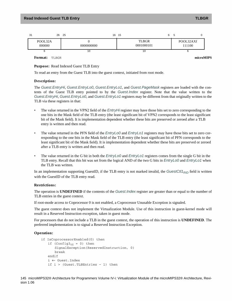
Read Indexed Guest TLB Entry TLBGR
145 microMIPS32® Architecture for Programmers Volume IV-i: Virtualization Module of the microMIPS32® Architecture, Revi-sion 1.06
Format: TLBGR microMIPS
Purpose: Read Indexed Guest TLB Entry
To read an entry from the Guest TLB into the guest context, initiated from root mode.
Description:
The Guest.EntryHi, Guest.EntryLo0, Guest.EntryLo1, and Guest.PageMask registers are loaded with the con-tents of the Guest TLB entry pointed to by the Guest.Index register. Note that the value written to theGuest.EntryHi, Guest.EntryLo0, and Guest.EntryLo1 registers may be different from that originally written to theTLB via these registers in that:
• The value returned in the VPN2 field of the EntryHi register may have those bits set to zero corresponding to theone bits in the Mask field of the TLB entry (the least significant bit of VPN2 corresponds to the least significantbit of the Mask field). It is implementation dependent whether these bits are preserved or zeroed after a TLBentry is written and then read.
• The value returned in the PFN field of the EntryLo0 and EntryLo1 registers may have those bits set to zero cor-responding to the one bits in the Mask field of the TLB entry (the least significant bit of PFN corresponds to theleast significant bit of the Mask field). It is implementation dependent whether these bits are preserved or zeroedafter a TLB entry is written and then read.
• The value returned in the G bit in both the EntryLo0 and EntryLo1 registers comes from the single G bit in theTLB entry. Recall that this bit was set from the logical AND of the two G bits in EntryLo0 and EntryLo1 whenthe TLB was written.
In an implementation supporting GuestID, if the TLB entry is not marked invalid, the GuestCtl1RID field is writtenwith the GuestID of the TLB entry read.
Restrictions:
The operation is UNDEFINED if the contents of the Guest.Index register are greater than or equal to the number ofTLB entries in the guest context.
If root-mode access to Coprocessor 0 is not enabled, a Coprocessor Unusable Exception is signaled.
The guest context does not implement the Virtualization Module. Use of this instruction in guest-kernel mode willresult in a Reserved Instruction exception, taken in guest mode.
For processors that do not include a TLB in the guest context, the operation of this instruction is UNDEFINED. Thepreferred implementation is to signal a Reserved Instruction Exception.
Operation:
if IsCoprocessorEnabled(0) thenif (Config3VZ = 0) then
SignalException(ReservedInstruction, 0)break
endifi ← Guest.Indexif i > (Guest.TLBEntries - 1) then
31 26 25 16 15 6 5 0
POOL32A000000
00000000000
TLBGR0001000101
POOL32AXf111100
6 10 10 6
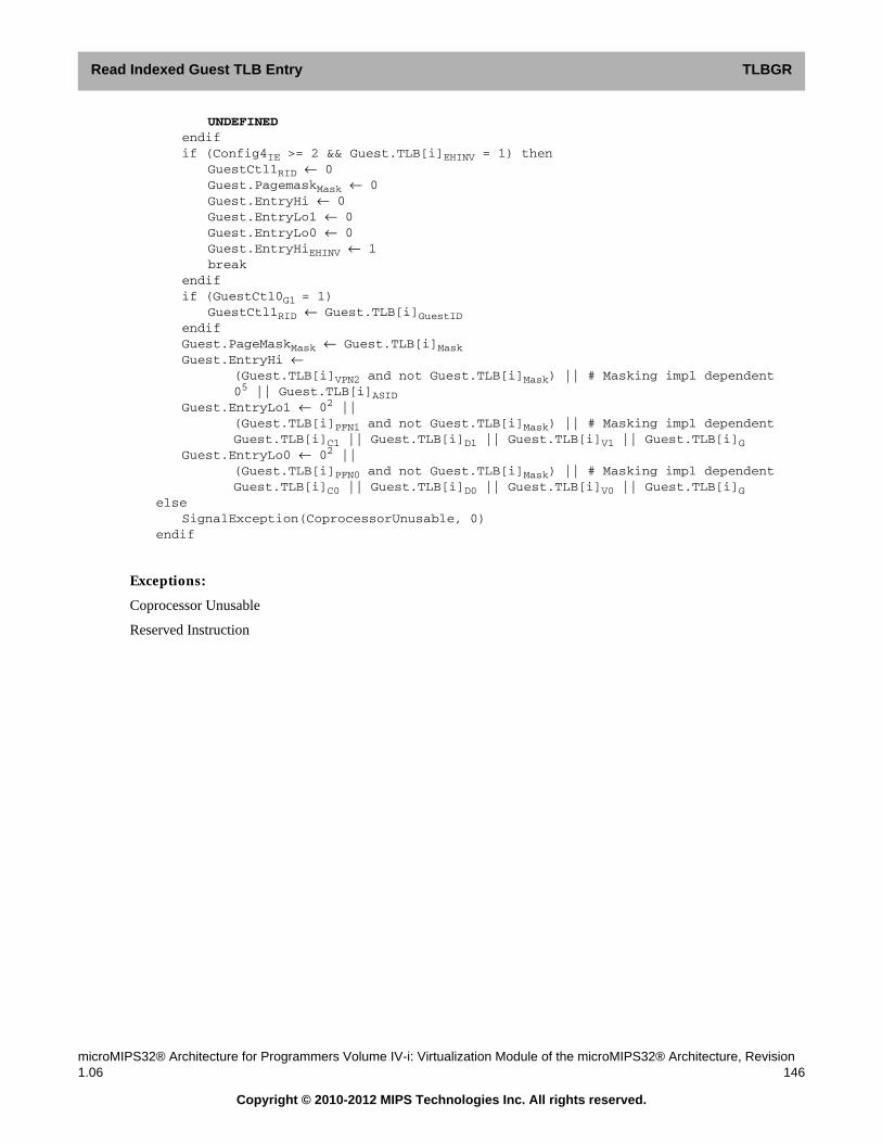
Read Indexed Guest TLB Entry ITLBGR
microMIPS32® Architecture for Programmers Volume IV-i: Virtualization Module of the microMIPS32® Architecture, Revision1.06 146
Copyright © 2010-2012 MIPS Technologies Inc. All rights reserved.
UNDEFINEDendifif (Config4IE >= 2 && Guest.TLB[i]EHINV = 1) then
GuestCtl1RID ← 0Guest.PagemaskMask ← 0Guest.EntryHi ← 0Guest.EntryLo1 ← 0Guest.EntryLo0 ← 0Guest.EntryHiEHINV ← 1break
endifif (GuestCtl0G1 = 1)
GuestCtl1RID ← Guest.TLB[i]GuestIDendifGuest.PageMaskMask ← Guest.TLB[i]MaskGuest.EntryHi ←
(Guest.TLB[i]VPN2 and not Guest.TLB[i]Mask) || # Masking impl dependent05 || Guest.TLB[i]ASID
Guest.EntryLo1 ← 02 ||(Guest.TLB[i]PFN1 and not Guest.TLB[i]Mask) || # Masking impl dependentGuest.TLB[i]C1 || Guest.TLB[i]D1 || Guest.TLB[i]V1 || Guest.TLB[i]G
Guest.EntryLo0 ← 02 ||(Guest.TLB[i]PFN0 and not Guest.TLB[i]Mask) || # Masking impl dependentGuest.TLB[i]C0 || Guest.TLB[i]D0 || Guest.TLB[i]V0 || Guest.TLB[i]G
elseSignalException(CoprocessorUnusable, 0)
endif
Exceptions:
Coprocessor Unusable
Reserved Instruction
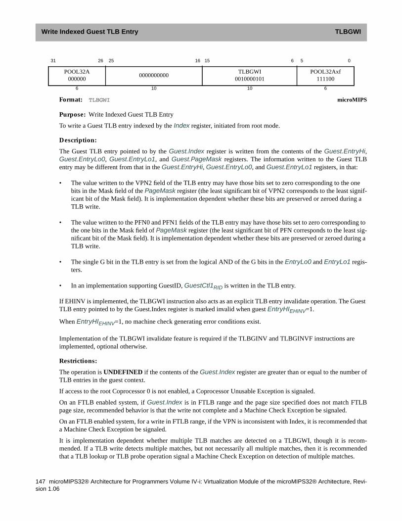
Write Indexed Guest TLB Entry TLBGWI
147 microMIPS32® Architecture for Programmers Volume IV-i: Virtualization Module of the microMIPS32® Architecture, Revi-sion 1.06
Format: TLBGWI microMIPS
Purpose: Write Indexed Guest TLB Entry
To write a Guest TLB entry indexed by the Index register, initiated from root mode.
Description:
The Guest TLB entry pointed to by the Guest.Index register is written from the contents of the Guest.EntryHi,Guest.EntryLo0, Guest.EntryLo1, and Guest.PageMask registers. The information written to the Guest TLBentry may be different from that in the Guest.EntryHi, Guest.EntryLo0, and Guest.EntryLo1 registers, in that:
• The value written to the VPN2 field of the TLB entry may have those bits set to zero corresponding to the onebits in the Mask field of the PageMask register (the least significant bit of VPN2 corresponds to the least signif-icant bit of the Mask field). It is implementation dependent whether these bits are preserved or zeroed during aTLB write.
• The value written to the PFN0 and PFN1 fields of the TLB entry may have those bits set to zero corresponding tothe one bits in the Mask field of PageMask register (the least significant bit of PFN corresponds to the least sig-nificant bit of the Mask field). It is implementation dependent whether these bits are preserved or zeroed during aTLB write.
• The single G bit in the TLB entry is set from the logical AND of the G bits in the EntryLo0 and EntryLo1 regis-ters.
• In an implementation supporting GuestID, GuestCtl1RID is written in the TLB entry.
If EHINV is implemented, the TLBGWI instruction also acts as an explicit TLB entry invalidate operation. The GuestTLB entry pointed to by the Guest.Index register is marked invalid when guest EntryHIEHINV=1.
When EntryHIEHINV=1, no machine check generating error conditions exist.
Implementation of the TLBGWI invalidate feature is required if the TLBGINV and TLBGINVF instructions areimplemented, optional otherwise.
Restrictions:
The operation is UNDEFINED if the contents of the Guest.Index register are greater than or equal to the number ofTLB entries in the guest context.
If access to the root Coprocessor 0 is not enabled, a Coprocessor Unusable Exception is signaled.
On an FTLB enabled system, if Guest.Index is in FTLB range and the page size specified does not match FTLBpage size, recommended behavior is that the write not complete and a Machine Check Exception be signaled.
On an FTLB enabled system, for a write in FTLB range, if the VPN is inconsistent with Index, it is recommended thata Machine Check Exception be signaled.
It is implementation dependent whether multiple TLB matches are detected on a TLBGWI, though it is recom-mended. If a TLB write detects multiple matches, but not necessarily all multiple matches, then it is recommendedthat a TLB lookup or TLB probe operation signal a Machine Check Exception on detection of multiple matches.
31 26 25 16 15 6 5 0
POOL32A000000
0000000000TLBGWI
0010000101POOL32Axf
111100
6 10 10 6

Write Indexed Guest TLB Entry ITLBGWI
microMIPS32® Architecture for Programmers Volume IV-i: Virtualization Module of the microMIPS32® Architecture, Revision1.06 148
Copyright © 2010-2012 MIPS Technologies Inc. All rights reserved.
If multiple match detection is implemented, then on detection, it is recommended that the multiple match be invali-dated and the write completed. It is recommended that no Machine Check Exception be signaled.
The guest context does not implement the Virtualization Module. Use of this instruction in guest-kernel mode willresult in a Reserved Instruction Exception, taken in guest mode.
For processors that do not include a TLB in the guest context, the operation of this instruction is UNDEFINED. Thepreferred implementation is to signal a Reserved Instruction Exception.
Operation:
if IsCoprocessorEnabled(0) thenif (Config3VZ = 0) then
SignalException(ReservedInstruction, 0)break
endifi ← Guest.Indexif (Config4IE >= 2) then
Guest.TLB[i]hardware_invalid ← 0if ( EntryHIEHINV=1 ) then
Guest.TLB[i]hardware_invalid ← 1endif
endifGuest.TLB[i]Mask ← Guest.PageMaskMaskGuest.TLB[i]R ← Guest.EntryHiRGuest.TLB[i]VPN2 ← Guest.EntryHiVPN2 and not Guest.PageMaskMask # Impl dependentGuest.TLB[i]ASID ← Guest.EntryHiASIDGuest.TLB[i]G ← Guest.EntryLo1G and Guest.EntryLo0GGuest.TLB[i]PFN1 ← Guest.EntryLo1PFN and not Guest.PageMaskMask # Impl dependentGuest.TLB[i]C1 ← Guest.EntryLo1CGuest.TLB[i]D1 ← Guest.EntryLo1DGuest.TLB[i]V1 ← Guest.EntryLo1VGuest.TLB[i]PFN0 ← Guest.EntryLo0PFN and not Guest.PageMaskMask # Impl dependentGuest.TLB[i]C0 ← Guest.EntryLo0CGuest.TLB[i]D0 ← Guest.EntryLo0DGuest.TLB[i]V0 ← Guest.EntryLo0Vif (GuestCtl0G1) then
Guest.TLB[i]GuestID ← GuestCtl1RIDendif
elseSignalException(CoprocessorUnusable, 0)
endif
Exceptions:
Coprocessor Unusable
Reserved Instruction
Machine Check (disabled if guest EntryHIEHINV=1.)

Write Random Guest TLB Entry TLBGWR
149 microMIPS32® Architecture for Programmers Volume IV-i: Virtualization Module of the microMIPS32® Architecture, Revi-sion 1.06
Format: TLBGWR microMIPS
Purpose: Write Random Guest TLB Entry
To write a Guest TLB entry indexed by the Random register, initiated from root mode.
Description:
The Guest TLB entry pointed to by the Guest.Random register is written from the contents of the Guest.EntryHi,Guest.EntryLo0, Guest.EntryLo1, and Guest.PageMask registers.
The information written to the Guest TLB entry may be different from that in the Guest.EntryHi, Guest.EntryLo0,and Guest.EntryLo1 registers, in that:
• The value written to the VPN2 field of the Guest TLB entry may have those bits set to zero corresponding to theone bits in the Mask field of the Guest.PageMask register (the least significant bit of VPN2 corresponds to theleast significant bit of the Mask field). It is implementation dependent whether these bits are preserved or zeroedduring a Guest TLB write.
• The value written to the PFN0 and PFN1 fields of the TLB entry may have those bits set to zero corresponding tothe one bits in the Mask field of Guest.PageMask register (the least significant bit of PFN corresponds to theleast significant bit of the Mask field). It is implementation dependent whether these bits are preserved or zeroedduring a Guest TLB write.
• The single G bit in the Guest TLB entry is set from the logical AND of the G bits in the Guest.EntryLo0 andGuest.EntryLo1 registers.
• In an implementation supporting GuestID, GuestCtl1RID is written in the TLB entry.
Restrictions:
If access to Coprocessor 0 is not enabled, a Coprocessor Unusable Exception is signaled.
On an VTLB/FTLB enabled implementation, if the Pagemask register contains a page size differing from the FTLBpage size defined in Config4, then the write goes into a random entry in the VTLB.
It is implementation dependent whether multiple TLB matches are detected on a TLBGWR, though it is recom-mended. If a TLB write detects multiple matches, but not necessarily all multiple matches, then a TLB lookup or TLBprobe operation should signal a Machine Check Exception on detection of multiple matches.
If multiple match detection is implemented, then on detection, the multiple match should be invalidated and the writecompleted. No Machine Check Exception should be signaled.
The guest context does not implement the Virtualization Module. Use of this instruction in guest-kernel mode willresult in a Reserved Instruction exception, taken in guest mode.
For processors that do not include a TLB in the guest context, the operation of this instruction is UNDEFINED. Thepreferred implementation is to signal a Reserved Instruction Exception.
Operation:
if IsCoprocessorEnabled(0) thenif (Config3VZ = 0) then
31 26 25 16 15 6 5 0
POOL32A000000
0000000000TLBGWR
0011000101POOL32Axf
111100
6 10 10 6

Write Random Guest TLB Entry ITLBGWR
microMIPS32® Architecture for Programmers Volume IV-i: Virtualization Module of the microMIPS32® Architecture, Revision1.06 150
Copyright © 2010-2012 MIPS Technologies Inc. All rights reserved.
SignalException(ReservedInstruction, 0)break
endifi ← Guest.Randomif (Config4IE >= 2) then
Guest.TLB[i]hardware_invalid ← 0if ( EntryHIEHINV=1 ) then
Guest.TLB[i]hardware_invalid ← 1endif
endifGuest.TLB[i]Mask ← Guest.PageMaskMaskGuest.TLB[i]R ← Guest.EntryHiRGuest.TLB[i]VPN2 ← Guest.EntryHiVPN2 and not Guest.PageMaskMask # Impl. dependentGuest.TLB[i]ASID ← Guest.EntryHiASIDGuest.TLB[i]G ← Guest.EntryLo1G and Guest.EntryLo0GGuest.TLB[i]PFN1 ← Guest.EntryLo1PFN and not PageMaskMask # Impl. dependentGuest.TLB[i]C1 ← Guest.EntryLo1CGuest.TLB[i]D1 ← Guest.EntryLo1DGuest.TLB[i]V1 ← Guest.EntryLo1VGuest.TLB[i]PFN0 ← Guest.EntryLo0PFN and not PageMaskMask # Impl. dependentGuest.TLB[i]C0 ← Guest.EntryLo0CGuest.TLB[i]D0 ← Guest.EntryLo0DGuest.TLB[i]V0 ← Guest.EntryLo0Vif (GuestCtl0G1) then
Guest.TLB[i]GuestID ← GuestCtl1RIDendif
elseSignalException(CoprocessorUnusable, 0)
endif
Exceptions:
Coprocessor Unusable
Reserved Instruction
Machine Check (implementation dependent)

TLB Invalidate Flush TLBINVF
151 microMIPS32® Architecture for Programmers Volume IV-i: Virtualization Module of the microMIPS32® Architecture, Revi-sion 1.06
Format: TLBINVF microMIPS
Purpose: TLB Invalidate Flush
Description:
The TLBINVF instruction is unmodified from the base architectural definition, except in an implementation support-ing GuestID:
• When executing in Guest mode, if the GuestID read does not match GuestCtl1ID, then the TLB entry is notmodified.
• When executing in Root mode, if the GuestID read does not match GuestCtl1RID, then the TLB entry is notmodified. Note that this only applies to the root TLB, invalidation of guest virtual address translations requiresexecution of the equivalent TLBGINVF instruction sequence to modify the guest TLB.
Restrictions:
Unchanged from the base architecture.
Exceptions:
Coprocessor Unusable
Reserved Instruction
31 26 25 16 15 6 5 0
POOL32A000000
0000000000TLBINV
0101001101POOL32Axf
111100
6 10 10 6

TLB Invalidate Flush ITLBINVF
microMIPS32® Architecture for Programmers Volume IV-i: Virtualization Module of the microMIPS32® Architecture, Revision1.06 152
Copyright © 2010-2012 MIPS Technologies Inc. All rights reserved.

TLB Invalidate TLBINV
153 microMIPS32® Architecture for Programmers Volume IV-i: Virtualization Module of the microMIPS32® Architecture, Revi-sion 1.06
Format: TLBINV microMIPS
Purpose: TLB Invalidate
Description:
The TLBINV instruction is unmodified from the base architectural definition, except in an implementation supportingGuestID:
• When executing in Guest mode, if the GuestID read does not match GuestCtl1ID, then the TLB entry is notmodified.
• When executing in Root mode, if the GuestID read does not match GuestCtl1RID, then the TLB entry is notmodified. Note that this only applies to the root TLB, invalidation of guest virtual address translations requiresexecution of the equivalent TLBGINV instruction sequence to modify the guest TLB.
Restrictions:
Unchanged from the base architecture.
Exceptions:
Unchanged from the base architecture.
31 26 25 16 15 6 5 0
POOL32A000000
0000000000TLBINV
0100001101POOL32Axf
111100
6 10 10 6

Probe TLB for Matching Entry ITLBP
microMIPS32® Architecture for Programmers Volume IV-i: Virtualization Module of the microMIPS32® Architecture, Revision1.06 154
Copyright © 2010-2012 MIPS Technologies Inc. All rights reserved.
Format: TLBP microMIPS
Purpose: Probe TLB for Matching Entry
To find a matching entry in the TLB.
Description:
The TLBP instruction is unmodified from the base architectural definition, except in an implementation supportingGuestID:
• When executing in Guest mode, if the GuestID read does not match GuestCtl1ID, then the match fails.
• When executing in Root mode, if the GuestID read does not match GuestCtl1RID, then the match fails.
Restrictions:
Unchanged from the base architecture.
Operation:
if IsCoprocessorEnabled(0) thenIndex ← 1 || UNPREDICTABLE31
for i in 0...TLBEntries-1if ((TLB[i]VPN2 & ~(TLB[i]Mask)) = (EntryHiVPN2 & ~(TLB[i]Mask))) and
(Config4IE >= 2 && TLB[i]hardware_invalid != 1) and((IsRootMode() and (TLB[i]GuestID = GuestCtl1RID)) or(IsGuestMode() and (TLB[i]GuestID = GuestCtl1ID))) and((TLB[i]G = 1) or (TLB[i]ASID = EntryHiASID))thenIndex ← i
endifendfor
elseSignalException(CoprocessorUnusable, 0)
endif
Exceptions:
Coprocessor Unusable
Reserved Instruction
Machine Check (implementation defined)
31 26 25 16 15 6 5 0
POOL32A000000
00000000000
TLBP0000001101
POOL32AXf111100
6 10 10 6

Probe TLB for Matching Entry TLBP
155 microMIPS32® Architecture for Programmers Volume IV-i: Virtualization Module of the microMIPS32® Architecture, Revi-sion 1.06

Read Indexed TLB Entry ITLBR
microMIPS32® Architecture for Programmers Volume IV-i: Virtualization Module of the microMIPS32® Architecture, Revision1.06 156
Copyright © 2010-2012 MIPS Technologies Inc. All rights reserved.
Format: TLBR microMIPS
Purpose: Read Indexed TLB Entry
To read an entry from the TLB.
Description:
The TLBR instruction is unmodified from the base architectural definition, except in an implementation supportingGuestID:
• When executing in Guest mode, if the GuestID read does not match GuestCtl1ID, then the TLB related CP0 reg-isters are zeroed and EHINV is set to 1.
• When executing in Root mode and the TLB entry is not marked as invalid, GuestCtl1RID is set to the GuestID ofthe TLB entry read, else it is set to 0.
Restrictions:
The operation is UNDEFINED if the contents of the Index register are greater than or equal to the number of TLBentries in the processor.
If access to Coprocessor 0 is not enabled, a Coprocessor Unusable Exception is signaled.
For processors that do not include the standard TLB MMU, the operation of this instruction is UNDEFINED. Thepreferred implementation is to signal a Reserved Instruction Exception.
Operation:
if IsCoprocessorEnabled(0) theni ← Indexif i > (TLBEntries - 1) then
UNDEFINEDendifif (Config4IE >= 2 && TLB[i]hardware_invalid=1) then
if GuestCtl0G1=1if (GuestCtl0GM=0 or (GuestCtl0GM=1 and (Root.DebugDM=1 or
Root.StatusERL=1 or Root.StatusEXL=1))) thenGuestCtl1RID ← 0 // RID only updated in root mode
endifendif// Remaining state is handled similarly in root and guest modes.PagemaskMask ← 0EntryHi ← 0EntryLo1 ← 0EntryLo0 ← 0EntryHiEHINV ← 1break
endifPageMaskMask ← TLB[i]MaskEntryHi ←
(TLB[i]VPN2 and not TLB[i]Mask) || # Masking implementation dependent05 || TLB[i]ASID
31 26 25 16 15 6 5 0
POOL32A000000
00000000000
TLBR0001001101
POOL32AXf111100
6 10 10 6

Read Indexed TLB Entry TLBR
157 microMIPS32® Architecture for Programmers Volume IV-i: Virtualization Module of the microMIPS32® Architecture, Revi-sion 1.06
EntryLo1 ← 02 ||(TLB[i]PFN1 and not TLB[i]Mask) || # Masking mplementation dependentTLB[i]C1 || TLB[i]D1 || TLB[i]V1 || TLB[i]G
EntryLo0 ← 02 ||(TLB[i]PFN0 and not TLB[i]Mask) || # Masking mplementation dependentTLB[i]C0 || TLB[i]D0 || TLB[i]V0 || TLB[i]G
# if in guest mode, if the TLB entry guest id != guest id then zero the resultif (GuestCtl0G1 = 1)
if (GuestCtl0GM=1) and (Root.DebugDM=0) and(Root.StatusERL=0) and (Root.StatusEXL=0) then
if (TLB[i]ID != GuestCtl1ID) thenPagemaskMask ← 0EntryHi ← 0EntryLo1 ← 0EntryLo0 ← 0EntryHiEHINV ← 1
endifelse #in root mode, RID with GuestID
GuestCtl1RID ← TLB[i]GuestIDendif
endifelse
SignalException(CoprocessorUnusable, 0)endif
Exceptions:
Coprocessor Unusable
Reserved Instruction

Read Indexed TLB Entry ITLBR
microMIPS32® Architecture for Programmers Volume IV-i: Virtualization Module of the microMIPS32® Architecture, Revision1.06 158
Copyright © 2010-2012 MIPS Technologies Inc. All rights reserved.

Write Indexed TLB Entry TLBWI
159 microMIPS32® Architecture for Programmers Volume IV-i: Virtualization Module of the microMIPS32® Architecture, Revi-sion 1.06
Format: TLBWI microMIPS
Purpose: Write Indexed TLB Entry
To write a TLB entry indexed by the Index register.
Description:
The TLBWI instruction is unmodified from the base architecture, except in an implementation supporting GuestID:
• When executing in Guest mode, GuestCtl1ID is written in the guest TLB entry.
• When executing in Root mode GuestCtl1RID is written in the root TLB entry.
It is expected that a Guest entry in the Root TLB must have its Global(G) bit set to 1 on a TLB write. This is becausethe ASID field is not applicable for a Guest entry in the Root TLB.
If EHINV is implemented, the TLBWI instruction also acts as an explicit TLB entry invalidate operation. The TLBentry pointed to by the Index register is marked invalid when EntryHIEHINV=1.
When EntryHIEHINV=1, no machine check generating error conditions exist.
Restrictions:
Unmodified from the base architecture.
Operation:
if IsCoprocessorEnabled(0) theni ← Indexif ( Config4IE >= 2) then
TLB[i]hardware_invalid ← 0if (EntryHIEHINV=1) then
TLB[i]hardware_invalid ← 1endif
endifTLB[i]Mask ← PageMaskMaskTLB[i]VPN2 ← EntryHiVPN2 and not PageMaskMask # Implementation dependentTLB[i]ASID ← EntryHiASIDif (GuestCtl0G1) then
if ((GuestCtl0RAD=0) and IsRootMode() and (GuestCtl1RID != 0))TLB[i]G ← 1
elseTLB[i]G ← EntryLo1G and EntryLo0G
endifelse
TLB[i]G ← EntryLo1G and EntryLo0Gendifif ( IsRootMode() ) then
TLB[i]GuestID ← GuestCtl1RIDelse
TLB[i]GuestID ← GuestCtl1ID
31 26 25 16 15 6 5 0
POOL32A000000
0000000000TLBWI
0010001101POOL32Axf
111100
6 10 10 6

Write Indexed TLB Entry ITLBWI
microMIPS32® Architecture for Programmers Volume IV-i: Virtualization Module of the microMIPS32® Architecture, Revision1.06 160
Copyright © 2010-2012 MIPS Technologies Inc. All rights reserved.
endifTLB[i]PFN1 ← EntryLo1PFN and not PageMaskMask # Implementation dependentTLB[i]C1 ← EntryLo1CTLB[i]D1 ← EntryLo1DTLB[i]V1 ← EntryLo1VTLB[i]PFN0 ← EntryLo0PFN and not PageMaskMask # Implementation dependentTLB[i]C0 ← EntryLo0CTLB[i]D0 ← EntryLo0DTLB[i]V0 ← EntryLo0V
elseSignalException(CoprocessorUnusable, 0)
endif
Exceptions:
Unmodified from the base architecture.

Write Indexed TLB Entry TLBWI
161 microMIPS32® Architecture for Programmers Volume IV-i: Virtualization Module of the microMIPS32® Architecture, Revi-sion 1.06

Chapter 7
microMIPS32® Architecture for Programmers Volume IV-i: Virtualization Module of the microMIPS32® Architecture, Revision1.06 162
Copyright © 2010-2012 MIPS Technologies Inc. All rights reserved.
Notes
This Virtualization Module specification is a work in progress. Feedback and comments are welcomed on the func-tional behavior, and the explanations of that behavior.
7.1 Potential areas of improvement
The following items have been identified as potential areas of improvement in the specification.
• Extensions to EJTAG specification to allow additional control over hardware breakpoints used during guest exe-cution.
• Consider options to allow for translation of 36-bit physical addresses
• Consider options to reduce the cost of guest0-guest1-guest0 context switching.
• Security: JTAG, DEBUG, Boot, IOMMU

Notes
163 microMIPS32® Architecture for Programmers Volume IV-i: Virtualization Module of the microMIPS32® Architecture, Revi-sion 1.06
Copyright © 2010-2012 MIPS Technologies Inc. All rights reserved.

Appendix A
microMIPS32® Architecture for Programmers Volume IV-i: Virtualization Module of the microMIPS32® Architecture, Revision1.06 164
Copyright © 2010-2012 MIPS Technologies Inc. All rights reserved.
Revision History
In the left hand page margins of this document you may find vertical change bars to note the location of significantchanges to this document since its last release. Significant changes are defined as those which you should take note ofas you use the MIPS IP. Changes to correct grammar, spelling errors or similar may or may not be noted with changebars. Change bars will be removed for changes which are more than one revision old.
Please note: Limitations on the authoring tools make it difficult to place change bars on changes to figures. Changebars on figure titles are used to denote a potential change in the figure itself.
Version Date Comments
0.02 18-Aug-09 First paravirtualization spec for internal consumption.
0.03 21-Aug-09 Changes:• First full virtualization spec for internal consumption.• Revisions to paravirtualization spec as a result of full virtualization updates.
0.04 18-Sep-09 Changes:• Modified PageMaskKE bit description
• Removed L2V0/1 from TLB entry, kept GP0/1• Changed all ‘real-physical’ references to ‘root-physical’• Renamed GuestCtl02 to GuestID
0.05 22-Sep-09 Changes:• Replaced upper-half configuration registers SegmentCtl/SegmentCtl2 with
Segment Configuration system covering full virtual address space.• Re-arranged sections to lighten load in overview chapters.• Removed generic chapters - “About This Book” and “Guide To The Instruc-
tion Set”
0.06 31-Mar-10 Significant revisions, including:• Combined introductory chapters• Root and guest mode follow consistent rules, clarified transitions between
modes.• Removed spec duplication with MIPS32 where possible• Address translation uses guest TLB as first level, root TLB used for second
level• Added direct assignment of interrupts• Added timer support

Revision History
165 microMIPS32® Architecture for Programmers Volume IV-i: Virtualization Module of the microMIPS32® Architecture, Revi-sion 1.06
Copyright © 2010-2012 MIPS Technologies Inc. All rights reserved.
0.07 1-Jun-10 Changes:• Fixed many typos• Changed how guest timer interrupt is applied (pseudocode)• Expanded description of EIC use with guest mode• Clarified use of CauseDC.
• Moved HYPCALL to COP0 opcode, changed from RI to CU exception whenused from guest-user mode
• Requires v3.00 of Volume III (PRA) rather than 2.80. Removed descriptionsof Context and ContextConfig. Added RI, XI bits and related exceptions.
• Renamed Segment Control modes, added UKSU unmapped, unrestrictedmode.
• Changed segmentation scheme to remove fall-back to MIPS32 when Statu-sERL=1. Changes required to segment control registers and EBase. Adjusted
scheme to incorporate FMT and BAT translation systems. Allowed imple-mentation-dependent number of segments.
• Moved MTGC0 and MFGC0 onto the same sub-opcode, bit 3 selects.• Adjusted description of guest mode entry with ERET.• Moved PageGrain KE bit to avoid clash with IEC bit.• Section covering UNDEFINED and UNPREDICTABLE and guest mode.• Revised hardware page table walking scheme• Added BadInstr register for faulting instruction word• Added Guest Reserved Instruction Redirect exception• Added additional description to GTOffset register• Guest mode and Debug mode are mutually exclusive• Added section describing design intent of features, how they are expected to
be used by hypervisor software.• Added TLBGP, TLBGWR• Added description of shadow register set operation• Added MIPS64 support
0.08 4-Jun-10 Changes:• Identified BadInstr as a future base architecture feature• Changed guest-mode TLB enable from writable Guest.ConfigMT to new field
GuestCtl0ST.
• Fixed minor typos
0.09 07-Jul-10 • Merge GuestCtl0ST and GuestCtl0AT fields into one encoded field as not all
combinations of the 2 bits make sense.
0.10 03-Mar-11 • Removed non-virtualization specific functionality to CP0 enhancement pro-posal.
0.11 14-Sep-11 Added Guest TLB invalidate instructions.Updated HYPCALL field size.Updated TLBGWI pseudo-code for EHINV use.
0.12 December 20, 2011 Minor corrections/enhancements.Count register added to those available in Guest CP0 context.(Impl) Implementation defined fields added to GuestCTL0 register.Config5 addition noted.Noted that a TLB related machine check exception is taken in current mode,rather than always root.Dropped GuestCtl0.AT=0 mode, pending further review.Clarified Guest Watch exception behavior.Noted that an exception caused by Root level address translation initiated by aGuest address translation is not a Guest level TLB related exception.
Version Date Comments

microMIPS32® Architecture for Programmers Volume IV-i: Virtualization Module of the microMIPS32® Architecture, Revision1.06 166
Copyright © 2010-2012 MIPS Technologies Inc. All rights reserved.
0.13 January 11, 2012 Minor corrections/enhancements.Guest/Root Watch support defined and enhanced.Added Guest Mode change exception.Updated Guest Field change definition.Clarified entry to Guest mode definition.Enhanced definition of Guest/Root TLB based address translation.Improved GuestID definition.Improved definition of TLBR behavior in Guest mode.Extended Guest/Root CP0 register availability definition.Improved Guest initiated Root TLB exception handling definition.Enhanced exception priority definitions.Added Guest exception codes for GVA, GPA recognitionAdded RID field to GuestCtl1 register, supplies last Guest ID read.
0.14 January 12, 2012 Added optional PerfCnt support (GM, RM fields).
0.15 February 29, 2012 Updated GuestCtl1 RID/ID definition.Added definition of behavioral changes caused by GuestID to TLB lookup andTLB instructions.Renamed Guest Field/Mode Change exceptions to Guest Software FiledChange/Guest Hardware Field Change exceptions.Updated Performance Counter, Watch register descriptions.Updated Interrupt behavior definition.GuestCtl0.PT (PIP implemented) added.Added TLBWI to note G=1 behavior.Defined SRSCtl/SRSMap as not available in Guest context.PSI renamed to GPSI for consistency with Guest Exception names.
0.16 May 18, 2012 Clarified that GPSI for guest use of RDHWR is signaled only if guest CP0 reg-isters are present and enabled by HWREna and GuestCtl0.CPO=0.TLBR and TLBGR instructions set EntryHi, EntryLo0, EntryLo1, Page-Mask.mask and GuestCtl1.RID to zero on read of an invalid TLB entry or inguest mode when the current guest id does not match the guest id in the TLBentry read.
Version Date Comments

Revision History
167 microMIPS32® Architecture for Programmers Volume IV-i: Virtualization Module of the microMIPS32® Architecture, Revi-sion 1.06
Copyright © 2010-2012 MIPS Technologies Inc. All rights reserved.
0.17 June 8, 2012 Root/Guest TLB invalidate instructions only apply to Root/Guest TLB’s. Clari-fied use of GuestCtl1.ID/RID field usage by TLB instructions: TLBR, TLBWI,TLBGWI, TLBGWR.Clarified use of EHINV by TLB instructions: TLBR, TLBGR, TLBP, TLBWI,TLBGWI, TLBGWR.Change MC to recommended on FTLB page size match, FTLB write with VPNinconsistent with Index, and multiple match on TLBGWI.Updated MFGC0, MTGC0 to contain recent MIPS32 RI/XI bit changes.DMTGC0 assignment typo fixed.Table 4.2 GuestCtl0 register field descriptions:PWCtl added to list of GPSI triggering registers.Index, Random EntryLo0/1, Context, XContext, COntextConfig, PageMask andEntryHi dropped from list of GPSI triggering registers.Table 3.5 Count: GuestCtl0.GT added as a modifier triggering GPSI.Mention of potential support of recursive virtualization deleted to avoid confu-sion.Table 3.16 guest TLB was noted as optional, it’s required.Watchpoint debug moved to seperate section.Table 3.13 reference to dmseg removed.Sec. 3.8.2 Clarified, assign performance counters to guest or root, not both.Sec. 3.8 Interrupts. clarified PIP and other behavior under development.Sec. 3.7.8 Clarified handler ERET behavior requirements.Sec. 3.7.7 Added PWCtl to GPSI triggering list.Sec. 3.7.5 Added GRIR to Exception Vector Locations list.Table 3.10 priority of GSFC placed above Execution Exception since it onlyoccurs on (D)MTC0 instruction execution and suppresses execution.Sec. 3.7.3 typo on GExcCode fixed.Sec. 3.7.2 Added TLB Execute-Inhibit and Read-Inhibit to TLB exceptionswhich update BadVaddr.Table 3.7 Added Status {CU3..0, PX,KX,SX, UX} and PerfCtl.Control to GuestCP0 fields subject to Software or Hardware field change Exceptions.Table 3.5 DEPC, DESAVE added. XContextConfig made optional.Sec. 3.5 Error in pseudo-code fixed. (now returns Guest CCA).Sec. 3.4.3.6 Attempted to clarifiy operating mode definition.Added Config4.IE=1 check to describe optionality of EHINV in TLBGWI,TLBWI, TLBP, TLBGP, TLBR and TLBGR instruction pseudo-code.Description of Guest/Root Cause.IP added.
Version Date Comments

microMIPS32® Architecture for Programmers Volume IV-i: Virtualization Module of the microMIPS32® Architecture, Revision1.06 168
Copyright © 2010-2012 MIPS Technologies Inc. All rights reserved.
0.18 July 5, 2012 (Lists changes that may impact architecture or implementation.. No clarifica-tions noted.)Added Section 4.5.1 - Virtualized MMU GuestID Use- Changed pseudo-code in Section 4.5 accordingly.Rewrote Section 4.8.1 on External Interrupts - Detail handling plus VirtualInterrupt handling.Table 4.12 “Priority of Exceptions Table”- Machine Check Asynchronous. Described event accurately. Split out guestrelated events to reposition below GHFC.- Machine Check Synchronous. Added event. Position below Instruction Valid-ity.- Repositioned Deferred Watch Guest below GHFC.- GSFC has been repositioned below Instruction Validity.- GRR has been repositioned below Instruction Validity.Table 4.11 “Guest CP0 Read-only fields writeable from Root mode”- Remove PCI,SR,NMI.Updated Section 4.12 “Watchpoint Debug Support”- Table 4.17: Added column for Guest exception on Access.- Added para for sharing policy.Section 4.8. “Performance Counter Interrupts”- Changed UNDEFINED to UNPREDICTABLE.- Added para for sharing policy- Added para for root control of guest PCI state.Table 4.7: “CP0 Registers in Guest CP0 context”- ContextConfig, XContextConfig: Remove presence of TLB as qualifying con-dition to determine presence of these registers.Section 4.7.8 “Guest Software Field Change Exception”- setting TS by h/w can cause GSFC in lieu of GHFC.- added description for optional GuestCtl0SRC/SFK.Modified Section 4.8.2 “Derivation of Guest.Cause.IP” pseudo-code to includeVirtual Interrupts”.
Version Date Comments

Revision History
169 microMIPS32® Architecture for Programmers Volume IV-i: Virtualization Module of the microMIPS32® Architecture, Revi-sion 1.06
Copyright © 2010-2012 MIPS Technologies Inc. All rights reserved.
0.19 August 15, 2012 Owner: sanjay// Only lists new functionality or modifications to existing functionality. Minorself-evident changes not listed.Page 9. Table 2.5 Added missing WAIT/ERET/DERETPage 19. 4.4.3.1. Added subroutines IsGuestMode and IsRootMode. Used inpseudo-code throughout.Page 22. 4.4.4. Only guest writes constrained.Pages 28-29. 4.5. pseudo-code corrected for RAD/DRG use.Page 30, 4.5.1. Mention that RAD/DRG need not be Read-only.Page 31, 4.5.1. Modified pseudo-code for RAD/DRG use.Page 39, Table 4.5.1. SRSCtl/Map now Optional instead of Not_Available.Page 42, Table 4.9.- Miscellaneous changes.- PerfCnt event fields added as causing GSFC.Page 44, Table 4.11- Added SR/NMI back. Now Optional.- Added BadInstr.InstrP from COP0 Enhancement Spec.Page 51, Table 4.12:- Moved guest Machine-Check Async back to original priority.- Moved guest Deferred Watch back to original priority.- Above two had been shifted because of GHFC. Now resolved.- Page 53, Table 4.12- GHFC positioned below Instruction Validity.Page 56, 4.7.7- Count and Compare - should only cause GPSI if enabled.Page 57, 4.7.8- Miscellaneous changes.- Added PerfCnt.Event, if under guest ctl, to list.Page 59, 4.7.8- UM/KSU GSFC enabled by GuestCtl0.MC- Added GuestCtl0.SFC1/SFC2.- Added PerfCnt.EventPage 61, 4.7.9- Mention atomic handling of GHFC exception.Page 64, 4.8.1- Rewrote section on Non-EIC Interrupt Handling.- Introduce GuestCtl2.SCVIP.Page 67, 4.8.2- Modified GuestInterruptPending.- Removed Guest.Cause.IP[1:0] or’ing from EIC mode.- Added Guest.Cause.IP[1:0] or’ing into non-EIC mode.Page 69, 4.8.4- Added conditions under which guest access to PerfCnt causes GPSI.- Enhanced description for simultaneous sharing of PerfCnt.Page 70, 4.9.1- Rewrote virtualized Shadow Set control.Page 72, 4.10- Rewrote emulation of MT Module in guest context.Page 76, Table 4.17- Removed GPSI from “Guest Exception on Match” column,.Page 77, 4.12- Enhanced description for simultaneous sharing of Watch Register.Page 85, Table 5.1- Added GuestCtl2. Corrected Section #s.
Version Date Comments

microMIPS32® Architecture for Programmers Volume IV-i: Virtualization Module of the microMIPS32® Architecture, Revision1.06 170
Copyright © 2010-2012 MIPS Technologies Inc. All rights reserved.
0.19 August 15, 2012 Page 87, Table 5.2- GuestCtl0.MC now includes UM/KSU.Page 90, Table 5.2- GuestCtl0.CG can be R0 - implementation dependent.Page 92, Table 5.2- Added GuestCtl0.G2- SFC,SFK changed to SFC2,SFC1Page 95, Section 5.4- GuestCtl2 is new.Page 105, Table 6.1- TLBWR is new.Page 117, TLBGINV Operation- Added test for GuestID,.- VPN2_invalid changed to hardware_invalid.Page 119, TLBGINVF Operation- Added test for GuestID,.- VPN2_invalid changed to hardware_invalid.Page 121, TLBGP- Added test for GuestID,Page 127, TLBGWI- Added test for GuestIDPage 129, TLBGWR- Added test for GuestIDPage 133, TLBP- Changed inRoot/GuestMode to IsRoot/GuestModePage 136, TLBR- Added test for GuestIDPage 138, TLBWI- Added test for GuestID- Guest Entries are globalized for RAD=0Page 141, TLBWR- - Added test for GuestID- Guest Entries are globalized for RAD=0Note : For v0.20, add operation section for any instruction impacted by Gues-tID.
Version Date Comments

Revision History
171 microMIPS32® Architecture for Programmers Volume IV-i: Virtualization Module of the microMIPS32® Architecture, Revi-sion 1.06
Copyright © 2010-2012 MIPS Technologies Inc. All rights reserved.
0.20 September 7, 2012 // Updated Virtual Interrupt Handling. These changes are meant to//keep compatibility between two different implementations on//non-EIC mode.GuestCtl2.SCVIP converted to GuestCtl2.HC. Changed 4.8.1.1 accordingly.Made reset state of GuestCtl2.HC implementation dependent.In GuestCtl2, shifted current SCVIP field left by 1b. Removed M bit asGuestCtl3 presence can be detected through other means.// Following edits are meant only for low end VZ implementations.Added GuestCtl0.FCE, Field Change exception Enable. Allows disable of cor-responding exceptions. Optional for high-end implementations.Added GuestCtl0.AT=2. This is to indicate that a Root Protection Unit is sup-ported.// Following edits meant for External Interrupt Controller root intervention sup-port.New Section 4.8.1.2 for EIC Interrupt HandlingAdded GuestCtl1.EID - External Interrupt Controller (EIC) GuestID.Section 4.8.1.2 - add comment about GuestID requirements for root and guestbuses.Add GuestCtl2 definition for EIC mode.// Following edits meant for virtualized Shadow SetsSection 4.9.1 - Describe scheme for virtual sharing of Shadow Sets.Added HSS,EICSS,CSS to Table 4.11 as root writeable read-only fields in guestSRSCtl.Added GuestCtl3.// MiscellaneousChanged GuestCtl0.FCE to FCD. This is to make compatible with existingimplementations.
0.21 September 22, 2012 Table 4.12, Priority of Exceptions. Add type of exception to InstructionCache/Bus Error. Missing.Section 4.8.2 Changed non-EIC pseudo-code for interrupts.- Inserted r<<2 earlier to accommodate IPTI and IPPCI. Both are 3b values andcan shift upto 7.- Recoded slightly to indicate Guest.Cause.IP is not a term that is ORed into theequation.Section 4.8.1.2. Modified GuestCtl0.PIP paragraph to allow control of guestinterrupts in EIC mode.
Version Date Comments

microMIPS32® Architecture for Programmers Volume IV-i: Virtualization Module of the microMIPS32® Architecture, Revision1.06 172
Copyright © 2010-2012 MIPS Technologies Inc. All rights reserved.
0.22 November 4, 2012November 27, 2012
- Section 4.8 - Changed wording of 3rd bullet of set of pending interrupts. Rootinterrupt njection through GuestCtl2.VIP and GRIPL.- Modified pseudo-code in Section 4.8.2 to include virtual RIPL inclusion inEIC interrupts.- Section 4.9.1 : Guest cannot write Guest SRSCtl.ESS/PSS. Modified 3rd lastpara to reflect contradiction.- Section 5.2, GuestCtl0.AT=2 is now listed as optional. AT=2 is VZ-lite option.- Section 4.8.2 EIC pseudo-code corrected - EIC interrupt level is only qualifiedby Root.Status.IPL.- Section 4.6.8. Added text to clarify purpose of pseudo-code, and specify dif-ferent methods for restoring guest timer.- Section 4.8.1.1 : non-EIC handling. Described NetL compatible mode forinjecting interrupt into guest context. This mode supported before virtual inter-rupt injection was added.- Updated 4.8.1.2, EIC Handling. Allow auto-update of guest RIPL and EICSSfrom GuestCtl2 on guest entry.- Added GuestCtl0Ext for additional GPSI enables for Virtuoso.- Shifted GuestCtl0.FCD to GuestCtl0Ext- Added GuestCtl0.G0E as GuestCtl0Ext presence bit.- In section 4.8.2 correction - EICGuestLevel compared against Guest.Sta-tus.IPL instead of Root.Status.IPL.- Section 4.12 Clarified guest access to Watch for Guest Config1.WR=0/1.- Added recommendation to Restriction section for TLBWR and TLBGWR.The recommendation is for handling Random and Index overlap on write.
1.00 December 7, 2012 Copy of 0.22 for Release 5 of architecture.
1.01 January 10, 2013 - Add GuestCtl0Ext.CGI to allow guest to execute CACHE index invalidateinstructions.-Remove GuestCtl0.AT=2. This was meant to indicate presence of Root Protec-tion Unit. software will instead detect RPU through Config3.VZ and Root.Con-fig.MT=3(FMT)..- In section 4.8.1.2, replace all references to IRET with ERET.- In section 4.8.1.2, update text on STOP protocol.- Updated Table 4.11. Root write to Guest.Cause.IP/RIPL is now optional.Made optional because if GuestCtl2.VIP/GRIPL are implemented then rootdoes not need to write these fields.- Updated Figure 4.11 to show that guest-user hypcall can cause transition toroot if Guest.Status.CU0=1.- Updated GuestCtl1.PIP to indicate PIP only applicable in non-EIC mode.Removed reference to PIP in section 4.8.1.2.- Removed reference to PIP in section 4.8.2, showed prioritization ofEICGuestLevel and GuestCtl2.RIPL. It was assumed before thatEICGuestLevel was higher priority.- Added reserved ASE fields to GuestCtl2 for MCU ASE.- Added Section 4.7.12 to describe setting of Root.Cause.ExcCode andGuestCtl2.GExcCode.- Updated Section 4.7.9 for recommended method of handling GHFC.
Version Date Comments

Revision History
173 microMIPS32® Architecture for Programmers Volume IV-i: Virtualization Module of the microMIPS32® Architecture, Revi-sion 1.06
Copyright © 2010-2012 MIPS Technologies Inc. All rights reserved.
1.02 February 19th, 2013 - Fix typo in Section 4.7.9. GuestCtl2.GExcCode should be GuestCtl0.GExc-Code.- Section 4.8.1.2. Removed comment about timeout. We have specified and sup-port a method for correct functionality. Thus, redundant.- Section 5.3, Table 5.4. Change EID field to read-only if implemented. WasR/W.- Section 4.8.2 (pseudocode). Modified GuestCtl0.PT qualification. AddedGuestCtl0.G2 qualification for optional interrupt passthrough.- Section 4.5.1 (pseudocode+table) and 5.2 (DRG). Comment -“GuestCtl0DRG=1 and GuestCtl1RID is non-zero, then all root accesses are
mapped. H/W must set G=1 as if the access were for guest”- Removed Reserved from list of registers qualified by GuestCtl0Ext.OG. Sinceit is reserved, it should be unimplemented in guest context. Add comment thatUserTraceData is specific to iFlowTrace.- Section 5.7 - GTOffset. # of bits made implementation dependent. Forlower-cost solutions.- Section 5.5. Added that root must write a non-zero value to guest SRSCtl.HSSto indicate guest SRSCtl.HSS is not writeable, shadow sets are not supported inguest context, and thus GuestCtl3 is not present.Section 5.4 : Added ASE extension for GuestCtl2.HC. Right shiftedGuestCtl2.HC by 2 bits. Left shifted GRIPL and its ASE extension by 2 bits.
Version Date Comments

microMIPS32® Architecture for Programmers Volume IV-i: Virtualization Module of the microMIPS32® Architecture, Revision1.06 174
Copyright © 2010-2012 MIPS Technologies Inc. All rights reserved.
1.03 March 27, 2013 // Part 1:- Amended last para of 4.8.1.1 (Non-EIC Interrupts) to indicate root can write 1or 0 to Guest.Cause.IP[7:2]. Earlier it could only set 1 but not clear. This addi-tional capability is required for context switching in KVM. (possible functionalchange)- Table 4.7. Incorrect reference to Config3.AR. Should be Config.AR.- In section 4.7.8, repositioned single line that references GuestCtl0,MC=1. (Nofunctional change. )- In section 4.7.7, add list of privileged instructions. (No functional change.)- Added examples to definition of GuestCtl0.CP0 in Table 5.2. (No functionalchange.)- Table 4.10. Remove Config.AR. The requirement that h/w emulate differentarchitectural releases is complex and thus not supported. See comment abovetable also. (possible functional change)- Section 4.7.7. Under bullet referencing RDHWR, remove sentence which ref-erences partial set of registers. Must be complete set that is supported inHWREna. (possible functional change)- For new MSA ASE/Module, add Config5.MSAEn to Section 4.7.8, on GSFC.Added 4.9.6 to explain nesting of MSAEn in guest context.(functional change)- Section 4.7.7. Amended CACHE bullet. Added control for GuestCtl0ExtCGI.Added CACHEE (possible functional change due to addition of detail).- Section 4.7.7. Added optional TLBINV/F to 3rd bullet. (no functionalchange). (possible functional change due to addition of detail).- Table 4.9, added comment for GuestCtl0.SFC1/2 control of Status.CU2..1 (nofunctional change).- Table 5.8, Correction. GuestCtl0Ext. OG,BG,MG are optional features notrequired. (no functional change)- Table 4.7, Added GuestCtl0.Ext OG,BG,MG to qualify related entries. (nofunctional change)// Part 2:- Added greater detail on virtualization of SRSes to Section 4.9.1. (possiblefunctional change due to addition of detail)- Section 4.8.4, Perf Ctr Interrupts. In paragraph that describes simultaneousvirtual sharing of perf ctrs by root, added that h/w can accomplish root controlover Guest PerfCtr.M state by qualifying it with Root.PerfCtr.EC[1]. This isinstead of root write to guest PerfCtr.M. (possible functional change if sup-ported).- Section 4.14.2.1. Removed mention of CCA. CCA should not be included inan RPU design. Listed as optional currently. (no functional change since CCAexcluded in existing implementations).- Section 4.7.11, Chapter6 - Hypercall. Added clarification for hypercall execu-tion in debug mode and root mode(possible functional change because responseis now defined instead of UNDEFINED.)- Section 4.7.8, GSFC. Added clarification that guest (D)MT/F will not com-plete unless disabled by GuestCtl0.SFC1/1 and GuestCtl0Ext.FCD. (no func-tional change)
Version Date Comments

Revision History
175 microMIPS32® Architecture for Programmers Volume IV-i: Virtualization Module of the microMIPS32® Architecture, Revi-sion 1.06
Copyright © 2010-2012 MIPS Technologies Inc. All rights reserved.
1.03(continued)
March 27, 2013April 8, 2013 (Part 3)April 22, 2013 (Part 4)
- Section 4.5 (pseudo-code), Section 4.5.1 (pseudo-code) GuestCtl0.DRGmode. Removed GuestCtl1.RID from guest address translation path. (functionalchange due to bug in architecture)- Section 4.5 (pseudo-code), Table 4.2, Table 5.2: GuestCtl0.DRG mode. Clari-fied that only root kernel is allowed access to guest entries in root TLB. Thisaccess ignores root SegCtl, access is mapped, and root CCA is inherited. (clari-fication which may require functional change due to lack of detail).- Table 5.14, PerfCtr. In EC field, mention PerfCtlU/S/K/EXL is ignored in root
intervention mode since Status.EXL is set. Hardware should qualify instead ofrequiring guarantee from s/w. (functional change).- Section 4.5.2 (new) Relevant to share root and guest TLB. Determines howroot s/w allocates wired and non-wired entries in a shared TLB. Table 4.10 hasalso been updated to allow writeability of Config4 TLB size extensions. (func-tional change for implementations with shared TLB.)- Section 4.9.3, DSP Module. Added clarification of guest Status.MX writeabil-ity based on state of guest Config3.DSPP only. Config3.DSP2P need not be fac-tored in. (possible functional change)- Section 4.5.1, Virtualized MMU GuestID Use. Removed sentence that saysthat GuestCtl0DRG must be preset to 1 if GuestCtl0RAD=1. Must be R0 in thiscase. (possible functional change due to inconsistency in spec.)- Section 4.5. Virtual Memory. Added special transformation for data virtualaddresses when StatusUX=0, specifically in reference to 1st step of guestaddress translation. Standard in MIPS64 base architecture (possible functionalchange for MIPS64 implementations).- Table 4.12. Priority of Exceptions. Created an explicit entry for guest enabledinterrupts and placed at lower priority then root deferred watch. Though it isinferred that root deferred watch is higher priority then a guest interrupt, thischange was made to avoid any confusion. (possible functional change due toaddition of detail).- Table 4.12. In Machine_Check lines, clarified cases where guest or root cancause an MC. (no functional change unless there is a bug in the spec).// Part 3- Table 4.11. Added footnote to explain use case for root write of 1 to Guest Sta-tus.SR/NMI. (no functional change)- Section 4.7.8. Added reference to GuestCtl0Ext.FCD. Similarily, added clarityto Section 5.6 on behaviour of h/w if FCD=1. (no functional change).- Table 4.12. Added MSA disabled exception to Instruction Validity category.(functional change)- section 4.5, Section 5.2. Changed GuestCtl0.DRG handling slightly by includ-ing terms Root.Status.ERL/EXL and Debug.DM. (functional change).// Part 4. (James Robinson’s feedback, Oliver’s bug)- Table 4.7, Table 5.8 (GuestCtl0Ext). Moved UserLocal fromGuestCtl0Ext.MG to GuestCtl0Ext.OG. (functional change.)- Sections 4.5, 4.5.1Virtual Memory. See pseudo-code for new term drg_valid inregards to GuestCtl0.DRG. (part 3 change was incorrect)- Table 4.10. Added that root write to guest Config1,4 MMU Size fields isrequired for a shared TLB implementation.(clarification)- Section 4.6.3.1 - Simplified reserved register handling. (possible functionalchange)- Table 4.7 - changed Config6,7 response based on changes to Section 4.6.3.1.No longer takes GPSI if CF=0. (functional change)- Section 4.7.8. Made GSFC on guest access to Status.Impl imp-dependent. It isimpossible to judge what an implementation may use it for. (functional change)
Version Date Comments

microMIPS32® Architecture for Programmers Volume IV-i: Virtualization Module of the microMIPS32® Architecture, Revision1.06 176
Copyright © 2010-2012 MIPS Technologies Inc. All rights reserved.
1.04 May 29th, 2013 - Part 1July 2nd, 2013 - Part 2July 16, 2013 - Part 3July 26, 2013 - Part 4
// Part 1- Section 4.7.8 : Added User FR impact - GSFC on guest access toConfig5.UFR. GSFC on guest access to StatusFR is now conditional onConfig5.UFR.- Added Section 4.9.7 to describe s/w impact of UFR.- Section 4.7.7: Updated Shadow Set related bullets (2). Description was incon-sistent with Section 4.9.1.// Part 2 - change bars also include Part 1- Table 5.5, GuestCtl2 : Fixed typo. In GuestCtl2 HC entry, Was Status.IP, Nowcorrectly Cause.IP.- Fixed Config4.IE value tested for in instruction descriptions for TLBGR,TLBR, TLBWI, TLBGP, TLBGWI, TLBGWI, TLBGWR, TLBP. It was a 1bfield but was extended to 2-b. (may be a bug leading to functional change)- Section 4.12 - Adding comment that Root Watch of GPA should include com-parison of {G,ASID}.- Section 4.4.1 - Added sentence saying guest access to guest COP0 is not qual-ified by root Status.CU0.- Section 4.8.1.2 - EIC Interrupt Handling. Added comment saying that a coreneed only implement accepting vector number or offset from a virtualized EIC,but not both.- Table 5.5, GuestCtl2. added comment to GuestCtl2.GVEC saying that rootwrite to GVEC is only meant to restore context.// Part 3- VA extensions for extended PA (XPA) : Added MT(F)GC0, BadVAddr,EntryHi 32-bit extensions.- Added Section 4.9.9 to describe XPA impact on VZ- Whereever MT(F)C0 word is used, I have extended the use to includeMT(F)HC0.- Added Section 4.9.8 to describe VZ handling of LLbit.- Added GuestCtl0Ext.RPW to enable h/w pagewalk for root or guest in rootcontext. (functional change)// Part 4.Added clarity to TLBGINV pseudo-code. EntryHi.ASID reference is guest’snot root, so prefixed “Guest“ to EntryHi.ASID. (possible functional change).Section 4.7.7, GPSI: remove all EVA instructions except CACHEE from list ofinstructions that cause GPSI. (functional change)TLBR : TLBR in guest mode does not update RID. Corresponds to text descrip-tion now. (possible functional change)Table 4.10: Config3.MSAP is now writeable by root, as an optional feature.Section 4.12. Added emphasis that virtualized handling applies to both Lo andHi. (no functional change)
Version Date Comments

Revision History
177 microMIPS32® Architecture for Programmers Volume IV-i: Virtualization Module of the microMIPS32® Architecture, Revi-sion 1.06
Copyright © 2010-2012 MIPS Technologies Inc. All rights reserved.
1.05 11/1/201311/11/2013
11/1/2013-Section 4.9.8 : LL/SC LLbit Handling. Added comment that ERET in root con-text only clears LLbit in root context.-Section 4.9.9 : XPA. Added Table 4.15 to describe root control over guest XPA.-Table 4.7. Added Release 5 MAAR/MAARI. 11/11 - Made Not_Available.-Section 4.6.31: Guest Reserved Register Handling. Added comments aboutMT/FHC0 for extensions to COP0 registers.-Table 4.12: Priority of Exceptions. Changed relative priority of RIDR vs. RI intable. This is not an architectural change as the only real prioritization is RI vs.other exceptions. RIDR is taken as a side-effect of this prioritization.-Section 4.7.7: GPSI. Explicitly mention that RDHWR GPSI also applies toCCRes & Sync_Step, which are not CP0 regs. Elaborated on conditions underwhich guest user or kernel access causes GPSI.- uMIPS Table 2.8 : Corrected HYPCALL position in Table 2.8. Now corre-sponds to instruction description.- uMIPS DMTGC0/DMFGC0 instruction descriptions - POOL32Sxf value cor-rected to 111100. Changed DMTC0 field to 10011, and DMFC0 field to 11011.11/11/2013- Added Section 4.9.10, “SDBBP Instruction Handling” for virtualization con-trol over guest execution of SDBBP. R6P related.- Added Section 4.5.3, “Nested Guest CCA Support”. Optional feature to allowroot control over guest CCA.- Table 5.8. Added field NCC to GuestCtl0Ext for Nested CCA control.- Added Wired Limit field to Table 4.12, “Guest Read-only fields writeablefrom root mode. R6P related.- Section 4.9.9, “XPA”. Removed CDMMBase, CMGCRBase from list of regis-ters requiring extension.- Section 4.14, “Lightweight Virtualization”. Indicated RPU CCA support isoptional whereas before this field was reserved. Dependent on 4.5.3, nestedCCA handling.
1.06 1/10 -Modified GuestCtl0.RPW for b/w compatible mode. (functional change)- Added effects of root XPA on guest 36-bit PAE. Table 4.16, “Root Effect onGuest XPA control”. (may be a functional change.)- Added explicit comments about behaviour of MT(F)G(H)C0 instructions ininstruction descriptions (not a functional change - added detail).
Version Date Comments