Embed Size (px)
Citation preview
Document Number: MD00082Revision 2.50July 1, 2005
MIPS Technologies, Inc.1225 Charleston Road
Mountain View, CA 94043-1353
Copyright © 2001-2003,2005 MIPS Technologies Inc. All rights reserved.
MIPS32® Architecture For ProgrammersVolume I: Introduction to the MIPS32®
Architecture

Copyright © 2001-2003,2005 MIPS Technologies, Inc. All rights reserved.
Unpublished rights (if any) reserved under the copyright laws of the United States of America and other countries.
This document contains information that is proprietary to MIPS Technologies, Inc. ("MIPS Technologies"). Any copying,reproducing, modifying or use of this information (in whole or in part) that is not expressly permitted in writing by MIPS Technologiesor an authorized third party is strictly prohibited. At a minimum, this information is protected under unfair competition and copyrightlaws. Violations thereof may result in criminal penalties and fines.
Any document provided in source format (i.e., in a modifiable form such as in FrameMaker or Microsoft Word format) is subject touse and distribution restrictions that are independent of and supplemental to any and all confidentiality restrictions. UNDER NOCIRCUMSTANCES MAY A DOCUMENT PROVIDED IN SOURCE FORMAT BE DISTRIBUTED TO A THIRD PARTY INSOURCE FORMAT WITHOUT THE EXPRESS WRITTEN PERMISSION OF MIPS TECHNOLOGIES, INC.
MIPS Technologies reserves the right to change the information contained in this document to improve function, design or otherwise.MIPS Technologies does not assume any liability arising out of the application or use of this information, or of any error or omissionin such information. Any warranties, whether express, statutory, implied or otherwise, including but not limited to the impliedwarranties of merchantability or fitness for a particular purpose, are excluded. Except as expressly provided in any written licenseagreement from MIPS Technologies or an authorized third party, the furnishing of this document does not give recipient any licenseto any intellectual property rights, including any patent rights, that cover the information in this document.
The information contained in this document shall not be exported, reexported, transferred, or released, directly or indirectly, inviolation of the law of any country or international law, regulation, treaty, Executive Order, statute, amendments or supplementsthereto. Should a conflict arise regarding the export, reexport, transfer, or release of the information contained in this document, thelaws of the United States of America shall be the governing law.
The information contained in this document constitutes one or more of the following: commercial computer software, commercialcomputer software documentation or other commercial items. If the user of this information, or any related documentation of anykind, including related technical data or manuals, is an agency, department, or other entity of the United States government("Government"), the use, duplication, reproduction, release, modification, disclosure, or transfer of this information, or any relateddocumentation of any kind, is restricted in accordance with Federal Acquisition Regulation 12.212 for civilian agencies and DefenseFederal Acquisition Regulation Supplement 227.7202 for military agencies. The use of this information by the Government is furtherrestricted in accordance with the terms of the license agreement(s) and/or applicable contract terms and conditions covering thisinformation from MIPS Technologies or an authorized third party.
MIPS, MIPS I, MIPS II, MIPS III, MIPS IV, MIPS V, MIPS-3D, MIPS16, MIPS16e, MIPS32, MIPS64, MIPS-Based, MIPSsim,MIPSpro, MIPS Technologies logo, MIPS RISC CERTIFIED POWER logo, 4K, 4Kc, 4Km, 4Kp, 4KE, 4KEc, 4KEm, 4KEp, 4KS,4KSc, 4KSd, M4K, 5K, 5Kc, 5Kf, 20Kc, 24K, 24Kc, 24Kf, 24KE, 24KEc, 24KEf, 25Kf, 34K, R3000, R4000, R5000, ASMACRO,Atlas, "At the core of the user experience.", BusBridge, CorExtend, CoreFPGA, CoreLV, EC, FastMIPS, JALGO, Malta, MDMX,MGB, PDtrace, the Pipeline, Pro Series, QuickMIPS, SEAD, SEAD-2, SmartMIPS, SOC-it, and YAMON are trademarks orregistered trademarks of MIPS Technologies, Inc. in the United States and other countries.
All other trademarks referred to herein are the property of their respective owners.
MIPS32® Architecture For Programmers Volume I, Revision 2.50
Copyright © 2001-2003,2005 MIPS Technologies Inc. All rights reserved.
Template: B1.14, Built with tags: 2B ARCH MIPS32

MIPS32® Architecture For Programmers Volume I, Revision 2.50 i
Copyright © 2001-2003,2005 MIPS Technologies Inc. All rights reserved.
Table of Contents
Chapter 1 About This Book ................................................................................................................................................. 11.1 Typographical Conventions ................................................................................................................................... 1
1.1.1 Italic Text ..................................................................................................................................................... 11.1.2 Bold Text ..................................................................................................................................................... 11.1.3 Courier Text ................................................................................................................................................. 1
1.2 UNPREDICTABLE and UNDEFINED ................................................................................................................ 21.2.1 UNPREDICTABLE ..................................................................................................................................... 21.2.2 UNDEFINED ............................................................................................................................................... 21.2.3 UNSTABLE ................................................................................................................................................. 2
1.3 Special Symbols in Pseudocode Notation .............................................................................................................. 31.4 For More Information ............................................................................................................................................ 5
Chapter 2 The MIPS Architecture: An Introduction ............................................................................................................ 72.1 MIPS32 and MIPS64 Overview ............................................................................................................................ 7
2.1.1 Historical Perspective .................................................................................................................................. 72.1.2 Architectural Evolution ................................................................................................................................ 72.1.3 Architectural Changes Relative to the MIPS I through MIPS V Architectures .......................................... 9
2.2 Compliance and Subsetting .................................................................................................................................... 92.3 Components of the MIPS Architecture ................................................................................................................ 10
2.3.1 MIPS Instruction Set Architecture (ISA) ................................................................................................... 102.3.2 MIPS Privileged Resource Architecture (PRA) ........................................................................................ 102.3.3 MIPS Application Specific Extensions (ASEs) ......................................................................................... 102.3.4 MIPS User Defined Instructions (UDIs) .................................................................................................... 11
2.4 Architecture Versus Implementation ................................................................................................................... 112.5 Relationship between the MIPS32 and MIPS64 Architectures ........................................................................... 112.6 Instructions, Sorted by ISA .................................................................................................................................. 12
2.6.1 List of MIPS32 Instructions ....................................................................................................................... 122.6.2 List of MIPS64 Instructions ....................................................................................................................... 13
2.7 Pipeline Architecture ............................................................................................................................................ 132.7.1 Pipeline Stages and Execution Rates ......................................................................................................... 132.7.2 Parallel Pipeline ......................................................................................................................................... 142.7.3 Superpipeline ............................................................................................................................................. 142.7.4 Superscalar Pipeline ................................................................................................................................... 14
2.8 Load/Store Architecture ....................................................................................................................................... 152.9 Programming Model ............................................................................................................................................ 15
2.9.1 CPU Data Formats ..................................................................................................................................... 162.9.2 FPU Data Formats ...................................................................................................................................... 162.9.3 Coprocessors (CP0-CP3) ........................................................................................................................... 162.9.4 CPU Registers ............................................................................................................................................ 162.9.5 FPU Registers ............................................................................................................................................ 182.9.6 Byte Ordering and Endianness .................................................................................................................. 212.9.7 Memory Access Types ............................................................................................................................... 252.9.8 Implementation-Specific Access Types ..................................................................................................... 262.9.9 Cache Coherence Algorithms and Access Types ...................................................................................... 262.9.10 Mixing Access Types ............................................................................................................................... 26
Chapter 3 Application Specific Extensions ........................................................................................................................ 273.1 Description of ASEs ............................................................................................................................................. 273.2 List of Application Specific Instructions ............................................................................................................. 28
3.2.1 The MIPS16e™ Application Specific Extension to the MIPS32Architecture .......................................... 283.2.2 The MDMX™ Application Specific Extension to the MIPS64 Architecture ........................................... 28

ii MIPS32® Architecture For Programmers Volume I, Revision 2.50
Copyright © 2001-2003,2005 MIPS Technologies Inc. All rights reserved.
3.2.3 The MIPS-3D® Application Specific Extension to the MIPS32 Architecture ......................................... 283.2.4 The SmartMIPS® Application Specific Extension to the MIPS32 Architecture ...................................... 283.2.5 The MIPS® DSP Application Specific Extension to the MIPS32 Architecture ....................................... 283.2.6 The MIPS® MT Application Specific Extension to the MIPS32 Architecture ......................................... 29
Chapter 4 Overview of the CPU Instruction Set ................................................................................................................ 314.1 CPU Instructions, Grouped By Function ............................................................................................................. 31
4.1.1 CPU Load and Store Instructions .............................................................................................................. 314.1.2 Computational Instructions ........................................................................................................................ 344.1.3 Jump and Branch Instructions .................................................................................................................... 374.1.4 Miscellaneous Instructions ......................................................................................................................... 394.1.5 Coprocessor Instructions ............................................................................................................................ 42
4.2 CPU Instruction Formats ..................................................................................................................................... 43
Chapter 5 Overview of the FPU Instruction Set ................................................................................................................ 455.1 Binary Compatibility ............................................................................................................................................ 455.2 Enabling the Floating Point Coprocessor ............................................................................................................. 465.3 IEEE Standard 754 ............................................................................................................................................... 465.4 FPU Data Types ................................................................................................................................................... 46
5.4.1 Floating Point Formats ............................................................................................................................... 465.4.2 Fixed Point Formats ................................................................................................................................... 50
5.5 Floating Point Register Types .............................................................................................................................. 505.5.1 FPU Register Models ................................................................................................................................. 515.5.2 Binary Data Transfers (32-Bit and 64-Bit) ................................................................................................ 515.5.3 FPRs and Formatted Operand Layout ........................................................................................................ 52
5.6 Floating Point Control Registers (FCRs) ............................................................................................................. 525.6.1 Floating Point Implementation Register (FIR, CP1 Control Register 0) ................................................... 535.6.2 Floating Point Control and Status Register (FCSR, CP1 Control Register 31) ......................................... 555.6.3 Floating Point Condition Codes Register (FCCR, CP1 Control Register 25) ........................................... 575.6.4 Floating Point Exceptions Register (FEXR, CP1 Control Register 26) .................................................... 585.6.5 Floating Point Enables Register (FENR, CP1 Control Register 28) ......................................................... 58
5.7 Formats of Values Used in FP Registers ............................................................................................................. 595.8 FPU Exceptions .................................................................................................................................................... 60
5.8.1 Exception Conditions ................................................................................................................................. 615.9 FPU Instructions .................................................................................................................................................. 64
5.9.1 Data Transfer Instructions .......................................................................................................................... 645.9.2 Arithmetic Instructions .............................................................................................................................. 655.9.3 Conversion Instructions ............................................................................................................................. 675.9.4 Formatted Operand-Value Move Instructions ........................................................................................... 685.9.5 Conditional Branch Instructions ................................................................................................................ 695.9.6 Miscellaneous Instructions ......................................................................................................................... 70
5.10 Valid Operands for FPU Instructions ................................................................................................................. 705.11 FPU Instruction Formats .................................................................................................................................... 72
5.11.1 Implementation Note ............................................................................................................................... 73
Appendix A Instruction Bit Encodings .............................................................................................................................. 77A.1 Instruction Encodings and Instruction Classes .................................................................................................... 77A.2 Instruction Bit Encoding Tables ........................................................................................................................... 77A.3 Floating Point Unit Instruction Format Encodings .............................................................................................. 84
Appendix B Revision History ............................................................................................................................................ 87

MIPS32® Architecture For Programmers Volume I, Revision 2.50 iii
Copyright © 2001-2003,2005 MIPS Technologies Inc. All rights reserved.
List of Figures
Figure 2-1: Relationship between the MIPS32 and MIPS64 Architectures...................................................................... 11Figure 2-2: One-Deep Single-Completion Instruction Pipeline ........................................................................................ 13Figure 2-3: Four-Deep Single-Completion Pipeline ......................................................................................................... 14Figure 2-4: Four-Deep Superpipeline................................................................................................................................ 14Figure 2-5: Four-Way Superscalar Pipeline ...................................................................................................................... 15Figure 2-6: CPU Registers................................................................................................................................................. 18Figure 2-7: FPU Registers for a 32-bit FPU...................................................................................................................... 20Figure 2-8: FPU Registers for a 64-bit FPU if StatusFR is 1 ............................................................................................. 21Figure 2-9: FPU Registers for a 64-bit FPU if StatusFR is 0 ............................................................................................. 22Figure 2-10: Big-Endian Byte Ordering............................................................................................................................ 23Figure 2-11: Little-Endian Byte Ordering ......................................................................................................................... 23Figure 2-12: Big-Endian Data in Doubleword Format...................................................................................................... 24Figure 2-13: Little-Endian Data in Doubleword Format................................................................................................... 24Figure 2-14: Big-Endian Misaligned Word Addressing ................................................................................................... 25Figure 2-15: Little-Endian Misaligned Word Addressing................................................................................................. 25Figure 3-1: MIPS ISAs and ASEs ..................................................................................................................................... 27Figure 3-2: User-Mode MIPS ISAs and Optional ASEs................................................................................................... 27Figure 4-1: Immediate (I-Type) CPU Instruction Format ................................................................................................. 44Figure 4-2: Jump (J-Type) CPU Instruction Format ......................................................................................................... 44Figure 4-3: Register (R-Type) CPU Instruction Format ................................................................................................... 44Figure 5-1: Single-Precisions Floating Point Format (S) .................................................................................................. 47Figure 5-2: Double-Precisions Floating Point Format (D)................................................................................................ 47Figure 5-3: Paired Single Floating Point Format (PS) ...................................................................................................... 48Figure 5-4: Word Fixed Point Format (W)........................................................................................................................ 50Figure 5-5: Longword Fixed Point Format (L) ................................................................................................................. 50Figure 5-6: FPU Word Load and Move-to Operations ..................................................................................................... 51Figure 5-7: FPU Doubleword Load and Move-to Operations........................................................................................... 52Figure 5-8: Single Floating Point or Word Fixed Point Operand in an FPR .................................................................... 52Figure 5-9: Double Floating Point or Longword Fixed Point Operand in an FPR ........................................................... 52Figure 5-10: Paired-Single Floating Point Operand in an FPR......................................................................................... 52Figure 5-11: FIR Register Format ..................................................................................................................................... 53Figure 5-12: FCSR Register Format.................................................................................................................................. 55Figure 5-13: FCCR Register Format ................................................................................................................................. 57Figure 5-14: FEXR Register Format ................................................................................................................................. 58Figure 5-15: FENR Register Format ................................................................................................................................. 58Figure 5-16: Effect of FPU Operations on the Format of Values Held in FPRs............................................................... 60Figure 5-17: I-Type (Immediate) FPU Instruction Format ............................................................................................... 73Figure 5-18: R-Type (Register) FPU Instruction Format.................................................................................................. 73Figure 5-19: Register-Immediate FPU Instruction Format ............................................................................................... 73Figure 5-20: Condition Code, Immediate FPU Instruction Format .................................................................................. 73Figure 5-21: Formatted FPU Compare Instruction Format ............................................................................................... 73Figure 5-22: FP RegisterMove, Conditional Instruction Format ...................................................................................... 73Figure 5-23: Four-Register Formatted Arithmetic FPU Instruction Format ..................................................................... 74Figure 5-24: Register Index FPU Instruction Format........................................................................................................ 74Figure 5-25: Register Index Hint FPU Instruction Format ............................................................................................... 74Figure 5-26: Condition Code, Register Integer FPU Instruction Format .......................................................................... 74Figure A-1: Sample Bit Encoding Table ........................................................................................................................... 78

iv MIPS32® Architecture For Programmers Volume I, Revision 2.50
Copyright © 2001-2003,2005 MIPS Technologies Inc. All rights reserved.
List of Tables
Table 1-1: Symbols Used in Instruction Operation Statements .......................................................................................... 3Table 2-1: MIPS32 Instructions ........................................................................................................................................ 12Table 2-2: MIPS64 Instructions ........................................................................................................................................ 13Table 2-3: Unaligned Load and Store Instructions............................................................................................................ 24Table 4-1: Load and Store Operations Using Register + Offset Addressing Mode.......................................................... 32Table 4-2: Aligned CPU Load/Store Instructions ............................................................................................................. 32Table 4-3: Unaligned CPU Load and Store Instructions................................................................................................... 33Table 4-4: Atomic Update CPU Load and Store Instructions ........................................................................................... 33Table 4-5: Coprocessor Load and Store Instructions ........................................................................................................ 33Table 4-6: FPU Load and Store Instructions Using Register + Register Addressing ....................................................... 34Table 4-7: ALU Instructions With an Immediate Operand............................................................................................... 35Table 4-8: Three-Operand ALU Instructions .................................................................................................................... 35Table 4-9: Two-Operand ALU Instructions ...................................................................................................................... 36Table 4-10: Shift Instructions ............................................................................................................................................ 36Table 4-11: Multiply/Divide Instructions.......................................................................................................................... 37Table 4-12: Unconditional Jump Within a 256 Megabyte Region.................................................................................... 38Table 4-13: PC-Relative Conditional Branch Instructions Comparing Two Registers .................................................... 38Table 4-14: PC-Relative Conditional Branch Instructions Comparing With Zero ........................................................... 39Table 4-15: Deprecated Branch Likely Instructions ......................................................................................................... 39Table 4-16: Serialization Instruction ................................................................................................................................. 40Table 4-17: System Call and Breakpoint Instructions....................................................................................................... 40Table 4-18: Trap-on-Condition Instructions Comparing Two Registers .......................................................................... 40Table 4-19: Trap-on-Condition Instructions Comparing an Immediate Value ................................................................. 40Table 4-20: CPU Conditional Move Instructions.............................................................................................................. 41Table 4-21: Prefetch Instructions ...................................................................................................................................... 41Table 4-22: NOP Instructions............................................................................................................................................ 42Table 4-23: Coprocessor Definition and Use in the MIPS Architecture........................................................................... 42Table 4-24: CPU Instruction Format Fields ...................................................................................................................... 44Table 5-1: Parameters of Floating Point Data Types ........................................................................................................ 47Table 5-2: Value of Single or Double Floating Point DataType Encoding ...................................................................... 48Table 5-3: Value Supplied When a New Quiet NaN Is Created ....................................................................................... 49Table 5-4: FIR Register Field Descriptions....................................................................................................................... 53Table 5-5: FCSR Register Field Descriptions ................................................................................................................... 55Table 5-6: Cause, Enable, and Flag Bit Definitions .......................................................................................................... 57Table 5-7: Rounding Mode Definitions ............................................................................................................................ 57Table 5-9: FEXR Register Field Descriptions................................................................................................................... 58Table 5-8: FCCR Register Field Descriptions................................................................................................................... 58Table 5-10: FENR Register Field Descriptions................................................................................................................. 59Table 5-11: Default Result for IEEE Exceptions Not Trapped Precisely ......................................................................... 62Table 5-12: FPU Data Transfer Instructions ..................................................................................................................... 64Table 5-13: FPU Loads and Stores Using Register+Offset Address Mode ...................................................................... 65Table 5-14: FPU Loads and Using Register+Register Address Mode.............................................................................. 65Table 5-15: FPU Move To and From Instructions ............................................................................................................ 65Table 5-16: FPU IEEE Arithmetic Operations.................................................................................................................. 66Table 5-17: FPU-Approximate Arithmetic Operations ..................................................................................................... 66Table 5-18: FPU Multiply-Accumulate Arithmetic Operations........................................................................................ 67Table 5-19: FPU Conversion Operations Using the FCSR Rounding Mode.................................................................... 67Table 5-20: FPU Conversion Operations Using a Directed Rounding Mode ................................................................... 67Table 5-21: FPU Formatted Operand Move Instructions.................................................................................................. 68Table 5-22: FPU Conditional Move on True/False Instructions ....................................................................................... 68

MIPS32® Architecture For Programmers Volume I, Revision 2.50 v
Copyright © 2001-2003,2005 MIPS Technologies Inc. All rights reserved.
Table 5-23: FPU Conditional Move on Zero/Nonzero Instructions.................................................................................. 69Table 5-24: FPU Conditional Branch Instructions ............................................................................................................ 69Table 5-25: Deprecated FPU Conditional Branch Likely Instructions ............................................................................. 69Table 5-26: CPU Conditional Move on FPU True/False Instructions .............................................................................. 70Table 5-27: FPU Operand Format Field (fmt, fmt3) Encoding......................................................................................... 70Table 5-28: Valid Formats for FPU Operations ................................................................................................................ 71Table 5-29: FPU Instruction Format Fields....................................................................................................................... 74Table A-1: Symbols Used in the Instruction Encoding Tables ..........................................................................................78Table A-2: MIPS32 Encoding of the Opcode Field ...........................................................................................................79Table A-3: MIPS32 SPECIAL Opcode Encoding of Function Field.................................................................................80Table A-4: MIPS32 REGIMM Encoding of rt Field..........................................................................................................80Table A-5: MIPS32 SPECIAL2 Encoding of Function Field ............................................................................................80Table A-6: MIPS32 SPECIAL3 Encoding of Function Field for Release 2 of the Architecture.......................................80Table A-7: MIPS32 MOVCI Encoding of tf Bit ................................................................................................................81Table A-8: MIPS32 SRL Encoding of Shift/Rotate ...........................................................................................................81Table A-9: MIPS32 SRLV Encoding of Shift/Rotate ........................................................................................................81Table A-10: MIPS32 BSHFL Encoding of sa Field...........................................................................................................81Table A-11: MIPS32 COP0 Encoding of rs Field..............................................................................................................81Table A-12: MIPS32 COP0 Encoding of Function Field When rs=CO ............................................................................82Table A-13: MIPS32 COP1 Encoding of rs Field..............................................................................................................82Table A-14: MIPS32 COP1 Encoding of Function Field When rs=S................................................................................82Table A-15: MIPS32 COP1 Encoding of Function Field When rs=D...............................................................................83Table A-16: MIPS32 COP1 Encoding of Function Field When rs=W or L ......................................................................83Table A-17: MIPS64 COP1 Encoding of Function Field When rs=PS .............................................................................83Table A-18: MIPS32 COP1 Encoding of tf Bit When rs=S, D, or PS, Function=MOVCF ..............................................83Table A-19: MIPS32 COP2 Encoding of rs Field..............................................................................................................84Table A-20: MIPS64 COP1X Encoding of Function Field................................................................................................84Table A-21: Floating Point Unit Instruction Format Encodings ........................................................................................84

vi MIPS32® Architecture For Programmers Volume I, Revision 2.50
Copyright © 2001-2003,2005 MIPS Technologies Inc. All rights reserved.

MIPS32® Architecture For Programmers Volume I, Revision 2.50 1
Copyright © 2001-2003,2005 MIPS Technologies Inc. All rights reserved.
Chapter 1
About This Book
The MIPS32® Architecture For Programmers Volume I comes as a multi-volume set.
• Volume I describes conventions used throughout the document set, and provides an introduction to the MIPS32®Architecture
• Volume II provides detailed descriptions of each instruction in the MIPS32® instruction set
• Volume III describes the MIPS32® Privileged Resource Architecture which defines and governs the behavior of theprivileged resources included in a MIPS32® processor implementation
• Volume IV-a describes the MIPS16e™ Application-Specific Extension to the MIPS32® Architecture
• Volume IV-b describes the MDMX™ Application-Specific Extension to the MIPS32® Architecture and is notapplicable to the MIPS32® document set
• Volume IV-c describes the MIPS-3D® Application-Specific Extension to the MIPS32® Architecture
• Volume IV-d describes the SmartMIPS®Application-Specific Extension to the MIPS32® Architecture
1.1 Typographical Conventions
This section describes the use of italic, bold and courier fonts in this book.
1.1.1 Italic Text
• is used for emphasis
• is used for bits, fields, registers, that are important from a software perspective (for instance, address bits used bysoftware, and programmable fields and registers), and various floating point instruction formats, such as S, D, and PS
• is used for the memory access types, such as cached and uncached
1.1.2 Bold Text
• represents a term that is being defined
• is used for bits and fields that are important from a hardware perspective (for instance, register bits, which are notprogrammable but accessible only to hardware)
• is used for ranges of numbers; the range is indicated by an ellipsis. For instance, 5..1 indicates numbers 5 through 1
• is used to emphasize UNPREDICTABLE and UNDEFINED behavior, as defined below.
1.1.3 Courier Text
Courier fixed-width font is used for text that is displayed on the screen, and for examples of code and instructionpseudocode.
2 MIPS32® Architecture For Programmers Volume I, Revision 2.50
Copyright © 2001-2003,2005 MIPS Technologies Inc. All rights reserved.
Chapter 1 About This Book
1.2 UNPREDICTABLE and UNDEFINED
The terms UNPREDICTABLE and UNDEFINED are used throughout this book to describe the behavior of theprocessor in certain cases. UNDEFINED behavior or operations can occur only as the result of executing instructionsin a privileged mode (i.e., in Kernel Mode or Debug Mode, or with the CP0 usable bit set in the Status register).Unprivileged software can never cause UNDEFINED behavior or operations. Conversely, both privileged andunprivileged software can cause UNPREDICTABLE results or operations.
1.2.1 UNPREDICTABLE
UNPREDICTABLE results may vary from processor implementation to implementation, instruction to instruction, oras a function of time on the same implementation or instruction. Software can never depend on results that areUNPREDICTABLE. UNPREDICTABLE operations may cause a result to be generated or not. If a result is generated,it is UNPREDICTABLE. UNPREDICTABLE operations may cause arbitrary exceptions.
UNPREDICTABLE results or operations have several implementation restrictions:
• Implementations of operations generating UNPREDICTABLE results must not depend on any data source (memoryor internal state) which is inaccessible in the current processor mode
• UNPREDICTABLE operations must not read, write, or modify the contents of memory or internal state which isinaccessible in the current processor mode. For example, UNPREDICTABLE operations executed in user modemust not access memory or internal state that is only accessible in Kernel Mode or Debug Mode or in another process
• UNPREDICTABLE operations must not halt or hang the processor
1.2.2 UNDEFINED
UNDEFINED operations or behavior may vary from processor implementation to implementation, instruction toinstruction, or as a function of time on the same implementation or instruction. UNDEFINED operations or behaviormay vary from nothing to creating an environment in which execution can no longer continue. UNDEFINED operationsor behavior may cause data loss.
UNDEFINED operations or behavior has one implementation restriction:
• UNDEFINED operations or behavior must not cause the processor to hang (that is, enter a state from which there isno exit other than powering down the processor). The assertion of any of the reset signals must restore the processorto an operational state
1.2.3 UNSTABLE
UNSTABLE results or values may vary as a function of time on the same implementation or instruction. UnlikeUNPREDICTABLE values, software may depend on the fact that a sampling of an UNSTABLE value results in a legaltransient value that was correct at some point in time prior to the sampling.
UNSTABLE values have one implementation restriction:
• Implementations of operations generating UNSTABLE results must not depend on any data source (memory orinternal state) which is inaccessible in the current processor mode

1.3 Special Symbols in Pseudocode Notation
MIPS32® Architecture For Programmers Volume I, Revision 2.50 3
Copyright © 2001-2003,2005 MIPS Technologies Inc. All rights reserved.
1.3 Special Symbols in Pseudocode Notation
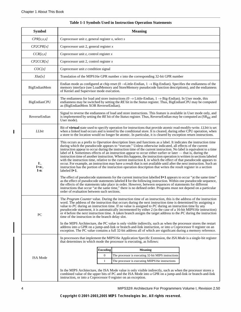
In this book, algorithmic descriptions of an operation are described as pseudocode in a high-level language notationresembling Pascal. Special symbols used in the pseudocode notation are listed in Table 1-1.
Table 1-1 Symbols Used in Instruction Operation Statements
Symbol Meaning
← Assignment
=, ≠ Tests for equality and inequality
|| Bit string concatenation
xy A y-bit string formed by y copies of the single-bit value x
b#nA constant value n in base b. For instance 10#100 represents the decimal value 100, 2#100 represents the binaryvalue 100 (decimal 4), and 16#100 represents the hexadecimal value 100 (decimal 256). If the "b#" prefix isomitted, the default base is 10.
0bn A constant value n in base 2. For instance 0b100 represents the binary value 100 (decimal 4).
0xn A constant value n in base 16. For instance 0x100 represents the hexadecimal value 100 (decimal 256).
xy..zSelection of bits y through z of bit string x. Little-endian bit notation (rightmost bit is 0) is used. If y is less thanz, this expression is an empty (zero length) bit string.
+, − 2’s complement or floating point arithmetic: addition, subtraction
∗, × 2’s complement or floating point multiplication (both used for either)
div 2’s complement integer division
mod 2’s complement modulo
/ Floating point division
< 2’s complement less-than comparison
> 2’s complement greater-than comparison
≤ 2’s complement less-than or equal comparison
≥ 2’s complement greater-than or equal comparison
nor Bitwise logical NOR
xor Bitwise logical XOR
and Bitwise logical AND
or Bitwise logical OR
GPRLEN The length in bits (32 or 64) of the CPU general-purpose registers
GPR[x] CPU general-purpose register x. The content of GPR[0] is always zero. In Release 2 of the Architecture, GPR[x]is a short-hand notation for SGPR[ SRSCtlCSS, x].
SGPR[s,x] In Release 2 of the Architecture, multiple copies of the CPU general-purpose registers may be implemented.SGPR[s,x] refers to GPR set s, register x.
FPR[x] Floating Point operand register x
FCC[CC] Floating Point condition code CC. FCC[0] has the same value as COC[1].
FPR[x] Floating Point (Coprocessor unit 1), general register x
4 MIPS32® Architecture For Programmers Volume I, Revision 2.50
Copyright © 2001-2003,2005 MIPS Technologies Inc. All rights reserved.
Chapter 1 About This Book
CPR[z,x,s] Coprocessor unit z, general register x, select s
CP2CPR[x] Coprocessor unit 2, general register x
CCR[z,x] Coprocessor unit z, control register x
CP2CCR[x] Coprocessor unit 2, control register x
COC[z] Coprocessor unit z condition signal
Xlat[x] Translation of the MIPS16e GPR number x into the corresponding 32-bit GPR number
BigEndianMemEndian mode as configured at chip reset (0 →Little-Endian, 1 → Big-Endian). Specifies the endianness of thememory interface (see LoadMemory and StoreMemory pseudocode function descriptions), and the endiannessof Kernel and Supervisor mode execution.
BigEndianCPUThe endianness for load and store instructions (0 → Little-Endian, 1 → Big-Endian). In User mode, thisendianness may be switched by setting the RE bit in the Status register. Thus, BigEndianCPU may be computedas (BigEndianMem XOR ReverseEndian).
ReverseEndianSignal to reverse the endianness of load and store instructions. This feature is available in User mode only, andis implemented by setting the RE bit of the Status register. Thus, ReverseEndian may be computed as (SRRE andUser mode).
LLbitBit of virtual state used to specify operation for instructions that provide atomic read-modify-write. LLbit is setwhen a linked load occurs and is tested by the conditional store. It is cleared, during other CPU operation, whena store to the location would no longer be atomic. In particular, it is cleared by exception return instructions.
I:,I+n:,I-n:
This occurs as a prefix to Operation description lines and functions as a label. It indicates the instruction timeduring which the pseudocode appears to “execute.” Unless otherwise indicated, all effects of the currentinstruction appear to occur during the instruction time of the current instruction. No label is equivalent to a timelabel of I. Sometimes effects of an instruction appear to occur either earlier or later — that is, during theinstruction time of another instruction. When this happens, the instruction operation is written in sections labeledwith the instruction time, relative to the current instruction I, in which the effect of that pseudocode appears tooccur. For example, an instruction may have a result that is not available until after the next instruction. Such aninstruction has the portion of the instruction operation description that writes the result register in a sectionlabeled I+1.
The effect of pseudocode statements for the current instruction labelled I+1 appears to occur “at the same time”as the effect of pseudocode statements labeled I for the following instruction. Within one pseudocode sequence,the effects of the statements take place in order. However, between sequences of statements for differentinstructions that occur “at the same time,” there is no defined order. Programs must not depend on a particularorder of evaluation between such sections.
PC
The Program Counter value. During the instruction time of an instruction, this is the address of the instructionword. The address of the instruction that occurs during the next instruction time is determined by assigning avalue to PC during an instruction time. If no value is assigned to PC during an instruction time by anypseudocode statement, it is automatically incremented by either 2 (in the case of a 16-bit MIPS16e instruction)or 4 before the next instruction time. A taken branch assigns the target address to the PC during the instructiontime of the instruction in the branch delay slot.
In the MIPS Architecture, the PC value is only visible indirectly, such as when the processor stores the restartaddress into a GPR on a jump-and-link or branch-and-link instruction, or into a Coprocessor 0 register on anexception. The PC value contains a full 32-bit address all of which are significant during a memory reference.
ISA Mode
In processors that implement the MIPS16e Application Specific Extension, the ISA Mode is a single-bit registerthat determines in which mode the processor is executing, as follows:
In the MIPS Architecture, the ISA Mode value is only visible indirectly, such as when the processor stores acombined value of the upper bits of PC and the ISA Mode into a GPR on a jump-and-link or branch-and-linkinstruction, or into a Coprocessor 0 register on an exception.
Table 1-1 Symbols Used in Instruction Operation Statements
Symbol Meaning
Encoding Meaning
0 The processor is executing 32-bit MIPS instructions
1 The processor is executing MIIPS16e instructions

1.4 For More Information
MIPS32® Architecture For Programmers Volume I, Revision 2.50 5
Copyright © 2001-2003,2005 MIPS Technologies Inc. All rights reserved.
1.4 For More Information
Various MIPS RISC processor manuals and additional information about MIPS products can be found at the MIPS URL:
http://www.mips.com
Comments or questions on the MIPS32® Architecture or this document should be directed to
MIPS Architecture GroupMIPS Technologies, Inc.1225 Charleston RoadMountain View, CA 94043
or via E-mail to [email protected].
PABITS The number of physical address bits implemented is represented by the symbol PABITS. As such, if 36 physicaladdress bits were implemented, the size of the physical address space would be 2PABITS = 236 bytes.
FP32RegistersMode
Indicates whether the FPU has 32-bit or 64-bit floating point registers (FPRs). In MIPS32, the FPU has 32 32-bitFPRs in which 64-bit data types are stored in even-odd pairs of FPRs. In MIPS64, the FPU has 32 64-bit FPRsin which 64-bit data types are stored in any FPR.
In MIPS32 implementations, FP32RegistersMode is always a 0. MIPS64 implementations have a compatibilitymode in which the processor references the FPRs as if it were a MIPS32 implementation. In such a caseFP32RegisterMode is computed from the FR bit in the Status register. If this bit is a 0, the processor operatesas if it had 32 32-bit FPRs. If this bit is a 1, the processor operates with 32 64-bit FPRs.
The value of FP32RegistersMode is computed from the FR bit in the Status register.
InstructionInBranchDelaySlot
Indicates whether the instruction at the Program Counter address was executed in the delay slot of a branch orjump. This condition reflects the dynamic state of the instruction, not the static state. That is, the value is falseif a branch or jump occurs to an instruction whose PC immediately follows a branch or jump, but which is notexecuted in the delay slot of a branch or jump.
SignalException(exception, argument)
Causes an exception to be signaled, using the exception parameter as the type of exception and the argumentparameter as an exception-specific argument). Control does not return from this pseudocode function - theexception is signaled at the point of the call.
Table 1-1 Symbols Used in Instruction Operation Statements
Symbol Meaning

6 MIPS32® Architecture For Programmers Volume I, Revision 2.50
Copyright © 2001-2003,2005 MIPS Technologies Inc. All rights reserved.
Chapter 1 About This Book

MIPS32® Architecture For Programmers Volume I, Revision 2.50 7
Copyright © 2001-2003,2005 MIPS Technologies Inc. All rights reserved.
Chapter 2
The MIPS Architecture: An Introduction
2.1 MIPS32 and MIPS64 Overview
2.1.1 Historical Perspective
The MIPS® Instruction Set Architecture (ISA) has evolved over time from the original MIPS I™ ISA, through the MIPSV™ ISA, to the current MIPS32® and MIPS64® Architectures. As the ISA evolved, all extensions have been backwardcompatible with previous versions of the ISA. In the MIPS III™ level of the ISA, 64-bit integers and addresses wereadded to the instruction set. The MIPS IV™ and MIPS V™ levels of the ISA added improved floating point operations,as well as a set of instructions intended to improve the efficiency of generated code and of data movement. Because ofthe strict backward-compatible requirement of the ISA, such changes were unavailable to 32-bit implementations of theISA which were, by definition, MIPS I™ or MIPS II™ implementations.
While the user-mode ISA was always backward compatible, the privileged environment was allowed to change on aper-implementation basis. As a result, the R3000® privileged environment was different from the R4000® privilegedenvironment, and subsequent implementations, while similar to the R4000 privileged environment, included subtledifferences. Because the privileged environment was never part of the MIPS ISA, an implementation had the flexibilityto make changes to suit that particular implementation. Unfortunately, this required kernel software changes to everyoperating system or kernel environment on which that implementation was intended to run.
Many of the original MIPS implementations were targeted at computer-like applications such as workstations andservers. In recent years MIPS implementations have had significant success in embedded applications. Today, most ofthe MIPS parts that are shipped go into some sort of embedded application. Such applications tend to have differenttrade-offs than computer-like applications including a focus on cost of implementation, and performance as a functionof cost and power.
The MIPS32 and MIPS64 Architectures are intended to address the need for a high-performance but cost-sensitive MIPSinstruction set. The MIPS32 Architecture is based on the MIPS II ISA, adding selected instructions from MIPS III, MIPSIV, and MIPS V to improve the efficiency of generated code and of data movement. The MIPS64 Architecture is basedon the MIPS V ISA and is backward compatible with the MIPS32 Architecture. Both the MIPS32 and MIPS64Architectures bring the privileged environment into the Architecture definition to address the needs of operating systemsand other kernel software. Both also include provision for adding MIPS Application Specific Extensions (ASEs), UserDefined Instructions (UDIs), and custom coprocessors to address the specific needs of particular markets.
MIPS32 and MIPS64 Architectures provides a substantial cost/performance advantage over microprocessorimplementations based on traditional architectures. This advantage is a result of improvements made in severalcontiguous disciplines: VLSI process technology, CPU organization, system-level architecture, and operating systemand compiler design.
2.1.2 Architectural Evolution
The evolution of an architecture is a dynamic process that takes into account both the need to provide a stable platformfor implementations, as well as new market and application areas that demand new capabilities. Enhancements to anarchitecture are appropriate when they:
• are applicable to a wide market
• provide long-term benefit

8 MIPS32® Architecture For Programmers Volume I, Revision 2.50
Copyright © 2001-2003,2005 MIPS Technologies Inc. All rights reserved.
Chapter 2 The MIPS Architecture: An Introduction
• maintain architectural scalability
• are standardized to prevent fragmentation
• are a superset of the existing architecture
The MIPS Architecture community constantly evaluates suggestions for architectural changes and enhancements againstthese criteria. New releases of the architecture, while infrequent, are made at appropriate points, following these criteria.At present, there are two releases of the MIPS Architecture: Release 1 (the original version of the MIPS32 Architecture)and Release 2 which was added in 2002.
2.1.2.1 Release 2 of the MIPS32 Architecture
Enhancements included in Release 2 of the MIPS32 Architecture are:
• Vectored interrupts: This enhancement provides the ability to vector interrupts directly to a handler for that interrupt.Vectored interrupts are an option in Release 2 implementations and the presence of that option is denoted by theConfig3VInt bit.
• Support for an external interrupt controller: This enhancement reconfigures the on-core interrupt logic to take fulladvantage of an external interrupt controller. This support is an option in Release 2 implementations and the presenceof that option is denoted by the Config3EIC bit.
• Programmable exception vector base: This enhancement allows the base address of the exception vectors to bemoved for exceptions that occur when StatusBEV is 0. Doing so allows multi-processor systems to have separateexception vectors for each processor, and allows any system to place the exception vectors in memory that isappropriate to the system environment. This enhancement is required in a Release 2 implementation.
• Atomic interrupt enable/disable: Two instructions have been added to atomically enable or disable interrupts, andreturn the previous value of the Status register. These instructions are required in a Release 2 implementation.
• The ability to disable the Count register for highly power-sensitive applications. This enhancement is required in aRelease 2 implementation.
• GPR shadow registers: This addition provides the addition of GPR shadow registers and the ability to bind theseregisters to a vectored interrupt or exception. Shadow registers are an option in Release 2 implementations and thepresence of that option is denoted by a non-zero value in SRSCtlHSS. While shadow registers are most useful wheneither vectored interrupts or support for an external interrupt controller is also implemented, neither is required.
• Field, Rotate and Shuffle instructions: These instructions add additional capability in processing bit fields inregisters. These instructions are required in a Release 2 implementation.
• Explicit hazard management: This enhancement provides a set of instructions to explicitly manage hazards, in placeof the cycle-based SSNOP method of dealing with hazards. These instructions are required in a Release 2implementation.
• Access to a new class of hardware registers and state from an unprivileged mode. This enhancement is required in aRelease 2 implementation.
• Coprocessor 0 Register changes: These changes add or modify CP0 registers to indicate the existence of new andoptional state, provide L2 and L3 cache identification, add trigger bits to the Watch registers, and add support for64-bit performance counter count registers. This enhancement is required in a Release 2 implementation.
• Support for 64-bit coprocessors with 32-bit CPUs: These changes allow a 64-bit coprocessor (including an FPU) tobe attached to a 32-bit CPU. This enhancement is optional in a Release 2 implementation.
• New Support for Virtual Memory: These changes provide support for a 1KByte page size. This change is optional inRelease 2 implementations, and support is denoted by Config3SP.

2.2 Compliance and Subsetting
MIPS32® Architecture For Programmers Volume I, Revision 2.50 9
Copyright © 2001-2003,2005 MIPS Technologies Inc. All rights reserved.
2.1.3 Architectural Changes Relative to the MIPS I through MIPS V Architectures
In addition to the MIPS32 Architecture described in this document set, the following changes were made to thearchitecture relative to the earlier MIPS RISC Architecture Specification, which describes the MIPS I through MIPS VArchitectures.
• The MIPS IV ISA added a restriction to the load and store instructions which have natural alignment requirements(all but load and store byte and load and store left and right) in which the base register used by the instruction mustalso be naturally aligned (the restriction expressed in the MIPS RISC Architecture Specification is that the offset bealigned, but the implication is that the base register is also aligned, and this is more consistent with the indexedload/store instructions which have no offset field). The restriction that the base register be naturally-aligned iseliminated by the MIPS32 Architecture, leaving the restriction that the effective address be naturally-aligned.
• Early MIPS implementations required two instructions separating a mflo or mfhi from the next integer multiply ordivide operation. This hazard was eliminated in the MIPS IV ISA, although the MIPS RISC ArchitectureSpecification does not clearly explain this fact. The MIPS32 Architecture explicitly eliminates this hazard andrequires that the hi and lo registers be fully interlocked in hardware for all integer multiply and divide instructions(including, but not limited to, the madd, maddu, msub, msubu, and mul instructions introduced in this specification).
• The Implementation and Programming Notes included in the instruction descriptions for the madd, maddu, msub,msubu, and mul instructions should also be applied to all integer multiply and divide instructions in the MIPS RISCArchitecture Specification.
2.2 Compliance and Subsetting
To be compliant with the MIPS32 Architecture, designs must implement a set of required features, as described in thisdocument set. To allow flexibility in implementations, the MIPS32 Architecture does provide subsetting rules. Animplementation that follows these rules is compliant with the MIPS32 Architecture as long as it adheres strictly to therules, and fully implements the remaining instructions.Supersetting of the MIPS32 Architecture is only allowed byadding functions to the SPECIAL2 major opcode, by adding control for co-processors via the COP2, LWC2, SWC2,LDC2, and/or SDC2, and/or COP3 opcodes, or via the addition of approved Application Specific Extensions. Note,however, that a decision to use the COP3 opcode in an implementation of the MIPS32 Architecture precludes acompatible upgrade to the MIPS64 Architecture because the COP3 opcode is used as part of the floating point ISA inthe MIPS64 Architecture.
The instruction set subsetting rules are as follows:
• All CPU instructions must be implemented - no subsetting is allowed.
• The FPU and related support instructions, including the MOVF and MOVT CPU instructions, may be omitted.Software may determine if an FPU is implemented by checking the state of the FP bit in the Config1 CP0 register. Ifthe FPU is implemented, it must include S, D, and W formats, operate instructions, and all supporting instructions.Software may determine which FPU data types are implemented by checking the appropriate bit in the FIR CP1register. The following allowable FPU subsets are compliant with the MIPS32 architecture:
– No FPU
– FPU with S, D, and W formats and all supporting instructions
• Coprocessor 2 is optional and may be omitted. Software may determine if Coprocessor 2 is implemented by checkingthe state of the C2 bit in the Config1 CP0 register. If Coprocessor 2 is implemented, the Coprocessor 2 interfaceinstructions (BC2, CFC2, COP2, CTC2, LDC2, LWC2, MFC2, MTC2, SDC2, and SWC2) may be omitted on aninstruction-by-instruction basis.
• Supervisor Mode is optional. If Supervisor Mode is not implemented, bit 3 of the Status register must be ignored onwrite and read as zero.
• The standard TLB-based memory management unit may be replaced with a simpler MMU (e.g., a Fixed MappingMMU). If this is done, the rest of the interface to the Privileged Resource Architecture must be preserved. If a

10 MIPS32® Architecture For Programmers Volume I, Revision 2.50
Copyright © 2001-2003,2005 MIPS Technologies Inc. All rights reserved.
Chapter 2 The MIPS Architecture: An Introduction
TLB-based memory management unit is implemented, it must be the standard TLB-based MMU as described in thePrivileged Resource Architecture chapter. Software may determine the type of the MMU by checking the MT field inthe Config CP0 register.
• The Privileged Resource Architecture includes several implementation options and may be subsetted in accordancewith those options.
• Instruction, CP0 Register, and CP1 Control Register fields that are marked “Reserved” or shown as “0” in thedescription of that field are reserved for future use by the architecture and are not available to implementations.Implementations may only use those fields that are explicitly reserved for implementation dependent use.
• Supported ASEs are optional and may be subsetted out. If most cases, software may determine if a supported ASE isimplemented by checking the appropriate bit in the Config1 or Config3 CP0 register. If they are implemented, theymust implement the entire ISA applicable to the component, or implement subsets that are approved by the ASEspecifications.
• EJTAG is optional and may be subsetted out. If it is implemented, it must implement only those subsets that areapproved by the EJTAG specification.
• If any instruction is subsetted out based on the rules above, an attempt to execute that instruction must cause theappropriate exception (typically Reserved Instruction or Coprocessor Unusable).
2.3 Components of the MIPS Architecture
2.3.1 MIPS Instruction Set Architecture (ISA)
The MIPS32 and MIPS64 Instruction Set Architectures define a compatible family of 32-bit and 64-bit instructionswithin the framework of the overall MIPS32 and MIPS64 Architectures. Included in the ISA are all instructions, bothprivileged and unprivileged, by which the programmer interfaces with the processor. The ISA guarantees object codecompatibility for unprivileged and, often, privileged programs executing on any MIPS32 or MIPS64 processor; allinstructions in the MIPS64 ISA are backward compatible with those instructions in the MIPS32 ISA. Using conditionalcompilation or assembly language macros, it is often possible to write privileged programs that run on both MIPS32 andMIPS64 implementations.
2.3.2 MIPS Privileged Resource Architecture (PRA)
The MIPS32 and MIPS64 Privileged Resource Architecture defines a set of environments and capabilities on which theISA operates. The effects of some components of the PRA are visible to unprivileged programs; for instance, the virtualmemory layout. Many other components are visible only to privileged programs and the operating system. The PRAprovides the mechanisms necessary to manage the resources of the processor: virtual memory, caches, exceptions, usercontexts, etc.
2.3.3 MIPS Application Specific Extensions (ASEs)
The MIPS32 and MIPS64 Architectures provide support for optional application specific extensions. As optionalextensions to the base architecture, the ASEs do not burden every implementation of the architecture with instructionsor capability that are not needed in a particular market. An ASE can be used with the appropriate ISA and PRA to meetthe needs of a specific application or an entire class of applications.

2.4 Architecture Versus Implementation
MIPS32® Architecture For Programmers Volume I, Revision 2.50 11
Copyright © 2001-2003,2005 MIPS Technologies Inc. All rights reserved.
2.3.4 MIPS User Defined Instructions (UDIs)
In addition to support for ASEs as described above, the MIPS32 and MIPS64 Architectures define specific instructionsfor the use of each implementation. The Special2 instruction function fields and Coprocessor 2 are reserved forcapability defined by each implementation.
2.4 Architecture Versus Implementation
When describing the characteristics of MIPS processors, architecture must be distinguished from the hardwareimplementation of that architecture.
• Architecture refers to the instruction set, registers and other state, the exception model, memory management,virtual and physical address layout, and other features that all hardware executes.
• Implementation refers to the way in which specific processors apply the architecture.
Here are two examples:
1. A floating point unit (FPU) is an optional part of the MIPS32 Architecture. A compatible implementation of theFPU may have different pipeline lengths, different hardware algorithms for performing multiplication or division,etc.
2. Most MIPS processors have caches; however, these caches are not implemented in the same manner in all MIPSprocessors. Some processors implement physically-indexed, physically tagged caches. Other implementvirtually-indexed, physically-tagged caches. Still other processor implement more than one level of cache.
The MIPS32 architecture is decoupled from specific hardware implementations, leaving microprocessor designers freeto create their own hardware designs within the framework of the architectural definition.
2.5 Relationship between the MIPS32 and MIPS64 Architectures
The MIPS Architecture evolved as a compromise between software and hardware resources. The architectureguarantees object-code compatibility for User-Mode programs executed on any MIPS processor. In User Mode MIPS64processors are backward-compatible with their MIPS32 predecessors. As such, the MIPS32 Architecture is a strictsubset of the MIPS64 Architecture. The relationship between the architectures is shown in Figure 2-1.
Figure 2-1 Relationship between the MIPS32 and MIPS64 Architectures
MIPS32Architecture
MIPS64Architecture
High-performance 32-bitInstruction Set Architecture andPrivileged ResourceArchitecture
High-performance 64-bitInstruction Set Architecture andPrivileged ResourceArchitecture, fully backwardcompatible with the 32-bitarchitecture

12 MIPS32® Architecture For Programmers Volume I, Revision 2.50
Copyright © 2001-2003,2005 MIPS Technologies Inc. All rights reserved.
Chapter 2 The MIPS Architecture: An Introduction
2.6 Instructions, Sorted by ISA
This section lists the instructions that are a part of the MIPS32 and MIPS64 ISAs.
2.6.1 List of MIPS32 Instructions
Table 2-1 lists of those instructions included in the MIPS32 ISA.
Table 2-1 MIPS32 Instructions
ABS.D ABS.PS1
1. In Release 1 of the Architecture, these instructions are legal only with a MIPS64 processor with 64-bit operations enabled (they are, in effect,actually MIPS64 instructions). In Release 2 of the Architecture, these instructions are legal with either a MIPS32 or MIPS64 processorwhich includes a 64-bit floating point unit.
ABS.S ADD ADD.D ADD.PS1 ADD.S ADDI
ADDIU ADDU ALNV.PS1 AND ANDI BC1F BC1FL BC1T
BC1TL BC2F BC2FL BC2T BC2TL BEQ BEQL BGEZ
BGEZAL BGEZALL BGEZL BGTZ BGTZL BLEZ BLEZL BLTZ
BLTZAL BLTZALL BLTZL BNE BNEL BREAK C.cond.D C.cond.PS1
C.cond.S CACHE CEIL.L.D1 CEIL.L.S1 CEIL.W.D CEIL.W.S CFC1 CFC2
CLO CLZ COP2 CTC1 CTC2 CVT.D.L1 CVT.D.S CVT.D.W
CVT.L.D1 CVT.L.S1 CVT.PS.S1 CVT.S.D CVT.S.L1 CVT.S.PL1 CVT.S.PU1 CVT.S.W
CVT.W.D CVT.W.S DERET DI2
2. These instructions are legal only in an implementation of Release 2 of the Architecture
DIV DIV.D DIV.S DIVU
EHB2 EI2 ERET EXT2 FLOOR.L.D1 FLOOR.L.S1 FLOOR.W.D FLOOR.W.S
INS2 J JAL JALR JALR.HB2 JR JR.HB2 LB
LBU LDC1 LDC2 LDXC11 LH LHU LL LUI
LUXC11 LW LWC1 LWC2 LWL LWR LWXC11 MADD
MADD.D1 MADD.PS1 MADD.S1 MADDU MFC0 MFC1 MFC2 MFHC12
MFHC22 MFHI MFLO MOV.D MOV.PS1 MOV.S MOVF MOVF.D
MOVF.PS1 MOVF.S MOVN MOVN.D MOVN.PS1 MOVN.S MOVT MOVT.D
MOVT.PS1 MOVT.S MOVZ MOVZ.D MOVZ.PS1 MOVZ.S MSUB MSUB.D1
MSUB.PS1 MSUB.S1 MSUBU MTC0 MTC1 MTC2 MTHC12 MTHC22
MTHI MTLO MUL MUL.D MUL.PS1 MUL.S MULT MULTU
NEG.D NEG.PS1 NEG.S NMADD.D1 NMADD.PS1 NMADD.S1 NMSUB.D1 NMSUB.PS1
NMSUB.S1 NOR OR ORI PLL.PS1 PLU.PS1 PREF PREFX1
PUL.PS1 PUU.PS1 RDHWR2 RDPGPR2 RECIP.D1 RECIP.S1 ROTR2 ROTRV2
ROUND.L.D1 ROUND.L.S1 ROUND.W.D ROUND.W.S RSQRT.D1 RSQRT.S1 SB SC
SDBBP SDC1 SDC2 SDXC11 SEB2 SEH2 SH SLL
SLLV SLT SLTI SLTIU SLTU SQRT.D SQRT.S SRA
SRAV SRL SRLV SSNOP SUB SUB.D SUB.PS1 SUB.S
SUBU SUXC11 SW SWC1 SWC2 SWL SWR SWXC11
SYNC SYNCI2 SYSCALL TEQ TEQI TGE TGEI TGEIU
TGEU TLBP TLBR TLBWI TLBWR TLT TLTI TLTIU
TLTU TNE TNEI TRUNC.L.D1 TRUNC.L.S1 TRUNC.W.D TRUNC.W.S WAIT
WRPGPR2 WSBH2 XOR XORI

2.7 Pipeline Architecture
MIPS32® Architecture For Programmers Volume I, Revision 2.50 13
Copyright © 2001-2003,2005 MIPS Technologies Inc. All rights reserved.
2.6.2 List of MIPS64 Instructions
Table 2-2 lists of those instructions introduced in the MIPS64 ISA.
Table 2-2 MIPS64 Instructions
2.7 Pipeline Architecture
This section describes the basic pipeline architecture, along with two types of improvements: superpipelines andsuperscalar pipelines. (Pipelining and multiple issuing are not defined by the ISA, but are implementation dependent.)
2.7.1 Pipeline Stages and Execution Rates
MIPS processors all use some variation of a pipeline in their architecture. A pipeline is divided into the following discreteparts, or stages, shown in Figure 2-2:
• Fetch
• Arithmetic operation
• Memory access
• Write back
Figure 2-2 One-Deep Single-Completion Instruction Pipeline
In the example shown in Figure 2-2, each stage takes one processor clock cycle to complete. Thus it takes four clockcycles (ignoring delays or stalls) for the instruction to complete. In this example, the execution rate of the pipeline isone instruction every four clock cycles. Conversely, because only a single execution can be fetched before completion,only one stage is active at any time.
DADD DADDI DADDIU DADDU DCLO DDIV DDIVU DEXT1
1. These instructions are legal only in an implementation of Release 2 of the Architecture
DEXTM1 DEXTU1 DINS1 DINSM1 DINSU1 DLCZ DMFC0 DMFC1
DMFC2 DMTC0 DMTC1 DMTC2 DMULT DMULTU DROTR1 DROTR321
DROTRV1 DSBH1 DSHD1 DSLL DSLL32 DSLLV DSRA DSRA32
DSRAV DSRL DSRL32 DSRLV DSUB DSUBU LD LDL
LDR LLD LWU SCD SD SDL SDR
Instruction 1
Fetch ALU Memory Write
Cycle 1 Cycle 2 Cycle 3 Cycle 4
Stage 1 Stage 2 Stage 3 Stage 4
Execution Rate
Cycle 5 Cycle 6 Cycle 7 Cycle 8
Cycle 3
Instruction 2
Stage 1 Stage 2 Stage 3 Stage 4
Fetch ALU Memory WriteInstruction completion

14 MIPS32® Architecture For Programmers Volume I, Revision 2.50
Copyright © 2001-2003,2005 MIPS Technologies Inc. All rights reserved.
Chapter 2 The MIPS Architecture: An Introduction
2.7.2 Parallel Pipeline
Figure 2-3 illustrates a remedy for the latency (the time it takes to execute an instruction) inherent in the pipeline shownin Figure 2-2.
Instead of waiting for an instruction to be completed before the next instruction can be fetched (four clock cycles), a newinstruction is fetched each clock cycle. There are four stages to the pipeline so the four instructions can be executedsimultaneously, one at each stage of the pipeline. It still takes four clock cycles for the first instruction to be completed;however, in this theoretical example, a new instruction is completed every clock cycle thereafter. Instructions in Figure2-3 are executed at a rate four times that of the pipeline shown in Figure 2-2.
Figure 2-3 Four-Deep Single-Completion Pipeline
2.7.3 Superpipeline
Figure 2-4 shows a superpipelined architecture. Each stage is designed to take only a fraction of an external clockcycle—in this case, half a clock. Effectively, each stage is divided into more than one substage. Therefore more thanone instruction can be completed each cycle.
Figure 2-4 Four-Deep Superpipeline
2.7.4 Superscalar Pipeline
A superscalar architecture also allows more than one instruction to be completed each clock cycle. Figure 2-5 shows afour-way, five-stage superscalar pipeline.
Cycle 1
Instruction 1
Cycle 2 Cycle 3 Cycle 4 Cycle 5 Cycle 6 Cycle 7
Instruction 2
Instruction 3
Instruction 4
Fetch ALU Memory Write
Fetch ALU Memory Write
Fetch ALU Memory Write
Fetch ALU Memory Write
Clock
Phase
Cycle 1 Cycle 2 Cycle 3 Cycle 4 Cycle 5 Cycle 6 Cycle 7 Cycle 8
1 2 1 2 1 2 1 2 1 2 1 2 1 2 1 2
Fetch ALU Mem Write
Fetch ALU Mem Write
Fetch ALU Mem Write
Fetch ALU Mem Write
Fetch ALU Mem Write
Fetch ALU Mem Write
Fetch ALU Mem Write
Fetch ALU Mem Write

2.8 Load/Store Architecture
MIPS32® Architecture For Programmers Volume I, Revision 2.50 15
Copyright © 2001-2003,2005 MIPS Technologies Inc. All rights reserved.
Figure 2-5 Four-Way Superscalar Pipeline
2.8 Load/Store Architecture
Generally, it takes longer to perform operations in memory than it does to perform them in on-chip registers. This isbecause of the difference in time it takes to access a register (fast) and main memory (slower).
To eliminate the longer access time, or latency, of in-memory operations, MIPS processors use a load/store design. Theprocessor has many registers on chip, and all operations are performed on operands held in these processor registers.Main memory is accessed only through load and store instructions. This has several benefits:
• Reducing the number of memory accesses, easing memory bandwidth requirements
• Simplifying the instruction set
• Making it easier for compilers to optimize register allocation
2.9 Programming Model
This section describes the following aspects of the programming model:
• “CPU Data Formats”
• “Coprocessors (CP0-CP3)”
• “CPU Registers”
• “FPU Data Formats”
• “Byte Ordering and Endianness”
• “Memory Access Types”
Instruction 1
Instruction 2
Instruction 3
Instruction 4
Instruction 5
Instruction 6
Instruction 7
Instruction 8
Five-stage
Four-way
IF = instruction fetchID = instruction decode and dependencyIS = instruction issueEX = executionWB = write back
IF ID IS EX WB
IF ID IS EX WB
IF ID IS EX WB
IF ID IS EX WB
IF ID IS EX WB
IF ID IS EX WB
IF ID IS EX WB
IF ID IS EX WB

16 MIPS32® Architecture For Programmers Volume I, Revision 2.50
Copyright © 2001-2003,2005 MIPS Technologies Inc. All rights reserved.
Chapter 2 The MIPS Architecture: An Introduction
2.9.1 CPU Data Formats
The CPU defines the following data formats:
• Bit (b)
• Byte (8 bits, B)
• Halfword (16 bits, H)
• Word (32 bits, W)
• Doubleword (64 bits, D)1
2.9.2 FPU Data Formats
The FPU defines the following data formats:
• 32-bit single-precision floating point (.fmt type S)
• 32-bit single-precision floating point paired-single (.fmt type PS)1
• 64-bit double-precision floating point (.fmt type D)
• 32-bit Word fixed point (.fmt type W)
• 64-bit Long fixed point (.fmt type L)1
2.9.3 Coprocessors (CP0-CP3)
The MIPS Architecture defines four coprocessors (designated CP0, CP1, CP2, and CP3):
• Coprocessor 0 (CP0) is incorporated on the CPU chip and supports the virtual memory system and exceptionhandling. CP0 is also referred to as the System Control Coprocessor.
• Coprocessor 1 (CP1) is reserved for the floating point coprocessor, the FPU.
• Coprocessor 2 (CP2) is available for specific implementations.
• Coprocessor 3 (CP3) is reserved for the floating point unit in a Release 1 implementation of the MIPS64Architecture, and on all Release 2 implementations of the Architecture.
CP0 translates virtual addresses into physical addresses, manages exceptions, and handles switches between kernel,supervisor, and user states. CP0 also controls the cache subsystem, as well as providing diagnostic control and errorrecovery facilities. The architectural features of CP0 are defined in Volume III.
2.9.4 CPU Registers
The MIPS32 Architecture defines the following CPU registers:
• 32 32-bit general purpose registers (GPRs)
• a pair of special-purpose registers to hold the results of integer multiply, divide, and multiply-accumulate operations(HI and LO)
1 The CPU Doubleword and FPU floating point paired-single and Long fixed point data formats are available in a Release 1implementation of the MIPS64 Architecture, or in a Release 2 implementation either the MIPS32 or MIPS64 Architecture that includesa 64-bit floating point unit
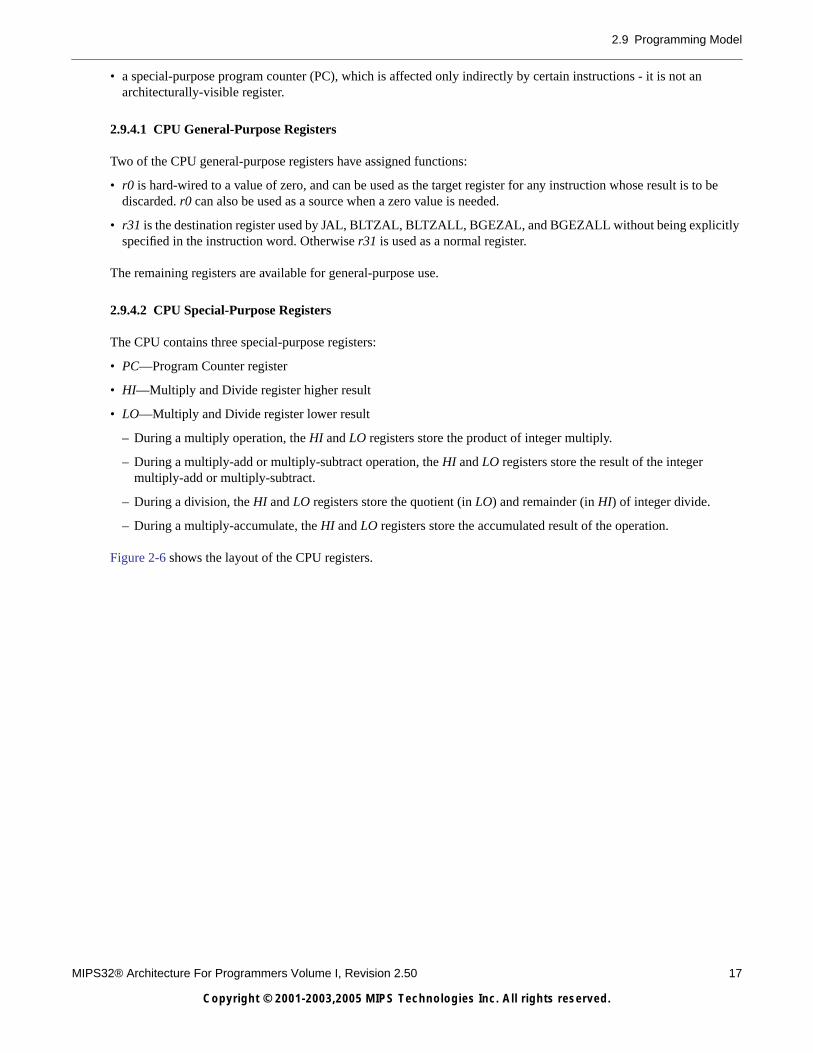
2.9 Programming Model
MIPS32® Architecture For Programmers Volume I, Revision 2.50 17
Copyright © 2001-2003,2005 MIPS Technologies Inc. All rights reserved.
• a special-purpose program counter (PC), which is affected only indirectly by certain instructions - it is not anarchitecturally-visible register.
2.9.4.1 CPU General-Purpose Registers
Two of the CPU general-purpose registers have assigned functions:
• r0 is hard-wired to a value of zero, and can be used as the target register for any instruction whose result is to bediscarded. r0 can also be used as a source when a zero value is needed.
• r31 is the destination register used by JAL, BLTZAL, BLTZALL, BGEZAL, and BGEZALL without being explicitlyspecified in the instruction word. Otherwise r31 is used as a normal register.
The remaining registers are available for general-purpose use.
2.9.4.2 CPU Special-Purpose Registers
The CPU contains three special-purpose registers:
• PC—Program Counter register
• HI—Multiply and Divide register higher result
• LO—Multiply and Divide register lower result
– During a multiply operation, the HI and LO registers store the product of integer multiply.
– During a multiply-add or multiply-subtract operation, the HI and LO registers store the result of the integermultiply-add or multiply-subtract.
– During a division, the HI and LO registers store the quotient (in LO) and remainder (in HI) of integer divide.
– During a multiply-accumulate, the HI and LO registers store the accumulated result of the operation.
Figure 2-6 shows the layout of the CPU registers.

18 MIPS32® Architecture For Programmers Volume I, Revision 2.50
Copyright © 2001-2003,2005 MIPS Technologies Inc. All rights reserved.
Chapter 2 The MIPS Architecture: An Introduction
2.9.5 FPU Registers
The MIPS32 Architecture defines the following FPU registers:
• 32 floating point registers (FPRs). These registers are 32 bits wide in a 32-bit FPU and 64 bits wide on a 64-bit FPU.
• Five FPU control registers are used to identify and control the FPU.
• Eight floating point condition codes that are part of the FCSR register
Figure 2-6 CPU Registers
31 0 31 0
r0 (hardwired to zero) HI
r1 LO
r2
r3
r4
r5
r6
r7
r8
r9
r10
r11
r12
r13
r14
r15
r16
r17
r18
r19
r20
r21
r22
r23
r24
r25
r26
r27
r28
r29
r30 31 0
r31 PC
General Purpose Registers Special Purpose Registers
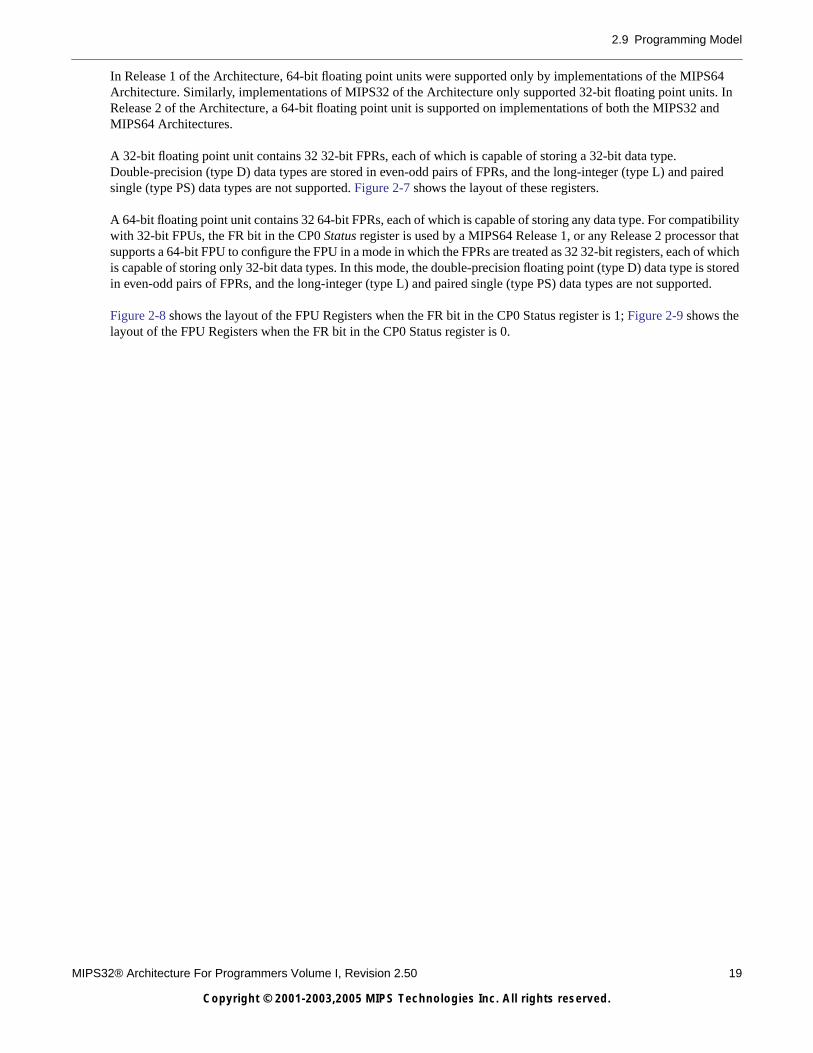
2.9 Programming Model
MIPS32® Architecture For Programmers Volume I, Revision 2.50 19
Copyright © 2001-2003,2005 MIPS Technologies Inc. All rights reserved.
In Release 1 of the Architecture, 64-bit floating point units were supported only by implementations of the MIPS64Architecture. Similarly, implementations of MIPS32 of the Architecture only supported 32-bit floating point units. InRelease 2 of the Architecture, a 64-bit floating point unit is supported on implementations of both the MIPS32 andMIPS64 Architectures.
A 32-bit floating point unit contains 32 32-bit FPRs, each of which is capable of storing a 32-bit data type.Double-precision (type D) data types are stored in even-odd pairs of FPRs, and the long-integer (type L) and pairedsingle (type PS) data types are not supported. Figure 2-7 shows the layout of these registers.
A 64-bit floating point unit contains 32 64-bit FPRs, each of which is capable of storing any data type. For compatibilitywith 32-bit FPUs, the FR bit in the CP0 Status register is used by a MIPS64 Release 1, or any Release 2 processor thatsupports a 64-bit FPU to configure the FPU in a mode in which the FPRs are treated as 32 32-bit registers, each of whichis capable of storing only 32-bit data types. In this mode, the double-precision floating point (type D) data type is storedin even-odd pairs of FPRs, and the long-integer (type L) and paired single (type PS) data types are not supported.
Figure 2-8 shows the layout of the FPU Registers when the FR bit in the CP0 Status register is 1; Figure 2-9 shows thelayout of the FPU Registers when the FR bit in the CP0 Status register is 0.

20 MIPS32® Architecture For Programmers Volume I, Revision 2.50
Copyright © 2001-2003,2005 MIPS Technologies Inc. All rights reserved.
Chapter 2 The MIPS Architecture: An Introduction
Figure 2-7 FPU Registers for a 32-bit FPU
31 0
f0
f1
f2
f3
f4
f5
f6
f7
f8
f9
f10
f11
f12
f13
f14
f15
f16
f17
f18
f19
f20
f21
f22
f23
f24
f25
f26 31 0
f27 FIR
f28 FCCR
f29 FEXR
f30 FENR
f31 FCSR
General Purpose Registers Special Purpose Registers

2.9 Programming Model
MIPS32® Architecture For Programmers Volume I, Revision 2.50 21
Copyright © 2001-2003,2005 MIPS Technologies Inc. All rights reserved.
2.9.6 Byte Ordering and EndiannessFigure 2-8 FPU Registers for a 64-bit FPU if StatusFR is 1
63 0
f0
f1
f2
f3
f4
f5
f6
f7
f8
f9
f10
f11
f12
f13
f14
f15
f16
f17
f18
f19
f20
f21
f22
f23
f24
f25
f26 31 0
f27 FIR
f28 FCCR
f29 FEXR
f30 FENR
f31 FCSR
General Purpose Registers Special Purpose Registers

22 MIPS32® Architecture For Programmers Volume I, Revision 2.50
Copyright © 2001-2003,2005 MIPS Technologies Inc. All rights reserved.
Chapter 2 The MIPS Architecture: An Introduction
Bytes within larger CPU data formats—halfword, word, and doubleword—can be configured in either big-endian orlittle-endian order, as described in the following subsections:
• “Big-Endian Order”
• “Little-Endian Order”
• “MIPS Bit Endianness”
Figure 2-9 FPU Registers for a 64-bit FPU if StatusFR is 0
63 32 31 0
UN
PR
ED
ICT
AB
LE
f0
f1
f2
f3
f4
f5
f6
f7
f8
f9
f10
f11
f12
f13
f14
f15
f16
f17
f18
f19
f20
f21
f22
f23
f24
f25
f26 31 0
f27 FCR0
f28 FCR25
f29 FCR26
f30 FCR28
f31 FCSR
General Purpose Registers Special Purpose Registers

2.9 Programming Model
MIPS32® Architecture For Programmers Volume I, Revision 2.50 23
Copyright © 2001-2003,2005 MIPS Technologies Inc. All rights reserved.
Endianness defines the location of byte 0 within a larger data structure (in this book, bits are always numbered with 0on the right). Figures 2-10 and 2-11 show the ordering of bytes within words and the ordering of words withinmultiple-word structures for both big-endian and little-endian configurations.
2.9.6.1 Big-Endian Order
When configured in big-endian order, byte 0 is the most-significant (left-hand) byte. Figure 2-10 shows thisconfiguration.
Figure 2-10 Big-Endian Byte Ordering
2.9.6.2 Little-Endian Order
When configured in little-endian order, byte 0 is always the least-significant (right-hand) byte. Figure 2-11 shows thisconfiguration.
Figure 2-11 Little-Endian Byte Ordering
2.9.6.3 MIPS Bit Endianness
In this book, bit 0 is always the least-significant (right-hand) bit. Although no instructions explicitly designate bitpositions within words, MIPS bit designations are always little-endian.
Figure 2-12 shows big-endian and Figure 2-13 shows little-endian byte ordering in doublewords.
Bit #HigherAddress
WordAddress
LowerAddress
12
8
4
0
12 13 14 15
111098
7654
3210 1 word = 4 bytes
31 24 23 16 15 8 7 0
Bit #HigherAddress
WordAddress
LowerAddress
12
8
4
0
15 14 13 12
891011
4567
0123
31 24 23 16 15 8 7 0

24 MIPS32® Architecture For Programmers Volume I, Revision 2.50
Copyright © 2001-2003,2005 MIPS Technologies Inc. All rights reserved.
Chapter 2 The MIPS Architecture: An Introduction
Figure 2-12 Big-Endian Data in Doubleword Format
Figure 2-13 Little-Endian Data in Doubleword Format
2.9.6.4 Addressing Alignment Constraints
The CPU uses byte addressing for halfword, word, and doubleword accesses with the following alignment constraints:
• Halfword accesses must be aligned on an even byte boundary (0, 2, 4...).
• Word accesses must be aligned on a byte boundary divisible by four (0, 4, 8...).
• Doubleword accesses must be aligned on a byte boundary divisible by eight (0, 8, 16...).
2.9.6.5 Unaligned Loads and Stores
The following instructions load and store words that are not aligned on word (W) or doubleword (D) boundaries:
Figure 2-14 show a big-endian access of a misaligned word that has byte address 3, and Figure 2-15 shows a little-endianaccess of a misaligned word that has byte address 1.1
Table 2-3 Unaligned Load and Store Instructions
Alignment Instructions Instruction Set
Word LWL, LWR, SWL, SWR MIPS32 ISA
Doubleword LDL, LDR, SDL, SDR MIPS64 ISA
Bit #
Halfword
Word
Byte #63 40
41556 55 48 47 3239
76516
327831 24 23
67
0
Byte
Most-significant byte Least-significant byte
Bits in a byte
Bit #
10
5 4 3 2 1 0
Bit #
Halfword
Word
Byte #63 40
31556 55 48 47 3239
01216
457831 24 23
67
7
Byte
Most-significant byte Least-significant byte
Bits in a byte
Bit #
60
5 4 3 2 1 0

2.9 Programming Model
MIPS32® Architecture For Programmers Volume I, Revision 2.50 25
Copyright © 2001-2003,2005 MIPS Technologies Inc. All rights reserved.
Figure 2-14 Big-Endian Misaligned Word Addressing
Figure 2-15 Little-Endian Misaligned Word Addressing
2.9.7 Memory Access Types
MIPS systems provide several memory access types. These are characteristic ways to use physical memory and cachesto perform a memory access.
The memory access type is identified by the cache coherence algorithm (CCA) bits in the TLB entry for each mappedvirtual page. The access type used for a location is associated with the virtual address, not the physical address or theinstruction making the reference. Memory access types are available for both uniprocessor and multiprocessor (MP)implementations.
All implementations must provide the following memory access types:
• Uncached
• Cached
These memory access types are described in the following sections:
• “Uncached Memory Access”
• “Cached Memory Access”
2.9.7.1 Uncached Memory Access
In an uncached access, physical memory resolves the access. Each reference causes a read or write to physical memory.Caches are neither examined nor modified.
1 These two figures show left-side misalignment.
Bit #Higher
Address
LowerAddress
823 16 15 731 0244 5 6
3
HigherAddress
LowerAddress
Bit #
823 16 15 731 0244
123

26 MIPS32® Architecture For Programmers Volume I, Revision 2.50
Copyright © 2001-2003,2005 MIPS Technologies Inc. All rights reserved.
Chapter 2 The MIPS Architecture: An Introduction
2.9.7.2 Cached Memory Access
In a cached access, physical memory and all caches in the system containing a copy of the physical location are used toresolve the access. A copy of a location is coherent if the copy was placed in the cache by a cached coherent access; acopy of a location is noncoherent if the copy was placed in the cache by a cached noncoherent access. (Coherency isdictated by the system architecture, not the processor implementation.)
Caches containing a coherent copy of the location are examined and/or modified to keep the contents of the locationcoherent. It is not possible to predict whether caches holding a noncoherent copy of the location will be examined and/ormodified during a cached coherent access.
2.9.8 Implementation-Specific Access Types
An implementation may provide memory access types other than uncached or cached. Implementation-specificdocumentation accompanies each processor, and defines the properties of the new access types and their effect on allmemory-related operations.
2.9.9 Cache Coherence Algorithms and Access Types
Memory access types are specified by architecturally-defined and implementation-specific cache coherence algorithmbits (CCAs) kept in TLB entries.
Slightly different cache coherence algorithms such as “cached coherent, update on write” and “cached coherent,exclusive on write” can map to the same memory access type; in this case they both map to cached coherent. In order tomap to the same access type, the fundamental mechanisms of both CCAs must be the same.
When the operation of the instruction is affected, the instructions are described in terms of memory access types. Theload and store operations in a processor proceed according to the specific CCA of the reference, however, and thepseudocode for load and store common functions uses the CCA value rather than the corresponding memory access type.
2.9.10 Mixing Access Types
It is possible to have more than one virtual location mapped to the same physical location (known as aliasing). Thememory access type used for the virtual mappings may be different, but it is not generally possible to use mappings withdifferent access types at the same time.
For all accesses to virtual locations with the same memory access type, a processor executing load and store instructionson a physical location must ensure that the instructions occur in proper program order.
A processor can execute a load or store to a physical location using one access type, but any subsequent load or store tothe same location using a different memory access type is UNPREDICTABLE, unless a privileged instruction sequenceto change the access type is executed between the two accesses. Each implementation has a privilegedimplementation-specific mechanism to change access types.
The memory access type of a location affects the behavior of I-fetch, load, store, and prefetch operations to that location.In addition, memory access types affect some instruction descriptions. Load Linked (LL, LLD) and Store Conditional(SC, SCD) have defined operation only for locations with cached memory access type.

MIPS32® Architecture For Programmers Volume I, Revision 2.50 27
Copyright © 2001-2003,2005 MIPS Technologies Inc. All rights reserved.
Chapter 3
Application Specific Extensions
This section gives an overview of the Architecture Specific Extensions that are supported by the MIPS32 Architecture.
3.1 Description of ASEs
As the MIPS architecture is adopted into a wider variety of markets, the need to extend this architecture in differentdirections becomes more and more apparent. Therefore various optional application-specific extensions are provided foruse with the base ISAs (MIPS32 and MIPS64). The ASEs are optional, so the architecture is not permanently bound tosupport them and the ASEs are used only as needed.
Extensions to the ISA are driven by the requirements of the computer segment, or by customers whose focus is primarilyon performance. An ASE can be used with the appropriate ISA to meet the needs of a specific application or an entireclass of applications.
Figure 3-1 shows how ASEs interrelate with ISAs.
Figure 3-1 MIPS ISAs and ASEs
Figure 3-2 User-Mode MIPS ISAs and Optional ASEs
The MIPS32 Architecture is a strict subset of the MIPS64 Architecture. ASEs are applicable to one or both of the basearchitectures as dictated by market need and the requirements placed on the base architecture by the ASE definition.
MIPS-3DASE MIPS16e
ASEMDMXASE
MIPS32Architecture
MIPS64Architecture
SmartMIPSASE
Code Compaction
Smart Cards
Enhanced Geometry Processing
Media Processing
MIPS DSPASE
Multi-ThreadingSignal Processing
MIPS MTASE
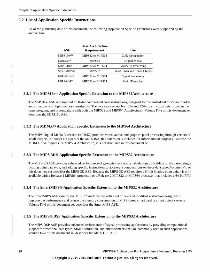
28 MIPS32® Architecture For Programmers Volume I, Revision 2.50
Copyright © 2001-2003,2005 MIPS Technologies Inc. All rights reserved.
Chapter 3 Application Specific Extensions
3.2 List of Application Specific Instructions
As of the publishing date of this document, the following Application Specific Extensions were supported by thearchitecture.
3.2.1 The MIPS16e™ Application Specific Extension to the MIPS32Architecture
The MIPS16e ASE is composed of 16-bit compressed code instructions, designed for the embedded processor marketand situations with tight memory constraints. The core can execute both 16- and 32-bit instructions intermixed in thesame program, and is compatible with both the MIPS32 and MIPS64 Architectures. Volume IV-a of this document setdescribes the MIPS16e ASE.
3.2.2 The MDMX™ Application Specific Extension to the MIPS64 Architecture
The MIPS Digital Media Extension (MDMX) provides video, audio, and graphics pixel processing through vectors ofsmall integers. Although not a part of the MIPS ISA, this extension is included for informational purposes. Because theMDMX ASE requires the MIPS64 Architecture, it is not discussed in this document set.
3.2.3 The MIPS-3D® Application Specific Extension to the MIPS32 Architecture
The MIPS-3D ASE provides enhanced performance of geometry processing calculations by building on the paired singlefloating point data type, and adding specific instructions to accelerate computations on these data types.Volume IV-c ofthis document set describes the MIPS-3D ASE. Because the MIPS-3D ASE requires a 64-bit floating point unit, it is onlyavailable with a Release 1 MIPS64 processor, or a Release 2 MIPS32 or MIPS64 processor that includes a 64-bit FPU.
3.2.4 The SmartMIPS® Application Specific Extension to the MIPS32 Architecture
The SmartMIPS ASE extends the MIPS32 Architecture with a set of new and modified instruction designed toimprove the performance and reduce the memory consumption of MIPS-based smart card or smart object systems.Volume IV-d of this document set describes the SmartMIPS ASE.
3.2.5 The MIPS® DSP Application Specific Extension to the MIPS32 Architecture
The MIPS DSP ASE provides enhanced performance of signal-processing applications by providing computationalsupport for fractional data types, SIMD, saturation, and other elements that are commonly used in such applications.Volume IV-e of this document set describes the MIPS DSP ASE.
ASEBase Architecture
Requirement Use
MIPS16e™ MIPS32 or MIPS64 Code Compaction
MDMX™ MIPS64 Digital Media
MIPS-3D® MIPS32 or MIPS64 Geometry Processing
SmartMIPS® MIPS32 Smart Cards and Smart Objects
MIPS® DSP MIPS32 or MIPS64 Signal Processing
MIPS® MT MIPS32 or MIPS64 Multi-Threading

3.2 List of Application Specific Instructions
MIPS32® Architecture For Programmers Volume I, Revision 2.50 29
Copyright © 2001-2003,2005 MIPS Technologies Inc. All rights reserved.
3.2.6 The MIPS® MT Application Specific Extension to the MIPS32 Architecture
The MIPS MT ASE provides the architecture to support multi-threaded implementations of the Architecture. Thisincludes support for both virtual processors and lightweight thread contexts. Volume IV-f of this document set describesthe MIPS MT ASE.

30 MIPS32® Architecture For Programmers Volume I, Revision 2.50
Copyright © 2001-2003,2005 MIPS Technologies Inc. All rights reserved.
Chapter 3 Application Specific Extensions

MIPS32® Architecture For Programmers Volume I, Revision 2.50 31
Copyright © 2001-2003,2005 MIPS Technologies Inc. All rights reserved.
Chapter 4
Overview of the CPU Instruction Set
This chapter gives an overview of the CPU instructions, including a description of CPU instruction formats. An overviewof the FPU instructions is given in Chapter 5.
4.1 CPU Instructions, Grouped By Function
CPU instructions are organized into the following functional groups:
• Load and store
• Computational
• Jump and branch
• Miscellaneous
• Coprocessor
Each instruction is 32 bits long.
4.1.1 CPU Load and Store Instructions
MIPS processors use a load/store architecture; all operations are performed on operands held in processor registers andmain memory is accessed only through load and store instructions.
4.1.1.1 Types of Loads and Stores
There are several different types of load and store instructions, each designed for a different purpose:
• Transferring variously-sized fields (for example, LB, SW)
• Trading transferred data as signed or unsigned integers (for example, LHU)
• Accessing unaligned fields (for example, LWR, SWL)
• Selecting the addressing mode (for example, SDXC1, in the FPU)
• Atomic memory update (read-modify-write: for instance, LL/SC)
Regardless of the byte ordering (big- or little-endian), the address of a halfword, word, or doubleword is the lowest byteaddress among the bytes forming the object:
• For big-endian ordering, this is the most-significant byte.
• For a little-endian ordering, this is the least-significant byte.
Refer to “Byte Ordering and Endianness” on page 21 for more information on big-endian and little-endian data ordering.

32 MIPS32® Architecture For Programmers Volume I, Revision 2.50
Copyright © 2001-2003,2005 MIPS Technologies Inc. All rights reserved.
Chapter 4 Overview of the CPU Instruction Set
4.1.1.2 Load and Store Access Types
Table 4-1 lists the data sizes that can be accessed through CPU load and store operations. These tables also indicate theparticular ISA within which each operation is defined.
4.1.1.3 List of CPU Load and Store Instructions
The following data sizes (as defined in the AccessLength field) are transferred by CPU load and store instructions:
• Byte
• Halfword
• Word
Signed and unsigned integers of different sizes are supported by loads that either sign-extend or zero-extend the dataloaded into the register.
Table 4-2 lists aligned CPU load and store instructions, while unaligned loads and stores are listed in Table 4-3. Eachtable also lists the MIPS ISA within which an instruction is defined.
Table 4-1 Load and Store Operations Using Register + Offset Addressing Mode
Data Size
CPU Coprocessors 1 and 2
LoadSigned
LoadUnsigned Store Load Store
Byte MIPS32 MIPS32 MIPS32
Halfword MIPS32 MIPS32 MIPS32
Word MIPS32 MIPS64 MIPS32 MIPS32 MIPS32
Doubleword (FPU) MIPS32 MIPS32
Unaligned word MIPS32 MIPS32
Linked word (atomic modify) MIPS32 MIPS32
Table 4-2 Aligned CPU Load/Store Instructions
Mnemonic Instruction Defined in MIPS ISA
LB Load Byte MIPS32
LBU Load Byte Unsigned MIPS32
LH Load Halfword MIPS32
LHU Load Halfword Unsigned MIPS32
LW Load Word MIPS32
SB Store Byte MIPS32
SH Store Halfword MIPS32
SW Store Word MIPS32
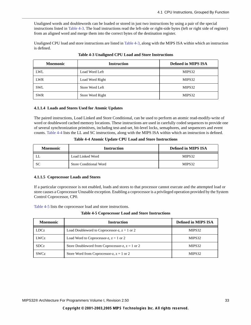
4.1 CPU Instructions, Grouped By Function
MIPS32® Architecture For Programmers Volume I, Revision 2.50 33
Copyright © 2001-2003,2005 MIPS Technologies Inc. All rights reserved.
Unaligned words and doublewords can be loaded or stored in just two instructions by using a pair of the specialinstructions listed in Table 4-3. The load instructions read the left-side or right-side bytes (left or right side of register)from an aligned word and merge them into the correct bytes of the destination register.
Unaligned CPU load and store instructions are listed in Table 4-3, along with the MIPS ISA within which an instructionis defined.
4.1.1.4 Loads and Stores Used for Atomic Updates
The paired instructions, Load Linked and Store Conditional, can be used to perform an atomic read-modify-write ofword or doubleword cached memory locations. These instructions are used in carefully coded sequences to provide oneof several synchronization primitives, including test-and-set, bit-level locks, semaphores, and sequencers and eventcounts. Table 4-4 lists the LL and SC instructions, along with the MIPS ISA within which an instruction is defined.
4.1.1.5 Coprocessor Loads and Stores
If a particular coprocessor is not enabled, loads and stores to that processor cannot execute and the attempted load orstore causes a Coprocessor Unusable exception. Enabling a coprocessor is a privileged operation provided by the SystemControl Coprocessor, CP0.
Table 4-5 lists the coprocessor load and store instructions.
Table 4-3 Unaligned CPU Load and Store Instructions
Mnemonic Instruction Defined in MIPS ISA
LWL Load Word Left MIPS32
LWR Load Word Right MIPS32
SWL Store Word Left MIPS32
SWR Store Word Right MIPS32
Table 4-4 Atomic Update CPU Load and Store Instructions
Mnemonic Instruction Defined in MIPS ISA
LL Load Linked Word MIPS32
SC Store Conditional Word MIPS32
Table 4-5 Coprocessor Load and Store Instructions
Mnemonic Instruction Defined in MIPS ISA
LDCz Load Doubleword to Coprocessor-z, z = 1 or 2 MIPS32
LWCz Load Word to Coprocessor-z, z = 1 or 2 MIPS32
SDCz Store Doubleword from Coprocessor-z, z = 1 or 2 MIPS32
SWCz Store Word from Coprocessor-z, z = 1 or 2 MIPS32

34 MIPS32® Architecture For Programmers Volume I, Revision 2.50
Copyright © 2001-2003,2005 MIPS Technologies Inc. All rights reserved.
Chapter 4 Overview of the CPU Instruction Set
Table 4-6 lists the specific FPU load and store instructions;1 it also lists the MIPS ISA within which an instruction wasfirst defined.
4.1.2 Computational Instructions
This section describes the following:
• “ALU Immediate and Three-Operand Instructions”
• “ALU Two-Operand Instructions”
• “Shift Instructions”
• “Multiply and Divide Instructions”
2’s complement arithmetic is performed on integers represented in 2’s complement notation. These are signed versionsof the following operations:
• Add
• Subtract
• Multiply
• Divide
The add and subtract operations labelled “unsigned” are actually modulo arithmetic without overflow detection.
There are also unsigned versions of multiply and divide, as well as a full complement of shift and logical operations.Logical operations are not sensitive to the width of the register.
MIPS32 provided 32-bit integers and 32-bit arithmetic.
1 FPU loads and stores are listed here with the other coprocessor loads and stores for convenience.
Table 4-6 FPU Load and Store Instructions Using Register + Register Addressing
Mnemonic InstructionDefined in MIPS
ISA
LWXC1 Load Word Indexed to Floating Point MIPS64MIPS32 Release 2
SWXC1 Store Word Indexed from Floating Point MIPS64MIPS32 Release 2
LDXC1 Load Doubleword Indexed to Floating Point MIPS64MIPS32 Release 2
SDXC1 Store Doubleword Indexed from Floating Point MIPS64MIPS32 Release 2
LUXC1 Load Doubleword Indexed Unaligned to Floating Point MIPS64MIPS32 Release 2
SUXC1 Store Doubleword Indexed Unaligned from Floating Point MIPS64MIPS32 Release 2

4.1 CPU Instructions, Grouped By Function
MIPS32® Architecture For Programmers Volume I, Revision 2.50 35
Copyright © 2001-2003,2005 MIPS Technologies Inc. All rights reserved.
4.1.2.1 ALU Immediate and Three-Operand Instructions
Table 4-7 lists those arithmetic and logical instructions that operate on one operand from a register and the other from a16-bit immediate value supplied by the instruction word. This table also lists the MIPS ISA within which an instructionis defined.
The immediate operand is treated as a signed value for the arithmetic and compare instructions, and treated as a logicalvalue (zero-extended to register length) for the logical instructions.
Table 4-8 describes ALU instructions that use three operands, along with the MIPS ISA within which an instruction isdefined.
Table 4-7 ALU Instructions With an Immediate Operand
Mnemonic Instruction Defined in MIPS ISA
ADDI Add Immediate Word MIPS32
ADDIU1
1. The term “unsigned” in the instruction name is a misnomer; this operation is 32-bit modulo arithmetic that does not trap on overflow.
Add Immediate Unsigned Word MIPS32
ANDI And Immediate MIPS32
LUI Load Upper Immediate MIPS32
ORI Or Immediate MIPS32
SLTI Set on Less Than Immediate MIPS32
SLTIU Set on Less Than Immediate Unsigned MIPS32
XORI Exclusive Or Immediate MIPS32
Table 4-8 Three-Operand ALU Instructions
Mnemonic Instruction Defined in MIPS ISA
ADD Add Word MIPS32
ADDU1
1. The term “unsigned” in the instruction name is a misnomer; this operation is 32-bit modulo arithmetic that does not trap on overflow.
Add Unsigned Word MIPS32
AND And MIPS32
NOR Nor MIPS32
OR Or MIPS32
SLT Set on Less Than MIPS32
SLTU Set on Less Than Unsigned MIPS32
SUB Subtract Word MIPS32
SUBU1 Subtract Unsigned Word MIPS32
XOR Exclusive Or MIPS32

36 MIPS32® Architecture For Programmers Volume I, Revision 2.50
Copyright © 2001-2003,2005 MIPS Technologies Inc. All rights reserved.
Chapter 4 Overview of the CPU Instruction Set
4.1.2.2 ALU Two-Operand Instructions
Table 4-8 describes ALU instructions that use two operands, along with the MIPS ISA within which an instruction isdefined.
4.1.2.3 Shift Instructions
The ISA defines two types of shift instructions:
• Those that take a fixed shift amount from a 5-bit field in the instruction word (for instance, SLL, SRL)
• Those that take a shift amount from the low-order bits of a general register (for instance, SRAV, SRLV)
Shift instructions are listed in Table 4-10, along with the MIPS ISA within which an instruction is defined.
4.1.2.4 Multiply and Divide Instructions
The multiply and divide instructions produce twice as many result bits as is typical with other processors. With oneexception, they deliver their results into the HI and LO special registers. The MUL instruction delivers the lower half ofthe result directly to a GPR.
• Multiply produces a full-width product twice the width of the input operands; the low half is loaded into LO and thehigh half is loaded into HI.
• Multiply-Add and Multiply-Subtract produce a full-width product twice the width of the input operations and addsor subtracts the product from the concatenated value of HI and LO. The low half of the addition is loaded into LO andthe high half is loaded into HI.
• Divide produces a quotient that is loaded into LO and a remainder that is loaded into HI.
The results are accessed by instructions that transfer data between HI/LO and the general registers.
Table 4-9 Two-Operand ALU Instructions
Mnemonic Instruction Defined in MIPS ISA
CLO Count Leading Ones in Word MIPS32
CLZ Count Leading Zeros in Word MIPS32
Table 4-10 Shift Instructions
Mnemonic Instruction Defined in MIPS ISA
ROTR Rotate Word Right MIPS32 Release 2
ROTRV Rotate Word Right Variable MIPS32 Release 2
SLL Shift Word Left Logical MIPS32
SLLV Shift Word Left Logical Variable MIPS32
SRA Shift Word Right Arithmetic MIPS32
SRAV Shift Word Right Arithmetic Variable MIPS32
SRL Shift Word Right Logical MIPS32
SRLV Shift Word Right Logical Variable MIPS32

4.1 CPU Instructions, Grouped By Function
MIPS32® Architecture For Programmers Volume I, Revision 2.50 37
Copyright © 2001-2003,2005 MIPS Technologies Inc. All rights reserved.
Table 4-11 lists the multiply, divide, and HI/LO move instructions, along with the MIPS ISA within which an instructionis defined.
4.1.3 Jump and Branch Instructions
This section describes the following:
• “Types of Jump and Branch Instructions Defined by the ISA”
• “Branch Delays and the Branch Delay Slot”
• “Branch and Branch Likely”
• “List of Jump and Branch Instructions”
4.1.3.1 Types of Jump and Branch Instructions Defined by the ISA
The architecture defines the following jump and branch instructions:
• PC-relative conditional branch
• PC-region unconditional jump
• Absolute (register) unconditional jump
• A set of procedure calls that record a return link address in a general register.
4.1.3.2 Branch Delays and the Branch Delay Slot
All branches have an architectural delay of one instruction. The instruction immediately following a branch is said to bein the branch delay slot. If a branch or jump instruction is placed in the branch delay slot, the operation of bothinstructions is undefined.
Table 4-11 Multiply/Divide Instructions
Mnemonic Instruction Defined in MIPS ISA
DIV Divide Word MIPS32
DIVU Divide Unsigned Word MIPS32
MADD Multiply and Add Word MIPS32
MADDU Multiply and Add Word Unsigned MIPS32
MFHI Move From HI MIPS32
MFLO Move From LO MIPS32
MSUB Multiply and Subtract Word MIPS32
MSUBU Multiply and Subtract Word Unsigned MIPS32
MTHI Move To HI MIPS32
MTLO Move To LO MIPS32
MUL Multiply Word to Register MIPS32
MULT Multiply Word MIPS32
MULTU Multiply Unsigned Word MIPS32

38 MIPS32® Architecture For Programmers Volume I, Revision 2.50
Copyright © 2001-2003,2005 MIPS Technologies Inc. All rights reserved.
Chapter 4 Overview of the CPU Instruction Set
By convention, if an exception or interrupt prevents the completion of an instruction in the branch delay slot, theinstruction stream is continued by re-executing the branch instruction. To permit this, branches must be restartable;procedure calls may not use the register in which the return link is stored (usually GPR 31) to determine the branch targetaddress.
4.1.3.3 Branch and Branch Likely
There are two versions of conditional branches; they differ in the manner in which they handle the instruction in the delayslot when the branch is not taken and execution falls through.
• Branch instructions execute the instruction in the delay slot.
• Branch likely instructions do not execute the instruction in the delay slot if the branch is not taken (they are said tonullify the instruction in the delay slot).
Although the Branch Likely instructions are included in this specification, software is strongly encouraged toavoid the use of the Branch Likely instructions, as they will be removed from a future revision of the MIPSArchitecture.
4.1.3.4 List of Jump and Branch Instructions
Table 4-12 lists instructions that jump to a procedure call within the current 256 MB-aligned region, or to an absoluteaddress held in a register.
Table 4-12 lists the unconditional jump instructions within a given 256 MByte region. Table 4-13 lists branchinstructions that compare two registers before conditionally executing a PC-relative branch. Table 4-14 lists branchinstructions that test a register—compare with zero—before conditionally executing a PC-relative branch. Table 4-15lists the deprecated Branch Likely Instructions.
Each table also lists the MIPS ISA within which an instruction is defined.
Table 4-12 Unconditional Jump Within a 256 Megabyte Region
Mnemonic Instruction Location to Which Jump Is MadeDefined in MIPS
ISA
J Jump 256 Megabyte Region MIPS32
JAL Jump and Link 256 Megabyte Region MIPS32
JALR Jump and Link Register Absolute Address MIPS32
JALR.HB Jump and Link Register withHazard Barrier Absolute Address MIPS32 Release 2
JALX Jump and Link Exchange Absolute Address MIPS16e
JR Jump Register Absolute Address MIPS32
JR.HB Jump Register with HazardBarrier Absolute Address MIPS32 Release 2
Table 4-13 PC-Relative Conditional Branch Instructions Comparing Two Registers
Mnemonic InstructionDefined in MIPS
ISA
BEQ Branch on Equal MIPS32
BNE Branch on Not Equal MIPS32

4.1 CPU Instructions, Grouped By Function
MIPS32® Architecture For Programmers Volume I, Revision 2.50 39
Copyright © 2001-2003,2005 MIPS Technologies Inc. All rights reserved.
4.1.4 Miscellaneous Instructions
Miscellaneous instructions include:
• “Instruction Serialization (SYNC and SYNCI)”
• “Exception Instructions”
• “Conditional Move Instructions”
• “Prefetch Instructions”
• “NOP Instructions”
4.1.4.1 Instruction Serialization (SYNC and SYNCI)
In normal operation, the order in which load and store memory accesses appear to a viewer outside the executingprocessor (for instance, in a multiprocessor system) is not specified by the architecture.
The SYNC instruction can be used to create a point in the executing instruction stream at which the relative order ofsome loads and stores can be determined: loads and stores executed before the SYNC are completed before loads andstores after the SYNC can start.
Table 4-14 PC-Relative Conditional Branch Instructions Comparing With Zero
Mnemonic InstructionDefined in MIPS
ISA
BGEZ Branch on Greater Than or Equal to Zero MIPS32
BGEZAL Branch on Greater Than or Equal to Zero and Link MIPS32
BGTZ Branch on Greater Than Zero MIPS32
BLEZ Branch on Less Than or Equal to Zero MIPS32
BLTZ Branch on Less Than Zero MIPS32
BLTZAL Branch on Less Than Zero and Link MIPS32
Table 4-15 Deprecated Branch Likely Instructions
Mnemonic InstructionDefined in MIPS
ISA
BEQL Branch on Equal Likely MIPS32
BGEZALL Branch on Greater Than or Equal to Zero and Link Likely MIPS32
BGEZL Branch on Greater Than or Equal to Zero Likely MIPS32
BGTZL Branch on Greater Than Zero Likely MIPS32
BLEZL Branch on Less Than or Equal to Zero Likely MIPS32
BLTZALL Branch on Less Than Zero and Link Likely MIPS32
BLTZL Branch on Less Than Zero Likely MIPS32
BNEL Branch on Not Equal Likely MIPS32

40 MIPS32® Architecture For Programmers Volume I, Revision 2.50
Copyright © 2001-2003,2005 MIPS Technologies Inc. All rights reserved.
Chapter 4 Overview of the CPU Instruction Set
The SYNCI instruction synchronizes the processor caches with previous writes or other modifications to the instructionstream.
Table 4-16 lists the synchronization instructions, along with the MIPS ISA within which it is defined.
4.1.4.2 Exception Instructions
Exception instructions transfer control to a software exception handler in the kernel. There are two types of exceptions,conditional and unconditional. These are caused by the following instructions:
Trap instructions, which cause conditional exceptions based upon the result of a comparison
System call and breakpoint instructions, which cause unconditional exceptions
Table 4-17 lists the system call and breakpoint instructions. Table 4-18 lists the trap instructions that compare tworegisters. Table 4-19 lists trap instructions, which compare a register value with an immediate value.
Each table also lists the MIPS ISA within which an instruction is defined.
Table 4-16 Serialization Instruction
Mnemonic Instruction Defined in MIPS ISA
SYNC Synchronize Shared Memory MIPS32
SYNCI Synchronize Caches to Make Instruction Writes Effective MIPS32 Release 2
Table 4-17 System Call and Breakpoint Instructions
Mnemonic Instruction Defined in MIPS ISA
BREAK Breakpoint MIPS32
SYSCALL System Call MIPS32
Table 4-18 Trap-on-Condition Instructions Comparing Two Registers
Mnemonic Instruction Defined in MIPS ISA
TEQ Trap if Equal MIPS32
TGE Trap if Greater Than or Equal MIPS32
TGEU Trap if Greater Than or Equal Unsigned MIPS32
TLT Trap if Less Than MIPS32
TLTU Trap if Less Than Unsigned MIPS32II
TNE Trap if Not Equal MIPS32
Table 4-19 Trap-on-Condition Instructions Comparing an Immediate Value
Mnemonic Instruction Defined in MIPS ISA
TEQI Trap if Equal Immediate MIPS32
TGEI Trap if Greater Than or Equal Immediate MIPS32
TGEIU Trap if Greater Than or Equal Immediate Unsigned MIPS32

4.1 CPU Instructions, Grouped By Function
MIPS32® Architecture For Programmers Volume I, Revision 2.50 41
Copyright © 2001-2003,2005 MIPS Technologies Inc. All rights reserved.
4.1.4.3 Conditional Move Instructions
MIPS32 includes instructions to conditionally move one CPU general register to another, based on the value in a thirdgeneral register. For floating point conditional moves, refer to Chapter 4.
Table 4-20 lists conditional move instructions, along with the MIPS ISA within which an instruction is defined.
4.1.4.4 Prefetch Instructions
There are two prefetch advisory instructions:
• One with register+offset addressing (PREF)
• One with register+register addressing (PREFX)
These instructions advise that memory is likely to be used in a particular way in the near future and should be prefetchedinto the cache. The PREFX instruction is encoded in the FPU opcode space, along with the other operations usingregister+register addressing
4.1.4.5 NOP Instructions
The NOP instruction is actually encoded as an all-zero instruction. MIPS processors special-case this encoding asperforming no operation, and optimize execution of the instruction. In addition, SSNOP instruction, takes up one issuecycle on any processor, including super-scalar implementations of the architecture.
TLTI Trap if Less Than Immediate MIPS32
TLTIU Trap if Less Than Immediate Unsigned MIPS32
TNEI Trap if Not Equal Immediate MIPS32
Table 4-20 CPU Conditional Move Instructions
Mnemonic Instruction Defined in MIPS ISA
MOVF Move Conditional on Floating Point False MIPS32
MOVN Move Conditional on Not Zero MIPS32
MOVT Move Conditional on Floating Point True MIPS32
MOVZ Move Conditional on Zero MIPS32
Table 4-21 Prefetch Instructions
Mnemonic Instruction Addressing Mode Defined in MIPS ISA
PREF Prefetch Register+Offset MIPS32
PREFX Prefetch Indexed Register+Register MIPS64
Table 4-19 Trap-on-Condition Instructions Comparing an Immediate Value
Mnemonic Instruction Defined in MIPS ISA

42 MIPS32® Architecture For Programmers Volume I, Revision 2.50
Copyright © 2001-2003,2005 MIPS Technologies Inc. All rights reserved.
Chapter 4 Overview of the CPU Instruction Set
Table 4-22 lists conditional move instructions, along with the MIPS ISA within which an instruction is defined.
4.1.5 Coprocessor Instructions
This section contains information about the following:
• “What Coprocessors Do”
• “System Control Coprocessor 0 (CP0)”
• “Floating Point Coprocessor 1 (CP1)”
• “Coprocessor Load and Store Instructions”
4.1.5.1 What Coprocessors Do
Coprocessors are alternate execution units, with register files separate from the CPU. In abstraction, the MIPSarchitecture provides for up to four coprocessor units, numbered 0 to 3. Each level of the ISA defines a number of thesecoprocessors, as listed in Table 4-23.
Coprocessor 0 is always used for system control and coprocessor 1 and 3 are used for the floating point unit. Coprocessor2 is reserved for implementation-specific use.
A coprocessor may have two different register sets:
• Coprocessor general registers
• Coprocessor control registers
Each set contains up to 32 registers. Coprocessor computational instructions may use the registers in either set.
Table 4-22 NOP Instructions
Mnemonic Instruction Defined in MIPS ISA
NOP No Operation MIPS32
SSNOP Superscalar Inhibit NOP MIPS32
Table 4-23 Coprocessor Definition and Use in the MIPS Architecture
Coprocessor MIPS32 MIPS64
CP0 Sys Control Sys Control
CP1 FPU FPU
CP2 implementation specific
CP3 See Footnote FPU (COP1X)

4.2 CPU Instruction Formats
MIPS32® Architecture For Programmers Volume I, Revision 2.50 43
Copyright © 2001-2003,2005 MIPS Technologies Inc. All rights reserved.
4.1.5.2 System Control Coprocessor 0 (CP0)
The system controller for all MIPS processors is implemented as coprocessor 0 (CP01), the System ControlCoprocessor. It provides the processor control, memory management, and exception handling functions.
4.1.5.3 Floating Point Coprocessor 1 (CP1)
If a system includes a Floating Point Unit, it is implemented as coprocessor 1 (CP12). In Release 1 of the MIPS64ARchitecture, and in Release 2 of the MIPS32 and MIPS64 Architectures, the FPU also uses the computation opcodespace assigned to coprocessor unit 3, renamed COP1X. Details of the FPU instructions are documented in Chapter 5,“Overview of the FPU Instruction Set,” on page 45.
Coprocessor instructions are divided into two main groups:
• Load and store instructions (move to and from coprocessor), which are reserved in the main opcode space
• Coprocessor-specific operations, which are defined entirely by the coprocessor
4.1.5.4 Coprocessor Load and Store Instructions
Explicit load and store instructions are not defined for CP0; for CP0 only, the move to and from coprocessor instructionsmust be used to write and read the CP0 registers. The loads and stores for the remaining coprocessors are summarizedin “Coprocessor Loads and Stores” on page 33.
4.2 CPU Instruction Formats
A CPU instruction is a single 32-bit aligned word. The CPU instruction formats are shown below:
• Immediate (see Figure 4-1)
• Jump (see Figure 4-2)
• Register (see Figure 4-3)
1 CP0 instructions use the COP0 opcode, and as such are differentiated from the CP0 designation in this book.
2 FPU instructions (such as LWC1, SDC1, etc.) that use the COP1 opcode are differentiated from the CP1 designation in this book. SeeChapter 5, “Overview of the FPU Instruction Set,” on page 45 for more information about the FPU instructions.

44 MIPS32® Architecture For Programmers Volume I, Revision 2.50
Copyright © 2001-2003,2005 MIPS Technologies Inc. All rights reserved.
Chapter 4 Overview of the CPU Instruction Set
Table 4-24 describes the fields used in these instructions.
Figure 4-1 Immediate (I-Type) CPU Instruction Format
Figure 4-2 Jump (J-Type) CPU Instruction Format
Figure 4-3 Register (R-Type) CPU Instruction Format
Table 4-24 CPU Instruction Format Fields
Field Description
opcode 6-bit primary operation code
rd 5-bit specifier for the destination register
rs 5-bit specifier for the source register
rt 5-bit specifier for the target (source/destination) register or used to specify functions within theprimary opcode REGIMM
immediate 16-bit signed immediate used for logical operands, arithmetic signed operands, load/storeaddress byte offsets, and PC-relative branch signed instruction displacement
instr_index 26-bit index shifted left two bits to supply the low-order 28 bits of the jump target address
sa 5-bit shift amount
function 6-bit function field used to specify functions within the primary opcode SPECIAL
31 26 25 21 20 16 15 0
opcode rs rt immediate
6 5 5 16
31 26 25 21 20 16 15 11 10 6 5 0
opcode instr_index
6 26
31 26 25 21 20 16 15 11 10 6 5 0
opcode rs rt rd sa function
6 5 5 5 5 6

MIPS32® Architecture For Programmers Volume I, Revision 2.50 45
Copyright © 2001-2003,2005 MIPS Technologies Inc. All rights reserved.
Chapter 5
Overview of the FPU Instruction Set
This chapter describes the instruction set architecture (ISA) for the floating point unit (FPU) in the MIPS32 architecture.In the MIPS architecture, the FPU is implemented via Coprocessor 1 and Coprocessor 3, an optional processorimplementing IEEE Standard 7541 floating point operations. The FPU also provides a few additional operations notdefined by the IEEE standard.
This chapter provides an overview of the following FPU architectural details:
• Section 5.1, "Binary Compatibility"
• Section 5.2, "Enabling the Floating Point Coprocessor"
• Section 5.3, "IEEE Standard 754"
• Section 5.4, "FPU Data Types"
• Section 5.5, "Floating Point Register Types"
• Section 5.6, "Floating Point Control Registers (FCRs)"
• Section 5.7, "Formats of Values Used in FP Registers"
• Section 5.8, "FPU Exceptions"
• Section 5.9, "FPU Instructions"
• Section 5.10, "Valid Operands for FPU Instructions"
• Section 5.11, "FPU Instruction Formats"
The FPU instruction set is summarized by functional group. Each instruction is also described individually inalphabetical order in Volume II.
5.1 Binary Compatibility
In addition to an Instruction Set Architecture, the MIPS architecture definition includes processing resources such as theset of coprocessor general registers. In Release 1 of the Architecture, the 32-bit registers in MIPS32 were enlarged to64-bits in MIPS64; however, these 64-bit FPU registers are not backwards compatible. Instead, processors implementingthe MIPS64 Architecture provide a mode bit to select either the 32-bit or 64-bit register model. In Release 2 of theArchitecture, a 32-bit CPU may include a full 64-bit coprocessor, including a floating point unit which implements thesame mode bit to select 32-bit or 64-bit FPU register model.
Any processor implementing MIPS64 can also run MIPS32 binary programs, built for the same, or a lower release ofthe Architecture, without change.
1 In this chapter, references to “IEEE standard” and “IEEE Standard 754” refer to IEEE Standard 754-1985, “IEEE Standard for BinaryFloating Point Arithmetic.” For more information about this standard, see the IEEE web page at http://stdsbbs.ieee.org/.

46 MIPS32® Architecture For Programmers Volume I, Revision 2.50
Copyright © 2001-2003,2005 MIPS Technologies Inc. All rights reserved.
Chapter 5 Overview of the FPU Instruction Set
5.2 Enabling the Floating Point Coprocessor
Enabling the Floating Point Coprocessor is done by enabling Coprocessor 1, and is a privileged operation provided bythe System Control Coprocessor. If Coprocessor 1 is not enabled, an attempt to execute a floating point instruction causesa Coprocessor Unusable exception. Every system environment either enables the FPU automatically or provides a meansfor an application to request that it is enabled.
5.3 IEEE Standard 754
IEEE Standard 754 defines the following:
• Floating point data types
• The basic arithmetic, comparison, and conversion operations
• A computational model
The IEEE standard does not define specific processing resources nor does it define an instruction set.
The MIPS architecture includes non-IEEE FPU control and arithmetic operations (multiply-add, reciprocal, andreciprocal square root) which may not supply results that match the IEEE precision rules.
5.4 FPU Data Types
The FPU provides both floating point and fixed point data types, which are described in the next two sections.
• The single and double precision floating point data types are those specified by the IEEE standard.
• The fixed point types are signed integers provided by the CPU architecture.
5.4.1 Floating Point Formats
The following two floating point formats are provided by the FPU:
• 32-bit single precision floating point (type S, shown in Figure 5-1)
• 64-bit double precision floating point (type D, shown in Figure 5-2)
• 64-bit paired single floating point, combining two single precision data types (Type PS, shown in Figure 5-3)
The floating point data types represent numeric values as well as other special entities, such as the following:
• Two infinities, +∞ and -∞
• Signaling non-numbers (SNaNs)
• Quiet non-numbers (QNaNs)s

5.4 FPU Data Types
MIPS32® Architecture For Programmers Volume I, Revision 2.50 47
Copyright © 2001-2003,2005 MIPS Technologies Inc. All rights reserved.
• Numbers of the form: (-1)s 2E b0.b1 b2..bp-1, where:
– s=0 or 1
– E=any integer between E_min and E_max, inclusive
– bi=0 or 1 (the high bit, b0, is to the left of the binary point)
– p is the signed-magnitude precision
The single and double floating point data types are composed of three fields—sign, exponent, fraction—whose sizes arelisted in Table 5-1.
Layouts of these fields are shown in Figures 5-1, 5-2, and 5-3 below. The fields are
• 1-bit sign, s
• Biased exponent, e=E + bias
• Binary fraction, f=.b1 b2..bp-1 (the b0 bit is not recorded)
Figure 5-1 Single-Precisions Floating Point Format (S)
Figure 5-2 Double-Precisions Floating Point Format (D)
Table 5-1 Parameters of Floating Point Data Types
ParameterSingle (or each half
of Paired Single) Double
Bits of mantissa precision, p 24 53
Maximum exponent, E_max +127 +1023
Minimum exponent, E_min -126 -1022
Exponent bias +127 +1023
Bits in exponent field, e 8 11
Representation of b0 integer bit hidden hidden
Bits in fraction field, f 23 52
Total format width in bits 32 64
31
30
23
22
0
S Exponent Fraction
1 8 23
63
62
52
51
0
S Exponent Fraction
1 11 52

48 MIPS32® Architecture For Programmers Volume I, Revision 2.50
Copyright © 2001-2003,2005 MIPS Technologies Inc. All rights reserved.
Chapter 5 Overview of the FPU Instruction Set
Figure 5-3 Paired Single Floating Point Format (PS)
Values are encoded in the specified format by using unbiased exponent, fraction, and sign values listed in Table 5-2. Thehigh-order bit of the Fraction field, identified as b1, is also important for NaNs.
5.4.1.1 Normalized and Denormalized Numbers
For single and double data types, each representable nonzero numerical value has just one encoding; numbers are keptin normalized form. The high-order bit of the p-bit mantissa, which lies to the left of the binary point, is “hidden,” andnot recorded in the Fraction field. The encoding rules permit the value of this bit to be determined by looking at the valueof the exponent. When the unbiased exponent is in the range E_min to E_max, inclusive, the number is normalized andthe hidden bit must be 1. If the numeric value cannot be normalized because the exponent would be less than E_min,then the representation is denormalized and the encoded number has an exponent of E_min-1 and the hidden bit has thevalue 0. Plus and minus zero are special cases that are not regarded as denormalized values.
5.4.1.2 Reserved Operand Values—Infinity and NaN
A floating point operation can signal IEEE exception conditions, such as those caused by uninitialized variables,violations of mathematical rules, or results that cannot be represented. If a program does not choose to trap IEEEexception conditions, a computation that encounters these conditions proceeds without trapping but generates a result
63
62
55
54
32
31
30
23
22
0
S Exponent fraction S Exponent Fraction
1 8 23 1 8 23
Table 5-2 Value of Single or Double Floating Point DataType Encoding
Unbiased E f s b1 Value V Type of ValueTypicalSingleBit Pattern1
1. The "Typical" nature of the bit patterns for the NaN and denormalized values reflects the fact that the sign may have either value (NaN) and the fact thatthe fraction field may have any non-zero value (both). As such, the bit patterns shown are one value in a class of potential values that represent thesespecial values.
Typical Double BitPattern1.
E_max + 1 ≠ 01 SNaN Signaling NaN 0x7fffffff 0x7fffffff ffffffff
0 QNaN Quiet NaN 0x7fbfffff 0x7ff7ffff ffffffff
E_max +1 01 - ∞ minus infinity 0xff800000 0xfff00000 00000000
0 + ∞ plus infinity 0x7f800000 0x7ff00000 00000000
E_max to
E_min
1 - (2E)(1.f) negative normalizednumber
0x80800000 through0xff7fffff
0x80100000 00000000 through0xffefffff ffffffff
0 + (2E)(1.f) positive normalized number0x00800000 through0x7f7fffff
0x00100000 00000000 through0x7fefffff ffffffff
E_min -1 ≠ 0
1 - (2E_min)(0.f) negative denormalizednumber 0x807fffff 0x800fffff ffffffff
0 + (2E_min)(0.f) positive denormalizednumber 0x007fffff 0x00ffffff ffffffff
E_min -1 01 - 0 negative zero 0x80000000 0x80000000 00000000
0 + 0 positive zero 0x00000000 0x00000000 00000000

5.4 FPU Data Types
MIPS32® Architecture For Programmers Volume I, Revision 2.50 49
Copyright © 2001-2003,2005 MIPS Technologies Inc. All rights reserved.
indicating that an exceptional condition arose during the computation. To permit this, each floating point format definesrepresentations, listed in Table 5-2, for plus infinity (+∞), minus infinity (-∞), quiet non-numbers (QNaN), and signalingnon-numbers (SNaN).
5.4.1.3 Infinity and Beyond
Infinity represents a number with magnitude too large to be represented in the format; in essence it exists to represent amagnitude overflow during a computation. A correctly signed ∞ is generated as the default result in division by zero andsome cases of overflow; details are given in the IEEE exception condition described in.
Once created as a default result, ∞ can become an operand in a subsequent operation. The infinities are interpreted suchthat -∞ < (every finite number) < +∞. Arithmetic with ∞ is the limiting case of real arithmetic with operands ofarbitrarily large magnitude, when such limits exist. In these cases, arithmetic on ∞ is regarded as exact and exceptionconditions do not arise. The out-of-range indication represented by ∞ is propagated through subsequent computations.For some cases there is no meaningful limiting case in real arithmetic for operands of ∞, and these cases raise the InvalidOperation exception condition (see “Invalid Operation Exception” on page 62).
5.4.1.4 Signalling Non-Number (SNaN)
SNaN operands cause the Invalid Operation exception for arithmetic operations. SNaNs are useful values to put inuninitialized variables. An SNaN is never produced as a result value.
IEEE Standard 754 states that “Whether copying a signaling NaN without a change of format signals the InvalidOperation exception is the implementor’s option.” The MIPS architecture has chosen to make the formatted operandmove instructions (MOV.fmt MOVT.fmt MOVF.fmt MOVN.fmt MOVZ.fmt) non-arithmetic and they do not signalIEEE 754 exceptions.
5.4.1.5 Quiet Non-Number (QNaN)
QNaNs are intended to afford retrospective diagnostic information inherited from invalid or unavailable data and results.Propagation of the diagnostic information requires information contained in a QNaN to be preserved through arithmeticoperations and floating point format conversions.
QNaN operands do not cause arithmetic operations to signal an exception. When a floating point result is to be delivered,a QNaN operand causes an arithmetic operation to supply a QNaN result. When possible, this QNaN result is one of theoperand QNaN values. QNaNs do have effects similar to SNaNs on operations that do not deliver a floating point result—specifically, comparisons. (For more information, see the detailed description of the floating point compare instruction,C.cond.fmt.)
When certain invalid operations not involving QNaN operands are performed but do not trap (because the trap is notenabled), a new QNaN value is created. Table 5-3 shows the QNaN value generated when no input operand QNaN valuecan be copied. The values listed for the fixed point formats are the values supplied to satisfy the IEEE standard when aQNaN or infinite floating point value is converted to fixed point. There is no other feature of the architecture that detectsor makes use of these “integer QNaN” values.
Table 5-3 Value Supplied When a New Quiet NaN Is Created
Format New QNaN value
Single floating point 0x7fbf ffff
Double floating point 0x7ff7 ffff ffff ffff
Word fixed point 0x7fff ffff
Longword fixed point 0x7fff ffff ffff ffff

50 MIPS32® Architecture For Programmers Volume I, Revision 2.50
Copyright © 2001-2003,2005 MIPS Technologies Inc. All rights reserved.
Chapter 5 Overview of the FPU Instruction Set
5.4.1.6 Paired Single Exceptions
Exception conditions that arise while executing the two halves of a floating point vector operation are ORed together,and the instruction is treated as having caused all the exceptional conditions arising from both operations. The hardwaremakes no effort to determine which of the two operations encountered the exceptional condition.
5.4.1.7 Paired Single Condition Codes
The c.cond.PS instruction compares the upper and lower halves of FPR fs and FPR ft independently and writes theresults into condition codes CC +1 and CC respectively. The CC number must be even. If the number is not even theoperation of the instruction is UNPREDICTABLE.
5.4.2 Fixed Point Formats
The FPU provides two fixed point data types:
• 32-bit Word fixed point (type W), shown in Figure 5-4
• 64-bit Longword fixed point (type L), shown in Figure 5-5
The fixed point values are held in the 2’s complement format used for signed integers in the CPU. Unsigned fixed pointdata types are not provided by the architecture; application software may synthesize computations for unsigned integersfrom the existing instructions and data types.
Figure 5-4 Word Fixed Point Format (W)
Figure 5-5 Longword Fixed Point Format (L)
5.5 Floating Point Register Types
This section describes the organization and use of the two types of FPU register sets:
In Release 1 of the Architecture, 64-bit floating point units were supported only by implementations of the MIPS64Architecture. Similarly, implementations of MIPS32 of the Architecture only supported 32-bit floating point units. InRelease 2 of the Architecture, a 64-bit floating point unit is supported on implementations of both the MIPS32 andMIPS64 Architectures.
Floating Point registers (FPRs) are 32 or 64 bits wide. A 32-bit floating point unit contains 32 32-bit FPRs, each of whichis capable of storing a 32-bit data type. Double-precision (type D) data types are stored in even-odd pairs of FPRs, andthe long-integer (type L) and paired single (type PS) data types are not supported. A 64-bit floating point unit contains
31
30
0
S Integer
1 31
63
62
0
S Integer
1 63

5.5 Floating Point Register Types
MIPS32® Architecture For Programmers Volume I, Revision 2.50 51
Copyright © 2001-2003,2005 MIPS Technologies Inc. All rights reserved.
32 64-bit FPRs, each of which is capable of storing any data type. For compatibility with 32-bit FPUs, the FR bit in theCP0 Status register is used by a MIPS64 Release 1, or any Release 2 processor that supports a 64-bit FPU to configurethe FPU in a mode in which the FPRs are treated as 32 32-bit registers, each of which is capable of storing only 32-bitdata types. In this mode, the double-precision floating point (type D) data type is stored in even-odd pairs of FPRs, andthe long-integer (type L) and paired single (type PS) data types are not supported.
• These registers transfer binary data between the FPU and the system, and are also used to hold formatted FPUoperand values. Refer to Volume III, The MIPS Privileged Architecture Manual, for more information on the CP0Registers.
• Floating Point Control registers (FCRs), which are 32 bits wide. There are five FPU control registers, used to identifyand control the FPU. These registers are indicated by the fs field of the instruction word. Three of these registers,FCCR, FEXR, and FENR, select subsets of the floating point Control/Status register, the FCSR.
5.5.1 FPU Register Models
There are separate FPU register models in Release 1 of the Architecture:
• MIPS32 defines 32 32-bit registers, with D-format values stored in even-odd pairs of registers.
• MIPS64 defines 32 64-bit registers, with all formats supported in a register.
To support MIPS32 programs, MIPS64 processors also provide the MIPS32 register model, which is available as a modeselection through the FR Bit of the CP0 Status Register.
In Release 2 of the Architecture, both FPU register models are supported in MIPS32 (as well as MIPS64)implementations, and the FR bit of the CP0 Status Register.
5.5.2 Binary Data Transfers (32-Bit and 64-Bit)
The data transfer instructions move words and doublewords between the FPU FPRs and the remainder of the system.The operations of the word and doubleword load and move-to instructions are shown in Figure 5-6 and Figure 5-7.
The store and move-from instructions operate in reverse, reading data from the location which the corresponding loador move-to instruction wrote.
Figure 5-6 FPU Word Load and Move-to Operations
Reg 0
Reg 1
63 0FR BIT = 1 FR BIT = 0
Reg 0
Reg 1
Reg 0
Reg 1
Initial value 1
Initial value 2
Undefined/Unused Data word (0)
Initial value 2
Undefined/Unused
Undefined/Unused
Data word (0)
Data word (4)
63 0
63 0
63 0
63 0
63 0
Reg 0
Reg 2
Reg 0
Reg 2
Reg 0
Reg 2
Undefined/Unused Data word (0)
Initial value 2
Data word (4) Data word (0)
Initial value 2
Initial value 1
Initial value 2
LWC1 f0, 0(r0) / MTC1 f0,r0
LWC1 f1, 4(r0) / MTC1 f1,r4
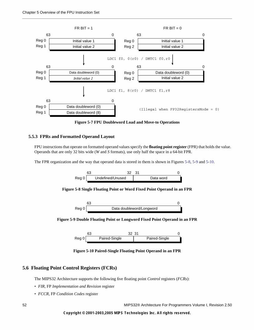
52 MIPS32® Architecture For Programmers Volume I, Revision 2.50
Copyright © 2001-2003,2005 MIPS Technologies Inc. All rights reserved.
Chapter 5 Overview of the FPU Instruction Set
Figure 5-7 FPU Doubleword Load and Move-to Operations
5.5.3 FPRs and Formatted Operand Layout
FPU instructions that operate on formatted operand values specify the floating point register (FPR) that holds the value.Operands that are only 32 bits wide (W and S formats), use only half the space in a 64-bit FPR.
The FPR organization and the way that operand data is stored in them is shown in Figures 5-8, 5-9 and 5-10.
Figure 5-8 Single Floating Point or Word Fixed Point Operand in an FPR
Figure 5-9 Double Floating Point or Longword Fixed Point Operand in an FPR
Figure 5-10 Paired-Single Floating Point Operand in an FPR
5.6 Floating Point Control Registers (FCRs)
The MIPS32 Architecture supports the following five floating point Control registers (FCRs):
• FIR, FP Implementation and Revision register
• FCCR, FP Condition Codes register
Initial value 2
Data doubleword (0)
Reg 0
Reg 1
63 0
FR BIT = 1 FR BIT = 0
Initial value 1
Initial value 2
Data doubleword (0)
63 0
63 0
63 0
Reg 0
Reg 2
LDC1 f0, 0(r0) / DMTC1 f0,r0
LDC1 f1, 8(r0) / DMTC1 f1,r8
Reg 0
Reg 1
Reg 0
Reg 1
Initial value 1
Initial value 2
Reg 0
Reg 2 Initial value 2
Data doubleword (0)
Data doubleword (8)
63 0
(Illegal when FP32RegistersMode = 0)
63 32 31 0Reg 0 Undefined/Unused Data word
63 0Reg 0 Data doubleword/Longword
63 0Reg 0 Paired-Single
32 31Paired-Single

5.6 Floating Point Control Registers (FCRs)
MIPS32® Architecture For Programmers Volume I, Revision 2.50 53
Copyright © 2001-2003,2005 MIPS Technologies Inc. All rights reserved.
• FEXR, FP Exceptions register
• FENR, FP Enables register
• FCSR, FP Control/Status register (used to be known as FCR31).
FCCR, FEXR, and FENR access portions of the FCSR through CTC1 and CFC1 instructions.
Access to the Floating Point Control Registers is not privileged; they can be accessed by any program that can executefloating point instructions. The FCRs can be accessed via the CTC1 and CFC1 instructions.
5.6.1 Floating Point Implementation Register (FIR, CP1 Control Register 0)
Compliance Level: Required if floating point is implemented
The Floating Point Implementation Register (FIR) is a 32-bit read-only register that contains information identifying thecapabilities of the floating point unit, the floating point processor identification, and the revision level of the floatingpoint unit. Figure 5-11 shows the format of the FIR register; Table 5-4 describes the FIR register fields.
Figure 5-11 FIR Register Format
31 28 27 24 23 22 21 20 19 18 17 16 15 8 7 0
00000 Impl 0 F6
4 L W 3D PS D S ProcessorID Revision
Table 5-4 FIR Register Field Descriptions
Fields
DescriptionRead/Write Reset State ComplianceName Bits
0 31:28 Reserved for future use; reads as zero 0 0 Reserved
Impl 27..24
These bits are implementation dependent and are notdefined by the architecture, other than the fact that theyare read-only. This bits are explicitly not intended to beused for mode control functions.
R Preset Optional
0 23 Reserved for future use; reads as zero 0 0 Reserved
F64 22
Indicates that the floating point unit has registers anddata paths that are 64-bits wide. This bit was added inRelease 2 of the Architecture, and is a one on eitherMIPS32 or MIPS64 processors with a 64-bit floatingpoint unit, and a zero on MIPS32 or MIPS64processors with a 32-bit floating point unit. A value ofone in this bit indicates that StatusFR is implemented. R Preset Required
(Release 2)
L 21
Indicates that the longword fixed point (L) data typeand instructions are implemented:
R Preset Required(Release 2)
Encoding Meaning
0 FPU is 32 bits
1 FPU is 64 bits
Encoding Meaning
0 L fixed point not implemented
1 L fixed point implemented

54 MIPS32® Architecture For Programmers Volume I, Revision 2.50
Copyright © 2001-2003,2005 MIPS Technologies Inc. All rights reserved.
Chapter 5 Overview of the FPU Instruction Set
W 20
Indicates that the word fixed point (W) data type andinstructions are implemented:
RPreset or
ExternallySet
Required(Release 2)
3D 19
In Release 1 of the Architecture, this bit is used byMIPS64 processors to indicate that the MIPS-3D ASEis implemented. It is not used by MIPS32 processorsand reads as zero.
In Release 2 of the Architecture, the MIPS-3D ASE issupported on both MIPS32 and MIPS64 processorswith a 64-bit floating point unit, and this bit indicatesthat the MIPS-3D ASE is implemented: R Preset Required
PS 18
In Release 1 of the Architecture, this bit is used byMIPS64 processors to indicate that the paired singlefloating point data type is implemented. It is not usedby MIPS32 processors and reads as zero.
In Release 2 of the Architecture, the paired singlefloating point data type is supported on both MIPS32and MIPS64 processors with a 64-bit floating pointunit, and this bit indicates that the paired single floatingpoint data type is implemented:
R Preset Required
D 17
Indicates that the double-precision (D) floating pointdata type and instructions are implemented:
R Preset Required
S 16
Indicates that the single-precision (S) floating pointdata type and instructions are implemented:
R Preset Required
ProcessorID 15:8 Identifies the floating point processor. R Preset Required
Table 5-4 FIR Register Field Descriptions
Fields
DescriptionRead/Write Reset State ComplianceName Bits
Encoding Meaning
0 W fixed point not implemented
1 W fixed point implemented
Encoding Meaning
0 MIPS-3D ASE not implemented
1 MIPS-3D ASE implemented
Encoding Meaning
0 PS floating point not implemented
1 PS floating point implemented
Encoding Meaning
0 D floating point not implemented
1 D floating point implemented
Encoding Meaning
0 S floating point not implemented
1 S floating point implemented

5.6 Floating Point Control Registers (FCRs)
MIPS32® Architecture For Programmers Volume I, Revision 2.50 55
Copyright © 2001-2003,2005 MIPS Technologies Inc. All rights reserved.
5.6.2 Floating Point Control and Status Register (FCSR, CP1 Control Register 31)
Compliance Level: Required if floating point is implemented.
The Floating Point Control and Status Register (FCSR) is a 32-bit register that controls the operation of the floating pointunit, and shows the following status information:
• selects the default rounding mode for FPU arithmetic operations
• selectively enables traps of FPU exception conditions
• controls some denormalized number handling options
• reports any IEEE exceptions that arose during the most recently executed instruction
• reports IEEE exceptions that arose, cumulatively, in completed instructions
• indicates the condition code result of FP compare instructions
Access to FCSR is not privileged; it can be read or written by any program that has access to the floating point unit (viathe coprocessor enables in the Status register). Figure 5-12 shows the format of the FCSR register; Table 5-5 describesthe FCSR register fields.
Revision 7:0
Specifies the revision number of the floating point unit.This field allows software to distinguish between onerevision and another of the same floating pointprocessor type. If this field is not implemented, it mustread as zero.
R Preset Optional
Figure 5-12 FCSR Register Format
31 30 29 28 27 26 25 24 23 22 21 20 18 17 16 15 14 13 12 11 10 9 8 7 6 5 4 3 2 1 0
FCC FS FCC Impl 0000 Cause Enables Flags RM
7 6 5 4 3 2 1 0 E V Z O U I V Z O U I V Z O U I
Table 5-5 FCSR Register Field Descriptions
Fields
DescriptionRead/Write Reset State ComplianceName Bits
FCC 31:25, 23
Floating point condition codes. These bits record theresult of floating point compares and are tested forfloating point conditional branches and conditionalmoves. The FCC bit to use is specified in the compare,branch, or conditional move instruction. For backwardcompatibility with previous MIPS ISAs, the FCC bitsare separated into two, non-contiguous fields.
R/W Undefined Required
Table 5-4 FIR Register Field Descriptions
Fields
DescriptionRead/Write Reset State ComplianceName Bits

56 MIPS32® Architecture For Programmers Volume I, Revision 2.50
Copyright © 2001-2003,2005 MIPS Technologies Inc. All rights reserved.
Chapter 5 Overview of the FPU Instruction Set
FS 24
Flush to Zero. When FS is one, denormalized resultsare flushed to zero instead of causing anUnimplemented Operation exception. It isimplementation dependent whether denormalizedoperand values are flushed to zero before the operationis carried out.
R/W Undefined Required
Impl 22:21
Available to control implementation dependentfeatures of the floating point unit. If these bits are notimplemented, they must be ignored on write and read aszero. R/W Undefined Optional
0 20:18 Reserved for future use; Must be written as zero;returns zero on read. 0 0 Reserved
Cause 17:12
Cause bits. These bits indicate the exception conditionsthat arise during execution of an FPU arithmeticinstruction. A bit is set to 1 if the correspondingexception condition arises during the execution of aninstruction and is set to 0 otherwise. By reading theregisters, the exception condition caused by thepreceding FPU arithmetic instruction can bedetermined.
Refer to Table 5-6 for the meaning of each bit.
R/W Undefined Required
Enables 11:7
Enable bits. These bits control whether or not aexception is taken when an IEEE exception conditionoccurs for any of the five conditions. The exceptionoccurs when both an Enable bit and the correspondingCause bit are set either during an FPU arithmeticoperation or by moving a value to FCSR or one of itsalternative representations. Note that Cause bit E hasno corresponding Enable bit; the non-IEEEUnimplemented Operation exception is defined byMIPS as always enabled.
Refer to Table 5-6 for the meaning of each bit.
R/W Undefined Required
Flags 6:2
Flag bits. This field shows any exception conditionsthat have occurred for completed instructions since theflag was last reset by software.
When a FPU arithmetic operation raises an IEEEexception condition that does not result in a FloatingPoint Exception (i.e., the Enable bit was off), thecorresponding bit(s) in the Flag field are set, while theothers remain unchanged. Arithmetic operations thatresult in a Floating Point Exception (i.e., the Enable bitwas on) do not update the Flag bits.
This field is never reset by hardware and must beexplicitly reset by software.
Refer to Table 5-6 for the meaning of each bit.
R/W Undefined Required
RM 1:0
Rounding mode. This field indicates the roundingmode used for most floating point operations (someoperations use a specific rounding mode).
Refer to Table 5-7 for the meaning of the encodings ofthis field.
R/W Undefined Required.
Table 5-5 FCSR Register Field Descriptions
Fields
DescriptionRead/Write Reset State ComplianceName Bits

5.6 Floating Point Control Registers (FCRs)
MIPS32® Architecture For Programmers Volume I, Revision 2.50 57
Copyright © 2001-2003,2005 MIPS Technologies Inc. All rights reserved.
The FCC, FS, Cause, Enables, Flags and RM fields in the FCSR, FCCR, FEXR, and FENR registers always display thecorrect state. That is, if a field is written via FCCR, the new value may be read via one of the alternate registers. Similarly,if a value is written via one of the alternate registers, the new value may be read via FCSR.
5.6.3 Floating Point Condition Codes Register (FCCR, CP1 Control Register 25)
Compliance Level: Required if floating point is implemented.
The Floating Point Condition Codes Register (FCCR) is an alternative way to read and write the floating point conditioncode values that also appear in FCSR. Unlike FCSR, all eight FCC bits are contiguous in FCCR. Figure 5-13 shows theformat of the FCCR register; Table 5-8 describes the FCCR register fields.
Table 5-6 Cause, Enable, and Flag Bit Definitions
Bit Name Bit Meaning
E Unimplemented Operation (this bit exists only in theCause field)
V Invalid Operation
Z Divide by Zero
O Overflow
U Underflow
I Inexact
Table 5-7 Rounding Mode Definitions
RM FieldEncoding Meaning
0
RN - Round to Nearest
Rounds the result to the nearest representable value. When two representable values are equallynear, the result is rounded to the value whose least significant bit is zero (that is, even)
1RZ - Round Toward Zero
Rounds the result to the value closest to but not greater than in magnitude than the result.
2RP - Round Towards Plus Infinity
Rounds the result to the value closest to but not less than the result.
3RM - Round Towards Minus Infinity
Rounds the result to the value closest to but not greater than the result.
Figure 5-13 FCCR Register Format
31 8 7 0
00000 0000 0000 0000 0000 0000 FCC
7 6 5 4 3 2 1 0

58 MIPS32® Architecture For Programmers Volume I, Revision 2.50
Copyright © 2001-2003,2005 MIPS Technologies Inc. All rights reserved.
Chapter 5 Overview of the FPU Instruction Set
5.6.4 Floating Point Exceptions Register (FEXR, CP1 Control Register 26)
Compliance Level: Required if floating point is implemented.
The Floating Point Exceptions Register (FEXR) is an alternative way to read and write the Cause and Flags fields thatalso appear in FCSR. Figure 5-14 shows the format of the FEXR register; Table 5-9 describes the FEXR register fields.
5.6.5 Floating Point Enables Register (FENR, CP1 Control Register 28)
Compliance Level: Required if floating point is implemented.
The Floating Point Enables Register (FENR) is an alternative way to read and write the Enables, FS, and RM fields thatalso appear in FCSR. Figure 5-15 shows the format of the FENR register; Table 5-10 describes the FENR register fields.
Table 5-8 FCCR Register Field Descriptions
Fields
DescriptionRead/Write Reset State ComplianceName Bits
0 31:8 Must be written as zero; returns zero on read 0 0 Reserved
FCC 7:0 Floating point condition code. Refer to the descriptionof this field in the FCSR register. R/W Undefined Required
Figure 5-14 FEXR Register Format
31 18 17 16 15 14 13 12 11 7 6 5 4 3 2 1 0
00000 0000 0000 00 Cause 0
00 000 Flags 000
E V Z O U I V Z O U I
Table 5-9 FEXR Register Field Descriptions
Fields
DescriptionRead/Write Reset State ComplianceName Bits
031:18,11:7,1:0
Must be written as zero; returns zero on read 0 0 Reserved
Cause 17:12 Cause bits. Refer to the description of this field in theFCSR register. R/W Undefined Required
Flags 6:2 Flags bits. Refer to the description of this field in theFCSR register. R/W Undefined Optional
Figure 5-15 FENR Register Format
31 12 11 10 9 8 7 6 3 2 1 0
00000 0000 0000 0000 0000 Enables 0
000 0 FS RM
V Z O U I

5.7 Formats of Values Used in FP Registers
MIPS32® Architecture For Programmers Volume I, Revision 2.50 59
Copyright © 2001-2003,2005 MIPS Technologies Inc. All rights reserved.
5.7 Formats of Values Used in FP Registers
Unlike the CPU, the FPU does not interpret the binary encoding of source operands nor produce a binary encoding ofresults for every operation. The value held in a floating point operand register (FPR) has a format, or type, and it may beused only by instructions that operate on that format. The format of a value is either uninterpreted, unknown, or one ofthe valid numeric formats: single and double floating point, and word and long fixed point.
The value in an FPR is always set when a value is written to the register:
• When a data transfer instruction writes binary data into an FPR (a load), the FPR receives a binary value that isuninterpreted.
• A computational or FP register move instruction that produces a result of type fmt puts a value of type fmt into theresult register.
When an FPR with an uninterpreted value is used as a source operand by an instruction that requires a value of formatfmt, the binary contents are interpreted as an encoded value in format fmt and the value in the FPR changes to a value offormat fmt. The binary contents cannot be reinterpreted in a different format.
If an FPR contains a value of format fmt, a computational instruction must not use the FPR as a source operand of adifferent format. If this occurs, the value in the register becomes unknown and the result of the instruction is also a valuethat is unknown. Using an FPR containing an unknown value as a source operand produces a result that has an unknownvalue.
The format of the value in the FPR is unchanged when it is read by a data transfer instruction (a store). A data transferinstruction produces a binary encoding of the value contained in the FPR. If the value in the FPR is unknown, the encodedbinary value produced by the operation is not defined.
The state diagram in Figure 5-16 illustrates the manner in which the formatted value in an FPR is set and changed.
Table 5-10 FENR Register Field Descriptions
Fields
DescriptionRead/Write Reset State ComplianceName Bits
0 31:12,6:3 Must be written as zero; returns zero on read 0 0 Reserved
Enables 11:7 Enable bits. Refer to the description of this field in theFCSR register. R/W Undefined Required
FS 2 Flush to Zero bit. Refer to the description of this fieldin the FCSR register. R/W Undefined Required
RM 1:0 Rounding mode. Refer to the description of this field inthe FCSR register. R/W Undefined Required

60 MIPS32® Architecture For Programmers Volume I, Revision 2.50
Copyright © 2001-2003,2005 MIPS Technologies Inc. All rights reserved.
Chapter 5 Overview of the FPU Instruction Set
Figure 5-16 Effect of FPU Operations on the Format of Values Held in FPRs
5.8 FPU Exceptions
This section provides the following information FPU exceptions:
• Precise exception mode
• Descriptions of the exceptions
FPU exceptions are implemented in the MIPS FPU architecture with the Cause, Enable, and Flag fields of theControl/Status register. The Flag bits implement IEEE exception status flags, and the Cause and Enable bits controlexception trapping. Each field has a bit for each of the five IEEE exception conditions and the Cause field has anadditional exception bit, Unimplemented Operation, used to trap for software emulation assistance.
A, B:Example formatsLoad:Destination of LWC1, LDC1, or MTC1 instructions.Store:Source operand of SWC1, SDC1, or MFC1 instructions.Src fmt:Source operand of computational instruction expecting format “fmt.”Rslt fmt:Result of computational instruction producing value of format “fmt.”
LoadStore
Rsltunknown Rslt A Rslt B
Src A(interpret)
Src B(interpret)
B Load
Rslt A
Src B Src A
Rslt A Rslt B
Rsltunknown
Rsltunknown
Src ASrc BStore Load
Src ARslt AStore
Src BRslt BStore
Value informat
Valueuninterpreted
(binaryencoding)
Value informat
Valueunknown

5.8 FPU Exceptions
MIPS32® Architecture For Programmers Volume I, Revision 2.50 61
Copyright © 2001-2003,2005 MIPS Technologies Inc. All rights reserved.
5.8.0.1 Precise Exception Mode
In precise exception mode, a trap occurs before the instruction that causes the trap, or any following instruction, cancomplete and write its results. If desired, the software trap handler can resume execution of the interrupted instructionstream after handling the exception.
The Cause field reports per-bit instruction exception conditions. The Cause bits are written during each floating pointarithmetic operation to show any exception conditions that arise during the operation. The bit is set to 1 if thecorresponding exception condition arises; otherwise it is set to 0.
A floating point trap is generated any time both a Cause bit and its corresponding Enable bit are set. This occurs eitherduring the execution of a floating point operation or by moving a value into the FCSR. There is no Enable forUnimplemented Operation; this exception always generates a trap.
In a trap handler, exception conditions that arise during any trapped floating point operations are reported in the Causefield. Before returning from a floating point interrupt or exception, or before setting Cause bits with a move to the FCSR,software must first clear the enabled Cause bits by executing a move to FCSR to prevent the trap from being erroneouslyretaken.
User-mode programs cannot observe enabled Cause bits being set. If this information is required in a User-mode handler,it must be available someplace other than through the Status register.
If a floating point operation sets only non-enabled Cause bits, no trap occurs and the default result defined by the IEEEstandard is stored (see Table 5-11). When a floating point operation does not trap, the program can monitor the exceptionconditions by reading the Cause field.
The Flag field is a cumulative report of IEEE exception conditions that arise as instructions complete; instructions thattrap do not update the Flag bits. The Flag bits are set to 1 if the corresponding IEEE exception is raised, otherwise thebits are unchanged. There is no Flag bit for the MIPS Unimplemented Operation exception. The Flag bits are nevercleared as a side effect of floating point operations, but may be set or cleared by moving a new value into the FCSR.
Addressing exceptions are precise.
5.8.1 Exception Conditions
The following five exception conditions defined by the IEEE standard are described in this section:
• “Invalid Operation Exception”
• “Division By Zero Exception”
• “Underflow Exception”
• “Overflow Exception”
• “Inexact Exception”
This section also describes a MIPS-specific exception condition, Unimplemented Operation, that is used to signal aneed for software emulation of an instruction. Normally an IEEE arithmetic operation can cause only one exceptioncondition; the only case in which two exceptions can occur at the same time are Inexact With Overflow and Inexact WithUnderflow.
At the program’s direction, an IEEE exception condition can either cause a trap or not cause a trap. The IEEE standardspecifies the result to be delivered in case the exception is not enabled and no trap is taken. The MIPS architecturesupplies these results whenever the exception condition does not result in a precise trap (that is, no trap or an imprecise

62 MIPS32® Architecture For Programmers Volume I, Revision 2.50
Copyright © 2001-2003,2005 MIPS Technologies Inc. All rights reserved.
Chapter 5 Overview of the FPU Instruction Set
trap). The default action taken depends on the type of exception condition, and in the case of the Overflow, the currentrounding mode. The default results are summarized in Table 5-11.
5.8.1.1 Invalid Operation Exception
The Invalid Operation exception is signaled if one or both of the operands are invalid for the operation to be performed.The result, when the exception condition occurs without a precise trap, is a quiet NaN.
These are invalid operations:
• One or both operands are a signaling NaN (except for the non-arithmetic MOV.fmt, MOVT.fmt, MOVF.fmt,MOVN.fmt, and MOVZ.fmt instructions).
• Addition or subtraction: magnitude subtraction of infinities, such as (+∞) + (-∞) or (-∞) - (-∞).
• Multiplication: 0 × ∞, with any signs.
• Division: 0/0 or ∞/∞, with any signs.
• Square root: An operand of less than 0 (-0 is a valid operand value).
• Conversion of a floating point number to a fixed point format when either an overflow or an operand value of infinityor NaN precludes a faithful representation in that format.
• Some comparison operations in which one or both of the operands is a QNaN value. (The detailed definition of thecompare instruction, C.cond.fmt, in Volume II has tables showing the comparisons that do and do not signal theexception.)
5.8.1.2 Division By Zero Exception
An implemented divide operation signals a Division By Zero exception if the divisor is zero and the dividend is a finitenonzero number. The result, when no precise trap occurs, is a correctly signed infinity. Divisions (0/0) and (∞/0) do notcause the Division By Zero exception. The result of (0/0) is an Invalid Operation exception. The result of (∞/0) is acorrectly signed infinity.
5.8.1.3 Underflow Exception
Two related events contribute to underflow:
Table 5-11 Default Result for IEEE Exceptions Not Trapped Precisely
Bit Description Default Action
V Invalid Operation Supplies a quiet NaN.
Z Divide by zero Supplies a properly signed infinity.
U Underflow Supplies a rounded result.
I Inexact Supplies a rounded result. If caused by an overflow without the overflow trap enabled,supplies the overflowed result.
O Overflow Depends on the rounding mode, as shown below.
0 (RN) Supplies an infinity with the sign of the intermediate result.
1 (RZ) Supplies the format’s largest finite number with the sign of the intermediate result.
2 (RP) For positive overflow values, supplies positive infinity. For negative overflow values, suppliesthe format’s most negative finite number.
3 (RM) For positive overflow values, supplies the format’s largest finite number. For negativeoverflow values, supplies minus infinity.

5.8 FPU Exceptions
MIPS32® Architecture For Programmers Volume I, Revision 2.50 63
Copyright © 2001-2003,2005 MIPS Technologies Inc. All rights reserved.
• Tininess: the creation of a tiny nonzero result between ±2E_min which, because it is tiny, may cause some otherexception later such as overflow on division
• Loss of accuracy: the extraordinary loss of accuracy during the approximation of such tiny numbers by denormalizednumbers
Tininess: The IEEE standard allows choices in detecting these events, but requires that they be detected in the samemanner for all operations. The IEEE standard specifies that “tininess” may be detected at either of these times:
• After rounding, when a nonzero result computed as though the exponent range were unbounded would lie strictlybetween ±2E_min
• Before rounding, when a nonzero result computed as though both the exponent range and the precision wereunbounded would lie strictly between ±2E_min
The MIPS architecture specifies that tininess be detected after rounding.
Loss of Accuracy: The IEEE standard specifies that loss of accuracy may be detected as a result of either of theseconditions:
• Denormalization loss, when the delivered result differs from what would have been computed if the exponent rangewere unbounded
• Inexact result, when the delivered result differs from what would have been computed if both the exponent range andprecision were unbounded
The MIPS architecture specifies that loss of accuracy is detected as inexact result.
Signalling an Underflow: When an underflow trap is not enabled, underflow is signaled only when both tininess andloss of accuracy have been detected. The delivered result might be zero, denormalized, or 2E_min.
When an underflow trap is enabled (through the FCSR Enable field bit), underflow is signaled when tininess is detectedregardless of loss of accuracy.
5.8.1.4 Overflow Exception
An Overflow exception is signaled when the magnitude of a rounded floating point result, were the exponent rangeunbounded, is larger than the destination format’s largest finite number.
When no precise trap occurs, the result is determined by the rounding mode and the sign of the intermediate result.
5.8.1.5 Inexact Exception
An Inexact exception is signaled if one of the following occurs:
• The rounded result of an operation is not exact
• The rounded result of an operation overflows without an overflow trap
5.8.1.6 Unimplemented Operation Exception
The Unimplemented Operation exception is a MIPS defined exception that provides software emulation support. Thisexception is not IEEE-compliant.
The MIPS architecture is designed so that a combination of hardware and software may be used to implement thearchitecture. Operations that are not fully supported in hardware cause an Unimplemented Operation exception so thatsoftware may perform the operation.
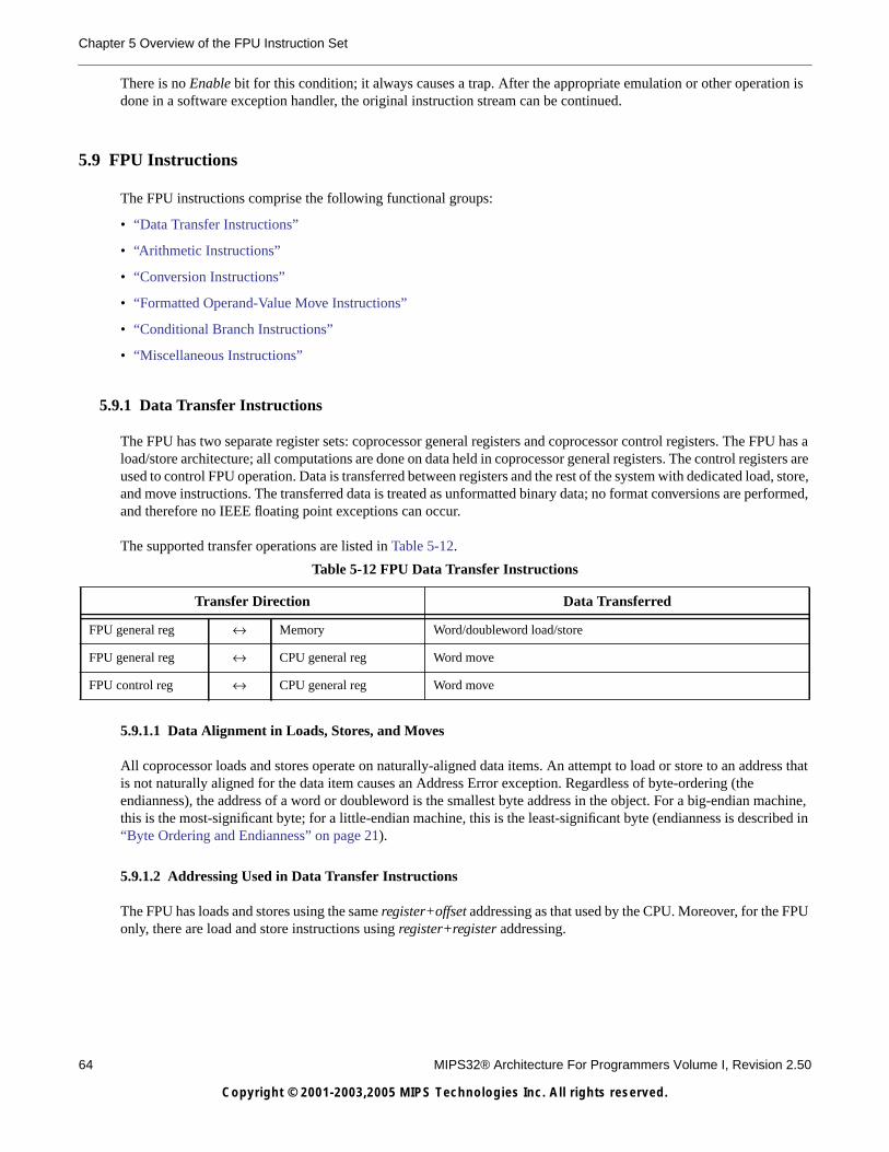
64 MIPS32® Architecture For Programmers Volume I, Revision 2.50
Copyright © 2001-2003,2005 MIPS Technologies Inc. All rights reserved.
Chapter 5 Overview of the FPU Instruction Set
There is no Enable bit for this condition; it always causes a trap. After the appropriate emulation or other operation isdone in a software exception handler, the original instruction stream can be continued.
5.9 FPU Instructions
The FPU instructions comprise the following functional groups:
• “Data Transfer Instructions”
• “Arithmetic Instructions”
• “Conversion Instructions”
• “Formatted Operand-Value Move Instructions”
• “Conditional Branch Instructions”
• “Miscellaneous Instructions”
5.9.1 Data Transfer Instructions
The FPU has two separate register sets: coprocessor general registers and coprocessor control registers. The FPU has aload/store architecture; all computations are done on data held in coprocessor general registers. The control registers areused to control FPU operation. Data is transferred between registers and the rest of the system with dedicated load, store,and move instructions. The transferred data is treated as unformatted binary data; no format conversions are performed,and therefore no IEEE floating point exceptions can occur.
The supported transfer operations are listed in Table 5-12.
5.9.1.1 Data Alignment in Loads, Stores, and Moves
All coprocessor loads and stores operate on naturally-aligned data items. An attempt to load or store to an address thatis not naturally aligned for the data item causes an Address Error exception. Regardless of byte-ordering (theendianness), the address of a word or doubleword is the smallest byte address in the object. For a big-endian machine,this is the most-significant byte; for a little-endian machine, this is the least-significant byte (endianness is described in“Byte Ordering and Endianness” on page 21).
5.9.1.2 Addressing Used in Data Transfer Instructions
The FPU has loads and stores using the same register+offset addressing as that used by the CPU. Moreover, for the FPUonly, there are load and store instructions using register+register addressing.
Table 5-12 FPU Data Transfer Instructions
Transfer Direction Data Transferred
FPU general reg ↔ Memory Word/doubleword load/store
FPU general reg ↔ CPU general reg Word move
FPU control reg ↔ CPU general reg Word move

5.9 FPU Instructions
MIPS32® Architecture For Programmers Volume I, Revision 2.50 65
Copyright © 2001-2003,2005 MIPS Technologies Inc. All rights reserved.
Tables 5-13 through 5-15 list the FPU data transfer instructions.
5.9.2 Arithmetic Instructions
Arithmetic instructions operate on formatted data values. The results of most floating point arithmetic operations meetthe IEEE standard specification for accuracy—a result is identical to an infinite-precision result that has been roundedto the specified format, using the current rounding mode. The rounded result differs from the exact result by less thanone unit in the least-significant place (ULP).
Table 5-13 FPU Loads and Stores Using Register+Offset Address Mode
Mnemonic Instruction Defined in MIPS ISA
LDC1 Load Doubleword to Floating Point MIPS32
LWC1 Load Word to Floating Point MIPS32
SDC1 Store Doubleword to Floating Point MIPS32
SWC1 Store Word to Floating Point MIPS32
Table 5-14 FPU Loads and Using Register+Register Address Mode
Mnemonic Instruction Defined in MIPS ISA
LDXC1 Load Doubleword Indexed to Floating Point MIPS64
MIPS32 Release 2
LUXC1 Load Doubleword Indexed Unaligned to Floating Point MIPS64
MIPS32 Release 2
LWXC1 Load Word Indexed to Floating PointMIPS64
MIPS32 Release 2
SDXC1 Store Doubleword Indexed to Floating Point MIPS64
MIPS32 Release 2
SUXC1 Store Doubleword Indexed Unaligned to Floating Point MIPS64
MIPS32 Release 2
SWXC1 Store Word Indexed to Floating PointMIPS64
MIPS32 Release 2
Table 5-15 FPU Move To and From Instructions
Mnemonic Instruction Defined in MIPS ISA
CFC1 Move Control Word From Floating Point MIPS32
CTC1 Move Control Word To Floating Point MIPS32
MFC1 Move Word From Floating Point MIPS32
MFHC1 Move Word from High Half of Floating Point Register MIPS32 Release 2
MTC1 Move Word To Floating Point MIPS32
MTHC1 Move Word to High Half of Floating Point Register MIPS32 Release 2

66 MIPS32® Architecture For Programmers Volume I, Revision 2.50
Copyright © 2001-2003,2005 MIPS Technologies Inc. All rights reserved.
Chapter 5 Overview of the FPU Instruction Set
FPU IEEE-approximate arithmetic operations are listed in Table 5-16.
Two operations, Reciprocal Approximation (RECIP) and Reciprocal Square Root Approximation (RSQRT), may be lessaccurate than the IEEE specification:
• The result of RECIP differs from the exact reciprocal by no more than one ULP.
• The result of RSQRT differs from the exact reciprocal square root by no more than two ULPs.
Within these error limits, the results of these instructions are implementation specific.
A list of FPU-approximate arithmetic operations is given in Table 5-17..
Four compound-operation instructions perform variations of multiply-accumulate—that is, multiply two operands,accumulate the result to a third operand, and produce a result. These instructions are listed in Table 5-18. The productis rounded according to the current rounding mode prior to the accumulation. This model meets the IEEE accuracyspecification; the result is numerically identical to an equivalent computation using multiply, add, subtract, or negateinstructions.
Table 5-16 FPU IEEE Arithmetic Operations
Mnemonic Instruction Defined in MIPS ISA
ABS.fmt Floating Point Absolute Value MIPS32
ABS.fmt (PS) Floating Point Absolute Value (Paired Single) MIPS64MIPS32 Release 2
ADD.fmt Floating Point Add MIPS32
ADD.fmt (PS) Floating Point Add (Paired Single) MIPS64MIPS32 Release 2
C.cond.fmt Floating Point Compare MIPS32
C.cond.fmt (PS) Floating Point Compare (Paired Single) MIPS64MIPS32 Release 2
DIV.fmt Floating Point Divide MIPS32
MUL.fmt Floating Point Multiply MIPS32
MUL.fmt (PS) Floating Point Multiply (Paired Single) MIPS64MIPS32 Release 2
NEG.fmt Floating Point Negate MIPS32
NEG.fmt (PS) Floating Point Negate (Paired Single) MIPS64MIPS32 Release 2
SQRT.fmt Floating Point Square Root MIPS32
SUB.fmt Floating Point Subtract MIPS32
SUB.fmt (PS) Floating Point Subtract (Paired Single) MIPS64MIPS32 Release 2
Table 5-17 FPU-Approximate Arithmetic Operations
Mnemonic Instruction Defined in MIPS ISA
RECIP.fmt Floating Point Reciprocal Approximation MIPS64MIPS32 Release 2
RSQRT.fmt Floating Point Reciprocal Square Root Approximation MIPS64MIPS32 Release 2

5.9 FPU Instructions
MIPS32® Architecture For Programmers Volume I, Revision 2.50 67
Copyright © 2001-2003,2005 MIPS Technologies Inc. All rights reserved.
Table 5-18 lists the FPU Multiply-Accumulate arithmetic operations.
5.9.3 Conversion Instructions
These instructions perform conversions between floating point and fixed point data types. Each instruction convertsvalues from a number of operand formats to a particular result format. Some conversion instructions use the roundingmode specified in the Floating Control/Status register (FCSR), while others specify the rounding mode directly. Table5-19 and Table 5-20 list the FPU conversion instructions according to their rounding mode.
Table 5-18 FPU Multiply-Accumulate Arithmetic Operations
Mnemonic Instruction Defined in MIPS ISA
MADD.fmt Floating Point Multiply Add MIPS64MIPS32 Release 2
MADD.fmt (PS) Floating Point Multiply Add (Paired Single) MIPS64MIPS32 Release 2
MSUB.fmt Floating Point Multiply Subtract MIPS64MIPS32 Release 2
MSUB.fmt (PS) Floating Point Multiply Subtract (Paired Single) MIPS64MIPS32 Release 2
NMADD.fmt Floating Point Negative Multiply Add MIPS64MIPS32 Release 2
NMADD.fmt (PS) Floating Point Negative Multiply Add (Paired Single) MIPS64MIPS32 Release 2
NMSUB.fmt Floating Point Negative Multiply Subtract MIPS64MIPS32 Release 2
NMSUB.fmt (PS) Floating Point Negative Multiply Subtract (Paired Single) MIPS64MIPS32 Release 2
Table 5-19 FPU Conversion Operations Using the FCSR Rounding Mode
Mnemonic Instruction Defined in MIPS ISA
CVT.D.fmt Floating Point Convert to Double Floating Point MIPS32
CVT.L.fmt Floating Point Convert to Long Fixed Point MIPS64MIPS32 Release 2
CVT.PS.S Floating Point Convert Pair to Paired Single MIPS64MIPS32 Release 2
CVT.S.fmt Floating Point Convert to Single Floating Point MIPS32
CVT.S.fmt (PL, PU) Floating Point Convert to Single Floating Point(Paired Lower, Paired Upper)
MIPS64MIPS32 Release 2
CVT.W.fmt Floating Point Convert to Word Fixed Point MIPS32
Table 5-20 FPU Conversion Operations Using a Directed Rounding Mode
Mnemonic Instruction Defined in MIPS ISA
CEIL.L.fmt Floating Point Ceiling to Long Fixed Point MIPS64MIPS32 Release 2
CEIL.W.fmt Floating Point Ceiling to Word Fixed Point MIPS32

68 MIPS32® Architecture For Programmers Volume I, Revision 2.50
Copyright © 2001-2003,2005 MIPS Technologies Inc. All rights reserved.
Chapter 5 Overview of the FPU Instruction Set
5.9.4 Formatted Operand-Value Move Instructions
These instructions all move formatted operand values among FPU general registers. A particular operand type must bemoved by the instruction that handles that type. There are three kinds of move instructions:
• Unconditional move
• Conditional move that tests an FPU true/false condition code
• Conditional move that tests a CPU general-purpose register against zero
Conditional move instructions operate in a way that may be unexpected. They always force the value in the destinationregister to become a value of the format specified in the instruction. If the destination register does not contain an operandof the specified format before the conditional move is executed, the contents become undefined. (For more information,see the individual descriptions of the conditional move instructions in Volume II.)
These instructions are listed in Tables Table 5-21 through Table 5-23.
FLOOR.L.fmt Floating Point Floor to Long Fixed Point MIPS64MIPS32 Release 2
FLOOR.W.fmt Floating Point Floor to Word Fixed Point MIPS32
ROUND.L.fmt Floating Point Round to Long Fixed Point MIPS64MIPS32 Release 2
ROUND.W.fmt Floating Point Round to Word Fixed Point MIPS32
TRUNC.L.fmt Floating Point Truncate to Long Fixed Point MIPS64MIPS32 Release 2
TRUNC.W.fmt Floating Point Truncate to Word Fixed Point MIPS32
Table 5-21 FPU Formatted Operand Move Instructions
Mnemonic Instruction Defined in MIPS ISA
MOV.fmt Floating Point Move MIPS32
MOV.fmt (PS) Floating Point Move (Paired Single) MIPS64MIPS32 Release 2
Table 5-22 FPU Conditional Move on True/False Instructions
Mnemonic Instruction Defined in MIPS ISA
MOVF.fmt Floating Point Move Conditional on FP False MIPS32
MOVF.fmt (PS) Floating Point Move Conditional on FP False(Paired Single)
MIPS64MIPS32 Release 2
MOVT.fmt Floating Point Move Conditional on FP True MIPS32
MOVT.fmt (PS) Floating Point Move Conditional on FP True(Paired Single)
MIPS64MIPS32 Release 2
Table 5-20 FPU Conversion Operations Using a Directed Rounding Mode
Mnemonic Instruction Defined in MIPS ISA

5.9 FPU Instructions
MIPS32® Architecture For Programmers Volume I, Revision 2.50 69
Copyright © 2001-2003,2005 MIPS Technologies Inc. All rights reserved.
5.9.5 Conditional Branch Instructions
The FPU has PC-relative conditional branch instructions that test condition codes set by FPU compare instructions(C.cond.fmt).
All branches have an architectural delay of one instruction. When a branch is taken, the instruction immediatelyfollowing the branch instruction is said to be in the branch delay slot, and it is executed before the branch to the targetinstruction takes place. Conditional branches come in two versions, depending upon how they handle an instruction inthe delay slot when the branch is not taken and execution falls through:
• Branch instructions execute the instruction in the delay slot.
• Branch likely instructions do not execute the instruction in the delay slot if the branch is not taken (they are said tonullify the instruction in the delay slot).
Although the Branch Likely instructions are included in this specification, software is strongly encouraged toavoid the use of the Branch Likely instructions, as they will be removed from a future revision of the MIPSArchitecture.
The MIPS32 Architecture defines eight condition codes for use in compare and branch instructions. For backwardcompatibility with previous revision of the ISA, condition code bit 0 and condition code bits 1 thru 7 are in discontiguousfields in FCSR.
Table 5-24 lists the conditional branch (branch and branch likely) FPU instructions; Table 5-25 lists the deprecatedconditional branch likely instructions.
Table 5-23 FPU Conditional Move on Zero/Nonzero Instructions
Mnemonic Instruction Defined in MIPS ISA
MOVN.fmt Floating Point Move Conditional on Nonzero MIPS32
MOVN.fmt (PS) Floating Point Move Conditional on Nonzero(Paired Single)
MIPS64MIPS32 Release 2
MOVZ.fmt Floating Point Move Conditional on Zero MIPS32
MOVZ.fmt (PS) Floating Point Move Conditional on Zero(Paired Single)
MIPS64MIPS32 Release 2
Table 5-24 FPU Conditional Branch Instructions
Mnemonic InstructionDefined in MIPS
ISA
BC1F Branch on FP False MIPS32
BC1T Branch on FP True MIPS32
Table 5-25 Deprecated FPU Conditional Branch Likely Instructions
Mnemonic InstructionDefined in MIPS
ISA
BC1FL Branch on FP False Likely MIPS32
BC1TL Branch on FP True Likely MIPS32

70 MIPS32® Architecture For Programmers Volume I, Revision 2.50
Copyright © 2001-2003,2005 MIPS Technologies Inc. All rights reserved.
Chapter 5 Overview of the FPU Instruction Set
5.9.6 Miscellaneous Instructions
The MIPS ISA defines various miscellaneous instructions that conditionally move one CPU general register to another,based on an FPU condition code. It also defines an instruction to align a misaligned pair of paired-single values(ALNV.PS) and a quartet of instructions that merge a pair of paired-single values (PLL.PS, PLU.PS, PUL.PS, PUU.PS).
Table 5-26 lists these conditional move instructions.
5.10 Valid Operands for FPU Instructions
The floating point unit arithmetic, conversion, and operand move instructions operate on formatted values with differentprecision and range limits and produce formatted values for results. Each representable value in each format has a binaryencoding that is read from or stored to memory. The fmt or fmt3 field of the instruction encodes the operand formatrequired for the instruction. A conversion instruction specifies the result type in the function field; the result of otheroperations is given in the same format as the operands. The encodings of the fmt and fmt3 field are shown in Table 5-27.
Table 5-26 CPU Conditional Move on FPU True/False Instructions
Mnemonic Instruction Defined in MIPS ISA
ALNV.PS FP Align Variable MIPS64MIPS32 Release 2
MOVN Move Conditional on FP False MIPS32
MOVZ Move Conditional on FP True MIPS32
PLL.PS Pair Lower Lower MIPS64MIPS32 Release 2
PLU.PS Pair Lower Upper MIPS64MIPS32 Release 2
PUL.PS Pair Upper Lower MIPS64MIPS32 Release 2
PUU.PS Pair Upper Upper MIPS64MIPS32 Release 2
Table 5-27 FPU Operand Format Field (fmt, fmt3) Encoding
fmt fmt3InstructionMnemonic
Size
Data TypeName Bits
0-15 - Reserved
16 0 S single 32 Floating point
17 1 D double 64 Floating point
18-19 2-3 Reserved
20 4 W word 32 Fixed point
21 5 L long 64 Fixed point
22 6 PS paired single 64 Floating point
23–31 7 Reserved

5.10 Valid Operands for FPU Instructions
MIPS32® Architecture For Programmers Volume I, Revision 2.50 71
Copyright © 2001-2003,2005 MIPS Technologies Inc. All rights reserved.
The result of an instruction using operand formats marked U in Table 5-28 is not currently specified by this architectureand causes a Reserved Instruction exception.
Table 5-28 Valid Formats for FPU Operations
Mnemonic Operation
Operand Fmt
COP1Function
Value
COP1Xop4
Value
Float Fixed
S DPS W L
ABS Absolute value • • • U U 5
ADD Add • • • U U 0
C.cond Floating Point compare • • • U U 48–63
CEIL.L,(CEIL.W)
Convert to longword (word) fixed point, roundtoward +∞ • • U U U 10 (14)
CVT.D Convert to double floating point • U U • • 33
CVT.L Convert to longword fixed point • • U U U 37
CVT.S Convert to single floating point U • U • • 32
CVT. PU, PL Convert to single floating point (paired upper, pairedlower) U U • U U 32, 40
CVT.W Convert to 32-bit fixed point • • U U U 36
DIV Divide • • U U U 3
FLOOR.L,(FLOOR.W)
Convert to longword (word) fixed point, roundtoward -∞ • • U U U 11 (15)
MADD Multiply-Add • • • U U 4
MOV Move Register • • • U U 6
MOVC FP Move conditional on condition • • • U U 17
MOVN FP Move conditional on GPR≠zero • • • U U 19
MOVZ FP Move conditional on GPR=zero • • • U U 18
MSUB Multiply-Subtract • • • U U 5
MUL Multiply • • • U U 2
NEG Negate • • • U U 7
NMADD Negative Multiply-Add • • • U U 6
NMSUB Negative Multiply-Subtract • • • U U 7
PLL, PLU, PUL,PUU
Pair (Lower Lower, Lower Upper, Upper Lower,Upper Upper) U U • U U 44-47
RECIP Reciprocal Approximation • • U U U 21
ROUND.L,(ROUND.W)
Convert to longword (word) fixed point, round tonearest/even • • U U U 8 (12)

72 MIPS32® Architecture For Programmers Volume I, Revision 2.50
Copyright © 2001-2003,2005 MIPS Technologies Inc. All rights reserved.
Chapter 5 Overview of the FPU Instruction Set
5.11 FPU Instruction Formats
An FPU instruction is a single 32-bit aligned word. FP instruction formats are shown in Figures 5-17 through 5-26.
In these figures, variables are labelled in lowercase, such as offset. Constants are labelled in uppercase, as are numerals.Following these figures, Table 5-29 explains the fields used in the instruction layouts. Note that the same field may havedifferent names in different instruction layouts.
The field name is mnemonic to the function of that field in the instruction layout. The opcode tables and the instructionencode discussion use the canonical field names: opcode, fmt, nd, tf, and function. The remaining fields are not used forinstruction encode.
RSQRT Reciprocal square root approximation • • U U U 22
SQRT Square Root • • U U U 4
SUB Subtract • • • U U 1
TRUNC.L,(TRUNC.W)
Convert to longword (word) fixed point, roundtoward zero • • U U U 9 (13)
Key: • − Valid. U − Unimplemented and causes Reserved Instruction Exception.
Table 5-28 Valid Formats for FPU Operations (Continued)
Mnemonic Operation
Operand Fmt
COP1Function
Value
COP1Xop4
Value
Float Fixed
S DPS W L

5.11 FPU Instruction Formats
MIPS32® Architecture For Programmers Volume I, Revision 2.50 73
Copyright © 2001-2003,2005 MIPS Technologies Inc. All rights reserved.
5.11.1 Implementation Note
When present, the destination FPR specifier may be in the fs, ft or fd field.
Figure 5-17 I-Type (Immediate) FPU Instruction Format
Figure 5-18 R-Type (Register) FPU Instruction Format
Figure 5-19 Register-Immediate FPU Instruction Format
Figure 5-20 Condition Code, Immediate FPU Instruction Format
Figure 5-21 Formatted FPU Compare Instruction Format
Figure 5-22 FP RegisterMove, Conditional Instruction Format
31 26 25 21 20 16 15 0
opcode base ft offset
6 5 5 16
Immediate: Load/Store using register + offset addressing
31 26 25 21 20 16 15 11 10 6 5 0
COP1 fmt ft fs fd function
6 5 5 5 5 6
Register: Two-register and Three-register formatted arithmetic operations
31 26 25 21 20 16 15 11 0
COP1 sub rt fs 0
6 5 5 5 11
Register Immediate: Data transfer, CPU ↔ FPU register
31 26 25 21 20 18 17 16 15 0
COP1 BCC1 cc nd tf offset
6 5 3 1 1 16
Condition Code, Immediate: Conditional branches on FPU cc using PC + offset
31 26 25 21 20 16 15 11 10 8 7 6 5 0
COP1 fmt ft fs cc 0 function
6 5 5 5 3 2 6
Register to Condition Code: Formatted FP compare
31 26 25 21 20 18 17 16 15 11 10 6 5 0
COP1 fmt cc 0 tf fs fd MOVCF
6 5 3 1 1 5 5 6
Condition Code, Register FP: FPU register move-conditional on FP, cc

74 MIPS32® Architecture For Programmers Volume I, Revision 2.50
Copyright © 2001-2003,2005 MIPS Technologies Inc. All rights reserved.
Chapter 5 Overview of the FPU Instruction Set
Figure 5-23 Four-Register Formatted Arithmetic FPU Instruction Format
Figure 5-24 Register Index FPU Instruction Format
Figure 5-25 Register Index Hint FPU Instruction Format
Figure 5-26 Condition Code, Register Integer FPU Instruction Format
31 26 25 21 20 16 15 11 10 6 5 0
COP1X fr ft fs fd op4 fmt3
6 5 5 5 5 3 3
Register-4: Four-register formatted arithmetic operations
31 26 25 21 20 16 15 11 10 6 5 0
COP1X base index 0 fd function
6 5 5 5 5 6
Register Index: Load and Store using register + register addressing
31 26 25 21 20 16 15 11 10 6 5 0
COP1X base index hint 0 PREFX
6 5 5 5 5 6
Register Index Hint: Prefetch using register + register addressing
31 26 25 21 20 18 17 16 15 11 10 6 5 0
SPECIAL rs cc 0 tf rd 0 MOVCI
6 5 3 1 1 5 5 6
Condition Code, Register Integer: CPU register move-conditional on FP, cc
Table 5-29 FPU Instruction Format Fields
Field Description
BC1 Branch Conditional instruction subcode (op=COP1).
base CPU register: base address for address calculations.
COP1 Coprocessor 1 primary opcode value in op field.
COP1X Coprocessor 1 eXtended primary opcode value in op field.
cc Condition Code specifier; for architectural levels prior to MIPS IV, this must be set to zero.
fd FPU register: destination (arithmetic, loads, move-to) or source (stores, move-from).
fmt Destination and/or operand type (format) specifier.
fr FPU register: source.
fs FPU register: source.
ft FPU register: source (for stores, arithmetic) or destination (for loads).
function Field specifying a function within a particular op operation code.

5.11 FPU Instruction Formats
MIPS32® Architecture For Programmers Volume I, Revision 2.50 75
Copyright © 2001-2003,2005 MIPS Technologies Inc. All rights reserved.
function:
op4 + fmt3
op4 is a 3-bit function field specifying a 4-register arithmetic operation for COP1X. fmt3 is a3-bit field specifying the format of the operands and destination. The combinations are shownas distinct instructions in the opcode tables.
hint Hint field made available to cache controller for prefetch operation.
index CPU register that holds the index address component for address calculations.
MOVC Value in function field for a conditional move. There is one value for the instruction whenop=COP1, another value for the instruction when op=SPECIAL.
nd Nullify delay. If set, the branch is Likely, and the delay slot instruction is not executed.
offset Signed offset field used in address calculations.
op Primary operation code (see COP1, COP1X, LWC1, SWC1, LDC1, SDC1, SPECIAL).
PREFX Value in function field for prefetch instruction when op=COP1X.
rd CPU register: destination.
rs CPU register: source.
rt CPU register: can be either source or destination.
SPECIAL SPECIAL primary opcode value in op field.
sub Operation subcode field for COP1 register immediate-mode instructions.
tf True/False. The condition from an FP compare that is tested for equality with the tf bit.
Table 5-29 FPU Instruction Format Fields (Continued)
Field Description

76 MIPS32® Architecture For Programmers Volume I, Revision 2.50
Copyright © 2001-2003,2005 MIPS Technologies Inc. All rights reserved.
Chapter 5 Overview of the FPU Instruction Set

MIPS32® Architecture For Programmers Volume I, Revision 2.50 77
Copyright © 2001-2003,2005 MIPS Technologies Inc. All rights reserved.
Appendix A
Instruction Bit Encodings
A.1 Instruction Encodings and Instruction Classes
Instruction encodings are presented in this section; field names are printed here and throughout the book in italics.
When encoding an instruction, the primary opcode field is encoded first. Most opcode values completely specify aninstruction that has an immediate value or offset.
Opcode values that do not specify an instruction instead specify an instruction class. Instructions within a class arefurther specified by values in other fields. For instance, opcode REGIMM specifies the immediate instruction class,which includes conditional branch and trap immediate instructions.
A.2 Instruction Bit Encoding Tables
This section provides various bit encoding tables for the instructions of the MIPS32® ISA.
Figure A-1 shows a sample encoding table and the instruction opcode field this table encodes. Bits 31..29 of the opcodefield are listed in the leftmost columns of the table. Bits 28..26 of the opcode field are listed along the topmost rows ofthe table. Both decimal and binary values are given, with the first three bits designating the row, and the last three bitsdesignating the column.
An instruction’s encoding is found at the intersection of a row (bits 31..29) and column (bits 28..26) value. For instance,the opcode value for the instruction labelled EX1 is 33 (decimal, row and column), or 011011 (binary). Similarly, theopcode value for EX2 is 64 (decimal), or 110100 (binary).

78 MIPS32® Architecture For Programmers Volume I, Revision 2.50
Copyright © 2001-2003,2005 MIPS Technologies Inc. All rights reserved.
Appendix A Instruction Bit Encodings
Tables A-2 through A-20 describe the encoding used for the MIPS32 ISA. Table A-1 describes the meaning of thesymbols used in the tables.
Table A-1 Symbols Used in the Instruction Encoding Tables
Symbol Meaning
∗ Operation or field codes marked with this symbol are reserved for future use. Executing such aninstruction must cause a Reserved Instruction Exception.
δ(Also italic field name.) Operation or field codes marked with this symbol denotes a field class.The instruction word must be further decoded by examining additional tables that show values foranother instruction field.
βOperation or field codes marked with this symbol represent a valid encoding for a higher-orderMIPS ISA level or a new revision of the Architecture. Executing such an instruction must cause aReserved Instruction Exception.
∇
Operation or field codes marked with this symbol represent instructions which were only legal if64-bit operations were enabled on implementations of Release 1 of the Architecture. In Release 2of the architecture, operation or field codes marked with this symbol represent instructions whichare legal if 64-bit floating point operations are enabled. In other cases, executing such aninstruction must cause a Reserved Instruction Exception (non-coprocessor encodings orcoprocessor instruction encodings for a coprocessor to which access is allowed) or a CoprocessorUnusable Exception (coprocessor instruction encodings for a coprocessor to which access is notallowed).
31 26 25 21 20 16 15 0
opcode rs rt immediate
6 5 5 16
opcode bits 28..26
0 1 2 3 4 5 6 7
bits 31..29 000 001 010 011 100 101 110 111
0 000
1 001
2 010
3 011 EX1
4 100
5 101
6 110 EX2
7 111
Decimal encoding ofopcode (28..26)
Binary encoding ofopcode (28..26)
Decimal encoding ofopcode (31..29)
Binary encoding ofopcode (31..29)
Figure A-1 Sample Bit Encoding Table

A.2 Instruction Bit Encoding Tables
MIPS32® Architecture For Programmers Volume I, Revision 2.50 79
Copyright © 2001-2003,2005 MIPS Technologies Inc. All rights reserved.
θ
Operation or field codes marked with this symbol are available to licensed MIPS partners. Toavoid multiple conflicting instruction definitions, MIPS Technologies will assist the partner inselecting appropriate encodings if requested by the partner. The partner is not required to consultwith MIPS Technologies when one of these encodings is used. If no instruction is encoded withthis value, executing such an instruction must cause a Reserved Instruction Exception (SPECIAL2encodings or coprocessor instruction encodings for a coprocessor to which access is allowed) ora Coprocessor Unusable Exception (coprocessor instruction encodings for a coprocessor to whichaccess is not allowed).
σField codes marked with this symbol represent an EJTAG support instruction and implementationof this encoding is optional for each implementation. If the encoding is not implemented,executing such an instruction must cause a Reserved Instruction Exception. If the encoding isimplemented, it must match the instruction encoding as shown in the table.
εOperation or field codes marked with this symbol are reserved for MIPS Application SpecificExtensions. If the ASE is not implemented, executing such an instruction must cause a ReservedInstruction Exception.
φ Operation or field codes marked with this symbol are obsolete and will be removed from a futurerevision of the MIPS32 ISA. Software should avoid using these operation or field codes.
⊕Operation or field codes marked with this symbol are valid for Release 2 implementations of thearchitecture. Executing such an instruction in a Release 1 implementation must cause a ReservedInstruction Exception.
Table A-2 MIPS32 Encoding of the Opcode Field
opcode bits 28..26
0 1 2 3 4 5 6 7
bits 31..29 000 001 010 011 100 101 110 111
0 000 SPECIAL δ REGIMM δ J JAL BEQ BNE BLEZ BGTZ
1 001 ADDI ADDIU SLTI SLTIU ANDI ORI XORI LUI
2 010 COP0 δ COP1 δ COP2 θδ COP1X1 δ
1. In Release 1 of the Architecture, the COP1X opcode was called COP3, and was available as another user-available coprocessor. InRelease 2 of the Architecture, a full 64-bit floating point unit is available with 32-bit CPUs, and the COP1X opcode is reserved forthat purpose on all Release 2 CPUs. 32-bit implementations of Release 1 of the architecture are strongly discouraged from usingthis opcode for a user-available coprocessor as doing so will limit the potential for an upgrade path to a 64-bit floating point unit.
BEQL φ BNEL φ BLEZL φ BGTZL φ
3 011 β β β β SPECIAL2 δ JALX ε ε SPECIAL32
δ⊕
2. Release 2 of the Architecture added the SPECIAL3 opcode. Implementations of Release 1 of the Architecture signaled a ReservedInstruction Exception for this opcode.
4 100 LB LH LWL LW LBU LHU LWR β5 101 SB SH SWL SW β β SWR CACHE
6 110 LL LWC1 LWC2 θ PREF β LDC1 LDC2 θ β7 111 SC SWC1 SWC2 θ * β SDC1 SDC2 θ β
Table A-1 Symbols Used in the Instruction Encoding Tables
Symbol Meaning

80 MIPS32® Architecture For Programmers Volume I, Revision 2.50
Copyright © 2001-2003,2005 MIPS Technologies Inc. All rights reserved.
Appendix A Instruction Bit Encodings
Table A-3 MIPS32 SPECIAL Opcode Encoding of Function Field
function bits 2..0
0 1 2 3 4 5 6 7
bits 5..3 000 001 010 011 100 101 110 111
0 000 SLL1
1. Specific encodings of the rt, rd, and sa fields are used to distinguish among the SLL, NOP, SSNOP and EHB functions.
MOVCI δ SRL δ SRA SLLV * SRLV δ SRAV
1 001 JR2
2. Specific encodings of the hint field are used to distinguish JR from JR.HB and JALR from JALR.HB
JALR2 MOVZ MOVN SYSCALL BREAK * SYNC
2 010 MFHI MTHI MFLO MTLO β * β β3 011 MULT MULTU DIV DIVU β β β β4 100 ADD ADDU SUB SUBU AND OR XOR NOR
5 101 * * SLT SLTU β β β β6 110 TGE TGEU TLT TLTU TEQ * TNE *
7 111 β * β β β * β β
Table A-4 MIPS32 REGIMM Encoding of rt Field
rt bits 18..16
0 1 2 3 4 5 6 7
bits 20..19 000 001 010 011 100 101 110 111
0 00 BLTZ BGEZ BLTZL φ BGEZL φ * * * *
1 01 TGEI TGEIU TLTI TLTIU TEQI * TNEI *
2 10 BLTZAL BGEZAL BLTZALL φ BGEZALL φ * * * *
3 11 * * * * * * * SYNCI ⊕
Table A-5 MIPS32 SPECIAL2 Encoding of Function Field
function bits 2..0
0 1 2 3 4 5 6 7
bits 5..3 000 001 010 011 100 101 110 111
0 000 MADD MADDU MUL θ MSUB MSUBU θ θ1 001 θ θ θ θ θ θ θ θ2 010 θ θ θ θ θ θ θ θ3 011 θ θ θ θ θ θ θ θ4 100 CLZ CLO θ θ β β θ θ5 101 θ θ θ θ θ θ θ θ6 110 θ θ θ θ θ θ θ θ7 111 θ θ θ θ θ θ θ SDBBP σ
Table A-6 MIPS32 SPECIAL31 Encoding of Function Field for Release 2 of the Architecture
function bits 2..0
0 1 2 3 4 5 6 7
bits 5..3 000 001 010 011 100 101 110 111
0 000 EXT ⊕ β β β INS ⊕ β β β1 001 * * * * * * * *
2 010 * * * * * * * *
3 011 * * * * * * * *
4 100 BSHFL ⊕δ * * * β * * *
5 101 * * * * * * * *
6 110 * * * * * * * *
7 111 * * * RDHWR ⊕ * * * *

A.2 Instruction Bit Encoding Tables
MIPS32® Architecture For Programmers Volume I, Revision 2.50 81
Copyright © 2001-2003,2005 MIPS Technologies Inc. All rights reserved.
1. Release 2 of the Architecture added the SPECIAL3 opcode. Implementations of Release 1 of the Architecture signaled a ReservedInstruction Exception for this opcode and all function field values shown above.
Table A-7 MIPS32 MOVCI Encoding of tf Bit
tf bit 16
0 1
MOVF MOVT
Table A-8 MIPS321 SRL Encoding of Shift/Rotate
1. Release 2 of the Architecture added theROTR instruction. Implementationsof Release 1 of the Architecture ig-nored bit 21 and treated the instruc-tion as an SRL
R bit 21
0 1
SRL ROTR
Table A-9 MIPS321 SRLV Encoding of Shift/Rotate
1. Release 2 of the Architecture added theROTRV instruction. Implementa-tions of Release 1 of the Architectureignored bit 6 and treated the instruc-tion as an SRLV
R bit 6
0 1
SRLV ROTRV
Table A-10 MIPS32 BSHFL Encoding of sa Field1
1. The sa field is sparsely decoded to identify the final instructions. Entries in this table with no mnemonic are reserved for future useby MIPS Technologies and may or may not cause a Reserved Instruction exception.
sa bits 8..6
0 1 2 3 4 5 6 7
bits 10..9 000 001 010 011 100 101 110 111
0 00 WSBH
1 01
2 10 SEB
3 11 SEH
Table A-11 MIPS32 COP0 Encoding of rs Field
rs bits 23..21
0 1 2 3 4 5 6 7
bits 25..24 000 001 010 011 100 101 110 111
0 00 MFC0 β * * MTC0 β * *
1 01 * * RDPGPR ⊕ MFMC01 δ⊕ * * WRPGPR ⊕ *
2 10C0 δ
3 11

82 MIPS32® Architecture For Programmers Volume I, Revision 2.50
Copyright © 2001-2003,2005 MIPS Technologies Inc. All rights reserved.
Appendix A Instruction Bit Encodings
1. Release 2 of the Architecture added the MFMC0 function, which is further decoded as the DI and EI instructions.
Table A-12 MIPS32 COP0 Encoding of Function Field When rs=CO
function bits 2..0
0 1 2 3 4 5 6 7
bits 5..3 000 001 010 011 100 101 110 111
0 000 * TLBR TLBWI * * * TLBWR *
1 001 TLBP * * * * * * *
2 010 * * * * * * * *
3 011 ERET * * * * * * DERET σ4 100 WAIT * * * * * * *
5 101 * * * * * * * *
6 110 * * * * * * * *
7 111 * * * * * * * *
Table A-13 MIPS32 COP1 Encoding of rs Field
rs bits 23..21
0 1 2 3 4 5 6 7
bits 25..24 000 001 010 011 100 101 110 111
0 00 MFC1 β CFC1 MFHC1 ⊕ MTC1 β CTC1 MTHC1 ⊕1 01 BC1 δ BC1ANY2 δε∇ BC1ANY4 δε∇ * * * * *
2 10 S δ D δ * * W δ L δ PS δ *
3 11 * * * * * * * *
Table A-14 MIPS32 COP1 Encoding of Function Field When rs=S
function bits 2..0
0 1 2 3 4 5 6 7
bits 5..3 000 001 010 011 100 101 110 111
0 000 ADD SUB MUL DIV SQRT ABS MOV NEG
1 001 ROUND.L ∇ TRUNC.L ∇ CEIL.L ∇ FLOOR.L ∇ ROUND.W TRUNC.W CEIL.W FLOOR.W
2 010 * MOVCF δ MOVZ MOVN * RECIP ∇ RSQRT ∇ *
3 011 * * * * RECIP2 ε∇ RECIP1 ε∇ RSQRT1 ε∇ RSQRT2 ε∇4 100 * CVT.D * * CVT.W CVT.L ∇ CVT.PS∇ *
5 101 * * * * * * * *
6 110 C.FCABS.F ε∇
C.UNCABS.UN ε∇
C.EQCABS.EQ ε∇
C.UEQCABS.UEQ ε∇
C.OLTCABS.OLT ε∇
C.ULTCABS.ULT ε∇
C.OLECABS.OLE ε∇
C.ULECABS.ULE ε∇
7 111 C.SFCABS.SF ε∇
C.NGLECABS.NGLE ε∇
C.SEQCABS.SEQ ε∇
C.NGLCABS.NGL ε∇
C.LTCABS.LT ε∇
C.NGECABS.NGE ε∇
C.LECABS.LE ε∇
C.NGTCABS.NGT ε∇

A.2 Instruction Bit Encoding Tables
MIPS32® Architecture For Programmers Volume I, Revision 2.50 83
Copyright © 2001-2003,2005 MIPS Technologies Inc. All rights reserved.
Table A-15 MIPS32 COP1 Encoding of Function Field When rs=D
function bits 2..0
0 1 2 3 4 5 6 7
bits 5..3 000 001 010 011 100 101 110 111
0 000 ADD SUB MUL DIV SQRT ABS MOV NEG
1 001 ROUND.L ∇ TRUNC.L ∇ CEIL.L ∇ FLOOR.L ∇ ROUND.W TRUNC.W CEIL.W FLOOR.W
2 010 * MOVCF δ MOVZ MOVN * RECIP ∇ RSQRT ∇ *
3 011 * * * * RECIP2 ε∇ RECIP1 ε∇ RSQRT1 ε∇ RSQRT2 ε∇4 100 CVT.S * * * CVT.W CVT.L ∇ * *
5 101 * * * * * * * *
6 110 C.FCABS.F ε∇
C.UNCABS.UN ε∇
C.EQCABS.EQ ε∇
C.UEQCABS.UEQ ε∇
C.OLTCABS.OLT ε∇
C.ULTCABS.ULT ε∇
C.OLECABS.OLE ε∇
C.ULECABS.ULE ε∇
7 111 C.SFCABS.SF ε∇
C.NGLECABS.NGLE ε∇
C.SEQCABS.SEQ ε∇
C.NGLCABS.NGL ε∇
C.LTCABS.LT ε∇
C.NGECABS.NGE ε∇
C.LECABS.LE ε∇
C.NGTCABS.NGT ε∇
Table A-16 MIPS32 COP1 Encoding of Function Field When rs=W or L1
1. Format type L is legal only if 64-bit floating point operations are enabled.
function bits 2..0
0 1 2 3 4 5 6 7
bits 5..3 000 001 010 011 100 101 110 111
0 000 * * * * * * * *
1 001 * * * * * * * *
2 010 * * * * * * * *
3 011 * * * * * * * *
4 100 CVT.S CVT.D * * * * CVT.PS.PW ε∇ *
5 101 * * * * * * * *
6 110 * * * * * * * *
7 111 * * * * * * * *
Table A-17 MIPS64 COP1 Encoding of Function Field When rs=PS1
1. Format type PS is legal only if 64-bit floating point operations are enabled.
function bits 2..0
0 1 2 3 4 5 6 7
bits 5..3 000 001 010 011 100 101 110 111
0 000 ADD ∇ SUB ∇ MUL ∇ * * ABS ∇ MOV ∇ NEG ∇1 001 * * * * * * * *
2 010 * MOVCF δ∇ MOVZ ∇ MOVN ∇ * * * *
3 011 ADDR ε∇ * MULR ε∇ * RECIP2 ε∇ RECIP1 ε∇ RSQRT1 ε∇ RSQRT2 ε∇4 100 CVT.S.PU ∇ * * * CVT.PW.PS ε∇ * * *
5 101 CVT.S.PL ∇ * * * PLL.PS ∇ PLU.PS ∇ PUL.PS ∇ PUU.PS ∇
6 110 C.F ∇CABS.F ε∇
C.UN ∇CABS.UN ε∇
C.EQ ∇CABS.EQ ε∇
C.UEQ ∇CABS.UEQ ε∇
C.OLT ∇CABS.OLT ε∇
C.ULT ∇CABS.ULT ε∇
C.OLE ∇CABS.OLE ε∇
C.ULE ∇CABS.ULE ε∇
7 111 C.SF ∇CABS.SF ε∇
C.NGLE ∇CABS.NGLEε∇
C.SEQ ∇CABS.SEQ ε∇
C.NGL ∇CABS.NGL ε∇
C.LT ∇CABS.LT ε∇
C.NGE ∇CABS.NGE ε∇
C.LE ∇CABS.LE ε∇
C.NGT ∇CABS.NGT ε∇
Table A-18 MIPS32 COP1 Encoding of tf Bit When rs=S, D, or PS, Function=MOVCF
tf bit 16
0 1
MOVF.fmt MOVT.fmt
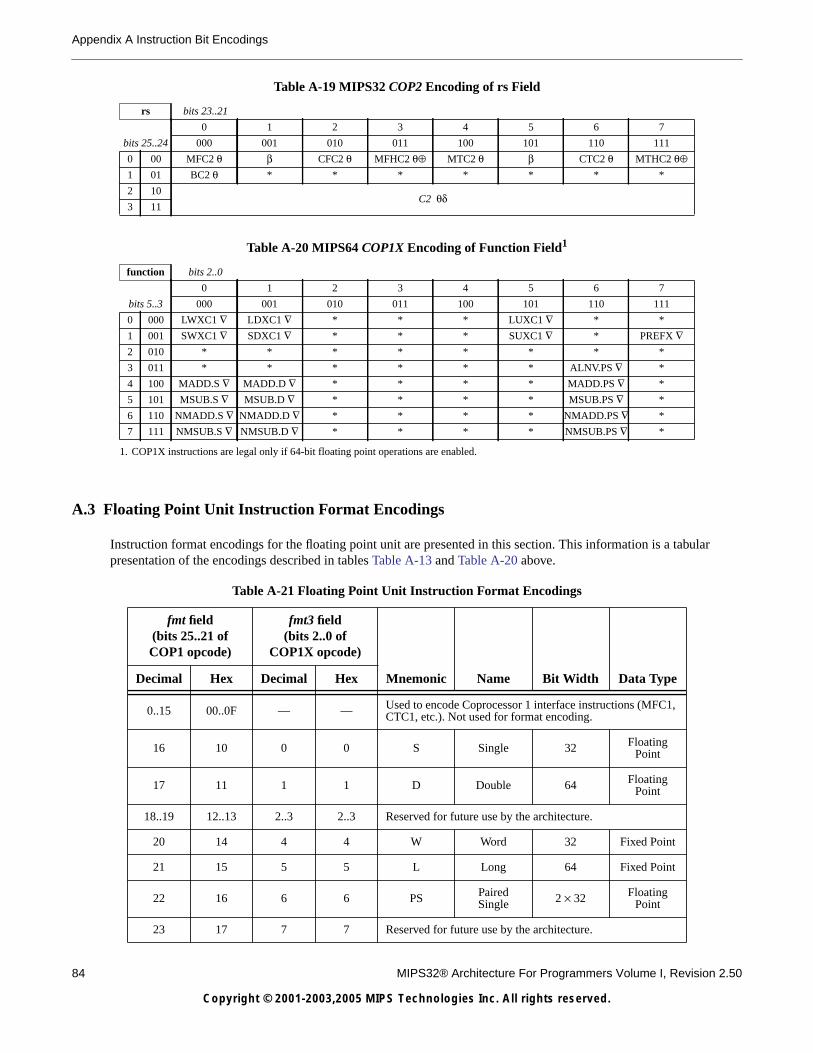
84 MIPS32® Architecture For Programmers Volume I, Revision 2.50
Copyright © 2001-2003,2005 MIPS Technologies Inc. All rights reserved.
Appendix A Instruction Bit Encodings
A.3 Floating Point Unit Instruction Format Encodings
Instruction format encodings for the floating point unit are presented in this section. This information is a tabularpresentation of the encodings described in tables Table A-13 and Table A-20 above.
Table A-19 MIPS32 COP2 Encoding of rs Field
rs bits 23..21
0 1 2 3 4 5 6 7
bits 25..24 000 001 010 011 100 101 110 111
0 00 MFC2 θ β CFC2 θ MFHC2 θ⊕ MTC2 θ β CTC2 θ MTHC2 θ⊕1 01 BC2 θ * * * * * * *
2 10C2 θδ
3 11
Table A-20 MIPS64 COP1X Encoding of Function Field1
1. COP1X instructions are legal only if 64-bit floating point operations are enabled.
function bits 2..0
0 1 2 3 4 5 6 7
bits 5..3 000 001 010 011 100 101 110 111
0 000 LWXC1 ∇ LDXC1 ∇ * * * LUXC1 ∇ * *
1 001 SWXC1 ∇ SDXC1 ∇ * * * SUXC1 ∇ * PREFX ∇2 010 * * * * * * * *
3 011 * * * * * * ALNV.PS ∇ *
4 100 MADD.S ∇ MADD.D ∇ * * * * MADD.PS ∇ *
5 101 MSUB.S ∇ MSUB.D ∇ * * * * MSUB.PS ∇ *
6 110 NMADD.S ∇ NMADD.D ∇ * * * * NMADD.PS ∇ *
7 111 NMSUB.S ∇ NMSUB.D ∇ * * * * NMSUB.PS ∇ *
Table A-21 Floating Point Unit Instruction Format Encodings
fmt field(bits 25..21 ofCOP1 opcode)
fmt3 field(bits 2..0 of
COP1X opcode)
Mnemonic Name Bit Width Data TypeDecimal Hex Decimal Hex
0..15 00..0F — — Used to encode Coprocessor 1 interface instructions (MFC1,CTC1, etc.). Not used for format encoding.
16 10 0 0 S Single 32 FloatingPoint
17 11 1 1 D Double 64 FloatingPoint
18..19 12..13 2..3 2..3 Reserved for future use by the architecture.
20 14 4 4 W Word 32 Fixed Point
21 15 5 5 L Long 64 Fixed Point
22 16 6 6 PS PairedSingle 2 × 32 Floating
Point
23 17 7 7 Reserved for future use by the architecture.

A.3 Floating Point Unit Instruction Format Encodings
MIPS32® Architecture For Programmers Volume I, Revision 2.50 85
Copyright © 2001-2003,2005 MIPS Technologies Inc. All rights reserved.
24..31 18..1F — — Reserved for future use by the architecture. Not available forfmt3 encoding.
Table A-21 Floating Point Unit Instruction Format Encodings
fmt field(bits 25..21 ofCOP1 opcode)
fmt3 field(bits 2..0 of
COP1X opcode)
Mnemonic Name Bit Width Data TypeDecimal Hex Decimal Hex

86 MIPS32® Architecture For Programmers Volume I, Revision 2.50
Copyright © 2001-2003,2005 MIPS Technologies Inc. All rights reserved.
Appendix A Instruction Bit Encodings
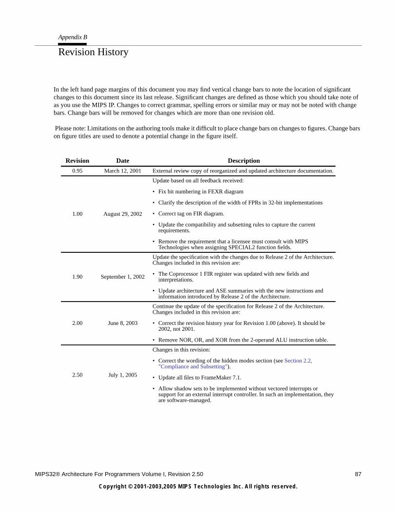
MIPS32® Architecture For Programmers Volume I, Revision 2.50 87
Copyright © 2001-2003,2005 MIPS Technologies Inc. All rights reserved.
Appendix B
Revision History
In the left hand page margins of this document you may find vertical change bars to note the location of significantchanges to this document since its last release. Significant changes are defined as those which you should take note ofas you use the MIPS IP. Changes to correct grammar, spelling errors or similar may or may not be noted with changebars. Change bars will be removed for changes which are more than one revision old.
Please note: Limitations on the authoring tools make it difficult to place change bars on changes to figures. Change barson figure titles are used to denote a potential change in the figure itself.
Revision Date Description
0.95 March 12, 2001 External review copy of reorganized and updated architecture documentation.
1.00 August 29, 2002
Update based on all feedback received:
• Fix bit numbering in FEXR diagram
• Clarify the description of the width of FPRs in 32-bit implementations
• Correct tag on FIR diagram.
• Update the compatibility and subsetting rules to capture the currentrequirements.
• Remove the requirement that a licensee must consult with MIPSTechnologies when assigning SPECIAL2 function fields.
1.90 September 1, 2002
Update the specification with the changes due to Release 2 of the Architecture.Changes included in this revision are:
• The Coprocessor 1 FIR register was updated with new fields andinterpretations.
• Update architecture and ASE summaries with the new instructions andinformation introduced by Release 2 of the Architecture.
2.00 June 8, 2003
Continue the update of the specification for Release 2 of the Architecture.Changes included in this revision are:
• Correct the revision history year for Revision 1.00 (above). It should be2002, not 2001.
• Remove NOR, OR, and XOR from the 2-operand ALU instruction table.
2.50 July 1, 2005
Changes in this revision:
• Correct the wording of the hidden modes section (see Section 2.2,"Compliance and Subsetting").
• Update all files to FrameMaker 7.1.
• Allow shadow sets to be implemented without vectored interrupts orsupport for an external interrupt controller. In such an implementation, theyare software-managed.