Embed Size (px)
Citation preview

m DEPARTMENT OF LABOR AND INDUSTRY CONSTRUCTION CODES AND LICENSING
Minnesota Residential Energy Code
3152022
Steve Shold ndash Construction Code Representative Certified Building Official ICC Residential Energy InspectorPlans Examiner 651-284-5312 stevesholdstatemnus | wwwdlimngov
1
Agenda
Topics
bull What is the purpose of the Energy Code
bull Overview of the 2015 MN Residential Energy Code sections
bull What are the buildingrsquos energy systems
bull What is required for a plan review
bull Field inspections What to look for and when
bull Questions
3152022 2
Presentation
Things to note bull Slides may not include the entire code section or all exceptions Always defer to the actual code
text
bull Images in the presentation are intended to convey a point and may not necessarily represent compliance with the code
bull Always defer to the Building Official of the local Authority Having Jurisdiction for help with interpretation
bull This is not an exhaustive review of the MN Residential Energy Code in its entirety
3152022 3
Energy Code Purpose amp Intent
Purpose of the Energy Code - ICC
bull 2018 IECC (RE) Scope amp General Requirements
R1013 Intent This code shall regulate the design and construction of buildings for the effective use and conservation of energy over the useful life of each building This code is intended to provide flexibility to permit the use of innovative approaches and techniques to achieve this objective This code is not intended to abridge safety health or environmental requirements contained in other applicable codes or ordinances
3152022 5
Purpose of the Energy Code - MN
bull 2015 MN Residential Energy Code 13220015 Administration amp Purpose
Subp 2 Purpose The purpose of this chapter is to establish a minimum code of standards for the construction reconstruction alteration and repair of residential buildings governing matters including design and construction standards regarding heat loss control illumination and climate control pursuant to Minnesota Statutes Sections 326B101 326B106 and 326B13
3152022 6
Purpose of the Energy Code
bull This will impact
bull The durability of the building (moisture issues)
bull Health of occupants (air quality)
bull Operational cost savings over the life of the building
3152022 7
Purpose of the Energy Code
bull Structural vs Energy
bull Energy always yields to structural requirements if you cant get both
VS
3152022 8
reg INTERNATIONAL ENERGY CONSERVATION CODE
Overview of the Energy Code
3152022 Optional Tagline Goes Here | wwwdlimngov 9
2020
) ~ ~ m DEAIHMEH1 OF Jiid lAIORAHOIHOUSHIY
MN Energy Code
MN Energy Code ndash Residential and Commercial provisions
bull Residential Energy Code - rule chapter 1322
bull Based on the 2012 IECC with MN amendments
bull Pages R1 ndash R44 (front of green book)
2020
MINNESOTA
)~~ m J iid lAIOR AHOIHOUSIIIY
___ __ - Energy Standard
for Buildings Except LowbullRise
Residential Buildings
MN Energy Code
MN Energy Code ndash Residential and Commercial provisions
bull Commercial Energy Code - rule chapter 1323
bull Based (mostly) on the 2018 IECC with MN amendments
bull Pages C1 ndash C122 (middle of green book)
bull 6 chapters
bull Also contains ANSIASHRAEIES 901-2016 essentially another CE Code path option
bull Pages 1-380 (last part of book)
TABLE OF CONTENTS
CH-PTIR I SCOPE AXD ADlIDlSTR- TIOlt ~ krtd) l
010 M1ESOTA BUILDIXC CODE ADID1S11lATO- bullbull bullbull bullbull bullbull bull bullbull bullbullbullbull bullbull bull bull 3
= 13000010 AdmziusntHD
13000021 Title
1300 0030 Putpow aod Apphca1100
130000W Scope
130000SO ChaplttS ofMmnHOU Sute Bualdmg Code 4
13000060 Ophana1Admumt1abon
1]00 0070 DtfimtlOGS
13000080 Code Adoptlaa and~
13000090 Depanmem orBudding Safey S 13000110 Duties and POllmiddoten oBuildmg Official bull S
13000120 P~lDlll
13000130 Comtr00oaDoaantms
1300 0 140 Violabom 10
13000150 Violampuom Pemlty 10 ll00J)l60 F~ 10
1l000170 StopWlaquokOnier 11
IJOO0IIO UmaitBU1ldulgl01 Sttutturu 11
1300 0190 Teqorary Snctutts aad Ues 12 IJ000210 Impec11om bullbull bull 12
1300021 S Plumbing bull 13
IJOOJ)LltI Cerufic1u-ofOccupaoc-y 14
13000215 Mamknalltt U
13000230 Board ofAppuls 14 130002-laquol DisclaimerClause bullbullbull 1S
13000HO ~-cr_lhry lS
00 ~IDUOT- PRO 1SJ OXS TO THpound ID~UOTA STATE BlIlDLC CODE (L~CLllgtCG RADO~) 17
1303 1000 Tide
13031100 ~
1303 1200 Rrstroomfaohtinw Pubhc AccommodabODt
17
17
1303 1300 SpaceforCommulffVam 17
13031400 Auiomat1eGangegtootOpnwig Syuems 17
17
13031600 FootingdegPchfor f r01t 18
18
18 18
bull bullbullbullbullbullbullbullbull 19
20
20
~01~ IL~LSOTA RESIDDTIU D LRGY COD[ J
1112 CKIIO AdoptlOD oflaitmabOOal Eaftv ComfflbCG Cock (IECC) by ~fttrlaquoe 23
IJHIOl5 Aduunntnt10Dandwpow 23
132 0030 Rffuffltts to Ocbesmiddot lmemabooal Cock CowaJ ~CC) Codtt 1J
1322 OG40 Admmutntn~ ~ Cntnu 13
132 0100 Admmamitmo fm Reu~~I ~bull 1J
1320103 ComaucuocDocumenu 1
RlO I 0-1 R02 Otaer1ilDdimt1om RJO I Chma1eloaes 11
R302 DesignCoodinom RJOJ Matenals Syuems and Eqwpment 1
R401 deg R402 Bwldulg TbtnnaJ ampntlope RAOJ s RO E1laquotncaJ PCMff IOd Ltplwig Sys1ems
(ModbullY) s R40gt Sllilllla~ Pttf~ Ahemata-e
(Pirsfonnmce) s
Cgtplt- ~ftttGCNSlaiwslh O O ~LSOTA RESIDDTlL COD[ bullbullbullbullbullbullbull 61
61
bullbull 6 1
2015 MINNESOTA RESIDENTIAL ElTERGY CODE 23
Section
13220010 Adoption oflntemational Energy
13220015
1322000
13_20040
13220100
13220103
R201
R202
R301
R302
R303
R401
R402
R403
R404
Chapter 5
Conse1vation Code (IECC) by Reference 23
Adminisumiddotation and Purpo e
References to Other International Code Council (ICC) Codes
Administrative Procedure C1ite1ia
Achninisu-ation for Residential Energy
Consu11ction Documents
General
General Definition
Climate Zones
De ign Conditions
Mate1ial System and Equipment
General
Building The1mal Envelope
Sy terns
Electrical Power and Lighting Sy terns
23
23
23
24
25
2 -
27
42
42
43
43
48
(Mandato1y) 54
Simulated Perfo1mance Alternative (Pe1fo1mance) 54
Referenced Standards 59
2020 MIN~ ESOTA RESIDE1 TIAL CODE 61
N M N M N M N M N M N M N M N M N M N M N M N M N M N M N M N M N M N M N M N M N M N M N M N M N M N M N M N M N M N M N M N M N M N M N M 123152022
- I -
~ fflil DEPARTMENT OF ~ ~ LABOR AND INDUSTRY
2015 MINNESOTA RESIDENTIAL ElTERGY CODE 23
Section
13220010 Adoption oflntemational Energy Conse1vation Code (IECC) by Reference 23
13220015 Adminisumiddotation and Purpo e 23
1322000 References to Other International Code Council (ICC) Codes 23
13_20040 Administrative Procedure C1ite1ia 23
13220100 Adminisu-ation for Residential Energy 23
N M N M N M N M N M N M N M N M N M N M N M N M N M N
13220103 Construction Docmnents 24 ~
R201
R202
R301
R302
R303
R401
R402
R403
R404
Chapter 5
General 25
General Definition 2 -
Climate Zones 27
De ign Conditions 42
Material System and Equipment 42
General 43
Building Thermal Envelope 43
Sy terns 48
Elecuical Power and Lighting Sy terns (Mandato1y) 54
Simulated Performance Alternative (Pe1fo1mance) 54
Referenced Standards 59
2020 MIN~ ESOTA RESIDE1 TIAL CODE 61
M N M N M N M N M N M N M N M N M N M N M N M N M N M N M N M N M N M N M N M N M 13
Administration
Energy Sections
3152022 Residential Building
- I -
~ fflil DEPARTMENT OF ~ ~ LABOR AND INDUSTRY
2015 MINNESOTA RESIDENTIAL ElTERGY CODE 23
Section
J-322__----_ d pti_____tcrurrtionlt lRr= ~
Conse1vation Code (IECC) by Reference 23
13220015 Adminism1tion and Purpo e 23
1322000 References to Other International Code Council (ICC) Codes 23
13_20040 Administrative Procedure C1ite1ia 23
l ~ 2 100 -~dmini trati n for R middot idcntia1 11irg middot 23
N M N M N M N M N M N M N M N M N M N M N M N M N M N
13220103 Construction Docmnents 24 ~
R201
R202
R301
R302
R303
R401
R402
R403
R404
Chapter 5
General 25
General Definition 2 -
Climate Zones 27
De ign Conditions 42
Material System and Equipment 42
General 43
Building Thermal Envelope 43
Sy terns 48
Elecnical Power and Lighting Sy terns (Mandato1y) 54
Simulated Performance Alternative (Pe1fo1mance) 54
Referenced Standards 59
2020 MIN~ ESOTA RESIDE1 TIAL CODE 61
M N M N M N M N M N M N M N M N M N M N M N M N M N M N M N M N M N M N M N M N M 14
Administration
3152022
ubp 2 Mandator chapter Chapter (RE to
the Re idential Pro i ion of the 01 IECC shall be ac mmshyN isterec 1y any nnmicipality that ha ado )tecl the Jfinncsotlt N _middotrare Builr iw ori c except a qualified b applicable pro ishy
in Minne ota Rule Chapter 1 00 and a a111ended b hapter
N
2015 MINNESOTA RESIDENTIAL ~ M
ElTERGY CODE 23 N
Section
--J---J-U-- d pti - ___tcrurrtioult lRr= ~
Conse1vation Code (IECC) by Reference 23
13220015 Adminisumiddotation and Purpo e 23
1322000 References to Other International Code Council (ICC) Codes 23
13_20040 Administrative Procedure C1ite1ia 23
l ~ 2 100 -~dmini trati u for R middot idcntia1 uirg middot 23
13220103 Consu11ction Documents 24
R201
R202
R301
R302
R303
R401
R402
R403
R404
Chapter 5
General 25
General Definition 2 -
Climate Zones 27
De ign Conditions 42
Mate1ial System and Equipment 42
General 43
Building The1mal Envelope 43
Sy terns 48
Elecuical Power and Lighting Sy terns (Mandato1y) 54
Simulated Perfo1mance Alternative (Pe1fo1mance) 54
Referenced Standards 59
2020 MIN~ESOTA RESIDE1 TIAL CODE 61
M N M N M N M N M N M N M N M N M N M N M N M N M N M N M N M N M N M N M N M N M N M N M N M N M N M N M N M N M N M N M N M N M 15
MR 13220010 Subp 2
3152022
Subpart 1 Administration In addition to the application of ~ Minnesota Rules Chapter 1300 the aonmistiatiYe rec uire- M
111enh in tlus part shall apph-
~ Subp 2 Scope Thi code applie to 1es1dential b 1ilc lllL and M as ociated stelllS and equipment a defined in the Re idenshyN M tial Pro i ions of the 01 IEC
N
2015 MINNESOTA RESIDENTIAL ~ ENERGY CODE 23 ~
Section
J-322________- d pti_____tcrurrtionlt lRr= ~
Conse1vation Code (IECC) by Reference 23
13220015 Adminisumiddotation and Purpo e 23
1322000 References to Other International Code Council (ICC) Codes 23
13_20040 Administrative Procedure C1ite1ia 23
l ~ -2 100 -~dmini trati u for R middot idcutia1 11irg middot 23
13220103 Construction Documents 24
R201
R202
R301
R302
R303
R401
R402
R403
R404
Chapter 5
General 25
General Definition 2 -
Climate Zones 27
De ign Conditions 42
Mate1ial System and Equipment 42
General 43
Building The1mal Envelope 43
Sy terns 48
Elecuical Power and Lighting Sy terns (Mandato1y) 54
Simulated Perfo1mance Alternative (Pe1fo1mance) 54
Referenced Standards 59
2020 Mll~ESOTA RESIDE1 TIAL CODE 61
M N M N M N M N M N M N M N M N M N M N M N M N M N M N M N M N M N M N M N M N M N M N M N M N M N M N M N M N M N M N M N M N M 16
MR 13220100 Subp 1 amp 2
3152022
RESIDENTIAL BUILDING For this code include detached one- and two-famil dvellings and multiple singleshyfamil dwellings townhouses as ell as Group R-2 R- and R-4 buildinos three tories or less in height abo e grade plane
17
Scoping
bull RE Chapter 2 Definitions
httpswwwphillyaptrentalscomblogwhat-makes-a-good-apartment-building
Subp 3 Applicability
A Aclclition alteration reno ations or repair cldishytions alteration renovations or repair to an exi ting building building y tern or portion of a buildindeg hall conf01m to the provi ion of thi code a they relate to ne on truction without requiring the unaltered porshytion of the e i ting building or building tern to comshyply with this code ddition alterations reno ations or repair hall not create an un afe or hazardou condishytion or o erload exi ting building ystem An addition hall comply v ith thi code if the addition alone comshy
plie or if the exi ting building and addition compl ith thi code as a single building Attic insulation
shall not be in talled unless acces ible attic bypas e ha e been ealed An attic bypa i an air pa agev ay between a conditioned pa e and an unconditioned attic
N
2015 MINNESOTA RESIDENTIAL ~ ENERGY CODE 23 ~
Section
13220010 Adoption oflntemational Energy Conse1vation Code (IECC) by Reference 23
13220015 Adminisumiddotation and Purpo e 23
1322000 References to Other International Code Council (ICC) Codes 23
13_20040 Administrative Procedure C1ite1ia 23
13220103 Consu11ction Documents 24
M N M N M N M N M N M N M N M N M N M N M N M N
18
MR 13220100 Subp 3A
httpsuncleravewordpresscom20200221jumble-spoiler-02-21-20
3152022
Exceptions The follov ing are ex epted from this pai1 provided the energ use of the buildindeg i not in rea ed
1 tonu windomiddot in talled over e i ting middotinshydow
Gla onl replacements in an exi ting and frame
Exi ting eiling wall or floor cavities expo ed during onstru tion promiddotided that the e cavities are filled vith insulation
Constn1 tion where the exi ting roof middotall or floor cavi middot not expo ed
- Reroofing and re iding lt
Repla ement of existing door that eparate conditioned pace from the exterior do not require the in tallation of a middotestibnle or revolvindeg door provided that an exi ting ve -tibule tha t epaimiddotate a conditioned spa e from the exterior hall not be removed
Alterations that repla e le s than -o percent of the luminaire in a pace provided that the alterations do not in rea e the installed inteshyrior lighting power
8 Alterations that replace onl the bulb and balshylast within the exi ting luminaire in a spa e promiddotided that the alteration doe not increa e the installed interior lighting power
In ulation R-value air banier and vapor retarder requirement are not applicable to exi ting foundatio rawl spa e wall and ba ements in exi ting dmiddotellings or dwelling units middothen the alteration or repair require a pennit if the original dwelling or dwelling unit permit a i ued before June I _009
Applicability - Exceptions
bull MN Rules 13220100 Subp 3 A
bull Exceptionshellip
B Low energy building The f ollm ing building or N
ponion thereof eparated from the remainder of the N
building by building the1mal eu elope as ernblie corn- N
pl ing ith thi code are exem t from the building N
thenna enmiddotdope promiddotisions o this code
1 tho e with a peak de ign rate of energ u a0 e le than Btuh middot ft 10- m2 or 10 v a 10 of floor area for space conditioning N
purpo e and
tho e that do not contain conditioned pace N
N
2015 MINNESOTA RESIDENTIAL ~ ENERGY CODE 23 ~
Section
13220010 Adoption oflntemational Energy Conse1vation Code (IECC) by Reference 23
13220015 Adminisumiddotation and Purpo e 23
1322000 References to Other International Code Council (ICC) Codes 23
13_20040 Administrative Procedure C1ite1ia 23
-----ii l ~ 2 100 -~dmini trati u for R middot idcutia1 ucrg middot 23
13220103 Construction Documents 24
R201
R202
R301
R302
General 25
General Definition 2 -
Climate Zones 27
De ign Conditions 42
M N M N M N M N M N M N M N M N M N M N M N M N M N M N M N M N M N M
3152022 20
MR 13220100 Subp 3B C D
httpshomeownersinsurancecovernetdetached-garages
httpswwwpinterestcompin559853797425326537
Paths
bull MN Residential Energy Code
bull Prescriptive ndash R402 amp R403
bull R-value
bull U-Factor Alternative
bull Total UA Alternative
bull Simulated Performance Alternative (Performance) ndash R405
3152022 Optional Tagline Goes Here | wwwdlimngov 21
Paths
bull MN Residential Energy Code
bull Prescriptive
bull R-value
3152022 Optional Tagline Goes Here | wwwdlimngov 22
3
R4021 1 INSULATION AND FENESTRATION REQUIREMENTS BYCOMPONENT8
CLIMATE FENESTRATION SKYLIGHTb GLAZED CEIUNGi WOOD MASS FLOOR BASEMEN-rlti SLABd CRAWL ZONE U-FACTORb U-FACTOR FENESTRATION R-VALUE FRAME WALL R-VALUE WALL R-VALUE SPACEc
SHGcbe WALL R-VALUEigh R-VALUE ampDEPTH WALL R-VALUE1 R-VALUE
6 032 0 NR 49 20 13+ 1 20 3oe 15 10 1 -
3 - ft
032 0 5 rn 49 21 1921 38 15 10 1 -5 ft
For SI 1 foot = 3048 uuu a R-values are minimums U-fa tors and SHGC are maximums When insulation is installed in a cavity that is less than the label or design thickness of the
insulation the installed R-middotalue of the insulation shall not be less than the R-value specified in the table b The fenestration U-factor column excludes skylights The SHGC column applies to all glazed fenestration c See Section R402 28 d Insulation R-values for heated slabs shall be installed to the depth indicated or to the top of the footing whichever is less e Or insulation sufficient to fill the framing cavity R-19 minimum f First value is avity insulation second is ontinuous insulation or insulated siding so bullmiddot13+ middotmiddot means R-13 cavity insulation plus R-5 ontinuous insulation or
insulated siding If stru tmal sheathing covers 40 percent or less of the exterior continuous insulation R-value shall be permitted to be reduced by no more than R-3 in the locations where structural sheathing is used to maintain a consistent total sheathing thickness
g The second R-value applies when more than half the insulation is on the interior of the mass wall h When using log-type onstru tion for thenual mass Valls the folloving applies
l) a minimum of a -inch diameter log shall be used and
- ) the -value of fenestration products shall be 029 overall on average or better
1 See ection 40- 2 8 A minimum R-19 cavity insulation is required in wood foundation Yalls J Roopound eiling assemblies shall have a minimum 6-inch energy heel 3152022 Optional Tagline Goes Here | wwwdlimngov 2
Prescriptive Path ndash R-value
CLIMATE FENESTRATION ZONE U-FACTORb
6 032
032
TABLE R4021 1 INSULATION AND FENESTRATION REQUIREMENTS BYCOMPONENT3
SKYLIGHTb GLAZED CEIUNGi WOOD MASS FLOOR BASEMEN-C U-FACTOR FENESTRATION R-VALUE FRAME WALL R-VALUE
SHGcbe WALL R-VALUEigh R-VALUE1
0 5 NR 49 _o_ 13+ 1 _0 30
0 5 fR 49 _1 19_l 38
R40212 R- aloe computation In ulation material used in la ers uch a framing ca ity in ulation and in ulatindeg heathing hall be ummed to compute the component Rshyalue Tue manufa nu-er settled R-value hall be u ed
for blo n insulation Conuutecl R-Yalue gthall not include an R-middotalue or ot 1er )lll c mg matenab or air
WALL R-VALUE
15
15
SLABd CRAWL R-VALUE SPACEc amp DEPTH WALL
R-VALUE
10 1
35 ft
10 1-5 ft
Prescriptive Path ndash R-value
3152022 24
Paths
bull MN Residential Energy Code
bull Prescriptive
bull R-value
bull U-Factor Alternative ndash R40213
3152022 25
R402l3 G-factor alternath e An a ernbl factor equal to or les than that pecified R O 1 hall be permitted a an alte1nati e to the R-
alue in Tabl R O 11
TABLE R40213 EQU IVALENT U-FACTORSa
CLIMATE FENESTRATION SKYLIGHT CEILING FRAME MASS WALL ZONE U-FACTOR U-FACTOR U-FACTOR
WALL U-FACTORb U-FACTOR
1 0 0 I 0 19- 040 -
Ia1me - me-t
6 0060
and 8 032 0026 00 8 00 a onfenestration U-factors shall be obtained from measurement alculation or an approved source
FLOOR BASEMENT CRAWL
U-FACTOR WALL SPACE WALL
U-FACTOR U-FACTOR
0 064 6 --
0 06-t 0 360 04--
0 091 0 136
006
0033
00_8 0050
b When more than half the insulation is on the inte1~or the mass middotall -factors shall be a maximum of 0 1 in Climate Zone 1 0 14 in Climate Zone - middot 0 1 m Climate Zone 3 008 in Climate Zone 4 except Marine 006 - in Climate Zone 5 and Marine 4 and 00 in Climate Zones 6 through 8
c Basement wall U-fa ctor of 0360 in warm-humid locations as defined by Figtue R3011 and Table R301l 3152022 Optional Tagline Goes Here | wwwdlimngov 26
Prescriptive Path ndash U-Factor Alternative
Paths
bull MN Residential Energy Code
bull Prescriptive
bull R-value
bull U-Factor Alternative ndash R40213
bull Total UA Alternative ndash R40214 httpsfreedomspeakercomcontemplationwhich-bad-option-is-the-best
3152022 27
Total A alternative If the total budna th r-n1al nvelop ( um of -factor time a embl area i le than or equal to the total re middotulting from u ing the
-fa tor in Table R40 1~ multiplied b the aine a en1bl area a in the propo ed buildindeg the buildindeg hall be con idered in complian e ith Table R40 I I
The U calculation hall be done u ing a method con i -tent ith the HRAE Handbook of Fundamentals and hall include the the1mal b1idging effect of framing n1ateshy
rial The HG requirement hall be met in addition to
Prescriptive Path ndash Total UA Alternative
3152022 28
Paths
bull MN Residential Energy Code
bull Simulated Performance Alternative (Performance) ndash R405
bull Sections unamended from 2012 IECC
bull Must still meet all other provisions marked as ldquoMandatoryrdquo
bull Comparison to a standard reference design
bull Computer software
bull Allows greater flexibility for the design ndash looks at all R-Values and U-Factors
bull Credit for orientation building amp duct tightness exterior shading thermal mass solar heat gain coefficients (Low E windows) etc
3152022 29
What are the Buildingrsquos ldquoEnergyrdquo Systems
3152022 30
Energy Systems
Energy Systems
Building Envelope
R402
3152022 31
Energy Systems
Building Envelope
R402 Mechanical Systems
R403 amp R4035
3152022 32
Energy Systems
Building Envelope
R402 Mechanical Systems
R403 amp R4035
Service Water Heating
R4033 amp R4034
3152022 33
Energy Systems
Building Envelope
R402 Mechanical Systems
R403 amp R4035
Service Water Heating
R4033 amp R4034
Electrical Systems
R404
3152022 34
AtticsFlat Ceilings
Exterior-shyBasement
Wal ls
lnteriorWalls Noise Control
Windows
Exterior Walls
Ductwork
Crawl Space Walls
Building Envelope
35 httpslynchinsulationcomserviceswhy-insulate
Exterior Basement
Walls
AtticsFlat Ceilings
Interior Walls Noise Control
W indows
Exterior Walls
Ductwork
Basement Walls
Crawl Space Walls 36
Building Envelope
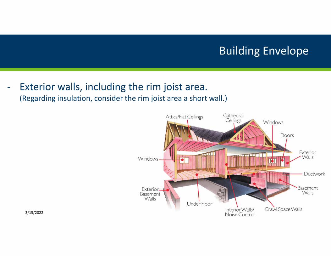
- Exterior walls including the rim joist area (Regarding insulation consider the rim joist area a short wall)
3152022
Basement Walls
AtticsFlat Ceilings
Interior Walls Noise Control
W indows
Exterior Walls
Ductwork
Basement Walls
Crawl Space Walls
Building Envelope
- Exterior walls including the rim joist area - Ceilingattic areas
3152022 37
insulation -----~
Insulation wind baffle 2 minimum space
water protectlon membrane --
ContiniUous sofllt vent
Vinyl or aluminu mi siding ___ ___
Rigid insulation (taped or sealed joints) ----1
Unfaced cavi y insu ation cellulose or lowbulldenslty spray-applied 1oarn
Continuous ridge ventilaUon -----
ventilation
__ Gypsum board with vapor semi-permeable 1atex paiint
consider increasing deptt o1 insulation by usi rtg deeper trusses or owrsized (longer) trusses
Caulking or sealant
Gypsum board with permeable latex paint
3152022
Vented attic assembly
38
Rooi insulation -----~
Insulation wind baffle 2 minimum space
water protectlon membrane --
ContiniUous sofllt vent
Vinyl or aluminu mi siding ___ ___
Rigid insulation (taped or sealed joints) ----1
Unfaced cavi y insu ation cellulose or lowbulldenslty spray-applied 1oarn
Continuous ridge ventilaUon -----
ventilation
__ Gypsum board with vapor semi-permeable 1atex paiint
consider increasing deptt o1 insulation by usi rtg deeper trusses or owrsized (longer) trusses
Caulking or sealant
Gypsum board with permeable latex paint
3152022 39
Vented attic assembly Unvented attic and unvented rafter assemblies - ldquoHot Roofrdquo
Building Envelope
- Exterior walls including the rim joist area - Ceilingattic areas - Floor area over an unconditioned space (Ex cantilever bonus room)
3152022 40
D middot n st is
Rooms 3152022 41
Your D middot n 1
St i 5 I
Rooms
Hase1Plate sealed to s u bfroor
~ pound _________
Insulation in pmiddotermanent contact withs~ bfloor
Blocking betwmiddoteen jo s -smiddotealled at p1e ri _ nteir
423152022
Building Envelope
- Exterior walls including the rim joist area - Ceilingattic areas - Floor area over an unconditioned space (Ex cantilever bonus room) - Basement floor or slab of a slab-on-grade system
3152022 43
Exterlorskllng ------olgtCI
Rigid lnsulatlon used as sheathing al lgns with foundation I nsulatlon-----Eft
Pressure tre-ited sill plate over termite shield anchlll seal
Flashing
Protection or coating
-----Interior finlm material
Insulation In 2 x 4 wall
4-ln concrete slab with optlonal wwme5h
~ middot~ =~~~~c = =i ----i( ) Rigid lnsulatlon may extend horizontally lntolhe soil 5loplng away from slab edge
Reinforcing
Concrete grade beam
Figure 4-9 Slab-on-Grade with Integral Grade Beam Exterior Insulation)
middot ~ I I II
i
7~ bull I
Different Types of Slab-on-Grade Floors
3152022 httpsfoundationhandbookornlgovhandbooksection4-1shtml
44
4033 Fro t-protected hallow foundation For building here the n10nthl mean temperature of the building is rnainshy
tained at not les than 64 degF (18degC footings are not required to extend belo the fro t line v here protected from fro t by insulation in accordance ith Figure R403 3(1 and Table R40 3(1 Foundation protected from fro t in accordance
ith Figure R40 _ 1 and Table R40 3 (1 hall not be u ed for unheated pace uch a porche utility room garage and carport and hall not be attached to basements or crm ll spaces that are not maintained at a 1ninimmn 1nonthl 111ea11 temperature of 64 degF 18deg
Material u ed belo grade for the purpo e of in ulating footing again t fro t hall be labeled a complying ith
TM _ 8
MRC R4033 amp Table R4033(1)
3152022 45
Foundoticln perimeter
C 3152022 46
Frost-Protected Shallow Foundation systems See Table R 4033(1) of the MRC and footnotes for minimum insulation location and thickness
3152022 47
TABLE R4033(1) MINIMUM FOOTING DEPTH AND INSULATION REQUIREMENTS FOR FROST-PROTECTED FOOTINGS IN HEATED BUILDINGS0
AIR FREEZING MINIMUM FOOTING VERTICAL HORIZONTAL INSULATION HORIZONTAL INSULATION DIMENSIONS
INDEX DEPTH D INSULATION R-VALUPe PER FIGURE R4033(1) (inches) (degF-days)b (inches) R-VALUEcd Along wa lls At corners A B C
1500 or le 12 45 Not required Not required Not required Not required Not required __ ooo 14 6 ot required ot required ot required ot required ot required
- middot 00 16 6 1 49 L _4 0
3000 16 8 6 86 1 _4 40
3-oo 16 90 80 112 24 30 60
4000 16 101 10- 131 _4 36 60
For SI 1 inch= _54 mm degC = [(degF) - 3-] l8 a Insulation requirements are for protection against frost damage in heated buildings n-1te1 middotahte ould be 1e~1u11 et middotto med ener_middot on-enmiddotition siandi1 tis
b See Figure R403 3(- ) or Table R4033(2) for Air Freezing Index values c Insulation materials shall provide the stated mininmm R-values under long-term exposure to moist below-grom1d conditions in freezing climates The
following R-values shall be used to detennine insulation thicknesses required for this application Type II expanded polystyrene (EPS)-3- R per inch for ve1ti al insulation and 6 R per in h for horizontal insulation Type IX expanded polystyrene (EPS -34 R per inch for ve11i al insulation and 8 R per inch for horizontal insulation Types IV VI VII and X extmded polystyrene (XPS)-4 R per inch for ve11ical insulation and 40 R per inch for horizontal insulation
d erti al insulation shall be expanded polystyrene insulation or extruded polystyrene insulation e Horizontal insulation sha ll be expanded polystyrene insulation or extruded polystyrene insulation
MRC R4033 amp Table R4033(1)
R40229 Slab-on-grade floors 1fu-01 -grade floor with a floQ middot middot urface le thai1 2 middot 1cbe middotmiddot J - ll11l be middot grade shall be insulated in accordance with Table R4021 1 The insulation shall extend downward from the top of the slab on the outside or inside of the foundation wall Insulation located below grade middothall e exteru e l h r tauce r -YicL middot able R-l02 l middot au middot con1binati 1 Yertical
ati n ext niling m er fhe - middot in u a-e middot e r - l ___ ~ _ ~ ll middot r 0 Insulation extending
away from the building hall be protected by pa ement or b a minimum of 1 O in he 254 mm) of oil The top edge of the in ulation installed between the exterfor 11middotall and the edge of the interior lab hall be pe1n1itted to be cut at a 4 -degree 0 9 rad angle av a from the exterior 1rall Slab-edge insulation i not required in jmi diction de igshynated b the code official a having a ve1y heavy te1mite inf e tation
MRE R40229 amp Table R40211
3152022 48
R40211 INSULATION AND FENESTRATION REQUIREMENTS BY COMPONENTa
CLIMATE FENESTRATION SKYLIGHTb GLAZED CEILINGi WOOD MASS FLOOR BASEMENrmiddot SLABd CRAWL ZONE U-FACTORb U-FACTOR FENESTRATION R-VALUE FRAME WALL R-VALUE WALL R-VALUE SPACEc i
SHGcbe WALL R-VALUEigh R-VALUE amp DEPTH WALL R-VALUE1 R-VALUE
6 03_ 055 NR 49 20 13+5 1520 3oe 15 10
15 35 ft
7 032 055 NR 49 21 1921 38e 15 10
15 5 ft
For SI 1 foot= 3048 mm a R-values are minimums -factors and SHGC are maximums When insulation is installed in a caYity that is less than the label or design thickne s of the
insulation the installed R-value of the insulation shall not be less than the R-value specified in the table b The fenestration -factor column excludes sl-ylights The SHGC column applie to all glazed fenestration c See Section R40228 d Insulation R-values for heated slabs shall be installed to the depth indicated or to the top of the footing whichever is less e Or insulation sufficient to fill the framing cavi R-19 minimum f First value is ca middotity insulation second is continuous insulation or insulated siding so 13+5 means R-13 cavity insulation plus R-5 continuous insulation or
insulated siding If structural sheathing covers 40 percent or less of the exterior continuous insulation R-value shall be permitted to be reduced b than R-3 in the locations where structural sheathing is used to maintain a consistent total sheathing thickness
g The second R-value applies when more than half the insulation is on the interior of the mass wall h When using log-type construction for thermal mass walls the following applies
l)a minimum ofa 7-inch diameter log hall be used and
2) the middot -value of fen tration products shall be 029 overall on average or better 1 See Section 40-28 A minimum R-19 ca ity insulation is required in wood foundation walls J- Roo ceiling assemblies shall have a minimum 6-inch energy heel 3152022 49
MRE R40229 amp Table R40211
TABLE R40211 INSULATION AN D FENESTRATION REQU IREMENTS BY COMPONENT
CLIMATE FENESTRATION SKYLIGHTb GLAZED CEILINGi WOOD MASS FLOOR BASEMEN-remiddot SLABd CRAWL ZONE U-FACTORb U-FACTOR FENESTRATION R-VALUE FRAME WALL R-VALUE WALL R-VALUE SPACE
SHGcbe WALL R-V ALU Eigh R-VALUE amp DEPTH WALL R-VALUEt R-VALUE
6 032 055 NR 49 20 13+5 1520 3oe 15 10
15 35 ft
7 032 055 NR 49 21 1921 3ge 15 10
15 5 ft
TABLE R4033(1) MINIMUM FOOTING DEPTH AND INSULATION REQUIREMENTS FOR FROST-PROTECTED FOOTINGS IN HEATED BUILDINGS3
AIR FREEZING MINIMUM FOOTING VERTICAL HORIZONTAL INSULATION HORIZONTAL INSULATION DIM ENSIONS
INDEX DEPTH D INSULATION R-VALUEc e PER FIGURE R4033(1) (inches) (degF-days)b (i nches) R-VALUEcd Along walls At corners A B C
1 -00 or le L 4 - ot required ot required ot required ot required ot required __ ooo 14 6 ot required ot required ot required ot required ot required
-middot -oo 16 6 1 49 L _4 40
3000 16 8 6 86 L _4 40
MRE vs MRC
3152022 50
51
Building Envelope
- Exterior walls including the rim joist area - Ceilingattic areas - Floor area over an unconditioned space (Ex cantilever bonus room) - Basement floor or slab of a slab-on-grade system - Foundation walls
3152022
Menardscom- - - - -52
Building Envelope
- Exterior walls including the rim joist area - Ceilingattic areas - Floor area over an unconditioned space (Ex cantilever bonus room) - Basement floor or slab of a slab-on-grade system - Foundation walls - Vapor Retarder
3152022 httpswwwowenscorningcomen usinsulationproductspng fiberglas kraft faced r13
53
Building Envelope
- Exterior walls including the rim joist area - Ceilingattic areas - Floor area over an unconditioned space (Ex cantilever bonus room) - Basement floor or slab of a slab-on-grade system - Foundation walls - Vapor Retarder - Air Barrier
3152022
- - - - - _
Vapor Retarder vs Air Barrier
bull A vapor barrier retarder does not provide a seal of the building components
3152022 54 httpswwwjlconlinecomhow toinsulationq a installing faced batts o
55
Vapor Retarder vs Air Barrier
bull An air barrier provides a seal of the building components
3152022
bull VAPOR RETARDER CLASS (located in Residential Building Code definitions) A measureof the ability of a material or assembly to limit the amount of moisturethat passes through that material or assembly Vapor retarder class shallbe defined using the desiccant method with Procedure A of ASTM E 96 asfollows
56
Vapor Retarder ndash RB Definitions
bull VAPOR RETARDER CLASS (located in Residential Building Code definitions) A measure of the ability of a material or assembly to limit the amount of moisture that passes through that material or assembly Vapor retarder class shall be defined using the desiccant method with Procedure A of ASTM E 96 as follows
3152022 MRC Section R202
bull VAPOR RETARDER CLASS (located in Residential Building Code definitions) A measureof the ability of a material or assembly to limit the amount of moisturethat passes through that material or assembly Vapor retarder class shallbe defined using the desiccant method with Procedure A of ASTM E 96 asfollows
bull Class I le 01 perm rating
bull Class II gt 01 to le 10 perm rating
bull Class III gt 10 to le 10 perm rating
57
Vapor Retarder ndash RB Definitions
bull VAPOR RETARDER CLASS (located in Residential Building Code definitions) A measure of the ability of a material or assembly to limit the amount of moisture that passes through that material or assembly Vapor retarder class shall be defined using the desiccant method with Procedure A of ASTM E 96 as follows
bull Class I le 01 perm rating
bull Class II gt 01 to le 10 perm rating
bull Class III gt 10 to le 10 perm rating
3152022 MRC Section R202
bull The vapor retarder class shall be based on the manufacturerrsquos certifiedtesting or a tested assembly
Vapor Retarder
bull The vapor retarder class shall be based on the manufacturerrsquos certified testing or a tested assembly
58 3152022 MRC Section R70272
bull The vapor retarder class shall be based on the manufacturerrsquos certifiedtesting or a tested assembly
bull The following shall be deemed to meet the class specified
Vapor Retarder
bull The vapor retarder class shall be based on the manufacturerrsquos certified testing or a tested assembly
bull The following shall be deemed to meet the class specified
3152022 MRC Section R70272 59
bull The vapor retarder class shall be based on the manufacturerrsquos certifiedtesting or a tested assembly
bull The following shall be deemed to meet the class specified
bull Class I Sheet polyethylene unperforated aluminum foil
60
Vapor Retarder
bull The vapor retarder class shall be based on the manufacturerrsquos certified testing or a tested assembly
bull The following shall be deemed to meet the class specified
bull Class I Sheet polyethylene unperforated aluminum foil
3152022 MRC Section R70272
bull The vapor retarder class shall be based on the manufacturerrsquos certifiedtesting or a tested assembly
bull The following shall be deemed to meet the class specified
bull Class I Sheet polyethylene unperforated aluminum foil
bull Class II Kraft-faced fiberglass batt (Does not mean it is an air barrier)
61
Vapor Retarder
bull The vapor retarder class shall be based on the manufacturerrsquos certified testing or a tested assembly
bull The following shall be deemed to meet the class specified
bull Class I Sheet polyethylene unperforated aluminum foil
bull Class II Kraft-faced fiberglass batt (Does not mean it is an air barrier)
httpswwwjmcomenblog2021maya-rare-approach-to-getting-grade-i 3152022 MRC Section R70272
bull The vapor retarder class shall be based on the manufacturerrsquos certifiedtesting or a tested assembly
bull The following shall be deemed to meet the class specified
bull Class I Sheet polyethylene unperforated aluminum foil
bull Class II Kraft-faced fiberglass batt (Does not mean it is an air barrier)
bull Class III Latex or enamel paint
Vapor Retarder
bull The vapor retarder class shall be based on the manufacturerrsquos certified testing or a tested assembly
bull The following shall be deemed to meet the class specified
bull Class I Sheet polyethylene unperforated aluminum foil
bull Class II Kraft-faced fiberglass batt (Does not mean it is an air barrier)
bull Class III Latex or enamel paint
3152022 MRC Section R70272 62
R7027 Vapor retarders A class I or II vapor retarder is required on the interior side of frame walls in Climate Zones 6 and 7 Class II vapor retarders are permitted only when specified on the construction documents
Vapor Retarder ndash MRC R7027
3152022 Optional Tagline Goes Here | wwwdlimngov 63
TABLE R70271 CLASS Ill VAPOR RETARDERS
CLIMATE CLASS 111 VAPOR RETARDERS PERMITTED FOR
ZONE
Vented cladding over wood structural panels
R7027l Class III vapor retarders Cla III apor ented cladding over fiberboard
retarder hall be permitted here of the condi-Marine ented cladding over gypsum any one 4
tions in Table R 702 7 1 is 111et Continuous in ulation with R-value 2 25 over 2 x 4 wall
Continuous insulation with R-value 2 3 75 over_ x 6 wall
Vented cladding over wood structural panels
Vented cladding over fiberboard
5 Vented cladding over gyp um
Continuous insulation with R-value 2 5 over 2 x 4 vall
Continuous insulation with R-value 2 75 over 2 x 6 wall
Vented cladding over fiberboard
6 ented cladding over gyp um
Continuous insulation with R-value 2 75 over 2 x 4 wall
Continuous insulation withR-value 2 1125 over 2 x 6 wall
Continuous insulation with R-value 2 l O over 2 x 4 wall 7 and 8
Continuou insulation with R-value 2 15 over 2 x 6 wall
For SI I polllld per cubic foot = 16 kgm a Spray foam with a maximum penneance of 15 pe1m s at the installed
thickness applied to the in terior cavity side of wood stmctural panels fibe rboard insulating sheathing or gypsmn is deemed to meet the continuous insulation requirement where th e spray foam R-value meets or exceeds the specified continuous insulation R-value
64
Paint as a Vapor Retarder ndash When
3152022
bull How to verify the coverage and application
bull If you do not use a Class I vapor retarder (for example 3 mil poly) what isthe air barrier
Paint as a Vapor Retarder - Challenges
bull How to verify the coverage and application
bull If you do not use a Class I vapor retarder (for example 3 mil poly) what is the air barrier
3152022 MRC Section R7027 65
ZONE
TABLE R70271 CLASS Ill VAPOR RETARDERS
CLASS Ill VAPOR RETARDERS PERMITTED FOR
1 ddin_ r 1un
iJ tlati n ith R- lu all
6 wall
b tual
m rn m R-v lu meet r
bull If the house is in Climate Zone 6 andcontinuous insulation is NOT usedhow does this affect our wallbracing
bull Challenges working with R-75+continuous insulation
bull Spray foam is an option (footnote a)
Paint as a Vapor Retarder - Challenges
bull If the house is in Climate Zone 6 and continuous insulation is NOT used how does this affect our wall bracing
bull Challenges working with R-75+ continuous insulation
bull Spray foam is an option (footnote a)
3152022 66
Minimum clear airspaces and vented openshyings for vented cladding For the purpo es of thi ection
ented cladding hall include the follo ing 1ninimum clear airspace Other openings with the equi alent ent area hall be permitted
1 inyl polypropylene or horizontal aluminum iding applied o er a eather-re i ti e batTier a pecified in Table R7033(1)
2 Brick eneer ith a clear air pace a pecified in Table R70384
3 Other appro ed ented cladding
bull What is required for vented cladding
Paint as a Vapor Retarder - Challenges
bull What is required for vented cladding
3152022 MRC Section R70273 67
bull AIR BARRIER Material(s) assembled and joined together to provide abarrier to air leakage through the building envelope
Air Barrier ndash RE Definitions
bull AIR BARRIER Material(s) assembled and joined together to provide a barrier to air leakage through the building envelope
3152022 68
TABLE R402411 AIR BARRIER ANO INSULATION INSTALLATION
COMPONENT CRITERIAbull
A continuous air barrier shall be installed in the building envelope
Air bamer and thermal bamer Exterior thermal envelope contains a continuous air barrier Breaks or joints in the air barrier shall be sealed Air-permeable insulation shall not be used as a sealing material
The air barrier in any dropped ceilingsoffit shall be aligned with the insulation and any gaps in the air bar-Ceilingattic rier sealed
Access openings drop down stair or knee wall doors to unconditioned attic spaces shall be sealed
Comers and headers shall be insulated and the junction of the foundation and sill plate shall be sealed The junction of the top plate and top of exterior walls shall be sealed
Walls Exterior thermal envelope insulation for framed walls shall be installed in substantial contact and continu-ous alignment with the air barrier Knee walls shall be sealed
Windows skylights and doors The space between windowdoor jambs and framing and skylights and framing shall be sealed
Rim joists Rim joists shall be insulated and include the air barrier
Floors Insulation shall be installed to maintain peml311ent contact with underside of subfloor decking (including above-garage and
cantilevered floors) The air barrier shall be installed at any exposed edge of insulation
Where provided in lieu of floor insulation insulation shall be permanently attached to the crawlspace walls Crawl space walls Exposed earth in unvented crawl spaces shall be covered with a Class I vapor retarder vith overlapping
joints taped
Shafts penetrabons Duct shafts utility penetrations and flue shafts opening to exterior or unconditioned space shall be sealed
I Narrow cavities Batts in narrow cavities shall be cut to fi t or narrow cavities shall be filled by insulation that on installation readily conforms to the available cavity space
Garage separation Air sealing shall be provided between the garage and conditioned spaces
Recessed lighting Recessed light fixttires installed in the building thermal envelope shall be air tight IC rated and sealed to the drywall
Plumbing and wiring Batt insulation shall be cut neatly to fit around wirmg and plumbing tn exterior walls or insulation that on installation readily conforms to available space shall extend behind piping and wiring
Showertub on exterior wall Exterior walls adjacent to showers and tubs shall be insulated and the air barrier installed separating then1 from the showers and tubs
Electricalphone box on exterior The air barrier shall be installed behind electrical or communication boxes or air sealed boxes shall be walls installed
HV AC register boots HV AC register boots that penetrate building thermal envelope shall be sealed to the subfloor or drywall
Fireplace An air barrier shall be installed on fireplace walls Fireplaces shall have gasketed doors
a In addition inspection oflog walls shall be in accordance with the proYisions of ICC-400 3152022 69
l ABLE R402411 AIR BARRIER AND IN SULATION INSlALLAllON
COMPONENT
Alr barrier arxl ihermal barrier
CeJlJno atilc
Walls
Wtndows sk yl ifhts and doors
RlmJolsls
Floors (tndudlng above-garage and cantilevered Doors)
Crawl space walls
Shafts penetraUans
Narrow cavtlles
Garage separation
Recessed llghUng
Plumbing and w1rtog
Showertub on exterior wall
Electrkalpho ne box on exterior walls
HV A regLster boots
Ftrep lace
CRITERIAbull
A comlnuous air barrier shall be Installed In the bulldtng envelape Exterior ttlermal envelope contains a conunuous air barrier Breaks or Jolllts In lhe air barrier shall be Alr-permeable tnsula1 lon s tiall oot be used as a sealJ10 malertaL
The alr barrler- In any dro JJIMd ceil111 soffH shall be aligned with the Jnsulal I on and any gaps In the air barrier I Access openings drop down stair or kree wall doors to uncondJIJoned attic spaces shall be luJi Corners and headers sha U be Insulated and the Junction oflhe foundation and sill plate shall be I TheJuncUoo of the lop plate and top of exterior wa ll s shall be I Extertor thermal envelope Insulation rar framed walls shall be lnsta lied In substanual con1act and rnnttnuous alignment ~vtth the air barrier Knee walls shatI be seal ed
The space between windowdoor Jambs and framing and sk lights and framing shall be 11wl1
Rim J olsts shall be 1nsul ated and lncl ude the alr barrier
lnsulaUon shall be Installed to maintain permanent contact wl1h undersldeofsubfloor decking The alr barrier shall be Install ed at any exposed edge of tnsulauon
Where provided In IJeu of floor lllsulaUon lnsulallon shall be pemianenHy attached to the crawlspace walls Exposed earth In unven ted crawl spaces shal l be covered wlh a Class I vapor retardff with overlapptngJatnts taped
Duct shafts uUllty penetrations and flue sliafts opening to exterior or uncondlt1oned space shall be
Batts tn mrmw cavities shall be cut m flt or narrow cavHtes shall be fi lled by Insulation thal on lnstallat lo n readll y conforms ta the available cavity space
Atr O shall be provided between the garage and condJt toned sparegt
Recessed light fixtures Installed In the bulldlno thermal envelope sliall be air U h IC rated and to the drywalL
Bau lnsulaUon shall be cul neatly lo flt amund wiring and plumbing In exlfflor wans or lnsulaUon tliat on lnstallallon readlly conforms 10 available space shaJI extend behind plplllg and Wir ing
ExterlorwalL~adJacent to showers and tubs shall be Insula ted and the air barrier Installed separating them from the showers and tubs
The air oomer shall be lnstaJted behind elocu tcal or communtcauon boxes or air boxes shall be tnslalled
HVAC register boots that peneuate buJldlng thermal envelope sliaU be middot lul to the subshy[loor or drywa ll
An air barrier shall be 111stalled on fireplace walls Fireplaces shall have gasketed doors
il fn addition mspedlon of Jog waUs shall be in accoruance with the provisions of ICC-40
Sealed
To close or make secure against access leakage or passage by a fastening or coating
Major Sources of Amiddotr Leaks Floor
Ifs a d
Doors
1
C llll
31
Air Barrier
bull An air barrier may be a single material or a combination of materials
3152022 72
I
R 2 ir leakage 11 1 p e bull lt Ja b 11 tr l te
dan e ith the r quir 111ent R o __
The buildin deg th 1IDal li111i lt ir 1 klt g in a r-
f e ti n R 4 _ 1 thr _ h
R-10241 Building thermal en e ope The buildino th 1110 nr lop hall ompl ith e ti n R O 41 and R O 1 he aling meth d et een di i111i ar rnateria hall llo f r differ ntial pan ion an n-
Section RE4024
3152022 73
Air Leakage ndash Why Regulate
bull Reduce energy consumption due to air leakage
3152022 74
1
Air Leakage ndash Why Regulate
bull Reduce energy consumption due to air leakage
bull Avoid moisture migration issues
3152022 75
LJ 1
Air Leakage ndash Why Regulate
bull Reduce energy consumption due to air leakage
bull Avoid moisture migration issues
bull Avoid uncomfortable drafts caused by cold air leaking in from the outdoors
3152022 76
77
MINNESOTA RESIOEHTlAl ENERGY CODE
R40l A Opbull qubull door nmprion Ono de-hmgd opaque door assembly up to 24 squarbull f ( 22 mj tRa lS eumptd from Ibo IJfador ~ Ul SCboa R402 I I Tlw eumpwa shall DOI apply IO Ibo U-factelt altmgtmmiddotbull app-11 u Sectoo R402 l3 mgtd Ibo to~ UA altmgtmmiddotbull in Seclioo R402 I 4
R40lS unroom 1-falttor All nmroonu ~ g coadlt1ooedspace shallmttt tbe ~~ of code
Exuprioa For SlDI_ wlh th-al uoloaon and ltOclosuig cood11ooed spacbull 111 Chmatbull ZoaH 4 through 8 Ibo foUowug -ptt Ibo rutnboll requiremoun of lhls code shall appl
Thbull mumwm fmutraboa U-factor shall be 04S and
2 The maxmmm bullhght Ufactor shall be 0 0 Nrw ~on sqmatmg 1hr nmroom w1tb tial uolanon from cOMlnoMd palaquo shall mltelt Ibo bidding th1 m-lopo ~ of middot code
R4036 R~bcemtal ftatttndon Wbat some- or all of m Wstugtg (ODHUabOO WI JS rqgtlacd Wllh I aw fenshyesttabOO product Ulcludulg md gbnog the rqgtlace meUI feoeuboll uml shall mttt he appbcable rqwrbullbull meUIS forUfactor andSHGC ID Table R402I I
I R40l4 Air Jb bull (Mandatory) The bwlduig lhmm1 flllope ll be C011$11UCtd 10 WWI ar lewgbull 111 accorshydmce with Ibo requu-emoats of Secboos R402 4 I through R40244
I R40l4l Bulldiac lhtrmal tanlop The 1gt111dng th4I mwo shall comply lh Secboos R4024 I I and R4024 l2 The sealng methods _ttll dJSsuwlar maienals diall allow (or ddfa-mnal apan11on and con-a-actJoo
R40l4l l lnnaUrion The compoamu of the lnuldshylng rhnfflal mmiddotiopo as Listed in Table R402 4 I I shall be UISlalled in accordmce wlh he tn11lllfacbftr bull UlStrucU md the cnttna hsled ID Table R4024 I I u apphcable IO the method of COIIStrucllOD WhtR ~ by the codbull offiruu an OPf1 ed tlw-d pany shall UISpeltt all CoapotgtellU aad -nfy ccmp-
R40l 4Jl T estinc The bwldiag or dlmiddotellDg U1111 shall be tes~ and _d as iaini 1W lbullalage nte of DOI ucttltlug S IU cbang per hour ID Chma~ loon I and and 3 chaog per ho- ID Chmallf loon 3 through 8 T HUDg shall be coaducled wtlh a blo= door 11 a pressutt of 02 1DCbe1 w g (SO Pascals) WhtR requu-d by he cod offiaa~ lftWlg shall be coodlgtcted by an OPf1 tlw-d patty A wnnen npon of me resul of lhbull - shall be gecl by th pany ~ th - and prosd to me cod offiaa T estuig shall be performed bullbull any time after crean011 of all pene1n111oos of me 11d1ng thlrlflal nrdo
0urutg IHhDg
Extltnor bullUldow and dooB fmplac Olld 0- doors shall be dosed bUl - ~lllbulld boOOd thbull
UlUllded weatbentnppmg or olhff 111filttaaoo COObOI
2 Dampers UlCluchng uha UllAle makeup IUr
bacLdml and ~ dampen shall be cloed bur DOC aled boyood mJltlded mfillnlboa COOIJOI lntenor doors u uscalld at the time of the tltgtl
shall be open
amptmcx doon for caatmuous middoteablaticm systems and heat recoiwy -nnlators shall be closed and
111d
S HHtuig lllld coolmg sys u ~led al th
t1me ofme shall be hD1gtNI of and
6 Supply and fflWD regucn u U1Slalled t the time ofme t shall be fi1II
R40l4 Firtplalaquos New bullOCgtCl--bunlUlg fiRplacff shall bamiddotbull 11gh1-6ruog Que dampen lllld ourdoor combosboa I 1W
R40l43 ftntlttnrion air Iuka t -- yhglm md gthdiag glabull doors sball ba~ 11D ar mfillnlbOO ratbull of no more lhan Ol cfm per tqCW~ foot (D sm) md SUlglllg doors 110 mou than 0 S cfm per squan fool (26
sm) 11n tH$NI according co NFRC 400 or ~ IA
WDMACSA 1011S A440 by an accrechted Uldtpenshydeot laboratory aad Imlaquo and loMled by the tn11lllfac IURlt
Ein pdoa Stt-bwl1 Uldo1- styhgbU and doors
R40l 4A Rtlt d ti1htinc Recnsed luawwres ll1SWled ID the bwdJng tMnna ervdopo shall be aled
luwt lealage -- and --middot uooed spaces AU recessed luowwRs shall be IC-rs~ I md lobded as ia-utg ao au- leabge ra~ DOI~ than 0 cfm (0 944 s 1en t ed 111 acconi- lh ASThl E 283 atbull I S psf (7S Pa) pressune cldmmtal All recessd lumuwr sball be sealed lh bull gaskOt or caulk boramiddot he housing and the 1111=laquo wall or cewng CO~
Ra 2~ llirlmum ftaHtndon e-ru1or and SBC datory) The area-waghld affll awumum fenes1111boa U-faccor pmwned using tndeoffs ampom Secton R402 I 4 or R40S shall be 0 48 ID Chma~ Zones 4 and Sand 0 40 ID Chshyma~ ZooH 6 through 8 for fl1cal ffflHlnlnca and O 7S u
Chma~ ZooH 4 lhrltRlgh 8 for yhgltts Tb area-wagbted ge awwnwn feneunoa SHGC perm111d ming
tndeofs ampom Secboc R40S m Chmatbull Zaes I through l shall be 0 SO
ECTION R403 Y TEM
R4 31 ontrob hndatory) At lbulluc oa thamosw sball be fOlded for bullbullch separatbull be tutg aod coohng s em
R403JJ Procnmmabk tbtrmostat Vberbull the pnmary hratmg n a forcedaJr fumace t lnst one tbttmo I tal per clwbulllhng UDll shall be Capable of comrolhng me heahllg and coohng sys1m oo bull daily scbdule to mamshytam chfferm1 temperatw~ pom at dtfferm1 tuDH of
3152022
Section RE402412 Air Leakage (Mandatory)
78
201$ MINNESOTA RESIOEHTlAl ENERGY CODE
R40l A Opbull qubull door nmprion Ono de-hmgd opaque door assembly up to 24 squarbull f ( 22 mj tRa lS eumptd from Ibo IJfador ~ Ul SCboa R402 I I Tlw eumpwa shall DOI apply IO Ibo U-factelt altmgtmmiddotbull app-11 u Sectoo R402 l3 mgtd Ibo to~ UA altmgtmmiddotbull in Seclioo R402 I 4
R40lS unroom 1-falttor All nmroonu ~ g coadlt1ooedspace shallmttt Ibo~~ of code
Exuprioa For SlDI_ wlh th-al uoloaon and ltOclosuig cood11ooed spacbull 111 Chmatbull ZoaH 4 through 8 Ibo foUowug -ptt Ibo rutnboll requiremoun of lhlS code shall appl
I Thbull mumwm fmutraboa U-factor shall be 04S and
2 The maxmmm bullhght Ufactor shall be O 0 Nrw ~on sqmatmg 1hr nmroom w1tb tial uolanon from cOMlnoMd palaquo shall mltelt Ibo bidding th1 m-lopo ~ of middot code
R4036 R~bcemtal ftatttndon Wbat some- or all of m Wstugtg fODHUabOO WI JS rqgtlacd Wllh I aw fenshy
esblbOO product Ulcludulg md gbnog the rqgtlace meUI feoeuboll uml shall mttt he appbcable rqwrbullbull meUIS forUfactor andSHGC 111 Table R402I I
I R40l4 Air Jb bull (Mandatory) The bwlduig bullbulllope u be c011$11UCtd 10 1uw iewgbull 111 dmce with Ibo requu-emoats of Secboos R402 4 I R40244
R40l4l Bulldiac lhtrmal tanlopbull 1gt111dng th4I mwo shall comply lh oos R4024 I I and R4024 l2 The sealng melh s _a dJSsuwlar mataUs shall allow for chf1i bal apausoo mid coo-UllctJOO
UlUllded wutbentnppmg or otha- uililmbOO COObOI meuuregt
2 Dampers UlCludug uha UllAle makeup IUr
bacLdml aod ~ dampen shall be cloed bur DOC 111d boyood mJltlded mfiltmboa COOIJOI lntenor docn if=~ bullbull Ibo nme of Ibo _ shall be open
4 amptenor doon for caatmuous middoteablatKm ems mid heat -co-ry -entlWorS shall be C ~ and
111d
if UlSlalled t Ibo li11ly open
R40l4 l Firtpbts N bull-oocl--bunuig fiRpbcff shall bamiddotbull 11ght-6nmg a ampa and ourdoor combmoa I R40l43 Ft tnrioa air Iuka t -- yltglm aod sit glabull docn shall bae mgt ar lllliltmbOO ratbull of no m than 03 cfm p- square foot (D sm) aod Sl doon no mou than O S cfm p- squase foOI (26
s_ m) 11a tH$NI ac~ to NFRC 400 or ~ IA
WD~IACSA 1011S A440 by an accrech1S IDdtpenshydltot bbontory and Imlaquo and lobolMI by Ibo manufx URlt
Ein pdoa Stt-bwlt ~ styltgbU mid docn
R40 l 4A Rttnwd ti1htinc ~ luawwres U1SWld 10 Ibo bwdJng tMnnal ervolopo shall be 111d
luwt au leakap _a cooclttiand and uoconda uooed spaces All recessed luowwrH shall be IC-ra aod loblod as baUtg an air leabg rate DOI more bull 0 cfm (0 944 s) 1-bett t d 111 acccrdonce ASThl E 283 at a I S psf (7S Pa) p-essune
R40l4 l l Jn raU bull n The compoamu of Ibo lnuld- 1umuwr shall be sealed lgtlh or caulk 1gtoramiddotttn lngrhOfflal u ltstedia Table R402 4 I I shall he bousutg and Ibo ut1en bullallor~wngltO-nng be utStalld accordmce wlh he manufxnnr bull
and Ibo cnttna ltsld ID Table R4024 1 I R4 lLni mum srnrioa C-fu10r aud SBC ble to Ibo method of construc1JOD Whne datory) The a-wagllld n-rage awumum r 1111uon
by Ibo codbull offictal appnn od tlw-d pany U-facmiddot19gt-pampwroed usug tndeoffs ampom Sectoo R402 I 4 or UlSpeltt all ltompoamts aod -nfy compltance wJI be O 48 ID Climate loaes 4 aod SW O JO 10
============-----ma ZooH 6 through S for fllcal ffflHllll R40~4l THrinJ ThebwldiagordwellUlgU1111shall Chmare zoo 4 lhrltRlgh 8 for y be restd aod -nliecl n bang air lbullakagt of nbullragbull awamnm feoeu GC pmrund ming
DOI =~ S 1W cbang per hour 111 Climate Zones tndeofs ampom Stet S m Climate Zaes I through 3 I aod 2 aod 3 aucbaa p-bour ID Cltma Zoaes 3 shall be O through 8 TH1l1l shall be coaductd wtth a bl01lshydoor at a ~ of O tDltbes w - (SO Pascals Wltfte requtred by the COM officral -a cooducted by apprr1od third nnm report of he r cf he upted by Ibo patty coadoctutg the prodd to he COM offiaal T est1Df ptrformtd a y time after auboo of
tnbom of the bwldm ti m lo
Duruig testing
I Extltnor nc1ow and dooB firqgtbc mid deg- docn shall be closd bUl - salocl boOOd thbull
ECTION R403 Y TEM
rosnmmabk lhermosta1 Where Ibo pnmary hratmg n a forcedaJr fumace t lnst one tbttmo stal p- clwbulllliag mw shall be capable of comrolliag he hntmg and cooling sysrem oo bull datly scltdule to momshytam chfferm1 temperatw~ pom at dtfferm1 tuDH of
-
R402412 Testing The buildin or d lli11o unit shaU b t st d and erified as ha ing an air leakage rate of not exce ding 5 air changes per hour in Climate Zones 1 and 2 and 3 air chang s p r hour in Climat Zon s 3 through Testing shall be conducted ith a blower door at a pressure of 02 inches wg 50 Pascals) Where required by the code official testing shall be conducted by an approved third party A written report of the results of the test shall b signed by the party conducting the test and pro ided to the code official Testin shall be perform d at an time aft r creation of all pen trations ofth building th nnal n lop
3152022
Section RE402412 Air Leakage (Mandatory)
Air Leakage Test
bull Max 3 ACH in zones 6 amp 7
bull Max 26 ACH if using R10 foundation insulation exception
3152022 79
Energy Systems
Building Envelope
R402 Mechanical Systems
R403 amp R4035
3152022 80
~ ~-~ -~ ~----~-~
Mechanical Systems
bull Heat loss
bull Equipment sizing
bull Mechanical ventilation
81
Sizing the Mechanical Equipment
3152022 82
Heat Loss
R403517 Climatic design Conditionsbull ASHRAE Handbook of Fundamentals
bull ACCA Manual J (Air Conditioning Contractors of America)
How is Heat Loss Calculated
R403517 Climatic design Conditions bull ASHRAE Handbook of Fundamentals
bull ACCA Manual J (Air Conditioning Contractors of America)
3152022 83
Q=UA(dT) is the general formula for heat loss
Formula for Heat Loss
Q=UA(dT) is the general formula for heat loss
3152022 84
Q=UA(dT) is the general formula for heat lossbull Q = Heat loss (what we are trying to define)
bull Specifically the BtursquosHour of heat loss
bull Btu = British Thermal Units
bull 1 Btu = amount of heat required to raise the temperature of one pound of water by one degreeFahrenheit
Q=UA(dT)
Q=UA(dT) is the general formula for heat loss bull Q = Heat loss (what we are trying to define)
bull Specifically the BtursquosHour of heat loss
bull Btu = British Thermal Units
bull 1 Btu = amount of heat required to raise the temperature of one pound of water by one degree Fahrenheit
3152022 85
-
What exactly is this equation Why do we need tounderstand it
bull Q = Heat loss (what we are trying to define)
bull U = U-factor of the assembly
bull U-value (U-factor) a measure of the heat transmission through a building part (such as a wall orwindow) or a given thickness of a material (such as insulation) with lower numbers indicating better insulating properties - Merriam Webster
bull R-value a measure of resistance to the flow of heat through a given thickness of a material (suchas insulation) with higher numbers indicating better insulating properties - Merriam Webster
Q=UA(dT)
What exactly is this equation Why do we need to understand it
bull Q = Heat loss (what we are trying to define)
bull U = U-factor of the assembly
bull U-value (U-factor) a measure of the heat transmission through a building part (such as a wall or window) or a given thickness of a material (such as insulation) with lower numbers indicating better insulating properties - Merriam Webster
bull R-value a measure of resistance to the flow of heat through a given thickness of a material (such as insulation) with higher numbers indicating better insulating properties - Merriam Webster
3152022 86
What exactly is this equation And why do we need tounderstand it
bull Q = Heat loss (what we are trying to define)
bull U = U-factor of the assembly
bull A = the Area of the assembly
bull Length (width) of wall x height
Q=UA(dT)
What exactly is this equation And why do we need to understand it
bull Q = Heat loss (what we are trying to define)
bull U = U-factor of the assembly
bull A = the Area of the assembly
bull Length (width) of wall x height
3152022 87
What exactly is this equation And why do we need tounderstand it
bull Q = Heat loss (what we are trying to define)
bull U = the U-factor of the assembly
bull A = the Area of the assembly
bull (dT) = Delta T (ΔT) or temperature difference
bull Minimum outdoor design temperature plus the interior design temperature = ΔTbull 70 degree indoor amp -20 degree outdoor = 90 degree ΔT
bull Said differently there is a 90 degree temperature swing from -20 to 70
Q=UA(dT)
What exactly is this equation And why do we need to understand it
bull Q = Heat loss (what we are trying to define)
bull U = the U-factor of the assembly
bull A = the Area of the assembly
bull (dT) = Delta T (ΔT) or temperature difference
bull Minimum outdoor design temperature plus the interior design temperature = ΔT
bull 70 degree indoor amp -20 degree outdoor = 90 degree ΔT
bull Said differently there is a 90 degree temperature swing from -20 to 70
3152022 88
Simple heat loss calculationbull Heat loss calculation for one wall
bull Then adding a window to same wall
bull Note the changes in heat loss due to the window
Example
Simple heat loss calculation bull Heat loss calculation for one wall
bull Then adding a window to same wall
bull Note the changes in heat loss due to the window
3152022 89
--- = U Factor - = 005
Q = UA(dT) = heat load assessment = defines equipmentsizing
bull Example Room is 10rsquo x 10rsquo x 10rsquo
bull Using 2x6 wall fiberglass insulation R-value ~R20
bull Convert R-value (R20) to U-factor by dividing 1 by the R-value
bull The U-factor is 005
Example
Q = UA(dT) = heat load assessment = defines equipment sizing 10rsquo
10rsquo
bull Example Room is 10rsquo x 10rsquo x 10rsquo
bull Using 2x6 wall fiberglass insulation R-value ~R20
bull Convert R-value (R20) to U-factor by dividing 1 by the R-value
bull
The U-factor is 005
3152022 90
1--1
One wall only
Example ndash 1 Wall
One wall only
3152022 91
1--1
bull One wall that is 10rsquo tall and 10rsquo wide equals an Area (A) of 100 Sq Ft
Example ndash 1 Wall
bull One wall that is 10rsquo tall and 10rsquo wide equals an Area (A) of 100 Sq Ft
3152022 92
V _ _____J -y---J --
r
bull One wall that is 10rsquo tall and 10rsquo wide equals an Area (A) of 100 Sq Ft
bull Btursquos per hour (Q) = 005 (U) x 100 Sq Ft (A) x 90 (dT)
Example ndash 1 Wall
bull One wall that is 10rsquo tall and 10rsquo wide equals an Area (A) of 100 Sq Ft
(U-factor of (Temperature (Heat loss) assembly) (Area) delta)
bull Btursquos per hour (Q) = 005 (U) x 100 Sq Ft (A) x 90 (dT)
Q=UA(dT)
3152022 93
Q = 005 X 100 X 90
Q = 450
1--1
bull 1 Wall that is 10rsquo tall and 10rsquo wide Equals an Area (A) of 100 Sq Ft
bull Btursquos per hour (Q) = 005 (U) x 100 Sq Ft (A) x 90 (dT)
bull Btursquos per wall for design loads = 450 Btursquos heat loss
bull
bull
Example ndash 1 Wall
bull 1 Wall that is 10rsquo tall and 10rsquo wide Equals an Area (A) of 100 Sq Ft
bull Btursquos per hour (Q) = 005 (U) x 100 Sq Ft (A) x 90 (dT)
bull Btursquos per wall for design loads = 450 Btursquos heat loss
bull
bull
3152022 94
bull 4 walls at 450 Btursquos each (4 x 450) = 1800 Btursquos of heat loss everyhour through the walls
bull Requires a heating appliance capable of supplying a minimum of1800 Btursquos per hour
bull Should we oversize
bull Up to 40 (Section 403517 A)
bull More is not good
Example ndash 4 Walls
bull 4 walls at 450 Btursquos each (4 x 450) = 1800 Btursquos of heat loss every hour through the walls
bull Requires a heating appliance capable of supplying a minimum of 1800 Btursquos per hour
bull Should we oversize
bull Up to 40 (Section 403517 A)
bull More is not good
3152022 95
bull Wall 4 was 100 Sq Ft at 005 U-Factor
bull Now the wall is only 84 Sq Ft (100 ndash 16 Sq Ft window) at the 05 U-Factor plus add a 16 Sq Ft window at a 032 U-Factor
Example ndash 4 Walls + 1 Window
bull Wall 4 was 100 Sq Ft at 005 U-Factor
bull Now the wall is only 84 Sq Ft (100 ndash 16 Sq Ft window) at the 05 U-Factor plus add a 16 Sq Ft window at a 032 U-Factor
3152022 96
bull Wall 1 = 05 x 100 x 90 = 450 Btursquos
bull Wall 2 = 05 x 100 x 90 = 450 Btursquos Windows can make a big overall difference
bull Wall 3 = 05 x 100 x 90 = 450 Btursquos
bull Wall 4 = 05 x 84 x 90 = 378 Btursquos
bull Walls = 1728 Btursquos
bull Add window in wall 4 =
32 119909 16 119878119902 119865119905 119909 90 461 119861119905119906 119904
bull Total Btursquos heat loss = 2189 Without the window the total
Btursquos were 1800 The window adds 389 Btursquos of heat loss
=
Example ndash 4 Walls + 1 Window
bull Wall 1 = 05 x 100 x 90 = 450 Btursquos
bull Wall 2 = 05 x 100 x 90 = 450 Btursquos Windows can make a big overall difference
bull Wall 3 = 05 x 100 x 90 = 450 Btursquos
bull Wall 4 = 05 x 84 x 90 = 378 Btursquos
bull Walls = 1728 Btursquos
bull Add window in wall 4 =
32 119909 16 119878119902 119865119905 119909 90 = 461 119861119905119906 119904
bull Total Btursquos heat loss = 2189 Without the window the total
Btursquos were 1800 The window adds 389 Btursquos of heat loss
3152022 97
Example - Floor
bull Basement floor with areas of 66rsquo x 30rsquo and 14rsquo x 8rsquo
bull Remember the equation Q = UA(dT)
bull The following are the given
bull R value of 2 for the basement floor
bull Under slab ground temperature of 55 degrees
bull Interior design temperature of 70 degrees
bull What is the total heat loss of the floor only
3152022 98
Example - Floor
bull Q = UA (dT) bull Figure out (U) and (dT)
bull R2 basement floor convert to U-factor
bull
=
bull 119880 119865119886119888119905119900119903 = 05
bull Under slab ground temperature of 55 degrees interior design temperature of 70degrees
bull Difference is 70 minus 55
bull ∆119879 = 15
3152022 99
Example - Floor
bull Floor area 1
bull 66 119909 30 = 1980 119878119902119865119905
bull Floor Area 2
bull 14 119909 8 = 112 119878119902119865119905
bull Total floor area 1980 119878119902119865119905 + 112 119878119902119865119905 = 120784 120782120791120784 119930119954119917119957
bull Floor area heat loss Q = (U) 05 x (A) 2092 x (dT) 15 = 15690 Btursquos
3152022 100
How is sizing determined
3152022 101
Equipment Sizing
102
RE4036 - Equipment Sizing ACCA Manual lsquoJrsquo Manual lsquoSrsquo
bull RE403517 A
bull (Residential heating and cooling) HVAC equipment shall be sized according to ACCA Manual S or an equivalent method based on the buildingrsquos heating and cooling load calculations by using ASHRAE Handbook of Fundamentals or the ACCA Manual J hellip
bull ACCA = Air Conditioning Contractors of America
3152022
RE4036 - Equipment Sizing ACCA Manual lsquoJrsquo Manual lsquoSrsquo
bull Manual J establishes the heating and cooling load calculations and guides HVAC designers to use ACCA Manual S to select equipment that is the right size
bull Manual S sets equipment sizing limits as summarized in Table 1
3152022 103
ACCA Manual S = Sizing of Equipment
3152022 104
bull Why is proper sizing so important
3152022 Optional Tagline Goes Here | wwwdlimngov 105
Mechanical ventilation requirements in the Energy code
3152022 106
Ventilation
1322202 Definition of Mechanical Ventilation
bull RE202 Definitions MECHANICAL VENTILATION The mechanical process of supplying conditioned or unconditioned air to or removing it from any space
3152022 107
108
Why Ventilate
bull Homes are built tighter now Need to address
bull Air quality concerns stagnant air viruses mold odors synthetic materials off-gassing etc
bull Moisture management
3152022
40121 Ventilation in IRC builcling entilation in building on tru ted in a cordau e ith the IRC hall compl ith inne ota Rule Chapter 1 22
40122 entilation in Group R-2 R-3 ancl R-4 occushypancies three middot torie and le in height entilation in Group R- R- and R-4 occupan ie three torie and le in height hall b pro ided ith a balan d entilation
tern and hall compl ith the fan efficac require-n1ent located in inne ota Rule Chapter 1 2 and the
entilation requirement in 1 inne ota Rules Chapter 1 22 or 2 HRAE 622 ~ 11tiotio11 and Ace ptobl Indoor Ar QuaUy n Resdenhal B1dfdngs
109 109
MN Mechanical Code
3152022 Optional Tagline Goes Here | mngovwebsiteurl
Balanced Ventilation
bull R4035 Mechanical ventilation (mandatory)
The building shall be provided with a balanced mechanical ventilation system that is +-10 percent of the systemrsquos design capacity and meets the requirements of Section R40355 which establishes the continuous and total mechanical ventilation requirements for dwelling unit ventilation hellip
3152022 110
Why Balanced
bull Provide acceptable indoor air quality
3152022 111
Why Balanced
bull Provide acceptable indoor air quality
bull Balancing the ventilation keeps more of a neutral pressure on the building envelope saving energy
3152022 112
Why Balanced
bull Provide acceptable indoor air quality
bull Balancing the ventilation keeps more of a neutral pressure on the building envelope saving energy
bull Evens out temperatures in the house for hot and cold spots
3152022 113
Quantity and Type of Ventilation
bull Total Ventilation Rate
bull Shall provide sufficient outdoor air = total ventilation rate average for each one-hour period in accordance with Table R40352
bull Continuous Ventilation
bull A minimum of 50 of the total ventilation rate but not less than 40 CFM on a continuous rate average for each one-hour period in accordance with Table R40352 or Equation 40352
3152022 114
1
Conditioned space 1 (in sq ft) Total
Continuous
1000-1500 6040
1501 -2000 7040
2001-2500 8040
2501 -3000 9045
3001-3500 10050
3501-4000 11055
4001 -4500 12060
4501--000 1306-
5001 -5500 14070
5501-60002 15075
TABLE R40352 NUMBER OF BEDROOMS
2 3
Total Total Continuous Continuous
7540 9045
8543 10050
9548 11055
105r 3 12060
11558 13065
12563 14070
13568 15075
14573 16080
15578 17085
16583 18090
1 Conditioned space includes the basement and conditioned crawl spaces 2 If conditioned space exceeds 6000 sq ft or there are more than 6 bedrooms use Equation R4035 2
4 5
Total Total Continuous Continuous
10553 12060
11558 13065
12563 14070
13568 1-0175
14573 16080
15578 17085
16583 18090
17588 19095
18593 200100
19598 2101 05
52
Total Continuous
13568
14573
15578
16583
17588
18593
19598
2051 03
215108
2251 13
M N M N M N M N M N M N M N M N M N M N M N M N M N M N M N M N M N M M N M ll
Table R40352 Total Ventilation Rate
3152022 115
1
Conditioned space 1 (in sq ft) Total
Continuous
1000-1500 6040
1501 -2000 7040
2001-2500 8040
2501 -3000 9045
3001-3500 10050
3501-4000 11055
4001 -4500 12060
I 4501--000 I 1306-
5001 -5500 14070
5501-60002 15075
TABLE R40352 NUMBER OF BEDROOMS
2 3
Total Total Continuous Continuous
7540 9045
8543 10050
9548 11055
105r 3 12060
11558 13065
12563 14070
13568 15075
14573 16080
15578 17085
16583 18090
1 Conditioned space includes the basement and conditioned crawl spaces 2 If conditioned space exceeds 6000 sq ft or there are more than 6 bedrooms use Equation R4035 2
4 5
Total Total Continuous Continuous
10553 12060
11558 13065
12563 14070
13568 1-0175
14573 16080
15578 17085
16583 18090
17588 19095
18593 200100
19598 2101 05
52
Total Continuous
13568
14573
15578
16583
17588
18593
19598
2051 03
215108
2251 13
M N M N M N M N M N M N M N M N M N M N M N M N M N M N M N M N M N M M N M ll
Table R40352 Total Ventilation Rate
3152022 116
1
Conditioned space 1 (in sq ft) Total
Continuous
1000-1 500 6040
1501-2000 7040
2001-2500 8040
2501-3000 9045
3001-3500 10050
3501-4000 11055
4001-4500 12060
I 4501--000 I 1306-
5001-5500 14070
5501-60002 15075
TABLE R40352 NUMBER OF BEDROOMS
2 3
Total Total Continuous Continuous
7540 9045
8543 10050
9548 11055
105r 3 12060
11558 13065
12563 14070
13568 15075
14573 16080
15578 17085
16583 18090
1 Conditioned space includes the basement and conditioned crawl spaces
I
2 If conditioned space exceeds 6000 sq ft or there are more than 6 bedrooms use Equation R403 52
4 I 5
Total Total Continuous Continuous
10553 12060
11558 13065
12563 14070
13568 1-0175
14573 16080
15578 17085
16583 18090
17588 19095
18593 200100
19598 2101 05
52
Total Continuous
13568
14573
15578
16583
17588
18593
19598
2051 03
215108
2251 13
M N M N M N M N M N M N M N M N M N M N M N M N M N M N M N M N M N M M N M ll
Table R40352 Total Ventilation Rate
3152022 117
1
Conditioned space 1 (in sq ft) Total
Continuous
1000-1 500 6040
1501-2000 7040
2001-2500 8040
2501-3000 9045
3001-3500 10050
3501-4000 11055
4001-4500 12060
I 4501--000 I 1306-
5001-5500 14070
5501-60002 15075
TABLE R40352 NUMBER OF BEDROOMS
2 3
Total Total Continuous Continuous
7540 9045
8543 10050
9548 11055
105r 3 12060
11558 13065
12563 14070
13568 15075
14573 16080
15578 17085
16583 18090
1 Conditioned space includes the basement and conditioned crawl spaces
I
2 If conditioned space exceeds 6000 sq ft or there are more than 6 bedrooms use Equation R403 52
4 I 5
Total Total Continuous Continuous
10553 12060
11558 13065
12563 14070
13568 1-0175
14573 16080
15578 17085
16583 18090
17588 I 19095
18593 200100
19598 2101 05
52
Total Continuous
13568
14573
15578
16583
17588
18593
19598
2051 03
215108
2251 13
M N M N M N M N M N M N M N M N M N M N M N M N M N M N M N M N M N M M N M ll
Table R40352 Total Ventilation Rate
3152022 118
WHOLE HOUSE FA WITHIN 4 - O OF
INTAKE REQUlRES ZONE RATING LE56
THAN 15
Mechanical Ventilation
Exhaust Only Systems (no longer Allowed)
3152022 119
TAKEOFF COLLAR
DAMPER
AIR RETURN SIDE OF HEATING SYSTEM
24 HOUR TIMER WITH ONOFF SWITCH WIRED PARALLEL TO FURNACE FAN
FURNACE
MANUAL DAMPER REQUIRED MOTORIZED DAMPER RECOMMENDED IN SOME LOCATIONS
WHOLE HOUSE FAN WITHIN 4 - D OF
INTAKE REQUIRES ZONE RA TING LESS
THAN 15
Ventilation must be Balanced
Supply Exhaust
Supply Only System Exhaust-Only System
TAKEOFF COLLAR
DAMPER
AIR RETURN SIDE OF HEATING SYSTEM
24 HOUR TIMER WITH ONOFF SWITCH WIRED PARALLEL TO FURNACE FAN
FURNACE
MANUAL DAMPER REQUIRED MOTORIZED DAMPER RECOMMENDED IN SOME LOCATIONS
WHOLE HOUSE FAN WITHIN 4 - D OF
INTAKE REQUIRES ZONE RA TING LESS
THAN 15
Ventilation must be Balanced
Supply Exhaust
Supply Only System - interlocked with an - Exhaust-only System
HEAT RECOVERY VENTILATION SYSTEM
COPYRIGHT O 2012 REST OVATE LID- ALL RIGI-ITS RESERIEO
Supply - interlocked with - Exhaust
Energy Systems
Building Envelope
R402 Mechanical Systems
R403 amp R4035
Service Water Heating
R4033 amp R4034
3152022 123
Service Water Heating
bull Pipe insulation on hot water lines
3152022 124
R40342 Hot Water Pipe Insulation
bull Hot water piping will be insulated to at least R-3 as follows 1 Piping larger than 34rdquo diameter
2 Piping serving more than one dwelling unit
3 Piping from water heater to kitchen outlets
4 Piping located outside the conditioned space
5 Piping from the water heater to a distribution manifold
6 Piping located under a floor slab
7 Buried piping
8 Supply and return piping in recirculation systems other than demand recirculation systems
9 Piping with run lengths greater than the max run lengths for the nominal pipe diameter given inTable R40342
TAB LE R403 4 2 MAXIMUM RUN LENGTH (feet)a
Nominal Pipe Diameter of Largest 3 l 2 Dia1neter Pipe in the Run (inch) 8
Maximum Run Length 30 20
For SI 1 inch = 254 1mn 1 foot = 3048 nun
3 4
gt 3 4
10 5
a Total length of all piping fro1n the distribution 111anifold or the recirculation loop to a point of use
R40342 ndash Hot water pipe insulation
All remaining piping shall be insulated to at least R-3 or meet the run length requirements of Table R40342
Energy Systems
Building Envelope
R402 Mechanical Systems
R403 amp R4035
Service Water Heating
R4033 amp R4034
Electrical Systems
R404
3152022 127
Prescriptive Lighting Equipment
3152022 128
Prescriptive Lighting Equipment
RE Section R404
A minimum of 75 of the lamps in permanently installed lighting fixtures shall be high-efficacy lamps or a minimum of 75 of permanently installed lighting fixtures shall contain only high efficacy lamps
3152022 129
Prescriptive Lighting Equipment RE Section R404
A minimum of 75 of the lamps in permanently installed lighting fixtures shall be high-efficacy lamps or a minimum of 75 of permanently installed lighting fixtures shall contain only high efficacy lamps
Exception
Low-voltage lighting
3152022 130
402 44 Recessed lighting Rece ed lmninaire in talled in the building thermal e11velope hall be ealed to limit air leakage be een conditioned and uncondishytioned pace All rece ed luminaire hall be I -rated and labeled as having an air leakage rate not more than 20 cfin 0944 L hen te ted in accordan e ith A T E 283 at a 1 p f Pa pre ure differential All rece ed lnnlinaires hall be ealed ith a ga ket or caulk between the hou ing and the interior all or ceiling covering
Recessed Lighting Fixtures RE Section R40244
Type IC rated and labeled as meeting ASTM E 283 when tested at 157 psf (75 Pa) pressure differential with no more than 20 cfm of air movement
3152022 131
40244 Recessed lighting Rece ed luminaires in talled in the building thermal enr lope hall be ealed to limit air leaka 0 e betv een conditioned and uncondishytioned pace All rece ed luminaire hall be IC-rated and labeled as ha ing an air leakage rate not more than __ o cfin 0944 L hen te ted in accordance ith T E
83 at a 1 p f Pa pre ure differential All rece ed luminaires shall be ealed ith a ga ket or caulk between the hou ing and the interior v all or ceiling co enndeg
Recessed Lighting Fixtures RE Section R40244
Type IC rated and labeled as meeting ASTM E 283 when tested at 157 psf (75 Pa) pressure differential with no more than 20 cfm of air movement
Sealed with a gasket or caulk between the housing and interior wall or ceiling covering
3152022 132
What is Required for Plan Review
Submittal Documents
Submittal Documents
bull What is required for a proper plan review of the building and the buildings ldquoEnergyrdquo systems
3152022 134
13220103 CONSTRUCTION DOCUMENTS
M N M N M
Constrnction documents shall be ch-a n to scale upon suitable N M
material Electronic media documents are pennitted to be N M
submitted when approved by the building official Construe- N
tion documents hall be of sufficient clarity to indicate the ~ M
location nature and extent of the work proposed and show N M
in sufficient detail peltinent data and feanire of the building N M
y tem and equipment a herein governed The detail shall N M
include the following when applicable N M
A Insulation materials and their R-values
B Fenestration U-factor and HGCs
C Area-weighted U-factor and SHGC calculations
D Mechanical ystem design criteria
E echanical and e1vice water heating equipment types sizes and efficiencies
F Equipment and systems controls
G Fan motor horsepower (hp) and controls
y tern and
H Duct ealing and the location and insulation of ducts and pipes
I Lighting fixture schedule with wattage and control narshyrative and
J Air sealing details
N M N M N M N M N M N M N M N M N M N M N M N M N M N M N M N M N
135
MN Residential Energy Code Administration 13220103
bull 13220103 Construction Documents
13220103 CONSTRUCTION DOCUMENTS
Con t1uction document hall be drawn to cale upon uitable N
material Electronic media document are pennitted to be ubmitted hen approved b the building official onstn1cshy
tion document hall be of ufficient clarity to indicate the location nature and extent of the ork proposed and ho in sufficient detail pertinent data and feature of the building N
y tern and equipment a herein go en1ed The detail hall N
include the follo ing when applicable
A In ulation material and their R- alue
B Fenestration -factor and HG
C Area- eighted U-factor and SHGC calculations
D echanical y tern design criteria
E echanical and se1vice water heating equipment types ize and efficiencie
F Equipment and tern control
G Fan motor hor epo er (hp) and control
tern and
H Duct sealing and the location and insulation of ducts and pipe
I Lighting fixture schedule rative and
J Air ealing details
ith i attage and control nar-N M N M N
3152022 136
16 - 3 Asphalt shinQles lceampWater and 15 lb felt 12 OSB Trusses 24 oc Insulate to R50 w blown 1n fiberg lass (---shyVapor bamer 58 gyp bd
7 12 energy heel
Wind wash maintain 1 air gap
I-==~~-~-~ - ) Main Plate O j- ~8 - 1 18 JI
I A lurlinum fascia and soffit over
- - - ~~pe X gypsum sheathing
1------------1___ LP Smartside lap siding Tyvek 71 6 OSB 2x6 studs 16 oc
R21 fiberQlass ba insulation----4 mil poly vapor barrier 12 gyp bd
=~~--) __ Main Level O - I O - O JI
T 0 Foundation -0 - 11 1 4
_ _J Water proofing
_ __ 13 14 ICF (----
13220103 CONSTRUCTION DOCUMENTS
M N M N M
Constrnction documents shall be ch-a n to scale upon suitable N M
material Electronic media documents are pennitted to be N M
submitted when approved by the building official Construe- N
tion documents hall be of sufficient clarity to indicate the ~ M
location nature and extent of the work proposed and show N M
in sufficient detail peltinent data and feanire of the building N M
y tem and equipment a herein governed The detail shall N M
include the following when applicable N M N M N M N M N M N M N M N M N M N M N M N M N M N M N M N M
---- A Insulation materials and their R-values
B Fenestration U-factor and HGCs
C Area-weighted U-factor and SHGC calculations
D Mechanical ystem design criteria
E echanical and e1v ice water heating equipment types sizes_ and efficiencies
F Equipment and systems controls
G Fan motor horsepower (hp) and controls
y tern and
H Duct ealing and the location and insulation of ducts and pipes
I Lighting fixture schedule with wattage and control narshyrative and
J Air sealing details N M N
3152022 137
MN Residential Energy Code Administration 13220103
West 14 = 1-0
13220103 CONSTRUCTION DOCUMENTS
M N M N M
Constrnction documents shall be ch-a n to scale upon suitable N M
material Electronic media documents are pennined to be N M
submitted when approved by the building official Construe- N
tion documents hall be of sufficient clarity to indicate the ~ M
location nature and extent of the work proposed and show N M
in sufficient detail peltinent data and feanire of the building N M
y tem and equipment a herein governed The detail sha ll N M
include the following when applicable N M N M N M N M N M N M N M N M N M N M N M N M N M N M N M N M
A Insulation materials and their R-values
---- B Fenestration U-factor and HGCs
C Area-weighted U-factor and SHGC calculations
D Mechanical ystem design criteria
E echanical and e1vice water heating equipment types sizes and efficiencies
F Equipment and systems controls
G Fan motor horsepower (hp) and controls
y tern and
H Duct ealing and the location and insulation of ducts and pipes
I Lighting fixture schedule with wattage and control narshyrative and
J Air sealing details N M N
138
MN Residential Energy Code Administration 13220103
3152022
R40211 INSULATION AND FENESTRATION REQUIREMENTS BY COMPONENTa
CLIMATE FENESTRATION SKYLIGHTb GLAZED CEILINGi WOOD MASS FLOOR BASEMENrmiddot SLABd CRAWL ZONE U-FACTORb U-FACTOR FENESTRATION R-VALUE FRAME WALL R-VALUE WALL R-VALUE SPACEc i
SHGcbe WALL R-VALUEigh R-VALUE amp DEPTH WALL R-VALUE1 R-VALUE
6 03_ 055 NR 49 20 13+5 1520 3oe 15 10
15 35 ft
7 032 055 NR 49 21 1921 38e 15 10
15 5 ft
For SI 1 foot= 3048 mm a R-values are minimums -factors and SHGC are maximums When insulation is installed in a caYity that is less than the label or design thickne s of the
insulation the installed R-value of the insulation shall not be less than the R-value specified in the table b The fenestration -factor column excludes sl-ylights The SHGC column applie to all glazed fenestration c See Section R40228 d Insulation R-values for heated slabs shall be installed to the depth indicated or to the top of the footing whichever is less e Or insulation sufficient to fill the framing cavi R-19 minimum f First value is ca middotity insulation second is continuous insulation or insulated siding so 13+5 means R-13 cavity insulation plus R-5 continuous insulation or
insulated siding If structural sheathing covers 40 percent or less of the exterior continuous insulation R-value shall be permitted to be reduced b than R-3 in the locations where structural sheathing is used to maintain a consistent total sheathing thickness
g The second R-value applies when more than half the insulation is on the interior of the mass wall h When using log-type construction for thermal mass walls the following applies
l)a minimum ofa 7-inch diameter log hall be used and
2) the middot -value of fen tration products shall be 029 overall on average or better 1 See Section 40-28 A minimum R-19 ca ity insulation is required in wood foundation walls J- Roo ceiling assemblies shall have a minimum 6-inch energy heel 3152022 Optional Tagline Goes Here | wwwdlimngov 139
Table RE40211
13220103 CONSTRUCTION DOCUMENTS
M N M N M
Constrnction documents shall be ch-a n to scale upon suitable N M
material Electronic media documents are pennitted to be N M
submitted when approved by the building official Construe- N
tion documents hall be of sufficient clarity to indicate the ~ M
location nature and extent of the work proposed and show N M
in sufficient detail peltinent data and feanire of the building N M
y tem and equipment a herein governed The detail shall N M
include the following when applicable N M
A Insulation materials and their R-values
B Fenestration U-factor and HGCs
---bull C Area-weighted U-factor and SHGC calculations
D Mechanical ystem design criteria
E echanical and e1vice water heating equipment types sizes and efficiencies
F Equipment and systems controls
G Fan motor horsepower (hp) and controls
y tern and
H Duct ealing and the location and insulation of ducts and pipes
I Lighting fixture schedule with wattage and control narshyrative and
J Air sealing details
N M N M N M N M N M N M N M N M N M N M N M N M N M N M N M N M N
3152022 140
MN Residential Energy Code Administration 13220103
Possible depending on compliance path
R4036 Equipment izing (ltlandator ) Heating and coolshying equipment shall be sized in accordance with ACCA Manshyual S ba ed on building loads calculated in accordance with ACCA annal J or other appromiddoted heating and cooling calshyculation methodologies
13220103 CONSTRUCTION DOCUMENTS
M N M N M
Constrnction documents shall be cha n to scale upon suitable N
material Electronic media documents are pennitted to be ~ submitted when approved by the building official Construe- ~ tion documents hall be of sufficient clarity to indicate the ~ location nature and extent of the work proposed and show ~ in sufficient detail peltinent data and feanJie of the building ~ y tem and equipment a herein governed The detail shall ~
include the following when applicable ~
A Insulation materials and their R-values
B Fenestration U-factor and HGCs
C Area-weighted U-factor and SHGC calculations
D Mechanical ystem design criteria
E echanical and e1vice water heating equipment types sizes and efficiencies
F Equipment and systems controls
G Fan motor horsepower (hp) and controls
y tern and
H Duct ealing and the location and insulation of ducts and pipes
I Lighting fixture schedule with wattage and control narshyrative and
J Air sealing details
M N M N M N M N M N M N M N M N M N M N M N M N M N M N M N M N M N
141
MN Residential Energy Code Administration 13220103
httpsbascpnnlgovimagescompact-duct-design-layout
13220103 CONSTRUCTION DOCUMENTS
M N M N M
Constrnction documents shall be ch-a n to scale upon suitable N M
material Electronic media documents are pennitted to be N M
submitted when approved by the building official Construe- N
tion documents hall be of sufficient clarity to indicate the ~ M
location nature and extent of the work proposed and show N M
in sufficient detail peltinent data and feanire of the building N M
y tem and equipment a herein governed The detail shall N M
include the following when applicable N M
A Insulation materials and their R-values
B Fenestration U-factor and HGCs
C Area-weighted U-factor and SHGC calculations
D Mechanical ystem design criteria
----+-+ E echanical and e1vice water heating equipment types sizes and efficiencies
F Equipment and systems controls
G Fan motor horsepower (hp) and controls
y tern and
H Duct ealing and the location and insulation of ducts and pipes
I Lighting fixture schedule with wattage and control narshyrative and
J Air sealing details
N M N M N M N M N M N M N M N M N M N M N M N M N M N M N M N M N
142
MN Residential Energy Code Administration 13220103
3152022
CONSTRUCTION DOCUMENTS M N M N M
Constrnction documents shall be ch-a n to scale upon suitable N M
material Electronic media documents are pennitted to be N M
submitted when approved by the building official Construe- N
tion documents hall be of sufficient clarity to indicate the ~ M
location nature and extent of the work proposed and show N M
in sufficient detail peltinent data and feanire of the building N M
y tem and equipment a herein governed The detail shall N M
include the following when applicable N M
A Insulation materials and their R-values
B Fenestration U-factor and HGCs
C Area-weighted U-factor and SHGC calculations
D Mechanical ystem design criteria
E echanical and e1vice water heating equipment types sizes and efficiencies
----+- F Equipment and systems controls
G Fan motor horsepower (hp) and controls
y tern and
H Duct ealing and the location and insulation of ducts and pipes
I Lighting fixture schedule with wattage and control narshyrative and
J Air sealing details
N M N M N M N M N M N M N M N M N M N M N M N M N M N M N M N M N
143
MN Residential Energy Code Administration 13220103
3152022
13220103 CONSTRUCTION DOCUMENTS
M N M N M
Constrnction documents shall be ch-a n to scale upon suitable N M
material Electronic media documents are pennitted to be N M
submitted when approved by the building official Construe- N
tion documents hall be of sufficient clarity to indicate the ~ M
location nature and extent of the work proposed and show N M
in sufficient detail peltinent data and feanire of the building N M
y tem and equipment a herein governed The detail shall N M
include the following when applicable N M
A Insulation materials and their R-values
B Fenestration U-factor and HGCs
C Area-weighted U-factor and SHGC calculations
D Mechanical ystem design criteria
E echanical and e1vice water heating equipment types sizes and efficiencies
F Equipment and systems controls
---+-bull G Fan motor horsepower (hp) and controls
y tern and
H Duct ealing and the location and insulation of ducts and pipes
I Lighting fixture schedule with wattage and control narshyrative and
J Air sealing details
N M N M N M N M N M N M N M N M N M N M N M N M N M N M N M N M N
3152022 144
MN Residential Energy Code Administration 13220103
13220103 CONSTRUCTION DOCUMENTS
M N M N M
Constrnction documents shall be ch-a n to scale upon suitable N M
material Electronic media documents are pennitted to be N M
submitted when approved by the building official Construe- N
tion documents hall be of sufficient clarity to indicate the ~ M
location nature and extent of the work proposed and show N M
in sufficient detail peltinent data and feanire of the building N M
y tem and equipment a herein governed The detail shall N M
include the following when applicable N M
A Insulation materials and their R-values
B Fenestration U-factor and HGCs
C Area-weighted U-factor and SHGC calculations
D Mechanical ystem design criteria
E echanical and e1vice water heating equipment types sizes and efficiencies
F Equipment and systems controls
G Fan motor horsepower (hp) and controls
y tern and
---- H Duct ealing and the location and insulation of ducts and pipes
I Lighting fixture schedule with wattage and control narshyrative and
J Air sealing details
N M N M N M N M N M N M N M N M N M N M N M N M N M N M N M N M N
145
MN Residential Energy Code Administration 13220103
3152022
13220103 CONSTRUCTION DOCUMENTS
M N M N M
Constrnction documents shall be ch-a n to scale upon suitable N M
material Electronic media documents are pennitted to be N M
submitted when approved by the building official Construe- N
tion documents hall be of sufficient clarity to indicate the ~ M
location nature and extent of the work proposed and show N M
in sufficient detail peltinent data and feanire of the building N M
y tem and equipment a herein governed The detail shall N M
include the following when applicable N M
A Insulation materials and their R-values
B Fenestration U-factor and HGCs
C Area-weighted U-factor and SHGC calculations
D Mechanical ystem design criteria
E echanical and e1vice water heating equipment types sizes and efficiencies
F Equipment and systems controls
G Fan motor horsepower (hp) and controls
y tern and
H Duct ealing and the location and insulation of ducts and pipes
----+-+ I Lighting fixture schedule with wattage and control narshyrative and
J Air sealing details
N M N M N M N M N M N M N M N M N M N M N M N M N M N M N M N M N
146
MN Residential Energy Code Administration 13220103
13220103 CONSTRUCTION DOCUMENTS
M N M N M
Constrnction documents shall be ch-a n to scale upon suitable N M
material Electronic media documents are pennitted to be N M
submitted when approved by the building official Construe- N
tion documents hall be of sufficient clarity to indicate the ~ M
location nature and extent of the work proposed and show N M
in sufficient detail peltinent data and feanire of the building N M
y tem and equipment a herein governed The detail shall N M
include the following when applicable N M
A Insulation materials and their R-values
B Fenestration U-factor and HGCs
C Area-weighted U-factor and SHGC calculations
D Mechanical ystem design criteria
E echanical and e1vice water heating equipment types sizes and efficiencies
F Equipment and systems controls
G Fan motor horsepower (hp) and controls
y tern and
H Duct ealing and the location and insulation of ducts and pipes
I Lighting fixture schedule with wattage and control narshyrative and
----+~ J Air sealing details
N M N M N M N M N M N M N M N M N M N M N M N M N M N M N M N M N
147
MN Residential Energy Code Administration 13220103
3152022
R4013 Certificate (mandatory) A building certificate shall be completed and posted on or in the electrical distribution panel by the builder or registered design professional The certificate shall not cover or obstruct the visibility of the cirshycuit directory label service di connect label or other required labels The certificate shall list the date the certifishycate is installed middot the dwelling addressmiddot residential contractor name and contractor license number or homeowner name if acting as the general contractor- the predominant in talled R-
alue their location and pe of in ulation installed in or on eilingroof wall rimband joi t foundation lab ba ment
wall cramiddotl Spac wall or floor and du ts outsid ondition d spa smiddot -fa tors for pound n stration and th solar h at gain oeffi i nt (SHGC) of~pound rn tratioll and the re ult f~an
requir d dru l tem and building en elop air 1 akage te tshying done n th building Where there is more than one value for each component the certificate shall list the value covershying the largest area The certificate hall li t the typ input ratings manufacturer model number and efrficiencie of heating c-uoling aru service water heating equipment Th-e certificate hall al o li t the tructure calcula eel hea~ los calculated cooling Joad and calculated heat gain Where an electric furnace or baseboard electric heater is installed in the residence the certificate shall list electric furnace or baseshyboard electric heater a appropriate An efficiency shall not be li ted for electric furnaces or electric baseboard heaters The -certificate hall li t the mechanieal entilation tem t pe location and capacity and the building de ignated ontinuou and total entilation i-ate The ce11ificate hall
al o li t the type ize ancll ation of any llna e-up air tern installed and the location or future location of the radon fan
R4013 Certificate (mandatory) A building certificate shall be completed and posted on or in the electrical distribution panel by the builder or registered design professional The certificate shall not cover or ob truct the visibility of the cirshycuit directory label service disconnect label or other required labels The certificate shall list the date the certifishycate is in tailedmiddot the dwelling addressmiddot residential contractor name and contractor license number or homeowner name if acting as the general contractormiddot the predominant in talled Rshyvalue their location and type of in ulation instal1 d i11 or on ceilingroof wall ri and jbist foundation lab ba ement Yall crawl spac wall or floor and ducts outside conditioned spac smiddot -fa tors for fenestration anti the solar heat gain coefficient (SHGC) of ifene tration and rhe re ults of an r uired duct tern and building envelope air leakage te rshying done on the building Where there i more than one value for each component the certificate shall list the value covershying the largest area The certificate shall Ii t the type input rating manufacturer model number and efficiencie of heating cooling and ervice middotwater heating equipment The certificate hall al middoto Ii t the trucrure calculated heat lo ca1 ulat d cooling load and calculated heat gain Where an electric furnace or baseboard electric heater is installed in the residence the certificate hall li t electric furnace or baseshyboard electric heater as appropriate An efficiency shall not be listed for electric furnaces or electric baseboard heaters Th certificate hall list rhe m chanical ventilatiltm y tem t p location and cap0 ity and th building de ignat d continuou and total ventilation rate The certifi ate hall al o 1i t the type ize and 1 cation of an make-up airs rem in talled and the location or future location of the radon fan
New Construction Energy Code Compliance Certificate Date Certificate Posl
Ptlf ft01 3 ~ampI A bulling eettirlcaL ~hal bl poled an or ft 111 ~ dtbbutloo pI~
Place your Malling Addniss of lhe Dwelllng or Dwelling Unit Cily
logo here
Name of Resklential Contractor MN License Number
THERMAL ENVELOPE RADON CONTROL SYSTEM TncCheck All Thal Apply Pa55ive (No FiJll )
5
i ororher syst~m mooifonng
i
Location (or future locstionloJ Fan-I
I II ft fl i5 u II 1
] u I i i ~ ~ ~6 5 i j
Insulation Loca1ion z u ~ ~ ]
degli ~ i i I I f Other Please Oesaibe Here 1 ii 82 z u ll pound pound
BeJow Entin Slab
Fomdation Wen
Peimeter of SIab on Grade
Rim Joist (1st Floorl
Rim Joist (2nd floot+)
Wall
Caifina rrat
Ceilinii vaulted
Bsv Wdows or canlirevered-areas
Floors over unonditioned ares
Describe other Insulated ar-eas
Building envelope air lightness I Duct system air lightness
Windows amp Doors l-loatina or Coolina Ducts Outside Conditioned Soaces A-e1age U-Fador excluOWs skylights and~ door U I INot awlicable at1 duelamp located in conditioned 15pece Solar Heat Gain Coefficieml (SHGC) I IR--lalue
MECHANICAL SYSTEMS Make-up Air Sf~d a- Typ ~
AppflaOCQli Healing SyslPm Domampli0c Water
Cooling SystemHeater Not ired oer mach oode
Fuel Tvoe Passive
Manufacturer _ed lnlerlcdted Wth exhaust de1o1ice_
Model Oesaibe
lrlpullft I ~pdykI Other describe
Rsling or Size BTUS G__ lnTOlls
AFUE01 I SEER Location of duct or syslam Eff1Ciency HSPf IEER
Heailng LOiii Heatlng Gain Cooling load Resldentlal Load Calculatl
Cfms
rlllmduciOR
MECHANICAL VENTILATION SYSTEM metal duct
Describe any adltfitiofiat or combined heating or coolflQ systems if Slstalled (eg two furnaces or air Combustion Air 59ecl a Tvoe
EQlJK)8 heat pump nilh gas b3dH1p furnace) (Nol required per mech coda
Select Time Passive
IHeat Recove1 Ventilator HRV r acitv in cfme ILow I IHm I IOther describe
IEnergy Recovm Ventifetor l ERVl Capacit in elms ILow I IHgh I Locabon of duct cr system
Balanced Vet1tiation capacity in cfma
locaampJn of lanlsl desQibe I 1crms
Capaciiy rontinuouamp venlilation rale in cims I rcxnt duct OR
Total venlilation linlermitten1 + cont-iuousl tale S1 cfms I metaldoo
New Consmiddottructilon Enerogy Code CompHance Certificate Dab Oerlffliate IPDllil
p R4 1 3 C A Lllclifig Olififi ~hal bl lltilIC1n O lit1 ~ld tloo l
Place your Memng Adllrassi of lhe Dw11Jllng1111r Dwealng Unit City
logo hereI
Name of R111iklential Coniraclor MN llbitenlie Number
I rHERMAL IENVEU)PE RADON rCONlROL SYSlEM
Tfpe Oeck All This Apply PaESive (NomiddotFan )
I TlooaltI _ I middot middot- I c1111LI-
0 bull w other Bystem moo~
amp l middot -Locsiiim (or IuhJre Locaiionl of Fan
I- i g ~ i$ 0 I I
~ ~ ~ I ci
I secta 0 I
) i
~ I
0 a- u w jrnsulalion uicalioo ii ti
l i i I I ~j 8 I
I
Z l if f Olher PJeaae Describe Hme
EJeJowEntilTB ~b ~
FDlllldemian Wan
le-Jimesr of S tall oo Grerle Ii Ir 1 l f~ ~ r l r I li r 1- ~
Rim Joist t1~1 Fl~
Rlm Joist f2nd Fl Njl r l I l ir i [ 1 I~ 1 I r b _1 u - C c
Wall
euroeifrmo fla1 II IL ~ ILl ~ j L J l 5 ~I_~ Ceiling bull vaulted
Bey 1jrndOMi or canliteveredarsais ~ I 11 ~ G L e1 i J t z~ i l
Floors over u111Comlilioned ares
Osacribe olhet-insals~ ertees ~L - - 11- ll 11 - - ll 111r ~
New Consmiddottructilon Enerogy Code CompHance Certificate Dab Oerlffliate IPDllil
p R4 1 3 C A Lllclifig Olififi ~hal bl lltilIC1n O lit1 ~ld tloo l
Place your Memng Adllrassi of lhe Dw11Jllng1111r Dwealng Unit City
logo here
Name of R111iklential Coniraclor MN llbitenlie Number
C rHERMAL IENVEU)PE J RADON rCONlROL SYSlEM Tfpe Oeck All This Apply PaESive (NomiddotFan )
I TlooaltI _ I middot middot- I c1111LI-
0 bull w other Bystem moo~
amp l middot -Locsiiim (or IuhJre Locaiionl of Fan
I- i g ~ i$ 0 I I
~ ~ ~ I ci
I secta 0 I
) i
~ I
0 a- u w jrnsulalion uicalioo ii ti
l i i I I ~j 8 I
I
Z l if f Olher PJeaae Describe Hme
EJeJowEntilTB ~b ~
FDlllldemian Wan
le-Jimesr of S tall oo Grerle Ii Ir 1 l f~ ~ r l r I li r 1- ~
Rim Joist t1~1 Fl~
Rlm Joist f2nd Fl N jl r l I l ir i [ 1 I~ 1 I r b _I==u - C c
Wall I I
euroeifrmo fla1 II IL ~ ILl ~ j L J l 5 ~I_~ Ceiling bull vaulted
Bey 1jrndOMi or canliteveredarsais ~ I 11 ~ G L e1 i J t z~ i l
Floors over u111Comlilioned ares
Osacribe olhet-insals~ ertees ~L - - 11- ll 11 - - ll 111r ~
New Consmiddottructilon Enerogy Code CompHance Certificate Dab Oerlffliate IPDllil
p R4 1 3 C A Lllclifig Olififi ~hal bl lltilIC1n O lit1 ~ld tloo l
Place your Memng Adllrassi of lhe Dw11Jllng1111r Dwealng Unit City
logo here
Name of R111iklential Coniraclor MN llbitenlie Number
rHERMAL IENVEU)PE C e11AnQN rCONlROL SYSlE~ Tfpe Oeck All This Apply PaESive (NomiddotFan )
-- 1 0 - i QI ILIbull
0 bull w other Bystem moo~
amp l middot -Locsiiim (or IuhJre Locaiionl of Fan
I- i g ~ i
I
$ 0 I I ~ ~ ~ I
ci
I secta 0 I
) i
~ I
0 a- u w jrnsulalion uicalioo ii ti
l i i I I ~j 8 I
I
Z l if f Olher PJeaae Describe Hme
EJeJowEntilTB ~b ~
FDlllldemian Wan
le-Jimesr of S tall oo Grerle Ii Ir 1 l f~ ~ r l r I li r 1- ~
Rim Joist t1~1 Fl~
Rlm Joist f2nd Fl N jl r l I l ir i [ 1 I~ 1 I r b _1 u - C c
Wall
euroeifrmo fla1 II IL ~ ILl ~ j L J l 5 ~I_~ Ceiling bull vaulted
Bey 1jrndOMi or canliteveredarsais ~ I 11 ~ G L e1 i J t z~ i l
Floors over u111Comlilioned ares
Osacribe olhet-insals~ ertees ~L - - 11- ll 11 - - ll 111r ~
ltti ldimiddotng envelope air lighb1e~ II I Duct system air tiglllbless -- - - Heialfna or Cool1001 DllCls Outsocfe Ccnnlltloned Soaceamp
klorl U NDl middotall)plicab5e aI I duels foca~d in conditioned sectJ_BCEI
R-va1ue
flliak_a-up Aiir- Ssgtet1 a Type
Applame15 Heating Syiilem Dornes1ili Water
Cooling S_y$tsni Heafar Nol reooired Der mailil oode
iir ~ -[)
Euel Twie PaampSive - ~ - ~
Maoofactu reir PoW84ied ~ I I ~ =- lnlafllocked milil exhaust delicamiddot_
Model Describe
ltip11tl aipad)i in Otilput other describe Ralina DI Size fillJS G 011 illlTOIIamp
lFiIJEot SEER localfon af duel or system
Efficiencv HS~~ I I ilEER
Heaffng1 Los15 Heating Galn Cooling Load ResidenUal L-oad rCalcu11ati
Dfms
~ rDtllnlll duci OR
MECHANlCAL VElNTI1LAllON SVSlEM ~ metal duct
Dascrfbe any ad ona Olcombined es1ing or coIJ g sysierna if iinlila11e eg liio furnaces or abr ColiJflbUl5lilm Aiir Safmf a Tvim
SOQllOB eat pump Ytilh EIS- baci-411) rumaice middot Nol required per mech code
Sefeet lme Pas-sM
1-leat Reooler Velilfilator HRll Cauacilv in d~ l1JW Hcob other describe
ampJarinr ReOOYer llentirator l ERV)_Qlwcity in elms ILN ljlgll~ l bullocalialil of duct oc system
BalallDBd V8llliation ceoacitv fn cfms
loca1ioo of lan[s describec CfJns
Caoaciiv cmmnlJOUs venlilalion rate in ufmcs HJUlld cluemiddot OR
Tcdal ventilation ineimittsnt + coolililuoos) rae mdms metal duct
Blower door test Will not have this information at the time of application
1
_
~ ~
middot
___ -
R40322 ealiug (Mandatory) Ducts air handler and f-r----------Q~- -===~=======--r===========ilfll filter boxes hall be sealed Joints and seams shall comply Duct system air tiglllb1eSSJR with either the Inten1ational Mechanical Code or Interna- ~--------- bull lf bull 0 00 1~-_11111 bullbull O1i oclieiiCiiioiin iilii oiibull iiiiCeampiiii1- Heiabull n11 rC 11bull 0bull1lC1511111 uiiits liii iid tliine- bulldiiSiiioa ii _iiiiiiii-II1 tional Residential Code as applicable
e door U NDl middotall)plicab5e aII duels foca~d in conditioned sectJ_BCEIExreption R-va1ue
I Air-impermeable spray foam product ---------------11shall be i-----bull------bull-------- 81 Tpermitted to be applied without additional joint bull--------------------bull-~-iak_at-uJll_Aiimiddotr-_- Ssgte_i1___ymicroa-middot------II
eals Dornes1ili Water JIQ System Cooling S_y$tsni
12 Where a duct connection is made that is partially 1-----+----ea_f_a_r __________+ --+N 00 _1r lildemiddot--IIolreirired DE1mai oo inacces ible three screw or 1fret shall be ii ~ ~ - -equally spaced on the expo ed portion of the joint - ~ PaampSive o as to preYent a hinge effect i------+----------1--------+--+----------------tl
3 Continuously welded and locking-type longinidi- PoW84ied nal joint and seams in duct operating at static l-----Ii 1 ~--------t---------tli~ = 008 ~ ~ ~ lica- n 0 d m stide - -llla~ tilll mmau pressure less than inches of water column ( 00 Describe
Pa) pres ure classifica tion shall not require addi- -------------------------------------bull rional closure y tem Cipad)I in Otilput other describe
G 011 in TOIIamp rrluc 1gl1me shal -efiliaiwy e1the1 or me1ollowmg
SEER l ocalfon af duel m system l Po tconsm1ction test Total leakage hall be less 1 1 ilEER
than or equal to 4 cfm ( 1133 Umin) per 100 square ~------------t---bull---111 feet (929 1112) of conditioned floor area when tested ~ ILoss Heating Galn Cooling Load at a pres ure differential of 01 inche wg ( 5 Pa) i------+----------1--------+----------------11 aero s the entire system including the manufac- Dfms turer air handler enclosure All register boots hall bull--------------------bull- - ------------11 be taped or otherwi e sealed dtuing the test m mwllll duci OR
2 Rough-in test Total leakage hall be less than or lEM ~ metal duct ~----------------ii--------------11equal to 4 cfm (1 133 Lmin) per 100 square fee t == middotrmiddot __1 1 _ CornbuslionAiir Safmfa Tvim
(929 1112) of conditioned floor area when tested at a or coo g -arna I llll1gt ilt11 8 1degmiddot9middot uo 11macea or aor Nol required per mach oode
pressme differential of 01 inches wg ( 5 Pa) aero s the system including the manufacnirer s air ________________________P_a_s-s_ M_ _ ---------bull handler enclosure All registers hall be taped or oth- in d~ l1JW Hcab other describe erwi e sealed dtuing the te t If the air handler is not ~ty illl fm - -I middotmiddotmiddot ~ ----ti------+-loca__ ___ _ ct oc _y-6_- ---middot----5_ -L w----+------1-- --middot lialil of_dlll ___s_ -tem -----1bull in tailed at the time of the te t total leakage hall be ~_______-----1 le s than or equal to 3 din (85 Lmin) per 1001---------------------bull ---------------II quare feet (929 m2) of conditioned floor area CfJns
Exception Toe total leakage test i not required for linnmiddot _ m~o_ _ _ _____ ______1 ~ _ s_________________________ _ Ulldmiddot middot ciuc( o R ducts and air handlers located entirely within the ~s)ras ai dma metal duct building thermal emmiddotelope e~~~~~~~~~~~~~~~~~~~~~~~~~~~~~~~~~~~~~~~~~~~~~~~~~~~~~~~~~~~~~~~~~~~~~~~~~_
R40322 ealiug (Mandatory) Ducts air handler and h---------Q=1~-==~========-- --=rr===========1ilfl filter boxes hall be sealed Joints and seams shall comply Duct system air tiglllb1eSSJR with either the Inten1ational Mechanical Code or Interna- ~--------bull --H ea-lfnr11orCooHII~bull- 11
1 01111_ llcbullbull15--0lliuiiitsroclilieiiiiiciioiiniidiiltiiloiineiimiddot bulldiiSiiioaiiiiCeampii bull iiiiiiii-II tional Residential Code as applicable
e door U NDl middotall)plicab5e aII duels foca~d in conditioned sectJ_BCEI Exreption R-va1ue
I Air-impermeable spray foam product shall be ~----------bull---~~~~~~~~~-~~~~~~~~~~~~~~~~~~~~~~~~~~~~I~-----~ permitted to be applied without additional joint bull----------- -bull eals
JIQ System 2 Where a duct connection is made that is partia lly
Dornes1ili Water Heafar
Coo
inacces ible three screw or 1fret shall be i-----ii-1-~-~---------~---t equally spaced on the expo ed portion of the joint _ ) _ ~----- --------------11~-----~ o as to preYent a hinge effect - - - PaampSwe
3 Continuously welded and locking-type longinidishynal joint and seams in duct operating at static i------11 -1-~---i pressure less than inches of water column ( 00
TABLE R40321 MINIMUM REQUIRED DUCT ANO PLENUM
INSULATION FOR DWELLING UNITS Pa) pres ure classifica tion shall not require addi- ---------~---------------------~--------~ rional closure y tem aipad)I inl DUCT TYPELOCATION
G tel I REQU IREMENTS rrluc 1gl1me shal bullefilia-iWgty e1the1 or melollowmg middot f b middot1dmiddot Extenor o m mg l Po tconsm1ction test Total leakage hall be less 1 1
than or equal to 4 cfm ( 1133 Umin) per 100 square ~--- --bull Attic garage and entilated crawl pace R-8 and feet (929 1112) of conditioned floor area when tested ~ I Loss Haatia +------------------------+-----------1
R-8 and
at a pres ure differential of 01 inche wg ( 5 Pa) 1-----+------t Outdoor air intake v ithin conditioned pace R3 3 and aero s the entire system including the manufac-turer air handler enclosure All register boots hall ____ _____ Exhau t duct ithin conditioned pace R3 3 and be taped or otherwi e sealed dtuing the test
2 Rough-in test Total leakage hall be less than or lEM Within concrete lab or within ground R3- and ~------111111 equal to 4 cfm (1 133 Lmin) per 100 square feet li == r Iii (929 m2) of conditioned floor area when tested at a or 000 g r-arna 1 1111 a V ithin conditioned pace and in ba ement pressure differential of 01 inches wg ( 5 Pa) with insulated Wall one Required
aero s the system including the manufacnirer s air r------------J1----r-------r-------n-c=-i===--------rr------_J h nrtl-middot Pnc- lnci bullp 11 11 rltgtomiddot~ ~h 11 hP t~nPrl or nth- ___ _ 11 -bull-- I I L [alil I lliJID8r descnoo
liil _ ___ _ ___ ____________
Exception The total leakage te t i not required for i-=-~ lcJcalialilofduct ocsystem
located entire within the i--- _i----c-Jm- middots and air handler building thermal en elope duct
HJUlld clue( OR
metal duct building thermal emmiddotelope
Will not have duct air tightness at the time of application May not be required at all
Bui ldimiddotng envelope air ltighbless I I Duct system air tiglllb1ess II
( Windows amp [hmrs ~ Healing or Cool1~1 DllCls Outsocfe Ccnnlltloned Soaceamp GLAZED
AlfBQIB 1u-r-~Dr exQudes skylighs and ans door l U NDl middotall)plicab5e aII duels foca~d in conditioned sectJ_BCEI FE E RATIO
Soleir Heat Gain Coefficianl (SHGQ - R-va1ue HGC
MIECHANlCAL SYSTEMS -Anolame15 I Heetin~ Sy15lem - ~--- Nol reooired Der mailil oode -
R40231 U-factor An area- eighted a erage of fene tra-tion product hall be pe1n1itted to ati fy the U-factor ~ PaampSive
requirement PoW84ied
II =~ I I lnlefllocked min exhaust deli Describe
R40233 Glazed fenestration exemption Up to 15 Otilput other describe
feet (14 m-) of glazed fenestration per d elling illlTOIIamp quare SEER localfon af duel or system
unit hall be pennitted to be exe1npt from U-factor and ilEER
HG requiren1ent in Section R40211 Thi exen1ption Cooling Load
hall not apply to the U-factor altemati e approach in Sec- Dfme
tion R4Q __ 13 and the Total UA altemati e tn Section m rDtllnlll duci OR
R40214 ~ metal duct
11 Dascrfbe any addilional IJil combined has1ing or cooling ~arna if iinlila11ecI (eg liio furnaces or abr Cornbu151ilm Aiir Satmf a Tvim
R40234 Opaque door exemption One ide-hinged Nol required per mach oode
Pas-sM
opaque door as embly up to 24 quare feet (222 m2) tn Hcab other describe
area is exempted fron1 the U-factor requiren1ent in Section ljlgll~ l bullocalialil of duct oc system
R40211 Thi exemption hall not apply to the U-factor CfJns
altemati e approach in Se tion R4Q __ 13 and the total A m HJUlld clue( OR
altemati ection R40214 metal duct
e tn
SHGC not required in climate zones 6 amp 7
(
Bui ldimiddotng envelope air ltighbless IDuct system air tiglllb1ess
Windows amp [hmrs Healing or Cool1~1 DllCls Outsocfe Ccnnlltloned Soaceamp
AlfBQIB l(JF~Dr exQudes skylighs and ans door l U NDl middotell)plicab5e aII duels foca~d in conditioned sectJ_BCEI
Soleir Heat r ----irnanl rSHOC R-va1ue
MIECHANlCAL SYSTEMS ) flliak_e-up Aiir- Ssgtet1 a Type
Applame15 Heating Syiilem Dornes1ili Water
Cooling Slf$bniHeater Nol reooired Der meilil oode
Euel Twie I I I PaampSive
Meoof_acturair I I I PoW84ied
I 11 11 I lnlefllocked min exhaust delicemiddot_
Model Describe
ltip11tl
I Iaipad)i in l~Tt~ other describe
Relinl Dr Size fillJS G 011
lFiIJEot I 11 SEER localfon af duel or system
Efficiencv 1-tS~~ 1~ Heaffng1 Los15 Heating Galn Cooling Load
Re$idenUal Lbulload Galcullati Dfme
~ rDtllnlll duci O R
MECHANlCAL VElNTI1LAllON SVSlEM ~ metal duct
Descrfbe any ad one Olcombined es1ing o r coIJ g sysierna if iinlila1Ie eg liio furnaces or ebr Cornbu151ilm Aiir Satmf a Tvim
50QllOB eat pump Ytilh g115 baci-411) rumaice middot Nol required per mech code
Sefeet lme Pas-sM
1-leat Reooler Velilfilator HR) Caoacily in d~ l1JW Hcab other describe
ampJerinr ReOOYer llentirator ERVu__epacity in elms I L N ljlgll~ l bullocalialil of duct oc system
BalellDBd V8llliation csDBcitv fn cfms
loca1ioo of lans describec CfJns
Caoaciiv cmmnlJOUs venl ilalion rate in ufmcs HJUlld clue- OR
Tcdal ventilation f ineimittsnt + coolililuoos) ree mdms metal duct
Bui ldimiddotng envelope air ltighbless IDuct system ai r tiglllb1ess
Windows amp [hmrs Healing or Cool1~1 DllCls Outsocfe Ccnnlltloned Soaceamp
AlfBQIB l(JF~Dr exQudes skylighs and ans door l U NDl middotell)plicab5e aI I duels foca~d in conditioned sectJ_BCEI
Soleir Heat Gain Coefficianl (SHGQ R-va1ue
MIECHANlCAL SYSTEMS C Make-upAiir- Ssgtet1 a TylC)
Dornes1ili Water -Applame15 Heating Syiilem Heater
Cooling Slf$bni Nol reooired Der meilil oode
iir ~ -[)
Euel Twie PaampSive- ~ - ~ -
Meoof_acturair - PoW84ied ~ I I ~ n lnlefllocked min exhaust delicemiddot_
Model Describe
ltip11tl aipad)i in Otilput I other describe
Relinl DrSize fillJS G 011 illlTOIIamp
lFiIJEot SEER localfon af duel or system
Efficiencv HS~~ I I ilEER
Heaffng1 Los15 Heating Galn Cooling Load Re$idenUal Lbulload Galcullati
Dfme
~ rDtllnlll duci O R
MECHANlCAL VElNTI1LAllON SVSlEM ~ metal duct
Descrfbe any ad one Olcombined es1ing o r coIJ g sysierna if iinlila1Ie eg liio furnaces or ebr Cornbu151ilm Aiir Satmf a Tvim
liOQllOB eat pump Ytilh g115 baci-411) rumaice middot Nol required per mech code
Sefeet lme Pas-sM
1-leat Reooler Velilfilator HR) Caoacily in d~ l1JW Hcab other describe
ampJerinr ReOOYer llentirator ERV~spacity in elms I L N ljlgll~ l bullocalialil of duct oc system
BalellDBd V8llliation csDBcitv fn cfms
loca1ioo of lans describec CfJns
Caoaciiv cmmnlJOUs venl ilalion rate in ufmcs HJUlld clue- OR
Tcdal ventilation f ineimittsnt + coolililuoos) ree mdms metal duct
(
Bui ldimiddotng envelope air ltighbless I IDuct system air tiglllb1ess
Windows amp [hmrs Healing or Cool1~1DllCls Outsocfe Ccnnlltloned Soaceamp
NDl middotall)plicab5e aII duels foca~d in conditioned sectJ_BCEI
Solar Heat Gain ~ MIECHANlCAL R403 1 Climatic de1iun condition1
A HV C equipment hall be ized according to the Appla
AC A anual or an equi middotalent method based 1-1_N_o1__re111001 ired_ DE1 1rmainmiddot oodemiddot - I on the buildingmiddot heatin and cooling load c ku-la ions b 1 ing HRAE Handbook of Funda- ___Pa_ampS_we_ _______bull
Maoof_acturar mental or the C A anual J_ Ove 1Zlllg of PoW84iad
heating equipment hall not e~ce d 40 percent of l-l--t1~n1~afIJ~o-ooe~d~m~tilll~ -mma- u- st ~de-~ica- middot_-II Model the calculated load requirement and bullO middoter lZ1ll Describe
other describeof coolin equipment hall not e ce d 15 percentRalinl Dr Size
of the calculated load requiremen Efficiencv ilEER I
Heaffng1 Loss Heating Galn gesidenUal Lbulload Galcu11~ r 11
Cooling Load
MECHANlCAL VElNTI1LAllON SVSlEM
Dascrfbe any ad middotona IJil combined es1ing or coIJ g sysierna if iinlila11e ieg liio furnaces or abr Ei IJllOB eat pump Ytilh 1115 baci-411) rumaice middot Sefeet lme
1-leat Reooler Velilfilator HR) Caoacily in d ~ l1JW Hcati I ampJarinr ReOOYer llentirator ERV~spacity in elms I L middotN
BalellDBd V8llliation caoacitv fn cfms
loca1ioo of lans describec
Caoaciiv cmmnlJOUs venl ilalion rate in ufmcs
Tcdal venlilatiim f ineimittsnt + coolililuoos) ras mdma
l ocalfon af d uel or system
Dfms
~ rDtllnlll duci OR
~ metal d uct
Combustion Aiir Satmf a Tvim
Nol required per mech oode
Pas-sM
other describe
l bullocalialil of duct oc system
CfJns
metal d uct
Bui ldimiddotng envelope air ltighbless IDuct system ai r tiglllb1ess
Windows amp [hmrs Healing or Cool1~1 DllCls Outsocfe Ccnnlltloned Soaceamp
AlfBQIB l(JF~Dr exQudes skylighs and ans door l U NDl middotell)plicab5e aI I duels foca~d in conditioned sectJ_BCEI
Soleir Heat Gain Coefficianl (SHGQ R-va1ue
MIECHANlCAL SYSTEMS ri iak~a-upAiir- Ssgtet1 a Type
Applame15 Heating Syiilem Dornes1ili Water
Cooling Slf$bniHeater Nol reooired Der meilil oode
iir ~ -[)
Euel Twie PaampSive- ~ - ~
Meoof_acturair PoW84ied ~ I I ~ l nlefllocked min exhaust delicemiddot_
Model Describe
ltip11tl aipad)i in Otilput other describe
Relinl DrSize fillJS G 011 illlTOIIamp
lFiIJEot SEER localfon af duel or system
Efficiencv HS~~ I I ilEER
Heaffng1 Los15 Heating Galn Cooling Load Re$idenUal Lbulload Galcullati
Dfme
~ rDtllnlll duci O R
( MECHANlCAL VElNTI1LAllON SVSlEM ~ ~ metal duct
Descrfbe any ad one Olcombined es1ing o r coIJ g sysierna if iinlila1Ie eg liio furnaces or ebr Cornbu151ilm Aiir Satmf a Tvim
liOQllOB eat pump Ytilh g115 baci-411) rumaice middot Nol required per mech code
Sefeet lme Pas-sM ~
1-leat Reooler Velilfilator HR) Caoacily in d~~ l1JW I Hcab I other describe ~
ampJerinr ReOOYer llentirator ERV~epacity in elms I L N
~
l ljlgll~ I I l bullocalialil of duct oc system ~
BalellDBd V8llliation csDBcitv fn cfms I
loca1ioo of lans describec II CfJns
Caoaciiv cmmnlJOUs venl ilalion rate in ufmcs HJUlld clue- OR
Tcdal ventilation f ineimittsnt + coolililuoos) ree mdms metal duct
Bui ldimiddotng envelope air ltighbless IDuct system ai r tiglllb1ess
Windows amp [hmrs Healing or Cool1~1 DllCls Outsocfe Ccnnlltloned Soaceamp
AlfBQIB l(JF~Dr exQudes skylighs and ans door l U NDl middotell)plicab5e aI I duels foca~d in conditioned sectJ_BCEI
Soleir Heat Gain Coefficianl (SHGQ R-va1ue
MIECHANlCAL SYSTEMS ri iak~a-upAiir- Ssgtet1 a Type
Applame15 Heating Syiilem Dornes1ili Water
Cooling Slf$bniHeater Nol reooired Der meilil oode
iir ~ -[)
Euel Twie PaampSive- ~ - ~
Meoof_acturair PoW84ied ~ I I ~ l nlefllocked min exhaust delicemiddot_
Model Describe
ltip11tl aipad)i in Otilput other describe
Relinl Dr Size fillJS G 011 illlTOIIamp
lFiIJEot SEER localfon af duel or system Efficiencv HS~~ I I ilEER
Heaffng1 Los15 Heating Galn Cooling Load Re$idenUal Lbulload Galcullati
Dfme
~ rDtllnlll duci O R
MECHANlCAL VElNTI1LAllON SVSlEM ~ rl ~
Descrfbe any ad Olcombined es1ing or coIJ g sysierna if iinlila11e eg liio furnaces or ebr I C1r11mbu l5lilm Aiir Safmf a Tv~ one
liOQllOB eat pump Ytilh g115 baci-411) rumaice middot L_J Nol required per mech code
Sefeet lme ] Pas-sM
1-leat Reooler Velilfilator HR) Caoacily in d~ l1JW Hcab cJ other describe I I ampJerinr ReOOYer llentirator ERV~epacity in elms I L N ljlgll~ l bullocalialil of duct oc svstem
BalellDBd V8llliation ceDBcitv fn cfms I loca1ioo of lans describec CfJns
Caoaciiv cmmnlJOUs venl ilalion rate in ufmcs cJ HJUlld clue- OR
Tcdal ventilation f ineimittsnt + coolililuoos) ree mdms cJ metal duct
M-1
New Construction Energy Code Compliance Certificate
P~R401 3 ~tll Atiulditg certiR~ halbl-poeecl On or llbullII ~d~bbJlklI pa~
Malling Address of the Owelllng or Dwelling Unit
Name of Reskientlal Contractor
THERMAL ENVELOPE
Insulation lnca1ion
Beklw Entire Slab
FOWldation Wan
Perimeter of Slab on Grade
Rim Joist (1 st Floor
Rrm Joist (2nd Floor+)
Wall
Ceilino ffal
CeifmQ vaulted
Bav Wlaquo1dows or canlitevered-ateas
FkJora over uncondiiionerl area
Describe olher msuliiterl areas
Bullding envelope al tightness I
T-
6
jI
A-eraae LI-Fad Of exclud9s skylights and~ door ) U
Solar Heat Gain Coefficienl (SHGC)
MECHANICAL SYSTEMS
Appliances
Fuel TVP0
Manufacturer
Rai1ng or Size
Efficiencv
Resldentlal Load Calculatl
Healing System
Ul lft BTUS I ~~~ I
Heating loampS
I I
Domestic Water Heater
C-apd)lnG__
Heating Gain
Cily
Date Certificate Posl
l16 t ~ I i ii u j i ~ l5 II z j~ Q j u i)I ~~ i
s ~ ii i
f f fu Ifz I I
MN License Number
Check All Thal Apply
i
Duct system air tightness
lnTcis
SEER
IEER
Cooling load
MECHANICAL VENTILATION SYSTEM
Describe any adcfitionat or combined heating or ooollng systems if ilstalled (eg two furnaces or air 60laCe heat pcmp Ylith gas bacit-11p furnace
Select T1me
IHeat Recover Ventilator HRVl rnacity in cfme I Low I IHmc I IEnerav Recover Ventietor (ERV Caoacitv in crms I Low I IHghc I ISalanced Ventiation capacity in cfms
location of fanlampI describe I
Capacity continuoui ventilation rate In cfmi I Total ventilation f inermitlent + confinuousl rele in cfms I
Place your logo here
RADON CONTROL SYSTEM PaampSive (No Fan )
orarhe~ system mooirarirrg
Location (or future location~ or Fan
Othsr Please Describe Here
I
Windows amp Doors l-le-atirnJ or Cooling Ducts Outside Conditioned Space5
INot applicable all duelIi llaquoated in conditioned space
IR~afua
Make~p Air Sele-ct r1 Type
Cooling System Noc requilld per mach code
Passive
degd lnlartod(ed Wth exnaust derice Describe
Other describe
LocaDDn of dud or sysampem
Cfms
rtJWld duel OR
metal dud
Combusdon Air Seorect a Tvoe
INol required per mach code
IPassilre
IOther describe
Locabon or duct or syamptem
1crmmiddots rCMld duct OR
metal duel
What to see and when to see ithellip
3152022 163
Field Inspections
Subp 6 Required middotn pections The bt ilding official upon notifi ation J1all n1ake the inmiddot Jectionmiddot in thi middot Jart In addishytion to the in pection identified in thi ubpart ee appli ashyble 11 le chapter in part 1 0000 0 for pe ific in pe ti n and te tin requirement
Energy Efficiency Inspections
bull MN Rule 13000210 Inspections
bull Subp 6 Required inspections
3152022 Optional Tagline Goes Here | mngovwebsiteurl 164
Subp 6 Required inspections The building official upon notification 1w11 mn1e r11e in pections in thi- pnrt In addishytion to the inspections identified in this subpa11 see applicashyble rnle chapters in pa11 13000050 for specific inspection and testing requirements
F Energ efficien in pections hall be 1nade to detershymine c rnpliance ~ ith Minnesota En rgr C1ode requirement
Energy Efficiency Inspections
bull MN Rule 13000210 Inspections
bull Subp 6 Required inspections F
3152022 Optional Tagline Goes Here | mngovwebsiteurl 165
166
r
11 r I
11 r
11 r I 11
~ r ~
11
11 ~
J ~
11 - J
11 ___J~ r A
~ J
11
m DEPARTMENT OF LABOR AND INDU STRY
Lath (Adhered Masonry Veneer) bullPaper bullMesh bullFastening bullFlashing bullWeep Screed
Footing Inspection
bullSetbacks bullSoil Conditions bullStrip Footings WidthThickness bullPad Footings SizeThickness bullDepthFrost Coverage bullRebar ndash Per Drawings Grounding Rod
Foundation Wall - CIP (Pre-Pour) bullForms ndash HeightThickness bullForm placement on footing ndash footing
projection bullRebar ndash Dowels Verticals amp Horizontals
Foundation Wall ndash Block or CIP (Post-Pour) bullGapsCracksFlaws Block arrangement bullWaterproofing bullInsulation - R10 Min
bullDraining bullNon-Draining ndash Poly Slipsheet Required
bullWalls braced for backfill bullDrain Tile
bullRock Base SockFabric
Plumbing Rough-In
bullUnderground ndash Visual amp Air Test bullAbove Ground ndash Visual amp Air Test bullSupply Piping Support Hots Insulated bullMixing Valves bullTile shower Pan
Slab
bullRock bullPoly bullRadon Tee (or use Drain Tile)
Mechanical Rough-In
bullSupply amp Return Ducting bullExhaust fans
bullBath bullDryer
bullGas Lines bullVisual bullAir Test
bullFireplace
Electrical Rough-in
Framing
bullRoof Truss amp BracingEnergy Heel bullRoof covering Ice amp Water Roof Vents bullAttic Access bullHeaders bullColumnsBlocking ndash Follow Load Paths bullFloor Framing (Truss I-Joist Lumber) bullTreated SillsPlates amp Anchor Bolts bullNarrow Wall Bracing bullSheathing bullStair RiseRun bullHeadroom bullHallways bullBoringNotching bullFireblockingDraftstopping bullTempered GlazingU-factor of Glazing bullWindow Fall Protection bullSmoke Alarms bullOutlet in Attic for Future Radon Fan bullWater Resistive BarrierHouse Wrap bullFlashing Drip Caps Pan Flashing Kick-out
Flashing Foundation Insulation Flashing Other
Insulation
bullVapor Retarder bullAir Barrier bullWall Insulation ndash R20 Min bullRim Joist ndash R20 Min bullWindow Jambs bullPenetrations sealed (FireblockingAir Sealing) bullRadon Piping amp Labeling
Mechanical Final bullFurnace bullWater Heater bullAC Unit bullERVHRV bullVent Terminations HoodsLocations bullIntakeExhaust Labeled bullGas Connections amp Sediment Traps bullSupplyReturn Air Grills
Plumbing Final bullManometer Test bullFixtures set bullDishwasher Air Gap amp Water Hammer bullWasher Water Hammer bullWater Softener Bonding jumper Air Gap bullShower Tile Height bullBackwater Valve Accessible
Building Final bullInsulation Installation Certificate bullBlower Door Test bullPlumbing Vent Roof Caps Removed bullGuardsHandrails bullSmokeCO Alarm Operation bullPatio Door Blocked (if no Deck) bullWindow Fall Protection bullGarage WallCeiling Gypsum bullBasement Ceiling amp Under Stair Gypsum bullMechanical Room ndash 80sf Max Unprotected
Blocked to Floor bullRadon Labeled bullSump Lid Sealed (if used for Radon) bullSiding Installation Distance to Grade bullFinal Grading bullRequired VegetationLandscaping bullRequired Hardcover Driveway Sidewalk
Electrical Final
167I m il DEPARTMENT OF LABOR AND INDUSTRY
Lath (Adhered Masonry Veneer) bullPaper bullMesh bullFastening bullFlashing bullWeep Screed
Footing Inspection
bullSetbacks bullSoil Conditions bullStrip Footings WidthThickness bullPad Footings SizeThickness bullDepthFrost Coverage bullRebar ndash Per Drawings Grounding Rod
Foundation Wall - CIP (Pre-Pour) bullForms ndash HeightThickness bullForm placement on footing ndash footing
projection bullRebar ndash Dowels Verticals amp Horizontals
Foundation Wall ndash Block or CIP (Post-Pour) bullGapsCracksFlaws Block arrangement bullWaterproofing bullInsulation - R10 Min
bullDraining bullNon-Draining ndash Poly Slipsheet Required
bullWalls braced for backfill bullDrain Tile
bullRock Base SockFabric
Plumbing Rough-In
bullUnderground ndash Visual amp Air Test bullAbove Ground ndash Visual amp Air Test bullSupply Piping Support Hots Insulated bullMixing Valves bullTile shower Pan
Slab
bullRock bullPoly bullRadon Tee (or use Drain Tile)
Mechanical Rough-In
bullSupply amp Return Ducting bullExhaust fans
bullBath bullDryer
bullGas Lines bullVisual bullAir Test
bullFireplace
Electrical Rough-in
Framing
bullRoof Truss amp BracingEnergy Heel bullRoof covering Ice amp Water Roof Vents bullAttic Access bullHeaders bullColumnsBlocking ndash Follow Load Paths bullFloor Framing (Truss I-Joist Lumber) bullTreated SillsPlates amp Anchor Bolts bullNarrow Wall Bracing bullSheathing bullStair RiseRun bullHeadroom bullHallways bullBoringNotching bullFireblockingDraftstopping bullTempered GlazingU-factor of Glazing bullWindow Fall Protection bullSmoke Alarms bullOutlet in Attic for Future Radon Fan bullWater Resistive BarrierHouse Wrap bullFlashing Drip Caps Pan Flashing Kick-out
Flashing Foundation Insulation Flashing Other
Insulation
bullVapor Retarder bullAir Barrier bullWall Insulation ndash R20 Min bullRim Joist ndash R20 Min bullWindow Jambs bullPenetrations sealed (FireblockingAir Sealing) bullRadon Piping amp Labeling
Mechanical Final bullFurnace bullWater Heater bullAC Unit bullERVHRV bullVent Terminations HoodsLocations bullIntakeExhaust Labeled bullGas Connections amp Sediment Traps bullSupplyReturn Air Grills
Plumbing Final bullManometer Test bullFixtures set bullDishwasher Air Gap amp Water Hammer bullWasher Water Hammer bullWater Softener Bonding jumper Air Gap bullShower Tile Height bullBackwater Valve Accessible
Energy Related Inspections
Building Final bullInsulation Installation Certificate bullBlower Door Test bullPlumbing Vent Roof Caps Removed bullGuardsHandrails bullSmokeCO Alarm Operation bullPatio Door Blocked (if no Deck) bullWindow Fall Protection bullGarage WallCeiling Gypsum bullBasement Ceiling amp Under Stair Gypsum bullMechanical Room ndash 80sf Max Unprotected
Blocked to Floor bullRadon Labeled bullSump Lid Sealed (if used for Radon) bullSiding Installation Distance to Grade bullFinal Grading bullRequired VegetationLandscaping bullRequired Hardcover Driveway Sidewalk
Electrical Final
168 DEPARTMENT OF LABOR AND INDUSTRY
Lath (Adhered Masonry Veneer) bullPaper bullMesh bullFastening bullFlashing bullWeep Screed
Footing Inspection
bullSetbacks bullSoil Conditions bullStrip Footings WidthThickness bullPad Footings SizeThickness bullDepthFrost Coverage bullRebar ndash Per Drawings Grounding Rod
Foundation Wall - CIP (Pre-Pour) bullForms ndash HeightThickness bullForm placement on footing ndash footing
projection bullRebar ndash Dowels Verticals amp Horizontals
Foundation Wall ndash Block or CIP (Post-Pour) bullGapsCracksFlaws Block arrangement bullWaterproofing bullInsulation - R10 Min
bullDraining bullNon-Draining ndash Poly Slipsheet Required
bullWalls braced for backfill bullDrain Tile
bullRock Base SockFabric
Plumbing Rough-In
bullUnderground ndash Visual amp Air Test bullAbove Ground ndash Visual amp Air Test bullSupply Piping Support Hots Insulated bullMixing Valves bullTile shower Pan
Slab
bullRock bullPoly bullRadon Tee (or use Drain Tile)
Mechanical Rough-In
bullSupply amp Return Ducting bullExhaust fans
bullBath bullDryer
bullGas Lines bullVisual bullAir Test
bullFireplace
Electrical Rough-in
Framing
bullRoof Truss amp BracingEnergy Heel bullRoof covering Ice amp Water Roof Vents bullAttic Access bullHeaders bullColumnsBlocking ndash Follow Load Paths bullFloor Framing (Truss I-Joist Lumber) bullTreated SillsPlates amp Anchor Bolts bullNarrow Wall Bracing bullSheathing bullStair RiseRun bullHeadroom bullHallways bullBoringNotching bullFireblockingDraftstopping bullTempered GlazingU-factor of Glazing bullWindow Fall Protection bullSmoke Alarms bullOutlet in Attic for Future Radon Fan bullWater Resistive BarrierHouse Wrap bullFlashing Drip Caps Pan Flashing Kick-out
Flashing Foundation Insulation Flashing Other
Insulation
bullVapor Retarder bullAir Barrier bullWall Insulation ndash R20 Min bullRim Joist ndash R20 Min bullWindow Jambs bullPenetrations sealed (FireblockingAir Sealing) bullRadon Piping amp Labeling
Mechanical Final bullFurnace bullWater Heater bullAC Unit bullERVHRV bullVent Terminations HoodsLocations bullIntakeExhaust Labeled bullGas Connections amp Sediment Traps bullSupplyReturn Air Grills
Plumbing Final bullManometer Test bullFixtures set bullDishwasher Air Gap amp Water Hammer bullWasher Water Hammer bullWater Softener Bonding jumper Air Gap bullShower Tile Height bullBackwater Valve Accessible
Building Final bullInsulation Installation Certificate bullBlower Door Test bullPlumbing Vent Roof Caps Removed bullGuardsHandrails bullSmokeCO Alarm Operation bullPatio Door Blocked (if no Deck) bullWindow Fall Protection bullGarage WallCeiling Gypsum bullBasement Ceiling amp Under Stair Gypsum bullMechanical Room ndash 80sf Max Unprotected
Blocked to Floor bullRadon Labeled bullSump Lid Sealed (if used for Radon) bullSiding Installation Distance to Grade bullFinal Grading bullRequired VegetationLandscaping bullRequired Hardcover Driveway Sidewalk
Electrical Final
SECTION R406 FOUNDATION WATERPROOFING AND
DAMP PROOFING R4061 Concrete ancl ma onr foundation clampproofing Deleted
R4062 Concrete ancl ma om foundation waterproofing Exterior foundation walls that retain earth and enclo e below grade inte1ior __ I space hall be water-proofed t n lee at a minimum Erow the to) re o--ad or in accordance
ith the manufacnirer a a 10n m tn1ctiou V all shall be aterproofed in accordance with one of the following
1 Two-ply hot-mopped felt
2 Fifty-five-pound 25 kg) roll roofing
3 Six-mil 015 111111) pol inyl chloride
4 Six-mil 015 mm) polyethylene
Fo1ty-mil (1 mm) polymer-modified asphalt
6 Sixty-mil 15 mm) flexible polymer cement
7 One-eighth-inch 3 mm cement-ba ed fiber-reinforced aterproof coating
8 Sixty-mil (15 mm) solvent-free liquid-applied syn-thetic mbber
Exception Organic-solvent-ba ed product such as hydrocarbon chlorinated hydrocarbons ketones and e -ters shall not be u eel for ICF walls with expanded poly tyshyrene fonn material U e of plastic roofing cements ac1ylic coating latex coatings m01tars and parging to eal ICF all i pennitted Cold- etting a phalt or hot a phalt hall confonn to Type C of A TM D449 Hot a phalt hall be applied at a temperamre ofless than 200degF (93degC)
All joint in membrane waterproofing shall be lapped and ealed ith an adhe i e compatible with the membrane 169
BasementFoundation Wall ndash Waterproofing MRC 406
SECTION R402 BUILDING THERMAL ENVELOPE
R4021 General (Pre cripti e) Tue b1ddng ther1J1al emmiddotelope hall meet the requirement of ections R4021 1 tllrough
R40214
R40211 In ulation waterproofmg and fenestration criteria The building the1mal envelope shall meet the requirement of Table R4021 1 ba ed on the clima~e zo~e pecified in hapter 3 and the requirement contarned rn
Section R402 Cast-in-place concrete and masomy block foundation wall middot a 1 middotlt te1 r o eel accor ing
-riQll R-l and the ollowiug middot c 1ire111e11t
1 The middota mg middothall emiddotteud middot tl e D middotmeri r inill ed _ the -alt 1htl~-il4gtLLL 1e exterior y 1 face to the J r o ting If a full
idth clo ed-cell material i installed to create a eal between the ill plate and the top of the foundashy
tion all the installation is deemed to meet the requirement for the top of the all wate1proofrng
2 If the walls are exposed to the exterior enviroilillent the wate1proofing ystem hall have a ligid opaque and weather-re i tant protective co ering to pre ent degradation of the wate11Jroofing y tem The proshytective covering shall cover the e po ed wate1proofshyin o and extend a minimum of 6 inche 152 ll11Il 1-
below erade The protective covering y tern hall be flashed in accordance ith IRC ection R 03 8
BasementFoundation Wall ndash Waterproofing MRE 402
VS 170
R40211 INSULATION AND FENESTRATION REQU IREMENTS BY COM PONE NT -
CLIMATE FENESTRATION SKYLIGHTb GLAZED CEILINGi WOOD MASS FLOOR BASEMENT SLABd CRAWL ZONE U-FACTORb U-FACTOR FENESTRATION R-VALUE FRAME WALL R-VALUE WALL R-VALUE SPACEc
SHGcbe WALL R-VALUEigh R-VALUE amp DEPTH WALL R-VALUE1 R-VALUE
6 032 0 NR 49 20 13+ 1 -1_0 30 15 10
15 35 ft
03_ 05 - NR 49 1 19_l 3ge 1- 10 1-5 ft
For SI 1 foot= 3048 nun a R-values are minimums -factors and SHGC are maximums When insulation is installed in a cavity that is less than the label or design thickness of the
insulation the imtalled R-value of the insulation shall not be less than the R-value specified in the table b The fenestration -factor column excludes skylights The SHGC column applies to all glazed fenestration c See Section R402 - 8 d Insulation R-values for heated slabs shall be installed to the depth indicated or to the top of the footing hichever is less e Or insulation sufficient to fill the framing cavity R-19 minimum f First value is avity insulation second is ontinuous insulation or insulated siding so bullmiddot13+ means R-13 cavity insulation plus R-5 continuous insulation or
insulated siding If struch1ral sheathing covers 40 percent or less of the exterior continuous insulation R-value shall be pennined to be reduced by 110 more than R-3 in the locations middothere structural sheathing is used to maintain a consistent total sheathing thickness
g The second R-value applies when more than half the insulation is on the interior of the mass wall h When using log-type constrnction for thermal mass walls the following applies
( l ) a minimum of a -inch diameter lo_ shall be used and
(- ) the -value of fenestration products shall be 029 overall 011 average or better
1 See Section 402 - 8 A minimum R-19 cavity insulation is required in wood foundation Yalls Jmiddot Roo ceiling assemblies shall have a tuiuimum 6-inch energy heel
BasementFoundation Wall - Insulation
172
R40228 Basement walls Wall associated ith condi-tioned ba ement hall be caL1--LLIIfue ti l o lie a e-lllcllt Yall cl wu l Tee _ _ e Y grade i t the
-
ro J of fhe footimi middothichemiddote1 i~ le~ Foundation insulation hall be in talled according to the manufacnirers installashy
tion instmction all a ociated ith unconditioned ba eshyments hall meet the requirement of this section unle s the floor overhead i insulated in accordance with Sections R402l l and R4022 and the following requirements
a middot u atiou for concrete and ma omy founda -tion hall be in talled according to R402lll to R40 118 and a minimum f n R- ha I l1e
Intelior insulashytion other than clo ed cell pra foam shall not exceed R-11 Foundations shall be waterproofed in accordance with the applicable provi ions of the I11ternatio11al Resde11tial ode (IRC
xce )tum - 0 c )ntfilUQU middot middot u ariou on the exte1ior of each foundation all shall be pe1mitshyted to comply with thi code if the te red air leakshyage rate required in Section R4024 l 2 does not exceed __ 6 air change per hour and the total quare feet between the fini bed grade and the
top of each foundation wall does not exceed 15 multiplied by the total lineal feet of each founda shytion all tllat enclo es conditioned pace Interior in ulation other tllan clo ed cell pray foam shall not exceed R- 11 See footnote c to Table R40 I
Foundation Wall ndash Block or CIP (Post-Pour) bullGapsCracksFlaws Block arrangement bullWaterproofing bullInsulation - R10 Min
bullDraining bullNon-Draining ndash Poly Slipsheet Required
bullWalls braced for backfill bullDrain Tile
bullRock Base SockFabric
173
174
e )tum - 0 c mtiuu Oil the exte1ior of each foundation all shall be pe1mitshyted to comply with thi code if the te ted air leakshyage rate required in Section R4024 l 2 does not
middot middot middot middot the total the
middot-1 mcla-c Interior
1011 o er an c o e c oam shall not exceed R-11 See footnote c to Table R40 1
I __________________ J
1
2
3
25rsquo
SF of 1+2+3 cannot exceed 15 x 25rsquo
175
r
11 r I
11 r
11 r I 11
~ r ~
11
11 ~
J ~
11 - J
11 ___J~ r A
~ J
11
m DEPARTMENT OF LABOR AND INDU STRY
Lath (Adhered Masonry Veneer) bullPaper bullMesh bullFastening bullFlashing bullWeep Screed
Footing Inspection
bullSetbacks bullSoil Conditions bullStrip Footings WidthThickness bullPad Footings SizeThickness bullDepthFrost Coverage bullRebar ndash Per Drawings Grounding Rod
Foundation Wall - CIP (Pre-Pour) bullForms ndash HeightThickness bullForm placement on footing ndash footing
projection bullRebar ndash Dowels Verticals amp Horizontals
Foundation Wall ndash Block or CIP (Post-Pour) bullGapsCracksFlaws Block arrangement bullWaterproofing bullInsulation - R10 Min
bullDraining bullNon-Draining ndash Poly Slipsheet Required
bullWalls braced for backfill bullDrain Tile
bullRock Base SockFabric
Plumbing Rough-In
bullUnderground ndash Visual amp Air Test bullAbove Ground ndash Visual amp Air Test bullSupply Piping Support Hots Insulated bullMixing Valves bullTile shower Pan
Slab
bullRock bullPoly bullRadon Tee (or use Drain Tile)
Mechanical Rough-In
bullSupply amp Return Ducting bullExhaust fans
bullBath bullDryer
bullGas Lines bullVisual bullAir Test
bullFireplace
Electrical Rough-in
Framing
bullRoof Truss amp BracingEnergy Heel bullRoof covering Ice amp Water Roof Vents bullAttic Access bullHeaders bullColumnsBlocking ndash Follow Load Paths bullFloor Framing (Truss I-Joist Lumber) bullTreated SillsPlates amp Anchor Bolts bullNarrow Wall Bracing bullSheathing bullStair RiseRun bullHeadroom bullHallways bullBoringNotching bullFireblockingDraftstopping bullTempered GlazingU-factor of Glazing bullWindow Fall Protection bullSmoke Alarms bullOutlet in Attic for Future Radon Fan bullWater Resistive BarrierHouse Wrap bullFlashing Drip Caps Pan Flashing Kick-out
Flashing Foundation Insulation Flashing Other
Insulation
bullVapor Retarder bullAir Barrier bullWall Insulation ndash R20 Min bullRim Joist ndash R20 Min bullWindow Jambs bullPenetrations sealed (FireblockingAir Sealing) bullRadon Piping amp Labeling
Mechanical Final bullFurnace bullWater Heater bullAC Unit bullERVHRV bullVent Terminations HoodsLocations bullIntakeExhaust Labeled bullGas Connections amp Sediment Traps bullSupplyReturn Air Grills
Plumbing Final bullManometer Test bullFixtures set bullDishwasher Air Gap amp Water Hammer bullWasher Water Hammer bullWater Softener Bonding jumper Air Gap bullShower Tile Height bullBackwater Valve Accessible
Building Final bullInsulation Installation Certificate bullBlower Door Test bullPlumbing Vent Roof Caps Removed bullGuardsHandrails bullSmokeCO Alarm Operation bullPatio Door Blocked (if no Deck) bullWindow Fall Protection bullGarage WallCeiling Gypsum bullBasement Ceiling amp Under Stair Gypsum bullMechanical Room ndash 80sf Max Unprotected
Blocked to Floor bullRadon Labeled bullSump Lid Sealed (if used for Radon) bullSiding Installation Distance to Grade bullFinal Grading bullRequired VegetationLandscaping bullRequired Hardcover Driveway Sidewalk
Electrical Final
176
r
11 r I
11 r
11 r I 11
~ r ~
11
11 ~
J ~
11 - J
11 ___J~ r A
~ J
11
I m DEPARTMENT OF
LABOR AND INDU STRY
Lath (Adhered Masonry Veneer) bullPaper bullMesh bullFastening bullFlashing bullWeep Screed
Footing Inspection
bullSetbacks bullSoil Conditions bullStrip Footings WidthThickness bullPad Footings SizeThickness bullDepthFrost Coverage bullRebar ndash Per Drawings Grounding Rod
Foundation Wall - CIP (Pre-Pour) bullForms ndash HeightThickness bullForm placement on footing ndash footing
projection bullRebar ndash Dowels Verticals amp Horizontals
Foundation Wall ndash Block or CIP (Post-Pour) bullGapsCracksFlaws Block arrangement bullWaterproofing bullInsulation - R10 Min
bullDraining bullNon-Draining ndash Poly Slipsheet Required
bullWalls braced for backfill bullDrain Tile
bullRock Base SockFabric
Plumbing Rough-In
bullUnderground ndash Visual amp Air Test bullAbove Ground ndash Visual amp Air Test bullSupply Piping Support Hots Insulated bullMixing Valves bullTile shower Pan
Slab
bullRock bullPoly bullRadon Tee (or use Drain Tile)
Mechanical Rough-In
bullSupply amp Return Ducting bullExhaust fans
bullBath bullDryer
bullGas Lines bullVisual bullAir Test
bullFireplace
Electrical Rough-in
Framing
bullRoof Truss amp BracingEnergy Heel bullRoof covering Ice amp Water Roof Vents bullAttic Access bullHeaders bullColumnsBlocking ndash Follow Load Paths bullFloor Framing (Truss I-Joist Lumber) bullTreated SillsPlates amp Anchor Bolts bullNarrow Wall Bracing bullSheathing bullStair RiseRun bullHeadroom bullHallways bullBoringNotching bullFireblockingDraftstopping bullTempered GlazingU-factor of Glazing bullWindow Fall Protection bullSmoke Alarms bullOutlet in Attic for Future Radon Fan bullWater Resistive BarrierHouse Wrap bullFlashing Drip Caps Pan Flashing Kick-out
Flashing Foundation Insulation Flashing Other
Insulation
bullVapor Retarder bullAir Barrier bullWall Insulation ndash R20 Min bullRim Joist ndash R20 Min bullWindow Jambs bullPenetrations sealed (FireblockingAir Sealing) bullRadon Piping amp Labeling
Mechanical Final bullFurnace bullWater Heater bullAC Unit bullERVHRV bullVent Terminations HoodsLocations bullIntakeExhaust Labeled bullGas Connections amp Sediment Traps bullSupplyReturn Air Grills
Plumbing Final bullManometer Test bullFixtures set bullDishwasher Air Gap amp Water Hammer bullWasher Water Hammer bullWater Softener Bonding jumper Air Gap bullShower Tile Height bullBackwater Valve Accessible
Building Final bullInsulation Installation Certificate bullBlower Door Test bullPlumbing Vent Roof Caps Removed bullGuardsHandrails bullSmokeCO Alarm Operation bullPatio Door Blocked (if no Deck) bullWindow Fall Protection bullGarage WallCeiling Gypsum bullBasement Ceiling amp Under Stair Gypsum bullMechanical Room ndash 80sf Max Unprotected
Blocked to Floor bullRadon Labeled bullSump Lid Sealed (if used for Radon) bullSiding Installation Distance to Grade bullFinal Grading bullRequired VegetationLandscaping bullRequired Hardcover Driveway Sidewalk
Electrical Final
2 Soil-gas membrane in tallation oil-ga memshybrane shall be placed on top of the ga -penneable material prior to placing a floor on top of or above the oil The soil-gas membrane hall co er the entire floor area eparate ection of membrane mu t be lapped at lea t I inche ( 05 mm The membrane hall fit clo ely around any penetration of the memshybrane to reduce the leakage of oil ga e All puncture or tear in the oil-ga membrane hall be repaired by eating and patching the soil-gas membrane ith the same kind of mateshyrial maintaining a minimum I -inch (305 mm) lap
177
Slab Inspection
R50623 Vapor retarder _-- 6-u1il D OG iuclr l pm p lyen_lene or o wont ap r middotet11rcler middotith joints npp cl nor les rhan ) inche (152 mm) hall be placed bet een the oncrete floor lab and the ba e cour e or the prepared subgrade where a base course doe not exist
Exception The apor retarder i not required for the following
1 Garage utility building and other unheated accesson structures
2 For unheated storage room ha ing an area of le than O quare feet (65 m2) and carp01ts
D1i ewa alk patio and other flatwork not likely to be enclosed and heated at a later date
4 vVhere appromiddoted b the b1dd11g offidal based on loca l ite condition
178
Slab Inspection
179
r
11 r I
11 r
11 r I 11
~ r ~
11
11 ~
J r- ~
11 - J
11 ___J~ r A
~ J
11
m DEPARTMENT OF LABOR AND INDU STRY
Lath (Adhered Masonry Veneer) bullPaper bullMesh bullFastening bullFlashing bullWeep Screed
Footing Inspection
bullSetbacks bullSoil Conditions bullStrip Footings WidthThickness bullPad Footings SizeThickness bullDepthFrost Coverage bullRebar ndash Per Drawings Grounding Rod
Foundation Wall - CIP (Pre-Pour) bullForms ndash HeightThickness bullForm placement on footing ndash footing
projection bullRebar ndash Dowels Verticals amp Horizontals
Foundation Wall ndash Block or CIP (Post-Pour) bullGapsCracksFlaws Block arrangement bullWaterproofing bullInsulation - R10 Min
bullDraining bullNon-Draining ndash Poly Slipsheet Required
bullWalls braced for backfill bullDrain Tile
bullRock Base SockFabric
Plumbing Rough-In
bullUnderground ndash Visual amp Air Test bullAbove Ground ndash Visual amp Air Test bullSupply Piping Support Hots Insulated bullMixing Valves bullTile shower Pan
Slab
bullRock bullPoly bullRadon Tee (or use Drain Tile)
Mechanical Rough-In
bullSupply amp Return Ducting bullExhaust fans
bullBath bullDryer
bullGas Lines bullVisual bullAir Test
bullFireplace
Electrical Rough-in
Framing
bullRoof Truss amp BracingEnergy Heel bullRoof covering Ice amp Water Roof Vents bullAttic Access bullHeaders bullColumnsBlocking ndash Follow Load Paths bullFloor Framing (Truss I-Joist Lumber) bullTreated SillsPlates amp Anchor Bolts bullNarrow Wall Bracing bullSheathing bullStair RiseRun bullHeadroom bullHallways bullBoringNotching bullFireblockingDraftstopping bullTempered GlazingU-factor of Glazing bullWindow Fall Protection bullSmoke Alarms bullOutlet in Attic for Future Radon Fan bullWater Resistive BarrierHouse Wrap bullFlashing Drip Caps Pan Flashing Kick-out
Flashing Foundation Insulation Flashing Other
Insulation
bullVapor Retarder bullAir Barrier bullWall Insulation ndash R20 Min bullRim Joist ndash R20 Min bullWindow Jambs bullPenetrations sealed (FireblockingAir Sealing) bullRadon Piping amp Labeling
Mechanical Final bullFurnace bullWater Heater bullAC Unit bullERVHRV bullVent Terminations HoodsLocations bullIntakeExhaust Labeled bullGas Connections amp Sediment Traps bullSupplyReturn Air Grills
Plumbing Final bullManometer Test bullFixtures set bullDishwasher Air Gap amp Water Hammer bullWasher Water Hammer bullWater Softener Bonding jumper Air Gap bullShower Tile Height bullBackwater Valve Accessible
Building Final bullInsulation Installation Certificate bullBlower Door Test bullPlumbing Vent Roof Caps Removed bullGuardsHandrails bullSmokeCO Alarm Operation bullPatio Door Blocked (if no Deck) bullWindow Fall Protection bullGarage WallCeiling Gypsum bullBasement Ceiling amp Under Stair Gypsum bullMechanical Room ndash 80sf Max Unprotected
Blocked to Floor bullRadon Labeled bullSump Lid Sealed (if used for Radon) bullSiding Installation Distance to Grade bullFinal Grading bullRequired VegetationLandscaping bullRequired Hardcover Driveway Sidewalk
Electrical Final
R40321 Insulation (prescriptive) All exhaust supply and return air ducts and plenums shall be insulated accordshying to Table R403 21
For the purposes of Table R4032 l the following applies
a Insulation is only required in the conditioned space for a distance of 3 feet (914 mm) from the exterior or unconditioned space
b V means the vapor retarder in accordance with IMC Section 6041 1 When a vapor retarder is required duct insulation required by this section shall be installed without respect to other building envelope insulation
c W means an approved weatherproof barrier
TABLE R40321 MINIMUM REQUIRED DUCT AND PLENUM
INSULATION FOR DWELLING UNITS
DUCT TYPELOCATION
Exterior of building
Attic garage and ventilated crawl pace
Outdoor air intake within conditioned pace
Exhaust ducts within conditioned spaces
Within concrete slab or within ground
Within conditioned spaces and in ba ements with in ulated wall
REQUIREMENTS
R-8 V and W
R-8 and V
R33 and V
R33 and V
R3-5 and V
one Required
Mechanical Rough-In
bullGas Lines bullVisua l bull Ai r Test
bullF ireplace 180
Ducting Exhaust Fans
181
182
r
11 r I
11 r
11 r I 11
~ r ~
11
11 ~
J ~
11 - J
11 ___J~ r A
~ J
11
m DEPARTMENT OF LABOR AND INDU STRY
Lath (Adhered Masonry Veneer) bullPaper bullMesh bullFastening bullFlashing bullWeep Screed
Footing Inspection
bullSetbacks bullSoil Conditions bullStrip Footings WidthThickness bullPad Footings SizeThickness bullDepthFrost Coverage bullRebar ndash Per Drawings Grounding Rod
Foundation Wall - CIP (Pre-Pour) bullForms ndash HeightThickness bullForm placement on footing ndash footing
projection bullRebar ndash Dowels Verticals amp Horizontals
Foundation Wall ndash Block or CIP (Post-Pour) bullGapsCracksFlaws Block arrangement bullWaterproofing bullInsulation - R10 Min
bullDraining bullNon-Draining ndash Poly Slipsheet Required
bullWalls braced for backfill bullDrain Tile
bullRock Base SockFabric
Plumbing Rough-In
bullUnderground ndash Visual amp Air Test bullAbove Ground ndash Visual amp Air Test bullSupply Piping Support Hots Insulated bullMixing Valves bullTile shower Pan
Slab
bullRock bullPoly bullRadon Tee (or use Drain Tile)
Mechanical Rough-In
bullSupply amp Return Ducting bullExhaust fans
bullBath bullDryer
bullGas Lines bullVisual bullAir Test
bullFireplace
Electrical Rough-in
Framing
bullRoof Truss amp BracingEnergy Heel bullRoof covering Ice amp Water Roof Vents bullAttic Access bullHeaders bullColumnsBlocking ndash Follow Load Paths bullFloor Framing (Truss I-Joist Lumber) bullTreated SillsPlates amp Anchor Bolts bullNarrow Wall Bracing bullSheathing bullStair RiseRun bullHeadroom bullHallways bullBoringNotching bullFireblockingDraftstopping bullTempered GlazingU-factor of Glazing bullWindow Fall Protection bullSmoke Alarms bullOutlet in Attic for Future Radon Fan bullWater Resistive BarrierHouse Wrap bullFlashing Drip Caps Pan Flashing Kick-out
Flashing Foundation Insulation Flashing Other
Insulation
bullVapor Retarder bullAir Barrier bullWall Insulation ndash R20 Min bullRim Joist ndash R20 Min bullWindow Jambs bullPenetrations sealed (FireblockingAir Sealing) bullRadon Piping amp Labeling
Mechanical Final bullFurnace bullWater Heater bullAC Unit bullERVHRV bullVent Terminations HoodsLocations bullIntakeExhaust Labeled bullGas Connections amp Sediment Traps bullSupplyReturn Air Grills
Plumbing Final bullManometer Test bullFixtures set bullDishwasher Air Gap amp Water Hammer bullWasher Water Hammer bullWater Softener Bonding jumper Air Gap bullShower Tile Height bullBackwater Valve Accessible
Building Final bullInsulation Installation Certificate bullBlower Door Test bullPlumbing Vent Roof Caps Removed bullGuardsHandrails bullSmokeCO Alarm Operation bullPatio Door Blocked (if no Deck) bullWindow Fall Protection bullGarage WallCeiling Gypsum bullBasement Ceiling amp Under Stair Gypsum bullMechanical Room ndash 80sf Max Unprotected
Blocked to Floor bullRadon Labeled bullSump Lid Sealed (if used for Radon) bullSiding Installation Distance to Grade bullFinal Grading bullRequired VegetationLandscaping bullRequired Hardcover Driveway Sidewalk
Electrical Final
R40211 INSULATION AND FENESTRATION REQUIREMENTS BY COM PONE NT -
CLIMATE FENESTRATION SKYLIGHTb GLAZED CEILINlti WOOD MASS FLOOR BASEMENT SLABd CRAWL ZONE U-FACTORb U-FACTOR FENESTRATION R-VALUE FRAME WALL R-VALUE WALL R-VALUE SPACEc
SHGcbe WALL R-VALUEigh R-VALUE amp DEPTH WALL R-VALUE1 R-VALUE
6 032 0 NR 49 20 13+ 1 -1_0 30 15 10
15 35 ft
03_ 05- NR 49 1 19_l 3ge 1- 10 1-5 ft
For SI 1 foot= 3048 nun a R-values are minimums -factors and SHGC are maximums When insulation is installed in a cavity that is less than the label or design thickness of the
insulation the imtalled R-value of the insulation shall not be less than the R-value specified in the table b The fenestration -factor column excludes skylights The SHGC column applies to all glazed fenestration c See Section R402 - 8 d Insulation R-values for heated slabs shall be installed to the depth indicated or to the top of the footing hichever is less e Or insulation sufficient to fill the framing cavity R-19 minimum f First value is avity insulation second is ontinuous insulation or insulated siding so bullmiddot13+ means R-13 cavity insulation plus R-5 continuous insulation or
insulated siding If struch1ral sheathing covers 40 percent or less of the exterior continuous insulation R-value shall be pennined to be reduced by no more than R-3 in the locations middothere structural sheathing is used to maintain a consistent total sheathing thickness
g The second R-value applies when more than half the insulation is on the interior of the mass wall h When using log-type constrnction for thermal mass walls the following applies
( l ) a minimum of a -inch diameter lo_ shall be used and
(- ) the -value of fenestration products shall be 029 overall 011 average or better
1 See Section 402 - 8 A minimum R-19 cavity insulation is required in wood foundation Yalls Jmiddot Roo ceiling assemblies shall have a tuiuimum 6-inch energy heel
Energy Heel
Trusses 24 oc Insulate to R50 w blown in fiberglass Vapor barrier 58 gyp bd
7 1 2 energy heel
Wind wash maintain 1 air gap ~~===~i~-~ ---+-_Main P_l_at_e-r-_ ~ ~ 8 - 1 1 8 ~
n sill seal oundation - middot ____
x ~ lurJiinum fascia and soffit over - - - ~type X gypsum sheath ing
LP Smarts ide lap siding Tyvek 716 OSB 2x6 studs 16 oc R2 1 fiberglass batt insulation 4 mil poly vapor barrier 12 gyp bd
184
Energy Heel
Framing
bullRoof Truss amp BracingEnergy Heel bullRoof covering Ice amp Water Roof Vents bullAttic Access bullHeaders bullColumnsBlocking ndash Follow Load Paths bullFloor Framing (Truss I-Joist Lumber) bullTreated SillsPlates amp Anchor Bolts bullNarrow Wall Bracing bullSheathing bullStair RiseRun bullHeadroom bullHallways bullBoringNotching bullFireblockingDraftstopping bullTempered GlazingU-factor of Glazing bullWindow Fall Protection bullSmoke Alarms bullOutlet in Attic for Future Radon Fan bullWater Resistive BarrierHouse Wrap bullFlashing Drip Caps Pan Flashing Kick-out
Flashing Foundation Insulation Flashing Other
R40223 Ea e baffle For air penneable insulations in ented anic a baffle hall be in talled adjacent to offit
and ea e ent Baffle hall maintain an opening equal or greater than the ize of the ent The baffle hall extend o er the top of the anic in ulation The baffle hall be pershymitted to be any olid material
R8063 Vent and insulation clearance Where ea e or corshynice vent are installed blocking bridging and in ulation hall not block the free flow of air ot le than a I -inch 25
llllll) pace hall be provided between the insulation and the roof sheathing and at the location of the vent
dam board board)
Energy Heel
185
R4022 pecific in ulation requirement (Pre cripti e) In addition to the requirement of ection R4Q __ 1 in ulation hall meet the specific requirement of Sections R40221
through R40- 212
R40221 Ceilings with attic pace When ection R402l1 would require R-38 in the ceiling R-30 hall be deemed to sati fy the requirement for R- 8 here er the full height of uncompre ed R-30 insulation extend over the wall top plate at the ea e Simila1middotl m e deemed to ~ati-fr the rec uirement for R--l9 wheremiddoter the u 1 igw 1 Qcom re middot e~~~-- ati 1 ex ew- middot omiddote
the Yal1 to late at the eamiddote Thi reduction hall not apply to the CT-factor altemati e approach in ection R402l3 and the total UA alternative in ection R40 14
ir gap for roof venti lation
Siding
13 Section 1 - Callout 2 34 = 1-0
186
Energy Heel
bull BlownLoose fill insulation ~R-35inch +-
bull R-38 divide 35 = ~11rdquo
bull R-49 with 6rdquo min heel
bull or R-38 with min ~12rdquo (+ baffle space) heel
Trusses 24 oc Insulate to R50 w blown in fiberglass Vapor barrier 58 gyp bd
7 1 2 energy heel
Wind wash maintain 1 air gap ~~===~i~-~ ---+-_Main P_l_at_e-r-_ ~ ~ 8 - 1 1 8 ~
n sill seal oundation - middot ____
x ~ lurJiinum fascia and soffit over - - - ~type X gypsum sheath ing
LP Smarts ide lap siding Tyvek 716 OSB 2x6 studs 16 oc R2 1 fiberglass batt insulation 4 mil poly vapor barrier 12 gyp bd
Energy Heel
187
7 1
2 x 35 = R 2625
188
r
11 r I
11 r
11 r I 11
~ r ~
11
11 ~
J ~
11 - J
11 ___J~ r A
~ J
11
m DEPARTMENT OF LABOR AND INDU STRY
Lath (Adhered Masonry Veneer) bullPaper bullMesh bullFastening bullFlashing bullWeep Screed
Footing Inspection
bullSetbacks bullSoil Conditions bullStrip Footings WidthThickness bullPad Footings SizeThickness bullDepthFrost Coverage bullRebar ndash Per Drawings Grounding Rod
Foundation Wall - CIP (Pre-Pour) bullForms ndash HeightThickness bullForm placement on footing ndash footing
projection bullRebar ndash Dowels Verticals amp Horizontals
Foundation Wall ndash Block or CIP (Post-Pour) bullGapsCracksFlaws Block arrangement bullWaterproofing bullInsulation - R10 Min
bullDraining bullNon-Draining ndash Poly Slipsheet Required
bullWalls braced for backfill bullDrain Tile
bullRock Base SockFabric
Plumbing Rough-In
bullUnderground ndash Visual amp Air Test bullAbove Ground ndash Visual amp Air Test bullSupply Piping Support Hots Insulated bullMixing Valves bullTile shower Pan
Slab
bullRock bullPoly bullRadon Tee (or use Drain Tile)
Mechanical Rough-In
bullSupply amp Return Ducting bullExhaust fans
bullBath bullDryer
bullGas Lines bullVisual bullAir Test
bullFireplace
Electrical Rough-in
Framing
bullRoof Truss amp BracingEnergy Heel bullRoof covering Ice amp Water Roof Vents bullAttic Access bullHeaders bullColumnsBlocking ndash Follow Load Paths bullFloor Framing (Truss I-Joist Lumber) bullTreated SillsPlates amp Anchor Bolts bullNarrow Wall Bracing bullSheathing bullStair RiseRun bullHeadroom bullHallways bullBoringNotching bullFireblockingDraftstopping bullTempered GlazingU-factor of Glazing bullWindow Fall Protection bullSmoke Alarms bullOutlet in Attic for Future Radon Fan bullWater Resistive BarrierHouse Wrap bullFlashing Drip Caps Pan Flashing Kick-out
Flashing Foundation Insulation Flashing Other
Insulation
bullVapor Retarder bullAir Barrier bullWall Insulation ndash R20 Min bullRim Joist ndash R20 Min bullWindow Jambs bullPenetrations sealed (FireblockingAir Sealing) bullRadon Piping amp Labeling
Mechanical Final bullFurnace bullWater Heater bullAC Unit bullERVHRV bullVent Terminations HoodsLocations bullIntakeExhaust Labeled bullGas Connections amp Sediment Traps bullSupplyReturn Air Grills
Plumbing Final bullManometer Test bullFixtures set bullDishwasher Air Gap amp Water Hammer bullWasher Water Hammer bullWater Softener Bonding jumper Air Gap bullShower Tile Height bullBackwater Valve Accessible
Building Final bullInsulation Installation Certificate bullBlower Door Test bullPlumbing Vent Roof Caps Removed bullGuardsHandrails bullSmokeCO Alarm Operation bullPatio Door Blocked (if no Deck) bullWindow Fall Protection bullGarage WallCeiling Gypsum bullBasement Ceiling amp Under Stair Gypsum bullMechanical Room ndash 80sf Max Unprotected
Blocked to Floor bullRadon Labeled bullSump Lid Sealed (if used for Radon) bullSiding Installation Distance to Grade bullFinal Grading bullRequired VegetationLandscaping bullRequired Hardcover Driveway Sidewalk
Electrical Final
CLIMATE FENESTRATION ZONE UbullFACTORb
6 032
7 032
TABLE R40211 INSULATION AND FENESTRATION REQUIREMENTS BY COMPONENT
SKYLIGHTb GLAZED CEILINGi WOOD MASS FLOOR BASEMENTmiddot i UbullFACTOR FENESTRATION RbullVALUE FRAME WALL RbullVALUE WALL
SHGCbmiddotbull WALL R-VALUEigh R-VALUE R-VALUE1
055 NR 49 20 13+5 1520 30bull
055 NR 49 2 1 192 1 3gbull
R40243 Fene tration air leakage Vi indo s kylights and tiding gla door hall have an air infiltration rate of no more than 03 cfm per quare foot 1 L m2 bull and
inging doors no more than 0 5 cfin per square foot 2 6 Lsm2 when te ted according to R 400 or WD A 1011S A440 b an accredited indepenshydent laborat01y and fated and labeled by the 1nanufacshyturer
Exception ite-built
15
15
SLABd CRAWL RbullVALUE SPACec i amp DEPTH WALL
R-VALUE
10 15
35 ft
10 15
5 ft Framing
bull Roof Truss amp BracingEnergy Heel
bull Roof covering Ice amp Water Roof Vents bullAtt ic Access bull Headers
bullColumnsBlocking - Follow Load Paths bull Floor Framing (Truss I-Joist Lum ber)
bullTreated SillsPlates amp An cho r Bolts bull Narrow Wall Bracing
bullSheathing bullSta ir RiseRun
bull Headroom bull Ha llways bull BoringNot ching
bullWindow Fall Protection
bullSmoke Alarms bullOutlet in Attic for Future Radon Fan
bullWater Resistive Ba rrierHouse Wrap bull Flashi ng Drip Caps Pan Flashing Kick-out
Flash ing Foundation Insulat io n Flashing Other
189
WindowsDoors
Vhal does Lhe ~FRC label Lei you The NFRC label helps you compare between energy-efficient windows doors and
skylights by providing you with energy performance ratings In multiple categories
W indow Label
U-Factor measures how well a product can
keep heat from escaping from the Inside of a
room The lower the number the better a product
is at keeping heat in Range 020-1 20 Look for
Low numbers
Visible Transmittance measures how
Door Label
Worlds Best Window Co
Series -2000middot Casement
bull I 11111(1 bull bull
NFRC also has a condensation rating that is
optional for manufacturers to include so you may
or may not see it on t11e label The higher the
number the better a product resists condensation
Download the optional label
Air Leakage measures how much air will enter
a room through a product The tower the number
the fewer drafts youll experience Range 5
0 3 Look for Low numbers
I
Framing
bull Roof Truss amp BracingEnergy Heel
bull Roof covering Ice amp Water Roof Vents
bullAttic Access bullHeaders
bullColumnsBlocking - Follow Load Paths
bullF loor Framing (Truss I-Joist Lum ber)
bullTreated SillsPlates amp Anchor Bolts
bullNarrow Wall Bracing
bullSheathing
bullSta ir Rise Run
bullHeadroom
bullHallways
bullBoringNotching
bull Fi re blockingDraftsto- p-p-in_g__- zin
bull Window Fall Protection
bullSmoke Alarms
bullOutlet in Attic for Future Radon Fan
bull Water Resistive Ba rrierHouse Wrap bull Flashing Drip Caps Pa n Flashing Kick-out
Flashi ng Foundation Insulation Flashing Other
190
httpswwwhomedepotcoms jeldwen2520windowsNCNI-5
httpswwwnfrcorgtabs-nfrclabels|0
191 DEPARTMENT OF LABOR AND INDUSTRY
Lath (Adhered Masonry Veneer) bullPaper bullMesh bullFastening bullFlashing bullWeep Screed
Footing Inspection
bullSetbacks bullSoil Conditions bullStrip Footings WidthThickness bullPad Footings SizeThickness bullDepthFrost Coverage bullRebar ndash Per Drawings Grounding Rod
Foundation Wall - CIP (Pre-Pour) bullForms ndash HeightThickness bullForm placement on footing ndash footing
projection bullRebar ndash Dowels Verticals amp Horizontals
Foundation Wall ndash Block or CIP (Post-Pour) bullGapsCracksFlaws Block arrangement bullWaterproofing bullInsulation - R10 Min
bullDraining bullNon-Draining ndash Poly Slipsheet Required
bullWalls braced for backfill bullDrain Tile
bullRock Base SockFabric
Plumbing Rough-In
bullUnderground ndash Visual amp Air Test bullAbove Ground ndash Visual amp Air Test bullSupply Piping Support Hots Insulated bullMixing Valves bullTile shower Pan
Slab
bullRock bullPoly bullRadon Tee (or use Drain Tile)
Mechanical Rough-In
bullSupply amp Return Ducting bullExhaust fans
bullBath bullDryer
bullGas Lines bullVisual bullAir Test
bullFireplace
Electrical Rough-in
Framing
bullRoof Truss amp BracingEnergy Heel bullRoof covering Ice amp Water Roof Vents bullAttic Access bullHeaders bullColumnsBlocking ndash Follow Load Paths bullFloor Framing (Truss I-Joist Lumber) bullTreated SillsPlates amp Anchor Bolts bullNarrow Wall Bracing bullSheathing bullStair RiseRun bullHeadroom bullHallways bullBoringNotching bullFireblockingDraftstopping bullTempered GlazingU-factor of Glazing bullWindow Fall Protection bullSmoke Alarms bullOutlet in Attic for Future Radon Fan bullWater Resistive BarrierHouse Wrap bullFlashing Drip Caps Pan Flashing Kick-out
Flashing Foundation Insulation Flashing Other
Insulation
bullVapor Retarder bullAir Barrier bullWall Insulation ndash R20 Min bullRim Joist ndash R20 Min bullWindow Jambs bullPenetrations sealed (FireblockingAir Sealing) bullRadon Piping amp Labeling
Mechanical Final bullFurnace bullWater Heater bullAC Unit bullERVHRV bullVent Terminations HoodsLocations bullIntakeExhaust Labeled bullGas Connections amp Sediment Traps bullSupplyReturn Air Grills
Plumbing Final bullManometer Test bullFixtures set bullDishwasher Air Gap amp Water Hammer bullWasher Water Hammer bullWater Softener Bonding jumper Air Gap bullShower Tile Height bullBackwater Valve Accessible
Building Final bullInsulation Installation Certificate bullBlower Door Test bullPlumbing Vent Roof Caps Removed bullGuardsHandrails bullSmokeCO Alarm Operation bullPatio Door Blocked (if no Deck) bullWindow Fall Protection bullGarage WallCeiling Gypsum bullBasement Ceiling amp Under Stair Gypsum bullMechanical Room ndash 80sf Max Unprotected
Blocked to Floor bullRadon Labeled bullSump Lid Sealed (if used for Radon) bullSiding Installation Distance to Grade bullFinal Grading bullRequired VegetationLandscaping bullRequired Hardcover Driveway Sidewalk
Electrical Final
R4021 1 INSULATION AND FENESTRATION REQUIREMENTS BY COMPONENP
CLIMATE FENESTRATION SKYLIGHTb GLAZED CEILINGi WOOD MASS FLOOR BASEMENT- SLABd CRAWL ZONE U-FACTORb U-FACTOR FENESTRATION R-VALUE FRAME WALL R-VALUE WALL R-VALUE SPACE
SHGCbmiddotbull WALL R-VALUEigh R-VALUE amp DEPTH WALL R-VALUE1 R-VALUE
6 032 055 NR 49 20 13+5 1520 30bull 15 10
15 35 ft
7 032 055 NR 49 21 192 1 38 15 10
15 5 ft
Insulation
bullVapor Retarder bullAir Barrier bullWall Insulation ndash R20 Min bullRim Joist ndash R20 Min bullWindow Jambs bullPenetrations sealed (FireblockingAir Sealing)192 bullRadon Piping amp Labeling
193
TABLE R402411 AIR BARRIER ANO INSULATION INSTALLATION
COMPONENT CRITERIA
A continuous air barrier shall be installed in the building envelope
Air barrier and thermal barrier Exterior thermal envelope contains a continuous air barrier Breaks or joints in the air barrier shall be sealed Air-penneable insulation shall not be used as a sealing material
The air barrier in any dropped ceilingsoffit shall be aligned with the insulation and any gaps in the air bar-Ceilingattic rier sealed
Access openings drop down stair or knee wall doors to unconditioned attic spaces shall be sealed
Comers and headers shall be insulated and the junction of the foundation and sill plate shall be sealed The junction of the top plate and rop of exterior walls shall be sealed
1- alls Exterior thermal envelope insulation for framed walls shall be installed in substantial contact and continu-ous alignment with the air barrier Knee walls shall be sealed
Wmdows skylights and doors The space between windowdoor jambs and framing and sk-ylights and framing shall be sealed
Rim joists Rim joists shall be insulated and include the air barrier
Floors Insulation shall be installed to maintain permanent contact 1ilh underside of subfloor decking (including above-garage and cantilevered floors) The air barrier shall be installed at any exposed edge of insulation
Where provided in lieu of floor insulation insulation shall be permanently attached to the crawlspace walls Crawl space walls Exposed earth in unvented crawl spaces shall be covered with a Class I vapor retarder with overlapping
joints taped
Shafts penetrations Duct shafts utility penetrations and flue shafts opening to exterior or unconditioned space shall be sealed
Narrow cavities Bans in narrow cavities shall be cut to fit or narrow cavities shall be filled by insulation that on installation readily conforms to the available cavity space
Garage separation Air sealing shall be provided between the garage and conditioned spaces
Recessed lighting Recessed light fixtures installed in he building thermal envelope shall be air tight IC rated and sealed to the drywall_
Plumbing and wiring Batt insulation shall be cut neatly to fit around wiring and plumbing in ex1erior walls or insulation that on installation readily confomlS to available space shall extend behind piping and wiring
Showertub on eterior wall Exterior walls adjacent to showers and tubs shall be insulated and the air barrier installed separating them frOll the showers and tubs
Electricalphone box on exterior The air barrier shall be installed behind electrical or co=unication boxes or air sealed boxes shall be walls installed
HV AC register boots HVAC register boo hat penetrate building thermal envelope shall be sealed to the subtloor or drywall
Fireplace An air barrier shall be installed on fireplace valls_ Fireplaces shall have gasketed doors_
a_ In addition inspection of log walls shall be in accordanc~ wth the provisions of ICC-400
Insulation
bullVapor Retarder bullAir Barrier bullWall Insulation ndash R20 Min bullRim Joist ndash R20 Min bullWindow Jambs bullPenetrations sealed (FireblockingAir Sealing) bullRadon Piping amp Labeling
194
Insulation
bullVapor Retarder bullAir Barrier bullWall Insulation ndash R20 Min bullRim Joist ndash R20 Min bullWindow Jambs bullPenetrations sealed (FireblockingAir Sealing) bullRadon Piping amp Labeling
195
Insulation
bullVapor Retarder bullAir Barrier bullWall Insulation ndash R20 Min bullRim Joist ndash R20 Min bullWindow Jambs bullPenetrations sealed (FireblockingAir Sealing) bullRadon Piping amp Labeling
196
Insulation
bullVapor Retarder bullAir Barrier bullWall Insulation ndash R20 Min bullRim Joist ndash R20 Min bullWindow Jambs bullPenetrations sealed (FireblockingAir Sealing) bullRadon Piping amp Labeling
197
Insulation
bullVapor Retarder bullAir Barrier bullWall Insulation ndash R20 Min bullRim Joist ndash R20 Min bullWindow Jambs bullPenetrations sealed (FireblockingAir Sealing) bullRadon Piping amp Labeling
198 DEPARTMENT OF LABOR AND INDUSTRY
Lath (Adhered Masonry Veneer) bullPaper bullMesh bullFastening bullFlashing bullWeep Screed
Footing Inspection
bullSetbacks bullSoil Conditions bullStrip Footings WidthThickness bullPad Footings SizeThickness bullDepthFrost Coverage bullRebar ndash Per Drawings Grounding Rod
Foundation Wall - CIP (Pre-Pour) bullForms ndash HeightThickness bullForm placement on footing ndash footing
projection bullRebar ndash Dowels Verticals amp Horizontals
Foundation Wall ndash Block or CIP (Post-Pour) bullGapsCracksFlaws Block arrangement bullWaterproofing bullInsulation - R10 Min
bullDraining bullNon-Draining ndash Poly Slipsheet Required
bullWalls braced for backfill bullDrain Tile
bullRock Base SockFabric
Plumbing Rough-In
bullUnderground ndash Visual amp Air Test bullAbove Ground ndash Visual amp Air Test bullSupply Piping Support Hots Insulated bullMixing Valves bullTile shower Pan
Slab
bullRock bullPoly bullRadon Tee (or use Drain Tile)
Mechanical Rough-In
bullSupply amp Return Ducting bullExhaust fans
bullBath bullDryer
bullGas Lines bullVisual bullAir Test
bullFireplace
Electrical Rough-in
Framing
bullRoof Truss amp BracingEnergy Heel bullRoof covering Ice amp Water Roof Vents bullAttic Access bullHeaders bullColumnsBlocking ndash Follow Load Paths bullFloor Framing (Truss I-Joist Lumber) bullTreated SillsPlates amp Anchor Bolts bullNarrow Wall Bracing bullSheathing bullStair RiseRun bullHeadroom bullHallways bullBoringNotching bullFireblockingDraftstopping bullTempered GlazingU-factor of Glazing bullWindow Fall Protection bullSmoke Alarms bullOutlet in Attic for Future Radon Fan bullWater Resistive BarrierHouse Wrap bullFlashing Drip Caps Pan Flashing Kick-out
Flashing Foundation Insulation Flashing Other
Insulation
bullVapor Retarder bullAir Barrier bullWall Insulation ndash R20 Min bullRim Joist ndash R20 Min bullWindow Jambs bullPenetrations sealed (FireblockingAir Sealing) bullRadon Piping amp Labeling
Mechanical Final bullFurnace bullWater Heater bullAC Unit bullERVHRV bullVent Terminations HoodsLocations bullIntakeExhaust Labeled bullGas Connections amp Sediment Traps bullSupplyReturn Air Grills
Plumbing Final bullManometer Test bullFixtures set bullDishwasher Air Gap amp Water Hammer bullWasher Water Hammer bullWater Softener Bonding jumper Air Gap bullShower Tile Height bullBackwater Valve Accessible
Building Final bullInsulation Installation Certificate bullBlower Door Test bullPlumbing Vent Roof Caps Removed bullGuardsHandrails bullSmokeCO Alarm Operation bullPatio Door Blocked (if no Deck) bullWindow Fall Protection bullGarage WallCeiling Gypsum bullBasement Ceiling amp Under Stair Gypsum bullMechanical Room ndash 80sf Max Unprotected
Blocked to Floor bullRadon Labeled bullSump Lid Sealed (if used for Radon) bullSiding Installation Distance to Grade bullFinal Grading bullRequired VegetationLandscaping bullRequired Hardcover Driveway Sidewalk
Electrical Final
199
New Construction Energy Code Compliance Certificate Date Certificate Posl
Pflf R-101 3 ~111- A buld1g ceftifiorll ~hal bl po-lld an Of itl lMI ~ dlllbullolI parK
Place your Mailing Address of the Dwelling or Dwelling Unit City
logo here
Name of Reamplclampntial Contractor MN Ucenampoe Number
THERMAL ENVELOPE RADON CONTROL SYSTEM l )pec Checilt All Thal App~ Passive No Fan)
5
I ot other systeom moniroring
amp j
ocatioo or future kxation)of Fan I
j II i ~ i 5 u ~ f 1i
j u I 1 i ~ ~ ~ 6 l5 j j
Insulation Location z u a- n ]
li e i i i I I I Other Please Dellcribe Here lI i jj ill- z 0 0 of of
Below Entire Slab
FotnlationWan
PMimeler of Slab on Grade
Rim Joist I 1st Floorl
Rim Joist (2nd Flootbull)
Wall
Ceilina~fla1
CeilinQ vaulied
Bav Wdows or cantilevered-areas
Floors over unconditioned area
Describe other 1nsuampated areas
Building envelope air tightness I Duct system air tightness
Windows amp Doors l-leatina or Coolino Ducts Outside Conditioned Soaces Average U~FacIOf (excludes slcylights and OM door U I INot applicable all ducts located in conditioned space Solar Heat Gain Coefficient (SHGC) I IRalue
MECHANICAL SYSTEMS Maka-up Air- Se~d a Type
Appliances Heating Sysmm Domelilic Water
Cooling Sysmiddottem Heater Not raauired oer mech coda
Fuel Tvoe Pas5ive
Manufacturer Pmwed
lnlerkded Mth exhaust device
Model Describe
lrlpulln I ~pidyiI Other describe
Rating or Size BTUS G-~ lnTOtll
AFUEDI
I SEER Location of dud or syslem
BfJCieflCll HSPf HR
Heaiing Loss Heating Gain Cooling Load ResldentJal Load Calculatl
Cfmbull
M rOUOO duct OR
MECHANICAL VENTILATION SYSTEM M metal duct
Describe any adcfmonal o combined heating or OOCJamplg systems if Slamptaled- (eg two hJrnBCea or air Combustion Air ampled a Tvoe
ampOUrCe heat pump Mlh gas back-t1p- furnace) Nol required per mach code
Select T1me Passile
I Heat Rscovet Ventilator lHRVl CaoacitY in cfms Low I IHm I Other describe
IEnerav Recover Ventilator l ERV Capecitv in cfms Lew I IHt I Locaton of duct or system
Balanced Vet1tiation capacity in cime
Location of fants) describe I JCfms
Caruriiv ainlimDJamp ventilation rala In cfms~ I I M rnund duct OR
Total venlilation lintermittent + contriuouampl rate Sl cfms I M metal duct
Mechanical Final
bull Gas Connections Se iment Traps bullSupply Return Air Grills
200
IIKA~ Codt --~--- _ __ _ llllilO -
Mechanical Final
bull Gas Connections amp Sediment Traps
bullSupplyReturn Air Grills
201 DEPARTMENT OF LABOR AND INDUSTRY
Lath (Adhered Masonry Veneer) bullPaper bullMesh bullFastening bullFlashing bullWeep Screed
Footing Inspection
bullSetbacks bullSoil Conditions bullStrip Footings WidthThickness bullPad Footings SizeThickness bullDepthFrost Coverage bullRebar ndash Per Drawings Grounding Rod
Foundation Wall - CIP (Pre-Pour) bullForms ndash HeightThickness bullForm placement on footing ndash footing
projection bullRebar ndash Dowels Verticals amp Horizontals
Foundation Wall ndash Block or CIP (Post-Pour) bullGapsCracksFlaws Block arrangement bullWaterproofing bullInsulation - R10 Min
bullDraining bullNon-Draining ndash Poly Slipsheet Required
bullWalls braced for backfill bullDrain Tile
bullRock Base SockFabric
Plumbing Rough-In
bullUnderground ndash Visual amp Air Test bullAbove Ground ndash Visual amp Air Test bullSupply Piping Support Hots Insulated bullMixing Valves bullTile shower Pan
Slab
bullRock bullPoly bullRadon Tee (or use Drain Tile)
Mechanical Rough-In
bullSupply amp Return Ducting bullExhaust fans
bullBath bullDryer
bullGas Lines bullVisual bullAir Test
bullFireplace
Electrical Rough-in
Framing
bullRoof Truss amp BracingEnergy Heel bullRoof covering Ice amp Water Roof Vents bullAttic Access bullHeaders bullColumnsBlocking ndash Follow Load Paths bullFloor Framing (Truss I-Joist Lumber) bullTreated SillsPlates amp Anchor Bolts bullNarrow Wall Bracing bullSheathing bullStair RiseRun bullHeadroom bullHallways bullBoringNotching bullFireblockingDraftstopping bullTempered GlazingU-factor of Glazing bullWindow Fall Protection bullSmoke Alarms bullOutlet in Attic for Future Radon Fan bullWater Resistive BarrierHouse Wrap bullFlashing Drip Caps Pan Flashing Kick-out
Flashing Foundation Insulation Flashing Other
Insulation
bullVapor Retarder bullAir Barrier bullWall Insulation ndash R20 Min bullRim Joist ndash R20 Min bullWindow Jambs bullPenetrations sealed (FireblockingAir Sealing) bullRadon Piping amp Labeling
Mechanical Final bullFurnace bullWater Heater bullAC Unit bullERVHRV bullVent Terminations HoodsLocations bullIntakeExhaust Labeled bullGas Connections amp Sediment Traps bullSupplyReturn Air Grills
Plumbing Final bullManometer Test bullFixtures set bullDishwasher Air Gap amp Water Hammer bullWasher Water Hammer bullWater Softener Bonding jumper Air Gap bullShower Tile Height bullBackwater Valve Accessible
Building Final bullInsulation Installation Certificate bullBlower Door Test bullPlumbing Vent Roof Caps Removed bullGuardsHandrails bullSmokeCO Alarm Operation bullPatio Door Blocked (if no Deck) bullWindow Fall Protection bullGarage WallCeiling Gypsum bullBasement Ceiling amp Under Stair Gypsum bullMechanical Room ndash 80sf Max Unprotected
Blocked to Floor bullRadon Labeled bullSump Lid Sealed (if used for Radon) bullSiding Installation Distance to Grade bullFinal Grading bullRequired VegetationLandscaping bullRequired Hardcover Driveway Sidewalk
Electrical Final
New ConstructIon Energy Code Compliance Certificate Date Certtflcate Pos
PerRA01 3 ce1Gcate A bullftg certlflcast- shal bl polted on 01 intw eJedlial dlslributletl palW II
Place your Malling Address of lhe Dwelling or Dwelling Unit City
logo here
Name of Residential Contractor MN UcenH Number
THERMAL ENVELOPE RADON CONTROL SYSTEM T~ Check All Thal App~ IPasffie No Fan)
~ 5
l ororher syst~m mornroring
amp j
Location (or rurure locationo1 Fan 1
i e i5 u I ) u I i ~ i ~ 3-~ 0 ~ i jlruulationlccation
z u a-
ill a i ~ i ( Ii1 ii j I f Other Please Oellcribe Here2s z ll ll I I Below Entire Slab
Foundation WaR
Perimeer of stab onGlade
Rim Joist (1st Floorl
Rim Joist (2nd Floor+]
Wall
Ceifm[l fla1
Ceifma vaulled
Bay W11ndCMS or canliteveredBrea-s
Floors over unconditioned area
Describe offier i nsulated areas
Building envelope air tightness 11 bull bullDuct system air tightness bullbull
WindOWa amp Doors l-leatina or Coolino Ducts Out2iide Conditioned SoacH A-erage U-Fado (axdudes skylrghts and Of1 door) U I I INot applicable all duels located in conditioned space Solar Heat Gain Coefficient (SHGC) I I IR~alue
MECHANICAL SYSTEMS Make~p Air Seilod a Type-
Appliances Heating Sysmm Domestic Water
Cooling SystemHeater Nol raqiired per mech code
Fuel Tvoe Paraive
Manufacturer -ed Interlocked wth exhaust device
Model Describe
lllpulilII I C11pdyln deg Other describe
Raling orSize BlUS G-s In Tons
~~~ I SEER Location of dud or system Eff1eiano
Heating Loss Healing Gain Cooling load
Resldentlal Load Calculatl Cfm
I round duct OR
MECHANICAL VENTILATION SYSTEM I metal duel
Describe any additional or combineod heating or coomg systems if instailed- (eg two furnaces or air Combustion Air ampt~ a 7
source heat pump Mlh gas badlt-llp- furnace) INot required per mech code
Select Tvne IPassive
IHaat Reawer Ventilator l HRV Caoacitv in dms ILowe I IHKII I IOher describe
IEnemv ReCOer Ventitator l ERVI Capacitv in elms ILo w I IHigh I Locabon of duct or system
I Balanced Veritiation caoacitv in cfms I location of ranfsl desaibe I ICfms
Caoaciiv continuous venlllatiJn rate in dms 7 I room duct OR
Total ventilation lintermitlen1 + conllnuoosl rele in cfma I I metal dim
Building Final
bull Plumbing Vent Roof Caps Removed
bull GuardsHandrails bull SmokeCO Alarm Operation
bull Patio Door Blocked (if no Deck) bull Window Fall Protection
bull Garage WallCeiling Gypsum
bull Basement Ceiling amp Under Stair Gypsum bull Mechanical Room - 80sf Max Unprotected Blocked to Floor
bull Radon Labeled bullSump Lid Sealed if used for Radon)
bullSiding Installation Distance to Grade bull Final Grading
bullRequired VegetationLandscaping bull Required Hardcover Driveway Sidewalk
--------------------------------
~~Wiilifm]iu~~Jii~jiimltl~bull1-~~ 1middot~
~--- This horoo has been procssionally insulltcd wrlh bull bull lstaYMe11dJha9lbadadn-pmf~oon i
middot middot 0 ~ Owens Corning AttiCat Expanding Blown-In PINK Fiberglas~ Insulation AlrlamJenta upanslble PINK Flberxrasbull para soplar Attic~ de Owens Coming
Name Nomln
Adrtes Dtream
Gty Gudad______________ State lsradD _____ Zip eDponal _____
Please see the chut of the back of this page for further lpedficatlons about Owecns Corning AttlCatbull Expanding Blown~ln PINK Flberglas- Insulation
POI famr tt1m11h11 111 rfftnO doe Mfd f1-lllllM tlonde fl)OOft[ll]n) Im ~J~JfkctdontI d~ aldomffonto upansnle PINfC fiber(kls lMJtO f0$)lo Arucatbull th OwIll Cornln
Blanket Insulat ion Alriamlnto en mantm
Bbnket and blu lDlfp nsulmn tWfBI Ri Jlled ~ lo the INfllfztuers llOJITITIIDtllcns win JitWide the SUIPd ll ~ lllmDnmlllctlbatl-tllmm11itirrf-ejllljnTinrltDlimrH~wmpr~rDUr~ltallJ~cEiflllnmli
R-VALUE
ToobtiiuninstJJtomsisbnc~~~A~ R-38 R-JBC R-30 R-30C R-25 R-ll R-2 1 R-19 R- IS R- 13 R-11
IT111IIIIIW----lln~E1(ID~dlt
HINIHUH THICKNESS lnruJled ffiU1lkJn lthAJld be 12 1015 95 815 80 675 55 6251 35 35 35
ESPISOIINIINIMO llantnn1QnbbllbOdlf-
lR18notScaity JLll~n1nur111ddlr flllOb
THE FOUOWJNG PRODUCTS HAVE BEEN INSTALLED AS SPECIFIED ABOVE LOS SGVEHTES PRODUCTOS IIAH S00 NSTALtDOS COMO Spound ESPECfCA M4S ARRISAc
kraft unralted foll FS--25 Rv~ue Thickness N o pkgs Covenge Area - _-- -- --- - --- ----------
----------
---------- ---------- ---------- ----------
Orte lOI___
Om iKJa_ HuIZlr-___ (54-ibrt p-
~ bull-i
Addnn1111111m
~ ~lrllDlnl_
II OWENS CORN ING INSULATING SYSTEMS LLC Pib NalOOOn89Al)aQdiUSAAup700ll ll-ll-WK~IIII RampOlIG$20CII OH[ OWiHS COllNttG PMKWAY McboGoldwynMJoaStuiiiHL h Al I~ R=xvad Thci aim PINK 111a111911c1od IOI roo 01110 USA 4w9 bull~lolO-~Comrig Q2oIIDIMlisCGtmg
MIOQGETbullPfNK bull NurnbullPub lXQDIIA lrrp05oil l UU ~doXOOll llllPNSIIUllamp OlICti008Molto-GoltYh~~lnc lodoalosdatldwc10-cIOCD Elab PIC05-m11acorra-cul~dct0woMClaquogtw13 070CQOMmCormig
bullu middotu1 fOI IOImiddot~ www0wenscomtn9com
Building Final
bull Plumbing Vent Roof Caps Removed
bull GuardsHandrails bull SmokeCO Alarm Operation
bull Patio Door Blocked (if no Deck) bull Window Fall Protection
bull Garage WallCeiling Gypsum
bull Basement Ceiling amp Under Stair Gypsum bull Mechanical Room - 80sf Max Unprotected Blocked to Floor
bull Radon Labeled bullSump Lid Sealed if used for Radon)
bullSiding Installation Distance to Grade bull Final Grading
bull Required VegetationLandscaping bull Required Hardcover Driveway Sidewalk
11
Final Inspection
TEST RESULTS AND SAMPLE TEST FORMS
Sample blank form
Testing Company
Name
Address
Phone
Building Information
Project ID
Address
Test Results
Measured Leakage
Leakage Target
Compliance wi lh Leakage Target Pass
Test ID
Measured CFM50
Building Volume
Enclosure Surface Area
ACH50 bull ICFM50 B01Volume
CFM50Sq Feet ol Surlace Area
Test Equipment
Flow Device
Pressure Gauge
Comments
Tethnician Signature
~ TEC
Envelope Leakage Test
fail
Serial Number
Serial Number
Technician
Name
Credentials
Customer Information
Name
Address
Phone
Test Characteristics
Indoor Temp
Outdoor Temp
Altitude
Time Average Period
Test Date
Calibration ate
Date
Building Final
bull Plumbing Vent Roof Caps Removed
bull GuardsHandrails
bull SmokeCO Alarm Operation
bull Patio Door Blocked (if no Deck)
bull Window Fall Protection
bull Garage WallCeiling Gypsum
bull Basement Ceiling amp Under Stair Gypsum
bull Mechanical Room - 80sf Max Unprotected Blocked to Floor
bull Radon Labeled
bull Sump Lid Sealed if used for Radon)
bull Siding Installation Distance to Grade
bull Final Grad ing
bull Required VegetationLandscaping
bull Required Hardcover Driveway Sidewalk httpsenergyconservatorycomwp-contentuploads201708Test-Results-and-Sample-Test-Forms-Guide-pdf
Final Inspection
TEST RESULTS AND SAMPLE TEST FORMS
Sample completed form IFrom TEC Auto Test app l
Testing Company
Envelope Leakage Test Technician
Namemiddot Address
Building lnfonmatlon
Project ID Example ltdress 2801 21st Ave S
Suite 160 11inneapolis MN 55407
Geo-Tag Data Latiude 44 951044 Longitude -93241sn Tmestamp 2016-09-02 140404
Test Results Measured Leakage Leak age Target
Namemiddot Eik S Credential s EPI Building Analyst Certification
3182015 Email iloenergyconseratorycom
Customer lnfonmatlon
Name The Energy Consenltatory ltdress 2801 21st Ave South
Surte 160 Minneapois MN 55407 Phone (612) 827-1117 Emaillnfoener9yconseiva1orycom
Compliance with Leakage Target
376 ACH50 300 ACH50 Fall
Test ID Purpose ofTesr Measured CFM50 Bu1ld1n9 Vo lime Flow Coefficient (C) Correlation Coellicent middot Test Standard Test Characterist ics
Test Date and Timemiddot
Final Envelope Inspection IECC 1215 Env Lea kage 17918 (-+middot02) 285600 ft 2479 (+I- 18) 099995 OSTM E779 (sngle mode) Pre Indoor Temp 70 f Pre Ou Id oor Temp 34 F -Jt1tude 8560 ft 2016-0l-02 14middot45middot58
Effectilt e Leakage Areamiddot 141 8 in Enclosure Surface Area 00 ft Exponent (n) 0500 (-+middot 0005)
Test Mode Depressurize Po st Indoor Temp 70 f Post Outdoor Temp 34 f Time he rage Pernd 10 seconds
sooo~======-=--=--=--=----------------I bull Dapr9550nze - I
C TEC -w-
I I
2000
- 1000 900
i~ 600
500
400 4 5 8 7 8 910 20 30 40 60 80 70
Buding p (Pa)
Building Final
bull Plumbing Vent Roof Caps Removed
bull GuardsHandrails bull SmokeCO Alarm Operation
bull Patio Door Blocked (if no Deck) bull Window Fall Protection
bull Garage WallCeiling Gypsum
bull Basement Ceiling amp Under Stair Gypsum bull Mechanical Room - 80sf Max Unprotected Blocked to Floor
bull Radon Labeled bullSump Lid Sealed if used for Radon)
bullSiding Installation Distance to Grade bull Final Grading
bull Requ ired VegetationLandscaping bull Required Hardcover Driveway Sidewalk
httpsenergyconservatorycomwp contentuploads201708Test Resultsand Sample Test Forms Guide pdf
- - -- - - - -
httpsenergyconservatorycomwp-contentuploads201708Test-Results-and-Sample-Test-Forms-Guide-pdf
206
r
11 r I
11 r
11 r I 11
~ r ~
11
11 ~
J ~
11 - J
11 ___J~ r A
~ J
11
m DEPARTMENT OF LABOR AND INDU STRY
Lath (Adhered Masonry Veneer) bullPaper bullMesh bullFastening bullFlashing bullWeep Screed
Footing Inspection
bullSetbacks bullSoil Conditions bullStrip Footings WidthThickness bullPad Footings SizeThickness bullDepthFrost Coverage bullRebar ndash Per Drawings Grounding Rod
Foundation Wall - CIP (Pre-Pour) bullForms ndash HeightThickness bullForm placement on footing ndash footing
projection bullRebar ndash Dowels Verticals amp Horizontals
Foundation Wall ndash Block or CIP (Post-Pour) bullGapsCracksFlaws Block arrangement bullWaterproofing bullInsulation - R10 Min
bullDraining bullNon-Draining ndash Poly Slipsheet Required
bullWalls braced for backfill bullDrain Tile
bullRock Base SockFabric
Plumbing Rough-In
bullUnderground ndash Visual amp Air Test bullAbove Ground ndash Visual amp Air Test bullSupply Piping Support Hots Insulated bullMixing Valves bullTile shower Pan
Slab
bullRock bullPoly bullRadon Tee (or use Drain Tile)
Mechanical Rough-In
bullSupply amp Return Ducting bullExhaust fans
bullBath bullDryer
bullGas Lines bullVisual bullAir Test
bullFireplace
Electrical Rough-in
Framing
bullRoof Truss amp BracingEnergy Heel bullRoof covering Ice amp Water Roof Vents bullAttic Access bullHeaders bullColumnsBlocking ndash Follow Load Paths bullFloor Framing (Truss I-Joist Lumber) bullTreated SillsPlates amp Anchor Bolts bullNarrow Wall Bracing bullSheathing bullStair RiseRun bullHeadroom bullHallways bullBoringNotching bullFireblockingDraftstopping bullTempered GlazingU-factor of Glazing bullWindow Fall Protection bullSmoke Alarms bullOutlet in Attic for Future Radon Fan bullWater Resistive BarrierHouse Wrap bullFlashing Drip Caps Pan Flashing Kick-out
Flashing Foundation Insulation Flashing Other
Insulation
bullVapor Retarder bullAir Barrier bullWall Insulation ndash R20 Min bullRim Joist ndash R20 Min bullWindow Jambs bullPenetrations sealed (FireblockingAir Sealing) bullRadon Piping amp Labeling
Mechanical Final bullFurnace bullWater Heater bullAC Unit bullERVHRV bullVent Terminations HoodsLocations bullIntakeExhaust Labeled bullGas Connections amp Sediment Traps bullSupplyReturn Air Grills
Plumbing Final bullManometer Test bullFixtures set bullDishwasher Air Gap amp Water Hammer bullWasher Water Hammer bullWater Softener Bonding jumper Air Gap bullShower Tile Height bullBackwater Valve Accessible
Building Final bullInsulation Installation Certificate bullBlower Door Test bullPlumbing Vent Roof Caps Removed bullGuardsHandrails bullSmokeCO Alarm Operation bullPatio Door Blocked (if no Deck) bullWindow Fall Protection bullGarage WallCeiling Gypsum bullBasement Ceiling amp Under Stair Gypsum bullMechanical Room ndash 80sf Max Unprotected
Blocked to Floor bullRadon Labeled bullSump Lid Sealed (if used for Radon) bullSiding Installation Distance to Grade bullFinal Grading bullRequired VegetationLandscaping bullRequired Hardcover Driveway Sidewalk
Electrical Final
207I m il DEPARTMENT OF LABOR AND INDUSTRY
Lath (Adhered Masonry Veneer) bullPaper bullMesh bullFastening bullFlashing bullWeep Screed
Footing Inspection
bullSetbacks bullSoil Conditions bullStrip Footings WidthThickness bullPad Footings SizeThickness bullDepthFrost Coverage bullRebar ndash Per Drawings Grounding Rod
Foundation Wall - CIP (Pre-Pour) bullForms ndash HeightThickness bullForm placement on footing ndash footing
projection bullRebar ndash Dowels Verticals amp Horizontals
Foundation Wall ndash Block or CIP (Post-Pour) bullGapsCracksFlaws Block arrangement bullWaterproofing bullInsulation - R10 Min
bullDraining bullNon-Draining ndash Poly Slipsheet Required
bullWalls braced for backfill bullDrain Tile
bullRock Base SockFabric
Plumbing Rough-In
bullUnderground ndash Visual amp Air Test bullAbove Ground ndash Visual amp Air Test bullSupply Piping Support Hots Insulated bullMixing Valves bullTile shower Pan
Slab
bullRock bullPoly bullRadon Tee (or use Drain Tile)
Mechanical Rough-In
bullSupply amp Return Ducting bullExhaust fans
bullBath bullDryer
bullGas Lines bullVisual bullAir Test
bullFireplace
Electrical Rough-in
Framing
bullRoof Truss amp BracingEnergy Heel bullRoof covering Ice amp Water Roof Vents bullAttic Access bullHeaders bullColumnsBlocking ndash Follow Load Paths bullFloor Framing (Truss I-Joist Lumber) bullTreated SillsPlates amp Anchor Bolts bullNarrow Wall Bracing bullSheathing bullStair RiseRun bullHeadroom bullHallways bullBoringNotching bullFireblockingDraftstopping bullTempered GlazingU-factor of Glazing bullWindow Fall Protection bullSmoke Alarms bullOutlet in Attic for Future Radon Fan bullWater Resistive BarrierHouse Wrap bullFlashing Drip Caps Pan Flashing Kick-out
Flashing Foundation Insulation Flashing Other
Insulation
bullVapor Retarder bullAir Barrier bullWall Insulation ndash R20 Min bullRim Joist ndash R20 Min bullWindow Jambs bullPenetrations sealed (FireblockingAir Sealing) bullRadon Piping amp Labeling
Mechanical Final bullFurnace bullWater Heater bullAC Unit bullERVHRV bullVent Terminations HoodsLocations bullIntakeExhaust Labeled bullGas Connections amp Sediment Traps bullSupplyReturn Air Grills
Plumbing Final bullManometer Test bullFixtures set bullDishwasher Air Gap amp Water Hammer bullWasher Water Hammer bullWater Softener Bonding jumper Air Gap bullShower Tile Height bullBackwater Valve Accessible
Energy Related Inspections
Building Final bullInsulation Installation Certificate bullBlower Door Test bullPlumbing Vent Roof Caps Removed bullGuardsHandrails bullSmokeCO Alarm Operation bullPatio Door Blocked (if no Deck) bullWindow Fall Protection bullGarage WallCeiling Gypsum bullBasement Ceiling amp Under Stair Gypsum bullMechanical Room ndash 80sf Max Unprotected
Blocked to Floor bullRadon Labeled bullSump Lid Sealed (if used for Radon) bullSiding Installation Distance to Grade bullFinal Grading bullRequired VegetationLandscaping bullRequired Hardcover Driveway Sidewalk
Electrical Final
Questions
Steve Shold
stevesholdstatemnus
651-284-5312
3152022 wwwdlimngov

Agenda
Topics
bull What is the purpose of the Energy Code
bull Overview of the 2015 MN Residential Energy Code sections
bull What are the buildingrsquos energy systems
bull What is required for a plan review
bull Field inspections What to look for and when
bull Questions
3152022 2
Presentation
Things to note bull Slides may not include the entire code section or all exceptions Always defer to the actual code
text
bull Images in the presentation are intended to convey a point and may not necessarily represent compliance with the code
bull Always defer to the Building Official of the local Authority Having Jurisdiction for help with interpretation
bull This is not an exhaustive review of the MN Residential Energy Code in its entirety
3152022 3
Energy Code Purpose amp Intent
Purpose of the Energy Code - ICC
bull 2018 IECC (RE) Scope amp General Requirements
R1013 Intent This code shall regulate the design and construction of buildings for the effective use and conservation of energy over the useful life of each building This code is intended to provide flexibility to permit the use of innovative approaches and techniques to achieve this objective This code is not intended to abridge safety health or environmental requirements contained in other applicable codes or ordinances
3152022 5
Purpose of the Energy Code - MN
bull 2015 MN Residential Energy Code 13220015 Administration amp Purpose
Subp 2 Purpose The purpose of this chapter is to establish a minimum code of standards for the construction reconstruction alteration and repair of residential buildings governing matters including design and construction standards regarding heat loss control illumination and climate control pursuant to Minnesota Statutes Sections 326B101 326B106 and 326B13
3152022 6
Purpose of the Energy Code
bull This will impact
bull The durability of the building (moisture issues)
bull Health of occupants (air quality)
bull Operational cost savings over the life of the building
3152022 7
Purpose of the Energy Code
bull Structural vs Energy
bull Energy always yields to structural requirements if you cant get both
VS
3152022 8
reg INTERNATIONAL ENERGY CONSERVATION CODE
Overview of the Energy Code
3152022 Optional Tagline Goes Here | wwwdlimngov 9
2020
) ~ ~ m DEAIHMEH1 OF Jiid lAIORAHOIHOUSHIY
MN Energy Code
MN Energy Code ndash Residential and Commercial provisions
bull Residential Energy Code - rule chapter 1322
bull Based on the 2012 IECC with MN amendments
bull Pages R1 ndash R44 (front of green book)
2020
MINNESOTA
)~~ m J iid lAIOR AHOIHOUSIIIY
___ __ - Energy Standard
for Buildings Except LowbullRise
Residential Buildings
MN Energy Code
MN Energy Code ndash Residential and Commercial provisions
bull Commercial Energy Code - rule chapter 1323
bull Based (mostly) on the 2018 IECC with MN amendments
bull Pages C1 ndash C122 (middle of green book)
bull 6 chapters
bull Also contains ANSIASHRAEIES 901-2016 essentially another CE Code path option
bull Pages 1-380 (last part of book)
TABLE OF CONTENTS
CH-PTIR I SCOPE AXD ADlIDlSTR- TIOlt ~ krtd) l
010 M1ESOTA BUILDIXC CODE ADID1S11lATO- bullbull bullbull bullbull bullbull bull bullbull bullbullbullbull bullbull bull bull 3
= 13000010 AdmziusntHD
13000021 Title
1300 0030 Putpow aod Apphca1100
130000W Scope
130000SO ChaplttS ofMmnHOU Sute Bualdmg Code 4
13000060 Ophana1Admumt1abon
1]00 0070 DtfimtlOGS
13000080 Code Adoptlaa and~
13000090 Depanmem orBudding Safey S 13000110 Duties and POllmiddoten oBuildmg Official bull S
13000120 P~lDlll
13000130 Comtr00oaDoaantms
1300 0 140 Violabom 10
13000150 Violampuom Pemlty 10 ll00J)l60 F~ 10
1l000170 StopWlaquokOnier 11
IJOO0IIO UmaitBU1ldulgl01 Sttutturu 11
1300 0190 Teqorary Snctutts aad Ues 12 IJ000210 Impec11om bullbull bull 12
1300021 S Plumbing bull 13
IJOOJ)LltI Cerufic1u-ofOccupaoc-y 14
13000215 Mamknalltt U
13000230 Board ofAppuls 14 130002-laquol DisclaimerClause bullbullbull 1S
13000HO ~-cr_lhry lS
00 ~IDUOT- PRO 1SJ OXS TO THpound ID~UOTA STATE BlIlDLC CODE (L~CLllgtCG RADO~) 17
1303 1000 Tide
13031100 ~
1303 1200 Rrstroomfaohtinw Pubhc AccommodabODt
17
17
1303 1300 SpaceforCommulffVam 17
13031400 Auiomat1eGangegtootOpnwig Syuems 17
17
13031600 FootingdegPchfor f r01t 18
18
18 18
bull bullbullbullbullbullbullbullbull 19
20
20
~01~ IL~LSOTA RESIDDTIU D LRGY COD[ J
1112 CKIIO AdoptlOD oflaitmabOOal Eaftv ComfflbCG Cock (IECC) by ~fttrlaquoe 23
IJHIOl5 Aduunntnt10Dandwpow 23
132 0030 Rffuffltts to Ocbesmiddot lmemabooal Cock CowaJ ~CC) Codtt 1J
1322 OG40 Admmutntn~ ~ Cntnu 13
132 0100 Admmamitmo fm Reu~~I ~bull 1J
1320103 ComaucuocDocumenu 1
RlO I 0-1 R02 Otaer1ilDdimt1om RJO I Chma1eloaes 11
R302 DesignCoodinom RJOJ Matenals Syuems and Eqwpment 1
R401 deg R402 Bwldulg TbtnnaJ ampntlope RAOJ s RO E1laquotncaJ PCMff IOd Ltplwig Sys1ems
(ModbullY) s R40gt Sllilllla~ Pttf~ Ahemata-e
(Pirsfonnmce) s
Cgtplt- ~ftttGCNSlaiwslh O O ~LSOTA RESIDDTlL COD[ bullbullbullbullbullbullbull 61
61
bullbull 6 1
2015 MINNESOTA RESIDENTIAL ElTERGY CODE 23
Section
13220010 Adoption oflntemational Energy
13220015
1322000
13_20040
13220100
13220103
R201
R202
R301
R302
R303
R401
R402
R403
R404
Chapter 5
Conse1vation Code (IECC) by Reference 23
Adminisumiddotation and Purpo e
References to Other International Code Council (ICC) Codes
Administrative Procedure C1ite1ia
Achninisu-ation for Residential Energy
Consu11ction Documents
General
General Definition
Climate Zones
De ign Conditions
Mate1ial System and Equipment
General
Building The1mal Envelope
Sy terns
Electrical Power and Lighting Sy terns
23
23
23
24
25
2 -
27
42
42
43
43
48
(Mandato1y) 54
Simulated Perfo1mance Alternative (Pe1fo1mance) 54
Referenced Standards 59
2020 MIN~ ESOTA RESIDE1 TIAL CODE 61
N M N M N M N M N M N M N M N M N M N M N M N M N M N M N M N M N M N M N M N M N M N M N M N M N M N M N M N M N M N M N M N M N M N M N M 123152022
- I -
~ fflil DEPARTMENT OF ~ ~ LABOR AND INDUSTRY
2015 MINNESOTA RESIDENTIAL ElTERGY CODE 23
Section
13220010 Adoption oflntemational Energy Conse1vation Code (IECC) by Reference 23
13220015 Adminisumiddotation and Purpo e 23
1322000 References to Other International Code Council (ICC) Codes 23
13_20040 Administrative Procedure C1ite1ia 23
13220100 Adminisu-ation for Residential Energy 23
N M N M N M N M N M N M N M N M N M N M N M N M N M N
13220103 Construction Docmnents 24 ~
R201
R202
R301
R302
R303
R401
R402
R403
R404
Chapter 5
General 25
General Definition 2 -
Climate Zones 27
De ign Conditions 42
Material System and Equipment 42
General 43
Building Thermal Envelope 43
Sy terns 48
Elecuical Power and Lighting Sy terns (Mandato1y) 54
Simulated Performance Alternative (Pe1fo1mance) 54
Referenced Standards 59
2020 MIN~ ESOTA RESIDE1 TIAL CODE 61
M N M N M N M N M N M N M N M N M N M N M N M N M N M N M N M N M N M N M N M N M 13
Administration
Energy Sections
3152022 Residential Building
- I -
~ fflil DEPARTMENT OF ~ ~ LABOR AND INDUSTRY
2015 MINNESOTA RESIDENTIAL ElTERGY CODE 23
Section
J-322__----_ d pti_____tcrurrtionlt lRr= ~
Conse1vation Code (IECC) by Reference 23
13220015 Adminism1tion and Purpo e 23
1322000 References to Other International Code Council (ICC) Codes 23
13_20040 Administrative Procedure C1ite1ia 23
l ~ 2 100 -~dmini trati n for R middot idcntia1 11irg middot 23
N M N M N M N M N M N M N M N M N M N M N M N M N M N
13220103 Construction Docmnents 24 ~
R201
R202
R301
R302
R303
R401
R402
R403
R404
Chapter 5
General 25
General Definition 2 -
Climate Zones 27
De ign Conditions 42
Material System and Equipment 42
General 43
Building Thermal Envelope 43
Sy terns 48
Elecnical Power and Lighting Sy terns (Mandato1y) 54
Simulated Performance Alternative (Pe1fo1mance) 54
Referenced Standards 59
2020 MIN~ ESOTA RESIDE1 TIAL CODE 61
M N M N M N M N M N M N M N M N M N M N M N M N M N M N M N M N M N M N M N M N M 14
Administration
3152022
ubp 2 Mandator chapter Chapter (RE to
the Re idential Pro i ion of the 01 IECC shall be ac mmshyN isterec 1y any nnmicipality that ha ado )tecl the Jfinncsotlt N _middotrare Builr iw ori c except a qualified b applicable pro ishy
in Minne ota Rule Chapter 1 00 and a a111ended b hapter
N
2015 MINNESOTA RESIDENTIAL ~ M
ElTERGY CODE 23 N
Section
--J---J-U-- d pti - ___tcrurrtioult lRr= ~
Conse1vation Code (IECC) by Reference 23
13220015 Adminisumiddotation and Purpo e 23
1322000 References to Other International Code Council (ICC) Codes 23
13_20040 Administrative Procedure C1ite1ia 23
l ~ 2 100 -~dmini trati u for R middot idcntia1 uirg middot 23
13220103 Consu11ction Documents 24
R201
R202
R301
R302
R303
R401
R402
R403
R404
Chapter 5
General 25
General Definition 2 -
Climate Zones 27
De ign Conditions 42
Mate1ial System and Equipment 42
General 43
Building The1mal Envelope 43
Sy terns 48
Elecuical Power and Lighting Sy terns (Mandato1y) 54
Simulated Perfo1mance Alternative (Pe1fo1mance) 54
Referenced Standards 59
2020 MIN~ESOTA RESIDE1 TIAL CODE 61
M N M N M N M N M N M N M N M N M N M N M N M N M N M N M N M N M N M N M N M N M N M N M N M N M N M N M N M N M N M N M N M N M 15
MR 13220010 Subp 2
3152022
Subpart 1 Administration In addition to the application of ~ Minnesota Rules Chapter 1300 the aonmistiatiYe rec uire- M
111enh in tlus part shall apph-
~ Subp 2 Scope Thi code applie to 1es1dential b 1ilc lllL and M as ociated stelllS and equipment a defined in the Re idenshyN M tial Pro i ions of the 01 IEC
N
2015 MINNESOTA RESIDENTIAL ~ ENERGY CODE 23 ~
Section
J-322________- d pti_____tcrurrtionlt lRr= ~
Conse1vation Code (IECC) by Reference 23
13220015 Adminisumiddotation and Purpo e 23
1322000 References to Other International Code Council (ICC) Codes 23
13_20040 Administrative Procedure C1ite1ia 23
l ~ -2 100 -~dmini trati u for R middot idcutia1 11irg middot 23
13220103 Construction Documents 24
R201
R202
R301
R302
R303
R401
R402
R403
R404
Chapter 5
General 25
General Definition 2 -
Climate Zones 27
De ign Conditions 42
Mate1ial System and Equipment 42
General 43
Building The1mal Envelope 43
Sy terns 48
Elecuical Power and Lighting Sy terns (Mandato1y) 54
Simulated Perfo1mance Alternative (Pe1fo1mance) 54
Referenced Standards 59
2020 Mll~ESOTA RESIDE1 TIAL CODE 61
M N M N M N M N M N M N M N M N M N M N M N M N M N M N M N M N M N M N M N M N M N M N M N M N M N M N M N M N M N M N M N M N M 16
MR 13220100 Subp 1 amp 2
3152022
RESIDENTIAL BUILDING For this code include detached one- and two-famil dvellings and multiple singleshyfamil dwellings townhouses as ell as Group R-2 R- and R-4 buildinos three tories or less in height abo e grade plane
17
Scoping
bull RE Chapter 2 Definitions
httpswwwphillyaptrentalscomblogwhat-makes-a-good-apartment-building
Subp 3 Applicability
A Aclclition alteration reno ations or repair cldishytions alteration renovations or repair to an exi ting building building y tern or portion of a buildindeg hall conf01m to the provi ion of thi code a they relate to ne on truction without requiring the unaltered porshytion of the e i ting building or building tern to comshyply with this code ddition alterations reno ations or repair hall not create an un afe or hazardou condishytion or o erload exi ting building ystem An addition hall comply v ith thi code if the addition alone comshy
plie or if the exi ting building and addition compl ith thi code as a single building Attic insulation
shall not be in talled unless acces ible attic bypas e ha e been ealed An attic bypa i an air pa agev ay between a conditioned pa e and an unconditioned attic
N
2015 MINNESOTA RESIDENTIAL ~ ENERGY CODE 23 ~
Section
13220010 Adoption oflntemational Energy Conse1vation Code (IECC) by Reference 23
13220015 Adminisumiddotation and Purpo e 23
1322000 References to Other International Code Council (ICC) Codes 23
13_20040 Administrative Procedure C1ite1ia 23
13220103 Consu11ction Documents 24
M N M N M N M N M N M N M N M N M N M N M N M N
18
MR 13220100 Subp 3A
httpsuncleravewordpresscom20200221jumble-spoiler-02-21-20
3152022
Exceptions The follov ing are ex epted from this pai1 provided the energ use of the buildindeg i not in rea ed
1 tonu windomiddot in talled over e i ting middotinshydow
Gla onl replacements in an exi ting and frame
Exi ting eiling wall or floor cavities expo ed during onstru tion promiddotided that the e cavities are filled vith insulation
Constn1 tion where the exi ting roof middotall or floor cavi middot not expo ed
- Reroofing and re iding lt
Repla ement of existing door that eparate conditioned pace from the exterior do not require the in tallation of a middotestibnle or revolvindeg door provided that an exi ting ve -tibule tha t epaimiddotate a conditioned spa e from the exterior hall not be removed
Alterations that repla e le s than -o percent of the luminaire in a pace provided that the alterations do not in rea e the installed inteshyrior lighting power
8 Alterations that replace onl the bulb and balshylast within the exi ting luminaire in a spa e promiddotided that the alteration doe not increa e the installed interior lighting power
In ulation R-value air banier and vapor retarder requirement are not applicable to exi ting foundatio rawl spa e wall and ba ements in exi ting dmiddotellings or dwelling units middothen the alteration or repair require a pennit if the original dwelling or dwelling unit permit a i ued before June I _009
Applicability - Exceptions
bull MN Rules 13220100 Subp 3 A
bull Exceptionshellip
B Low energy building The f ollm ing building or N
ponion thereof eparated from the remainder of the N
building by building the1mal eu elope as ernblie corn- N
pl ing ith thi code are exem t from the building N
thenna enmiddotdope promiddotisions o this code
1 tho e with a peak de ign rate of energ u a0 e le than Btuh middot ft 10- m2 or 10 v a 10 of floor area for space conditioning N
purpo e and
tho e that do not contain conditioned pace N
N
2015 MINNESOTA RESIDENTIAL ~ ENERGY CODE 23 ~
Section
13220010 Adoption oflntemational Energy Conse1vation Code (IECC) by Reference 23
13220015 Adminisumiddotation and Purpo e 23
1322000 References to Other International Code Council (ICC) Codes 23
13_20040 Administrative Procedure C1ite1ia 23
-----ii l ~ 2 100 -~dmini trati u for R middot idcutia1 ucrg middot 23
13220103 Construction Documents 24
R201
R202
R301
R302
General 25
General Definition 2 -
Climate Zones 27
De ign Conditions 42
M N M N M N M N M N M N M N M N M N M N M N M N M N M N M N M N M N M
3152022 20
MR 13220100 Subp 3B C D
httpshomeownersinsurancecovernetdetached-garages
httpswwwpinterestcompin559853797425326537
Paths
bull MN Residential Energy Code
bull Prescriptive ndash R402 amp R403
bull R-value
bull U-Factor Alternative
bull Total UA Alternative
bull Simulated Performance Alternative (Performance) ndash R405
3152022 Optional Tagline Goes Here | wwwdlimngov 21
Paths
bull MN Residential Energy Code
bull Prescriptive
bull R-value
3152022 Optional Tagline Goes Here | wwwdlimngov 22
3
R4021 1 INSULATION AND FENESTRATION REQUIREMENTS BYCOMPONENT8
CLIMATE FENESTRATION SKYLIGHTb GLAZED CEIUNGi WOOD MASS FLOOR BASEMEN-rlti SLABd CRAWL ZONE U-FACTORb U-FACTOR FENESTRATION R-VALUE FRAME WALL R-VALUE WALL R-VALUE SPACEc
SHGcbe WALL R-VALUEigh R-VALUE ampDEPTH WALL R-VALUE1 R-VALUE
6 032 0 NR 49 20 13+ 1 20 3oe 15 10 1 -
3 - ft
032 0 5 rn 49 21 1921 38 15 10 1 -5 ft
For SI 1 foot = 3048 uuu a R-values are minimums U-fa tors and SHGC are maximums When insulation is installed in a cavity that is less than the label or design thickness of the
insulation the installed R-middotalue of the insulation shall not be less than the R-value specified in the table b The fenestration U-factor column excludes skylights The SHGC column applies to all glazed fenestration c See Section R402 28 d Insulation R-values for heated slabs shall be installed to the depth indicated or to the top of the footing whichever is less e Or insulation sufficient to fill the framing cavity R-19 minimum f First value is avity insulation second is ontinuous insulation or insulated siding so bullmiddot13+ middotmiddot means R-13 cavity insulation plus R-5 ontinuous insulation or
insulated siding If stru tmal sheathing covers 40 percent or less of the exterior continuous insulation R-value shall be permitted to be reduced by no more than R-3 in the locations where structural sheathing is used to maintain a consistent total sheathing thickness
g The second R-value applies when more than half the insulation is on the interior of the mass wall h When using log-type onstru tion for thenual mass Valls the folloving applies
l) a minimum of a -inch diameter log shall be used and
- ) the -value of fenestration products shall be 029 overall on average or better
1 See ection 40- 2 8 A minimum R-19 cavity insulation is required in wood foundation Yalls J Roopound eiling assemblies shall have a minimum 6-inch energy heel 3152022 Optional Tagline Goes Here | wwwdlimngov 2
Prescriptive Path ndash R-value
CLIMATE FENESTRATION ZONE U-FACTORb
6 032
032
TABLE R4021 1 INSULATION AND FENESTRATION REQUIREMENTS BYCOMPONENT3
SKYLIGHTb GLAZED CEIUNGi WOOD MASS FLOOR BASEMEN-C U-FACTOR FENESTRATION R-VALUE FRAME WALL R-VALUE
SHGcbe WALL R-VALUEigh R-VALUE1
0 5 NR 49 _o_ 13+ 1 _0 30
0 5 fR 49 _1 19_l 38
R40212 R- aloe computation In ulation material used in la ers uch a framing ca ity in ulation and in ulatindeg heathing hall be ummed to compute the component Rshyalue Tue manufa nu-er settled R-value hall be u ed
for blo n insulation Conuutecl R-Yalue gthall not include an R-middotalue or ot 1er )lll c mg matenab or air
WALL R-VALUE
15
15
SLABd CRAWL R-VALUE SPACEc amp DEPTH WALL
R-VALUE
10 1
35 ft
10 1-5 ft
Prescriptive Path ndash R-value
3152022 24
Paths
bull MN Residential Energy Code
bull Prescriptive
bull R-value
bull U-Factor Alternative ndash R40213
3152022 25
R402l3 G-factor alternath e An a ernbl factor equal to or les than that pecified R O 1 hall be permitted a an alte1nati e to the R-
alue in Tabl R O 11
TABLE R40213 EQU IVALENT U-FACTORSa
CLIMATE FENESTRATION SKYLIGHT CEILING FRAME MASS WALL ZONE U-FACTOR U-FACTOR U-FACTOR
WALL U-FACTORb U-FACTOR
1 0 0 I 0 19- 040 -
Ia1me - me-t
6 0060
and 8 032 0026 00 8 00 a onfenestration U-factors shall be obtained from measurement alculation or an approved source
FLOOR BASEMENT CRAWL
U-FACTOR WALL SPACE WALL
U-FACTOR U-FACTOR
0 064 6 --
0 06-t 0 360 04--
0 091 0 136
006
0033
00_8 0050
b When more than half the insulation is on the inte1~or the mass middotall -factors shall be a maximum of 0 1 in Climate Zone 1 0 14 in Climate Zone - middot 0 1 m Climate Zone 3 008 in Climate Zone 4 except Marine 006 - in Climate Zone 5 and Marine 4 and 00 in Climate Zones 6 through 8
c Basement wall U-fa ctor of 0360 in warm-humid locations as defined by Figtue R3011 and Table R301l 3152022 Optional Tagline Goes Here | wwwdlimngov 26
Prescriptive Path ndash U-Factor Alternative
Paths
bull MN Residential Energy Code
bull Prescriptive
bull R-value
bull U-Factor Alternative ndash R40213
bull Total UA Alternative ndash R40214 httpsfreedomspeakercomcontemplationwhich-bad-option-is-the-best
3152022 27
Total A alternative If the total budna th r-n1al nvelop ( um of -factor time a embl area i le than or equal to the total re middotulting from u ing the
-fa tor in Table R40 1~ multiplied b the aine a en1bl area a in the propo ed buildindeg the buildindeg hall be con idered in complian e ith Table R40 I I
The U calculation hall be done u ing a method con i -tent ith the HRAE Handbook of Fundamentals and hall include the the1mal b1idging effect of framing n1ateshy
rial The HG requirement hall be met in addition to
Prescriptive Path ndash Total UA Alternative
3152022 28
Paths
bull MN Residential Energy Code
bull Simulated Performance Alternative (Performance) ndash R405
bull Sections unamended from 2012 IECC
bull Must still meet all other provisions marked as ldquoMandatoryrdquo
bull Comparison to a standard reference design
bull Computer software
bull Allows greater flexibility for the design ndash looks at all R-Values and U-Factors
bull Credit for orientation building amp duct tightness exterior shading thermal mass solar heat gain coefficients (Low E windows) etc
3152022 29
What are the Buildingrsquos ldquoEnergyrdquo Systems
3152022 30
Energy Systems
Energy Systems
Building Envelope
R402
3152022 31
Energy Systems
Building Envelope
R402 Mechanical Systems
R403 amp R4035
3152022 32
Energy Systems
Building Envelope
R402 Mechanical Systems
R403 amp R4035
Service Water Heating
R4033 amp R4034
3152022 33
Energy Systems
Building Envelope
R402 Mechanical Systems
R403 amp R4035
Service Water Heating
R4033 amp R4034
Electrical Systems
R404
3152022 34
AtticsFlat Ceilings
Exterior-shyBasement
Wal ls
lnteriorWalls Noise Control
Windows
Exterior Walls
Ductwork
Crawl Space Walls
Building Envelope
35 httpslynchinsulationcomserviceswhy-insulate
Exterior Basement
Walls
AtticsFlat Ceilings
Interior Walls Noise Control
W indows
Exterior Walls
Ductwork
Basement Walls
Crawl Space Walls 36
Building Envelope
- Exterior walls including the rim joist area (Regarding insulation consider the rim joist area a short wall)
3152022
Basement Walls
AtticsFlat Ceilings
Interior Walls Noise Control
W indows
Exterior Walls
Ductwork
Basement Walls
Crawl Space Walls
Building Envelope
- Exterior walls including the rim joist area - Ceilingattic areas
3152022 37
insulation -----~
Insulation wind baffle 2 minimum space
water protectlon membrane --
ContiniUous sofllt vent
Vinyl or aluminu mi siding ___ ___
Rigid insulation (taped or sealed joints) ----1
Unfaced cavi y insu ation cellulose or lowbulldenslty spray-applied 1oarn
Continuous ridge ventilaUon -----
ventilation
__ Gypsum board with vapor semi-permeable 1atex paiint
consider increasing deptt o1 insulation by usi rtg deeper trusses or owrsized (longer) trusses
Caulking or sealant
Gypsum board with permeable latex paint
3152022
Vented attic assembly
38
Rooi insulation -----~
Insulation wind baffle 2 minimum space
water protectlon membrane --
ContiniUous sofllt vent
Vinyl or aluminu mi siding ___ ___
Rigid insulation (taped or sealed joints) ----1
Unfaced cavi y insu ation cellulose or lowbulldenslty spray-applied 1oarn
Continuous ridge ventilaUon -----
ventilation
__ Gypsum board with vapor semi-permeable 1atex paiint
consider increasing deptt o1 insulation by usi rtg deeper trusses or owrsized (longer) trusses
Caulking or sealant
Gypsum board with permeable latex paint
3152022 39
Vented attic assembly Unvented attic and unvented rafter assemblies - ldquoHot Roofrdquo
Building Envelope
- Exterior walls including the rim joist area - Ceilingattic areas - Floor area over an unconditioned space (Ex cantilever bonus room)
3152022 40
D middot n st is
Rooms 3152022 41
Your D middot n 1
St i 5 I
Rooms
Hase1Plate sealed to s u bfroor
~ pound _________
Insulation in pmiddotermanent contact withs~ bfloor
Blocking betwmiddoteen jo s -smiddotealled at p1e ri _ nteir
423152022
Building Envelope
- Exterior walls including the rim joist area - Ceilingattic areas - Floor area over an unconditioned space (Ex cantilever bonus room) - Basement floor or slab of a slab-on-grade system
3152022 43
Exterlorskllng ------olgtCI
Rigid lnsulatlon used as sheathing al lgns with foundation I nsulatlon-----Eft
Pressure tre-ited sill plate over termite shield anchlll seal
Flashing
Protection or coating
-----Interior finlm material
Insulation In 2 x 4 wall
4-ln concrete slab with optlonal wwme5h
~ middot~ =~~~~c = =i ----i( ) Rigid lnsulatlon may extend horizontally lntolhe soil 5loplng away from slab edge
Reinforcing
Concrete grade beam
Figure 4-9 Slab-on-Grade with Integral Grade Beam Exterior Insulation)
middot ~ I I II
i
7~ bull I
Different Types of Slab-on-Grade Floors
3152022 httpsfoundationhandbookornlgovhandbooksection4-1shtml
44
4033 Fro t-protected hallow foundation For building here the n10nthl mean temperature of the building is rnainshy
tained at not les than 64 degF (18degC footings are not required to extend belo the fro t line v here protected from fro t by insulation in accordance ith Figure R403 3(1 and Table R40 3(1 Foundation protected from fro t in accordance
ith Figure R40 _ 1 and Table R40 3 (1 hall not be u ed for unheated pace uch a porche utility room garage and carport and hall not be attached to basements or crm ll spaces that are not maintained at a 1ninimmn 1nonthl 111ea11 temperature of 64 degF 18deg
Material u ed belo grade for the purpo e of in ulating footing again t fro t hall be labeled a complying ith
TM _ 8
MRC R4033 amp Table R4033(1)
3152022 45
Foundoticln perimeter
C 3152022 46
Frost-Protected Shallow Foundation systems See Table R 4033(1) of the MRC and footnotes for minimum insulation location and thickness
3152022 47
TABLE R4033(1) MINIMUM FOOTING DEPTH AND INSULATION REQUIREMENTS FOR FROST-PROTECTED FOOTINGS IN HEATED BUILDINGS0
AIR FREEZING MINIMUM FOOTING VERTICAL HORIZONTAL INSULATION HORIZONTAL INSULATION DIMENSIONS
INDEX DEPTH D INSULATION R-VALUPe PER FIGURE R4033(1) (inches) (degF-days)b (inches) R-VALUEcd Along wa lls At corners A B C
1500 or le 12 45 Not required Not required Not required Not required Not required __ ooo 14 6 ot required ot required ot required ot required ot required
- middot 00 16 6 1 49 L _4 0
3000 16 8 6 86 1 _4 40
3-oo 16 90 80 112 24 30 60
4000 16 101 10- 131 _4 36 60
For SI 1 inch= _54 mm degC = [(degF) - 3-] l8 a Insulation requirements are for protection against frost damage in heated buildings n-1te1 middotahte ould be 1e~1u11 et middotto med ener_middot on-enmiddotition siandi1 tis
b See Figure R403 3(- ) or Table R4033(2) for Air Freezing Index values c Insulation materials shall provide the stated mininmm R-values under long-term exposure to moist below-grom1d conditions in freezing climates The
following R-values shall be used to detennine insulation thicknesses required for this application Type II expanded polystyrene (EPS)-3- R per inch for ve1ti al insulation and 6 R per in h for horizontal insulation Type IX expanded polystyrene (EPS -34 R per inch for ve11i al insulation and 8 R per inch for horizontal insulation Types IV VI VII and X extmded polystyrene (XPS)-4 R per inch for ve11ical insulation and 40 R per inch for horizontal insulation
d erti al insulation shall be expanded polystyrene insulation or extruded polystyrene insulation e Horizontal insulation sha ll be expanded polystyrene insulation or extruded polystyrene insulation
MRC R4033 amp Table R4033(1)
R40229 Slab-on-grade floors 1fu-01 -grade floor with a floQ middot middot urface le thai1 2 middot 1cbe middotmiddot J - ll11l be middot grade shall be insulated in accordance with Table R4021 1 The insulation shall extend downward from the top of the slab on the outside or inside of the foundation wall Insulation located below grade middothall e exteru e l h r tauce r -YicL middot able R-l02 l middot au middot con1binati 1 Yertical
ati n ext niling m er fhe - middot in u a-e middot e r - l ___ ~ _ ~ ll middot r 0 Insulation extending
away from the building hall be protected by pa ement or b a minimum of 1 O in he 254 mm) of oil The top edge of the in ulation installed between the exterfor 11middotall and the edge of the interior lab hall be pe1n1itted to be cut at a 4 -degree 0 9 rad angle av a from the exterior 1rall Slab-edge insulation i not required in jmi diction de igshynated b the code official a having a ve1y heavy te1mite inf e tation
MRE R40229 amp Table R40211
3152022 48
R40211 INSULATION AND FENESTRATION REQUIREMENTS BY COMPONENTa
CLIMATE FENESTRATION SKYLIGHTb GLAZED CEILINGi WOOD MASS FLOOR BASEMENrmiddot SLABd CRAWL ZONE U-FACTORb U-FACTOR FENESTRATION R-VALUE FRAME WALL R-VALUE WALL R-VALUE SPACEc i
SHGcbe WALL R-VALUEigh R-VALUE amp DEPTH WALL R-VALUE1 R-VALUE
6 03_ 055 NR 49 20 13+5 1520 3oe 15 10
15 35 ft
7 032 055 NR 49 21 1921 38e 15 10
15 5 ft
For SI 1 foot= 3048 mm a R-values are minimums -factors and SHGC are maximums When insulation is installed in a caYity that is less than the label or design thickne s of the
insulation the installed R-value of the insulation shall not be less than the R-value specified in the table b The fenestration -factor column excludes sl-ylights The SHGC column applie to all glazed fenestration c See Section R40228 d Insulation R-values for heated slabs shall be installed to the depth indicated or to the top of the footing whichever is less e Or insulation sufficient to fill the framing cavi R-19 minimum f First value is ca middotity insulation second is continuous insulation or insulated siding so 13+5 means R-13 cavity insulation plus R-5 continuous insulation or
insulated siding If structural sheathing covers 40 percent or less of the exterior continuous insulation R-value shall be permitted to be reduced b than R-3 in the locations where structural sheathing is used to maintain a consistent total sheathing thickness
g The second R-value applies when more than half the insulation is on the interior of the mass wall h When using log-type construction for thermal mass walls the following applies
l)a minimum ofa 7-inch diameter log hall be used and
2) the middot -value of fen tration products shall be 029 overall on average or better 1 See Section 40-28 A minimum R-19 ca ity insulation is required in wood foundation walls J- Roo ceiling assemblies shall have a minimum 6-inch energy heel 3152022 49
MRE R40229 amp Table R40211
TABLE R40211 INSULATION AN D FENESTRATION REQU IREMENTS BY COMPONENT
CLIMATE FENESTRATION SKYLIGHTb GLAZED CEILINGi WOOD MASS FLOOR BASEMEN-remiddot SLABd CRAWL ZONE U-FACTORb U-FACTOR FENESTRATION R-VALUE FRAME WALL R-VALUE WALL R-VALUE SPACE
SHGcbe WALL R-V ALU Eigh R-VALUE amp DEPTH WALL R-VALUEt R-VALUE
6 032 055 NR 49 20 13+5 1520 3oe 15 10
15 35 ft
7 032 055 NR 49 21 1921 3ge 15 10
15 5 ft
TABLE R4033(1) MINIMUM FOOTING DEPTH AND INSULATION REQUIREMENTS FOR FROST-PROTECTED FOOTINGS IN HEATED BUILDINGS3
AIR FREEZING MINIMUM FOOTING VERTICAL HORIZONTAL INSULATION HORIZONTAL INSULATION DIM ENSIONS
INDEX DEPTH D INSULATION R-VALUEc e PER FIGURE R4033(1) (inches) (degF-days)b (i nches) R-VALUEcd Along walls At corners A B C
1 -00 or le L 4 - ot required ot required ot required ot required ot required __ ooo 14 6 ot required ot required ot required ot required ot required
-middot -oo 16 6 1 49 L _4 40
3000 16 8 6 86 L _4 40
MRE vs MRC
3152022 50
51
Building Envelope
- Exterior walls including the rim joist area - Ceilingattic areas - Floor area over an unconditioned space (Ex cantilever bonus room) - Basement floor or slab of a slab-on-grade system - Foundation walls
3152022
Menardscom- - - - -52
Building Envelope
- Exterior walls including the rim joist area - Ceilingattic areas - Floor area over an unconditioned space (Ex cantilever bonus room) - Basement floor or slab of a slab-on-grade system - Foundation walls - Vapor Retarder
3152022 httpswwwowenscorningcomen usinsulationproductspng fiberglas kraft faced r13
53
Building Envelope
- Exterior walls including the rim joist area - Ceilingattic areas - Floor area over an unconditioned space (Ex cantilever bonus room) - Basement floor or slab of a slab-on-grade system - Foundation walls - Vapor Retarder - Air Barrier
3152022
- - - - - _
Vapor Retarder vs Air Barrier
bull A vapor barrier retarder does not provide a seal of the building components
3152022 54 httpswwwjlconlinecomhow toinsulationq a installing faced batts o
55
Vapor Retarder vs Air Barrier
bull An air barrier provides a seal of the building components
3152022
bull VAPOR RETARDER CLASS (located in Residential Building Code definitions) A measureof the ability of a material or assembly to limit the amount of moisturethat passes through that material or assembly Vapor retarder class shallbe defined using the desiccant method with Procedure A of ASTM E 96 asfollows
56
Vapor Retarder ndash RB Definitions
bull VAPOR RETARDER CLASS (located in Residential Building Code definitions) A measure of the ability of a material or assembly to limit the amount of moisture that passes through that material or assembly Vapor retarder class shall be defined using the desiccant method with Procedure A of ASTM E 96 as follows
3152022 MRC Section R202
bull VAPOR RETARDER CLASS (located in Residential Building Code definitions) A measureof the ability of a material or assembly to limit the amount of moisturethat passes through that material or assembly Vapor retarder class shallbe defined using the desiccant method with Procedure A of ASTM E 96 asfollows
bull Class I le 01 perm rating
bull Class II gt 01 to le 10 perm rating
bull Class III gt 10 to le 10 perm rating
57
Vapor Retarder ndash RB Definitions
bull VAPOR RETARDER CLASS (located in Residential Building Code definitions) A measure of the ability of a material or assembly to limit the amount of moisture that passes through that material or assembly Vapor retarder class shall be defined using the desiccant method with Procedure A of ASTM E 96 as follows
bull Class I le 01 perm rating
bull Class II gt 01 to le 10 perm rating
bull Class III gt 10 to le 10 perm rating
3152022 MRC Section R202
bull The vapor retarder class shall be based on the manufacturerrsquos certifiedtesting or a tested assembly
Vapor Retarder
bull The vapor retarder class shall be based on the manufacturerrsquos certified testing or a tested assembly
58 3152022 MRC Section R70272
bull The vapor retarder class shall be based on the manufacturerrsquos certifiedtesting or a tested assembly
bull The following shall be deemed to meet the class specified
Vapor Retarder
bull The vapor retarder class shall be based on the manufacturerrsquos certified testing or a tested assembly
bull The following shall be deemed to meet the class specified
3152022 MRC Section R70272 59
bull The vapor retarder class shall be based on the manufacturerrsquos certifiedtesting or a tested assembly
bull The following shall be deemed to meet the class specified
bull Class I Sheet polyethylene unperforated aluminum foil
60
Vapor Retarder
bull The vapor retarder class shall be based on the manufacturerrsquos certified testing or a tested assembly
bull The following shall be deemed to meet the class specified
bull Class I Sheet polyethylene unperforated aluminum foil
3152022 MRC Section R70272
bull The vapor retarder class shall be based on the manufacturerrsquos certifiedtesting or a tested assembly
bull The following shall be deemed to meet the class specified
bull Class I Sheet polyethylene unperforated aluminum foil
bull Class II Kraft-faced fiberglass batt (Does not mean it is an air barrier)
61
Vapor Retarder
bull The vapor retarder class shall be based on the manufacturerrsquos certified testing or a tested assembly
bull The following shall be deemed to meet the class specified
bull Class I Sheet polyethylene unperforated aluminum foil
bull Class II Kraft-faced fiberglass batt (Does not mean it is an air barrier)
httpswwwjmcomenblog2021maya-rare-approach-to-getting-grade-i 3152022 MRC Section R70272
bull The vapor retarder class shall be based on the manufacturerrsquos certifiedtesting or a tested assembly
bull The following shall be deemed to meet the class specified
bull Class I Sheet polyethylene unperforated aluminum foil
bull Class II Kraft-faced fiberglass batt (Does not mean it is an air barrier)
bull Class III Latex or enamel paint
Vapor Retarder
bull The vapor retarder class shall be based on the manufacturerrsquos certified testing or a tested assembly
bull The following shall be deemed to meet the class specified
bull Class I Sheet polyethylene unperforated aluminum foil
bull Class II Kraft-faced fiberglass batt (Does not mean it is an air barrier)
bull Class III Latex or enamel paint
3152022 MRC Section R70272 62
R7027 Vapor retarders A class I or II vapor retarder is required on the interior side of frame walls in Climate Zones 6 and 7 Class II vapor retarders are permitted only when specified on the construction documents
Vapor Retarder ndash MRC R7027
3152022 Optional Tagline Goes Here | wwwdlimngov 63
TABLE R70271 CLASS Ill VAPOR RETARDERS
CLIMATE CLASS 111 VAPOR RETARDERS PERMITTED FOR
ZONE
Vented cladding over wood structural panels
R7027l Class III vapor retarders Cla III apor ented cladding over fiberboard
retarder hall be permitted here of the condi-Marine ented cladding over gypsum any one 4
tions in Table R 702 7 1 is 111et Continuous in ulation with R-value 2 25 over 2 x 4 wall
Continuous insulation with R-value 2 3 75 over_ x 6 wall
Vented cladding over wood structural panels
Vented cladding over fiberboard
5 Vented cladding over gyp um
Continuous insulation with R-value 2 5 over 2 x 4 vall
Continuous insulation with R-value 2 75 over 2 x 6 wall
Vented cladding over fiberboard
6 ented cladding over gyp um
Continuous insulation with R-value 2 75 over 2 x 4 wall
Continuous insulation withR-value 2 1125 over 2 x 6 wall
Continuous insulation with R-value 2 l O over 2 x 4 wall 7 and 8
Continuou insulation with R-value 2 15 over 2 x 6 wall
For SI I polllld per cubic foot = 16 kgm a Spray foam with a maximum penneance of 15 pe1m s at the installed
thickness applied to the in terior cavity side of wood stmctural panels fibe rboard insulating sheathing or gypsmn is deemed to meet the continuous insulation requirement where th e spray foam R-value meets or exceeds the specified continuous insulation R-value
64
Paint as a Vapor Retarder ndash When
3152022
bull How to verify the coverage and application
bull If you do not use a Class I vapor retarder (for example 3 mil poly) what isthe air barrier
Paint as a Vapor Retarder - Challenges
bull How to verify the coverage and application
bull If you do not use a Class I vapor retarder (for example 3 mil poly) what is the air barrier
3152022 MRC Section R7027 65
ZONE
TABLE R70271 CLASS Ill VAPOR RETARDERS
CLASS Ill VAPOR RETARDERS PERMITTED FOR
1 ddin_ r 1un
iJ tlati n ith R- lu all
6 wall
b tual
m rn m R-v lu meet r
bull If the house is in Climate Zone 6 andcontinuous insulation is NOT usedhow does this affect our wallbracing
bull Challenges working with R-75+continuous insulation
bull Spray foam is an option (footnote a)
Paint as a Vapor Retarder - Challenges
bull If the house is in Climate Zone 6 and continuous insulation is NOT used how does this affect our wall bracing
bull Challenges working with R-75+ continuous insulation
bull Spray foam is an option (footnote a)
3152022 66
Minimum clear airspaces and vented openshyings for vented cladding For the purpo es of thi ection
ented cladding hall include the follo ing 1ninimum clear airspace Other openings with the equi alent ent area hall be permitted
1 inyl polypropylene or horizontal aluminum iding applied o er a eather-re i ti e batTier a pecified in Table R7033(1)
2 Brick eneer ith a clear air pace a pecified in Table R70384
3 Other appro ed ented cladding
bull What is required for vented cladding
Paint as a Vapor Retarder - Challenges
bull What is required for vented cladding
3152022 MRC Section R70273 67
bull AIR BARRIER Material(s) assembled and joined together to provide abarrier to air leakage through the building envelope
Air Barrier ndash RE Definitions
bull AIR BARRIER Material(s) assembled and joined together to provide a barrier to air leakage through the building envelope
3152022 68
TABLE R402411 AIR BARRIER ANO INSULATION INSTALLATION
COMPONENT CRITERIAbull
A continuous air barrier shall be installed in the building envelope
Air bamer and thermal bamer Exterior thermal envelope contains a continuous air barrier Breaks or joints in the air barrier shall be sealed Air-permeable insulation shall not be used as a sealing material
The air barrier in any dropped ceilingsoffit shall be aligned with the insulation and any gaps in the air bar-Ceilingattic rier sealed
Access openings drop down stair or knee wall doors to unconditioned attic spaces shall be sealed
Comers and headers shall be insulated and the junction of the foundation and sill plate shall be sealed The junction of the top plate and top of exterior walls shall be sealed
Walls Exterior thermal envelope insulation for framed walls shall be installed in substantial contact and continu-ous alignment with the air barrier Knee walls shall be sealed
Windows skylights and doors The space between windowdoor jambs and framing and skylights and framing shall be sealed
Rim joists Rim joists shall be insulated and include the air barrier
Floors Insulation shall be installed to maintain peml311ent contact with underside of subfloor decking (including above-garage and
cantilevered floors) The air barrier shall be installed at any exposed edge of insulation
Where provided in lieu of floor insulation insulation shall be permanently attached to the crawlspace walls Crawl space walls Exposed earth in unvented crawl spaces shall be covered with a Class I vapor retarder vith overlapping
joints taped
Shafts penetrabons Duct shafts utility penetrations and flue shafts opening to exterior or unconditioned space shall be sealed
I Narrow cavities Batts in narrow cavities shall be cut to fi t or narrow cavities shall be filled by insulation that on installation readily conforms to the available cavity space
Garage separation Air sealing shall be provided between the garage and conditioned spaces
Recessed lighting Recessed light fixttires installed in the building thermal envelope shall be air tight IC rated and sealed to the drywall
Plumbing and wiring Batt insulation shall be cut neatly to fit around wirmg and plumbing tn exterior walls or insulation that on installation readily conforms to available space shall extend behind piping and wiring
Showertub on exterior wall Exterior walls adjacent to showers and tubs shall be insulated and the air barrier installed separating then1 from the showers and tubs
Electricalphone box on exterior The air barrier shall be installed behind electrical or communication boxes or air sealed boxes shall be walls installed
HV AC register boots HV AC register boots that penetrate building thermal envelope shall be sealed to the subfloor or drywall
Fireplace An air barrier shall be installed on fireplace walls Fireplaces shall have gasketed doors
a In addition inspection oflog walls shall be in accordance with the proYisions of ICC-400 3152022 69
l ABLE R402411 AIR BARRIER AND IN SULATION INSlALLAllON
COMPONENT
Alr barrier arxl ihermal barrier
CeJlJno atilc
Walls
Wtndows sk yl ifhts and doors
RlmJolsls
Floors (tndudlng above-garage and cantilevered Doors)
Crawl space walls
Shafts penetraUans
Narrow cavtlles
Garage separation
Recessed llghUng
Plumbing and w1rtog
Showertub on exterior wall
Electrkalpho ne box on exterior walls
HV A regLster boots
Ftrep lace
CRITERIAbull
A comlnuous air barrier shall be Installed In the bulldtng envelape Exterior ttlermal envelope contains a conunuous air barrier Breaks or Jolllts In lhe air barrier shall be Alr-permeable tnsula1 lon s tiall oot be used as a sealJ10 malertaL
The alr barrler- In any dro JJIMd ceil111 soffH shall be aligned with the Jnsulal I on and any gaps In the air barrier I Access openings drop down stair or kree wall doors to uncondJIJoned attic spaces shall be luJi Corners and headers sha U be Insulated and the Junction oflhe foundation and sill plate shall be I TheJuncUoo of the lop plate and top of exterior wa ll s shall be I Extertor thermal envelope Insulation rar framed walls shall be lnsta lied In substanual con1act and rnnttnuous alignment ~vtth the air barrier Knee walls shatI be seal ed
The space between windowdoor Jambs and framing and sk lights and framing shall be 11wl1
Rim J olsts shall be 1nsul ated and lncl ude the alr barrier
lnsulaUon shall be Installed to maintain permanent contact wl1h undersldeofsubfloor decking The alr barrier shall be Install ed at any exposed edge of tnsulauon
Where provided In IJeu of floor lllsulaUon lnsulallon shall be pemianenHy attached to the crawlspace walls Exposed earth In unven ted crawl spaces shal l be covered wlh a Class I vapor retardff with overlapptngJatnts taped
Duct shafts uUllty penetrations and flue sliafts opening to exterior or uncondlt1oned space shall be
Batts tn mrmw cavities shall be cut m flt or narrow cavHtes shall be fi lled by Insulation thal on lnstallat lo n readll y conforms ta the available cavity space
Atr O shall be provided between the garage and condJt toned sparegt
Recessed light fixtures Installed In the bulldlno thermal envelope sliall be air U h IC rated and to the drywalL
Bau lnsulaUon shall be cul neatly lo flt amund wiring and plumbing In exlfflor wans or lnsulaUon tliat on lnstallallon readlly conforms 10 available space shaJI extend behind plplllg and Wir ing
ExterlorwalL~adJacent to showers and tubs shall be Insula ted and the air barrier Installed separating them from the showers and tubs
The air oomer shall be lnstaJted behind elocu tcal or communtcauon boxes or air boxes shall be tnslalled
HVAC register boots that peneuate buJldlng thermal envelope sliaU be middot lul to the subshy[loor or drywa ll
An air barrier shall be 111stalled on fireplace walls Fireplaces shall have gasketed doors
il fn addition mspedlon of Jog waUs shall be in accoruance with the provisions of ICC-40
Sealed
To close or make secure against access leakage or passage by a fastening or coating
Major Sources of Amiddotr Leaks Floor
Ifs a d
Doors
1
C llll
31
Air Barrier
bull An air barrier may be a single material or a combination of materials
3152022 72
I
R 2 ir leakage 11 1 p e bull lt Ja b 11 tr l te
dan e ith the r quir 111ent R o __
The buildin deg th 1IDal li111i lt ir 1 klt g in a r-
f e ti n R 4 _ 1 thr _ h
R-10241 Building thermal en e ope The buildino th 1110 nr lop hall ompl ith e ti n R O 41 and R O 1 he aling meth d et een di i111i ar rnateria hall llo f r differ ntial pan ion an n-
Section RE4024
3152022 73
Air Leakage ndash Why Regulate
bull Reduce energy consumption due to air leakage
3152022 74
1
Air Leakage ndash Why Regulate
bull Reduce energy consumption due to air leakage
bull Avoid moisture migration issues
3152022 75
LJ 1
Air Leakage ndash Why Regulate
bull Reduce energy consumption due to air leakage
bull Avoid moisture migration issues
bull Avoid uncomfortable drafts caused by cold air leaking in from the outdoors
3152022 76
77
MINNESOTA RESIOEHTlAl ENERGY CODE
R40l A Opbull qubull door nmprion Ono de-hmgd opaque door assembly up to 24 squarbull f ( 22 mj tRa lS eumptd from Ibo IJfador ~ Ul SCboa R402 I I Tlw eumpwa shall DOI apply IO Ibo U-factelt altmgtmmiddotbull app-11 u Sectoo R402 l3 mgtd Ibo to~ UA altmgtmmiddotbull in Seclioo R402 I 4
R40lS unroom 1-falttor All nmroonu ~ g coadlt1ooedspace shallmttt tbe ~~ of code
Exuprioa For SlDI_ wlh th-al uoloaon and ltOclosuig cood11ooed spacbull 111 Chmatbull ZoaH 4 through 8 Ibo foUowug -ptt Ibo rutnboll requiremoun of lhls code shall appl
Thbull mumwm fmutraboa U-factor shall be 04S and
2 The maxmmm bullhght Ufactor shall be 0 0 Nrw ~on sqmatmg 1hr nmroom w1tb tial uolanon from cOMlnoMd palaquo shall mltelt Ibo bidding th1 m-lopo ~ of middot code
R4036 R~bcemtal ftatttndon Wbat some- or all of m Wstugtg (ODHUabOO WI JS rqgtlacd Wllh I aw fenshyesttabOO product Ulcludulg md gbnog the rqgtlace meUI feoeuboll uml shall mttt he appbcable rqwrbullbull meUIS forUfactor andSHGC ID Table R402I I
I R40l4 Air Jb bull (Mandatory) The bwlduig lhmm1 flllope ll be C011$11UCtd 10 WWI ar lewgbull 111 accorshydmce with Ibo requu-emoats of Secboos R402 4 I through R40244
I R40l4l Bulldiac lhtrmal tanlop The 1gt111dng th4I mwo shall comply lh Secboos R4024 I I and R4024 l2 The sealng methods _ttll dJSsuwlar maienals diall allow (or ddfa-mnal apan11on and con-a-actJoo
R40l4l l lnnaUrion The compoamu of the lnuldshylng rhnfflal mmiddotiopo as Listed in Table R402 4 I I shall be UISlalled in accordmce wlh he tn11lllfacbftr bull UlStrucU md the cnttna hsled ID Table R4024 I I u apphcable IO the method of COIIStrucllOD WhtR ~ by the codbull offiruu an OPf1 ed tlw-d pany shall UISpeltt all CoapotgtellU aad -nfy ccmp-
R40l 4Jl T estinc The bwldiag or dlmiddotellDg U1111 shall be tes~ and _d as iaini 1W lbullalage nte of DOI ucttltlug S IU cbang per hour ID Chma~ loon I and and 3 chaog per ho- ID Chmallf loon 3 through 8 T HUDg shall be coaducled wtlh a blo= door 11 a pressutt of 02 1DCbe1 w g (SO Pascals) WhtR requu-d by he cod offiaa~ lftWlg shall be coodlgtcted by an OPf1 tlw-d patty A wnnen npon of me resul of lhbull - shall be gecl by th pany ~ th - and prosd to me cod offiaa T estuig shall be performed bullbull any time after crean011 of all pene1n111oos of me 11d1ng thlrlflal nrdo
0urutg IHhDg
Extltnor bullUldow and dooB fmplac Olld 0- doors shall be dosed bUl - ~lllbulld boOOd thbull
UlUllded weatbentnppmg or olhff 111filttaaoo COObOI
2 Dampers UlCluchng uha UllAle makeup IUr
bacLdml and ~ dampen shall be cloed bur DOC aled boyood mJltlded mfillnlboa COOIJOI lntenor doors u uscalld at the time of the tltgtl
shall be open
amptmcx doon for caatmuous middoteablaticm systems and heat recoiwy -nnlators shall be closed and
111d
S HHtuig lllld coolmg sys u ~led al th
t1me ofme shall be hD1gtNI of and
6 Supply and fflWD regucn u U1Slalled t the time ofme t shall be fi1II
R40l4 Firtplalaquos New bullOCgtCl--bunlUlg fiRplacff shall bamiddotbull 11gh1-6ruog Que dampen lllld ourdoor combosboa I 1W
R40l43 ftntlttnrion air Iuka t -- yhglm md gthdiag glabull doors sball ba~ 11D ar mfillnlbOO ratbull of no more lhan Ol cfm per tqCW~ foot (D sm) md SUlglllg doors 110 mou than 0 S cfm per squan fool (26
sm) 11n tH$NI according co NFRC 400 or ~ IA
WDMACSA 1011S A440 by an accrechted Uldtpenshydeot laboratory aad Imlaquo and loMled by the tn11lllfac IURlt
Ein pdoa Stt-bwl1 Uldo1- styhgbU and doors
R40l 4A Rtlt d ti1htinc Recnsed luawwres ll1SWled ID the bwdJng tMnna ervdopo shall be aled
luwt lealage -- and --middot uooed spaces AU recessed luowwRs shall be IC-rs~ I md lobded as ia-utg ao au- leabge ra~ DOI~ than 0 cfm (0 944 s 1en t ed 111 acconi- lh ASThl E 283 atbull I S psf (7S Pa) pressune cldmmtal All recessd lumuwr sball be sealed lh bull gaskOt or caulk boramiddot he housing and the 1111=laquo wall or cewng CO~
Ra 2~ llirlmum ftaHtndon e-ru1or and SBC datory) The area-waghld affll awumum fenes1111boa U-faccor pmwned using tndeoffs ampom Secton R402 I 4 or R40S shall be 0 48 ID Chma~ Zones 4 and Sand 0 40 ID Chshyma~ ZooH 6 through 8 for fl1cal ffflHlnlnca and O 7S u
Chma~ ZooH 4 lhrltRlgh 8 for yhgltts Tb area-wagbted ge awwnwn feneunoa SHGC perm111d ming
tndeofs ampom Secboc R40S m Chmatbull Zaes I through l shall be 0 SO
ECTION R403 Y TEM
R4 31 ontrob hndatory) At lbulluc oa thamosw sball be fOlded for bullbullch separatbull be tutg aod coohng s em
R403JJ Procnmmabk tbtrmostat Vberbull the pnmary hratmg n a forcedaJr fumace t lnst one tbttmo I tal per clwbulllhng UDll shall be Capable of comrolhng me heahllg and coohng sys1m oo bull daily scbdule to mamshytam chfferm1 temperatw~ pom at dtfferm1 tuDH of
3152022
Section RE402412 Air Leakage (Mandatory)
78
201$ MINNESOTA RESIOEHTlAl ENERGY CODE
R40l A Opbull qubull door nmprion Ono de-hmgd opaque door assembly up to 24 squarbull f ( 22 mj tRa lS eumptd from Ibo IJfador ~ Ul SCboa R402 I I Tlw eumpwa shall DOI apply IO Ibo U-factelt altmgtmmiddotbull app-11 u Sectoo R402 l3 mgtd Ibo to~ UA altmgtmmiddotbull in Seclioo R402 I 4
R40lS unroom 1-falttor All nmroonu ~ g coadlt1ooedspace shallmttt Ibo~~ of code
Exuprioa For SlDI_ wlh th-al uoloaon and ltOclosuig cood11ooed spacbull 111 Chmatbull ZoaH 4 through 8 Ibo foUowug -ptt Ibo rutnboll requiremoun of lhlS code shall appl
I Thbull mumwm fmutraboa U-factor shall be 04S and
2 The maxmmm bullhght Ufactor shall be O 0 Nrw ~on sqmatmg 1hr nmroom w1tb tial uolanon from cOMlnoMd palaquo shall mltelt Ibo bidding th1 m-lopo ~ of middot code
R4036 R~bcemtal ftatttndon Wbat some- or all of m Wstugtg fODHUabOO WI JS rqgtlacd Wllh I aw fenshy
esblbOO product Ulcludulg md gbnog the rqgtlace meUI feoeuboll uml shall mttt he appbcable rqwrbullbull meUIS forUfactor andSHGC 111 Table R402I I
I R40l4 Air Jb bull (Mandatory) The bwlduig bullbulllope u be c011$11UCtd 10 1uw iewgbull 111 dmce with Ibo requu-emoats of Secboos R402 4 I R40244
R40l4l Bulldiac lhtrmal tanlopbull 1gt111dng th4I mwo shall comply lh oos R4024 I I and R4024 l2 The sealng melh s _a dJSsuwlar mataUs shall allow for chf1i bal apausoo mid coo-UllctJOO
UlUllded wutbentnppmg or otha- uililmbOO COObOI meuuregt
2 Dampers UlCludug uha UllAle makeup IUr
bacLdml aod ~ dampen shall be cloed bur DOC 111d boyood mJltlded mfiltmboa COOIJOI lntenor docn if=~ bullbull Ibo nme of Ibo _ shall be open
4 amptenor doon for caatmuous middoteablatKm ems mid heat -co-ry -entlWorS shall be C ~ and
111d
if UlSlalled t Ibo li11ly open
R40l4 l Firtpbts N bull-oocl--bunuig fiRpbcff shall bamiddotbull 11ght-6nmg a ampa and ourdoor combmoa I R40l43 Ft tnrioa air Iuka t -- yltglm aod sit glabull docn shall bae mgt ar lllliltmbOO ratbull of no m than 03 cfm p- square foot (D sm) aod Sl doon no mou than O S cfm p- squase foOI (26
s_ m) 11a tH$NI ac~ to NFRC 400 or ~ IA
WD~IACSA 1011S A440 by an accrech1S IDdtpenshydltot bbontory and Imlaquo and lobolMI by Ibo manufx URlt
Ein pdoa Stt-bwlt ~ styltgbU mid docn
R40 l 4A Rttnwd ti1htinc ~ luawwres U1SWld 10 Ibo bwdJng tMnnal ervolopo shall be 111d
luwt au leakap _a cooclttiand and uoconda uooed spaces All recessed luowwrH shall be IC-ra aod loblod as baUtg an air leabg rate DOI more bull 0 cfm (0 944 s) 1-bett t d 111 acccrdonce ASThl E 283 at a I S psf (7S Pa) p-essune
R40l4 l l Jn raU bull n The compoamu of Ibo lnuld- 1umuwr shall be sealed lgtlh or caulk 1gtoramiddotttn lngrhOfflal u ltstedia Table R402 4 I I shall he bousutg and Ibo ut1en bullallor~wngltO-nng be utStalld accordmce wlh he manufxnnr bull
and Ibo cnttna ltsld ID Table R4024 1 I R4 lLni mum srnrioa C-fu10r aud SBC ble to Ibo method of construc1JOD Whne datory) The a-wagllld n-rage awumum r 1111uon
by Ibo codbull offictal appnn od tlw-d pany U-facmiddot19gt-pampwroed usug tndeoffs ampom Sectoo R402 I 4 or UlSpeltt all ltompoamts aod -nfy compltance wJI be O 48 ID Climate loaes 4 aod SW O JO 10
============-----ma ZooH 6 through S for fllcal ffflHllll R40~4l THrinJ ThebwldiagordwellUlgU1111shall Chmare zoo 4 lhrltRlgh 8 for y be restd aod -nliecl n bang air lbullakagt of nbullragbull awamnm feoeu GC pmrund ming
DOI =~ S 1W cbang per hour 111 Climate Zones tndeofs ampom Stet S m Climate Zaes I through 3 I aod 2 aod 3 aucbaa p-bour ID Cltma Zoaes 3 shall be O through 8 TH1l1l shall be coaductd wtth a bl01lshydoor at a ~ of O tDltbes w - (SO Pascals Wltfte requtred by the COM officral -a cooducted by apprr1od third nnm report of he r cf he upted by Ibo patty coadoctutg the prodd to he COM offiaal T est1Df ptrformtd a y time after auboo of
tnbom of the bwldm ti m lo
Duruig testing
I Extltnor nc1ow and dooB firqgtbc mid deg- docn shall be closd bUl - salocl boOOd thbull
ECTION R403 Y TEM
rosnmmabk lhermosta1 Where Ibo pnmary hratmg n a forcedaJr fumace t lnst one tbttmo stal p- clwbulllliag mw shall be capable of comrolliag he hntmg and cooling sysrem oo bull datly scltdule to momshytam chfferm1 temperatw~ pom at dtfferm1 tuDH of
-
R402412 Testing The buildin or d lli11o unit shaU b t st d and erified as ha ing an air leakage rate of not exce ding 5 air changes per hour in Climate Zones 1 and 2 and 3 air chang s p r hour in Climat Zon s 3 through Testing shall be conducted ith a blower door at a pressure of 02 inches wg 50 Pascals) Where required by the code official testing shall be conducted by an approved third party A written report of the results of the test shall b signed by the party conducting the test and pro ided to the code official Testin shall be perform d at an time aft r creation of all pen trations ofth building th nnal n lop
3152022
Section RE402412 Air Leakage (Mandatory)
Air Leakage Test
bull Max 3 ACH in zones 6 amp 7
bull Max 26 ACH if using R10 foundation insulation exception
3152022 79
Energy Systems
Building Envelope
R402 Mechanical Systems
R403 amp R4035
3152022 80
~ ~-~ -~ ~----~-~
Mechanical Systems
bull Heat loss
bull Equipment sizing
bull Mechanical ventilation
81
Sizing the Mechanical Equipment
3152022 82
Heat Loss
R403517 Climatic design Conditionsbull ASHRAE Handbook of Fundamentals
bull ACCA Manual J (Air Conditioning Contractors of America)
How is Heat Loss Calculated
R403517 Climatic design Conditions bull ASHRAE Handbook of Fundamentals
bull ACCA Manual J (Air Conditioning Contractors of America)
3152022 83
Q=UA(dT) is the general formula for heat loss
Formula for Heat Loss
Q=UA(dT) is the general formula for heat loss
3152022 84
Q=UA(dT) is the general formula for heat lossbull Q = Heat loss (what we are trying to define)
bull Specifically the BtursquosHour of heat loss
bull Btu = British Thermal Units
bull 1 Btu = amount of heat required to raise the temperature of one pound of water by one degreeFahrenheit
Q=UA(dT)
Q=UA(dT) is the general formula for heat loss bull Q = Heat loss (what we are trying to define)
bull Specifically the BtursquosHour of heat loss
bull Btu = British Thermal Units
bull 1 Btu = amount of heat required to raise the temperature of one pound of water by one degree Fahrenheit
3152022 85
-
What exactly is this equation Why do we need tounderstand it
bull Q = Heat loss (what we are trying to define)
bull U = U-factor of the assembly
bull U-value (U-factor) a measure of the heat transmission through a building part (such as a wall orwindow) or a given thickness of a material (such as insulation) with lower numbers indicating better insulating properties - Merriam Webster
bull R-value a measure of resistance to the flow of heat through a given thickness of a material (suchas insulation) with higher numbers indicating better insulating properties - Merriam Webster
Q=UA(dT)
What exactly is this equation Why do we need to understand it
bull Q = Heat loss (what we are trying to define)
bull U = U-factor of the assembly
bull U-value (U-factor) a measure of the heat transmission through a building part (such as a wall or window) or a given thickness of a material (such as insulation) with lower numbers indicating better insulating properties - Merriam Webster
bull R-value a measure of resistance to the flow of heat through a given thickness of a material (such as insulation) with higher numbers indicating better insulating properties - Merriam Webster
3152022 86
What exactly is this equation And why do we need tounderstand it
bull Q = Heat loss (what we are trying to define)
bull U = U-factor of the assembly
bull A = the Area of the assembly
bull Length (width) of wall x height
Q=UA(dT)
What exactly is this equation And why do we need to understand it
bull Q = Heat loss (what we are trying to define)
bull U = U-factor of the assembly
bull A = the Area of the assembly
bull Length (width) of wall x height
3152022 87
What exactly is this equation And why do we need tounderstand it
bull Q = Heat loss (what we are trying to define)
bull U = the U-factor of the assembly
bull A = the Area of the assembly
bull (dT) = Delta T (ΔT) or temperature difference
bull Minimum outdoor design temperature plus the interior design temperature = ΔTbull 70 degree indoor amp -20 degree outdoor = 90 degree ΔT
bull Said differently there is a 90 degree temperature swing from -20 to 70
Q=UA(dT)
What exactly is this equation And why do we need to understand it
bull Q = Heat loss (what we are trying to define)
bull U = the U-factor of the assembly
bull A = the Area of the assembly
bull (dT) = Delta T (ΔT) or temperature difference
bull Minimum outdoor design temperature plus the interior design temperature = ΔT
bull 70 degree indoor amp -20 degree outdoor = 90 degree ΔT
bull Said differently there is a 90 degree temperature swing from -20 to 70
3152022 88
Simple heat loss calculationbull Heat loss calculation for one wall
bull Then adding a window to same wall
bull Note the changes in heat loss due to the window
Example
Simple heat loss calculation bull Heat loss calculation for one wall
bull Then adding a window to same wall
bull Note the changes in heat loss due to the window
3152022 89
--- = U Factor - = 005
Q = UA(dT) = heat load assessment = defines equipmentsizing
bull Example Room is 10rsquo x 10rsquo x 10rsquo
bull Using 2x6 wall fiberglass insulation R-value ~R20
bull Convert R-value (R20) to U-factor by dividing 1 by the R-value
bull The U-factor is 005
Example
Q = UA(dT) = heat load assessment = defines equipment sizing 10rsquo
10rsquo
bull Example Room is 10rsquo x 10rsquo x 10rsquo
bull Using 2x6 wall fiberglass insulation R-value ~R20
bull Convert R-value (R20) to U-factor by dividing 1 by the R-value
bull
The U-factor is 005
3152022 90
1--1
One wall only
Example ndash 1 Wall
One wall only
3152022 91
1--1
bull One wall that is 10rsquo tall and 10rsquo wide equals an Area (A) of 100 Sq Ft
Example ndash 1 Wall
bull One wall that is 10rsquo tall and 10rsquo wide equals an Area (A) of 100 Sq Ft
3152022 92
V _ _____J -y---J --
r
bull One wall that is 10rsquo tall and 10rsquo wide equals an Area (A) of 100 Sq Ft
bull Btursquos per hour (Q) = 005 (U) x 100 Sq Ft (A) x 90 (dT)
Example ndash 1 Wall
bull One wall that is 10rsquo tall and 10rsquo wide equals an Area (A) of 100 Sq Ft
(U-factor of (Temperature (Heat loss) assembly) (Area) delta)
bull Btursquos per hour (Q) = 005 (U) x 100 Sq Ft (A) x 90 (dT)
Q=UA(dT)
3152022 93
Q = 005 X 100 X 90
Q = 450
1--1
bull 1 Wall that is 10rsquo tall and 10rsquo wide Equals an Area (A) of 100 Sq Ft
bull Btursquos per hour (Q) = 005 (U) x 100 Sq Ft (A) x 90 (dT)
bull Btursquos per wall for design loads = 450 Btursquos heat loss
bull
bull
Example ndash 1 Wall
bull 1 Wall that is 10rsquo tall and 10rsquo wide Equals an Area (A) of 100 Sq Ft
bull Btursquos per hour (Q) = 005 (U) x 100 Sq Ft (A) x 90 (dT)
bull Btursquos per wall for design loads = 450 Btursquos heat loss
bull
bull
3152022 94
bull 4 walls at 450 Btursquos each (4 x 450) = 1800 Btursquos of heat loss everyhour through the walls
bull Requires a heating appliance capable of supplying a minimum of1800 Btursquos per hour
bull Should we oversize
bull Up to 40 (Section 403517 A)
bull More is not good
Example ndash 4 Walls
bull 4 walls at 450 Btursquos each (4 x 450) = 1800 Btursquos of heat loss every hour through the walls
bull Requires a heating appliance capable of supplying a minimum of 1800 Btursquos per hour
bull Should we oversize
bull Up to 40 (Section 403517 A)
bull More is not good
3152022 95
bull Wall 4 was 100 Sq Ft at 005 U-Factor
bull Now the wall is only 84 Sq Ft (100 ndash 16 Sq Ft window) at the 05 U-Factor plus add a 16 Sq Ft window at a 032 U-Factor
Example ndash 4 Walls + 1 Window
bull Wall 4 was 100 Sq Ft at 005 U-Factor
bull Now the wall is only 84 Sq Ft (100 ndash 16 Sq Ft window) at the 05 U-Factor plus add a 16 Sq Ft window at a 032 U-Factor
3152022 96
bull Wall 1 = 05 x 100 x 90 = 450 Btursquos
bull Wall 2 = 05 x 100 x 90 = 450 Btursquos Windows can make a big overall difference
bull Wall 3 = 05 x 100 x 90 = 450 Btursquos
bull Wall 4 = 05 x 84 x 90 = 378 Btursquos
bull Walls = 1728 Btursquos
bull Add window in wall 4 =
32 119909 16 119878119902 119865119905 119909 90 461 119861119905119906 119904
bull Total Btursquos heat loss = 2189 Without the window the total
Btursquos were 1800 The window adds 389 Btursquos of heat loss
=
Example ndash 4 Walls + 1 Window
bull Wall 1 = 05 x 100 x 90 = 450 Btursquos
bull Wall 2 = 05 x 100 x 90 = 450 Btursquos Windows can make a big overall difference
bull Wall 3 = 05 x 100 x 90 = 450 Btursquos
bull Wall 4 = 05 x 84 x 90 = 378 Btursquos
bull Walls = 1728 Btursquos
bull Add window in wall 4 =
32 119909 16 119878119902 119865119905 119909 90 = 461 119861119905119906 119904
bull Total Btursquos heat loss = 2189 Without the window the total
Btursquos were 1800 The window adds 389 Btursquos of heat loss
3152022 97
Example - Floor
bull Basement floor with areas of 66rsquo x 30rsquo and 14rsquo x 8rsquo
bull Remember the equation Q = UA(dT)
bull The following are the given
bull R value of 2 for the basement floor
bull Under slab ground temperature of 55 degrees
bull Interior design temperature of 70 degrees
bull What is the total heat loss of the floor only
3152022 98
Example - Floor
bull Q = UA (dT) bull Figure out (U) and (dT)
bull R2 basement floor convert to U-factor
bull
=
bull 119880 119865119886119888119905119900119903 = 05
bull Under slab ground temperature of 55 degrees interior design temperature of 70degrees
bull Difference is 70 minus 55
bull ∆119879 = 15
3152022 99
Example - Floor
bull Floor area 1
bull 66 119909 30 = 1980 119878119902119865119905
bull Floor Area 2
bull 14 119909 8 = 112 119878119902119865119905
bull Total floor area 1980 119878119902119865119905 + 112 119878119902119865119905 = 120784 120782120791120784 119930119954119917119957
bull Floor area heat loss Q = (U) 05 x (A) 2092 x (dT) 15 = 15690 Btursquos
3152022 100
How is sizing determined
3152022 101
Equipment Sizing
102
RE4036 - Equipment Sizing ACCA Manual lsquoJrsquo Manual lsquoSrsquo
bull RE403517 A
bull (Residential heating and cooling) HVAC equipment shall be sized according to ACCA Manual S or an equivalent method based on the buildingrsquos heating and cooling load calculations by using ASHRAE Handbook of Fundamentals or the ACCA Manual J hellip
bull ACCA = Air Conditioning Contractors of America
3152022
RE4036 - Equipment Sizing ACCA Manual lsquoJrsquo Manual lsquoSrsquo
bull Manual J establishes the heating and cooling load calculations and guides HVAC designers to use ACCA Manual S to select equipment that is the right size
bull Manual S sets equipment sizing limits as summarized in Table 1
3152022 103
ACCA Manual S = Sizing of Equipment
3152022 104
bull Why is proper sizing so important
3152022 Optional Tagline Goes Here | wwwdlimngov 105
Mechanical ventilation requirements in the Energy code
3152022 106
Ventilation
1322202 Definition of Mechanical Ventilation
bull RE202 Definitions MECHANICAL VENTILATION The mechanical process of supplying conditioned or unconditioned air to or removing it from any space
3152022 107
108
Why Ventilate
bull Homes are built tighter now Need to address
bull Air quality concerns stagnant air viruses mold odors synthetic materials off-gassing etc
bull Moisture management
3152022
40121 Ventilation in IRC builcling entilation in building on tru ted in a cordau e ith the IRC hall compl ith inne ota Rule Chapter 1 22
40122 entilation in Group R-2 R-3 ancl R-4 occushypancies three middot torie and le in height entilation in Group R- R- and R-4 occupan ie three torie and le in height hall b pro ided ith a balan d entilation
tern and hall compl ith the fan efficac require-n1ent located in inne ota Rule Chapter 1 2 and the
entilation requirement in 1 inne ota Rules Chapter 1 22 or 2 HRAE 622 ~ 11tiotio11 and Ace ptobl Indoor Ar QuaUy n Resdenhal B1dfdngs
109 109
MN Mechanical Code
3152022 Optional Tagline Goes Here | mngovwebsiteurl
Balanced Ventilation
bull R4035 Mechanical ventilation (mandatory)
The building shall be provided with a balanced mechanical ventilation system that is +-10 percent of the systemrsquos design capacity and meets the requirements of Section R40355 which establishes the continuous and total mechanical ventilation requirements for dwelling unit ventilation hellip
3152022 110
Why Balanced
bull Provide acceptable indoor air quality
3152022 111
Why Balanced
bull Provide acceptable indoor air quality
bull Balancing the ventilation keeps more of a neutral pressure on the building envelope saving energy
3152022 112
Why Balanced
bull Provide acceptable indoor air quality
bull Balancing the ventilation keeps more of a neutral pressure on the building envelope saving energy
bull Evens out temperatures in the house for hot and cold spots
3152022 113
Quantity and Type of Ventilation
bull Total Ventilation Rate
bull Shall provide sufficient outdoor air = total ventilation rate average for each one-hour period in accordance with Table R40352
bull Continuous Ventilation
bull A minimum of 50 of the total ventilation rate but not less than 40 CFM on a continuous rate average for each one-hour period in accordance with Table R40352 or Equation 40352
3152022 114
1
Conditioned space 1 (in sq ft) Total
Continuous
1000-1500 6040
1501 -2000 7040
2001-2500 8040
2501 -3000 9045
3001-3500 10050
3501-4000 11055
4001 -4500 12060
4501--000 1306-
5001 -5500 14070
5501-60002 15075
TABLE R40352 NUMBER OF BEDROOMS
2 3
Total Total Continuous Continuous
7540 9045
8543 10050
9548 11055
105r 3 12060
11558 13065
12563 14070
13568 15075
14573 16080
15578 17085
16583 18090
1 Conditioned space includes the basement and conditioned crawl spaces 2 If conditioned space exceeds 6000 sq ft or there are more than 6 bedrooms use Equation R4035 2
4 5
Total Total Continuous Continuous
10553 12060
11558 13065
12563 14070
13568 1-0175
14573 16080
15578 17085
16583 18090
17588 19095
18593 200100
19598 2101 05
52
Total Continuous
13568
14573
15578
16583
17588
18593
19598
2051 03
215108
2251 13
M N M N M N M N M N M N M N M N M N M N M N M N M N M N M N M N M N M M N M ll
Table R40352 Total Ventilation Rate
3152022 115
1
Conditioned space 1 (in sq ft) Total
Continuous
1000-1500 6040
1501 -2000 7040
2001-2500 8040
2501 -3000 9045
3001-3500 10050
3501-4000 11055
4001 -4500 12060
I 4501--000 I 1306-
5001 -5500 14070
5501-60002 15075
TABLE R40352 NUMBER OF BEDROOMS
2 3
Total Total Continuous Continuous
7540 9045
8543 10050
9548 11055
105r 3 12060
11558 13065
12563 14070
13568 15075
14573 16080
15578 17085
16583 18090
1 Conditioned space includes the basement and conditioned crawl spaces 2 If conditioned space exceeds 6000 sq ft or there are more than 6 bedrooms use Equation R4035 2
4 5
Total Total Continuous Continuous
10553 12060
11558 13065
12563 14070
13568 1-0175
14573 16080
15578 17085
16583 18090
17588 19095
18593 200100
19598 2101 05
52
Total Continuous
13568
14573
15578
16583
17588
18593
19598
2051 03
215108
2251 13
M N M N M N M N M N M N M N M N M N M N M N M N M N M N M N M N M N M M N M ll
Table R40352 Total Ventilation Rate
3152022 116
1
Conditioned space 1 (in sq ft) Total
Continuous
1000-1 500 6040
1501-2000 7040
2001-2500 8040
2501-3000 9045
3001-3500 10050
3501-4000 11055
4001-4500 12060
I 4501--000 I 1306-
5001-5500 14070
5501-60002 15075
TABLE R40352 NUMBER OF BEDROOMS
2 3
Total Total Continuous Continuous
7540 9045
8543 10050
9548 11055
105r 3 12060
11558 13065
12563 14070
13568 15075
14573 16080
15578 17085
16583 18090
1 Conditioned space includes the basement and conditioned crawl spaces
I
2 If conditioned space exceeds 6000 sq ft or there are more than 6 bedrooms use Equation R403 52
4 I 5
Total Total Continuous Continuous
10553 12060
11558 13065
12563 14070
13568 1-0175
14573 16080
15578 17085
16583 18090
17588 19095
18593 200100
19598 2101 05
52
Total Continuous
13568
14573
15578
16583
17588
18593
19598
2051 03
215108
2251 13
M N M N M N M N M N M N M N M N M N M N M N M N M N M N M N M N M N M M N M ll
Table R40352 Total Ventilation Rate
3152022 117
1
Conditioned space 1 (in sq ft) Total
Continuous
1000-1 500 6040
1501-2000 7040
2001-2500 8040
2501-3000 9045
3001-3500 10050
3501-4000 11055
4001-4500 12060
I 4501--000 I 1306-
5001-5500 14070
5501-60002 15075
TABLE R40352 NUMBER OF BEDROOMS
2 3
Total Total Continuous Continuous
7540 9045
8543 10050
9548 11055
105r 3 12060
11558 13065
12563 14070
13568 15075
14573 16080
15578 17085
16583 18090
1 Conditioned space includes the basement and conditioned crawl spaces
I
2 If conditioned space exceeds 6000 sq ft or there are more than 6 bedrooms use Equation R403 52
4 I 5
Total Total Continuous Continuous
10553 12060
11558 13065
12563 14070
13568 1-0175
14573 16080
15578 17085
16583 18090
17588 I 19095
18593 200100
19598 2101 05
52
Total Continuous
13568
14573
15578
16583
17588
18593
19598
2051 03
215108
2251 13
M N M N M N M N M N M N M N M N M N M N M N M N M N M N M N M N M N M M N M ll
Table R40352 Total Ventilation Rate
3152022 118
WHOLE HOUSE FA WITHIN 4 - O OF
INTAKE REQUlRES ZONE RATING LE56
THAN 15
Mechanical Ventilation
Exhaust Only Systems (no longer Allowed)
3152022 119
TAKEOFF COLLAR
DAMPER
AIR RETURN SIDE OF HEATING SYSTEM
24 HOUR TIMER WITH ONOFF SWITCH WIRED PARALLEL TO FURNACE FAN
FURNACE
MANUAL DAMPER REQUIRED MOTORIZED DAMPER RECOMMENDED IN SOME LOCATIONS
WHOLE HOUSE FAN WITHIN 4 - D OF
INTAKE REQUIRES ZONE RA TING LESS
THAN 15
Ventilation must be Balanced
Supply Exhaust
Supply Only System Exhaust-Only System
TAKEOFF COLLAR
DAMPER
AIR RETURN SIDE OF HEATING SYSTEM
24 HOUR TIMER WITH ONOFF SWITCH WIRED PARALLEL TO FURNACE FAN
FURNACE
MANUAL DAMPER REQUIRED MOTORIZED DAMPER RECOMMENDED IN SOME LOCATIONS
WHOLE HOUSE FAN WITHIN 4 - D OF
INTAKE REQUIRES ZONE RA TING LESS
THAN 15
Ventilation must be Balanced
Supply Exhaust
Supply Only System - interlocked with an - Exhaust-only System
HEAT RECOVERY VENTILATION SYSTEM
COPYRIGHT O 2012 REST OVATE LID- ALL RIGI-ITS RESERIEO
Supply - interlocked with - Exhaust
Energy Systems
Building Envelope
R402 Mechanical Systems
R403 amp R4035
Service Water Heating
R4033 amp R4034
3152022 123
Service Water Heating
bull Pipe insulation on hot water lines
3152022 124
R40342 Hot Water Pipe Insulation
bull Hot water piping will be insulated to at least R-3 as follows 1 Piping larger than 34rdquo diameter
2 Piping serving more than one dwelling unit
3 Piping from water heater to kitchen outlets
4 Piping located outside the conditioned space
5 Piping from the water heater to a distribution manifold
6 Piping located under a floor slab
7 Buried piping
8 Supply and return piping in recirculation systems other than demand recirculation systems
9 Piping with run lengths greater than the max run lengths for the nominal pipe diameter given inTable R40342
TAB LE R403 4 2 MAXIMUM RUN LENGTH (feet)a
Nominal Pipe Diameter of Largest 3 l 2 Dia1neter Pipe in the Run (inch) 8
Maximum Run Length 30 20
For SI 1 inch = 254 1mn 1 foot = 3048 nun
3 4
gt 3 4
10 5
a Total length of all piping fro1n the distribution 111anifold or the recirculation loop to a point of use
R40342 ndash Hot water pipe insulation
All remaining piping shall be insulated to at least R-3 or meet the run length requirements of Table R40342
Energy Systems
Building Envelope
R402 Mechanical Systems
R403 amp R4035
Service Water Heating
R4033 amp R4034
Electrical Systems
R404
3152022 127
Prescriptive Lighting Equipment
3152022 128
Prescriptive Lighting Equipment
RE Section R404
A minimum of 75 of the lamps in permanently installed lighting fixtures shall be high-efficacy lamps or a minimum of 75 of permanently installed lighting fixtures shall contain only high efficacy lamps
3152022 129
Prescriptive Lighting Equipment RE Section R404
A minimum of 75 of the lamps in permanently installed lighting fixtures shall be high-efficacy lamps or a minimum of 75 of permanently installed lighting fixtures shall contain only high efficacy lamps
Exception
Low-voltage lighting
3152022 130
402 44 Recessed lighting Rece ed lmninaire in talled in the building thermal e11velope hall be ealed to limit air leakage be een conditioned and uncondishytioned pace All rece ed luminaire hall be I -rated and labeled as having an air leakage rate not more than 20 cfin 0944 L hen te ted in accordan e ith A T E 283 at a 1 p f Pa pre ure differential All rece ed lnnlinaires hall be ealed ith a ga ket or caulk between the hou ing and the interior all or ceiling covering
Recessed Lighting Fixtures RE Section R40244
Type IC rated and labeled as meeting ASTM E 283 when tested at 157 psf (75 Pa) pressure differential with no more than 20 cfm of air movement
3152022 131
40244 Recessed lighting Rece ed luminaires in talled in the building thermal enr lope hall be ealed to limit air leaka 0 e betv een conditioned and uncondishytioned pace All rece ed luminaire hall be IC-rated and labeled as ha ing an air leakage rate not more than __ o cfin 0944 L hen te ted in accordance ith T E
83 at a 1 p f Pa pre ure differential All rece ed luminaires shall be ealed ith a ga ket or caulk between the hou ing and the interior v all or ceiling co enndeg
Recessed Lighting Fixtures RE Section R40244
Type IC rated and labeled as meeting ASTM E 283 when tested at 157 psf (75 Pa) pressure differential with no more than 20 cfm of air movement
Sealed with a gasket or caulk between the housing and interior wall or ceiling covering
3152022 132
What is Required for Plan Review
Submittal Documents
Submittal Documents
bull What is required for a proper plan review of the building and the buildings ldquoEnergyrdquo systems
3152022 134
13220103 CONSTRUCTION DOCUMENTS
M N M N M
Constrnction documents shall be ch-a n to scale upon suitable N M
material Electronic media documents are pennitted to be N M
submitted when approved by the building official Construe- N
tion documents hall be of sufficient clarity to indicate the ~ M
location nature and extent of the work proposed and show N M
in sufficient detail peltinent data and feanire of the building N M
y tem and equipment a herein governed The detail shall N M
include the following when applicable N M
A Insulation materials and their R-values
B Fenestration U-factor and HGCs
C Area-weighted U-factor and SHGC calculations
D Mechanical ystem design criteria
E echanical and e1vice water heating equipment types sizes and efficiencies
F Equipment and systems controls
G Fan motor horsepower (hp) and controls
y tern and
H Duct ealing and the location and insulation of ducts and pipes
I Lighting fixture schedule with wattage and control narshyrative and
J Air sealing details
N M N M N M N M N M N M N M N M N M N M N M N M N M N M N M N M N
135
MN Residential Energy Code Administration 13220103
bull 13220103 Construction Documents
13220103 CONSTRUCTION DOCUMENTS
Con t1uction document hall be drawn to cale upon uitable N
material Electronic media document are pennitted to be ubmitted hen approved b the building official onstn1cshy
tion document hall be of ufficient clarity to indicate the location nature and extent of the ork proposed and ho in sufficient detail pertinent data and feature of the building N
y tern and equipment a herein go en1ed The detail hall N
include the follo ing when applicable
A In ulation material and their R- alue
B Fenestration -factor and HG
C Area- eighted U-factor and SHGC calculations
D echanical y tern design criteria
E echanical and se1vice water heating equipment types ize and efficiencie
F Equipment and tern control
G Fan motor hor epo er (hp) and control
tern and
H Duct sealing and the location and insulation of ducts and pipe
I Lighting fixture schedule rative and
J Air ealing details
ith i attage and control nar-N M N M N
3152022 136
16 - 3 Asphalt shinQles lceampWater and 15 lb felt 12 OSB Trusses 24 oc Insulate to R50 w blown 1n fiberg lass (---shyVapor bamer 58 gyp bd
7 12 energy heel
Wind wash maintain 1 air gap
I-==~~-~-~ - ) Main Plate O j- ~8 - 1 18 JI
I A lurlinum fascia and soffit over
- - - ~~pe X gypsum sheathing
1------------1___ LP Smartside lap siding Tyvek 71 6 OSB 2x6 studs 16 oc
R21 fiberQlass ba insulation----4 mil poly vapor barrier 12 gyp bd
=~~--) __ Main Level O - I O - O JI
T 0 Foundation -0 - 11 1 4
_ _J Water proofing
_ __ 13 14 ICF (----
13220103 CONSTRUCTION DOCUMENTS
M N M N M
Constrnction documents shall be ch-a n to scale upon suitable N M
material Electronic media documents are pennitted to be N M
submitted when approved by the building official Construe- N
tion documents hall be of sufficient clarity to indicate the ~ M
location nature and extent of the work proposed and show N M
in sufficient detail peltinent data and feanire of the building N M
y tem and equipment a herein governed The detail shall N M
include the following when applicable N M N M N M N M N M N M N M N M N M N M N M N M N M N M N M N M
---- A Insulation materials and their R-values
B Fenestration U-factor and HGCs
C Area-weighted U-factor and SHGC calculations
D Mechanical ystem design criteria
E echanical and e1v ice water heating equipment types sizes_ and efficiencies
F Equipment and systems controls
G Fan motor horsepower (hp) and controls
y tern and
H Duct ealing and the location and insulation of ducts and pipes
I Lighting fixture schedule with wattage and control narshyrative and
J Air sealing details N M N
3152022 137
MN Residential Energy Code Administration 13220103
West 14 = 1-0
13220103 CONSTRUCTION DOCUMENTS
M N M N M
Constrnction documents shall be ch-a n to scale upon suitable N M
material Electronic media documents are pennined to be N M
submitted when approved by the building official Construe- N
tion documents hall be of sufficient clarity to indicate the ~ M
location nature and extent of the work proposed and show N M
in sufficient detail peltinent data and feanire of the building N M
y tem and equipment a herein governed The detail sha ll N M
include the following when applicable N M N M N M N M N M N M N M N M N M N M N M N M N M N M N M N M
A Insulation materials and their R-values
---- B Fenestration U-factor and HGCs
C Area-weighted U-factor and SHGC calculations
D Mechanical ystem design criteria
E echanical and e1vice water heating equipment types sizes and efficiencies
F Equipment and systems controls
G Fan motor horsepower (hp) and controls
y tern and
H Duct ealing and the location and insulation of ducts and pipes
I Lighting fixture schedule with wattage and control narshyrative and
J Air sealing details N M N
138
MN Residential Energy Code Administration 13220103
3152022
R40211 INSULATION AND FENESTRATION REQUIREMENTS BY COMPONENTa
CLIMATE FENESTRATION SKYLIGHTb GLAZED CEILINGi WOOD MASS FLOOR BASEMENrmiddot SLABd CRAWL ZONE U-FACTORb U-FACTOR FENESTRATION R-VALUE FRAME WALL R-VALUE WALL R-VALUE SPACEc i
SHGcbe WALL R-VALUEigh R-VALUE amp DEPTH WALL R-VALUE1 R-VALUE
6 03_ 055 NR 49 20 13+5 1520 3oe 15 10
15 35 ft
7 032 055 NR 49 21 1921 38e 15 10
15 5 ft
For SI 1 foot= 3048 mm a R-values are minimums -factors and SHGC are maximums When insulation is installed in a caYity that is less than the label or design thickne s of the
insulation the installed R-value of the insulation shall not be less than the R-value specified in the table b The fenestration -factor column excludes sl-ylights The SHGC column applie to all glazed fenestration c See Section R40228 d Insulation R-values for heated slabs shall be installed to the depth indicated or to the top of the footing whichever is less e Or insulation sufficient to fill the framing cavi R-19 minimum f First value is ca middotity insulation second is continuous insulation or insulated siding so 13+5 means R-13 cavity insulation plus R-5 continuous insulation or
insulated siding If structural sheathing covers 40 percent or less of the exterior continuous insulation R-value shall be permitted to be reduced b than R-3 in the locations where structural sheathing is used to maintain a consistent total sheathing thickness
g The second R-value applies when more than half the insulation is on the interior of the mass wall h When using log-type construction for thermal mass walls the following applies
l)a minimum ofa 7-inch diameter log hall be used and
2) the middot -value of fen tration products shall be 029 overall on average or better 1 See Section 40-28 A minimum R-19 ca ity insulation is required in wood foundation walls J- Roo ceiling assemblies shall have a minimum 6-inch energy heel 3152022 Optional Tagline Goes Here | wwwdlimngov 139
Table RE40211
13220103 CONSTRUCTION DOCUMENTS
M N M N M
Constrnction documents shall be ch-a n to scale upon suitable N M
material Electronic media documents are pennitted to be N M
submitted when approved by the building official Construe- N
tion documents hall be of sufficient clarity to indicate the ~ M
location nature and extent of the work proposed and show N M
in sufficient detail peltinent data and feanire of the building N M
y tem and equipment a herein governed The detail shall N M
include the following when applicable N M
A Insulation materials and their R-values
B Fenestration U-factor and HGCs
---bull C Area-weighted U-factor and SHGC calculations
D Mechanical ystem design criteria
E echanical and e1vice water heating equipment types sizes and efficiencies
F Equipment and systems controls
G Fan motor horsepower (hp) and controls
y tern and
H Duct ealing and the location and insulation of ducts and pipes
I Lighting fixture schedule with wattage and control narshyrative and
J Air sealing details
N M N M N M N M N M N M N M N M N M N M N M N M N M N M N M N M N
3152022 140
MN Residential Energy Code Administration 13220103
Possible depending on compliance path
R4036 Equipment izing (ltlandator ) Heating and coolshying equipment shall be sized in accordance with ACCA Manshyual S ba ed on building loads calculated in accordance with ACCA annal J or other appromiddoted heating and cooling calshyculation methodologies
13220103 CONSTRUCTION DOCUMENTS
M N M N M
Constrnction documents shall be cha n to scale upon suitable N
material Electronic media documents are pennitted to be ~ submitted when approved by the building official Construe- ~ tion documents hall be of sufficient clarity to indicate the ~ location nature and extent of the work proposed and show ~ in sufficient detail peltinent data and feanJie of the building ~ y tem and equipment a herein governed The detail shall ~
include the following when applicable ~
A Insulation materials and their R-values
B Fenestration U-factor and HGCs
C Area-weighted U-factor and SHGC calculations
D Mechanical ystem design criteria
E echanical and e1vice water heating equipment types sizes and efficiencies
F Equipment and systems controls
G Fan motor horsepower (hp) and controls
y tern and
H Duct ealing and the location and insulation of ducts and pipes
I Lighting fixture schedule with wattage and control narshyrative and
J Air sealing details
M N M N M N M N M N M N M N M N M N M N M N M N M N M N M N M N M N
141
MN Residential Energy Code Administration 13220103
httpsbascpnnlgovimagescompact-duct-design-layout
13220103 CONSTRUCTION DOCUMENTS
M N M N M
Constrnction documents shall be ch-a n to scale upon suitable N M
material Electronic media documents are pennitted to be N M
submitted when approved by the building official Construe- N
tion documents hall be of sufficient clarity to indicate the ~ M
location nature and extent of the work proposed and show N M
in sufficient detail peltinent data and feanire of the building N M
y tem and equipment a herein governed The detail shall N M
include the following when applicable N M
A Insulation materials and their R-values
B Fenestration U-factor and HGCs
C Area-weighted U-factor and SHGC calculations
D Mechanical ystem design criteria
----+-+ E echanical and e1vice water heating equipment types sizes and efficiencies
F Equipment and systems controls
G Fan motor horsepower (hp) and controls
y tern and
H Duct ealing and the location and insulation of ducts and pipes
I Lighting fixture schedule with wattage and control narshyrative and
J Air sealing details
N M N M N M N M N M N M N M N M N M N M N M N M N M N M N M N M N
142
MN Residential Energy Code Administration 13220103
3152022
CONSTRUCTION DOCUMENTS M N M N M
Constrnction documents shall be ch-a n to scale upon suitable N M
material Electronic media documents are pennitted to be N M
submitted when approved by the building official Construe- N
tion documents hall be of sufficient clarity to indicate the ~ M
location nature and extent of the work proposed and show N M
in sufficient detail peltinent data and feanire of the building N M
y tem and equipment a herein governed The detail shall N M
include the following when applicable N M
A Insulation materials and their R-values
B Fenestration U-factor and HGCs
C Area-weighted U-factor and SHGC calculations
D Mechanical ystem design criteria
E echanical and e1vice water heating equipment types sizes and efficiencies
----+- F Equipment and systems controls
G Fan motor horsepower (hp) and controls
y tern and
H Duct ealing and the location and insulation of ducts and pipes
I Lighting fixture schedule with wattage and control narshyrative and
J Air sealing details
N M N M N M N M N M N M N M N M N M N M N M N M N M N M N M N M N
143
MN Residential Energy Code Administration 13220103
3152022
13220103 CONSTRUCTION DOCUMENTS
M N M N M
Constrnction documents shall be ch-a n to scale upon suitable N M
material Electronic media documents are pennitted to be N M
submitted when approved by the building official Construe- N
tion documents hall be of sufficient clarity to indicate the ~ M
location nature and extent of the work proposed and show N M
in sufficient detail peltinent data and feanire of the building N M
y tem and equipment a herein governed The detail shall N M
include the following when applicable N M
A Insulation materials and their R-values
B Fenestration U-factor and HGCs
C Area-weighted U-factor and SHGC calculations
D Mechanical ystem design criteria
E echanical and e1vice water heating equipment types sizes and efficiencies
F Equipment and systems controls
---+-bull G Fan motor horsepower (hp) and controls
y tern and
H Duct ealing and the location and insulation of ducts and pipes
I Lighting fixture schedule with wattage and control narshyrative and
J Air sealing details
N M N M N M N M N M N M N M N M N M N M N M N M N M N M N M N M N
3152022 144
MN Residential Energy Code Administration 13220103
13220103 CONSTRUCTION DOCUMENTS
M N M N M
Constrnction documents shall be ch-a n to scale upon suitable N M
material Electronic media documents are pennitted to be N M
submitted when approved by the building official Construe- N
tion documents hall be of sufficient clarity to indicate the ~ M
location nature and extent of the work proposed and show N M
in sufficient detail peltinent data and feanire of the building N M
y tem and equipment a herein governed The detail shall N M
include the following when applicable N M
A Insulation materials and their R-values
B Fenestration U-factor and HGCs
C Area-weighted U-factor and SHGC calculations
D Mechanical ystem design criteria
E echanical and e1vice water heating equipment types sizes and efficiencies
F Equipment and systems controls
G Fan motor horsepower (hp) and controls
y tern and
---- H Duct ealing and the location and insulation of ducts and pipes
I Lighting fixture schedule with wattage and control narshyrative and
J Air sealing details
N M N M N M N M N M N M N M N M N M N M N M N M N M N M N M N M N
145
MN Residential Energy Code Administration 13220103
3152022
13220103 CONSTRUCTION DOCUMENTS
M N M N M
Constrnction documents shall be ch-a n to scale upon suitable N M
material Electronic media documents are pennitted to be N M
submitted when approved by the building official Construe- N
tion documents hall be of sufficient clarity to indicate the ~ M
location nature and extent of the work proposed and show N M
in sufficient detail peltinent data and feanire of the building N M
y tem and equipment a herein governed The detail shall N M
include the following when applicable N M
A Insulation materials and their R-values
B Fenestration U-factor and HGCs
C Area-weighted U-factor and SHGC calculations
D Mechanical ystem design criteria
E echanical and e1vice water heating equipment types sizes and efficiencies
F Equipment and systems controls
G Fan motor horsepower (hp) and controls
y tern and
H Duct ealing and the location and insulation of ducts and pipes
----+-+ I Lighting fixture schedule with wattage and control narshyrative and
J Air sealing details
N M N M N M N M N M N M N M N M N M N M N M N M N M N M N M N M N
146
MN Residential Energy Code Administration 13220103
13220103 CONSTRUCTION DOCUMENTS
M N M N M
Constrnction documents shall be ch-a n to scale upon suitable N M
material Electronic media documents are pennitted to be N M
submitted when approved by the building official Construe- N
tion documents hall be of sufficient clarity to indicate the ~ M
location nature and extent of the work proposed and show N M
in sufficient detail peltinent data and feanire of the building N M
y tem and equipment a herein governed The detail shall N M
include the following when applicable N M
A Insulation materials and their R-values
B Fenestration U-factor and HGCs
C Area-weighted U-factor and SHGC calculations
D Mechanical ystem design criteria
E echanical and e1vice water heating equipment types sizes and efficiencies
F Equipment and systems controls
G Fan motor horsepower (hp) and controls
y tern and
H Duct ealing and the location and insulation of ducts and pipes
I Lighting fixture schedule with wattage and control narshyrative and
----+~ J Air sealing details
N M N M N M N M N M N M N M N M N M N M N M N M N M N M N M N M N
147
MN Residential Energy Code Administration 13220103
3152022
R4013 Certificate (mandatory) A building certificate shall be completed and posted on or in the electrical distribution panel by the builder or registered design professional The certificate shall not cover or obstruct the visibility of the cirshycuit directory label service di connect label or other required labels The certificate shall list the date the certifishycate is installed middot the dwelling addressmiddot residential contractor name and contractor license number or homeowner name if acting as the general contractor- the predominant in talled R-
alue their location and pe of in ulation installed in or on eilingroof wall rimband joi t foundation lab ba ment
wall cramiddotl Spac wall or floor and du ts outsid ondition d spa smiddot -fa tors for pound n stration and th solar h at gain oeffi i nt (SHGC) of~pound rn tratioll and the re ult f~an
requir d dru l tem and building en elop air 1 akage te tshying done n th building Where there is more than one value for each component the certificate shall list the value covershying the largest area The certificate hall li t the typ input ratings manufacturer model number and efrficiencie of heating c-uoling aru service water heating equipment Th-e certificate hall al o li t the tructure calcula eel hea~ los calculated cooling Joad and calculated heat gain Where an electric furnace or baseboard electric heater is installed in the residence the certificate shall list electric furnace or baseshyboard electric heater a appropriate An efficiency shall not be li ted for electric furnaces or electric baseboard heaters The -certificate hall li t the mechanieal entilation tem t pe location and capacity and the building de ignated ontinuou and total entilation i-ate The ce11ificate hall
al o li t the type ize ancll ation of any llna e-up air tern installed and the location or future location of the radon fan
R4013 Certificate (mandatory) A building certificate shall be completed and posted on or in the electrical distribution panel by the builder or registered design professional The certificate shall not cover or ob truct the visibility of the cirshycuit directory label service disconnect label or other required labels The certificate shall list the date the certifishycate is in tailedmiddot the dwelling addressmiddot residential contractor name and contractor license number or homeowner name if acting as the general contractormiddot the predominant in talled Rshyvalue their location and type of in ulation instal1 d i11 or on ceilingroof wall ri and jbist foundation lab ba ement Yall crawl spac wall or floor and ducts outside conditioned spac smiddot -fa tors for fenestration anti the solar heat gain coefficient (SHGC) of ifene tration and rhe re ults of an r uired duct tern and building envelope air leakage te rshying done on the building Where there i more than one value for each component the certificate shall list the value covershying the largest area The certificate shall Ii t the type input rating manufacturer model number and efficiencie of heating cooling and ervice middotwater heating equipment The certificate hall al middoto Ii t the trucrure calculated heat lo ca1 ulat d cooling load and calculated heat gain Where an electric furnace or baseboard electric heater is installed in the residence the certificate hall li t electric furnace or baseshyboard electric heater as appropriate An efficiency shall not be listed for electric furnaces or electric baseboard heaters Th certificate hall list rhe m chanical ventilatiltm y tem t p location and cap0 ity and th building de ignat d continuou and total ventilation rate The certifi ate hall al o 1i t the type ize and 1 cation of an make-up airs rem in talled and the location or future location of the radon fan
New Construction Energy Code Compliance Certificate Date Certificate Posl
Ptlf ft01 3 ~ampI A bulling eettirlcaL ~hal bl poled an or ft 111 ~ dtbbutloo pI~
Place your Malling Addniss of lhe Dwelllng or Dwelling Unit Cily
logo here
Name of Resklential Contractor MN License Number
THERMAL ENVELOPE RADON CONTROL SYSTEM TncCheck All Thal Apply Pa55ive (No FiJll )
5
i ororher syst~m mooifonng
i
Location (or future locstionloJ Fan-I
I II ft fl i5 u II 1
] u I i i ~ ~ ~6 5 i j
Insulation Loca1ion z u ~ ~ ]
degli ~ i i I I f Other Please Oesaibe Here 1 ii 82 z u ll pound pound
BeJow Entin Slab
Fomdation Wen
Peimeter of SIab on Grade
Rim Joist (1st Floorl
Rim Joist (2nd floot+)
Wall
Caifina rrat
Ceilinii vaulted
Bsv Wdows or canlirevered-areas
Floors over unonditioned ares
Describe other Insulated ar-eas
Building envelope air lightness I Duct system air lightness
Windows amp Doors l-loatina or Coolina Ducts Outside Conditioned Soaces A-e1age U-Fador excluOWs skylights and~ door U I INot awlicable at1 duelamp located in conditioned 15pece Solar Heat Gain Coefficieml (SHGC) I IR--lalue
MECHANICAL SYSTEMS Make-up Air Sf~d a- Typ ~
AppflaOCQli Healing SyslPm Domampli0c Water
Cooling SystemHeater Not ired oer mach oode
Fuel Tvoe Passive
Manufacturer _ed lnlerlcdted Wth exhaust de1o1ice_
Model Oesaibe
lrlpullft I ~pdykI Other describe
Rsling or Size BTUS G__ lnTOlls
AFUE01 I SEER Location of duct or syslam Eff1Ciency HSPf IEER
Heailng LOiii Heatlng Gain Cooling load Resldentlal Load Calculatl
Cfms
rlllmduciOR
MECHANICAL VENTILATION SYSTEM metal duct
Describe any adltfitiofiat or combined heating or coolflQ systems if Slstalled (eg two furnaces or air Combustion Air 59ecl a Tvoe
EQlJK)8 heat pump nilh gas b3dH1p furnace) (Nol required per mech coda
Select Time Passive
IHeat Recove1 Ventilator HRV r acitv in cfme ILow I IHm I IOther describe
IEnergy Recovm Ventifetor l ERVl Capacit in elms ILow I IHgh I Locabon of duct cr system
Balanced Vet1tiation capacity in cfma
locaampJn of lanlsl desQibe I 1crms
Capaciiy rontinuouamp venlilation rale in cims I rcxnt duct OR
Total venlilation linlermitten1 + cont-iuousl tale S1 cfms I metaldoo
New Consmiddottructilon Enerogy Code CompHance Certificate Dab Oerlffliate IPDllil
p R4 1 3 C A Lllclifig Olififi ~hal bl lltilIC1n O lit1 ~ld tloo l
Place your Memng Adllrassi of lhe Dw11Jllng1111r Dwealng Unit City
logo hereI
Name of R111iklential Coniraclor MN llbitenlie Number
I rHERMAL IENVEU)PE RADON rCONlROL SYSlEM
Tfpe Oeck All This Apply PaESive (NomiddotFan )
I TlooaltI _ I middot middot- I c1111LI-
0 bull w other Bystem moo~
amp l middot -Locsiiim (or IuhJre Locaiionl of Fan
I- i g ~ i$ 0 I I
~ ~ ~ I ci
I secta 0 I
) i
~ I
0 a- u w jrnsulalion uicalioo ii ti
l i i I I ~j 8 I
I
Z l if f Olher PJeaae Describe Hme
EJeJowEntilTB ~b ~
FDlllldemian Wan
le-Jimesr of S tall oo Grerle Ii Ir 1 l f~ ~ r l r I li r 1- ~
Rim Joist t1~1 Fl~
Rlm Joist f2nd Fl Njl r l I l ir i [ 1 I~ 1 I r b _1 u - C c
Wall
euroeifrmo fla1 II IL ~ ILl ~ j L J l 5 ~I_~ Ceiling bull vaulted
Bey 1jrndOMi or canliteveredarsais ~ I 11 ~ G L e1 i J t z~ i l
Floors over u111Comlilioned ares
Osacribe olhet-insals~ ertees ~L - - 11- ll 11 - - ll 111r ~
New Consmiddottructilon Enerogy Code CompHance Certificate Dab Oerlffliate IPDllil
p R4 1 3 C A Lllclifig Olififi ~hal bl lltilIC1n O lit1 ~ld tloo l
Place your Memng Adllrassi of lhe Dw11Jllng1111r Dwealng Unit City
logo here
Name of R111iklential Coniraclor MN llbitenlie Number
C rHERMAL IENVEU)PE J RADON rCONlROL SYSlEM Tfpe Oeck All This Apply PaESive (NomiddotFan )
I TlooaltI _ I middot middot- I c1111LI-
0 bull w other Bystem moo~
amp l middot -Locsiiim (or IuhJre Locaiionl of Fan
I- i g ~ i$ 0 I I
~ ~ ~ I ci
I secta 0 I
) i
~ I
0 a- u w jrnsulalion uicalioo ii ti
l i i I I ~j 8 I
I
Z l if f Olher PJeaae Describe Hme
EJeJowEntilTB ~b ~
FDlllldemian Wan
le-Jimesr of S tall oo Grerle Ii Ir 1 l f~ ~ r l r I li r 1- ~
Rim Joist t1~1 Fl~
Rlm Joist f2nd Fl N jl r l I l ir i [ 1 I~ 1 I r b _I==u - C c
Wall I I
euroeifrmo fla1 II IL ~ ILl ~ j L J l 5 ~I_~ Ceiling bull vaulted
Bey 1jrndOMi or canliteveredarsais ~ I 11 ~ G L e1 i J t z~ i l
Floors over u111Comlilioned ares
Osacribe olhet-insals~ ertees ~L - - 11- ll 11 - - ll 111r ~
New Consmiddottructilon Enerogy Code CompHance Certificate Dab Oerlffliate IPDllil
p R4 1 3 C A Lllclifig Olififi ~hal bl lltilIC1n O lit1 ~ld tloo l
Place your Memng Adllrassi of lhe Dw11Jllng1111r Dwealng Unit City
logo here
Name of R111iklential Coniraclor MN llbitenlie Number
rHERMAL IENVEU)PE C e11AnQN rCONlROL SYSlE~ Tfpe Oeck All This Apply PaESive (NomiddotFan )
-- 1 0 - i QI ILIbull
0 bull w other Bystem moo~
amp l middot -Locsiiim (or IuhJre Locaiionl of Fan
I- i g ~ i
I
$ 0 I I ~ ~ ~ I
ci
I secta 0 I
) i
~ I
0 a- u w jrnsulalion uicalioo ii ti
l i i I I ~j 8 I
I
Z l if f Olher PJeaae Describe Hme
EJeJowEntilTB ~b ~
FDlllldemian Wan
le-Jimesr of S tall oo Grerle Ii Ir 1 l f~ ~ r l r I li r 1- ~
Rim Joist t1~1 Fl~
Rlm Joist f2nd Fl N jl r l I l ir i [ 1 I~ 1 I r b _1 u - C c
Wall
euroeifrmo fla1 II IL ~ ILl ~ j L J l 5 ~I_~ Ceiling bull vaulted
Bey 1jrndOMi or canliteveredarsais ~ I 11 ~ G L e1 i J t z~ i l
Floors over u111Comlilioned ares
Osacribe olhet-insals~ ertees ~L - - 11- ll 11 - - ll 111r ~
ltti ldimiddotng envelope air lighb1e~ II I Duct system air tiglllbless -- - - Heialfna or Cool1001 DllCls Outsocfe Ccnnlltloned Soaceamp
klorl U NDl middotall)plicab5e aI I duels foca~d in conditioned sectJ_BCEI
R-va1ue
flliak_a-up Aiir- Ssgtet1 a Type
Applame15 Heating Syiilem Dornes1ili Water
Cooling S_y$tsni Heafar Nol reooired Der mailil oode
iir ~ -[)
Euel Twie PaampSive - ~ - ~
Maoofactu reir PoW84ied ~ I I ~ =- lnlafllocked milil exhaust delicamiddot_
Model Describe
ltip11tl aipad)i in Otilput other describe Ralina DI Size fillJS G 011 illlTOIIamp
lFiIJEot SEER localfon af duel or system
Efficiencv HS~~ I I ilEER
Heaffng1 Los15 Heating Galn Cooling Load ResidenUal L-oad rCalcu11ati
Dfms
~ rDtllnlll duci OR
MECHANlCAL VElNTI1LAllON SVSlEM ~ metal duct
Dascrfbe any ad ona Olcombined es1ing or coIJ g sysierna if iinlila11e eg liio furnaces or abr ColiJflbUl5lilm Aiir Safmf a Tvim
SOQllOB eat pump Ytilh EIS- baci-411) rumaice middot Nol required per mech code
Sefeet lme Pas-sM
1-leat Reooler Velilfilator HRll Cauacilv in d~ l1JW Hcob other describe
ampJarinr ReOOYer llentirator l ERV)_Qlwcity in elms ILN ljlgll~ l bullocalialil of duct oc system
BalallDBd V8llliation ceoacitv fn cfms
loca1ioo of lan[s describec CfJns
Caoaciiv cmmnlJOUs venlilalion rate in ufmcs HJUlld cluemiddot OR
Tcdal ventilation ineimittsnt + coolililuoos) rae mdms metal duct
Blower door test Will not have this information at the time of application
1
_
~ ~
middot
___ -
R40322 ealiug (Mandatory) Ducts air handler and f-r----------Q~- -===~=======--r===========ilfll filter boxes hall be sealed Joints and seams shall comply Duct system air tiglllb1eSSJR with either the Inten1ational Mechanical Code or Interna- ~--------- bull lf bull 0 00 1~-_11111 bullbull O1i oclieiiCiiioiin iilii oiibull iiiiCeampiiii1- Heiabull n11 rC 11bull 0bull1lC1511111 uiiits liii iid tliine- bulldiiSiiioa ii _iiiiiiii-II1 tional Residential Code as applicable
e door U NDl middotall)plicab5e aII duels foca~d in conditioned sectJ_BCEIExreption R-va1ue
I Air-impermeable spray foam product ---------------11shall be i-----bull------bull-------- 81 Tpermitted to be applied without additional joint bull--------------------bull-~-iak_at-uJll_Aiimiddotr-_- Ssgte_i1___ymicroa-middot------II
eals Dornes1ili Water JIQ System Cooling S_y$tsni
12 Where a duct connection is made that is partially 1-----+----ea_f_a_r __________+ --+N 00 _1r lildemiddot--IIolreirired DE1mai oo inacces ible three screw or 1fret shall be ii ~ ~ - -equally spaced on the expo ed portion of the joint - ~ PaampSive o as to preYent a hinge effect i------+----------1--------+--+----------------tl
3 Continuously welded and locking-type longinidi- PoW84ied nal joint and seams in duct operating at static l-----Ii 1 ~--------t---------tli~ = 008 ~ ~ ~ lica- n 0 d m stide - -llla~ tilll mmau pressure less than inches of water column ( 00 Describe
Pa) pres ure classifica tion shall not require addi- -------------------------------------bull rional closure y tem Cipad)I in Otilput other describe
G 011 in TOIIamp rrluc 1gl1me shal -efiliaiwy e1the1 or me1ollowmg
SEER l ocalfon af duel m system l Po tconsm1ction test Total leakage hall be less 1 1 ilEER
than or equal to 4 cfm ( 1133 Umin) per 100 square ~------------t---bull---111 feet (929 1112) of conditioned floor area when tested ~ ILoss Heating Galn Cooling Load at a pres ure differential of 01 inche wg ( 5 Pa) i------+----------1--------+----------------11 aero s the entire system including the manufac- Dfms turer air handler enclosure All register boots hall bull--------------------bull- - ------------11 be taped or otherwi e sealed dtuing the test m mwllll duci OR
2 Rough-in test Total leakage hall be less than or lEM ~ metal duct ~----------------ii--------------11equal to 4 cfm (1 133 Lmin) per 100 square fee t == middotrmiddot __1 1 _ CornbuslionAiir Safmfa Tvim
(929 1112) of conditioned floor area when tested at a or coo g -arna I llll1gt ilt11 8 1degmiddot9middot uo 11macea or aor Nol required per mach oode
pressme differential of 01 inches wg ( 5 Pa) aero s the system including the manufacnirer s air ________________________P_a_s-s_ M_ _ ---------bull handler enclosure All registers hall be taped or oth- in d~ l1JW Hcab other describe erwi e sealed dtuing the te t If the air handler is not ~ty illl fm - -I middotmiddotmiddot ~ ----ti------+-loca__ ___ _ ct oc _y-6_- ---middot----5_ -L w----+------1-- --middot lialil of_dlll ___s_ -tem -----1bull in tailed at the time of the te t total leakage hall be ~_______-----1 le s than or equal to 3 din (85 Lmin) per 1001---------------------bull ---------------II quare feet (929 m2) of conditioned floor area CfJns
Exception Toe total leakage test i not required for linnmiddot _ m~o_ _ _ _____ ______1 ~ _ s_________________________ _ Ulldmiddot middot ciuc( o R ducts and air handlers located entirely within the ~s)ras ai dma metal duct building thermal emmiddotelope e~~~~~~~~~~~~~~~~~~~~~~~~~~~~~~~~~~~~~~~~~~~~~~~~~~~~~~~~~~~~~~~~~~~~~~~~~_
R40322 ealiug (Mandatory) Ducts air handler and h---------Q=1~-==~========-- --=rr===========1ilfl filter boxes hall be sealed Joints and seams shall comply Duct system air tiglllb1eSSJR with either the Inten1ational Mechanical Code or Interna- ~--------bull --H ea-lfnr11orCooHII~bull- 11
1 01111_ llcbullbull15--0lliuiiitsroclilieiiiiiciioiiniidiiltiiloiineiimiddot bulldiiSiiioaiiiiCeampii bull iiiiiiii-II tional Residential Code as applicable
e door U NDl middotall)plicab5e aII duels foca~d in conditioned sectJ_BCEI Exreption R-va1ue
I Air-impermeable spray foam product shall be ~----------bull---~~~~~~~~~-~~~~~~~~~~~~~~~~~~~~~~~~~~~~I~-----~ permitted to be applied without additional joint bull----------- -bull eals
JIQ System 2 Where a duct connection is made that is partia lly
Dornes1ili Water Heafar
Coo
inacces ible three screw or 1fret shall be i-----ii-1-~-~---------~---t equally spaced on the expo ed portion of the joint _ ) _ ~----- --------------11~-----~ o as to preYent a hinge effect - - - PaampSwe
3 Continuously welded and locking-type longinidishynal joint and seams in duct operating at static i------11 -1-~---i pressure less than inches of water column ( 00
TABLE R40321 MINIMUM REQUIRED DUCT ANO PLENUM
INSULATION FOR DWELLING UNITS Pa) pres ure classifica tion shall not require addi- ---------~---------------------~--------~ rional closure y tem aipad)I inl DUCT TYPELOCATION
G tel I REQU IREMENTS rrluc 1gl1me shal bullefilia-iWgty e1the1 or melollowmg middot f b middot1dmiddot Extenor o m mg l Po tconsm1ction test Total leakage hall be less 1 1
than or equal to 4 cfm ( 1133 Umin) per 100 square ~--- --bull Attic garage and entilated crawl pace R-8 and feet (929 1112) of conditioned floor area when tested ~ I Loss Haatia +------------------------+-----------1
R-8 and
at a pres ure differential of 01 inche wg ( 5 Pa) 1-----+------t Outdoor air intake v ithin conditioned pace R3 3 and aero s the entire system including the manufac-turer air handler enclosure All register boots hall ____ _____ Exhau t duct ithin conditioned pace R3 3 and be taped or otherwi e sealed dtuing the test
2 Rough-in test Total leakage hall be less than or lEM Within concrete lab or within ground R3- and ~------111111 equal to 4 cfm (1 133 Lmin) per 100 square feet li == r Iii (929 m2) of conditioned floor area when tested at a or 000 g r-arna 1 1111 a V ithin conditioned pace and in ba ement pressure differential of 01 inches wg ( 5 Pa) with insulated Wall one Required
aero s the system including the manufacnirer s air r------------J1----r-------r-------n-c=-i===--------rr------_J h nrtl-middot Pnc- lnci bullp 11 11 rltgtomiddot~ ~h 11 hP t~nPrl or nth- ___ _ 11 -bull-- I I L [alil I lliJID8r descnoo
liil _ ___ _ ___ ____________
Exception The total leakage te t i not required for i-=-~ lcJcalialilofduct ocsystem
located entire within the i--- _i----c-Jm- middots and air handler building thermal en elope duct
HJUlld clue( OR
metal duct building thermal emmiddotelope
Will not have duct air tightness at the time of application May not be required at all
Bui ldimiddotng envelope air ltighbless I I Duct system air tiglllb1ess II
( Windows amp [hmrs ~ Healing or Cool1~1 DllCls Outsocfe Ccnnlltloned Soaceamp GLAZED
AlfBQIB 1u-r-~Dr exQudes skylighs and ans door l U NDl middotall)plicab5e aII duels foca~d in conditioned sectJ_BCEI FE E RATIO
Soleir Heat Gain Coefficianl (SHGQ - R-va1ue HGC
MIECHANlCAL SYSTEMS -Anolame15 I Heetin~ Sy15lem - ~--- Nol reooired Der mailil oode -
R40231 U-factor An area- eighted a erage of fene tra-tion product hall be pe1n1itted to ati fy the U-factor ~ PaampSive
requirement PoW84ied
II =~ I I lnlefllocked min exhaust deli Describe
R40233 Glazed fenestration exemption Up to 15 Otilput other describe
feet (14 m-) of glazed fenestration per d elling illlTOIIamp quare SEER localfon af duel or system
unit hall be pennitted to be exe1npt from U-factor and ilEER
HG requiren1ent in Section R40211 Thi exen1ption Cooling Load
hall not apply to the U-factor altemati e approach in Sec- Dfme
tion R4Q __ 13 and the Total UA altemati e tn Section m rDtllnlll duci OR
R40214 ~ metal duct
11 Dascrfbe any addilional IJil combined has1ing or cooling ~arna if iinlila11ecI (eg liio furnaces or abr Cornbu151ilm Aiir Satmf a Tvim
R40234 Opaque door exemption One ide-hinged Nol required per mach oode
Pas-sM
opaque door as embly up to 24 quare feet (222 m2) tn Hcab other describe
area is exempted fron1 the U-factor requiren1ent in Section ljlgll~ l bullocalialil of duct oc system
R40211 Thi exemption hall not apply to the U-factor CfJns
altemati e approach in Se tion R4Q __ 13 and the total A m HJUlld clue( OR
altemati ection R40214 metal duct
e tn
SHGC not required in climate zones 6 amp 7
(
Bui ldimiddotng envelope air ltighbless IDuct system air tiglllb1ess
Windows amp [hmrs Healing or Cool1~1 DllCls Outsocfe Ccnnlltloned Soaceamp
AlfBQIB l(JF~Dr exQudes skylighs and ans door l U NDl middotell)plicab5e aII duels foca~d in conditioned sectJ_BCEI
Soleir Heat r ----irnanl rSHOC R-va1ue
MIECHANlCAL SYSTEMS ) flliak_e-up Aiir- Ssgtet1 a Type
Applame15 Heating Syiilem Dornes1ili Water
Cooling Slf$bniHeater Nol reooired Der meilil oode
Euel Twie I I I PaampSive
Meoof_acturair I I I PoW84ied
I 11 11 I lnlefllocked min exhaust delicemiddot_
Model Describe
ltip11tl
I Iaipad)i in l~Tt~ other describe
Relinl Dr Size fillJS G 011
lFiIJEot I 11 SEER localfon af duel or system
Efficiencv 1-tS~~ 1~ Heaffng1 Los15 Heating Galn Cooling Load
Re$idenUal Lbulload Galcullati Dfme
~ rDtllnlll duci O R
MECHANlCAL VElNTI1LAllON SVSlEM ~ metal duct
Descrfbe any ad one Olcombined es1ing o r coIJ g sysierna if iinlila1Ie eg liio furnaces or ebr Cornbu151ilm Aiir Satmf a Tvim
50QllOB eat pump Ytilh g115 baci-411) rumaice middot Nol required per mech code
Sefeet lme Pas-sM
1-leat Reooler Velilfilator HR) Caoacily in d~ l1JW Hcab other describe
ampJerinr ReOOYer llentirator ERVu__epacity in elms I L N ljlgll~ l bullocalialil of duct oc system
BalellDBd V8llliation csDBcitv fn cfms
loca1ioo of lans describec CfJns
Caoaciiv cmmnlJOUs venl ilalion rate in ufmcs HJUlld clue- OR
Tcdal ventilation f ineimittsnt + coolililuoos) ree mdms metal duct
Bui ldimiddotng envelope air ltighbless IDuct system ai r tiglllb1ess
Windows amp [hmrs Healing or Cool1~1 DllCls Outsocfe Ccnnlltloned Soaceamp
AlfBQIB l(JF~Dr exQudes skylighs and ans door l U NDl middotell)plicab5e aI I duels foca~d in conditioned sectJ_BCEI
Soleir Heat Gain Coefficianl (SHGQ R-va1ue
MIECHANlCAL SYSTEMS C Make-upAiir- Ssgtet1 a TylC)
Dornes1ili Water -Applame15 Heating Syiilem Heater
Cooling Slf$bni Nol reooired Der meilil oode
iir ~ -[)
Euel Twie PaampSive- ~ - ~ -
Meoof_acturair - PoW84ied ~ I I ~ n lnlefllocked min exhaust delicemiddot_
Model Describe
ltip11tl aipad)i in Otilput I other describe
Relinl DrSize fillJS G 011 illlTOIIamp
lFiIJEot SEER localfon af duel or system
Efficiencv HS~~ I I ilEER
Heaffng1 Los15 Heating Galn Cooling Load Re$idenUal Lbulload Galcullati
Dfme
~ rDtllnlll duci O R
MECHANlCAL VElNTI1LAllON SVSlEM ~ metal duct
Descrfbe any ad one Olcombined es1ing o r coIJ g sysierna if iinlila1Ie eg liio furnaces or ebr Cornbu151ilm Aiir Satmf a Tvim
liOQllOB eat pump Ytilh g115 baci-411) rumaice middot Nol required per mech code
Sefeet lme Pas-sM
1-leat Reooler Velilfilator HR) Caoacily in d~ l1JW Hcab other describe
ampJerinr ReOOYer llentirator ERV~spacity in elms I L N ljlgll~ l bullocalialil of duct oc system
BalellDBd V8llliation csDBcitv fn cfms
loca1ioo of lans describec CfJns
Caoaciiv cmmnlJOUs venl ilalion rate in ufmcs HJUlld clue- OR
Tcdal ventilation f ineimittsnt + coolililuoos) ree mdms metal duct
(
Bui ldimiddotng envelope air ltighbless I IDuct system air tiglllb1ess
Windows amp [hmrs Healing or Cool1~1DllCls Outsocfe Ccnnlltloned Soaceamp
NDl middotall)plicab5e aII duels foca~d in conditioned sectJ_BCEI
Solar Heat Gain ~ MIECHANlCAL R403 1 Climatic de1iun condition1
A HV C equipment hall be ized according to the Appla
AC A anual or an equi middotalent method based 1-1_N_o1__re111001 ired_ DE1 1rmainmiddot oodemiddot - I on the buildingmiddot heatin and cooling load c ku-la ions b 1 ing HRAE Handbook of Funda- ___Pa_ampS_we_ _______bull
Maoof_acturar mental or the C A anual J_ Ove 1Zlllg of PoW84iad
heating equipment hall not e~ce d 40 percent of l-l--t1~n1~afIJ~o-ooe~d~m~tilll~ -mma- u- st ~de-~ica- middot_-II Model the calculated load requirement and bullO middoter lZ1ll Describe
other describeof coolin equipment hall not e ce d 15 percentRalinl Dr Size
of the calculated load requiremen Efficiencv ilEER I
Heaffng1 Loss Heating Galn gesidenUal Lbulload Galcu11~ r 11
Cooling Load
MECHANlCAL VElNTI1LAllON SVSlEM
Dascrfbe any ad middotona IJil combined es1ing or coIJ g sysierna if iinlila11e ieg liio furnaces or abr Ei IJllOB eat pump Ytilh 1115 baci-411) rumaice middot Sefeet lme
1-leat Reooler Velilfilator HR) Caoacily in d ~ l1JW Hcati I ampJarinr ReOOYer llentirator ERV~spacity in elms I L middotN
BalellDBd V8llliation caoacitv fn cfms
loca1ioo of lans describec
Caoaciiv cmmnlJOUs venl ilalion rate in ufmcs
Tcdal venlilatiim f ineimittsnt + coolililuoos) ras mdma
l ocalfon af d uel or system
Dfms
~ rDtllnlll duci OR
~ metal d uct
Combustion Aiir Satmf a Tvim
Nol required per mech oode
Pas-sM
other describe
l bullocalialil of duct oc system
CfJns
metal d uct
Bui ldimiddotng envelope air ltighbless IDuct system ai r tiglllb1ess
Windows amp [hmrs Healing or Cool1~1 DllCls Outsocfe Ccnnlltloned Soaceamp
AlfBQIB l(JF~Dr exQudes skylighs and ans door l U NDl middotell)plicab5e aI I duels foca~d in conditioned sectJ_BCEI
Soleir Heat Gain Coefficianl (SHGQ R-va1ue
MIECHANlCAL SYSTEMS ri iak~a-upAiir- Ssgtet1 a Type
Applame15 Heating Syiilem Dornes1ili Water
Cooling Slf$bniHeater Nol reooired Der meilil oode
iir ~ -[)
Euel Twie PaampSive- ~ - ~
Meoof_acturair PoW84ied ~ I I ~ l nlefllocked min exhaust delicemiddot_
Model Describe
ltip11tl aipad)i in Otilput other describe
Relinl DrSize fillJS G 011 illlTOIIamp
lFiIJEot SEER localfon af duel or system
Efficiencv HS~~ I I ilEER
Heaffng1 Los15 Heating Galn Cooling Load Re$idenUal Lbulload Galcullati
Dfme
~ rDtllnlll duci O R
( MECHANlCAL VElNTI1LAllON SVSlEM ~ ~ metal duct
Descrfbe any ad one Olcombined es1ing o r coIJ g sysierna if iinlila1Ie eg liio furnaces or ebr Cornbu151ilm Aiir Satmf a Tvim
liOQllOB eat pump Ytilh g115 baci-411) rumaice middot Nol required per mech code
Sefeet lme Pas-sM ~
1-leat Reooler Velilfilator HR) Caoacily in d~~ l1JW I Hcab I other describe ~
ampJerinr ReOOYer llentirator ERV~epacity in elms I L N
~
l ljlgll~ I I l bullocalialil of duct oc system ~
BalellDBd V8llliation csDBcitv fn cfms I
loca1ioo of lans describec II CfJns
Caoaciiv cmmnlJOUs venl ilalion rate in ufmcs HJUlld clue- OR
Tcdal ventilation f ineimittsnt + coolililuoos) ree mdms metal duct
Bui ldimiddotng envelope air ltighbless IDuct system ai r tiglllb1ess
Windows amp [hmrs Healing or Cool1~1 DllCls Outsocfe Ccnnlltloned Soaceamp
AlfBQIB l(JF~Dr exQudes skylighs and ans door l U NDl middotell)plicab5e aI I duels foca~d in conditioned sectJ_BCEI
Soleir Heat Gain Coefficianl (SHGQ R-va1ue
MIECHANlCAL SYSTEMS ri iak~a-upAiir- Ssgtet1 a Type
Applame15 Heating Syiilem Dornes1ili Water
Cooling Slf$bniHeater Nol reooired Der meilil oode
iir ~ -[)
Euel Twie PaampSive- ~ - ~
Meoof_acturair PoW84ied ~ I I ~ l nlefllocked min exhaust delicemiddot_
Model Describe
ltip11tl aipad)i in Otilput other describe
Relinl Dr Size fillJS G 011 illlTOIIamp
lFiIJEot SEER localfon af duel or system Efficiencv HS~~ I I ilEER
Heaffng1 Los15 Heating Galn Cooling Load Re$idenUal Lbulload Galcullati
Dfme
~ rDtllnlll duci O R
MECHANlCAL VElNTI1LAllON SVSlEM ~ rl ~
Descrfbe any ad Olcombined es1ing or coIJ g sysierna if iinlila11e eg liio furnaces or ebr I C1r11mbu l5lilm Aiir Safmf a Tv~ one
liOQllOB eat pump Ytilh g115 baci-411) rumaice middot L_J Nol required per mech code
Sefeet lme ] Pas-sM
1-leat Reooler Velilfilator HR) Caoacily in d~ l1JW Hcab cJ other describe I I ampJerinr ReOOYer llentirator ERV~epacity in elms I L N ljlgll~ l bullocalialil of duct oc svstem
BalellDBd V8llliation ceDBcitv fn cfms I loca1ioo of lans describec CfJns
Caoaciiv cmmnlJOUs venl ilalion rate in ufmcs cJ HJUlld clue- OR
Tcdal ventilation f ineimittsnt + coolililuoos) ree mdms cJ metal duct
M-1
New Construction Energy Code Compliance Certificate
P~R401 3 ~tll Atiulditg certiR~ halbl-poeecl On or llbullII ~d~bbJlklI pa~
Malling Address of the Owelllng or Dwelling Unit
Name of Reskientlal Contractor
THERMAL ENVELOPE
Insulation lnca1ion
Beklw Entire Slab
FOWldation Wan
Perimeter of Slab on Grade
Rim Joist (1 st Floor
Rrm Joist (2nd Floor+)
Wall
Ceilino ffal
CeifmQ vaulted
Bav Wlaquo1dows or canlitevered-ateas
FkJora over uncondiiionerl area
Describe olher msuliiterl areas
Bullding envelope al tightness I
T-
6
jI
A-eraae LI-Fad Of exclud9s skylights and~ door ) U
Solar Heat Gain Coefficienl (SHGC)
MECHANICAL SYSTEMS
Appliances
Fuel TVP0
Manufacturer
Rai1ng or Size
Efficiencv
Resldentlal Load Calculatl
Healing System
Ul lft BTUS I ~~~ I
Heating loampS
I I
Domestic Water Heater
C-apd)lnG__
Heating Gain
Cily
Date Certificate Posl
l16 t ~ I i ii u j i ~ l5 II z j~ Q j u i)I ~~ i
s ~ ii i
f f fu Ifz I I
MN License Number
Check All Thal Apply
i
Duct system air tightness
lnTcis
SEER
IEER
Cooling load
MECHANICAL VENTILATION SYSTEM
Describe any adcfitionat or combined heating or ooollng systems if ilstalled (eg two furnaces or air 60laCe heat pcmp Ylith gas bacit-11p furnace
Select T1me
IHeat Recover Ventilator HRVl rnacity in cfme I Low I IHmc I IEnerav Recover Ventietor (ERV Caoacitv in crms I Low I IHghc I ISalanced Ventiation capacity in cfms
location of fanlampI describe I
Capacity continuoui ventilation rate In cfmi I Total ventilation f inermitlent + confinuousl rele in cfms I
Place your logo here
RADON CONTROL SYSTEM PaampSive (No Fan )
orarhe~ system mooirarirrg
Location (or future location~ or Fan
Othsr Please Describe Here
I
Windows amp Doors l-le-atirnJ or Cooling Ducts Outside Conditioned Space5
INot applicable all duelIi llaquoated in conditioned space
IR~afua
Make~p Air Sele-ct r1 Type
Cooling System Noc requilld per mach code
Passive
degd lnlartod(ed Wth exnaust derice Describe
Other describe
LocaDDn of dud or sysampem
Cfms
rtJWld duel OR
metal dud
Combusdon Air Seorect a Tvoe
INol required per mach code
IPassilre
IOther describe
Locabon or duct or syamptem
1crmmiddots rCMld duct OR
metal duel
What to see and when to see ithellip
3152022 163
Field Inspections
Subp 6 Required middotn pections The bt ilding official upon notifi ation J1all n1ake the inmiddot Jectionmiddot in thi middot Jart In addishytion to the in pection identified in thi ubpart ee appli ashyble 11 le chapter in part 1 0000 0 for pe ific in pe ti n and te tin requirement
Energy Efficiency Inspections
bull MN Rule 13000210 Inspections
bull Subp 6 Required inspections
3152022 Optional Tagline Goes Here | mngovwebsiteurl 164
Subp 6 Required inspections The building official upon notification 1w11 mn1e r11e in pections in thi- pnrt In addishytion to the inspections identified in this subpa11 see applicashyble rnle chapters in pa11 13000050 for specific inspection and testing requirements
F Energ efficien in pections hall be 1nade to detershymine c rnpliance ~ ith Minnesota En rgr C1ode requirement
Energy Efficiency Inspections
bull MN Rule 13000210 Inspections
bull Subp 6 Required inspections F
3152022 Optional Tagline Goes Here | mngovwebsiteurl 165
166
r
11 r I
11 r
11 r I 11
~ r ~
11
11 ~
J ~
11 - J
11 ___J~ r A
~ J
11
m DEPARTMENT OF LABOR AND INDU STRY
Lath (Adhered Masonry Veneer) bullPaper bullMesh bullFastening bullFlashing bullWeep Screed
Footing Inspection
bullSetbacks bullSoil Conditions bullStrip Footings WidthThickness bullPad Footings SizeThickness bullDepthFrost Coverage bullRebar ndash Per Drawings Grounding Rod
Foundation Wall - CIP (Pre-Pour) bullForms ndash HeightThickness bullForm placement on footing ndash footing
projection bullRebar ndash Dowels Verticals amp Horizontals
Foundation Wall ndash Block or CIP (Post-Pour) bullGapsCracksFlaws Block arrangement bullWaterproofing bullInsulation - R10 Min
bullDraining bullNon-Draining ndash Poly Slipsheet Required
bullWalls braced for backfill bullDrain Tile
bullRock Base SockFabric
Plumbing Rough-In
bullUnderground ndash Visual amp Air Test bullAbove Ground ndash Visual amp Air Test bullSupply Piping Support Hots Insulated bullMixing Valves bullTile shower Pan
Slab
bullRock bullPoly bullRadon Tee (or use Drain Tile)
Mechanical Rough-In
bullSupply amp Return Ducting bullExhaust fans
bullBath bullDryer
bullGas Lines bullVisual bullAir Test
bullFireplace
Electrical Rough-in
Framing
bullRoof Truss amp BracingEnergy Heel bullRoof covering Ice amp Water Roof Vents bullAttic Access bullHeaders bullColumnsBlocking ndash Follow Load Paths bullFloor Framing (Truss I-Joist Lumber) bullTreated SillsPlates amp Anchor Bolts bullNarrow Wall Bracing bullSheathing bullStair RiseRun bullHeadroom bullHallways bullBoringNotching bullFireblockingDraftstopping bullTempered GlazingU-factor of Glazing bullWindow Fall Protection bullSmoke Alarms bullOutlet in Attic for Future Radon Fan bullWater Resistive BarrierHouse Wrap bullFlashing Drip Caps Pan Flashing Kick-out
Flashing Foundation Insulation Flashing Other
Insulation
bullVapor Retarder bullAir Barrier bullWall Insulation ndash R20 Min bullRim Joist ndash R20 Min bullWindow Jambs bullPenetrations sealed (FireblockingAir Sealing) bullRadon Piping amp Labeling
Mechanical Final bullFurnace bullWater Heater bullAC Unit bullERVHRV bullVent Terminations HoodsLocations bullIntakeExhaust Labeled bullGas Connections amp Sediment Traps bullSupplyReturn Air Grills
Plumbing Final bullManometer Test bullFixtures set bullDishwasher Air Gap amp Water Hammer bullWasher Water Hammer bullWater Softener Bonding jumper Air Gap bullShower Tile Height bullBackwater Valve Accessible
Building Final bullInsulation Installation Certificate bullBlower Door Test bullPlumbing Vent Roof Caps Removed bullGuardsHandrails bullSmokeCO Alarm Operation bullPatio Door Blocked (if no Deck) bullWindow Fall Protection bullGarage WallCeiling Gypsum bullBasement Ceiling amp Under Stair Gypsum bullMechanical Room ndash 80sf Max Unprotected
Blocked to Floor bullRadon Labeled bullSump Lid Sealed (if used for Radon) bullSiding Installation Distance to Grade bullFinal Grading bullRequired VegetationLandscaping bullRequired Hardcover Driveway Sidewalk
Electrical Final
167I m il DEPARTMENT OF LABOR AND INDUSTRY
Lath (Adhered Masonry Veneer) bullPaper bullMesh bullFastening bullFlashing bullWeep Screed
Footing Inspection
bullSetbacks bullSoil Conditions bullStrip Footings WidthThickness bullPad Footings SizeThickness bullDepthFrost Coverage bullRebar ndash Per Drawings Grounding Rod
Foundation Wall - CIP (Pre-Pour) bullForms ndash HeightThickness bullForm placement on footing ndash footing
projection bullRebar ndash Dowels Verticals amp Horizontals
Foundation Wall ndash Block or CIP (Post-Pour) bullGapsCracksFlaws Block arrangement bullWaterproofing bullInsulation - R10 Min
bullDraining bullNon-Draining ndash Poly Slipsheet Required
bullWalls braced for backfill bullDrain Tile
bullRock Base SockFabric
Plumbing Rough-In
bullUnderground ndash Visual amp Air Test bullAbove Ground ndash Visual amp Air Test bullSupply Piping Support Hots Insulated bullMixing Valves bullTile shower Pan
Slab
bullRock bullPoly bullRadon Tee (or use Drain Tile)
Mechanical Rough-In
bullSupply amp Return Ducting bullExhaust fans
bullBath bullDryer
bullGas Lines bullVisual bullAir Test
bullFireplace
Electrical Rough-in
Framing
bullRoof Truss amp BracingEnergy Heel bullRoof covering Ice amp Water Roof Vents bullAttic Access bullHeaders bullColumnsBlocking ndash Follow Load Paths bullFloor Framing (Truss I-Joist Lumber) bullTreated SillsPlates amp Anchor Bolts bullNarrow Wall Bracing bullSheathing bullStair RiseRun bullHeadroom bullHallways bullBoringNotching bullFireblockingDraftstopping bullTempered GlazingU-factor of Glazing bullWindow Fall Protection bullSmoke Alarms bullOutlet in Attic for Future Radon Fan bullWater Resistive BarrierHouse Wrap bullFlashing Drip Caps Pan Flashing Kick-out
Flashing Foundation Insulation Flashing Other
Insulation
bullVapor Retarder bullAir Barrier bullWall Insulation ndash R20 Min bullRim Joist ndash R20 Min bullWindow Jambs bullPenetrations sealed (FireblockingAir Sealing) bullRadon Piping amp Labeling
Mechanical Final bullFurnace bullWater Heater bullAC Unit bullERVHRV bullVent Terminations HoodsLocations bullIntakeExhaust Labeled bullGas Connections amp Sediment Traps bullSupplyReturn Air Grills
Plumbing Final bullManometer Test bullFixtures set bullDishwasher Air Gap amp Water Hammer bullWasher Water Hammer bullWater Softener Bonding jumper Air Gap bullShower Tile Height bullBackwater Valve Accessible
Energy Related Inspections
Building Final bullInsulation Installation Certificate bullBlower Door Test bullPlumbing Vent Roof Caps Removed bullGuardsHandrails bullSmokeCO Alarm Operation bullPatio Door Blocked (if no Deck) bullWindow Fall Protection bullGarage WallCeiling Gypsum bullBasement Ceiling amp Under Stair Gypsum bullMechanical Room ndash 80sf Max Unprotected
Blocked to Floor bullRadon Labeled bullSump Lid Sealed (if used for Radon) bullSiding Installation Distance to Grade bullFinal Grading bullRequired VegetationLandscaping bullRequired Hardcover Driveway Sidewalk
Electrical Final
168 DEPARTMENT OF LABOR AND INDUSTRY
Lath (Adhered Masonry Veneer) bullPaper bullMesh bullFastening bullFlashing bullWeep Screed
Footing Inspection
bullSetbacks bullSoil Conditions bullStrip Footings WidthThickness bullPad Footings SizeThickness bullDepthFrost Coverage bullRebar ndash Per Drawings Grounding Rod
Foundation Wall - CIP (Pre-Pour) bullForms ndash HeightThickness bullForm placement on footing ndash footing
projection bullRebar ndash Dowels Verticals amp Horizontals
Foundation Wall ndash Block or CIP (Post-Pour) bullGapsCracksFlaws Block arrangement bullWaterproofing bullInsulation - R10 Min
bullDraining bullNon-Draining ndash Poly Slipsheet Required
bullWalls braced for backfill bullDrain Tile
bullRock Base SockFabric
Plumbing Rough-In
bullUnderground ndash Visual amp Air Test bullAbove Ground ndash Visual amp Air Test bullSupply Piping Support Hots Insulated bullMixing Valves bullTile shower Pan
Slab
bullRock bullPoly bullRadon Tee (or use Drain Tile)
Mechanical Rough-In
bullSupply amp Return Ducting bullExhaust fans
bullBath bullDryer
bullGas Lines bullVisual bullAir Test
bullFireplace
Electrical Rough-in
Framing
bullRoof Truss amp BracingEnergy Heel bullRoof covering Ice amp Water Roof Vents bullAttic Access bullHeaders bullColumnsBlocking ndash Follow Load Paths bullFloor Framing (Truss I-Joist Lumber) bullTreated SillsPlates amp Anchor Bolts bullNarrow Wall Bracing bullSheathing bullStair RiseRun bullHeadroom bullHallways bullBoringNotching bullFireblockingDraftstopping bullTempered GlazingU-factor of Glazing bullWindow Fall Protection bullSmoke Alarms bullOutlet in Attic for Future Radon Fan bullWater Resistive BarrierHouse Wrap bullFlashing Drip Caps Pan Flashing Kick-out
Flashing Foundation Insulation Flashing Other
Insulation
bullVapor Retarder bullAir Barrier bullWall Insulation ndash R20 Min bullRim Joist ndash R20 Min bullWindow Jambs bullPenetrations sealed (FireblockingAir Sealing) bullRadon Piping amp Labeling
Mechanical Final bullFurnace bullWater Heater bullAC Unit bullERVHRV bullVent Terminations HoodsLocations bullIntakeExhaust Labeled bullGas Connections amp Sediment Traps bullSupplyReturn Air Grills
Plumbing Final bullManometer Test bullFixtures set bullDishwasher Air Gap amp Water Hammer bullWasher Water Hammer bullWater Softener Bonding jumper Air Gap bullShower Tile Height bullBackwater Valve Accessible
Building Final bullInsulation Installation Certificate bullBlower Door Test bullPlumbing Vent Roof Caps Removed bullGuardsHandrails bullSmokeCO Alarm Operation bullPatio Door Blocked (if no Deck) bullWindow Fall Protection bullGarage WallCeiling Gypsum bullBasement Ceiling amp Under Stair Gypsum bullMechanical Room ndash 80sf Max Unprotected
Blocked to Floor bullRadon Labeled bullSump Lid Sealed (if used for Radon) bullSiding Installation Distance to Grade bullFinal Grading bullRequired VegetationLandscaping bullRequired Hardcover Driveway Sidewalk
Electrical Final
SECTION R406 FOUNDATION WATERPROOFING AND
DAMP PROOFING R4061 Concrete ancl ma onr foundation clampproofing Deleted
R4062 Concrete ancl ma om foundation waterproofing Exterior foundation walls that retain earth and enclo e below grade inte1ior __ I space hall be water-proofed t n lee at a minimum Erow the to) re o--ad or in accordance
ith the manufacnirer a a 10n m tn1ctiou V all shall be aterproofed in accordance with one of the following
1 Two-ply hot-mopped felt
2 Fifty-five-pound 25 kg) roll roofing
3 Six-mil 015 111111) pol inyl chloride
4 Six-mil 015 mm) polyethylene
Fo1ty-mil (1 mm) polymer-modified asphalt
6 Sixty-mil 15 mm) flexible polymer cement
7 One-eighth-inch 3 mm cement-ba ed fiber-reinforced aterproof coating
8 Sixty-mil (15 mm) solvent-free liquid-applied syn-thetic mbber
Exception Organic-solvent-ba ed product such as hydrocarbon chlorinated hydrocarbons ketones and e -ters shall not be u eel for ICF walls with expanded poly tyshyrene fonn material U e of plastic roofing cements ac1ylic coating latex coatings m01tars and parging to eal ICF all i pennitted Cold- etting a phalt or hot a phalt hall confonn to Type C of A TM D449 Hot a phalt hall be applied at a temperamre ofless than 200degF (93degC)
All joint in membrane waterproofing shall be lapped and ealed ith an adhe i e compatible with the membrane 169
BasementFoundation Wall ndash Waterproofing MRC 406
SECTION R402 BUILDING THERMAL ENVELOPE
R4021 General (Pre cripti e) Tue b1ddng ther1J1al emmiddotelope hall meet the requirement of ections R4021 1 tllrough
R40214
R40211 In ulation waterproofmg and fenestration criteria The building the1mal envelope shall meet the requirement of Table R4021 1 ba ed on the clima~e zo~e pecified in hapter 3 and the requirement contarned rn
Section R402 Cast-in-place concrete and masomy block foundation wall middot a 1 middotlt te1 r o eel accor ing
-riQll R-l and the ollowiug middot c 1ire111e11t
1 The middota mg middothall emiddotteud middot tl e D middotmeri r inill ed _ the -alt 1htl~-il4gtLLL 1e exterior y 1 face to the J r o ting If a full
idth clo ed-cell material i installed to create a eal between the ill plate and the top of the foundashy
tion all the installation is deemed to meet the requirement for the top of the all wate1proofrng
2 If the walls are exposed to the exterior enviroilillent the wate1proofing ystem hall have a ligid opaque and weather-re i tant protective co ering to pre ent degradation of the wate11Jroofing y tem The proshytective covering shall cover the e po ed wate1proofshyin o and extend a minimum of 6 inche 152 ll11Il 1-
below erade The protective covering y tern hall be flashed in accordance ith IRC ection R 03 8
BasementFoundation Wall ndash Waterproofing MRE 402
VS 170
R40211 INSULATION AND FENESTRATION REQU IREMENTS BY COM PONE NT -
CLIMATE FENESTRATION SKYLIGHTb GLAZED CEILINGi WOOD MASS FLOOR BASEMENT SLABd CRAWL ZONE U-FACTORb U-FACTOR FENESTRATION R-VALUE FRAME WALL R-VALUE WALL R-VALUE SPACEc
SHGcbe WALL R-VALUEigh R-VALUE amp DEPTH WALL R-VALUE1 R-VALUE
6 032 0 NR 49 20 13+ 1 -1_0 30 15 10
15 35 ft
03_ 05 - NR 49 1 19_l 3ge 1- 10 1-5 ft
For SI 1 foot= 3048 nun a R-values are minimums -factors and SHGC are maximums When insulation is installed in a cavity that is less than the label or design thickness of the
insulation the imtalled R-value of the insulation shall not be less than the R-value specified in the table b The fenestration -factor column excludes skylights The SHGC column applies to all glazed fenestration c See Section R402 - 8 d Insulation R-values for heated slabs shall be installed to the depth indicated or to the top of the footing hichever is less e Or insulation sufficient to fill the framing cavity R-19 minimum f First value is avity insulation second is ontinuous insulation or insulated siding so bullmiddot13+ means R-13 cavity insulation plus R-5 continuous insulation or
insulated siding If struch1ral sheathing covers 40 percent or less of the exterior continuous insulation R-value shall be pennined to be reduced by 110 more than R-3 in the locations middothere structural sheathing is used to maintain a consistent total sheathing thickness
g The second R-value applies when more than half the insulation is on the interior of the mass wall h When using log-type constrnction for thermal mass walls the following applies
( l ) a minimum of a -inch diameter lo_ shall be used and
(- ) the -value of fenestration products shall be 029 overall 011 average or better
1 See Section 402 - 8 A minimum R-19 cavity insulation is required in wood foundation Yalls Jmiddot Roo ceiling assemblies shall have a tuiuimum 6-inch energy heel
BasementFoundation Wall - Insulation
172
R40228 Basement walls Wall associated ith condi-tioned ba ement hall be caL1--LLIIfue ti l o lie a e-lllcllt Yall cl wu l Tee _ _ e Y grade i t the
-
ro J of fhe footimi middothichemiddote1 i~ le~ Foundation insulation hall be in talled according to the manufacnirers installashy
tion instmction all a ociated ith unconditioned ba eshyments hall meet the requirement of this section unle s the floor overhead i insulated in accordance with Sections R402l l and R4022 and the following requirements
a middot u atiou for concrete and ma omy founda -tion hall be in talled according to R402lll to R40 118 and a minimum f n R- ha I l1e
Intelior insulashytion other than clo ed cell pra foam shall not exceed R-11 Foundations shall be waterproofed in accordance with the applicable provi ions of the I11ternatio11al Resde11tial ode (IRC
xce )tum - 0 c )ntfilUQU middot middot u ariou on the exte1ior of each foundation all shall be pe1mitshyted to comply with thi code if the te red air leakshyage rate required in Section R4024 l 2 does not exceed __ 6 air change per hour and the total quare feet between the fini bed grade and the
top of each foundation wall does not exceed 15 multiplied by the total lineal feet of each founda shytion all tllat enclo es conditioned pace Interior in ulation other tllan clo ed cell pray foam shall not exceed R- 11 See footnote c to Table R40 I
Foundation Wall ndash Block or CIP (Post-Pour) bullGapsCracksFlaws Block arrangement bullWaterproofing bullInsulation - R10 Min
bullDraining bullNon-Draining ndash Poly Slipsheet Required
bullWalls braced for backfill bullDrain Tile
bullRock Base SockFabric
173
174
e )tum - 0 c mtiuu Oil the exte1ior of each foundation all shall be pe1mitshyted to comply with thi code if the te ted air leakshyage rate required in Section R4024 l 2 does not
middot middot middot middot the total the
middot-1 mcla-c Interior
1011 o er an c o e c oam shall not exceed R-11 See footnote c to Table R40 1
I __________________ J
1
2
3
25rsquo
SF of 1+2+3 cannot exceed 15 x 25rsquo
175
r
11 r I
11 r
11 r I 11
~ r ~
11
11 ~
J ~
11 - J
11 ___J~ r A
~ J
11
m DEPARTMENT OF LABOR AND INDU STRY
Lath (Adhered Masonry Veneer) bullPaper bullMesh bullFastening bullFlashing bullWeep Screed
Footing Inspection
bullSetbacks bullSoil Conditions bullStrip Footings WidthThickness bullPad Footings SizeThickness bullDepthFrost Coverage bullRebar ndash Per Drawings Grounding Rod
Foundation Wall - CIP (Pre-Pour) bullForms ndash HeightThickness bullForm placement on footing ndash footing
projection bullRebar ndash Dowels Verticals amp Horizontals
Foundation Wall ndash Block or CIP (Post-Pour) bullGapsCracksFlaws Block arrangement bullWaterproofing bullInsulation - R10 Min
bullDraining bullNon-Draining ndash Poly Slipsheet Required
bullWalls braced for backfill bullDrain Tile
bullRock Base SockFabric
Plumbing Rough-In
bullUnderground ndash Visual amp Air Test bullAbove Ground ndash Visual amp Air Test bullSupply Piping Support Hots Insulated bullMixing Valves bullTile shower Pan
Slab
bullRock bullPoly bullRadon Tee (or use Drain Tile)
Mechanical Rough-In
bullSupply amp Return Ducting bullExhaust fans
bullBath bullDryer
bullGas Lines bullVisual bullAir Test
bullFireplace
Electrical Rough-in
Framing
bullRoof Truss amp BracingEnergy Heel bullRoof covering Ice amp Water Roof Vents bullAttic Access bullHeaders bullColumnsBlocking ndash Follow Load Paths bullFloor Framing (Truss I-Joist Lumber) bullTreated SillsPlates amp Anchor Bolts bullNarrow Wall Bracing bullSheathing bullStair RiseRun bullHeadroom bullHallways bullBoringNotching bullFireblockingDraftstopping bullTempered GlazingU-factor of Glazing bullWindow Fall Protection bullSmoke Alarms bullOutlet in Attic for Future Radon Fan bullWater Resistive BarrierHouse Wrap bullFlashing Drip Caps Pan Flashing Kick-out
Flashing Foundation Insulation Flashing Other
Insulation
bullVapor Retarder bullAir Barrier bullWall Insulation ndash R20 Min bullRim Joist ndash R20 Min bullWindow Jambs bullPenetrations sealed (FireblockingAir Sealing) bullRadon Piping amp Labeling
Mechanical Final bullFurnace bullWater Heater bullAC Unit bullERVHRV bullVent Terminations HoodsLocations bullIntakeExhaust Labeled bullGas Connections amp Sediment Traps bullSupplyReturn Air Grills
Plumbing Final bullManometer Test bullFixtures set bullDishwasher Air Gap amp Water Hammer bullWasher Water Hammer bullWater Softener Bonding jumper Air Gap bullShower Tile Height bullBackwater Valve Accessible
Building Final bullInsulation Installation Certificate bullBlower Door Test bullPlumbing Vent Roof Caps Removed bullGuardsHandrails bullSmokeCO Alarm Operation bullPatio Door Blocked (if no Deck) bullWindow Fall Protection bullGarage WallCeiling Gypsum bullBasement Ceiling amp Under Stair Gypsum bullMechanical Room ndash 80sf Max Unprotected
Blocked to Floor bullRadon Labeled bullSump Lid Sealed (if used for Radon) bullSiding Installation Distance to Grade bullFinal Grading bullRequired VegetationLandscaping bullRequired Hardcover Driveway Sidewalk
Electrical Final
176
r
11 r I
11 r
11 r I 11
~ r ~
11
11 ~
J ~
11 - J
11 ___J~ r A
~ J
11
I m DEPARTMENT OF
LABOR AND INDU STRY
Lath (Adhered Masonry Veneer) bullPaper bullMesh bullFastening bullFlashing bullWeep Screed
Footing Inspection
bullSetbacks bullSoil Conditions bullStrip Footings WidthThickness bullPad Footings SizeThickness bullDepthFrost Coverage bullRebar ndash Per Drawings Grounding Rod
Foundation Wall - CIP (Pre-Pour) bullForms ndash HeightThickness bullForm placement on footing ndash footing
projection bullRebar ndash Dowels Verticals amp Horizontals
Foundation Wall ndash Block or CIP (Post-Pour) bullGapsCracksFlaws Block arrangement bullWaterproofing bullInsulation - R10 Min
bullDraining bullNon-Draining ndash Poly Slipsheet Required
bullWalls braced for backfill bullDrain Tile
bullRock Base SockFabric
Plumbing Rough-In
bullUnderground ndash Visual amp Air Test bullAbove Ground ndash Visual amp Air Test bullSupply Piping Support Hots Insulated bullMixing Valves bullTile shower Pan
Slab
bullRock bullPoly bullRadon Tee (or use Drain Tile)
Mechanical Rough-In
bullSupply amp Return Ducting bullExhaust fans
bullBath bullDryer
bullGas Lines bullVisual bullAir Test
bullFireplace
Electrical Rough-in
Framing
bullRoof Truss amp BracingEnergy Heel bullRoof covering Ice amp Water Roof Vents bullAttic Access bullHeaders bullColumnsBlocking ndash Follow Load Paths bullFloor Framing (Truss I-Joist Lumber) bullTreated SillsPlates amp Anchor Bolts bullNarrow Wall Bracing bullSheathing bullStair RiseRun bullHeadroom bullHallways bullBoringNotching bullFireblockingDraftstopping bullTempered GlazingU-factor of Glazing bullWindow Fall Protection bullSmoke Alarms bullOutlet in Attic for Future Radon Fan bullWater Resistive BarrierHouse Wrap bullFlashing Drip Caps Pan Flashing Kick-out
Flashing Foundation Insulation Flashing Other
Insulation
bullVapor Retarder bullAir Barrier bullWall Insulation ndash R20 Min bullRim Joist ndash R20 Min bullWindow Jambs bullPenetrations sealed (FireblockingAir Sealing) bullRadon Piping amp Labeling
Mechanical Final bullFurnace bullWater Heater bullAC Unit bullERVHRV bullVent Terminations HoodsLocations bullIntakeExhaust Labeled bullGas Connections amp Sediment Traps bullSupplyReturn Air Grills
Plumbing Final bullManometer Test bullFixtures set bullDishwasher Air Gap amp Water Hammer bullWasher Water Hammer bullWater Softener Bonding jumper Air Gap bullShower Tile Height bullBackwater Valve Accessible
Building Final bullInsulation Installation Certificate bullBlower Door Test bullPlumbing Vent Roof Caps Removed bullGuardsHandrails bullSmokeCO Alarm Operation bullPatio Door Blocked (if no Deck) bullWindow Fall Protection bullGarage WallCeiling Gypsum bullBasement Ceiling amp Under Stair Gypsum bullMechanical Room ndash 80sf Max Unprotected
Blocked to Floor bullRadon Labeled bullSump Lid Sealed (if used for Radon) bullSiding Installation Distance to Grade bullFinal Grading bullRequired VegetationLandscaping bullRequired Hardcover Driveway Sidewalk
Electrical Final
2 Soil-gas membrane in tallation oil-ga memshybrane shall be placed on top of the ga -penneable material prior to placing a floor on top of or above the oil The soil-gas membrane hall co er the entire floor area eparate ection of membrane mu t be lapped at lea t I inche ( 05 mm The membrane hall fit clo ely around any penetration of the memshybrane to reduce the leakage of oil ga e All puncture or tear in the oil-ga membrane hall be repaired by eating and patching the soil-gas membrane ith the same kind of mateshyrial maintaining a minimum I -inch (305 mm) lap
177
Slab Inspection
R50623 Vapor retarder _-- 6-u1il D OG iuclr l pm p lyen_lene or o wont ap r middotet11rcler middotith joints npp cl nor les rhan ) inche (152 mm) hall be placed bet een the oncrete floor lab and the ba e cour e or the prepared subgrade where a base course doe not exist
Exception The apor retarder i not required for the following
1 Garage utility building and other unheated accesson structures
2 For unheated storage room ha ing an area of le than O quare feet (65 m2) and carp01ts
D1i ewa alk patio and other flatwork not likely to be enclosed and heated at a later date
4 vVhere appromiddoted b the b1dd11g offidal based on loca l ite condition
178
Slab Inspection
179
r
11 r I
11 r
11 r I 11
~ r ~
11
11 ~
J r- ~
11 - J
11 ___J~ r A
~ J
11
m DEPARTMENT OF LABOR AND INDU STRY
Lath (Adhered Masonry Veneer) bullPaper bullMesh bullFastening bullFlashing bullWeep Screed
Footing Inspection
bullSetbacks bullSoil Conditions bullStrip Footings WidthThickness bullPad Footings SizeThickness bullDepthFrost Coverage bullRebar ndash Per Drawings Grounding Rod
Foundation Wall - CIP (Pre-Pour) bullForms ndash HeightThickness bullForm placement on footing ndash footing
projection bullRebar ndash Dowels Verticals amp Horizontals
Foundation Wall ndash Block or CIP (Post-Pour) bullGapsCracksFlaws Block arrangement bullWaterproofing bullInsulation - R10 Min
bullDraining bullNon-Draining ndash Poly Slipsheet Required
bullWalls braced for backfill bullDrain Tile
bullRock Base SockFabric
Plumbing Rough-In
bullUnderground ndash Visual amp Air Test bullAbove Ground ndash Visual amp Air Test bullSupply Piping Support Hots Insulated bullMixing Valves bullTile shower Pan
Slab
bullRock bullPoly bullRadon Tee (or use Drain Tile)
Mechanical Rough-In
bullSupply amp Return Ducting bullExhaust fans
bullBath bullDryer
bullGas Lines bullVisual bullAir Test
bullFireplace
Electrical Rough-in
Framing
bullRoof Truss amp BracingEnergy Heel bullRoof covering Ice amp Water Roof Vents bullAttic Access bullHeaders bullColumnsBlocking ndash Follow Load Paths bullFloor Framing (Truss I-Joist Lumber) bullTreated SillsPlates amp Anchor Bolts bullNarrow Wall Bracing bullSheathing bullStair RiseRun bullHeadroom bullHallways bullBoringNotching bullFireblockingDraftstopping bullTempered GlazingU-factor of Glazing bullWindow Fall Protection bullSmoke Alarms bullOutlet in Attic for Future Radon Fan bullWater Resistive BarrierHouse Wrap bullFlashing Drip Caps Pan Flashing Kick-out
Flashing Foundation Insulation Flashing Other
Insulation
bullVapor Retarder bullAir Barrier bullWall Insulation ndash R20 Min bullRim Joist ndash R20 Min bullWindow Jambs bullPenetrations sealed (FireblockingAir Sealing) bullRadon Piping amp Labeling
Mechanical Final bullFurnace bullWater Heater bullAC Unit bullERVHRV bullVent Terminations HoodsLocations bullIntakeExhaust Labeled bullGas Connections amp Sediment Traps bullSupplyReturn Air Grills
Plumbing Final bullManometer Test bullFixtures set bullDishwasher Air Gap amp Water Hammer bullWasher Water Hammer bullWater Softener Bonding jumper Air Gap bullShower Tile Height bullBackwater Valve Accessible
Building Final bullInsulation Installation Certificate bullBlower Door Test bullPlumbing Vent Roof Caps Removed bullGuardsHandrails bullSmokeCO Alarm Operation bullPatio Door Blocked (if no Deck) bullWindow Fall Protection bullGarage WallCeiling Gypsum bullBasement Ceiling amp Under Stair Gypsum bullMechanical Room ndash 80sf Max Unprotected
Blocked to Floor bullRadon Labeled bullSump Lid Sealed (if used for Radon) bullSiding Installation Distance to Grade bullFinal Grading bullRequired VegetationLandscaping bullRequired Hardcover Driveway Sidewalk
Electrical Final
R40321 Insulation (prescriptive) All exhaust supply and return air ducts and plenums shall be insulated accordshying to Table R403 21
For the purposes of Table R4032 l the following applies
a Insulation is only required in the conditioned space for a distance of 3 feet (914 mm) from the exterior or unconditioned space
b V means the vapor retarder in accordance with IMC Section 6041 1 When a vapor retarder is required duct insulation required by this section shall be installed without respect to other building envelope insulation
c W means an approved weatherproof barrier
TABLE R40321 MINIMUM REQUIRED DUCT AND PLENUM
INSULATION FOR DWELLING UNITS
DUCT TYPELOCATION
Exterior of building
Attic garage and ventilated crawl pace
Outdoor air intake within conditioned pace
Exhaust ducts within conditioned spaces
Within concrete slab or within ground
Within conditioned spaces and in ba ements with in ulated wall
REQUIREMENTS
R-8 V and W
R-8 and V
R33 and V
R33 and V
R3-5 and V
one Required
Mechanical Rough-In
bullGas Lines bullVisua l bull Ai r Test
bullF ireplace 180
Ducting Exhaust Fans
181
182
r
11 r I
11 r
11 r I 11
~ r ~
11
11 ~
J ~
11 - J
11 ___J~ r A
~ J
11
m DEPARTMENT OF LABOR AND INDU STRY
Lath (Adhered Masonry Veneer) bullPaper bullMesh bullFastening bullFlashing bullWeep Screed
Footing Inspection
bullSetbacks bullSoil Conditions bullStrip Footings WidthThickness bullPad Footings SizeThickness bullDepthFrost Coverage bullRebar ndash Per Drawings Grounding Rod
Foundation Wall - CIP (Pre-Pour) bullForms ndash HeightThickness bullForm placement on footing ndash footing
projection bullRebar ndash Dowels Verticals amp Horizontals
Foundation Wall ndash Block or CIP (Post-Pour) bullGapsCracksFlaws Block arrangement bullWaterproofing bullInsulation - R10 Min
bullDraining bullNon-Draining ndash Poly Slipsheet Required
bullWalls braced for backfill bullDrain Tile
bullRock Base SockFabric
Plumbing Rough-In
bullUnderground ndash Visual amp Air Test bullAbove Ground ndash Visual amp Air Test bullSupply Piping Support Hots Insulated bullMixing Valves bullTile shower Pan
Slab
bullRock bullPoly bullRadon Tee (or use Drain Tile)
Mechanical Rough-In
bullSupply amp Return Ducting bullExhaust fans
bullBath bullDryer
bullGas Lines bullVisual bullAir Test
bullFireplace
Electrical Rough-in
Framing
bullRoof Truss amp BracingEnergy Heel bullRoof covering Ice amp Water Roof Vents bullAttic Access bullHeaders bullColumnsBlocking ndash Follow Load Paths bullFloor Framing (Truss I-Joist Lumber) bullTreated SillsPlates amp Anchor Bolts bullNarrow Wall Bracing bullSheathing bullStair RiseRun bullHeadroom bullHallways bullBoringNotching bullFireblockingDraftstopping bullTempered GlazingU-factor of Glazing bullWindow Fall Protection bullSmoke Alarms bullOutlet in Attic for Future Radon Fan bullWater Resistive BarrierHouse Wrap bullFlashing Drip Caps Pan Flashing Kick-out
Flashing Foundation Insulation Flashing Other
Insulation
bullVapor Retarder bullAir Barrier bullWall Insulation ndash R20 Min bullRim Joist ndash R20 Min bullWindow Jambs bullPenetrations sealed (FireblockingAir Sealing) bullRadon Piping amp Labeling
Mechanical Final bullFurnace bullWater Heater bullAC Unit bullERVHRV bullVent Terminations HoodsLocations bullIntakeExhaust Labeled bullGas Connections amp Sediment Traps bullSupplyReturn Air Grills
Plumbing Final bullManometer Test bullFixtures set bullDishwasher Air Gap amp Water Hammer bullWasher Water Hammer bullWater Softener Bonding jumper Air Gap bullShower Tile Height bullBackwater Valve Accessible
Building Final bullInsulation Installation Certificate bullBlower Door Test bullPlumbing Vent Roof Caps Removed bullGuardsHandrails bullSmokeCO Alarm Operation bullPatio Door Blocked (if no Deck) bullWindow Fall Protection bullGarage WallCeiling Gypsum bullBasement Ceiling amp Under Stair Gypsum bullMechanical Room ndash 80sf Max Unprotected
Blocked to Floor bullRadon Labeled bullSump Lid Sealed (if used for Radon) bullSiding Installation Distance to Grade bullFinal Grading bullRequired VegetationLandscaping bullRequired Hardcover Driveway Sidewalk
Electrical Final
R40211 INSULATION AND FENESTRATION REQUIREMENTS BY COM PONE NT -
CLIMATE FENESTRATION SKYLIGHTb GLAZED CEILINlti WOOD MASS FLOOR BASEMENT SLABd CRAWL ZONE U-FACTORb U-FACTOR FENESTRATION R-VALUE FRAME WALL R-VALUE WALL R-VALUE SPACEc
SHGcbe WALL R-VALUEigh R-VALUE amp DEPTH WALL R-VALUE1 R-VALUE
6 032 0 NR 49 20 13+ 1 -1_0 30 15 10
15 35 ft
03_ 05- NR 49 1 19_l 3ge 1- 10 1-5 ft
For SI 1 foot= 3048 nun a R-values are minimums -factors and SHGC are maximums When insulation is installed in a cavity that is less than the label or design thickness of the
insulation the imtalled R-value of the insulation shall not be less than the R-value specified in the table b The fenestration -factor column excludes skylights The SHGC column applies to all glazed fenestration c See Section R402 - 8 d Insulation R-values for heated slabs shall be installed to the depth indicated or to the top of the footing hichever is less e Or insulation sufficient to fill the framing cavity R-19 minimum f First value is avity insulation second is ontinuous insulation or insulated siding so bullmiddot13+ means R-13 cavity insulation plus R-5 continuous insulation or
insulated siding If struch1ral sheathing covers 40 percent or less of the exterior continuous insulation R-value shall be pennined to be reduced by no more than R-3 in the locations middothere structural sheathing is used to maintain a consistent total sheathing thickness
g The second R-value applies when more than half the insulation is on the interior of the mass wall h When using log-type constrnction for thermal mass walls the following applies
( l ) a minimum of a -inch diameter lo_ shall be used and
(- ) the -value of fenestration products shall be 029 overall 011 average or better
1 See Section 402 - 8 A minimum R-19 cavity insulation is required in wood foundation Yalls Jmiddot Roo ceiling assemblies shall have a tuiuimum 6-inch energy heel
Energy Heel
Trusses 24 oc Insulate to R50 w blown in fiberglass Vapor barrier 58 gyp bd
7 1 2 energy heel
Wind wash maintain 1 air gap ~~===~i~-~ ---+-_Main P_l_at_e-r-_ ~ ~ 8 - 1 1 8 ~
n sill seal oundation - middot ____
x ~ lurJiinum fascia and soffit over - - - ~type X gypsum sheath ing
LP Smarts ide lap siding Tyvek 716 OSB 2x6 studs 16 oc R2 1 fiberglass batt insulation 4 mil poly vapor barrier 12 gyp bd
184
Energy Heel
Framing
bullRoof Truss amp BracingEnergy Heel bullRoof covering Ice amp Water Roof Vents bullAttic Access bullHeaders bullColumnsBlocking ndash Follow Load Paths bullFloor Framing (Truss I-Joist Lumber) bullTreated SillsPlates amp Anchor Bolts bullNarrow Wall Bracing bullSheathing bullStair RiseRun bullHeadroom bullHallways bullBoringNotching bullFireblockingDraftstopping bullTempered GlazingU-factor of Glazing bullWindow Fall Protection bullSmoke Alarms bullOutlet in Attic for Future Radon Fan bullWater Resistive BarrierHouse Wrap bullFlashing Drip Caps Pan Flashing Kick-out
Flashing Foundation Insulation Flashing Other
R40223 Ea e baffle For air penneable insulations in ented anic a baffle hall be in talled adjacent to offit
and ea e ent Baffle hall maintain an opening equal or greater than the ize of the ent The baffle hall extend o er the top of the anic in ulation The baffle hall be pershymitted to be any olid material
R8063 Vent and insulation clearance Where ea e or corshynice vent are installed blocking bridging and in ulation hall not block the free flow of air ot le than a I -inch 25
llllll) pace hall be provided between the insulation and the roof sheathing and at the location of the vent
dam board board)
Energy Heel
185
R4022 pecific in ulation requirement (Pre cripti e) In addition to the requirement of ection R4Q __ 1 in ulation hall meet the specific requirement of Sections R40221
through R40- 212
R40221 Ceilings with attic pace When ection R402l1 would require R-38 in the ceiling R-30 hall be deemed to sati fy the requirement for R- 8 here er the full height of uncompre ed R-30 insulation extend over the wall top plate at the ea e Simila1middotl m e deemed to ~ati-fr the rec uirement for R--l9 wheremiddoter the u 1 igw 1 Qcom re middot e~~~-- ati 1 ex ew- middot omiddote
the Yal1 to late at the eamiddote Thi reduction hall not apply to the CT-factor altemati e approach in ection R402l3 and the total UA alternative in ection R40 14
ir gap for roof venti lation
Siding
13 Section 1 - Callout 2 34 = 1-0
186
Energy Heel
bull BlownLoose fill insulation ~R-35inch +-
bull R-38 divide 35 = ~11rdquo
bull R-49 with 6rdquo min heel
bull or R-38 with min ~12rdquo (+ baffle space) heel
Trusses 24 oc Insulate to R50 w blown in fiberglass Vapor barrier 58 gyp bd
7 1 2 energy heel
Wind wash maintain 1 air gap ~~===~i~-~ ---+-_Main P_l_at_e-r-_ ~ ~ 8 - 1 1 8 ~
n sill seal oundation - middot ____
x ~ lurJiinum fascia and soffit over - - - ~type X gypsum sheath ing
LP Smarts ide lap siding Tyvek 716 OSB 2x6 studs 16 oc R2 1 fiberglass batt insulation 4 mil poly vapor barrier 12 gyp bd
Energy Heel
187
7 1
2 x 35 = R 2625
188
r
11 r I
11 r
11 r I 11
~ r ~
11
11 ~
J ~
11 - J
11 ___J~ r A
~ J
11
m DEPARTMENT OF LABOR AND INDU STRY
Lath (Adhered Masonry Veneer) bullPaper bullMesh bullFastening bullFlashing bullWeep Screed
Footing Inspection
bullSetbacks bullSoil Conditions bullStrip Footings WidthThickness bullPad Footings SizeThickness bullDepthFrost Coverage bullRebar ndash Per Drawings Grounding Rod
Foundation Wall - CIP (Pre-Pour) bullForms ndash HeightThickness bullForm placement on footing ndash footing
projection bullRebar ndash Dowels Verticals amp Horizontals
Foundation Wall ndash Block or CIP (Post-Pour) bullGapsCracksFlaws Block arrangement bullWaterproofing bullInsulation - R10 Min
bullDraining bullNon-Draining ndash Poly Slipsheet Required
bullWalls braced for backfill bullDrain Tile
bullRock Base SockFabric
Plumbing Rough-In
bullUnderground ndash Visual amp Air Test bullAbove Ground ndash Visual amp Air Test bullSupply Piping Support Hots Insulated bullMixing Valves bullTile shower Pan
Slab
bullRock bullPoly bullRadon Tee (or use Drain Tile)
Mechanical Rough-In
bullSupply amp Return Ducting bullExhaust fans
bullBath bullDryer
bullGas Lines bullVisual bullAir Test
bullFireplace
Electrical Rough-in
Framing
bullRoof Truss amp BracingEnergy Heel bullRoof covering Ice amp Water Roof Vents bullAttic Access bullHeaders bullColumnsBlocking ndash Follow Load Paths bullFloor Framing (Truss I-Joist Lumber) bullTreated SillsPlates amp Anchor Bolts bullNarrow Wall Bracing bullSheathing bullStair RiseRun bullHeadroom bullHallways bullBoringNotching bullFireblockingDraftstopping bullTempered GlazingU-factor of Glazing bullWindow Fall Protection bullSmoke Alarms bullOutlet in Attic for Future Radon Fan bullWater Resistive BarrierHouse Wrap bullFlashing Drip Caps Pan Flashing Kick-out
Flashing Foundation Insulation Flashing Other
Insulation
bullVapor Retarder bullAir Barrier bullWall Insulation ndash R20 Min bullRim Joist ndash R20 Min bullWindow Jambs bullPenetrations sealed (FireblockingAir Sealing) bullRadon Piping amp Labeling
Mechanical Final bullFurnace bullWater Heater bullAC Unit bullERVHRV bullVent Terminations HoodsLocations bullIntakeExhaust Labeled bullGas Connections amp Sediment Traps bullSupplyReturn Air Grills
Plumbing Final bullManometer Test bullFixtures set bullDishwasher Air Gap amp Water Hammer bullWasher Water Hammer bullWater Softener Bonding jumper Air Gap bullShower Tile Height bullBackwater Valve Accessible
Building Final bullInsulation Installation Certificate bullBlower Door Test bullPlumbing Vent Roof Caps Removed bullGuardsHandrails bullSmokeCO Alarm Operation bullPatio Door Blocked (if no Deck) bullWindow Fall Protection bullGarage WallCeiling Gypsum bullBasement Ceiling amp Under Stair Gypsum bullMechanical Room ndash 80sf Max Unprotected
Blocked to Floor bullRadon Labeled bullSump Lid Sealed (if used for Radon) bullSiding Installation Distance to Grade bullFinal Grading bullRequired VegetationLandscaping bullRequired Hardcover Driveway Sidewalk
Electrical Final
CLIMATE FENESTRATION ZONE UbullFACTORb
6 032
7 032
TABLE R40211 INSULATION AND FENESTRATION REQUIREMENTS BY COMPONENT
SKYLIGHTb GLAZED CEILINGi WOOD MASS FLOOR BASEMENTmiddot i UbullFACTOR FENESTRATION RbullVALUE FRAME WALL RbullVALUE WALL
SHGCbmiddotbull WALL R-VALUEigh R-VALUE R-VALUE1
055 NR 49 20 13+5 1520 30bull
055 NR 49 2 1 192 1 3gbull
R40243 Fene tration air leakage Vi indo s kylights and tiding gla door hall have an air infiltration rate of no more than 03 cfm per quare foot 1 L m2 bull and
inging doors no more than 0 5 cfin per square foot 2 6 Lsm2 when te ted according to R 400 or WD A 1011S A440 b an accredited indepenshydent laborat01y and fated and labeled by the 1nanufacshyturer
Exception ite-built
15
15
SLABd CRAWL RbullVALUE SPACec i amp DEPTH WALL
R-VALUE
10 15
35 ft
10 15
5 ft Framing
bull Roof Truss amp BracingEnergy Heel
bull Roof covering Ice amp Water Roof Vents bullAtt ic Access bull Headers
bullColumnsBlocking - Follow Load Paths bull Floor Framing (Truss I-Joist Lum ber)
bullTreated SillsPlates amp An cho r Bolts bull Narrow Wall Bracing
bullSheathing bullSta ir RiseRun
bull Headroom bull Ha llways bull BoringNot ching
bullWindow Fall Protection
bullSmoke Alarms bullOutlet in Attic for Future Radon Fan
bullWater Resistive Ba rrierHouse Wrap bull Flashi ng Drip Caps Pan Flashing Kick-out
Flash ing Foundation Insulat io n Flashing Other
189
WindowsDoors
Vhal does Lhe ~FRC label Lei you The NFRC label helps you compare between energy-efficient windows doors and
skylights by providing you with energy performance ratings In multiple categories
W indow Label
U-Factor measures how well a product can
keep heat from escaping from the Inside of a
room The lower the number the better a product
is at keeping heat in Range 020-1 20 Look for
Low numbers
Visible Transmittance measures how
Door Label
Worlds Best Window Co
Series -2000middot Casement
bull I 11111(1 bull bull
NFRC also has a condensation rating that is
optional for manufacturers to include so you may
or may not see it on t11e label The higher the
number the better a product resists condensation
Download the optional label
Air Leakage measures how much air will enter
a room through a product The tower the number
the fewer drafts youll experience Range 5
0 3 Look for Low numbers
I
Framing
bull Roof Truss amp BracingEnergy Heel
bull Roof covering Ice amp Water Roof Vents
bullAttic Access bullHeaders
bullColumnsBlocking - Follow Load Paths
bullF loor Framing (Truss I-Joist Lum ber)
bullTreated SillsPlates amp Anchor Bolts
bullNarrow Wall Bracing
bullSheathing
bullSta ir Rise Run
bullHeadroom
bullHallways
bullBoringNotching
bull Fi re blockingDraftsto- p-p-in_g__- zin
bull Window Fall Protection
bullSmoke Alarms
bullOutlet in Attic for Future Radon Fan
bull Water Resistive Ba rrierHouse Wrap bull Flashing Drip Caps Pa n Flashing Kick-out
Flashi ng Foundation Insulation Flashing Other
190
httpswwwhomedepotcoms jeldwen2520windowsNCNI-5
httpswwwnfrcorgtabs-nfrclabels|0
191 DEPARTMENT OF LABOR AND INDUSTRY
Lath (Adhered Masonry Veneer) bullPaper bullMesh bullFastening bullFlashing bullWeep Screed
Footing Inspection
bullSetbacks bullSoil Conditions bullStrip Footings WidthThickness bullPad Footings SizeThickness bullDepthFrost Coverage bullRebar ndash Per Drawings Grounding Rod
Foundation Wall - CIP (Pre-Pour) bullForms ndash HeightThickness bullForm placement on footing ndash footing
projection bullRebar ndash Dowels Verticals amp Horizontals
Foundation Wall ndash Block or CIP (Post-Pour) bullGapsCracksFlaws Block arrangement bullWaterproofing bullInsulation - R10 Min
bullDraining bullNon-Draining ndash Poly Slipsheet Required
bullWalls braced for backfill bullDrain Tile
bullRock Base SockFabric
Plumbing Rough-In
bullUnderground ndash Visual amp Air Test bullAbove Ground ndash Visual amp Air Test bullSupply Piping Support Hots Insulated bullMixing Valves bullTile shower Pan
Slab
bullRock bullPoly bullRadon Tee (or use Drain Tile)
Mechanical Rough-In
bullSupply amp Return Ducting bullExhaust fans
bullBath bullDryer
bullGas Lines bullVisual bullAir Test
bullFireplace
Electrical Rough-in
Framing
bullRoof Truss amp BracingEnergy Heel bullRoof covering Ice amp Water Roof Vents bullAttic Access bullHeaders bullColumnsBlocking ndash Follow Load Paths bullFloor Framing (Truss I-Joist Lumber) bullTreated SillsPlates amp Anchor Bolts bullNarrow Wall Bracing bullSheathing bullStair RiseRun bullHeadroom bullHallways bullBoringNotching bullFireblockingDraftstopping bullTempered GlazingU-factor of Glazing bullWindow Fall Protection bullSmoke Alarms bullOutlet in Attic for Future Radon Fan bullWater Resistive BarrierHouse Wrap bullFlashing Drip Caps Pan Flashing Kick-out
Flashing Foundation Insulation Flashing Other
Insulation
bullVapor Retarder bullAir Barrier bullWall Insulation ndash R20 Min bullRim Joist ndash R20 Min bullWindow Jambs bullPenetrations sealed (FireblockingAir Sealing) bullRadon Piping amp Labeling
Mechanical Final bullFurnace bullWater Heater bullAC Unit bullERVHRV bullVent Terminations HoodsLocations bullIntakeExhaust Labeled bullGas Connections amp Sediment Traps bullSupplyReturn Air Grills
Plumbing Final bullManometer Test bullFixtures set bullDishwasher Air Gap amp Water Hammer bullWasher Water Hammer bullWater Softener Bonding jumper Air Gap bullShower Tile Height bullBackwater Valve Accessible
Building Final bullInsulation Installation Certificate bullBlower Door Test bullPlumbing Vent Roof Caps Removed bullGuardsHandrails bullSmokeCO Alarm Operation bullPatio Door Blocked (if no Deck) bullWindow Fall Protection bullGarage WallCeiling Gypsum bullBasement Ceiling amp Under Stair Gypsum bullMechanical Room ndash 80sf Max Unprotected
Blocked to Floor bullRadon Labeled bullSump Lid Sealed (if used for Radon) bullSiding Installation Distance to Grade bullFinal Grading bullRequired VegetationLandscaping bullRequired Hardcover Driveway Sidewalk
Electrical Final
R4021 1 INSULATION AND FENESTRATION REQUIREMENTS BY COMPONENP
CLIMATE FENESTRATION SKYLIGHTb GLAZED CEILINGi WOOD MASS FLOOR BASEMENT- SLABd CRAWL ZONE U-FACTORb U-FACTOR FENESTRATION R-VALUE FRAME WALL R-VALUE WALL R-VALUE SPACE
SHGCbmiddotbull WALL R-VALUEigh R-VALUE amp DEPTH WALL R-VALUE1 R-VALUE
6 032 055 NR 49 20 13+5 1520 30bull 15 10
15 35 ft
7 032 055 NR 49 21 192 1 38 15 10
15 5 ft
Insulation
bullVapor Retarder bullAir Barrier bullWall Insulation ndash R20 Min bullRim Joist ndash R20 Min bullWindow Jambs bullPenetrations sealed (FireblockingAir Sealing)192 bullRadon Piping amp Labeling
193
TABLE R402411 AIR BARRIER ANO INSULATION INSTALLATION
COMPONENT CRITERIA
A continuous air barrier shall be installed in the building envelope
Air barrier and thermal barrier Exterior thermal envelope contains a continuous air barrier Breaks or joints in the air barrier shall be sealed Air-penneable insulation shall not be used as a sealing material
The air barrier in any dropped ceilingsoffit shall be aligned with the insulation and any gaps in the air bar-Ceilingattic rier sealed
Access openings drop down stair or knee wall doors to unconditioned attic spaces shall be sealed
Comers and headers shall be insulated and the junction of the foundation and sill plate shall be sealed The junction of the top plate and rop of exterior walls shall be sealed
1- alls Exterior thermal envelope insulation for framed walls shall be installed in substantial contact and continu-ous alignment with the air barrier Knee walls shall be sealed
Wmdows skylights and doors The space between windowdoor jambs and framing and sk-ylights and framing shall be sealed
Rim joists Rim joists shall be insulated and include the air barrier
Floors Insulation shall be installed to maintain permanent contact 1ilh underside of subfloor decking (including above-garage and cantilevered floors) The air barrier shall be installed at any exposed edge of insulation
Where provided in lieu of floor insulation insulation shall be permanently attached to the crawlspace walls Crawl space walls Exposed earth in unvented crawl spaces shall be covered with a Class I vapor retarder with overlapping
joints taped
Shafts penetrations Duct shafts utility penetrations and flue shafts opening to exterior or unconditioned space shall be sealed
Narrow cavities Bans in narrow cavities shall be cut to fit or narrow cavities shall be filled by insulation that on installation readily conforms to the available cavity space
Garage separation Air sealing shall be provided between the garage and conditioned spaces
Recessed lighting Recessed light fixtures installed in he building thermal envelope shall be air tight IC rated and sealed to the drywall_
Plumbing and wiring Batt insulation shall be cut neatly to fit around wiring and plumbing in ex1erior walls or insulation that on installation readily confomlS to available space shall extend behind piping and wiring
Showertub on eterior wall Exterior walls adjacent to showers and tubs shall be insulated and the air barrier installed separating them frOll the showers and tubs
Electricalphone box on exterior The air barrier shall be installed behind electrical or co=unication boxes or air sealed boxes shall be walls installed
HV AC register boots HVAC register boo hat penetrate building thermal envelope shall be sealed to the subtloor or drywall
Fireplace An air barrier shall be installed on fireplace valls_ Fireplaces shall have gasketed doors_
a_ In addition inspection of log walls shall be in accordanc~ wth the provisions of ICC-400
Insulation
bullVapor Retarder bullAir Barrier bullWall Insulation ndash R20 Min bullRim Joist ndash R20 Min bullWindow Jambs bullPenetrations sealed (FireblockingAir Sealing) bullRadon Piping amp Labeling
194
Insulation
bullVapor Retarder bullAir Barrier bullWall Insulation ndash R20 Min bullRim Joist ndash R20 Min bullWindow Jambs bullPenetrations sealed (FireblockingAir Sealing) bullRadon Piping amp Labeling
195
Insulation
bullVapor Retarder bullAir Barrier bullWall Insulation ndash R20 Min bullRim Joist ndash R20 Min bullWindow Jambs bullPenetrations sealed (FireblockingAir Sealing) bullRadon Piping amp Labeling
196
Insulation
bullVapor Retarder bullAir Barrier bullWall Insulation ndash R20 Min bullRim Joist ndash R20 Min bullWindow Jambs bullPenetrations sealed (FireblockingAir Sealing) bullRadon Piping amp Labeling
197
Insulation
bullVapor Retarder bullAir Barrier bullWall Insulation ndash R20 Min bullRim Joist ndash R20 Min bullWindow Jambs bullPenetrations sealed (FireblockingAir Sealing) bullRadon Piping amp Labeling
198 DEPARTMENT OF LABOR AND INDUSTRY
Lath (Adhered Masonry Veneer) bullPaper bullMesh bullFastening bullFlashing bullWeep Screed
Footing Inspection
bullSetbacks bullSoil Conditions bullStrip Footings WidthThickness bullPad Footings SizeThickness bullDepthFrost Coverage bullRebar ndash Per Drawings Grounding Rod
Foundation Wall - CIP (Pre-Pour) bullForms ndash HeightThickness bullForm placement on footing ndash footing
projection bullRebar ndash Dowels Verticals amp Horizontals
Foundation Wall ndash Block or CIP (Post-Pour) bullGapsCracksFlaws Block arrangement bullWaterproofing bullInsulation - R10 Min
bullDraining bullNon-Draining ndash Poly Slipsheet Required
bullWalls braced for backfill bullDrain Tile
bullRock Base SockFabric
Plumbing Rough-In
bullUnderground ndash Visual amp Air Test bullAbove Ground ndash Visual amp Air Test bullSupply Piping Support Hots Insulated bullMixing Valves bullTile shower Pan
Slab
bullRock bullPoly bullRadon Tee (or use Drain Tile)
Mechanical Rough-In
bullSupply amp Return Ducting bullExhaust fans
bullBath bullDryer
bullGas Lines bullVisual bullAir Test
bullFireplace
Electrical Rough-in
Framing
bullRoof Truss amp BracingEnergy Heel bullRoof covering Ice amp Water Roof Vents bullAttic Access bullHeaders bullColumnsBlocking ndash Follow Load Paths bullFloor Framing (Truss I-Joist Lumber) bullTreated SillsPlates amp Anchor Bolts bullNarrow Wall Bracing bullSheathing bullStair RiseRun bullHeadroom bullHallways bullBoringNotching bullFireblockingDraftstopping bullTempered GlazingU-factor of Glazing bullWindow Fall Protection bullSmoke Alarms bullOutlet in Attic for Future Radon Fan bullWater Resistive BarrierHouse Wrap bullFlashing Drip Caps Pan Flashing Kick-out
Flashing Foundation Insulation Flashing Other
Insulation
bullVapor Retarder bullAir Barrier bullWall Insulation ndash R20 Min bullRim Joist ndash R20 Min bullWindow Jambs bullPenetrations sealed (FireblockingAir Sealing) bullRadon Piping amp Labeling
Mechanical Final bullFurnace bullWater Heater bullAC Unit bullERVHRV bullVent Terminations HoodsLocations bullIntakeExhaust Labeled bullGas Connections amp Sediment Traps bullSupplyReturn Air Grills
Plumbing Final bullManometer Test bullFixtures set bullDishwasher Air Gap amp Water Hammer bullWasher Water Hammer bullWater Softener Bonding jumper Air Gap bullShower Tile Height bullBackwater Valve Accessible
Building Final bullInsulation Installation Certificate bullBlower Door Test bullPlumbing Vent Roof Caps Removed bullGuardsHandrails bullSmokeCO Alarm Operation bullPatio Door Blocked (if no Deck) bullWindow Fall Protection bullGarage WallCeiling Gypsum bullBasement Ceiling amp Under Stair Gypsum bullMechanical Room ndash 80sf Max Unprotected
Blocked to Floor bullRadon Labeled bullSump Lid Sealed (if used for Radon) bullSiding Installation Distance to Grade bullFinal Grading bullRequired VegetationLandscaping bullRequired Hardcover Driveway Sidewalk
Electrical Final
199
New Construction Energy Code Compliance Certificate Date Certificate Posl
Pflf R-101 3 ~111- A buld1g ceftifiorll ~hal bl po-lld an Of itl lMI ~ dlllbullolI parK
Place your Mailing Address of the Dwelling or Dwelling Unit City
logo here
Name of Reamplclampntial Contractor MN Ucenampoe Number
THERMAL ENVELOPE RADON CONTROL SYSTEM l )pec Checilt All Thal App~ Passive No Fan)
5
I ot other systeom moniroring
amp j
ocatioo or future kxation)of Fan I
j II i ~ i 5 u ~ f 1i
j u I 1 i ~ ~ ~ 6 l5 j j
Insulation Location z u a- n ]
li e i i i I I I Other Please Dellcribe Here lI i jj ill- z 0 0 of of
Below Entire Slab
FotnlationWan
PMimeler of Slab on Grade
Rim Joist I 1st Floorl
Rim Joist (2nd Flootbull)
Wall
Ceilina~fla1
CeilinQ vaulied
Bav Wdows or cantilevered-areas
Floors over unconditioned area
Describe other 1nsuampated areas
Building envelope air tightness I Duct system air tightness
Windows amp Doors l-leatina or Coolino Ducts Outside Conditioned Soaces Average U~FacIOf (excludes slcylights and OM door U I INot applicable all ducts located in conditioned space Solar Heat Gain Coefficient (SHGC) I IRalue
MECHANICAL SYSTEMS Maka-up Air- Se~d a Type
Appliances Heating Sysmm Domelilic Water
Cooling Sysmiddottem Heater Not raauired oer mech coda
Fuel Tvoe Pas5ive
Manufacturer Pmwed
lnlerkded Mth exhaust device
Model Describe
lrlpulln I ~pidyiI Other describe
Rating or Size BTUS G-~ lnTOtll
AFUEDI
I SEER Location of dud or syslem
BfJCieflCll HSPf HR
Heaiing Loss Heating Gain Cooling Load ResldentJal Load Calculatl
Cfmbull
M rOUOO duct OR
MECHANICAL VENTILATION SYSTEM M metal duct
Describe any adcfmonal o combined heating or OOCJamplg systems if Slamptaled- (eg two hJrnBCea or air Combustion Air ampled a Tvoe
ampOUrCe heat pump Mlh gas back-t1p- furnace) Nol required per mach code
Select T1me Passile
I Heat Rscovet Ventilator lHRVl CaoacitY in cfms Low I IHm I Other describe
IEnerav Recover Ventilator l ERV Capecitv in cfms Lew I IHt I Locaton of duct or system
Balanced Vet1tiation capacity in cime
Location of fants) describe I JCfms
Caruriiv ainlimDJamp ventilation rala In cfms~ I I M rnund duct OR
Total venlilation lintermittent + contriuouampl rate Sl cfms I M metal duct
Mechanical Final
bull Gas Connections Se iment Traps bullSupply Return Air Grills
200
IIKA~ Codt --~--- _ __ _ llllilO -
Mechanical Final
bull Gas Connections amp Sediment Traps
bullSupplyReturn Air Grills
201 DEPARTMENT OF LABOR AND INDUSTRY
Lath (Adhered Masonry Veneer) bullPaper bullMesh bullFastening bullFlashing bullWeep Screed
Footing Inspection
bullSetbacks bullSoil Conditions bullStrip Footings WidthThickness bullPad Footings SizeThickness bullDepthFrost Coverage bullRebar ndash Per Drawings Grounding Rod
Foundation Wall - CIP (Pre-Pour) bullForms ndash HeightThickness bullForm placement on footing ndash footing
projection bullRebar ndash Dowels Verticals amp Horizontals
Foundation Wall ndash Block or CIP (Post-Pour) bullGapsCracksFlaws Block arrangement bullWaterproofing bullInsulation - R10 Min
bullDraining bullNon-Draining ndash Poly Slipsheet Required
bullWalls braced for backfill bullDrain Tile
bullRock Base SockFabric
Plumbing Rough-In
bullUnderground ndash Visual amp Air Test bullAbove Ground ndash Visual amp Air Test bullSupply Piping Support Hots Insulated bullMixing Valves bullTile shower Pan
Slab
bullRock bullPoly bullRadon Tee (or use Drain Tile)
Mechanical Rough-In
bullSupply amp Return Ducting bullExhaust fans
bullBath bullDryer
bullGas Lines bullVisual bullAir Test
bullFireplace
Electrical Rough-in
Framing
bullRoof Truss amp BracingEnergy Heel bullRoof covering Ice amp Water Roof Vents bullAttic Access bullHeaders bullColumnsBlocking ndash Follow Load Paths bullFloor Framing (Truss I-Joist Lumber) bullTreated SillsPlates amp Anchor Bolts bullNarrow Wall Bracing bullSheathing bullStair RiseRun bullHeadroom bullHallways bullBoringNotching bullFireblockingDraftstopping bullTempered GlazingU-factor of Glazing bullWindow Fall Protection bullSmoke Alarms bullOutlet in Attic for Future Radon Fan bullWater Resistive BarrierHouse Wrap bullFlashing Drip Caps Pan Flashing Kick-out
Flashing Foundation Insulation Flashing Other
Insulation
bullVapor Retarder bullAir Barrier bullWall Insulation ndash R20 Min bullRim Joist ndash R20 Min bullWindow Jambs bullPenetrations sealed (FireblockingAir Sealing) bullRadon Piping amp Labeling
Mechanical Final bullFurnace bullWater Heater bullAC Unit bullERVHRV bullVent Terminations HoodsLocations bullIntakeExhaust Labeled bullGas Connections amp Sediment Traps bullSupplyReturn Air Grills
Plumbing Final bullManometer Test bullFixtures set bullDishwasher Air Gap amp Water Hammer bullWasher Water Hammer bullWater Softener Bonding jumper Air Gap bullShower Tile Height bullBackwater Valve Accessible
Building Final bullInsulation Installation Certificate bullBlower Door Test bullPlumbing Vent Roof Caps Removed bullGuardsHandrails bullSmokeCO Alarm Operation bullPatio Door Blocked (if no Deck) bullWindow Fall Protection bullGarage WallCeiling Gypsum bullBasement Ceiling amp Under Stair Gypsum bullMechanical Room ndash 80sf Max Unprotected
Blocked to Floor bullRadon Labeled bullSump Lid Sealed (if used for Radon) bullSiding Installation Distance to Grade bullFinal Grading bullRequired VegetationLandscaping bullRequired Hardcover Driveway Sidewalk
Electrical Final
New ConstructIon Energy Code Compliance Certificate Date Certtflcate Pos
PerRA01 3 ce1Gcate A bullftg certlflcast- shal bl polted on 01 intw eJedlial dlslributletl palW II
Place your Malling Address of lhe Dwelling or Dwelling Unit City
logo here
Name of Residential Contractor MN UcenH Number
THERMAL ENVELOPE RADON CONTROL SYSTEM T~ Check All Thal App~ IPasffie No Fan)
~ 5
l ororher syst~m mornroring
amp j
Location (or rurure locationo1 Fan 1
i e i5 u I ) u I i ~ i ~ 3-~ 0 ~ i jlruulationlccation
z u a-
ill a i ~ i ( Ii1 ii j I f Other Please Oellcribe Here2s z ll ll I I Below Entire Slab
Foundation WaR
Perimeer of stab onGlade
Rim Joist (1st Floorl
Rim Joist (2nd Floor+]
Wall
Ceifm[l fla1
Ceifma vaulled
Bay W11ndCMS or canliteveredBrea-s
Floors over unconditioned area
Describe offier i nsulated areas
Building envelope air tightness 11 bull bullDuct system air tightness bullbull
WindOWa amp Doors l-leatina or Coolino Ducts Out2iide Conditioned SoacH A-erage U-Fado (axdudes skylrghts and Of1 door) U I I INot applicable all duels located in conditioned space Solar Heat Gain Coefficient (SHGC) I I IR~alue
MECHANICAL SYSTEMS Make~p Air Seilod a Type-
Appliances Heating Sysmm Domestic Water
Cooling SystemHeater Nol raqiired per mech code
Fuel Tvoe Paraive
Manufacturer -ed Interlocked wth exhaust device
Model Describe
lllpulilII I C11pdyln deg Other describe
Raling orSize BlUS G-s In Tons
~~~ I SEER Location of dud or system Eff1eiano
Heating Loss Healing Gain Cooling load
Resldentlal Load Calculatl Cfm
I round duct OR
MECHANICAL VENTILATION SYSTEM I metal duel
Describe any additional or combineod heating or coomg systems if instailed- (eg two furnaces or air Combustion Air ampt~ a 7
source heat pump Mlh gas badlt-llp- furnace) INot required per mech code
Select Tvne IPassive
IHaat Reawer Ventilator l HRV Caoacitv in dms ILowe I IHKII I IOher describe
IEnemv ReCOer Ventitator l ERVI Capacitv in elms ILo w I IHigh I Locabon of duct or system
I Balanced Veritiation caoacitv in cfms I location of ranfsl desaibe I ICfms
Caoaciiv continuous venlllatiJn rate in dms 7 I room duct OR
Total ventilation lintermitlen1 + conllnuoosl rele in cfma I I metal dim
Building Final
bull Plumbing Vent Roof Caps Removed
bull GuardsHandrails bull SmokeCO Alarm Operation
bull Patio Door Blocked (if no Deck) bull Window Fall Protection
bull Garage WallCeiling Gypsum
bull Basement Ceiling amp Under Stair Gypsum bull Mechanical Room - 80sf Max Unprotected Blocked to Floor
bull Radon Labeled bullSump Lid Sealed if used for Radon)
bullSiding Installation Distance to Grade bull Final Grading
bullRequired VegetationLandscaping bull Required Hardcover Driveway Sidewalk
--------------------------------
~~Wiilifm]iu~~Jii~jiimltl~bull1-~~ 1middot~
~--- This horoo has been procssionally insulltcd wrlh bull bull lstaYMe11dJha9lbadadn-pmf~oon i
middot middot 0 ~ Owens Corning AttiCat Expanding Blown-In PINK Fiberglas~ Insulation AlrlamJenta upanslble PINK Flberxrasbull para soplar Attic~ de Owens Coming
Name Nomln
Adrtes Dtream
Gty Gudad______________ State lsradD _____ Zip eDponal _____
Please see the chut of the back of this page for further lpedficatlons about Owecns Corning AttlCatbull Expanding Blown~ln PINK Flberglas- Insulation
POI famr tt1m11h11 111 rfftnO doe Mfd f1-lllllM tlonde fl)OOft[ll]n) Im ~J~JfkctdontI d~ aldomffonto upansnle PINfC fiber(kls lMJtO f0$)lo Arucatbull th OwIll Cornln
Blanket Insulat ion Alriamlnto en mantm
Bbnket and blu lDlfp nsulmn tWfBI Ri Jlled ~ lo the INfllfztuers llOJITITIIDtllcns win JitWide the SUIPd ll ~ lllmDnmlllctlbatl-tllmm11itirrf-ejllljnTinrltDlimrH~wmpr~rDUr~ltallJ~cEiflllnmli
R-VALUE
ToobtiiuninstJJtomsisbnc~~~A~ R-38 R-JBC R-30 R-30C R-25 R-ll R-2 1 R-19 R- IS R- 13 R-11
IT111IIIIIW----lln~E1(ID~dlt
HINIHUH THICKNESS lnruJled ffiU1lkJn lthAJld be 12 1015 95 815 80 675 55 6251 35 35 35
ESPISOIINIINIMO llantnn1QnbbllbOdlf-
lR18notScaity JLll~n1nur111ddlr flllOb
THE FOUOWJNG PRODUCTS HAVE BEEN INSTALLED AS SPECIFIED ABOVE LOS SGVEHTES PRODUCTOS IIAH S00 NSTALtDOS COMO Spound ESPECfCA M4S ARRISAc
kraft unralted foll FS--25 Rv~ue Thickness N o pkgs Covenge Area - _-- -- --- - --- ----------
----------
---------- ---------- ---------- ----------
Orte lOI___
Om iKJa_ HuIZlr-___ (54-ibrt p-
~ bull-i
Addnn1111111m
~ ~lrllDlnl_
II OWENS CORN ING INSULATING SYSTEMS LLC Pib NalOOOn89Al)aQdiUSAAup700ll ll-ll-WK~IIII RampOlIG$20CII OH[ OWiHS COllNttG PMKWAY McboGoldwynMJoaStuiiiHL h Al I~ R=xvad Thci aim PINK 111a111911c1od IOI roo 01110 USA 4w9 bull~lolO-~Comrig Q2oIIDIMlisCGtmg
MIOQGETbullPfNK bull NurnbullPub lXQDIIA lrrp05oil l UU ~doXOOll llllPNSIIUllamp OlICti008Molto-GoltYh~~lnc lodoalosdatldwc10-cIOCD Elab PIC05-m11acorra-cul~dct0woMClaquogtw13 070CQOMmCormig
bullu middotu1 fOI IOImiddot~ www0wenscomtn9com
Building Final
bull Plumbing Vent Roof Caps Removed
bull GuardsHandrails bull SmokeCO Alarm Operation
bull Patio Door Blocked (if no Deck) bull Window Fall Protection
bull Garage WallCeiling Gypsum
bull Basement Ceiling amp Under Stair Gypsum bull Mechanical Room - 80sf Max Unprotected Blocked to Floor
bull Radon Labeled bullSump Lid Sealed if used for Radon)
bullSiding Installation Distance to Grade bull Final Grading
bull Required VegetationLandscaping bull Required Hardcover Driveway Sidewalk
11
Final Inspection
TEST RESULTS AND SAMPLE TEST FORMS
Sample blank form
Testing Company
Name
Address
Phone
Building Information
Project ID
Address
Test Results
Measured Leakage
Leakage Target
Compliance wi lh Leakage Target Pass
Test ID
Measured CFM50
Building Volume
Enclosure Surface Area
ACH50 bull ICFM50 B01Volume
CFM50Sq Feet ol Surlace Area
Test Equipment
Flow Device
Pressure Gauge
Comments
Tethnician Signature
~ TEC
Envelope Leakage Test
fail
Serial Number
Serial Number
Technician
Name
Credentials
Customer Information
Name
Address
Phone
Test Characteristics
Indoor Temp
Outdoor Temp
Altitude
Time Average Period
Test Date
Calibration ate
Date
Building Final
bull Plumbing Vent Roof Caps Removed
bull GuardsHandrails
bull SmokeCO Alarm Operation
bull Patio Door Blocked (if no Deck)
bull Window Fall Protection
bull Garage WallCeiling Gypsum
bull Basement Ceiling amp Under Stair Gypsum
bull Mechanical Room - 80sf Max Unprotected Blocked to Floor
bull Radon Labeled
bull Sump Lid Sealed if used for Radon)
bull Siding Installation Distance to Grade
bull Final Grad ing
bull Required VegetationLandscaping
bull Required Hardcover Driveway Sidewalk httpsenergyconservatorycomwp-contentuploads201708Test-Results-and-Sample-Test-Forms-Guide-pdf
Final Inspection
TEST RESULTS AND SAMPLE TEST FORMS
Sample completed form IFrom TEC Auto Test app l
Testing Company
Envelope Leakage Test Technician
Namemiddot Address
Building lnfonmatlon
Project ID Example ltdress 2801 21st Ave S
Suite 160 11inneapolis MN 55407
Geo-Tag Data Latiude 44 951044 Longitude -93241sn Tmestamp 2016-09-02 140404
Test Results Measured Leakage Leak age Target
Namemiddot Eik S Credential s EPI Building Analyst Certification
3182015 Email iloenergyconseratorycom
Customer lnfonmatlon
Name The Energy Consenltatory ltdress 2801 21st Ave South
Surte 160 Minneapois MN 55407 Phone (612) 827-1117 Emaillnfoener9yconseiva1orycom
Compliance with Leakage Target
376 ACH50 300 ACH50 Fall
Test ID Purpose ofTesr Measured CFM50 Bu1ld1n9 Vo lime Flow Coefficient (C) Correlation Coellicent middot Test Standard Test Characterist ics
Test Date and Timemiddot
Final Envelope Inspection IECC 1215 Env Lea kage 17918 (-+middot02) 285600 ft 2479 (+I- 18) 099995 OSTM E779 (sngle mode) Pre Indoor Temp 70 f Pre Ou Id oor Temp 34 F -Jt1tude 8560 ft 2016-0l-02 14middot45middot58
Effectilt e Leakage Areamiddot 141 8 in Enclosure Surface Area 00 ft Exponent (n) 0500 (-+middot 0005)
Test Mode Depressurize Po st Indoor Temp 70 f Post Outdoor Temp 34 f Time he rage Pernd 10 seconds
sooo~======-=--=--=--=----------------I bull Dapr9550nze - I
C TEC -w-
I I
2000
- 1000 900
i~ 600
500
400 4 5 8 7 8 910 20 30 40 60 80 70
Buding p (Pa)
Building Final
bull Plumbing Vent Roof Caps Removed
bull GuardsHandrails bull SmokeCO Alarm Operation
bull Patio Door Blocked (if no Deck) bull Window Fall Protection
bull Garage WallCeiling Gypsum
bull Basement Ceiling amp Under Stair Gypsum bull Mechanical Room - 80sf Max Unprotected Blocked to Floor
bull Radon Labeled bullSump Lid Sealed if used for Radon)
bullSiding Installation Distance to Grade bull Final Grading
bull Requ ired VegetationLandscaping bull Required Hardcover Driveway Sidewalk
httpsenergyconservatorycomwp contentuploads201708Test Resultsand Sample Test Forms Guide pdf
- - -- - - - -
httpsenergyconservatorycomwp-contentuploads201708Test-Results-and-Sample-Test-Forms-Guide-pdf
206
r
11 r I
11 r
11 r I 11
~ r ~
11
11 ~
J ~
11 - J
11 ___J~ r A
~ J
11
m DEPARTMENT OF LABOR AND INDU STRY
Lath (Adhered Masonry Veneer) bullPaper bullMesh bullFastening bullFlashing bullWeep Screed
Footing Inspection
bullSetbacks bullSoil Conditions bullStrip Footings WidthThickness bullPad Footings SizeThickness bullDepthFrost Coverage bullRebar ndash Per Drawings Grounding Rod
Foundation Wall - CIP (Pre-Pour) bullForms ndash HeightThickness bullForm placement on footing ndash footing
projection bullRebar ndash Dowels Verticals amp Horizontals
Foundation Wall ndash Block or CIP (Post-Pour) bullGapsCracksFlaws Block arrangement bullWaterproofing bullInsulation - R10 Min
bullDraining bullNon-Draining ndash Poly Slipsheet Required
bullWalls braced for backfill bullDrain Tile
bullRock Base SockFabric
Plumbing Rough-In
bullUnderground ndash Visual amp Air Test bullAbove Ground ndash Visual amp Air Test bullSupply Piping Support Hots Insulated bullMixing Valves bullTile shower Pan
Slab
bullRock bullPoly bullRadon Tee (or use Drain Tile)
Mechanical Rough-In
bullSupply amp Return Ducting bullExhaust fans
bullBath bullDryer
bullGas Lines bullVisual bullAir Test
bullFireplace
Electrical Rough-in
Framing
bullRoof Truss amp BracingEnergy Heel bullRoof covering Ice amp Water Roof Vents bullAttic Access bullHeaders bullColumnsBlocking ndash Follow Load Paths bullFloor Framing (Truss I-Joist Lumber) bullTreated SillsPlates amp Anchor Bolts bullNarrow Wall Bracing bullSheathing bullStair RiseRun bullHeadroom bullHallways bullBoringNotching bullFireblockingDraftstopping bullTempered GlazingU-factor of Glazing bullWindow Fall Protection bullSmoke Alarms bullOutlet in Attic for Future Radon Fan bullWater Resistive BarrierHouse Wrap bullFlashing Drip Caps Pan Flashing Kick-out
Flashing Foundation Insulation Flashing Other
Insulation
bullVapor Retarder bullAir Barrier bullWall Insulation ndash R20 Min bullRim Joist ndash R20 Min bullWindow Jambs bullPenetrations sealed (FireblockingAir Sealing) bullRadon Piping amp Labeling
Mechanical Final bullFurnace bullWater Heater bullAC Unit bullERVHRV bullVent Terminations HoodsLocations bullIntakeExhaust Labeled bullGas Connections amp Sediment Traps bullSupplyReturn Air Grills
Plumbing Final bullManometer Test bullFixtures set bullDishwasher Air Gap amp Water Hammer bullWasher Water Hammer bullWater Softener Bonding jumper Air Gap bullShower Tile Height bullBackwater Valve Accessible
Building Final bullInsulation Installation Certificate bullBlower Door Test bullPlumbing Vent Roof Caps Removed bullGuardsHandrails bullSmokeCO Alarm Operation bullPatio Door Blocked (if no Deck) bullWindow Fall Protection bullGarage WallCeiling Gypsum bullBasement Ceiling amp Under Stair Gypsum bullMechanical Room ndash 80sf Max Unprotected
Blocked to Floor bullRadon Labeled bullSump Lid Sealed (if used for Radon) bullSiding Installation Distance to Grade bullFinal Grading bullRequired VegetationLandscaping bullRequired Hardcover Driveway Sidewalk
Electrical Final
207I m il DEPARTMENT OF LABOR AND INDUSTRY
Lath (Adhered Masonry Veneer) bullPaper bullMesh bullFastening bullFlashing bullWeep Screed
Footing Inspection
bullSetbacks bullSoil Conditions bullStrip Footings WidthThickness bullPad Footings SizeThickness bullDepthFrost Coverage bullRebar ndash Per Drawings Grounding Rod
Foundation Wall - CIP (Pre-Pour) bullForms ndash HeightThickness bullForm placement on footing ndash footing
projection bullRebar ndash Dowels Verticals amp Horizontals
Foundation Wall ndash Block or CIP (Post-Pour) bullGapsCracksFlaws Block arrangement bullWaterproofing bullInsulation - R10 Min
bullDraining bullNon-Draining ndash Poly Slipsheet Required
bullWalls braced for backfill bullDrain Tile
bullRock Base SockFabric
Plumbing Rough-In
bullUnderground ndash Visual amp Air Test bullAbove Ground ndash Visual amp Air Test bullSupply Piping Support Hots Insulated bullMixing Valves bullTile shower Pan
Slab
bullRock bullPoly bullRadon Tee (or use Drain Tile)
Mechanical Rough-In
bullSupply amp Return Ducting bullExhaust fans
bullBath bullDryer
bullGas Lines bullVisual bullAir Test
bullFireplace
Electrical Rough-in
Framing
bullRoof Truss amp BracingEnergy Heel bullRoof covering Ice amp Water Roof Vents bullAttic Access bullHeaders bullColumnsBlocking ndash Follow Load Paths bullFloor Framing (Truss I-Joist Lumber) bullTreated SillsPlates amp Anchor Bolts bullNarrow Wall Bracing bullSheathing bullStair RiseRun bullHeadroom bullHallways bullBoringNotching bullFireblockingDraftstopping bullTempered GlazingU-factor of Glazing bullWindow Fall Protection bullSmoke Alarms bullOutlet in Attic for Future Radon Fan bullWater Resistive BarrierHouse Wrap bullFlashing Drip Caps Pan Flashing Kick-out
Flashing Foundation Insulation Flashing Other
Insulation
bullVapor Retarder bullAir Barrier bullWall Insulation ndash R20 Min bullRim Joist ndash R20 Min bullWindow Jambs bullPenetrations sealed (FireblockingAir Sealing) bullRadon Piping amp Labeling
Mechanical Final bullFurnace bullWater Heater bullAC Unit bullERVHRV bullVent Terminations HoodsLocations bullIntakeExhaust Labeled bullGas Connections amp Sediment Traps bullSupplyReturn Air Grills
Plumbing Final bullManometer Test bullFixtures set bullDishwasher Air Gap amp Water Hammer bullWasher Water Hammer bullWater Softener Bonding jumper Air Gap bullShower Tile Height bullBackwater Valve Accessible
Energy Related Inspections
Building Final bullInsulation Installation Certificate bullBlower Door Test bullPlumbing Vent Roof Caps Removed bullGuardsHandrails bullSmokeCO Alarm Operation bullPatio Door Blocked (if no Deck) bullWindow Fall Protection bullGarage WallCeiling Gypsum bullBasement Ceiling amp Under Stair Gypsum bullMechanical Room ndash 80sf Max Unprotected
Blocked to Floor bullRadon Labeled bullSump Lid Sealed (if used for Radon) bullSiding Installation Distance to Grade bullFinal Grading bullRequired VegetationLandscaping bullRequired Hardcover Driveway Sidewalk
Electrical Final
Questions
Steve Shold
stevesholdstatemnus
651-284-5312
3152022 wwwdlimngov

Purpose of the Energy Code
bull Structural vs Energy
bull Energy always yields to structural requirements if you cant get both
VS
3152022 8
reg INTERNATIONAL ENERGY CONSERVATION CODE
Overview of the Energy Code
3152022 Optional Tagline Goes Here | wwwdlimngov 9
2020
) ~ ~ m DEAIHMEH1 OF Jiid lAIORAHOIHOUSHIY
MN Energy Code
MN Energy Code ndash Residential and Commercial provisions
bull Residential Energy Code - rule chapter 1322
bull Based on the 2012 IECC with MN amendments
bull Pages R1 ndash R44 (front of green book)
2020
MINNESOTA
)~~ m J iid lAIOR AHOIHOUSIIIY
___ __ - Energy Standard
for Buildings Except LowbullRise
Residential Buildings
MN Energy Code
MN Energy Code ndash Residential and Commercial provisions
bull Commercial Energy Code - rule chapter 1323
bull Based (mostly) on the 2018 IECC with MN amendments
bull Pages C1 ndash C122 (middle of green book)
bull 6 chapters
bull Also contains ANSIASHRAEIES 901-2016 essentially another CE Code path option
bull Pages 1-380 (last part of book)
TABLE OF CONTENTS
CH-PTIR I SCOPE AXD ADlIDlSTR- TIOlt ~ krtd) l
010 M1ESOTA BUILDIXC CODE ADID1S11lATO- bullbull bullbull bullbull bullbull bull bullbull bullbullbullbull bullbull bull bull 3
= 13000010 AdmziusntHD
13000021 Title
1300 0030 Putpow aod Apphca1100
130000W Scope
130000SO ChaplttS ofMmnHOU Sute Bualdmg Code 4
13000060 Ophana1Admumt1abon
1]00 0070 DtfimtlOGS
13000080 Code Adoptlaa and~
13000090 Depanmem orBudding Safey S 13000110 Duties and POllmiddoten oBuildmg Official bull S
13000120 P~lDlll
13000130 Comtr00oaDoaantms
1300 0 140 Violabom 10
13000150 Violampuom Pemlty 10 ll00J)l60 F~ 10
1l000170 StopWlaquokOnier 11
IJOO0IIO UmaitBU1ldulgl01 Sttutturu 11
1300 0190 Teqorary Snctutts aad Ues 12 IJ000210 Impec11om bullbull bull 12
1300021 S Plumbing bull 13
IJOOJ)LltI Cerufic1u-ofOccupaoc-y 14
13000215 Mamknalltt U
13000230 Board ofAppuls 14 130002-laquol DisclaimerClause bullbullbull 1S
13000HO ~-cr_lhry lS
00 ~IDUOT- PRO 1SJ OXS TO THpound ID~UOTA STATE BlIlDLC CODE (L~CLllgtCG RADO~) 17
1303 1000 Tide
13031100 ~
1303 1200 Rrstroomfaohtinw Pubhc AccommodabODt
17
17
1303 1300 SpaceforCommulffVam 17
13031400 Auiomat1eGangegtootOpnwig Syuems 17
17
13031600 FootingdegPchfor f r01t 18
18
18 18
bull bullbullbullbullbullbullbullbull 19
20
20
~01~ IL~LSOTA RESIDDTIU D LRGY COD[ J
1112 CKIIO AdoptlOD oflaitmabOOal Eaftv ComfflbCG Cock (IECC) by ~fttrlaquoe 23
IJHIOl5 Aduunntnt10Dandwpow 23
132 0030 Rffuffltts to Ocbesmiddot lmemabooal Cock CowaJ ~CC) Codtt 1J
1322 OG40 Admmutntn~ ~ Cntnu 13
132 0100 Admmamitmo fm Reu~~I ~bull 1J
1320103 ComaucuocDocumenu 1
RlO I 0-1 R02 Otaer1ilDdimt1om RJO I Chma1eloaes 11
R302 DesignCoodinom RJOJ Matenals Syuems and Eqwpment 1
R401 deg R402 Bwldulg TbtnnaJ ampntlope RAOJ s RO E1laquotncaJ PCMff IOd Ltplwig Sys1ems
(ModbullY) s R40gt Sllilllla~ Pttf~ Ahemata-e
(Pirsfonnmce) s
Cgtplt- ~ftttGCNSlaiwslh O O ~LSOTA RESIDDTlL COD[ bullbullbullbullbullbullbull 61
61
bullbull 6 1
2015 MINNESOTA RESIDENTIAL ElTERGY CODE 23
Section
13220010 Adoption oflntemational Energy
13220015
1322000
13_20040
13220100
13220103
R201
R202
R301
R302
R303
R401
R402
R403
R404
Chapter 5
Conse1vation Code (IECC) by Reference 23
Adminisumiddotation and Purpo e
References to Other International Code Council (ICC) Codes
Administrative Procedure C1ite1ia
Achninisu-ation for Residential Energy
Consu11ction Documents
General
General Definition
Climate Zones
De ign Conditions
Mate1ial System and Equipment
General
Building The1mal Envelope
Sy terns
Electrical Power and Lighting Sy terns
23
23
23
24
25
2 -
27
42
42
43
43
48
(Mandato1y) 54
Simulated Perfo1mance Alternative (Pe1fo1mance) 54
Referenced Standards 59
2020 MIN~ ESOTA RESIDE1 TIAL CODE 61
N M N M N M N M N M N M N M N M N M N M N M N M N M N M N M N M N M N M N M N M N M N M N M N M N M N M N M N M N M N M N M N M N M N M N M 123152022
- I -
~ fflil DEPARTMENT OF ~ ~ LABOR AND INDUSTRY
2015 MINNESOTA RESIDENTIAL ElTERGY CODE 23
Section
13220010 Adoption oflntemational Energy Conse1vation Code (IECC) by Reference 23
13220015 Adminisumiddotation and Purpo e 23
1322000 References to Other International Code Council (ICC) Codes 23
13_20040 Administrative Procedure C1ite1ia 23
13220100 Adminisu-ation for Residential Energy 23
N M N M N M N M N M N M N M N M N M N M N M N M N M N
13220103 Construction Docmnents 24 ~
R201
R202
R301
R302
R303
R401
R402
R403
R404
Chapter 5
General 25
General Definition 2 -
Climate Zones 27
De ign Conditions 42
Material System and Equipment 42
General 43
Building Thermal Envelope 43
Sy terns 48
Elecuical Power and Lighting Sy terns (Mandato1y) 54
Simulated Performance Alternative (Pe1fo1mance) 54
Referenced Standards 59
2020 MIN~ ESOTA RESIDE1 TIAL CODE 61
M N M N M N M N M N M N M N M N M N M N M N M N M N M N M N M N M N M N M N M N M 13
Administration
Energy Sections
3152022 Residential Building
- I -
~ fflil DEPARTMENT OF ~ ~ LABOR AND INDUSTRY
2015 MINNESOTA RESIDENTIAL ElTERGY CODE 23
Section
J-322__----_ d pti_____tcrurrtionlt lRr= ~
Conse1vation Code (IECC) by Reference 23
13220015 Adminism1tion and Purpo e 23
1322000 References to Other International Code Council (ICC) Codes 23
13_20040 Administrative Procedure C1ite1ia 23
l ~ 2 100 -~dmini trati n for R middot idcntia1 11irg middot 23
N M N M N M N M N M N M N M N M N M N M N M N M N M N
13220103 Construction Docmnents 24 ~
R201
R202
R301
R302
R303
R401
R402
R403
R404
Chapter 5
General 25
General Definition 2 -
Climate Zones 27
De ign Conditions 42
Material System and Equipment 42
General 43
Building Thermal Envelope 43
Sy terns 48
Elecnical Power and Lighting Sy terns (Mandato1y) 54
Simulated Performance Alternative (Pe1fo1mance) 54
Referenced Standards 59
2020 MIN~ ESOTA RESIDE1 TIAL CODE 61
M N M N M N M N M N M N M N M N M N M N M N M N M N M N M N M N M N M N M N M N M 14
Administration
3152022
ubp 2 Mandator chapter Chapter (RE to
the Re idential Pro i ion of the 01 IECC shall be ac mmshyN isterec 1y any nnmicipality that ha ado )tecl the Jfinncsotlt N _middotrare Builr iw ori c except a qualified b applicable pro ishy
in Minne ota Rule Chapter 1 00 and a a111ended b hapter
N
2015 MINNESOTA RESIDENTIAL ~ M
ElTERGY CODE 23 N
Section
--J---J-U-- d pti - ___tcrurrtioult lRr= ~
Conse1vation Code (IECC) by Reference 23
13220015 Adminisumiddotation and Purpo e 23
1322000 References to Other International Code Council (ICC) Codes 23
13_20040 Administrative Procedure C1ite1ia 23
l ~ 2 100 -~dmini trati u for R middot idcntia1 uirg middot 23
13220103 Consu11ction Documents 24
R201
R202
R301
R302
R303
R401
R402
R403
R404
Chapter 5
General 25
General Definition 2 -
Climate Zones 27
De ign Conditions 42
Mate1ial System and Equipment 42
General 43
Building The1mal Envelope 43
Sy terns 48
Elecuical Power and Lighting Sy terns (Mandato1y) 54
Simulated Perfo1mance Alternative (Pe1fo1mance) 54
Referenced Standards 59
2020 MIN~ESOTA RESIDE1 TIAL CODE 61
M N M N M N M N M N M N M N M N M N M N M N M N M N M N M N M N M N M N M N M N M N M N M N M N M N M N M N M N M N M N M N M N M 15
MR 13220010 Subp 2
3152022
Subpart 1 Administration In addition to the application of ~ Minnesota Rules Chapter 1300 the aonmistiatiYe rec uire- M
111enh in tlus part shall apph-
~ Subp 2 Scope Thi code applie to 1es1dential b 1ilc lllL and M as ociated stelllS and equipment a defined in the Re idenshyN M tial Pro i ions of the 01 IEC
N
2015 MINNESOTA RESIDENTIAL ~ ENERGY CODE 23 ~
Section
J-322________- d pti_____tcrurrtionlt lRr= ~
Conse1vation Code (IECC) by Reference 23
13220015 Adminisumiddotation and Purpo e 23
1322000 References to Other International Code Council (ICC) Codes 23
13_20040 Administrative Procedure C1ite1ia 23
l ~ -2 100 -~dmini trati u for R middot idcutia1 11irg middot 23
13220103 Construction Documents 24
R201
R202
R301
R302
R303
R401
R402
R403
R404
Chapter 5
General 25
General Definition 2 -
Climate Zones 27
De ign Conditions 42
Mate1ial System and Equipment 42
General 43
Building The1mal Envelope 43
Sy terns 48
Elecuical Power and Lighting Sy terns (Mandato1y) 54
Simulated Perfo1mance Alternative (Pe1fo1mance) 54
Referenced Standards 59
2020 Mll~ESOTA RESIDE1 TIAL CODE 61
M N M N M N M N M N M N M N M N M N M N M N M N M N M N M N M N M N M N M N M N M N M N M N M N M N M N M N M N M N M N M N M N M 16
MR 13220100 Subp 1 amp 2
3152022
RESIDENTIAL BUILDING For this code include detached one- and two-famil dvellings and multiple singleshyfamil dwellings townhouses as ell as Group R-2 R- and R-4 buildinos three tories or less in height abo e grade plane
17
Scoping
bull RE Chapter 2 Definitions
httpswwwphillyaptrentalscomblogwhat-makes-a-good-apartment-building
Subp 3 Applicability
A Aclclition alteration reno ations or repair cldishytions alteration renovations or repair to an exi ting building building y tern or portion of a buildindeg hall conf01m to the provi ion of thi code a they relate to ne on truction without requiring the unaltered porshytion of the e i ting building or building tern to comshyply with this code ddition alterations reno ations or repair hall not create an un afe or hazardou condishytion or o erload exi ting building ystem An addition hall comply v ith thi code if the addition alone comshy
plie or if the exi ting building and addition compl ith thi code as a single building Attic insulation
shall not be in talled unless acces ible attic bypas e ha e been ealed An attic bypa i an air pa agev ay between a conditioned pa e and an unconditioned attic
N
2015 MINNESOTA RESIDENTIAL ~ ENERGY CODE 23 ~
Section
13220010 Adoption oflntemational Energy Conse1vation Code (IECC) by Reference 23
13220015 Adminisumiddotation and Purpo e 23
1322000 References to Other International Code Council (ICC) Codes 23
13_20040 Administrative Procedure C1ite1ia 23
13220103 Consu11ction Documents 24
M N M N M N M N M N M N M N M N M N M N M N M N
18
MR 13220100 Subp 3A
httpsuncleravewordpresscom20200221jumble-spoiler-02-21-20
3152022
Exceptions The follov ing are ex epted from this pai1 provided the energ use of the buildindeg i not in rea ed
1 tonu windomiddot in talled over e i ting middotinshydow
Gla onl replacements in an exi ting and frame
Exi ting eiling wall or floor cavities expo ed during onstru tion promiddotided that the e cavities are filled vith insulation
Constn1 tion where the exi ting roof middotall or floor cavi middot not expo ed
- Reroofing and re iding lt
Repla ement of existing door that eparate conditioned pace from the exterior do not require the in tallation of a middotestibnle or revolvindeg door provided that an exi ting ve -tibule tha t epaimiddotate a conditioned spa e from the exterior hall not be removed
Alterations that repla e le s than -o percent of the luminaire in a pace provided that the alterations do not in rea e the installed inteshyrior lighting power
8 Alterations that replace onl the bulb and balshylast within the exi ting luminaire in a spa e promiddotided that the alteration doe not increa e the installed interior lighting power
In ulation R-value air banier and vapor retarder requirement are not applicable to exi ting foundatio rawl spa e wall and ba ements in exi ting dmiddotellings or dwelling units middothen the alteration or repair require a pennit if the original dwelling or dwelling unit permit a i ued before June I _009
Applicability - Exceptions
bull MN Rules 13220100 Subp 3 A
bull Exceptionshellip
B Low energy building The f ollm ing building or N
ponion thereof eparated from the remainder of the N
building by building the1mal eu elope as ernblie corn- N
pl ing ith thi code are exem t from the building N
thenna enmiddotdope promiddotisions o this code
1 tho e with a peak de ign rate of energ u a0 e le than Btuh middot ft 10- m2 or 10 v a 10 of floor area for space conditioning N
purpo e and
tho e that do not contain conditioned pace N
N
2015 MINNESOTA RESIDENTIAL ~ ENERGY CODE 23 ~
Section
13220010 Adoption oflntemational Energy Conse1vation Code (IECC) by Reference 23
13220015 Adminisumiddotation and Purpo e 23
1322000 References to Other International Code Council (ICC) Codes 23
13_20040 Administrative Procedure C1ite1ia 23
-----ii l ~ 2 100 -~dmini trati u for R middot idcutia1 ucrg middot 23
13220103 Construction Documents 24
R201
R202
R301
R302
General 25
General Definition 2 -
Climate Zones 27
De ign Conditions 42
M N M N M N M N M N M N M N M N M N M N M N M N M N M N M N M N M N M
3152022 20
MR 13220100 Subp 3B C D
httpshomeownersinsurancecovernetdetached-garages
httpswwwpinterestcompin559853797425326537
Paths
bull MN Residential Energy Code
bull Prescriptive ndash R402 amp R403
bull R-value
bull U-Factor Alternative
bull Total UA Alternative
bull Simulated Performance Alternative (Performance) ndash R405
3152022 Optional Tagline Goes Here | wwwdlimngov 21
Paths
bull MN Residential Energy Code
bull Prescriptive
bull R-value
3152022 Optional Tagline Goes Here | wwwdlimngov 22
3
R4021 1 INSULATION AND FENESTRATION REQUIREMENTS BYCOMPONENT8
CLIMATE FENESTRATION SKYLIGHTb GLAZED CEIUNGi WOOD MASS FLOOR BASEMEN-rlti SLABd CRAWL ZONE U-FACTORb U-FACTOR FENESTRATION R-VALUE FRAME WALL R-VALUE WALL R-VALUE SPACEc
SHGcbe WALL R-VALUEigh R-VALUE ampDEPTH WALL R-VALUE1 R-VALUE
6 032 0 NR 49 20 13+ 1 20 3oe 15 10 1 -
3 - ft
032 0 5 rn 49 21 1921 38 15 10 1 -5 ft
For SI 1 foot = 3048 uuu a R-values are minimums U-fa tors and SHGC are maximums When insulation is installed in a cavity that is less than the label or design thickness of the
insulation the installed R-middotalue of the insulation shall not be less than the R-value specified in the table b The fenestration U-factor column excludes skylights The SHGC column applies to all glazed fenestration c See Section R402 28 d Insulation R-values for heated slabs shall be installed to the depth indicated or to the top of the footing whichever is less e Or insulation sufficient to fill the framing cavity R-19 minimum f First value is avity insulation second is ontinuous insulation or insulated siding so bullmiddot13+ middotmiddot means R-13 cavity insulation plus R-5 ontinuous insulation or
insulated siding If stru tmal sheathing covers 40 percent or less of the exterior continuous insulation R-value shall be permitted to be reduced by no more than R-3 in the locations where structural sheathing is used to maintain a consistent total sheathing thickness
g The second R-value applies when more than half the insulation is on the interior of the mass wall h When using log-type onstru tion for thenual mass Valls the folloving applies
l) a minimum of a -inch diameter log shall be used and
- ) the -value of fenestration products shall be 029 overall on average or better
1 See ection 40- 2 8 A minimum R-19 cavity insulation is required in wood foundation Yalls J Roopound eiling assemblies shall have a minimum 6-inch energy heel 3152022 Optional Tagline Goes Here | wwwdlimngov 2
Prescriptive Path ndash R-value
CLIMATE FENESTRATION ZONE U-FACTORb
6 032
032
TABLE R4021 1 INSULATION AND FENESTRATION REQUIREMENTS BYCOMPONENT3
SKYLIGHTb GLAZED CEIUNGi WOOD MASS FLOOR BASEMEN-C U-FACTOR FENESTRATION R-VALUE FRAME WALL R-VALUE
SHGcbe WALL R-VALUEigh R-VALUE1
0 5 NR 49 _o_ 13+ 1 _0 30
0 5 fR 49 _1 19_l 38
R40212 R- aloe computation In ulation material used in la ers uch a framing ca ity in ulation and in ulatindeg heathing hall be ummed to compute the component Rshyalue Tue manufa nu-er settled R-value hall be u ed
for blo n insulation Conuutecl R-Yalue gthall not include an R-middotalue or ot 1er )lll c mg matenab or air
WALL R-VALUE
15
15
SLABd CRAWL R-VALUE SPACEc amp DEPTH WALL
R-VALUE
10 1
35 ft
10 1-5 ft
Prescriptive Path ndash R-value
3152022 24
Paths
bull MN Residential Energy Code
bull Prescriptive
bull R-value
bull U-Factor Alternative ndash R40213
3152022 25
R402l3 G-factor alternath e An a ernbl factor equal to or les than that pecified R O 1 hall be permitted a an alte1nati e to the R-
alue in Tabl R O 11
TABLE R40213 EQU IVALENT U-FACTORSa
CLIMATE FENESTRATION SKYLIGHT CEILING FRAME MASS WALL ZONE U-FACTOR U-FACTOR U-FACTOR
WALL U-FACTORb U-FACTOR
1 0 0 I 0 19- 040 -
Ia1me - me-t
6 0060
and 8 032 0026 00 8 00 a onfenestration U-factors shall be obtained from measurement alculation or an approved source
FLOOR BASEMENT CRAWL
U-FACTOR WALL SPACE WALL
U-FACTOR U-FACTOR
0 064 6 --
0 06-t 0 360 04--
0 091 0 136
006
0033
00_8 0050
b When more than half the insulation is on the inte1~or the mass middotall -factors shall be a maximum of 0 1 in Climate Zone 1 0 14 in Climate Zone - middot 0 1 m Climate Zone 3 008 in Climate Zone 4 except Marine 006 - in Climate Zone 5 and Marine 4 and 00 in Climate Zones 6 through 8
c Basement wall U-fa ctor of 0360 in warm-humid locations as defined by Figtue R3011 and Table R301l 3152022 Optional Tagline Goes Here | wwwdlimngov 26
Prescriptive Path ndash U-Factor Alternative
Paths
bull MN Residential Energy Code
bull Prescriptive
bull R-value
bull U-Factor Alternative ndash R40213
bull Total UA Alternative ndash R40214 httpsfreedomspeakercomcontemplationwhich-bad-option-is-the-best
3152022 27
Total A alternative If the total budna th r-n1al nvelop ( um of -factor time a embl area i le than or equal to the total re middotulting from u ing the
-fa tor in Table R40 1~ multiplied b the aine a en1bl area a in the propo ed buildindeg the buildindeg hall be con idered in complian e ith Table R40 I I
The U calculation hall be done u ing a method con i -tent ith the HRAE Handbook of Fundamentals and hall include the the1mal b1idging effect of framing n1ateshy
rial The HG requirement hall be met in addition to
Prescriptive Path ndash Total UA Alternative
3152022 28
Paths
bull MN Residential Energy Code
bull Simulated Performance Alternative (Performance) ndash R405
bull Sections unamended from 2012 IECC
bull Must still meet all other provisions marked as ldquoMandatoryrdquo
bull Comparison to a standard reference design
bull Computer software
bull Allows greater flexibility for the design ndash looks at all R-Values and U-Factors
bull Credit for orientation building amp duct tightness exterior shading thermal mass solar heat gain coefficients (Low E windows) etc
3152022 29
What are the Buildingrsquos ldquoEnergyrdquo Systems
3152022 30
Energy Systems
Energy Systems
Building Envelope
R402
3152022 31
Energy Systems
Building Envelope
R402 Mechanical Systems
R403 amp R4035
3152022 32
Energy Systems
Building Envelope
R402 Mechanical Systems
R403 amp R4035
Service Water Heating
R4033 amp R4034
3152022 33
Energy Systems
Building Envelope
R402 Mechanical Systems
R403 amp R4035
Service Water Heating
R4033 amp R4034
Electrical Systems
R404
3152022 34
AtticsFlat Ceilings
Exterior-shyBasement
Wal ls
lnteriorWalls Noise Control
Windows
Exterior Walls
Ductwork
Crawl Space Walls
Building Envelope
35 httpslynchinsulationcomserviceswhy-insulate
Exterior Basement
Walls
AtticsFlat Ceilings
Interior Walls Noise Control
W indows
Exterior Walls
Ductwork
Basement Walls
Crawl Space Walls 36
Building Envelope
- Exterior walls including the rim joist area (Regarding insulation consider the rim joist area a short wall)
3152022
Basement Walls
AtticsFlat Ceilings
Interior Walls Noise Control
W indows
Exterior Walls
Ductwork
Basement Walls
Crawl Space Walls
Building Envelope
- Exterior walls including the rim joist area - Ceilingattic areas
3152022 37
insulation -----~
Insulation wind baffle 2 minimum space
water protectlon membrane --
ContiniUous sofllt vent
Vinyl or aluminu mi siding ___ ___
Rigid insulation (taped or sealed joints) ----1
Unfaced cavi y insu ation cellulose or lowbulldenslty spray-applied 1oarn
Continuous ridge ventilaUon -----
ventilation
__ Gypsum board with vapor semi-permeable 1atex paiint
consider increasing deptt o1 insulation by usi rtg deeper trusses or owrsized (longer) trusses
Caulking or sealant
Gypsum board with permeable latex paint
3152022
Vented attic assembly
38
Rooi insulation -----~
Insulation wind baffle 2 minimum space
water protectlon membrane --
ContiniUous sofllt vent
Vinyl or aluminu mi siding ___ ___
Rigid insulation (taped or sealed joints) ----1
Unfaced cavi y insu ation cellulose or lowbulldenslty spray-applied 1oarn
Continuous ridge ventilaUon -----
ventilation
__ Gypsum board with vapor semi-permeable 1atex paiint
consider increasing deptt o1 insulation by usi rtg deeper trusses or owrsized (longer) trusses
Caulking or sealant
Gypsum board with permeable latex paint
3152022 39
Vented attic assembly Unvented attic and unvented rafter assemblies - ldquoHot Roofrdquo
Building Envelope
- Exterior walls including the rim joist area - Ceilingattic areas - Floor area over an unconditioned space (Ex cantilever bonus room)
3152022 40
D middot n st is
Rooms 3152022 41
Your D middot n 1
St i 5 I
Rooms
Hase1Plate sealed to s u bfroor
~ pound _________
Insulation in pmiddotermanent contact withs~ bfloor
Blocking betwmiddoteen jo s -smiddotealled at p1e ri _ nteir
423152022
Building Envelope
- Exterior walls including the rim joist area - Ceilingattic areas - Floor area over an unconditioned space (Ex cantilever bonus room) - Basement floor or slab of a slab-on-grade system
3152022 43
Exterlorskllng ------olgtCI
Rigid lnsulatlon used as sheathing al lgns with foundation I nsulatlon-----Eft
Pressure tre-ited sill plate over termite shield anchlll seal
Flashing
Protection or coating
-----Interior finlm material
Insulation In 2 x 4 wall
4-ln concrete slab with optlonal wwme5h
~ middot~ =~~~~c = =i ----i( ) Rigid lnsulatlon may extend horizontally lntolhe soil 5loplng away from slab edge
Reinforcing
Concrete grade beam
Figure 4-9 Slab-on-Grade with Integral Grade Beam Exterior Insulation)
middot ~ I I II
i
7~ bull I
Different Types of Slab-on-Grade Floors
3152022 httpsfoundationhandbookornlgovhandbooksection4-1shtml
44
4033 Fro t-protected hallow foundation For building here the n10nthl mean temperature of the building is rnainshy
tained at not les than 64 degF (18degC footings are not required to extend belo the fro t line v here protected from fro t by insulation in accordance ith Figure R403 3(1 and Table R40 3(1 Foundation protected from fro t in accordance
ith Figure R40 _ 1 and Table R40 3 (1 hall not be u ed for unheated pace uch a porche utility room garage and carport and hall not be attached to basements or crm ll spaces that are not maintained at a 1ninimmn 1nonthl 111ea11 temperature of 64 degF 18deg
Material u ed belo grade for the purpo e of in ulating footing again t fro t hall be labeled a complying ith
TM _ 8
MRC R4033 amp Table R4033(1)
3152022 45
Foundoticln perimeter
C 3152022 46
Frost-Protected Shallow Foundation systems See Table R 4033(1) of the MRC and footnotes for minimum insulation location and thickness
3152022 47
TABLE R4033(1) MINIMUM FOOTING DEPTH AND INSULATION REQUIREMENTS FOR FROST-PROTECTED FOOTINGS IN HEATED BUILDINGS0
AIR FREEZING MINIMUM FOOTING VERTICAL HORIZONTAL INSULATION HORIZONTAL INSULATION DIMENSIONS
INDEX DEPTH D INSULATION R-VALUPe PER FIGURE R4033(1) (inches) (degF-days)b (inches) R-VALUEcd Along wa lls At corners A B C
1500 or le 12 45 Not required Not required Not required Not required Not required __ ooo 14 6 ot required ot required ot required ot required ot required
- middot 00 16 6 1 49 L _4 0
3000 16 8 6 86 1 _4 40
3-oo 16 90 80 112 24 30 60
4000 16 101 10- 131 _4 36 60
For SI 1 inch= _54 mm degC = [(degF) - 3-] l8 a Insulation requirements are for protection against frost damage in heated buildings n-1te1 middotahte ould be 1e~1u11 et middotto med ener_middot on-enmiddotition siandi1 tis
b See Figure R403 3(- ) or Table R4033(2) for Air Freezing Index values c Insulation materials shall provide the stated mininmm R-values under long-term exposure to moist below-grom1d conditions in freezing climates The
following R-values shall be used to detennine insulation thicknesses required for this application Type II expanded polystyrene (EPS)-3- R per inch for ve1ti al insulation and 6 R per in h for horizontal insulation Type IX expanded polystyrene (EPS -34 R per inch for ve11i al insulation and 8 R per inch for horizontal insulation Types IV VI VII and X extmded polystyrene (XPS)-4 R per inch for ve11ical insulation and 40 R per inch for horizontal insulation
d erti al insulation shall be expanded polystyrene insulation or extruded polystyrene insulation e Horizontal insulation sha ll be expanded polystyrene insulation or extruded polystyrene insulation
MRC R4033 amp Table R4033(1)
R40229 Slab-on-grade floors 1fu-01 -grade floor with a floQ middot middot urface le thai1 2 middot 1cbe middotmiddot J - ll11l be middot grade shall be insulated in accordance with Table R4021 1 The insulation shall extend downward from the top of the slab on the outside or inside of the foundation wall Insulation located below grade middothall e exteru e l h r tauce r -YicL middot able R-l02 l middot au middot con1binati 1 Yertical
ati n ext niling m er fhe - middot in u a-e middot e r - l ___ ~ _ ~ ll middot r 0 Insulation extending
away from the building hall be protected by pa ement or b a minimum of 1 O in he 254 mm) of oil The top edge of the in ulation installed between the exterfor 11middotall and the edge of the interior lab hall be pe1n1itted to be cut at a 4 -degree 0 9 rad angle av a from the exterior 1rall Slab-edge insulation i not required in jmi diction de igshynated b the code official a having a ve1y heavy te1mite inf e tation
MRE R40229 amp Table R40211
3152022 48
R40211 INSULATION AND FENESTRATION REQUIREMENTS BY COMPONENTa
CLIMATE FENESTRATION SKYLIGHTb GLAZED CEILINGi WOOD MASS FLOOR BASEMENrmiddot SLABd CRAWL ZONE U-FACTORb U-FACTOR FENESTRATION R-VALUE FRAME WALL R-VALUE WALL R-VALUE SPACEc i
SHGcbe WALL R-VALUEigh R-VALUE amp DEPTH WALL R-VALUE1 R-VALUE
6 03_ 055 NR 49 20 13+5 1520 3oe 15 10
15 35 ft
7 032 055 NR 49 21 1921 38e 15 10
15 5 ft
For SI 1 foot= 3048 mm a R-values are minimums -factors and SHGC are maximums When insulation is installed in a caYity that is less than the label or design thickne s of the
insulation the installed R-value of the insulation shall not be less than the R-value specified in the table b The fenestration -factor column excludes sl-ylights The SHGC column applie to all glazed fenestration c See Section R40228 d Insulation R-values for heated slabs shall be installed to the depth indicated or to the top of the footing whichever is less e Or insulation sufficient to fill the framing cavi R-19 minimum f First value is ca middotity insulation second is continuous insulation or insulated siding so 13+5 means R-13 cavity insulation plus R-5 continuous insulation or
insulated siding If structural sheathing covers 40 percent or less of the exterior continuous insulation R-value shall be permitted to be reduced b than R-3 in the locations where structural sheathing is used to maintain a consistent total sheathing thickness
g The second R-value applies when more than half the insulation is on the interior of the mass wall h When using log-type construction for thermal mass walls the following applies
l)a minimum ofa 7-inch diameter log hall be used and
2) the middot -value of fen tration products shall be 029 overall on average or better 1 See Section 40-28 A minimum R-19 ca ity insulation is required in wood foundation walls J- Roo ceiling assemblies shall have a minimum 6-inch energy heel 3152022 49
MRE R40229 amp Table R40211
TABLE R40211 INSULATION AN D FENESTRATION REQU IREMENTS BY COMPONENT
CLIMATE FENESTRATION SKYLIGHTb GLAZED CEILINGi WOOD MASS FLOOR BASEMEN-remiddot SLABd CRAWL ZONE U-FACTORb U-FACTOR FENESTRATION R-VALUE FRAME WALL R-VALUE WALL R-VALUE SPACE
SHGcbe WALL R-V ALU Eigh R-VALUE amp DEPTH WALL R-VALUEt R-VALUE
6 032 055 NR 49 20 13+5 1520 3oe 15 10
15 35 ft
7 032 055 NR 49 21 1921 3ge 15 10
15 5 ft
TABLE R4033(1) MINIMUM FOOTING DEPTH AND INSULATION REQUIREMENTS FOR FROST-PROTECTED FOOTINGS IN HEATED BUILDINGS3
AIR FREEZING MINIMUM FOOTING VERTICAL HORIZONTAL INSULATION HORIZONTAL INSULATION DIM ENSIONS
INDEX DEPTH D INSULATION R-VALUEc e PER FIGURE R4033(1) (inches) (degF-days)b (i nches) R-VALUEcd Along walls At corners A B C
1 -00 or le L 4 - ot required ot required ot required ot required ot required __ ooo 14 6 ot required ot required ot required ot required ot required
-middot -oo 16 6 1 49 L _4 40
3000 16 8 6 86 L _4 40
MRE vs MRC
3152022 50
51
Building Envelope
- Exterior walls including the rim joist area - Ceilingattic areas - Floor area over an unconditioned space (Ex cantilever bonus room) - Basement floor or slab of a slab-on-grade system - Foundation walls
3152022
Menardscom- - - - -52
Building Envelope
- Exterior walls including the rim joist area - Ceilingattic areas - Floor area over an unconditioned space (Ex cantilever bonus room) - Basement floor or slab of a slab-on-grade system - Foundation walls - Vapor Retarder
3152022 httpswwwowenscorningcomen usinsulationproductspng fiberglas kraft faced r13
53
Building Envelope
- Exterior walls including the rim joist area - Ceilingattic areas - Floor area over an unconditioned space (Ex cantilever bonus room) - Basement floor or slab of a slab-on-grade system - Foundation walls - Vapor Retarder - Air Barrier
3152022
- - - - - _
Vapor Retarder vs Air Barrier
bull A vapor barrier retarder does not provide a seal of the building components
3152022 54 httpswwwjlconlinecomhow toinsulationq a installing faced batts o
55
Vapor Retarder vs Air Barrier
bull An air barrier provides a seal of the building components
3152022
bull VAPOR RETARDER CLASS (located in Residential Building Code definitions) A measureof the ability of a material or assembly to limit the amount of moisturethat passes through that material or assembly Vapor retarder class shallbe defined using the desiccant method with Procedure A of ASTM E 96 asfollows
56
Vapor Retarder ndash RB Definitions
bull VAPOR RETARDER CLASS (located in Residential Building Code definitions) A measure of the ability of a material or assembly to limit the amount of moisture that passes through that material or assembly Vapor retarder class shall be defined using the desiccant method with Procedure A of ASTM E 96 as follows
3152022 MRC Section R202
bull VAPOR RETARDER CLASS (located in Residential Building Code definitions) A measureof the ability of a material or assembly to limit the amount of moisturethat passes through that material or assembly Vapor retarder class shallbe defined using the desiccant method with Procedure A of ASTM E 96 asfollows
bull Class I le 01 perm rating
bull Class II gt 01 to le 10 perm rating
bull Class III gt 10 to le 10 perm rating
57
Vapor Retarder ndash RB Definitions
bull VAPOR RETARDER CLASS (located in Residential Building Code definitions) A measure of the ability of a material or assembly to limit the amount of moisture that passes through that material or assembly Vapor retarder class shall be defined using the desiccant method with Procedure A of ASTM E 96 as follows
bull Class I le 01 perm rating
bull Class II gt 01 to le 10 perm rating
bull Class III gt 10 to le 10 perm rating
3152022 MRC Section R202
bull The vapor retarder class shall be based on the manufacturerrsquos certifiedtesting or a tested assembly
Vapor Retarder
bull The vapor retarder class shall be based on the manufacturerrsquos certified testing or a tested assembly
58 3152022 MRC Section R70272
bull The vapor retarder class shall be based on the manufacturerrsquos certifiedtesting or a tested assembly
bull The following shall be deemed to meet the class specified
Vapor Retarder
bull The vapor retarder class shall be based on the manufacturerrsquos certified testing or a tested assembly
bull The following shall be deemed to meet the class specified
3152022 MRC Section R70272 59
bull The vapor retarder class shall be based on the manufacturerrsquos certifiedtesting or a tested assembly
bull The following shall be deemed to meet the class specified
bull Class I Sheet polyethylene unperforated aluminum foil
60
Vapor Retarder
bull The vapor retarder class shall be based on the manufacturerrsquos certified testing or a tested assembly
bull The following shall be deemed to meet the class specified
bull Class I Sheet polyethylene unperforated aluminum foil
3152022 MRC Section R70272
bull The vapor retarder class shall be based on the manufacturerrsquos certifiedtesting or a tested assembly
bull The following shall be deemed to meet the class specified
bull Class I Sheet polyethylene unperforated aluminum foil
bull Class II Kraft-faced fiberglass batt (Does not mean it is an air barrier)
61
Vapor Retarder
bull The vapor retarder class shall be based on the manufacturerrsquos certified testing or a tested assembly
bull The following shall be deemed to meet the class specified
bull Class I Sheet polyethylene unperforated aluminum foil
bull Class II Kraft-faced fiberglass batt (Does not mean it is an air barrier)
httpswwwjmcomenblog2021maya-rare-approach-to-getting-grade-i 3152022 MRC Section R70272
bull The vapor retarder class shall be based on the manufacturerrsquos certifiedtesting or a tested assembly
bull The following shall be deemed to meet the class specified
bull Class I Sheet polyethylene unperforated aluminum foil
bull Class II Kraft-faced fiberglass batt (Does not mean it is an air barrier)
bull Class III Latex or enamel paint
Vapor Retarder
bull The vapor retarder class shall be based on the manufacturerrsquos certified testing or a tested assembly
bull The following shall be deemed to meet the class specified
bull Class I Sheet polyethylene unperforated aluminum foil
bull Class II Kraft-faced fiberglass batt (Does not mean it is an air barrier)
bull Class III Latex or enamel paint
3152022 MRC Section R70272 62
R7027 Vapor retarders A class I or II vapor retarder is required on the interior side of frame walls in Climate Zones 6 and 7 Class II vapor retarders are permitted only when specified on the construction documents
Vapor Retarder ndash MRC R7027
3152022 Optional Tagline Goes Here | wwwdlimngov 63
TABLE R70271 CLASS Ill VAPOR RETARDERS
CLIMATE CLASS 111 VAPOR RETARDERS PERMITTED FOR
ZONE
Vented cladding over wood structural panels
R7027l Class III vapor retarders Cla III apor ented cladding over fiberboard
retarder hall be permitted here of the condi-Marine ented cladding over gypsum any one 4
tions in Table R 702 7 1 is 111et Continuous in ulation with R-value 2 25 over 2 x 4 wall
Continuous insulation with R-value 2 3 75 over_ x 6 wall
Vented cladding over wood structural panels
Vented cladding over fiberboard
5 Vented cladding over gyp um
Continuous insulation with R-value 2 5 over 2 x 4 vall
Continuous insulation with R-value 2 75 over 2 x 6 wall
Vented cladding over fiberboard
6 ented cladding over gyp um
Continuous insulation with R-value 2 75 over 2 x 4 wall
Continuous insulation withR-value 2 1125 over 2 x 6 wall
Continuous insulation with R-value 2 l O over 2 x 4 wall 7 and 8
Continuou insulation with R-value 2 15 over 2 x 6 wall
For SI I polllld per cubic foot = 16 kgm a Spray foam with a maximum penneance of 15 pe1m s at the installed
thickness applied to the in terior cavity side of wood stmctural panels fibe rboard insulating sheathing or gypsmn is deemed to meet the continuous insulation requirement where th e spray foam R-value meets or exceeds the specified continuous insulation R-value
64
Paint as a Vapor Retarder ndash When
3152022
bull How to verify the coverage and application
bull If you do not use a Class I vapor retarder (for example 3 mil poly) what isthe air barrier
Paint as a Vapor Retarder - Challenges
bull How to verify the coverage and application
bull If you do not use a Class I vapor retarder (for example 3 mil poly) what is the air barrier
3152022 MRC Section R7027 65
ZONE
TABLE R70271 CLASS Ill VAPOR RETARDERS
CLASS Ill VAPOR RETARDERS PERMITTED FOR
1 ddin_ r 1un
iJ tlati n ith R- lu all
6 wall
b tual
m rn m R-v lu meet r
bull If the house is in Climate Zone 6 andcontinuous insulation is NOT usedhow does this affect our wallbracing
bull Challenges working with R-75+continuous insulation
bull Spray foam is an option (footnote a)
Paint as a Vapor Retarder - Challenges
bull If the house is in Climate Zone 6 and continuous insulation is NOT used how does this affect our wall bracing
bull Challenges working with R-75+ continuous insulation
bull Spray foam is an option (footnote a)
3152022 66
Minimum clear airspaces and vented openshyings for vented cladding For the purpo es of thi ection
ented cladding hall include the follo ing 1ninimum clear airspace Other openings with the equi alent ent area hall be permitted
1 inyl polypropylene or horizontal aluminum iding applied o er a eather-re i ti e batTier a pecified in Table R7033(1)
2 Brick eneer ith a clear air pace a pecified in Table R70384
3 Other appro ed ented cladding
bull What is required for vented cladding
Paint as a Vapor Retarder - Challenges
bull What is required for vented cladding
3152022 MRC Section R70273 67
bull AIR BARRIER Material(s) assembled and joined together to provide abarrier to air leakage through the building envelope
Air Barrier ndash RE Definitions
bull AIR BARRIER Material(s) assembled and joined together to provide a barrier to air leakage through the building envelope
3152022 68
TABLE R402411 AIR BARRIER ANO INSULATION INSTALLATION
COMPONENT CRITERIAbull
A continuous air barrier shall be installed in the building envelope
Air bamer and thermal bamer Exterior thermal envelope contains a continuous air barrier Breaks or joints in the air barrier shall be sealed Air-permeable insulation shall not be used as a sealing material
The air barrier in any dropped ceilingsoffit shall be aligned with the insulation and any gaps in the air bar-Ceilingattic rier sealed
Access openings drop down stair or knee wall doors to unconditioned attic spaces shall be sealed
Comers and headers shall be insulated and the junction of the foundation and sill plate shall be sealed The junction of the top plate and top of exterior walls shall be sealed
Walls Exterior thermal envelope insulation for framed walls shall be installed in substantial contact and continu-ous alignment with the air barrier Knee walls shall be sealed
Windows skylights and doors The space between windowdoor jambs and framing and skylights and framing shall be sealed
Rim joists Rim joists shall be insulated and include the air barrier
Floors Insulation shall be installed to maintain peml311ent contact with underside of subfloor decking (including above-garage and
cantilevered floors) The air barrier shall be installed at any exposed edge of insulation
Where provided in lieu of floor insulation insulation shall be permanently attached to the crawlspace walls Crawl space walls Exposed earth in unvented crawl spaces shall be covered with a Class I vapor retarder vith overlapping
joints taped
Shafts penetrabons Duct shafts utility penetrations and flue shafts opening to exterior or unconditioned space shall be sealed
I Narrow cavities Batts in narrow cavities shall be cut to fi t or narrow cavities shall be filled by insulation that on installation readily conforms to the available cavity space
Garage separation Air sealing shall be provided between the garage and conditioned spaces
Recessed lighting Recessed light fixttires installed in the building thermal envelope shall be air tight IC rated and sealed to the drywall
Plumbing and wiring Batt insulation shall be cut neatly to fit around wirmg and plumbing tn exterior walls or insulation that on installation readily conforms to available space shall extend behind piping and wiring
Showertub on exterior wall Exterior walls adjacent to showers and tubs shall be insulated and the air barrier installed separating then1 from the showers and tubs
Electricalphone box on exterior The air barrier shall be installed behind electrical or communication boxes or air sealed boxes shall be walls installed
HV AC register boots HV AC register boots that penetrate building thermal envelope shall be sealed to the subfloor or drywall
Fireplace An air barrier shall be installed on fireplace walls Fireplaces shall have gasketed doors
a In addition inspection oflog walls shall be in accordance with the proYisions of ICC-400 3152022 69
l ABLE R402411 AIR BARRIER AND IN SULATION INSlALLAllON
COMPONENT
Alr barrier arxl ihermal barrier
CeJlJno atilc
Walls
Wtndows sk yl ifhts and doors
RlmJolsls
Floors (tndudlng above-garage and cantilevered Doors)
Crawl space walls
Shafts penetraUans
Narrow cavtlles
Garage separation
Recessed llghUng
Plumbing and w1rtog
Showertub on exterior wall
Electrkalpho ne box on exterior walls
HV A regLster boots
Ftrep lace
CRITERIAbull
A comlnuous air barrier shall be Installed In the bulldtng envelape Exterior ttlermal envelope contains a conunuous air barrier Breaks or Jolllts In lhe air barrier shall be Alr-permeable tnsula1 lon s tiall oot be used as a sealJ10 malertaL
The alr barrler- In any dro JJIMd ceil111 soffH shall be aligned with the Jnsulal I on and any gaps In the air barrier I Access openings drop down stair or kree wall doors to uncondJIJoned attic spaces shall be luJi Corners and headers sha U be Insulated and the Junction oflhe foundation and sill plate shall be I TheJuncUoo of the lop plate and top of exterior wa ll s shall be I Extertor thermal envelope Insulation rar framed walls shall be lnsta lied In substanual con1act and rnnttnuous alignment ~vtth the air barrier Knee walls shatI be seal ed
The space between windowdoor Jambs and framing and sk lights and framing shall be 11wl1
Rim J olsts shall be 1nsul ated and lncl ude the alr barrier
lnsulaUon shall be Installed to maintain permanent contact wl1h undersldeofsubfloor decking The alr barrier shall be Install ed at any exposed edge of tnsulauon
Where provided In IJeu of floor lllsulaUon lnsulallon shall be pemianenHy attached to the crawlspace walls Exposed earth In unven ted crawl spaces shal l be covered wlh a Class I vapor retardff with overlapptngJatnts taped
Duct shafts uUllty penetrations and flue sliafts opening to exterior or uncondlt1oned space shall be
Batts tn mrmw cavities shall be cut m flt or narrow cavHtes shall be fi lled by Insulation thal on lnstallat lo n readll y conforms ta the available cavity space
Atr O shall be provided between the garage and condJt toned sparegt
Recessed light fixtures Installed In the bulldlno thermal envelope sliall be air U h IC rated and to the drywalL
Bau lnsulaUon shall be cul neatly lo flt amund wiring and plumbing In exlfflor wans or lnsulaUon tliat on lnstallallon readlly conforms 10 available space shaJI extend behind plplllg and Wir ing
ExterlorwalL~adJacent to showers and tubs shall be Insula ted and the air barrier Installed separating them from the showers and tubs
The air oomer shall be lnstaJted behind elocu tcal or communtcauon boxes or air boxes shall be tnslalled
HVAC register boots that peneuate buJldlng thermal envelope sliaU be middot lul to the subshy[loor or drywa ll
An air barrier shall be 111stalled on fireplace walls Fireplaces shall have gasketed doors
il fn addition mspedlon of Jog waUs shall be in accoruance with the provisions of ICC-40
Sealed
To close or make secure against access leakage or passage by a fastening or coating
Major Sources of Amiddotr Leaks Floor
Ifs a d
Doors
1
C llll
31
Air Barrier
bull An air barrier may be a single material or a combination of materials
3152022 72
I
R 2 ir leakage 11 1 p e bull lt Ja b 11 tr l te
dan e ith the r quir 111ent R o __
The buildin deg th 1IDal li111i lt ir 1 klt g in a r-
f e ti n R 4 _ 1 thr _ h
R-10241 Building thermal en e ope The buildino th 1110 nr lop hall ompl ith e ti n R O 41 and R O 1 he aling meth d et een di i111i ar rnateria hall llo f r differ ntial pan ion an n-
Section RE4024
3152022 73
Air Leakage ndash Why Regulate
bull Reduce energy consumption due to air leakage
3152022 74
1
Air Leakage ndash Why Regulate
bull Reduce energy consumption due to air leakage
bull Avoid moisture migration issues
3152022 75
LJ 1
Air Leakage ndash Why Regulate
bull Reduce energy consumption due to air leakage
bull Avoid moisture migration issues
bull Avoid uncomfortable drafts caused by cold air leaking in from the outdoors
3152022 76
77
MINNESOTA RESIOEHTlAl ENERGY CODE
R40l A Opbull qubull door nmprion Ono de-hmgd opaque door assembly up to 24 squarbull f ( 22 mj tRa lS eumptd from Ibo IJfador ~ Ul SCboa R402 I I Tlw eumpwa shall DOI apply IO Ibo U-factelt altmgtmmiddotbull app-11 u Sectoo R402 l3 mgtd Ibo to~ UA altmgtmmiddotbull in Seclioo R402 I 4
R40lS unroom 1-falttor All nmroonu ~ g coadlt1ooedspace shallmttt tbe ~~ of code
Exuprioa For SlDI_ wlh th-al uoloaon and ltOclosuig cood11ooed spacbull 111 Chmatbull ZoaH 4 through 8 Ibo foUowug -ptt Ibo rutnboll requiremoun of lhls code shall appl
Thbull mumwm fmutraboa U-factor shall be 04S and
2 The maxmmm bullhght Ufactor shall be 0 0 Nrw ~on sqmatmg 1hr nmroom w1tb tial uolanon from cOMlnoMd palaquo shall mltelt Ibo bidding th1 m-lopo ~ of middot code
R4036 R~bcemtal ftatttndon Wbat some- or all of m Wstugtg (ODHUabOO WI JS rqgtlacd Wllh I aw fenshyesttabOO product Ulcludulg md gbnog the rqgtlace meUI feoeuboll uml shall mttt he appbcable rqwrbullbull meUIS forUfactor andSHGC ID Table R402I I
I R40l4 Air Jb bull (Mandatory) The bwlduig lhmm1 flllope ll be C011$11UCtd 10 WWI ar lewgbull 111 accorshydmce with Ibo requu-emoats of Secboos R402 4 I through R40244
I R40l4l Bulldiac lhtrmal tanlop The 1gt111dng th4I mwo shall comply lh Secboos R4024 I I and R4024 l2 The sealng methods _ttll dJSsuwlar maienals diall allow (or ddfa-mnal apan11on and con-a-actJoo
R40l4l l lnnaUrion The compoamu of the lnuldshylng rhnfflal mmiddotiopo as Listed in Table R402 4 I I shall be UISlalled in accordmce wlh he tn11lllfacbftr bull UlStrucU md the cnttna hsled ID Table R4024 I I u apphcable IO the method of COIIStrucllOD WhtR ~ by the codbull offiruu an OPf1 ed tlw-d pany shall UISpeltt all CoapotgtellU aad -nfy ccmp-
R40l 4Jl T estinc The bwldiag or dlmiddotellDg U1111 shall be tes~ and _d as iaini 1W lbullalage nte of DOI ucttltlug S IU cbang per hour ID Chma~ loon I and and 3 chaog per ho- ID Chmallf loon 3 through 8 T HUDg shall be coaducled wtlh a blo= door 11 a pressutt of 02 1DCbe1 w g (SO Pascals) WhtR requu-d by he cod offiaa~ lftWlg shall be coodlgtcted by an OPf1 tlw-d patty A wnnen npon of me resul of lhbull - shall be gecl by th pany ~ th - and prosd to me cod offiaa T estuig shall be performed bullbull any time after crean011 of all pene1n111oos of me 11d1ng thlrlflal nrdo
0urutg IHhDg
Extltnor bullUldow and dooB fmplac Olld 0- doors shall be dosed bUl - ~lllbulld boOOd thbull
UlUllded weatbentnppmg or olhff 111filttaaoo COObOI
2 Dampers UlCluchng uha UllAle makeup IUr
bacLdml and ~ dampen shall be cloed bur DOC aled boyood mJltlded mfillnlboa COOIJOI lntenor doors u uscalld at the time of the tltgtl
shall be open
amptmcx doon for caatmuous middoteablaticm systems and heat recoiwy -nnlators shall be closed and
111d
S HHtuig lllld coolmg sys u ~led al th
t1me ofme shall be hD1gtNI of and
6 Supply and fflWD regucn u U1Slalled t the time ofme t shall be fi1II
R40l4 Firtplalaquos New bullOCgtCl--bunlUlg fiRplacff shall bamiddotbull 11gh1-6ruog Que dampen lllld ourdoor combosboa I 1W
R40l43 ftntlttnrion air Iuka t -- yhglm md gthdiag glabull doors sball ba~ 11D ar mfillnlbOO ratbull of no more lhan Ol cfm per tqCW~ foot (D sm) md SUlglllg doors 110 mou than 0 S cfm per squan fool (26
sm) 11n tH$NI according co NFRC 400 or ~ IA
WDMACSA 1011S A440 by an accrechted Uldtpenshydeot laboratory aad Imlaquo and loMled by the tn11lllfac IURlt
Ein pdoa Stt-bwl1 Uldo1- styhgbU and doors
R40l 4A Rtlt d ti1htinc Recnsed luawwres ll1SWled ID the bwdJng tMnna ervdopo shall be aled
luwt lealage -- and --middot uooed spaces AU recessed luowwRs shall be IC-rs~ I md lobded as ia-utg ao au- leabge ra~ DOI~ than 0 cfm (0 944 s 1en t ed 111 acconi- lh ASThl E 283 atbull I S psf (7S Pa) pressune cldmmtal All recessd lumuwr sball be sealed lh bull gaskOt or caulk boramiddot he housing and the 1111=laquo wall or cewng CO~
Ra 2~ llirlmum ftaHtndon e-ru1or and SBC datory) The area-waghld affll awumum fenes1111boa U-faccor pmwned using tndeoffs ampom Secton R402 I 4 or R40S shall be 0 48 ID Chma~ Zones 4 and Sand 0 40 ID Chshyma~ ZooH 6 through 8 for fl1cal ffflHlnlnca and O 7S u
Chma~ ZooH 4 lhrltRlgh 8 for yhgltts Tb area-wagbted ge awwnwn feneunoa SHGC perm111d ming
tndeofs ampom Secboc R40S m Chmatbull Zaes I through l shall be 0 SO
ECTION R403 Y TEM
R4 31 ontrob hndatory) At lbulluc oa thamosw sball be fOlded for bullbullch separatbull be tutg aod coohng s em
R403JJ Procnmmabk tbtrmostat Vberbull the pnmary hratmg n a forcedaJr fumace t lnst one tbttmo I tal per clwbulllhng UDll shall be Capable of comrolhng me heahllg and coohng sys1m oo bull daily scbdule to mamshytam chfferm1 temperatw~ pom at dtfferm1 tuDH of
3152022
Section RE402412 Air Leakage (Mandatory)
78
201$ MINNESOTA RESIOEHTlAl ENERGY CODE
R40l A Opbull qubull door nmprion Ono de-hmgd opaque door assembly up to 24 squarbull f ( 22 mj tRa lS eumptd from Ibo IJfador ~ Ul SCboa R402 I I Tlw eumpwa shall DOI apply IO Ibo U-factelt altmgtmmiddotbull app-11 u Sectoo R402 l3 mgtd Ibo to~ UA altmgtmmiddotbull in Seclioo R402 I 4
R40lS unroom 1-falttor All nmroonu ~ g coadlt1ooedspace shallmttt Ibo~~ of code
Exuprioa For SlDI_ wlh th-al uoloaon and ltOclosuig cood11ooed spacbull 111 Chmatbull ZoaH 4 through 8 Ibo foUowug -ptt Ibo rutnboll requiremoun of lhlS code shall appl
I Thbull mumwm fmutraboa U-factor shall be 04S and
2 The maxmmm bullhght Ufactor shall be O 0 Nrw ~on sqmatmg 1hr nmroom w1tb tial uolanon from cOMlnoMd palaquo shall mltelt Ibo bidding th1 m-lopo ~ of middot code
R4036 R~bcemtal ftatttndon Wbat some- or all of m Wstugtg fODHUabOO WI JS rqgtlacd Wllh I aw fenshy
esblbOO product Ulcludulg md gbnog the rqgtlace meUI feoeuboll uml shall mttt he appbcable rqwrbullbull meUIS forUfactor andSHGC 111 Table R402I I
I R40l4 Air Jb bull (Mandatory) The bwlduig bullbulllope u be c011$11UCtd 10 1uw iewgbull 111 dmce with Ibo requu-emoats of Secboos R402 4 I R40244
R40l4l Bulldiac lhtrmal tanlopbull 1gt111dng th4I mwo shall comply lh oos R4024 I I and R4024 l2 The sealng melh s _a dJSsuwlar mataUs shall allow for chf1i bal apausoo mid coo-UllctJOO
UlUllded wutbentnppmg or otha- uililmbOO COObOI meuuregt
2 Dampers UlCludug uha UllAle makeup IUr
bacLdml aod ~ dampen shall be cloed bur DOC 111d boyood mJltlded mfiltmboa COOIJOI lntenor docn if=~ bullbull Ibo nme of Ibo _ shall be open
4 amptenor doon for caatmuous middoteablatKm ems mid heat -co-ry -entlWorS shall be C ~ and
111d
if UlSlalled t Ibo li11ly open
R40l4 l Firtpbts N bull-oocl--bunuig fiRpbcff shall bamiddotbull 11ght-6nmg a ampa and ourdoor combmoa I R40l43 Ft tnrioa air Iuka t -- yltglm aod sit glabull docn shall bae mgt ar lllliltmbOO ratbull of no m than 03 cfm p- square foot (D sm) aod Sl doon no mou than O S cfm p- squase foOI (26
s_ m) 11a tH$NI ac~ to NFRC 400 or ~ IA
WD~IACSA 1011S A440 by an accrech1S IDdtpenshydltot bbontory and Imlaquo and lobolMI by Ibo manufx URlt
Ein pdoa Stt-bwlt ~ styltgbU mid docn
R40 l 4A Rttnwd ti1htinc ~ luawwres U1SWld 10 Ibo bwdJng tMnnal ervolopo shall be 111d
luwt au leakap _a cooclttiand and uoconda uooed spaces All recessed luowwrH shall be IC-ra aod loblod as baUtg an air leabg rate DOI more bull 0 cfm (0 944 s) 1-bett t d 111 acccrdonce ASThl E 283 at a I S psf (7S Pa) p-essune
R40l4 l l Jn raU bull n The compoamu of Ibo lnuld- 1umuwr shall be sealed lgtlh or caulk 1gtoramiddotttn lngrhOfflal u ltstedia Table R402 4 I I shall he bousutg and Ibo ut1en bullallor~wngltO-nng be utStalld accordmce wlh he manufxnnr bull
and Ibo cnttna ltsld ID Table R4024 1 I R4 lLni mum srnrioa C-fu10r aud SBC ble to Ibo method of construc1JOD Whne datory) The a-wagllld n-rage awumum r 1111uon
by Ibo codbull offictal appnn od tlw-d pany U-facmiddot19gt-pampwroed usug tndeoffs ampom Sectoo R402 I 4 or UlSpeltt all ltompoamts aod -nfy compltance wJI be O 48 ID Climate loaes 4 aod SW O JO 10
============-----ma ZooH 6 through S for fllcal ffflHllll R40~4l THrinJ ThebwldiagordwellUlgU1111shall Chmare zoo 4 lhrltRlgh 8 for y be restd aod -nliecl n bang air lbullakagt of nbullragbull awamnm feoeu GC pmrund ming
DOI =~ S 1W cbang per hour 111 Climate Zones tndeofs ampom Stet S m Climate Zaes I through 3 I aod 2 aod 3 aucbaa p-bour ID Cltma Zoaes 3 shall be O through 8 TH1l1l shall be coaductd wtth a bl01lshydoor at a ~ of O tDltbes w - (SO Pascals Wltfte requtred by the COM officral -a cooducted by apprr1od third nnm report of he r cf he upted by Ibo patty coadoctutg the prodd to he COM offiaal T est1Df ptrformtd a y time after auboo of
tnbom of the bwldm ti m lo
Duruig testing
I Extltnor nc1ow and dooB firqgtbc mid deg- docn shall be closd bUl - salocl boOOd thbull
ECTION R403 Y TEM
rosnmmabk lhermosta1 Where Ibo pnmary hratmg n a forcedaJr fumace t lnst one tbttmo stal p- clwbulllliag mw shall be capable of comrolliag he hntmg and cooling sysrem oo bull datly scltdule to momshytam chfferm1 temperatw~ pom at dtfferm1 tuDH of
-
R402412 Testing The buildin or d lli11o unit shaU b t st d and erified as ha ing an air leakage rate of not exce ding 5 air changes per hour in Climate Zones 1 and 2 and 3 air chang s p r hour in Climat Zon s 3 through Testing shall be conducted ith a blower door at a pressure of 02 inches wg 50 Pascals) Where required by the code official testing shall be conducted by an approved third party A written report of the results of the test shall b signed by the party conducting the test and pro ided to the code official Testin shall be perform d at an time aft r creation of all pen trations ofth building th nnal n lop
3152022
Section RE402412 Air Leakage (Mandatory)
Air Leakage Test
bull Max 3 ACH in zones 6 amp 7
bull Max 26 ACH if using R10 foundation insulation exception
3152022 79
Energy Systems
Building Envelope
R402 Mechanical Systems
R403 amp R4035
3152022 80
~ ~-~ -~ ~----~-~
Mechanical Systems
bull Heat loss
bull Equipment sizing
bull Mechanical ventilation
81
Sizing the Mechanical Equipment
3152022 82
Heat Loss
R403517 Climatic design Conditionsbull ASHRAE Handbook of Fundamentals
bull ACCA Manual J (Air Conditioning Contractors of America)
How is Heat Loss Calculated
R403517 Climatic design Conditions bull ASHRAE Handbook of Fundamentals
bull ACCA Manual J (Air Conditioning Contractors of America)
3152022 83
Q=UA(dT) is the general formula for heat loss
Formula for Heat Loss
Q=UA(dT) is the general formula for heat loss
3152022 84
Q=UA(dT) is the general formula for heat lossbull Q = Heat loss (what we are trying to define)
bull Specifically the BtursquosHour of heat loss
bull Btu = British Thermal Units
bull 1 Btu = amount of heat required to raise the temperature of one pound of water by one degreeFahrenheit
Q=UA(dT)
Q=UA(dT) is the general formula for heat loss bull Q = Heat loss (what we are trying to define)
bull Specifically the BtursquosHour of heat loss
bull Btu = British Thermal Units
bull 1 Btu = amount of heat required to raise the temperature of one pound of water by one degree Fahrenheit
3152022 85
-
What exactly is this equation Why do we need tounderstand it
bull Q = Heat loss (what we are trying to define)
bull U = U-factor of the assembly
bull U-value (U-factor) a measure of the heat transmission through a building part (such as a wall orwindow) or a given thickness of a material (such as insulation) with lower numbers indicating better insulating properties - Merriam Webster
bull R-value a measure of resistance to the flow of heat through a given thickness of a material (suchas insulation) with higher numbers indicating better insulating properties - Merriam Webster
Q=UA(dT)
What exactly is this equation Why do we need to understand it
bull Q = Heat loss (what we are trying to define)
bull U = U-factor of the assembly
bull U-value (U-factor) a measure of the heat transmission through a building part (such as a wall or window) or a given thickness of a material (such as insulation) with lower numbers indicating better insulating properties - Merriam Webster
bull R-value a measure of resistance to the flow of heat through a given thickness of a material (such as insulation) with higher numbers indicating better insulating properties - Merriam Webster
3152022 86
What exactly is this equation And why do we need tounderstand it
bull Q = Heat loss (what we are trying to define)
bull U = U-factor of the assembly
bull A = the Area of the assembly
bull Length (width) of wall x height
Q=UA(dT)
What exactly is this equation And why do we need to understand it
bull Q = Heat loss (what we are trying to define)
bull U = U-factor of the assembly
bull A = the Area of the assembly
bull Length (width) of wall x height
3152022 87
What exactly is this equation And why do we need tounderstand it
bull Q = Heat loss (what we are trying to define)
bull U = the U-factor of the assembly
bull A = the Area of the assembly
bull (dT) = Delta T (ΔT) or temperature difference
bull Minimum outdoor design temperature plus the interior design temperature = ΔTbull 70 degree indoor amp -20 degree outdoor = 90 degree ΔT
bull Said differently there is a 90 degree temperature swing from -20 to 70
Q=UA(dT)
What exactly is this equation And why do we need to understand it
bull Q = Heat loss (what we are trying to define)
bull U = the U-factor of the assembly
bull A = the Area of the assembly
bull (dT) = Delta T (ΔT) or temperature difference
bull Minimum outdoor design temperature plus the interior design temperature = ΔT
bull 70 degree indoor amp -20 degree outdoor = 90 degree ΔT
bull Said differently there is a 90 degree temperature swing from -20 to 70
3152022 88
Simple heat loss calculationbull Heat loss calculation for one wall
bull Then adding a window to same wall
bull Note the changes in heat loss due to the window
Example
Simple heat loss calculation bull Heat loss calculation for one wall
bull Then adding a window to same wall
bull Note the changes in heat loss due to the window
3152022 89
--- = U Factor - = 005
Q = UA(dT) = heat load assessment = defines equipmentsizing
bull Example Room is 10rsquo x 10rsquo x 10rsquo
bull Using 2x6 wall fiberglass insulation R-value ~R20
bull Convert R-value (R20) to U-factor by dividing 1 by the R-value
bull The U-factor is 005
Example
Q = UA(dT) = heat load assessment = defines equipment sizing 10rsquo
10rsquo
bull Example Room is 10rsquo x 10rsquo x 10rsquo
bull Using 2x6 wall fiberglass insulation R-value ~R20
bull Convert R-value (R20) to U-factor by dividing 1 by the R-value
bull
The U-factor is 005
3152022 90
1--1
One wall only
Example ndash 1 Wall
One wall only
3152022 91
1--1
bull One wall that is 10rsquo tall and 10rsquo wide equals an Area (A) of 100 Sq Ft
Example ndash 1 Wall
bull One wall that is 10rsquo tall and 10rsquo wide equals an Area (A) of 100 Sq Ft
3152022 92
V _ _____J -y---J --
r
bull One wall that is 10rsquo tall and 10rsquo wide equals an Area (A) of 100 Sq Ft
bull Btursquos per hour (Q) = 005 (U) x 100 Sq Ft (A) x 90 (dT)
Example ndash 1 Wall
bull One wall that is 10rsquo tall and 10rsquo wide equals an Area (A) of 100 Sq Ft
(U-factor of (Temperature (Heat loss) assembly) (Area) delta)
bull Btursquos per hour (Q) = 005 (U) x 100 Sq Ft (A) x 90 (dT)
Q=UA(dT)
3152022 93
Q = 005 X 100 X 90
Q = 450
1--1
bull 1 Wall that is 10rsquo tall and 10rsquo wide Equals an Area (A) of 100 Sq Ft
bull Btursquos per hour (Q) = 005 (U) x 100 Sq Ft (A) x 90 (dT)
bull Btursquos per wall for design loads = 450 Btursquos heat loss
bull
bull
Example ndash 1 Wall
bull 1 Wall that is 10rsquo tall and 10rsquo wide Equals an Area (A) of 100 Sq Ft
bull Btursquos per hour (Q) = 005 (U) x 100 Sq Ft (A) x 90 (dT)
bull Btursquos per wall for design loads = 450 Btursquos heat loss
bull
bull
3152022 94
bull 4 walls at 450 Btursquos each (4 x 450) = 1800 Btursquos of heat loss everyhour through the walls
bull Requires a heating appliance capable of supplying a minimum of1800 Btursquos per hour
bull Should we oversize
bull Up to 40 (Section 403517 A)
bull More is not good
Example ndash 4 Walls
bull 4 walls at 450 Btursquos each (4 x 450) = 1800 Btursquos of heat loss every hour through the walls
bull Requires a heating appliance capable of supplying a minimum of 1800 Btursquos per hour
bull Should we oversize
bull Up to 40 (Section 403517 A)
bull More is not good
3152022 95
bull Wall 4 was 100 Sq Ft at 005 U-Factor
bull Now the wall is only 84 Sq Ft (100 ndash 16 Sq Ft window) at the 05 U-Factor plus add a 16 Sq Ft window at a 032 U-Factor
Example ndash 4 Walls + 1 Window
bull Wall 4 was 100 Sq Ft at 005 U-Factor
bull Now the wall is only 84 Sq Ft (100 ndash 16 Sq Ft window) at the 05 U-Factor plus add a 16 Sq Ft window at a 032 U-Factor
3152022 96
bull Wall 1 = 05 x 100 x 90 = 450 Btursquos
bull Wall 2 = 05 x 100 x 90 = 450 Btursquos Windows can make a big overall difference
bull Wall 3 = 05 x 100 x 90 = 450 Btursquos
bull Wall 4 = 05 x 84 x 90 = 378 Btursquos
bull Walls = 1728 Btursquos
bull Add window in wall 4 =
32 119909 16 119878119902 119865119905 119909 90 461 119861119905119906 119904
bull Total Btursquos heat loss = 2189 Without the window the total
Btursquos were 1800 The window adds 389 Btursquos of heat loss
=
Example ndash 4 Walls + 1 Window
bull Wall 1 = 05 x 100 x 90 = 450 Btursquos
bull Wall 2 = 05 x 100 x 90 = 450 Btursquos Windows can make a big overall difference
bull Wall 3 = 05 x 100 x 90 = 450 Btursquos
bull Wall 4 = 05 x 84 x 90 = 378 Btursquos
bull Walls = 1728 Btursquos
bull Add window in wall 4 =
32 119909 16 119878119902 119865119905 119909 90 = 461 119861119905119906 119904
bull Total Btursquos heat loss = 2189 Without the window the total
Btursquos were 1800 The window adds 389 Btursquos of heat loss
3152022 97
Example - Floor
bull Basement floor with areas of 66rsquo x 30rsquo and 14rsquo x 8rsquo
bull Remember the equation Q = UA(dT)
bull The following are the given
bull R value of 2 for the basement floor
bull Under slab ground temperature of 55 degrees
bull Interior design temperature of 70 degrees
bull What is the total heat loss of the floor only
3152022 98
Example - Floor
bull Q = UA (dT) bull Figure out (U) and (dT)
bull R2 basement floor convert to U-factor
bull
=
bull 119880 119865119886119888119905119900119903 = 05
bull Under slab ground temperature of 55 degrees interior design temperature of 70degrees
bull Difference is 70 minus 55
bull ∆119879 = 15
3152022 99
Example - Floor
bull Floor area 1
bull 66 119909 30 = 1980 119878119902119865119905
bull Floor Area 2
bull 14 119909 8 = 112 119878119902119865119905
bull Total floor area 1980 119878119902119865119905 + 112 119878119902119865119905 = 120784 120782120791120784 119930119954119917119957
bull Floor area heat loss Q = (U) 05 x (A) 2092 x (dT) 15 = 15690 Btursquos
3152022 100
How is sizing determined
3152022 101
Equipment Sizing
102
RE4036 - Equipment Sizing ACCA Manual lsquoJrsquo Manual lsquoSrsquo
bull RE403517 A
bull (Residential heating and cooling) HVAC equipment shall be sized according to ACCA Manual S or an equivalent method based on the buildingrsquos heating and cooling load calculations by using ASHRAE Handbook of Fundamentals or the ACCA Manual J hellip
bull ACCA = Air Conditioning Contractors of America
3152022
RE4036 - Equipment Sizing ACCA Manual lsquoJrsquo Manual lsquoSrsquo
bull Manual J establishes the heating and cooling load calculations and guides HVAC designers to use ACCA Manual S to select equipment that is the right size
bull Manual S sets equipment sizing limits as summarized in Table 1
3152022 103
ACCA Manual S = Sizing of Equipment
3152022 104
bull Why is proper sizing so important
3152022 Optional Tagline Goes Here | wwwdlimngov 105
Mechanical ventilation requirements in the Energy code
3152022 106
Ventilation
1322202 Definition of Mechanical Ventilation
bull RE202 Definitions MECHANICAL VENTILATION The mechanical process of supplying conditioned or unconditioned air to or removing it from any space
3152022 107
108
Why Ventilate
bull Homes are built tighter now Need to address
bull Air quality concerns stagnant air viruses mold odors synthetic materials off-gassing etc
bull Moisture management
3152022
40121 Ventilation in IRC builcling entilation in building on tru ted in a cordau e ith the IRC hall compl ith inne ota Rule Chapter 1 22
40122 entilation in Group R-2 R-3 ancl R-4 occushypancies three middot torie and le in height entilation in Group R- R- and R-4 occupan ie three torie and le in height hall b pro ided ith a balan d entilation
tern and hall compl ith the fan efficac require-n1ent located in inne ota Rule Chapter 1 2 and the
entilation requirement in 1 inne ota Rules Chapter 1 22 or 2 HRAE 622 ~ 11tiotio11 and Ace ptobl Indoor Ar QuaUy n Resdenhal B1dfdngs
109 109
MN Mechanical Code
3152022 Optional Tagline Goes Here | mngovwebsiteurl
Balanced Ventilation
bull R4035 Mechanical ventilation (mandatory)
The building shall be provided with a balanced mechanical ventilation system that is +-10 percent of the systemrsquos design capacity and meets the requirements of Section R40355 which establishes the continuous and total mechanical ventilation requirements for dwelling unit ventilation hellip
3152022 110
Why Balanced
bull Provide acceptable indoor air quality
3152022 111
Why Balanced
bull Provide acceptable indoor air quality
bull Balancing the ventilation keeps more of a neutral pressure on the building envelope saving energy
3152022 112
Why Balanced
bull Provide acceptable indoor air quality
bull Balancing the ventilation keeps more of a neutral pressure on the building envelope saving energy
bull Evens out temperatures in the house for hot and cold spots
3152022 113
Quantity and Type of Ventilation
bull Total Ventilation Rate
bull Shall provide sufficient outdoor air = total ventilation rate average for each one-hour period in accordance with Table R40352
bull Continuous Ventilation
bull A minimum of 50 of the total ventilation rate but not less than 40 CFM on a continuous rate average for each one-hour period in accordance with Table R40352 or Equation 40352
3152022 114
1
Conditioned space 1 (in sq ft) Total
Continuous
1000-1500 6040
1501 -2000 7040
2001-2500 8040
2501 -3000 9045
3001-3500 10050
3501-4000 11055
4001 -4500 12060
4501--000 1306-
5001 -5500 14070
5501-60002 15075
TABLE R40352 NUMBER OF BEDROOMS
2 3
Total Total Continuous Continuous
7540 9045
8543 10050
9548 11055
105r 3 12060
11558 13065
12563 14070
13568 15075
14573 16080
15578 17085
16583 18090
1 Conditioned space includes the basement and conditioned crawl spaces 2 If conditioned space exceeds 6000 sq ft or there are more than 6 bedrooms use Equation R4035 2
4 5
Total Total Continuous Continuous
10553 12060
11558 13065
12563 14070
13568 1-0175
14573 16080
15578 17085
16583 18090
17588 19095
18593 200100
19598 2101 05
52
Total Continuous
13568
14573
15578
16583
17588
18593
19598
2051 03
215108
2251 13
M N M N M N M N M N M N M N M N M N M N M N M N M N M N M N M N M N M M N M ll
Table R40352 Total Ventilation Rate
3152022 115
1
Conditioned space 1 (in sq ft) Total
Continuous
1000-1500 6040
1501 -2000 7040
2001-2500 8040
2501 -3000 9045
3001-3500 10050
3501-4000 11055
4001 -4500 12060
I 4501--000 I 1306-
5001 -5500 14070
5501-60002 15075
TABLE R40352 NUMBER OF BEDROOMS
2 3
Total Total Continuous Continuous
7540 9045
8543 10050
9548 11055
105r 3 12060
11558 13065
12563 14070
13568 15075
14573 16080
15578 17085
16583 18090
1 Conditioned space includes the basement and conditioned crawl spaces 2 If conditioned space exceeds 6000 sq ft or there are more than 6 bedrooms use Equation R4035 2
4 5
Total Total Continuous Continuous
10553 12060
11558 13065
12563 14070
13568 1-0175
14573 16080
15578 17085
16583 18090
17588 19095
18593 200100
19598 2101 05
52
Total Continuous
13568
14573
15578
16583
17588
18593
19598
2051 03
215108
2251 13
M N M N M N M N M N M N M N M N M N M N M N M N M N M N M N M N M N M M N M ll
Table R40352 Total Ventilation Rate
3152022 116
1
Conditioned space 1 (in sq ft) Total
Continuous
1000-1 500 6040
1501-2000 7040
2001-2500 8040
2501-3000 9045
3001-3500 10050
3501-4000 11055
4001-4500 12060
I 4501--000 I 1306-
5001-5500 14070
5501-60002 15075
TABLE R40352 NUMBER OF BEDROOMS
2 3
Total Total Continuous Continuous
7540 9045
8543 10050
9548 11055
105r 3 12060
11558 13065
12563 14070
13568 15075
14573 16080
15578 17085
16583 18090
1 Conditioned space includes the basement and conditioned crawl spaces
I
2 If conditioned space exceeds 6000 sq ft or there are more than 6 bedrooms use Equation R403 52
4 I 5
Total Total Continuous Continuous
10553 12060
11558 13065
12563 14070
13568 1-0175
14573 16080
15578 17085
16583 18090
17588 19095
18593 200100
19598 2101 05
52
Total Continuous
13568
14573
15578
16583
17588
18593
19598
2051 03
215108
2251 13
M N M N M N M N M N M N M N M N M N M N M N M N M N M N M N M N M N M M N M ll
Table R40352 Total Ventilation Rate
3152022 117
1
Conditioned space 1 (in sq ft) Total
Continuous
1000-1 500 6040
1501-2000 7040
2001-2500 8040
2501-3000 9045
3001-3500 10050
3501-4000 11055
4001-4500 12060
I 4501--000 I 1306-
5001-5500 14070
5501-60002 15075
TABLE R40352 NUMBER OF BEDROOMS
2 3
Total Total Continuous Continuous
7540 9045
8543 10050
9548 11055
105r 3 12060
11558 13065
12563 14070
13568 15075
14573 16080
15578 17085
16583 18090
1 Conditioned space includes the basement and conditioned crawl spaces
I
2 If conditioned space exceeds 6000 sq ft or there are more than 6 bedrooms use Equation R403 52
4 I 5
Total Total Continuous Continuous
10553 12060
11558 13065
12563 14070
13568 1-0175
14573 16080
15578 17085
16583 18090
17588 I 19095
18593 200100
19598 2101 05
52
Total Continuous
13568
14573
15578
16583
17588
18593
19598
2051 03
215108
2251 13
M N M N M N M N M N M N M N M N M N M N M N M N M N M N M N M N M N M M N M ll
Table R40352 Total Ventilation Rate
3152022 118
WHOLE HOUSE FA WITHIN 4 - O OF
INTAKE REQUlRES ZONE RATING LE56
THAN 15
Mechanical Ventilation
Exhaust Only Systems (no longer Allowed)
3152022 119
TAKEOFF COLLAR
DAMPER
AIR RETURN SIDE OF HEATING SYSTEM
24 HOUR TIMER WITH ONOFF SWITCH WIRED PARALLEL TO FURNACE FAN
FURNACE
MANUAL DAMPER REQUIRED MOTORIZED DAMPER RECOMMENDED IN SOME LOCATIONS
WHOLE HOUSE FAN WITHIN 4 - D OF
INTAKE REQUIRES ZONE RA TING LESS
THAN 15
Ventilation must be Balanced
Supply Exhaust
Supply Only System Exhaust-Only System
TAKEOFF COLLAR
DAMPER
AIR RETURN SIDE OF HEATING SYSTEM
24 HOUR TIMER WITH ONOFF SWITCH WIRED PARALLEL TO FURNACE FAN
FURNACE
MANUAL DAMPER REQUIRED MOTORIZED DAMPER RECOMMENDED IN SOME LOCATIONS
WHOLE HOUSE FAN WITHIN 4 - D OF
INTAKE REQUIRES ZONE RA TING LESS
THAN 15
Ventilation must be Balanced
Supply Exhaust
Supply Only System - interlocked with an - Exhaust-only System
HEAT RECOVERY VENTILATION SYSTEM
COPYRIGHT O 2012 REST OVATE LID- ALL RIGI-ITS RESERIEO
Supply - interlocked with - Exhaust
Energy Systems
Building Envelope
R402 Mechanical Systems
R403 amp R4035
Service Water Heating
R4033 amp R4034
3152022 123
Service Water Heating
bull Pipe insulation on hot water lines
3152022 124
R40342 Hot Water Pipe Insulation
bull Hot water piping will be insulated to at least R-3 as follows 1 Piping larger than 34rdquo diameter
2 Piping serving more than one dwelling unit
3 Piping from water heater to kitchen outlets
4 Piping located outside the conditioned space
5 Piping from the water heater to a distribution manifold
6 Piping located under a floor slab
7 Buried piping
8 Supply and return piping in recirculation systems other than demand recirculation systems
9 Piping with run lengths greater than the max run lengths for the nominal pipe diameter given inTable R40342
TAB LE R403 4 2 MAXIMUM RUN LENGTH (feet)a
Nominal Pipe Diameter of Largest 3 l 2 Dia1neter Pipe in the Run (inch) 8
Maximum Run Length 30 20
For SI 1 inch = 254 1mn 1 foot = 3048 nun
3 4
gt 3 4
10 5
a Total length of all piping fro1n the distribution 111anifold or the recirculation loop to a point of use
R40342 ndash Hot water pipe insulation
All remaining piping shall be insulated to at least R-3 or meet the run length requirements of Table R40342
Energy Systems
Building Envelope
R402 Mechanical Systems
R403 amp R4035
Service Water Heating
R4033 amp R4034
Electrical Systems
R404
3152022 127
Prescriptive Lighting Equipment
3152022 128
Prescriptive Lighting Equipment
RE Section R404
A minimum of 75 of the lamps in permanently installed lighting fixtures shall be high-efficacy lamps or a minimum of 75 of permanently installed lighting fixtures shall contain only high efficacy lamps
3152022 129
Prescriptive Lighting Equipment RE Section R404
A minimum of 75 of the lamps in permanently installed lighting fixtures shall be high-efficacy lamps or a minimum of 75 of permanently installed lighting fixtures shall contain only high efficacy lamps
Exception
Low-voltage lighting
3152022 130
402 44 Recessed lighting Rece ed lmninaire in talled in the building thermal e11velope hall be ealed to limit air leakage be een conditioned and uncondishytioned pace All rece ed luminaire hall be I -rated and labeled as having an air leakage rate not more than 20 cfin 0944 L hen te ted in accordan e ith A T E 283 at a 1 p f Pa pre ure differential All rece ed lnnlinaires hall be ealed ith a ga ket or caulk between the hou ing and the interior all or ceiling covering
Recessed Lighting Fixtures RE Section R40244
Type IC rated and labeled as meeting ASTM E 283 when tested at 157 psf (75 Pa) pressure differential with no more than 20 cfm of air movement
3152022 131
40244 Recessed lighting Rece ed luminaires in talled in the building thermal enr lope hall be ealed to limit air leaka 0 e betv een conditioned and uncondishytioned pace All rece ed luminaire hall be IC-rated and labeled as ha ing an air leakage rate not more than __ o cfin 0944 L hen te ted in accordance ith T E
83 at a 1 p f Pa pre ure differential All rece ed luminaires shall be ealed ith a ga ket or caulk between the hou ing and the interior v all or ceiling co enndeg
Recessed Lighting Fixtures RE Section R40244
Type IC rated and labeled as meeting ASTM E 283 when tested at 157 psf (75 Pa) pressure differential with no more than 20 cfm of air movement
Sealed with a gasket or caulk between the housing and interior wall or ceiling covering
3152022 132
What is Required for Plan Review
Submittal Documents
Submittal Documents
bull What is required for a proper plan review of the building and the buildings ldquoEnergyrdquo systems
3152022 134
13220103 CONSTRUCTION DOCUMENTS
M N M N M
Constrnction documents shall be ch-a n to scale upon suitable N M
material Electronic media documents are pennitted to be N M
submitted when approved by the building official Construe- N
tion documents hall be of sufficient clarity to indicate the ~ M
location nature and extent of the work proposed and show N M
in sufficient detail peltinent data and feanire of the building N M
y tem and equipment a herein governed The detail shall N M
include the following when applicable N M
A Insulation materials and their R-values
B Fenestration U-factor and HGCs
C Area-weighted U-factor and SHGC calculations
D Mechanical ystem design criteria
E echanical and e1vice water heating equipment types sizes and efficiencies
F Equipment and systems controls
G Fan motor horsepower (hp) and controls
y tern and
H Duct ealing and the location and insulation of ducts and pipes
I Lighting fixture schedule with wattage and control narshyrative and
J Air sealing details
N M N M N M N M N M N M N M N M N M N M N M N M N M N M N M N M N
135
MN Residential Energy Code Administration 13220103
bull 13220103 Construction Documents
13220103 CONSTRUCTION DOCUMENTS
Con t1uction document hall be drawn to cale upon uitable N
material Electronic media document are pennitted to be ubmitted hen approved b the building official onstn1cshy
tion document hall be of ufficient clarity to indicate the location nature and extent of the ork proposed and ho in sufficient detail pertinent data and feature of the building N
y tern and equipment a herein go en1ed The detail hall N
include the follo ing when applicable
A In ulation material and their R- alue
B Fenestration -factor and HG
C Area- eighted U-factor and SHGC calculations
D echanical y tern design criteria
E echanical and se1vice water heating equipment types ize and efficiencie
F Equipment and tern control
G Fan motor hor epo er (hp) and control
tern and
H Duct sealing and the location and insulation of ducts and pipe
I Lighting fixture schedule rative and
J Air ealing details
ith i attage and control nar-N M N M N
3152022 136
16 - 3 Asphalt shinQles lceampWater and 15 lb felt 12 OSB Trusses 24 oc Insulate to R50 w blown 1n fiberg lass (---shyVapor bamer 58 gyp bd
7 12 energy heel
Wind wash maintain 1 air gap
I-==~~-~-~ - ) Main Plate O j- ~8 - 1 18 JI
I A lurlinum fascia and soffit over
- - - ~~pe X gypsum sheathing
1------------1___ LP Smartside lap siding Tyvek 71 6 OSB 2x6 studs 16 oc
R21 fiberQlass ba insulation----4 mil poly vapor barrier 12 gyp bd
=~~--) __ Main Level O - I O - O JI
T 0 Foundation -0 - 11 1 4
_ _J Water proofing
_ __ 13 14 ICF (----
13220103 CONSTRUCTION DOCUMENTS
M N M N M
Constrnction documents shall be ch-a n to scale upon suitable N M
material Electronic media documents are pennitted to be N M
submitted when approved by the building official Construe- N
tion documents hall be of sufficient clarity to indicate the ~ M
location nature and extent of the work proposed and show N M
in sufficient detail peltinent data and feanire of the building N M
y tem and equipment a herein governed The detail shall N M
include the following when applicable N M N M N M N M N M N M N M N M N M N M N M N M N M N M N M N M
---- A Insulation materials and their R-values
B Fenestration U-factor and HGCs
C Area-weighted U-factor and SHGC calculations
D Mechanical ystem design criteria
E echanical and e1v ice water heating equipment types sizes_ and efficiencies
F Equipment and systems controls
G Fan motor horsepower (hp) and controls
y tern and
H Duct ealing and the location and insulation of ducts and pipes
I Lighting fixture schedule with wattage and control narshyrative and
J Air sealing details N M N
3152022 137
MN Residential Energy Code Administration 13220103
West 14 = 1-0
13220103 CONSTRUCTION DOCUMENTS
M N M N M
Constrnction documents shall be ch-a n to scale upon suitable N M
material Electronic media documents are pennined to be N M
submitted when approved by the building official Construe- N
tion documents hall be of sufficient clarity to indicate the ~ M
location nature and extent of the work proposed and show N M
in sufficient detail peltinent data and feanire of the building N M
y tem and equipment a herein governed The detail sha ll N M
include the following when applicable N M N M N M N M N M N M N M N M N M N M N M N M N M N M N M N M
A Insulation materials and their R-values
---- B Fenestration U-factor and HGCs
C Area-weighted U-factor and SHGC calculations
D Mechanical ystem design criteria
E echanical and e1vice water heating equipment types sizes and efficiencies
F Equipment and systems controls
G Fan motor horsepower (hp) and controls
y tern and
H Duct ealing and the location and insulation of ducts and pipes
I Lighting fixture schedule with wattage and control narshyrative and
J Air sealing details N M N
138
MN Residential Energy Code Administration 13220103
3152022
R40211 INSULATION AND FENESTRATION REQUIREMENTS BY COMPONENTa
CLIMATE FENESTRATION SKYLIGHTb GLAZED CEILINGi WOOD MASS FLOOR BASEMENrmiddot SLABd CRAWL ZONE U-FACTORb U-FACTOR FENESTRATION R-VALUE FRAME WALL R-VALUE WALL R-VALUE SPACEc i
SHGcbe WALL R-VALUEigh R-VALUE amp DEPTH WALL R-VALUE1 R-VALUE
6 03_ 055 NR 49 20 13+5 1520 3oe 15 10
15 35 ft
7 032 055 NR 49 21 1921 38e 15 10
15 5 ft
For SI 1 foot= 3048 mm a R-values are minimums -factors and SHGC are maximums When insulation is installed in a caYity that is less than the label or design thickne s of the
insulation the installed R-value of the insulation shall not be less than the R-value specified in the table b The fenestration -factor column excludes sl-ylights The SHGC column applie to all glazed fenestration c See Section R40228 d Insulation R-values for heated slabs shall be installed to the depth indicated or to the top of the footing whichever is less e Or insulation sufficient to fill the framing cavi R-19 minimum f First value is ca middotity insulation second is continuous insulation or insulated siding so 13+5 means R-13 cavity insulation plus R-5 continuous insulation or
insulated siding If structural sheathing covers 40 percent or less of the exterior continuous insulation R-value shall be permitted to be reduced b than R-3 in the locations where structural sheathing is used to maintain a consistent total sheathing thickness
g The second R-value applies when more than half the insulation is on the interior of the mass wall h When using log-type construction for thermal mass walls the following applies
l)a minimum ofa 7-inch diameter log hall be used and
2) the middot -value of fen tration products shall be 029 overall on average or better 1 See Section 40-28 A minimum R-19 ca ity insulation is required in wood foundation walls J- Roo ceiling assemblies shall have a minimum 6-inch energy heel 3152022 Optional Tagline Goes Here | wwwdlimngov 139
Table RE40211
13220103 CONSTRUCTION DOCUMENTS
M N M N M
Constrnction documents shall be ch-a n to scale upon suitable N M
material Electronic media documents are pennitted to be N M
submitted when approved by the building official Construe- N
tion documents hall be of sufficient clarity to indicate the ~ M
location nature and extent of the work proposed and show N M
in sufficient detail peltinent data and feanire of the building N M
y tem and equipment a herein governed The detail shall N M
include the following when applicable N M
A Insulation materials and their R-values
B Fenestration U-factor and HGCs
---bull C Area-weighted U-factor and SHGC calculations
D Mechanical ystem design criteria
E echanical and e1vice water heating equipment types sizes and efficiencies
F Equipment and systems controls
G Fan motor horsepower (hp) and controls
y tern and
H Duct ealing and the location and insulation of ducts and pipes
I Lighting fixture schedule with wattage and control narshyrative and
J Air sealing details
N M N M N M N M N M N M N M N M N M N M N M N M N M N M N M N M N
3152022 140
MN Residential Energy Code Administration 13220103
Possible depending on compliance path
R4036 Equipment izing (ltlandator ) Heating and coolshying equipment shall be sized in accordance with ACCA Manshyual S ba ed on building loads calculated in accordance with ACCA annal J or other appromiddoted heating and cooling calshyculation methodologies
13220103 CONSTRUCTION DOCUMENTS
M N M N M
Constrnction documents shall be cha n to scale upon suitable N
material Electronic media documents are pennitted to be ~ submitted when approved by the building official Construe- ~ tion documents hall be of sufficient clarity to indicate the ~ location nature and extent of the work proposed and show ~ in sufficient detail peltinent data and feanJie of the building ~ y tem and equipment a herein governed The detail shall ~
include the following when applicable ~
A Insulation materials and their R-values
B Fenestration U-factor and HGCs
C Area-weighted U-factor and SHGC calculations
D Mechanical ystem design criteria
E echanical and e1vice water heating equipment types sizes and efficiencies
F Equipment and systems controls
G Fan motor horsepower (hp) and controls
y tern and
H Duct ealing and the location and insulation of ducts and pipes
I Lighting fixture schedule with wattage and control narshyrative and
J Air sealing details
M N M N M N M N M N M N M N M N M N M N M N M N M N M N M N M N M N
141
MN Residential Energy Code Administration 13220103
httpsbascpnnlgovimagescompact-duct-design-layout
13220103 CONSTRUCTION DOCUMENTS
M N M N M
Constrnction documents shall be ch-a n to scale upon suitable N M
material Electronic media documents are pennitted to be N M
submitted when approved by the building official Construe- N
tion documents hall be of sufficient clarity to indicate the ~ M
location nature and extent of the work proposed and show N M
in sufficient detail peltinent data and feanire of the building N M
y tem and equipment a herein governed The detail shall N M
include the following when applicable N M
A Insulation materials and their R-values
B Fenestration U-factor and HGCs
C Area-weighted U-factor and SHGC calculations
D Mechanical ystem design criteria
----+-+ E echanical and e1vice water heating equipment types sizes and efficiencies
F Equipment and systems controls
G Fan motor horsepower (hp) and controls
y tern and
H Duct ealing and the location and insulation of ducts and pipes
I Lighting fixture schedule with wattage and control narshyrative and
J Air sealing details
N M N M N M N M N M N M N M N M N M N M N M N M N M N M N M N M N
142
MN Residential Energy Code Administration 13220103
3152022
CONSTRUCTION DOCUMENTS M N M N M
Constrnction documents shall be ch-a n to scale upon suitable N M
material Electronic media documents are pennitted to be N M
submitted when approved by the building official Construe- N
tion documents hall be of sufficient clarity to indicate the ~ M
location nature and extent of the work proposed and show N M
in sufficient detail peltinent data and feanire of the building N M
y tem and equipment a herein governed The detail shall N M
include the following when applicable N M
A Insulation materials and their R-values
B Fenestration U-factor and HGCs
C Area-weighted U-factor and SHGC calculations
D Mechanical ystem design criteria
E echanical and e1vice water heating equipment types sizes and efficiencies
----+- F Equipment and systems controls
G Fan motor horsepower (hp) and controls
y tern and
H Duct ealing and the location and insulation of ducts and pipes
I Lighting fixture schedule with wattage and control narshyrative and
J Air sealing details
N M N M N M N M N M N M N M N M N M N M N M N M N M N M N M N M N
143
MN Residential Energy Code Administration 13220103
3152022
13220103 CONSTRUCTION DOCUMENTS
M N M N M
Constrnction documents shall be ch-a n to scale upon suitable N M
material Electronic media documents are pennitted to be N M
submitted when approved by the building official Construe- N
tion documents hall be of sufficient clarity to indicate the ~ M
location nature and extent of the work proposed and show N M
in sufficient detail peltinent data and feanire of the building N M
y tem and equipment a herein governed The detail shall N M
include the following when applicable N M
A Insulation materials and their R-values
B Fenestration U-factor and HGCs
C Area-weighted U-factor and SHGC calculations
D Mechanical ystem design criteria
E echanical and e1vice water heating equipment types sizes and efficiencies
F Equipment and systems controls
---+-bull G Fan motor horsepower (hp) and controls
y tern and
H Duct ealing and the location and insulation of ducts and pipes
I Lighting fixture schedule with wattage and control narshyrative and
J Air sealing details
N M N M N M N M N M N M N M N M N M N M N M N M N M N M N M N M N
3152022 144
MN Residential Energy Code Administration 13220103
13220103 CONSTRUCTION DOCUMENTS
M N M N M
Constrnction documents shall be ch-a n to scale upon suitable N M
material Electronic media documents are pennitted to be N M
submitted when approved by the building official Construe- N
tion documents hall be of sufficient clarity to indicate the ~ M
location nature and extent of the work proposed and show N M
in sufficient detail peltinent data and feanire of the building N M
y tem and equipment a herein governed The detail shall N M
include the following when applicable N M
A Insulation materials and their R-values
B Fenestration U-factor and HGCs
C Area-weighted U-factor and SHGC calculations
D Mechanical ystem design criteria
E echanical and e1vice water heating equipment types sizes and efficiencies
F Equipment and systems controls
G Fan motor horsepower (hp) and controls
y tern and
---- H Duct ealing and the location and insulation of ducts and pipes
I Lighting fixture schedule with wattage and control narshyrative and
J Air sealing details
N M N M N M N M N M N M N M N M N M N M N M N M N M N M N M N M N
145
MN Residential Energy Code Administration 13220103
3152022
13220103 CONSTRUCTION DOCUMENTS
M N M N M
Constrnction documents shall be ch-a n to scale upon suitable N M
material Electronic media documents are pennitted to be N M
submitted when approved by the building official Construe- N
tion documents hall be of sufficient clarity to indicate the ~ M
location nature and extent of the work proposed and show N M
in sufficient detail peltinent data and feanire of the building N M
y tem and equipment a herein governed The detail shall N M
include the following when applicable N M
A Insulation materials and their R-values
B Fenestration U-factor and HGCs
C Area-weighted U-factor and SHGC calculations
D Mechanical ystem design criteria
E echanical and e1vice water heating equipment types sizes and efficiencies
F Equipment and systems controls
G Fan motor horsepower (hp) and controls
y tern and
H Duct ealing and the location and insulation of ducts and pipes
----+-+ I Lighting fixture schedule with wattage and control narshyrative and
J Air sealing details
N M N M N M N M N M N M N M N M N M N M N M N M N M N M N M N M N
146
MN Residential Energy Code Administration 13220103
13220103 CONSTRUCTION DOCUMENTS
M N M N M
Constrnction documents shall be ch-a n to scale upon suitable N M
material Electronic media documents are pennitted to be N M
submitted when approved by the building official Construe- N
tion documents hall be of sufficient clarity to indicate the ~ M
location nature and extent of the work proposed and show N M
in sufficient detail peltinent data and feanire of the building N M
y tem and equipment a herein governed The detail shall N M
include the following when applicable N M
A Insulation materials and their R-values
B Fenestration U-factor and HGCs
C Area-weighted U-factor and SHGC calculations
D Mechanical ystem design criteria
E echanical and e1vice water heating equipment types sizes and efficiencies
F Equipment and systems controls
G Fan motor horsepower (hp) and controls
y tern and
H Duct ealing and the location and insulation of ducts and pipes
I Lighting fixture schedule with wattage and control narshyrative and
----+~ J Air sealing details
N M N M N M N M N M N M N M N M N M N M N M N M N M N M N M N M N
147
MN Residential Energy Code Administration 13220103
3152022
R4013 Certificate (mandatory) A building certificate shall be completed and posted on or in the electrical distribution panel by the builder or registered design professional The certificate shall not cover or obstruct the visibility of the cirshycuit directory label service di connect label or other required labels The certificate shall list the date the certifishycate is installed middot the dwelling addressmiddot residential contractor name and contractor license number or homeowner name if acting as the general contractor- the predominant in talled R-
alue their location and pe of in ulation installed in or on eilingroof wall rimband joi t foundation lab ba ment
wall cramiddotl Spac wall or floor and du ts outsid ondition d spa smiddot -fa tors for pound n stration and th solar h at gain oeffi i nt (SHGC) of~pound rn tratioll and the re ult f~an
requir d dru l tem and building en elop air 1 akage te tshying done n th building Where there is more than one value for each component the certificate shall list the value covershying the largest area The certificate hall li t the typ input ratings manufacturer model number and efrficiencie of heating c-uoling aru service water heating equipment Th-e certificate hall al o li t the tructure calcula eel hea~ los calculated cooling Joad and calculated heat gain Where an electric furnace or baseboard electric heater is installed in the residence the certificate shall list electric furnace or baseshyboard electric heater a appropriate An efficiency shall not be li ted for electric furnaces or electric baseboard heaters The -certificate hall li t the mechanieal entilation tem t pe location and capacity and the building de ignated ontinuou and total entilation i-ate The ce11ificate hall
al o li t the type ize ancll ation of any llna e-up air tern installed and the location or future location of the radon fan
R4013 Certificate (mandatory) A building certificate shall be completed and posted on or in the electrical distribution panel by the builder or registered design professional The certificate shall not cover or ob truct the visibility of the cirshycuit directory label service disconnect label or other required labels The certificate shall list the date the certifishycate is in tailedmiddot the dwelling addressmiddot residential contractor name and contractor license number or homeowner name if acting as the general contractormiddot the predominant in talled Rshyvalue their location and type of in ulation instal1 d i11 or on ceilingroof wall ri and jbist foundation lab ba ement Yall crawl spac wall or floor and ducts outside conditioned spac smiddot -fa tors for fenestration anti the solar heat gain coefficient (SHGC) of ifene tration and rhe re ults of an r uired duct tern and building envelope air leakage te rshying done on the building Where there i more than one value for each component the certificate shall list the value covershying the largest area The certificate shall Ii t the type input rating manufacturer model number and efficiencie of heating cooling and ervice middotwater heating equipment The certificate hall al middoto Ii t the trucrure calculated heat lo ca1 ulat d cooling load and calculated heat gain Where an electric furnace or baseboard electric heater is installed in the residence the certificate hall li t electric furnace or baseshyboard electric heater as appropriate An efficiency shall not be listed for electric furnaces or electric baseboard heaters Th certificate hall list rhe m chanical ventilatiltm y tem t p location and cap0 ity and th building de ignat d continuou and total ventilation rate The certifi ate hall al o 1i t the type ize and 1 cation of an make-up airs rem in talled and the location or future location of the radon fan
New Construction Energy Code Compliance Certificate Date Certificate Posl
Ptlf ft01 3 ~ampI A bulling eettirlcaL ~hal bl poled an or ft 111 ~ dtbbutloo pI~
Place your Malling Addniss of lhe Dwelllng or Dwelling Unit Cily
logo here
Name of Resklential Contractor MN License Number
THERMAL ENVELOPE RADON CONTROL SYSTEM TncCheck All Thal Apply Pa55ive (No FiJll )
5
i ororher syst~m mooifonng
i
Location (or future locstionloJ Fan-I
I II ft fl i5 u II 1
] u I i i ~ ~ ~6 5 i j
Insulation Loca1ion z u ~ ~ ]
degli ~ i i I I f Other Please Oesaibe Here 1 ii 82 z u ll pound pound
BeJow Entin Slab
Fomdation Wen
Peimeter of SIab on Grade
Rim Joist (1st Floorl
Rim Joist (2nd floot+)
Wall
Caifina rrat
Ceilinii vaulted
Bsv Wdows or canlirevered-areas
Floors over unonditioned ares
Describe other Insulated ar-eas
Building envelope air lightness I Duct system air lightness
Windows amp Doors l-loatina or Coolina Ducts Outside Conditioned Soaces A-e1age U-Fador excluOWs skylights and~ door U I INot awlicable at1 duelamp located in conditioned 15pece Solar Heat Gain Coefficieml (SHGC) I IR--lalue
MECHANICAL SYSTEMS Make-up Air Sf~d a- Typ ~
AppflaOCQli Healing SyslPm Domampli0c Water
Cooling SystemHeater Not ired oer mach oode
Fuel Tvoe Passive
Manufacturer _ed lnlerlcdted Wth exhaust de1o1ice_
Model Oesaibe
lrlpullft I ~pdykI Other describe
Rsling or Size BTUS G__ lnTOlls
AFUE01 I SEER Location of duct or syslam Eff1Ciency HSPf IEER
Heailng LOiii Heatlng Gain Cooling load Resldentlal Load Calculatl
Cfms
rlllmduciOR
MECHANICAL VENTILATION SYSTEM metal duct
Describe any adltfitiofiat or combined heating or coolflQ systems if Slstalled (eg two furnaces or air Combustion Air 59ecl a Tvoe
EQlJK)8 heat pump nilh gas b3dH1p furnace) (Nol required per mech coda
Select Time Passive
IHeat Recove1 Ventilator HRV r acitv in cfme ILow I IHm I IOther describe
IEnergy Recovm Ventifetor l ERVl Capacit in elms ILow I IHgh I Locabon of duct cr system
Balanced Vet1tiation capacity in cfma
locaampJn of lanlsl desQibe I 1crms
Capaciiy rontinuouamp venlilation rale in cims I rcxnt duct OR
Total venlilation linlermitten1 + cont-iuousl tale S1 cfms I metaldoo
New Consmiddottructilon Enerogy Code CompHance Certificate Dab Oerlffliate IPDllil
p R4 1 3 C A Lllclifig Olififi ~hal bl lltilIC1n O lit1 ~ld tloo l
Place your Memng Adllrassi of lhe Dw11Jllng1111r Dwealng Unit City
logo hereI
Name of R111iklential Coniraclor MN llbitenlie Number
I rHERMAL IENVEU)PE RADON rCONlROL SYSlEM
Tfpe Oeck All This Apply PaESive (NomiddotFan )
I TlooaltI _ I middot middot- I c1111LI-
0 bull w other Bystem moo~
amp l middot -Locsiiim (or IuhJre Locaiionl of Fan
I- i g ~ i$ 0 I I
~ ~ ~ I ci
I secta 0 I
) i
~ I
0 a- u w jrnsulalion uicalioo ii ti
l i i I I ~j 8 I
I
Z l if f Olher PJeaae Describe Hme
EJeJowEntilTB ~b ~
FDlllldemian Wan
le-Jimesr of S tall oo Grerle Ii Ir 1 l f~ ~ r l r I li r 1- ~
Rim Joist t1~1 Fl~
Rlm Joist f2nd Fl Njl r l I l ir i [ 1 I~ 1 I r b _1 u - C c
Wall
euroeifrmo fla1 II IL ~ ILl ~ j L J l 5 ~I_~ Ceiling bull vaulted
Bey 1jrndOMi or canliteveredarsais ~ I 11 ~ G L e1 i J t z~ i l
Floors over u111Comlilioned ares
Osacribe olhet-insals~ ertees ~L - - 11- ll 11 - - ll 111r ~
New Consmiddottructilon Enerogy Code CompHance Certificate Dab Oerlffliate IPDllil
p R4 1 3 C A Lllclifig Olififi ~hal bl lltilIC1n O lit1 ~ld tloo l
Place your Memng Adllrassi of lhe Dw11Jllng1111r Dwealng Unit City
logo here
Name of R111iklential Coniraclor MN llbitenlie Number
C rHERMAL IENVEU)PE J RADON rCONlROL SYSlEM Tfpe Oeck All This Apply PaESive (NomiddotFan )
I TlooaltI _ I middot middot- I c1111LI-
0 bull w other Bystem moo~
amp l middot -Locsiiim (or IuhJre Locaiionl of Fan
I- i g ~ i$ 0 I I
~ ~ ~ I ci
I secta 0 I
) i
~ I
0 a- u w jrnsulalion uicalioo ii ti
l i i I I ~j 8 I
I
Z l if f Olher PJeaae Describe Hme
EJeJowEntilTB ~b ~
FDlllldemian Wan
le-Jimesr of S tall oo Grerle Ii Ir 1 l f~ ~ r l r I li r 1- ~
Rim Joist t1~1 Fl~
Rlm Joist f2nd Fl N jl r l I l ir i [ 1 I~ 1 I r b _I==u - C c
Wall I I
euroeifrmo fla1 II IL ~ ILl ~ j L J l 5 ~I_~ Ceiling bull vaulted
Bey 1jrndOMi or canliteveredarsais ~ I 11 ~ G L e1 i J t z~ i l
Floors over u111Comlilioned ares
Osacribe olhet-insals~ ertees ~L - - 11- ll 11 - - ll 111r ~
New Consmiddottructilon Enerogy Code CompHance Certificate Dab Oerlffliate IPDllil
p R4 1 3 C A Lllclifig Olififi ~hal bl lltilIC1n O lit1 ~ld tloo l
Place your Memng Adllrassi of lhe Dw11Jllng1111r Dwealng Unit City
logo here
Name of R111iklential Coniraclor MN llbitenlie Number
rHERMAL IENVEU)PE C e11AnQN rCONlROL SYSlE~ Tfpe Oeck All This Apply PaESive (NomiddotFan )
-- 1 0 - i QI ILIbull
0 bull w other Bystem moo~
amp l middot -Locsiiim (or IuhJre Locaiionl of Fan
I- i g ~ i
I
$ 0 I I ~ ~ ~ I
ci
I secta 0 I
) i
~ I
0 a- u w jrnsulalion uicalioo ii ti
l i i I I ~j 8 I
I
Z l if f Olher PJeaae Describe Hme
EJeJowEntilTB ~b ~
FDlllldemian Wan
le-Jimesr of S tall oo Grerle Ii Ir 1 l f~ ~ r l r I li r 1- ~
Rim Joist t1~1 Fl~
Rlm Joist f2nd Fl N jl r l I l ir i [ 1 I~ 1 I r b _1 u - C c
Wall
euroeifrmo fla1 II IL ~ ILl ~ j L J l 5 ~I_~ Ceiling bull vaulted
Bey 1jrndOMi or canliteveredarsais ~ I 11 ~ G L e1 i J t z~ i l
Floors over u111Comlilioned ares
Osacribe olhet-insals~ ertees ~L - - 11- ll 11 - - ll 111r ~
ltti ldimiddotng envelope air lighb1e~ II I Duct system air tiglllbless -- - - Heialfna or Cool1001 DllCls Outsocfe Ccnnlltloned Soaceamp
klorl U NDl middotall)plicab5e aI I duels foca~d in conditioned sectJ_BCEI
R-va1ue
flliak_a-up Aiir- Ssgtet1 a Type
Applame15 Heating Syiilem Dornes1ili Water
Cooling S_y$tsni Heafar Nol reooired Der mailil oode
iir ~ -[)
Euel Twie PaampSive - ~ - ~
Maoofactu reir PoW84ied ~ I I ~ =- lnlafllocked milil exhaust delicamiddot_
Model Describe
ltip11tl aipad)i in Otilput other describe Ralina DI Size fillJS G 011 illlTOIIamp
lFiIJEot SEER localfon af duel or system
Efficiencv HS~~ I I ilEER
Heaffng1 Los15 Heating Galn Cooling Load ResidenUal L-oad rCalcu11ati
Dfms
~ rDtllnlll duci OR
MECHANlCAL VElNTI1LAllON SVSlEM ~ metal duct
Dascrfbe any ad ona Olcombined es1ing or coIJ g sysierna if iinlila11e eg liio furnaces or abr ColiJflbUl5lilm Aiir Safmf a Tvim
SOQllOB eat pump Ytilh EIS- baci-411) rumaice middot Nol required per mech code
Sefeet lme Pas-sM
1-leat Reooler Velilfilator HRll Cauacilv in d~ l1JW Hcob other describe
ampJarinr ReOOYer llentirator l ERV)_Qlwcity in elms ILN ljlgll~ l bullocalialil of duct oc system
BalallDBd V8llliation ceoacitv fn cfms
loca1ioo of lan[s describec CfJns
Caoaciiv cmmnlJOUs venlilalion rate in ufmcs HJUlld cluemiddot OR
Tcdal ventilation ineimittsnt + coolililuoos) rae mdms metal duct
Blower door test Will not have this information at the time of application
1
_
~ ~
middot
___ -
R40322 ealiug (Mandatory) Ducts air handler and f-r----------Q~- -===~=======--r===========ilfll filter boxes hall be sealed Joints and seams shall comply Duct system air tiglllb1eSSJR with either the Inten1ational Mechanical Code or Interna- ~--------- bull lf bull 0 00 1~-_11111 bullbull O1i oclieiiCiiioiin iilii oiibull iiiiCeampiiii1- Heiabull n11 rC 11bull 0bull1lC1511111 uiiits liii iid tliine- bulldiiSiiioa ii _iiiiiiii-II1 tional Residential Code as applicable
e door U NDl middotall)plicab5e aII duels foca~d in conditioned sectJ_BCEIExreption R-va1ue
I Air-impermeable spray foam product ---------------11shall be i-----bull------bull-------- 81 Tpermitted to be applied without additional joint bull--------------------bull-~-iak_at-uJll_Aiimiddotr-_- Ssgte_i1___ymicroa-middot------II
eals Dornes1ili Water JIQ System Cooling S_y$tsni
12 Where a duct connection is made that is partially 1-----+----ea_f_a_r __________+ --+N 00 _1r lildemiddot--IIolreirired DE1mai oo inacces ible three screw or 1fret shall be ii ~ ~ - -equally spaced on the expo ed portion of the joint - ~ PaampSive o as to preYent a hinge effect i------+----------1--------+--+----------------tl
3 Continuously welded and locking-type longinidi- PoW84ied nal joint and seams in duct operating at static l-----Ii 1 ~--------t---------tli~ = 008 ~ ~ ~ lica- n 0 d m stide - -llla~ tilll mmau pressure less than inches of water column ( 00 Describe
Pa) pres ure classifica tion shall not require addi- -------------------------------------bull rional closure y tem Cipad)I in Otilput other describe
G 011 in TOIIamp rrluc 1gl1me shal -efiliaiwy e1the1 or me1ollowmg
SEER l ocalfon af duel m system l Po tconsm1ction test Total leakage hall be less 1 1 ilEER
than or equal to 4 cfm ( 1133 Umin) per 100 square ~------------t---bull---111 feet (929 1112) of conditioned floor area when tested ~ ILoss Heating Galn Cooling Load at a pres ure differential of 01 inche wg ( 5 Pa) i------+----------1--------+----------------11 aero s the entire system including the manufac- Dfms turer air handler enclosure All register boots hall bull--------------------bull- - ------------11 be taped or otherwi e sealed dtuing the test m mwllll duci OR
2 Rough-in test Total leakage hall be less than or lEM ~ metal duct ~----------------ii--------------11equal to 4 cfm (1 133 Lmin) per 100 square fee t == middotrmiddot __1 1 _ CornbuslionAiir Safmfa Tvim
(929 1112) of conditioned floor area when tested at a or coo g -arna I llll1gt ilt11 8 1degmiddot9middot uo 11macea or aor Nol required per mach oode
pressme differential of 01 inches wg ( 5 Pa) aero s the system including the manufacnirer s air ________________________P_a_s-s_ M_ _ ---------bull handler enclosure All registers hall be taped or oth- in d~ l1JW Hcab other describe erwi e sealed dtuing the te t If the air handler is not ~ty illl fm - -I middotmiddotmiddot ~ ----ti------+-loca__ ___ _ ct oc _y-6_- ---middot----5_ -L w----+------1-- --middot lialil of_dlll ___s_ -tem -----1bull in tailed at the time of the te t total leakage hall be ~_______-----1 le s than or equal to 3 din (85 Lmin) per 1001---------------------bull ---------------II quare feet (929 m2) of conditioned floor area CfJns
Exception Toe total leakage test i not required for linnmiddot _ m~o_ _ _ _____ ______1 ~ _ s_________________________ _ Ulldmiddot middot ciuc( o R ducts and air handlers located entirely within the ~s)ras ai dma metal duct building thermal emmiddotelope e~~~~~~~~~~~~~~~~~~~~~~~~~~~~~~~~~~~~~~~~~~~~~~~~~~~~~~~~~~~~~~~~~~~~~~~~~_
R40322 ealiug (Mandatory) Ducts air handler and h---------Q=1~-==~========-- --=rr===========1ilfl filter boxes hall be sealed Joints and seams shall comply Duct system air tiglllb1eSSJR with either the Inten1ational Mechanical Code or Interna- ~--------bull --H ea-lfnr11orCooHII~bull- 11
1 01111_ llcbullbull15--0lliuiiitsroclilieiiiiiciioiiniidiiltiiloiineiimiddot bulldiiSiiioaiiiiCeampii bull iiiiiiii-II tional Residential Code as applicable
e door U NDl middotall)plicab5e aII duels foca~d in conditioned sectJ_BCEI Exreption R-va1ue
I Air-impermeable spray foam product shall be ~----------bull---~~~~~~~~~-~~~~~~~~~~~~~~~~~~~~~~~~~~~~I~-----~ permitted to be applied without additional joint bull----------- -bull eals
JIQ System 2 Where a duct connection is made that is partia lly
Dornes1ili Water Heafar
Coo
inacces ible three screw or 1fret shall be i-----ii-1-~-~---------~---t equally spaced on the expo ed portion of the joint _ ) _ ~----- --------------11~-----~ o as to preYent a hinge effect - - - PaampSwe
3 Continuously welded and locking-type longinidishynal joint and seams in duct operating at static i------11 -1-~---i pressure less than inches of water column ( 00
TABLE R40321 MINIMUM REQUIRED DUCT ANO PLENUM
INSULATION FOR DWELLING UNITS Pa) pres ure classifica tion shall not require addi- ---------~---------------------~--------~ rional closure y tem aipad)I inl DUCT TYPELOCATION
G tel I REQU IREMENTS rrluc 1gl1me shal bullefilia-iWgty e1the1 or melollowmg middot f b middot1dmiddot Extenor o m mg l Po tconsm1ction test Total leakage hall be less 1 1
than or equal to 4 cfm ( 1133 Umin) per 100 square ~--- --bull Attic garage and entilated crawl pace R-8 and feet (929 1112) of conditioned floor area when tested ~ I Loss Haatia +------------------------+-----------1
R-8 and
at a pres ure differential of 01 inche wg ( 5 Pa) 1-----+------t Outdoor air intake v ithin conditioned pace R3 3 and aero s the entire system including the manufac-turer air handler enclosure All register boots hall ____ _____ Exhau t duct ithin conditioned pace R3 3 and be taped or otherwi e sealed dtuing the test
2 Rough-in test Total leakage hall be less than or lEM Within concrete lab or within ground R3- and ~------111111 equal to 4 cfm (1 133 Lmin) per 100 square feet li == r Iii (929 m2) of conditioned floor area when tested at a or 000 g r-arna 1 1111 a V ithin conditioned pace and in ba ement pressure differential of 01 inches wg ( 5 Pa) with insulated Wall one Required
aero s the system including the manufacnirer s air r------------J1----r-------r-------n-c=-i===--------rr------_J h nrtl-middot Pnc- lnci bullp 11 11 rltgtomiddot~ ~h 11 hP t~nPrl or nth- ___ _ 11 -bull-- I I L [alil I lliJID8r descnoo
liil _ ___ _ ___ ____________
Exception The total leakage te t i not required for i-=-~ lcJcalialilofduct ocsystem
located entire within the i--- _i----c-Jm- middots and air handler building thermal en elope duct
HJUlld clue( OR
metal duct building thermal emmiddotelope
Will not have duct air tightness at the time of application May not be required at all
Bui ldimiddotng envelope air ltighbless I I Duct system air tiglllb1ess II
( Windows amp [hmrs ~ Healing or Cool1~1 DllCls Outsocfe Ccnnlltloned Soaceamp GLAZED
AlfBQIB 1u-r-~Dr exQudes skylighs and ans door l U NDl middotall)plicab5e aII duels foca~d in conditioned sectJ_BCEI FE E RATIO
Soleir Heat Gain Coefficianl (SHGQ - R-va1ue HGC
MIECHANlCAL SYSTEMS -Anolame15 I Heetin~ Sy15lem - ~--- Nol reooired Der mailil oode -
R40231 U-factor An area- eighted a erage of fene tra-tion product hall be pe1n1itted to ati fy the U-factor ~ PaampSive
requirement PoW84ied
II =~ I I lnlefllocked min exhaust deli Describe
R40233 Glazed fenestration exemption Up to 15 Otilput other describe
feet (14 m-) of glazed fenestration per d elling illlTOIIamp quare SEER localfon af duel or system
unit hall be pennitted to be exe1npt from U-factor and ilEER
HG requiren1ent in Section R40211 Thi exen1ption Cooling Load
hall not apply to the U-factor altemati e approach in Sec- Dfme
tion R4Q __ 13 and the Total UA altemati e tn Section m rDtllnlll duci OR
R40214 ~ metal duct
11 Dascrfbe any addilional IJil combined has1ing or cooling ~arna if iinlila11ecI (eg liio furnaces or abr Cornbu151ilm Aiir Satmf a Tvim
R40234 Opaque door exemption One ide-hinged Nol required per mach oode
Pas-sM
opaque door as embly up to 24 quare feet (222 m2) tn Hcab other describe
area is exempted fron1 the U-factor requiren1ent in Section ljlgll~ l bullocalialil of duct oc system
R40211 Thi exemption hall not apply to the U-factor CfJns
altemati e approach in Se tion R4Q __ 13 and the total A m HJUlld clue( OR
altemati ection R40214 metal duct
e tn
SHGC not required in climate zones 6 amp 7
(
Bui ldimiddotng envelope air ltighbless IDuct system air tiglllb1ess
Windows amp [hmrs Healing or Cool1~1 DllCls Outsocfe Ccnnlltloned Soaceamp
AlfBQIB l(JF~Dr exQudes skylighs and ans door l U NDl middotell)plicab5e aII duels foca~d in conditioned sectJ_BCEI
Soleir Heat r ----irnanl rSHOC R-va1ue
MIECHANlCAL SYSTEMS ) flliak_e-up Aiir- Ssgtet1 a Type
Applame15 Heating Syiilem Dornes1ili Water
Cooling Slf$bniHeater Nol reooired Der meilil oode
Euel Twie I I I PaampSive
Meoof_acturair I I I PoW84ied
I 11 11 I lnlefllocked min exhaust delicemiddot_
Model Describe
ltip11tl
I Iaipad)i in l~Tt~ other describe
Relinl Dr Size fillJS G 011
lFiIJEot I 11 SEER localfon af duel or system
Efficiencv 1-tS~~ 1~ Heaffng1 Los15 Heating Galn Cooling Load
Re$idenUal Lbulload Galcullati Dfme
~ rDtllnlll duci O R
MECHANlCAL VElNTI1LAllON SVSlEM ~ metal duct
Descrfbe any ad one Olcombined es1ing o r coIJ g sysierna if iinlila1Ie eg liio furnaces or ebr Cornbu151ilm Aiir Satmf a Tvim
50QllOB eat pump Ytilh g115 baci-411) rumaice middot Nol required per mech code
Sefeet lme Pas-sM
1-leat Reooler Velilfilator HR) Caoacily in d~ l1JW Hcab other describe
ampJerinr ReOOYer llentirator ERVu__epacity in elms I L N ljlgll~ l bullocalialil of duct oc system
BalellDBd V8llliation csDBcitv fn cfms
loca1ioo of lans describec CfJns
Caoaciiv cmmnlJOUs venl ilalion rate in ufmcs HJUlld clue- OR
Tcdal ventilation f ineimittsnt + coolililuoos) ree mdms metal duct
Bui ldimiddotng envelope air ltighbless IDuct system ai r tiglllb1ess
Windows amp [hmrs Healing or Cool1~1 DllCls Outsocfe Ccnnlltloned Soaceamp
AlfBQIB l(JF~Dr exQudes skylighs and ans door l U NDl middotell)plicab5e aI I duels foca~d in conditioned sectJ_BCEI
Soleir Heat Gain Coefficianl (SHGQ R-va1ue
MIECHANlCAL SYSTEMS C Make-upAiir- Ssgtet1 a TylC)
Dornes1ili Water -Applame15 Heating Syiilem Heater
Cooling Slf$bni Nol reooired Der meilil oode
iir ~ -[)
Euel Twie PaampSive- ~ - ~ -
Meoof_acturair - PoW84ied ~ I I ~ n lnlefllocked min exhaust delicemiddot_
Model Describe
ltip11tl aipad)i in Otilput I other describe
Relinl DrSize fillJS G 011 illlTOIIamp
lFiIJEot SEER localfon af duel or system
Efficiencv HS~~ I I ilEER
Heaffng1 Los15 Heating Galn Cooling Load Re$idenUal Lbulload Galcullati
Dfme
~ rDtllnlll duci O R
MECHANlCAL VElNTI1LAllON SVSlEM ~ metal duct
Descrfbe any ad one Olcombined es1ing o r coIJ g sysierna if iinlila1Ie eg liio furnaces or ebr Cornbu151ilm Aiir Satmf a Tvim
liOQllOB eat pump Ytilh g115 baci-411) rumaice middot Nol required per mech code
Sefeet lme Pas-sM
1-leat Reooler Velilfilator HR) Caoacily in d~ l1JW Hcab other describe
ampJerinr ReOOYer llentirator ERV~spacity in elms I L N ljlgll~ l bullocalialil of duct oc system
BalellDBd V8llliation csDBcitv fn cfms
loca1ioo of lans describec CfJns
Caoaciiv cmmnlJOUs venl ilalion rate in ufmcs HJUlld clue- OR
Tcdal ventilation f ineimittsnt + coolililuoos) ree mdms metal duct
(
Bui ldimiddotng envelope air ltighbless I IDuct system air tiglllb1ess
Windows amp [hmrs Healing or Cool1~1DllCls Outsocfe Ccnnlltloned Soaceamp
NDl middotall)plicab5e aII duels foca~d in conditioned sectJ_BCEI
Solar Heat Gain ~ MIECHANlCAL R403 1 Climatic de1iun condition1
A HV C equipment hall be ized according to the Appla
AC A anual or an equi middotalent method based 1-1_N_o1__re111001 ired_ DE1 1rmainmiddot oodemiddot - I on the buildingmiddot heatin and cooling load c ku-la ions b 1 ing HRAE Handbook of Funda- ___Pa_ampS_we_ _______bull
Maoof_acturar mental or the C A anual J_ Ove 1Zlllg of PoW84iad
heating equipment hall not e~ce d 40 percent of l-l--t1~n1~afIJ~o-ooe~d~m~tilll~ -mma- u- st ~de-~ica- middot_-II Model the calculated load requirement and bullO middoter lZ1ll Describe
other describeof coolin equipment hall not e ce d 15 percentRalinl Dr Size
of the calculated load requiremen Efficiencv ilEER I
Heaffng1 Loss Heating Galn gesidenUal Lbulload Galcu11~ r 11
Cooling Load
MECHANlCAL VElNTI1LAllON SVSlEM
Dascrfbe any ad middotona IJil combined es1ing or coIJ g sysierna if iinlila11e ieg liio furnaces or abr Ei IJllOB eat pump Ytilh 1115 baci-411) rumaice middot Sefeet lme
1-leat Reooler Velilfilator HR) Caoacily in d ~ l1JW Hcati I ampJarinr ReOOYer llentirator ERV~spacity in elms I L middotN
BalellDBd V8llliation caoacitv fn cfms
loca1ioo of lans describec
Caoaciiv cmmnlJOUs venl ilalion rate in ufmcs
Tcdal venlilatiim f ineimittsnt + coolililuoos) ras mdma
l ocalfon af d uel or system
Dfms
~ rDtllnlll duci OR
~ metal d uct
Combustion Aiir Satmf a Tvim
Nol required per mech oode
Pas-sM
other describe
l bullocalialil of duct oc system
CfJns
metal d uct
Bui ldimiddotng envelope air ltighbless IDuct system ai r tiglllb1ess
Windows amp [hmrs Healing or Cool1~1 DllCls Outsocfe Ccnnlltloned Soaceamp
AlfBQIB l(JF~Dr exQudes skylighs and ans door l U NDl middotell)plicab5e aI I duels foca~d in conditioned sectJ_BCEI
Soleir Heat Gain Coefficianl (SHGQ R-va1ue
MIECHANlCAL SYSTEMS ri iak~a-upAiir- Ssgtet1 a Type
Applame15 Heating Syiilem Dornes1ili Water
Cooling Slf$bniHeater Nol reooired Der meilil oode
iir ~ -[)
Euel Twie PaampSive- ~ - ~
Meoof_acturair PoW84ied ~ I I ~ l nlefllocked min exhaust delicemiddot_
Model Describe
ltip11tl aipad)i in Otilput other describe
Relinl DrSize fillJS G 011 illlTOIIamp
lFiIJEot SEER localfon af duel or system
Efficiencv HS~~ I I ilEER
Heaffng1 Los15 Heating Galn Cooling Load Re$idenUal Lbulload Galcullati
Dfme
~ rDtllnlll duci O R
( MECHANlCAL VElNTI1LAllON SVSlEM ~ ~ metal duct
Descrfbe any ad one Olcombined es1ing o r coIJ g sysierna if iinlila1Ie eg liio furnaces or ebr Cornbu151ilm Aiir Satmf a Tvim
liOQllOB eat pump Ytilh g115 baci-411) rumaice middot Nol required per mech code
Sefeet lme Pas-sM ~
1-leat Reooler Velilfilator HR) Caoacily in d~~ l1JW I Hcab I other describe ~
ampJerinr ReOOYer llentirator ERV~epacity in elms I L N
~
l ljlgll~ I I l bullocalialil of duct oc system ~
BalellDBd V8llliation csDBcitv fn cfms I
loca1ioo of lans describec II CfJns
Caoaciiv cmmnlJOUs venl ilalion rate in ufmcs HJUlld clue- OR
Tcdal ventilation f ineimittsnt + coolililuoos) ree mdms metal duct
Bui ldimiddotng envelope air ltighbless IDuct system ai r tiglllb1ess
Windows amp [hmrs Healing or Cool1~1 DllCls Outsocfe Ccnnlltloned Soaceamp
AlfBQIB l(JF~Dr exQudes skylighs and ans door l U NDl middotell)plicab5e aI I duels foca~d in conditioned sectJ_BCEI
Soleir Heat Gain Coefficianl (SHGQ R-va1ue
MIECHANlCAL SYSTEMS ri iak~a-upAiir- Ssgtet1 a Type
Applame15 Heating Syiilem Dornes1ili Water
Cooling Slf$bniHeater Nol reooired Der meilil oode
iir ~ -[)
Euel Twie PaampSive- ~ - ~
Meoof_acturair PoW84ied ~ I I ~ l nlefllocked min exhaust delicemiddot_
Model Describe
ltip11tl aipad)i in Otilput other describe
Relinl Dr Size fillJS G 011 illlTOIIamp
lFiIJEot SEER localfon af duel or system Efficiencv HS~~ I I ilEER
Heaffng1 Los15 Heating Galn Cooling Load Re$idenUal Lbulload Galcullati
Dfme
~ rDtllnlll duci O R
MECHANlCAL VElNTI1LAllON SVSlEM ~ rl ~
Descrfbe any ad Olcombined es1ing or coIJ g sysierna if iinlila11e eg liio furnaces or ebr I C1r11mbu l5lilm Aiir Safmf a Tv~ one
liOQllOB eat pump Ytilh g115 baci-411) rumaice middot L_J Nol required per mech code
Sefeet lme ] Pas-sM
1-leat Reooler Velilfilator HR) Caoacily in d~ l1JW Hcab cJ other describe I I ampJerinr ReOOYer llentirator ERV~epacity in elms I L N ljlgll~ l bullocalialil of duct oc svstem
BalellDBd V8llliation ceDBcitv fn cfms I loca1ioo of lans describec CfJns
Caoaciiv cmmnlJOUs venl ilalion rate in ufmcs cJ HJUlld clue- OR
Tcdal ventilation f ineimittsnt + coolililuoos) ree mdms cJ metal duct
M-1
New Construction Energy Code Compliance Certificate
P~R401 3 ~tll Atiulditg certiR~ halbl-poeecl On or llbullII ~d~bbJlklI pa~
Malling Address of the Owelllng or Dwelling Unit
Name of Reskientlal Contractor
THERMAL ENVELOPE
Insulation lnca1ion
Beklw Entire Slab
FOWldation Wan
Perimeter of Slab on Grade
Rim Joist (1 st Floor
Rrm Joist (2nd Floor+)
Wall
Ceilino ffal
CeifmQ vaulted
Bav Wlaquo1dows or canlitevered-ateas
FkJora over uncondiiionerl area
Describe olher msuliiterl areas
Bullding envelope al tightness I
T-
6
jI
A-eraae LI-Fad Of exclud9s skylights and~ door ) U
Solar Heat Gain Coefficienl (SHGC)
MECHANICAL SYSTEMS
Appliances
Fuel TVP0
Manufacturer
Rai1ng or Size
Efficiencv
Resldentlal Load Calculatl
Healing System
Ul lft BTUS I ~~~ I
Heating loampS
I I
Domestic Water Heater
C-apd)lnG__
Heating Gain
Cily
Date Certificate Posl
l16 t ~ I i ii u j i ~ l5 II z j~ Q j u i)I ~~ i
s ~ ii i
f f fu Ifz I I
MN License Number
Check All Thal Apply
i
Duct system air tightness
lnTcis
SEER
IEER
Cooling load
MECHANICAL VENTILATION SYSTEM
Describe any adcfitionat or combined heating or ooollng systems if ilstalled (eg two furnaces or air 60laCe heat pcmp Ylith gas bacit-11p furnace
Select T1me
IHeat Recover Ventilator HRVl rnacity in cfme I Low I IHmc I IEnerav Recover Ventietor (ERV Caoacitv in crms I Low I IHghc I ISalanced Ventiation capacity in cfms
location of fanlampI describe I
Capacity continuoui ventilation rate In cfmi I Total ventilation f inermitlent + confinuousl rele in cfms I
Place your logo here
RADON CONTROL SYSTEM PaampSive (No Fan )
orarhe~ system mooirarirrg
Location (or future location~ or Fan
Othsr Please Describe Here
I
Windows amp Doors l-le-atirnJ or Cooling Ducts Outside Conditioned Space5
INot applicable all duelIi llaquoated in conditioned space
IR~afua
Make~p Air Sele-ct r1 Type
Cooling System Noc requilld per mach code
Passive
degd lnlartod(ed Wth exnaust derice Describe
Other describe
LocaDDn of dud or sysampem
Cfms
rtJWld duel OR
metal dud
Combusdon Air Seorect a Tvoe
INol required per mach code
IPassilre
IOther describe
Locabon or duct or syamptem
1crmmiddots rCMld duct OR
metal duel
What to see and when to see ithellip
3152022 163
Field Inspections
Subp 6 Required middotn pections The bt ilding official upon notifi ation J1all n1ake the inmiddot Jectionmiddot in thi middot Jart In addishytion to the in pection identified in thi ubpart ee appli ashyble 11 le chapter in part 1 0000 0 for pe ific in pe ti n and te tin requirement
Energy Efficiency Inspections
bull MN Rule 13000210 Inspections
bull Subp 6 Required inspections
3152022 Optional Tagline Goes Here | mngovwebsiteurl 164
Subp 6 Required inspections The building official upon notification 1w11 mn1e r11e in pections in thi- pnrt In addishytion to the inspections identified in this subpa11 see applicashyble rnle chapters in pa11 13000050 for specific inspection and testing requirements
F Energ efficien in pections hall be 1nade to detershymine c rnpliance ~ ith Minnesota En rgr C1ode requirement
Energy Efficiency Inspections
bull MN Rule 13000210 Inspections
bull Subp 6 Required inspections F
3152022 Optional Tagline Goes Here | mngovwebsiteurl 165
166
r
11 r I
11 r
11 r I 11
~ r ~
11
11 ~
J ~
11 - J
11 ___J~ r A
~ J
11
m DEPARTMENT OF LABOR AND INDU STRY
Lath (Adhered Masonry Veneer) bullPaper bullMesh bullFastening bullFlashing bullWeep Screed
Footing Inspection
bullSetbacks bullSoil Conditions bullStrip Footings WidthThickness bullPad Footings SizeThickness bullDepthFrost Coverage bullRebar ndash Per Drawings Grounding Rod
Foundation Wall - CIP (Pre-Pour) bullForms ndash HeightThickness bullForm placement on footing ndash footing
projection bullRebar ndash Dowels Verticals amp Horizontals
Foundation Wall ndash Block or CIP (Post-Pour) bullGapsCracksFlaws Block arrangement bullWaterproofing bullInsulation - R10 Min
bullDraining bullNon-Draining ndash Poly Slipsheet Required
bullWalls braced for backfill bullDrain Tile
bullRock Base SockFabric
Plumbing Rough-In
bullUnderground ndash Visual amp Air Test bullAbove Ground ndash Visual amp Air Test bullSupply Piping Support Hots Insulated bullMixing Valves bullTile shower Pan
Slab
bullRock bullPoly bullRadon Tee (or use Drain Tile)
Mechanical Rough-In
bullSupply amp Return Ducting bullExhaust fans
bullBath bullDryer
bullGas Lines bullVisual bullAir Test
bullFireplace
Electrical Rough-in
Framing
bullRoof Truss amp BracingEnergy Heel bullRoof covering Ice amp Water Roof Vents bullAttic Access bullHeaders bullColumnsBlocking ndash Follow Load Paths bullFloor Framing (Truss I-Joist Lumber) bullTreated SillsPlates amp Anchor Bolts bullNarrow Wall Bracing bullSheathing bullStair RiseRun bullHeadroom bullHallways bullBoringNotching bullFireblockingDraftstopping bullTempered GlazingU-factor of Glazing bullWindow Fall Protection bullSmoke Alarms bullOutlet in Attic for Future Radon Fan bullWater Resistive BarrierHouse Wrap bullFlashing Drip Caps Pan Flashing Kick-out
Flashing Foundation Insulation Flashing Other
Insulation
bullVapor Retarder bullAir Barrier bullWall Insulation ndash R20 Min bullRim Joist ndash R20 Min bullWindow Jambs bullPenetrations sealed (FireblockingAir Sealing) bullRadon Piping amp Labeling
Mechanical Final bullFurnace bullWater Heater bullAC Unit bullERVHRV bullVent Terminations HoodsLocations bullIntakeExhaust Labeled bullGas Connections amp Sediment Traps bullSupplyReturn Air Grills
Plumbing Final bullManometer Test bullFixtures set bullDishwasher Air Gap amp Water Hammer bullWasher Water Hammer bullWater Softener Bonding jumper Air Gap bullShower Tile Height bullBackwater Valve Accessible
Building Final bullInsulation Installation Certificate bullBlower Door Test bullPlumbing Vent Roof Caps Removed bullGuardsHandrails bullSmokeCO Alarm Operation bullPatio Door Blocked (if no Deck) bullWindow Fall Protection bullGarage WallCeiling Gypsum bullBasement Ceiling amp Under Stair Gypsum bullMechanical Room ndash 80sf Max Unprotected
Blocked to Floor bullRadon Labeled bullSump Lid Sealed (if used for Radon) bullSiding Installation Distance to Grade bullFinal Grading bullRequired VegetationLandscaping bullRequired Hardcover Driveway Sidewalk
Electrical Final
167I m il DEPARTMENT OF LABOR AND INDUSTRY
Lath (Adhered Masonry Veneer) bullPaper bullMesh bullFastening bullFlashing bullWeep Screed
Footing Inspection
bullSetbacks bullSoil Conditions bullStrip Footings WidthThickness bullPad Footings SizeThickness bullDepthFrost Coverage bullRebar ndash Per Drawings Grounding Rod
Foundation Wall - CIP (Pre-Pour) bullForms ndash HeightThickness bullForm placement on footing ndash footing
projection bullRebar ndash Dowels Verticals amp Horizontals
Foundation Wall ndash Block or CIP (Post-Pour) bullGapsCracksFlaws Block arrangement bullWaterproofing bullInsulation - R10 Min
bullDraining bullNon-Draining ndash Poly Slipsheet Required
bullWalls braced for backfill bullDrain Tile
bullRock Base SockFabric
Plumbing Rough-In
bullUnderground ndash Visual amp Air Test bullAbove Ground ndash Visual amp Air Test bullSupply Piping Support Hots Insulated bullMixing Valves bullTile shower Pan
Slab
bullRock bullPoly bullRadon Tee (or use Drain Tile)
Mechanical Rough-In
bullSupply amp Return Ducting bullExhaust fans
bullBath bullDryer
bullGas Lines bullVisual bullAir Test
bullFireplace
Electrical Rough-in
Framing
bullRoof Truss amp BracingEnergy Heel bullRoof covering Ice amp Water Roof Vents bullAttic Access bullHeaders bullColumnsBlocking ndash Follow Load Paths bullFloor Framing (Truss I-Joist Lumber) bullTreated SillsPlates amp Anchor Bolts bullNarrow Wall Bracing bullSheathing bullStair RiseRun bullHeadroom bullHallways bullBoringNotching bullFireblockingDraftstopping bullTempered GlazingU-factor of Glazing bullWindow Fall Protection bullSmoke Alarms bullOutlet in Attic for Future Radon Fan bullWater Resistive BarrierHouse Wrap bullFlashing Drip Caps Pan Flashing Kick-out
Flashing Foundation Insulation Flashing Other
Insulation
bullVapor Retarder bullAir Barrier bullWall Insulation ndash R20 Min bullRim Joist ndash R20 Min bullWindow Jambs bullPenetrations sealed (FireblockingAir Sealing) bullRadon Piping amp Labeling
Mechanical Final bullFurnace bullWater Heater bullAC Unit bullERVHRV bullVent Terminations HoodsLocations bullIntakeExhaust Labeled bullGas Connections amp Sediment Traps bullSupplyReturn Air Grills
Plumbing Final bullManometer Test bullFixtures set bullDishwasher Air Gap amp Water Hammer bullWasher Water Hammer bullWater Softener Bonding jumper Air Gap bullShower Tile Height bullBackwater Valve Accessible
Energy Related Inspections
Building Final bullInsulation Installation Certificate bullBlower Door Test bullPlumbing Vent Roof Caps Removed bullGuardsHandrails bullSmokeCO Alarm Operation bullPatio Door Blocked (if no Deck) bullWindow Fall Protection bullGarage WallCeiling Gypsum bullBasement Ceiling amp Under Stair Gypsum bullMechanical Room ndash 80sf Max Unprotected
Blocked to Floor bullRadon Labeled bullSump Lid Sealed (if used for Radon) bullSiding Installation Distance to Grade bullFinal Grading bullRequired VegetationLandscaping bullRequired Hardcover Driveway Sidewalk
Electrical Final
168 DEPARTMENT OF LABOR AND INDUSTRY
Lath (Adhered Masonry Veneer) bullPaper bullMesh bullFastening bullFlashing bullWeep Screed
Footing Inspection
bullSetbacks bullSoil Conditions bullStrip Footings WidthThickness bullPad Footings SizeThickness bullDepthFrost Coverage bullRebar ndash Per Drawings Grounding Rod
Foundation Wall - CIP (Pre-Pour) bullForms ndash HeightThickness bullForm placement on footing ndash footing
projection bullRebar ndash Dowels Verticals amp Horizontals
Foundation Wall ndash Block or CIP (Post-Pour) bullGapsCracksFlaws Block arrangement bullWaterproofing bullInsulation - R10 Min
bullDraining bullNon-Draining ndash Poly Slipsheet Required
bullWalls braced for backfill bullDrain Tile
bullRock Base SockFabric
Plumbing Rough-In
bullUnderground ndash Visual amp Air Test bullAbove Ground ndash Visual amp Air Test bullSupply Piping Support Hots Insulated bullMixing Valves bullTile shower Pan
Slab
bullRock bullPoly bullRadon Tee (or use Drain Tile)
Mechanical Rough-In
bullSupply amp Return Ducting bullExhaust fans
bullBath bullDryer
bullGas Lines bullVisual bullAir Test
bullFireplace
Electrical Rough-in
Framing
bullRoof Truss amp BracingEnergy Heel bullRoof covering Ice amp Water Roof Vents bullAttic Access bullHeaders bullColumnsBlocking ndash Follow Load Paths bullFloor Framing (Truss I-Joist Lumber) bullTreated SillsPlates amp Anchor Bolts bullNarrow Wall Bracing bullSheathing bullStair RiseRun bullHeadroom bullHallways bullBoringNotching bullFireblockingDraftstopping bullTempered GlazingU-factor of Glazing bullWindow Fall Protection bullSmoke Alarms bullOutlet in Attic for Future Radon Fan bullWater Resistive BarrierHouse Wrap bullFlashing Drip Caps Pan Flashing Kick-out
Flashing Foundation Insulation Flashing Other
Insulation
bullVapor Retarder bullAir Barrier bullWall Insulation ndash R20 Min bullRim Joist ndash R20 Min bullWindow Jambs bullPenetrations sealed (FireblockingAir Sealing) bullRadon Piping amp Labeling
Mechanical Final bullFurnace bullWater Heater bullAC Unit bullERVHRV bullVent Terminations HoodsLocations bullIntakeExhaust Labeled bullGas Connections amp Sediment Traps bullSupplyReturn Air Grills
Plumbing Final bullManometer Test bullFixtures set bullDishwasher Air Gap amp Water Hammer bullWasher Water Hammer bullWater Softener Bonding jumper Air Gap bullShower Tile Height bullBackwater Valve Accessible
Building Final bullInsulation Installation Certificate bullBlower Door Test bullPlumbing Vent Roof Caps Removed bullGuardsHandrails bullSmokeCO Alarm Operation bullPatio Door Blocked (if no Deck) bullWindow Fall Protection bullGarage WallCeiling Gypsum bullBasement Ceiling amp Under Stair Gypsum bullMechanical Room ndash 80sf Max Unprotected
Blocked to Floor bullRadon Labeled bullSump Lid Sealed (if used for Radon) bullSiding Installation Distance to Grade bullFinal Grading bullRequired VegetationLandscaping bullRequired Hardcover Driveway Sidewalk
Electrical Final
SECTION R406 FOUNDATION WATERPROOFING AND
DAMP PROOFING R4061 Concrete ancl ma onr foundation clampproofing Deleted
R4062 Concrete ancl ma om foundation waterproofing Exterior foundation walls that retain earth and enclo e below grade inte1ior __ I space hall be water-proofed t n lee at a minimum Erow the to) re o--ad or in accordance
ith the manufacnirer a a 10n m tn1ctiou V all shall be aterproofed in accordance with one of the following
1 Two-ply hot-mopped felt
2 Fifty-five-pound 25 kg) roll roofing
3 Six-mil 015 111111) pol inyl chloride
4 Six-mil 015 mm) polyethylene
Fo1ty-mil (1 mm) polymer-modified asphalt
6 Sixty-mil 15 mm) flexible polymer cement
7 One-eighth-inch 3 mm cement-ba ed fiber-reinforced aterproof coating
8 Sixty-mil (15 mm) solvent-free liquid-applied syn-thetic mbber
Exception Organic-solvent-ba ed product such as hydrocarbon chlorinated hydrocarbons ketones and e -ters shall not be u eel for ICF walls with expanded poly tyshyrene fonn material U e of plastic roofing cements ac1ylic coating latex coatings m01tars and parging to eal ICF all i pennitted Cold- etting a phalt or hot a phalt hall confonn to Type C of A TM D449 Hot a phalt hall be applied at a temperamre ofless than 200degF (93degC)
All joint in membrane waterproofing shall be lapped and ealed ith an adhe i e compatible with the membrane 169
BasementFoundation Wall ndash Waterproofing MRC 406
SECTION R402 BUILDING THERMAL ENVELOPE
R4021 General (Pre cripti e) Tue b1ddng ther1J1al emmiddotelope hall meet the requirement of ections R4021 1 tllrough
R40214
R40211 In ulation waterproofmg and fenestration criteria The building the1mal envelope shall meet the requirement of Table R4021 1 ba ed on the clima~e zo~e pecified in hapter 3 and the requirement contarned rn
Section R402 Cast-in-place concrete and masomy block foundation wall middot a 1 middotlt te1 r o eel accor ing
-riQll R-l and the ollowiug middot c 1ire111e11t
1 The middota mg middothall emiddotteud middot tl e D middotmeri r inill ed _ the -alt 1htl~-il4gtLLL 1e exterior y 1 face to the J r o ting If a full
idth clo ed-cell material i installed to create a eal between the ill plate and the top of the foundashy
tion all the installation is deemed to meet the requirement for the top of the all wate1proofrng
2 If the walls are exposed to the exterior enviroilillent the wate1proofing ystem hall have a ligid opaque and weather-re i tant protective co ering to pre ent degradation of the wate11Jroofing y tem The proshytective covering shall cover the e po ed wate1proofshyin o and extend a minimum of 6 inche 152 ll11Il 1-
below erade The protective covering y tern hall be flashed in accordance ith IRC ection R 03 8
BasementFoundation Wall ndash Waterproofing MRE 402
VS 170
R40211 INSULATION AND FENESTRATION REQU IREMENTS BY COM PONE NT -
CLIMATE FENESTRATION SKYLIGHTb GLAZED CEILINGi WOOD MASS FLOOR BASEMENT SLABd CRAWL ZONE U-FACTORb U-FACTOR FENESTRATION R-VALUE FRAME WALL R-VALUE WALL R-VALUE SPACEc
SHGcbe WALL R-VALUEigh R-VALUE amp DEPTH WALL R-VALUE1 R-VALUE
6 032 0 NR 49 20 13+ 1 -1_0 30 15 10
15 35 ft
03_ 05 - NR 49 1 19_l 3ge 1- 10 1-5 ft
For SI 1 foot= 3048 nun a R-values are minimums -factors and SHGC are maximums When insulation is installed in a cavity that is less than the label or design thickness of the
insulation the imtalled R-value of the insulation shall not be less than the R-value specified in the table b The fenestration -factor column excludes skylights The SHGC column applies to all glazed fenestration c See Section R402 - 8 d Insulation R-values for heated slabs shall be installed to the depth indicated or to the top of the footing hichever is less e Or insulation sufficient to fill the framing cavity R-19 minimum f First value is avity insulation second is ontinuous insulation or insulated siding so bullmiddot13+ means R-13 cavity insulation plus R-5 continuous insulation or
insulated siding If struch1ral sheathing covers 40 percent or less of the exterior continuous insulation R-value shall be pennined to be reduced by 110 more than R-3 in the locations middothere structural sheathing is used to maintain a consistent total sheathing thickness
g The second R-value applies when more than half the insulation is on the interior of the mass wall h When using log-type constrnction for thermal mass walls the following applies
( l ) a minimum of a -inch diameter lo_ shall be used and
(- ) the -value of fenestration products shall be 029 overall 011 average or better
1 See Section 402 - 8 A minimum R-19 cavity insulation is required in wood foundation Yalls Jmiddot Roo ceiling assemblies shall have a tuiuimum 6-inch energy heel
BasementFoundation Wall - Insulation
172
R40228 Basement walls Wall associated ith condi-tioned ba ement hall be caL1--LLIIfue ti l o lie a e-lllcllt Yall cl wu l Tee _ _ e Y grade i t the
-
ro J of fhe footimi middothichemiddote1 i~ le~ Foundation insulation hall be in talled according to the manufacnirers installashy
tion instmction all a ociated ith unconditioned ba eshyments hall meet the requirement of this section unle s the floor overhead i insulated in accordance with Sections R402l l and R4022 and the following requirements
a middot u atiou for concrete and ma omy founda -tion hall be in talled according to R402lll to R40 118 and a minimum f n R- ha I l1e
Intelior insulashytion other than clo ed cell pra foam shall not exceed R-11 Foundations shall be waterproofed in accordance with the applicable provi ions of the I11ternatio11al Resde11tial ode (IRC
xce )tum - 0 c )ntfilUQU middot middot u ariou on the exte1ior of each foundation all shall be pe1mitshyted to comply with thi code if the te red air leakshyage rate required in Section R4024 l 2 does not exceed __ 6 air change per hour and the total quare feet between the fini bed grade and the
top of each foundation wall does not exceed 15 multiplied by the total lineal feet of each founda shytion all tllat enclo es conditioned pace Interior in ulation other tllan clo ed cell pray foam shall not exceed R- 11 See footnote c to Table R40 I
Foundation Wall ndash Block or CIP (Post-Pour) bullGapsCracksFlaws Block arrangement bullWaterproofing bullInsulation - R10 Min
bullDraining bullNon-Draining ndash Poly Slipsheet Required
bullWalls braced for backfill bullDrain Tile
bullRock Base SockFabric
173
174
e )tum - 0 c mtiuu Oil the exte1ior of each foundation all shall be pe1mitshyted to comply with thi code if the te ted air leakshyage rate required in Section R4024 l 2 does not
middot middot middot middot the total the
middot-1 mcla-c Interior
1011 o er an c o e c oam shall not exceed R-11 See footnote c to Table R40 1
I __________________ J
1
2
3
25rsquo
SF of 1+2+3 cannot exceed 15 x 25rsquo
175
r
11 r I
11 r
11 r I 11
~ r ~
11
11 ~
J ~
11 - J
11 ___J~ r A
~ J
11
m DEPARTMENT OF LABOR AND INDU STRY
Lath (Adhered Masonry Veneer) bullPaper bullMesh bullFastening bullFlashing bullWeep Screed
Footing Inspection
bullSetbacks bullSoil Conditions bullStrip Footings WidthThickness bullPad Footings SizeThickness bullDepthFrost Coverage bullRebar ndash Per Drawings Grounding Rod
Foundation Wall - CIP (Pre-Pour) bullForms ndash HeightThickness bullForm placement on footing ndash footing
projection bullRebar ndash Dowels Verticals amp Horizontals
Foundation Wall ndash Block or CIP (Post-Pour) bullGapsCracksFlaws Block arrangement bullWaterproofing bullInsulation - R10 Min
bullDraining bullNon-Draining ndash Poly Slipsheet Required
bullWalls braced for backfill bullDrain Tile
bullRock Base SockFabric
Plumbing Rough-In
bullUnderground ndash Visual amp Air Test bullAbove Ground ndash Visual amp Air Test bullSupply Piping Support Hots Insulated bullMixing Valves bullTile shower Pan
Slab
bullRock bullPoly bullRadon Tee (or use Drain Tile)
Mechanical Rough-In
bullSupply amp Return Ducting bullExhaust fans
bullBath bullDryer
bullGas Lines bullVisual bullAir Test
bullFireplace
Electrical Rough-in
Framing
bullRoof Truss amp BracingEnergy Heel bullRoof covering Ice amp Water Roof Vents bullAttic Access bullHeaders bullColumnsBlocking ndash Follow Load Paths bullFloor Framing (Truss I-Joist Lumber) bullTreated SillsPlates amp Anchor Bolts bullNarrow Wall Bracing bullSheathing bullStair RiseRun bullHeadroom bullHallways bullBoringNotching bullFireblockingDraftstopping bullTempered GlazingU-factor of Glazing bullWindow Fall Protection bullSmoke Alarms bullOutlet in Attic for Future Radon Fan bullWater Resistive BarrierHouse Wrap bullFlashing Drip Caps Pan Flashing Kick-out
Flashing Foundation Insulation Flashing Other
Insulation
bullVapor Retarder bullAir Barrier bullWall Insulation ndash R20 Min bullRim Joist ndash R20 Min bullWindow Jambs bullPenetrations sealed (FireblockingAir Sealing) bullRadon Piping amp Labeling
Mechanical Final bullFurnace bullWater Heater bullAC Unit bullERVHRV bullVent Terminations HoodsLocations bullIntakeExhaust Labeled bullGas Connections amp Sediment Traps bullSupplyReturn Air Grills
Plumbing Final bullManometer Test bullFixtures set bullDishwasher Air Gap amp Water Hammer bullWasher Water Hammer bullWater Softener Bonding jumper Air Gap bullShower Tile Height bullBackwater Valve Accessible
Building Final bullInsulation Installation Certificate bullBlower Door Test bullPlumbing Vent Roof Caps Removed bullGuardsHandrails bullSmokeCO Alarm Operation bullPatio Door Blocked (if no Deck) bullWindow Fall Protection bullGarage WallCeiling Gypsum bullBasement Ceiling amp Under Stair Gypsum bullMechanical Room ndash 80sf Max Unprotected
Blocked to Floor bullRadon Labeled bullSump Lid Sealed (if used for Radon) bullSiding Installation Distance to Grade bullFinal Grading bullRequired VegetationLandscaping bullRequired Hardcover Driveway Sidewalk
Electrical Final
176
r
11 r I
11 r
11 r I 11
~ r ~
11
11 ~
J ~
11 - J
11 ___J~ r A
~ J
11
I m DEPARTMENT OF
LABOR AND INDU STRY
Lath (Adhered Masonry Veneer) bullPaper bullMesh bullFastening bullFlashing bullWeep Screed
Footing Inspection
bullSetbacks bullSoil Conditions bullStrip Footings WidthThickness bullPad Footings SizeThickness bullDepthFrost Coverage bullRebar ndash Per Drawings Grounding Rod
Foundation Wall - CIP (Pre-Pour) bullForms ndash HeightThickness bullForm placement on footing ndash footing
projection bullRebar ndash Dowels Verticals amp Horizontals
Foundation Wall ndash Block or CIP (Post-Pour) bullGapsCracksFlaws Block arrangement bullWaterproofing bullInsulation - R10 Min
bullDraining bullNon-Draining ndash Poly Slipsheet Required
bullWalls braced for backfill bullDrain Tile
bullRock Base SockFabric
Plumbing Rough-In
bullUnderground ndash Visual amp Air Test bullAbove Ground ndash Visual amp Air Test bullSupply Piping Support Hots Insulated bullMixing Valves bullTile shower Pan
Slab
bullRock bullPoly bullRadon Tee (or use Drain Tile)
Mechanical Rough-In
bullSupply amp Return Ducting bullExhaust fans
bullBath bullDryer
bullGas Lines bullVisual bullAir Test
bullFireplace
Electrical Rough-in
Framing
bullRoof Truss amp BracingEnergy Heel bullRoof covering Ice amp Water Roof Vents bullAttic Access bullHeaders bullColumnsBlocking ndash Follow Load Paths bullFloor Framing (Truss I-Joist Lumber) bullTreated SillsPlates amp Anchor Bolts bullNarrow Wall Bracing bullSheathing bullStair RiseRun bullHeadroom bullHallways bullBoringNotching bullFireblockingDraftstopping bullTempered GlazingU-factor of Glazing bullWindow Fall Protection bullSmoke Alarms bullOutlet in Attic for Future Radon Fan bullWater Resistive BarrierHouse Wrap bullFlashing Drip Caps Pan Flashing Kick-out
Flashing Foundation Insulation Flashing Other
Insulation
bullVapor Retarder bullAir Barrier bullWall Insulation ndash R20 Min bullRim Joist ndash R20 Min bullWindow Jambs bullPenetrations sealed (FireblockingAir Sealing) bullRadon Piping amp Labeling
Mechanical Final bullFurnace bullWater Heater bullAC Unit bullERVHRV bullVent Terminations HoodsLocations bullIntakeExhaust Labeled bullGas Connections amp Sediment Traps bullSupplyReturn Air Grills
Plumbing Final bullManometer Test bullFixtures set bullDishwasher Air Gap amp Water Hammer bullWasher Water Hammer bullWater Softener Bonding jumper Air Gap bullShower Tile Height bullBackwater Valve Accessible
Building Final bullInsulation Installation Certificate bullBlower Door Test bullPlumbing Vent Roof Caps Removed bullGuardsHandrails bullSmokeCO Alarm Operation bullPatio Door Blocked (if no Deck) bullWindow Fall Protection bullGarage WallCeiling Gypsum bullBasement Ceiling amp Under Stair Gypsum bullMechanical Room ndash 80sf Max Unprotected
Blocked to Floor bullRadon Labeled bullSump Lid Sealed (if used for Radon) bullSiding Installation Distance to Grade bullFinal Grading bullRequired VegetationLandscaping bullRequired Hardcover Driveway Sidewalk
Electrical Final
2 Soil-gas membrane in tallation oil-ga memshybrane shall be placed on top of the ga -penneable material prior to placing a floor on top of or above the oil The soil-gas membrane hall co er the entire floor area eparate ection of membrane mu t be lapped at lea t I inche ( 05 mm The membrane hall fit clo ely around any penetration of the memshybrane to reduce the leakage of oil ga e All puncture or tear in the oil-ga membrane hall be repaired by eating and patching the soil-gas membrane ith the same kind of mateshyrial maintaining a minimum I -inch (305 mm) lap
177
Slab Inspection
R50623 Vapor retarder _-- 6-u1il D OG iuclr l pm p lyen_lene or o wont ap r middotet11rcler middotith joints npp cl nor les rhan ) inche (152 mm) hall be placed bet een the oncrete floor lab and the ba e cour e or the prepared subgrade where a base course doe not exist
Exception The apor retarder i not required for the following
1 Garage utility building and other unheated accesson structures
2 For unheated storage room ha ing an area of le than O quare feet (65 m2) and carp01ts
D1i ewa alk patio and other flatwork not likely to be enclosed and heated at a later date
4 vVhere appromiddoted b the b1dd11g offidal based on loca l ite condition
178
Slab Inspection
179
r
11 r I
11 r
11 r I 11
~ r ~
11
11 ~
J r- ~
11 - J
11 ___J~ r A
~ J
11
m DEPARTMENT OF LABOR AND INDU STRY
Lath (Adhered Masonry Veneer) bullPaper bullMesh bullFastening bullFlashing bullWeep Screed
Footing Inspection
bullSetbacks bullSoil Conditions bullStrip Footings WidthThickness bullPad Footings SizeThickness bullDepthFrost Coverage bullRebar ndash Per Drawings Grounding Rod
Foundation Wall - CIP (Pre-Pour) bullForms ndash HeightThickness bullForm placement on footing ndash footing
projection bullRebar ndash Dowels Verticals amp Horizontals
Foundation Wall ndash Block or CIP (Post-Pour) bullGapsCracksFlaws Block arrangement bullWaterproofing bullInsulation - R10 Min
bullDraining bullNon-Draining ndash Poly Slipsheet Required
bullWalls braced for backfill bullDrain Tile
bullRock Base SockFabric
Plumbing Rough-In
bullUnderground ndash Visual amp Air Test bullAbove Ground ndash Visual amp Air Test bullSupply Piping Support Hots Insulated bullMixing Valves bullTile shower Pan
Slab
bullRock bullPoly bullRadon Tee (or use Drain Tile)
Mechanical Rough-In
bullSupply amp Return Ducting bullExhaust fans
bullBath bullDryer
bullGas Lines bullVisual bullAir Test
bullFireplace
Electrical Rough-in
Framing
bullRoof Truss amp BracingEnergy Heel bullRoof covering Ice amp Water Roof Vents bullAttic Access bullHeaders bullColumnsBlocking ndash Follow Load Paths bullFloor Framing (Truss I-Joist Lumber) bullTreated SillsPlates amp Anchor Bolts bullNarrow Wall Bracing bullSheathing bullStair RiseRun bullHeadroom bullHallways bullBoringNotching bullFireblockingDraftstopping bullTempered GlazingU-factor of Glazing bullWindow Fall Protection bullSmoke Alarms bullOutlet in Attic for Future Radon Fan bullWater Resistive BarrierHouse Wrap bullFlashing Drip Caps Pan Flashing Kick-out
Flashing Foundation Insulation Flashing Other
Insulation
bullVapor Retarder bullAir Barrier bullWall Insulation ndash R20 Min bullRim Joist ndash R20 Min bullWindow Jambs bullPenetrations sealed (FireblockingAir Sealing) bullRadon Piping amp Labeling
Mechanical Final bullFurnace bullWater Heater bullAC Unit bullERVHRV bullVent Terminations HoodsLocations bullIntakeExhaust Labeled bullGas Connections amp Sediment Traps bullSupplyReturn Air Grills
Plumbing Final bullManometer Test bullFixtures set bullDishwasher Air Gap amp Water Hammer bullWasher Water Hammer bullWater Softener Bonding jumper Air Gap bullShower Tile Height bullBackwater Valve Accessible
Building Final bullInsulation Installation Certificate bullBlower Door Test bullPlumbing Vent Roof Caps Removed bullGuardsHandrails bullSmokeCO Alarm Operation bullPatio Door Blocked (if no Deck) bullWindow Fall Protection bullGarage WallCeiling Gypsum bullBasement Ceiling amp Under Stair Gypsum bullMechanical Room ndash 80sf Max Unprotected
Blocked to Floor bullRadon Labeled bullSump Lid Sealed (if used for Radon) bullSiding Installation Distance to Grade bullFinal Grading bullRequired VegetationLandscaping bullRequired Hardcover Driveway Sidewalk
Electrical Final
R40321 Insulation (prescriptive) All exhaust supply and return air ducts and plenums shall be insulated accordshying to Table R403 21
For the purposes of Table R4032 l the following applies
a Insulation is only required in the conditioned space for a distance of 3 feet (914 mm) from the exterior or unconditioned space
b V means the vapor retarder in accordance with IMC Section 6041 1 When a vapor retarder is required duct insulation required by this section shall be installed without respect to other building envelope insulation
c W means an approved weatherproof barrier
TABLE R40321 MINIMUM REQUIRED DUCT AND PLENUM
INSULATION FOR DWELLING UNITS
DUCT TYPELOCATION
Exterior of building
Attic garage and ventilated crawl pace
Outdoor air intake within conditioned pace
Exhaust ducts within conditioned spaces
Within concrete slab or within ground
Within conditioned spaces and in ba ements with in ulated wall
REQUIREMENTS
R-8 V and W
R-8 and V
R33 and V
R33 and V
R3-5 and V
one Required
Mechanical Rough-In
bullGas Lines bullVisua l bull Ai r Test
bullF ireplace 180
Ducting Exhaust Fans
181
182
r
11 r I
11 r
11 r I 11
~ r ~
11
11 ~
J ~
11 - J
11 ___J~ r A
~ J
11
m DEPARTMENT OF LABOR AND INDU STRY
Lath (Adhered Masonry Veneer) bullPaper bullMesh bullFastening bullFlashing bullWeep Screed
Footing Inspection
bullSetbacks bullSoil Conditions bullStrip Footings WidthThickness bullPad Footings SizeThickness bullDepthFrost Coverage bullRebar ndash Per Drawings Grounding Rod
Foundation Wall - CIP (Pre-Pour) bullForms ndash HeightThickness bullForm placement on footing ndash footing
projection bullRebar ndash Dowels Verticals amp Horizontals
Foundation Wall ndash Block or CIP (Post-Pour) bullGapsCracksFlaws Block arrangement bullWaterproofing bullInsulation - R10 Min
bullDraining bullNon-Draining ndash Poly Slipsheet Required
bullWalls braced for backfill bullDrain Tile
bullRock Base SockFabric
Plumbing Rough-In
bullUnderground ndash Visual amp Air Test bullAbove Ground ndash Visual amp Air Test bullSupply Piping Support Hots Insulated bullMixing Valves bullTile shower Pan
Slab
bullRock bullPoly bullRadon Tee (or use Drain Tile)
Mechanical Rough-In
bullSupply amp Return Ducting bullExhaust fans
bullBath bullDryer
bullGas Lines bullVisual bullAir Test
bullFireplace
Electrical Rough-in
Framing
bullRoof Truss amp BracingEnergy Heel bullRoof covering Ice amp Water Roof Vents bullAttic Access bullHeaders bullColumnsBlocking ndash Follow Load Paths bullFloor Framing (Truss I-Joist Lumber) bullTreated SillsPlates amp Anchor Bolts bullNarrow Wall Bracing bullSheathing bullStair RiseRun bullHeadroom bullHallways bullBoringNotching bullFireblockingDraftstopping bullTempered GlazingU-factor of Glazing bullWindow Fall Protection bullSmoke Alarms bullOutlet in Attic for Future Radon Fan bullWater Resistive BarrierHouse Wrap bullFlashing Drip Caps Pan Flashing Kick-out
Flashing Foundation Insulation Flashing Other
Insulation
bullVapor Retarder bullAir Barrier bullWall Insulation ndash R20 Min bullRim Joist ndash R20 Min bullWindow Jambs bullPenetrations sealed (FireblockingAir Sealing) bullRadon Piping amp Labeling
Mechanical Final bullFurnace bullWater Heater bullAC Unit bullERVHRV bullVent Terminations HoodsLocations bullIntakeExhaust Labeled bullGas Connections amp Sediment Traps bullSupplyReturn Air Grills
Plumbing Final bullManometer Test bullFixtures set bullDishwasher Air Gap amp Water Hammer bullWasher Water Hammer bullWater Softener Bonding jumper Air Gap bullShower Tile Height bullBackwater Valve Accessible
Building Final bullInsulation Installation Certificate bullBlower Door Test bullPlumbing Vent Roof Caps Removed bullGuardsHandrails bullSmokeCO Alarm Operation bullPatio Door Blocked (if no Deck) bullWindow Fall Protection bullGarage WallCeiling Gypsum bullBasement Ceiling amp Under Stair Gypsum bullMechanical Room ndash 80sf Max Unprotected
Blocked to Floor bullRadon Labeled bullSump Lid Sealed (if used for Radon) bullSiding Installation Distance to Grade bullFinal Grading bullRequired VegetationLandscaping bullRequired Hardcover Driveway Sidewalk
Electrical Final
R40211 INSULATION AND FENESTRATION REQUIREMENTS BY COM PONE NT -
CLIMATE FENESTRATION SKYLIGHTb GLAZED CEILINlti WOOD MASS FLOOR BASEMENT SLABd CRAWL ZONE U-FACTORb U-FACTOR FENESTRATION R-VALUE FRAME WALL R-VALUE WALL R-VALUE SPACEc
SHGcbe WALL R-VALUEigh R-VALUE amp DEPTH WALL R-VALUE1 R-VALUE
6 032 0 NR 49 20 13+ 1 -1_0 30 15 10
15 35 ft
03_ 05- NR 49 1 19_l 3ge 1- 10 1-5 ft
For SI 1 foot= 3048 nun a R-values are minimums -factors and SHGC are maximums When insulation is installed in a cavity that is less than the label or design thickness of the
insulation the imtalled R-value of the insulation shall not be less than the R-value specified in the table b The fenestration -factor column excludes skylights The SHGC column applies to all glazed fenestration c See Section R402 - 8 d Insulation R-values for heated slabs shall be installed to the depth indicated or to the top of the footing hichever is less e Or insulation sufficient to fill the framing cavity R-19 minimum f First value is avity insulation second is ontinuous insulation or insulated siding so bullmiddot13+ means R-13 cavity insulation plus R-5 continuous insulation or
insulated siding If struch1ral sheathing covers 40 percent or less of the exterior continuous insulation R-value shall be pennined to be reduced by no more than R-3 in the locations middothere structural sheathing is used to maintain a consistent total sheathing thickness
g The second R-value applies when more than half the insulation is on the interior of the mass wall h When using log-type constrnction for thermal mass walls the following applies
( l ) a minimum of a -inch diameter lo_ shall be used and
(- ) the -value of fenestration products shall be 029 overall 011 average or better
1 See Section 402 - 8 A minimum R-19 cavity insulation is required in wood foundation Yalls Jmiddot Roo ceiling assemblies shall have a tuiuimum 6-inch energy heel
Energy Heel
Trusses 24 oc Insulate to R50 w blown in fiberglass Vapor barrier 58 gyp bd
7 1 2 energy heel
Wind wash maintain 1 air gap ~~===~i~-~ ---+-_Main P_l_at_e-r-_ ~ ~ 8 - 1 1 8 ~
n sill seal oundation - middot ____
x ~ lurJiinum fascia and soffit over - - - ~type X gypsum sheath ing
LP Smarts ide lap siding Tyvek 716 OSB 2x6 studs 16 oc R2 1 fiberglass batt insulation 4 mil poly vapor barrier 12 gyp bd
184
Energy Heel
Framing
bullRoof Truss amp BracingEnergy Heel bullRoof covering Ice amp Water Roof Vents bullAttic Access bullHeaders bullColumnsBlocking ndash Follow Load Paths bullFloor Framing (Truss I-Joist Lumber) bullTreated SillsPlates amp Anchor Bolts bullNarrow Wall Bracing bullSheathing bullStair RiseRun bullHeadroom bullHallways bullBoringNotching bullFireblockingDraftstopping bullTempered GlazingU-factor of Glazing bullWindow Fall Protection bullSmoke Alarms bullOutlet in Attic for Future Radon Fan bullWater Resistive BarrierHouse Wrap bullFlashing Drip Caps Pan Flashing Kick-out
Flashing Foundation Insulation Flashing Other
R40223 Ea e baffle For air penneable insulations in ented anic a baffle hall be in talled adjacent to offit
and ea e ent Baffle hall maintain an opening equal or greater than the ize of the ent The baffle hall extend o er the top of the anic in ulation The baffle hall be pershymitted to be any olid material
R8063 Vent and insulation clearance Where ea e or corshynice vent are installed blocking bridging and in ulation hall not block the free flow of air ot le than a I -inch 25
llllll) pace hall be provided between the insulation and the roof sheathing and at the location of the vent
dam board board)
Energy Heel
185
R4022 pecific in ulation requirement (Pre cripti e) In addition to the requirement of ection R4Q __ 1 in ulation hall meet the specific requirement of Sections R40221
through R40- 212
R40221 Ceilings with attic pace When ection R402l1 would require R-38 in the ceiling R-30 hall be deemed to sati fy the requirement for R- 8 here er the full height of uncompre ed R-30 insulation extend over the wall top plate at the ea e Simila1middotl m e deemed to ~ati-fr the rec uirement for R--l9 wheremiddoter the u 1 igw 1 Qcom re middot e~~~-- ati 1 ex ew- middot omiddote
the Yal1 to late at the eamiddote Thi reduction hall not apply to the CT-factor altemati e approach in ection R402l3 and the total UA alternative in ection R40 14
ir gap for roof venti lation
Siding
13 Section 1 - Callout 2 34 = 1-0
186
Energy Heel
bull BlownLoose fill insulation ~R-35inch +-
bull R-38 divide 35 = ~11rdquo
bull R-49 with 6rdquo min heel
bull or R-38 with min ~12rdquo (+ baffle space) heel
Trusses 24 oc Insulate to R50 w blown in fiberglass Vapor barrier 58 gyp bd
7 1 2 energy heel
Wind wash maintain 1 air gap ~~===~i~-~ ---+-_Main P_l_at_e-r-_ ~ ~ 8 - 1 1 8 ~
n sill seal oundation - middot ____
x ~ lurJiinum fascia and soffit over - - - ~type X gypsum sheath ing
LP Smarts ide lap siding Tyvek 716 OSB 2x6 studs 16 oc R2 1 fiberglass batt insulation 4 mil poly vapor barrier 12 gyp bd
Energy Heel
187
7 1
2 x 35 = R 2625
188
r
11 r I
11 r
11 r I 11
~ r ~
11
11 ~
J ~
11 - J
11 ___J~ r A
~ J
11
m DEPARTMENT OF LABOR AND INDU STRY
Lath (Adhered Masonry Veneer) bullPaper bullMesh bullFastening bullFlashing bullWeep Screed
Footing Inspection
bullSetbacks bullSoil Conditions bullStrip Footings WidthThickness bullPad Footings SizeThickness bullDepthFrost Coverage bullRebar ndash Per Drawings Grounding Rod
Foundation Wall - CIP (Pre-Pour) bullForms ndash HeightThickness bullForm placement on footing ndash footing
projection bullRebar ndash Dowels Verticals amp Horizontals
Foundation Wall ndash Block or CIP (Post-Pour) bullGapsCracksFlaws Block arrangement bullWaterproofing bullInsulation - R10 Min
bullDraining bullNon-Draining ndash Poly Slipsheet Required
bullWalls braced for backfill bullDrain Tile
bullRock Base SockFabric
Plumbing Rough-In
bullUnderground ndash Visual amp Air Test bullAbove Ground ndash Visual amp Air Test bullSupply Piping Support Hots Insulated bullMixing Valves bullTile shower Pan
Slab
bullRock bullPoly bullRadon Tee (or use Drain Tile)
Mechanical Rough-In
bullSupply amp Return Ducting bullExhaust fans
bullBath bullDryer
bullGas Lines bullVisual bullAir Test
bullFireplace
Electrical Rough-in
Framing
bullRoof Truss amp BracingEnergy Heel bullRoof covering Ice amp Water Roof Vents bullAttic Access bullHeaders bullColumnsBlocking ndash Follow Load Paths bullFloor Framing (Truss I-Joist Lumber) bullTreated SillsPlates amp Anchor Bolts bullNarrow Wall Bracing bullSheathing bullStair RiseRun bullHeadroom bullHallways bullBoringNotching bullFireblockingDraftstopping bullTempered GlazingU-factor of Glazing bullWindow Fall Protection bullSmoke Alarms bullOutlet in Attic for Future Radon Fan bullWater Resistive BarrierHouse Wrap bullFlashing Drip Caps Pan Flashing Kick-out
Flashing Foundation Insulation Flashing Other
Insulation
bullVapor Retarder bullAir Barrier bullWall Insulation ndash R20 Min bullRim Joist ndash R20 Min bullWindow Jambs bullPenetrations sealed (FireblockingAir Sealing) bullRadon Piping amp Labeling
Mechanical Final bullFurnace bullWater Heater bullAC Unit bullERVHRV bullVent Terminations HoodsLocations bullIntakeExhaust Labeled bullGas Connections amp Sediment Traps bullSupplyReturn Air Grills
Plumbing Final bullManometer Test bullFixtures set bullDishwasher Air Gap amp Water Hammer bullWasher Water Hammer bullWater Softener Bonding jumper Air Gap bullShower Tile Height bullBackwater Valve Accessible
Building Final bullInsulation Installation Certificate bullBlower Door Test bullPlumbing Vent Roof Caps Removed bullGuardsHandrails bullSmokeCO Alarm Operation bullPatio Door Blocked (if no Deck) bullWindow Fall Protection bullGarage WallCeiling Gypsum bullBasement Ceiling amp Under Stair Gypsum bullMechanical Room ndash 80sf Max Unprotected
Blocked to Floor bullRadon Labeled bullSump Lid Sealed (if used for Radon) bullSiding Installation Distance to Grade bullFinal Grading bullRequired VegetationLandscaping bullRequired Hardcover Driveway Sidewalk
Electrical Final
CLIMATE FENESTRATION ZONE UbullFACTORb
6 032
7 032
TABLE R40211 INSULATION AND FENESTRATION REQUIREMENTS BY COMPONENT
SKYLIGHTb GLAZED CEILINGi WOOD MASS FLOOR BASEMENTmiddot i UbullFACTOR FENESTRATION RbullVALUE FRAME WALL RbullVALUE WALL
SHGCbmiddotbull WALL R-VALUEigh R-VALUE R-VALUE1
055 NR 49 20 13+5 1520 30bull
055 NR 49 2 1 192 1 3gbull
R40243 Fene tration air leakage Vi indo s kylights and tiding gla door hall have an air infiltration rate of no more than 03 cfm per quare foot 1 L m2 bull and
inging doors no more than 0 5 cfin per square foot 2 6 Lsm2 when te ted according to R 400 or WD A 1011S A440 b an accredited indepenshydent laborat01y and fated and labeled by the 1nanufacshyturer
Exception ite-built
15
15
SLABd CRAWL RbullVALUE SPACec i amp DEPTH WALL
R-VALUE
10 15
35 ft
10 15
5 ft Framing
bull Roof Truss amp BracingEnergy Heel
bull Roof covering Ice amp Water Roof Vents bullAtt ic Access bull Headers
bullColumnsBlocking - Follow Load Paths bull Floor Framing (Truss I-Joist Lum ber)
bullTreated SillsPlates amp An cho r Bolts bull Narrow Wall Bracing
bullSheathing bullSta ir RiseRun
bull Headroom bull Ha llways bull BoringNot ching
bullWindow Fall Protection
bullSmoke Alarms bullOutlet in Attic for Future Radon Fan
bullWater Resistive Ba rrierHouse Wrap bull Flashi ng Drip Caps Pan Flashing Kick-out
Flash ing Foundation Insulat io n Flashing Other
189
WindowsDoors
Vhal does Lhe ~FRC label Lei you The NFRC label helps you compare between energy-efficient windows doors and
skylights by providing you with energy performance ratings In multiple categories
W indow Label
U-Factor measures how well a product can
keep heat from escaping from the Inside of a
room The lower the number the better a product
is at keeping heat in Range 020-1 20 Look for
Low numbers
Visible Transmittance measures how
Door Label
Worlds Best Window Co
Series -2000middot Casement
bull I 11111(1 bull bull
NFRC also has a condensation rating that is
optional for manufacturers to include so you may
or may not see it on t11e label The higher the
number the better a product resists condensation
Download the optional label
Air Leakage measures how much air will enter
a room through a product The tower the number
the fewer drafts youll experience Range 5
0 3 Look for Low numbers
I
Framing
bull Roof Truss amp BracingEnergy Heel
bull Roof covering Ice amp Water Roof Vents
bullAttic Access bullHeaders
bullColumnsBlocking - Follow Load Paths
bullF loor Framing (Truss I-Joist Lum ber)
bullTreated SillsPlates amp Anchor Bolts
bullNarrow Wall Bracing
bullSheathing
bullSta ir Rise Run
bullHeadroom
bullHallways
bullBoringNotching
bull Fi re blockingDraftsto- p-p-in_g__- zin
bull Window Fall Protection
bullSmoke Alarms
bullOutlet in Attic for Future Radon Fan
bull Water Resistive Ba rrierHouse Wrap bull Flashing Drip Caps Pa n Flashing Kick-out
Flashi ng Foundation Insulation Flashing Other
190
httpswwwhomedepotcoms jeldwen2520windowsNCNI-5
httpswwwnfrcorgtabs-nfrclabels|0
191 DEPARTMENT OF LABOR AND INDUSTRY
Lath (Adhered Masonry Veneer) bullPaper bullMesh bullFastening bullFlashing bullWeep Screed
Footing Inspection
bullSetbacks bullSoil Conditions bullStrip Footings WidthThickness bullPad Footings SizeThickness bullDepthFrost Coverage bullRebar ndash Per Drawings Grounding Rod
Foundation Wall - CIP (Pre-Pour) bullForms ndash HeightThickness bullForm placement on footing ndash footing
projection bullRebar ndash Dowels Verticals amp Horizontals
Foundation Wall ndash Block or CIP (Post-Pour) bullGapsCracksFlaws Block arrangement bullWaterproofing bullInsulation - R10 Min
bullDraining bullNon-Draining ndash Poly Slipsheet Required
bullWalls braced for backfill bullDrain Tile
bullRock Base SockFabric
Plumbing Rough-In
bullUnderground ndash Visual amp Air Test bullAbove Ground ndash Visual amp Air Test bullSupply Piping Support Hots Insulated bullMixing Valves bullTile shower Pan
Slab
bullRock bullPoly bullRadon Tee (or use Drain Tile)
Mechanical Rough-In
bullSupply amp Return Ducting bullExhaust fans
bullBath bullDryer
bullGas Lines bullVisual bullAir Test
bullFireplace
Electrical Rough-in
Framing
bullRoof Truss amp BracingEnergy Heel bullRoof covering Ice amp Water Roof Vents bullAttic Access bullHeaders bullColumnsBlocking ndash Follow Load Paths bullFloor Framing (Truss I-Joist Lumber) bullTreated SillsPlates amp Anchor Bolts bullNarrow Wall Bracing bullSheathing bullStair RiseRun bullHeadroom bullHallways bullBoringNotching bullFireblockingDraftstopping bullTempered GlazingU-factor of Glazing bullWindow Fall Protection bullSmoke Alarms bullOutlet in Attic for Future Radon Fan bullWater Resistive BarrierHouse Wrap bullFlashing Drip Caps Pan Flashing Kick-out
Flashing Foundation Insulation Flashing Other
Insulation
bullVapor Retarder bullAir Barrier bullWall Insulation ndash R20 Min bullRim Joist ndash R20 Min bullWindow Jambs bullPenetrations sealed (FireblockingAir Sealing) bullRadon Piping amp Labeling
Mechanical Final bullFurnace bullWater Heater bullAC Unit bullERVHRV bullVent Terminations HoodsLocations bullIntakeExhaust Labeled bullGas Connections amp Sediment Traps bullSupplyReturn Air Grills
Plumbing Final bullManometer Test bullFixtures set bullDishwasher Air Gap amp Water Hammer bullWasher Water Hammer bullWater Softener Bonding jumper Air Gap bullShower Tile Height bullBackwater Valve Accessible
Building Final bullInsulation Installation Certificate bullBlower Door Test bullPlumbing Vent Roof Caps Removed bullGuardsHandrails bullSmokeCO Alarm Operation bullPatio Door Blocked (if no Deck) bullWindow Fall Protection bullGarage WallCeiling Gypsum bullBasement Ceiling amp Under Stair Gypsum bullMechanical Room ndash 80sf Max Unprotected
Blocked to Floor bullRadon Labeled bullSump Lid Sealed (if used for Radon) bullSiding Installation Distance to Grade bullFinal Grading bullRequired VegetationLandscaping bullRequired Hardcover Driveway Sidewalk
Electrical Final
R4021 1 INSULATION AND FENESTRATION REQUIREMENTS BY COMPONENP
CLIMATE FENESTRATION SKYLIGHTb GLAZED CEILINGi WOOD MASS FLOOR BASEMENT- SLABd CRAWL ZONE U-FACTORb U-FACTOR FENESTRATION R-VALUE FRAME WALL R-VALUE WALL R-VALUE SPACE
SHGCbmiddotbull WALL R-VALUEigh R-VALUE amp DEPTH WALL R-VALUE1 R-VALUE
6 032 055 NR 49 20 13+5 1520 30bull 15 10
15 35 ft
7 032 055 NR 49 21 192 1 38 15 10
15 5 ft
Insulation
bullVapor Retarder bullAir Barrier bullWall Insulation ndash R20 Min bullRim Joist ndash R20 Min bullWindow Jambs bullPenetrations sealed (FireblockingAir Sealing)192 bullRadon Piping amp Labeling
193
TABLE R402411 AIR BARRIER ANO INSULATION INSTALLATION
COMPONENT CRITERIA
A continuous air barrier shall be installed in the building envelope
Air barrier and thermal barrier Exterior thermal envelope contains a continuous air barrier Breaks or joints in the air barrier shall be sealed Air-penneable insulation shall not be used as a sealing material
The air barrier in any dropped ceilingsoffit shall be aligned with the insulation and any gaps in the air bar-Ceilingattic rier sealed
Access openings drop down stair or knee wall doors to unconditioned attic spaces shall be sealed
Comers and headers shall be insulated and the junction of the foundation and sill plate shall be sealed The junction of the top plate and rop of exterior walls shall be sealed
1- alls Exterior thermal envelope insulation for framed walls shall be installed in substantial contact and continu-ous alignment with the air barrier Knee walls shall be sealed
Wmdows skylights and doors The space between windowdoor jambs and framing and sk-ylights and framing shall be sealed
Rim joists Rim joists shall be insulated and include the air barrier
Floors Insulation shall be installed to maintain permanent contact 1ilh underside of subfloor decking (including above-garage and cantilevered floors) The air barrier shall be installed at any exposed edge of insulation
Where provided in lieu of floor insulation insulation shall be permanently attached to the crawlspace walls Crawl space walls Exposed earth in unvented crawl spaces shall be covered with a Class I vapor retarder with overlapping
joints taped
Shafts penetrations Duct shafts utility penetrations and flue shafts opening to exterior or unconditioned space shall be sealed
Narrow cavities Bans in narrow cavities shall be cut to fit or narrow cavities shall be filled by insulation that on installation readily conforms to the available cavity space
Garage separation Air sealing shall be provided between the garage and conditioned spaces
Recessed lighting Recessed light fixtures installed in he building thermal envelope shall be air tight IC rated and sealed to the drywall_
Plumbing and wiring Batt insulation shall be cut neatly to fit around wiring and plumbing in ex1erior walls or insulation that on installation readily confomlS to available space shall extend behind piping and wiring
Showertub on eterior wall Exterior walls adjacent to showers and tubs shall be insulated and the air barrier installed separating them frOll the showers and tubs
Electricalphone box on exterior The air barrier shall be installed behind electrical or co=unication boxes or air sealed boxes shall be walls installed
HV AC register boots HVAC register boo hat penetrate building thermal envelope shall be sealed to the subtloor or drywall
Fireplace An air barrier shall be installed on fireplace valls_ Fireplaces shall have gasketed doors_
a_ In addition inspection of log walls shall be in accordanc~ wth the provisions of ICC-400
Insulation
bullVapor Retarder bullAir Barrier bullWall Insulation ndash R20 Min bullRim Joist ndash R20 Min bullWindow Jambs bullPenetrations sealed (FireblockingAir Sealing) bullRadon Piping amp Labeling
194
Insulation
bullVapor Retarder bullAir Barrier bullWall Insulation ndash R20 Min bullRim Joist ndash R20 Min bullWindow Jambs bullPenetrations sealed (FireblockingAir Sealing) bullRadon Piping amp Labeling
195
Insulation
bullVapor Retarder bullAir Barrier bullWall Insulation ndash R20 Min bullRim Joist ndash R20 Min bullWindow Jambs bullPenetrations sealed (FireblockingAir Sealing) bullRadon Piping amp Labeling
196
Insulation
bullVapor Retarder bullAir Barrier bullWall Insulation ndash R20 Min bullRim Joist ndash R20 Min bullWindow Jambs bullPenetrations sealed (FireblockingAir Sealing) bullRadon Piping amp Labeling
197
Insulation
bullVapor Retarder bullAir Barrier bullWall Insulation ndash R20 Min bullRim Joist ndash R20 Min bullWindow Jambs bullPenetrations sealed (FireblockingAir Sealing) bullRadon Piping amp Labeling
198 DEPARTMENT OF LABOR AND INDUSTRY
Lath (Adhered Masonry Veneer) bullPaper bullMesh bullFastening bullFlashing bullWeep Screed
Footing Inspection
bullSetbacks bullSoil Conditions bullStrip Footings WidthThickness bullPad Footings SizeThickness bullDepthFrost Coverage bullRebar ndash Per Drawings Grounding Rod
Foundation Wall - CIP (Pre-Pour) bullForms ndash HeightThickness bullForm placement on footing ndash footing
projection bullRebar ndash Dowels Verticals amp Horizontals
Foundation Wall ndash Block or CIP (Post-Pour) bullGapsCracksFlaws Block arrangement bullWaterproofing bullInsulation - R10 Min
bullDraining bullNon-Draining ndash Poly Slipsheet Required
bullWalls braced for backfill bullDrain Tile
bullRock Base SockFabric
Plumbing Rough-In
bullUnderground ndash Visual amp Air Test bullAbove Ground ndash Visual amp Air Test bullSupply Piping Support Hots Insulated bullMixing Valves bullTile shower Pan
Slab
bullRock bullPoly bullRadon Tee (or use Drain Tile)
Mechanical Rough-In
bullSupply amp Return Ducting bullExhaust fans
bullBath bullDryer
bullGas Lines bullVisual bullAir Test
bullFireplace
Electrical Rough-in
Framing
bullRoof Truss amp BracingEnergy Heel bullRoof covering Ice amp Water Roof Vents bullAttic Access bullHeaders bullColumnsBlocking ndash Follow Load Paths bullFloor Framing (Truss I-Joist Lumber) bullTreated SillsPlates amp Anchor Bolts bullNarrow Wall Bracing bullSheathing bullStair RiseRun bullHeadroom bullHallways bullBoringNotching bullFireblockingDraftstopping bullTempered GlazingU-factor of Glazing bullWindow Fall Protection bullSmoke Alarms bullOutlet in Attic for Future Radon Fan bullWater Resistive BarrierHouse Wrap bullFlashing Drip Caps Pan Flashing Kick-out
Flashing Foundation Insulation Flashing Other
Insulation
bullVapor Retarder bullAir Barrier bullWall Insulation ndash R20 Min bullRim Joist ndash R20 Min bullWindow Jambs bullPenetrations sealed (FireblockingAir Sealing) bullRadon Piping amp Labeling
Mechanical Final bullFurnace bullWater Heater bullAC Unit bullERVHRV bullVent Terminations HoodsLocations bullIntakeExhaust Labeled bullGas Connections amp Sediment Traps bullSupplyReturn Air Grills
Plumbing Final bullManometer Test bullFixtures set bullDishwasher Air Gap amp Water Hammer bullWasher Water Hammer bullWater Softener Bonding jumper Air Gap bullShower Tile Height bullBackwater Valve Accessible
Building Final bullInsulation Installation Certificate bullBlower Door Test bullPlumbing Vent Roof Caps Removed bullGuardsHandrails bullSmokeCO Alarm Operation bullPatio Door Blocked (if no Deck) bullWindow Fall Protection bullGarage WallCeiling Gypsum bullBasement Ceiling amp Under Stair Gypsum bullMechanical Room ndash 80sf Max Unprotected
Blocked to Floor bullRadon Labeled bullSump Lid Sealed (if used for Radon) bullSiding Installation Distance to Grade bullFinal Grading bullRequired VegetationLandscaping bullRequired Hardcover Driveway Sidewalk
Electrical Final
199
New Construction Energy Code Compliance Certificate Date Certificate Posl
Pflf R-101 3 ~111- A buld1g ceftifiorll ~hal bl po-lld an Of itl lMI ~ dlllbullolI parK
Place your Mailing Address of the Dwelling or Dwelling Unit City
logo here
Name of Reamplclampntial Contractor MN Ucenampoe Number
THERMAL ENVELOPE RADON CONTROL SYSTEM l )pec Checilt All Thal App~ Passive No Fan)
5
I ot other systeom moniroring
amp j
ocatioo or future kxation)of Fan I
j II i ~ i 5 u ~ f 1i
j u I 1 i ~ ~ ~ 6 l5 j j
Insulation Location z u a- n ]
li e i i i I I I Other Please Dellcribe Here lI i jj ill- z 0 0 of of
Below Entire Slab
FotnlationWan
PMimeler of Slab on Grade
Rim Joist I 1st Floorl
Rim Joist (2nd Flootbull)
Wall
Ceilina~fla1
CeilinQ vaulied
Bav Wdows or cantilevered-areas
Floors over unconditioned area
Describe other 1nsuampated areas
Building envelope air tightness I Duct system air tightness
Windows amp Doors l-leatina or Coolino Ducts Outside Conditioned Soaces Average U~FacIOf (excludes slcylights and OM door U I INot applicable all ducts located in conditioned space Solar Heat Gain Coefficient (SHGC) I IRalue
MECHANICAL SYSTEMS Maka-up Air- Se~d a Type
Appliances Heating Sysmm Domelilic Water
Cooling Sysmiddottem Heater Not raauired oer mech coda
Fuel Tvoe Pas5ive
Manufacturer Pmwed
lnlerkded Mth exhaust device
Model Describe
lrlpulln I ~pidyiI Other describe
Rating or Size BTUS G-~ lnTOtll
AFUEDI
I SEER Location of dud or syslem
BfJCieflCll HSPf HR
Heaiing Loss Heating Gain Cooling Load ResldentJal Load Calculatl
Cfmbull
M rOUOO duct OR
MECHANICAL VENTILATION SYSTEM M metal duct
Describe any adcfmonal o combined heating or OOCJamplg systems if Slamptaled- (eg two hJrnBCea or air Combustion Air ampled a Tvoe
ampOUrCe heat pump Mlh gas back-t1p- furnace) Nol required per mach code
Select T1me Passile
I Heat Rscovet Ventilator lHRVl CaoacitY in cfms Low I IHm I Other describe
IEnerav Recover Ventilator l ERV Capecitv in cfms Lew I IHt I Locaton of duct or system
Balanced Vet1tiation capacity in cime
Location of fants) describe I JCfms
Caruriiv ainlimDJamp ventilation rala In cfms~ I I M rnund duct OR
Total venlilation lintermittent + contriuouampl rate Sl cfms I M metal duct
Mechanical Final
bull Gas Connections Se iment Traps bullSupply Return Air Grills
200
IIKA~ Codt --~--- _ __ _ llllilO -
Mechanical Final
bull Gas Connections amp Sediment Traps
bullSupplyReturn Air Grills
201 DEPARTMENT OF LABOR AND INDUSTRY
Lath (Adhered Masonry Veneer) bullPaper bullMesh bullFastening bullFlashing bullWeep Screed
Footing Inspection
bullSetbacks bullSoil Conditions bullStrip Footings WidthThickness bullPad Footings SizeThickness bullDepthFrost Coverage bullRebar ndash Per Drawings Grounding Rod
Foundation Wall - CIP (Pre-Pour) bullForms ndash HeightThickness bullForm placement on footing ndash footing
projection bullRebar ndash Dowels Verticals amp Horizontals
Foundation Wall ndash Block or CIP (Post-Pour) bullGapsCracksFlaws Block arrangement bullWaterproofing bullInsulation - R10 Min
bullDraining bullNon-Draining ndash Poly Slipsheet Required
bullWalls braced for backfill bullDrain Tile
bullRock Base SockFabric
Plumbing Rough-In
bullUnderground ndash Visual amp Air Test bullAbove Ground ndash Visual amp Air Test bullSupply Piping Support Hots Insulated bullMixing Valves bullTile shower Pan
Slab
bullRock bullPoly bullRadon Tee (or use Drain Tile)
Mechanical Rough-In
bullSupply amp Return Ducting bullExhaust fans
bullBath bullDryer
bullGas Lines bullVisual bullAir Test
bullFireplace
Electrical Rough-in
Framing
bullRoof Truss amp BracingEnergy Heel bullRoof covering Ice amp Water Roof Vents bullAttic Access bullHeaders bullColumnsBlocking ndash Follow Load Paths bullFloor Framing (Truss I-Joist Lumber) bullTreated SillsPlates amp Anchor Bolts bullNarrow Wall Bracing bullSheathing bullStair RiseRun bullHeadroom bullHallways bullBoringNotching bullFireblockingDraftstopping bullTempered GlazingU-factor of Glazing bullWindow Fall Protection bullSmoke Alarms bullOutlet in Attic for Future Radon Fan bullWater Resistive BarrierHouse Wrap bullFlashing Drip Caps Pan Flashing Kick-out
Flashing Foundation Insulation Flashing Other
Insulation
bullVapor Retarder bullAir Barrier bullWall Insulation ndash R20 Min bullRim Joist ndash R20 Min bullWindow Jambs bullPenetrations sealed (FireblockingAir Sealing) bullRadon Piping amp Labeling
Mechanical Final bullFurnace bullWater Heater bullAC Unit bullERVHRV bullVent Terminations HoodsLocations bullIntakeExhaust Labeled bullGas Connections amp Sediment Traps bullSupplyReturn Air Grills
Plumbing Final bullManometer Test bullFixtures set bullDishwasher Air Gap amp Water Hammer bullWasher Water Hammer bullWater Softener Bonding jumper Air Gap bullShower Tile Height bullBackwater Valve Accessible
Building Final bullInsulation Installation Certificate bullBlower Door Test bullPlumbing Vent Roof Caps Removed bullGuardsHandrails bullSmokeCO Alarm Operation bullPatio Door Blocked (if no Deck) bullWindow Fall Protection bullGarage WallCeiling Gypsum bullBasement Ceiling amp Under Stair Gypsum bullMechanical Room ndash 80sf Max Unprotected
Blocked to Floor bullRadon Labeled bullSump Lid Sealed (if used for Radon) bullSiding Installation Distance to Grade bullFinal Grading bullRequired VegetationLandscaping bullRequired Hardcover Driveway Sidewalk
Electrical Final
New ConstructIon Energy Code Compliance Certificate Date Certtflcate Pos
PerRA01 3 ce1Gcate A bullftg certlflcast- shal bl polted on 01 intw eJedlial dlslributletl palW II
Place your Malling Address of lhe Dwelling or Dwelling Unit City
logo here
Name of Residential Contractor MN UcenH Number
THERMAL ENVELOPE RADON CONTROL SYSTEM T~ Check All Thal App~ IPasffie No Fan)
~ 5
l ororher syst~m mornroring
amp j
Location (or rurure locationo1 Fan 1
i e i5 u I ) u I i ~ i ~ 3-~ 0 ~ i jlruulationlccation
z u a-
ill a i ~ i ( Ii1 ii j I f Other Please Oellcribe Here2s z ll ll I I Below Entire Slab
Foundation WaR
Perimeer of stab onGlade
Rim Joist (1st Floorl
Rim Joist (2nd Floor+]
Wall
Ceifm[l fla1
Ceifma vaulled
Bay W11ndCMS or canliteveredBrea-s
Floors over unconditioned area
Describe offier i nsulated areas
Building envelope air tightness 11 bull bullDuct system air tightness bullbull
WindOWa amp Doors l-leatina or Coolino Ducts Out2iide Conditioned SoacH A-erage U-Fado (axdudes skylrghts and Of1 door) U I I INot applicable all duels located in conditioned space Solar Heat Gain Coefficient (SHGC) I I IR~alue
MECHANICAL SYSTEMS Make~p Air Seilod a Type-
Appliances Heating Sysmm Domestic Water
Cooling SystemHeater Nol raqiired per mech code
Fuel Tvoe Paraive
Manufacturer -ed Interlocked wth exhaust device
Model Describe
lllpulilII I C11pdyln deg Other describe
Raling orSize BlUS G-s In Tons
~~~ I SEER Location of dud or system Eff1eiano
Heating Loss Healing Gain Cooling load
Resldentlal Load Calculatl Cfm
I round duct OR
MECHANICAL VENTILATION SYSTEM I metal duel
Describe any additional or combineod heating or coomg systems if instailed- (eg two furnaces or air Combustion Air ampt~ a 7
source heat pump Mlh gas badlt-llp- furnace) INot required per mech code
Select Tvne IPassive
IHaat Reawer Ventilator l HRV Caoacitv in dms ILowe I IHKII I IOher describe
IEnemv ReCOer Ventitator l ERVI Capacitv in elms ILo w I IHigh I Locabon of duct or system
I Balanced Veritiation caoacitv in cfms I location of ranfsl desaibe I ICfms
Caoaciiv continuous venlllatiJn rate in dms 7 I room duct OR
Total ventilation lintermitlen1 + conllnuoosl rele in cfma I I metal dim
Building Final
bull Plumbing Vent Roof Caps Removed
bull GuardsHandrails bull SmokeCO Alarm Operation
bull Patio Door Blocked (if no Deck) bull Window Fall Protection
bull Garage WallCeiling Gypsum
bull Basement Ceiling amp Under Stair Gypsum bull Mechanical Room - 80sf Max Unprotected Blocked to Floor
bull Radon Labeled bullSump Lid Sealed if used for Radon)
bullSiding Installation Distance to Grade bull Final Grading
bullRequired VegetationLandscaping bull Required Hardcover Driveway Sidewalk
--------------------------------
~~Wiilifm]iu~~Jii~jiimltl~bull1-~~ 1middot~
~--- This horoo has been procssionally insulltcd wrlh bull bull lstaYMe11dJha9lbadadn-pmf~oon i
middot middot 0 ~ Owens Corning AttiCat Expanding Blown-In PINK Fiberglas~ Insulation AlrlamJenta upanslble PINK Flberxrasbull para soplar Attic~ de Owens Coming
Name Nomln
Adrtes Dtream
Gty Gudad______________ State lsradD _____ Zip eDponal _____
Please see the chut of the back of this page for further lpedficatlons about Owecns Corning AttlCatbull Expanding Blown~ln PINK Flberglas- Insulation
POI famr tt1m11h11 111 rfftnO doe Mfd f1-lllllM tlonde fl)OOft[ll]n) Im ~J~JfkctdontI d~ aldomffonto upansnle PINfC fiber(kls lMJtO f0$)lo Arucatbull th OwIll Cornln
Blanket Insulat ion Alriamlnto en mantm
Bbnket and blu lDlfp nsulmn tWfBI Ri Jlled ~ lo the INfllfztuers llOJITITIIDtllcns win JitWide the SUIPd ll ~ lllmDnmlllctlbatl-tllmm11itirrf-ejllljnTinrltDlimrH~wmpr~rDUr~ltallJ~cEiflllnmli
R-VALUE
ToobtiiuninstJJtomsisbnc~~~A~ R-38 R-JBC R-30 R-30C R-25 R-ll R-2 1 R-19 R- IS R- 13 R-11
IT111IIIIIW----lln~E1(ID~dlt
HINIHUH THICKNESS lnruJled ffiU1lkJn lthAJld be 12 1015 95 815 80 675 55 6251 35 35 35
ESPISOIINIINIMO llantnn1QnbbllbOdlf-
lR18notScaity JLll~n1nur111ddlr flllOb
THE FOUOWJNG PRODUCTS HAVE BEEN INSTALLED AS SPECIFIED ABOVE LOS SGVEHTES PRODUCTOS IIAH S00 NSTALtDOS COMO Spound ESPECfCA M4S ARRISAc
kraft unralted foll FS--25 Rv~ue Thickness N o pkgs Covenge Area - _-- -- --- - --- ----------
----------
---------- ---------- ---------- ----------
Orte lOI___
Om iKJa_ HuIZlr-___ (54-ibrt p-
~ bull-i
Addnn1111111m
~ ~lrllDlnl_
II OWENS CORN ING INSULATING SYSTEMS LLC Pib NalOOOn89Al)aQdiUSAAup700ll ll-ll-WK~IIII RampOlIG$20CII OH[ OWiHS COllNttG PMKWAY McboGoldwynMJoaStuiiiHL h Al I~ R=xvad Thci aim PINK 111a111911c1od IOI roo 01110 USA 4w9 bull~lolO-~Comrig Q2oIIDIMlisCGtmg
MIOQGETbullPfNK bull NurnbullPub lXQDIIA lrrp05oil l UU ~doXOOll llllPNSIIUllamp OlICti008Molto-GoltYh~~lnc lodoalosdatldwc10-cIOCD Elab PIC05-m11acorra-cul~dct0woMClaquogtw13 070CQOMmCormig
bullu middotu1 fOI IOImiddot~ www0wenscomtn9com
Building Final
bull Plumbing Vent Roof Caps Removed
bull GuardsHandrails bull SmokeCO Alarm Operation
bull Patio Door Blocked (if no Deck) bull Window Fall Protection
bull Garage WallCeiling Gypsum
bull Basement Ceiling amp Under Stair Gypsum bull Mechanical Room - 80sf Max Unprotected Blocked to Floor
bull Radon Labeled bullSump Lid Sealed if used for Radon)
bullSiding Installation Distance to Grade bull Final Grading
bull Required VegetationLandscaping bull Required Hardcover Driveway Sidewalk
11
Final Inspection
TEST RESULTS AND SAMPLE TEST FORMS
Sample blank form
Testing Company
Name
Address
Phone
Building Information
Project ID
Address
Test Results
Measured Leakage
Leakage Target
Compliance wi lh Leakage Target Pass
Test ID
Measured CFM50
Building Volume
Enclosure Surface Area
ACH50 bull ICFM50 B01Volume
CFM50Sq Feet ol Surlace Area
Test Equipment
Flow Device
Pressure Gauge
Comments
Tethnician Signature
~ TEC
Envelope Leakage Test
fail
Serial Number
Serial Number
Technician
Name
Credentials
Customer Information
Name
Address
Phone
Test Characteristics
Indoor Temp
Outdoor Temp
Altitude
Time Average Period
Test Date
Calibration ate
Date
Building Final
bull Plumbing Vent Roof Caps Removed
bull GuardsHandrails
bull SmokeCO Alarm Operation
bull Patio Door Blocked (if no Deck)
bull Window Fall Protection
bull Garage WallCeiling Gypsum
bull Basement Ceiling amp Under Stair Gypsum
bull Mechanical Room - 80sf Max Unprotected Blocked to Floor
bull Radon Labeled
bull Sump Lid Sealed if used for Radon)
bull Siding Installation Distance to Grade
bull Final Grad ing
bull Required VegetationLandscaping
bull Required Hardcover Driveway Sidewalk httpsenergyconservatorycomwp-contentuploads201708Test-Results-and-Sample-Test-Forms-Guide-pdf
Final Inspection
TEST RESULTS AND SAMPLE TEST FORMS
Sample completed form IFrom TEC Auto Test app l
Testing Company
Envelope Leakage Test Technician
Namemiddot Address
Building lnfonmatlon
Project ID Example ltdress 2801 21st Ave S
Suite 160 11inneapolis MN 55407
Geo-Tag Data Latiude 44 951044 Longitude -93241sn Tmestamp 2016-09-02 140404
Test Results Measured Leakage Leak age Target
Namemiddot Eik S Credential s EPI Building Analyst Certification
3182015 Email iloenergyconseratorycom
Customer lnfonmatlon
Name The Energy Consenltatory ltdress 2801 21st Ave South
Surte 160 Minneapois MN 55407 Phone (612) 827-1117 Emaillnfoener9yconseiva1orycom
Compliance with Leakage Target
376 ACH50 300 ACH50 Fall
Test ID Purpose ofTesr Measured CFM50 Bu1ld1n9 Vo lime Flow Coefficient (C) Correlation Coellicent middot Test Standard Test Characterist ics
Test Date and Timemiddot
Final Envelope Inspection IECC 1215 Env Lea kage 17918 (-+middot02) 285600 ft 2479 (+I- 18) 099995 OSTM E779 (sngle mode) Pre Indoor Temp 70 f Pre Ou Id oor Temp 34 F -Jt1tude 8560 ft 2016-0l-02 14middot45middot58
Effectilt e Leakage Areamiddot 141 8 in Enclosure Surface Area 00 ft Exponent (n) 0500 (-+middot 0005)
Test Mode Depressurize Po st Indoor Temp 70 f Post Outdoor Temp 34 f Time he rage Pernd 10 seconds
sooo~======-=--=--=--=----------------I bull Dapr9550nze - I
C TEC -w-
I I
2000
- 1000 900
i~ 600
500
400 4 5 8 7 8 910 20 30 40 60 80 70
Buding p (Pa)
Building Final
bull Plumbing Vent Roof Caps Removed
bull GuardsHandrails bull SmokeCO Alarm Operation
bull Patio Door Blocked (if no Deck) bull Window Fall Protection
bull Garage WallCeiling Gypsum
bull Basement Ceiling amp Under Stair Gypsum bull Mechanical Room - 80sf Max Unprotected Blocked to Floor
bull Radon Labeled bullSump Lid Sealed if used for Radon)
bullSiding Installation Distance to Grade bull Final Grading
bull Requ ired VegetationLandscaping bull Required Hardcover Driveway Sidewalk
httpsenergyconservatorycomwp contentuploads201708Test Resultsand Sample Test Forms Guide pdf
- - -- - - - -
httpsenergyconservatorycomwp-contentuploads201708Test-Results-and-Sample-Test-Forms-Guide-pdf
206
r
11 r I
11 r
11 r I 11
~ r ~
11
11 ~
J ~
11 - J
11 ___J~ r A
~ J
11
m DEPARTMENT OF LABOR AND INDU STRY
Lath (Adhered Masonry Veneer) bullPaper bullMesh bullFastening bullFlashing bullWeep Screed
Footing Inspection
bullSetbacks bullSoil Conditions bullStrip Footings WidthThickness bullPad Footings SizeThickness bullDepthFrost Coverage bullRebar ndash Per Drawings Grounding Rod
Foundation Wall - CIP (Pre-Pour) bullForms ndash HeightThickness bullForm placement on footing ndash footing
projection bullRebar ndash Dowels Verticals amp Horizontals
Foundation Wall ndash Block or CIP (Post-Pour) bullGapsCracksFlaws Block arrangement bullWaterproofing bullInsulation - R10 Min
bullDraining bullNon-Draining ndash Poly Slipsheet Required
bullWalls braced for backfill bullDrain Tile
bullRock Base SockFabric
Plumbing Rough-In
bullUnderground ndash Visual amp Air Test bullAbove Ground ndash Visual amp Air Test bullSupply Piping Support Hots Insulated bullMixing Valves bullTile shower Pan
Slab
bullRock bullPoly bullRadon Tee (or use Drain Tile)
Mechanical Rough-In
bullSupply amp Return Ducting bullExhaust fans
bullBath bullDryer
bullGas Lines bullVisual bullAir Test
bullFireplace
Electrical Rough-in
Framing
bullRoof Truss amp BracingEnergy Heel bullRoof covering Ice amp Water Roof Vents bullAttic Access bullHeaders bullColumnsBlocking ndash Follow Load Paths bullFloor Framing (Truss I-Joist Lumber) bullTreated SillsPlates amp Anchor Bolts bullNarrow Wall Bracing bullSheathing bullStair RiseRun bullHeadroom bullHallways bullBoringNotching bullFireblockingDraftstopping bullTempered GlazingU-factor of Glazing bullWindow Fall Protection bullSmoke Alarms bullOutlet in Attic for Future Radon Fan bullWater Resistive BarrierHouse Wrap bullFlashing Drip Caps Pan Flashing Kick-out
Flashing Foundation Insulation Flashing Other
Insulation
bullVapor Retarder bullAir Barrier bullWall Insulation ndash R20 Min bullRim Joist ndash R20 Min bullWindow Jambs bullPenetrations sealed (FireblockingAir Sealing) bullRadon Piping amp Labeling
Mechanical Final bullFurnace bullWater Heater bullAC Unit bullERVHRV bullVent Terminations HoodsLocations bullIntakeExhaust Labeled bullGas Connections amp Sediment Traps bullSupplyReturn Air Grills
Plumbing Final bullManometer Test bullFixtures set bullDishwasher Air Gap amp Water Hammer bullWasher Water Hammer bullWater Softener Bonding jumper Air Gap bullShower Tile Height bullBackwater Valve Accessible
Building Final bullInsulation Installation Certificate bullBlower Door Test bullPlumbing Vent Roof Caps Removed bullGuardsHandrails bullSmokeCO Alarm Operation bullPatio Door Blocked (if no Deck) bullWindow Fall Protection bullGarage WallCeiling Gypsum bullBasement Ceiling amp Under Stair Gypsum bullMechanical Room ndash 80sf Max Unprotected
Blocked to Floor bullRadon Labeled bullSump Lid Sealed (if used for Radon) bullSiding Installation Distance to Grade bullFinal Grading bullRequired VegetationLandscaping bullRequired Hardcover Driveway Sidewalk
Electrical Final
207I m il DEPARTMENT OF LABOR AND INDUSTRY
Lath (Adhered Masonry Veneer) bullPaper bullMesh bullFastening bullFlashing bullWeep Screed
Footing Inspection
bullSetbacks bullSoil Conditions bullStrip Footings WidthThickness bullPad Footings SizeThickness bullDepthFrost Coverage bullRebar ndash Per Drawings Grounding Rod
Foundation Wall - CIP (Pre-Pour) bullForms ndash HeightThickness bullForm placement on footing ndash footing
projection bullRebar ndash Dowels Verticals amp Horizontals
Foundation Wall ndash Block or CIP (Post-Pour) bullGapsCracksFlaws Block arrangement bullWaterproofing bullInsulation - R10 Min
bullDraining bullNon-Draining ndash Poly Slipsheet Required
bullWalls braced for backfill bullDrain Tile
bullRock Base SockFabric
Plumbing Rough-In
bullUnderground ndash Visual amp Air Test bullAbove Ground ndash Visual amp Air Test bullSupply Piping Support Hots Insulated bullMixing Valves bullTile shower Pan
Slab
bullRock bullPoly bullRadon Tee (or use Drain Tile)
Mechanical Rough-In
bullSupply amp Return Ducting bullExhaust fans
bullBath bullDryer
bullGas Lines bullVisual bullAir Test
bullFireplace
Electrical Rough-in
Framing
bullRoof Truss amp BracingEnergy Heel bullRoof covering Ice amp Water Roof Vents bullAttic Access bullHeaders bullColumnsBlocking ndash Follow Load Paths bullFloor Framing (Truss I-Joist Lumber) bullTreated SillsPlates amp Anchor Bolts bullNarrow Wall Bracing bullSheathing bullStair RiseRun bullHeadroom bullHallways bullBoringNotching bullFireblockingDraftstopping bullTempered GlazingU-factor of Glazing bullWindow Fall Protection bullSmoke Alarms bullOutlet in Attic for Future Radon Fan bullWater Resistive BarrierHouse Wrap bullFlashing Drip Caps Pan Flashing Kick-out
Flashing Foundation Insulation Flashing Other
Insulation
bullVapor Retarder bullAir Barrier bullWall Insulation ndash R20 Min bullRim Joist ndash R20 Min bullWindow Jambs bullPenetrations sealed (FireblockingAir Sealing) bullRadon Piping amp Labeling
Mechanical Final bullFurnace bullWater Heater bullAC Unit bullERVHRV bullVent Terminations HoodsLocations bullIntakeExhaust Labeled bullGas Connections amp Sediment Traps bullSupplyReturn Air Grills
Plumbing Final bullManometer Test bullFixtures set bullDishwasher Air Gap amp Water Hammer bullWasher Water Hammer bullWater Softener Bonding jumper Air Gap bullShower Tile Height bullBackwater Valve Accessible
Energy Related Inspections
Building Final bullInsulation Installation Certificate bullBlower Door Test bullPlumbing Vent Roof Caps Removed bullGuardsHandrails bullSmokeCO Alarm Operation bullPatio Door Blocked (if no Deck) bullWindow Fall Protection bullGarage WallCeiling Gypsum bullBasement Ceiling amp Under Stair Gypsum bullMechanical Room ndash 80sf Max Unprotected
Blocked to Floor bullRadon Labeled bullSump Lid Sealed (if used for Radon) bullSiding Installation Distance to Grade bullFinal Grading bullRequired VegetationLandscaping bullRequired Hardcover Driveway Sidewalk
Electrical Final
Questions
Steve Shold
stevesholdstatemnus
651-284-5312
3152022 wwwdlimngov