Embed Size (px)
Citation preview
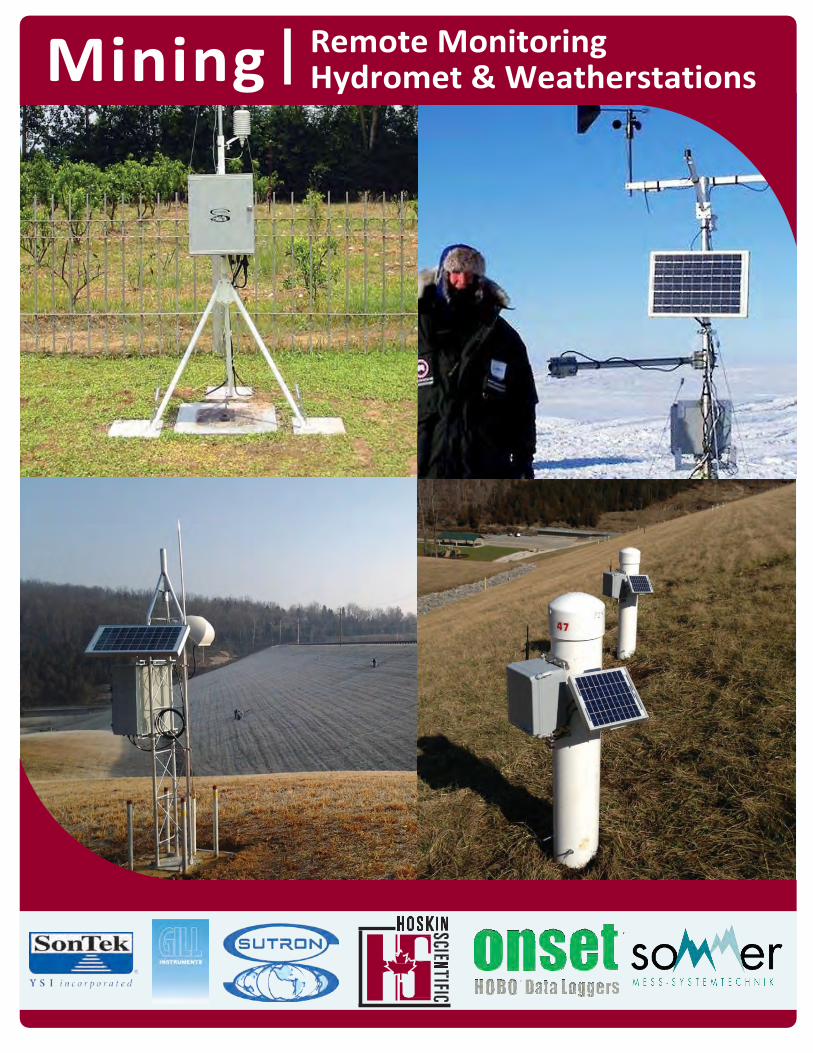
Mining Remote Monitoring Hydromet & Weatherstations

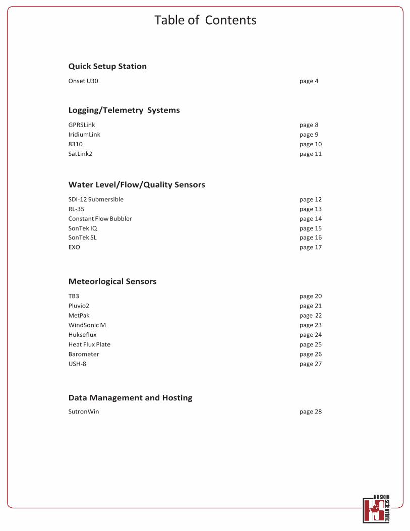
Table of Contents
Quick Setup Station
Onset U30 page 4
Logging/Telemetry Systems
GPRSLink page 8 IridiumLink page 9 8310 page 10 SatLink2 page 11
Water Level/Flow/Quality Sensors
SDI-12 Submersible page 12 RL-35 page 13 Constant Flow Bubbler page 14 SonTek IQ page 15 SonTek SL page 16 EXO page 17
Meteorlogical Sensors
TB3 page 20 Pluvio2 page 21 MetPak page 22 WindSonic M page 23 Hukseflux page 24 Heat Flux Plate page 25 Barometer page 26 USH-8 page 27
Data Management and Hosting SutronWin page 28
4
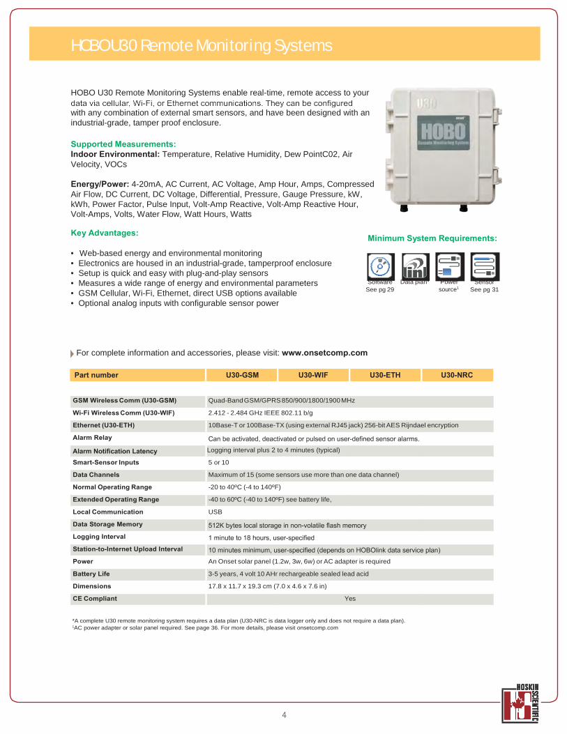
HOBO U30 Remote Monitoring Systems enable real-time, remote access to your
with any combination of external smart sensors, and have been designed with an industrial-grade, tamper proof enclosure.
Supported Measurements: Indoor Environmental: Temperature, Relative Humidity, Dew PointC02, Air Velocity, VOCs
Energy/Power: 4-20mA, AC Current, AC Voltage, Amp Hour, Amps, Compressed Air Flow, DC Current, DC Voltage, Differential, Pressure, Gauge Pressure, kW, kWh, Power Factor, Pulse Input, Volt-Amp Reactive, Volt-Amp Reactive Hour, Volt-Amps, Volts, Water Flow, Watt Hours, Watts
Key Advantages:
• Web-based energy and environmental monitoring • Electronics are housed in an industrial-grade, tamperproof enclosure • Setup is quick and easy with plug-and-play sensors
Minimum System Requirements:
• Measures a wide range of energy and environmental parameters • GSM Cellular, Wi-Fi, Ethernet, direct USB options available • Optional analog inputs with configurable sensor power
Software See pg 29
Data plan* Power source1
Sensor See pg 31
For complete information and accessories, please visit: www.onsetcomp.com
Part number U30-GSM U30-WIF U30-ETH U30-NRC
GSM Wireless Comm (U30-GSM) Quad-Band GSM/GPRS 850/900/1800/1900 MHz
Wi-Fi Wireless Comm (U30-WIF) 2.412 - 2.484 GHz IEEE 802.11 b/g
Ethernet (U30-ETH) 10Base-T or 100Base-TX (using external RJ45 jack) 256-bit AES Rijndael encryption
Alarm Relay
Logging interval plus 2 to 4 minutes (typical)
Smart-Sensor Inputs 5 or 10
Data Channels Maximum of 15 (some sensors use more than one data channel)
Normal Operating Range -20 to 40ºC (-4 to 140ºF)
Extended Operating Range -40 to 60ºC (-40 to 140ºF) see battery life,
Local Communication USB
Data Storage Memory
Logging Interval
Station-to-Internet Upload Interval
Power An Onset solar panel (1.2w, 3w, 6w) or AC adapter is required
Battery Life 3-5 years, 4 volt 10 AHr rechargeable sealed lead acid
Dimensions 17.8 x 11.7 x 19.3 cm (7.0 x 4.6 x 7.6 in)
CE Compliant Yes
*A complete U30 remote monitoring system requires a data plan (U30-NRC is data logger only and does not require a data plan). 1AC power adapter or solar panel required. See page 36. For more details, please visit onsetcomp.com
HOBO U30 Remote Monitoring Systems
5
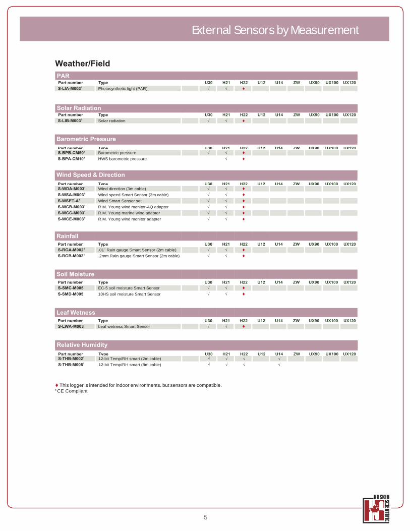
Weather/Field
Part number Type U30 H21 H22 U12 U14 ZW UX90 UX100 UX120 S-LIA-M0031 Photosynthetic light (PAR) √ √
Part number Type U30 H21 H22 U12 U14 ZW UX90 UX100 UX120 S-LIB-M0031 Solar radiation √ √
Barometric Pressure Part number Type U30 H21 H22 U12 U14 ZW UX90 UX100 UX120 S-BPB-CM501 Barometric pressure √ √ S-BPA-CM101 HWS barometric pressure √
Wind Speed & Direction Part number Type U30 H21 H22 U12 U14 ZW UX90 UX100 UX120 S-WDA-M0031 Wind direction (3m cable) √ √ S-WSA-M0031 Wind speed Smart Sensor (3m cable) √ √ S-WSET-A1 Wind Smart Sensor set √ √ S-WCB-M0031 R.M. Young wind monitor-AQ adapter √ √ S-WCC-M0031 R.M. Young marine wind adapter √ √ S-WCE-M0031 R.M. Young wind monitor adapter √ √
Rainfall Part number Type U30 H21 H22 U12 U14 ZW UX90 UX100 UX120 S-RGA-M0021 .01” Rain gauge Smart Sensor (2m cable) √ √ S-RGB-M0021 .2mm Rain gauge Smart Sensor (2m cable) √ √
Soil Moisture Part number Type U30 H21 H22 U12 U14 ZW UX90 UX100 UX120 S-SMC-M005 EC-5 soil moisture Smart Sensor √ √ S-SMD-M005 10HS soil moisture Smart Sensor √ √
Leaf Wetness Part number Type U30 H21 H22 U12 U14 ZW UX90 UX100 UX120 S-LWA-M003 Leaf wetness Smart Sensor √ √
Relative Humidity Part number Type U30 H21 H22 U12 U14 ZW UX90 UX100 UX120 S-THB-M0021 12-bit Temp/RH smart (2m cable) √ √ √ √ S-THB-M0081 12-bit Temp/RH smart (8m cable) √ √ √ √
This logger is intended for indoor environments, but sensors are compatible. 1 CE Compliant
External Sensors by Measurement
PAR
Solar Radiation
6
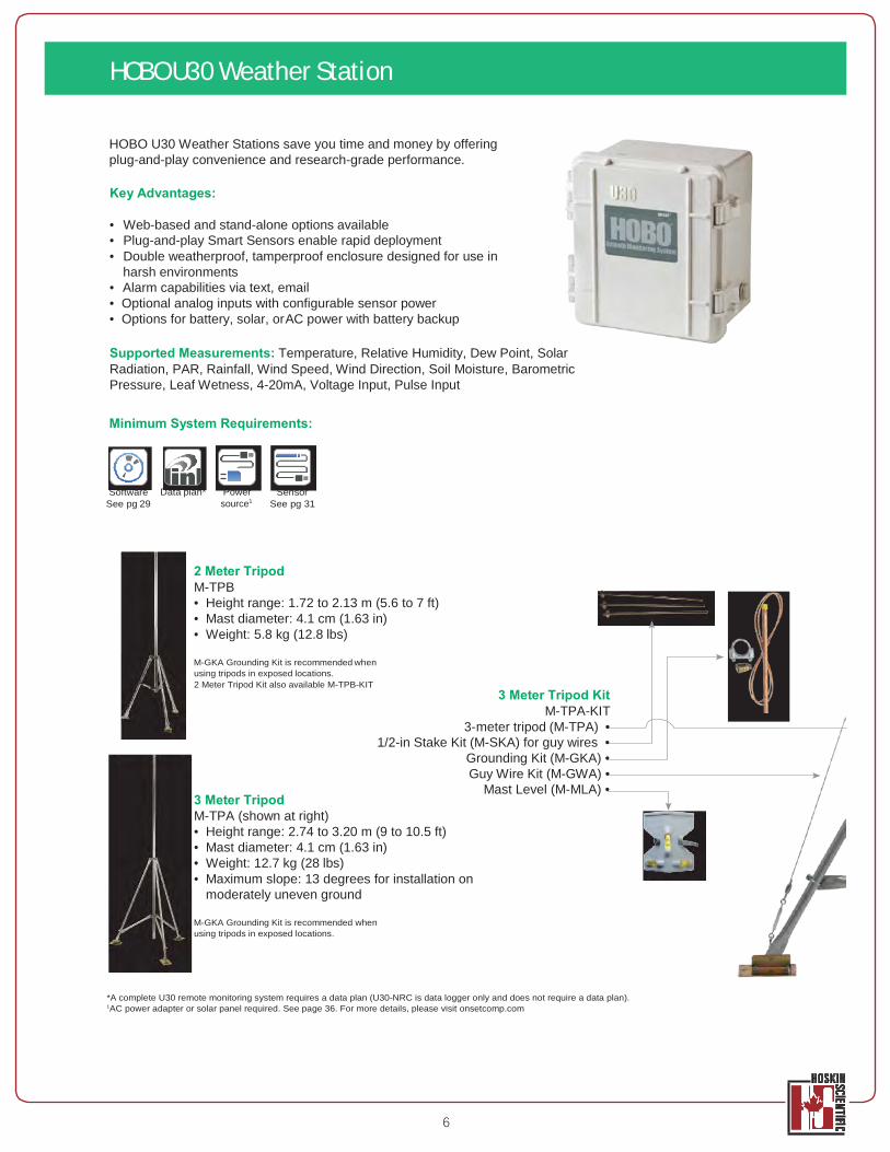
HOBO U30 Weather Stations save you time and money by offering plug-and-play convenience and research-grade performance.
Key Advantages:
• Web-based and stand-alone options available • Plug-and-play Smart Sensors enable rapid deployment • Double weatherproof, tamperproof enclosure designed for use in
harsh environments • Alarm capabilities via text, email • Optional analog inputs with configurable sensor power • Options for battery, solar, or AC power with battery backup
Supported Measurements: Temperature, Relative Humidity, Dew Point, Solar Radiation, PAR, Rainfall, Wind Speed, Wind Direction, Soil Moisture, Barometric Pressure, Leaf Wetness, 4-20mA, Voltage Input, Pulse Input
Minimum System Requirements:
Software See pg 29
Data plan* Power source1
Sensor See pg 31
2 Meter Tripod M-TPB • Height range: 1.72 to 2.13 m (5.6 to 7 ft) • Mast diameter: 4.1 cm (1.63 in) • Weight: 5.8 kg (12.8 lbs)
M-GKA Grounding Kit is recommended when using tripods in exposed locations. 2 Meter Tripod Kit also available M-TPB-KIT
3 Meter Tripod M-TPA (shown at right)
3 Meter Tripod Kit M-TPA-KIT
3- meter tripod (M-TPA) • 1/2-in Stake Kit (M-SKA) for guy wires •
Grounding Kit (M-GKA) • Guy Wire Kit (M-GWA) •
Mast Level (M-MLA) •
• Height range: 2.74 to 3.20 m (9 to 10.5 ft) • Mast diameter: 4.1 cm (1.63 in) • Weight: 12.7 kg (28 lbs) • Maximum slope: 13 degrees for installation on
moderately uneven ground
M-GKA Grounding Kit is recommended when using tripods in exposed locations.
*A complete U30 remote monitoring system requires a data plan (U30-NRC is data logger only and does not require a data plan). 1AC power adapter or solar panel required. See page 36. For more details, please visit onsetcomp.com
HOBO U30 Weather Station
Bracket
M-LBB screws
ounting.
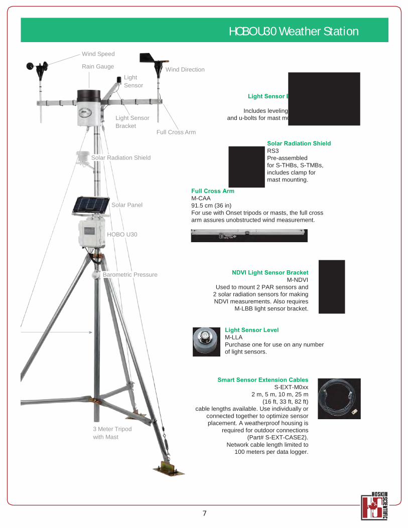
Wind Speed
Rain Gauge
Light Sensor
Wind Direction
Light Sensor
Light Sensor Bracket
Solar Radiation Shield
Full Cross Arm
Includes leveling and u-bolts for mast m
Solar Radiation Shield RS3 Pre-assembled for S-THBs, S-TMBs, includes clamp for mast mounting.
Solar Panel
Full Cross Arm M-CAA 91.5 cm (36 in) For use with Onset tripods or masts, the full cross arm assures unobstructed wind measurement.
HOBO U30
Barometric Pressure
NDVI Light Sensor Bracket M-NDVI
Used to mount 2 PAR sensors and 2 solar radiation sensors for making NDVI measurements. Also requires
M-LBB light sensor bracket.
Light Sensor Level M-LLA Purchase one for use on any number of light sensors.
3 Meter Tripod with Mast
Smart Sensor Extension Cables S-EXT-M0xx
2 m, 5 m, 10 m, 25 m (16 ft, 33 ft, 82 ft)
cable lengths available. Use individually or connected together to optimize sensor placement. A weatherproof housing is
required for outdoor connections (Part# S-EXT-CASE2).
Network cable length limited to 100 meters per data logger.
7
HOBO U30 Weather Station
22400 Davis Drive Sterling, VA 20164 (703) 406-2800 (703) 406-2801 Fax www.sutron.com [email protected] page 1 GS-25F604D SBSA NESDIS Cer r r r r
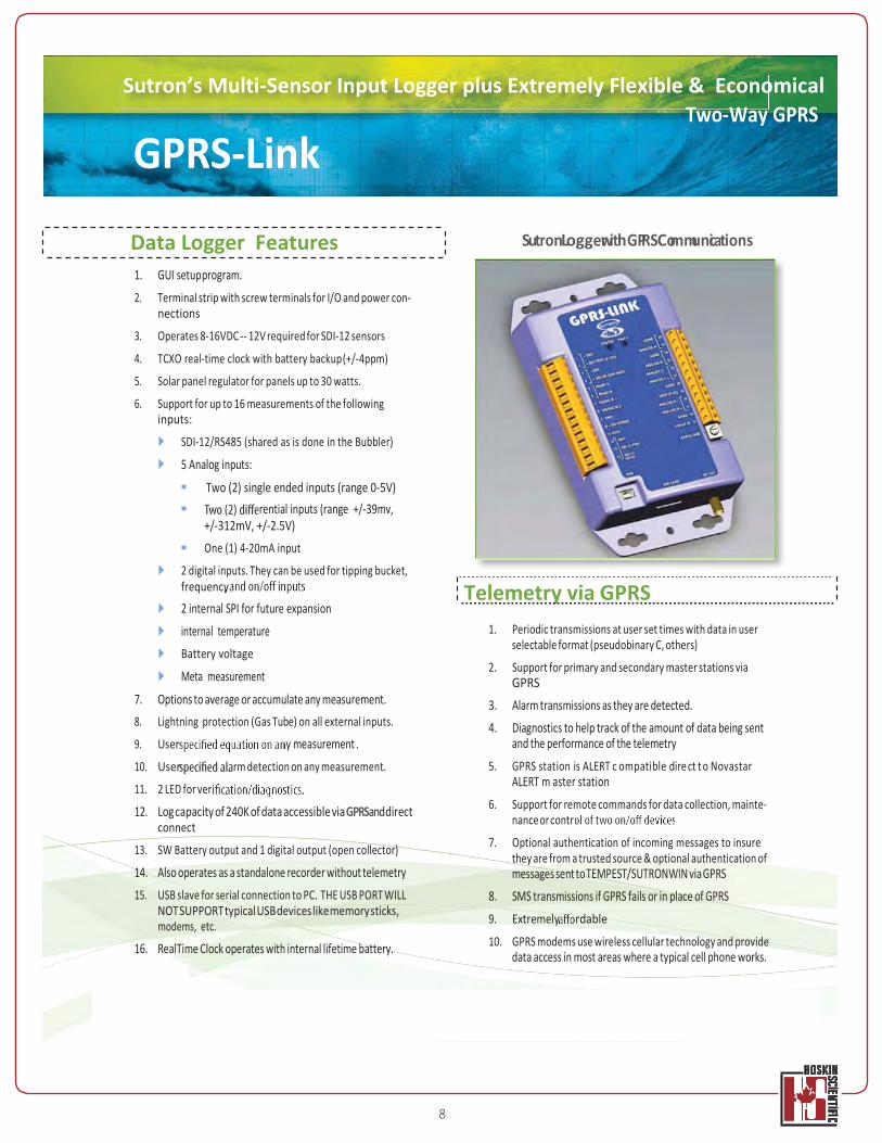
Sutron’s Multi-Sensor Input Logger plus Extremely Flexible & Economical Two-Way GPRS
GPRS-Link
Data Logger Features 1. GUI setup program. 2. Terminal strip with screw terminals for I/O and power con-
nections
3. Operates 8-16VDC -- 12V required for SDI-12 sensors
4. TCXO real-time clock with battery backup (+/-4ppm)
5. Solar panel regulator for panels up to 30 watts.
6. Support for up to 16 measurements of the following inputs:
SDI-12/RS485 (shared as is done in the Bubbler)
5 Analog inputs:
Two (2) single ended inputs (range 0-5V) rential inputs (range +/-39mv,
+/-312mV, +/-2.5V) One (1) 4-20mA input
SutronLoggewr ithGPRSCommunciations
2 digital inputs. They can be used for tipping bucket, frequency
2 internal SPI for future expansion internal temperature Battery voltage
Meta measurement
7. Options to average or accumulate any measurement. 8. Lightning protection (Gas Tube) on all external inputs.
9. User y measurement . 10. User rm detection on any measurement.
11. 2 LED for ver
12. Log capacity of 240K of data accessible via GPRSand direct connect
13. SW Battery output and 1 digital output (open collector)
14. Also operates as a standalone recorder without telemetry 15. USB slave for serial connection to PC. THE USB PORT WILL
NOT SUPPORT typical USB devices like memory sticks, modems, etc.
16. RealTime Clock operates with internal lifetime battery.
Telemetry via GPRS 1. Periodic transmissions at user set times with data in user
selectable format (pseudobinary C, others)
2. Support for primary and secondary master stations via GPRS
3. Alarm transmissions as they are detected. 4. Diagnostics to help track of the amount of data being sent
and the performance of the telemetry 5. GPRS station is ALERT c ompatible dire ct t o Novastar
ALERT m aster station
6. Support for remote commands for data collection, mainte- nance or contr
7. Optional authentication of incoming messages to insure they are from a trusted source & optional authentication of messages sent to TEMPEST/SUTRONWIN via GPRS
8. SMS transmissions if GPRS fails or in place of GPRS 9. Extremely rdable
10. GPRS modems use wireless cellular technology and provide data access in most areas where a typical cell phone works.
8
9
P R
E L I
MIN
AR
Y
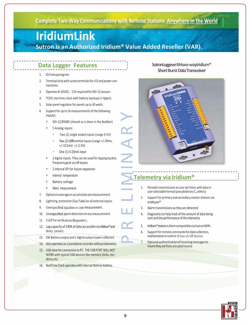
Complete Two-Way Communications with Remote Stations Anywhere in the World
IridiumLink Sutron is an Authorized Iridium® Value Added Reseller (VAR).
Data Logger Features 1. GUI setup program.
2. Terminal strip with screw terminals for I/O and power con- nections
3. Operates 8-16VDC -- 12V required for SDI-12 sensors
4. TCXO real-time clock with battery backup (+/-4ppm)
5. Solar panel regulator for panels up to 30 watts.
6. Support for up to 16 measurements of the following inputs:
SDI-12/RS485 (shared as is done in the Bubbler)
5 Analog inputs:
Two (2) single ended inputs (range 0-5V)
rential inputs (range +/-39mv, +/-312mV, +/-2.5V)
One (1) 4-20mA input 2 digital inputs. They can be used for tipping bucket, frequency
2 internal SPI for future expansion internal temperature Battery voltage
Meta measurement 7. Options to average or accumulate any measurement.
8. Lightning protection (Gas Tube) on all external inputs.
9. User y measurement . 10. User rm detection on any measurement.
11. 2 LED for ver
12. Log capacity of 240K of data accessible via Iridium®and direct connect
13. SW Battery output and 1 digital output (open collector)
14. Also operates as a standalone recorder without telemetry 15. USB slave for connection to PC. THE USB PORT WILL NOT
WORK with typical USB devices like memory sticks, mo- dems, etc.
16. RealTime Clock operates with internal lifetime battery.
SutronLoggewr ithtwo-wayIridium® Short Burst Data Transceiver
Telemetry via Iridium® 1. Periodic transmissions at user set times with data in
user selectable format (pseudobinary C, others) 2. Support for primary and secondary master stations via
Iridium® 3. Alarm transmissions as they are detected. 4. Diagnostics to help track of the amount of data being
sent and the performance of the telemetry
5. Iridium®station is Alert compatible via SutronWIN. 6. Support for remote commands for data collection,
maintenance or contr 7. Optional authentication of incoming messages to
insure they are from a trusted source
10
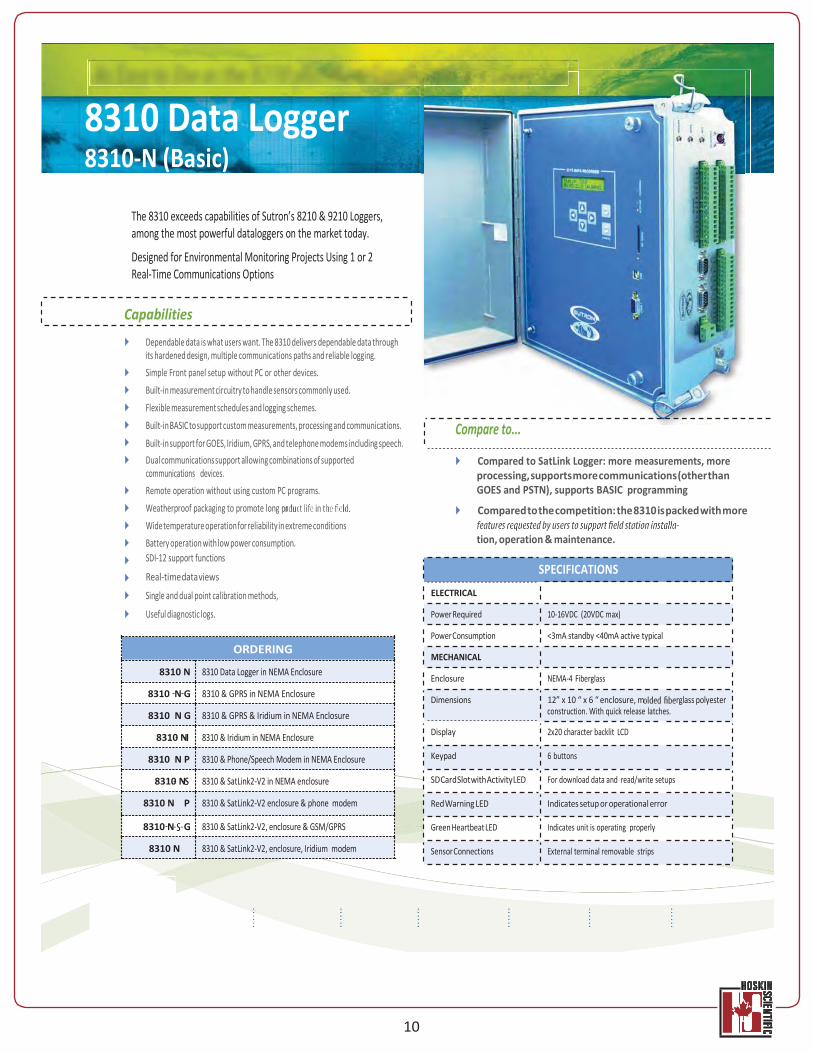
8310 Data Logger 8310-N (Basic)
The 8310 exceeds capabilities of Sutron’s 8210 & 9210 Loggers, among the most powerful dataloggers on the market today.
Designed for Environmental Monitoring Projects Using 1 or 2 Real-Time Communications Options
Capabilities
Dependable data is what users want. The 8310 delivers dependable data through its hardened design, multiple communications paths and reliable logging. Simple Front panel setup without PC or other devices. Built-in measurement circuitry to handle sensors commonly used. Flexible measurement schedules and logging schemes. Built-in BASIC to support custom measurements, processing and communications.
Compare to... Built-in support for GOES, Iridium, GPRS, and telephone modems including speech. Dual communications support allowing combinations of supported communications devices. Remote operation without using custom PC programs. Weatherproof packaging to promote long pr Wide temperature operation for reliability in extreme conditions Battery operation with low power consumption. SDI-12 support functions
Compared to SatLink Logger: more measurements, more processing, supports more communications (other than GOES and PSTN), supports BASIC programming
Compared to the competition: the 8310 is packed with more
tion, operation & maintenance.
Real-time data views SPECIFICATIONS
Single and dual point calibration methods,
Useful diagnostic logs.
ELECTRICAL
Power Required 10-16VDC (20VDC max)
Power Consumption <3mA standby <40mA active typical
MECHANICAL
Enclosure NEMA-4 Fiberglass
Dimensions 12” x 10 “ x 6 “ enclosure, m rglass polyester
construction. With quick release latches.
Display 2x20 character backlit LCD
Keypad 6 buttons
SD Card Slot with Activity LED For download data and read/write setups
Red Warning LED Indicates setup or operational error
Green Heartbeat LED Indicates unit is operating properly
Sensor Connections External terminal removable strips
ORDERING 8310 N 8310 Data Logger in NEMA Enclosure
8310 N G 8310 & GPRS in NEMA Enclosure 8310 N G 8310 & GPRS & Iridium in NEMA Enclosure
8310 N 8310 & Iridium in NEMA Enclosure 8310 N P 8310 & Phone/Speech Modem in NEMA Enclosure
8310 N 8310 & SatLink2-V2 in NEMA enclosure 8310 N P 8310 & SatLink2-V2 enclosure & phone modem 8310 N G 8310 & SatLink2-V2, enclosure & GSM/GPRS
8310 N 8310 & SatLink2-V2, enclosure, Iridium modem
11
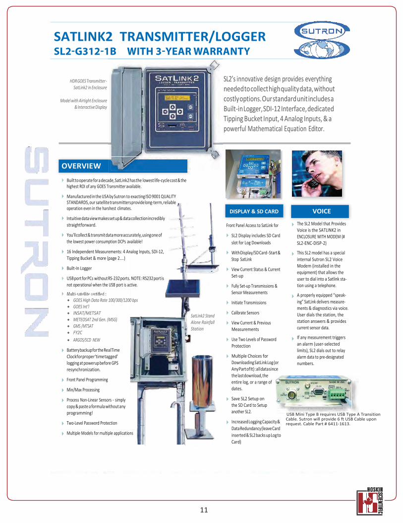
SATLINK2 TRANSMITTER/LOGGER
HDR GOES Transmitter - SatLink2 in Enclosure
Model with Airtight Enclosure
& Interactive Display
SL2’s innovative design provides everything needed to collect high quality data, without costly options. Our standard unit includes a Built-in Logger, SDI-12 Interface, dedicated Tipping Bucket Input, 4 Analog Inputs, & a powerful Mathematical Equation Editor.
OVERVIEW
Built to operate for a decade, SatLink2 has the lowest life-cycle cost & the highest ROI of any GOES Transmitter available.
Manufactured in the USA by Sutron to exacting ISO 9001 QUALITY STANDARDS, our satellite transmitters provide long-term, reliable operation even in the harshest climates.
Intuitive data view makes set up & data collection incredibly straightforward.
You’ll collect & transmit data more accurately, using one of the lowest power consumption DCPs available!
16 Independent Measurements: 4 Analog Inputs, SDI-12, Tipping Bucket & more (page 2....)
Built-In Logger
USB port for PCs without RS-232 ports. NOTE: RS232 port is not operational when the USB port is active.
GOES High Data Rate 100/300/1200 bps GOES Int’l INSAT/METSAT METEOSAT 2nd Gen. (MSG) GMS /MTSAT FY2C ARGOS/SCD NEW
Battery backup for the Real Time Clock for proper ‘time tagged’ logging at powerup before GPS resynchronization.
Front Panel Programming
Min/Max Processing
Process Non-Linear Sensors - simply copy & paste a formula without any programming!
Two-Level Password Protection
Multiple Models for multiple applications
SatLink2 Stand Alone Rainfall Station
Front Panel Access to SatLink for
SL2 Display includes SD Card slot for Log Downloads
With Display/SD Card - Start & Stop SatLink
View Current Status & Current Set-up
Fully Set-up Transmissions & Sensor Measurements
Initiate Transmissions
Calibrate Sensors
View Current & Previous Measurements
Use Two Levels of Password Protection
Multiple Choices for Downloading SatLink Log (or Any Part of It) : all data since the last download, the entire log, or a range of dates.
Save SL2 Setup on the SD Card to Setup another SL2.
Increased Logging Capacity & Data Redundancy (leave Card inserted & SL2 backs up Log to Card)
The SL2 Model that Provides Voice is the SATLINK2 in ENCLOSURE WITH MODEM (# SL2-ENC-DISP-2)
This SL2 model has a special internal Sutron SL2 Voice Modem (installed in the equipment) that allows the user to dial into a Satlink sta- tion using a telephone.
A properly equipped “speak- ing” SatLink delivers measure- ments & diagnostics via voice. User dials the station, the station answers & provides current sensor data.
If any measurement triggers an alarm (user-selected limits), SL2 dials out to relay alarm data to pre-designated numbers.
USB Mini Type B requires USB Type A Transition Cable. Sutron will provide 6 ft USB Cable upon request. Cable Part # 6411-1613.
VOICE DISPLAY & SD CARD
Well Seal with Battery Access, RS-232, and Aux Power Connections
Cable Strain Relief
Cable
Aquistar PT2x Pressure Datalogger AA powered
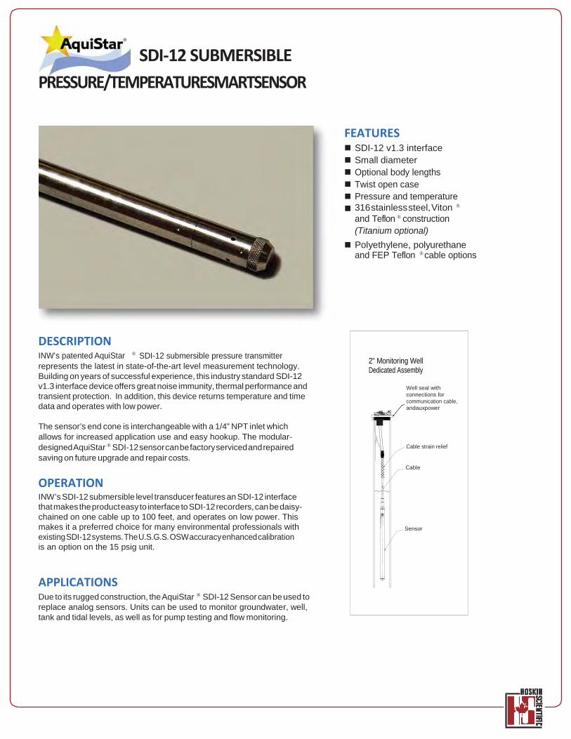
SDI-12 SUBMERSIBLE PRESSURE/TEMPERATURESMARTSENSOR
FEATURES SDI-12 v1.3 interface Small diameter Optional body lengths Twist open case Pressure and temperature 316 stainless steel, Viton ®
and Teflon ® construction (Titanium optional) Polyethylene, polyurethane and FEP Teflon ® cable options
DESCRIPTION INW’s patented AquiStar
® SDI-12 submersible pressure transmitter represents the latest in state-of-the-art level measurement technology. Building on years of successful experience, this industry standard SDI-12 v1.3 interface device offers great noise immunity, thermal performance and transient protection. In addition, this device returns temperature and time data and operates with low power.
The sensor’s end cone is interchangeable with a 1/4” NPT inlet which allows for increased application use and easy hookup. The modular- designed AquiStar ® SDI-12 sensor can be factory serviced and repaired saving on future upgrade and repair costs.
OPERATION INW’s SDI-12 submersible level transducer features an SDI-12 interface that makes the product easy to interface to SDI-12 recorders, can be daisy- chained on one cable up to 100 feet, and operates on low power. This makes it a preferred choice for many environmental professionals with existing SDI-12 systems. The U.S.G.S. OSW accuracy enhanced calibration is an option on the 15 psig unit.
APPLICATIONS Due to its rugged construction, the AquiStar ® SDI-12 Sensor can be used to replace analog sensors. Units can be used to monitor groundwater, well, tank and tidal levels, as well as for pump testing and flow monitoring.
2" Monitoring Well Dedicated Assembly
Well seal with connections for communication cable, andauxpower
Cable strain relief
Cable
Sensor
I n s t r u m e nt at i o n N o r t h w es t , I nc . A q uiStar 2 0 0 0 0-P T30 P S I G
M ADE I N REDM
O ND, W A USA-
PATENT# 5 033 297
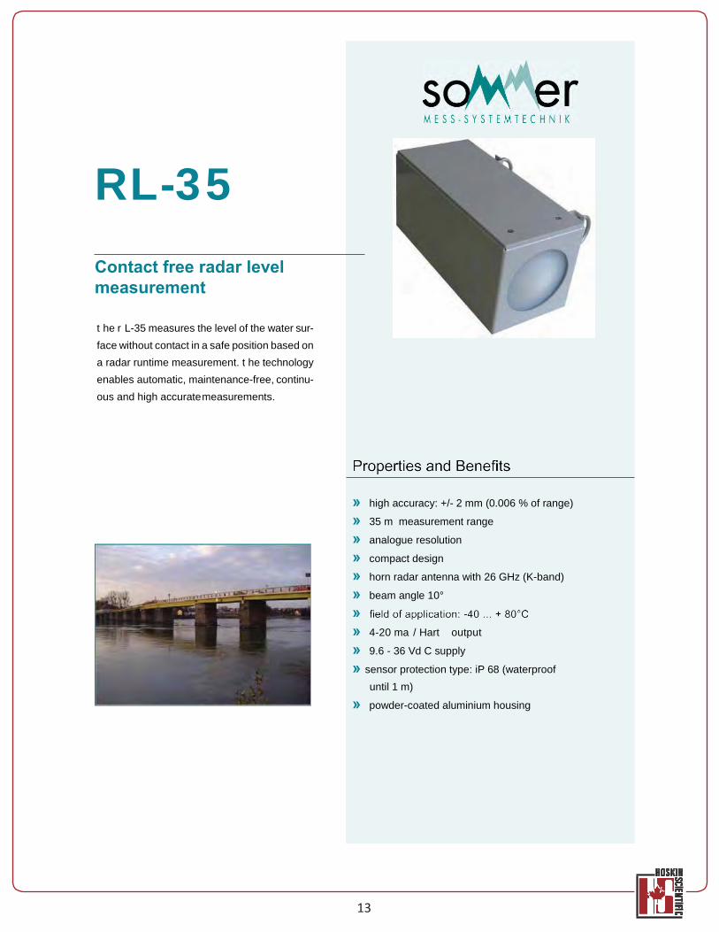
RL-35 Contact free radar level measurement
t he r L-35 measures the level of the water sur- face without contact in a safe position based on a radar runtime measurement. t he technology enables automatic, maintenance-free, continu- ous and high accurate measurements.
» high accuracy: +/- 2 mm (0.006 % of range)
» 35 m measurement range
» analogue resolution
» compact design
» horn radar antenna with 26 GHz (K-band)
» beam angle 10°
» » 4-20 ma / Hart output
» 9.6 - 36 Vd C supply
» sensor protection type: iP 68 (waterproof until 1 m)
» powder-coated aluminium housing
13
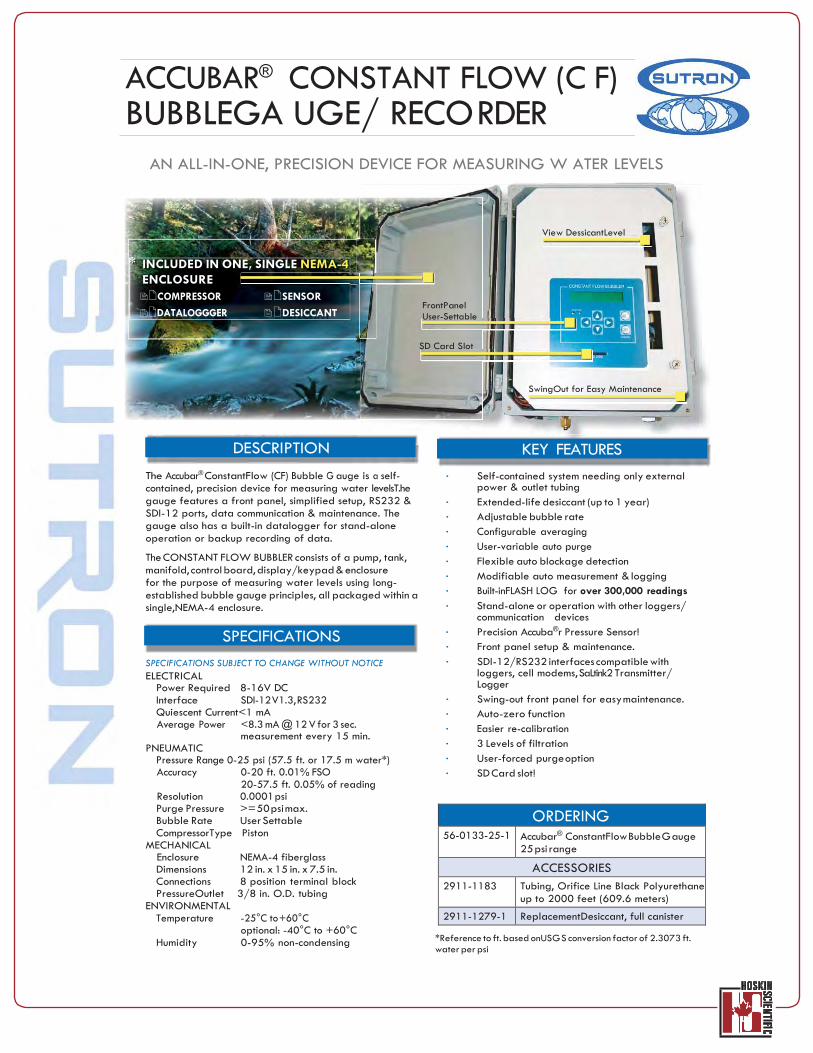
ACCUBAR® CONSTANT FLOW (C F) BUBBLEGA UGE/ RECO RDER
AN ALL-IN-ONE, PRECISION DEVICE FOR MEASURING W ATER LEVELS
* INCLUDED IN ONE, SINGLE NEMA-4 ENCLOSURE COMPRESSOR SENSOR
DATALOGGGER DESICCANT
FrontPanel User-Settable
View DessicantLevel
SD Card Slot
SwingOut for Easy Maintenance
DESCRIPTION
The Accubar® ConstantFlow (CF) Bubble G auge is a self- contained, precision device for measuring water levelsT.he gauge features a front panel, simplified setup, RS232 & SDI-12 ports, data communication & maintenance. The gauge also has a built-in datalogger for stand-alone operation or backup recording of data.
The CONSTANT FLOW BUBBLER consists of a pump, tank, manifold, control board, display/keypad & enclosure for the purpose of measuring water levels using long- established bubble gauge principles, all packaged within a single,NEMA-4 enclosure.
SPECIFICATIONS SPECIFICATIONS SUBJECT TO CHANGE WITHOUT NOTICE ELECTRICAL
Power Required 8-16V DC Interface SDI-12 V1.3, RS232 Quiescent Current<1 mA Average Power <8.3 mA @ 12 V for 3 sec.
measurement every 15 min. PNEUMATIC
Pressure Range 0-25 psi (57.5 ft. or 17.5 m water*) Accuracy 0-20 ft. 0.01% FSO
20-57.5 ft. 0.05% of reading Resolution 0.0001 psi Purge Pressure >= 50 psi max. Bubble Rate User Settable CompressorType Piston
MECHANICAL Enclosure NEMA-4 fiberglass Dimensions 12 in. x 15 in. x 7.5 in. Connections 8 position terminal block PressureOutlet 3/8 in. O.D. tubing
ENVIRONMENTAL Temperature -25°C to +60°C
optional: -40°C to +60°C Humidity 0-95% non-condensing
KEY FEATURES • Self-contained system needing only external
power & outlet tubing • Extended-life desiccant (up to 1 year) • Adjustable bubble rate • Configurable averaging • User-variable auto purge • Flexible auto blockage detection • Modifiable auto measurement & logging • Built-inFLASH LOG for over 300,000 readings • Stand-alone or operation with other loggers/
communication devices • Precision Accuba®r Pressure Sensor! • Front panel setup & maintenance. • SDI-12/RS232 interfaces compatible with
loggers, cell modems, SaLtink2 Transmitter/ Logger
• Swing-out front panel for easy maintenance. • Auto-zero function • Easier re-calibration • 3 Levels of filtration • User-forced purge option • SD Card slot!
ORDERING 56-0133-25-1 Accubar® ConstantFlow Bubble G auge
25 psi range ACCESSORIES
2911-1183 Tubing, Orifice Line Black Polyurethane up to 2000 feet (609.6 meters)
2911-1279-1 ReplacementDesiccant, full canister *Reference to ft. based onUSG S conversion factor of 2.3073 ft. water per psi
SonTek-IQ Standard, Plus and Pipe
FLOW, TOTAL VOLUME, LEVEL AND VELOCITY
Whether you need just a practical and cost-effective solution for a single canal, or you operate a large public utility with dozens of monitoring sites, there’s a SonTek-IQ right for your application. Simply input the channel geometry using the intuitive SonTek-IQ software and you are outputting accurate flow data in minutes!
SonTek-IQ Standard : Big Quality for Small Budgets The SonTek-IQ Standard version is a “no frills” option for the budget-minded operator. But with the SonTek-IQ Standard, low budgets do not mean low quality data! Using the same powerful SmartPulseHD technology that is used in the SonTek-IQ Plus system, you won’t be sacrificing quality while monitoring your flow.
The Standard version allows measurement for depths up to 1.5 m in open-channels only, and basic data parameters output for display or export based on a dynamic, single integrated velocity cell.
SonTek-IQ Plus: Monitoring in Complex Environments
The SonTek-IQ Plus version offers a flow monitoring solution for larger canals and natural environments with depths up to 5 m. With the ability to collect velocity profiling data in cells as small as 2 cm across a channel horizontally and vertically, this version offers the user complete flexibility in applications and detailed flow velocity parameters for those times when “just flow” isn’t enough.
The SonTek-IQ Plus is capable of handling not just regular trapezoidal canals, but any irregular/naturally-shaped channel, up to 5 m deep, where flow, velocity and/or level need to be measured. And with the flexibility of the SonTek-IQ software, the opportunities are endless.
SonTek-IQ Pipe: Accurate Flow in Totally or Partially Full Pipes
The SonTek-IQ Pipe is intended as either a bottom or top mounted flow meter that can be used in most industrial or agricultural applications. Unlike many other flow meters available today, the SonTek-IQ Pipe automatically determines if the pipe is full or partially full, and identifies the best technique to use to measure the velocity of the water. This information is then used to compute flow, along with accurate water level data provided by the vertical beam and/or pressure sensor. All this without additional configuration.
With a special form factor, the SonTek-IQ Pipe can provide accurate flow values in pipes from 0.5 all the way to 5.0 m, independent of whether these pipes are full or have only a few inches of water in them.
visit sontek.com/iq
15
TM
Argonaut - SL S i d e - L o o k i n g Do p p le r C ur r en t Meter
Argonaut-SL in the Field
Applications s River Discharge Monitoring s Irrigation Canals s Ports and Harbors s Shallow Streams and Estuaries s Water Supply
Features s Water Velocity and Level s MultiCell Current Profiling s PowerPing Hi-precision Sampling s Mounting and Display, and I/O s Velocity-Indexing Software
SL3000
SL1500
SL500
Sampling
Range1 Minimum
Channel Width
Acoustics -Horizontal Beam Width2
-Vertical Beam Width2
-Side Lobe
Suppression3 PowerPing Hi-
Precision
SonTek TrueCompass/Tilt
Water Level -Vertical Beam Range
-Accuracy
-Pressure Sensor
-Wave Height Spectra
Power -Input
-
Consumption4 Physical -Weight in Air
-Weight in Water
-Pressure Rating (Max Depth)
0.1 to 5m (0.3 to 17 ft) 0.2 to 20m (0.7 to 66 ft) 1.5 to 120m (5 to 400 ft) 0.75m (2.5 ft) 1.50m (5 ft) 6.5m (21 ft)
1.4º
1.4º 1.4º
1.4º 2.9º 3.8º >60dB >60dB >60dB n/a
n/a
0.1 to 5.0 m (0.3 to 17 ft)
0.15 to 10m (0.5 to 33 ft)
0.2 to 18.0m (0.7 to 59 ft) (depth < 3 m): ±0.3 cm (0.01 ft) (depth > 3 meters): ± 0.1%
(depth < 3 m): ±0.3 cm (0.01 ft) (depth > 3 meters): ±0.1%
(depth < 6 m): ±0.6 cm (0.02 ft) (depth > 6 meters): ±0.1%
n/a 0.25% 0.25% n/a Optional Optional
7-15 VDC
7-15 VDC
7-15 VDC
0.5 – 0.7 W 0.5 – 0.7 W 0.7 – 1.0 W
1.2 kg (2.6 lb)
2.4 kg (5.3 lb)
6 kg (13.2 lb) 0.3 kg (0.7 lb) 0.2 kg (0.5 lb) 1.1 kg (2.5 lb) 30 m (98 ft) 30 m (98 ft) 30 m (98 ft)
28 x 25 x 1 cm (11" x 8" x 0.4”)
Integrated Mount 35.5 x 22.9 x 1.5 cm
(14” x 9” x 0.6”)
1 Actual Maximum range depends on environmental conditions 2 Full beam width reported at half power level (-3dB) 3 Side lobe suppression improves the aspect ratio of the instrument enabling greater measurement range in shallower water. 4 Power consumption will be higher with PowerPing and/or Flow Display enabled
1
&90 - "EWBODFE 8BUFS 2VBMJUZ .POJUPSJOH 1MBUGPSN
WBUFS RVBMJUZ NPOJUPSJOH UIBt’T mFME-SFBEZ
4VSGBDF WBUFS & GSPVOE WBUFS .oOJUoSJOH CBQUVSJOH BDDVSBUF EBUB JO GSFTIXBUFS FOWJSPONFOUT JT FBTZ XJUI &X0.
0VU PG UIF Cox, &X0 JT SFBEZ UP HP XJUI: t PSF-JOTUBMMFE TFOTPST GPS FBTZ TFU-VQ PG
GBDUPSZ-DPOmHVSFE TZTUFNT t 8JSFMFTT DPNNVOJDBUJPO SFEVDFT OVNCFS PG
mFME DBCMFT t 0OCPBSE EJBHOPTUJDT NJUJHBUF TFU-VQ BOE
DPOmHVSBUJPO FSSPST
EXO1 sonde t 4VSGBDF BOE
HSPVOEXBUFS NPOJUPSJOH EPXO UP 250 N (828 GU)
t #MVFUPPUI XJSFMFTT DPNNVOJDBUJPO
t 2VJDL BOE FBTZ DBMJCSBUJPO PG NVMUJQMF TFOTPST
t WFMEFE UJUBOJVN TFOTPST JODMVEJOH DPOEVDUJWJUZ, EJTTPMWFE oYZHFO, G%0., Q), 03P, UVSCJEJUZ, BOE UPUBM BMHBF
EXO2 sonde t C5% QMVT 3-5
BEEJUJPOBM TFOTPST t CPBTUBM BOE NBSJOF
NPOJUPSJOH EPXO UP 250 N (828 GU)
t 4FBNMFTT JOUFHSBUJPO BOE “EBJTZ DIBJOJOHw JOUP NPOJUPSJOH TZTUFNT
t 'MFYJCMF TFOTPS QBZMoBE/DPOmHVSBtJPOT t WFMEFE UJUBOJVN
TFOTPST t "OUJGPVMJOH XJQFS
IFMQT UP FYUFOE EFQMPZNFOUT UP NPSF UIBO 90 EBZT
8JUI B IJHIMZ FGmDJFOU QPXFS NBOBHFNFOU QMBUGPSN, SPCVTU DPOTUSVDUJPO, BOE B DIFNJTUSZ-GSFF BOUJ-GPVMJOH TZTUFN, &X0 BMMPXT BDDVSBUF EBUB DPMMFDUJPO GPS VQ UP 90 EBZT CFUXFFO TFSWJDF JOUFSWBMT.
17
18
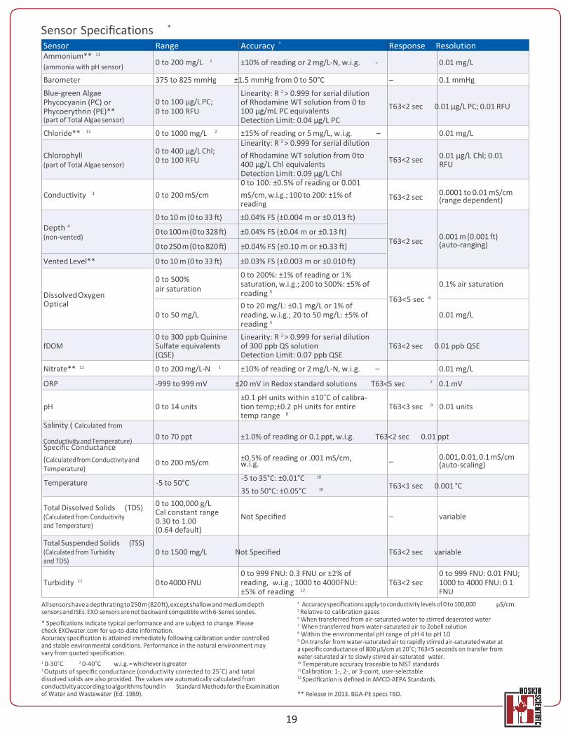
Instrument Specifications *
EXO1 Sonde Ports 4 sensor ports
Peripheral port: 1 power communication port Size Diameter: 4.70 cm (1.85 in)
Length: 64.77 cm (25.50 in) Weight 1.42 kg (3.15 lbs) with 4 probes, guard and batteries installed EXO2 Sonde Ports 7 sensor ports (6 ports available when central wiper used)
Peripheral ports: 1 power communication port; 1 auxiliary expansion port Size Diameter: 7.62 cm (3.00 in)
Length: 71.10 cm (28.00 in) Weight 3.60 kg (7.90 lbs) with 5 probes, guard and batteries installed Sondes Operating Temperature -5 to 50˚C Storage Temperature -20 to 80˚C (except 0 to 60˚C for pH and pH/ORP sensors) Depth Rating 0 to 250 m (0 to 820 ft) Communications Computer Interface: Bluetooth wireless technology, RS-485, USB
Output Options: USB with signal output adapter (SOA); RS-232 & SDI-12 with DCP-SOA Sample Rate Up to 4 Hz Battery Life 90 days ** Data Memory 512 MB total memory; >1,000,000 logged readings Sensors Calculated Parameters Ammonium ** ORP Salinity Chloride ** pH Specific Conductance Conductivity Temperature Total Dissolved Solids Depth Total Algae (Chlorophyll + BGA-PC or PE **) Total Suspended Solids Dissolved Oxygen Turbidity Fluorescent Dissolved Organic Matter (fDOM) Vented Level **
Nitrate ** EXO Handheld Size Width: 12.00 cm (4.72 in)
Height: 25.00 cm (9.84 in) Weight 0.71 kg (1.56 lbs) without batteries Operating System Windows CE 5.0 Operating Temperature -10 to 50˚C Storage Temperature -20 to 80˚C IP Rating IP-67 Data Memory 2 GB total memory; >2,000,000 data sets Accessories Cables (non-vented) Flow cells Sonde/sensor guard Carrying case KOR software Calibration cup DCP Signal Output Adapter USB Signal Output Adapter Anti-fouling components Warranty 1 Year pH, ORP, and optical DO membranes
2 Years Cables, sondes (bulkheads), handheld, and the following sensors: conductivity, temperature, depth, and optical sensors
* Specifications indicate typical performance and are subject to change. Please check EXOwater.com for up-to-date information. ** Typically 90 days at 20˚C at 15-minute logging interval; temperature/conductivity, pH/ ORP, DO, and turbidity sensors installed on EXO1; or temperature/conductivity, pH/ORP, DO, total algae, and turbidity sensors installed with central wiper that rotates once per logging interval on EXO2. Battery life is heavily dependent on sensor configuration.
EXO Bluetooth modules comply with Part 15C of FCC Rules and have FCC, CE Mark and C-tick approval. Bluetooth-type approvals and regulations can be country specific. Check local laws and regulations to insure that the use of wireless products purchased from Xylem are in full compliance. ** Release in 2013. BGA-PE specs TBD.
19
Sensor Specifications *
Sensor Range Accuracy * Response Resolution Ammonium** 11
(ammonia with pH sensor) 0 to 200 mg/L ±10% of reading or 2 mg/L-N, w.i.g. - 0.01 mg/L
Barometer 375 to 825 mmHg ±1.5 mmHg from 0 to 50°C – 0.1 mmHg Blue-green Algae Phycocyanin (PC) or Phycoerythrin (PE)** (part of Total Algae sensor)
0 to 100 μg/L PC; 0 to 100 RFU
Linearity: R 2 > 0.999 for serial dilution of Rhodamine WT solution from 0 to 100 μg/mL PC equivalents Detection Limit: 0.04 μg/L PC
T63<2 sec 0.01 μg/L PC; 0.01 RFU
Chloride** 11 0 to 1000 mg/L 2 ±15% of reading or 5 mg/L, w.i.g. – 0.01 mg/L Linearity: R 2 > 0.999 for serial dilution
Chlorophyll (part of Total Algae sensor)
0 to 400 μg/L Chl; 0 to 100 RFU of Rhodamine WT solution from 0 to
400 μg/L Chl equivalents Detection Limit: 0.09 μg/L Chl 0 to 100: ±0.5% of reading or 0.001
T63<2 sec 0.01 μg/L Chl; 0.01 RFU
Conductivity 3 0 to 200 mS/cm mS/cm, w.i.g.; 100 to 200: ±1% of reading
T63<2 sec 0.0001 to 0.01 mS/cm (range dependent)
Depth 4
(non-vented)
0 to 10 m (0 to 33 ft) ±0.04% FS (±0.004 m or ±0.013 ft)
0 to 100 m (0 to 328 ft) ±0.04% FS (±0.04 m or ±0.13 ft)
0 to 250 m (0 to 820 ft) ±0.04% FS (±0.10 m or ±0.33 ft)
T63<2 sec 0.001 m (0.001 ft)
(auto-ranging)
Vented Level** 0 to 10 m (0 to 33 ft) ±0.03% FS (±0.003 m or ±0.010 ft)
Dissolved Oxygen Optical
0 to 500% air saturation
0 to 50 mg/L
0 to 300 ppb Quinine
0 to 200%: ±1% of reading or 1% saturation, w.i.g.; 200 to 500%: ±5% of reading 5
0 to 20 mg/L: ±0.1 mg/L or 1% of reading, w.i.g.; 20 to 50 mg/L: ±5% of reading 5
Linearity: R 2 > 0.999 for serial dilution
T63<5 sec 6
0.1% air saturation
0.01 mg/L
fDOM Sulfate equivalents (QSE)
of 300 ppb QS solution Detection Limit: 0.07 ppb QSE
T63<2 sec 0.01 ppb QSE
Nitrate** 11 0 to 200 mg/L-N 1 ±10% of reading or 2 mg/L-N, w.i.g. – 0.01 mg/L
ORP -999 to 999 mV ±20 mV in Redox standard solutions T63<5 sec 7 0.1 mV
±0.1 pH units within ±10˚C of calibra- pH 0 to 14 units
Salinity ( Calculated from
tion temp;±0.2 pH units for entire temp range 8
T63<3 sec 9 0.01 units
Conductivity and Temperature) 0 to 70 ppt ±1.0% of reading or 0.1 ppt, w.i.g. T63<2 sec 0.01 ppt Specific Conductance (Calculated from Conductivity and Temperature)
0 to 200 mS/cm ±0.5% of reading or .001 mS/cm, w.i.g. – 0.001, 0.01, 0.1 mS/cm
(auto-scaling)
Temperature -5 to 50°C -5 to 35°C: ±0.01°C 10
35 to 50°C: ±0.05°C 10
T63<1 sec 0.001 °C
Total Dissolved Solids (TDS) (Calculated from Conductivity and Temperature)
Total Suspended Solids (TSS)
0 to 100,000 g/L Cal constant range 0.30 to 1.00 (0.64 default)
Not Specified – variable
(Calculated from Turbidity and TDS)
0 to 1500 mg/L Not Specified T63<2 sec variable
Turbidity 11 0 to 4000 FNU
0 to 999 FNU: 0.3 FNU or ±2% of reading, w.i.g.; 1000 to 4000 FNU: ±5% of reading 12
T63<2 sec
0 to 999 FNU: 0.01 FNU; 1000 to 4000 FNU: 0.1 FNU
All sensors have a depth rating to 250 m (820 ft), except shallow and medium depth sensors and ISEs. EXO sensors are not backward compatible with 6-Series sondes.
* Specifications indicate typical performance and are subject to change. Please check EXOwater.com for up-to-date information. Accuracy specification is attained immediately following calibration under controlled and stable environmental conditions. Performance in the natural environment may vary from quoted specification. 1 0-30˚C 2 0-40˚C w.i.g. = whichever is greater 3 Outputs of specific conductance (conductivity corrected to 25˚C) and total dissolved solids are also provided. The values are automatically calculated from conductivity according to algorithms found in Standard Methods for the Examination of Water and Wastewater (Ed. 1989).
4 Accuracy specifications apply to conductivity levels of 0 to 100,000 μS/cm. 5 Relative to calibration gases 6 When transferred from air-saturated water to stirred deaerated water 7 When transferred from water-saturated air to Zobell solution 8 Within the environmental pH range of pH 4 to pH 10 9 On transfer from water-saturated air to rapidly stirred air-saturated water at a specific conductance of 800 μS/cm at 20˚C; T63<5 seconds on transfer from water-saturated air to slowly-stirred air-saturated water. 10 Temperature accuracy traceable to NIST standards 11 Calibration: 1-, 2-, or 3-point, user-selectable 12 Specification is defined in AMCO-AEPA Standards
** Release in 2013. BGA-PE specs TBD.
1
Bulletin 52, Edition 2
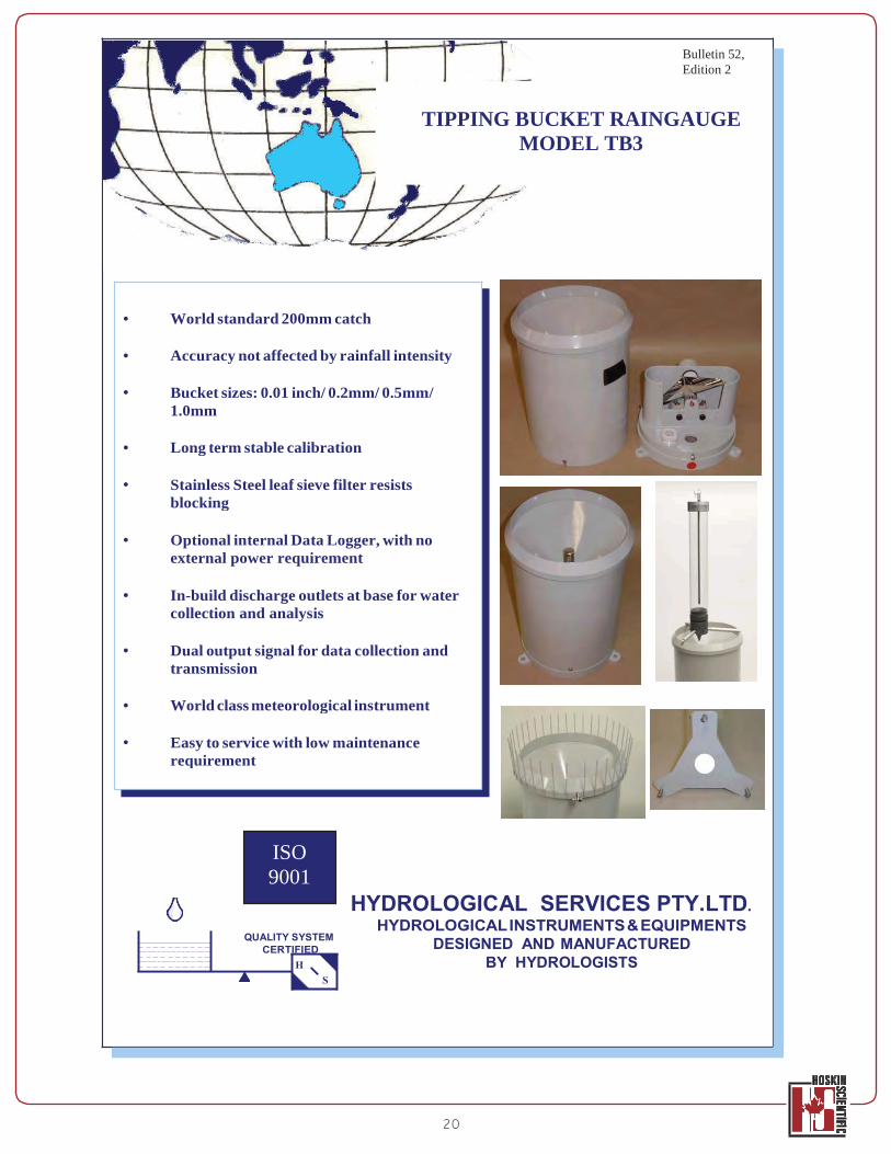
TIPPING BUCKET RAINGAUGE MODEL TB3
QUALITY SYSTEM CERTIFIED
HYDROLOGICAL SERVICES PTY.LTD. HYDROLOGICAL INSTRUMENTS & EQUIPMENTS
DESIGNED AND MANUFACTURED BY HYDROLOGISTS
20
• World standard 200mm catch
• Accuracy not affected by rainfall intensity
• Bucket sizes: 0.01 inch/ 0.2mm/ 0.5mm/ 1.0mm
• Long term stable calibration
• Stainless Steel leaf sieve filter resists blocking
• Optional internal Data Logger, with no external power requirement
• In-build discharge outlets at base for water collection and analysis
• Dual output signal for data collection and transmission
• World class meteorological instrument
• Easy to service with low maintenance requirement
ISO 9001
21
22
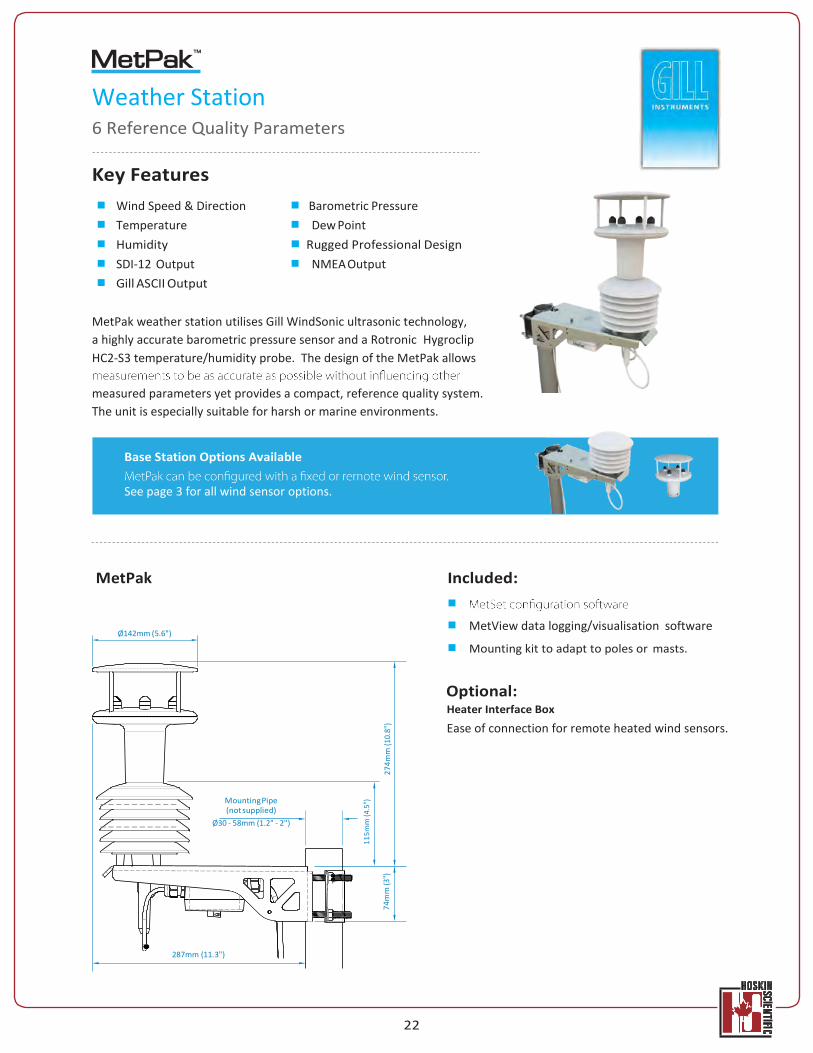
Weather Station 6 Reference Quality Parameters
Key Features
Wind Speed & Direction Barometric Pressure Temperature Dew Point Humidity Rugged Professional Design SDI-12 Output NMEA Output Gill ASCII Output
MetPak weather station utilises Gill WindSonic ultrasonic technology, a highly accurate barometric pressure sensor and a Rotronic Hygroclip HC2-S3 temperature/humidity probe. The design of the MetPak allows
measured parameters yet provides a compact, reference quality system. The unit is especially suitable for harsh or marine environments.
MetPak
Ø142mm (5.6")
Included:
MetView data logging/visualisation software
Mounting kit to adapt to poles or masts.
Optional: Heater Interface Box
Ease of connection for remote heated wind sensors.
Mounting Pipe (not supplied)
Ø30 - 58mm (1.2" - 2")
287mm (11.3")
Base Station Options Available
See page 3 for all wind sensor options.
115m
m (4
.5")
74m
m (3
")
274m
m (1
0.8"
)
23
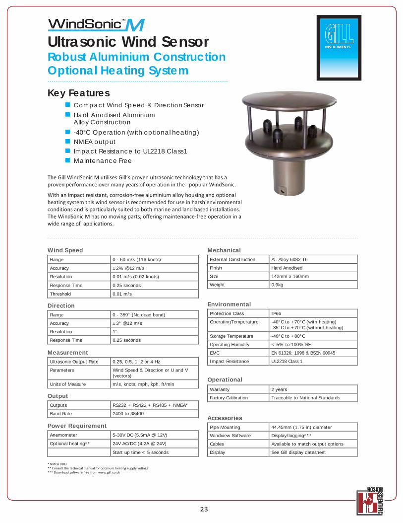
Ultrasonic Wind Sensor Robust Aluminium Construction Optional Heating System
Key Features Compact Wind Speed & Direction Sensor Hard Anodised Aluminium
Alloy Construction -40°C Operation (with optional heating) NMEA output Impact Resistance to UL2218 Class 1 Maintenance Free
The Gill WindSonic M utilises Gill’s proven ultrasonic technology that has a proven performance over many years of operation in the popular WindSonic.
With an impact resistant, corrosion-free aluminium alloy housing and optional heating system this wind sensor is recommended for use in harsh environmental conditions and is particularly suited to both marine and land based installations. The WindSonic M has no moving parts, offering maintenance-free operation in a wide range of applications.
Wind Speed
Direction
Mechanical
External Construction Al. Alloy 6082 T6 Finish Hard Anodised Size 142mm x 160mm Weight 0.9kg
Environmental
Range 0 - 359° (No dead band) Accuracy ±3° @12 m/s Resolution 1° Response Time 0.25 seconds
Measurement
Operational
Output
Accessories Power Requirement Anemometer 5-30V DC (5.5mA @ 12V) Optional heating** 24V AC/DC (4.2A @ 24V)
Start up time < 5 seconds
* NMEA 0183 ** Consult the technical manual for optimum heating supply voltage. *** Download software free from www.gill.co.uk
INSTRUMENTS
Range 0 - 60 m/s (116 knots) Accuracy ±2% @12 m/s Resolution 0.01 m/s (0.02 knots) Response Time 0.25 seconds Threshold 0.01 m/s
Protection Class IP66 OperatingTemperature -40°C to +70°C (with heating)
-35°C to +70°C (without heating) Storage Temperature -40°C to +80°C Operating Humidity < 5% to 100% RH EMC EN 61326: 1998 & BSEN 60945 Impact Resistance UL2218 Class 1
Ultrasonic Output Rate 0.25, 0.5, 1, 2 or 4 Hz Parameters Wind Speed & Direction or U and V
(vectors) Units of Measure m/s, knots, mph, kph, ft/min
Warranty 2 years Factory Calibration Traceable to National Standards
Outputs RS232 + RS422 + RS485 + NMEA* Baud Rate 2400 to 38400
Pipe Mounting 44.45mm (1.75 in) diameter Windview Software Display/logging*** Cables Available to match output options Display See Gill display datasheet
24
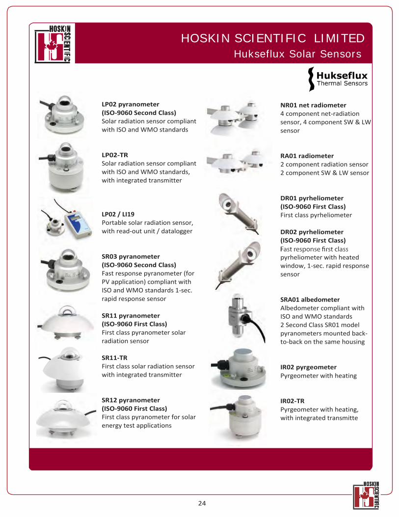
HOSKIN SCIENTIFIC LIMITED Hukseflux Solar Sensors
LP02 pyranometer (ISO-9060 Second Class) Solar radiation sensor compliant with ISO and WMO standards
LP02-TR Solar radiation sensor compliant with ISO and WMO standards, with integrated transmitter
LP02 / LI19 Portable solar radiation sensor, with read-out unit / datalogger
SR03 pyranometer (ISO-9060 Second Class) Fast response pyranometer (for PV application) compliant with ISO and WMO standards 1-sec. rapid response sensor
SR11 pyranometer (ISO-9060 First Class) First class pyranometer solar radiation sensor
SR11-TR First class solar radiation sensor with integrated transmitter
SR12 pyranometer (ISO-9060 First Class) First class pyranometer for solar energy test applications
NR01 net radiometer 4 component net-radiation sensor, 4 component SW & LW sensor
RA01 radiometer 2 component radiation sensor 2 component SW & LW sensor
DR01 pyrheliometer (ISO-9060 First Class) First class pyrheliometer
DR02 pyrheliometer (ISO-9060 First Class)
pyrheliometer with heated window, 1-sec. rapid response sensor
SRA01 albedometer Albedometer compliant with ISO and WMO standards 2 Second Class SR01 model pyranometers mounted back- to-back on the same housing
IR02 pyrgeometer Pyrgeometer with heating
IR02-TR Pyrgeometer with heating, with integrated transmitte
25
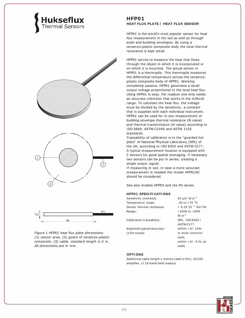
HFP01 HEAT FLUX PLATE / HEAT FLUX SENSOR
HFP01 is the world’s most popular sensor for heat flux measurement in the soil as well as through walls and building envelopes. By using a ceramics-plastic composite body the total thermal resistance is kept small.
HFP01 serves to measure the heat that flows through the object in which it is incorporated or on which it is mounted. The actual sensor in HFP01 is a thermopile. This thermopile measures the differential temperature across the ceramics- plastic composite body of HFP01. Working completely passive, HFP01 generates a small output voltage proportional to the local heat flux. Using HFP01 is easy. For readout one only needs an accurate voltmeter that works in the millivolt range. To calculate the heat flux, the voltage must be divided by the sensitivity; a constant that is supplied with each individual instrument. HFP01 can be used for in-situ measurement of building envelope thermal resistance (R-value) and thermal transmittance (H-value) according to ISO 9869, ASTM C1046 and ASTM 1155 standards. Traceability of calibration is to the “guarded hot plate” of National Physical Laboratory (NPL) of the UK, according to ISO 8302 and ASTM C177. A typical measurement location is equipped with 2 sensors for good spatial averaging. If necessary two sensors can be put in series, creating a single output signal. If measuring in soil, in case a more accurate measurement is needed the model HFP01SC should be considered.
See also models HFP03 and the PU series.
HFP01 SPECIFICATIONS Sensitivity (nominal): 50 µV/ W.m-2
Temperature range: -30 to +70 oC Sensor thermal resistance: < 6.25 10 -3 Km2/W Range : +2000 to -2000
W.m-2
Calibration traceability: NPL, ISO 8302 / ASTM C177
Expected typical accuracy: within +5/- 15% Figure 1 HFP01 heat flux plate dimensions: (1) sensor area, (2) guard of ceramics-plastic composite, (3) cable, standard length is 5 m. All dimensions are in mm.
(12hr totals) in most common soils, within +5/ -5 % on walls
OPTIONS Additional cable length x metres (add to 5m), AC100 amplifier, LI 18 hand held readout
26
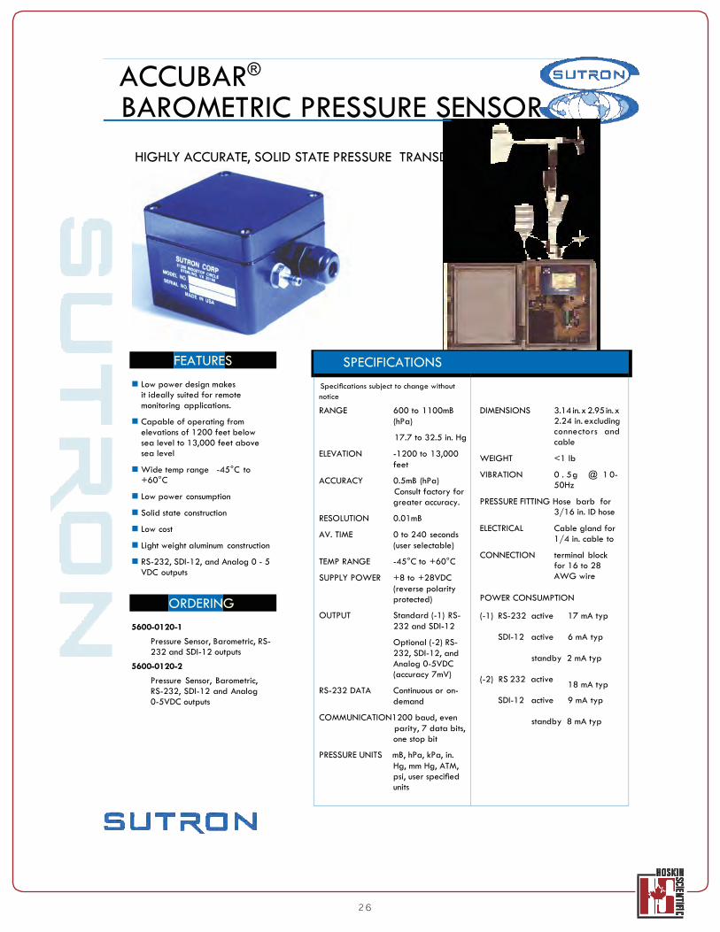
ACCUBAR®
BAROMETRIC PRESSURE SENSOR
HIGHLY ACCURATE, SOLID STATE PRESSURE TRANSDUCER
FEATURES
Low power design makes it ideally suited for remote monitoring applications.
Capable of operating from elevations of 1200 feet below sea level to 13,000 feet above sea level
Wide temp range -45°C to +60°C
Low power consumption
Solid state construction
Low cost
Light weight aluminum construction
RS-232, SDI-12, and Analog 0 - 5 VDC outputs
ORDERING
5600-0120-1
Pressure Sensor, Barometric, RS- 232 and SDI-12 outputs
5600-0120-2
Pressure Sensor, Barometric, RS-232, SDI-12 and Analog 0-5VDC outputs
SPECIFICATIONS
Specifications subject to change without
DIMENSIONS 3.14 in. x 2.95 in. x 2.24 in. excluding connectors and cable
WEIGHT <1 lb
VIBRATION 0 . 5g @ 1 0- 50Hz
PRESSURE FITTING Hose barb for 3/16 in. ID hose
ELECTRICAL Cable gland for 1/4 in. cable to
CONNECTION terminal block for 16 to 28 AWG wire
POWER CONSUMPTION
(-1) RS-232 active 17 mA typ
SDI-12 active 6 mA typ
standby 2 mA typ
(-2) RS 232 active 18 mA typ
SDI-12 active 9 mA typ
standby 8 mA typ
notice RANGE 600 to 1100mB
(hPa) 17.7 to 32.5 in. Hg
ELEVATION -1200 to 13,000 feet
ACCURACY 0.5mB (hPa) Consult factory for greater accuracy.
RESOLUTION 0.01mB AV. TIME 0 to 240 seconds
(user selectable) TEMP RANGE -45°C to +60°C SUPPLY POWER +8 to +28VDC
(reverse polarity protected)
OUTPUT Standard (-1) RS- 232 and SDI-12 Optional (-2) RS- 232, SDI-12, and Analog 0-5VDC (accuracy 7mV)
RS-232 DATA Continuous or on- demand
COMMUNICATION1200 baud, even parity, 7 data bits, one stop bit
PRESSURE UNITS mB, hPa, kPa, in. Hg, mm Hg, ATM, psi, user specified units
27
USH-8 Ultrasonic Snow Depth Sensor
Properties and Advantages
» Continuous and non-contact ultrasonic snow depth measurement
» Reliable sensor for extreme conditions • Correct measurement with snowfall and
• Automatic de-icing of the ultrasound
membrane and sensor head
» High measuring accuracy • Integrated temperature compensation • Intelligent measured signal conversion
» Energy-saving sensor operation • “Standby” between the measuring phases • Optimum for solar-powered stations
» Simple sensor integration • Analogue and digital interface • Parameterization via hyper terminal

28
Ho Real-TimeWeb Hostssting, Data Processing, Delivery, Storage & Alarms!
SutronWIN Web Hosting Water/Weather Information Network
Real-Time Web Service for Hydro-Meteorological Data Collection & Dissemination
Direct Data, Warnings & Control via the Web, in Any Format You Want, Ready to Use
Reliable Data On-Demand, Event-Triggered & Scheduled via SMS, EMAIL or ON-LINE
Telemetry Types Satellite Stations
IRIDIUM® SATELLITE STATIONS Sutron is the only IRIDIUM Value Added Reseller (VAR) in the remote environmental data collection industry. Sutron designed, developed & manufactures its own IRIDIUM® Modem for SBD Data Communications.
All Geostationary Satellite Stations Stations communicating with satellites all over the world including GOES, METEOSAT, INSAT, ARGOS, etc. Real-Time Communications Expertise is Sutron’s #1 Strength.
SutronWIN Is Designed For... Users who need a back-up server (not located in their geographi- cal area), back-up data & back-up alarms
Large System Users
Small Monitoring Systems Us- ers who don’t want the hassle odata-collection, storage, decoding, analysis, etc.
Any Users who want Sutron to simplify their data collection (which is complicated, expen-
GSM/GPRS Stations, PSTN/Modem Stations, All LOS Radio Modem Stations
sive & time consuming)
Users who want a complete, turn-key, end-to-end solution.
All Hydro-Met Applications & Stations Existing, Upgraded or New Systems
Any application where data from multiple sources needs to be seamlessly distributed to many users without interruption.
Monitoring, Warning & Control Systems
All SatelliteTransmitterData Decodedfrom Any Manufacturer including Cam ysis & Associates, YSI, For- est Technology Service, OTT, Stevens.
Advantages Hosted by Sutron
No capital investments for the Central Station
Minimal monthly recurring costs
No maintenance costs or upgrades costs
No resources required for customers
No special resources (DBA, software engineers., etc)
29
SutronWIN:Water/Weather Information Network
30
Real-Time Web Hosting, Data Processing, Delivery, Storage & Alarms!
SutronWIN Web Hosting Water/Weather Information Network
WHAT’S INCLUDED We provide all Receive Site & Server Hardware.
We activate the modems & satellite equipment. Activation of communications can be a big problem for most users. We distribute real-time data seamlessly to PCs, iPhones, Blackberries, etc.
We will develop a custom web page just for your data on SutronWIN or match your current web page styles, banner your own site. We provide a Google map or static map showing all your station sites.
We automatically perform limit checking for all your monitored parameters & derived parameters to determine if any alarms or warnings need to be issued based on your designated limits. SutronWIN will automatically generate alarms when your limits are triggered. Additionally, your author rate alarms to be sent to designated personnel on demand. Automatic alarms can be sent via voice messages, email messages & SMS. In maintenance mode, raw data messages can be sent to your cell phone, etc.
9400-0400 SutornWIN Client Set Up (one-time fee for new Web User Account)
9400-0401 Custom Starter Page (optional)
9400-0402 SutronWIN Station Set Up (one-time fee per new station)
9400-0403 SutrinWIN Per Station Annual Fee for rst 10 Stations
9400-0404 SutronWIN Service Discounted Recurring Fee for Stations 11-20
9400-0405 SutronWIN Service Discounted Recurring Fee for Stations 21-30
9400-0406 SutronWIN Service Discounted Recurring Fee for Stations 31-50

05.13
Hoskin Scientific Limited has been supplying testing and monitoring instruments since 1946. Although our range is broad, we focus on three major markets including:
Geotechnical & Materials Testing Environmental Monitoring Test & Measurement Instrumentation
Hoskin Scientific operates out of three offices within Canada:
3735 Myrtle Stree,t Burnaby, BC V5C 4E7 Phone (604) 872-7894 Fax (604) 872-0281 email [email protected] 800-663-3023
4210 Morris Drive, Burlington, ON L7L 5L6 Phone (905) 333-5510 Fax (905) 333-4976 email [email protected] 800-247-3581
300 Rue Stinson, Montreal, PQ H4N 2E7 Phone (514) 735-5267 Fax (514) 735-3454 email [email protected]