Embed Size (px)
Citation preview
SURGICAL TECHNIQUE INNOVATIONS IN MINIMALLY INVASIVEJOINT SURGERY
Minimally Invasive TKAGENESIS™ II Anterior Cut First
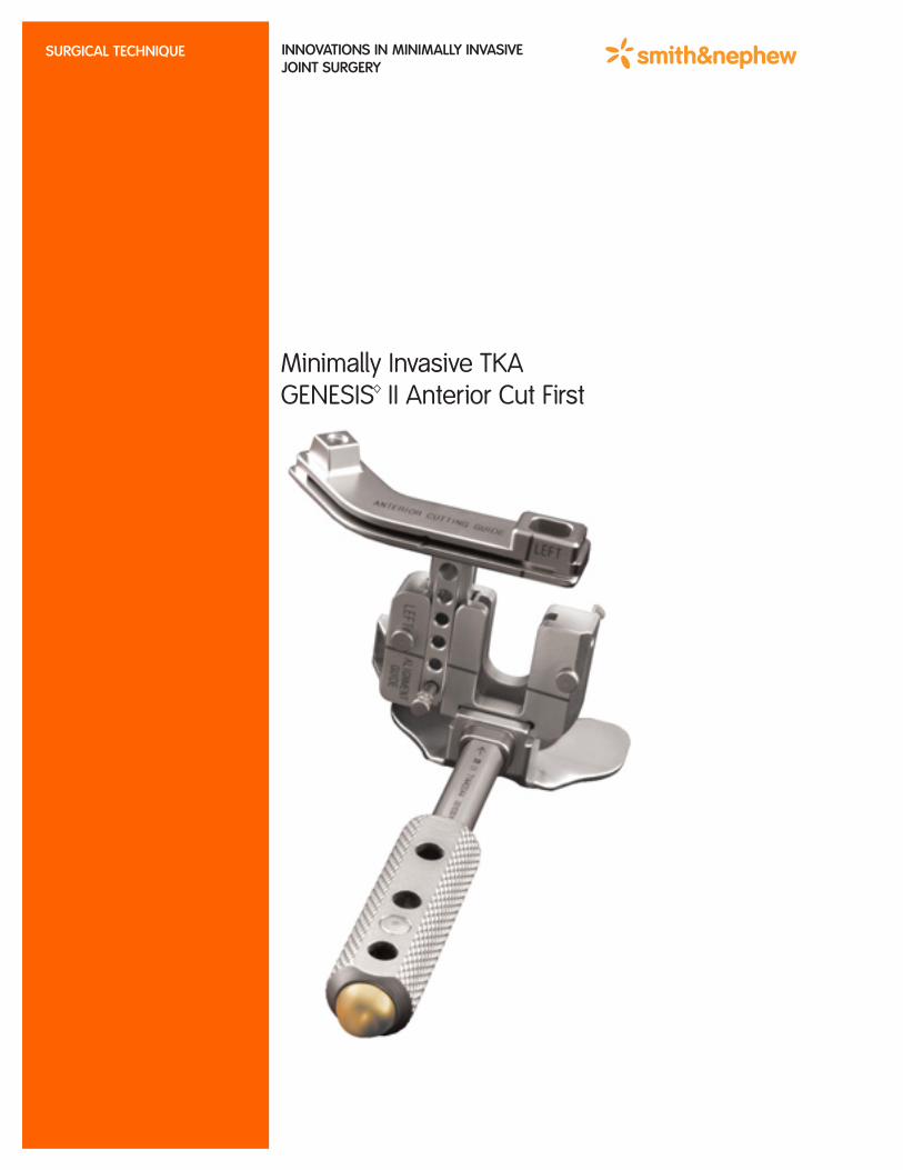
Anterior Resection Stylus71441115
Valgus AlignmentGuide Left71441111
Valgus AlignmentGuide Right71441112
Femoral AlignmentTemplate71441141
Anterior CuttingGuide Right71441117
Rotation Alignment Paddles71441163
Femoral Sizing Guide71441113
Tibial Resection Stylus71441135
Distal FemoralCutting Block71441118
Tibial CuttingBlock Left71441136
4-in-1 Cutting BlockSize 1-71441119Size 2-71441120Size 3-71441121Size 4-71441122Size 5-71441123
Distal ResectionStylus71441161
Tibial CuttingBlock Right71441137
Housing Resection BlockSize 1-71441127Size 2-71441128Size 3-71441129Size 4-71441130Size 5-71441131
Instruments
Anterior CuttingGuide Left71441116
Size 6-71441124Size 7-71441125Size 8-71441126
Size 6-71441132Size 7-71441133Size 8-71441134

1
Instruments . . . . . . . . . . . . . . . . . . . . . . . . . . . . . . . . . . . . . . . . . . IFC
Introduction . . . . . . . . . . . . . . . . . . . . . . . . . . . . . . . . . . . . . . . . . . . .2Leg PositionIncisionArthrotomyExposure
Femoral Preparation . . . . . . . . . . . . . . . . . . . . . . . . . . . . . . .3, 4, 5, 6Intramedullary Femoral AlignmentFemoral Rotational AlignmentPreliminary Anterior Femoral ResectionDistal Femoral ResectionFemoral SizingA-P Femoral Resections
Tibial Preparation . . . . . . . . . . . . . . . . . . . . . . . . . . . . . . . . . . . . . 7, 8Extramedullary Tibial AlignmentIntramedullary Tibial AlignmentTibial ResectionTibial Sizing
Patella Preparation . . . . . . . . . . . . . . . . . . . . . . . . . . . . . . . . . . . . . 9Resurfacing (Onlay) PatellaBiconvex (Inset) Patella
Posterior Stabilized Femoral Resection . . . . . . . . . . . . . . . . . . . . 10
Trial Placement . . . . . . . . . . . . . . . . . . . . . . . . . . . . . . . . . . . . . . . . .11Femoral and Tibial TrialingPatellar Trialing
Implantation and Closure . . . . . . . . . . . . . . . . . . . . . . . . . . . . . . . .12Tibial ImplantationFemoral ImplantationPatellar ImplantationInsert PlacementClosure
Nota Bene:The technique description herein is made available to the healthcare profes-sional to illustrate the author’s suggested treatment for the uncomplicated pro-cedure. In the final analysis, the preferred treatment is that which addresses theneeds of the patient.
Surgical technique described by Steven B. Haas, M.D., M.P.H.
2
Introduction
Leg PositionAppropriate leg position is crucial when performingminimally invasive total knee arthroplasty. During the procedure, the knee is flexed to 70-90°.Hyperflexion is used only intermittently for specificportions of the case, such as insertion of the tibialcomponent. To aid in holding the leg, a sandbag isplaced across from the contralateral ankle whenpositioning the patient on the table.
IncisionWith the leg fully extended, a longitudinal incisionmeasuring 9.5 to 12 centimeters (33/4 to 43/4 inches)is made over the anterior aspect of the knee alongthe medial border of the patella. The incisionextends approximately from the middle of the tibialtubercle to the proximal extent of the patella to onefinger’s breath proximal to the patella.
ArthrotomyBegin 5 millimeters medial to the tibial tubercle and extend dissection around the medial border ofthe patella. The arthrotomy is extended up to the proximal border of the patella.
The supra-patella pouch is identified, separatedfrom the underside of the tendon and preserved.
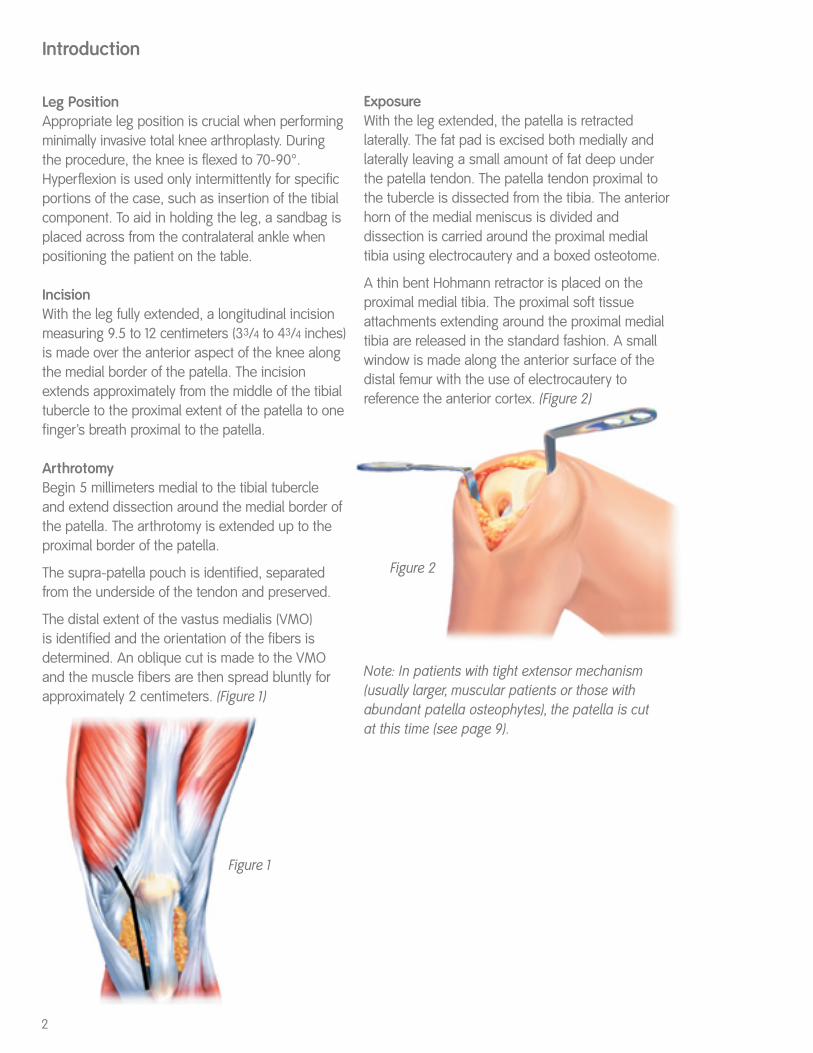
The distal extent of the vastus medialis (VMO) is identified and the orientation of the fibers is determined. An oblique cut is made to the VMOand the muscle fibers are then spread bluntly forapproximately 2 centimeters. (Figure 1)
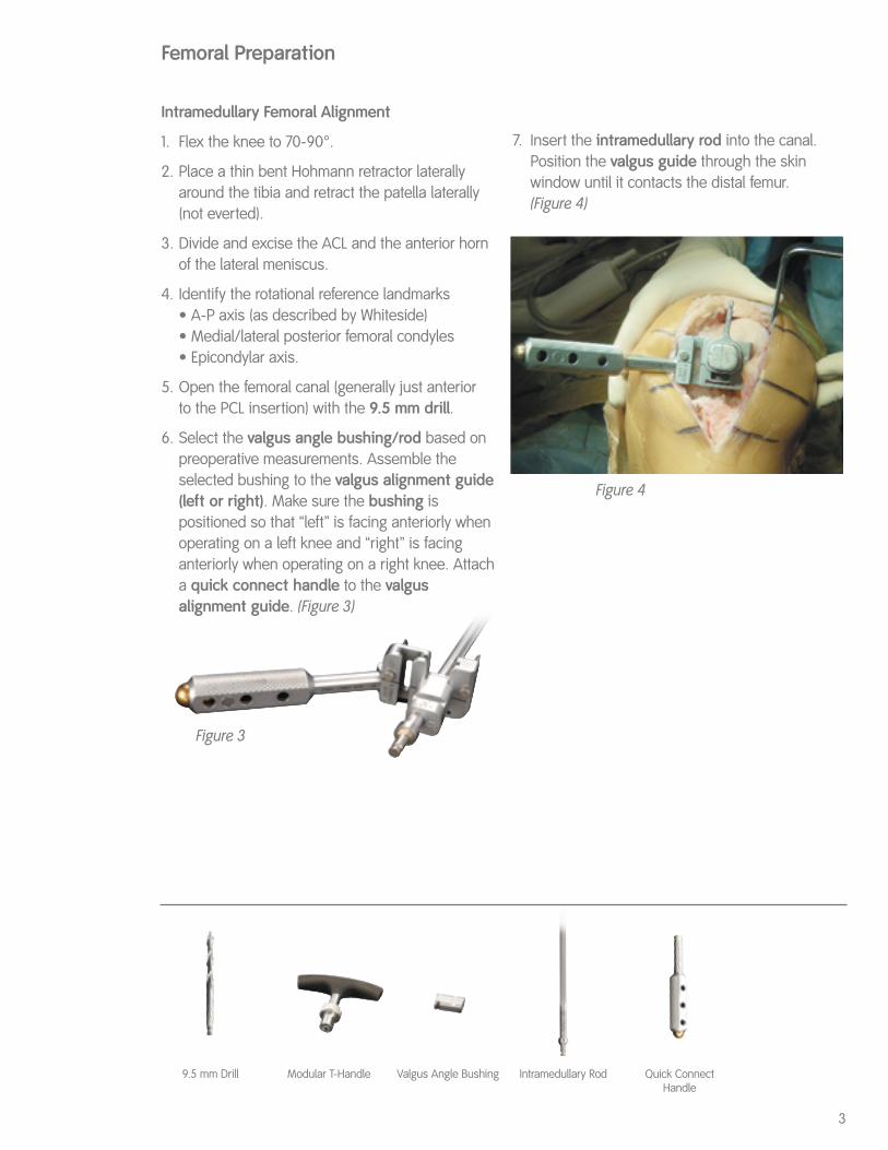
ExposureWith the leg extended, the patella is retracted laterally. The fat pad is excised both medially andlaterally leaving a small amount of fat deep underthe patella tendon. The patella tendon proximal tothe tubercle is dissected from the tibia. The anteriorhorn of the medial meniscus is divided and dissection is carried around the proximal medialtibia using electrocautery and a boxed osteotome.
A thin bent Hohmann retractor is placed on the proximal medial tibia. The proximal soft tissueattachments extending around the proximal medialtibia are released in the standard fashion. A smallwindow is made along the anterior surface of thedistal femur with the use of electrocautery to reference the anterior cortex. (Figure 2)
Note: In patients with tight extensor mechanism(usually larger, muscular patients or those withabundant patella osteophytes), the patella is cut at this time (see page 9).
Figure 1
Figure 2
3
Femoral Preparation
Figure 3
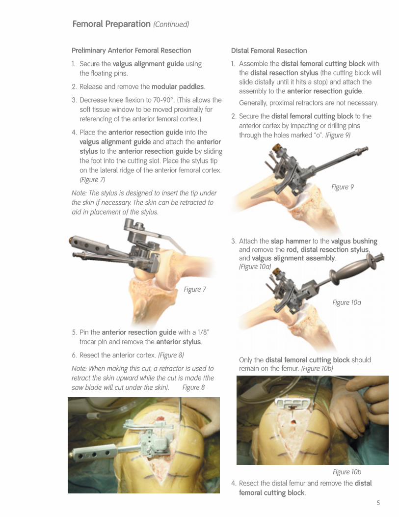
Figure 4
Quick ConnectHandle
Intramedullary Femoral Alignment
1. Flex the knee to 70-90°.
2. Place a thin bent Hohmann retractor laterallyaround the tibia and retract the patella laterally(not everted).
3. Divide and excise the ACL and the anterior hornof the lateral meniscus.
4. Identify the rotational reference landmarks• A-P axis (as described by Whiteside)• Medial/lateral posterior femoral condyles• Epicondylar axis.
5. Open the femoral canal (generally just anterior to the PCL insertion) with the 9.5 mm drill.
6. Select the valgus angle bushing/rod based onpreoperative measurements. Assemble theselected bushing to the valgus alignment guide(left or right). Make sure the bushing is positioned so that “left” is facing anteriorly whenoperating on a left knee and “right” is facinganteriorly when operating on a right knee. Attacha quick connect handle to the valgus alignment guide. (Figure 3)
7. Insert the intramedullary rod into the canal.Position the valgus guide through the skin window until it contacts the distal femur. (Figure 4)
9.5 mm Drill Modular T-Handle Valgus Angle Bushing Intramedullary Rod

With Paddles
1. Flex the knee to >100° with the patella retractedlaterally when inserting the valgus alignmentguide with the modular paddles.
2. Unlock the capture mechanism on the modularpaddles. The arm on the paddles distracts posteriorly and rotates to either side to unlock sothe anterior lip can engage the slot in the posterioraspect of the valgus alignment guide.
3. Insert the anterior lip of the paddles into the slot inthe valgus alignment guide. Rotating the armback centrally into the recess will lock the paddlesonto the valgus alignment guide.(Figure 6)
4. Position the paddles under the posterior condyles.
Note: Posterior condylar referencing may be less reli-able in knees with deficient posterior condyles (e.g.severe valgus deformity). If the posterior condyles aredeficient, the AP or epicondylar axis should be used.
4
Figure 5a
Locked Unlocked
Figure 6
Femoral Rotational AlignmentRotation of the valgus alignment guide is set neutral to the posterior femoral condyles by usingthe landmarks described above either with or without rotational alignment paddles.
Without Paddles
1. Flex the knee to 70-90°. 2. Align:
(a.) The posterior aspect of the valgus alignmentguide parallel to the posterior condyles.
(b.) The line laser-etched across the distal surfaceof the valgus alignment guide parallel to theepicondylar axis. (The line on the valgusalignment guide is drawn such that placing it parallel to the epicondylar axis aligns theguide in neutral rotation.)
(c.) The femoral alignment template (Figure 5a)with the A-P axis. (The femoral alignmenttemplate is designed such that setting it parallel to the A-P axis aligns the valgusalignment guide in neutral rotation.)
The femoral alignment template is placed over the valgus angle bushing to guide rotational align-ment. Make sure that the template is positioned so that “left” is facing out when operating on a leftknee and “right” is facing out when operating on aright knee. The valgus alignment guide is placed in neutral orientation by aligning the outrigger of the template with the A-P line.(Figure 5b)
Femoral Preparation (Continued)
5
Figure 7
Figure 8
Preliminary Anterior Femoral Resection
1. Secure the valgus alignment guide using the floating pins.
2. Release and remove the modular paddles.
3. Decrease knee flexion to 70-90°. (This allows thesoft tissue window to be moved proximally forreferencing of the anterior femoral cortex.)
4. Place the anterior resection guide into the valgus alignment guide and attach the anteriorstylus to the anterior resection guide by slidingthe foot into the cutting slot. Place the stylus tipon the lateral ridge of the anterior femoral cortex.(Figure 7)
Note: The stylus is designed to insert the tip underthe skin if necessary. The skin can be retracted toaid in placement of the stylus.
5. Pin the anterior resection guide with a 1/8” trocar pin and remove the anterior stylus.
6. Resect the anterior cortex. (Figure 8)
Note: When making this cut, a retractor is used toretract the skin upward while the cut is made (thesaw blade will cut under the skin).
Distal Femoral Resection
1. Assemble the distal femoral cutting block withthe distal resection stylus (the cutting block willslide distally until it hits a stop) and attach theassembly to the anterior resection guide.
Generally, proximal retractors are not necessary.
2. Secure the distal femoral cutting block to theanterior cortex by impacting or drilling pinsthrough the holes marked “o”. (Figure 9)
3. Attach the slap hammer to the valgus bushingand remove the rod, distal resection stylus, and valgus alignment assembly.(Figure 10a)
Only the distal femoral cutting block shouldremain on the femur. (Figure 10b)
4. Resect the distal femur and remove the distalfemoral cutting block.
Figure 9
Figure 10a
Femoral Preparation (Continued)
Figure 10b
6
Femoral SizingSize the femur using the femoral sizing guide. It may be necessary to flex the knee to position the posterior paddles on the sizing guide. (Figure 11)
For the correct size assessment, place the stylus tip on the provisional anterior cut, read the size indicated by the line across the stylus shaft (not the retention pin) and choose the smaller size ifbetween two sizes.
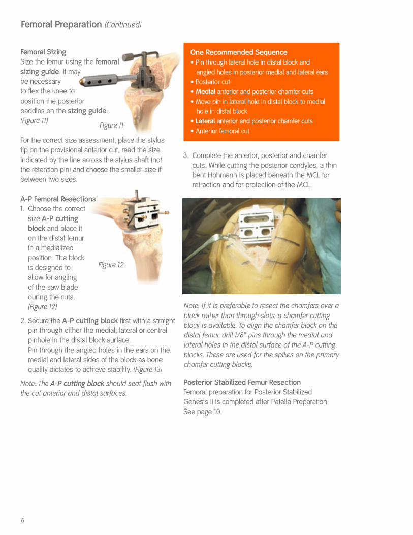
A-P Femoral Resections1. Choose the correct
size A-P cutting block and place it on the distal femur in a medialized position. The block is designed to allow for angling of the saw blade during the cuts. (Figure 12)
2. Secure the A-P cutting block first with a straightpin through either the medial, lateral or centralpinhole in the distal block surface.Pin through the angled holes in the ears on themedial and lateral sides of the block as bonequality dictates to achieve stability. (Figure 13)
Note: The A-P cutting block should seat flush withthe cut anterior and distal surfaces.
One Recommended Sequence• Pin through lateral hole in distal block and
angled holes in posterior medial and lateral ears• Posterior cut• Medial anterior and posterior chamfer cuts• Move pin in lateral hole in distal block to medial
hole in distal block• Lateral anterior and posterior chamfer cuts• Anterior femoral cut
Note: If it is preferable to resect the chamfers over ablock rather than through slots, a chamfer cuttingblock is available. To align the chamfer block on thedistal femur, drill 1/8” pins through the medial andlateral holes in the distal surface of the A-P cuttingblocks. These are used for the spikes on the primarychamfer cutting blocks.
Figure 11
Figure 12
3. Complete the anterior, posterior and chamfercuts. While cutting the posterior condyles, a thinbent Hohmann is placed beneath the MCL forretraction and for protection of the MCL.
Femoral Preparation (Continued)
Posterior Stabilized Femur ResectionFemoral preparation for Posterior Stabilized Genesis II is completed after Patella Preparation.See page 10.
7
Intramedullary TibialAlignment Guide
Tibial Preparation
Figure 14
Figure 15
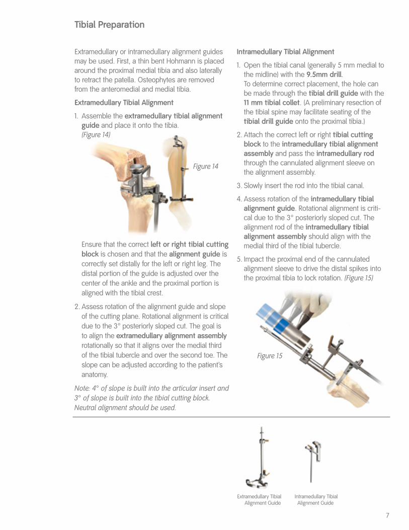
Extramedullary or intramedullary alignment guidesmay be used. First, a thin bent Hohmann is placedaround the proximal medial tibia and also laterallyto retract the patella. Osteophytes are removedfrom the anteromedial and medial tibia.
Extramedullary Tibial Alignment
1. Assemble the extramedullary tibial alignmentguide and place it onto the tibia.(Figure 14)
Ensure that the correct left or right tibial cuttingblock is chosen and that the alignment guide iscorrectly set distally for the left or right leg. Thedistal portion of the guide is adjusted over thecenter of the ankle and the proximal portion isaligned with the tibial crest.
2. Assess rotation of the alignment guide and slopeof the cutting plane. Rotational alignment is criticaldue to the 3° posteriorly sloped cut. The goal is to align the extramedullary alignment assemblyrotationally so that it aligns over the medial third of the tibial tubercle and over the second toe. Theslope can be adjusted according to the patient’sanatomy.
Note: 4° of slope is built into the articular insert and3° of slope is built into the tibial cutting block.Neutral alignment should be used.
Intramedullary Tibial Alignment
1. Open the tibial canal (generally 5 mm medial tothe midline) with the 9.5mm drill.To determine correct placement, the hole canbe made through the tibial drill guide with the11 mm tibial collet. (A preliminary resection ofthe tibial spine may facilitate seating of the tibial drill guide onto the proximal tibia.)
2. Attach the correct left or right tibial cuttingblock to the intramedullary tibial alignmentassembly and pass the intramedullary rodthrough the cannulated alignment sleeve onthe alignment assembly.
3. Slowly insert the rod into the tibial canal.
4. Assess rotation of the intramedullary tibialalignment guide. Rotational alignment is criti-cal due to the 3° posteriorly sloped cut. Thealignment rod of the intramedullary tibialalignment assembly should align with themedial third of the tibial tubercle.
5. Impact the proximal end of the cannulatedalignment sleeve to drive the distal spikes intothe proximal tibia to lock rotation. (Figure 15)
Extramedullary TibialAlignment Guide

8
Tibial Sizing
1. Determine the tibial implant size using the tibialviewing template.
2. Place the appropriate tibial drill guide or stemless tibial trial on the tibia.
3. Centralize and pin the tibial drill guide or stemless trial.
4. Drill through the stemless trial or place the 11 mm tibial collet in the drill guide and drillwith the 11 mm tibial drill.If a 9.5mm drill has been used for theintramedullary tibial alignment assembly, only the 11 mm tibial punch is needed.
5. Punch with the 11 mm tibial punch. (Figure 17)
6. Remove the tibial drill guide if used and placethe tibial trial onto the proximal tibia to assesscoverage.
Figure 17
Tibial Drill Guide 11 mm Tibial DrillTibial ViewingTemplate
11 mm Tibial Collet 11mm Tibial Punch
Tibial Preparation (Continued)
Tibial Resection
1. Attach the tibial stylus to the tibial block byinserting the stylus foot into the cutting slot.
2. Lower the cutting block until the stylus touchesthe less affected side of the tibia. This allowsplacement of the 9 mm articular insert. The stylus can also be used to adjust the depth ofthe tibia cut (adjustable to 9, 11 or 13 mm).
3. Pin the tibial cutting block to the tibia. Note thatthe cutting block sits along the medial half of the tibia. Insert pins first through the centralholes. The medial hole may also be used tosecure the tibial cutting block.
4. Remove the intramedullary alignment assemblyleaving the cutting block on the anterior tibia. Theextramedullary guide may be left in place.
5. Cut the tibia by first directing the blade in theposterior direction and then laterally.
6. Inspect the surface for any cortical ridges. Theproximal tibia can be visualized by extending theleg, placing a laminar spreader, and retractingthe patella laterally.
7. Place the leg in 90° of flexion, insert a laminarspreader and remove remnants of the medial andlateral menisci and posterior osteophytes. (Figure 16)
8. Check alignment and balance with spacer blockand rod. Balance ligaments in standard fashion.
Spacer Block
9
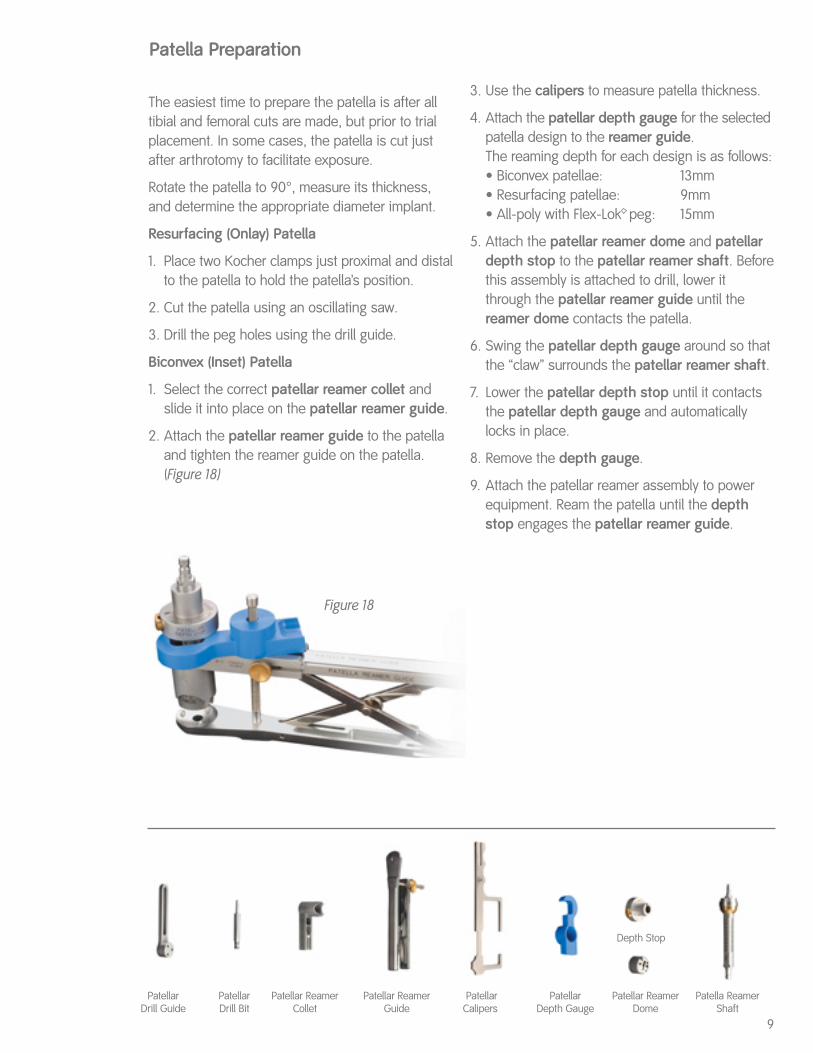
The easiest time to prepare the patella is after alltibial and femoral cuts are made, but prior to trialplacement. In some cases, the patella is cut justafter arthrotomy to facilitate exposure.
Rotate the patella to 90°, measure its thickness,and determine the appropriate diameter implant.
Resurfacing (Onlay) Patella
1. Place two Kocher clamps just proximal and distalto the patella to hold the patella’s position.
2. Cut the patella using an oscillating saw.
3. Drill the peg holes using the drill guide.
Biconvex (Inset) Patella
1. Select the correct patellar reamer collet andslide it into place on the patellar reamer guide.
2. Attach the patellar reamer guide to the patellaand tighten the reamer guide on the patella.(Figure 18)
Patella Preparation
3. Use the calipers to measure patella thickness.
4. Attach the patellar depth gauge for the selectedpatella design to the reamer guide.The reaming depth for each design is as follows:• Biconvex patellae: 13mm• Resurfacing patellae: 9mm• All-poly with Flex-Lok peg: 15mm
5. Attach the patellar reamer dome and patellardepth stop to the patellar reamer shaft. Beforethis assembly is attached to drill, lower itthrough the patellar reamer guide until thereamer dome contacts the patella.
6. Swing the patellar depth gauge around so thatthe “claw” surrounds the patellar reamer shaft.
7. Lower the patellar depth stop until it contactsthe patellar depth gauge and automaticallylocks in place.
8. Remove the depth gauge.
9. Attach the patellar reamer assembly to powerequipment. Ream the patella until the depthstop engages the patellar reamer guide.
Patellar ReamerCollet
Patellar ReamerGuide
Patellar Calipers
Patellar Depth Gauge
Depth Stop
Patellar ReamerDome
Figure 18
Patellar Drill Guide
PatellarDrill Bit
Patella Reamer Shaft
10
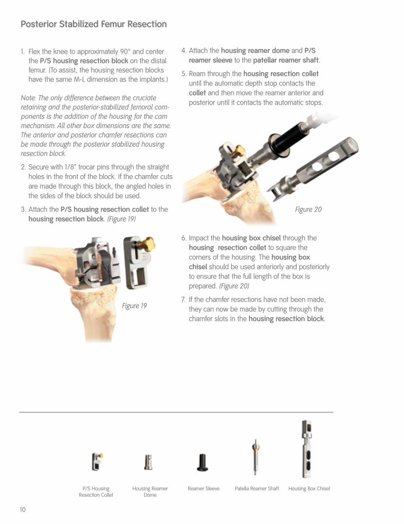
1. Flex the knee to approximately 90° and centerthe P/S housing resection block on the distalfemur. (To assist, the housing resection blockshave the same M-L dimension as the implants.)
Note: The only difference between the cruciateretaining and the posterior-stabilized femoral com-ponents is the addition of the housing for the cammechanism. All other box dimensions are the same.The anterior and posterior chamfer resections canbe made through the posterior stabilized housingresection block.
2. Secure with 1/8” trocar pins through the straightholes in the front of the block. If the chamfer cutsare made through this block, the angled holes inthe sides of the block should be used.
3. Attach the P/S housing resection collet to thehousing resection block. (Figure 19)
Posterior Stabilized Femur Resection
4. Attach the housing reamer dome and P/Sreamer sleeve to the patellar reamer shaft.
5. Ream through the housing resection colletuntil the automatic depth stop contacts the collet and then move the reamer anterior andposterior until it contacts the automatic stops.
6. Impact the housing box chisel through thehousing resection collet to square the corners of the housing. The housing box chisel should be used anteriorly and posteriorlyto ensure that the full length of the box is prepared. (Figure 20)
7. If the chamfer resections have not been made,they can now be made by cutting through thechamfer slots in the housing resection block.
Figure 19
Figure 20
Housing Box ChiselP/S HousingResection Collet
Housing ReamerDome
Reamer Sleeve Patella Reamer Shaft

11
Femoral and Tibial Trialing
1. Insert thin bent Hohmanns laterally and medially (an Aufranc retractor can be placed posteriorly to sublux the tibia forward if necessary) andplace the tibial trial.
2. Flex the knee to 90° and place the femoral trial.
3. Use the appropriate insert trial (begin with a 9 mm trial) to determine stability and alignment.
4. Perform a trial range of motion. The alignmentmarks on the front of the femoral and tibial trialsshould line up. The quick connect handle maybe attached to the tibial trial and used to set theappropriate rotational alignment.
5. Extend the knee fully with the handle attached to the tibial trial. Pass the extramedullary rodthrough the handle to assess full leg alignment.Mark correct tibial rotational alignment on theanterior tibia using a cautery knife. Alignment can be checked with the spacer block. Sincethe spacer block has one end for flexion and one for extension, ensure the appropriate end isused.
6. Determine whether a porous or nonporous tibialimplant will be used. Select the appropriate tibial fin punch to prepare the fins and punchthrough the tibial trial.
Note: If the tibial bone is sclerotic, begin the fin slotwith a burr or thin saw blade before using the finpunch to prevent tibial fracture.
Patellar Trialing
1. Place the patellar trial into the prepared patella.
2. Perform a trial range of motion to assess patellartracking. With cruciate retaining knees, medial-lateral placement of the femoral trial can beadjusted to optimize patellar tracking.
3. For cruciate retaining femorals, drill the femorallug holes through the femoral trial with thefemoral lug drill.
4. Remove the tibial trial. Attach the end of the universal extractor to the femoral trial. Removethe femoral trial. Use a towel clip to remove thepatellar trial.
Trial Placement
Spacer Block Tibial Fin Punch Universal Extractor Femoral Impactor Articular Inserter/Extractor
12
Implantation and Closure
Maximally flex the knee and place a thin bentHohmann laterally and medially and an Aufranc retractor posteriorly to sublux the tibia forward.
Tibial Implantation
1. Apply cement on the proximal tibia and seat thetibial implant with the tibial impactor. Removeexcess cement.
2. If using the porous tray and screws, orient the tibial screw drill guide over the holes and drillusing the tibial screw drill. Determine the appro-priate screw size using the screw depth gauge.Insert screws with alternating tightening to avoidliftoff.
Femoral Implantation
1. Flex the knee to 90° keeping the thin bentHohmann laterally and removing the Aufrancretractor.
2. Apply cement only on the femoral component.
3. Place the femoral implant onto the femur and usethe femoral impactor to fully seat the implant.
4. Remove excess cement. Extend the knee toremove cement anteriorly without retracting theproximal soft tissue.
5. Place the tibial insert trial onto the tibial implantand extend the leg to pressurize the cement.
Patellar Implantation
1. Assemble the patellar cement clamp to thepatellar reamer guide.
2. Apply bone cement to the patella.
3. Place the patellar implant onto the patella andclamp into the bone. Remove excess cement.
Insert Placement
1. Determine the correct articular insert thickness.
2. Clear any debris from the locking mechanism andslide the insert into the tibial baseplate engagingthe locking mechanism. For the P/S insert, begininsertion in flexion and extend the leg to engagethe locking mechanism.
3. Attach the articular inserter/extractor to the tibial tray. Lift the inserter superiorly until theanterior lip of the articular insert is fully seated.
Closure
1. Close the arthrotomy by placing three O-Vicrylsutures at the superior border of the patella justdistal to the VMO. A stitch is placed to close theVMO fascia. The remainder of the arthrotomy isclosed in the standard fashion.
2. Perform routine subcutaneous and skin closure.

DESCRIPTION OF SYSTEMSmith & Nephew Knee Systems consist of femoral components, tibial components, and accessories. The com-ponent material is provided on the outside carton label. Femoral and tibial components are available in porousand non-porous options. Non-porous components are to be used with cement. Porous coated devices of theProfix Total Knee System and Genesis II Total Knee System may be used without cement. Hydroylapatite (HA)coatings include HA that is supplied either on a grit blasted or porous surface. NOTE: HA coated knee implants are not available in the USA.Each total knee system is designed as a system and does not allow the substitution of components from othersystems or manufacturers. All implantable devices are designed for single use only.Some of the alloys needed to produce orthopedic implants contain some metallic components that may be car-cinogenic in tissue cultures or intact organism under very unique circumstances. Questions have been raised inthe scientific literature as to whether or not these alloys may be carcinogenic in implant recipients. Studies con-ducted to evaluate this issue have not identified convincing evidence of such phenomenon, in spite of the mil-lions of implants in use.INDICATIONS, CONTRAINDICATIONS, AND ADVERSE EFFECTSThe general principles of good patient selection and sound surgical judgment apply to the total knee procedure.Preoperative planning and meticulous surgical technique are essential to achieve optimum results.Considerations of anatomic loading, soft-tissue condition, and component placement are critical to minimize avariety of postoperative complications.Indications for Total Knee Replacement1. Rheumatoid arthritis.2. Post-traumatic arthritis, osteoarthritis, or degenerative arthritis in older patients whose age, weight, and
activity level are compatible with an adequate long-term result.3. Failed osteotomies, unicompartmental replacement, or total knee replacement.4. Posterior stabilized knee systems are designed for use in patients in primary and revision surgery, where the
anterior and posterior cruciate ligaments are incompetent and the collateral ligaments remain intact.5. Constrained knee systems are designed for use in patients in primary and revision surgery, where the poste-
rior cruciate ligament and one or both of the collateral ligaments (i.e. medial collateral and/or lateral collateralligament) are absent or incompetent.
Contraindications for Total Knee Replacement1. Cases where there is poor bone stock which would make the procedure unjustifiable2. Active, local infection or previous intra-articular infections3. Mental or neurologic conditions that tend to pre-empt the patient’s ability or willingness to restrict activities4. Neuropathic (Charcot) joint5. Conditions that tend to place increased loads on implants such as age, weight, and activity level, which are
incompatible with a satisfactory long-term result6. Collateral ligament insufficiency (except in cases where a constrained knee system is indicated and used)7. Skeletal immaturity8. Use of a supracondylar nail through intercondylar notch of Profix† primary femoral components9. Use of slotted femoral and tibial stems without adequate bone support.Indications for Unicompartmental Knee Replacement1. Noninflammatory degenerative joint disease including osteoarthritis, traumatic arthritis, or avascular necrosis;2. Correction of functional deformity3. Revision procedures where other treatments or devices have failed; and4. Treatment of fractures that are unmanageable using other techniques.Contraindications for Unicompartmental Knee ReplacementThe contraindications for Unicompartmental Knee Replacement include all of the contraindications listed forTotal Knee Replacement.Possible Adverse Effects1. Wear of the polyethylene articulating surfaces of knee replacement components has been reported following
total knee replacement. Higher rates of wear may be initiated by particles of cement, metal, or other debriswhich can cause abrasion of the articulating surfaces. Higher rates of wear may shorten the useful life of theprosthesis, and lead to early revision surgery to replace the worn prosthetic components.
2. With all joint replacements, asymptomatic, localized, progressive bone resorption (osteolysis) may occuraround the prosthetic components as a consequence of foreign-body reaction to particulate wear debris.Particles are generated by interaction between components, as well as between the components and bone,primarily through wear mechanisms of adhesion, abrasion, and fatigue. Secondarily, particles may also begenerated by third-body wear. Osteolysis can lead to future complications necessitating the removal andreplacement of prosthetic components.
3. Loosening, bending, cracking, or fracture of implant components. Fracture of the implant can occur as aresult of trauma, strenuous activity, improper alignment, or duration of service.
4. Dislocation, subluxation, excessive rotation, flexion contracture, decreased range of motion, lengthening orshortening of the leg, looseness of components, unusual stress concentrations, and extraneous bone canresult from trauma, improper implant selection, improper implant positioning, improper fixation, and/ormigration of the components. Muscle and fibrous tissue laxity can also contribute to these conditions.
5. Tibia, femur, or patella fractures.6. Acute post-surgical wound infection, late deep wound sepsis and/or low-grade synovitis.7. Peripheral neuropathies have been reported following total joint surgery. Subclinical nerve damage has been
reported, and may be a result of surgical trauma. Temporary or permanent nerve damage can result in painor numbness of the affected limb.
8. Wound hematoma, thromboembolic diseases including venous thrombosis, pulmonary embolus, or myocar-dial infarction.
9. Myositis ossificans. Periarticular calcification or ossification, with or without impediment to joint mobility.Periarticular calcification can cause decreased range of motion.
10. Skin sloughs or delayed wound healing.11. Although rare, metal sensitivity or allergic reactions in patients following joint replacement have been report-
ed. Implantation of foreign material in tissues can result in histological reactions involving macrophages andfibroblasts.
12. Damage to blood vessels.13. Varus-valgus deformity.14. Failure of the porous coating/substrate interface or hydroxylapatite coating/porous coating bonding may
result in bead/HA separation.WARNINGS AND PRECAUTIONSThe patient should be warned of surgical risks, and made aware of possible adverse effects. The patient shouldbe warned that the device does not replace normal healthy bone, and that the implant can break or becomedamaged as a result of strenuous activity or trauma, and has a finite expected service life and may need to bereplaced in the future.Preoperative1. Use care in handling and storing of implant components. Cutting, bending, or scratching the surfaces of
components can significantly reduce the strength, fatigue resistance and/or wear characteristics of theimplant system. These in turn may induce internal stresses that are not obvious to the eye and may lead tofracture of the component. Do not allow the porous surfaces to come in contact with cloth or other fiberreleasing materials.
2. Surgical information is available upon request. The surgeon should be familiar with the technique.3. An adequate inventory of implant sizes should be available at the time of surgery.4. Intraoperative fracture or breaking of instruments can occur. Instruments which have experienced extensive
use or excessive force are susceptible to fracture. Instruments should be examined for wear and damageprior to surgery.
IMPORTANT MEDICAL INFORMATIONSmith & Nephew Knee System
Intraoperative1. The correct selection of the implant is extremely important. The appropriate type and size should be selected
for patients with consideration of anatomical and biomechanical factors such as patient age and activity lev-els, weight, bone and muscle conditions, etc. Generally, the largest cross-section component which will allowadequate bone support to be maintained is preferred. Failure to use the optimum size component may resultin loosening, bending, cracking, or fracture of the component and/or bone.
2. Modular components must be assembled securely to prevent disassociation. Avoid repeated assembly anddisassembly of the modular components which could compromise a critical locking action of the compo-nents. Surgical debris must be cleaned from components before assembly. Debris inhibits the proper fit andlocking of modular components which may lead to early failure of the procedure.
3. Care is to be taken to assure complete support of all parts of the device embedded in bone cement to pre-vent stress concentration which may lead to failure of the procedure. During curing of cement, care shouldbe taken to prevent movement of the implant components.
4. Fixation screws, when used, should be fully seated to assure stable fixation, and to avoid interference withthe proper seating of components. Use only screws recommended by the manufacturer for the specificprosthesis to avoid improper fit, and to avoid improper mixing of metals.
5. Prior to closure, the surgical site should be thoroughly cleaned of bone chips, extraneous cement, ectopicbone, etc. Foreign particles at the metal and/or plastic interface may cause excessive wear and/or friction.
6. Posterior stabilized knee systems, constrained knee systems, and systems with a deep articular surfaceshould not be utilized without significant adjunctive fixation (stems, screws, etc.).
7. An implant should never be reused. While it may appear undamaged, imperfection may exist which wouldreduce the service life of the implant.
8. Use the Genesis† Torque Wrench to secure the distal femoral wedges and the conversion modules to theGenesis femoral component with femoral lugs. Use the Genesis II Torque Wrench to secure the distal femoralwedges and the conversion modules to the Genesis II femoral component with femoral lugs. The femorallugs should be torqued to 70 in-lbs. Use the Mobile Bearing Rotation Peg Torque Wrench to secure the rota-tion peg to the Mobile Bearing Baseplate. The rotation peg should be torqued to 75 in-lbs.
9. Distal fixation lugs should be used with porous cruciate-retaining femoral components when implanted with-out cement. These lugs provide medial/lateral stability of the prosthesis.
Postoperative1. Postoperative patient care and directions and warnings to patients by physicians are extremely important.
Protected weight bearing with external support is recommended for a period of time to allow healing.2. Use extreme care in patient handling.3. Postoperative therapy should be structured to prevent excessive loading of the operative knee and to
encourage bone healing.4. Periodic, long-term follow-up is recommended to monitor the position and state of the prosthetic compo-
nents, as well as the condition of the adjoining bone.Packaging and LabelingKnee implants are sterilized products and should only be accepted if received by the hospital or surgeon withthe factory packaging and labeling intact. If the sterile barrier has been broken, refer to theSterilization/Resterilization section below.STERILIZATION/RESTERILIZATIONMost implants are supplied sterile and have been packaged in protective trays. The method of sterilization isnoted on the package label. All radiation sterilized components have been exposed to a minimum of 25kiloGrays of gamma radiation. If not specifically labeled sterile, the implants and instruments are supplied non-sterile and must be sterilized prior to use. Inspect packages for punctures or other damage prior to surgery.Metal ComponentsNonporous or non-HA coated metal components may be resterilized, if necessary, by steam autoclaving inappropriate protective wrapping, after removal of all original packaging and labeling. Protect the devices, partic-ularly mating surfaces, from contact with metal or other hard objects which could damage the product. The fol-lowing process parameters are recommended for these devices:— Prevacuum Cycle: 4 pulses (Maximum = 26.0 psig (2.8 bars) & Minimum = 10.0 inHg (339 millibars)) with aminimum dwell time of 4 minutes at 270ºF to 275ºF (132ºC to 135ºC), followed by a 1 minute purge and at least15 minutes of vacuum drying at 10 inHg (339 millibars) minimum.— For the United Kingdom, sterilization should be carried out in accordance with HTM 2010. The recommend-ed prevacuum sterilization cycle is: Evacuation to 100mBar for 2-3 minutes, Negative Pressure pulsing (5):800mBar-100mBar, Positive Pressure pulsing (5): 2.2Bar – 1.1 Bar, Sterilization exposure: 3 minutes at 134º-137°C, Drying vacuum 40mBar for 5-10 minutes. Note: mBar absolute.— Gravity Cycle: 270ºF to 275ºF (132ºC to 135ºC) with a minimum dwell time at temperature of 10 minutes, fol-lowed by a 1 minute purge and at least 15 minutes of vacuum drying at 10 inHg (339 millibars) minimum.Smith & Nephew does not recommend the use of low temperature gravity cycles or flash sterilization onimplants.If porous coated or HA coated implants are inadvertently contaminated, return the unsoiled prosthesis to Smith& Nephew for resterilization. DO NOT RESTERILIZE porous coated or HA coated implants. The coating requiresspecial cleaning procedures.Plastic ComponentsPlastic components may be resterilized by ethylene oxide gas. The following parameters are recommended asstarting points for cycle validation by the health care facility:
Sterilant Temp. Humidity Maximum Concentration Exposure Pressure Time
100% EtO 131ºF 40-80% 10 PSIA 725 mg/l 60-180(55ºC) (70% Target) (689 millibars) minutes
Suggested initial starting point for aeration validation is 12 hours at 120ºF (49ºC) with power aeration. 7Consultaerator manufacturer for more specific instructions.INFORMATIONFor further information, please contact Customer Service at (800)-238-7538 for all calls within the continentalUSA and (901) 396-2121 for all international calls.Authorized EC Representative:Smith & Nephew Orthopaedics GmbH, Tuttlingen, GermanyCaution: Federal Law (USA) restricts this device to sale by or on the order of a physician.†Trademark of Smith & Nephew, Reg. U.S. Pat. & Tm. Off. Manufacturing facilities and EC representative:
Smith & Nephew Inc., Orthopaedic Division1450 Brooks RoadMemphis, TN 38116 U.S.A.Tel.: 901-396-2121
Smith & Nephew Orthopaedics GmbHAlemannenstrasse 1478532 Tuttlingen, GermanyTel.: 07462/208-0Fax: 07462/208-13581006811 Rev. A 7/03

OrthopaedicsSmith & Nephew Inc.1450 Brooks RoadMemphis, TN 38116 USA(901) 396-2121For Information:(800) 821-5700Orders:(800) 238-7538
www.smith-nephew.comwww.miknee.com
©2003 Smith & Nephew, Inc. Patent numbers: 4950298, 5047058, 5053037, 5100408, 5514140, 5354075, 5417694 and 5549688. Additional patents pending. ™Trademark of Smith & Nephew. Certain marks reg. U.S. Pat. & TM Office. This system is intended for cemented use only. 40420105 7128-1226 11/03