Embed Size (px)
Citation preview

8/2/2019 Mini Project 2 Complete Data
http://slidepdf.com/reader/full/mini-project-2-complete-data 1/18
Mini project:
Imagine the convenience, if we could control different devices athome/industry by using a single PC. Our project aims at the same andcould be used to control the printer power, loads & other householdelectrical appliances. The circuit comprises decoder, inverter, latch & relaydriver sections. To control these equipments we are using PC‟s Parallelport. The program of controlling is written in C language. It is compiledusing Turbo C compiler.The project though a bit expensive, is very efficient in control of real worldperipherals.Contents: 1. INTRODUCTION2. PARTS LIST3. BLOCK DIAGRAM4. COMPONENT DESCRIPTION
o Parallel Porto IC 74LS154o IC 74LS74o 1C 74 LS05o 1C ULN 2803o Relay
5. CIRCUIT DESCRIPTION AND WORKING
6. SOFTWARE PROGRAM7. CONCLUSION
INTRODUCTION: The PC parallel port is an expensive yet a powerful platform forimplementing projects dealing with the control of real-world peripherals.This port can be used to control the printer as also household and otherelectrical appliances. The computer program through the interface circuitcontrols the relays, which, in turn, switch the appliances on or off.The parallel port has 12 outputs including 8 data lines and 4 control lines.
The circuit described here can be used to control up to 255 electricalappliances using only eight data lines from the parallel port. Besides, thesoftware program allows the users to know the current status of the loads.
PARTS LIST:
Semiconductors:

8/2/2019 Mini Project 2 Complete Data
http://slidepdf.com/reader/full/mini-project-2-complete-data 2/18
ICl, IC2, IC3 – 74LS154 l-of-16 decoderIC4, IC5, IC6 – 74LSO5 inverterIC7-ICI4 – 74LS74 D-type flip/flopICI5, IC16 – ULN2803 octal Darlington array driver
Misc.Power supply – 5V regulated DC, 12VregulatedDCRelay – 12V,200-ohm, lC/O SPDTBLOCK DIAGRAM: The block diagram in Fig. 1 depicts the main components of the switchingsystem for 255 electrical loads using PC. The control command to switchon/off the appliances is given through the keyboard. The software programscans the input and as per the input command, the data is available at theparallel port.
FIg 1. Block Diagram
Out of eight bits, first four bits (D0 through D3) are data signal bits and theremaining four bits (D4 through D7) are used as control signals. Controlsignals are given to decoder 1. The output of decoder 1 is given to Enablepins of decoders 2 and 3. Data signals are given to both decoders 2 and 3.

8/2/2019 Mini Project 2 Complete Data
http://slidepdf.com/reader/full/mini-project-2-complete-data 3/18
The outputs of decoders 2 and 3 are inverted and fed to a D-type flip/flopthat is used to latch the data. The latched data output is given to relaydriver ICs ULN2803. The relay drivers drive the relays for switching theappliances.
COMPONENT DESCRIPTION: 1. THE PARALLEL PORT: The parallel port or line printer terminal (LPT) port is a 25-pin D-typefemale connector available at the back of your PC. A basic IBM PC usuallycomes with one or two LPT ports. The original parallel port, called standardparallel port (SPP), is a bundle of three ports (or registers), namely, dataport, status port, and control port. Pins 2 through 9 form the 8-bit dataport. This port is purely a write-only port. This means it can be used onlyto output some data through it. Pins I, 14, 16, and 17 form the control
port, which is capable of reading/writing. Pins 10 through 13 and pin 15together form the status port. The status port is a read-only port. Thedetails of 25-pin parallel port are given in Table 1.
TABLE 1: Parallel Port Pin Details
The base address of the first parallel port (LPT1) is 0378 in hexadecimal(hex) notation (or 888 in decimal notation). The base address of the

8/2/2019 Mini Project 2 Complete Data
http://slidepdf.com/reader/full/mini-project-2-complete-data 4/18
second parallel port (LPT2) is 0278 in hex. In this project, we‟ve used onlyLPT1.2. DM74LS154 : 4-LINE TO 16-LINE DECODER / DE-
MULTIPLEXER:
Each of these 4-line-to-16-line decoders utilizes TTL circuitry to decodefour binary-coded inputs into one of six-teen mutually exclusive outputswhen both the strobe inputs, GI and G2, are LOW. The de-multiplexingfunction is performed by using the 4 input lines to address the out-put line,passing data from one of the strobe inputs with the other strobe inputLOW. When either strobe input is HIGH, all outputs are HIGH. These de-multiplexers are ideally suited for implementing high-performance memorydecoders. All inputs are buffered and input clamping diodes are provided to minimize
transmission line effects and thereby simplify system design.3. 74LS74 : DUAL D-TYPE POSITIVE-EDGE-TRIGGERED FLIP-
FLOPS: These devices contain two independent D-type positive-edge triggered flip-flops. A low level at the preset or clear inputs sets or resets the outputsregardless of the levels of the other inputs. When preset and clear areinactive (high), data at the D input meeting the setup time requirementsare transferred to the outputs on the positive-going edge of the clock pulse. Clock triggering occurs at a voltage level and is not directly related
to the rise time of the clock pulse. Following the hold time interval, data atthe D input may be changed without affecting the levels at the outputs.4. HEX INVERTER: It is used for inversion of input signal. Since outputs from the de-multiplexers are active low, we invert them. This IC has 6 not-gates andhence called a hex-inverter.5. ULN-2803 : OCTAL PERIPHERAL DRIVER ARRAYS: The eight NPN Darlington connected transistors in this family of arrays areideally suited for interfacing between low logic level digital circuitry (such
as TTL, CMOS or PMOS/NMOS) and the higher current/voltagerequirements of lamps, relays, printer hammers or other similar loads for abroad range of computer, industrial, and consumer applications. All devicesfeature open-collector outputs and freewheeling clamp diodes for transientsuppression. The ULN2803 is designed to be compatible with standard TTLfamilies while the ULN2804 is optimized for 6 to 15volt high-level CMOS orPMOS.

8/2/2019 Mini Project 2 Complete Data
http://slidepdf.com/reader/full/mini-project-2-complete-data 5/18
6. RELAYS: The relay is a device by means of which an electrical circuit can becontrolled (opened or closed) by sensing a change in the circuit in which itis connected. The relays can be either electromagnetic or electronic. In this
circuit the electromagnetic relay is used to connect or disconnect thesupply to the appliance to be controlled. It works on the principle of electromagnetic attraction and electromagnetic induction. These relays canbe actuated by AC or DC quantities. In these relays there are one or morecoils, movable elements, contact systems etc.
CIRCUIT DESCRIPTION AND WORKING:
The circuit comprises decoder, inverter, latch circuit, and relay driver sections. The circuit, excluding relay
drivers and relays, is powered by a 5V DC regulated supply. Relay drivers and relays are driven by a 12V
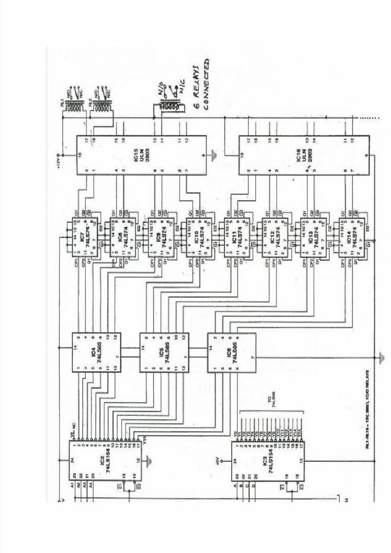
DC regulated supply. Each relay is rated 12V,200-ohm.The circuit for switching on/off 6 loads is shown in Fig. 2. For more than 6 loads, you can add more ICs
in a similar way as shown in this circuit. IC 74LSI54 is a 24-pin, 4-to-16 line decoder IC. This IC is
designed to accept four inputs and provide 16outputs. Input addresses Al through A4 to pins 20 through
23 of IC1 and IC2 (IC 74LSI54) each are given from the data lines of the computer parallel port.
In this circuit, only pins 2 through 9 of the parallel port are used, where data lines D0 through D3 form
the 4-bit data input and D4 through D7 are address-select or control lines for the circuit. Pins 18 through
25 are shorted to ground. Data lines D0 through D3 are the input addresses for IC2, and data linesD4
through D7 are the input addresses for IC1.
When Enable pins EI and E2 (active low) are high, all the outputs go high irrespective of the address
inputs (AI through A4). Enable pins EI and E2 of ICI are grounded and its output pins YO through YI5 are
connected to Enable pins of the respective decoder ICs.Initially all the data inputs (D0 through D7) are low. Thus, except Y0,all the outputs of ICI and IC2 are
high. The output Y0 of IC2 is not used, for the reason that when all the input data is low, none of the
outputs of IC 74LSI54 is used for switching the loads. Suppose, out of eight input data lines, D0 is high.
So, except Y1, all the outputs of IC2 will be high. YI is then inverted using IC4 (IC 74LS05). The output
of IC4 at pin 2 is given to pin 3 of IC7 (lC 74LS74). IC 74LS74 is a dual D-type flip-flop used for latching
the data.
With an active rising edge of the clock pulse (CP-1 or CP-2), the data input will be locked in IC7 through
IC14 until the next rising edge of the input clock pulse. The outputs of ICs 74LS74 are given to relay
driver ICs ULN2803 (lC-15 and IC-16), which, in turn, drive the relays. The relays are used to switch
on/off the appliances.
8/2/2019 Mini Project 2 Complete Data
http://slidepdf.com/reader/full/mini-project-2-complete-data 6/18

8/2/2019 Mini Project 2 Complete Data
http://slidepdf.com/reader/full/mini-project-2-complete-data 7/18
Fig 2. Circuit diagram of the project
SOFTWARE :
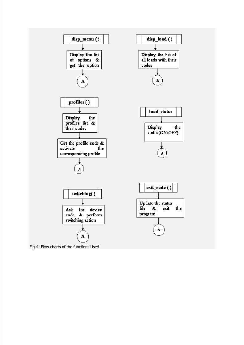
The program to control the appliances is written in C. it is compiled using Turbo C compiler. The flow
chart of the program is as follows
Fig-3: Flow chart for Implementation of Program
8/2/2019 Mini Project 2 Complete Data
http://slidepdf.com/reader/full/mini-project-2-complete-data 8/18

8/2/2019 Mini Project 2 Complete Data
http://slidepdf.com/reader/full/mini-project-2-complete-data 9/18
On running the program SRC_CODE.C the menu appears as shown below, asking
for the operation to be done.
The very first option shows the list of the loads that could be controlled using thissoftware along with their codes.

8/2/2019 Mini Project 2 Complete Data
http://slidepdf.com/reader/full/mini-project-2-complete-data 10/18
The outstanding part of this software is activating of required PROFILES at once sothat the burden of controlling of individual devices is eliminated.
The activation of night profile is as shown below. We can even set the user definedprofiles.
As a basic requirement the control over individual devices is also provided. If theuser by mistake tries to switch ON the device which is already ON, the softwaredetects it & the corresponding message is displayed.

8/2/2019 Mini Project 2 Complete Data
http://slidepdf.com/reader/full/mini-project-2-complete-data 11/18
The software also allows the user to know the current status of the loads.

8/2/2019 Mini Project 2 Complete Data
http://slidepdf.com/reader/full/mini-project-2-complete-data 12/18
SOURCE CODE: /* PROGRAM TO CONTROL MULTIPLE DEVICES USING PC‟S PARALLEL PORT */ #include<stdio.h>#include<conio.h>#include<stdlib.h>
#include<dos.h>#include<string.h>FILE *status;int ch;char *dev_list[]={“idle”,”TUBELIGHT”,”FAN”,”NIGHTLAMP”,”TELEVISION”,
”AIRCOOLER”,”REFRIGERATOR”,”DVD_PLAYER”,”end” }; int day[]={0,2,4,6,0,1,3,5,7,0};int night[]={0,1,2,3,5,6,7,0,4,0};int out[]={0,3,0,1,2,4,5,6,7,0};int reset[]={0,0,1,2,3,4,5,6,7,0};
int device[256];int port=0×378;void activate(int *ptr);void switch_load(int);main(){int disp_menu();void disp_load();void profiles();void switching();
void load_status();void exit_code();int welcome();int choice;int hour;status_file();for(;;){clrscr();hour=welcome();
choice=disp_menu();switch(choice){case 1: disp_load();printf(“nnn Press any key to continue….”); getch();break;

8/2/2019 Mini Project 2 Complete Data
http://slidepdf.com/reader/full/mini-project-2-complete-data 13/18
case 2: profiles();break;case 3: switching();break;case 4: load_status();
break;case 5: exit_code(hour);default: printf(“nn INVALID CHOICE”); printf(“nnnnn PRESS ANY KEY TO RETURN TO MAIN MENU…..”); getch();}}}status_file(){
int i=0;status=fopen(“status.txt”,”r”); if(status==NULL){puts(“Unable to open device status file”); exit(1);}while(1){ch=fgetc(status);
if(i>=256)break;elsedevice[i]=ch;i++;}fclose(status);return(0);}welcome()
{struct time t;struct date d;clrscr();printf(“nnttt $$$ POWER CONTROL USING PC $$$nnn”); gettime(&t);getdate(&d);

8/2/2019 Mini Project 2 Complete Data
http://slidepdf.com/reader/full/mini-project-2-complete-data 14/18
printf(“nn TIME: %2d:%2d”,t.ti_hour,t.ti_min); printf(“nn DATE: %2d/0%d/%2d”,d.da_day,d.da_mon,d.da_year); if(t.ti_hour>=0×5&&t.ti_hour<0xb)printf(“nn GOOD MORNING….n”); if(t.ti_hour>=0xb&&t.ti_hour<0×11)
printf(“nn GOOD AFTERNOON….”); if(t.ti_hour>=0×11&&t.ti_hour<0×16)printf(“nn GOOD EVENING….”); return(t.ti_hour);}int disp_menu(){int choice;printf(“n 1.LIST OF LOADS & THEIR CODES”); printf(“n 2.STANDARD PROFILES(DAY/NIGHT)”);
printf(“n 3.SWITCHING”); printf(“n 4.LOAD‟S STATUS”); printf(“n 5.EXITn”); printf(“tttt ENTER YOUR CHOICE:”); scanf(“%d”,&choice); return(choice);}void disp_load(){int i;
clrscr();printf(“n THE LIST OF LOADS WHICH CAN BE CONTROLLED ARE:nn”); for(i=1;strcmpi(&dev_list[i][0],”end”);i++) printf(“nt %2d.%s”,i,dev_list[i]); return;}void profiles(){char p;for(;;)
{clrscr();printf(“n STANDARD PROFILES:n”); printf(“nntt 1.DAY MODE”); printf(“ntt 2.NIGHT MODE”); printf(“ntt 3.OUT OF STATION”); printf(“ntt 4.RESET”);
8/2/2019 Mini Project 2 Complete Data
http://slidepdf.com/reader/full/mini-project-2-complete-data 15/18
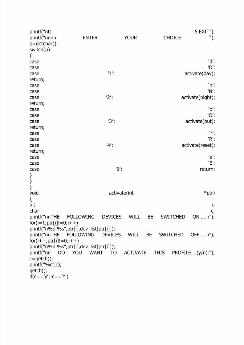
printf(“ntt 5.EXIT”); printf(“nnnn ENTER YOUR CHOICE: “); p=getchar();switch(p){
case „d‟: case „D‟: case ‟1′: activate(day);return;case „n‟: case „N‟: case ‟2′: activate(night);return;case „o‟: case „O‟:
case ‟3′: activate(out);return;case „r‟: case „R‟: case ‟4′: activate(reset);return;case „e‟: case „E‟: case ‟5′: return;}
}}void activate(int *ptr){int i;char c;printf(“nnTHE FOLLOWING DEVICES WILL BE SWITCHED ON…..n”); for(i=1;ptr[i]!=0;i++)printf(“n%d.%s”,ptr[i],dev_list[ptr[i]]); printf(“nnTHE FOLLOWING DEVICES WILL BE SWITCHED OFF…..n”);
for(i++;ptr[i]!=0;i++)printf(“n%d.%s”,ptr[i],dev_list[ptr[i]]); printf(“nn DO YOU WANT TO ACTIVATE THIS PROFILE….(y/n):”); c=getch();printf(“%c”,c); getch();if(c==‟y'||c==‟Y')
8/2/2019 Mini Project 2 Complete Data
http://slidepdf.com/reader/full/mini-project-2-complete-data 16/18
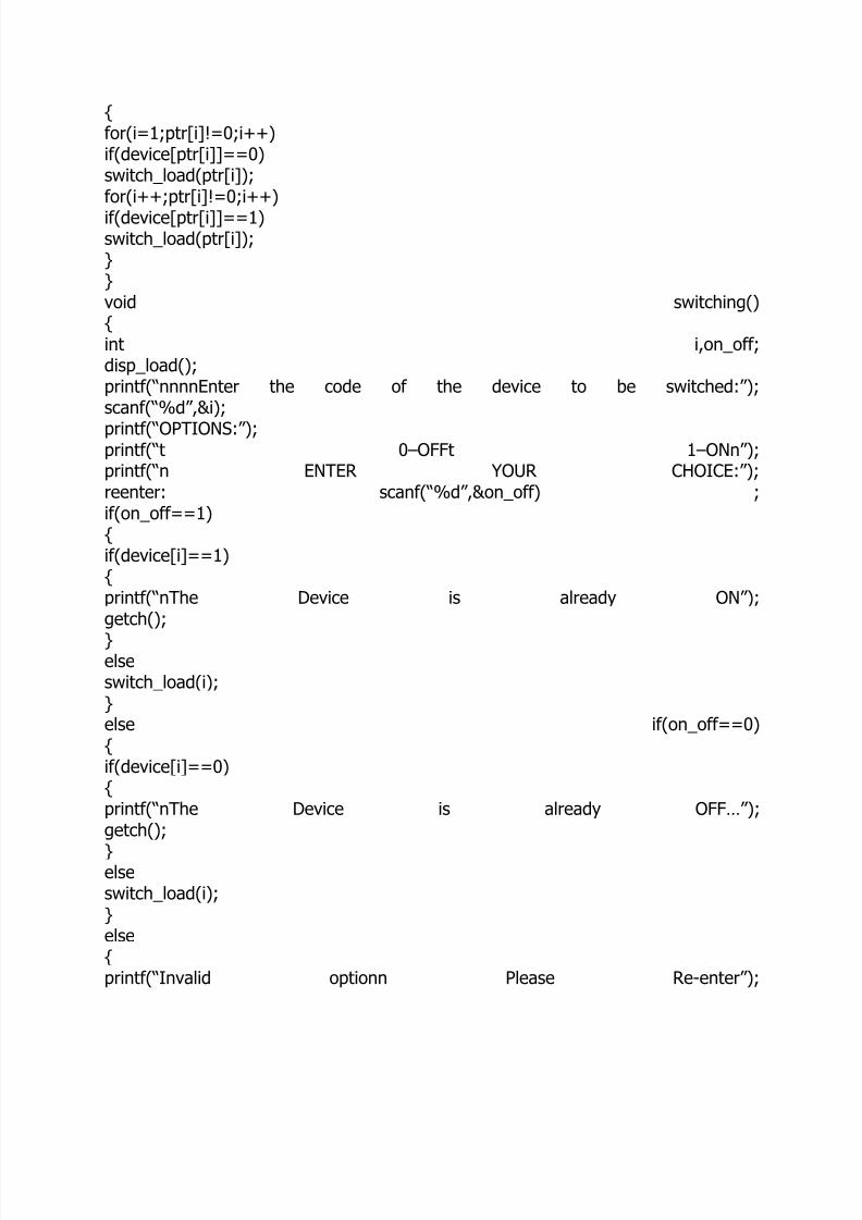
{for(i=1;ptr[i]!=0;i++)if(device[ptr[i]]==0)switch_load(ptr[i]);for(i++;ptr[i]!=0;i++)
if(device[ptr[i]]==1)switch_load(ptr[i]);}}void switching(){int i,on_off;disp_load();printf(“nnnnEnter the code of the device to be switched:”); scanf(“%d”,&i);
printf(“OPTIONS:”); printf(“t 0–OFFt 1 –ONn”); printf(“n ENTER YOUR CHOICE:”); reenter: scanf(“%d”,&on_off) ; if(on_off==1){if(device[i]==1){printf(“nThe Device is already ON”); getch();
}elseswitch_load(i);}else if(on_off==0){if(device[i]==0){printf(“nThe Device is already OFF…”); getch();
}elseswitch_load(i);}else{printf(“Invalid optionn Please Re-enter”);

8/2/2019 Mini Project 2 Complete Data
http://slidepdf.com/reader/full/mini-project-2-complete-data 17/18
goto reenter;}}void load_status(){
int i;clrscr();printf(“nn THE FOLLOWING DEVICES ARE ON:n”); for(i=1;strcmpi(&dev_list[i][0],”end”);i++) if(device[i]==1)printf(“n%d.%s”,i,dev_list[i]); printf(“nnTHE FOLLOWING DEVICES ARE OFF:n”); for(i=1;strcmpi(&dev_list[i][0],”end”);i++) if(device[i]==0)printf(“n%d.%s”,i,dev_list[i]);
printf(“nnnnPress any key to continue……”); getch();}void switch_load(int adrr){if(device[adrr]==0){device[adrr]=1;outportb(port,adrr);delay(50);
outportb(port,0×00);}else{evice[adrr]=0;outportb(port,adrr);delay(50);outportb(port,0×00);}}
void exit_code(int hour){clrscr();printf(“ttt THANK YOU FOR USING THIS SOFTWARE n”); if(hour>=0×13||hour<=0×4)printf(“nn GOOD NIGHT….n”); file_update();

8/2/2019 Mini Project 2 Complete Data
http://slidepdf.com/reader/full/mini-project-2-complete-data 18/18
printf(“nnnnnnn Press any key to EXIT……”); getch();exit(0);}file_update()
{int i=0;status=fopen(“status.txt”,”w+”); if(status==NULL){puts(“Unable to open device status file”); exit(1);}while(1){
ch=device[i];if(i>=256)break;elsefputc(ch,status);i++;}fclose(status);return 0;}
CONCLUSION: This project, can be effectively and conveniently utilized for the control of differentappliances. As this project could be extended to control about 255 devices, thiscould be used for computerization of an office, home, or a firm. Though it is quietcostlier, the circuit is simple and the working mechanism could be easily understood.
An added advantage of this project is that we are able to know the status of thedevice to be controlled. The program to control the appliances is written in Clanguage which is more user friendly and easy to understand than otherprogramming languages.Disadvantages / Improvements:-
If at all a new device has to be added to the hardware the software doesn‟t supportthis to achieve which the source code has to be changed manually.The status of all the devices that are switched are maintained in a database whichmay not coincide with actual status of the devices as we are not reading the statusdirectly from the HARDWARE.


