Embed Size (px)
Citation preview

1
MILSketch - Introduction 1. Introduction MILSketch endeavors to create a software solution to military “course-of-action” (COA) and other sketching activites. The U.S. and, at a higher level NATO, armed forces have an elaborate doctrine and methodology for symbology and graphics described in FM 101-5-1 Operational Terms and Graphics, and MIL-STD-2525B Common Warfighting Symbology. MIL-STD-2525B alone is 556 pages of complex symbols, diagrams, and sample sketches with instructions of how to create military graphics on paper, on a computer screen, or anywhere else where the symbols can be graphically communicated. Naturally, it would be desirable to have software package that can create attractive, professional looking diagrams that conform with the official specifications wherever possible. These diagrams are normally used for training, for planning, for after-action-reports, and in actual field exercises and real action. Most of the time these sketches are done by hand on a map or with a grease pencil on an acetate overlay over a map. Sometimes tools like PowerPoint, Photoshop, or similar paint programs are used to create the diagrams. There are even special font typefaces available that contain the various symbols as individual characters. The chief complaint regarding software specifically designed to create the symbology is that it is difficult to learn and use. Therefore, in creating “MILSketch”, every effort was made to keep it as simple and robust as possible. Several very basic steps are involved in the process of creating a sketch using the program:
1. A background image is chosen which can be any bmp, jpg, or gif file. Normally, this would be assumed to be a map, such as a topographical map, of an area of interest. However, it could be an image of anything.
2. The user can choose to resize the image file as needed before continuing on with the creation of the sketch.
3. A border of any color can be added of any dimension on any side. This may be useful for textual annotations later or for aesthetic purposes.
4. A name for the sketch is selected, which will initially be used as the file name for early saves.
5. At this point the sketch window is created and the image can be viewed 1:1 (one pixel to one pixel screen resolution) or at any zoom level. It is useful to draw at 1:1 because what you see is what you will really get. However, zoom views can be useful for map overview scans.

2
6. The user then can perform several basic image quality functions as needed until the sketch is complete: brightness adjustment, contrast adjustment, gamma adjustment, and rotation.
7. The user can add the 3 basic glyph types in any succession: a. Unit symbols with their attached textual annotations. b. Normal and specialty lines. c. Text annotations.
8. When the user has completed adding any number of glyphs, the sketch can be saved or copied as a bmp or jpg file and distributed.
9. Additionally, up to ten levels of “Undo” and “Redo” are supported at each stage of sketch change.
2. Usage Below is a screenshot of “MILSketch”. The window on the upper left is the unit symbol selector window. Over 2,500 symbols are included with the program as 3 color gif files. White is the transparent background color for each symbol, RGB(200,200,20) yellow is a fill color that can later be changed to any color, and black is the symbol line color which can also be changed to any color in the sketch by the user.
The user can select from any of the symbols which are displayed in the symbol selection window in designing their current symbol. The symbols are divided, following common practice, into the following sub-directories:

3
Each directory has several hundred of the official symbols for each unit or equipment type. The user then designs the specifics of their symbol using the “Unit Symbol Designer” window (shown below the symbol selector window). Then, the symbol can be generated and “pasted” into a current sketch. The program allows multiple various sketches to be open at one time. Also shown on the screenshot below are the main sketch window, the line selector window, and the “Line Designer” window. Like military unit symbols, line image types have special meanings. Over 60 individual line types were able to be discerned from the documents listed above. Below are the cover pages for the relevant references for U.S. and NATO military symbols and graphics.
4
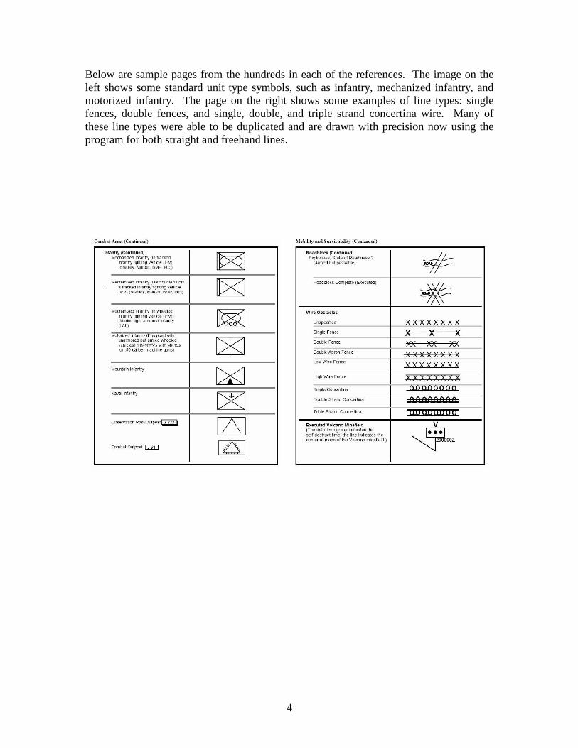
Below are sample pages from the hundreds in each of the references. The image on the left shows some standard unit type symbols, such as infantry, mechanized infantry, and motorized infantry. The page on the right shows some examples of line types: single fences, double fences, and single, double, and triple strand concertina wire. Many of these line types were able to be duplicated and are drawn with precision now using the program for both straight and freehand lines.

5
Below is the “New Sketch Creation” window. Here the user can choose their background image, resize it as desired, add a border of any color and dimension, and name the sketch before proceeded on with actual sketch drawing.
Upon sketch creation, the background image is displayed in a new sketch window. A sample image is shown below using a Google Maps roadmap from Germany as the background. At the top of the window are buttons for locking the zoom of the sketch to 1:1, or allowing any zoom level, “Undo”, “Redo”, “Merge Current Selection”, “Delete Current Selection”, “Straight Line”, and “Freehand Line”.

6
Below is an example of a simple sketch that was completed in about ten minutes. Normally, friendly troops and objects are displayed in blue, and enemy forces, dispositions, and activities are displayed in red. You can see a complete “BLUFOR” symbol in the lower left, and two “OPFOR” type symbols in the upper right. The BLUFOR symbol, as an example, indicates an ad hoc battalion Task Force task force sized unit based around the 3-54 Mechanized Infantry battalion, of the 2nd Brigade of the 2nd Infantry Division. An unofficial optional text annotation below indicates command under a “LTC Bird”. A “FLOT” (forward line of troops) special line indicates the location of the FLOT. OPFOR symbols indicat tank companies “A” and “B” of the 333rd Battalion / 1st Regiment, 7th Motorized Rifle Division. Text annotation below indicates T-90 type tanks. Arrow lines indicated planned or potential movement. OPFOR double strand concertina wire is shown (2 belts), and 2 belts of Scatterable Minefields (Unspecified mines) with Self-Destruct Date-Time Groups.

7
Below is a close-up of the unit symbol selection window. The user chooses the subdirectory on the left directory window, and the thumbnails from this directory are then displayed in the area to the right. The user can scroll down and select any of the symbols and symbol modifier images. Symbol modifier images are superimposed over the general symbol shape and size to display additional information, such as the size of the unit, task organization, and additional capabilities. The yellow will be the fill color area for the symbol, white is transparent, and black is the regular line color.
When a symbol is chosen by clicking on it, it is loaded into the picture area that was selected in the unit symbol designer window. This window has picture areas for the unit’s main symbol, an optional back image, and two symbol modifier images.

8
The window below has an example of the creation of the BLUFOR unit previously mentioned. The regular symbol image for mechanized infantry was chosen (“Symbol” picture). The user then chose blue for the line color and cyan for the fill color— the symbol was then re-colored accordingly. No back image was chosen. Two symbol modifier images were chosen: two vertical lines indicate a battalion sized unit, and the top bracket indicates a temporary or “Task Force” organized unit. The color blue was again chosen for these images. Left text, right text, and bottom text can then be added and colors chosen for each of these. Additionally, each object mentioned so far has scrollbars to position it in the overall created image (shown to the right) and X,Y coordinates, and to scale it in size relative to the other objects. The created symbol is then “built” and displayed in the picture box to the right and can be rotated as needed for later pasting into a sketch window. Further, a transparency value (0 to 100) can be selected to make the symbol partially transparent over the background map.
Below is shown the RGB color picker window. The user merely slides the scrollbars to select color values 0 – 255 for red, green, and blue. The color created is displayed above any original color.

9
Below is the text annotation designer window. Single line or multiple line text annotations can be sized, moved, and rotated before pasting into a sketch. Color and transparency can also be chosen.
Below is the line designer window. Similar to the unit symbol creator window, a stock image is chosen with can then be colored and sized as needed. Unlike the pasting operation with unit symbols and with text annotations, however, the user must actually draw a line over the sketch window to create a line. Both straight and freehand lines of various shapes and sizes can be created relatively easily.
10
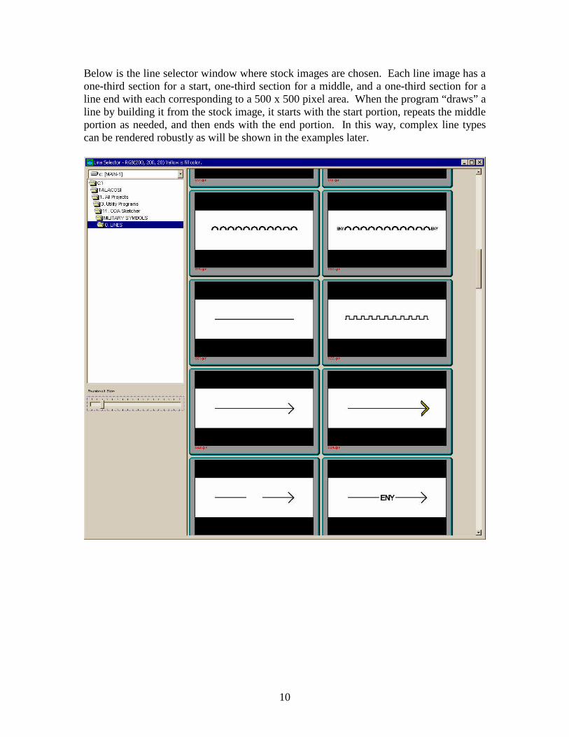
Below is the line selector window where stock images are chosen. Each line image has a one-third section for a start, one-third section for a middle, and a one-third section for a line end with each corresponding to a 500 x 500 pixel area. When the program “draws” a line by building it from the stock image, it starts with the start portion, repeats the middle portion as needed, and then ends with the end portion. In this way, complex line types can be rendered robustly as will be shown in the examples later.

11
Below is shown the creation of the OPFOR unit symbols.
Here were some of the steps to creating the sample sketch. The BLUFOR unit was “selected” into the sketch window. It has a blinking highlight and can be moved and relocated as needed by clicking on its visible portion with the mouse and dragging. The, the “Merge Selection” button at the top of the window is pressed to permanently merge it with the background image and then proceed to adding other symbols. If needed, “Undo” can be pressed to move back to a previous state.

12
Next, a straight arrow type line was added by clicking and dragging over the sketch after the “Straight Line” button had been selected. The line type had been previous chosen and colored in the line designer window. The selection is highlighted (as shown) with a blinking rectangle until it is merged with the background image or deleted. Also, it can be moved by dragging it with the mouse.
Then, a freehand line was added of the same style.

13
By batching unit symbol creation, units with similar symbols can be created from the same template in the fly. All that was needed for the change in the two OPFOR symbols was the Company letter; “A” to “B”.
Arrow lines were chosen and colored to indicate movement.

14
The BLUFOR “forward line of troops” or “FLOT” line type was chosen and drawn. Note the line ends’ text is shown only on the ends and not repeated inside the length of the line.
Here is the line design for double strand concertina wire for OPFOR (Red) forces.

15
The line types for concertina wire, and minefields (Type: Scatterable Minefield [Unspecified mines] with Self-Destruct Date-Time Group), were added using 50% transparency to complete the sketch.
The basic image processing functions within the program (more will be added later, such as resizing the image and increasing sharpness). Brightness:
Contrast:

16
Gamma:
Rotation:
After an image is saved as a BMP file, it can be converted to JPG file format by MILSketch:
2. Program Setup Setup is a standard Windows installation and the setup file is 26MB in size. Much if this size is due to the 2,470 symbol image bitmaps included and complete reference PDF file copies of FM 101-5-1 Operational Terms and Graphics, and MIL-STD-2525B Common Warfighting Symbology. The setup file can be downloaded from the following link:
http://www.historicalsoftware.com/HSC/Upload/MILSketch_Setup.exe

17
Several sample background images are included that can be used as starting points for sketches. Probably the greatest strength of the program is that it is simple to use, followed by the fact that you really can create attractive, professional looking images using official symbology.