Embed Size (px)
Citation preview

-.L’:L :? ““.”’. .
—- ———-. —___ .- _ .
MI1-STD-7046 OCTOBER1959
SUPERSEDINGMIL-E-7894A(ASG)17 MAY 1955
MILITARY STANDARD
ELECTRICPOWER, AIRCRA~,
CHARACTERISTICSAND UTILIZATION OF
,,~.
,,//”____ ____ ___ ——-
Downloaded from http://www.everyspec.com

\. .._. _.____. _— ——–—
MI.-STD-7O46 Octobar 1959
DEPARTMENT OF DEFENSE
ARMED FORCSS SUPPLY SUPPORT CENTERWASHINGTON25, D. C.
ELRCTRIC POWER, AIRCRAFT, CHARACTERISTICSAND UTILIZATION OF
MIL-STD-704 6 October 1959
1. This standard has been approved by the Department of Defenseand is msndatmy for use by the Army, the Navy, and the Air Force,effective 6 October 1959.
2. In accordance with established procedure, the TransportationCaps, Bureau of Aeronautics, end Air Force have been designated, re-spectively, as Army-Navy-Air Force custodians of this standard.
3. Recommended corrections, additions, or deletions should beaddressed to the Standardization Division, Armed Fomes Supply SupportCenter, Washington 25, D. C.
ii
,_ .2 ‘““ .... . . . . . . . . .
__. —— ——
Downloaded from http://www.everyspec.com

1.1.112
2..%3.13.23.33.43.53.63.’73.83.93.103.113.123.133.143.153.163.173.18
4.4.14.1.14.1.24.2
5.6.16.1.15.1.25.1.3
-,._ ______ --
GENERAL . . . . . . . . . . . . . . . . . . . . . . . . . . . . . . . . . . . . . . . . . . .scope . . . . . . . . . . . . . . . . . . . . . . . . . . . . . . . . . . . . . . . . . . . . . . .
. . . . . . . . . . . . . . . . . . . . . . . . . . . . . . . . . . . . . . . . . . . . .
APPLICABLE DOCUMENTS . . . . . . . . . . . . . . . . . . . . . . . . . . .DEFINITIONS . . . . . . . . . . . . . . . . . . . . . . . . . . . . . . . . . . . . . . .
Average value . . . . . . . . . . . . . . . . . . . . . . . . . . . . . . . . . . . . . . . .Ground . . . . . . . . . . . . . . . . . . . . . . . . . . . . . . . . . . . . . . . . . . . . . .Trandent . . . . . . . . . . . . . . . . . . . . . . . . . . . . . . . . . . . . . . . . . . . .Total harmonic content . . . . . . . . . . . . . . . . . . . . . . . . . . . . . . .. . .Frequency modrdation . . . . . . . . . . . . . . . . . . . . . . . . . . . . . . . . .Frequency modulation rate . . . . . . . . . . . . . . . . . . . . . . . . . . . . . .Frequency drift . . . . . . . . . . . . . . . . . . . . . . . . . . . . . . . . . . . . . . .Frequency drift rate . . . . . . . . . . . . . . . . . . . . . . . . . . . . . . . . . . .A-c VO]tll& . . . . . . . . . . . . . . . . . . . . . . . . . . . . . . . . . . . . . . . . . .Voltage modulation . . . . . . . . . . . . . . . . . . . . . . . . . . . . . . . . . . . .Voltage mcdulatkmf requeneyc harackietk . . . . . . . . . . . . . .Ripple . . . . . . . . . . . . . . . . . . . . . . . . . . . . . . . . . . . . . . . . . . . . . . .Unssfewndition . . . . . . . . . . . . . . . . . . . . . . . . . . . . . . . . . . . . . .Aireraft operation peril@ . . . . . . . . . . . . . . . . . . . . . . . . . . . . . . .Utilization equipment . . . . . . . . . . . . . . . . . . . . . . . . . . . . . . . . . .Category `'A'' utiliition equipment . . . . . . . . . . . . . . . . . . . . . .Category `'B'' utiliition equipment . . . . . . . . . . . . . . . . . . . . . .Category ``C''utilisetion equipment . . . . . . . . . . . . . . . . . . . . . .
GENERAL REQUIREMENTS . . . . . . . . . . . . . . . . . . . . . . . . . .Power ayateJm9 . . . . . . . . . . . . . . . . . . . . . . . . . . . . . . . . . . . . . . . .
A-cpawer . . . . . . . . . . . . . . . . . . . . . . . . . . . . . . . . . . . . . . . . .D-c power . . . . . . . . . . . . . . . . . . . . . . . . . . . . . . . . . . . . . . . .
Utiliition equipment . . . . . . . . . . . . . . . . . . . . . . . . . . . . . . . . . .
DETAIL REQUIREMENTS . . . . . . . . . . . . . . . . . . . . . . . . . . . .A-epower syatemcharackiatica ..;.. . . . . . . . . . . . . . . . . . . .
.
MIL-STD-7046 Octobw 1959
Page
6.1.3.15.1.3.25.1.3.35.1.3.45.1.3.55.1.3.65.1.3.6.15.1.3.6.25.1.4
L-ine-@n&tml . . . . . . . . . . . . . . . . . . . . . . . . . . . . . . . . . . . . .LindcAine . . . . . . . . . . . . . . . . . . . . . . . . . . . . . . . . . . . . . . . .steady-state voltage . . . . . . .. . . . . . . . . . . . . . . . . . . . . . . . . .Single pke . . . . . . . . . . . . . . . . . . . . . . . . . . . . . . . . . . . . . . .Three phase . . . . . . . . . . . . . . . . . . . . . . . . . . . . . . . . . . . . . . .Phaaedisplscementa . . . . . . . . . . . . . . . . . . . . . . . . . . . . . . . .Unhalanee . . . . . . . . . . . . . . . . . . . . . . . . . . . . . . . . . . . . . . . .Wave form . . . . . . . . . . . . . . . . . . . . . . . . . . . . . . . . . . . . . . . .Modtdation . . . . . . . . . . . . . . . . . . . . . . . . . . . . . . . . . . . . . . . .Amplitude . . . . . . . . . . . . . . . . . . . . . . . . . . . . . . . . . . . . . . . .Frequency characteristics . . . . . . . . . . . . . . . . . . . . . . . . . . . .Transient voltage . . . . . . . . . . . . . . . . . . . . . . . . . . . . . . . . . . .
. . .m
i11
111111111111
:222222
22222
222,23333333333
.
Downloaded from http://www.everyspec.com

M1l-!m-7046 Octobor 1959
5.1.4.15.1.4.25.1.56.1.5.15.1.5.25.1.5.35.1.66.1.6.15.1.6.25.1.7
CONTENTS (Gmtinned)
Normal ektric-ayatem opemtion .. . . . . . . . . . . . . . . . . . . . . .Abnormal electri*syatem operation . . . . . . . . . . . . . . . . . . . .Stdy-irtat efrequency . . . . . . . . . . . . . . . . . . . . . . . . . .. . . . .Drift . . . . . . . . . . . . . . . . . . . . . . . . . . . . . . . . . . . . . . . . . . . . .Modulation ampfitude . . . . . . . . . . . . . . . . . . . . . . . . . . . . . . .Mcdulationrate . . . . . . . . . . . . . . . . . . . . . . . . . . . . . . . . . . . .Transient frequency . . . . . . . . . . . . . . . . . . . . . . . . . . . . . . . .Normslelechiesyatem operation . . . . . . . . . . . . . . . . . . . . . .AbnormsIe ktri*systernoper ation . . . . . . . . . . . . . . . . . . .PheseseWencY . . . . . . . . . . . . . . . . . . . . . . ..! . . . . . . . . . . .
5.2 D-cpower syti-ehamcteristice . . . . . . . . . . . . . . . . . . . . . . . .5.2.1 St=dy-state voltage . . . . . . . . . . . . . . . . . . . . . . . . . . . . . . . .5.2.2 Ripple . . . . . . . . . . . . . . . . . . . . . . . . . . . . . . . . . . . . . . . . . . . .5.2.2.1 Frcqoenc.v chsracteristica . . . . . . . . . . . . . . . . . . . . . . . . . . . ..5.2.3 Tnmsientv oltage. . . . . . . . . . . . . . . . . . . . . . . . . . . . . . . . . . .5.2.3.1 Normslekc.trksystemoper scion.... . . . . . . . . . . . . . . . . . .5.2.3,2 Abnormsl ekctric-systemop eration . . . . . . . . . . . . . . . . . . .
6. UTILIZATION OF AIRCRAFT ELECTRIC POWER .. . . . .6.16.26.2.16,36.46.56.66.76.86.3.16.96.9.16.9.26.9.36.9.46.9.56.106.116.126.136.13.1
Power types . . . . . . . . . . . . . . . . . . . . . . . . . . . . . . . . . . . . . . . . . .Conversion . . . . . . ... . . . . . . . . . . . . . . . . . . . . . . . . . . . . . . . . . . .
A-cto26voltadc.. . . . . . . . . . . . . . . . . . . . . . . . . . . . . . . . .Normslelectric-system operation . . . . . . . . . . . . . . . . . . . . . . . . .Abnormal electric-system opaation . . . . . . . . . . . . . . . . . . . . . .Other electric-system operation . . . . . . . . . . . . . . . . . . . . . . . . . .Voltage tmnsienta . . . . . . . . . . . . . . . . . . . . . . . . . . . . . . . . . . . . .warmup . . . . . . . . . . . . . . . . . . . . . . . . . . . . . . . . . . . . . . . . . . . . .Influence onekrtricsyatem........ . . . . . . . . . . . .. . . . . . . . .
Self-modulation . . . . . . . . . . . . . . . . . . . . . . . . . . . . . . . . . . . .A-c Power . . . . . . . . . . . . . . . . . . . . . . . . . . . . . . . . . . . . . . . . . . .
Tfmephase.. . . . . . . . . . . . . . . . . . . . . . . . . . . . . . . . . . . . . .Single phsse . . . . . . . . . . . . . . . . . . . . . . . . . . . . . . . . . . . . . . .Phaw balance . . . . . . . . . . . . . . . . . . . . . . . . . . . . . . . . . . . . . .Power factor . . . . . . . . . . . . . . . . . . . . . . . . . . . . . . . . . . . . . .Phase faihwe . . . . . . . . . . . . . . . . . . . . . . . . . . . . . . . . . . . . . .
Power failure . . . . . . . . . . . . . . . . . . . . . . . . . . . . . . . . . . . . . . . . ..Yandby power . . . . . . . . . . . . . . . . . . . . . . . . . . . . . . . . . . . . . . . .Power tolerance . . . . . . . . . . . . . . . . . . . . . . . . . . . . . . . . . . . . . . .Power requirements data (Requircxl for NaVY equipment only)
SsmplefOrm . . . . . . . . . . . . . . . . . . . . . . . . . . . . . . . . . . . . . . .
7. NOTES . . . . . . . . . . . . . . . . . . . . . . . . . . . . . . . . . . . . . . . . . . . . . . .7.1 h’ormal electric-system operation . . . . . . . . . . . . . . . . . . . . . . . .7.2 Abnormal ekctric-systemop eration . . . . . . . . . . . . . . . . . . . . . .7.3 Emergency electric-system op=stion . . . . . . . . . . . . . . . . . . . . .7.4 Reference voltage . . . . . . . . . . . . . . . . . . . . . . . . . . . . . . . . . . . . . .7.?5 Referent.e frequency . . . . . . . . . . . . . . . . . . . . . . . . . . . . . . . . . . .7.6 Conl-ersion of a transient to its evaluated step function loci. . .
iv
_,. .,_— .“’__. —...
Pags37777777773888838
3833
111111111111111212121212121212121212
15151717171717
:-.—.-—— .._ __ _
Downloaded from http://www.everyspec.com

7.6.17.77.87.97.9.17.9.27.9.97.9.47.9.67.9.67.9.77.9.8
1.2.3.4.5. .
&7’.8.9.
10.
11.
T.IL
——.—.,-----
MIL-STD-7046 Ocbbar 1959
CONTENTS (Continued)Page
Fault tramienta. . . . . . . . . . . . . . . . . . . . . . . . . . . . . . . . . . . . 17L.inedrop eompmeation. . . . . . . . . . . . . . . . . . . . . . . . . . . . . . . . 19Equipment detiilspwification . . . . . . . . . . . . . . . . . . . . . . . . . . . ’19AssmnPtfomc . . . . . . . . . . . . . . . . . . . . . . . . . . . . . . . . . . . . . . . . . 19
SrnSllest primary ekctricsyatem.... . . . . . . . . . . . . . . . . . . 19EIectilc-system balance . . . . . . . . . . . . . . . . . . . . . . . . . . . . . 19Generatiig+ystem chsracteristica . . . . . . . . . . . . . . . . . . . . . 20Electric-syatem chsracteristica ...,... . . . . . . . . . . . . . . . . . 20Nortnal loading . . . . . . . . . . . . . . . . . . . . . . . . . . . . . . . . . . . . 20Initisl warmup . . . . . . . . . . . . . . . . . . . . . . . . . . . . . . . . . . . . . 20System power factor . . . . . . . . . . . . . . . . . . . . . . . . . . . . . . . . 20Power-aystem rating . . . . . . . . . . . . . . . . . . . . . . . . . . . . . . . . 20
FIGURES
Frequency characteristics of a-c voltage modulation envelope . .Transient a-c voltage step function loci limits . . . . . . . . . . . . . .Transient frequency tilts . . . . . . . . . . . . . . . . . . . . . . . . . . . . . .D]agram of phase seq~eney and line designations . . . . . . . . . . .Frequency characteristics of ripple in 28-volt d-c electric
systems . . . . . . . . . . . . . . . . . . . . . . . . . . . . . . . . . . . . . . . . . . . .Transient d-c voltage step function loci limits . . . . . . . . . . . . . .Unbalance Iti]ta for 3-phsse utilisation equipment . . . . . . . . . .Lagging power factor ltilts for utilisation equipment . . . . . . . .Sample form for submittal of power requirements data . . . . . .Sample conversion of an overvoltage transient to its evaluated
step functio nloe i . . . . . . . . . . . . . . . . . . . . . . . . . . . . . . . . . . .Standard MIL-STD-704 power utilization checfdkt . . . . . . . . .
4567
910131416
1819
TABLES
Steady-state a-evoltsge ltilts . . . . . . . . . . . . . . . . . . . . . . . . . . . 3Steady+tatcd -cvoltagel emits.... . . . . . . . . . . . . . . . . . . . . . . . S
.._._,,, . ..-
—..
v
.
._— —.~..-—. —— -- -.——.
Downloaded from http://www.everyspec.com
.
‘--------- ._ -.. .._____ _____ ______ __
MIL-STO-7046 October 1959
MIUTARY STANDARD
ELECTRIC POWER, AIRCRAFT,
CHARACTERISTICS AND UTILIZATION OF
1. (; ENERAI,
1,1 Scope. ‘fhis standard delineates thecharacteristics of electric power to be supplied to sirborne equipment at the equipmentterminals and the requirements for the utili-zation of such electric power by the airlmmeequipment.
1.2 Purpose. The purpose of this standardis to foster compatibility between aircraftelectric systems and airborrre utilizationequipment to the extent of confining the eir-cmft electric ~wer characteristics withindefinitive limits and restricting the require-ments imposed on the electric pewer by theairbnrne utilisation equipment.
2. APPLICABJ,E DOCUMENTS
2.1 Not appliesbie.
3. DEFINITIONS
Xl Average vrdue. The average valne ofphase quantities is the arithmetical sum ofthe phase values divided by the number ofphases.
3.2 Ground. The primary aircraft structureis the referenced ground for the negative ofthe dc and the neutral of the sc in the powergeneration and pnwer utilization systems.
3.3 Transients. A transient is the charrg-ing condition of a characteristic which geesbeyond the steady-state limits and returnsto the steady-state limits within a specifiedtime period.
3.4 Total harmonic content. The total har-monic content of a complex wave is the totalrrns voltage remaining when the fundamentalcomponent is removed.
3.5 Frequency modulation. Frequency mod-ulation is the cyclic or random dynruntc vari-ation, or bnth, of instantaneous frequencyabeut a mean frequency during steady-stateelectric-system operation. The frequencymodulation is normally within” narrow fre-quency Iirnita and eccnra as a result of speedvariations in a generator rotor owing to thedynamic operation of the rotor coupling anddrive speed regulation.
3.6 Frequency modulation rate. The fre-quency mmhdation rate is ‘the rate of changeof frequency owing to frequency modulationwhen plotted against Ulme.
3.7 Frequency drift. Frequency drift is tbeextremely slow and random variation in fre-quency within the steady-state limits occnr-ring as a result of environmental effects andwear on the electric power-drive system.
3.8 Frequency drift rate. The frequencydrift rate is the rate of change of frequencyowing to frequency drift when plottedagainst time.
3.9 A-c voltage. The a-c voltage valuesstated herein shall be for any phase of thosesupplied utilization equipment, a phase beingconsidered a line to neutral. All a-c voltagevalues are mot mean square (rrns) values.
3.10 Voltage modulation. Voltage morfula-tion is the cyclic variation or random rlY-namic Variations, or both, about an averageof the a-c peak voltage dining steady-stateelectric-eystem operation such es caused byvoltage regulation and speed variations. Themodulation envelope is formed by a continu-ous crmve connecting each sine wave peak tothe successive sine wave peak.
3.11 Voltage mndulaticur frequency char-acteristics. The frequency charactel”istic Of
1..
—.
—
—... —-- ,— -—- —--. —.-- .--.-—
Downloaded from http://www.everyspec.com

-.
MIL-STD-7046 Octobor 19S9
voltage modulation is defined as the comprm-ent frequencies which make up the modula-tion envelope wave form.
:1.12 Ripple. Ripple is the a-c variation ofvoltage about a fixed d-c voltage duringsteady-state d-c electric-system operation.
:1.13 Unsafe condition. An unsafe conditionis any condition within aircraft that jeopar-dizes the safety of the aircraft and the per-sonnel aboard.
3.14 Aircraft operational period. The oper-ational period of an aircraft is defined as thetime interval between the start of prepara-tion for flight and the post flight enginestiutdown with consequent deactivation ofttie aircraft electric system.
j 3.15 Utilization equipment. Utilizationequipment will be considered aa comprisingeither an individual unit, set, or a completesystem to which the electrical power is ap-plierl or disconnected, or both, as a whole.
3.16 Category “A” utilisation equipment:Category “A” equipment are those utilisa-tion equipments whose installation in aircraftwill be controlled so that line drops will belimited to 2-volts a-c line drop or $+volt dc.or botb. The line drup is the voltage differ-ence between the point of voltage regulationand the power input terminals of the equip-ment. Use of this category should be held toa minimum. and its use will be subject toapproval by the procuring activity.
3.17 category “B” utilimtion equipment.Category “B” equipment are thoee utilizationequipments destined for aircraft for whichthe line rtrups will be less than 4 volts sc or1 volt dc, or both. When a detd equipmentspecification does not desigaate a category,the equipment will be considered a category“B” equipment.
3.18 Category “C” utilization equipment.Category “C” equipment are those equip-ments which are intermittently operated.
~j -:—
.
During opcratimr, voltage limits include al-lowance for 8 volts a-c line drop or 2 voltsd-c line drop, or both.
4. GENERAL REQUIREMENTS
4.1 Power systems. Characteristics of air-craft puwer at the input terminals of utili-zation equipment shall be within the limitsstated in section 5 under the conditions ofpower utilization prescribed bisection 6.
4.1.1 A-cpowcr. Thea.cpower system shallhe a ,3-phase, 4-wire “Y” system, having anominal voltage of 115/200 and a nominalfrequency of 400 cps. The neutral point of thesource of power is connected to ground (see3.2), and the ground is considered the fourthconductor.
4.1.2 D-cpocuer. Thed-cpower systam shallbe a 2-wire, grounded system having a nomi-nrd voltage of 28 volts. The negative of thepower source isconnected to ground and theground is considered the second wire.
4.2 Utilization equipment. Utilization equip-ment shall maintain specified performance,using the puwer with characteristics whichare listed in section 5. When nse of poweris required having other characteristics ornarrower tolerances than specified herein, theconversion to other characteristics or closertolerances shall be accomplished as a part oftbe utilization equipment. Utilization equipment desigaed for a specific aircraft applica-tion may deviate from these requirementsonly upon approval of the procuring activity.
5. DETAII. REQUIREMENTS
5.1 A-cpawer eystem characteristics.
5.1.1 Liw-to-nsutd. Characteristics of line-~rreutral puwer shall be within the ltiltsspecified herein.
5.1.2 Line-to-lim. Characteristics of line-to-line power shall be as a result of line-to-neu-tral charecteristicsb eingasspscified,
Downloaded from http://www.everyspec.com

..—
..-.. —..- . . . . .
Madeof.Oemtl.” 1-----------
MIL-STO-70460ctober 1959
TABLMI. Steady-state a-c voltage Iimita
::Z=T-AZ;ZEZN.arm.l E—r Normal Em-r-w
——
Cateaory “A” 10%6h 119.5 107to 1ss 110.5to 117.5 10s t.a120——
Category“B” 107.5to 119.5 105to 122 108.5to 117.5 10s to 120
Categwy‘rC” I lo3.5t0119.6I Ioltolzz I m4.,tol,7.5 I lo2to 120
5.1.3 Steud@de voltage. The eteady-statephase voltage shall be within the limits oftable I. These limits are applicable during330- to 420-cPs operation. Mcdee of elestilc-syatem operation shown in table I and sub-sequent are explained in sdion 7. Utilisationequipment categories shown in table I andsubsequent are defined in aestion 3.
5.1.3.1 Single phuse. The steady-state vOlt-age for a single phase shall be within thelindte of table I.
5.1.3.2 Three phase. The steady-state volt-age average for the three phases shall bswithin the limits of table I.
5.1.3.3 Phase dieplucementu. The dBplece-ment betwaen adjacent phaam ehafl hs withinthe ltiIt9 of 120” * 1.5”.
5.1.3.4 Unbakwcce. Maxiimn spread inphase voltages shall be less than 3 volts ktween the phase with the highest voltage andthe phase with the lowest voltage for all afr-craft operations.
5.1.3.5 Wme fem. The voltage wave formshall bc within the following bits:
(a) Crest factor: 1.41 * 0.1.
(b) Total harmonic content: 4 persentof the fundamental (ma) withlinear loads, or 5 percent of thefundamental (rms) with non-linear loads, when measured wttha distortion meter se distortion ofthe fundamental frequency.
,. .—.
(c) Individual harmonic content: 3 per-cent of the fundamental (rma)with linear IOad9, or 4 perceut ofthe fundamental (me) with non-Itnear loads, when measured witha harmonic analyzer.
5.1.3.6 Moddutien.
5.1.3.6.1 AmpMu&. The modulation of volt-age (w= 3.1O) shall not exceed an amplitudeof 3.5 volts when measured 32 the peak-to-velley dflerence between the minbmnn voltagermched and the maximum voltage rearhed onthe modulation envelope over a pariod of atleast 1 eewnd. A sketch of voltage modulationis ehown in figure 1.
5.1.3.6.2 FmqNensu .+uwuchietics. The fr+quency components of the veltaga modulationenvelope wave form (see 3.11) shelf be wit.ldmthe Iinits specified in figure L
5.1.4 ‘l%zmid voltage. Voltage tram9kn@wfien converted to their evaluated *P func-tion losi (se@ 7.6), aid bs @hbr the limitsof figure 2 for all operation of the airsraftelestric system. The mmt severe phaee tran-sient shall ba uaad in detemnbdng mnform-anm to figure 2.
5.1.4.1 Normal electric-swtenc opemtiun.The evaluated step funstion Ioei of the a-svoltage transients for all normal elestric-sya-tem operations shall be witldm the limits 2and 3 of figure 2.
3
..— __,7
...—- ———-.—-.—-.—- _—
Downloaded from http://www.everyspec.com

MIL
-STD
-7046
Odder
1959
I—
II
-—-i––t–t–l–
————
——
00
0Ou
*m
Lx
-.
c
(‘“dA
)A
311VA01)lV3dNOllVlilaOW
4
,.—----”
——..
,=
--—
)!3_——
Downloaded from http://www.everyspec.com

—
1,..
..-.—
_..
——
—-—
MIL
-STD
-7046
Odder
1959
S11OA
Swm
b
>.___
.—
-.—
—_____
___
Downloaded from http://www.everyspec.com

I
—-~
Yf ——...._g●
->:.:.
.—
‘-—-—
.--—
-—‘.
MIL
-m704
..——
.._._—
6W
Obw
1959
\
r--—
——
\,
I
\—
\l
m
..—
—
go
go:
N*
6..
-—
..-
——.————.————/—————..
..-
..
...
._—
._
Downloaded from http://www.everyspec.com

. .
GENERATOR
MIL-STD-7046 &tek1959
UTILIZATIONEQUIPMENT
IA
B
c
NEU’TRALx
& A I
“A
PHASE SEQUENCE; A*B .C
N
c B
F1cuea4.Diawamofphuw sequenceand line den”enaiiona
5.1.4.2 Abrwmmd eteetric-wtem operition.‘l’be evaluated step function loci of the a-cvoltage transients which result frmn abnormalelectAc-system operation shall be less thanthe limks 1 and 4 of figure 2.
3.1.5 Steady-state freqaencp. The a-c powerSW- frequency shall be maintained at 400& 20 cpe for study-state operation.
5.1.5.1 Drift.Variation within steady-statefreqoency limits owing to drift (see 3.7) ehaflbe not more then * 5 cps for any period ofsteady-stab electric-system operation. F=quency variation owing to drift shall not occurat a rate (see 3.8) greater than 15 cpa perminute.
5.1.5.2 Modulation am@L&. Veriatiomoffrequency owing to frequency modulation (see3.5) during any l-minute period shall be with-in a band of * 2 cps about a mean frequency.The’ mean frequency rnsy drift within thelimits defined by 5.1.5.1.
.—.
+... ,....- _ —..// –
5.1.5.3 Moddation ru$r. Rates of frequency_ (See 3.6) Owing to frequeney modnla-tionahaU benotgreater tAan18epe persecond.
3.1.6 Tmneient @&-rIou. FrCqUeneytrSOS-sient9shall be contaimcd within the limits offigure 3 for all aircraft operations. Rates. offrequency change during a -lent alwdl notexceed 500 cpa per eeeond for any periodlonger than 15 miflisccmh.
5.1.6.1 Normal efectric - eystsm operation.Frequency transients es a ramlt of normalsystem operations (see 7.1) ~11 be *thinthe Iiiits of 2 and 3 of figure 3.
5.1.6.2 Abnormal ef.%tricastem operation.Frequency transients as a result of abnormalelectric-system operations (we 7.2) shell bewithin the limits 1 and 4 of figure 3.
5.1.7 Phaee sequence. The electric dieti]bu-tion and utilization system+ shall have a phase
7, ,: ~.
./
_ _.—- —--
Downloaded from http://www.everyspec.com
— -- .—.—.—._, .. . . . .. ... . .—
MIL-STD-7046 October 19S9
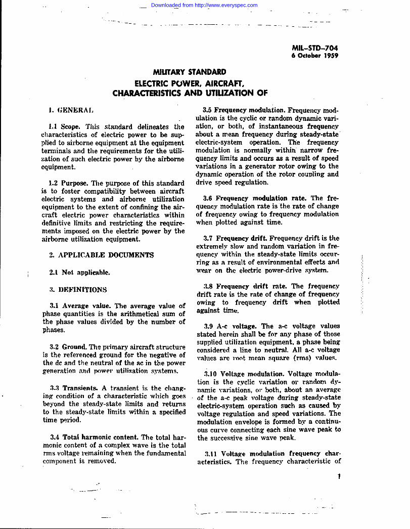
l’ABIJC IL Steadu-state d-c voltage limi&
‘$ *E c, Thesea?tedCO”diti,,n.ofUircr.ftoperation*,,withinthe“O,malmod,ofClectriesmtem.bwrau.m.2After3 mimtu of ..M ad W.,nmp .irc,tit .aWrnti.an, OK sti&sab d~e EE.Jti da b wje,h *, Bmlts med
1., tdm,m .aml’ma.m.1 Wheresimraftlanding.pernt;.msb..,dmratio.sexceedinz5 min.tm thewider v.hge linlitfallowedforIa.dlncsMI &
randn beyondtheumi” ,Ilowcdformu],.f.,m.ratb,r,6u,ir,utes.
sequence of A, B, C corrcaponding to T, — T,— T, of the power source. Figure 4 diagramsthis relationship.
5.2 D-c prover system characteristics
5.2.1 Steady-state vottage. Steady-state volt-age shall be within the ltilts specified intable II.
5.2.2 Ripple. The a-c peak of ripple voltageto average d-c voltage (see 3.12) shell be lessthan 1.5 volts, when measnred with a peakreading vacuum tube voltmeter in series witha 4.0 microfarad capacitor. The higher of thetwo values measured when the voltmeter issuccessively connected for each of two polari-ties shall be considered the ripple voltage.
5.2.2.1 FrequenmJ ciwacteristics. The fre-quency components of the ~ipple shall be with.in the limits of figure 5 when measursd asconductd interference.
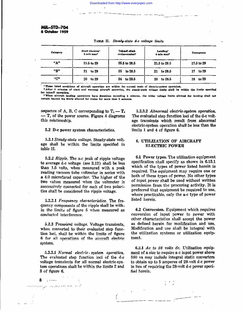
5.2.3 ?%ansid voltage. Voltage transients,when converted to their evaluated step func-tion loci, shall be -within the limits of tigure6 for all operations of the aircraft electricsystem.
3.2.3.1 h’owud electric- $qIstem operation.The evaluatsd step function ioci of the d-cvoltage tranaienta for all normal electric-sys -tern operations shall be within the limits 2 and3 of figure 6.
8 :---- ~~
5.2.3.2 Abnormal efectric-.vftstem opew%n.The evaluated step function loci of the d-c volt.age transients which result from abnormalelectric-system operation shall be less than thelimits 1 and 4 of figure 6.
6. UTILIZATION OF AIRCRAFTELECTRIC POWER
6.1 Power types. The utilization equipmentspecification shall specify as shown in 6.13.1which of the types of power listed herein isrequired. The equipmeut may require one orboth of these types of fmwer. No other typesof inpnt power shall be used witbout writtenpermission from the prccnring activity. It ispreferred that equipment he required to use,where practicable, ordy the a-c type of powerlisted berein.
6.2 Conversion, Equipment which requiresconversion of input power to power withother characteristics shall accept the poweras defined herein for modification and use.Modification and use shall be integral withthe utilization systems or utilization equip-ment.
6.2.1 Ac to ~8 VOW dc.Utilisation equip-ment of a sise to require a-c input power above500 va may include integral static convertersto obtain up to5 amperes of 28-volt d-c pawerin lieu of requiring the 28-volt d-c power speci-fied herein.
,, -
.._ —-—— —--—————.—
Downloaded from http://www.everyspec.com

.-
._._—
—-—
—.
....
...
----_,
MIL
-STD
-7046
October
1959
awe,
-.N
-.00
00
.—.-
W*
Cu
00
0~oo
00
00
0
S11OA
SH8
0
0Wo*o
.Ejo00
/.. ,”.
—.
.-.—
-
Downloaded from http://www.everyspec.com
MIL
-ST
D-704
6-r
1959FPc
;it
:1%
;
————
.-—
.—
.-T[l–
.—
/—
—/ —
.—
——
—\ ——
—i
10..
..
—-.
...
.—.
-----
.,----—
——
_
Gw(n
usi=
Downloaded from http://www.everyspec.com

-.
6.6 Normat electrtc-eystem operation. Dur-tng normot operation of the electric system(See 5.1.6, 5.1.4.1, 5.1.5, 5.1.6.1, 5.2.1, end5.2,2.1), utilization equipment shall:
(a) Mvide 100-percent performance,except when the detail specifica-tion for a given utilization equipment defines specitic regions ofthe electric system characteris-tics with corresponding degreesof performance degradation (see7.8).
(b) Remain safe.
(c) When degraded performance beebeen permitted for gtvon regionsof given characteristics, after OPeration in such regions with r+turn to other regions of normalelectrbsystem operation, the nti-tisation equipment shall:
(1) Automatically recover to 100-percent performance.
(2) Remain unaffected in reliabil-ity.
6.4 Abnormal electric - system operation.M abnommt operation of the electrhsystem (see 5.1.4.2, 5.1.6.2, end 5.2.3.2) utiti-cation equipment:
(a)
(b)
(c)
(d)
Shell have no performance require-ments, unless the detail speeifi-tion for a given utiiation equipment requires specific degrees ofperformance to be maintainedwithin specific regions of the elec-tric-system charasteristfss (see7.6) .
Shrdl remain safe.
May have momen~ 10SS of fonc-tion; however, this momentaryloss shall not atTect later equipment performance.
After abnormal operation of theelectric system and with returnof the ekcti:c system to normaloperation, utilisation equfpmentshall :
(1)
(2)
—
MIL-STD-7046 Oetobr 1959
Recover automatieeuy to apeet-tkd performanq mdese thedebit epeddcation for agiven utitisation equipmentPermitS IUSUUSI reset ofequipment after the abnor-mal electric-system operation.
Have negligible effest on reli.ability owing to,the abnonnatelectri*syetem operation.
6.5 Other electric-system operation. Whilethe electric system operatea in regions ofcharacteristics other than specided in section5, utilisation equipment shalt:
(a) Not be required to perform.
(b) Not be required to perform afterreturn of the electric system intothe regions of characteristics spe-cified in sestion 5.
6.6 Voltage transients. For the purpose oftesting performance of utilization equipmentduring conditions of input voltage tilents,voltage transients shatl be mnsidered se anyvoltage at its corresponding time on thelimits of figures 2 and 6.
6.7 Warmup. Time required for equipmentto warmup prior to obtaining speciSed par-formence shall be kept to e minimum. ‘l%neto return to specified performance, after apower interruption, shall not exceed the ac-tuat thermal or mechanical requirements, orboth, Warmup shall he leas than 5 minutesunless approved in wrtting by the procuringactivity.
6.8 In6qence on electrtc system. Thereshatt be no influence by utilization equipmenton the cherastmistics of power at the inputto its terminals which would cause thesecharacteristics to go beyond the limits epeci-tted in sedion 6.
6.6.1 Setf+lodukzfiox The modulation in-duesd by vruying loads within utilisationequipment shaS not at the ti “ of theutiSsettOn equipment, cause voltage moduIa-
11
. . . -.
‘...—-.
...— . . . . —. — ———. — —.. _ /–-— —.
Downloaded from http://www.everyspec.com
. __. —... .—-.
MiL-sfD-7046 October 19S9
tion or ripple to go beyond the limits of5.1.3.6 and 5.2.2. This self-mwhdation is caus-ed by variations in the current reqnircd by
: the equipment, in turn causing a varyingvoltage drop in the wiring of the power cir-cuit to the equipment.
6.9 A-c power.
6.9.1 !Thrwephase. For loads less than 500~a, 3-phase power shall be nsed when prac.tirable. Fm- a-c input demands excesding 500va, 3-phsse power shall be required. The aver-age of three phases st.eady+tate voltage limitsin table I are applicable only when a phase ofthe three phases is not utilizsd as a single-phsse lead.
6.9.2 Single phae. For a-c input demandsnot exceeding 500 va, it is allowable for theequipment to require single-phase power.Equipment which is inherently single phasein pewer consumption shall present, if practic-able, a three-phase demand by being internallySCgrCgS@d into three singk-phase loads. Sin-gle-php~ pewer shall be M only on a line-to-neutrsl basis.
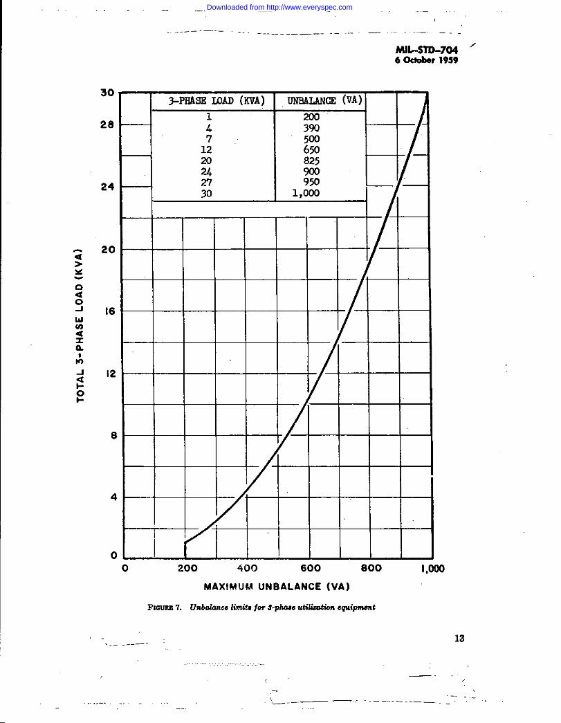
6.9.3 Phase fmkmce. Equipment requiringthree-phsse power shall rsquirs sqns} phasevolt-am- and power factor insofar aspracticable. The pk~e volt-ampere differencebetween the highest and lowwt phase values,assmning bslsneed voltages, shafl hc les thanthe limits specified in figure ‘7.
6.9.4 Power fader. Equipment utilizing a-cpower shall be designed to present as near aunity pawer factor & practicable for all modesof equipment operation. The fully loadedequipment shall present a power factor on theworst phase not les9 than the limits spccifisdin figure 8.
6.9.5 Phu.re faikre. One phase of three-phase power can fail. Failure of one phaseshall not result in an unsafe condition. Duringfailure of the one phase, no cqnipment per-formance” is requirsd unless speei3ed in theequipment detail spccifleation.
,, M..~–---
-, .--—
—
6.10 Power failure. For those eqniprnentawhich require both a-c and d-e power, oneof these power sources may fail. Failure ofone power source shall not result in an unsafecondition. During the loss of the one powersource, no equipment performance is ra-quired.
6.11 Standby power. For those modes ofequipment operation in which performance isnot required but power ia required to msin-tsin equipment standby readiness, the stand-by power requirement should bc kept to aminimum.
6.12 Puwer tolerance. Input power require-ments shall not vary by more than + 10 per-cent and – 10 percent of an established limitbetween production units of a given utilisationequipment. The specified tolerance Itilta do notinclude changw in equipment power demandsas a resnlt of engineering changes rnsde dur-ing production.
6.13 Power requirements data (requiredfor Navy equipment only). Power requirement data shall be submitted to the procur-ing activity. The data shall be successivelysubmitted as soon as available based on:
(a) Specification requirements.
(b) Preliminary design data for theequipment.
(c) Measurements made on the firstmodels.
(d) Measurements made on representa-tive production units.
(e) Power requirements revisions CSU5ed by proposed equipment changes.
NOTE: When the Air Force is the procur-ing activity, a copy of the power re-quirements data shall be submitted tuthe Wright Air Development Center,Wright-Patterson Alr Force Base,Ohio; Attention: WCLES.
6.13.1 Sampfe form. The sample form forsubmittal of the power raqn~ements data shallbe os shown on figure 9. It shall be submittsd
,—.. .—— — —- --
‘\_____ ——
Downloaded from http://www.everyspec.com
30
28
24
20
16
12
6
4
0
..- —-— — ,.. . —
MIL-STD-704 ‘6 Octeber 19S9
r3-PII.4SE WAD (KVA)
i7
12202A
-1 i+30
UNR4LANCE(VA)
200390
E825900950
1,000
0 200 400 600 600 I,Ooo
MAXIMUM UNBALANCE (VA)
FXOUFZ 7. VnbaknceIimti for @uue utikiim 6Qt{w$71t
13_— -
,,—..
:. ,
__ -—. .. --——.--—.-—— _
Downloaded from http://www.everyspec.com

. ...
——— —--- —- +-. _
hU1-STD-7046 O@ober 19S9
nuoJa>x
E1-Ua
30.0
2.0
1.8
1.6
CATEOORYflAfl ANO ‘Btt ncl!
P.F . KVA P.F. KVA0.10 0.025 0.10 0.0250.30 0.090 0.30 0.1200.50 0.200 0.40 0.3000.65 0.400 0.46 0.6000.75 0.750 0.50 1.000.7530.0 0.5030.0
i I t 1 I
0.4 ———
0.2
0.1 0.2 o.~ 0.4 0.6 0.8 1.0
POWER FACTORFISVIW8. &gp”ngpowerfactor limiti for utilizationequimt
on 8 by 10Y2 sheeta. Inetroctions for complet- (c) Enter braekete at the tep of theing the form shall be as follows: power requirements cokmms “M”
(a) Cross out category of equipment notfor measured, “C” for calculated,or “R” for referenced. to indicate
(b) Fill in brecketa to indisste mode ormedes of equipment operationsuch as Warmnp, Standby, Oper-ate, ‘Low Power, Power DutyCycle, Start, etc. Prepare sepa-rate load requirement data foreach mede of operation.
the source of information. Refer-erence “R” can be detailed in theline “Source of Information” orunder “REMARKS” as applicable.
(d) Under “Operating Time” enter oper-ating time for the correspondingmode. Strike out “(min)” or“ (SSC)” se applicaMe. Under “Spe-
14
L—. .. —.! -.. . .
Downloaded from http://www.everyspec.com
,. .-—-. --—.. ,.,
died” write the specified time forthe mode of operation being re-ported.
(e) If the operation is cyclk deecriithe cycle under “Note.”
(f) The rower reouirementa shall be. .
(d
(h)
(i)
(j)
rnekeured in ~line-tmieutral basiswith the reference voltage aadfmquoncy applied to the termi-rude of the equipment and entwedin the appropriate spaces. A-emeasurements shall be efTectivevalues (rme), with an aeeuracy ofat least 1 percent. D-e meaeur+ments should be accurate to 8Aof 1 percent. The angle enteredunder ~ shrdl be the angle b+tween the corresponding line cur-rent and the line A to neutrrdvoltage.
When the current lags, the voltage,vars and PF shall be enteredwithout sign; when the current isleading, these items &l] ho boxedes indicated in the following ex-
ample: ~
All power requimmenta entriesebaU be the steady+tate demandfor the mode of operation rep=mt-ed. If unusual changes in powerdenmnd occur during a givemmode of operation, description ofthe conditions and demende shallbe made under “REMARKS.”
Power requirements for utilizationequipment whose application willdetermine the input pewer shallbe baaed on full-load (nameplate)rating. Conditions of loading ver-eus power demand shall be ex-plained under “REMARKS.” Pow-er reqnimmente for intermittentdnty equipment shall have thereted duty cycle deacriied under‘%EMARKS.”
If the equipment has trsnsient pow-er requirements, an oecillographic
.r -—-—
.---”” “—-—““‘—
(k)
(1)
——-—. . . _
MLS7D-7046October19S9
recordof currentveranstimecharacteristicsshallbepresentedes supplementary data Thesedata are not a reqnkmant forloads rated lees than 600 va or 20amperes dc.
Description of any internal electri-cal protective devices shall belisted under “REMARKS.”
information may be included under“REMARKS” regarding Subehlll.tird improvement of utilisationequipment performance, reltabd-ity, weight. ~d ske beyond apeei-tication requirements by main-taining charackistica differentthen specified herein under s-tion 5. If possible, the degrees ofimprovement corresponding tochanges of the given character-istics should bo listed. Note under“REMARKS” sny unusual or uni-que power conditions, data, orlimits which will aeeist the appli-cations engineer in determiningthe proper application of theequipment. Information, whenknown, shonld be inclndod to indi-cate maximum or minimnm (orbotb) power source impedancelimitations for satisfactory equip-ment operation.
7. NOTES
7.1 Normal electrtwyatem operation, Nor-mal operation of the electric system are altfunctional electrksyeteln operations requtr-ed for airersft operation, eireraft mission
,and electric-system controlled continuity.These operations eecur at any given imtantand any number of times during tlight prep.eretion, takeoff, airkorne eonditione, landing, ,and CUChOri~. ExamPle9 Of SUCb OPWStiOllS
are ewitcbing of utilisation equipment load%~tif ~ ch~gee, bus A- and ayn-&mmzation, and pamlleEmgof electric powersources.
15
.
Downloaded from http://www.everyspec.com

—.
-. ———- ..-— ------- —. -._—
MIL-STLL7046 October1959
SECURPTY CLASSIFICATIONELECTRIC POWER REQUIREMENTS FOR AIRCRAFT EQUIPMENT:
SHEET OF
EQUIPMENT CATEGORY (WA”) (“B$)) (’tC”)
5 SECOND NAX POWER REQUIREMENTS FOR ( ) MoDE (S)OF OPERATION
2*F ‘%=, %2E 2
REMARKS: InrushtransientshowncmsupplementarydatasheetNo.
1 MINUTE MAX POWER REQUIREMENTS FOR ( ) MODE(S) OF OPERATION
3’EE =+==%%
REMARKS : InrushtransientshownonsuppkunentavdatasheetNo,
:,15MINUTE POWER REQUIREMENTS FOR ( ) MODE(S) OF OPERATION
lF-’#-E+=E G :
REMARKS : InrushtransientshownonsupplementarydatasheetNo.
MANUFACTURED UNDER SPECS :
DeviationsAffectingPowerData Authorized by I Refermce
; Is.
SOURCE OF 1NFORMATIONUnlessotherwisestatedherein,thisequipmentconformstotherequirementsofMIL-STD-704.
SIGNED : _
DATE :
COMPANY:(Army) (BuAer) (AirForce)
APPROVED : DATE :
FIGURE9. .%mpk form for 8ubmitW of powerrequirementsdata
16.——.. —--—
—., —-—— -. ..—_. ._
Downloaded from http://www.everyspec.com

.—..—..
7.2 Abnormat eketrfc - system operation.Abnormal operation of the electric system isthe unexpected but momentary loss of con-trol of the electric system. The initiatingaction of the abnormal Operetiori is uncon-trolled aud the exact moment of its occur-rence is not anticipated. However, recoveryfrom this operation is a controlled action.Tl!is operation occurs perhaps once during a
, flight ores a result of battle damage or it: may never occur during tbe life of an air-~ craft. Ari example of an abnormal operation! is the faulting of electric power to the struc-~ ture of an aircraft and its subsequent clear-: ing by fau!t protective devices.
7.3 Emergency electric - system operation.~ Emergency operationisdefinedas thatcon-: ditionof the electricsystem during flighti when the primary electricsystem becomes; unableto supplysufficientor properelectric
power, thus requiring the use of a limitedindependent alternate source of power.
7.4 Reference voltage. For the messuwment of input power and calibration of utili-sation equipment. the following referencevoltages shall he used:
(a) 115 volts line-to-neutral for the115/20C-vOlt a-c system.
(b) 28 volts lin~twgrcmnd for the 28-Volt d-e SYStelll.
7.5 Reference frequency. For the meas-urement of input pewer and calibration ofutilisation equipment, the reference fre-quency of 400 cps shell be used.
7.6 Conversion of a transient to its evsJu-ated step function leei. On a basis of con-verting a complex voltage transient (V.)into a function of ite reasonable equivalentrms on a continuous basis (f V. (~) = V.),the basic formulae used for the conversionare:
~-.
—-——- - ‘-
MIL-S7D-7046 October 19S9
where: V.= Variable transient voltagese a fnnetion of time,
t.= Total tbne being consideredon a continuous bssta,
V.= Voltage at ~ which pro-vides an equivalent stepfunction of the transientfrom zero to t.,
T.= Time at a value of V. beingconsidered wti]ch providesan. equ@lent stip fmwtion of the previous partof the transient.
AT= Arbitrary tibne incrementsused to convert the tran-sient to a step functionloci,
V,= Voltage at the start of theA t increment.
V,= Voltage at the end of theA t increment.
Zem time is the start of the transient endis considered to be the point in tbne whenV. initially changes from one Wr unit. Forall transients occurring in the normal modeof ekctric-system operation, the peak voltageor minimum voltage is reached very rapidfy.Evaluation of these traAerda should reflectthe minimum or maximum readwd by con-sidering the transient starting at the maxi.mum or minimum voltage fmm time cam(start of transient) until its coinr %nce ofthe actual transient. !tle coincidence is shownas point A in figure 10. Figure 10 is a samplecoiwersion of an overvoltage transient to iteevaluated step function loci
7.6.1 Fanft trenefenta. The conversion ofa fault transient to its step function ledshould be made on a continuous basii fromtime zero (initial time at start of the tran-eient). Conformance to the reqairament shallbe indicated by the step function loci of thefault transient remaining @thin the Iirnitafor ahnormrd mode of electric-system oPsrs-tion of 6gures 2 end 6. Additionally, confonn-
17
...—..—
_—. — ---
Downloaded from http://www.everyspec.com

MIL
-STD
-7046
Octobw
1959
,...—
—.—
.
G’
SL-IO
ASW
M
..?-—
.,.-,.\.,
_-......
--
Downloaded from http://www.everyspec.com

.- .—‘:. “>. - —— ._ .. .._.,, _ . ... . . . . ._.
MIL-STD-7046 O@eber 1959
ITEML MIL-S~704 POWER REQUIRED (AC) ~
2 MILS~704 POWER REQUIRED (DC)
S. O~ER TYPE POWER REQUIRED
4. CATEGORY’IA*EQUIPllENT
& CATEGORY”B” EQUIPMENT
S. CATEGOItYllC”EQUIPMENT
7. DURING NORMAL 0PER4TION, REGIONS AND DEGREES OFDEGRADED PIilRFORMANCE ARE PERMITTED
8. DURING ASNORMAL OPERATION, REGIONS AND DEGREE6 OFPERFORBL4NCE ARE REQUIRED
9. MANUAL RESET 1SPERMITTED AFTER ABNORMAL OPERATION
10.FULL EQUIPMENT PERFORMANCE IS REQUIRED FOR TEEFOLLOWING AIRCRAFT OPERATING CONDT?IONS:
START AND WAIUdUP
TAKEoFF AND CLIm
CRUISE AND CRUISE-COMBAT
LANDING
EMERGENCY
11.EQUIPMENT PERFORMANCE ISRBQUIRED WITB LOSS OFFOWERFROMONE PHASE
w
NOTES : .
FImnm 11. SkmdaniDIIL-STD-704mu Afirotien.Ad&M8t
snce shoti,d be obtained in that the actualfa~t volta~e should not exceed the minimumor msxim@n step function voltages specifiedin f@res 2 and 6.
7.7 Line drop compensation. Upon specificapproval from the procuring activity, thecategories “A” and “B” utilization equip
ment may incorporate means to compensate
for line drop.Itispreferred that the meansconsist of taps brought out to the input pow-er connection for selection at time of instal-
lation.
7.8 Equipmentequipment detail
detail epeeikttion. Thespecification may use the
checkoff listiltuetrated in tlgure 11 to specifpconsiderations applicable to tbie %ndard.The notee detail the qualifying especta foreach item.
7.9 Assumptions.
7.9.1 SmaileatVAmamlelectric euetem. The
50 sm~ dc
7.9.S Ekctric-euetem bahce. Balance mthe cketric system is withii 15 percent i.~,no linen are loaded so that the maximum vaditYerentislbetween linca is more then 15 per.cent of ~ the %phase vs capacity.
19___—
—
Downloaded from http://www.everyspec.com
—..
MIL-STD-7046 OdOber19s9
7.9.3 Gen@ating+@em duznwteridiea. NO
generating-ayatem Chars&m “ tic is consideredunless it is usual and normal for the genemt-ing system to be tied to the bus at tbe timethe charackriatic becomes evident.
7.9.4 Efectrk-s@em ckmw%riaticg. Char-acteristicscoveredin thisstandmd are basedon the eleetric+yatem power source being:
Hydraulic (constant speed drhe)Air turbine (constant speed drive)
Mechanical (constant apeed drive)
TurbopropInverters
Transformer-rectifiers
Batteries supported by generatore
7.9.5 Normal loading. Normal leading of anelectric system is between 15 percent and 35-t of the power-web capasity and willbe 30 to 85 percent for cruise-combat con-ditions.
7.9.6 Inittid wwfmup. Initial warmup (first5 minutes) is not inclusive with takeeff, clii,cruise-combat, and landing aircraft opera-tions.
7.9.7 System power factor.System powerfactor during cruise, and crniee-eembet air-
craft operations will be more than S5 perwnt.
—--- —–
7.9.8 Power-s@era rating. Power SJL9b15
will be rated from discreet capaeitks such as1.5, 2.5, 10, 20, 30, 40, 60, 90, and 120 kva acand 50, 100, 200, 300, and 400 sm~ dc.
Notiea When Governmentdrarvin~specifications,orotherdataareussdforanYPurpcwotherthaninconnectionwitha definitelyrelatedGovernmentPr-ocurement.operatkm,theUnikd StatesGovernmenttherebyincursno responsibilitynorany obligationwhat-sower;andtbefactthattbeGovernmentmayhaveformulated,furniabcd,orinanyway supplkdthesaiddrawings,specifications,orotherdataisnotb bercgardsdbyimplicationorotherwiseasinanYmannerlicensingtheholderoranyotherpersonorcorporation,or conveyinganyrightsorp+rmimiontimanufacture,use,orsellanypatentedinventionthatmay inanyway berelatedthereto.Copiesof.mecidsntions,stnndanls,drawings,and
publicationsreqnircdby contractorsin connectionwithspecificprocurementfunctiomshouldbe o!+tainedfromthepremriagactivityorssdir.cctcdbythecontractingofficer.Copicaofthisstandardformilitaryusemay be
ohtafnedasindicatedintbeforewordto@e Indexof MilitarySpecifications and Standards. .:
Copiesofthisstandardmay bsobtainedforotherthanofficialuseby individuals,firms,andCO?ItrSC-tors fmm the Superintendentof Documen+,U. S.GovernmentPrintingDf?ice,Washingtons5,D. C.
PreparingSA.ity:Nmv—B-m ofAuvmmItim
Othercustodians:Army-Trammortatic.nGxpsAirForce
,., ~
20 “’”-- 0,..,s..6-,
\,- !,—.
Downloaded from http://www.everyspec.com


![D STD ]STD W T STD WXŒP ST DDDDD ...d ˙˛~q˚std˙˛ tw•p˛]std˙˛w_t˜ std˙˛wxŒp st ddddd (¤ dfid˙˛ƒtw]std˙!ƒstdddddddddddd dddddddddddddddddddddhµµµµµµµ! xstd⁄n"]std#wt˜x](https://img.dokumen.tips/doc/110x75/5f0a52c07e708231d42b1742/d-std-std-w-t-std-wxp-st-ddddd-d-qstd-twapstdwtoe-stdwxp.jpg)