Embed Size (px)
Citation preview

MIL-STD-1599NOTICE 17 October 1982
MILITARY STANDARD
BEARINGS, CONTROL SYSTEM COMPONENTS, ANDASSOCIATED HARDWARE USED IN THE DESIGN
AND CONSTRUCTION OF AEROSPACE MECHANICALSYSTEMS AND SUBSYSTEMS
TO ALL HOLDERS OF MIL-STD-1599:
1. REPLACE OR ADD THE FOLLOWING PAGES TO MIL-STD-1599:
NEW PAGES DATE SUPERSEDED PAGES DATE
v thru vi 7 Oct 82 v thru vi 31 Jan 80202.1 thru 202.24 7 Oct 82 N/A301.1 thru 301.2 7 Oct 82 N/A
302.1 7 Oct 82 N/A308.1 thru 308.3 7 Oct 82 N/A
2. RETAIN THIS NOTICE AND INSERT BEFORE TABLE OF CONTENTS.
3. Holders of MIL-STD-1599 will verify that page changes and additionsindicated above have been entered. This notice page will be retained as acheck sheet. This issuance, together with appended pages, is a separate“publication. Each notice is to be retained by stocking points until theMilitary Standard is completely revised or cancelled.
Custodians:Army - AVNavy - AS
Project 31GP-0014Review activities:
DLA - IS
Preparing activity:Air Force - 11
Downloaded from http://www.everyspec.com

Downloaded from http://www.everyspec.com

Requirement
201202203204205206207208209210211
Requirement
301
302
303
304305306307
308309310
311312
Title
Requirement
401402
*Requirement
MIL-STD-15997 October 1982
SECTION 200 - GENERAL DESIGN REQUIREMENTS
Date ofPublication Title Page
31 January 1980 Bearing Usage 1/ 201.1
7 October 1982 Bearing Retention 202.1* Component Lubrication
31 January 1980 Bearing Safetying Practices 204.1* Ball Screw Usage
31 January 1980 Control Cable System 206.131 January 1980 Control Rod System 207.1
* Push-Pull Controls System* Shaft and Pressure Seal Usage* Universal Joints and Flexible Couplings* Latch Mechanism Design
SECTION 300 - AIRFRAME BEARINGS
Date ofPublication
7 October 1982
7 October 1982
31 January 1980
**
31 January 198031 January 1980
7 October 1982**
**
Airframe Bearings, Ball,Antifriction
Airframe Bearings, AntifrictionRoller
Antifriction, Needle, includingTrack Rollers
Antifriction, MiniatureFluid FilmSpherical, All-metalSpherical, Non-metallic and
Non-metallic LinedRod EndsJournal and Bushings, All-metalJournal and Bushings, Non-Metallic
and Non-metallic LinedLinear Motion, AntifrictionSpecial Purpose Designs
SECTION 400 - BEARING RETAINER RINGS. WASHERS. NUTS
Date ofPublication Title
* Retainer Rings* Tab Washers, Nuts, and Locking Devices
not as yet published
Page
301.1
302.1
303.1
306.1307.1
308.1
Page
1/ Due to the length of this requirement, a table of contents is included forconvenience.
v
Downloaded from http://www.everyspec.com

MIL-STD-15997 October 1982
Requirement
501502
Requirement
601602603604605606
Requirement
701702
Requirement
801802
Requirement
901902
SECTION 500 - GREASE/OIL SEALS, NON-INTEGRAL
Date ofPublication Title
* Grease Fittings* Shaft Seals
SECTION 600 - CONTROL CABLE SYSTEMS
Date ofPublication Title Page
31 January 1980 Control Cable Assembly Components 601.131 January 1980 Control Rods 602.1
* Pulleys, Rollers, Fairlead* Bolts, Shaft, Dual Safetying* Environmental Pressure Seals* Push-Pull Controls
SECTION 700 - LATCH COMPONENTS
Date ofPublication Title
* Bearing Shaft Bolts* Nuts
SECTION 800 - BALL SCREWS AND SHAFTS
Date ofPublication Title
* Ball Screws and Shafts* Mounting Criteria
SECTION 900 - MECHANICAL DRIVE COMPONENTS
Date ofPublication Title
* Universal Joints* Flexible Couplings
*Requirement not as yet published
vi
Page
Page
Page
Page
Downloaded from http://www.everyspec.com

MIL-STD-1599REQUIREMENT 2027 October 1982
BEARING RETENTION
1. Scope. This requirement establishes engineering criteria and designinformation relative to the installation and retention of bearings tofacilitate their proper airframe usage (see requirement 201). Included in thetext will be information concerning the various techniques for installing eachclass of airframe bearings in the various housing materials which may beencountered in an airframe. Where applicable, this requirement will alsopresent engineering criteria and design information relative to the removal andreplacement of airframe control bearings.
2. Documents applicable to requirement 202
QQ-P-416 Plating, Cadmium (Electrodeposited)MIL-A-8625 Anodic Coatings, for Aluminum and Aluminum AlloysMIL-STD-889 Dissimilar MetalsMS14101 Bearing, Plain, Self-Lubricating, Self-Aligning, Low-
Speed, Narrow, Grooved Outer Ring, -65°F to 350°FMS14102 Bearing, Plain, Self-Lubricating, Self-Aligning,
Low-Speed, Wide, Grooved Outer Ring, -67°F to 325°FMS14103 Bearing, Plain, Self-Lubricating, Self-Aligning,
Low-Speed, Wide, Grooved Outer Ring, -65°F to 325°FMS14104 Bearing, Roller, Rod End, Internal Thread, Self-Aligning,
Low-Speed, Narrow, Chamfered Outer Ring, -65°F to 325°FMS21220 Bearing, Roller, Rod End, Internal Thread, Self-Aligning,
Anti-Friction, Airframe, Heavy Duty, Type II, -67°F to250°F, Sealed
MS21221 Bearing, Roller, Rod End, External Thread, Self-Aligning,Anti-Friction, Airframe, Heavy Duty, Type I, -67°F to250°F
MS21429 Bearing, Roller, Anti-Friction, Rod End, External Thread,Self-Aligning, Airframe, -67°F to 350°F, Type I, HeavyDuty, Sealed
MS21431 Bearing, Roller, Self-Aligning, Single Row Anti-Friction,Sealed, -65°F to 350°F, Type I
MS21432 Bearing, Roller, Needle, Track Roller, Integral Stud, TypeVII, Anti-Friction, Inch
MS21438 Bearing, Roller, Needle, Single Row, Heavy Duty,
MS21439
MS34461
MS24463
MS24464
MS27640MS27641MS27642MS27643
Self-Aligning, Type III, Anti-Friction, Inch, SealedBearing, Roller, Needle, Double Row, Heavy Duty, TrackRoller, Type VI, Anti-Friction, Inch, SealedBearing, Roller, Needle, Single Row, Heavy Duty, Type I,Anti-Friction, InchBearing, Roller, Needle, Single Row, Heavy Duty,Self-Aligning, Type III, Anti-Friction, InchBearing, Roller, Needle, Double Row, Heavy Duty,Self-Aligning, Type IV, Anti-Friction, InchBearing, Ball, Airframe, Anti-Friction, Heavy Duty,Bearing, Ball, Airframe, Anti-Friction, Intermediate DutyBearing, Ball, Airframe, Extra Light DutyBearing, Ball, Airframe, Anti-Friction, Self-Aligning,Double Row, Heavy Duty,
202.1
Downloaded from http://www.everyspec.com

MIL-STD-1599REQUIREMENT 2027 October 1982
MS27644
MS27645
MS27646MS 27647
MS27648
MS27649MS28912
MS28913
MS28914
MS28915
Bearing, Ball, Airframe, Anti-Friction, Double Row, HeavyDuty,Bearing, Ball, Airframe, Anti-Friction, Self-Aligning,Light and Heavy Duty,Bearing, Ball, Airframe, Anti-Friction, Extra Light Duty,Bearing, Ball, Airframe, Anti-Friction, Extra Wide, DoubleRow, Intermediate Duty,Bearing, Ball, Airframe, Anti-Friction, Externally Self-Aligning, Extra Light Duty,Bearing, Ball, Airframe, Anti-Friction, Intermediate Duty,Bearing, Roller, Self-Aligning, Single Row, Airframe,Anti-Friction, Sealed, Type IBearing, Roller, Self-Aligning, Double Row, Airframe,Anti-Friction, Sealed, Type IIBearing, Roller, Self-Aligning, Double Row, Wide InnerRing, Airframe, Anti-Friction, Sealed, Type IIIBearing, Roller, Self-Aligning, Double Row, Torque Tube,Airframe, Anti-Friction, Sealed, Type IV
3. General. A bearing is a machine element intended to permit a load to betransmitted from one structural member to another, while at the same timepermitting relative movement between the two structural members. Incorrectbearing installation and retention can result in a reduction in bearing usefullife, an increase in bearing operating torque, or irreparable damage to thehousing or bearing components. Proper installation and retention techniquesand processes shall be used to assure proper bearing performance. Regardlessof the type of bearing being installed, preinstallation precautions shall betaken as follows:
a. The installation area shall be clean so that contaminants do not come intocontact with the bearing.
b. Assembly tools and fixtures shall be maintained in good working condition.
c. Bearing shall be kept in their protective packaging until time ofinstallation.
d. The housing bore shall be free from all metal chips, filings, and otherforeign material.
3.1 Corrosion considerations. Galvanic corrosion occurs when two dissimilarmaterials are in contact in a medium capable of carrying electrical current.Requirement 105 of this document describes the procedures for preventinggalvanic corrosion. In addition, table 202-1 of this requirement outlines somerecommended treatments.
202.2
Downloaded from http://www.everyspec.com

MIL-STD-1599REQUIREMENT 2027 October 1982
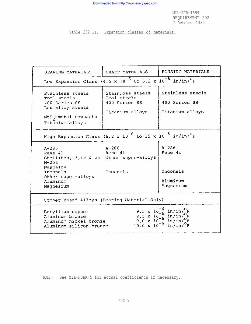
3.2 High temperature considerations - differences in expansion co efficient.Expansion coefficients of bearings, shafts, and housing materials are, in manycases, radically different and must be carefully considered when mountingbearings. Some typical ranges for expansion coefficients are shown in table202-11. Figure 202-1 demonstrates the expansion differences that occur whenbearings, housings, and shafts of different expansion characteristics are usedat elevated or cryogenic temperatures. In many cases, the expansioncoefficient match determine the bearing material selection. The selection ofmaterials of similar expansion characteristics of bearings, housings, andshafts is preferable to using complicated mechanical retention methods.Bearing, shaft, and housing materials can be divided into two classes accordingto their expansion characteristics. In general, materials in the same classcan be used together without expansion mismatch problems if bearing diametersare small, if operating temperatures are not extreme, or if radial playrequirements are not critical. Care must also be used in selecting rollingelement materials which vary in expansion coefficient from the race materials.A change in bearing radial play will be evident as the temperature is raised orlowered. Spherical bearings constructed of different ball and outer racematerials must also be provided with the proper radial play to compensate forexpansion differences. The usefulness of the interference fit method ofmounting for high temperature bearings depends on the difference between theexpansion coefficients of the bearing and the shaft or housing. The practicalmaximum that can be tolerated is a difference in expansion coefficient ofapproximately 1.0 x 10⁻⁶ in/in/°F. This expansion difference could give arelief of 0.0005/in of diameter to a press fit at an operating temperature of600°F and 0.0018 at an operating temperature of 1900°F.
4. Installation
4.1 Method of installation. Use thebearings. Apply pressure only on thehousing or shaft. Figure 202-2 shows
proper tools and procedures to installrace of a bearing in contact with theproper methods of installing bearings.
4.2 Shaft and housing fits - rollinq element bearings
4.2.1 Proper fit of a rolling element (anti-friction) bearing is a criticalfactor in bearing life. Most bearings have sufficient internal clearance topermit an interference on either shaft or housing. An interference fit in bothplaces may preload the bearing. A slight preload can improve bearingperformance as it improves the load distribution within the bearing while alarge preload could reduce bearing life.
4.2.2 Airframe ball and roller bearings (see requirements 301 and 302) arecustomarily mounted with a clearance fit between the shaft or pin and the boreof the inner ring. With the exception of torque tube bearings (see requirement201, Bearing Usage), the outer ring is press fit into the housing and retainedin the axial direction by staking or other mechanical means. When light alloyhousings are used, the axial restraint mechanism used becomes extremelysignificant due to the difference in thermal properties between the bearing andhousing materials.
202.3
Downloaded from http://www.everyspec.com

MIL-STD-1599REQUIREMENT 2027 October 1982
4.2.3 Press fit installation should be avoided when mounting either the inneror outer rings of a torque tube bearing (see requirement 201, Bearing Usage) inorder to prevent an excessive bearing preload. A line-to-line or clearance fitshould be used between the housing bore and bearing outer ring with suitableaxial restraint by staking or other mechanical means.
4.2.4 In many airframe bearing applications, the shaft revolves (oroscillates) and the housing remains stationary in relation to the direction ofthe radial load. Recommended shaft and housing fits for this type ofapplication, for average operating conditions are shown in tables 202-111through 202-IX.
4.2.5 The required fit of the inner ring on the shaft will vary with theapplication and the service. In some series only housing fits are shown, asthe bearings listed do not require a precise fitting on the shaft.
4.2.6 Recommended housing fit varies with bearing series, and varies withhousing material within any series. Also both shaft and housing fits arerecommended for some series since these bearings have a wider range ofapplication than most airframe bearings.
4.2.7 Recommended housing bore tolerances shown in tables 202-111 and 202-VIthrough 202-IX will usually result in satisfactory installation when used inconjunction with the internal clearances shown in the bearing listings of themilitary standards shown in the requirement 302 for this type of bearing. Thefinal running fit, within a bearing of this nature, is dependent on manyfactors, such as: the individual housing design, bearing internal clearance,housing material, operating temperature and the amount of interference betweenthe bearing and the housing.
4.2.8 The outer ring sections of many annular bearings are thin enough to beeasily distorted during installation. The final shape of the bearings dependslargely on the roundness of the housing bores (see table 202-VI and 202-IX forthe recommended roundness of housing bores).
4.2.9 The normal fit-up practice for non-press or loose fits, between ananti-friction roller bearing and housing requires that the tolerance range forthe bearing O.D. be on the minus side of the nominal diameter and that thetolerance range for the bearing O.D. be on the minus side of the nominaldiameter and that the tolerance range for the housing bore be on the plus sideof the nominal diameter. Thus, the resulting fit-up range is line-to-line toslightly loose.
4.3 Shrink fits (anti-frict ion bearings)
4.3.1 A bearing may be installed by cooling or heating so that the thermalcontraction or expansion permits assembly without metal-to-metal interference.When the asembly returns to room temperature, the desired interference isobtained. In general, airframe bearings can be heated to +250°F safely and inmany cases to +350°F.
202.4
Downloaded from http://www.everyspec.com

MIL-STD-1599REQUIREMENT 2027 October 1982
4.3.2 High temperature bearings can usually be heated to at least 600°Fwithout damage if no lubricants are present. A dry ice and methanol bath iscapable of chilling parts to -120°F, but suitable ventilation must be used.Liquid nitrogen is the preferred coolant when available and is capable ofproviding temperatures to -320°F. Deep freezing may be prohibited by somemanufacturers as it can affect the crystalline structure of some steels.
4.3.3 When using high temperatures to cause thermal expansion to permitbearing installation, it must be remembered that the temperatures may effectthe heat treat condition of the bearing shaft or housing.
CAUTION
A. Do not use force or impact to complete or correct an improperinstallation after the bushing or bearing has warmed sufficiently tocreate an appreciable interference.
B. Do not reuse a bearing or bushing which has been installed with ashrink fit and then has been forcibly removed.
4.3.4 Many of the materials used for high temperature bearings, shafts, andhousings are nickle-based alloys which tend to gall readily either in making apress fit or in removal of the bearing. When press-fits are made, the factthat MoS2 oxidizes to Mo03 when exposed to temperatures over 7500 should beremembered. This oxide occupies a larger volume than the original MoS2 and maytend to jam the mating parts. Graphite is the preferable lubricant whenoperating temperatures are over 750°. In designing shrink fits for hightemperature bearings, there is a tendency to specify very tight fits at roomtemperature in order to overcome the effects of varied expansion coefficientsand high operating temperature. This may stress the housing past its elasticlimit or bind the bearing so that it will not turn freely at room temperature.Housing fits suitable for steel housings and shafts at normal temperatures canbe used as a basis for computing dimensions necessary, at installationtemperatures, to obtain correct fits at elevated or low temperatures.
4.4 Shaft and housing fits plain bearings). The housing bore fit should befrom line-to-line to .001 inch loose to prevent lock-up or bind. In order toobtain this fit, the housing bore shall be equal to the bearing outsidediameter plus .0005 inch. Plated or anodized housings may require secondarymachining. The pin fit should be from line-to-line to .0030 inch loose.
5. Bearing retention
5.1 Methods. Examples of axial retention methods for bearings on the shaftare shaft shoulders, interference fits, and nuts holding the bearing against ashaft shoulder. This last method is not advised in heavily loaded airframebearing applications due to weakening of the shaft by the threads. Shaftshoulders should be provided with a fillet (generally undercut) at their base,compatible with the chamfer or radius on the bearing bore. Axial retention ofthe bearing in the housing can be accomplished by one of the methods listed intable 202-X, which shows the advantages of each method.
202.5
Downloaded from http://www.everyspec.com

Table 202-I.
MIL-STD-1599REQUIREMENT 2027 October 1982
202.6
Downloaded from http://www.everyspec.com
MIL-STD-1599REQUIREMENT 2027 October 1982
Table 202-II. Expansion classes of materials.
NOTE : See MIL-HDBK-5 for actual coefficients if necessary.
202.7
Downloaded from http://www.everyspec.com

MIL-STD-1599REQUIREMENT 2027 October 1982
Figure 202-1. Expansion difference between bearings, shafts, and housings.
202.8
Downloaded from http://www.everyspec.com

MIL-STD-1599REQUIREMENT 2027 October 1982
Figure 202-2. Method of installation.
202.9
Downloaded from http://www.everyspec.com

MIL-STD-1599REQUIREMENT 2027 October 1982
Table 202-III. Recommend shaft and housing bore tolerance limitsairframe needle roller bearings MS24461 (NBC);
MS24463 (NBE) ; MS24464 (NBK).
The tight range shaft diameters and the tight range housing bore should not beused in conjunction as all radial clearance in the bearing may be removed.
For clamping surface diameters see applicable MS.
202.10
Downloaded from http://www.everyspec.com

MIL-STD-1599REQUIREMENT 2027 October 1982
Table 202-IV. Recommended shaft diameter tolerance limits. airframeneedle roller bearings, track roller, yoke type
(MS21438 and MS21439).
For clamping surface diameters see applicable MS.
Table 202-V. Recommended mounting dimensions, airframe_needle roll er bearings, track roller, stud type
(MS21432 (HRS).
202.11
Downloaded from http://www.everyspec.com

MIL-STD-1599REQUIREMENT 2027 October 1982
Table 202-VI. Recommended shaft and housing tol erance, airframe rollerbearings, other than torque tube type MS28914 MS28913 (DAS);MS21431 (SA); MS21220*(SF) ; MS21221*(SM): MS21429*(DM).
HOUSINGFOR
BORE TOLERANCEANNULAR OUTER
AND ROUNDNESS (IN INCHES)RING ROLLER BEARINGS
202.12
Downloaded from http://www.everyspec.com

MIL-STD-1599REQUIREMENT 2027 October 1982
Table 202-VII. Recommended shaft and housing fits for mountingMS27642 (KP-B, & MK-B ); MS27648 (KP-BS & MKP-BS);
MS27644 (B500 & MB-500).
For M Series use same shaft O.D. and housing bore dimensions
202.13
Downloaded from http://www.everyspec.com

MIL-STD-1599REQUIREMENT 2027 October 1982
Table 202-VIII. Recommended housing fits for mounting AW-AK,DPP, DSP, DSRP, GDSRP, DW, KP, KP-A, KSP and Pseries MS28912 (DSRP&GDSRP); MS27647 (DW, GDW,MDW);
MS27641 (DP-A, MKP-A); MS27640 (KP&MKP);MS27645 (KSP&MKSP).
202.14
Downloaded from http://www.everyspec.com

MIL-STD-1599REQUIREMENT 2027 October 1982
Table 202-IX. Recommended shaft and housing tolerance, airframeroller bea ring - torque tube type MS28915 (DAT).
202.15
Downloaded from http://www.everyspec.com
MIL-STD-1599REQUIREMENT 2027 October 1982
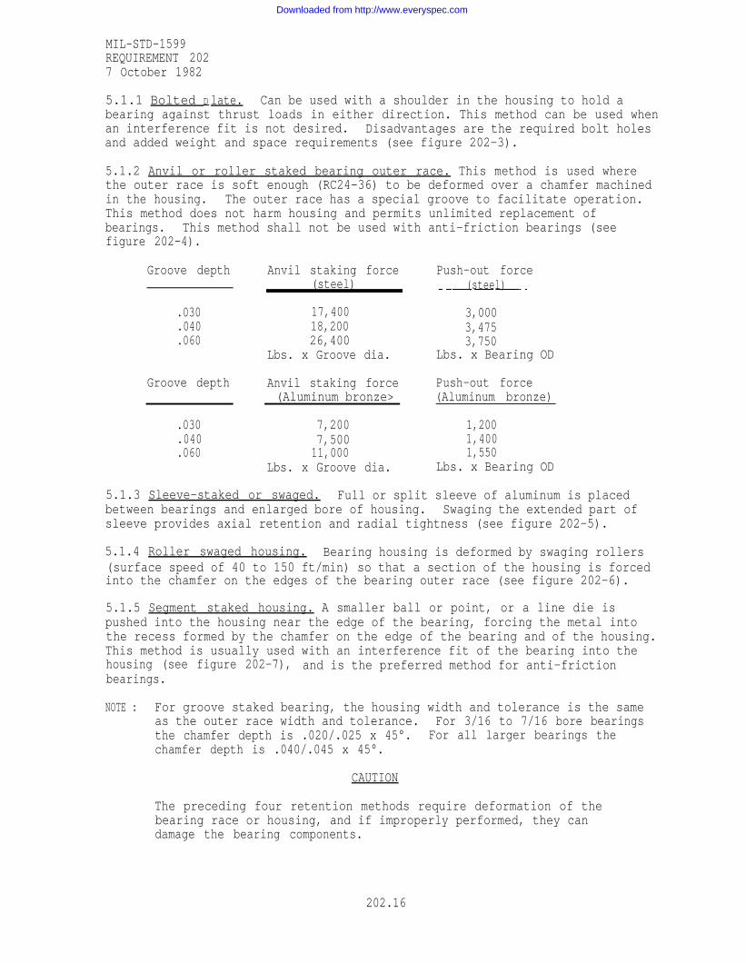
5.1.1 Bolted D late. Can be used with a shoulder in the housing to hold abearing against thrust loads in either direction. This method can be used whenan interference fit is not desired. Disadvantages are the required bolt holesand added weight and space requirements (see figure 202-3).
5.1.2 Anvil or roller staked bearing outer race. This method is used wherethe outer race is soft enough (RC24-36) to be deformed over a chamfer machinedin the housing. The outer race has a special groove to facilitate operation.This method does not harm housing and permits unlimited replacement ofbearings. This method shall not be used with anti-friction bearings (seefigure 202-4).
Groove depth Anvil staking force Push-out force(steel) (steel)
.030 17,400 3,000
.040 18,200 3,475
.060 26,400 3,750Lbs. x Groove dia. Lbs. x Bearing OD
Groove depth Anvil staking force Push-out force(Aluminum bronze> (Aluminum bronze)
.030 7,200 1,200
.040 7,500 1,400
.060 11,000 1,550Lbs. x Groove dia. Lbs. x Bearing OD
5.1.3 Sleeve-staked or swaged. Full or split sleeve of aluminum is placedbetween bearings and enlarged bore of housing. Swaging the extended part ofsleeve provides axial retention and radial tightness (see figure 202-5).
5.1.4 Roller swaged housing. Bearing housing is deformed by swaging rollers(surface speed of 40 to 150 ft/min) so that a section of the housing is forcedinto the chamfer on the edges of the bearing outer race (see figure 202-6).
5.1.5 Segment staked housing. A smaller ball or point, or a line die ispushed into the housing near the edge of the bearing, forcing the metal intothe recess formed by the chamfer on the edge of the bearing and of the housing.This method is usually used with an interference fit of the bearing into thehousing (see figure 202-7), and is the preferred method for anti-frictionbearings.
NOTE : For groove staked bearing, the housing width and tolerance is the sameas the outer race width and tolerance. For 3/16 to 7/16 bore bearingsthe chamfer depth is .020/.025 x 45°. For all larger bearings thechamfer depth is .040/.045 x 45°.
CAUTION
The preceding four retention methods require deformation of thebearing race or housing, and if improperly performed, they candamage the bearing components.
202.16
Downloaded from http://www.everyspec.com

MIL-STD-1599REQUIREMENT 2027 October 1982
5.1.6 Adhesive bonding. The bearing may be placed against a shoulder in thehousing. This method requires a clearance between the bearing and housing toestablish a proper “bond line” thickness. Rigorous cleaning of the surface isessential. Several adhesive components are available. Anaerobic and epoxiesare the most commonly used. If heat cured epoxies are used with aluminumbearings or housings, care must be taken to assure that the temper of thealuminum is not affected.
5.1.7 Threaded ring. This retention technique requires a specially designedbearing with a flange at one race face to accommodate a threaded retention ring(see figure 202-8).
5.2 Proof testing. Most of the retention systems require metal deformation.If the staking is not done correctly, the retention capability may not beadequate. In cases where loss of retention strength may result in acatastrophic loss of a system, it may be desirable to perform a proof test onthe staked bearing assembly. Proof tests should be performed at the designload for the assembly. The load should be maintained long enough so that anyaxial movement between the bearing and its housing ceases. Axial movementgenerally is acceptable if kept within prescribed limits dictated by theapplication. This is the preferred method for anvil staked bearings. Thistechnique may also be required for arbor staked bearings in criticalapplications.
5.3 Staking inspection. When properly installed, bearings which have had theouter race roller staked over a housing chamfer shall exhibit the followingcharacteristics:
a. Any gap between the bearing’s staked lip and housing chamfer shall notexceed .005 inches (see figure 202-9).
b. The bearing's staked lips shall not exhibit cracks in the material. Thisincludes a crack through the staked lip, a partial crack not through the lip,or a circumferential crack on the staked lip (see figure 202-10).
It is recommended that an illuminated magnifying glass or other suitableequipment be used when inspecting for these characteristics.
c. The bearinq's staked lip shall not exhibit deeply scratched, gouged, orscore marks on the inner side or unstaked side of the bearing staking groove(see figure 202-11).
d. The bearing’s staked lip shall not be over-staked, that is, the staking lipshall not be feathered to a knife edge beyond the face of the housing (seefiqure 202-12).
e. Gouges, chips and dirt in the bearing's staked lip are not acceptable.Minor impressions or contaminants, such as dust, in the bearing's staked lipare acceptable.
202-17
Downloaded from http://www.everyspec.com

MIL-STD-1599REQUIREMENT 2027 October 1982
6. Bearing removal and replacement
6.1 When a bearing has been retained in its housing by any of the techniquesthat require bearing or sleeve staking, removal of the deformed metal will berequired before the bearing can be removed from the housing. This machiningoperation must be performed carefully so that excess material will not beremoved.
6.2 When a bearing is pushed out of the housing, it may score the I.D. Thedegree of scoring will be determined by the interference conditions which existand by the adequacy of removal of the staked metal.
6.3 In many instances, the scoring in the housing could result in fatigueproblems and cannot be tolerated.
6.4 In cases where a bearing is assembled into its housing with clearance, thescoring will, in all probability, be q inor and need only be removed by brushhoning or polishing. The material removed should not increase the housing borebeyond the original blueprint requirements. If the scoring cannot be removedwithout causing the bore to go out of the original tolerance, the bore must beremachined to a new size, and either a special bearing must be refabricated tofit the new bore, or a staking ring should be installed with the bearing.Plating or hard anodize can also be used to restore the housing dimension.When polishing or re-machining chamfered housings, care must be taken topreserve the sharp edge at the bottom of the chamfer. The retention strengthof the staked bearing is dependent upon these chamfers being sharp enough to“bite into" the staked bearing race. When an interrupted housing stake isused, it will be necessary to index the staking tool, so that during bearingreplacement only virgin housing material will be staked.
6.5 Individual company policy may require MRB approval of any housing rework.
202.18
Downloaded from http://www.everyspec.com

MIL-STD-1599REQUIREMENT 2027 October 1982
Table 202-X. Advantages of various bearing retention methods.
Figure 202-3. Bolted plate.
202.19
Downloaded from http://www.everyspec.com

MIL-STD-1599REQUIREMENT 2027 October 1982
Figure 202-4. Anvil or roller staked bearing outer race.
202.20
Downloaded from http://www.everyspec.com

Before Swaging
MIL-STD-1599REQUIREMENT 2027 October 1982
After Swaging
Figure 202-5. Sleeve staked or swaged.
NOTE : Both sides may also be roller stakedFigure 202-6. Roller swaged housing.
202.21
Downloaded from http://www.everyspec.com

MIL-STD-1599REQUIREMENT 2027 October 1982
Figure 202-7. Segment staked housing.
202.22
Downloaded from http://www.everyspec.com

MIL-STD-1599REQUIREMENT 2027 October 1982
Threaded Race Bearing
NOTE: The flange and nut configurations are optional and need not be as shown.
Figure 202-8. Threaded rinq.
202.23
Downloaded from http://www.everyspec.com

MIL-STD-1599REQUIREMENT 2027 October 1982
Figure 202-9. Gap between staked lip and housing chamfer.
Figure 202-11.
Figure 202-10. Cracks in staked lips.
Scratched. gouged or score marks on staking groove.
Figure 202-12. Over-staking.
202.24
Downloaded from http://www.everyspec.com

MIL-STD-1599REQUIREMENT 3017 October 1982
AIRFRAME BEARINGS, BALL, ANTI-FRICTION
1. Scope
1.1 This requirement establishes engineering criteria and requirements for theselection and application of rolling element anti-friction ball bearings foraerospace systems.
1.2are
a.b.c.d.e.f.g.h.
2.
Classification. Anti-friction ball bearings covered by this requirementof the following classes:
Extra light dutyIntermediate dutyHeavy dutyDouble rowDouble row, self-aligningExtra wideSingle rowSingle row, self-aligning
Documents applicable to requirement 301
MIL-B-7949MS21428
MS27640MS27641
MS27642MS27643
MS27644MS27645
MS27646MS27647
MS27648
Bearing, Ball, Airframe,Bearing, Ball, Airframe,PrecisionBearing, Ball, Airframe,Bearing, Ball, Airframe,DutyBearing, Ball, Airframe,Bearing, Ball, Airframe,Row, Heavy DutyBearing, Ball, Airframe,Bearing, Ball, Airframe,Heavy DutyBearing, Ball, Airframe,Bearing, Ball, Airframe,Intermediate DutyBearing, Ball, Airframe,
Anti-FrictionAnti-Friction, Extra Light Duty
Anti-Friction, Heavy DutyAnti-Friction, Heavy Duty, Intermediate
Extra Light DutyAnti-Friction, Self-Aligning, Double
Anti-Friction, Double Row, Heavy DutyAnti-Friction, Self-Aligning, Light and
Anti-Friction, Extra Light DutyAnti-Friction, Extra Wide, Double Row,
Anti-Friction, ExternallySelf-Aligning, Extra Light Duty
MS27649 Bearing, Ball, Airframe, Anti-Friction, Intermediate Duty
3. General. Anti-friction ball bearings are used throughout airframe systemsin many different types of applications and environmental conditions. Forselection and usage guidelines, see requirement 201. For shaft, housing, andinstallation, see requirement 202.
4. Requirement
4.1 Qualification. Anti-friction ball bearings defined under this requirementshall be products which are qualified for listing on the applicable qualifiedproducts list of MIL-B-7949.
301.1
Downloaded from http://www.everyspec.com

MIL-STD-1599REQUIREMENT 3017 October 1982
4.2 Desire and construction. These bearings conform to the requirements ofMIL-B-7949, MS21428, MS27640, MS27641, MS27642, MS27643, MS27644, MS27645,MS27646, MS27647, MS27648, and MS27649.
4.3 Performance
4.3.1. Radial limit load rating. These bearings have a minimum limit loadrating as specified on the applicable MS.
4.3.2 Radial fracture load. The minimum static fracture load is not less than1 1/2 times the radial limit load value specified on the applicable MS.
4.3.3 Axial limit load rating. These bearings have a minimum limit loadrating as specified on the applicable MS.
4.3.4 Axial fracture load. The minimum axial fracture load is not less than1 1/2 times the axial limit load values specified on the applicable MS.
4.3.5 Radial dynamic load rating
4.3.5.1 These bearings have a radial dynamic load rating, at 250°F, asspecified on the applicable MS for an average life of 10,000 cycles whenoscillated through an arc of 90°F.
4.3.5.2 These bearings have a radial dynamic load rating, at 350°F, of notless than 80 percent of the value specified on the applicable MS for an averagelife of 10,000 cycles when oscillated through an arc of 90°F.
301.2
Downloaded from http://www.everyspec.com

MIL-STD-1599REQUIREMENT 3027 October 1982
AIRFRAME BEARINGS, ANTI-FRICTION ROLLER
1. Scope. This requirement establishes engineering criteria and requirementsfor the selection and application of self-aligning, anti-friction sealed,airframe roller bearings for aerospace systems.
2. Documents applicable to requirement 302.
MIL-B-8914 Bearings, Roller, Self-Aligning Airframe, Anti-FrictionMS28912 Bearings, Roller, Self-Aligning, Single Row, Airframe,
Anti-Friction, Sealed, Type IMS28913 Bearings, Roller, Self-Aligning, Double Row, Airframe,
Anti-Friction, Sealed, Type IIMS28914 Bearings, Roller, Self-Aligning, Double Row, Wide Inner Ring,
Airframe, Anti-Friction, Sealed, Type IIIMS28915 Bearings, Roller, Self-Aligning, Double Row, Torque Tube,
Airframe, Anti-Friction, Sealed, Type IVMS21431 Bearings, Roller, Self-Aligning, Single Row, Anti-Friction,
Sealed, -65°F - 350°F, Type I
3. General. Typical airframe roller bearings utilize a compliment of rollersseparating an outer ring and an inner ring. The outer ring is usually mountedin the housing and the inner ring on the shaft. Other elements of thesebearings may be rolling element separators, shields or seals, and sealretainers.
3.1 Usage. Guidelines on selection are contained in requirement 201.
4. Design requirements. Design and construction of these bearings shallconform to the requirements of MIL-F-8914, MS28912, MS28913, MS28914, MS28915,and MS21431.
5. Performance requirements. Engineering criteria on friction, torque,temperature capabilities, and rotational and alignment capabilities arecontained in requirement 201.
6. Installation and retention. Guidelines on installation and retention arecontained in requirement 201 and requirement 202.
302.1
Downloaded from http://www.everyspec.com

Downloaded from http://www.everyspec.com

MIL-STD-1599REQUIREMENT 3087 October 1982
ROD ENDS
1. Scope
1.1 This requirement defines plain, spherical, self-lubricating rod ends,roller bearing rod ends, and ball bearing rod ends for aerospace systems.
1.2 Classifications. Rod ends shall be classified as follows:
a. Type I - Plain spherical self-lubricating rod endsb. Type II - Roller bearing rod endsc. Type III - Ball bearing rod endsd. Class 1 - Externally threadede. Class 2 - Internally threadedf. Class 3 - Solid shankg. Class 4 - Hollow shankh. Composition A - Fabric bearing liner of uniform thickness which is bonded
to the inside diameter of the outer racei. Composition B - Molded composition liner system
2. Documents applicable to requirement 308.
MIL-B-6039
MIL-B-8952MIL-B-81935M81935/1
M81935/2
MS14103
MS21150
MS21151
MS21152
MS21153
MS21220
MS21221
MS21223
MS21429
Bearing, Double Row, Ball, Sealed Rod End, Anti-Friction,Self-AligningBearing, Roller, Rod End, Anti-Friction, Self-AligningBearing, Plain, Rod End, Self-Aligning, Self-LubricatingBearing, Plain, Rod End, Self-Aligning, Self-Lubricating,Externally Threaded, -65°F to +325°FBearing, Plain, Rod End, Self-Aligning, Self-Lubricating,Internally Threaded, -65°F to +325°FBearings, Plain, Self-Lubricating, Self-Aligning, Low Speed,Wide, Grooved Outer Ring, -65°F to 325°FBearing, Double Row, Ball, Rod End, Precision, Solid Shank,Self-Aligning, Anti-Friction, Airframe, Type I, -65°F to +350°FBearing, Double Row, Ball, Rod End, Precision, External Thread,Self-Aligning, Anti-Friction, Airframe, -65°F to +350°FBearing, Double Row, Ball, Rod End, Precision, Hollow Shank,Self-Aligning, Anti-Friction, Airframe, Type III, -65°F to+350°FBearing, Ball, Rod End, Precision, Internal Thread,Self-Aligning, Anti-Friction, Airframe, Type IV, -65°F to +350°FBearing, Roller, Rod End, Internal Thread, Self-Aligning,Anti-Friction, Airframe, Heavy Duty, Type II, -67°F to +350°F,SealedBearing, Roller, Rod End, External Thread, Self-Aligning,Anti-Friction, Airframe, Heavy Duty, Type I, -67°F to +350°F,SealedBearing, Roller, Rod End, External Thread, Self-Aligning,Anti-Friction, Airframe, Heavy Duty, Type II, -67°F to +350°F,SealedBearing, Roller, Rod End, External Thread, Self-Aligning,Anti-Friction, Airframe, Heavy Duty, Type I, -67°F to +350°F,Sealed
308.1
Downloaded from http://www.everyspec.com

MIL-STD-1599REQUIREMENT 3087 October 1982
3. Intended use. Types I, II, and III rod ends are for use in aerospacesystems in many different applications and environments.
4. Requirements
4.1 Qua lifications
4.1.1 Type I, class 1 and class 2, composition A and composition B rod endsare products that conform to the requirements of MIL-B-81935.
4.1.2 Type II, class 1 and class 2 rod ends are products that conform to therequirements of MIL-B-8952.
4.1.3 Type III, class 1, class 2, class 3, and class 4 rod ends are productsthat conform to the requirements of MIL-B-6039.
4.2 Desire and construction
4.2.1 Type I, class 1 and class 2, composition A and composition B rod endsare products that conform to the requirements of MIL-B-81935, M81935/1,M81935/2, and MS14103.
4.2.2 Type II, class 1 and class 2 rod ends are products that conform to therequirements of MIL-B-8952, MS21220, MS21221, MS21223, and MS21429.
4.2.3 Type III, class 1, class 2, class 3, and class 4 rod ends are productsthat conform to the requirements of MIL-B-6039, MS21150, MS21151, MS21152, andMS21153.
4.3 Performance
4.3.1 Load ratings for type I, class 1 and class 2, composition A andcomposition B rod ends
4.3.1.1 Static radial ultimate load. Static radial ultimate load is definedin MIL-B-81935. After application of this load, there may be significantpermanent deformation of the rod end and bearing cartridge components.However, application of the ultimate loads specified on M81935/1 and M81935/2shall not result in cracked or broken components.
4.3.1.2 Axial static proof load. There shall be no pushout of the bearingcartridge when the axial proof loads specified on M81935/1 and M81935/2 areapplied.
4.3.1.3 Fatigue load. Rod ends covered by MIL-B-81935 are capable ofwithstanding a minimum of 50,000 cycles of the fatigue loads specified onM81935/1 and M81935/2 when applied at a rate not exceeding 2800 cycles perminute.
4.3.2 Load ratings for type II, class 1 and class 2 rod ends
4.3.2.1 Limit load rating. Limit load rating is defined as the maximum staticload that can be applied to the bearing without seriously affecting thepredicted life. These loads are specified on Ms21220, MS21221, MS21223, andMS21429.
308.2
Downloaded from http://www.everyspec.com
MIL-STD-1599REQUIREMENT 3087 October 1982
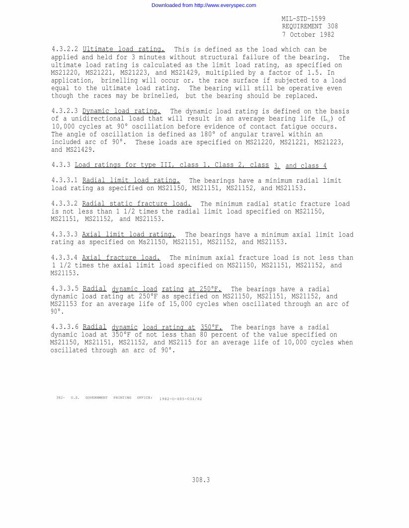
4.3.2.2 Ultimate load rating. This is defined as the load which can beapplied and held for 3 minutes without structural failure of the bearing. Theultimate load rating is calculated as the limit load rating, as specified onMS21220, MS21221, MS21223, and MS21429, multiplied by a factor of 1.5. Inapplication, brinelling will occur or. the race surface if subjected to a loadequal to the ultimate load rating. The bearing will still be operative eventhough the races may be brinelled, but the bearing should be replaced.
4.3.2.3 Dynamic load rating. The dynamic load rating is defined on the basisof a unidirectional load that will result in an average bearing life (L50) of10,000 cycles at 90° oscillation before evidence of contact fatigue occurs.The angle of oscillation is defined as 180° of angular travel within anincluded arc of 90°. These loads are specified on MS21220, MS21221, MS21223,and MS21429.
4.3.3 Load ratings for type III, class 1. Class 2, class 3, and class 4
4.3.3.1 Radial limit load rating. The bearings have a minimum radial limitload rating as specified on MS21150, MS21151, MS21152, and MS21153.
4.3.3.2 Radial static fracture load. The minimum radial static fracture loadis not less than 1 1/2 times the radial limit load specified on MS21150,MS21151, MS21152, and MS21153.
4.3.3.3 Axial limit load rating. The bearings have a minimum axial limit loadrating as specified on Ms21150, MS21151, MS21152, and MS21153.
4.3.3.4 Axial fracture load. The minimum axial fracture load is not less than1 1/2 times the axial limit load specified on MS21150, MS21151, MS21152, andMS21153.
4.3.3.5 Radial dynamic load rating at 250°F. The bearings have a radialdynamic load rating at 250°F as specified on MS21150, MS21151, MS21152, andMS21153 for an average life of 15,000 cycles when oscillated through an arc of90°.
4.3.3.6 Radial dynamic load rating at 350°F. The bearings have a radialdynamic load at 350°F of not less than 80 percent of the value specified onMS21150, MS21151, MS21152, and MS2115 for an average life of 10,000 cycles whenoscillated through an arc of 90°.
382- U.S. GOVERNMENT PRINTING OFFICE: 1982-O-605-034/82
308.3
Downloaded from http://www.everyspec.com

Downloaded from http://www.everyspec.com