Embed Size (px)
Citation preview

Military, security andaerospace COTS
connector solutions
2
LEMO M Series
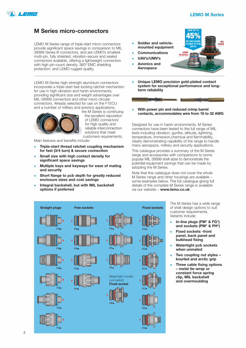
M Series micro-connectors
LEMO M Series range of triple-start micro-connectorsprovide significant space savings in comparison to MIL38999 Series III connectors, and are LEMO’s smallest multi-pin, fully shielded, vibration-secure and sealedconnectors available, offering a lightweight connectionwith high pin-count density, 360º EMC shieldingprotection, and LEMO rugged quality.
LEMO M-Series high-strength aluminium connectorsincorporate a triple-start fast-locking ratchet mechanismfor use in high vibration and harsh environments,providing significant size and weight advantages overMIL-38999 connectors and other micro circularconnectors. Already selected for use on the F1ECU and a number of military and avionics applications,
the M Series is continuingthe excellent reputationof LEMO connectors’for high quality andreliable interconnectionsolutions that meet
customers requirements.Main features and benefits include:
• Triple-start thread ratchet coupling mechanismfor fast (3/4 turn) & secure connection
• Small size with high contact density forsignificant space savings
• Multiple keys and keyways for ease of matingand security
• Short flange to pcb depth for greatly reducedenclosure sizes and cost savings
• Integral backshell, but with MIL backshelloptions if preferred
The M Series has a wide rangeof shell design options to suitcustomer requirements.Variants include:
• In-line plugs (FM* & FG*)and sockets (PM* & PH*)
• Fixed sockets -frontpanel, back panel andbulkhead fixing
• Watertight pcb socketswhen unmated
• Two coupling nut styles –knurled and arctic grip
• Three cable fixing options– metal tie-wrap orconstant force springclip, MIL backshell and overmoulding
• Unique LEMO precision gold-plated contactsystem for exceptional performance and long-term reliability
• With power pin and reduced crimp barrelcontacts, accommodates wire from 16 to 32 AWG
Designed for use in harsh environments, M Seriesconnectors have been tested to the full range of MILtests including vibration, gunfire, altitude, lightning,temperature, immersion,chemical and flammability,clearly demonstrating capability of the range to handlemany aerospace, military and security applications.
This catalogue provides a summary of the M Seriesrange and accessories with comparisons to somepopular MIL 38999 shell sizes to demonstrate the potential equipment savings that can be made byadopting the M Series.
Note that this catalogue does not cover the whole M Series range and other housings are available – some examples below. The full catalogue giving fulldetails of the complete M Series range is availablevia our website – www.lemo.co.uk
MIL38999
LEMOM-Series
SAVE UP TO
45%ON ENCLOSUREFLANGE TO PCB
DEPTH• Soldier and vehicle-
mounted equipment
• Communications
• UAV’s/UMV’s
• Avionics and Aerospace

3
LEMO M Series
Examples of COTS alternatives
Possible COTS alternatives to popular MIL 38999 shellconfigurations selected from the M Series range belowgive an idea of the scope for significant space reductionswhilst still meeting rating requirements for your
For reduced barrel contacts change the 14th characterof the LEMO part number from “C” to “B” for malecontacts and from “M” to “P” for female contacts.
application. These are some examples only and manyother housings and contact configurations are available – see our full LEMO M Series catalogue forfurther information.
MIL 38999 Shell size 9-98 9-35 11-98 11-35
LEMO COTS alternative Description 0M.303 1M.308 2M.308 2M.319No of contacts No 3 8 8 19Wire sizes AWG 20-22-24 22 -24- 26* 20-22-24 22 -24- 26*Contact rating Amps 8A 5A 10A 4APlug nominal dia mm 13.1 14.6 17.6 17.6
Heatshrink boot
No of contacts 3 6 6 13
Contact size 20 22 20 22
Nominal dia mm 21.8 21.8 24.6 24.6
FGN.0M.303.XLC FGN.1M.308.XLC FGN.2M.308.XLC FGN.2M.319.XLCStraight plug withintegral backshell,crimp contacts
UKT.0001272 UKT.0001272 UKT.0001273 UKT.0001273Straight boot
LEMO CABLE
7-2-3C 7-2-8C 16-2-8C 7-2-20C
Cable to DEF STAN 61-12,braided screen, or DIN,VDE, UL or proprietarycable as requested
For cable end to take overmoulding add "T" to end of part number
e.g. e.g. e.g. e.g.FGN.0M.303.XLCT FGN.1M.308.XLCT FGN.2M.308.XLCT FGN.2M.319.XLCTPHN.0M.303.XLMT PHN.1M.308.XLMT PHN.2M.308.XLMT PHN.2M.319.XLMT
Optional back endfor overmoulding
To add an optional MIL backshell fitting, add 'M' to the end of the part number
e.g. e.g. e.g. e.g.FGN.0M.303.XLCM FGN.1M.308.XLCM FGN.2M.308.XLCM FGN.2M.319.XLCMPHN.0M.303.XLMM PHN.1M.308.XLMM PHN.2M.308.XLMM PHN.2M.319.XLMM
**Optional back endfor fitting backshell
Backshell Thread size N/A M12x1 M15x1 M15x1
N/A UKT.B1.M12.04.1ZN UKT.B1.M15.06.1ZN UKT.B1.M15.08.1ZNshell too small
**Straight backshell option
N/A UKT.B3.M12.04.1ZN UKT.B3.M15.06.1ZN UKT.B3.M15.08.1ZN**90º backshell option
UKT.0001277 UKT.0001277 UKT.0001278 UKT.0001278Right angled boot
PEN.0M.303.XLMT PEN.1M.308.XLMT PEN.2M.308.XLMT PEN.2M.319.XLMTBulkhead socket withintegral backshell,crimp contacts
HEN.0M.303.XLNP HEN.1M.308.XLNP HEN.2M.308.XLNP HEN.2M.319.XLNPFixed socket, watertightwhen unmated,pcb contacts
PHN.0M.303.XLM PHN.1M.308.XLM PHN.2M.308.XLM PHN.2M.319.XLMIn-line socket with integralbackshell, crimp contacts
LEMO M Series a few examples with part numbers of COTS equivalent options
* Reduced barrel contacts available for smaller wire gauges down to 32AWG.** Note standard M Series has integral backshell.
Standard contacts Reduced barrel contacts

4
LEMO M Series
Examples of COTS alternatives
A few more possible COTS alternatives to popular MIL38999 configurations are given below.
For reduced barrel contacts change the 14th characterof the LEMO part number from “C” to “B” for malecontacts and from “M” to “P” for female contacts.
MIL 38999 Shell size 13-4 13-35 15-35 17-35
LEMO COTS alternative Description 2M.304 3M.330 TM.340 LM.368No of contacts No. 4 30 40 68Wire sizes AWG 16-18-20 22-24-26* 22-24-26* 22-24-26*Contact rating Amps 12.0 3.5 3.0 2.5Plug nominal dia mm 17.6 20.9 23.4 29.4
Heatshrink boot
No of contacts 4 22 37 55
Contact size 16 22 22 22
Nominal dia mm 29 29 32 35
FGN.2M.304.XLC FGN.3M.330.XLC FGN.TM.340.XLC FGN.LM.368.XLCStraight plug withintegral backshell,crimp contacts
UKT.0001273 UKT.0001274 UKT.0001274 UKT.0001275Straight boot
LEMO CABLE
16-2-4C 7-2-36C On request On request
Cable to DEF STAN 61-12,braided screen, or DIN,VDE, UL or proprietarycable as requested
For cable end to take overmoulding add "T" to end of part number
e.g. e.g. e.g. e.g.FGN.2M.304.XLCT FGN.3M.330.XLCT FGN.TM.340.XLCT FGN.LM.368.XLCTPHN.2M.304.XLMT PHN.3M.330.XLMT PHN.TM.340.XLMT PHN.LM.368.XLMT
Optional back endfor overmoulding
To add an optional MIL backshell fitting, add 'M' to the end of the part number
e.g. e.g. e.g. e.g.FGN.2M.304.XLCM FGN.3M.330.XLCM FGN.TM.340.XLCM FGN.LM.368.XLCMPHN.2M.304.XLMM PHN.3M.330.XLMM PHN.TM.340.XLMM PHN.LM.368.XLMM
**Optional back endfor fitting backshell
Backshell Thread size M15x1 M18x1 M18x1 M25x1
UKT.B1.M15.04.1ZN UKT.B1.M18.07.1ZN UKT.B1.M18.08.1ZN UKT.B1.M18.10.1ZN**Straight backshell option
UKT.B3.M15.04.1ZN UKT.B3.M18.07.1ZN UKT.B3.M18.08.1ZN UKT.B3.M18.10.1ZN**90º backshell option
UKT.0001278 UKT.0001279 UKT.0001279 UKT.0001280Right angled boot
PEN.2M.304.XLMT PEN.3M.330.XLCT PEN.TM.340.XLMT PEN.LM.368.XLMTBulkhead socket withintegral backshell,crimp contacts
HEN.2M.304.XLNP HEN.3M.330.XLNP HEN.TM.340.XLNP HEN.LM.368.XLNPFixed socket, watertightwhen unmated,pcb contacts
PHN.2M.304.XLM PHN.3M.330.XLM PHN.TM.340.XLM PHN.LM.368.XLMIn-line socket with integralbackshell, crimp contacts
LEMO M Series a few examples with part numbers of COTS equivalent options
* Reduced barrel contacts available for smaller wire gauges down to 32AWG.** Note standard M Series has integral backshell.
Standard contacts Reduced barrel contacts

5
Ref
eren
ce
305
307
308
1M
304
308
310
312
319
2M
322
330
3M
302
303
304
305
0M
ø A
Male crimp contactsfor plug
Female crimp contactsfor sockets N
umb
er o
f co
ntac
ts
Con
tact
dia
. m
m
AW
G
Rat
ed c
urre
nt
Cod
e fo
r p
ositi
oner
22 0.7 22-24-26 5.0 2
30 0.7 22-24-26 3.5 2
5 0.9 20-22-24 9.0 1
7 0.7 22-24-26 7.00 2
8 0.7 22-24-26 5.00 2
4 1.3 16-18-20 12.0 5
8 0.9 20-22-24 10.0 1
10 0.9 20-22-24 8.0 1
12 0.7 22-24-26 7.0 2
19 0.7 22-24-26 4.0 2
2 0.9 20-22-24 10.0 1
3 0.9 20-22-24 8.0 1
4 0.7 22-24-26 7.0 2
5 0.7 22-24-26 6.5 2
14
23
1 4
2 3
325
340
TM25 0.9 20-22-24 5.0 3
40 0.7 22-24-26 3.0 4
340
348
4M40 0.7 22-24-26 3.5 4
48 0.7 22-24-26 tbd 4
355
368
LM55 0.9 20-22-24 tbd 3
68 0.7 22-24-26 2.5 4
366
114
5M66 0.9 20-22-24 tbd 3
114 0.7 22-24-26 2.0 4
Positioners forcrimp contacts
DCE
male female
LEMO M Series
Contact configurations
Part Number
DCF.93.070.4LT
DCF.93.090.4LT
DCF.93.131.4LT
Contact diameter (mm)
0.7
0.9
1.3
Contact extraction tools
Part Number
DPC.91.701.V
DPC Manual crimping tool
For male contacts
DCE.91.090.5MVC
DCE.91.070.5MVC
DCE.91.090.5MVC
DCE.91.070.5MVC
DCE.91.130.5MVG
For female contacts
DCE.91.090.3MVM
DCE.91.070.3MVM
DCE.91.09T.5MVM
DCE.91.07T.5MVM
DCE.91.130.5MVU
Code
1
2
3
4
5
Positioners part number
The previous pages contain a selectionof insert types to give an idea of howthe M Series compares with MIL 38999Series III configurations. However amuch wider range of contactconfigurations is offered which isgrowing all the time. If you do not seewhat you are looking for please contactLEMO to see if the configuration yourequire is available. All contacts otherthan for pcb are crimp contacts forwhich you will need a standard style701 crimp tool and LEMO positioner.Use the positioner code in the tableopposite to select the relevantpositioner below.
Crimping tool to MIL-C-22520/7-01 foruse with positioners above.

6
plated brass caps for marine applications change the“X” to “C”.
Straight and right-angled boots suitablefor a range of connectors. They aremanufactured from highquality elastomer suitablefor a wide rangeof temperatures (-75ºC to +150ºC)and environmentswith excellent resistance to fuels in particular.
Adhesive-lined with a high-temperature (-75ºC to+200ºC) capability epoxy adhesive also with excellentresistance to fuels and oils, this range of heat-shrinkboots complements the excellent performance of MSeries connectors in demanding applications.
Accessories
BGF
To select the correct cap choose a part number withthe same size/series as the connector. For chrome-
Blanking caps
Heatshrink boots
A range of high quality cables is stocked at LEMO UK,including to DIN, VDE and UL specifications, with theDEF STAN 61-12 range being offered as standard foruse with the M Series.
Some examples are shown in the tables on pages 3 &4, and options are available to match the full range ofinserts shown on page 5. A full cable assemblyservice is also available from LEMO UK – see page 8.
Cable
Part Number
BGF.0M.100.XAV
BGF.1M.100.XAV
BGF.2M.100.XAV
BGF.3M.100.XAV
BGF.TM.100.XAV
BGF.4M.100.XAV
BGF.LM.100.XAV
BGF.5M.100.XAV
Blanking caps for plugs
BGEPart Number
BGE.0M.200.XAZ
BGE.1M.200.XAZ
BGE.2M.200.XAZ
BGE.3M.200.XAZ
BGE.TM.200.XAZ
BGE.4M.200.XAZ
BGE.LM.200.XAZ
BGE.5M.200.XAZ
Blanking caps for fixed sockets
BGFPart Number
BGF.0M.200.XAZ
BGF.1M.200.XAZ
BGF.2M.200.XAZ
BGF.3M.200.XAZ
BGF.TM.200.XAZ
BGF.4M.200.XAZ
BGF.LM.200.XAZ
BGF.5M.200.XAZ
Blanking caps for in-line sockets
165° 30°
150° 60°
130° 100°
155° 50°
135° 90°
Angles
β γ
••N
••P
••U
••S
••T
Contact type
Plug Socket
male female
female maleγ
β
blue
yellow
green
red
orange
Colourcode
3
Nb of keys
Angles
α β γ δ
••W
••R
••X
••V
95° 115° 35° 25°
105° 115° 30° 20°
100° 125° 40° 20°
110° 120° 35° 25°
Contact type
Plug Socket
male female
female male
Mod
elM
odel
γ
β
δ
α
blue
yellow
red
orange
Colourcode
5
Nb of keys
Front view of a socket
Front view of a socket
0M t
o 3
MT
M t
o 5
M
Up to 5 keying options are available, some withreverse gender contacts. “N” key is the standard forsizes 0M to 3M, and “W” key is the standard for the
remaining sizes. Change the 3rd character of theLEMO part number to select your required key as perthe table below.
Keying options
90° no lip,
epoxy adhesive
UKT.0001277
UKT.0001277
UKT.0001278
UKT.0001279
UKT.0001279
UKT.0001280
UKT.0001280
UKT.0001281
Series
0M
1M
2M
3M
TM
4M
LM
5M
Straight no lip,
epoxy adhesive
UKT.0001272
UKT.0001272
UKT.0001273
UKT.0001274
UKT.0001274
UKT.0001275
UKT.0001275
UKT.0001276
Min
cable OD
3.8
3.8
5.6
6.6
6.6
7.1
7.1
8.4
Min
cable OD
2.5
2.5
5.6
6.3
6.3
7.1
7.1
8.4
Cable can be made up to suit customer requirements.
7
Front conical nut tightening tools
Accessories
Backshells
M Series
1M
2M
3M
TM
4M
LM
5M
Thread size
M12x1.0
M15x1.0
M18x1.0
M18x1.0
M22x1.0
M25x1.0
M31x1.0
Interface thread sizes
Cable entrynominal size
03
04
05
06
07
08
10
12
14
16
18
Max entry (mm)
4.7
6.3
7.9
9.5
11.1
12.7
15.8
19.0
22.2
25.4
28.6
Cable entry sizes
Part number example
UKT.B
1
M12
04
1
ZN
S
UKT.B1.M12.04.1ZN
1 = straight, 2 = 45º, 3 = 90º
Interface thread size - see table
Cable entry size - see table
Material (aluminium as standard)
Plating (eg. zinc nickel black)
Add “S” if slots required foradditional drain wire termination,
else leave blank
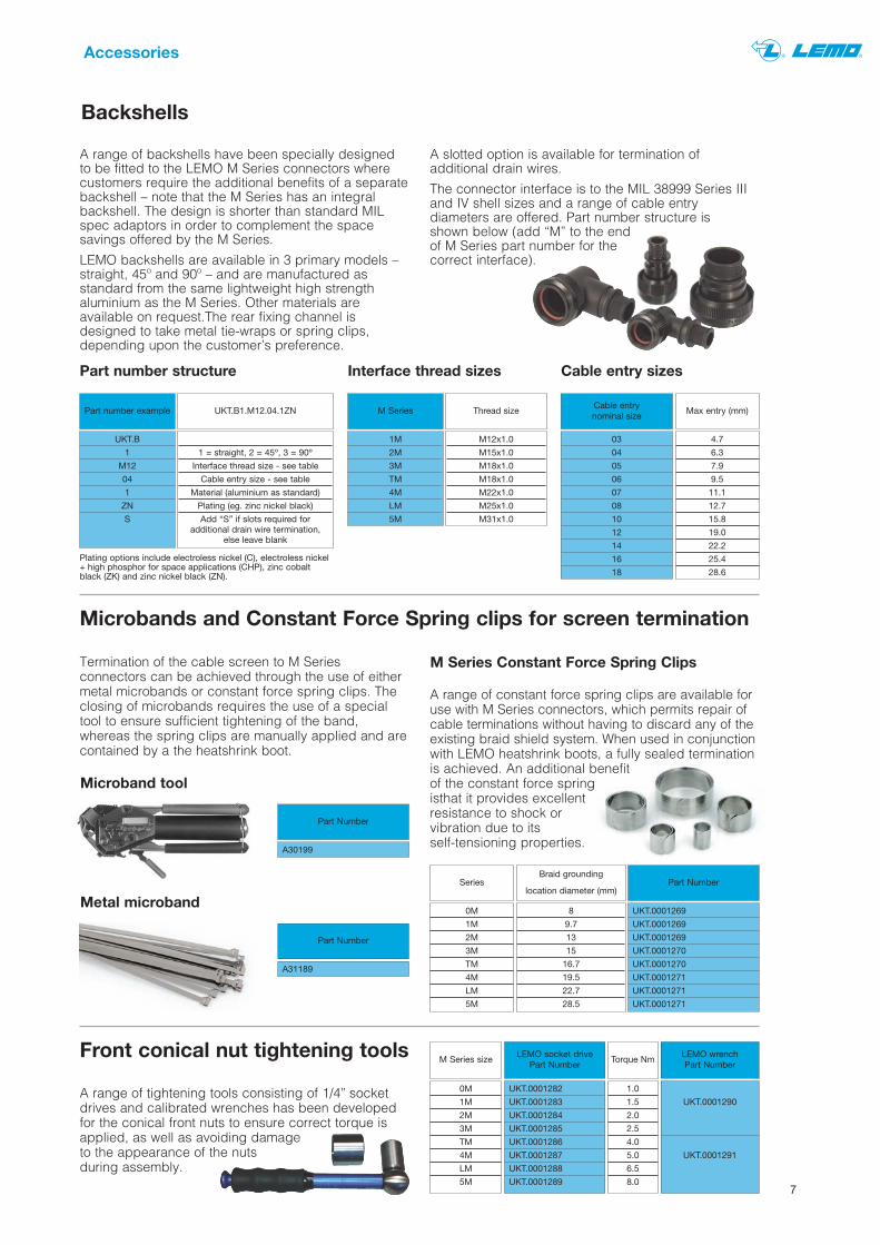
Part number structure
Plating options include electroless nickel (C), electroless nickel+ high phosphor for space applications (CHP), zinc cobaltblack (ZK) and zinc nickel black (ZN).
A range of backshells have been specially designedto be fitted to the LEMO M Series connectors wherecustomers require the additional benefits of a separatebackshell – note that the M Series has an integralbackshell. The design is shorter than standard MILspec adaptors in order to complement the spacesavings offered by the M Series.
LEMO backshells are available in 3 primary models –straight, 45º and 90º – and are manufactured asstandard from the same lightweight high strengthaluminium as the M Series. Other materials areavailable on request.The rear fixing channel isdesigned to take metal tie-wraps or spring clips,depending upon the customer’s preference.
Microbands and Constant Force Spring clips for screen termination
Termination of the cable screen to M Seriesconnectors can be achieved through the use of eithermetal microbands or constant force spring clips. Theclosing of microbands requires the use of a specialtool to ensure sufficient tightening of the band,whereas the spring clips are manually applied and arecontained by a the heatshrink boot.
A range of tightening tools consisting of 1/4” socketdrives and calibrated wrenches has been developedfor the conical front nuts to ensure correct torque isapplied, as well as avoiding damageto the appearance of the nutsduring assembly.
A slotted option is available for termination ofadditional drain wires.
The connector interface is to the MIL 38999 Series IIIand IV shell sizes and a range of cable entrydiameters are offered. Part number structure is shown below (add “M” to the endof M Series part number for thecorrect interface).
Part Number
UKT.0001269
UKT.0001269
UKT.0001269
UKT.0001270
UKT.0001270
UKT.0001271
UKT.0001271
UKT.0001271
Series
0M
1M
2M
3M
TM
4M
LM
5M
Braid grounding
location diameter (mm)
8
9.7
13
15
16.7
19.5
22.7
28.5
M Series Constant Force Spring Clips
LEMO wrench Part Number
UKT.0001290
UKT.0001291
M Series size
0M
1M
2M
3M
TM
4M
LM
5M
LEMO socket drivePart Number
UKT.0001282
UKT.0001283
UKT.0001284
UKT.0001285
UKT.0001286
UKT.0001287
UKT.0001288
UKT.0001289
Part Number
A30199
Microband tool
Part Number
A31189
Metal microband
A range of constant force spring clips are available foruse with M Series connectors, which permits repair ofcable terminations without having to discard any of theexisting braid shield system. When used in conjunctionwith LEMO heatshrink boots, a fully sealed terminationis achieved. An additional benefitof the constant force springisthat it provides excellentresistance to shock orvibration due to its self-tensioning properties.
Torque Nm
1.0
1.5
2.0
2.5
4.0
5.0
6.5
8.0
March 2013
Please contact [email protected] or phone 01903 234543 for further information.
LEMO Worldwide
AUSTRIALEMO Elektronik GesmbHTel: (+43 1) 914 23 20 0
CHINALEMO Trading (Shanghai) Co., Ltd.Tel: (+86 21) 58 99 77 21
DENMARKLEMO DENMARK A/STel: (+45) 45 20 44 00
FRANCELEMO FRANCE SàrlTel: (+33 1) 60 94 60 94
GERMANYLEMO Elektronik GmbHTel: (+49 89) 42 77 03
HONG KONGLEMO Hong Kong Ltd.Tel: (+852) 21 74 04 68
LEMO S.A.Chemin de Champs-Courbes 28P.O. Box 194, CH-1024 Ecublens, SwitzerlandTel (+41 21) 695 16 00 Fax (+41 21) 695 16 01 [email protected]
LEMO UK Ltd12 – 20 North Street, Worthing, West Sussex, BN11 1DU.Tel: (+44 1903) 23 45 43 Fax: (+44 1903) 20 62 31 [email protected]
HUNGARYREDEL Elektronika KftTel: (+36 1) 421 47 10
ITALYLEMO ITALIA srlTel: (+39 02) 66 71 10 46
JAPANLEMO JAPAN LtdTel: (+81 3) 53 44 39 33
NETHERLANDS/BELGIUM/LUXEMBURGLEMO Connectors BeneluxTel: (+31) 251 25 78 20
NORWAY/ICELANDLEMO NORWAY A/STel: (+47) 22 91 70 40
SPAIN/PORTUGALIBERLEMO S.A.Tel: (+34 93) 860 44 20
SINGAPORELEMO Asia Pte LtdTel: (+65) 6476 0672
SWEDEN/FINLANDLEMO Nordic ABTel: (+46 8) 635 60 60
SWITZERLANDLEMO VERKAUF AGTel: (+41 41) 790 49 40
USALEMO USA Inc.Tel: (+1 707) 578 88 11
(+1 800) 444 53 66
LEMO DistributorsAUSTRALIABRAZILCANADACZECH REPUBLICGREECEINDIAISRAELNEW ZEALANDPHILIPPINES?POLANDRUSSIA?SINGAPORE?SOUTH AFRICASOUTH KOREATAIWANTHAILANDTURKEYUKRAINE
www.lemo.co.uk
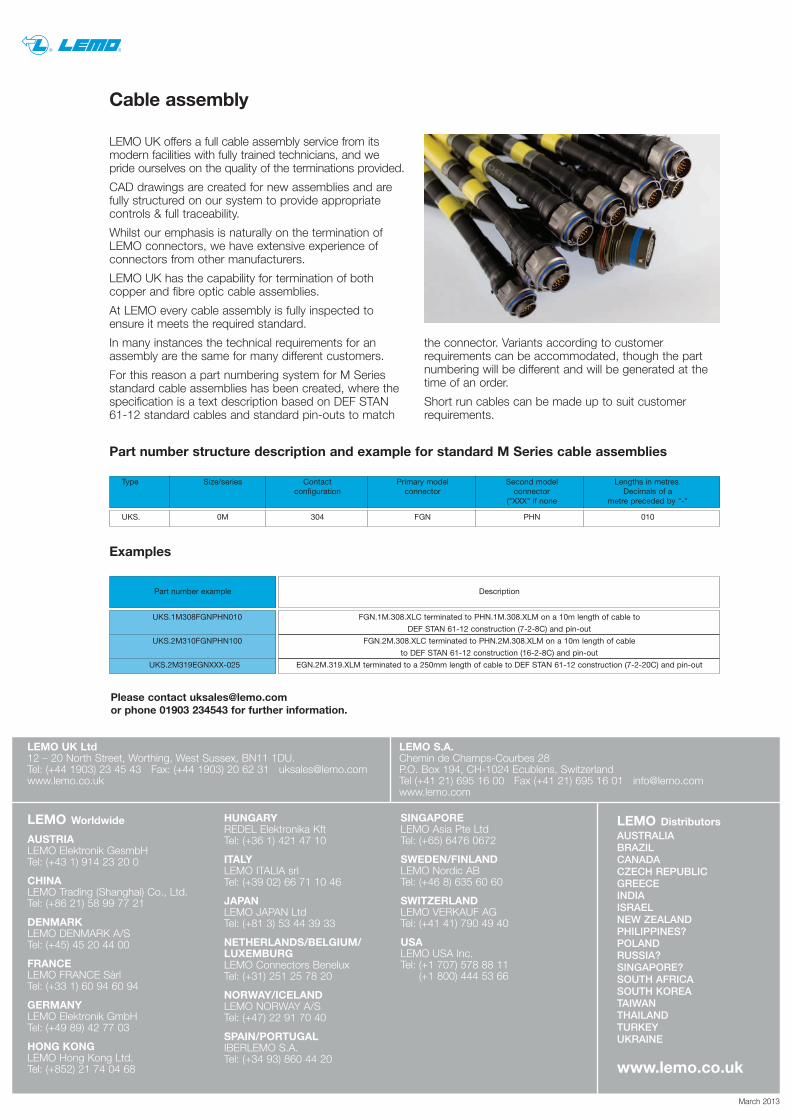
Cable assembly
LEMO UK offers a full cable assembly service from itsmodern facilities with fully trained technicians, and wepride ourselves on the quality of the terminations provided.
CAD drawings are created for new assemblies and arefully structured on our system to provide appropriatecontrols & full traceability.
Whilst our emphasis is naturally on the termination ofLEMO connectors, we have extensive experience ofconnectors from other manufacturers.
LEMO UK has the capability for termination of bothcopper and fibre optic cable assemblies.
At LEMO every cable assembly is fully inspected toensure it meets the required standard.
In many instances the technical requirements for anassembly are the same for many different customers.
For this reason a part numbering system for M Seriesstandard cable assemblies has been created, where thespecification is a text description based on DEF STAN61-12 standard cables and standard pin-outs to match
Type Size/series Contact Primary model Second model Lengths in metres. configuration connector connector Decimals of a
("XXX" if none metre preceded by "-"
UKS. 0M 304 FGN PHN 010
Part number structure description and example for standard M Series cable assemblies
Examples
Part number example
UKS.1M308FGNPHN010
UKS.2M310FGNPHN100
UKS.2M319EGNXXX-025
Description
FGN.1M.308.XLC terminated to PHN.1M.308.XLM on a 10m length of cable to
DEF STAN 61-12 construction (7-2-8C) and pin-out
FGN.2M.308.XLC terminated to PHN.2M.308.XLM on a 10m length of cable
to DEF STAN 61-12 construction (16-2-8C) and pin-out
EGN.2M.319.XLM terminated to a 250mm length of cable to DEF STAN 61-12 construction (7-2-20C) and pin-out
the connector. Variants according to customerrequirements can be accommodated, though the partnumbering will be different and will be generated at thetime of an order.
Short run cables can be made up to suit customerrequirements.