Embed Size (px)
Citation preview

NOT MEASUREMENT SENSITIVE
MIL-HDBK-5400 30 NOVEMBER 1995 SUPERSEDING MIL-STD-5400 15 JUNI; 1992
MILITARY HANDBOOK ELECTRONIC EQUIPMENT, AIRBORNE
GENERAL GUIDELINES FOR
'·
THIS HANDBOOK IS FOR GUIDANCE ONLY. DO NOT CITE.THIS DOCUMENT AS A· REQUIREMENT.
AMSC N/A AREA GDRQ . DISTRIBUTION STATEMENT A. Approved for public release; di_stribution is unlimited.

Mil-HDBK-5400
FOREWORD
1. This military handbook is approved for use by all Departments and Agencies of the Department of Defense.
. . 2. Beneficial comments (recommendations, additions, deletions) and any pertinent data which may·be of use in improving this document should be addressed to: Commander, Systems Standardization, Code 4.1.4.28120-3,. Naval Air Warfare Center Airct·aft Division, Highway 547, Lakehurst, NJ 08733-5100, by using the self-addressed Standardization Document Improvement Proposal (DD Form 1426) appearing at the end of this document or by letter.
3. This handbook provides gui.dance for implementing and tailoring guidelines and documents contained in Mll-HOBK-454 Standard General Guidelines for Electronic Equipment, whi.ch have applicability in the design .and production of electronic equipment for airborne applications. Included in this handbook are ref~rence·s to the applicable requ.irements, an index of applicable documents, and a guide for tailoring and application of those requirements and documents in conjuncti~n with the var1ous equipment design, development.and production phases. ·
ii

PARAGRAPH
I. 1.1 1.1.1 1.1. 2 1.2 I. 2 .I
2. . 2 .I 2.2 2.3
3. 3 .I 3.2 3.3 3.4 3.5 3.6 3.7 3.8 3:9 3.10 3.11 3.12 3.13 3.14 3.15
4. 4 .I 4 .I. I 4.1.2
4.1.3 4.2
. 4. 2 .I 4.2.2 4.2.3 4.2.4 4.2.5 4.2.6 4.2.7 4.2.7.1 4.2.7.2
MIL-HDBK-5400
CONTENTS
SCOPE . . .. Scope Application Tailoring .. Classification . External cooling
APPLICATION DOCUMENTS Documents . . . .
. Applicable issues Copies ..
DEFINITIONS Accessory . Acquisition activity Airborne· ...... . Complete operating equipment Detail specification Electronics ....... . Equi~ment ........ . Hermetic sealing ...... , Installation (complete equipment) . Intermittent and short time operation Other component definitions ..... . Performance requirements of the equipment Permanently installed part· .. Removable assembly ..... . Reordered production equipment
GENERAL GUIDELINES ..... . Untitled .......... · ... . Tailoring of MIL-HDBK-454 guidelines ... Standard hardware acquisition and reliability
program (SHARP) . . . . Requirements, tables and figures Design and construction .... .Untitled : .. . Accessibility .... . Anti-jamming .... : . Castings, metal . . . . . . .. Corona and electrical breakdown prevention Derating .. . . . . . . . . . . · Electrical overload protection Resettable circuit protectors Spare fuses
i i i
PAGE
I ' I
I I I 2
2 2 2 2
2 2 2 2 2 3 3 3 3 3 3 3 4 4 4 4
4 4 4
4 5 5 5 5 5 6 6 7 7 7 7

PARAGRAPH
4.2.8 4.2.8.1 4.2.8.2 4.2.9 4.2.10 4.2.11 4.2.11.1 4.2.11.2 4. 2.12 4.2.13 4.2.14 4.2.15 4.2.15.1. 4.2.16 4.2.17 4.2.17.1 4.2.17.2 ·4. 2.17. 3 4.2.18 4.2.19 4.2.20 4.2.21 4.2.22 4.2.23 4.2.23.1 4.2.23.2 4.2.23.3 4.2.24 4.2.25' . 4.2.26 4.2.27 4.2.27.1 4.2.27.2 4.2.28 4.2.28.1 4.2.28.2 4.2.28.3 4.2.29 4.2.30 4.2.30.1 4. 2.31 . 4.2.31.1 4.2.31.2
\
'·
M1L-HDBK-5400
CONTENTS. (cent i nued)
Electrical pojer ......... . Warm-up time . . . . . . . . . . . . Untitled ............. . Electromagnetic interference control El~ctrostatic discharge control Enclosures .......... . Stan'dardized avionics 'enclosures Other enclosures . . . . . . · . . Fabrication ......... .
. Grounding, bonding and shielding Human .engineering ...... . Interchangeability .......... . Interchangeability of reordered equipment Maintainability ...... . Mar:ki ng , . . . . . . . . . . Labels . . . . . . . . . . . . Wire coding for identification Operational program·marking Microphonics ..... . Moisture pockets ... . Multiplexing ..... . Nomenclature assignment Orientation ..... . Panels . . · . . . . . . . Control panels ..... Electroluminescent panels Ranges. of adjustable parts Pressurization Reliability Repairability Safety . . . . System safety . Personnel safety Test provisions .. Built-in test devices External test points
. Failure effect ... Testability program Thermal design ... Cooling design data Tools ..... . Setscrew wrenches Speci'al tools
iv
· .
.·
.·
PAGE
7 7 7 7
. 7 8 8 8 8 8 8 8 8 9 9 9 9 9 9 9 9 10 10 10 10 10 10 10 11 12 12 12 12 12 12 12 12 12 13
. . 13 . '13
13 . 13

PARAGRAPH
4.2.31.-3 4.2.32 4.2.33 4.3 4. 3.1 4.3.1.1 4.3.2 4.3.3 4.3.4 4.3.4.1 4.3.4.2
4.3.4.3 4.3.4.3.1 4.3.4.4 4.3.4.5 4.3.5 4.3.6 4.3.7 4.3.8 4.3.8.1 4.3.8.2 4.3.9 4.3.9.1 4.3.9.2 4.3.9.3 4.3.10 4.3.10.1 4.3.10.2 4.3.10.3 4.3.11 4.3.12 4.3.13 4. 3.14 4.3.15 4.3 .16 4. 3.17 4.3.17.1 4.3.17.2 4.3.17.3 4. 3.18 4.3.18.1 4.3.18.2 4.3.18.3 4.3.18.4
MIL-HDBK-5400
CONTENTS (continuedi
Furnishing and stowing .. Standardized power supplies Workmanship . . . Parts selection . . . Government furnished baseline (GFB) Choice of parts Nonstandard parts Parts control program Approval of parts . Contracts under category I .
. •
Contracts for equipment which fall under categories I I and I I I . . . .
Reordered production equipment Continuation of production Replacing of approved parts Equipment performance Substitution of parts Batteries . Bearings . Capacitors Fixed, ·tantalum, electrolytic Aluminum electrolytic Circuit breakers . , . Manual operation .... Position identification Orientation· . Connectors, electrical . . Mounting.of electrical receptacles
.Adjacent locations . Jacks . . . . . Controls (knobs, handles, dials) Crystals (quartz and oscillator) Fastener hardware .... Filters, electrical . Fuses, fuseholders and associated hardware Gears Hydraulics Aircraft Missiles Untitled
·.
Lights and associated items Indicator lights . Press to test indicator lights Instrument lights Lamps
v
PAGE
13 13 13 14 14 14 14 14 16. 16
16 16 16 17 17 17 17 17 1} 17 17 17 . 17 18
. .18 18 18 18 18 18 18 18 19 19 19 19 19 19 19 19 19 19 19 19

PARAGRAPH
4.3.18.5 &·':tlAI'O -y • .., • .~. ........
4.3.19 4.3.20 4.3.21 4.3.21.1 4.3.21.2 4.3.22 4.3.22.1 4.3.22.2 4.3.23 4.3.24 4.3.25 4.3.26 4.3.27 4.3.27.1 4.3.27.2 4.3.27.3 4.3.28
'4.3.29 4.3.30 4.3.30.1 4.3.30.1.1 4.3 .30.1. 2 4.3.31 4.3.31.1 4.3.31.2 4.3.31.3 4.3.32 4.3.33 4.3.34 4.3.35 4.3.35.1 4.3.35.2 4.3.35.3 4.3.35.4 4.3.35.5 4.3.35.6 4.4 4.4.1 4.4.2 4.4.3 4.4.4 4.4.4.1 4.4.5-
MI L-HDBK-5400
CONTENTS (continued)
Visual display and legend lights Night v·ision compatibility . Meters . . . . Microelectronic devices. Motors .. Motors, alternating current Motors, direct current ·Readouts and displays Readouts . Displays . . Relays .. Resistors ... Semiconductor devices Servodevices, rotary . . Sockets, shields and mounting pads Sockets Shields Mounting pads Springs . . . Standard electronic modules (SEMs) Switches Mounting Rotary switches Toggle switches Terminations . . . . Number of wires per terminal or lug Number of lugs per terminal· . . Number of wires in a connector contact Transformers, inductors and coils Tubes, electron : . . . . . . Waveguides and related items Wire and cable ...... ~ Wire and cable, internal Wiring practices, internal . Wire and cable, external interconnection External wiring practices Cable, coaxial (RF) . . . . . -Printed wiring ..... . Material selection . . . . Choice of materials .. Polyvinyl chloride (PVC) materials Standard ma'terials . Nonstandard materials Approval of nonstandard materials Adhesives
vi
PAGE
20 20 20 20 20 20 20 20 20 20 20 20 21 21 21 21 21 21 21 21 21 21 21 21 22 22 22 22 22 22 22 22 22 23 2:i 23 23 23 23 23 24 24 24 24 24

PARAGRAPH
4,4,6 4.4.7 4.4.8. 4.4.9 4.4.10 4.4.11 4. 4.12 4.4.13 4 .4.14 4.4 .15. 4.5 4. 5.1 4. 5. l.J 4.5.1.2 4. 5. 1. 2 .1, 4.5.1.2.21
4.5.1.2.3 4.5.2 4.5.3 4.5.4 4.5.4.1 4.5.4.2 4.5.4:3 4.6 4.6.1 4.6.1.1 4.6.2 4.6.2.1 4.6.2.1.1 4.6.2.1.2 4.6.2.2 4.6.2.3 4.6.2.4 4.6.2.5 4.6.2.5.1 4.6.2.5.1.1
4 .•6 • 2 • 5. 1. 2 4.6.2.5.1.3 4.6.2.5.1.4 4.6.2.6 4.6.2.6.1 4.6.2.6.2 4.6.2.6.3 4.6.2.7
MIL~HDBK-5400
CONTENTS (continued)
Arc-resistant materials ...... . Con forma 1 coating . . . . . . . Dissimilar materials ........ . Encapsulation and embedment materials Fibrous material, organic ..... . Flammability of materials ..... . Fungus-inert materials ........... . Insulators, insulating and dielectric materials Lubricants .......... . Metals, corrosion resistant Processes and finishes ..... Protective platings and coatings Materials . · ......... . Aluminum alloy ........ .
. Surface, general· ........ . Surfaces, bonde~ and grounded ·. ·. Surfaces, extreme wear·resistant Magnesium and magnesium alloys Zinc and zinc-plated parts .. Finishes .......... . Cases and front panels ... . Fasteners and assembly screws Other standard finishes .. Environmental service requirements MIL-STD~810 environmental tests . Untitled ....... : .... . Equipment operational requirements Temperature Operating . . . . . . . . . . . Nonoperating . . . . . . . . . . Altitude ....... .' ... . Temperature-altitude combination Humidity . . . . . . . . . . . . Vibration .......... . Equipment normally.mounted .......... . Equipment designed for installation in propeller
aircraft ......... · .......... . Equipment designed for installation in jet aircraft Equipment nesigned for installation in helicopters Minimum integrity test Shock . . . . . . .. Equipment ...•. Mount1ng base (crash safety) Bench handling Sand and dust
Vl1
.·
PAGE
25 25 25 24 25 25 25 25 25 25 26 26 26 26 26 26 26 2.6 28 28 28 28 28 28 28 29 29 29 29 29 35 35 35 35 35
35 35 35 35 36 36 36 36 36

PARAGRAPH
4.6.2.8 4.6.2.9 4.6.2.10
5. 5.1 5.2 5.3 5.3.1 5.3.2 5.3.3 5.3.4 5.3.5 5.3.6
"5.3.6.1 5.3.7 \
I
5.4
6. 6.1 6.2
6.3 6.4 6.5
FIGURES
1
2
3
4
TARLES
I I I Ill IV v
MIL-HDBK-5400
CONTENTS (continued)
Fungus . . . . ... Salt atmosphere Explosive conditions
DETAIL GUIDELINES . . . . . • . . .. Detailed mechanical and electrical design Technical data ............ . Quality assurance .......... . Responsibility for tests and inspections Government verification ..... . Failure criteria ........... . Problem/failure reporting and corrective action Design qualification tests First article tests Scope of tests ...... . Qu'al ity_ conformance tests Preparation for delivery
NOTES . . . . . . . . . . Intended use . . . . . . . . . . Details for inclusion in equipment specifications
and contracts . . . . Use of helium ....... . Publications . . . . . . . . . Subject term (keyword) listing
Operational requirements for class I airborne ~
lli1 36
·' 36 36
37 37" 37 37 37 37 37 38 38 38 38 38 39
39 39
39 40 41 41
electronic equipment (temperature vs altitude) .. 31 Operational requirements for.class 2 airborne
electronic equipment (temperature vs altitude) 32 Operational requirements for class 3 airborne
electronic equipment (temperature vs altitude) 33 Operational requirements for class 4 airborne
electronic equipment (temperature vs altitude) 34
General design and construction 6 Parts selection . . . . 15 Materials selection 24 Processes and finishes 27 Environmental conditions 30
viii

APPENDIX A APPENDIX S
INDEX
MIL-HDBK-5400
CONTENTS (continued)
APPLICABLE DOCUMENTS . SAMPLE TAILORING GUIDE
ix
-.
PAGE
A-I B-1
. . 1-1
MIL-HDBK-5400
1. SCOPE
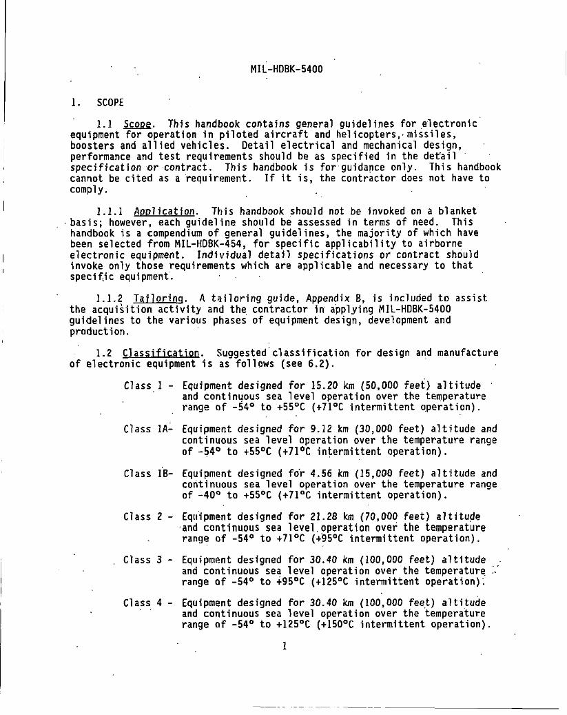
1.1 Scope. Thl s handbook contains general guidelines for electronic· equipment for operatiqn in pilot•d aircraft and helicopters,· missiles, boosters and allied vehicles. Detail electrical and mechanical design, performance and test requirements should be as specified in the det'a i 1 specification or contract. This handbook is for guida!'lce only. This handbook cannot be cited as a requirement. If it is, the contractor does not have to comply.
1.1.1 Application. This handbook should not be invoked on a blanket . basis; however, each guideline should be assessed in terms of need. This
handbook is a compendium of general guidelines, the majority of which have been selected from MIL-HDBK-454. for specific applicability to airborne electronic equipment. Individual deta.il specifications or- contract should invoke only those requirements which are applicable and necessary to that specif,ic equipment'.
1.1.2 Tailoring. A tailoring guide, Appendix 8, is included to assist the acquisition activity and the_ contractor in· a·pplying MIL-HDBK-5400 guidelines to the various phases of equipment design, development and production. ·
1.2 Classification. Suggested-classification for design and manufacture of electronic equipment is as follows (see 6.2). ·
Class 1 - Equipment designed for 15.20 km {50,000 feet} altitude · and contin4ous sea level operation over the temperature range of -54° to +55°C (+71°C intermittent operation}.
Class 1A~ Equipment designed for 9.12 km (30,000 feet} altitude and continuous sea level operation over the temperature range of -~4° to +55°C (+7l°C intermittent operation).
Class iB- Equipment designed fo'r 4.56 km (15,000 feet) altitude and continuous sea level operation over the temperature range of -40° to +55°C (+71°C intermittent operation).
Class 2 - Equipment designed for 21.28 km (70,000 feet) altitude ·and continuous sea level.operation over the temperature range of -54° to +71 °C (+.95°C i.ntermi ttent operation).
Class 3 - Equipment designed for 30.40 km (100,000 feet) altitude and continuous sea level operation over.the temperature. range of -54° to -i-95°C (+125°C intermittent operation):
Class 4 - Equipment designed for 30.40 km (100,000 feet} altitude and continuous sea level operation over the temperature range of -54° to +125°C (+150°C intermittent operation).
1
---- -- ··-- ------------------

Mil-HDBK-5400
Class 5 - Equipment designed for altitudes greater than 30.'40 km (100,000 feet) for periods of time not exceeding 6 hours and continuous sea level operation over the temperature · range of -54° to +95°C (+125°C intermittent operation).
1.2.1 External cooling. The addition of the letter. "X" after the class number, e.g., (Class 2X), will identify the equipment as operating in the ambient environment of that class, but requiring cooling from a source external of the equipment.
2. APPLICABLE DOCUMENTS
2.1 General. The documents listed in Appendix A are not necessarily all of the documents referenced in this handbook but are the ones that are needed to fully understand the information provided by this handbook.
2.2. Apolicable jssues. · Unl.ess otherwise specified, the applicable issues of documents listed in Appendix A are those listed in the·Department of Defense Index of Specifications and Standards (OOOISS) specified in the solicitation. The applicable issue of·nongovernment documents not listed in the DOD ISS should be the issue specified in the solicitation.
2.3 Copies. Copies of specifications, standards, handbooks, drawings and ·publications required by contractors in connection with specific acquisition functions should be obtained from the acquisition activity or as directed by the contracting officer. ·
3. DEFINITIONS
3.1 Accessory. ·An accessory is an assembly of a group of parts or a unit which is not always required ·for the operation of a set or·unit as originally designed but serves to extend the functions or capabilities of the .. set, such as headphones for a radio set supplied with a loudspeaker, a vibratory power unit for us·e with a set having a built-in power supply, or a remote control unit· for use with a set having integral controls.
' 3.2 Acqyjsition activity. The mili~ary or federal agency contracting for equipment.
3.3 Airborne. For purposes of this handbook, the term "airborne" combines applications of electronic equipment wHhin aircraft, helicopters, missiles, boosters and allied vehicles as defined and limited by the . classifications and guidelines contained herein. •
3.4 Complete operating eoujpment. Complete operating equip~ent is defined as equipment, together with the necessary detail parts, accessories and components, or any combination thereof, required for the performance of a specified operational function. Certain equipments may be complete within
2

MIL-HDBK-5400
themselves and not require the addition of.detail parts, accessories or components to perform a specified operation a 1 function.
3. 5 Deta i1 specification. For purposes of this. handbook, the term "det.il specification" is·defined as the document which describes and controls the detail features of a specific equipment for. acquisition by the Government. These details include, but·are not limited to, such features as mechariical· and electrical design parameters, quality and reliability requirements, performance and environmental requirements. The detail specification may be prepared by the Government, the equipment manufacturer for-the Government, or the prime vehicle contractor. The preparing activity of the detail specification should utilize the·applicable guidance contained in this handbook in the preparation of that speci fi cation. · ·
3~6 Electronics. The term "electronic~" is defined as a system or equipment, the primary purpose of which is the transmission or reception of intelligence. This·includes or comprises communications or signal equipment, radio, ·radar, radiation, radio-controlling devices, meteorological, fire control, bombing, flight and navigational instruments, powerplant" controls, synchronizers, photographic· ·and test equipment, when such port ions emp 1 oy circuits which utilize a combination of electrical ·or electronic devices to generate, control,· indicate or record any form of alternating or direct currents, or both.
3.7 Equipment. ~quipment is a general term characterizing the broad category of electronic Hems (units, subsystems, systems, etc.).
3.8 Hermetic sealirig. Hermetic sealing is the process by which an item is totally enclosed by a suitable metal structure or case by fusion of metallic or ceramic materials. This includes the fusion of metals by welding, brazing or soldering; the fusion of ceramic ~aterials under heat or pressure; and the fusion.of ceramic materials into a metallic support.
3.9 Installation <complete equjpmentl. An installation (complete equipment) is defined as a combination of assemblies, accessories and detail parts required to make one complete operating equipment. An installation . comprises a group of permanently installed parts and a ·group of removable assemblies. ·
3.10 Intermittent and short-tjme operation. Intermittent and short-time operations are the alternating periods of· ope rat i. on for the specified ·time after which the equipment should be required to remain operational following the high temperature transient. · ·
3.11 Other component definitions. For definitions of part, subassembly,. assembly, unit, set, system and models, MIL-STD-280 will apply.
3

MIL-HDBK-5400
3.12 Performance requirements of the 'equipment. Wherever referenced in this document, the "performance requirements of the equipment" is to be understood to mean the satisfactory performance of all electrical and mechanical characteristics performed under the "condition," "destructive," and "accelerated life" tests described in the detail specification for the purpose of simulating anticipated field. service demands as closely as possible.
3.13 Permanently installed part. A permanently installed part is defined as a detail part or assembly which is permanently installed as a_part of the vehicle. Examples: Rigid or whip antenna, bracket, cable assembly, fairlead, mounting and plug.
. 3.14 Removable assembly. which is easily removable from indicator unit, radio receiver
A removable assembly is the vehicle. Examples: and radio transmitter.
defined as an assembly Dynamotor unit,
3.15 Reordered production equipment.. Reordered production equipment is equipment acquired on each contract after the original Category III contract for the .equipment, regardless of 'the contractor, e.g., if contractor "X" is granted the1original production, then the equipment acquired on a second or
· subsequent contract is considered reordered production equipment, whether it is acquired from contractor "X" or· a riew contractor.
4. GENERAL GUIDELINES
4.1 This section contains general guidelines for common application to all airborne electronic equipment design and construction. Also included in this section are requirements for the design selection and application of parts, materials and processes; selected primarily from MIL-HDBK-454 as
.applicable to airborne ele~tronic equipment:
4.1.1 Tailoring of MIL-HDBK-454 guidelines. The guidelines of MIL-HDBK-454 have been tailored for inclusion in this handbook, and those documents applicable to airborne electronic equipment extracted and specified herein. Appendix A of this document lists those documents extracted from MIL-HDBK-454 determined to be suitable for airborne electronic equipment applications. The extent of applicability of any individual MIL-HDBK-454 .... ,.;:~,..,.;: ....... .;:~ 1.;-.;+,...1 + ... ,.. .. 1 .. +a.. ... r- ... ~ ... ,.. .. .,o .. +ro .t'!.v+ ... ~,.+or4 .,. .. A l.;r-+.or4 ; .. l\nnonrt;v YUIUCIIIIC: I~ IIIIIII..'C:;U l.U UIIIJ' \.IIU~.:::; UU\oUIIU:::III.~ ~1\ .. ID'"-11.1;;\.1 DIIU ll~l.~\ol Ill npp~~;;IIUI"'
A. Where reference is made to a_complete MIL-HDBK-454 guideline, all documents listed in that guideline are considered applicable unless otherwise supplemented or restricted herein or in MIL-HDBK-454.
4.1.2 Standard hardware acqyisition and reliability program (SHARP). This handbook is intended primarily for use in the design of militarized developmental electronic equipment for airborne applications. However, the use of militarized non-developmental items (NO!), standardized under SHARP for airborne electronics, should be utilized to .the maximum extent possible.
4

L
MIL-HDBK-5400
SHARP developed hardware includes standard electronic modules (SEMs}, standard enclosure systems (SES}, standard power supply systems (SPS}, and standard battery systems (SBS)·. SEMs should be implemented in accordance with MIL-STD-1378, SES in accordance with MIL-STD-2200, and SPS in accordance with MIL-STD-2038. Non-use of SHARP requires approval of the acquisition activity.
4.1.3 Requirements. tables and figures. Tables I through IV contain reference to subject matter cross-referenced to the applicable MIL-HDBK-454 guideline or MIL-HDBK-5400 paragraph number. Table V provides a crossreference of temperature and altitude ranges to the applicable class of equipment for tests under operating and nonoperating conditions. Figures 1 through 4 provide operational (temperature vs altitude} requirements for the various classes of equipment.
4.2 4.3 4.4 4.15 4 .'6
Requirement
General Design-and Construction· Parts Selection Materials Selection Processes and Finishes Environmental Service Requirements Figure I - Operational Requirements
Class I, lA, IB Figure 2 - Operational Requirements
Class 2 Figure 3 - Operational Re9uirements
Class 3, 5 Figure 4 - Operational Requirements
Class 4
4.2 Design and construction.
Table
I II
III IV v
4.2.1 Table I lists general subject areas for consideration in the design and construction of airborne electronic equipment.
4.2.2 Accessibility. Guidance for accessibility to parts, wiring and terminations within equipment is contained in MIL-HDBK-454, Guideline 36.
4.2.3 Anti-jamming. The electronic system or equipment should be designed to obtain the maximum inherent protection against possible interfering signa 1 s caused by enemy jamming. The contractor should soli cit and obtain the approval of the acquisition activity for the basic anti-jamming concepts before proceeding with the design of the models.
5

MIL-HDBK-5400
Accessibility Anti-Jamming Castings · Corona Derating
Table I.
Subject
General ~\~..,..,..;,...,. \AC;:) 1\.UI
Electrical overload protection Electrical power Electromagnetic·interference control Electrostatic discharge control Enclosures Fabrication Grounding, bonding & shielding· Human engineering interehang~abi1it~ Maintainability Marking Microphonics Moisture pockets Multiplexing
·Nomenclature Orientation Panels Pressurization Reliability Repairability Safety Test provisions Testability program Thermal design Tools Sta"ndard power supplies tJn.,..lrm:anc:h;n nvo n.UIU.IIJII I
and '"""r-t""'"'"t;nn \..VII~"' Y ... " .......
MIL-HDBK-:5400 Parilgraph
4.2.2 4.2.3 4.2.4 4.2.5 4.2.6 4.2.7 4.2.8 4.2.9 4.2.10 4.2.11 4.2.12 4.2.13 4.2.14 .4_ ') 11:. .... , . .,~..., 4.2.16 4.2.17 4. 2.18 4.2.19 4.2.20 4.2.21 4.2.22 4.2.23 4.2.24 4.2.25 4.2.26. 4.2.27 4.2.28 4.2.29 4.2.30 4.2.31 4.2.32 4,2,33
MIL-HDBK-454 Guideline
36
21 45 •n !O 8 25 61 75 55
74 62 7
54 67
31
34
35
I 32 32 52 63
9
4.2.4 Castings. metal. Metal castings.should be designed, classifi~d, inspected and repaired in accordance with MIL-STD-2175. Porous nonferrous castings should be impregnated in accordance with·MIL~STD-276. Refer to MIL-HDBK-454, Guideline 21 for guidance in the choice of casting process and repairs to castings.
4.2.5 Corona and electrical breakdown prevention. Equipment should be protected agaiRSt corona and electrical breakdown. Guidance regarding corona and electrical breakdown is given.in MIL-HDBK-454, Guideline 45.
6

MIL-HDBK-5400
4.2.'6 Derating. Guidance for derating of electronic parts and materials should be in given in MIL-HDBK-454, Guideline 18. In addition, derating should be accomplished based upon cooling conditions (either ambient or forced air) applied to the equipment when installed in the vehicle.
4.2.7 Electrical overload protection. Current overload protection for the equipment should be provided by fuses or circuit breakers. Circuit breakers should not be used as switches unless such breakers have been specifically designed and tested for that type service. Protective devices employed in the equipment should be in a readily accessible, safe location.
4.2.7.1 ·Resettable circuit protectors. Circuit breakers or other resettable.devices should be used to protect critical circuits, or where predictable overloads or surges occur because of peculiar equipment functions or operator effects which are unavoidable.
4.2.7.2 .. Soare fuses. When fuses are used, a minimum of one spare fuse for ea.ch size and rating but a quantity of not less than 10 percent of the total should be incorporated in the equipment and should be contained ;n the s.ame compartment ..
" .
4.'2.8 Electrical power:. The equipment should be designed to operate from power sources in· accordance with MIL-STD-704.
4.2.8.1 Warm-up time. Warm-up time should be such as to provide the specified performance within a period as specified by the detail specification. Unless otherwise specified, the warm-up time at temperatures down to -54°C should not exceed 2 minutes for equipment essential to flight safety, and should not exceed 5 minutes for equipment not essential to flight safety. ·
4:2.8.2 Electronic eq11ipment which will require shipboard alternating current (ac) power to be supplied for purposes of test or aircraft servicing should have e1ectrlea1 interface characteristics compatible with the applicable.power system classification of.MIL-STD-13gg, Section 300.
4.2.9 Electromagnetic interference control. Guidance regarding e 1 ectromagnet i c interference control requirements, tests and test methods is given in MIL-HDBK-454, Guideline 61.
4.2.10 Electrostatic rlischarge control ... Requirements for the establishment and implementation of an electrostatic discharge control program, including its deliverable data requir9mentsi should be tailored for applicability to equipme.nt and specified directly in the contract or detail specification. MIL-HDBK-263 provides guidance for the implementation of an ESD control program. Also, refer to MIL-HDBK-454, Guideline 75, for additional guidance in this area.
7

MIL-HDBK-5400
4.2.11 Enclosyres.
4.2.11.1 Standardized avjonics enclosures. As an integral part of the. SHARP program (see 4.1.2), the selection of standardized enclosure systems should be as specified in MIL-STD-2200. Enclosures conforming to MIL-E-85726 and racks conforming to ·MIL-R-85725 are examples of standardized hardware which are available for use as conforming to the requirements of MIL-STD-2200.
4.2.11.2 Other enclosures. Guidance for the design and construction of other equipment enclosures (e.g.,· consoles, cabinets, cases),· is given in MILHDBK-454, Guideline 55, except that performance for mounting bases should be met at the same vibration test frequencies and energy density levels as required for the specific equipment. Mounts and vibration isolators, whether integral or not, should be subject to approval of the acquisition activity. Positive self-lockinQ case mountinQ fasteners should be used on all mountinqs. The fasteners chosen-should be of a size specified for the weight of the -equipment unit.
. . .. 4.2.12 fabrication. Boxes, cases, shields and compartment walls sh~uld
be made by casting, .drawing· or bending, and welding, brazing or adhesive bonding except when ease of servici.ng of the equipment requires that a removable panel construction be used. When the applied stresses dictate the use of a strong aluminum alloy which does not provide a good weld or braze, riveting or bolting may be used ..
4.2.13 Groundjng. bonding and shielding. Grounding, bonding and shielding interface and installation requirements should be in acco.rdance with MIL-B-5087. MIL-HDBK-274 provides guidance information relative to grounding practices for aircraft. Refer to MIL-HDBK-454, Guideline 74, for guidance covering Air Force applications.
4.2.14 Human engineering. Requirements for human engineering should be provided and tailored for applicability to ·the equipment and specified directly in the contract or detail specification. MIL-STD-1472 provides design criteria which may be selectively applied. Refer to MIL-HD8K-454, Guideline 62, for guidance covering Air Force applications.
4.2.15 ·Interchangeability. Provisions should lie taken to assure for the interchangeability of parts, subassemblies, and assemblies. Information regarding interchangeability is contained in MIL-HDBK-454, Guideline 7.
· 4.2.15.1 Intercha~geability of reordered equjpment. For reordered equipment, interchangeabil.ity should· exist between units and all replaceable
.assemblies, subassemblies and parts of a designated model of any previously manufactured equipment supplied or designated by the acquisition activity.
8

MIL-HDBK-5400
4.2.16 Maintainability. Requirements for the establishment of a maintainability program (maintainability program· tasks, quantitative requirements, and verification or demonstration requirements) tailored for applicability to the equipment and program phase, should be specified directly in the contract or detail equipment specification. Other maintainability requirements which may be invoked and cited directly as. a basis for contract are contained in MIL-STD-471. MIL-HDBK-472 gives guidance regarding maintainability programs for electronic equipment. ·
4.2.17 Mark1no. Guidance for' the marking of items is given in MIL-HDBK-454, Guideline 67. Marking· should not adversely affect the leakage path
.between conductors or any other factor of ·equipment performance.
4.2.17.1 Labels. Labels showing wiring and schematic diagrams of parts, lubricating and operating instructions, safety notices, list of tools, list of contents and similar information should be provided where .space permits: La be l,s should be designed to ·remain 1 egi bl e and affixed for the service 1 i fe
·of the equipment on which they are mounted.
4.2)17.2 wire coding for identification. ·Hookup wires in the equipment should be distinctly coded hy color or· numbers, insofar as practicable. Codes should be in accordance with MIL~STD-681, unless otherwise specified. Short hookup wire, 150mm or less in length between termination points, need not be marked if the path of the wire can be easily and visually traced. Numbers should not be used where they would be difficult to read or trace. Flat cable conductors may be identified to termination points. The outer conductor of a flat multiconductor cable should be coded continuously for identification and orientation. Hot or cold stamp should be allowed·only on insulated wire which will not accept ink. Marking should not be used on·wires where the dielectric· capability of the wire is reduced by sucn marking. Wire used for external wiring between units should be coded in accordance with MIL-W-5088.
4.2.17.3 Operational program marking. Operationally programmed units should provide a means to identify the software part number and the revision of the software program. Guidance is provided by MIL-HDBK-454, Guideline 67.
4.2.18 Microphonics. Equipment should be designed so that.microphonics are not detrimental to equipment performance.
4.2.19 Moisture pockets. Guidance for.~he treatment and drainage of moisture pockets is given in MIL-HDBK-454, Guideline 31.
4.2.20 Multiplexing. Unless otherwise specified, multiplexing should be used to transmit bilevel signals for logic functions for ON-OFF, interlocking ~nd· proportional control of utilization equipments and components. The multiplex data bus system should be in accordance with MIL-STD-1553. MIL-HDBK-1553 provides guidance information for implementatio·n of MIL-STD-1553.
9·

MIL-HOBK-5400
4.2.21 Nomenclature assignment. Nomenclature assignment should be in ·accordance with MIL-STD-196, along with MIL-N-18307.for the Navy, MIL-STD-1812 for the At r Force, and the contract for the Army. · - ·
4.2.l2 Orientation. Normal installation position or range of positions should be as specified.in the detail specification. The equipment ahould operate within specified limits in any position specified in the detail specification.
4.2.23 Panels ..
4.2.23:1 Control oanels. Console and rack mounted control panels should conform to MIL-C-6781 and Mll-C-81774. Control panels should be integrally · illuminated and conform to the requirements of MIL-P-7788.
4. 2. 23.2 -El ectrol umj nescent pane 1 s. The use of el ectrol umi nescent panels r~quires approval of the acquisition activity.
4.2.23.3 Ranges of adjustable parts. The electronic circuitry should be designed to) provide a reserve in the adjustment range from the normal adjustment· setting of all variable parts that require adjustment during operation or maintenance. This adjustment range should be sufficient to compensate for composite variations which may develop in the associated circuitry because of normal changes in part values during the specified life cycle of the equipment. The adjustment range should also be capable of compensating for variations resulting from replacement with parts within the·
.tolerances specified. ·
· 4.2.24 Pressurization. Whenever pressurization of the electronic equipment is required, or is utilized to meet specification requirements, the following provisions should be met:
a. The case should withstand a positiVe or negative difference over the applicable pressure range.
·. 5 psi pressure
b. The case should be of a type that will permit ready opening and clearing for access to the equipment for repair and maintenance. If practicable, the equipment should be completely operable after removal from the case, and alignment should be unaffected by replacement in the case, · ·
c. When possible and advantageous, external points should be provided for check without remova 1 from the case ..
10

MIL-HDBK-5400
d. A means should be provided for determining the effectiveness of the seal. This·may consist of an automobile-tire-type valve stem fitting to permit the use of an air pump for increasing the pressure approximately 5 psi above sea level pressure. A Schrader type 3715 gage, or equivalent slrould be used to me.asure the pressure.
e. Sealing instructions should be placed on one side of the case, if practicable.
f. Those parts of an equipment, including transmission lines, that are pressurized should be capable of withstanding any pressures deve 1 oped under the required extern a 1 ope rat i.on conditions, ·after .having been pressurized initially on -the ground to not more than 5 psi gage at -20°C to +50°C, to such a.n extent that no .arcing or loss of power caused by corona occurs that would not occur at atmospheric pressure on the ground. Nor should leakage be such as to permit the entrance of moisture or air to an extent that permanent damage or impaired operation occurs under any of the required operating
'conditions. Vacuum relief valves should be provided ..
g. Unl\ess specified or permitted in the detail specification, pressure should be. maintained without the ·use or need of a pressurization pump. When a pressurization pump is required, redundant barostatic switches, or similar automatic means, should be provided to assure equipment is pressurized during flight, even though it is not being operated. The switch or automatic means should be energized from a common point and should be energized from a common point and should be energized as part of the take-off procedure. · · ·
h. The· equi pm.ent should rna i ntai n pressure to accommodate the maximum operating time; in addition., and where app 1 i cab 1 e for captive and
·nonoperating flight, the equipment should maintain operating pressure for periods up to 24 hours. Unless otherwise .determ.ined as satisfactory, the loss of pressure shou1d.not exceed 5 pounds in a 24-hour period at the altitude and temperature specified in the detail specification. · ·
i. If required, a desiccant should be provided within the case.
j. Parts used in pressurized container should meet th~ guidelines of this handbook, except that the altitude. _conditions may differ .
. 4.2.25 Reliability. Requirements for the establishment of a reliability program (reliability enaineering and accounting tasks, quantitative requirements, and verification or demonstration requirements) tailored for
ll

MIL-HDBK-5400 ·
. . applicability to the .equipment and program phase should be specified directly in the contract or detail specification. Other reliability requirements which may be invoked and cited directly as.a basis for contract requirements are contained in MIL-STD-1629. MIL-HDBK-217 gives additional guidance regarding reliability programs for electronic 'equipment. ·
4.2.26 Repajrabiljtv. Repairability should be_determined in terms of warranties, mean time to repair (MTTR}, stocking spare replacement parts and identifying procedures and personnel for the repair of the specified equipment. The.detail equipment specification should specify the MTTR for militarized-equipment, not to exceed thirty (30) minutes. Level of .. repair guidance is provided in MIL-STD-1390, and should be evaluated when making repairability and training decisions.
4.2.27 Safety.
4.2.27.1 System safety. Requirements for·the development and . implementation of a system safety program should be tailored for applicability to the equipment and-acquisition phase and specified directly in the contract or.detail specification. , .
4.2.27.2- Personnel safety. Guidance provisions for safety of personnel during installation, operation, maintenance and repair is provided in MILHDBK-454, Guideline 1.
4 .. 2.28 Test proyjsions. Test provisions to provide means for monitoring _performance, calibration and fault isolation should be directly specified in the detail specification or contract. Refer to MIL-HDBK-454, Guideline 32 for guidance in this area. ·
4.2.28.1 ~uilt-in test devices. Built-in devices should maintain their accuracy under a 11 operating conditions required by the equipment under test. These devices should be provided with connections or access for·their · operational checkout or calibration.
4.2.28.2 External test pojnts. Protection should be provided in the test point circuitry to prevent equipment damage caused by the external grounding of test points.
4.2.28.3 Failure effect. Unless otherwise specified, provisions for . testing should be so designed that any failure -of built-in test devices will not degrade equipment operation or cause equipment shutdown.
4.2.29 Testability prngram. Requirements for the development and implementation of a testability program (program planning,' design, prediction, demonstration, data, and review} should be tailored for applicability to the equipment and program phase, and specified directly in the contract or detail specification.
12

MIL-HDBK-5400
4.2.30 Thermal design .. Guidance for thermal. design is contained in MILHDBK-454, Guideline 52, and MIL-STD-2218.
4.2.30.1 Cooling design data. Cooling· design data should be developed as soon as possible after major circuit parameters have been established. Tn;.i-i'!l11H fok.(,. d'!l+'!l·r ... nii1A in,..l .. do. l"''!ll,...,l'!l+in."'r d"''!lld;n"r :::ronrf n+ho. ... in.fn,..m!II-J.III"'ID.I IJ' \olll::/1 II,,QI.Q ~IIVUIU 111\..IUU~ \,.D.I'-'U1Q\o1V11~t U\ Q'nlll':;tOJ OiA1I'Iol U ... U¥1 ln1VIIll04
tion related to the choice of a particular cooling.system configuration. As part of this initial data, the first set of applicable the.rmal design evaluation data should be developed, based on preliminary calculations at the specified .operating conditions. The approval of the cooling system will be based upon consideration of this information. Applicable part temperatures from these calculations should be utilized in the reliability prediction analyses. As equipment development proceeds, this data should become more fina.l and. should be based on more actual thermal test results. Upon completion of the engineering development or preproduction modelsi and when required by the contract, a thermal evaluation test program should be conducted. Refer to MIL-:-SID-2218 for additional guidance in this area.
4.2.31 Tools. \ .
4.2.31.1. Setscrew wrenches. One wrench for each size and type setscrew head employed for operational adjustments should be securely mounted within the equipment in a readily accessible ·location. Each wrench should be processed to resist corrosion .
. 4.2.31.2 Special tools. Special tools include jigs, fixtures, stands, and templates not l_isted in the. Federal Supply Catalog, require approval of the acquiring activity. for use. The design of equipment should be such that the need for speci a 1 tools for tuning, adjustment, ·maintenance, replacement, and installation is kept .to a minimum. Only when the required function cannot be provided by an existing .standard tool ·should special tools be considered. Necessary tools should be identified as early as possible.
4.2.31.3 Furnishjng and stowing. Special tools needed for operation and organization level maintenance should be furnished by the contractor except that the contractor should not mount tools in the ·equipment or make space provisions therefore, unless required by the detail ·specification or contract.
4.2.32 Standardized power supplies. As an integral.part of the SHARP program (see 4.1.2}, the selection of·standardized power supplies for airborne applications should be as specified in MIL-STD-2038. Power supplies conforming to MIL-P-29590 should be ·of primary consideration for airborne applications. ·
4.2 .. 33 Workmanshjn. Guidance for workmanship of mechanical .assembly should be applied as given in MIL-HD8K-4~4, Guideline 9.
13

L __ _
MIL-HDBK-5400
4.3 Parts selection·.
4. 3.1 Government-furnished baseline IGFBl. When ·Specified by contract or system specification, the applicable GFB should be the primary selection ·source for standard parts (see 4.3.3). The applicable GFB parts should meet the special part selecti.on standard requirements referenced herein (e.g., 4.3.24 for MIL-STD-199 resistors). Table II provides identification of parts which are included in the applicable GFB. GFB parts, when specified by. contract requirement, hold prior approval status. All parts listed in the· app1icable GFB are considered standard parts and should be used whenever suitable.
4.3.1.1 Choice of parts. When.ever the applicable selection standard, GFB or specification provides multiple characters or tolerances on items, the equipment manufacturers should consider the use of the broadest
. characteristics and greatest allowable tolerances to. fulfill the overall requirement. The manufacturer should also consider limiting the variety of part types and review the system Program Parts Selection List (PPSL) for candidates prior t9 reachi.ng a part decision. All new equipment should be designed t~ accommodate.the maximum envelope dimensions specified ~n the military part specification. ·
. 4.3.2 Nonstandard parts.- When the applicable GFB fails to provide .the required part or Appendix A does not provide an applicable part standard or specification, the contractor should select a part from other established specifications or standards specified i n·the contract or by the design
_activity. Nonstandard parts must be equivalent' to or better than ·similar standard parts and must be compliant wi.th applicable contract requirements. Each vendor source for nonstandard parts documented by a source control drawing requires approval of the acquisition activity.
4.3.3 Parts control program .. Requirements for the implementation of a contractor parts control program, including pa_rts approval by the acquisition activity, should be directly specified in the detail specification or contract. Refer to M1L-HDBK-454, .Guideline 22 and MIL-HDBK~402 for guidance in this area. A Military Parts Control Advisory Group (MPCAG} review .in accordance with the requirements if MlL-STD-965 should be considered.
NOTE: The Parts Control Program requires the approval and listing of all parts in a PPSL unless the requirements have been otherwise tailored.
14

MI L-HDBK-.5400
TABLE II. Parts selection.
Subject
Batteries Bearings Capacitors Circuit breakers Connectors, electrical Controls (kn.obs,· handles, dials) Crystal units· (quartz) Fastener hardware Filters, electrical Fuses & fuseholders Gears Hydraulics Lights.and associated items Meters, electrical indicating Microelectronic dev1ces Motors 1
Readouts .and displays Relays Resistors Semiconductor devices Servodevices, rotary Sockets, shields and mounting pads Springs
·standard electronic modules (SEMs) Switches . · Terminations Transformers, inductors and coils Tubes, electron Waveguides and related items Wire and cable Wire and cable, internal Wiring practices, ·i nterna 1 Wire and cable external interconnection Cable, coaxial (RF) Printed wiring
15
MIL-HDBK-5400 Paragraph
A ~ ~ "t • .J.'tJ
4.3.7 4.3 .8 4.3.9 4.3.10 4.3.11 4.3.12 4.3.13 4.3.14 4.3.15 4.3.16 4.3.17 4.3.18 4.3.19. 4.3.20 4.3.21 4.3.22 4.3.23 4.3.24 4.3.25 4.3.26 4.3.27 4.3.28 4.3.29 4.3 .30 4.3.31 4.3.32 4.3.33 4.3.34 4.3.35
4.3.35.1 4.3.35:2 4.3.35.3 4'.3.35.5 4.3.35.6
MIL-HDBK-454 Guideline
27 6 2 37 10 28 38 12 70 39 48 49 50
40 & 51 64 46 68 57 33 30 56 60 41 73 58 19 14 29 53
20 & 66 69 71 65 17

MIL-HDBK-5400
4.3.4 Approval of parts. In considering the approval of parts, contracts for electronic equipment are divided into the following categories:
Category I: Contracts which are fundamentally for the purpose of investigation or study and not for the fabrication of equipment.
Category II: Contracts for one or more models of equipment designed to meet the performance requirements of a specification or to establish technical requirements for production equipment. This category includes contracts for models to be used for test under service conditions for the evaluation of their suitability and performance.
Category II I: Contracts· for production equipment. These contracts wi 11 usually include requirements for a prototype or first article model. ·
4.3.4.1 Contracts under Category I. Approval of parts should not be required under ·contracts or orders which fall under Category I. General parts information, is avaUable upon request to the Military Parts Control Advisory Groups (MPCAGs).
4.3.4.2 Contracts for equipment which fall under Categories II and III. ·For a single contract covering like equipments·which fall in both·categories ··II and III, parts approval should be required only for those items· used fn Category II equi pments, and any new item sources. or new nonstandard items us.ed in Category Ill equipment. As specified by contract, approval of all parts used in the equipment should be obtai ned by the contractor prior to de 1i very
. of any equipment required by the contract.
4.3.4.3 Reordered pro~uction equipment. A design review directed toward replacement of nohstandard p.arts with standard parts should be performed on contracts for reordered equipment, whether reordered from the original contractor or from a different contractor. Where applicable, the PPSL listing should be utilized for the review function by the MPCAGs. Changes must conform· to interchangeability requirements.· The original part procured from the same source, when required by interchangeability.or lack of a standard replacement part, may be used without. reapproval.
4.3.4.3.1 tontinuation of production. In those cases wherein the reordered production equipment represents conti.nuous production by the same contractor, a review directed toward nonstandard parts replacement with standard parts is not required.
16

MIL-HDBK-5400
. 4.3.4.4 R'i§;lacinq of aporoved parts. Whenever permission is sought by the contractor use an item that is not the part approved for use in the system/equipment, the procedure used should be a "Request for Deviation" in
·accordance with the applicable configuration management requirements of the contract. The standard/approved item. should be listed ·in technical manuals, parts lists, etc.
4.3.4.5 Eouipment performance. The guidelines in this handbook regarding the use of parts, eitner standard or approved nonstandard, should not relieve the contractor of the responsibility for.complying with all equipment performance and other requirements set forth in the detail specification or contract. Approvals ·for nonstandard parts are contingent on subsequent satisfactory performance during required equipmeri~ tests.
4.3.5 Substitution of parts. Information regarding the selection and application of substitute parts is given in MIL-HDBK-454, Guideline 72.
4.3.6 Batteries. acquisition 1activity. given in MI~-HDBK-454,
The use of batteries requires approval of the Batteries should be selected and applied using guidance Guideline 2?. ·
4.3.7 Bearings. Bearings should be selected and applied using guidance given in MIL-HDBK-454, Guideline 6.
4.3.8 Capacjtors. Capacitors should be selected and applied in accordance with MIL-STD-198.
4.3.8.'1 fixed; tantalum electrolytjc. for Naval Air Systems Command, · the use of wet slug tantaltfm capacitors (except tantalum-cased units in
accordance with MIL-C-39006/22 and MIL-C-39006/25) requires the approval of the acquisition activity, and s i 1 ver-cased tanta 1 urn capacitors should not be used.
4.3.8.2 .Aluminum electrolytic. Aluminum electrolytic capacitors should not be used in airborne electronic equipment applications.
4.3.9 Circyit breakers. Circuit breakers should .be selected and applied. in.accordance with MIL-STD-1498. Trip-free circuit breakers should be used. Nontrip-free circuit breakers should be used only when the application requires overriding of the tripping mechanism for emergency use ..
4.3.9.1 Manyal operation. Circuit breakers should be capable of being manually operated to the ON and OFF positions. Circuit breakers should not be used as ON-OFF switches unless such breakers have been specifically designed and tested for that type· of service.
17

MIL-HDBK-5400
4.3.9.2 Position identification. Circuit breakers should have easily identified ON, OFF and TRIPPED positions except that the TRIPPED position may be the same as the OFF position with no differentiation between OFF and TR I PP.ED being required. · ·
4.3.9.3 OrjentatjOn. Circuit breakers should operate when permanently . inclined in any. direction up to 30 degrees from the normal vertical or normal horizontal position. The trip point of an inclined unit should not vary more than +5 percent of the current 'specified for normal position mounting. Ci'rcuit breakers used on flight equipment should operate within the limits of the detail spec-ification when the equipment is in any position or rotation about its three principal axes. ·
4.3.10 Connectors, electrical. Electrical connectors should be selected and applied in accordance with MIL-STD-1353. Additional selection and application guidance is given in MIL-HDBK-454, Guideline 10.
4.3.10.1 Mounting of electrical receptacles. Where practical, when receptacle~ are mo~nted on a vertical surface the largest polarizing or prime key or keyway of the receptacle should be at .the top center of the shell of the receptacle. Mounting connectors on a top horizontal surface should be avoided, in order to prevent pooling of moisture in the connector. However, when necessary, the master keyway should be forward if designated.
4.3.10.2 Adjacent locations. MIL-W-5088 gives requirements for the spacing of electrical connectors used in adjacent locations.
4.3.1'0.:3_ Jacks. Microphone jacks should be type M641/5-l and headset jacks should be type M641/6-1 conforming ·to MIL'-J-641. Use of these jacks for other than microphone and headset use is prohibited in areas accessible to flight personnel.
Jl ':1! 11 rr~."'+"'""'l~· /ltnnh~ h!tonl'floc- rt;::alc-\ t"nnt-ronl tfnnhc: c:hnulfi hP .,. 1., o J. J. \.;Ufll.l U I~ I I"'.IIUL.P~ o IIU.II\.1 I 'Eo:!' t ... I U, I~ f o ""VII .... .., I ,,..,..,...,_, "'"""""" 1 'W --
selected and applied in accordance with MIL-K-25049. Handles should be ·selected and applied in accordance with MIL'-H-8810. Multiturn counter control dials should be selected and applied in accordance with MIL-D-28728. Additional application information is specified in MIL-HDBK-454, Guideline 28.
4.3.12 Crystals {quartz. and oscillator). Quartz crystal units should be selected and applied in accordance with MIL-ST~-683. Crystal oscillator units should be in accordance with MIL-0-55310.'
4.3.13 Fastener hardware. MIL-HDBK-454, Guideline 12 gives information regarding applicable fastener specifications, mounting methods and techniques.
'(
18

MIL-HDBK-5400
4.3.14 Filters. electrical. Electrical filters· should be selected and applied in accordance with M1L-STD-1395.
4.3.15 Fuses. fuseholders and associated hardware. Fuses, fuseholders and associated hardware should be selected and applied in accordance with MIL-STD-1360 .. Additional guidance information is provided in MIL-HDBK-454, Guideline 39.
4 .. 3.16 Gears. Gears s~ould be designated, dimensioned, toleranced and inspected in accordance with applicable specifications of the American Gear Manufacturers Association "(AGMA). Gears not operating in a lubricant bath should be made of a corrosion resistant material. Gears operating in a lubricant bath containing a corrosive inhibiting additive may be made of noncorrosive resistant material. Planetary. gearing is preferred to worm gearing. Non-metallic gears may be used when they meet the load, life and environmental requirements ~f the a~plicable specific~tion.
,4.3.17 Hydraulics. Hydraulic systems which function as an integral part of an electronic system should be as follows:
4.3).17.1 Aircraft .. The design and installation of hydraulic systems for aircraft should be in accordance wi.tlt<,the appl i cab 1 e type, c 1 ass or system of MIL-H-5440.
4:3.17.2 Missiles. The design and installation of hydraulic systems for missiles should be as specified directly in the detail specification or contract.
4.3.17.3 Additional guidance information and document references are provided ·in MIL-HDBK-454, Guideline 49. ·
4.3.18 Lights and associated items.
4.3.18.1 Indicator liqhts. Indicator~ lightS, light housings, lamp-holders and lenses should be selected and applied i.n accordanc~ with MIL-L-3661. . · .
4.3.18.2 Press to test indicator lights. Press to test in~icator lights should be selected and applied in accordance with MIL-L-7961.
' 4.3.18.3 Instrument lights. Instrument lighting should be integral red in accordance with MIL~I-25467, or integral white in accordance with MIL-l-27160; as required. The use of non-integral lighting requires approval of the acquisition activity, and when approved should be in· accordance with MIL-L-5057.
4.3.18.4 1AIDRi· Incandescent lamps should be selected and applied in accordance with MIL-L-6363. When used as indicator lights, light emitting diodes (LEOs) should be selected and applied in accordance with MIL-S-19500.
19

Mll-HDBK-5400
4.3.18.5 Vjsual display and legend lights. Visual display and legend 1 ights should comply with the requirements in MIL-STD-1472.
4.3.18.6 Night vision compatibility. When compatibility of equipment is required for night vision imaging, the requirements of MIL-L-85762 should apply.· ·
4.3.19 Meters: Panel type electrical' indicating meters should be selected and applied in accordance with MIL~M-10304 (color schemes.W, B, Y, F and P). Time totalizing meters should be selected and applied in accordance with MIL-M-7793. When required·, external meter shunts should conform to
· MIL-S-61 or.MIL~I-1361.
4.3.20 Mjcroelectronjc devices. Microelectronic devices, including hybrids, should be selected and applied using guidance given in MIL-HD8K-454, Guideline 64 .. Devices selected should be connected by means of soldering, .welding, or the use of shape memory metal alloy connectors.
4.3.21 Motors .
. 4.3.21\ · Moto~s. aHernating-current. Alternating current motors (400 Hz, 115/200.volt) should be in accordance with MIL-M-7969, except that motors used with a miniature blower for cooling electronic equipment should be in
·accordance with MIL-8-23071.
4.3.21.2 Motors. direct current. Direct current motors (28 volt) should be in accordance with MIL-1·1-8609.
4.3.22 Readouts and displays.
4.3.22.1 Readouts.· Readouts should b~ selected and applied in · accordance with MIL-R-28803. ·
4.3.22.2 Qjsolays. Light emitting diode (LED) displays should be selected and applied in accordance with.MIL~D-87157, quality level A or B. Liquid crystal displays (LCDs) exhibit limited operation of temperature extremes, and require acquisition activity approval for use in airborne electronic equipment.
4.3.23 ·Relays. ·Relays· should be selected and applied in accordance with MIL-STD-1346. Hermetically sealed types only should be used. Reed relays should be in accordance with MIL-R-83516, and require acquisition activity approval for use in airborne electron)c equipment.
4.3.24 Resistors. Resistors should be selected and applied in accordance with MIL-STD-199. Thermistors should be in accordance with MIL-T-23648.
20

MIL-HDBK-5400
4,3.25 Semiconductor devices. Semiconductor devices should be selected and applied in accordance with MIL-STD-701. Information concerning the order of precedence and restrictions in the selection of semiconductor devices is given in Mll-HDBK-454, Guideline 30.
4.3.26 Servodevfces. rotary. Guidance concerning the selection and application of rotary servodevices is given in MIL-HDBK-454, Guideline 56:
4.3.27 Sockets, shields and mounting pads .
. 4.3.27.1 Sockets. Sockets for plug-in electronic parts should be o'f the single unit type and should conform to MIL-S-12883, MIL-S--83502 or MIL-S-83734. The use of sockets for microcircuits requires approval of the acquisition activity.
4.3.27.2 Shjelds. Heat dissipating tube shields should conform to MIL-S-24251.
4.3.27.3 Mounting pads. Where mounting pads are required for use with small el e'ctri cal or electronic devices, they should conform to A-A-55485.
4.3.28 Springs. Springs and ~pring material should be selected and applied in accordance with MIL-HDBK-454, Guideline 41.
4.3.29 Standard electronic modules ISEMsl. As an integral. part of the SHARP program (see 4.1.2), standard electronic modules (SEMs) conforming to MIL-M-28787 should be utilized to the maximum extent possible. SEMs should be designed in accoraance with MIL-STD-1389. SEMs should be applied in accordance with MIL-STD--1378. Guidance information for the SEMs program is contained in MIL-HDBK-246.
4.3.30 Switches. Switches and associated hardware should be· selected and applied in accordance with MIL-STD-1132.
4.3.30.1 Mounting.
4.3.30.1.1 Rotary swjtches. Rotary switches with thru-panel shafts should be mounted to the panel by means of.a single threaded bushing . concentric with the. shaft. A positive mechanical mean.s, in addition to lock washers, should be provided to prevent rotati_on of the switch body.
4.3.30.1.2 Tooele switches. The mountino of tooele switches should be such that the handle of the switch operates in- a vertical direction. The "off" position should be in the center position on three-position switches and in the bottom position on two-position switches. When clarification of a control function or convenience of operation would result {for example, a "left-right" function control), toggle switches may be so mounted that the handle of the switch operates in a horizontal direction. · ·
21

MIL-HDBK-5400
4.3.31 Termjnations. The selection of stud terminals, lug terminals, feed-thru terminals, binding posts, terminal boards, terminal junctjon systems and splices should be in accordance with MIL-STD-1277 .
. 4.3.31.1 Number of wires per terminal or lug. The number of wires terminated in an·individual termina·l or lug should not be greater than three. Multisection turret, bifurcated, or multi-hole lug terminals should have n'ot more than three wires per section, tong,·or.hole. In no case should the total cross sectional area of the terminated wires exceed the cross sectional area capacity of the· terminal or lug.. If a greater number of wires is required than 'those specified herein, approva 1 of the acquisition activity should be obtained. ·
4.3.31.2 Number of lugs per terminal .. The maximum numbe.r of lugs to be connected to any one ter·minal on a terminal. board should be two for screw-type terminal boards covered by MIL-T-55164 and as specified in the detail · specifi~ation sheets for stud-type terminal boards. Not more than four lugs should Be connected·to.any one terminal of a board covered by MS27212. Acces- · sories such as stud connectors, straddle plates, jumpers and terminal board
' 1 ugs should· be counted as .1 ugs for this purpose ...
4.3.31.3 Number of wires in a .connector contact. In order to facilitate contact insertion and removal and wire sealing, only one wire should be terminated in a crimp contact in an eiectricai connector.
4. 3. 32 Transformers .. inductors and coils. The selection and app 1 i catron of transformers, inductors and coils should be in accordance with · · MI L-STD-1286. Vari.abl e transformers should conform to MIL-T -83721; and intermediate radio frequency and discriminator transformers should conform to MIL-T -55631, Grade I, 2 or 4. Grade 3 transformers should be 1 imi ted to hermetically sealed or encapsulated assemblies.
4.3.33 Tubes. electron. Electron tubes should be selected and applied in accordance with MIL-STD-200. ·
4.3.34 Waveguides and related items .. Guidance concerning the selection and application of waveguides and related items is given in MIL,.HDBK-454, .· Guideline 53.
4.3.35 Wire and cable·. Wire and cable having polyvinyl chloride (PVC) or FEP/polyimide (Kapton) insulating material shoul'd not be used in ai:rborne electronic equipment applications.
4.3.35.1 Wire and cable, internal. Internal hookup wires conforming to MIL-W-227·59 and MIL-W-81044 are preferred for use within the equipment. Further information concerning restrictions of other wire types is given in MIL-HDBK-454, Guideline 20. Multiconductor cables conforming to MIL-C-7078
22

MIL-HDBK-5400
and MIL-C-27500 and utilizing the above specified wire types are preferred for use within the equipment. Other cable types are subject to the above restrictions and those of MIL-HDBK-454, Guideline 66. · ·
4.3.35.2. Wiring practices. internal. Internal wiring practices and wiring devices should conform to.M!l-HDBK-454, Guideline 69. Use.of organizational architectures, .i.e.; DIM (Organized wire, Integration boards, Mass termination), is strongly encouraged.,
4.3.35.3 Wire and cable. external interconnection. Wires conforming to MIL-W-227Sg ·and·MIL-W-81044,.as identified in MIL-W-5088, Appendix A, and cables conforming to MIL-C-27500 which utilize the above spe_cified wire types are preferred. per use for external interconnections between units. Other wire and·cable types are subject to the above restrictions and those of MIL-HDBK-454, Guide.Jine 71 and MIL-W-5088, as applicable.
4.3.35.4 ·External wiring practjces .. · The use of organized wiring· systems (OWS) architecture and wiring practices spe'cjfied in MIL-W-5088 is strongly encouraged to faci.litate reliabil-ity, maintainability, and reduction of weight.
\ . . I ' ,
4.3.35.5 Cable. coax·ial CRFL .Coaxial cables (RF) should ·selected the requirements of MIL-C-17, MIL-L-3890, MIL-C-22931, or MIL-C-23806.
using
4.3.35.6 Printed wiring. Printed wiring boards, assemblies, cards and associated liardware should be in· accordance with. MIL-STD-1861. Printed wiring boards should be connected· into the equipment by means of connectors. Printed wiring boards uti 1 i zing the conductor pattern as the direct contact with the : mating connector should not be used ..
4.4 Material selectjo~.
4.4.1 Chojce of materials. Table III provides a list of material applicable for use in the design and construction of airborne electronic equipment. Also included in the table is reference to corresponding MIL-HDBK-454 guidelines, where applicable, ~nd paragraphs herein which supplement or restrict the specific requirement. Whenever· an applicable material specification provides more than one characteristic or-tolerance, the equipment manufacturer should u~e.· in the equipment, material of broadest characteristics and of the greatest a 11 owabl e to 1 erances. that wi 11 fulfi 11 the performance requirements of the equipment. Whe.n acc;eptabl e materia 1 s of higher than minimum quality are readily available, the utilization of which would not increase the initial or life cycle ·cost to the acquisition activity, they may be used.
'23

Mll-HDBK-5400
TABLE III. Materials selectjon.
Subject MIL-HDBK-5400 Mll-HDBK-454 Requirement Guideline
Adhesives 4.4.5 23 Arc resistant materials 4.4.6 26 Conformal coating 4.4.7 --Dissimilar metals 4.4.8 --Encapsulation and embedment materials 4.4.9 --Fibrous materials, organic 4.4.10 44 Flammability.of materials 4.4.11 3 Fungus inert materials 4.4.12 4 Insulators, insulating and dielectric
materials 4. 4.13 11 Lubricants ' 4.4.14 43 Metals, .corrosion resistant 4.4.15 --
4.4.2 Polyvinyl chloride (PVC> materials. Polyvinyl chloride (PVC) materials shOuld not be used in airborne electronic equipment applications.
4.4.3 Standard materials. Materials covered by documents listed in Appendix A are considered standard and should be. used whenever they ·are suitable for the purpose. Materials should be acquired from QPL or QML sources when qualification is a requirement of the material specification.
·4.4.4 Nonstandard' materials. When Appendix A fails to provide an applicable material specification or 'standard, the contractor should select a material ·from other established specifications .or standards in accordance with the order of preference set forth in the contract. Nonstandard materials must be equivalent to or better than similar standard materials. Each vendor source for a nonstandard.material covered by a source control document requires approval of the acquisition activity. The request for approval of nonstandard material should be made at the time that the material is selected for use in the equipment design. The Government retains the right to request changes to the material, if the performance, description, test data or inspection of the material indicates that the material will not perform its intended function.
4.4.4.1 Approval of nonstandard materials. Requirements for. the acquisition activity approval of nonstandard materials should be specified in the detail specification or contract.
4.4.5 Adhesives. The guidelines contained in Mll-HDBK-454, Guideline 23 should be used when selecting and applying adhesives. The use of adhesives in electrical applications re(\uires the approval of the acquisition activity.
'24

MIL-HDBK-5400
4.4.b Arc-resistant materja1s. Arc-res1stant mater1a1s shou1a oe selected and applied using the guidance given in MIL-HDBK-454, Guideline 26 .
. 4.4.7 Conformal coating. Conformal coating for use with rigid printed ·circuit assemblies should conform to MIL-I-46058. . .
4.4.8 Pissi~ilar metals. Selection and protection of dissimilar metal combinations should be in accordance with MIL-STD-889. The use of dissimilar metals should be limited to applications where similar metals cannot be used clue to peculiar design requirements ..
4. 4. 9· Encapsul at jon and embedment materials. Encapsulation and embedment materials should be of a nonreversion type and should be selected from the following specifications: MIL-S-8516, MIL-I-16923, MIL-S-23586, MIL-M-24041, -and MIL-I-81550. The materials selected should be capable of filling all voids and air spaces in and around the items being encased. Refer to'MIL-HQBK-454, Guideline· 47 for additional guidance information.
A A 1n r.:"""""'''~' m-. .......... .:-.1 ,...,.,.~..,.;,. n,.n!ln.;,.. ~-'"'""""'ur m!to+.t•n••;!!ol rl-!1'\ulrl he "l'o-ro.&V \ [llJJUU~- IIIQLCJ IQio Ul"fGIII\oo VI::JU.II,I\o IIUIUU~ IIIQ"'t;l IQI ,o)IIV!o.IIU .,_
selected and applied using guidance given in MIL-HDBK-454, Guideline 44.
4.4.11 Flammability·of materials. Materials used in military equipment should, in the end item configuration, be noncombustible or fire retardant in the most hazardous conditions of atmosphere, pressure, and temperature to be expected in the application. Fire retar,dant additives may be used provided they do not adversely affect the specified performance requirements of the basic materials. Fire retardance should not be achieved by use of· nnr\n.a..,.m::an.on+ . '!lrlrH t-; u.o.r + n + h.o h!:l r i r m!llt.o.,..; ::a 1 Do~ol"' f' n M T I _1-fnR~ _,41:\d. IIVII ... 10iiiU ... IIt;ll"' QUUI ... IWW~ ... .., '-11 ......... .;JI'-> IIIIL& .. WI IWI• '".,1'-1 "'"' 11.0. .. ........ , ... --yv--.,
Guideline 3. for a9ditional· information on the testing of material to determine its· fl ammabi 1 i ty characteristics·.
4.4.12 Fungus-inert materials. The sel.ection and application of fungusinert and fungicide treated materials should be accomplished using the guidance provided in Mlt-HDBK-454, Guidelin~ 4.
. . 4.4.13 Insulators. insulating and-dielectric materials. The selection·
and application of insulators, insulating and ·dielectric materials should be made- using the guidance provided in MIL-HDBK-454,· Guideline 11.
4.4.14 lubricants. The selection and application o{ lubricants for airborne electronic equipment should be in acco-rdance with MIL-STD-838. · Standard lubricants -should be iimited to those given in MiL.:.HDBK-454, Guideline 43.· Refer to MIL-HDBK-275 for guidance relative to application and
_limitations of specific lubricants.
4.4.15 Metals. corrosjon resistant. Metals should be corrosion resistant or should be coated or metallurgically processed to resist
·corrosion. Materials and processes for metallic parts should conform_to
·----. ~~----------------

MIL-HDBK-5400
applicable requirements of MIL-STD-889 and MIL-STD-15.16. Coatings should be selected from MIL~STD-1516.
4.5 Processes and finishes. Processes and finishes, except painting, should be in accordance with Table IV and, where applicable, using the guidance of the referenced MIL-HDBK-454 guideline or supplemental paragraph herein. Welding. and brazing should be accomplished by certified operators in accordance with the requirements of MIL-STD-248 or MIL-STD-1595, as applicable. ·
4.5.1 Protectjve platings and coating. A protective plating or coating should be applied to all metals which are not corrosion-resistant, except as follows:
4.5.1.1 Materjals. Gold, nickel, chromium, rhodium, tin, lead-tin alloys, or sufficiently thick platings of these metals, are satisfactory without add!tional protection or treatment other than buffing or cleaning.
4.5.1.2 Aluminum allo~. \ . . . I .
4. 5 .I. 2.1 Surface. genera 1 . Parts fabricated from aluminum llOO, a 11 oys 3003, 5052, 6053, 6061, 6063 or 7072 should be cleaned with a deoxidizing solution, other than an uninhibited caustic dip, and may be used with or with
·out other surface treatment. Other aluminum alloys should be anodized in accordance with MIL~A-8625 or be given a chemical treatment in accordance with MIL-C-5541.
4.5.1.2.2 Surfaces. bnnded and grounded.· Where bonding or grounding is necessary, aluminum 1100, . a 11 oys 3003, 5052, 6053, 6061, 6063, 7072, or equally corrosion-resistant alloys, should-be used. They may be used without other surface treatment, ·
4. 5 .1. 2. 3 Surfaces. extreme wear resi slant. Where ·bondl ng or grounding is not necessary, hard anodic finish conforming to number E514 of MIL-F-14072 may be applied to obtain extreme wear-resistant surfaces under MIL-F-14072, Type II exposure on desired areas of aluminum alloys not subject to repeated high tensile. stresses.
4.5.2 Magnesium and magnesium alloys. Magnesium and magnesium alloys should not be used except when approved or specified by the acquisition activity-. The request· for use of magnesium and· its alloys should include the tota1 environment exposure, the weight reduction and other advantages achieved, _the proposed surface treatment and the application details.
26

MIL-HDBK-5400
TABLE IV~ Processes and finishes.
Subject Applicable process document
Anodizing/chemical film Anodize per MIL-A-8625 or chemical film per MIL-C-5541
Brazing MIL-B-7883
Cadmium plating 1/ QQ-P-416
Chromium plating QQ~C-320
Coatings and surface treatments MIL-S-5002
Finishes (S~e para. 4.5.4)
Gold· plating MIL-G-45204, Type II or III depending upon application
) Nickel plating Electrodeposited per QQ-N-290
Soldering, component mounting, etc. .- electrical/electronic.assembly
Soldering, fabricated assemblies, non-electrical
Tin plating
Welds, electrical·connections
Welds, structural (arc anrl gas)
~elds, structural (resistance)
Zinc coatinq
Refer to MIL-HDBK~2000 for guidance information
DOD-STD-1866
MIL-T-10727
MIL-W-8939 (Refer to MIL-HDBK-454, ·Requirement 24 for guidance information)
Aluminum alloys MIL-STD-2219 Magnesium alloys MIL-STD-2219 Steel alloys MIL-STD-2219
MIL-W-6858 (Refer to MIL-HDBK-454, Requirement 13 for guidance information)
Electrodeposited per ASTM B633
lL Except where equipment may be exposed to temperatures above 205°C (400°F) or where it may come in contact with petroleum-based products.
27

MIL-HDBK-5400
4.5.3 Zinc and zjnc-plated parts. Zinc and zinc-plated parts should be given a dichromate treatment in accordance with ASTM 8633.
· 4.5.4 Finishes. Unless contained in a hermetically-sealed unit, part finishes (including hardware items of equipment not covered by subsidiary specificati_ons) should be resistant to corrosion. Finishes should be capable of withstanding .a 48-hour Salt Spray (Fog) test in accordance with MIL-ST0-810, Method 509, Procedure I, without showing signs of corrosion beyond those established for the particular part, material or finish specification. Where applicable, these parts should have finishes providing suitable rates of heat lubricated condition. Lusterless finishes shbuld be used on all surfaces visible to operating personnel. Where cleaning. operations on metal parts are not specified in detail, they should be in accordance with MIL-S-SOOZ. It is not the intent that parts acquired to the specifications listed in Appendix A must be refinished.
4.5.4.1 Cases and front panels. Equipment installed in the cockpit area should be. Lusterless 81 ack, Col or No. 37038, in accordance with FED-STD-Sg5. Unless otherwise specified, finish of all other equipment should be Lusterless Gray, "Color No. 36Z3-l, in accordance with FED-STD-595.
I .
4.5.4.2 Fasteners and assembly screws. Exposed surfaces of external fiisteners and assembly screws used in areas other than the cockpit which are manipulated, loosened, or removed in the normal processes of .servicing and installing. the equipment should be finished, preferably in a noncorrosive black or bright finish, sa as to provide strong contrast with the color of the surface upon which they appear. Exposed surfaces of external fasteners and assembly screws used in the aircraft cockpit should be finished using the guidance provided in 4.5.4.1. Other external fasteners and assembly screws used for securing the internal parts to the chassis· should be similar in color to the surface upon which they appear.
4.5.4.3 Other standard finishes. Type I finishes .in accordance with MIL-F-14072 are approved as alternates to any differing requirements specified under the paragraphs an finishes, except that colors specified should be used. . .
4.6 Envjronmental service guidelines.
4.6.1 · MIL-ST0-810 environmental tests. The contractual use of. Mll--STD-810 for environmental testing requires the development of environmental management and test plans and engineering tasks to adequately tailor the specific test procedures, test conditions, variations, and limits for the life cycle environmental conditions which the equipment will realistically encounter. MIL-STD-810 provides details of these data requirements and reports and identifies the Data Item Descriptions (DIDs) which must be specified in the contract. Each specific test method required must be assessed for its applicability to the equipment deployment. The test method
28

MIL-HDBK-5400
must be tailored for the selection of appropriate test procedure, test duration, variations, limits, tolerances, etc., and invoked directly in the detail specification or contract. The services of an environmental specialist may be required to effectively tailor and apply MIL-STD-8iO into the detail specification or contract.
4.6.1.1 The following list of MIL-STD-810 tests and test method numbers is provided for reference only. Specific methods, test procedures and varia-· tions, and limits must be selected and stated directly in the detail specification or contract for the proper performance of these tests.
Low Temperature High Temperature Altitude (Low Pressure) Temperature Shock Shock Vibration Fungus ·· Salt Fog Humidity Bench Handling c:..,"~ .., ..... nllr+ JQII\.11 GIIU UU_, l,o
Explosive Atmosphere
Method No,
502 501 500 503 516 514 508 509 507 516 510 511
4.6.2 Egujoment operatjonal requjrements. The equipment should be designed and constructed that no fixed part or assembly becomes loose, no moving or movable part or control be shifted in setting, position, or adjustment, and no degradation be caused in the performance beyond that specified :in the deta i 1 specification during operation or after storage in ambient conditions,. as follows:
4.6.2.1 Temperature. The equipment should be exposed to the temperature conditions for the applicable class shown-in table V. Th~ ambient temperature within the specified temperature ranges may remain constant for long periods and may vary at a rate as high as 1 degree per secorid.
4.6.2.1.1 Operatjng. The equipment should be capable of operating under the conditions for the applicable class and within the ranges listed in c;olumns I, II, III and VII of table V.
4.6.2.1.2 Nonoperating. The equipment in a nonoperating condition should be capable of withstanding long periods of exposure to the temperature extremes and shock as listed in table V.
29

... c.
TABLE V. Enviromental conditions.
.. Eoutpment ooer&ti.M_ ; Equtpoont
oprrlttng and EautCRnt nonooentt~ taonoperating
Temper•ture utre~~es ror the chlllbtr Tempfrature A.lt1tude Temper&ture Tempenture hc\ttlout uttrat1 ceo\ \n~ _oro'i'h\ons.\ tosb\nH tes~Deuture·lltttude >hock Extre~Ms >hock
(qutp.tnt Cohan I Coii.IIR II Cohan Ill Col~ VI c I 'IS continuous lntfrllliltfnl short ·t1111! Col~.~~~n IV Cohmn ¥ Cohan VII Cohan VIII Coh11t1 IX Coh111n X
Cl.ss. I -~·c 30 11in. ... OefiMd by Defined by ... -~4"C to Su level ·57"( to ·57"C to ·~~·c •11"C. Cur'fl! A, curve 8, +71"( 130.0 tn. Hg.) •85"( +es·c
t1qure I ttgure 1 (3.4 ln. Hg,) . so.oao rt.
Chu lA. ·S<'C JQ IIIR. ... Oefintd by Defined by ... ·54"C to Su level ·57"C to ·57"C to t55"C +7l"C curve A, cune B, '!'71"( UO.O tn. tfll,) +85"( +85"(
figure 1 rt gure 1 (8.89 tn. Hg.) 30,000 ft.
' OeftRe<l by Su level Cltss 18 ·4D"C 30 •tn. ... Defined by ... ·40"C to ·S7"t to ·57"C to •SS"C +7l"C curve- A, curve B. +71"C (30.0 In, Hg.) +8S"C +8S"C !
figure 1 figure 1 (16.119 ln. Hg.) I 15.000 ft. 1/
Clus 2 ·ft4"C lO min. ... Oeftrted by Defined by · ... ·54"C to S11 level ·57"t to ·57"C to
I
+7l"C +95"C curve A, curve 8, +95"C tlO.O in. Hg.) · +9S't +95"C ftgure 2 ftgure 2 !!·~!., 112.:. Hg.)
IU,UUU Tt. I
Clus l ·54"C lO min. 10 min. Deftned by Defined by Defined by -s.·c to Se1 level ·57"C to -57"C to +95"C +lZS"C +lSO"C curve A, curve 8, curve c, +125"C t3D.O tn. Hg.) +125'C +lZS"C
ttvur• 3 ltvure 3 figure 3 tD.32 tn. Hg.l 100.0110 ft.
Clus 4 ·14'C 30 min, 10 atn. Oeftned by Defined by Defined by ·54"C to Se1 level ·57"C to ·57"C to i +IZS"C +lSO"C +260"C cune- A, curve 8, curve c. · +lSO"C (30.0 tn. Hg.l +lSO"C +lSO"t
ftgur-e 4 figure 4 .figure 4 (0.32 tn. Hg.) 100.000 ft.
Chn S ·S<'C .30 •ln. ... 511111! IS . .. ... ·S4"t to · S~! lt¥!1 ·S7"C: tc ·57"t tc
l +95"t +12.5"( tlus l 1/ +125"C (30.0 ln. Ho. J +lZS"C +lZS"C UO.IO tn. Hg.) 2.000.000 ft.
Altitude r1nge s~ h for oper1Uon only. · !I ll
tlusu lA md lB equtQ~Rnt shauld withstand • nonootu.tlnfi 1ltttude of 40,000 Cel!t (S.S .tn •. llg.l. · for &llitude above 100,000 ft., tht equtpMnt's surrounding environment should not uceed 71"C &nd muns should be &YIIhble for reJettton of heat Into the surroundings by conduction. radllllon or~ SCat! oth!r lll!&ns.
:3: -,..... I
::t: 0 ~-1
"' ... 0 c:>

w ......
21.28 km (70,000 It)
18.24 km (60,000 It)
i5.20 km (50,000 It) ~!§g~~~~~~~trd!~~~~~!Frn!IJ
1U o 12.16 km (40,000 It) ::> t:: t-.. J" <(
6,08 km (20,000 It)
3.04 km ( 10,000 It)
0
TEMPERATURE °C
FIGURE 1. .Operational guidelines for class I airborne electronic equipment (temperature vs altitude).
::;:: ..... r . :I: 0 tD
'"' . U1 ~ 0 0

w ~ :::l l-i= ..J 4:
w N
21.28 km (70,000 Ill
18.24 km (60,000 II)
15.20 km (50,000 II)
12.16 km (40,000 II)
kY~II--DESIG~ED TO OPERATE CONTINUOUSLYD\i!!t1m1:f'l·\ !IT I ldl - AT 71.r. AT ~F;:A LEVEL. _ . __ .\ . .
• 1!!1..-rrt:::~O+H+~'· • ·-- ••• --·· --;-·,---- lli!ii!i!ilm:L!L4\.~
6.08 km (20,000 II)
·3.04 km ( 10,000 II)
0 -so -40 -30 -20 -1 o 0·. 10 20 30 40 50 60 70 60 . 90 100
TEMPERATURE °C
FiGURE 2. Ooerational guidelines for class 2 airborne electronic equipment (temperature vs altitude}.
:3:: ..... r ::r 0
"" ;><: . U"l .... 0 0

w w
w c· :::> t-i= .J <
.
33.44 km ( 11 0,000 Ill · nnmHmmmwnnrnmll ~··· 1w
. I CLASS 3 EQUIPMENT I litn 30.40 km (100,000 iti
.t . 11tfl}f!1f~D:Ji!.l.~ttJtJ!tA~!.' . t lt~.~i ~ .. :cURVE C-DESIGN AND TEST REQUIREMENTS :
l~ FOR SHORT TIME OPERA T:ION OF ELECTRONIC : I • EQUIPMENT DESIGNED TO OPERATE
. CONTINUOUSLY AT 95°C AT SEA .LEVEL.
2 7.36 km (90,000 fl) ' . . ' . I !IJ : IJ.I!' I I : . •t .. 1 f"lJ' ' .. ' ~t. ' j .t I 1 H ...
• 24.32 km (60,000 ttl ' 1
I
21.28 km (70,000 It)
18.24 km (60,000 It)
•.. ·. I I • I. , . ~ ' ; CURVE B-OESIGN AND TEST 1
15.20 km (50,000 It)
12.i6·km (40,000 fl)
9.12 km (30,000 Ill
6.06 km (20,000 II)
·3.04 km C 10,000 ttl
0
REQUIREMENTS FOR INTeRMITTENT : • . OP.ERA TION OF ELECTRONIP EQUIPMENT I . . 11 'I . . t
. DE!i~IGNED TO OPEl'lATE CONTINUOUSLY. .. . . ., t . ' AT 95~ AT SEA LEVEL. . . . I .I
i l r
1 . . . ' .. I .· ~ IX . : t l . I ·I . •
. . . . . r . .J . -1 • • I CURVE A- DESIGN AND TEST REQUIREMENTS ' '] J 1 J t· ·1· · t 1 I
lmHJt~8tli~~~{N~~~~~t?{;~~T~p1~rr~U:CTRCt.::c ~.1\:~ ~~, I 1 '~t ~1 : ' ,f, .;1~· ,.1· AT 96"cAt SEA'LEVEL .• j' I 1 i\! ·J 1
I . ' l. 'iJ• IJ . I I ' . I i II! . . : J l 'tlij . I '" •I .t rn' . . . . ., . .t I . . : I ! I
.. . • • '" I 1 I • 1
· . · .. · ·' · ·. ·. ~ •: . • I . · ·11 · '! · : · · · . · . . ! · . J.. . af m j !,, ; 1 1 , · ' tn !11
lfff!f:tW!ltf!tlll.U#ttlttJti11HI!tjtiJ1H!Uitltll1111.!U1111f!N!IUI II I· !11111! II Pill; lUi r!!l)JII III!!IW !i 1111
-so -40 -30 -20-10 0 10 20 30 40 5() 60 70 80 90· 100 110 120 130 140 150 160 170
TEMPERATURE °C
FIGURE 3. Ooerational guidelines for class 3 airborne electronic equipment (temperature vs altitude>.
::.:: ..... r . a OJ 7': . "' .p. 0 0

UJ 0 ::l !: t-...J <(
w .,.
33.44 km (110,000 111 ... ,., ... , ··• ....... ,.,I'· ···I :1.:}.1 ,., .. ·· ~ ;_; ;;;i :::; :!: ~-~:: :~ :i~~ ::~ ;.: -:: .:·· ... ·:·T· '1· I ...
30.40 km ( 100,000 fl)
. " ''I" .... "' ., :· ::·· :•: :· .... .::: .::: ss A EO 'I· :• : 1: ;!_1 :·;: !' ... ·.: ,: .::: ;'• .! .. ·::: :·:: CLA .. UIPMENT.J:
.... , .. , ... , ... , ... , ., ... :::; ;::: ::;; :·:: :::: · .. ; :::
27.36 km (ilO,OOO·fu I" 'l:; l' 'l" l'''l :: i l "l·::l \1· .,1. ::T '·l:''l':' 'l''' I"' "I ·. I'·::!'''' ::· ... , ···= ~,,,,,,,, '1•·- '•I" .:·' • ...•. -··· :··· . .1, ··•· ··:• •. • • •... • • •: • • • • • ' of I: I '!·' • I • ~ · • I • o, • • • • · • I: • •. • _.:____ _ ___: . . . . . ...
'J"ii):ra:-;l~::z.t:;:::;:r:;:;:;:;:r;:;:::n:::;:;:::r:::=:r:::::::"fC1-:-::T7:1:~: ' .. ' . • . : . . : . ' .. " ~-,ffi!tl:t!tt!'lt¥t+i:ftl~
24.32 km (80,000 111
21.28 km (70,000 111'"
18.24 km (60,000 111
15.20 km (50,000 ttl
12.16 ·km (40,000 111
9.12 km (30,000 Ill
6.08 km (20,000 ttl
3.04 km ( 10,000 II)
Q
'. ~~~~~~ .. ~---~·-:~,:i---~~---+--~~
,_,_. I" ' ~ i
;;;: ::·· ::: !::1 ' . ::!· ....
l'''lXYil-'1\'l'·l''·l·r·r·l··l·l r·l \! · ... trl! -~ .; ! .••. . '· · .-:: !!·n !::: :::· ··· · · · ... .. . I · •. , .. ........ ,. ;,.. . .... , ......... ~:.: . ·: .. : : :: :::: .:. -~: ..
fil'' ~:,,:1 ~~ l':.li'l :'~ti~:~l~lll Ti ll T--Fl "';':>~ .:: ,::· ::··:q -~:00::.: .. ::: :: : .:: ~ :: : . <>· : ;-!.: :;: :;,: ::; __ -:: ~-:i ~~~i ~L~ :t_: :;.: :;·; <·: :::: :::: =:• -:: · :: · ·::--:. · · '"I"·'Kc .. l .... l~f""'T .. "J!·· I ·. I ·J·. ·J· "I" I·'· 1:\:::l;j;:I\:''J' '1· .. \f:~[::C:I::;;I ·1· . I·:· :I' ·1:: I": r\
!iii ;: !It • ;
. , CURiJEC.:-OESrQN AND TEST REQUIREMENTS _ . . , . . . ! l FOR SHORT TIME OPERATION OF ELECTRONIC · · · : · ! ' .. ; :
I" .. ,, , . , EQUIPMENT DESIGNED '(0 OPERATE I
n !ij CONTINUOUSLY AT 12~C AT SEA LEVEL ; : ::ii ...... '1'1 " . ::" '.
"'cffi."l" I :·r 1'\'l''i-l'''\'"l' r 1·' .. '1 ,,,, .. ,,1·· ·1 ''·I.'' 1'''·1·'~ ·'I'·'' .,., .... .... . .. .. : .•. ,. I"'' :··· .: ..... ··- .•.. .. . . . ' .. .. .. .· ... I_ ...... , " ••• • •• '. ! • • .. . t.. . . .. .. " . • . .. . . • • .
l"lilpi:"l'''l:l"''i" :1'. I''' 1:·:~'1" ''"I\".. . .. . . .. . ... . . .• u ~.-.!.'.J~'-·'' !_•_••·!•.a;::_~_-- :.':'::;;n l.:.!;; ii;i . :: ;!:. -·: ·::: ·.:· .::: :; .. · :· '. \ .:. A· DESIQN A~O TEST REQUIREMENTS· .. ·'.. · '. .. .. .. · .. .. · .. · · •NTINUOUS OPERATION Of ELECTRONIC !: :::· :.\.!: . . ·: ... :·: .. ,. ;;;, • .. ' · .. :' ·\· ·:
......... ENTOESIQNEDTOOPERATE · , .. , ·:\ ·• ... · · · .. ,. .. . ... JAT 125"C AT SEA LEVEL . . . :· .::. ::, .: . . :: .
llll.I111'1'·1"P1·"·.1""1"t'l'"l· · I .. 1. ·1 · ._ .. , ... . .............. . . . I ~- ~~ ;ld :,:1 ;~;! ·:.: ... . , . ; . :~:: :~:· ... . . .. ..
30 4o so so 10 8o go' 100 uo 120 130 140 1so 1so 110180 1so 200 210 220 230 240 2so 260 210
TEMPERATURE °C
FIGURE 4. Operational guidelines for class 4 airborne electron-ic ·equipment ttem_peratyre vs altitude).
"" ..... r-. :I: 0 a> ;;o:: '
U'1 .,. 0 0

MIL-HDBK-5400
4.6.2.2 Altitude. The equipment should meet the .altitude conditions, for.lhe applicable class, listed in column VIII of tabTe v,.both for continuous operation and exposure in a nonoperating condition. The altitude may remain constant for long periods and vary at a rate as high as 0.5 inch of mercury per second.
4.6.2.3 Temperature-altitude combination. The equjpment should be capable of operating under the applicable temperature-altitude combinations shown on figures 1 through 4, as applicable.
4.6.2.4 Humidity. The equipment should withstand the effects of humidities up to 100 percent, including conditions wherein condensation takes place in and on the equipment. The equipment should withstand the above conditions during operating and riortoperating conditions. Fogging on the inside·of the cover glass of instruments should not occur.
4.6.2.5 Vibratjon.
4.6.2.5.1 Equipment normally mounted. When normally mounted (with vibration\isolators in pl·ace, if any), the equipment should not suffer damage or fail to meet specified performance when subjected to the applicable vibration environment detail~d herein ·or. as ipecified in the detail specification or contract. Selection of the applicable ·~ibration environment (type of excitation, ·frequency range and energy density level as a ·function of. aircraft and application· location) should be determined using the following criteria.
4.6.2.5.1.1 Equipment designed for installation in propeller aircraft. Equipment of this type should withstand random excitation over .the frequency· range of 15 to 500 Hz with energy density levels specified by the appropriate figure and table of MIL-STD-810, Method 514. ,
4.6.2.5.1.2 Equipment designed for installation in jet aircraft. Equipment of this type should withstand random excitation over the frequency range of IS to 2000 Hz.with energy density levels specified by the appropriate figure and table of MIL-STD-810, Method 51A.
4.6.2.5:1.3 Equipment designed for installation in helicopters. Equipment of this type should withstand random excitation over the frequency range of 5 to 500 Hz with energy density levels speci.fied by the appropriate figure and table of MIL-STD-810, Method 514. ·In addition, equipment of this type should withstand random excitation over the frequency range of 5 to 2000 Hz for.the purposes of environmental stress screening (ESS).
4.6.2.5.1.4 ~inimum integrity test. Equipment normally mounted on .isolators, but with isolators removed, should be capable of meeting specified performance without suffering equipment damage, when subjected to a minimum integrity test within the. vibration levels specified by the applicable figures and tables of MIL-STD-810, Method 514. The minimum integrity test should be
.applied as .a basic test for items which are not designed for any of the other
35

MIL-HDBK-5400
vibration environments cited above. The vibration levels and durations are not based on application environments, but provide reasonable assurance that the equipment will withstand operations and handling during field installation, removal, and repair. The test·exposures are based on "typical" electronic boxes and the maximum weight of the test item or subassembly should not exceed approximately 36 kilograms (80 pounds).
4 .. 6.2.6 Shock.
· 4.6.2.6.1 Equipment. Equipment (with vibration isolators in place, if any) should not suffer damage or subsequently fail to provide the performance specified in the detail specification when subjected to 18 impact shocks of 20g, consisting of 3 shocks in' opposite directions along each 3 mutually perpendicular axes, each shock impulse having a time duration of 6 to 9 mi 11 i seconds. The "g" va 1 ue should be within ±10 percent when measured with a 0.2 to 250 Hz filter.
4.6.2.6.2 Mounting base (crash safety). With excursion stops or bumpers in place and with maximum rated load applied in a normal manner; the mounting base, individual isolators; or other attaching devices should withstand at least 12 im6act shocks of 40g, consisting of 2 shocks in opposite directions along each of 3 mutually perpendicular ax•s. Each shock impulse $hould have· time duration of 6 to 9 milliseconds. The "g" value should be within ±10 percent when measured with a 0.2 to 250 Hz filter. Bending and distortion should ·be permitted; however, there should be no failure to ·the attaching joints, and the equipment or dummy load should remain in place.
4.6;2.6.3 Bench handling. The equipment should withstand the shock environment encountered during servicing.
4.6.2.7 Sand and dust. The equipment ·should withstand, in both an operating and nonoperating condition, exposure to sand and dust particles as encountered in operational areas of· the world.
4.6.2.8 Fungus. The equipment should withstand, in both an operating and nonoperating condition, exposure to fungus growth as encountered in tropical climates. In no case should overall spraying· of the equipment be necessary to meet this requirement.
4.6.2.9 Salt atmosphere. The equipment should withstand, in both. an operating and nonoperating condition, exposure to salt-sea atmosphere.
4.6.2.10 Explosive condjtjons. The equipment should not cause ignition of an ambient-explosive-gaseous mixture with air when operating in such an atmosphere.
36
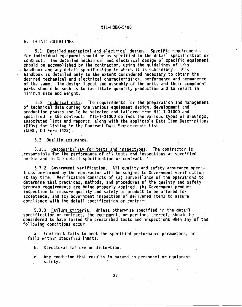
MIL-HDBK-5400
5. DETAIL GUIDELINES
5.1 .. Detailed mechanical and electrical design. Specific requirements for individual equipment should be as specified in the detail specification or contract. The detailed mechanical and electrical design of specific·equipment should be accomplished by the contractor, using the guidelines of this handbook and any detail specification to which it is subsidiary. This handbook is deta.iled only to the extent considered necessary to obtain the desired mechanical and electrical characteristics, performance and permanence of the same. The design layout and assembly of the units and their component parts should be such as to facilitate quantity production and to result in minimum size and weight.
5.2 Technical data. The requirements for the preparation and management of technical data during the various equipment design, development and production phases should be selected and tailored from MIL-T-31000 and specified in ttie contract. MIL-T -31000 deffnes the various types of drawings, associ·ated.lists and reports, along .with the applicable Data Item Descriptions (OIOs) for·listing in the Contract Data Requirements List · (CDRL, OD Form 1423~.
. )
5.3 Quality assurance.
5.3.1 ResponsibilitY for tests and inspections. The contractor is .responsible for the performance of all tests and inspections as specified herein and in the detail specification or contract. ·
5.3.2 Government verification. All quality and safety assurance operations performe.d by· the contractor will be subje~t to Government verification at any time. Verification·consists of {a) surveillance of the ope~ations to determine that practices, methods, and procedures of the quality and safety program requirements are being properly applied, (b) Government product inspection to measure quality and safety of product to be offered for acceptance, and (c) .Government inspection of delivered items to asiure compliance with the detail specification or ~ontract.
5.3.3 Failure criteria. Unless otherwise specified in the detail specification or contract, the equipment, or portions thereof, should be considered to have failed the prescribed· tests and inspections when any of the following conditions occur:
a. Equipment fails to meet the specified performance parameters, or fails within specified limits.
b. Structural failure or distortion.
c. Any condition that results in hazard to personnel or equipment ~afety.
37

MIL-HDBK-5400
d. Process control deficiencies.
e. ·Inspection and test procedure deficiencies.
f. Improper labeling, handling and packaging.
5.3.4 Problem/failure reporting and corrective· action. Problem/failure reporting and corrective action of any failure occurring as a result of tests performed during incoming inspection should be specified in the contract or detail soecification. In addition. ~ reoort deoictinq the Yield or percentage of failures that. occurred for each-level' of hardware should. be specified inthe contract or detail specification. For correction and consideration, a Government-Industry Data Exchange Program (GIDEP) should be established and specified in the contract or detail specification.
5;3.5 Design gualifjcation tests. Design qualification testing should be performed prior to commitment to production. The requirements for design qualification of the equipment, to demonstrate that it conforms to specified performance and reliabili~y requirements under specified combined environmenta\1 conditions, should be cited in the contract or detail specification. The requirements for environmental stress screening (ESS), to detect and correct latent manufacturing defects before the initiat~on of reliability accounting tests and applied in conjunction with the design
·qualification requirements,.·should be specified in the contract or detail ·specification. These tasks identify the details to be specified by the acquisition activity and the applicable Data Item Description· (D!Ds) for incorporation into the CDRL (DO Form 1423). Refer to MIL-STD-2218 ·for guidance on thermal design verification tests.
5.3.6 Fjrst article tests. The first .article tests· should be performed in conjunction with production contracts only. The requirement for the performance of first article tests should be specified in the detail specification or contract. First article tests are those tests to be performed on one (1) or more equipments (as required by the detail specification or contract) representative of production equipment to be supplied on contract or order.
5.3.6.1 Scope of tests. The requirement for first article tests should include all tests deemed necessary by the acquiring activity to determine that the equipment meets all of the ,requirements specified in the detai.l specification or contract. These tests should in~lude environmental tests in accordance with ·the test methods and procedures of MIL-STD-810. · Electromagnetic interference tests and test methods should be in accordance with Mll-STD-461.
5.3.7 Quality conformance tests. The requirement for the performance of quality conformance tests s·nau1d ·be specified in the detail specification or contract. Quality conformance tests are those tests deemed necessary to determine that the equipments submitted for acceptance under the contract are
38

MIL-HDBK-5400
equivalent in performance and construction to the approved first article .equipment. Quality conformance tests should consist of the following:
a. Individual tests to be performed on each equipment submitted for acceptance under the contract. These tests should include environmental stress.screening (ESS) or burn-in ..
b. Production reliability acceptance tests, to determine that ptoduction equipment continues to conform to performance and reliability requirements under specific environmental conditions, should be specified in the contract or detail specification. Production reliability acceptance tests identify thos~·details to be specified by the acquisition activity, including test plan, sampling plan, environmental test conditions, performance requirements, and the applicable Data Item Descriptions. (D!Ds) for incorporation into the CDRL (DO Form 1423).
5.'4 Preparation for del jvery. Requirements for packaging, p·acking and marking for shipment of equipment should be specified in the detail specification or contract.
' 6. NOTES
(This section· contains information of a general or explanatory nature which .may be helpful, but is not mandatory.) :
6.1 Intended use. This handbook is intended as a general design guide for use in the development and preparation of detail specifications and contracts for airborne electronic equipment to specify those requirements .applicable to the specific equipment.
6.2 Details for jn~ion in equipment specifications and contracts. Since this handbook only provides·guidance; the detail specification (as prepared either by the Government, the ·equipment manufacturer for the Government, or the prime vehicle contracto.r) or contract must specify actual requirements from the multiple choices, tailoring, or exceptions available in the following paragraphs:
·a. Classification requirements (see 1.2, 1.2.1).
b. Tailoring requirements (see 1.1.2 and Appendix B).
c. Warmup time-(see 4.2.8.1).
d. Electromagnetic interference characteri st'i cs (see 4. 2. 9).
e. Electrostatic discharge control. program (see 4.2.10).
39

MIL-HDBK-5400
f. Human engineering requirements (see 4.2.14}.
g. Maintainability program requirements (see 4.2.16}.
h. Equipment orientation (see 4.2.22).
i. Pressure and altitude requirements for specifying air leakage (see 4.2.24(g) and. (h)).
j. Reliability program requirements (see 4.2.25}.
k. Repairability requirements (see 4.2.26}.
1. System safety program requirements (see 4.2.27.1}.
m. Testability program requirements {see 4.2.29}.
n. ·Thermal design requirements (see 4.2.30. and 4.2.30.1}.
o. Spe~ial tools (see 4.2.31.2).
p. Parts control program requirements and GFB (see 4.3.~ thru 4.3.3).
q. Samples for nonstandard parts and material approval, if required.
r. Nonstandard material approval (see 4.4.4.1).
s. Environmental test methods, procedures, limits, etc. (see 4.6 thru 4.6.2.10).
t. Detail equipment design (see 5.1).
" Uo Technical data (see 5.2).
v. Equipment design qualification tests (see 5.3.5}.
w. First article tests and sample (see 5.3.6, 5.3.6.1).
x. Accessory material and data to perform tests, if required.
y. Quality conformance requirements and tests (see 5.3.7}.
z. Packaging requirements (see 5.4).
6.3 Use of helium. Helium should not be used as a pressur1z1ng gas in sealed units containing electron tubes. When it is necessary to use helium for leak detection purposes, exposure should be limited to .the time necessary fo.r the test, followed hy thorough purging. ·
40

MIL-HDBK-5400
6.4 Publications. In the design of electronic equipment, consideration should be·given to the information contained in the following publication:
a. Handbook, Preferred Circuits Navy Aeronautical Electronic NAVAJR-16-1-519, Vnlume 2 Equipment.
6.5 Subject term...l_krrwordJ listing.
,-
Classification Design and construction Environmental requirements Material selection Military standard Parts selection Processes and finishes Tailoring requirements
Custodians: Army-CR -- . Navy-AS Air Force-11
Reviewer activities: Army- Ml, AR, AV Navy '':: ,-_,EC Air 'Force - 15, ·17. OLA - ES
•' -·
99
41
Preparing activity: Navy - AS
(Project GDRQ-0164)
; :

!0. SCOPE
MIL-HDBK-5400
APPENDIX A
APPLICABLE DOCUMENTS
10.1 Scope. THIS APPENDIX IS NOT A MANDATORY PART OF THIS HANDBOOK. THE INFORHATION CONTAINED HEREIN IS INTENDED FOR GUIDANCE.
10.2 This ·appendix lists specifications, standards, handbooks and other publications selected fnr their applicability in the design and construction of airborne electronic equipment. Those parts and materials covered by documents listed in this appendix will be considered standard items. When part selection standards a~~ referenced, the doctJments listed in the selection standard have the same status as those listed directly in this appendix and the parts they cover are also considere~ standard (unless otherwise restricted or banned for airborne applications).
10.3 Selection of dOC!!mefltS for nonstandard parts and materials. When Appendix A does not provide a document suitable for the design requirement, selection of specifications and standards for nonstandard parts and materials should be specified by the r.ontracting or design activity, unless otherwise cited herein or in the referenced MlL-HDBK-454 guidelines.
20. APPLICABLE DOCUMENTS
20.1 The documents listed in this appendix are applicable to the extent specified directly herein nr in the referenced M!L-HDBK-454 guidelines.
20.2 iii?Plicable issue~. Unless otherwise specified, the issues of these docttments are those listed in the issue of the Department of Defense Index of Specifications and Standards (DODISS) and supplement thereto, cited in the. soli~itation. Later revisions, amendments and docume~ts superseding those listed in Appendix A may be used when preferred by the contractor. When a later isstJe is used, all applicable requirements of the later revision should be used.
20.3 CoQj~. Unle~s nthen~ise indicated, copies of federal and military sper.ifications, standards "nd hanrlbooks are available from the Standardization Document Order Desk, 700 Robbins Avenue, Building 4D, Philadelphia, PA 19111-5094. Addresses for orrlering copies of non-government documents are listed on the following page.
A-I

MJL-HOBK-5400
APPENDIX A
30. APPLICATION OF SELECTED DOCUMENTS
30. l It is not the intent that all documents listed in this appendix apply to all contracts, or that those that do apply necessarily apply in full. Before proceeding with the app 1 icat ion of any document, all contractua 1 specifications and requirements should be reviewed by the contractor, and the extent of applicability to the specific equipment design be determined.
Industry Association Adrlresses. Addresses for obtaining copies of nongovernment industry association documents are as follows:
AGMA Americ?.n Gear f1anufacturers' Association 1500 King Street, Suite 201 Alexandria, VA 22314
AMS Society of A11tomotive Engineers, Inc. (SA£) 400 Commonwealth Drive Warrenda 1 e, PA I 5096
ANSI American flational Standards Institute 11 West 42nd Street · New York, !IY 10036
ASM American Society for Metals Metals Park, OH 44073
ASTM American Society for Testing and Materials 1916 RJr.e Street Philad2lphia, PA 19103
AWS American ~!~lding Society 550 NW LeJ~une Road f1i ami , Fl 33126
ElA El ectrnnir. l nrlustri es Associ at ion 2500 Wilson Blvd Arlington, VA 22201
IEEE lnstitlite nf Electrical and Electronics Engineers 445 Ho,~s Lane, P.O. Box 1331 Piscataway, HJ 08855-1331
IPC Institute for Interconnecting and Packaging Electronic Circuits 7380 North Lincoln Avenue lincolnwood, ·1L 60646-1776
A-2

MIL-HDBK-5400
APPENDIX A
NAS National Standards Association 1200 Quince Orchard Boulevard Gaithersburg, MD 2087B
NFPA National Fire Protection Association Battery March Park Q11incy, MA 02269
UL Underwriters Laboratories, Inc. 333 Pfingsten Road Northbrook, IL 60062-2096
FEDERAL SPECIFICATIONS
A-A-52401
A-A-52414
A-A-554B5
L-P-516
V-T-285
V-T-295
FF-B-171
FF-B-187
FF-B-575
FF-N-836
FF-R-556
FF-S-85
FF-S-86
FF-S-92
Bea1·ing, Sleeve (Steel-Backed)
Bearing, Roller, Thrust
Pads, Electrical-Electronic Component, General · Requirements for
Pla:;tic Sheet' and Plastic Rod, Thermosetting, Cast
Thread, Polyester
ThrPad, Nylon
Rea•·inl)~. Ball, Annular (General Purpose)
Beal·i nl), Ro 11 er, Tapered
Bolts, llexagon and Square
Nut, Square, Hexagon, Cap, Slotted,.Castle Knurled, Welrling and Single Ball Seat
RivP.t, Solid, Small; Rivet, Split, Small; Rivet Tubular, Small; Flat Washer (B11rr); and Cap, Rivet, General Purpose
ScrPw, Cap, Slotted and Hexagon-Head
Screw, Cap, Socket-Head
Screw, Machine; Slotted, Cross Recessed or Hexagon Head
A-3

FF-S-200
FF-S-210
FF-W-84
FF-W-92
FF-W-100
QQ-C-320
QQ-N-290
QQ-P-416
TT-S-1732
VV-l-800
VV-P-236
ZZ-R-765
CCC-C-428
MMM-A-121
MMM-A-130
MMM-A-132
MMM-A-134
MMM-A-138
Mil-HDBK-5400
APPENDIX A
Setscrews; Hexagon Socket and Spline Socket, Headless
Setscrews, Square Head (Inch) and Slotted Headless (Inch & Metric)
Washers, Lock (Spring)
Washer, Flat (Plain)
Washer, lock (Tooth)
Chromium Plati-ng (Electrodeposited)
Nickel Plating (Electrodeposited)
Plating, Cadmium (Electrodeposited)
Sealing Compound, Pipe Joint and Thread, lead Free, Genera 1 Purpose
lubricating Oil, General Purpose, Preservative (WaterDis,,lar.ing, Low-Temperature)
Petrolatum, Technical
Rubher, Silicone
Cloth, Duck, Cotton; Fire, Water, Weather and MildewResistant
Adhesive, Bonding, Vulcanized Synthetic Rubber to Steel
Adhesive, Contact
Adhesive, Heat Resistant, Airframe Structural, Metal to Metal
Adhesive, Epoxy Resin, Metal to Metal Structural Bonding
Adhesive, Metal to Wood, Structural
A-4

MMM-A-181
MMM-A.-189
MMM-A-1617
MMM-A-1931
MIL-HDBK-5400
APPENDIX A
Adhesive, Phenol, Resorcinol, or Melamine Base
Adhesive, Synthetic-Rubber, Thermoplastic, General Purrose
Adhesive, Rubber Base, ~eneral Purpose
Adhesive, Epoxy, Silver Filled, Conductive
MILITARY SPECIFICATIONS
MIL-I-10
MIL-M-14
MIL-C-17
MIL-S-61
MIL-T-152
MIL-C-172
MI L-V-173
MIL-W-530
MIL-C-572
MlL-I-631
MIL-J-641
MIL-P-642
MIL-T-713
Insulating Compound, Electrical, Ceramic, Class L
Molrling Compounds, Thermosetting
Cable, Radio Frequency, Flexible and Semirigid, General Specification for
Shunts, Instrument, External, 50 Millivolt (Lightweight Type)
Treatment, Moisture and Fungus Resistant, of Communications, Electronic and Associated Electrical Equipment
Cases, Bases, Mounting and Mounts, Vibration (For Use With Electronic Equipment in Aircraft)
Varnish, Moisture and Fungus Resistant (For Treatment of Communications, Electronic and Associated Equipment)
Webbing, Textile, Cotton, General Purpose, Natural or in Colors
Corns, Yarns and Monofilaments, Organic Synthetic Fiber
Insulation, Electrical, Synthetic-Resin Composition, Nonrigid
Jack, Telephone, General Specification for
Plug, Telephone anrl Accessory Screws, General Specification for
Twine, Fibrous: Impregnated, Lacing and Tying
A-5

MIL-S-1222
MIL-1-1361
1·11L-L-2105
IHL-L-3150
MIL-1-3158
MIL-1-3190
MIL- T-3530
1111.- L -366 I
Mll-l-3825
MIL-L-3890
MIL-L-3918
M!L-A-3920
MIL-B-3990
MIL-W-4088
MIL-S-5002
MIL-L-5057
11 I L- B-5087
t-\IL-W-5088
MIL-HDBK-5400
APPENDIX A
Studs, Bolts, Hex Cap Screws, Socket Head Cap Screws and Nuts
Instrument Auxiliaries, Electrical Measuring: Shunts, Resistnrs and Transformers
Lubric~ting Oil, Gear, Multi-Purpose (Metric)
Lubricating Oil, Preservative, Medium
Insulation Tape, Electrical Glass-Fiber (Resin Filled); and Cord, Fibrous-Glass
Insulation Sleeving, Electrical, Flexible, Coated, General Specification for
Thread and Twine, Mildew Resistant or Water Repellant Treater!
Lamrhnlders, Indicator Lights, Indicator-Light Housings, and Indicator-Light Lenses, General Specification for
Insulation Tape, Electrical, Self-Fusing:· For Use in Electronics, Communications and Allied Equipment
Lines, Radio Frequency Transmission (Coaxial, Air Dielec1 ric)
Lubricating Oil, Instrument, Jewel Bearing
Adhesive, Optical, Thermosetting
Bearings, Roller, Needle, Airframe, !Inti- Friction, Inch
Webbings, Textile, Woven Nylon
Surface Treatments and Inorganic Coatings for Metal Surfaces of Weapons Systems
Lights, Instrument, Individual, General Specification for
Bondin~. Electrical and Lightning Protection, for Aerospoce Systems
Wiring, Aerospace Vehicle
A-6

MIL-H-5440
MIL-A-5540
MIL-C-5541
MIL-F-5591
MIL-R-5674
MIL-B-5687
MIL-L-6085
MIL-L-6086
MIL-1.-6363
MIL-C-6781
MIL-B-6812
MIL-W-6858
MIL-J-7444
MIL-S-7742
MIL-P-7788
MIL-M-7793
MIL-B-7838
MIL-HDBK-5400
APPENDIX A
Hydrau1ic Systems, Aircraft, Design and Installation Req11irements for
Adhn.sive, Polychloroprene
Chemical Conversion Coatings on Aluminum and Aluminum Alloys
FastenP.rs, Panel; Nonstructural
Rivets, Structural, Aluminum Alloy, Titanium Columbium A1loy, General Specification for
Bearings, Sleeve, Washers, Thrust, Sintered, Metal Powder Oi 1 Impregnated, Genera 1 Specification for
Lubricating Oil, Instrument, Aircraft, Low Volatility
Luhricating Oil, Gear, Petroleum Base
Lamps, Incandescent, Aircraft Service, General Sper.ification for
Control Panel, Aircraft Equipment, Rack or Console Mounterl
Bolts, Aircraft
Weldinq, Resistance, Spot and Seam
Insulation Sleeving, E1ectrical, Flexible
Screw Threads, Standard, Optimum Selected Series; General Specification for
Panels, Information, Integrally Illuminated
Meter, Time Totalizing
Bolt, Internal Wrenching, 160 KSI FTU
A-7

HIL-B-7883
MIL-R-7885
MIL-T-7928
MIL-S-7947
HIL-L-7961
MIL-M-7969
MIL-S-8516
MIL-A-8576
MIL-H-8609
MIL-A-8625
MIL-H-8810
MIL-R-8814
11!L-B-Il83l
Hll-S-8879
HIL-11-8891
MIL-W-8939
MIL-B-8942
MIL-B-8943
f11L-HDBK-5400
APPENDIX A
Brazing of Steels, Copper, Copper Alloys, 'Nickel Alloys, Aluminum and Aluminum Alloys
Rivets; Blind, StrtJctural, Mechanically Locked Spindle and Friction Lockert Spindle, General Specification for
Terminal, Lug Splices Conductor, Crimp Style, Copper, General Specification for
Steel, Sheet and Strip (1095) Aircraft Qttality
Li(l•lts, Indicators, Press to Test
Hotnr, Alternating Current, 400 Cycle, 115/200-Volt System, Aircraft, General Specification for
Seal in!) Compound, Polysulfide Rubber, Electric Connectors and El<:ctric Systems, Chemically Cured
Adhr~sive, Acryli~ Base, for Acrylic Plastic
Hotors, Direct Current, 28 Volt System, Aircraft, General Specification for
Anodic: Coatings, for Aluminum and Aluminum Alloys
Handles, Control, Aircraft
Rivets, Blind, Nonstruct11ral Type
Boi r:, i80 KSi FTU and iOB KSi FSU, 4!>Uu~. Protruding and Flush !lead, General Specification for
Screw Threads, Controlled Radius Root With Increased Hinnr fliameter, General Specification for
Hydraulic Systems, Manned Flight Vehicles, Type III, Oesign, Installation, and Data Requirements for, General Sper.ification for
Weldin~!. Resistance, Electronic Circuit Modules
Bearings, Plain, TFE Lined, Self-Aligning
Bearin~s, Journal Plain and Flanged, TFE Lined
A-8.
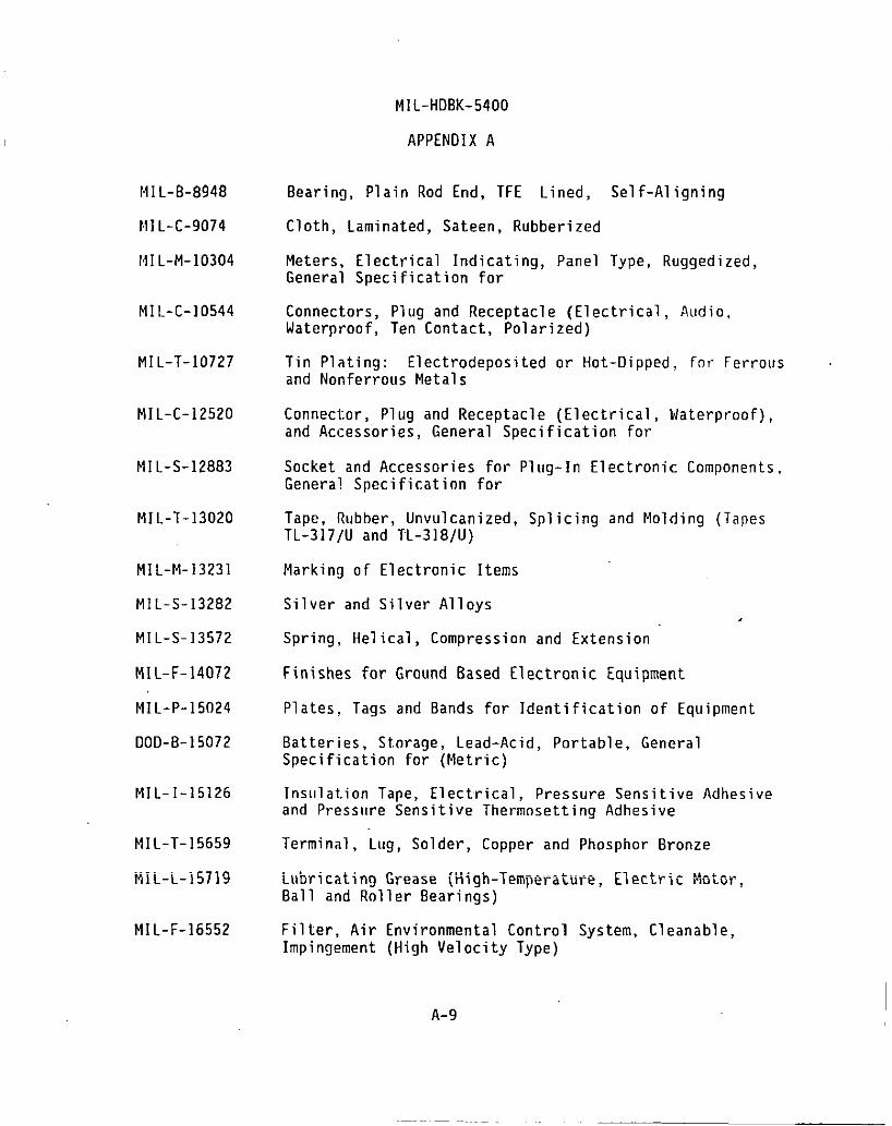
~m-B-8948
f.1I L-C-9074
1·11L -M-1 0304
MIL-C-10544
MIL-T-10727
MIL-C-12520
MIL-S-12883
MIL-T-13020
MIL-M-13231
MIL-S-13282
MIL-S-13572
MI L-F- 14072
MIL-P-15024
DOD-B-15072
MIL-1-15126
MIL-T-15659
Mil-L-15719
MIL-F-16552
M1L-HDBK-5400
APPENDIX A
Bearing, Plain Rod End, TFE Lined, Self-Aligning
Cloth, Laminated, Sateen, Rubberized
Meters, Electrical Indicating, Panel Type, Ruggedized, General Specification for
Connectors, Plug and Receptacle (Electrical, Audio, Waterproof, Ten Contact, Polarized)
Tin Plating: Electrodeposited or Hot-Dipped, for Ferrous and Nonferrous Metals
Connector, Plug and Receptacle (Electrical, Waterproof), and Accessories, General Specification for
Socket and Accessories for Plug-In Electronic Components, General Specification for
Tape, Rubber, Unvulcanized, Splicing and Molding (Tapes TL-317/U and TL-318/U)
Marking of Electronic Items
Silver and Silver Alloys
Spring, Helical, Compression and Extension
Finishes for Ground Based Electronic Equipment
Plates, Tags and Bands for Identification of Equipment
Batteries, Storage, Lead-Acid, Portable, General Specification for (Metric)
Insulation Tape, Electrical, Pressure Sensitive Adhesive and Pressttre Sensitive Thermosetting Adhesive
Terminal, Lug, Solder, Copper and Phosphor Bronze
Lubricating Grease (High-Temperature, Electric f·1otor, Ball and Roller Bearings)
Filter, Air Environmental Control System, Cleanable, Impingement (High Velocity Type)
A-9
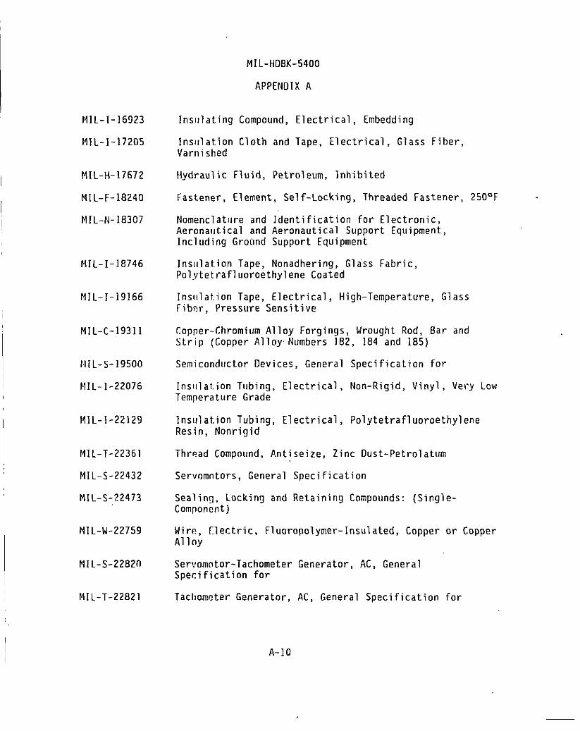
Mll-1-16923
MJ L-1-17205
MIL-H-17672
Mll-F-18240
fHl-N-18307
Mll-i-18746
f11l-i-19166
Mll-C-19311
rHl-S-19500
~11l-i-22076
MIL-J-22129
Mll-T-22361
Mll-S-22432
Mll-S-22473
Mll-W-22759
Mll-S-22820
Mll-T-22821
Mll-HDBK-5400
APPENDIX A
Insulating Compound, Electrical, Embedding
Insulation Cloth and Tape, Electrical, Glass Fiber, Varnished
Hydraulic Fluid, Petroleum, Inhibited
Fastener, Element, Self-Locking, Threaded Fastener, 250°F
Nomenclat11re and Identification for Electronic, Aerona11tical and Aeronautical Support Equipment, Including Groond Support Equipment
Insulation Tape, Nonadhering, Glass Fabric, Polytetrafluoroethylene Coated
Insulation Tape, Electrical, High-Temperature, Glass Fiber, Pressure Sensitive
Copper-Chromium Alloy Forgings, Wrought Rod, Bar and Strip (Copper Alloy Numbers 182, 184 and 185)
Semiconductor Devices, General Specification for
Insulation Tubing, Electrical, Non-Rigid, Vinyl, Very low Temperature Grade
lnsiJlation Tubing, Electrical, Polytetrafluoroethylene Resin, Nonrigid
Thread Compound, Antiseize, Zinc Dust-Petrolatum
Servomotors, General Specification
Sealing, Locking and Retaining Compounds: (SingleComponent)
Wire, [lectric, Fluoropolymer-lnsulated, Copper or Copper Alloy
Servomotor-Tachometer Generator, AC, General Specification for
Tacl1ometer Generator, AC, General Specification for
A-10

MIL-C-22931
MIL-F-22978
MIL-1-23053
MIL -B-23071
MIL-S-23190
MIL-1-23264
MIL-L-23398
MIL-S-23586
MIL-1-23594
MIL-T-23648
MIL-C-23806
MIL-G-23827
~11 L-M-2404 i
MIL-1-24092
MIL-G-24139
MIL-A-24179
MIL-l-24204
MIL-HDBK-5400
APPENDIX A
Cable, Radio Frequency, Semirigid, Coaxial, Semi-Air Dielectric, General Specification for
Fastenr.r, Rotary, Quick-Operating, High Strength
Insulation -Sleeving, Electrical, Heat Shrinkable, General Sper.ification for
Blowers, Miniature, for Cooling Electronic Equipment, General Specification for
Strops, Clamps, and Mounting Hardware, Plastic and Metal for Cahle Harness Tying and Support
Insttla1ors, Ceramic, Electrical and Electronic, General Specification for
Lttbric~nt, Solid Film, Air Cured, Corrosion Inhibiting, NATO Cnde Number S-749
Seal in'] Compound, "Electrical, Silicone Rubber, Aecelet~ator Required
Insulation Tape, Electrical; High Temperature Polytetraflttoroethylene, Pressure-Sensitive
Thermistor (Thermally Sensitive Resistor), Insulated, General Specification for
Cable, Radio Frequency, Coaxial, Semirigid, Foam n~~ln~\·~~~ ~nnn~~l ~nn~~~~r~+~nn ~n~ Ult:lt:"l...~l 11..., \ll;;ll't:IQI . ..1!-''C"-11 II...GL.IUII lVI
Grease, Aircraft and Instrument, Gear and Actuator Screw
r-\oldinq and Potting Compound, Chemically Cured, Polvur~>thane
Insulal.ing Varnishes and Solventless Resins for llppl ic:,tion by the Dip Process
Gre"se, f·lulti-Purpose, Water Resistant
Adhnsi•!e, Flexible Unicellular-Plastic Thermal Insulation
Insttlalion, Electrical, High Temperature, Bonded, Synthetic Fiber Paper
A-ll

/HL-G-24211
MIL-R-24243
MIL-S-24251
MIL-I-24391
DOD-G-24508
MIL-l-24768/]
Mll-1-24768/2
MIL-I-24768/3
MIL-l-24768/7
Mll-1-24768/8
HIL-1-24768/9
Mil- 1-24768/10
MIL-I-2476fl/ll
Mll-1-24768/12
MIL-HDBK-5400
APPENDIX A
Gaskets, Waveguide Flange, General Specification for
Rivet, Blind, Nonstructural, Retained Mandrel, General Specification for
Shields, Retainer (Bases), and Adapters, Electron Tube, Heat Dissipating, General Specification for
Insulation Tape, Electrical, Plastic, Pressure Sensitive
Grease, High Performance, Hulti-Purpose (Metric)
Insulation, Plastic, Laminated, Thermosetting, GlassCloth, Helamine-Resin (GHE)
Insula! ion, Plastic, Laminated, Thermosetting, GlassCloth, Epoxy-Resin (GEE)
Insulat.ion, Plastic, Laminated, Thermosetting, GlassCloth, Epoxy-Resin (GEB)
Insulation, Plastic, Laminated, Thermosetting, GlassCloth, Polytetrafluoroethylene-Resin (GTE)
Insttlation, Plastic, Laminated, Thermosetting, GlassCloth, Melamine-Resin (GMG)
Insulation, Plastic, Laminated, Thermosetting, NylonFabric-Base, Phenolic-Resin (NPG)
Insulation, Plastic, Laminated, Thermosetting, Paper-Base, Phenolic-Resin (PBE)
Insulation, Plastic, laminated, Thermosetting, Paper-Base, Phenolic-Resin (PBG)
Insulation, Plastic, Laminated, Thermosetting, Paper-Base, Phenolic-Resin (PBM)
MIL-I-24768/1~ Insulation, Plastic, Laminated, Thermosetting, CottonFabric-Base, Phenolic-Resin (FBE)
Mll-I-24768fl4 Insulation, Plastic, Laminated, Thermosetting, CottonFabric-Base, Phenolic-Resin (FBG)
MIL-I-24768/16 Insulation, Plastic, Laminated, Thermosetting, CottonFabric-Base, Phenolic-Resin (FBM)
A-12
--·-------------

MIL-HDBK-5400
APPENDIX A
MIL-1-24768/17 Insulation, Plastic, Laminated, Thermosetting, GlassCloth, Silicone-Resin (GSG)
MIL-N-25027 Nut, SP.lf-Locking, 250°F, 450°F and 800°F
MIL-K-25049 Knobs, Control, Electronic Equipment, General Specification for
MIL-A-25463 Adhesive, Film Form, Metallic Structural Sandwich Construction
MIL-L-25467 Lighting, J"ntegral, Aircraft Instrument, General Specification for
MIL-P-25518 Plasti( Material, Silicone Resin, Glass Fiber Base, LowPressttre Laminated
MIL-L-27160 Lighting, Instrument, Integral, White, General Specification for
MIL-W-27265 Webbin~. Textile; Woven Nylon, Impregnated
MIL-R-27384 Rivet, Blind, Drive Type
MIL-C-27500
MIL-D-28728
MIL-M-28787
MIL-D-28803
MIL-P-29590
MIL-T-31000
MIL-M-38510
Cable, Power, Electrical and Cable Special Purpose, Shielded and Unshielded, Electrical, General Specification for
Dial, Control, Multi-Turn Counters, General Specification for
f1odules, Standarc(Electronic, General Specification for
Display Optoelectric, Readouts, Blacklighted Segmented, Genera·l Srecification for
Power Suprlies, Airborne, Electronic, General Specification for
Technical Data Pa(kages, General Specification for
Microcircuits, General Specification for (Inactive)
A-13

MIL-HDBK-5400
APPENDIX A
"' MIL-PRF-38534 Hybrid Microcircuits, General Specification for
MIL-PRF-38535 Integrated Circuits (Microcircuits) Man11facturing, General Specification for
MIL-C-39006/22 Capacitors, Fixed, Electrolytic (Nonsolid Electrolyte) Tantal11m (Polarized, Sintered Slug), 85°C (Voltage Derated to !25°C), Established Reliability, Style CLR79
MIL-C-39006/25 Capacitors, Fixed, Electrolytic (Nonsol id Electrolyte), Tantalum (Polat;ized, Sintered Slug) (Extended Range), 85°C (Voltage Derated to l25°C), Established Reliability, Style CLR8l
MIL-T-43435 Tap~. Lacing and Tying
MIL-G-45204 Golrl Plating, Electrodeposited
MIL-L-46010 Lubricant, Solid Film, Heat Cured, Corrosion Inhibiting
MIL-S-46049 Strip, Metal, Carbon-Steel, Cold Rolled, Hardened and Temrererl, Spring Quality
MIL-A-46050 Adhesive, Cyanoacrylate, Rapid Room-Temperature Curing, Solventless
MIL-I-46058 Insulating Compound, Electrical (for Coating Printed Cir~11it Assemblies)
MIL-P-46112 Plasti~ Sheet and Strip, Polyimide
MIL-A-46146 Adhesive-Sealants, Silicone, RTV, Non-Corrosive (For Use With Sensitive Metals ann Equipment)
MIL-S-46163
MIL-1-46852
tilL -11-4 7315
SealinQ, Lubricating and Wicking Compounds: Thread Lockin~. Anaerobic, Single Component
Insulation Tape, Electrical, Self-Adhering, Unsupported Silicone Rubber
Adhesive, Polyurethane
A-14

Hll-A-47318
M!L-A-486!!
Mil-B-49030
Mil-B-49430
MIL-B-49436
Mll-1-49456
Mll-B-49458
Mll-R-50781
Mil-A-52194
MIL-S-55041
ml-C-55116
1·1Il-B-55130
rm- T-55156
Mil-T-55164
MIL-C-55181
MIL-0-55310
MIL-A-55339
Mil-T-55631
MIL-C-81021
Mll-HDBK-5400
APPENDIX A
Adhesive, Copolymer Polyurethane
Adhesive System; Epoxy-E1astomeric; for Glass-To-Metal
Batteries, Dry (Alkaline)
Batteries, Non-Rechargeable, Lithium Sulfur DiJxide
Batteries, Rechargeable, Nickel-Cadmium, Sealed
Insulation Sheet, Electrical, Silicone Rubber, Thermally Conciuct:t ve, Fi berg] ass Reinforced
Batteries, Non-Rechargeable, lithium Manganese Dioxide
Resolver, Electrical, Linear, General Specification for
Adhesi':e, Epoxy (for Bonding Glass Reinforced Polyester)
Switches, Waveg11ide, General Specification for
Connectors, Miniature, Audio, Five-Pin and Six-Pin, Genera·r Specification for
Batteries, Rechargeable, Nickel-Cadmium, Sealed
Termin~ls, lug, Splices, Conductor; Screw Type, General Specification for
Terminal Boards, Molded, Barrier, Screw and St11d Types, and Associated Accessories, General Specifi~ation for
Connectors, Plug and Receptacle, Intermediate Power (Electrical, Waterproof) Type MW, General Specification for
Oscillator, Crystal Controlled, General Specification for
Adapters, Connector, Coaxial, Radio Frequency (Between Series and Within Series), General Specification for
Transformers, Intermediate Frequency, Radio Frequency and Discriminator, General Specification for
Copper-Beryll i urn Alloy (Copper Alloy Numbers Cl7500 and C17510), Strip
A-!5

MIL-W-81044
MIL-A-81236
MIL-A-81253
MIL-M-81288
MIL-G-81~22
~liL-L-81329
r11L-E-81512
f·liL-I-81550
MIL-B-81744
MIL-S-81746
MIL-B-81757
MIL-1-81765
MIL-C-81774
MIL-B-81793
MlL-B-81934
MIL-B-81936
MIL-S-81963
MIL-A-83377
MIL-HDBK-5400
APPENDIX A
Wire, Electric, Crosslinked Polyalkene, Crosslinked Alkane-imide Polymer, or Polyarylene Insulated, Copper or Copper Alloy
AdhP.sive, Epox.v Resin With Polyamide Curing Agent
Adhesive, Epoxy Resin With Polyamine Curing Agent
Mounting Bases, Flexible Plastic Foam
Grease, Aircraft, General Purpose, Wide Temperature Range
Lubricant, Solid Film, Extreme Environment, NATO Code Numher S-1737
Encoder, Shaft Position to Digital, Contact Type, Altitude Reporting, General Specification for
lnsttlating Compound, Electrical, Embedding, Reversion Resistant Silicone
Barrier Coating Solution, Lubricant Migration Deterring
Servtorqs, General Specification for
Batteries and Cells, Storage, Nickel-Cadmium, Aircraft, General Specification for
Insulating Components, Molded, Electrical, Heat Shrinkable, General Specification for
Control Panel, Aircraft, General Requirements for
Bearin~s. Ball, Annular, for Instruments and Precision Rotating Components
Bearin~s, Sleeve, Plain and Flanged, Self-Lubricating, General Specification for
Bearing, Plain, Self-Aligning (BeCu Ball, CRES·Race), General Specification for
Servo Components, Precision Instrument, Rotating, Common Requirements and Tests, General Specification for
Adhesive Bonding (Structural) for Aerospace and Other Systems, Requirements for
A-16

MIL-S-83502
MIL-C-83503
MIL-R-83516
MIL-T-83721
MIL-S-83731
MIL-S-83734
HIL-B-83769
MIL-1-85080
MIL-E-85082
MIL-R-85725
MIL-E-85726
111 L-L-85762
MIL-A-87135
MIL-D-87157
FEDf.RAL STANDARDS
rEO-STO-H28
FED-STD-595
MJL-HDBK-5400
APPENDIX A
Sockets, Plug-In Electronic Components, Round Style, General Specification for
Connectors, Electrical, Flat Cable, andjor Printed Wiring Board, Nonenvironmental, General Specification for
Relays, Reed, Dry, General Specification for
Transformers, Variable, Power, General Specification for
Switch, Toggle, Unsealed and Sealed Toggle, General Specification for
Sockets, Plug-In Electronic Components, Dual-in-Line Packages (DIPS) and Single-in-Line Packages (SIPs), General Specification for
Batteries, Storage, Lead-Acid, General Specification for
Jnsttlation Sleeving, Electrical, Shrinkable Without Heat, General Specification for
Encoders, Shaft Angle to Digital, General Specification for
Rack, Integrated Avionics, Forced Air Cooled, General Specification for
Enclosure, Standard Avionics, Forced Air Cooled, General Specification for
Lighting, Aircraft, Interior, Night Vision Imaging System (NVIS) Compatible, General Specification for
Adhesives, Non-Conduitive, for Electronics Application
Displays, Diode, Light Emitting, Solid State, General Specification for
Screw-Thread Standards for Federal Services
Colors Used in Government Procurement
A-17
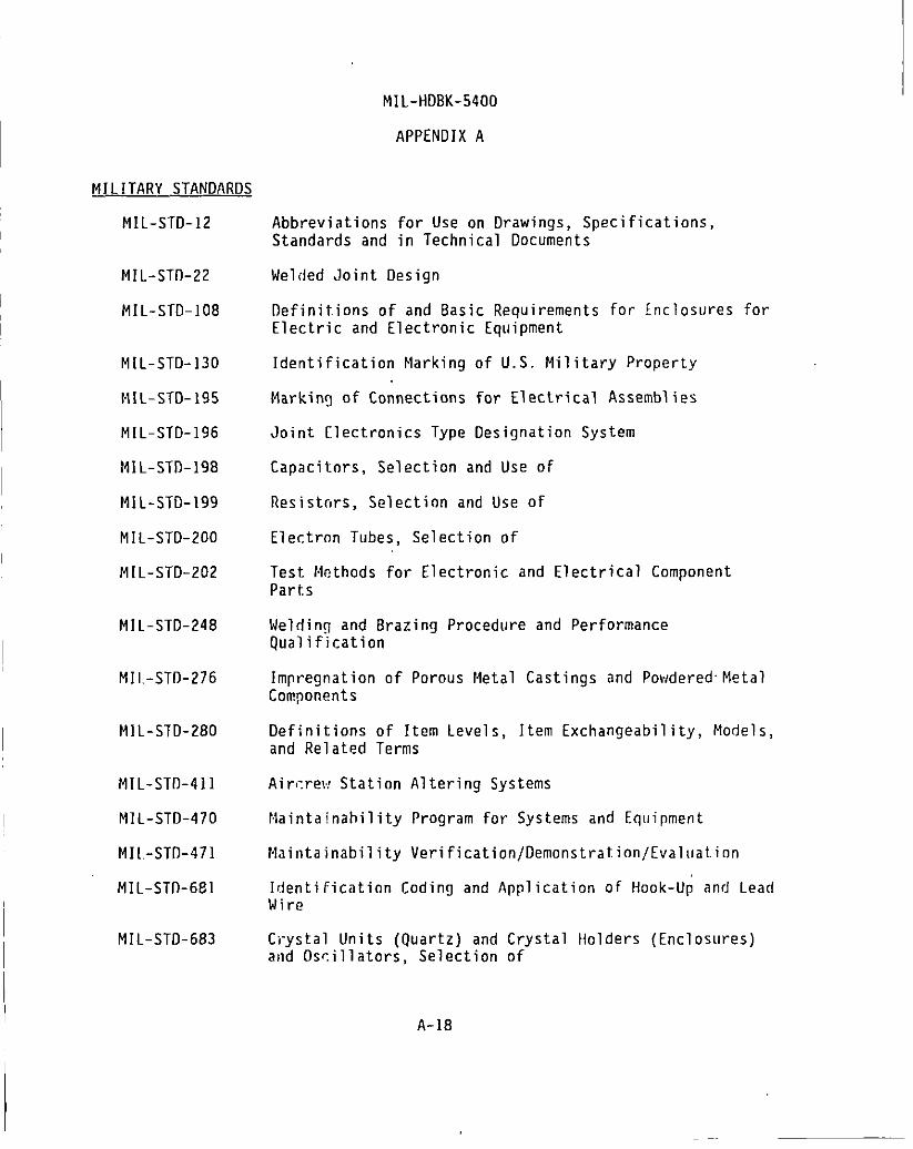
MILITARY STANDARDS
MIL-STD-12
MIL-ST0-22
MIL-STD-108
M I L-STD-130
HIL-STD-195
MIL-STD-196
HIL-STD-198
MIL-STD-199
MIL-STD-200
MIL-STD-202
MIL-STD-248
MIL-STIJ-276
MIL-STD-280
MIL-STIJ-4Jl
MIL-STD-470
MIL.-STIJ- 4 71
MIL-STfl-681
MIL-STD-683
MIL-HDBK-5400
APPENDIX A
Abbreviations for Use on Drawings, Specifications, Standards and in Technical Documents
Welded Joint Design
IJefinitions of and Basic Requirements for Enclosures for Electric and Electronic Equipment
Identification ~larking of U.S. Military Property
Markin~ of Connections for Electrical Assemblies
Joint Electronics Type Designation System
Capacitors, Selection and Use of
Resistors, Selection and Use of
Electron Tubes, Selection of
Test Methods for Electronic and Electrical Component Parts
Weldin!J and Brazing Procedure and Performance Qualification
Impregnation of Porous Metal Castings and Powdered·Metal Components
Definitions of Item Levels, Item Exchangeability, Models, and Related Terms
Air~rew Station Altering Systems
Haintainahility Program for Systems and Eq11ipment
Maintainability VerificationjDemonstrat.ionjEvalJJalion
Identification Coding and Application of Hook-Up and Lead Wire
Ci"ystal Units (Quartz) and Crystal Holders (Enclosures) and Os~illators, Selection of
A-18

MIL-STD-701
Mll-STD-704
Ml L-STD-710
MlL-STD-783
IH L- STD-81 0
MlL-STD-838
MIL-STD-88~
MIL-ST0-889
IHL-STfl-965
MIL-ST0-983
MIL-ST0-1130
HIL- STD-1132
1·\ll-ST0-1189
MIL-STD-1277
MIL-STD-1279
MIL-STD-1285
MIL-STD-1286
MI L-STD-1327
MIL-SHl-1328
MJL-SI0-1329
HI L -HDBK-5400
APPENDIX A
Lists nf Standard Semiconductor Devices
Air~raft Electric Power Characteristics
Synchrns, 60 and 400Hz, Selection and Application of
Legends for Use in Aircrew Stations and on Airhnrne Equipment
Environmental Test Methods and Engineering G.·:·
Luhric~tion of Military Equipment
Test HAthnds and Procedures for Microelectronic~
Dissimilar Metals
Parts rnntrol Program*
Substitution List for Microcircuits
Connections, Electrical, Solderless, Wrapped
Switches and Associated Hardware, Selection and Use of
Standard flepartment of Defense Bar Code Symbology
Splice:., Chips, Terminals, Terminal Boards, Binding Posts, Electrical
Meters, Electrical Indicating, Selection and Use of
Marking of Electrical and Electronic Parts
Transformers, Inductors, and Coils, Selection and Use of
Fhnge~. Coaxial and Waveguide; and Coupling Assemblies, Selection of
Couplel'S, Directional, Selection of
Switches, RF Coaxial, Selection of
* li!L-STD-965 is planned for retention and will be redefined as either a stan,latd practice or an acquisition guideline. A final decision is due by ,January 1996.
A-19

MIL-ST0-1334
HIL-STD-1346
MIL-STD-1352
M!L-STD-1353
~1IL-STD-1358
MJL-STD-1360
MIL-STD-1378
MJL-ST0-1389
MIL-STD-1390
MIL -.ST0-1395
Mll-ST0-1399
Mll-ST0-1472
f1IL-STO-l498
Mll-ST0-1516
11! L-ST0-1553
Mll-STD-1562
MIL-STD-1595
MJL-ST0-1629
MJL-ST0-1636
MIL-ST0-1637
fHL-HDBK-5400
APPENDIX A
Process for Barrier Coating of Anti-Friction Bearings
Relays, Selection and Application of
Attenu;;tors, Fixed and Variable, Selection of
Electrical Connectors, Plug-In Sockets and Associated Hardware, Selection and Use of
Waveguides, Rectangular, Ridge and Circular, Selection of
Fuses, Fuseholders and Associated Hardware, Selection and Use of
RequirP.ments for Employing Standard Electronic Modules
Design Requirements for Standard Electronic .f1odules
Level of Repair Analysis (LORA)
Filters and Networks, Selection and Use of
J nterf.1ce Standard for Shipboard Systems, Section 300 Electric Power, Alternating Current (Metric}
Human Engineering Design Criteria for Military Systems, EquipmP.nt and Facilities
Circuit Rreakers, Selection and Use of
Unified Code for Coatings and Finishes of DOD Equipment
Oigital Time Division Command/Response Multiplex Oata Buss
lists nf Standard Microcircuits
Qualification of Aircraft, Missile and Aerospace Fusion Welders
Procedures .for Performing a Failure Mode, Effects and Criticality Analysis
Adapters, Coaxial to Waveguide, Selection of
Oummy Loads, Electrical, Waveguide, Coaxial, and Stripline, Selection of
A-20

MIL-STD-1638
MIL-STD-1639
MIL-STD-1640
MIL-STD-1646
MIL-STD-1788
MiL.-510-1812
MIL-STD-1861
DOD-STD-1866
MIL-STD-2038
MIL-STD-2113
MIL-STD-2120
MIL-STD-2162
MIL-STD-2175
MIL-STD-2200
MI L-STD-22 I 8
Mll-STD-2219
MS27212
MS33522
MIL-HDBK-5400
APPENDIX A
Waveguide Assemblies, Rigid and Flexible, Selection of
Power Dividers, Power Combiners, and Power Divider; Combiners, Selection of
Mixer Stages, Radio Frequency, Selectic' ··
Servicing Tools for Electric Contacts and ::··c·tions, Selection and Use of
Avionics Interface Design Standard
Type D~signation, Assignment and Method for Obtai~ing
Electrical and Electronic Assemblies, Boards, Cards and Associated Hardware, Selection and Use of
Soldering Process, General (Non-Electrical) (Metric)
Requirements for Employing Standard Power Supplies
Radio Frequency Circulators and Isolators, Selection of
Connectors, Electromagnetic Interference (EM!) Filter Contact
Amplifiers, Radio Frequency and Microwave, Solid State, Selection of
Castin~s, Classification and Inspection of
Req11irements for Employing Standard Enclosure Systems
Thermal Design, Analysis, and Test Procedures for Airllorae Electronic Equipment
Fusion Welding for Aerospace Applications
Terminal Board Assembly, Molded-In Stud, Electric
Rivets, Blind, Structural, Mechanically Locked and Frir.tion Retainer Spindle (Reliability and Maintainability), Design and Construction Requirements for
A-21

MS33540
MS33557
MILITARY HANDBOOKS
M1L=HDRK-5
MIL-IIDflK-216
MlL-HDllK-217
MJL-HDBK-218
1·11 L-HDBK-225
MIL-HDBK-231
MIL-HDBK-246
MlL-HDBK-248
MlL-HDBK-251
Ml L-f!DBK-253
1-11 L-HflBK-263
IHL-HDBK-274
MIL-HOBK-275
111 l-HOBK-402
MIL-HDBK-454
HIL-HDBK-419
IHL-HDBK-5400
APPENDIX A
Safety Wiring and Cotter Pinning, General Practices for
Nonstructural Rivets for Blind Attachment, Limitations for Design and Usage
Metallic Materials and Elements for Aerospac~ ·;~~~cle Structures
RF Transmission Lines and Fittings
Reliability Prediction of Electronic Equipment
Application of Electrical Resolvers
Synchrns, Descriptions and Operation
Encoders, Shaft Angle to Digital
Program Managers Guirle for the Standard Electronic Modules Program
Acquisition Streamlining
Reliability/Design, Thermal Applications
Guidance for the Design and Test of Systems Protected Against the Effects of Electromagnetic Energy
Electrostatic Discharge Control Handbook for Protection of Electrical and Electronics Parts, Assemblies, and Equipment (Excluding Electrically Initiated Explosive Devices) (Metric)
Electrical Grounding for Aircraft Safety
Guirle for the Selection of Lubricant Flttids and Compounds for Use in Flight Vehicles and Components
Gttirtelines for Implementation of DOD Parts Control Program
General Guidelines for Electronic Equipment
Ground, Ronding and Shielding for Electronic Equipments and Far.i1ities
A-22

MIL-HDRK-472
MIL-HDBK-660
MIL-HDBK-691
MIL-HDBK-730
. Ml L-HOBK-1553
MIL-HDBK-2000
1·11L- BU L- I 03
MIL-HDBK-5400
APPENDIX A
Maintainability Prediction
Fabrication of Rigid Waveguide Assemblies (Sweep Bends and Twists) - -
Adhesive Bonding
Materials Joining
Multiplex Application Handbook
Soldering of Electrical and Electronic Assemblies
List of Standardized Military Drawings (SMDS)
OTHEH G!WERNMENT DOCUMEtlTS
NAVAIR-16-1-519, Handbook, Preferred Circuits Navy Aeronautical Vol. 2 Electronic Equipment
10 CFR 20 Code of Federal Regulations, Title 10, Chapter 1, Part 20
21 CFR 1000-1050 Code of Federal Regulations, Title 21, Chapter I, Parts 1000-1050
29 CFR 1910 Code of Federal Regulations, Title 29, Chapter XVII, Part 1910
VHSIC Interoperability Standards. Includes specifications for the TM-bus, ETM bus, Pi bus, ann VHSIC Electrical Specification. (Copies available from Naval Research laboratory, Code 5305, Washington, DC 20375-5000.)
Tester Independent Support Software System (TISSS) Specifications ·(copies available from TISSS Program Office, RADC/RBR, Griffiss Air Force Base, NY 13441-5700).
NON-GOVERNMENT DOCUMENTS
SAE AMS 363BE
SAE AMS 3653D
SAE AMS 3654B
Plastic Tubing, Electrical Insulation, Irradiated Polyolefin, Pigmented, Semi-Rigid, Heat-Shrinkable 2 to I Shrink Ratio
Tubing, Electrical Insulation, Standard Wall, Extruded Polytetrafluoroethylene . (PTFE)
Tubing, Electrical Insulation, Light Wall, Extruded Polytetrafluoroethylene (PTFE)
A-23

SAE AMS 3655A
ASTM A29/A29M
MIL-HDBK-5400
APPENDIX A
Tubing, Electrical Insulation, Thin Wall, Extruded Polytetrafluoroethylene (PTFE)
Steel Bars, Carbon and Alloy, Hot Wrought and Cold Finished, General Requirements for
ASTM A22B/A22BM Steel Wire, Music Spring Quality
ASTM A313 Chromium-Nickel Stainless and Heat Resisting Steel Spring Wire ·
ASTM ASBB/ASSRM Steel, Structural, High-Strength Low Alloy Structural, with 50 KSI (345 MPA), Minimum Yield Point to 4 In. (100 MM) Thick
ASTM A6B2 Steel, Strip, High Carbon, Cold Rolled, Spring Quality, General Requirements for
ASTM A6B4/A6B4M Steel, Strip, High Carbon, Cold Rolled, Standard Specification for
ASTM B134
ASTM B159
ASTM Bl94
Wire, llrass
Wire, Phosphor Wire (Metric)
Copper-Beryllium Alloy Plate, Sheet, Strip, and Rolled Bar
ASTM Bl96/BI96M Copper-Beryllium Alloy Rod and Bar
ASTM B197/Bl97M Copper-Beryllium Alloy Wire
ASTM B206
ASTM 8522
ASTM B633
ASTM 0495
ASTM 0635
ASTM 0!000
Copper-Nickel-Zinc Alloy (Nickel Silver) Wire and Copper Nickel Alloy Wire (Metric)
Gold-Silver-Platinum Electrical Contact Alloy
Electrodeposited Coatings of Zinc on Iron and Steel
Ins11lation, Solid Electrical, High Voltage, Low Current, Dry Arc Resistance of
Plastics, Self-Supporting, in a Horizontal Position, Rate of Burning and/or Extent of Time of, Burning of
Pressure-Sensitive Adhesive Coated Tapes Used for Electrical Insulation, Methods of Testing
A-24

ASTM D3295
ASTM D4956
ASTM F872
ANSif!PC-D322
ANSI C95.1
ANSI C95.2
ANSI N2.1
EiA RS-310-C
IEEE 200
IEEE 1076
NAS498
NAS547
NAS1686
NAS1687
NFPA 70
UL 94
MIL-HDBK-5400
APPENDIX A
PTFE Tubing, Specification for
Sheeting, Retroreflective, For Traffic Control
Filter Unit, Air Conditioning, Viscous Impingement Type, Cleanable
Guidelines for Selecting Printed Wiring Board Sizes Using Standard Panel Sizes
Safety Levels With Respect to Human Exposure to Radio Fr~quency Electromagnetic Fields, 300 KHz to 100 GHz
Radio Frequency Radiation Hazard Warning Symbol
Radiation Symbol
Cabinets, Racks, Panels and Associated Equipment
Electrical and Electronic Parts and Equipments, Reference Designations for
Manual, VHDl Language Reference
Bolts, Shear, 95 KSU FSU
Fastener, Rotary, Quick-Operating, "High Strength
Rivet, Blind, Aluminum Sleeve, Mechanically Locked, Spindle, Bulbed
Rivet, Blind, Monel and Inconel Sleeve, Mechanically locked Spindle, Bulbed
National Electrical Code
Tests for Flammability of Plastic Materials for Parts in Devices and Appliances
Metals Handbook (Vol I) (ASM)
American Gear Manufacturers Association (AGMA)
A-25

MIL-HDBK-5400
APPENDIX B
SAMPLE TAILORING GUIDE
10. SCOPE
10.1 Scope. THIS APPENDIX IS NOT A MANDATORY PART OF THIS HANDBOOK. THE INFORMATION CONTAINED HEREIN IS INTENDED FOR GUIDANCE.
10.2 This appendix provides a sample tailoring guide for MIL-HDBK-5400 based on the relationship of tailoring specific guidelines during various development and production phases as defined in MIL-HDBK-248. This guide is not intended to be restrictive as to the methods/factors to be considered for tailoring applications. Examples of other methods/factors concerned with tailoring of MIL-HDBK-5400 requirements are shown in paragraph 40.
20. APPLICABLE DOCUMENTS (Reference Only) .
MIL-HDBK-248 Acq11isition Streamlining
30. APPLICATION OF SAMPLE TAILORING GUIDE
30.1 The sample tailoring guide contained herein cross-references indications of.tailoring applicability for MIL-HDBK-5400 requirements to various phases of item development and production as defined in MIL-HDBK-248. Codes and abbreviations used in the sample tailoring guide table are as follows:
Tailoring Requirements
N- Not applicable this phase A- Applicable this phase T- Essentially a "tailoring" paragraph G- General statement - tailoring not required
Program Phases
COND&VFSEDPROD-
Conceptual (Research) Demonstration & Validation Fu.ll Scale Engineering Development Production
30.2 Guide for the extent of tailoring to be effected during program phases.
Conceptual (Research) - Specifications and standards requirements should be tailored and limited to minimum technical design objectives and broad basic performance and functional requirements. Application of "cost driver" requirements should be very 1 imited.
B-1

Mll-HOBK-5400
APPENDIX B
Demonstration & validation- Specifications and standards requirements should be tailored again to upgrade and more clearly define the technical objectives relating to design, performance and functional demonstration requirements for the prototype item. Consideration of "cost driver" requirements should be expanded.
Full scale engineering rlevelopment - Specifications and standards requirements should be tailored for maximum compatibility of the ultimate engineering design with the operational system requirements. The application of "cost driver" requirements such as configuration control, quality assurance, reliability, data and documentation, packaging, packing, preservation and transportation lhould be given special
·consideration and definition in anticipation of future procurement. Pertinent general military design requirements should be critically tailored for each applir.ation. A tailored configuration and product baseline should be established prior to entering the production phase.
Production- Proper application of tailored requirements during the engineering design/prototype phase should preclude the necessity for app 1 i cation of addition a 1 military requirements and tailoring during the production phase, except for possible refinement of some requirements.
40. OTHER CONSIDERATIONS FOR TAilORING
40.1 This appendix is limited to guidance for tailoring Mll-HDBK-5400 guidelines to the development and production phases of a program. There are, hru.,,....,,...,.. ......... ., n.+h,...,.. ~,..,..t-,.. ... r ,,,h..;rh ,..,..,.. nW'"nu;l"'a +he h-,.r..;r -Fn..- t-::~;11'\"";"n tn IIUnt:YCIJ IIIQII,Y U\.IIC:I IQ\..IoUI.JI nlll\..11 \..0111-'IVYI'-111;; \.11'1;0 UQ.JII.JI lVI "'QIIVIIII'!f "'V
modify, limit, combine, or eliminate specific requirements consistent w1th the minimum level necessary to provide cost effective system performance and program management. Below is a list of some other ~reas which may provide basis for tailoring of specific requirements relative to those areas of consideration. Refer to MIL-HDBK-248 for additional guidance relative to acquisition streamlining and tailoring of requirements.
Mission requirements Equipment application Environmental/test requirements Interface requirements 11ith other systems/equipment Operational./logistics requirements Software and technical nata requirements Human factors requirements Configuration management requirements Reliability/maintainability requirements Quality assurance requirements Packaging, packing, handling, storage and transportation requirements
B-2

Mll-HDBK-5400
APPENDIX B
PARAGRAPH DESCRIPTION CON D&V FSED PROD
4 .1.1 Tailoring of MIL-HDBK-454 guidelines G G G G 4. !.2 Standard hardware acquisition and
reliability program (SHARP) N N A A 4. !.3 Requirements, tables and figures G G G G 4.2 Design and construction G G G G
. 4. 2 .I Untitled G G G G TABLE I General design and construction 4.2.2 Accessibility N N A A 4.2.3 Anti-jamming N A A A 4.2.4 Castings, metal N N N A 4.2.5 Corona and electrical breakdown prevention A A A A 4.2.6 Derating N A A A 4.2.7 Electrical overload protection N N A A 4.2.7.1 Resettable circuit protectors N N A A 4.2.7.2 Spare fuses N N A A 4.2.8 Electrical power N N A A 4.2 .8.1 Warm-up time N N A A 4.2.8.2 Untitled N N A A 4.2 .9 Electromagnetic interference control N N A A 4. 2.10 Electrostatic discharge control A A A A 4. 2.11 Enciosures N N A A 4.2.11.1 Standardized avionics enclosures N N A A 4.2.11.2 Other enclosures N N A A 4.2.12 Fabrication N N A A 4. 2.13 Grounding, bonding and shielding A A A A 4.2.14 Human engineering N N A A 4.7..15 Interchangeability N N N A 4.2.15.1 Interchangeability of reordered equipment N N N A 4.2.16 Maintainahil ity N N A A 4. 2.17 Marking N· N A A 4.2.17.1 Lahels N N N A 4.2.17.2 Wire coding·for identification N N N A 4.2.17.3 Operational program marking N N N A 4. 2.18 Microphonics G G G G
4. 2.19 Moisture pockets N N N A 4.2 .20. Multiplexing N N A A 4.2 .2[ Nomenclature assignment N N N A 4.2.22 Orientation N N A A 4.2.23 Panels N A A A 4. 2. 23. I Control panels N A A A 4.2.23.2 Electroluminescent panels N A A A 4.2.23.3 Ranges of ad.i11stahle parts N A A A
B-3

MIL-HDBK-5400
APPENDIX B
PARAGRAPH DESCRIPTION CON D&V FSED PROD \
4.2.24 Pressurization N N A A 4.2.25 Re 1 i abil ity N N A A 4.2.26 Repairability N N A A 4.2.27 Safety G G G G 4.2.27.1 System safety G G G G 4.2.27.2 Personnel Safety A A A A 4.2.28 Test provision N N A A 4.2.28.1 Built-in test devices N N A A 4.2.28.2 External test points N N A A 4.2.28.3 Failure effect N N A A 4.2.29 Testability program N N A A 4.2.30 Thermal design N N A A 4.2.30.1 Cooling design data N N A A 4.2.31 Tools N N N A 4.2.31.1 Setscrew wrenches N N N A 4.2.31.2 Special tool N N N A 4.2.31.3 Furnishing and stowing N N A A 4.2.32 Standardized power s11pplies N N A A 4.2.33 Workmanship N N A A 4.3 Parts selection N A A A 4.3.1 Government.-furni shed baseline (GFB) N A A A 4.3.1.1 Choice of parts N A A A 4.3.2 Nonstandard parts N A A A 4.3.3 Parts control program N A A A 4.3.4 Approval nf parts N A A A 4.3.4.1 Contracts under category I T T T T 4.3.4.2 Contracts for equipment which fall under
categories II and III T T T T .4.3.4.3 Reordered production equipment T T T T 4.3.4.3.1 Continuation of production T T T T 4.3.4.4 Replacing of approved parts · N A A A 4.3.4.5 Equipment performance G G G G TABLE II Parts selection 4.3.5 Substitution of parts N A A A 4.3.6 Batteries N A A A 4.3.7 Bearings N N A A 4.3.8 Capacitors N A A A 4 .3.8.1 Fixed, tantalum electrolytic N A A A 4.3.8.2 Aluminum electrolytic N A A A 4.3.9 Circuit breakers N A A A 4.3.9.1 Manual operation N A A A 4.3.9.2 Position identification N A A A 4.3.9.3 Orientation N N A A
B-4
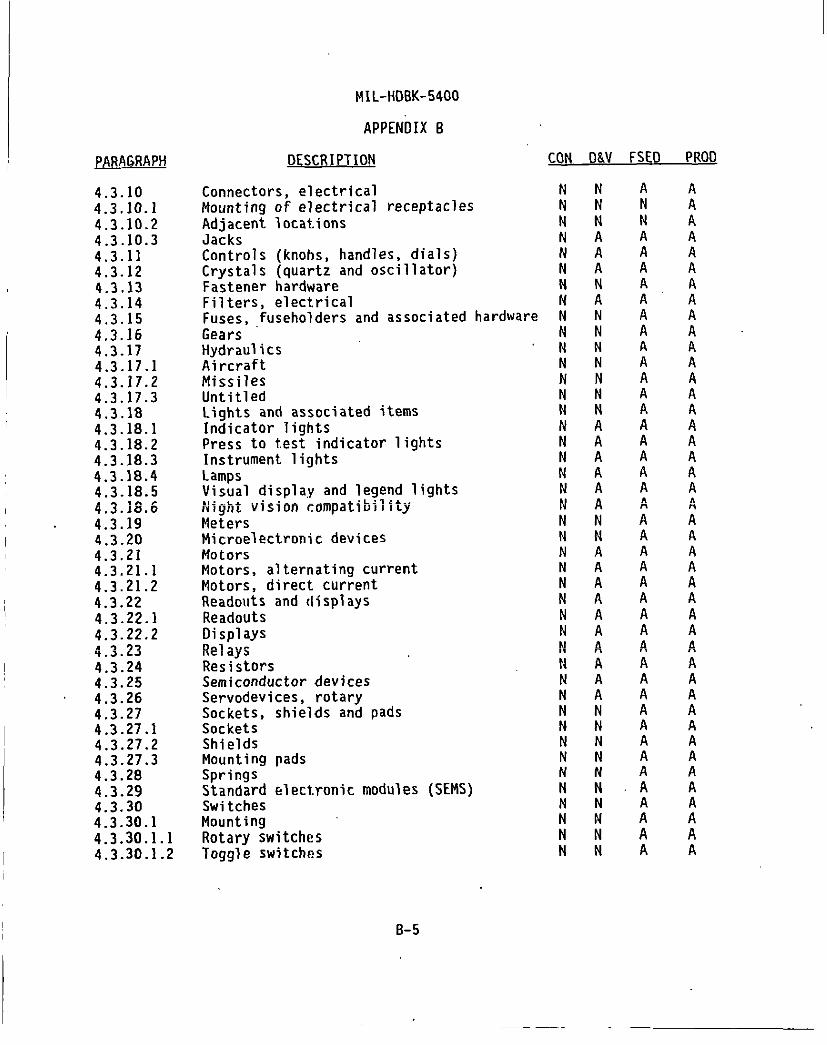
MIL-HOBK-5400
APPENDIX B
PARAGRAPH DESCRIPTION CON D&.V FSED PROD
4.3.10 Connectors, electrical N N A A 4.3.10.1 Mounting of electrical receptacles N N N A 4.3.10.2 Adjacent locations N N N A 4.3.10.3 Jacks N A A A 4.3.11 Controls (knobs, handles, dials) N A A A 4.3.12 Crystals (quartz and oscillator) N A A A 4.3.13 Fastener hardware N N A A 4. 3.14 Filters, electrical N A A A 4. 3.15 Fuses, fuseholders and associated hardware N N A A 4.3.16 Gears N N A A 4.3.17 Hydraulics N N A A 4.3.17 .I Aircraft N N A A 4.3.17.2 Missiles N N A A 4.3.17.3 Untitled N N A A 4.3 .18 Lights and associated items N N A A 4.3.18.1 Indicator lights N A A A 4.3.18.2 Press to test indicator lights N A A A 4.3.18.3 Instrument lights N A A A 4.3.18.4 lamps N A A A 4.3.18.5 Visual display and legend lights N A A A "' ... , "" ,. Night vision r.ompatibility " A A A q • .,.Hl.O " " " " 4.3.19 Meters N N A A 4.3.20 Microelectronic devices N N A A 4.3.21 Motors N A A A 4.3.21.1 Motors, alternating current N A A A 4.3.21.2 Motors, direct current N A A A 4.3.22 Readouts and displays N A A A 4.3.22.1 Readouts N A A A 4.3.22.2 Displays N A A A .4 ., .,., Re1 ays p,J d A d 't • .J·'~ " n n
4.3.24 Resistors N A A A 4.3.25 Semiconductor devices N A A A 4.3.26 Servodevices, rotary N A A A 4.3.27 Sockets, shields and pads N N A A 4.3.27 .1 Sockets N N A A 4.3.27.2 Shields N N A A 4.3.27.3 Mounting pads N N A A 4.3.28 Springs N N A A 4.3.29 Standard electronic modules (SEMS) N N A A 4.3.30 Switches N N A A 4.3.30.1 Mounting N N A A 4. 3. 30 .1.1 Rotary switches N N A A 4.3.30.1 .2 Toggle switches N N A A
B-5

PARAGRAPH
4.3.31 4.3.31.1 4.3.31.2 4.3.31.3 4.3.32 4.3.33 4.3.34 ~.3.35 4.3.35.1 4.3.35.2 4.3.35.3 4.3.35.4 4.3.35.5 4.3.35.6 4.4 4.4 .I 4.4.2 4.4.3 4.4.4 4.4.4.1 TABLE III 4.4.5 4.4.6 4.4.7 4.4.8 4.4.9 4.4 .10 4.4. !1 4. 4.12 4. 4.13
4.4.14 4.4.15 4.5 TABLE IV 4.5.1 4.5.1.1 4.5.1.2 4.5.1.2.1 4.5.1.2.2 4.5.1.2.3 4.5.2 4.5.3 4.5.4 4. 5.4 .1
MIL-HDBK-5400
APPENDIX B
QESCR I PHON
Terminations Number of wires per terminal or lug Number of lugs per terminal Number of wires in a connector contact Transformers, inductors and coils Tubes, electron Waveguides and related items Wire and cable Wire and cable, internal Wiring practices, internal Wire and cable, external interconnection External wiring practices Cable, coaxial (RF) Printed wiring Material selection Choice of materials Polyvinyl chloride (PVC) materials Standard materials Nonstandard materials Approval of nonstandard materials Materials selection Adhesives Arc-resistant materials Conformal coating Dissimilar metals Encapsulation and embedment materials Fibrous material, organic Flammability of materials Fungus-inert materials Ins~lators, insulating and dielectric
materials Lubricants Metals, corrosion-resistant Processes and finishes Processes and finishes Protective platings and coating Materials Aluminum alloy Surface, general Surfaces, bonded and grounded Surfaces, extreme wear-resistant Magnesium and magnesium alloys Zinc and zinc-plated parts Finishes Cases and front panels
B-6
CON D&V FS£0 PROD
N N N N N N G G N A N A N N N N N N N N N N G G N N N N N N N A N A N A N A N A
N N A A N N N N N N N N N N N A
N A N N N N G G
G G G G G G G G G G G G G G G G N N N . N
A A A G A A A A A A A G A A A A A A A A
A A A A N A A A
A A A G
G G G G G G G G A A
A A A G A A A A A A A G A A A A A A A A
A A A A A A A A
A A A G
G G G G G G G G A A

MIL-HDBK-5400
APPENDIX B
PARAGRAPH DESCRIPTION CON D&V FSED PROD
4.5.4.2 Fasteners and assembly screws N N A A 4.5.4.3 Other standarrl finishes G G G G 4.6 Environmental service guidelines N N A A 4. 6.1 MIL-STD-810 environmental tests T T T T 4.6.1.1 Untitled T T T T 4.6.2 Equipment operational requirements N N A A 4.6.2.1 Temperature N N A A 4.6.2.1.1 Operating N N A A TABLE V Environmental conditions 4.6.2.1.2 Nonoperating N N A A 4.6.2.2 Altitude N N A A 4.6.2.3 Temperature-altitude combination N N A A 4.6.2.4 Humidity N N A A 4.6.2.5 Vibration N N A A 4.6.2.5.1 Equipment normally mounted N N A A 4.6.2.5.1.1 Equipment designed for installation in
propeller aircraft N N A A 4.6.2.5.1.2 Equipment designed for installation in
jet aircraft N N A A 4.6.2.5.1.3 Equipment designed for installation in
helicopters N N A A 4.6.2.5.1.4 Minimum integrity test N N A A 4.6.2.6 Shock N N A A 4.6.2.6.1 Equipment N N A A 4.6.2.6 2 Mounting hase (crash safety) N N A A 4.6.2.6 3 Bench handling N N A A 4.6.2.7 Sanrl and dust N N A A 4.6.2.8 Fungus N N A A 4.6.2.9 Sa 1t. atmosphere N N A A 4.6.2.10 Explosive conrlitions N N A A
B-7

MIL-HDBK-5400
INDEX
Description Paragraph Page
ft-----~L~1~+•• • #\1..\..t::':>:) I U I I I \.:f ••••.• , •,, ••••• • • •.,,., ............ , ••• A ? ? 5 ,.,L.oL.
Accessory ......................................... . Acquisition activity ........................ · ...... :
3. I 2 3.2 2
Adhesives ......................................... . 4.4.5 24 Adjacent locations ................................ . 4.3.10.2 18 Airborne ....................................... : .. . 3.3 2 Aircraft .......................................... . 4.3.17.1 19 Altitude .......................................... . 4.6.2.2 35 Aluminum alloy .................................... . 4.5.1.2 26 Aluminum electrolytic ............................. . 4.3.8.2 17 Anti -jamming ...................................... . 4.2.3 5 APPLICABLE DOCUMENTS .............................. . 2. 2 Applicable issues ................................. . 2.2 2 Application ....................................... . l. 1.1 I Approval of nonstandard materials ................. . 4 .4.4.1 24 Approval of parts ............................... . 4.3.4 16 Arc-resistant materials ........................... . 4.4.6 25
Batteries ... · ...................................... . 4.3.6 17 Bearings .......................................... . 4.3.7 17 Bench handling .................................... . 4.6.2.6.3 36 Built-in test devices ............................. . 4. 2. 28.1 12
Cable, coaxial (RF) ............................... . 4.3.35.5 23 Capacitors ........................................ . 4.3.8 17 Cases and front pane 1 s ............................ . 4. 5. 4.1 28 Castings, metal ................................... . 4.2.4 6 Choice of materials ............................... . 4. 4.1 23 Choice of parts ................................... . 4.3.1.1 14 Circuit breakers .................................. . 4.3.9 17 Classification .................................... . 1.2 I Complete operating equipment ...................... . 3.4 2 Conformal coating ............................. _. ... . 4.4.7 25 Connectors, electrical ............................ . 4.3.10 18 Continuation of production ........................ . 4.3.4.3.1 16 Contracts for equipment which fall under Categories
11 and I I I .................................. · .... . 4.3.4.2 16 Contracts under Category I ........................ . 4.3.4.1 16 Control panels .................................... . 4.2.23.1 10 Controls (knobs, handles, dials) .................. . 4. 3 .II 18 Cooling design data ............................. . 4.2.30.1 13 Copies ............................................ . 2.3 2 Corona and electrical breakdown prevention ........ . 4.2.5 6 Crystals (quartz and oscillator) .................. . 4.3.12 18

MIL-HDBK-5400
INDEX
Description
Accessibility ..................................... . Accessory ......................................... . Acquisition actlvity .............................. . Adhesives ......................................... . Adjacent locations ................................ . Airborne .......................................... . Aircraft. ......................................... .
·Altitude .......................................... . Aluminum alloy .................................... . A1u'!'i~um :1ectro1ytic. ............................ . Ant1-Jamm1ng ...................................... . APPLICABLE DOCUMENTS .............................. . Applicable issues ................................. . Application ....................................... . Approval of nonstandard materials ................. . Approval of parts ............................... . Arc-resistant materia 1 s ........................... .
Batteries .......................... : .............. . Bearings .......................................... . Bench handling .................................... . Built-in test devices ............................. .
Cable, coaxial (RF) ............................... . Capacitors ........................................ . Cases and front pane 1 s ............................ . Castings, metal ................................... . Choice of materials ............................... . Choice of parts ................................... . Circuit breakers .................................. . Classification .................................... . Complete operating equipment ...................... . Conformal coating ................................. . Connectors, electrical ...................... · ...... . Continuation of production ......................•.. Contracts for equipment which fall under Categories
II and I I I ...................................... . Contracts under Category I ........................ . Control panels .................................... . Controls (knobs, handles, dials) .................. . Cooling design data ............................. . Copies ............................................ . Corona and electrical breakdown prevention ......... . Crystals (quartz and oscillator) .................. .
1=2
Paragraph Page
4.2.2 5 3 .I 2
. 3.2 2 4.4.5 24 4.3.10.2 18 3.3 2 4.3.17.1 lg 4.6.2.2 35 4. 5 .I. 2 26 4.3.8.2 17 4.2.3 5 2. 2 2.2 2 1.1.1 I 4.4.4.1 24 4.3.4 16 4.4.6 25
4.3.6 17 4.3.7 17 4.6.2.6.3 36 4. 2. 28.1 12
4.3.35.5 23 4.3.8 17 4.5.4.1 28 4.2.4 6 4.4.1 23 4.3.1.1 14 4.3.9 17 1.2 I 3.4 2 4.4.7 25 4. 3.10 .18 4.3.4.3.1 16
4.3.4.2 16 4.3.4.1 16 4.2.23.1 10 4.3.11 18 4.2.30.1 13 2.3 2 4.2.5 6 4.3.12 18

MIL-HDBK-5400
INDEX (continued)
Description Paragraph Page
DEFINITIONS ...................................... . 3. 2 Derating ......................... ··· ... ··········· 4.2.6 7 Design and construction .......................... . 4.2 5 Design qualification tests ....................... . 5.3.5 38 Detailed mechanical and electrical design ........ . 5.1 37 Detail specification ............................. . 3.5 3 DETAIL GUIDELINES ................................ . 5. 37 Details for inclusion in equipment specifications
and contracts ............................... . 6.2 3g Displays ......................... : .............. . 4.3.22.2 20 Dissimilar metals ................................ . 4.4.8 25 Documents ................................... ~ .... . 2.1 2
Electrical overload protection ................... . 4.2.7 7 El ectri ca 1 power ................................. . 4.2.8 7 Electroluminescent panels ........................ . 4.2.23.2 10 Electromagnetic interference contro 1 ............. . 4.2.9 7 Electrostatic discharge control .................. . 4 .2.10 7 Electronics ............................ .- ..... · .... . 3.6 3 Encapsulation and embedment materials ............ . 4.4.9 25 Enc 1 osures ....................................... . 4. 2.11 8 Environmental service requirements ............... . 4.6 28 Environment conditions ........................... . TABLE V 30 Equipment. ....................................... . 3.7 3 Equipment ........................................ . 4.6.2.6.1 36 Equipment designed for installation in · helicopters ................................ . 4.6.2.5.1.3 35 Equipment designed for installation in
jet aircraft. .............................. . Equipment designed for installation in propeller
4.6.2.5.1.2 35
aircraft. .................................. . 4.6.2.5.1.1 35 Equipment normally mounted ....................... . 4.6.2.5.1 35 Eq11ipment operational requirements ............... . 4.6.2 29 Equipment performance ............................ . 4.3.4.5 17 Explosive conditions ............................. . 4.6.2.10 37 Extern a 1 coo 1 i ng ................................. . 1. 2. I 2 External test points ............................. . 4.2.28.2 12 External wiring practices ....................... . 4.3.35.4 23
Fabrication ..................................... . 4.2.12 8 Failure criteria ................................. . 5.3.3 37 Failure effect ................................... . 4.2.28.3 12 Fastener hardware ................................ . 4.3.13 18 Fasteners and assembly screws .................. ··~ 4.5.4.2 28
1-3

MIL-HDBK-5400
INDEX (continued)
Description Paragraph Page
Fibrous material, organic ........................ . 4.4.10 25 Filters, electrical .............................. . 4.3 .14 19 Finishes ......................................... . 4.5.4 28 First article tests .............................. . 5.3.6 38 Fixed tantalum, electronic ....................... . 4 .3.8.1 l7 Flammability of materials ........................ . 4 .4.11 25 Fungus .................................... · · · .... · 4.6.2.8 36 Fungus-inert materials ........................... . 4 .4.12 25 Furnishing and stowing ............. , ............. . 4.2.31.3 13 Fuses, fuseholders and associated hardware ....... . 4 .3.15 19
Gears ............................... · · · · · · · · · · · · · · 4.3.16 19 General design and construction ............... . TABLE I 6 GENERAL GUIDELINES ............................... . 4. 4 Government-furnished baseline (GFB) .............. . 4.3.! !4 Government verification .......................... . 5.3.2 37 Grounding, bonding and shielding ................. . 4. 2.13 8
Hermetic sealing ......................... ; ........ . Human engineering ................................ .
3.8 3 4.2.14 8
Humidity .................................. ········ Hydraulics ................. .' ..................... .
4.6.2.4 35 4.3.17 19
Ind·icator lights ................................. . 4.3.18.1 19 Installation (complete equipment) ................ . 3.9 3 Instrument lights ................................ . 4.3.18.3 19 Insulators, insulating and dielectric materials .. . 4.4.13 25 Intended use .............. : ...................... . 6 .I 39 Interchangeability ............................... . 4.2.15 8 Interchangeability of reordered equipment ........ . 4.2.15.1 8 Intermittent and short-time operation ............ . 3.10 3
Jacks .............................. · · · · · · · · · · · · · · · 4.3.10.3 18
Labels ........................................... . 4.2.17.1 9 Lamps ............................................ . 4.3.18.4 19 Lights and associated items ...................... . 4.3.18 19 Luhri cants ....................................... . 4.4.14 25
Magnesium and magnesium alloys ................... . 4.5.2 26 Maintainability ............................ · ...... . 4.2.16 9 Manu a 1 operation ................................. . 4.3.9.1 17 Marking .......................................... . 4. 2. j i 9
I-4

MIL-HDBK-5400
INDEX (continued)
Description
M::r.t.o..-i::r.lc IIU ..... I IU.IJoooo o ooo • oo o •• o o o o o •• o o o o o o oo o o oo, oo o oo o o
Materia 1 se 1 ec:t ion ............................... . Materials selection .............................. . Metals, corrosion resistant. ..................... . Meters ........................................... . Microelectronics devices ......................... . Mi crophoni cs ................................ : .... . MIL-STD-810 environmental tests .................. . Minimum integrity test. .......................... . Missiles ......................................... . Moisture pockets ................................. . Motors ........................................... . Motors, alternating current ...................... . Motors, direct current. .......................... . Mounting ......................................... . Mounting base (crash safety) ..................... . Mounting of electrical receptacles ............... . Mounting pads .................................... . Multiplexing ....................... · .............. .
Night vision compatibility ......................... . Nomenclature assignment .......................... . Nonoperating ..................................... . Nonstandard materia 1 s ............................ . Nonstandard parts ................................ . NOTES ............................................ . Number of 1 ugs per term ina 1 ...................... . Number of wires per terminal or lug .............. . Number of wires in a connector contact .......... .
Operating ........................................ . Operation a 1 program marking ...................... . Operational requirements fnr c:lass I
airborne electronic equipment (temperature vs altitude) ................. .
Operational requirements for class 2 airborne electronic equipment (temperature vs a 1 t i tude) .................. .
Operational requirements for class 3 airborne electronic equipment (temperature vs altitude) .................. .
Operational requirements for class 4 airborne electronic equipment (temperature vs altitude) ................... ·
Paragraph Page
d ~ 1 1 26 --y ............
4.4 23 TABLE III 24 4.4.15 25 4.3.19 20 4.3.20 20 4.2.18 9 4.6 .1 28 4.6.2.5.1.4 35 4.3.17.2 19 4.2.19 9 4.3.21 20 4.3.21.1 20 4.3.21.2 20 4.3.30.1 21 4.6.2.6.2 36 4.3.10.1 18 4.3.27.3 21 4.2.20 9
4.3.18.6 20 4.2.21 10 4.6.2.1.2 29 4.4.4 24 4.3.2 14 6. 39 4.3.31.2 22 4.3.31.1 22 4.3.31.3 22
4.6.2.1.1 29 4.2.17.3 9
FIGURE l 31
FIGURE 2 32
FIGURE 3 33
FIGURE 4 34

MIL-HDBK-5400
INDEX (continued)
Description
Orientation ...................................... . Orientation ...................................... . Other component definitions ..................... . Other enclosures ................................ . Other standard finishes .......................... .
Panels ........................................... . Parts control program ............................ . Parts selection .................................. . Parts selection .................................. . Performance requirements of the equipment .... : ... . Permanently installed part ....................... . Personne 1 safety ................................. . Polyvinyl chloride (PVC) materials ............... . ... __ ,...__,.- _._J __ ..._.,., __ ...__._
~OSlLlOn lOenLlTlCaLlOn .......................... . Preparation for de 1 i ver.v ......................... . Press to test indicator lights ................... . Pressurization ................................... . Printed wiring ................................... . Problem/failure reporting and corrective action .. . Processes and finishes .... : ... · ................... . Processes and finishes ........................... . Protective platings and coating .................. . O .. hl;r .... ;nnr-'UUI 1\.Q!o.IUII_,,,,,,,, •. ,,,,,,,,,,,,,,,,,,,,,, 0 ,,,,,,
Quality assurance ................................ . Qua 1 i ty conformance tests ........................ .
Ranges of•djustable parts ...................... . Readouts ancl displays ............................ . Readouts ........................................ . Relays ........................................... . Reliability ................................. ~ .... . Removable assemhly ............................... . Reordered production eq11ipment ................... . Reordered production equipment. .................. . Repa i rabi 1 ity .................................... . Replacing of approved parts ...................... . Requirements, tables and figures ................. . Resettable circuit protectors .................... . Res i stars .................................. - ..... . Resoonsibilitv for tests and insoections ......... . Rotary switches ................. · ................. .
1-6
Paragraph
4.2.22 4.3.9.3 3.11 4.2.11.2 4.5.4.3
4.2.23 4.3.3 4.3 TABLE II 3.12 3.13 4.2.27.2 4.4.2. • .,. n ,. '1 • .).:1.£
5.4 4.3.18.2 4.2..24 4.3.35.6 5.3 .4 . 4.5 TABLE IV 4.5.1 " d v.~
5.3 5.3.7
4.2.23.3 4.3.22 4.3.22.1 4.3.2.3 4.2.25 3.14 3.15 4.3.4.3 o\.2.26 4.3.4.4 4.1.3 o\.2.7.1 o\.3.24 5.3.1 4.3.30.1.1
Page
10 1B 3 B
28
10 14 14 15
4 4
12 24 18 39 19 10 23 38 26 27 26 41
37 38
10 20 20 20 l! 4 4
16 12 17 5 7
20 37 21

MIL-HDBK-5400
INDEX (continued)
Description Paragraph Page
Safety ........................................... . 4.2.27 12 Salt atmosphere .................................. . 4.6.2.9 36 Sand and dust .................................... . 4.6.2.7 36 SCOPE ............................................ . I. I Scope ........... : . ............................... . 1.1 I Scope of tests ................................... . 5.3.6.1 38 Semiconductor devices ............................ . 4.3.25 21 Servodevi ces, rotary ............................. . 4.3.26 21 Setscrew wrenches ................................ . 4.2.31.1 13 Shields ........................ ." ................. . 4.3.27.2 21 Shock ............................................ . 4.6.2.6 36 Sockets .......................................... . 4.3.27.1 21 Sockets, shields and mounting pads ............... . 4.3.27 21 Spare fuses ...................................... . 4.2.7.2 7 Spec:i al tools .................................... . 4.2.31.2 13 Springs .......................................... . 4.3.28 21 Standard electronic modules (SEMS) ............... . 4.3.29 21 Standard hardware acquisition and reliability
program (SHARP) ................ ; ........... . 4.1.2 4 Standardized avionics enclosures ................. . 4.2.11.1 8 Standardized power supplies ...................... . 4.2.32 13 Standard materia 1 s ............................... . 4.4.3 24 Subject term (keyword) listing ................... . 6.5 41 Substitution of parts ............................ . 4.3.5 17 Surface, genera 1 ................................. . 4.5.1.2.1 26 Surfaces, bonded and grounded ..................... . 4.5.1.2.2 26 Surfaces, extreme wear-resistant ................. . 4.5.1.2.3 26 Switches ......................................... . 4.3.30 21 System safety ..................................... . 4.2.27.1 12
Tailoring ........................................ . 1.1.2 I 'Tailoring of MIL-H08K-414 ~uidelines ............. . 4 .I. I 4
Technical data ................................... . 5.2 37 Temperature ...................................... . 4.6.2.1 29 Temperature-altitude combination ................. . 4.6.2.3 35 Terminations ..................................... . 4.3.31 22 Testability program .............................. . 4.2.29 12 Test provisions .................................. . 4.2.28 12 Thermal design ................................... . 4.2.30 13 T ngg 1 e switches .................................. . 4.3.30.1.2 21 Too 1 s ............................................ . 4.2.31 13 Trans formers, inductors anti coi 1 s ................ . 4.3.32 22 Tubes, electron .................................. . 4.3.33 22
1-7

MIL-HDBK-5400
INDEX (continued}
Description Paragraph Page
Untitled ......................................... . 4 .1 4 Unt it 1 ed ......................................... . 4. 2.1 5 Untitled ......................................... . 4.2.8.2 7 Unt it 1 ed ......................................... . 4.3.17.3 19 Untitled ......................................... . 4.6.1.1 29 Use of helium .................................... . 6.3 40 Vibration ........................................ . 4.6.2.5 35
. Visual display and legend lights ................. . 4.3.18.5 20
Warm-up time.......... . ........................ . 4. 2 .8.1 7 Waveguides and related items ..................... . 4.3.34 22 Wire and cable ................................... . 4.3.35 22 Wire and cable, external interconnection ......... . 4.3.35.3 23 Wire and cable, internal. ........................ . 4.3.35.1 22 Wire coding for identification ................... . 4.2.17.2 9 Wiring practices, internal ....................... . 4.3.35.2 23 Workmanship ...................................... . 4.2.33 13
Zinc and zinc-plated parts .. ·······'·············· 4.5.3 28
1-8

/
STANDARDIZATION DOCUMENT IMPROVEMENT PROPOSAL
INSTRUCTIONS
1. The preparing acdvity must complete bloch 1, 2, 3. end 8. In block 1. both the document number and revision letter should be given.
2. The submitter of this form must complete blocks 4, 5, 6, and 7.
3. Th• preparing activity must provid~ 1!1 reply within 30 days from receipt of the form. NOTE: This hum may not be u .. d to request copies of dDCUmenu. nor to request waivers. or clarification of requirements on current contracts. Comments submitted on this form do not C005titute or Imply authorization to wolve any portion of the referenced doeumentls1 or to amend contractual requiremenu.
1. DOCUMENT MJMB£R 2. DOCUMENT DATE
·I RECOMMEND A CHANGE: II'"VMMDOl
MIL-HDBK-5400 951130
3. DOCUMENT TITLE
ELECTRONIC EQUIPMENT. AIRBORNE GENERAL GUIDELINES FOR
-4. NATUI'I; Of CHANGt loli:IMrlfy ,_.., ~ Prd i'JCJI'IIao ~ ,.wrift, II poulb4. Att.ch •nr• ~ u t~Mehd.\
6. REASON FOR RECOMMENDATION
•. SU8MITT£R
•· NAME l.lar. Fht. Alb:~~. "l/tJMI b. ORGANIZATION
c. ADDRESS lftc;tldlt Zip Codrl d. TELEPHONE 7. DATE SUBMmED
llnclud• Aru CDdo) IVYMMDDI
(1) Commerdbl:
12) OSN: .. __ , . 8. PREPARING ACTIVITY
~. N.U1E b. TEL!PHONE NUMBER I~ AIN Codt) COMMANDER I 1) eomn-ctal 121 DSN NAVAL AIR WARfARE CENTER 1908)323·2970 624·2970 AU\CS\An DNtSION
c. AODAESS ~Zip Codll F YOU DO NOT AEa!VE A RB'I.Y wmall45 DAYS, CQIITACT: cooe 4.1.11.28120.3 o.t.,.. Cl&alty ..:1 StandanBEatlan ~. 5203Leatlurg Plk•. HIGHWA."l 547 Suh• 1403, Fllb Church. VA 22041·3466 LAKEHURST, tu 08733·6100 T~ 17031766-2340 DSN 289·2340
0 Form 1426, OCT 89 P,.llioln edition$ .,. Ob$~t. 198/290