Embed Size (px)
Citation preview

DEPARTMENT OF DEFENSE
MILITARILY CRITICAL TECHNOLOGIESLIST
SECTION 19: SPACE SYSTEMS TECHNOLOGY
October 2005
Under Secretary of Defense, Acquisition, Technology and LogisticsPentagon, VA

MCTL-19-i
PREFACE
A . THE MILITARILY CRITICAL TECHNOLOGIES PROGRAM (MCTP)
The MCTP supports the development and promulgation of the congressionally mandated Militarily CriticalTechnologies List (MCTL) and the Developing Science and Technologies List (DSTL).
Congress assigns the Secretary of Defense the responsibility of providing a list of militarily critical technolo-gies (the MCTL) and of updating this list on an ongoing basis. The MCTL identifies technologies crucial to weap-ons development and has been a key element in evaluating U.S. and worldwide technological capabilities. TheMCTP has provided the support for a wide range of assessments and judgments, along with technical justificationsfor devising U.S. and multilateral controls on exports. The DSTL, another MCTP product, identifies technologiesthat may enhance future military capabilities and provides an assessment of worldwide science and technology (S&T)capabilities.
The MCTP process is a continuous analytical and information-gathering process that refines information andupdates existing documents to provide thorough and complete technical information. It covers the worldwide tech-nology spectrum and provides a systematic, ongoing assessment and analysis of technologies and assigns values andparameters to these technologies.
TWGs, which are part of this process, provide a reservoir of technical experts who can assist in time-sensitiveand quick-response tasks. TWG chairpersons continuously screen technologies and nominate items to be added orremoved from the list of militarily critical technologies. In general, TWG members are drawn from about 1,000 sub-ject matter experts (SMEs) from the military Services, DoD and other federal agencies, industry, and academia. Abalance is maintained between public officials and private-sector representatives. TWGs collect a core of intellectualknowledge and reference information on an array of technologies, and these data are used as a resource for projects andother assignments. Working within an informal structure, TWG members strive to produce precise and objectiveanalyses across dissimilar and often disparate areas. Currently, the TWGs are organized to address 20 technologyareas:
Aeronautics Information Systems
Armament and Energetic Materials Lasers, Optics, and Imaging
Biological Processing and Manufacturing
Biomedical Marine Systems
Chemical Materials and Processes
Directed and Kinetic Energy Systems Nuclear Systems
Electronics Positioning, Navigation, and Time
Energy Systems Signature Control
Ground Combat Systems Space Systems
Information Security Weapons Systems
B . THE MILITARILY CRITICAL TECHNOLOGIES LIST (MCTL)
The expanded MCTL provides a coordinated description of existing goods and technologies that DoD assesseswould permit significant advances in the development, production, and use of military capabilities by potentialadversaries. It includes goods and technologies that enable the development, production, and employment of weapons
MCTL-19-ii
of mass destruction (WMD) and their means of delivery. It includes discreet parameters for systems; equipment;subassemblies; components; and critical materials; unique test, inspection, and production equipment; unique soft-ware, development, production, and use know-how; and worldwide technology capability assessments.
C . LEGAL BASIS FOR THE LIST OF MILITARILY CRITICAL TECHNOLOGIES
The Export Administration Act (EAA) of 1979 assigned responsibilities for export controls to protect tech-nologies and weapons systems. It established the requirement for DoD to compile a list of militarily critical tech-nologies. The EAA and its provisions, as amended, were extended by Executive Orders and Presidential directives.
D . USES AND APPLICATIONS
The MCTL is not an export control list. Items in the MCTL may not appear on an export control list, anditems on an export control list may not appear in the MCTL. The document is to be used as a reference forevaluating potential technology transfers and for reviewing technical reports and scientific papers for public release.Technical judgment must be used when applying the information. It should be used to determine if the proposedtransaction would result in a transfer that would give potential adversaries access to technologies whose specificperformance levels are at or above the characteristics identified as militarily critical. It should be used with otherinformation to determine whether a transfer should be approved.
This document, MCTL Section 19, Space Systems Technology supersedes MCTL Part I, Section 17, SpaceSystems Technology.
MCTL-19-iii
INTRODUCTION
A . ORGANIZATION OF THE MILITARILY CRITICAL TECHNOLOGIES LIST (MCTL)
The MCTL is a documented snapshot in time of the ongoing MCTP militarily critical technology process. Itincludes text and graphic displays of technical data on individual technology data sheets.
Each section contains subsections devoted to specific technology areas. The section front matter contains thefollowing:
• Scope identifies the technology groups covered in the section. Each group is covered in a separatesubsection.
• Highlights identify the key facts in the section.
• Overview discusses the technology groups identified under “Scope.”
• Background provides additional information.
Each technology group identified under Scope has a subsection that contains the following:
• Highlights identify the key facts found in the subsection.
• Overview identifies and discusses technologies listed in data sheets that follow.
• Background provides additional information.
• Technology Data Sheets, which are the heart of the MCTL, present data on individual militarily criticaltechnologies.
B . TECHNOLOGY DATA SHEETS
The technology data sheets are of primary interest to all users. They contain the detailed parametric informationthat managers, R&D personnel, program managers (PMs), and operators need to execute their responsibilities.
• Critical Technology Parameter(s) includes the parameter, data argument, value, and level of the technologywhere its technical performance would permit significant advances in the development, production, and useof the military capabilities of potential adversaries.
• Critical Materials are those materials that are unique or enable the capability or function of the technology.
• Unique Test, Production and Inspection Equipment includes that type of equipment that is critical or unique.
• Unique Software is software needed to produce, operate, or maintain this technology that is unique.
• Major Commercial Applications addresses commercial uses of this technology.
• Affordability Issues are those factors that make this technology an affordability issue.
• Export Control References indicate international and U.S. control lists where this technology is controlled.
Note: Export control references are:
WA ML 2 (Wassenaar Arrangement Munitions List Item)
WA Cat 1C (Wassenaar Dual Use List Subcategory)
MTCR 17 (Missile Technology Control Regime Item)
NTL B3 (Nuclear Trigger List Subitem – Nuclear Suppliers Group)

MCTL-19-iv
NDUL 1 (Nuclear Dual Use List Item – Nuclear Suppliers Group)
AG List (Australia Group List)
BWC (Biological Weapons Convention)
CWC (Chemical Weapons Convention)
USML XII (United States Munitions List Category – ITAR)
CCL Cat 2B (Commerce Control List Subcategory – EAR)NRC A (Nuclear Regulatory Commission Item)
Background provides a description of the technology.
MCTL-19-1
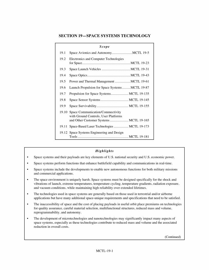
SECTION 19—SPACE SYSTEMS TECHNOLOGY
Scope
19.1 Space Avionics and Autonomy....................MCTL 19-5
19.2 Electronics and Computer Technologiesfor Space............................................... MCTL 19-23
19.3 Space Launch Vehicles ............................ MCTL 19-31
19.4 Space Optics.......................................... MCTL 19-43
19.5 Power and Thermal Management ............... MCTL 19-61
19.6 Launch Propulsion for Space Systems........ MCTL 19-87
19.7 Propulsion for Space Systems................. MCTL 19-135
19.8 Space Sensor Systems........................... MCTL 19-145
19.9 Space Survivability............................... MCTL 19-155
19.10 Space Communication/Connnectivitywith Ground Controls, User Platformsand Other Customer Systems.................. MCTL 19-165
19.11 Space-Based Laser Technologies .............. MCTL 19-173
19.12 Space Systems Engineering and DesignTools ................................................. MCTL 19-181
Highlights
• Space systems and their payloads are key elements of U.S. national security and U.S. economic power.
• Space systems perform functions that enhance battlefield capability and communications in real-time.
• Space systems include the developments to enable new autonomous functions for both military missionsand commercial applications.
• The space environment is uniquely harsh. Space systems must be designed specifically for the shock andvibrations of launch, extreme temperatures, temperature cycling, temperature gradients, radiation exposure,and vacuum conditions, while maintaining high reliability over extended lifetimes.
• The technologies used in space systems are generally based on those used in terrestrial and/or airborneapplications but have many additional space-unique requirements and specifications that need to be satisfied.
• The inaccessibility of space and the cost of placing payloads in useful orbit place premiums on technologiesfor quality assurance, careful material selection, multifunctional structures, reduced mass and volume,reprogrammability, and autonomy.
• The development of microtechnologies and nanotechnologies may significantly impact many aspects ofspace systems, especially as these technologies contribute to reduced mass and volume and the associatedreduction in overall costs.
(Continued)

MCTL-19-2
Highlights (Continued)
• Improving the prediction accuracy of space devices, components, or systems required significantly improvedmodels for gauging the response of electronics, microelectronics, sensors, and other photonic systems in thespace environment.
• Laser communications in space and from space may revolutionize the battlefield command and controlcapabilities as well as future commercial ventures.
• Because of the increasing availability and capabilities of COTS technologies, there is a current andcontinuing emphasis within the space industry to use COTS products in space and launch vehicleapplications in place of unique, custom radiation hardened designs.
OVERVIEW
Militarily Critical Space Technologies included in this section are only those technologies, which are unique tospace applications, payloads, platforms, and military space missions, including technologies required for launchingassets into space and space surveillance applications. Each space technology listed in this section has specific goals,which include:
• Reducing the cost of access to space and the cost of space assets by innovative engineering and weightreduction techniques;
• Improving technologies which enable space missions and systems applications to function for long timeframes and enable ambitious future space missions and systems applications;
• Providing significant technological improvements and higher efficiencies for Space Superiority; and
• Improving the battlefield command and control with real-time communications.
Technology for space platforms includes not only the technologies related to space sensors, experimentalapparatuses, electronics, communications, information handling, and data analysis, but also those technologiesnecessary for the spacecraft and launch systems (e.g., spacecraft power, launch vehicles, control and structuralsystems, and propulsion). The space sciences have traditionally used new and modified technologies to enable moreambitious missions. The commercial industries, the National Aeronautics and Space Administration (NASA), andthe U.S. military complex have developed many technologies for unique and complex space applications. A quicklook at space launch and spacecraft technologies illustrates the range of disciplines and functional areas for whichspace-unique technologies are required. These include items such as orbital mechanics, launch and transferpropulsion, launch and space vehicles, environmental protection, structures and packaging constraints, stability andcontrol, thermal control, data and voice communications, power generation and distribution, sensors andinstrumentation, electronics and computer processors, remote sensors, and ground station interfaces.
In addition to the obvious military applications, space technologies have made possible the current scientificconcept of the earth as a complex system. From Apollo photographs of the earth as a blue marble to the recentshuttle-based radar images of rain tracks in the Midwest or ancient drainage structures under Middle Eastern deserts,the space perspective has revolutionized our understanding of atmospheric, oceanic, and land processes. Mankind hasmeasured centimeter-scale distortions of the earth’s crust associated with plate tectonics; detected and monitored thepolar ozone holes; begun to understand the dynamics and chemistry of the stratosphere and upper atmosphere;correlated climate variations with the Pacific El Niño and La Niña and with major volcanic eruptions; learned to usesatellite radiometry to estimate global atmospheric temperature and moisture profiles; bounded solar variability;measured the components of the earth’s radiation; and used satellite observations to validate greatly improvedatmospheric models for prediction of weather and climate.
In recent years, NASA’s emphasis on operations has increased while its pursuit of new technology hasnarrowed to focus on specific mission needs. The new 2004 NASA space imperative places increased emphasis onthe International Space Station, using the moon as a base for interplanetary missions, and enabling humanexploration of Mars. Meanwhile, the Department of Defense (DoD) has continued to fund industry, academia, and

MCTL-19-3
government laboratories to develop a broad range of space technologies. Consequently, DoD has become the primaryagent of technological advancement, and industry and academia have become the primary U.S. developers of newspace technologies. Many space-based sensors used today were developed through the collaborative efforts ofindustry/university/national laboratories and are based on DoD technologies.
Many space technologies are unique because of specifications and the specific technical parameters required for agiven space application and because they have been developed to withstand the conditions and parameters of thehighly ionized space environment. For a system to get to space, it first must endure the shock, vibrations, and forcesof launch. Once in space, it is often subjected to rapid and continuous cycling between the extremes of heat and cold,to high internal temperature gradients, and to constant high energy radiation and particle bombardment—especiallythat of atomic oxygen. Space assets are generally inaccessible for upgrade or maintenance and, thus, must be capableof operating reliably for their design life.
The inaccessibility of space and the cost of placing payloads into useful orbit dictate several additionalconsiderations for space technologies. Miniaturization reduces the size and weight of the payload that must beboosted into orbit and reduces system power-consumption and heat-management requirements. Therefore, themotivation to reduce the size and power requirements of space assets is strong and has initiated many newmicrotechnologies and nanotechnologies specifically developed for space applications.
Quality assurance programs can test systems in the laboratory, and simulations can be used to improve thelikelihood that the systems will perform properly after being placed in space. However, laboratory quality assurancetesting must be conducted with caution since simulations of physical parameter effects must be performed in aconcurrent fashion. For example, researchers now know that radiation exposure and atomic oxygen exposure areabout 10 times more damaging (corrosively) when an item is exposed to them concurrently than when the same itemis exposed to them separately. Materials must also be carefully selected to minimize out-gassing in space or tomitigate its impacts. All these “assurances” must be observed during the development of space technologies toensure reliability. In addition, the development of reprogrammability and autonomy, which can provide self-governing or allow commanding from ground controllers, will allow space systems to be adapted to new or changingrequirements.
Space sensors are required for many military and commercial missions including weather surveillance,monitoring crops, target surveillance and battlefield management to name a few. In recent years, space surveillancehas become a major commercial venture with many companies participating. The military has also stepped up itsuse of space surveillance to spot targets of opportunity and along with GPS improve the guidance of missilesystems and precision munitions.
Space launch and space propulsion technologies have also improved significantly over the past few years withhigher specific impulse (Isp) and improved thrust for both launch and inter-orbit activities. There are now manycountries involved with developing improved space launch vehicles and propulsion mechanisms that will be outlinedin this section.
A new arena has unfolded in both space and terrestrial applications using micro and especially nano-technologies. By using structures at the nanoscale, it is possible to greatly expand the range of performance ofexisting chemicals and materials. Scientists can already foresee using patterned monolayers for a new generation ofchemical and biological sensors; nanoscale switching devices to improve computer storage capacity by a factor of amillion; tiny medical probes that will not damage tissues; entirely new drug and gene delivery systems;nanostructured ceramics, polymers, metals, and other materials with greatly improved mechanical properties;nanoparticle reinforced polymers in lighter cars; and nanostructured silicates and polymers as better contaminantscavengers for cleaner designs and fabrication of complex nanoscale assemblies. Most of these technologies will firstbe developed for terrestrial applications and then modified for space systems.
All of these technologies including the micro and nano-technology lead to significant reduction of mass forspace applications, and some predict that nanotechnology will lead the way for the 21st century space applications.The broad scope of developing new and improved space technologies must include the National NanotechnologyInitiative (NNI) announced by the President in February 2000. A September 1999 report by the administration’s

MCTL-19-4
National Science and Technology Council (NSTC) and the Interagency Working Group (IWG) on Nanoscience,Engineering and Technology, summarizes the prospects for nanoscale science and engineering (NS&E).
Microtechnologies and nanotechnologies will not only provide size, weight, power, and thermal managementbenefits, but they also promise far greater functionality and higher operating speeds. Microelectro-mechanicalsystems (MEMS) and micro-optoelectro-mechanical systems (MOEMS) are experiencing tremendous growth. Thesetechnologies use optics, electronics, and mechanics in miniaturized space applications. According to a NationalAcademy of Engineering (NAE) symposium report, MEMS and MOEMS technologies have opened many newopportunities for optics, electronics, and micropositioning equipment, especially as these pertain to spaceapplications. For the first time, reliable microactuators and three-dimensional (3-D) optomechanical structures can bemonolithically integrated with microoptical elements. MEMS and MOEMS technologies have also made possible,the integration of an entire optical table onto a single silicon chip. This capability translates to smaller, lighter, andmore cost-effective space payload launches and will impact many space applications, including positioning,scanning, and telecommunications.
For many radiation-intensive applications, such as deep space, strategic environments, and mid-earth orbits(MEO), the electronics have traditionally been produced using silicon foundry processes and Very Large ScaleIntegration (VLSI) design techniques that were specifically designed for non-standard (i.e., “non-COTS”) radiationhardened components. As Moore’s law continues to hold, and computer power per unit size continues to shrink,foundries dedicated to terrestrial applications and COTS continue to improve. The influence of COTS technologieson space systems is significant. Radiation hardened technologies are no longer limited to device and componentlevel, and specific radiation-hardened components may not be needed. Rather, technologies such as shielding andhardening at the case level may enable reliable and long-lived operation of COTS products in space. Othertechniques, such as incorporating redundant COTS units, using improved error detecting and correcting software, andrelying on the radiation protection inherent in smaller feature sizes and improved designs of newer COTStechnologies, can also be used. Use of photonics devices for intra- and inter-component communications wouldenhance electrical isolation and mitigate impacts of individual faults, while enabling higher speed interconnects.Clearly, however, a combination of technologies in an overall systems design will allow increased use of COTScomponents and subsystems in space system today and into the future.
In summary, each space technology development program or strategic plan—whether at NASA, DoD, orcommercial firms—has specific goals. The common goals of all members of the space technology communityinclude the four items mentioned in the first paragraph of this section as well as:
• Building capability in the U.S. space military/industry complex through collaborative and focused spacetechnology development efforts
• Sharing the results of space technology R&D with the rest of the U.S. space community.

MCTL-19-5
SECTION 19.1—SPACE AVIONICS AND AUTONOMY
Highlights
• Major advances in timing: Next-generation, space-qualified clocks will be several orders of magnitude morestable < 1 × 10–15 per day).
• Absolute positioning of a space vehicle/platform to < 10 m accuracy is now achievable with relativeposition control to < 1 m.
• Contingency operations can be enacted in < 0.1 second with new space qualified processors, which candetect an anomaly, determine when it can be corrected to either restore capability or eliminate the chance ofdomino effects.
• New processors and algorithms enable autonomous operation of “clusters” of microsatellites ornanosatellites to < 1 mm in all three dimensions.
• Higher satellite acceleration sensitivity, < 0.001 g’s, is now achievable.
• It now takes < 2 seconds reaction time to decompose a set of high-level objectives, incorporate locallydetermined information, and create an execution plan autonomously.
• One can now demonstrate a “weapon safing” class of response in < 0.01 second.
• Absolute orbital position or ephemeris calculation on-board at Low-Earth Orbit (LEO) to < 5 m.
• MEMS technology will significantly improve existing functions to be performed in smaller sized packagesand will replace and enable entirely new categories of functions.
• Space autonomy has significantly improved allowing spacecraft to fly in formation or to operate/maneuveraround a space object.
• Determination of position and attitude relative to another space object to < 3 m when within 200 m range isnow possible.
OVERVIEW
Technologies identified in this section support navigation, attitude control, orbit determination, space vehicledynamics, autonomy and other similar avionics functions unique to space systems. To perform their functionsproperly, space vehicles must navigate through space; orient their sensors, antennas, solar panels, and other systemsproperly; monitor and control their dynamics; and determine their orbits and necessary corrections. For the most part,technologies to support these avionics functions in space systems are similar to those used in aircraft avionics. Thespace environment often requires that technologies be modified significantly from their airborne or terrestrialcounterparts. One example is space-qualified a tomic f requency s tandards (AFSs) or “clocks.” While the basic referenceatomic element and the quartz oscillator may be very similar to their terrestrial counterparts, the electronics controlpackage and elements of the physics package for operation in zero gravity and stabilizing the internal environmentare entirely different. The high radiation environment and very high velocities also require unique solutions to similarproblems on aircraft.
BACKGROUND
The DoD and NASA have utilized space for many applications. These range from space surveillance ofadversaries moves and locations, to space communications and navigation, or to the understanding of weatherpatterns and movements. Many commercial space ventures have also developed over the past 30 years. Space has

MCTL-19-6
become a required arm of the new battlefield for modern warfare. As such, some space technologies have becomemilitarily critical for various aspects of war fighting and battlefield management.
The space environment provides unique technology requirements as well as opportunities, which in some casesare significantly different from their terrestrial complements. For example, precisely determining inertial attitude inspace by means of “star trackers,” or gyro-astro trackers is possible because these trackers do not have to contendwith distortion caused by the earth’s atmosphere. However, they have to constantly correct for orbit fluctuations andother space unique attributes. Only those avionics and autonomy technologies that have unique space aspects orunique technical differences in the critical parameter set for space applications are included in this section. See MCTLSection 16, Positioning, Navigation, and Time, for additional and complementary airborne and terrestrialtechnologies in these disciplines.
MCTL-19-7
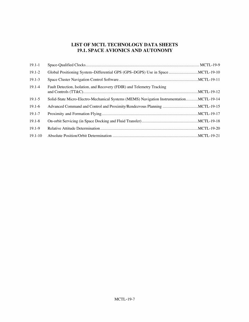
LIST OF MCTL TECHNOLOGY DATA SHEETS19.1. SPACE AVIONICS AND AUTONOMY
19.1-1 Space-Qualified Clocks............................................................................................. MCTL-19-9
19.1-2 Global Positioning System–Differential GPS (GPS–DGPS) Use in Space........................MCTL-19-10
19.1-3 Space Cluster Navigation Control Software.................................................................MCTL-19-11
19.1-4 Fault Detection, Isolation, and Recovery (FDIR) and Telemetry Trackingand Controls (TT&C)..............................................................................................MCTL-19-12
19.1-5 Solid-State Micro-Electro-Mechanical Systems (MEMS) Navigation Instrumentation..........MCTL-19-14
19.1-6 Advanced Command and Control and Proximity/Rendezvous Planning .............................MCTL-19-15
19.1-7 Proximity and Formation Flying...............................................................................MCTL-19-17
19.1-8 On-orbit Servicing (in Space Docking and Fluid Transfer) ..............................................MCTL-19-18
19.1-9 Relative Attitude Determination................................................................................MCTL-19-20
19.1-10 Absolute Position/Orbit Determination ......................................................................MCTL-19-21
MCTL-19-9
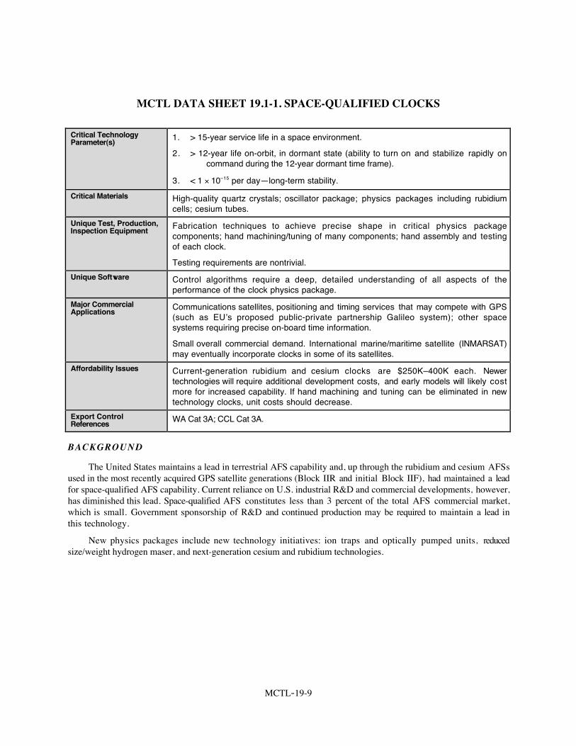
MCTL DATA SHEET 19.1-1. SPACE-QUALIFIED CLOCKS
Critical TechnologyParameter(s) 1. > 15-year service life in a space environment.
2. > 12-year life on-orbit, in dormant state (ability to turn on and stabilize rapidly oncommand during the 12-year dormant time frame).
3. < 1 × 10–15 per day—long-term stability.Critical Materials High-quality quartz crystals; oscillator package; physics packages including rubidium
cells; cesium tubes.Unique Test, Production,Inspection Equipment Fabrication techniques to achieve precise shape in critical physics package
components; hand machining/tuning of many components; hand assembly and testingof each clock.
Testing requirements are nontrivial.Unique Software Control algorithms require a deep, detailed understanding of all aspects of the
performance of the clock physics package.Major CommercialApplications Communications satellites, positioning and timing services that may compete with GPS
(such as EU’s proposed public-private partnership Galileo system); other spacesystems requiring precise on-board time information.
Small overall commercial demand. International marine/maritime satellite (INMARSAT)may eventually incorporate clocks in some of its satellites.
Affordability Issues Current-generation rubidium and cesium clocks are $250K–400K each. Newertechnologies will require additional development costs, and early models will likely costmore for increased capability. If hand machining and tuning can be eliminated in newtechnology clocks, unit costs should decrease.
Export ControlReferences WA Cat 3A; CCL Cat 3A.
BACKGROUND
The United States maintains a lead in terrestrial AFS capability and, up through the rubidium and cesium AFSsused in the most recently acquired GPS satellite generations (Block IIR and initial Block IIF), had maintained a leadfor space-qualified AFS capability. Current reliance on U.S. industrial R&D and commercial developments, however,has diminished this lead. Space-qualified AFS constitutes less than 3 percent of the total AFS commercial market,which is small. Government sponsorship of R&D and continued production may be required to maintain a lead inthis technology.
New physics packages include new technology initiatives: ion traps and optically pumped units, reducedsize/weight hydrogen maser, and next-generation cesium and rubidium technologies.

MCTL-19-10
MCTL DATA SHEET 19.1-2. GLOBAL POSITIONING SYSTEM–DIFFERENTIAL GPS(GPS–DGPS) USE IN SPACE
Critical TechnologyParameter(s) The following are considered critical military parameter levels for GPS-DGPS
components/systems:
1. Absolute positioning of space vehicle to < 10 m accuracy.
2. Timing to < 1 ns (10-9 seconds) accuracy.
3. Relative timing synchronization to < 10 ps (10-11 seconds).
4. Relative positioning of one space vehicle operating with other(s) to < 1 m.Critical Materials None identified.Unique Test, Production,Inspection Equipment GPS/DGPS antenna/receiver calibration.
Unique Software RTK and other error-reduction processing, in particular for DGPS-based relativepositioning and timing among clusters of cooperatively operating, independent spacevehicles.
Major CommercialApplications Auto-navigation of constellations of satellites for various purposes. Smaller satellites,
with less space/weight needed for positioning and attitude control.Affordability Issues This technology should reduce the cost of positioning and attitude control for small
satellites and/or spacecraft in lower orbits.Export ControlReferences WA ML11; WA Cat 7A, 7D and 7E; MTCR 11; CCL Cat 7A, 7D and 7E.
BACKGROUND
GPS technology is currently revolutionizing positioning, navigation, and time dissemination in airborne andterrestrial applications. It provides a worldwide position and time (or POSITIME) grid, which forms the basis formaps and for static and dynamic geographic information systems. It also reduces the need for carrying extraequipment when access to the GPS POSITIME information is available. GPS enables the coherent combination ofinformation from multiple sensors and the sharing of information among cooperating weapon systems andplatforms.
MCTL-19-11
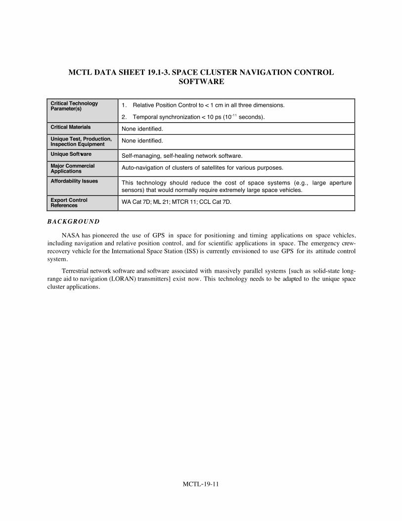
MCTL DATA SHEET 19.1-3. SPACE CLUSTER NAVIGATION CONTROLSOFTWARE
Critical TechnologyParameter(s) 1. Relative Position Control to < 1 cm in all three dimensions.
2. Temporal synchronization < 10 ps (10-11 seconds).Critical Materials None identified.Unique Test, Production,Inspection Equipment None identified.
Unique Software Self-managing, self-healing network software.Major CommercialApplications Auto-navigation of clusters of satellites for various purposes.
Affordability Issues This technology should reduce the cost of space systems (e.g., large aperturesensors) that would normally require extremely large space vehicles.
Export ControlReferences WA Cat 7D; ML 21; MTCR 11; CCL Cat 7D.
BACKGROUND
NASA has pioneered the use of GPS in space for positioning and timing applications on space vehicles,including navigation and relative position control, and for scientific applications in space. The emergency crew-recovery vehicle for the International Space Station (ISS) is currently envisioned to use GPS for its attitude controlsystem.
Terrestrial network software and software associated with massively parallel systems [such as solid-state long-range aid to navigation (LORAN) transmitters] exist now. This technology needs to be adapted to the unique spacecluster applications.
MCTL-19-12
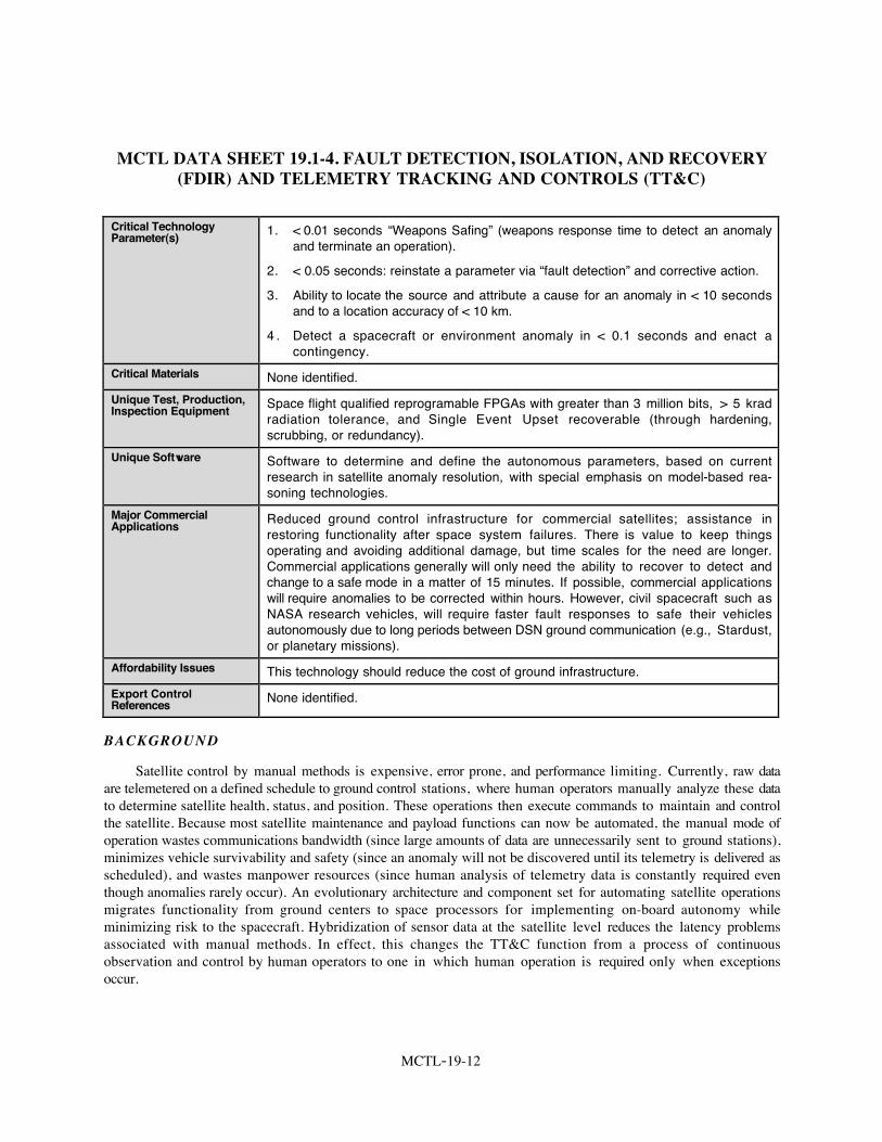
MCTL DATA SHEET 19.1-4. FAULT DETECTION, ISOLATION, AND RECOVERY(FDIR) AND TELEMETRY TRACKING AND CONTROLS (TT&C)
Critical TechnologyParameter(s) 1. < 0.01 seconds “Weapons Safing” (weapons response time to detect an anomaly
and terminate an operation).
2. < 0.05 seconds: reinstate a parameter via “fault detection” and corrective action.
3. Ability to locate the source and attribute a cause for an anomaly in < 10 secondsand to a location accuracy of < 10 km.
4 . Detect a spacecraft or environment anomaly in < 0.1 seconds and enact acontingency.
Critical Materials None identified.Unique Test, Production,Inspection Equipment Space flight qualified reprogramable FPGAs with greater than 3 million bits, > 5 krad
radiation tolerance, and Single Event Upset recoverable (through hardening,scrubbing, or redundancy).
Unique Software Software to determine and define the autonomous parameters, based on currentresearch in satellite anomaly resolution, with special emphasis on model-based rea-soning technologies.
Major CommercialApplications Reduced ground control infrastructure for commercial satellites; assistance in
restoring functionality after space system failures. There is value to keep thingsoperating and avoiding additional damage, but time scales for the need are longer.Commercial applications generally will only need the ability to recover to detect andchange to a safe mode in a matter of 15 minutes. If possible, commercial applicationswill require anomalies to be corrected within hours. However, civil spacecraft such asNASA research vehicles, will require faster fault responses to safe their vehiclesautonomously due to long periods between DSN ground communication (e.g., Stardust,or planetary missions).
Affordability Issues This technology should reduce the cost of ground infrastructure.Export ControlReferences None identified.
BACKGROUND
Satellite control by manual methods is expensive, error prone, and performance limiting. Currently, raw dataare telemetered on a defined schedule to ground control stations, where human operators manually analyze these datato determine satellite health, status, and position. These operations then execute commands to maintain and controlthe satellite. Because most satellite maintenance and payload functions can now be automated, the manual mode ofoperation wastes communications bandwidth (since large amounts of data are unnecessarily sent to ground stations),minimizes vehicle survivability and safety (since an anomaly will not be discovered until its telemetry is delivered asscheduled), and wastes manpower resources (since human analysis of telemetry data is constantly required eventhough anomalies rarely occur). An evolutionary architecture and component set for automating satellite operationsmigrates functionality from ground centers to space processors for implementing on-board autonomy whileminimizing risk to the spacecraft. Hybridization of sensor data at the satellite level reduces the latency problemsassociated with manual methods. In effect, this changes the TT&C function from a process of continuousobservation and control by human operators to one in which human operation is required only when exceptionsoccur.

MCTL-19-13
This technology area provides the components and architecture for autonomous satellite health and statusanalysis and FDIR. With this technology, autonomous satellite operations become the norm and reduce the need forlabor-intensive, human-directed satellite control functions.
MCTL-19-14
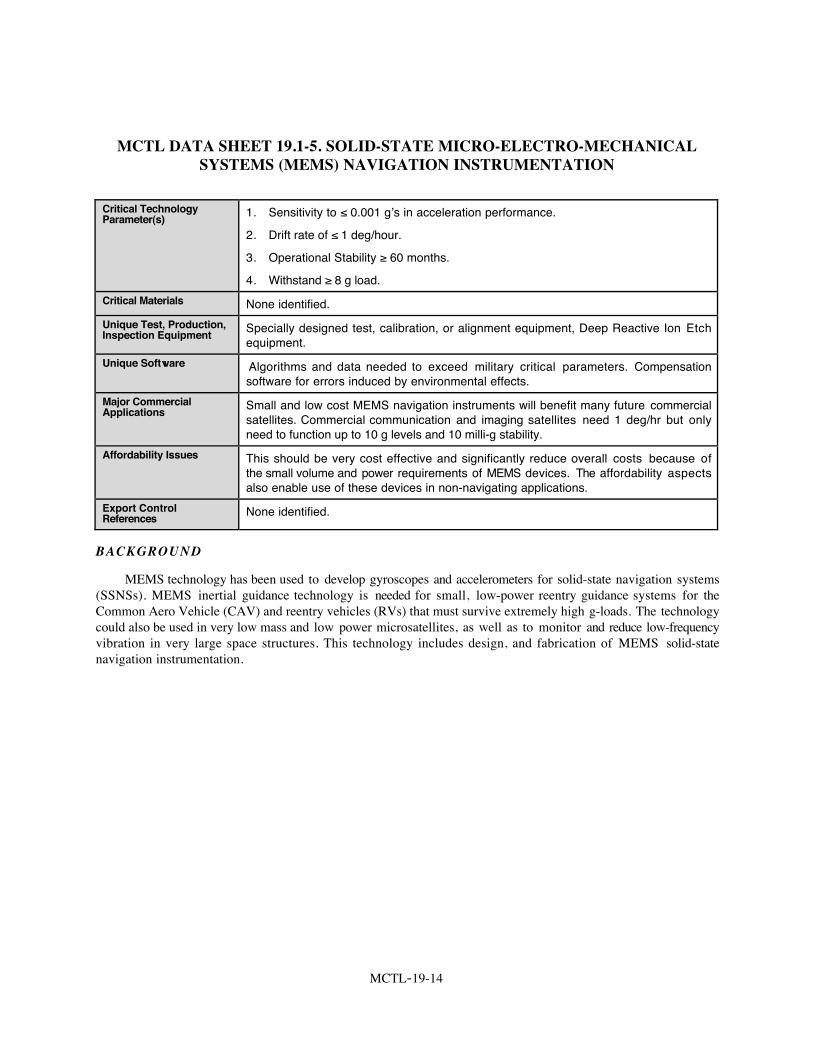
MCTL DATA SHEET 19.1-5. SOLID-STATE MICRO-ELECTRO-MECHANICALSYSTEMS (MEMS) NAVIGATION INSTRUMENTATION
Critical TechnologyParameter(s) 1. Sensitivity to ≤ 0.001 g’s in acceleration performance.
2. Drift rate of ≤ 1 deg/hour.
3. Operational Stability ≥ 60 months.
4. Withstand ≥ 8 g load.Critical Materials None identified.Unique Test, Production,Inspection Equipment Specially designed test, calibration, or alignment equipment, Deep Reactive Ion Etch
equipment.Unique Software Algorithms and data needed to exceed military critical parameters. Compensation
software for errors induced by environmental effects.Major CommercialApplications Small and low cost MEMS navigation instruments will benefit many future commercial
satellites. Commercial communication and imaging satellites need 1 deg/hr but onlyneed to function up to 10 g levels and 10 milli-g stability.
Affordability Issues This should be very cost effective and significantly reduce overall costs because ofthe small volume and power requirements of MEMS devices. The affordability aspectsalso enable use of these devices in non-navigating applications.
Export ControlReferences None identified.
BACKGROUND
MEMS technology has been used to develop gyroscopes and accelerometers for solid-state navigation systems(SSNSs). MEMS inertial guidance technology is needed for small, low-power reentry guidance systems for theCommon Aero Vehicle (CAV) and reentry vehicles (RVs) that must survive extremely high g-loads. The technologycould also be used in very low mass and low power microsatellites, as well as to monitor and reduce low-frequencyvibration in very large space structures. This technology includes design, and fabrication of MEMS solid-statenavigation instrumentation.

MCTL-19-15
MCTL DATA SHEET 19.1-6. ADVANCED COMMAND AND CONTROL ANDPROXIMITY/RENDEZVOUS PLANNING
Critical TechnologyParameter(s) 1. < 2 seconds reaction time to decompose a set of high-level objectives, incorporate
locally determined information, and create an execution plan.
2. Calculate and propagate forward desired orbital position > 1 hour in advance.
3. Execute high level complicated tasking with < 2 ground contacts per day.
4. Continuous operations in proximity to a space object with < 5 m relative positionerror.
5. On-board calculation of trajectories and propulsive maneuvers exceeding 10 m/sor exceeding 2 maneuvers per orbit.
Critical Materials None identified.Unique Test, Production,Inspection Equipment None identified.
Unique Software The command and control of spacecraft can be implemented from ground controlsegments with both currently available commercial packages (EPOCH, SCS21, SCLOS/COMET), or with company proprietary, spacecraft specific, or specialized militaryC2 software.
Improvements over such systems would include software algorithms that predictspacecraft performance in close proximity to other objects, that examine quickly thecapability to maneuver a spacecraft among other on-orbit objects (Resident SpaceObjects or RSOs)., and that account for spacecraft resource utilization against on-orbit position constraints in inertial space, or in RSO proximity.
Major CommercialApplications Commercial applications employ automated systems to reduce needs for interactive
commanding, to simplify determination of commanding actions, and to reduce numbersof people needed in ground control segments. As complexities increase in commercialapplications (e.g., larger satellite constellations, mixed generations of satellites, etc.)or costly problems are experienced, commercial satellite providers may opt for moresophisticated processing capabilities.
This software would also be very useful for long term civil space missions (Pluto,comets, etc.), which often involve international partners.
Affordability Issues Because of the potential to greatly reduce the ground staffing required to operatespacecraft, the potential to reduce mission operational costs is large. One or twooperators will be able to control multiple complex spacecraft.
Export ControlReferences None identified.
BACKGROUND
Coordinated commanding of spacecraft by other spacecraft allows for on-orbit system-like redundancy in certainoperating scenarios (downlink windows, reduced sensor gathering capabilities, etc.). For some systems, closecoordination is required for mission success, such as multiple spacecraft interferometry missions. Because of thedemand within the civil space community to employ these techniques for space and earth imaging, whichincreasingly involves international partnerships, protection of this technology presents challenges.

MCTL-19-16
This technology supports and automates complex satellite control and command functions, addressescomplicated problems with multiple objectives, manages competition for resources and dynamic operationalenvironments, and simultaneously optimizes the allocation and scheduling of space-based resources. The approachincludes algorithms and software for streamlined connectivity such as satellite IP node interfaces, centralized anddistributed control techniques. Examples include a single satellite commanding a cluster, real-time distributed sensingand response among satellites in a cluster, (e.g., one satellite sensing the actions of another and responding), andqueuing appropriate responses and actions in other systems accordingly.

MCTL-19-17
MCTL DATA SHEET 19.1-7. PROXIMITY AND FORMATION FLYING
Critical TechnologyParameter(s) 1. Separation distance between spacecraft: < 200 m.
2. Accuracy of relative navigation, guidance, and control < 3 m when within 200 m.
3 . Location accuracy for all spacecraft: < 20 cm absolute range measurement(Assumes range not obtained from cooperation and communication with object).
4 . Location accuracy for all spacecraft: < 2 mm absolute cooperative rangedetermination (assumes range is between cooperative and communicatingspacecraft).
Critical Materials Lasers with high frequency stability.Unique Test, Production,Inspection Equipment None identified.
Unique Software Algorithms and software for determining of the relative position and attitude of thetarget vehicle and for the planning and control of proximity operations.
Major CommercialApplications There is some commercial opportunity for satellite servicing and inspection that would
use this. Accuracy levels only need to be as good as 3 meters, unless docking; mostcommercial applications will be cooperative or aided in their operations.
Affordability Issues This technology should lower overall operational costs by reducing the need for groundcontrol personnel, and should enable repair of on-orbit assets.
Export ControlReferences None identified.
BACKGROUND
Flying one satellite in close relative proximity to another satellite or flying so as to maintain a desiredseparation or range of separations from other satellite(s) is an enabling capability for inspection and repair of on-orbitassets. This technology includes the ability to plan and execute relative trajectories, methods to determine relativerange and bearing without aid from the object. It also includes methods to effectively and efficiently control therelative position and orientation of satellites. Algorithms for fail-safe maneuvers and planned reaction to faults arealso a part of this technology.
Specific metrics used in this technology include:
1. How close one can safely operate.
2. Accuracy of position information.
3. Responsiveness to events.
4. Degree of cooperation of the other object.
5. Potential damage to the other object from sensors.

MCTL-19-18
MCTL DATA SHEET 19.1-8. ON-ORBIT SERVICING(IN SPACE DOCKING AND FLUID TRANSFER)
Critical TechnologyParameter(s) • The ability to dock/grapple a satellite not designed for servicing
• The ability to transfer fuel (bi-propellant, mono-propellant, and pressurant) acrosssatellites.
• The ability to transfer cryogenic fluid and/or Space-Based “Laser” reactants
• Replacement or upgrade of satellite components
• Accuracy of attitude/position knowledge between satellites as follows:Operating
Range(m)
Range
(mm)
AzimuthElevation(Radians){Degrees}
Roll
(Radians){Degrees}
Pitch/Yaw
(Radians){Degrees}
1–3 ± 12 ± 0.00058{± 0.033}
± 0.00227{± 0.13}
± 0.00349{± 0.2}
> 3–5 ± 35 ± 0.00058{± 0.033}
± 0.00436{± 0.25}
± 0.00576{± 0.33}
> 5–10 ± 150 ± 0.00061{± 0.035}
± 0.00785{± 0.45}
± 0.01222{± 0.7}
> 10–30 ± 1500 ± 0.00065{± 0.037}
± 0.02269{± 1.3}
± 0.0349{± 2}
> 30–50 ± 400 ± 0.00052{± 0.03}
± 0.00436{± 0.25}
± 0.02094{± 1.2}
> 50–100 ± 1666 ± 0.00058{± 0.033}
± 0.00873{± 0.5}
± 0.04189{± 2.4}
> 100–300 ± 15,000 ± 0.00061{± 0.035}
± 0.02443{± 1.4}
± 0.12217{± 7.0}
Critical Materials None identified.Unique Test, Production,Inspection Equipment None identified.
Unique Software Sensor Processing—Process sensor data to determine the relative range, azimuth,roll, pitch, and yaw of the target vehicle.
Autonomous Navigation—Ability to integrate inertial and other sensor data to determinerelative position, velocity, and attitude rates of the target vehicle.
Autonomous Guidance—Algorithms to maneuver a spacecraft inside a cone whiletraversing an approach or separation vector with velocity limits relative to the targetsbody coordinates. Algorithms to allow a spacecraft to station-keeping relative to thetargets body coordinates.
Major CommercialApplications Routine automated on-orbit satellite servicing; refueling and selected bus/payload
equipment upgrades can extend the useful lifetime of satellites and reduce life cyclecosts. Docking is a critical requirement for servicing or refueling operations.
Affordability Issues On-Orbit satellite servicing has been studied and shown to reduce the life cycle costsof both military and commercial space programs.
Export ControlReferences None identified.

MCTL-19-19
BACKGROUND
On-orbit space assets are expensive. The ability to dock with them will enable options to upgrade components,repair failed components, or transfer fuel. Thus, this technology supports extending the life of such assets.
MCTL-19-20
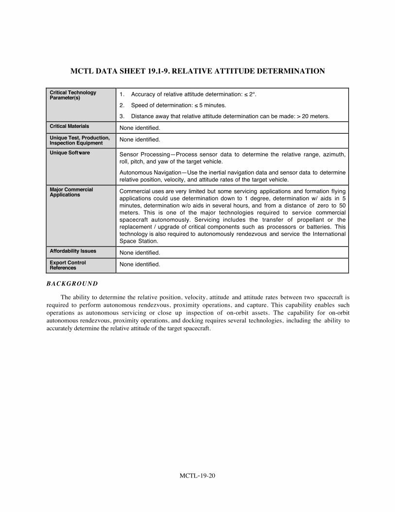
MCTL DATA SHEET 19.1-9. RELATIVE ATTITUDE DETERMINATION
Critical TechnologyParameter(s) 1. Accuracy of relative attitude determination: ≤ 2°.
2. Speed of determination: ≤ 5 minutes.
3. Distance away that relative attitude determination can be made: > 20 meters.Critical Materials None identified.Unique Test, Production,Inspection Equipment None identified.
Unique Software Sensor Processing—Process sensor data to determine the relative range, azimuth,roll, pitch, and yaw of the target vehicle.
Autonomous Navigation—Use the inertial navigation data and sensor data to determinerelative position, velocity, and attitude rates of the target vehicle.
Major CommercialApplications Commercial uses are very limited but some servicing applications and formation flying
applications could use determination down to 1 degree, determination w/ aids in 5minutes, determination w/o aids in several hours, and from a distance of zero to 50meters. This is one of the major technologies required to service commercialspacecraft autonomously. Servicing includes the transfer of propellant or thereplacement / upgrade of critical components such as processors or batteries. Thistechnology is also required to autonomously rendezvous and service the InternationalSpace Station.
Affordability Issues None identified.Export ControlReferences None identified.
BACKGROUND
The ability to determine the relative position, velocity, attitude and attitude rates between two spacecraft isrequired to perform autonomous rendezvous, proximity operations, and capture. This capability enables suchoperations as autonomous servicing or close up inspection of on-orbit assets. The capability for on-orbitautonomous rendezvous, proximity operations, and docking requires several technologies, including the ability toaccurately determine the relative attitude of the target spacecraft.

MCTL-19-21
MCTL DATA SHEET 19.1-10. ABSOLUTE POSITION/ORBIT DETERMINATION
Critical TechnologyParameter(s) 1. < 5 m LEO determination within 10 minutes.
2. < 50 m uncertainty in predicted position for LEO orbits, during any 6-hour period.
3. < 150 m uncertainty in real-time position determination for GEO or HEO (e.g.,above GPS orbits).
Critical Materials None identified.Unique Test, Production,Inspection Equipment Testing must be performed with high-fidelity RF signal simulators with receivers in the
loop and realistic modeling of the ionosphere, multipath, and the orbital environment.Unique Software Multi-source estimation algorithms (which include orbit dynamic models/propagators
with high-fidelity models of all relevant disturbances—solar, ionospheric, atmospheric,high-order gravity, etc.) to combine GPS with other sensor outputs and tracking data.Integrated tracking loops with advanced filtering algorithms to enable weak signaltracking.
Major CommercialApplications Commercial remote sensing spacecraft. All spacecraft, which require geopositioning of
image on Earth. Accuracy for commercial applications < 100 m and predictions within1 km over 24-hour period.
Wide commercial demand.Affordability Issues High-end DoD GPS grade receivers are $250k and above, but a flurry of highly capable
receivers are entering the market in the $10K–$25K regime. Weak signal trackingcapabilities for higher altitude and high Doppler applications will drive up cost.
Export ControlReferences None identified.
BACKGROUND
The ability to estimate position, accurately and in real-time, is essential for many satellite operations. This isparticularly true for earth observing satellites, especially if data from multiple sensors on multiple platforms are tobe integrated into a common operational picture. For some satellites systems, such as military GPS or similar civilposition (or time) dissemination systems (including GEOs augmenting GPS, such as in the Federal AviationAdministration’s Wide Area Augmentation System, or WAAS), precise knowledge of satellite position is essentialto system accuracy. Finally, for docking, rendezvous, or simply situational awareness, accurate knowledge of eachspace asset’s current and predicted position is very important.

MCTL-19-23
SECTION 19.2—ELECTRONICS AND COMPUTER TECHNOLOGIES FOR SPACE
Highlights
• Radiation hardened data processing microelectronics and photonics are required for the manufacture ofsurvivable space and missile systems.
• Commercial Off-The-Shelf (COTS) technologies may be used to build flyable space and launch systems.
• Processing and radiation performance are critical criteria of electronics components and flight computerscomprised of those components.
• Critical parameters are fault coverage, overhead processing load, and latency.
• Photonics technologies provide high-speed interconnects between electronic processors and on-boardcommunications for space systems.
• Critical parameters for photonics interconnect technologies include inherent radiation tolerance and data rateover short distances (< 1 km).
OVERVIEW
This section covers electronics and computing technologies for space systems. Because of the high costs anddifficulties of getting payloads into space, critical electronics systems, subsystems, and components must be assmall and light, and thermally efficient, as possible. Because of the inaccessibility of space systems once in orbit,and to survive the forces of launch and orbit insertion, these technologies must produce systems that are extremelyrugged and reliable. This section includes datasheets on the following technologies:
• Space Flight Computer and Component Technologies include radiation hardened electronics,microelectronics and very large scale integrated circuits (VLSI), and flight computers and components.These technologies are combined in one datasheet because of the influence of commercial off-the-shelf(COTS) technologies.
• Fault Tolerant Computing Technologies include use of protective redundancy to enhance dependability,automated capability to detect and correct hardware and software faults, and capabilities to recover from suchfaults and continue mission performance. Fault tolerance technologies may be implemented in hardware,software, or firmware, which may be upgradeable over the mission duration.
• Photonics Technologies include semiconductor lasers, photodiodes, and related optical components, similarto those used in consumer digital video disc (DVD) players, to provide interconnects within and betweenelectronic processors and other on-board systems in space.
Because of the increasing availability and capabilities of COTS technologies, there is a current and continuingemphasis within the space industry to use COTS products in space and launch vehicle applications in place ofunique, custom radiation hardened designs.
BACKGROUND
Space systems perform functions and use technologies in a manner similar to terrestrial and airborne systems.However, because of the difficulty of getting to space and the harshness of the overall space environment, spacesystems must be specifically designed for stringent criteria, which include:
• extreme levels of acceleration, vibration, shock, and other forces of launch;

MCTL-19-24
• rapid and continuous cycling from extreme heat to extreme cold, and often extreme internal temperaturegradients between “hot” solar facing and “cool” sides;
• high levels of electron, proton, ion, and atom (such as atomic oxygen), and X-ray, gamma ray, and neutronradiation in a nuclear-engendered environment; and
• high reliability—long life, redundancy of critical elements, and generally the inability to service them oncein operation.
During the launch operation, the space system is a payload in the launch vehicle. It will generally be dormantor in state of suspended operations. On reaching space, the system must be capable of being activated and performingits mission as designed.
To survive and operate within the radiation environment of space, electronics and computers at the system andcomponent level must be designed to survive and operate over the planned lifetime. For many radiation-intensiveapplications, such as deep space, strategic environments, and mid-earth orbits (MEO), the electronics havetraditionally been produced using silicon foundry processes and VLSI design techniques that were specificallydesigned for non-standard (i.e., “non-COTS”) radiation hardened components. Those components and foundriesgenerally had no terrestrial application, and as a result, they were costly to obtain and maintain. In general, theylagged several generations behind terrestrial technology in feature size and other capabilities, often because thefoundries themselves were fully depreciated terrestrial assets superseded by newer technology. They were thenconverted and dedicated to radiation hardened technologies.
As Moore’s law continues to hold, and computer power per unit size continues to shrink, foundries dedicated toterrestrial applications and COTS continue to improve. COTS technology is thus continually miniaturized.Miniaturization, due to mostly these smaller feature sizes in electronics but also to software improvements, allowscurrent functions to be accomplished in smaller components and enables development of new functions withinexisting size and power constraints. Miniaturization thus has an increasing benefit for space systems; smaller size(and corresponding reductions in weight and power) enables less expensive space systems or space systems withgreater functionality for a given size. Using new software to enable reprogramming from the ground while on orbit,operators might adapt these smaller, more capable systems in the future for new or changed functions.
The influence of COTS technologies on space systems is significant. Radiation hardened technologies are nolonger limited to device and component level, and specific radiation-hardened components may not be needed. Rather,technologies such as shielding and hardening at the case level may enable reliable and long-lived operation of COTSproducts in space. Other techniques, such as incorporating redundant COTS units, using improved error detecting andcorrecting software, and relying on the radiation protection inherent in smaller feature sizes and improved designs ofnewer COTS technologies, can also be used. Use of photonics devices for intra- and inter-componentcommunications would enhance electrical isolation and mitigate impacts of individual faults, while enabling higherspeed interconnects. Clearly, however, a combination of technologies in an overall systems design will allowincreased use of COTS components and subsystems in space system today and into the future.
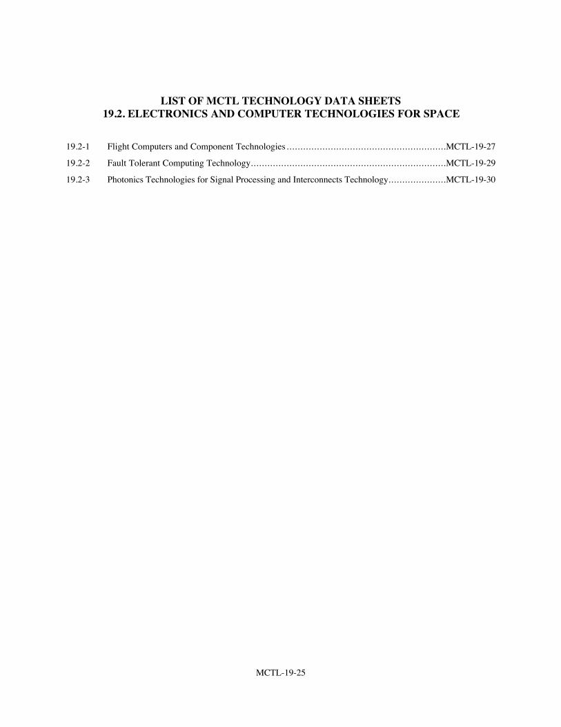
MCTL-19-25
LIST OF MCTL TECHNOLOGY DATA SHEETS19.2. ELECTRONICS AND COMPUTER TECHNOLOGIES FOR SPACE
19.2-1 Flight Computers and Component Technologies ..........................................................MCTL-19-27
19.2-2 Fault Tolerant Computing Technology.......................................................................MCTL-19-29
19.2-3 Photonics Technologies for Signal Processing and Interconnects Technology.....................MCTL-19-30

MCTL-19-27
MCTL DATA SHEET 19.2-1. FLIGHT COMPUTERS AND COMPONENTTECHNOLOGIES
Critical TechnologyParameter(s) Total dose > 5 × 10⁵ Rads (Si).
Dose rate upset > 5 × 10⁸ Rads (Si)/sec.
Neutron dose > 1 × 10¹⁴ N/cm3.
Single event upset of < 1 × 10⁻⁷ errors/bit/day.
Single event latch-up free at dose rate > 5 × 10⁸ Rads (SI)/sec.Critical Materials Silicon, compound semiconductors, silicon-on-insulator material, silicon on sapphire,
aluminum, tungsten carbide, etc.Unique Test, Production,Inspection Equipment None identified.
Unique Software Electronic Design Automation (EDA) and Transistor Computer Aided Design (TCAD)software tools specifically developed for design and analysis of radiation hardenedmicroelectronics.
Modeling and Simulation (M&S) computer codes developed specifically to model andsimulate nuclear weapons effects in microelectronics and photonics technologies,including transport codes.
Design tools and techniques to turn commercial off-the-shelf (COTS) designs andsystems meeting radiation-hardened specifications.
Major CommercialApplications Personal computers, engineering works stations, state-of-the-art electronic
entertainment, banking, and other COTS products.Affordability Issues The use of COTS technologies allow more affordable space systems and launch
capabilities. The COTS processing technologies may have to be combined with softwareand system-level fault tolerance techniques to compensate for the lack of inherenthardness of the components, but may still be able to provide flyable systems for spaceapplications
Export ControlReferences WA Cat 3A; CCL Cat 3A; USML Cat XV.
BACKGROUND
Radiation-hardened integrated circuits can withstand a variety of different radiation effects, as follows:
• Total dose—(Ref. 1) The total amount of radiation that an integrated circuit receives over a period of time.It is a cumulative, long-term degradation of the device and is particularly manifest at the gate and field oxideof CMOS semiconductors.
• Dose rate—The speed at which an integrated circuit receives radiation at any given time. The effect of thedose rate pulse is generation of excess charge in a short period of time. Excess charge results when theionizing pulse occurs at a faster rate than can be recombined. These radiation-induced effects can causetemporary effects or catastrophic failures.
• Neutron dose—Radiation given off by radioactive material (e.g., nuclear weapon or cosmic ray inducedneutrons). High dose rates can result in single event upsets (SEU) in an integrated circuit. An SEU isdefined as follows: “Radiation-induced (Ref. 2) errors in microelectronic circuits caused when charged
MCTL-19-28
particles (usually from the radiation belts or from cosmic rays) lose energy by ionizing the medium throughwhich they pass, leaving behind a wake of electron-hole pairs.”
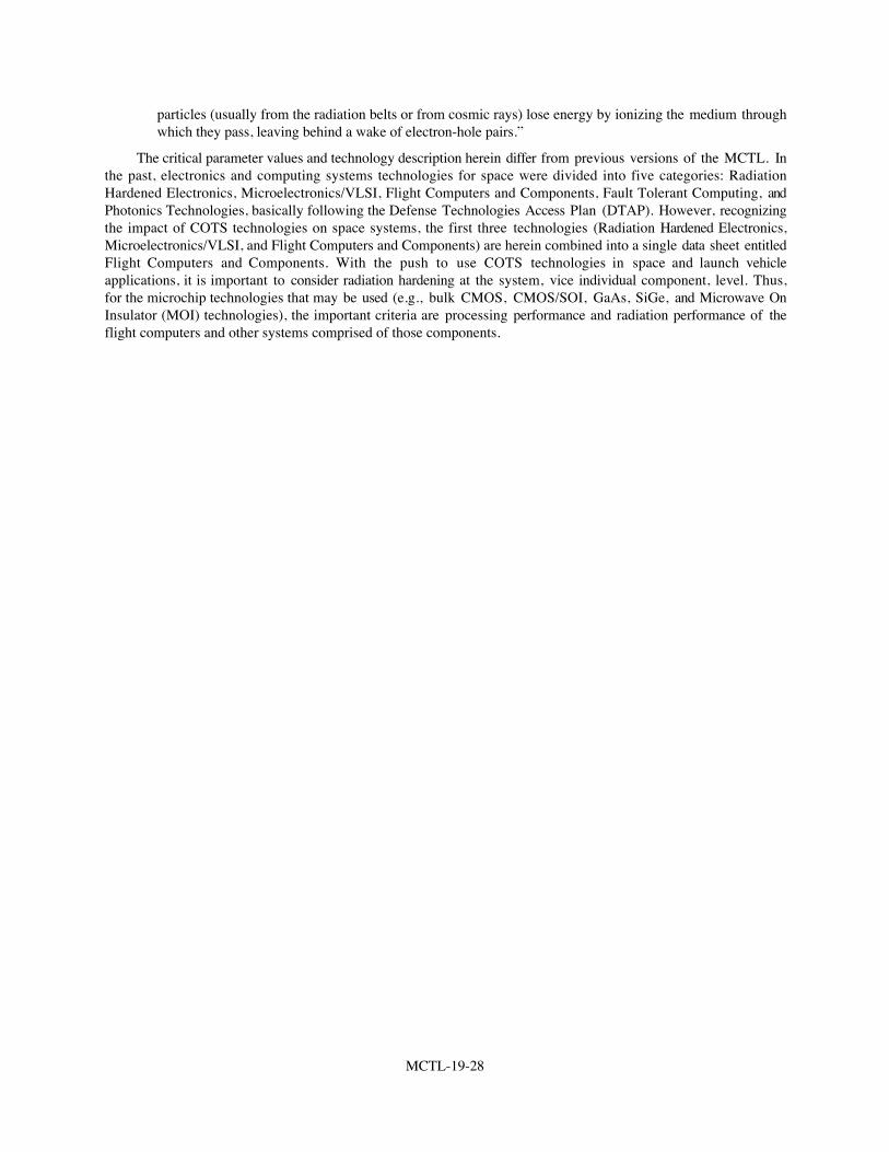
The critical parameter values and technology description herein differ from previous versions of the MCTL. Inthe past, electronics and computing systems technologies for space were divided into five categories: RadiationHardened Electronics, Microelectronics/VLSI, Flight Computers and Components, Fault Tolerant Computing, andPhotonics Technologies, basically following the Defense Technologies Access Plan (DTAP). However, recognizingthe impact of COTS technologies on space systems, the first three technologies (Radiation Hardened Electronics,Microelectronics/VLSI, and Flight Computers and Components) are herein combined into a single data sheet entitledFlight Computers and Components. With the push to use COTS technologies in space and launch vehicleapplications, it is important to consider radiation hardening at the system, vice individual component, level. Thus,for the microchip technologies that may be used (e.g., bulk CMOS, CMOS/SOI, GaAs, SiGe, and Microwave OnInsulator (MOI) technologies), the important criteria are processing performance and radiation performance of theflight computers and other systems comprised of those components.

MCTL-19-29
MCTL DATA SHEET 19.2-2. FAULT TOLERANT COMPUTING TECHNOLOGY
Critical TechnologyParameter(s) Fault Coverage: ≥ 0.999999.
Overhead: ≤ 10% of power, mass, and computing cycles (compared to identical systemwithout the fault tolerance).
Latency: ≤ 1msec.Critical Materials None identified.Unique Test, Production,Inspection Equipment None identified.
Unique Software Software must achieve fault detection, isolation, recovery, and system restorationwithout loss of data and meet real time requirements at peak upset rates.
Major CommercialApplications All commercial satellites and launch vehicles.
Affordability Issues May enable more capability at lower cost if COTS electronics can be used. Tradeoff ishigher nonrecurring cost of redundant equipment and/or fault-tolerant softwaredevelopment.
Export ControlReferences None identified.
BACKGROUND
Fault Tolerance is the use of protective redundancy to enhance the dependability of systems. It is an automatedcapability that allows a circuit, component, module, subsystem, or system to detect and manage hardware and somesoftware faults which would otherwise compromise the ability of the system to properly deliver the expectedservices. Fault tolerance capabilities may be implemented in hardware, software or firmware.
The critical technology parameter is the logical AND of the following sub-parameters: fault coverage(probability of detecting and successfully recovering from a fault), overhead (cost of the fault tolerance capability interms of added power, mass, and computing cycles), and latency (time between occurrence of fault or fault inducederror and completion of fault recovery or return to normal operation).
MCTL-19-30
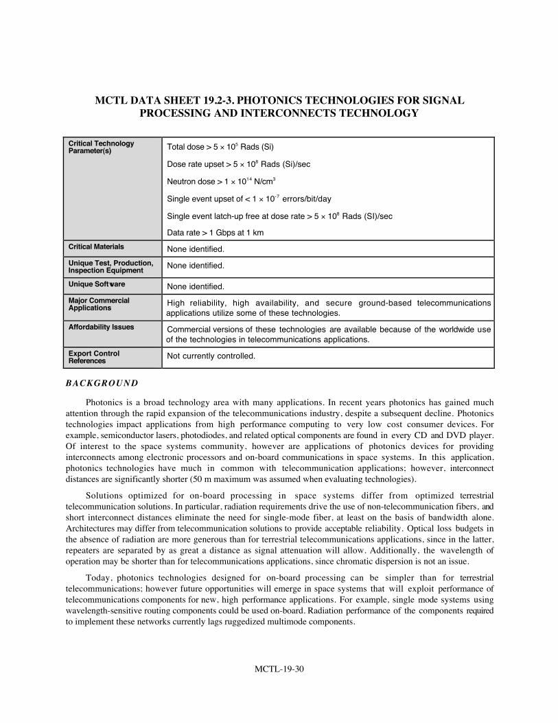
MCTL DATA SHEET 19.2-3. PHOTONICS TECHNOLOGIES FOR SIGNALPROCESSING AND INTERCONNECTS TECHNOLOGY
Critical TechnologyParameter(s) Total dose > 5 × 10⁵ Rads (Si)
Dose rate upset > 5 × 10⁸ Rads (Si)/sec
Neutron dose > 1 × 10¹⁴ N/cm3
Single event upset of < 1 × 10⁻⁷ errors/bit/day
Single event latch-up free at dose rate > 5 × 10⁸ Rads (SI)/sec
Data rate > 1 Gbps at 1 kmCritical Materials None identified.Unique Test, Production,Inspection Equipment None identified.
Unique Software None identified.Major CommercialApplications High reliability, high availability, and secure ground-based telecommunications
applications utilize some of these technologies.Affordability Issues Commercial versions of these technologies are available because of the worldwide use
of the technologies in telecommunications applications.Export ControlReferences Not currently controlled.
BACKGROUND
Photonics is a broad technology area with many applications. In recent years photonics has gained muchattention through the rapid expansion of the telecommunications industry, despite a subsequent decline. Photonicstechnologies impact applications from high performance computing to very low cost consumer devices. Forexample, semiconductor lasers, photodiodes, and related optical components are found in every CD and DVD player.Of interest to the space systems community, however are applications of photonics devices for providinginterconnects among electronic processors and on-board communications in space systems. In this application,photonics technologies have much in common with telecommunication applications; however, interconnectdistances are significantly shorter (50 m maximum was assumed when evaluating technologies).
Solutions optimized for on-board processing in space systems differ from optimized terrestrialtelecommunication solutions. In particular, radiation requirements drive the use of non-telecommunication fibers, andshort interconnect distances eliminate the need for single-mode fiber, at least on the basis of bandwidth alone.Architectures may differ from telecommunication solutions to provide acceptable reliability. Optical loss budgets inthe absence of radiation are more generous than for terrestrial telecommunications applications, since in the latter,repeaters are separated by as great a distance as signal attenuation will allow. Additionally, the wavelength ofoperation may be shorter than for telecommunications applications, since chromatic dispersion is not an issue.
Today, photonics technologies designed for on-board processing can be simpler than for terrestrialtelecommunications; however future opportunities will emerge in space systems that will exploit performance oftelecommunications components for new, high performance applications. For example, single mode systems usingwavelength-sensitive routing components could be used on-board. Radiation performance of the components requiredto implement these networks currently lags ruggedized multimode components.

MCTL-19-31
SECTION 19.3—SPACE LAUNCH VEHICLES
Highlights
• Today’s launch vehicle technology includes significantly larger liquid fueled rockets, smaller solid and liquidfuel motors, and major advances in fuels and motor technologies.
• Payload and upper stage vibro-acoustic mitigation technologies significantly reduce vibration and acousticloading during launch.
• Conversion of former ICBM assets to target and orbital launch vehicles led to a need for fairing andenvironment mitigation technologies, which now have demonstrated significant advancements.
OVERVIEW
The data sheets in this section discuss the critical technologies directly related to launch vehicles. These includethe areas of:
1. Vibration Isolation—to protect payloads or launch vehicle systems from mechanical loads during ascent ordescent.
2. Acoustic Mitigation—to protect payloads from damage due to mechanical coupling with the acousticenvironment.
3. Guidance, Navigation and Control—to guide the spacecraft accurately along a planned path.
4. Cryogenic Composite Tanks—to reduce the weight of subsystems necessary to contain fuels and reactants.
5. Thermal Control—to protect the launch vehicle and payload from harsh thermal loads.
6. Fault Tolerant Electronics—to increase mission success rate.
7. Low Shock Separation—to increase risk margin for survival after payload release.
Other launch-related space technologies (not explicitly launch vehicle technologies) are discussed in Section19.1; “Space Avionics and Autonomy,” Section 19.6; “Launch Propulsion for Space Systems,” and in Section19.10; “Space Structures.” Due to the need for launch services in many countries throughout the world, the potentialfor international cooperation to bring technologies to maturity more quickly has been demonstrated in a number ofcases, especially with the European and Japanese space launch interests.
BACKGROUND
Most nations seek access to space for civil and commercial means and for military capability. Some nationswill purchase this access from nations that have more developed launch technology, and other nations willaggressively obtain and develop their own launch technology. Demonstrating multistage booster technologysufficient to reach GEO is an indication that a nation has capability to seriously pursue ICBM capabilities.
Of all current military systems, launch vehicles are one of the most natural “dual-use” examples. Mostexpendable launch vehicles designed for the military have been modified for commercial use. Placing a payload inorbit, whether military or commercial, requires essentially the same technology, and it is basically the samefunction. EELV launch vehicles developed by Boeing and Lockheed Martin were developed specifically to takeadvantage of the synergy between military and commercial launch technology.
Vibro-acoustic-induced structural stress and fatigue failures, causing performance degradation of sensitivesubsystems can be avoided by designing the launch vehicle with appropriate acoustic dampening techniques prior tofabrication.
MCTL-19-33
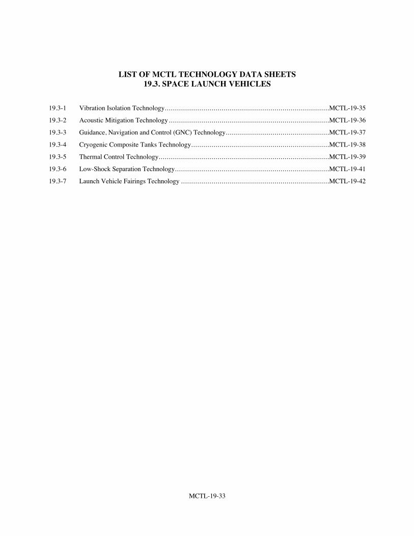
LIST OF MCTL TECHNOLOGY DATA SHEETS19.3. SPACE LAUNCH VEHICLES
19.3-1 Vibration Isolation Technology.................................................................................MCTL-19-35
19.3-2 Acoustic Mitigation Technology...............................................................................MCTL-19-36
19.3-3 Guidance, Navigation and Control (GNC) Technology...................................................MCTL-19-37
19.3-4 Cryogenic Composite Tanks Technology....................................................................MCTL-19-38
19.3-5 Thermal Control Technology....................................................................................MCTL-19-39
19.3-6 Low-Shock Separation Technology............................................................................MCTL-19-41
19.3-7 Launch Vehicle Fairings Technology .........................................................................MCTL-19-42

MCTL-19-35
MCTL DATA SHEET 19.3-1. VIBRATION ISOLATION TECHNOLOGY
Critical TechnologyParameter(s) • All Vibration Isolation Technologies for both axial and lateral axes producing root-
mean-square transmissibility between base and payload of –5 dB (reduction offactor of 3) over the 0–1000 Hz bandwidth.
• A Vibration Isolation System mass < 5% of payload mass.Critical Materials High “E” damping materials; lightweight composite materials for composite fairings;
innovative lightweight, low-cost acoustic damping and active attenuation composites. Hybrid multi-component blankets with tuned acoustic impedance.
Unique Test, Production,Inspection Equipment Systems incorporating active control elements require pre-launch checkout equipment.
Unique Software Systems incorporating active control elements require control algorithm software.Major CommercialApplications Commercial payloads will benefit from this technology since current vibration conditions
cause payloads to be lost or degraded significantly. This allows the launching of lessrugged payload components.
Affordability Issues This technology should provide more affordable launch systems or allow more capabilityfor a given payload weight. The increase in successful launches will significantly reduceoverall program costs in the future.
Export ControlReferences None identified.
BACKGROUND
Spacecraft are typically mounted on launch vehicles with a Payload Attach Fitting (PAF) structure that is verystiff and lightly damped. In most cases, vibration, shock, and loads from the launch vehicle are transmitted directly tothe payload. The requirement to design for this challenging environment adds weight, cost, and risk to the spacecraft.
PAF structures are designed to withstand axial acceleration during boost, which causes static and dynamiccompression loads along the launch vehicle’s long (z) axis (Figure19.3-1). Lateral loads occur due to maneuversinitiated by the vehicles’ guidance system and encounters with wind shear situations. This lateral loading tends toexcite the launch vehicles’ body bending modes and in turn drives lateral displacements of the spacecraft. Also,coupling between axial sinusoidal motion and lateral modes causes significant lateral loads. Launch vehicle vibrationisolation technology would add substantial flexibility and damping to the PAF in both the axial and lateral directionswithout inducing excessive axial, lateral, or rotational displacements that might cause impact of the spacecraft withthe payload fairing or control instability.
Figure 19.3-1. Arrangement of launch vehicle, PAF, and spacecraft, with coordinate systemsdefinition.
MCTL-19-36
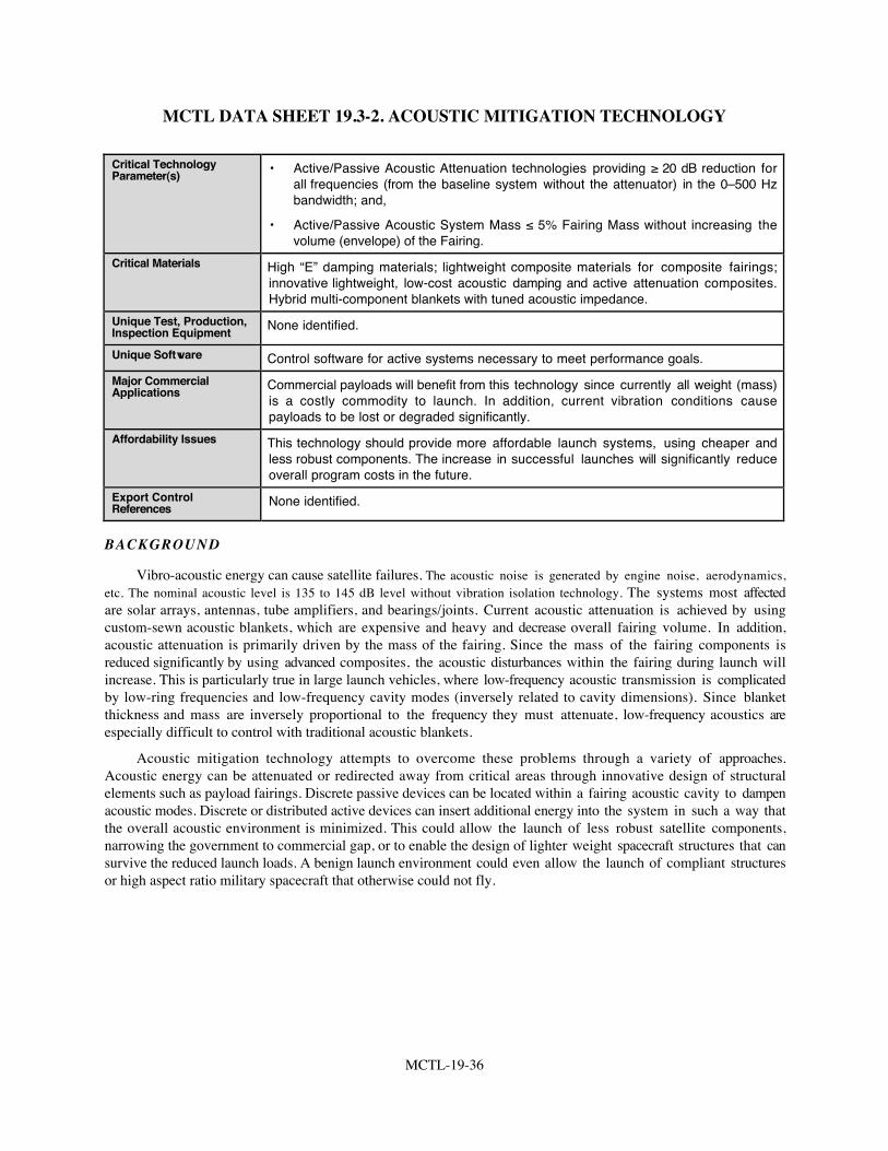
MCTL DATA SHEET 19.3-2. ACOUSTIC MITIGATION TECHNOLOGY
Critical TechnologyParameter(s) • Active/Passive Acoustic Attenuation technologies providing ≥ 20 dB reduction for
all frequencies (from the baseline system without the attenuator) in the 0–500 Hzbandwidth; and,
• Active/Passive Acoustic System Mass ≤ 5% Fairing Mass without increasing thevolume (envelope) of the Fairing.
Critical Materials High “E” damping materials; lightweight composite materials for composite fairings;innovative lightweight, low-cost acoustic damping and active attenuation composites. Hybrid multi-component blankets with tuned acoustic impedance.
Unique Test, Production,Inspection Equipment None identified.
Unique Software Control software for active systems necessary to meet performance goals.Major CommercialApplications Commercial payloads will benefit from this technology since currently all weight (mass)
is a costly commodity to launch. In addition, current vibration conditions causepayloads to be lost or degraded significantly.
Affordability Issues This technology should provide more affordable launch systems, using cheaper andless robust components. The increase in successful launches will significantly reduceoverall program costs in the future.
Export ControlReferences None identified.
BACKGROUND
Vibro-acoustic energy can cause satellite failures. The acoustic noise is generated by engine noise, aerodynamics,etc. The nominal acoustic level is 135 to 145 dB level without vibration isolation technology. The systems most affectedare solar arrays, antennas, tube amplifiers, and bearings/joints. Current acoustic attenuation is achieved by usingcustom-sewn acoustic blankets, which are expensive and heavy and decrease overall fairing volume. In addition,acoustic attenuation is primarily driven by the mass of the fairing. Since the mass of the fairing components isreduced significantly by using advanced composites, the acoustic disturbances within the fairing during launch willincrease. This is particularly true in large launch vehicles, where low-frequency acoustic transmission is complicatedby low-ring frequencies and low-frequency cavity modes (inversely related to cavity dimensions). Since blanketthickness and mass are inversely proportional to the frequency they must attenuate, low-frequency acoustics areespecially difficult to control with traditional acoustic blankets.
Acoustic mitigation technology attempts to overcome these problems through a variety of approaches.Acoustic energy can be attenuated or redirected away from critical areas through innovative design of structuralelements such as payload fairings. Discrete passive devices can be located within a fairing acoustic cavity to dampenacoustic modes. Discrete or distributed active devices can insert additional energy into the system in such a way thatthe overall acoustic environment is minimized. This could allow the launch of less robust satellite components,narrowing the government to commercial gap, or to enable the design of lighter weight spacecraft structures that cansurvive the reduced launch loads. A benign launch environment could even allow the launch of compliant structuresor high aspect ratio military spacecraft that otherwise could not fly.
MCTL-19-37
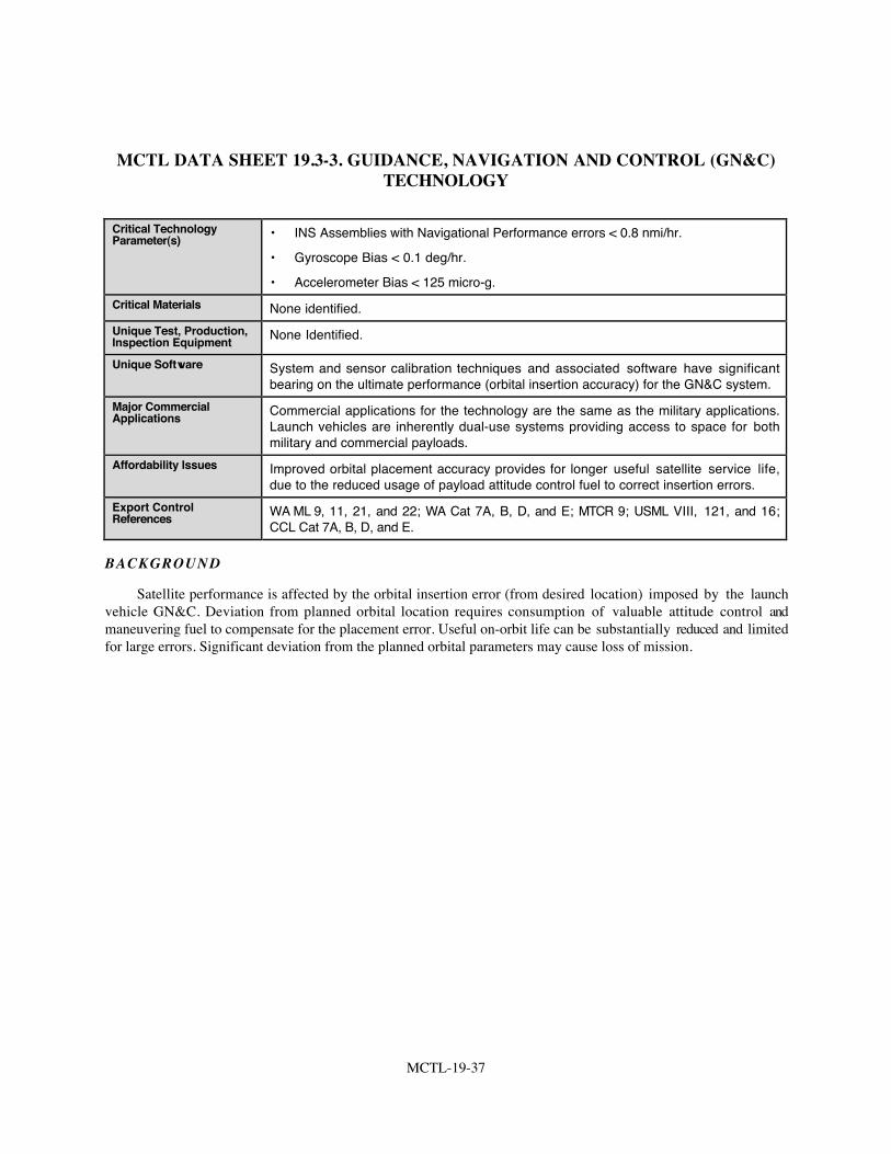
MCTL DATA SHEET 19.3-3. GUIDANCE, NAVIGATION AND CONTROL (GN&C)TECHNOLOGY
Critical TechnologyParameter(s) • INS Assemblies with Navigational Performance errors < 0.8 nmi/hr.
• Gyroscope Bias < 0.1 deg/hr.
• Accelerometer Bias < 125 micro-g.Critical Materials None identified.Unique Test, Production,Inspection Equipment None Identified.
Unique Software System and sensor calibration techniques and associated software have significantbearing on the ultimate performance (orbital insertion accuracy) for the GN&C system.
Major CommercialApplications Commercial applications for the technology are the same as the military applications.
Launch vehicles are inherently dual-use systems providing access to space for bothmilitary and commercial payloads.
Affordability Issues Improved orbital placement accuracy provides for longer useful satellite service life,due to the reduced usage of payload attitude control fuel to correct insertion errors.
Export ControlReferences WA ML 9, 11, 21, and 22; WA Cat 7A, B, D, and E; MTCR 9; USML VIII, 121, and 16;
CCL Cat 7A, B, D, and E.
BACKGROUND
Satellite performance is affected by the orbital insertion error (from desired location) imposed by the launchvehicle GN&C. Deviation from planned orbital location requires consumption of valuable attitude control andmaneuvering fuel to compensate for the placement error. Useful on-orbit life can be substantially reduced and limitedfor large errors. Significant deviation from the planned orbital parameters may cause loss of mission.

MCTL-19-38
MCTL DATA SHEET 19.3-4. CRYOGENIC COMPOSITE TANKS TECHNOLOGY
Critical TechnologyParameter(s) • Composite material able to withstand microcracking due to thermal stresses ≥ 50 K
and pressure of ≥ 800 psi.
• RLV tanks that maintain structural soundness and is qualified through 1000pressurization and depressurization cycles without structural failure.
Critical Materials Resins with low coefficient of thermal expansion. Composite materials that arechemically inert to LOX, LN2, Peroxide, rocket and jet fuels.
Unique Test, Production,Inspection Equipment None identified.
Unique Software None identified.Major CommercialApplications Low cost access to space in addition to prolonged space flight and reduced weight of
non-space vehicles. Low weight structures will greatly reduce deployment costs forboth space and non-space vehicles. Will also allow singe-stage-to-orbit launches.
Affordability Issues With much of the technology described herein, affordability is tied primarily torefinements in associated processes, through standardized production and higherproduction volumes.
Export ControlReferences Controlled as a material in WA Cat 1A, 1C, and 9A; CCL Cat 1A, 1C and 9A.
BACKGROUND
Composite cryogenic pressure vessels are a lighter and cheaper alternative to conventional metal tanks. Theweight savings of up to 60 percent have a significant effect on the cost of launching a vehicle into space. These costsavings are applicable to all space vehicles as well as non-space vehicles. However, implementation of compositetanks in a cryogenic environment has been limited due to microcracking of the resin material of the tank. Thesemicrocracks propagate to the point of tank leakage or ultimate failure.
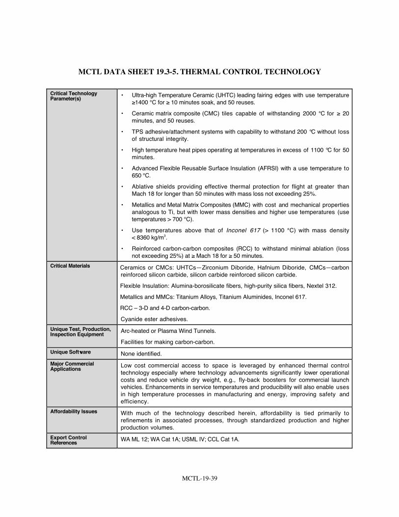
MCTL-19-39
MCTL DATA SHEET 19.3-5. THERMAL CONTROL TECHNOLOGY
Critical TechnologyParameter(s) • Ultra-high Temperature Ceramic (UHTC) leading fairing edges with use temperature
≥1400 °C for ≥ 10 minutes soak, and 50 reuses.
• Ceramic matrix composite (CMC) tiles capable of withstanding 2000 °C for ≥ 20minutes, and 50 reuses.
• TPS adhesive/attachment systems with capability to withstand 200 °C without lossof structural integrity.
• High temperature heat pipes operating at temperatures in excess of 1100 °C for 50minutes.
• Advanced Flexible Reusable Surface Insulation (AFRSI) with a use temperature to650 °C.
• Ablative shields providing effective thermal protection for flight at greater thanMach 18 for longer than 50 minutes with mass loss not exceeding 25%.
• Metallics and Metal Matrix Composites (MMC) with cost and mechanical propertiesanalogous to Ti, but with lower mass densities and higher use temperatures (usetemperatures > 700 °C).
• Use temperatures above that of Inconel 617 (> 1100 °C) with mass density< 8360 kg/m3.
• Reinforced carbon-carbon composites (RCC) to withstand minimal ablation (lossnot exceeding 25%) at ≥ Mach 18 for ≥ 50 minutes.
Critical Materials Ceramics or CMCs: UHTCs—Zirconium Diboride, Hafnium Diboride, CMCs—carbonreinforced silicon carbide, silicon carbide reinforced silicon carbide.
Flexible Insulation: Alumina-borosilicate fibers, high-purity silica fibers, Nextel 312.
Metallics and MMCs: Titanium Alloys, Titanium Aluminides, Inconel 617.
RCC – 3-D and 4-D carbon-carbon.
Cyanide ester adhesives.Unique Test, Production,Inspection Equipment Arc-heated or Plasma Wind Tunnels.
Facilities for making carbon-carbon.Unique Software None identified.Major CommercialApplications Low cost commercial access to space is leveraged by enhanced thermal control
technology especially where technology advancements significantly lower operationalcosts and reduce vehicle dry weight, e.g., fly-back boosters for commercial launchvehicles. Enhancements in service temperatures and producibility will also enable usesin high temperature processes in manufacturing and energy, improving safety andefficiency.
Affordability Issues With much of the technology described herein, affordability is tied primarily torefinements in associated processes, through standardized production and higherproduction volumes.
Export ControlReferences WA ML 12; WA Cat 1A; USML IV; CCL Cat 1A.

MCTL-19-40
BACKGROUND
The purpose of the thermal control system is to protect the launch vehicle from heat damage during launch, inspace, and during reentry, if necessary. It is composed of several subsystems and technologies designed to meet theunique requirements for the launch system. The thermal control system will vary greatly from one launch vehiclesystem to the next due the multiplicity of vehicle architectures (expendable, reusable, SSTO, multi-stage), missions(light/heavy lift, manned, polar, etc.), and design heritage among other things. Emerging military launch systemrequirements are emphasizing rapid response, reduced operational costs, and increased reliability.

MCTL-19-41
MCTL DATA SHEET 19.3-6. LOW-SHOCK SEPARATION TECHNOLOGY
Critical TechnologyParameter(s) • Release Shock < 10 g, without increase in rotational forces at release over that of
conventional systems.
Note: Typical rotational forces without low shock technology are in the range of 0.1to 0.2 deg/s.
Critical Materials Several critical materials can be associated with low-shock separation systems,including paraffin and shape memory alloys (SMA’s), but these materials are criticalonly to specific approaches rather than the technology as a whole.
Unique Test, Production,Inspection Equipment None identified.
Unique Software None identified.Major CommercialApplications The same as the military applications, namely low shock mechanical systems for
separation of spacecraft, mechanical actuators, mechanical release devices, etc.Affordability Issues Not an issue.Export ControlReferences None identified.
BACKGROUND
A payload delivered to orbit from a launch vehicle must typically be separated from the vehicle payloadattachment fitting prior to operation. Typical pyrotechnic separation systems generate shock loads between 5000 and10,000 gs. This shock loading has the potential to damage the payload, requiring more massive and robust designs tosurvive these loads. A reduction in separation shock loads can translate into reduced mass designs or increased riskmargin. If a low shock system exhibits a rotational force in excess of 0.2 deg/s (or above the nominal value of theconventional release system) then it is not of military value and is not militarily critical.
MCTL-19-42
MCTL DATA SHEET 19.3-7. LAUNCH VEHICLE FAIRINGS TECHNOLOGY
Critical TechnologyParameter(s) Launch vehicle fairings capable of supporting maximum payload dimensions of
10 meters in diameter and able to withstand aerodynamic pressure loads exceeding3000 psi.
Critical Materials None identified.Unique Test, Production,Inspection Equipment Out-of-autoclave curing techniques can increase manufacturability. Large out of
autoclave processes have been identified from COTS processes already in the openliterature.
Unique Software Control algorithms to maintain launch vehicle stability, reduce flutter inputs, andminimize fuel consumption to orbit are critical to successful launch of high aspecthammerhead fairings and non-circular cross-sections.
Major CommercialApplications Commercial payloads will benefit from this technology to the extent that very large
payload volumes can be used without exceeding mass limits.Affordability Issues None identified.Export ControlReferences WA Cat 9A; CCL Cat 9A.
BACKGROUND
The greatest difficulty in placing a large fairing, particularly one that is not entirely symmetric to a practicalorbit would be in providing measures during launch to insure stability, minimize buffeting, and reduce fuelrequirements as needed to attain the desired orbit.

MCTL-19-43
SECTION 19.4–SPACE OPTICS
Highlights
• Extremely lightweight component and structure technology for space optics, vital to our future spacerequirements, provides lightweight, high stiffness precision monolithic structures with an areal density* of< 15 kg/m2.
• Significantly improved optical “Composite” components having a coefficient of linear thermal expansion< 5 × 10⁻⁶ in all coordinate axes and an areal density* of < 20 kg/m2 are scheduled for the military spaceprogram.
• Segment mirrors or assemblies of mirrors designed to be assembled in space with optical aperture segments> 0.5 m or full apertures > 3.0 m.
• Nanometer optical tolerances of space platforms with large deployable mirrors (10s of meters in diameter)will provide near diffraction limited optical surveillance and significantly improve space surveillanceresolution and image quality.
• Significant improvements in Deformable Mirrors (DMs) for space applications, from improved frequencyresponse to larger throw distances and less hysteresis.
• Space Optics Tip/Tilt mirrors (2-axis controls) with bandwidths > 500 Hz have significantly improvedcapabilities for Space Relay Optics.
• New high frequency, low hysteresis actuators are greatly improving the capability of active optics.
• Liquid crystals have often been too slow for adaptive optics application, but with recent developments, thathas been overcome by switching speeds > 250 µsec.
• A new and novel method of electrically addressing liquid crystals for adaptive optics is called modaladdressing and the improvements are very significant.
• Optical component and coating protection from atomic oxygen is a key new development.
• Major advances in optical coating material technologies improve the hardness and environmentalsurvivability of military optics hardware.
• Vibration-isolation and damping systems in conjunction with precision fixtures of flexible space structurescan now achieve better than 30 nm mirror position stability.
• Significantly improved Micro-Opto-Electro-Mechanical Systems (MOEMS) are now replacing electroniccomponents where optical switching and high bandwidth is required.
• Major improvements in speed and throughput while still reducing the cost of micro-optics has occurred,permitting MOEMS to begin replacing electronic on-chip components.
OVERVIEW
Space Optics includes all space unique optics technologies. If an optics technology for terrestrial applications ismodified for space use or if it is specially designed for a space application, it will be included in this section.
* Areal Density is a two-dimensional term in optics representing the mass of the optical mirror per unit area of
the optical surface.

MCTL-19-44
The specific optics technologies outlined in this section include large optical mirrors for space surveillance andas relay optics. The very large mirror structures planned for some military applications require new innovativeapproaches to what looks like “erector set” optics where segments of the large pieces of the optic are erected orpositioned at appropriate locations within the aperture of the optic. This means the optical components must befolded for launch and then erected in space by remote or in situ placement of components via robotics.
Deployable optics are required for the many surveillance applications currently being utilized. Commercial, aswell as military, surveillance applications are demanding higher resolution and larger light gathering power.
Space applications require large, extremely lightweight mirrors that have diameters in the 4-to 100-m range andF numbers in the 1.5 to 2.5 range. A fast focal ratio is needed for compact, lightweight space optics that have thelight-gathering power and resolution required to meet current military requirements, which include fractionalwavelength tolerances. Thin glass shells attached to actuators on a lightweight rigid support structure constitute thecurrent developing technology. Alternate technologies are also being addressed and include thin plastic, mylar, and/ormetal-foil-stretched membranes. Using many smaller flat surfaces to form a primary optic configuration may be anacceptable technology to meet this requirement. The technology will require hundreds to thousands of square-metersurface for some applications. All these large-optics technologies are currently being investigated at a lowdevelopmental level.
Many space optics require special preparations including specially designed optical coatings to avoid orminimize the effects of the space environment. Protection coatings are required on some optical components that arenot themselves optical surfaces but still require special preparation for space use. Protection from atomic oxygen andother harsh environmental contaminants is required of all space optics. Space surveillance optics for some specializedapplications require stringent temperature control of the optics. Active or passive cooling becomes a necessity insuch cases. Cooled optics include those with passive cooling methods using phase change materials and radiativetransfer techniques. The cooled optics technologies are covered in the terrestrial applications optic, Section 11-3 ofthe MCTL.
Deformable Mirrors (DMs) are sometimes identified by different names including “Adaptive Optics” or “ActiveOptics.” Deformable mirrors include mirrors for which the surface can be statically or dynamically repositioned tooptimize the beam’s wavefront. Some of these mirrors are currently being developed for space applications such asspace surveillance for GEO laser communication links. Adaptive optics, when used in space, have some additionalrequirement such as the hermetically sealed actuator assemblies to avoid out-gassing and reduction by atomic oxygen.In addition, one needs special lubricants to maintain movement on mount points and special fixturing to withstandthe high “g” loads of a launch. In addition to the actuators supporting the mirror surface, special structural supportactuators are also needed to maintain alignment of structural components as in the deployable optics that unfold intothe desired optical format.
The hardware one needs for space optics involves many autonomous and robotic structures including remotepositioning to sub-micron accuracy. The opto-mechanical controls required for some space optics involve techniquesand technologies, which are quite different from terrestrial applications.
Space applications for MOEMs are becoming the “fast-track” approach to optical applications such as opticalswitching where electronic connections and switches are a hazard or arrays of micro mirrors actuated independently forcommunication applications. Space applications of MOEMS technology are now under development for spaceapplications since MOEMS represent reliable, durable, light-weight replacements for many space electroniccomponents, especially where static electricity is a common problem and the need for mitigating EMI is highlydesired.
Many of the space technologies listed in this section have been developed in concert with or in a cooperativedevelopment arrangement with our allies. This area of research and development remains a window of opportunity forfuture space related endeavors. Many related technologies, which are common to both space and terrestrialapplications, are covered in the Lasers, Optics and Imaging Technology Section of the MCTL.

MCTL-19-45
BACKGROUND
The need for larger aperture optics in space is driven by many applications and goals. The U.S. Government’sspace program at NASA requires space telescopes with greater resolution and light gathering power in an effort tosearch out other earth-like planets in the galaxy and to continue the extended study the universe. Near-term plans callfor telescopes with 9 to 20 m apertures. More ambitious plans are calling for 100+ meter diameter systems. Alldeep-space imaging missions could benefit tremendously from such systems.
Additionally, the military needs telescopes that point toward earth rather than away from it. The Militaryrequires large aperture surveillance optics to monitor global areas of interest. An 8+ m optical surveillance systemcould, in principle, provide militarily significant imaging from geosynchronous orbit, allowing it to observe aregion of the world 24 hours a day, seven days a week, eliminating the need to wait for revisit times. Such a systemcould provide continuous coverage of a battlefield or sensitive area, a capability of obvious military and politicalsignificance. Of special interest to the military is the fact that any future space-based laser systems will require largeapertures.
Therefore, large, monolithic uncooled optics are required for many space applications, which include mirrors forboth military and commercial surveillance, reconnaissance, acquisition, pointing, tracking, and communications.These optics require high-reflectivity coatings, antireflective or partially transmissive coatings for selectivewavelengths, and/or coatings with holographic elements. More advanced uncooled optics, particularly desirable formilitary space applications, include advanced transmissive capabilities of single-crystal silicon and silicon-carbideoptics. These technologies use lightweight, inexpensive components to achieve the same capability that wasavailable only with much more expensive and heavier components.
Size and weight are major considerations in any space launch. Optical elements are currently limited in size byspace booster payload fairings. Optics, larger than those that can be boosted into space by such launch-vehiclelimitations, must be assembled in space (either from separate pieces or by unfolding elements), or the opticalassemblies must be bolted together in space. “In-space construction” technologies remain critical, particularly forapplications that require exceptionally large, fragile membrane or very lightweight optics (too large and/or too fragilefor launch stresses). Technologies for unfolding or assembling large optics and for obtaining and maintaining propershape and finish in the process also remain critical but are now under development. In addition, software algorithmsthat determine and then compensate for deformations or that purposely deform elements in space optics are critical forobtaining and maintaining high resolution for space optics.
Deformable Optics are also referred to as Smart Optics, Adaptive Optics or Active Optics. They include anyoptical component whose optical surface can be controlled or adjusted dynamically to enhance the optical systemperformance. Deformable mirrors are required in some applications for improving space surveillance opticsresolution. It should be noted that (quasi-static) errors in optics such as telescope optics are usually controlled by alow bandwidth optical system, usually referred to as “Active Optics.” The (high dynamic) controlled optics typicallyrequired for correcting atmospheric turbulence inside and above the telescope are usually referred to as “AdaptiveOptics” and in the case of a closed loop system they are sometimes referred to as “Smart Optics.”
The technique of deforming optical surfaces has succeeded in producing even sharper and clearer images than theHubble Space telescope from terrestrial telescopes. As the use of optics in space has increased and size and weighthave become more important, changes have become necessary in the design, manufacturing, and process controls ofthese new technologies to provide affordable, lightweight, rugged, and highly reliable systems. Many new MEMSand MOEMS applications incorporating lasers and optics have spawned numerous designs for reducing the weightand size of space electronics and optical components such as in-line adaptive optics.
MOEMS and optical micromirrors technology has been extended to optical communication where fastswitching of laser light is enabled with micromirrors, microshutters, or microbubbles. The communication industrywill soon see MOEMS devices as tunable lasers (VCSELs), resonators, interferometers, and multiplexers. The sametechnology that is embodied in these components is used by the military for adaptive optics and switchingapplications.

MCTL-19-46
The use by commercial firms of space optics technologies is important in the overall affordability of the spacecomponent or system for both the commercial and the military sectors. Many satellite payloads are now planning onusing micro-optic technologies in the form of MEMS and MOEMS for space platform components.

MCTL-19-47
LIST OF MCTL TECHNOLOGY DATA SHEETS19.4. SPACE OPTICS
19.4-1 Deployable Monolithic and Segmented Optics .............................................................MCTL-19-49
19.4-2 Deformable Mirrors/Adaptive Optics and Support Mechanisms .......................................MCTL-19-52
19.4-3 Micro-Opto-Electro-Mechanical Systems (MOEMS).....................................................MCTL-19-54

MCTL-19-49
MCTL DATA SHEET 19.4-1. DEPLOYABLE MONOLITHIC AND SEGMENTEDOPTICS
Critical TechnologyParameter(s) • Lightweight, high stiffness precision monolithic structures with:
a. an areal density of < 15 kg/m2, andb. a fundamental frequency > 1.5 kHz.
• Optical “Composite” Components having:a. a coefficient of linear thermal expansion < 5 x 10⁻⁶ in any coordinate axis,b. an areal density of < 20 kg/m2, andc. a fundamental frequency > 1.5 kHz
• Segment mirrors or mirror assemblies designed to be assembled in space with:a. optical segments (for segmented mirrors) > 0.5 m, orb. full aperture optics > 3 m.
• Technology for measuring Zero-g figure and tolerances in 1-g conditions (terrestrialsetting) for lightweighted space optics structures < 30 kg/m2.
• Rapid optical fabrication technology for large (> 10 m2) monolithic or segmentedprimary mirrors.
• Hinges, latches and related mechanisms capable of providing < 10 nm mirror surfacefigure stability.
• Optical structure isolation systems with:a. damping coefficients of > 30 dB, andb. for frequencies between 1 Hz and 105 Hz.
• Vibration-isolation and damping systems for flexible structures to achieve < 30 nmmirror position stability.
• Visible and infrared wavelength high reflectance, low stress, durable, opticalcoatings which can survive the space environment of atomic oxygen for > 5 years.
• Optical Component coating protection technology for atomic oxygen.• All space-based high energy laser (HEL) optics.
Critical Materials • Corning ULE, Schott Zerodur, silicon carbide, beryllium, graphite (and other)composites, ceramic bearing components, adhesives used in construction of thesematerials and the assembly of components/structures
Unique Test, Production,Inspection Equipment • Production: Large, high temperature furnaces for the above ultra-high purity
materials, including very high pressure autoclaves for beryllium, large CNCmachines, machine tools for precision bearing production, large thermal-vacuumchambers in clean rooms and associated coating application instrumentation.
• Testing: large, high precision coordinate measuring machines, high speed visiblewavelength and infrared wavelength interferometers, precision lenses and diffractiveoptical elements for aspheric primary mirror null correctors, large, precision airbearings, high density CCD focal planes and associated electronics, large thermal-vacuum space-simulation chambers and gravity-offload devices.
• Inspection: Technology for measuring 0-g figure and tolerances in 1-g conditions(terrestrial setting) for lightweighted structures < 30 kg/m2.
MCTL-19-50
Unique Software • Software developed for the modeling and analysis of figure-controlled mirrors,wavefront sensing software; possibly software tools developed specifically for theanalysis of lightweight structures.
Major CommercialApplications • Earth resources instruments and satellites use similar technology but at small or
modest size. Ground-based telescopes use similar materials but with much moremassive designs. Many new space surveillance applications are emerging daily sothe growth in the commercial area will expand significantly.
Affordability Issues • Lightweight optics tend to be significantly more costly than ground-based optics dueto the need for new technology investment, material purity and certification, and theincreased need for design, analysis, and verification for space programs.
• The dominant term in the affordability equation is access to space. Since size andweight determine cost to orbit, major goals for the large optics community includesignificant reduction of areal densities, efficient packaging, and precisiondeployment technologies. Lowering payload weight and efficiently stowing largeoptics for on orbit unfolding and deployment can reduce launch costs by an order ofmagnitude.
• Commercial business practices provide the means to dramatically reduce the costsof sophisticated government satellites. However, in the area of large space optics,government is the primary user, exclusively responsible for supporting advances intechnology and implementing cost saving measures.
• Since the global investment in space is overwhelmingly dominated by the commercialsector, beneficial partnerships should expand beyond government interests. Toparticipate in the sky rocketing commercial investments in space, the opticscommunity needs to develop a broader perspective of future technologyapplications. Distributed spacecraft technology and automated operations areexamples of near term industrial partnership opportunities.
Export ControlReferences WA ML 15 and 19; WA Cat 6A, 6C; CCL Cat 6B; USML XII.
BACKGROUND
To have timely and precise space surveillance, orbital mechanics requires that a space telescope (capable ofviewing a given location on the earth for increasingly long periods of time) orbit the earth at increasingly higheraltitudes. On the other hand, optical physics requires that to maintain constant angular resolution, higher orbitingtelescopes must have proportionally larger primary mirror diameters. The limited available suite of launch vehiclefairing diameters constrains large aperture telescopes from being placed on-orbit without first folding them for launchand deploying or assembling the components once on-orbit or building them in space as one would an erector setconstruction. The cost of launch vehicles capable of lifting very large masses to orbit is high, leading to a desire toreduce the mass of the telescopes, both optics and structures, thereby allowing the use of less costly launchers.
The need to reduce mass leads to thinner, more flexible mirrors but without any relaxation in the surface figuretolerances of those mirrors. The large mirrors must be fabricated and tested economically, leading to a drive forinnovation of otherwise well-established optical fabrication techniques. Furthermore, the segmentation of theprimary mirror adds a new dimension to fabrication tolerancing to ensure that the various segments are capable offunctioning as a single, large optic on-orbit.
The increased flexibility of the mirrors results in significantly more deformation of the mirror surface due togravity, making ground verification in 1-g for a 0-g performance design increasingly challenging. Furthermore, thedifficulty of verification increases the attractiveness of being able to adjust the mirror shape on-orbit, leading to anincreased need for space-rated figure-control actuators. An increased reliance on adjustability drives the need forincreasingly-capable wavefront sensing subsystems that can rapidly measure the multiple degrees of freedom required.In an effort to reduce system complexity, designers turn to more exotic, higher-stiffness materials for large,lightweight mirrors and structures.
MCTL-19-51
Although the reasons are somewhat different, future planned astronomy and commercial surveillance missionshave many similar technology drivers. Unfilled apertures are suitable for several space science missions.Interferometers, as opposed to direct-imaging systems, will require widely-spaced yet potentially large telescopes on along, dimensionally-stable, structure.
The need for larger aperture optics in space is driven by multiple and very different goals depending on whetherthe government or commercial interests are considered. The U.S. Government space program (NASA) is planningspace telescopes with greater resolution in an effort to search out other earth-like planets in the galaxy. Near-termplans call for telescopes with 9 to 20-m apertures. More ambitious plans are calling for 100+ m systems. All deep-space imaging missions would benefit tremendously from such systems.
Additionally, the Air Force needs telescopes that point toward earth rather than away from it. An 8+ m opticalsurveillance system could, in principle, image from geosynchronous orbit, allowing it to observe a region of theworld 24 hours a day, seven days a week, eliminating the need to wait for revisit times. Such a system could providecontinuous coverage of a battlefield or sensitive area, a capability of obvious military and political significance. Ofadditional interest to the military, any future space-based laser systems will require large apertures to be militarilysignificant.
In contrast, commercial interests are centered more on mapping, climatologic, ozone layers, and cropevaluation. Although different deployable systems may take a variety of forms, technical challenges for all thesesystems are very similar. The most difficult problem to solve is that of deployment accuracy. Optical surfaces mustbe shaped to a tolerance that is just a fraction of the wavelength of the light being collected. In practice, thiscondition requires that optical surfaces have a tolerance of about ten nanometers, or ten billionths of a meter, astaggeringly small number.
Significant differences in performance requirements and operating environments exist between NASA and DoDspace systems. The NASA Next Generation Space Telescope (NOST), now called the James Webb Space Telescope,will use scene based wavefront sensing; whereas, aberrations caused by high-energy laser beams are corrected usingtarget independent wavefront sensing. NOST will operate in a sun-shielded cryogenic thermal environment. DoDsystems operate in a very dynamic thermal environment and may be in the proximity of a high-energy laser.Similarly, operating timelines and demands on the telescope structures will differ considerably.
Although the missions and operational requirements are obviously different, technology goals for large,lightweight deployable space optics have many commonalties. Since the most pressing needs are in the area offabrication and testing of large lightweight segments, the Advanced Minor System Demonstrator (AMSD) programwas established. The common objectives in Hubble units are a 10× increase in area, 15–20× reduction in arealdensity, 10× reduction in cost, and greater than 10× increase in production rate. Contracts with industry are in placewith a dual management arrangement to ensure satisfactory product delivery for all partners.
Lightweight future system concepts include collaborating satellite constellations, integrated sensor-craft, sparsearrays, and inflatable, deployable membranes or gossamer optics. When combined with inflatable or other novelstructures, weight and packaging volume could be reduced to a fraction of today’s figures. A number of excitingprograms have shown potential and are developing the technology to meet the technical challenges of space opticssystems.
MCTL-19-52
MCTL DATA SHEET 19.4-2. DEFORMABLE MIRRORS/ADAPTIVE OPTICS ANDSUPPORT MECHANISMS
Critical TechnologyParameter(s)
The militarily critical parameters listed below are for optical space components, whichdynamically or statically moves the surface of an optic. This list includes componentsspecially designed for space applications which can correct laser beam wavefronts suchas non-linear optical components or liquid crystal modulators (in conjunction with AO or asstand alone components) as follows:1. Actuators
a. Working at a frequency > 200 Hz but ≤ 300 Hz,b. with a positioning and repositioning accuracy < 30 nm,c. precision < 20 nm, andd. a full stroke > 3 µm
2. Actuatorsa. At a frequency > 300 Hz,b. with a positioning and repositioning accuracy, < 30 nm,c. precision of < 50 nm, andd. a full stroke > 3 µm.
3. Actuatorsa. With large stroke range > 5 mm, andb. high resolution positioning accuracy (< 30 nm).
4. Deformable optical mirror surfacesa. With < 30 nm deviation from prescribed figure in dynamic or static configurations,
andb. optical diameter or major axis of > 25 mm.
5. High-precision mechanisms for optical system deployment in space with positioning of:a. < 1 × 10⁻⁵ meter accuracy, andb. < 1 part in 106 precision.
6. Advanced control system and actuator designs for optical-precision structural controlswith controlled movement of < 10-9 meters/meter of separation between opticalelements.
7. Optical beam steering optical components with:a. Diameters (or major axis) > 10 cm,b. flatness < 50 nm., andc. a control bandwidth > 200 Hz.
8. Non-linear Optics components, such as liquid crystals and other phase control materialcomponents, specially designed for space optics applications and use as follows:a. Nonlinear phased arrays with > 250 µsec switching speed,b. wide-angle beam steering > + 45° field of regard, andc. high-speed liquid crystals > 104 Hz.

MCTL-19-53
Critical Materials None identified.[None of these entries are materials. If there are materials, then they should be listed.]
Unique Test, Production,Inspection Equipment
• Production: None identified.• Testing: Improved nulling techniques for the control surface.• Inspection: None identified.
Unique Software None identified.Major CommercialApplications
Ground-based Optical Telescopes: developmental items such as artificial eyes, high-speed telecommunication links, ophthalmic instrumentation as well as the well establishedapplications such as semiconductor lithography, and industrial laser system optimizationcomponents. Other possible application areas include commercial laser beam correction, laser beamforming, laser materials processing, scanning optical systems, optical probes andconfocal microscopes, coupling of micro-optics, and several areas of optical imaging,including imaging of the retina in vivo.
Affordability Issues Lower cost will result with further development work, which should improve performance,decrease complexity and increase the bandwidth substantially. This will reduce the cost forthe next generation of giant telescopes.
Export ControlReferences WA Cat 6A and Cat 1E; WA ML 15 and 19; CCL Cat 6A and 6B; USML XII.
BACKGROUND
A significant technological development in the field of laser optics is deformable or adaptive optics. Developedto combat fluctuations in air temperature and the consequent atmospheric turbulence that weakens and scatters thelaser’s beam, adaptive optics relies on a deformable mirror, sometimes called a “rubber mirror,” to compensate fortilt and phase distortions in the atmosphere. The mirror typically has hundreds of actuators that change hundreds tothousands of times per second when driven by a wavefront sensor, enabling the mirror to modify the laser beam sothat it can travel further through turbulent air.
Today, deformable mirrors for astronomy are usually made of a very thin sheet of glass or low thermalexpansion material with a diameter of several inches to meters in size. Attached to the back of the glass are variouskinds of “actuator” devices which expand or contract in length in response to a voltage signal, bending the thin sheetof glass locally to the intended wavefront correction. A deformable mirror is able to correct a distorted beam of lightfrom a star, by straightening out the incoming wavefront.
For astronomy and for military applications, wavefront sensors must measure turbulence hundreds to thousandsof times a second. The detector doing this work is typically a fast charge coupled device (CCD), similar to those usedat slower speeds in today’s video cameras, or else a set of avalanche photodiodes (APDs) mapping out the centroid ofbeamlets in a Shack-Hartmann set up.

MCTL-19-54
MCTL DATA SHEET 19.4-3. MICRO-OPTO-ELECTRO-MECHANICAL SYSTEMS(MOEMS)
Critical TechnologyParameter(s)
• MOEMS with a frequency > 500 Hz, and• MOEMS with:
1. ≥ 100 actuator mirrors;2. ≥ ± 1 micrometer displacement throw; and3. > 95% areal density (fill factor).
Critical Materials None identified.Unique Test, Production,Inspection Equipment • Production:
1. Very stringent tolerances are required for micro-opto devices and componentsfor space applications; and
2. Micro lenses and micro-beam splitters require position tolerances of < 1 mrad.• Testing: None identified.• Inspection: None identified.
Unique Software None identified.Major CommercialApplications
MOEMS are used in a wide range of applications for medical, biotechnology, automotive,wireless telecommunications, fiber optic telecommunications, information peripherals,environmental monitoring, and industrial automation, including:• Sensing, sorting and monitoring of solids, liquids and gases based on spectroscopy,
e.g., for environmental monitoring, waste management or food quality control;• Development of miniature medical sensors and recorders for permanent implantation
in patients;• Mass data storage devices;• Systems for storing densities of terabytes per square centimeter;• Integrated micro-opto-mechanical components for identify-friend-or-foe systems;• Displays and fiber-optic switches/modulators;• Active, conformable surfaces for distributed aerodynamic control of aircraft;• Adaptive optics; and• Gyro applications and motion sensing and correction.
Affordability Issues The lower cost comes about since MOEMS can be fabricated with current IC technologyon Silicon substrates. Mass production can achieve tremendous cost savings and thesmall size provides utility in new and diverse applications.
Export ControlReferences
None identified.
BACKGROUND
Micro-opto-electro-mechanical systems (or as some say “micro-optic- electro-mechanical systems”) MOEMSare the optical-electronic devices which are fabricated on silicon chips using silicon processor fabrication technology.These novel optical elements are characterized by high efficiency, design flexibility, lightweight, small size andruggedness. Furthermore, they can be replicated at low cost in mass production. They use the same processingtechnologies required for the IC semiconductor industry.
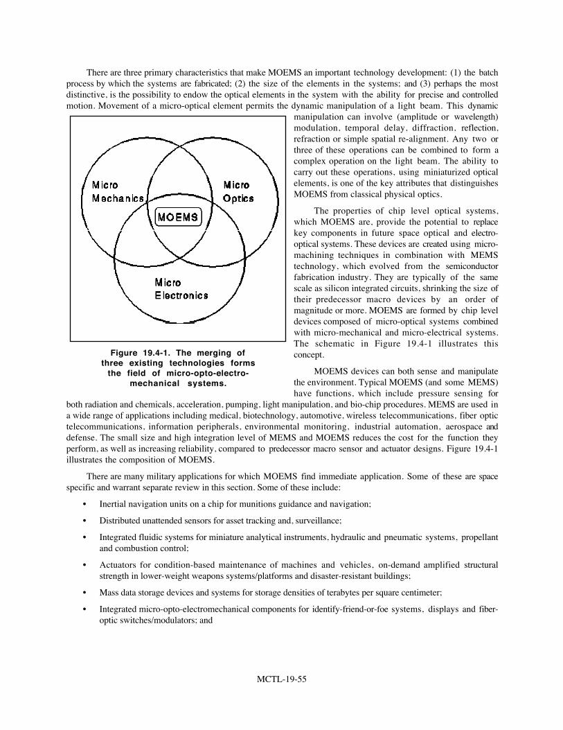
MCTL-19-55
There are three primary characteristics that make MOEMS an important technology development: (1) the batchprocess by which the systems are fabricated; (2) the size of the elements in the systems; and (3) perhaps the mostdistinctive, is the possibility to endow the optical elements in the system with the ability for precise and controlledmotion. Movement of a micro-optical element permits the dynamic manipulation of a light beam. This dynamic
manipulation can involve (amplitude or wavelength)modulation, temporal delay, diffraction, reflection,refraction or simple spatial re-alignment. Any two orthree of these operations can be combined to form acomplex operation on the light beam. The ability tocarry out these operations, using miniaturized opticalelements, is one of the key attributes that distinguishesMOEMS from classical physical optics.
The properties of chip level optical systems,which MOEMS are, provide the potential to replacekey components in future space optical and electro-optical systems. These devices are created using micro-machining techniques in combination with MEMStechnology, which evolved from the semiconductorfabrication industry. They are typically of the samescale as silicon integrated circuits, shrinking the size oftheir predecessor macro devices by an order ofmagnitude or more. MOEMS are formed by chip leveldevices composed of micro-optical systems combinedwith micro-mechanical and micro-electrical systems.The schematic in Figure 19.4-1 illustrates thisconcept.
MOEMS devices can both sense and manipulatethe environment. Typical MOEMS (and some MEMS)have functions, which include pressure sensing for
both radiation and chemicals, acceleration, pumping, light manipulation, and bio-chip procedures. MEMS are used ina wide range of applications including medical, biotechnology, automotive, wireless telecommunications, fiber optictelecommunications, information peripherals, environmental monitoring, industrial automation, aerospace anddefense. The small size and high integration level of MEMS and MOEMS reduces the cost for the function theyperform, as well as increasing reliability, compared to predecessor macro sensor and actuator designs. Figure 19.4-1illustrates the composition of MOEMS.
There are many military applications for which MOEMS find immediate application. Some of these are spacespecific and warrant separate review in this section. Some of these include:
• Inertial navigation units on a chip for munitions guidance and navigation;
• Distributed unattended sensors for asset tracking and, surveillance;
• Integrated fluidic systems for miniature analytical instruments, hydraulic and pneumatic systems, propellantand combustion control;
• Actuators for condition-based maintenance of machines and vehicles, on-demand amplified structuralstrength in lower-weight weapons systems/platforms and disaster-resistant buildings;
• Mass data storage devices and systems for storage densities of terabytes per square centimeter;
• Integrated micro-opto-electromechanical components for identify-friend-or-foe systems, displays and fiber-optic switches/modulators; and
Figure 19.4-1. The merging ofthree existing technologies forms
the field of micro-opto-electro-mechanical systems.
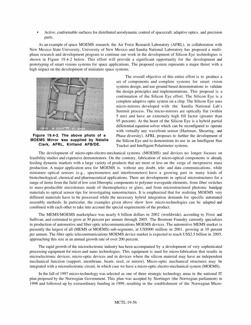
MCTL-19-56
• Active, conformable surfaces for distributed aerodynamic control of spacecraft, adaptive optics, and precisionparts.
As an example of space MOEMS research, the Air Force Research Laboratory (AFRL), in collaboration withNew Mexico State University, University of New Mexico and Sandia National Laboratory has proposed a multi-phase research and development program to continue our work in the development of Silicon Eye technologies isshown in Figure 19.4-2 below. This effort will provide a significant opportunity for the development andprototyping of smart visions systems for space applications. The proposed system represents a major thrust with ahigh impact on the development of miniature space systems.
The overall objective of this entire effort is to produce aset of components and complete systems for smart visionsystems design, and use ground based demonstrations to validatethe design principles and implementations. This proposal is acontinuation of the Silicon Eye effort. The Silicon Eye is acomplete adaptive optic system on a chip. The Silicon Eye usesmicro-mirrors developed with the Sandia National Lab’sSummit process. The micro-mirrors are optically flat (within5 nm) and have an extremely high fill factor (greater than95 percent). At the heart of the Silicon Eye is a hybrid partialdifferential equation solver which can be reconfigured to operatewith virtually any wavefront sensor (Hartman, Shearing, andPhase diversity). AFRL proposes to further the development ofthe Silicon Eye and to demonstrate its use in an Intelligent StarTracker and Intelligent Polarimeter systems.
The development of micro-opto-electro-mechanical systems (MOEMS) and devices no longer focuses onfeasibility studies and expensive demonstrators. On the contrary, fabrication of micro-optical components is alreadyfeeding dynamic markets with a large variety of products that are more or less on the verge of inexpensive massproduction. A major application area for MOEMS is, without any doubt, tele- and data communications, whileminiature optical sensors (e.g., spectrometers and interferometers) have a growing part in many kinds ofbiotechnological, chemical and pharmaceutical applications. There are developments in optical microstructures for arange of items from the field of low cost fiberoptic components to polymer waveguide elements, from fiber switchesto mass-producible microlenses made of thermoplastics or glass, and from microstructured photonic bandgapmaterials to optical sensor tips for investigating nanostructures. It is emphasized that for realizing MOEMS verydifferent materials have to be processed while the necessary hybrid integration demands for specific automatedassembly methods. In particular, the examples given above show how micro-technologies can be adapted andcombined with each other to take into account the special requirements of the product.
The MEMS/MOEMS marketplace was nearly 6 billion dollars in 2002 (worldwide), according to Frost andSullivan, and estimated to grow at 30 percent per annum through 2005. The Bromont Foundry currently specializesin production of automotive and fiber optic telecommunications MOEMS devices. The automotive MEMS market ispresently the largest of all (MEMS or MOEMS) sub-segments, at US$900 million in 2001, growing at 10 percentper annum. The fiber optic telecommunications MOEMS device market is expected to reach US$2.5 billion in 2005,approaching this size at an annual growth rate of over 200 percent.
The rapid growth of the microelectronic industry has been accompanied by a development of very sophisticatedprocessing equipment for micro and nano technologies. This equipment is used for micro-fabrication that results inmicroelectronic devices, micro-optic devices and in devices where the silicon material may have an independentmechanical function (support, membrane, beam, reed, or mirror). Micro-optic mechanical structures may beintegrated with a microelectronic circuit, in which case we have a micro-optic electro-mechanical system (MOEMS).
In the fall of 1997 micro-technology was selected as one of three strategic technology areas in the national ITplan proposed by the Norwegian Government. This plan was accepted by Stortinget (the Norwegian parliament) in1998 and followed up by extraordinary funding in 1999, resulting in the establishment of the Norwegian Micro-
Figure 19.4-2. The above photo of aMOEMS Mirror was supplied by Natalie
Clark, AFRL, Kirtland AFB/DE.

MCTL-19-57
technology Center (NMC) by the Norwegian Research Council (Nfr), industry, and universities. One stage in theestablishment of NMC is the building of a new micro-fabrication facility, located near the Blindern campus of UiO,jointly operated by SINTEF and the University of Oslo (UiO). Construction work will start in 2001.
One class of devices to be fabricated at NMC is micro-electromechanical systems (MEMS) and micro-opto-electromechanical systems (MOEMS). MOEMS and MEMS may provide very inexpensive sensor systems in thefuture due to their simplicity and ease of construction as well as the fact that they are rugged. Two distinctapplication areas for such systems have been selected:
1. Sorting of solids, liquids and gases based on spectroscopy, e.g., for environmental monitoring, wastemanagement or food quality control.
2. Development of miniature medical sensors for permanent implantation in patients.
The primary goal of any MOEMS program is to develop the technology to merge sensing, actuation, andcomputing in order to realize new systems that bring enhanced levels of perception, control, and performance tomilitary and commercial systems. MOEMS programs focus on projects whose primary goal is to endow systemswith the ability to alter or modulate the path of a light beam; and in some cases, to temporally or spectrally modifythe light beam itself. The most common micro-optical elements are those that reflect, diffract or refract light.
The field of modern optics has been largely concerned with the generation, manipulation, guidance, anddetection of light for information processing. The operation that is relevant to MOEMS is the manipulation of lightin one-, two- or three-dimensional space. We will define light to be electromagnetic radiation in the spectral bandfrom nominally 0.20–30 µm. This is important because the wavelength of light that is manipulated or made tointeract with micro-optical elements imposes a lower bound on the size of the component. This lower bound is aconsequence of the laws of diffraction. In order to avoid unintended diffraction effects, the feature sizes of micro-optical elements must be at least 10 times larger than the wavelength of light that is intended to interact with themicro-optical element. If diffraction is the desired effect, then this restriction does not apply and the feature size ischosen accordingly.
There are three primary characteristics that make MOEMS an important technology development:
1. The batch process by which the systems are fabricated;
2. The size of the elements in the systems; and
3. Perhaps the most distinctive, is the possibility to endow the optical elements in the system with the abilityfor precise and controlled motion.
Movement of a micro-optical element permits the dynamic manipulation of a light beam. This dynamicmanipulation can involve (amplitude or wavelength) modulation, temporal delay, diffraction, reflection, refraction orsimple spatial re-alignment. Any two or three of these operations can be combined to form a complex operation onthe light beam. The ability to carry out these operations, using miniaturized optical elements, is one of the keyattributes that distinguishes MOEMS from classical physical optics.
MEMS in general, and MOEMS in particular, have many potential insertion points in both the commercialand military equipment sectors. These include: mechanics, dynamics, vibration, air damping, electrostatics,electromagnetics, full wave optics, optoelectronics, control circuitry, biophotonics, fluidics, heat transfer,biochemistry, cell transport and biology, wave optics, physics of light absorption, scattering, and interference.Some of the specific space optics applications include:
1. Mass data storage devices and systems for high storage densities as large as terabytes per square centimeterwhich are needed for satellite surveillance systems;
2. Integrated micro-opto-mechanical components for identify-friend-or-foe systems, displays and fiber-opticswitches/modulators; and
3. Active, conformable surfaces for adaptive optics, robotic positioning systems and precision opticalmovements.

MCTL-19-58
An application for MOEMS, which will cut the cost for astronomical telescope use significantly, is as adaptiveoptics elements. MOEMS are applicable as deformable mirrors. To correct turbulence above extremely largetelescopes (30–100 m in diameter) in the visible, DMs with 10,000—100,000 actuators will be required! Onepossible way to produce such DMs lies in the silicon technology (so-called MOEMS = Micro-Opto-Electro-Mechanical Systems). These DMs are made by micro-lithography, in a way similar to electronic chips, andelectrostatic forces deflect small mirror elements. However, there are some remaining problems with MOEMS aretheir insufficient stroke and the small size of elements.
Figures 19.4-3 and 19.4-4 are photos of existing MOEMS mirrors. There are many possible uses for theseoptics as identified above including: Adaptive Optic Correction for telescopes, AO for Imagers/ Multi/Hyper-spectralImagers or as optical switches. Figure 19.4-4 is a concept that uses each of the (1,000 or more) small MOEMSmirrors to tip and tilt a given segment of the beam, to reduce atmospheric errors in the beam path at that position.Each segment can be moved in a piston mode as well to correct for displacements. When this MOEMS element isused in conjunction with an adaptive optics control loop, one can correct beam distortions real time at kilohertzfrequencies.
Figure 19.4-3. Three Axis Tip/Tilt MOEMS Figure 19.4-4. Two Axis Tip/Tilt with PistonMirrors correction mode MOEMS for Adaptive Optics
Innovative concepts of using MOEMS for space environmental effects and contamination are being developedfor the processes, electronics and systems to mitigate, and/or survive the space environment, and techniques thatpredict the environment experienced by spacecraft in the near-Earth and deep space environments. These developmentsconcern electromagnetic fields, ionizing radiation, meteoroid and orbital debris, contamination, plasma andthermosphere, and thermal and solar components of the environment. Specific areas of interest for space applicationsinclude:
• Miniature sensors to measure the vehicle environment and life-predicting tools based on previous flight-experiment data and models;
• Elimination of contamination on spacecraft surfaces and/or mechanisms for in-flight cleaning;
• Approaches for measuring, predicting, and verifying spacecraft molecular and particulate contamination,including reliable molecular monitoring systems, compact particulate-monitoring systems, and mass-transport models to predict molecular direct-transfer, backscattering, particle transport, and surface effects;
• Low cost, lightweight materials and protective coatings that mitigate environmental effects;
• New processing and application techniques that reduce the cost of current, space-qualified materials andcoatings;
• Cost-effective methods for ground-based simulation of the environment;
• Techniques for electrically grounding spacecraft to mitigate spacecraft charging and mitigation designguidelines;
SEM of tilted 100 µm mirror

MCTL-19-59
• Preventing or mitigating the effects of space plasma electrical discharges on solar arrays and surfaces;
• Instrumentation to determine absolute electrical potentials of interplanetary and planetary surface spacecraft;
• Stable, electrically conductive but thermally advantageous coatings for spacecraft surfaces;
• Electrically insulating materials with the capability of “bleeding off” buried charge;
• Instrumentation to detect in-situ buried charge in insulators;
• Controlling spacecraft potentials actively or passively;
• Other methods to mitigate harmful effects of space plasma and spacecraft charging;
• Damage location and mitigation technologies for meteoroids /orbital debris;
• Development of mitigation design guidelines for ionizing radiation;
• Electromagnetic Interference (EMI) susceptibility characterization of new technology devices; and
• Developing innovative, low cost electronic components or systems that show tolerance to the infrared (IR)environment.
MCTL-19-61
SECTION 19.5—POWER AND THERMAL MANAGEMENT
Highlights
• Multijunction photovoltaic arrays with solar conversion efficiencies of 28% have become standard for newapplications.
• Solar concentrators applied at the cell level are being demonstrated in flight and could be fielded technologyby 2008.
• Super-lightweight thin-film photovoltaic arrays are expected to be demonstrated and to begin enabling very-high-power space missions by 2008.
• Nickel-hydrogen batteries continue to be the essential energy storage workhorse, but are beginning to bedisplaced by lithium-ion batteries in new space systems.
• Energy storage flywheels are slated to move to demonstration and application by 2008, offering mass and lifeimprovements as well as integration with attitude control subsystems.
• A growing variety of heat pipes along with fixed and deployable radiators support the ever-increasing heattransport and rejection demands of today’s large spacecraft, while providing precise local temperature controlfor sensitive and critical components.
• Cryocoolers enable infrared detectors that provide high identification and discrimination capability atmoderate, practical sensor apertures.
OVERVIEW
This section covers spacecraft technologies for acquisition and management of electrical energy to enable theoperation of a spacecraft payload and supporting subsystems, and the management and rejection of thermal energythat is the by-product of the operation of that payload and supporting subsystems. The following technology groupsare discussed in detail in the data sheets:
• Electrical power generation via photovoltaic arrays, covering crystalline multijunction solar cells and arrays,thin-film arrays, and solar concentrators.
• Electrical energy storage in nickel-hydrogen and lithium-ion batteries, and in flywheel systems.
• Heat transport, storage, and rejection, using heat pipes in a wide variety of forms, phase-change materials,and radiators with associated surface treatments. The application of these technologies inherently providestemperature control.
• Cryocoolers: a specialized thermal management technology which covers a range of devices that reject heatat a higher temperature than that at which it is collected. These devices are used in space vehicles mainly ascoolers for imaging instruments that gain sensitivity at cryogenic temperatures.
Power management and distribution (PMAD) is not represented with a detailed data sheet. As currently used inspacecraft power control and conversion, it is based on circuit topologies and power devices that are widely availableand thus there is no militarily critical performance level to protect.
Technologies supporting thin film solar arrays and solar concentrators, as well as coatings for solar arrays, maybe similar to technologies reported in space optics (Section 19.4). Those reported in Section 19.5 are specificallyrelated to the datasheets for solar power generation in space systems.
MCTL-19-62
BACKGROUND
The dominant means of producing electrical power for use on space systems is solar cell technology. They usephotovoltaic devices, pointed at the sun, to collect solar energy and convert it to electrical energy. Since the early1960s, the paramount goal of the solar cell community has been to improve the solar-to-electrical energy conversionefficiency of solar cells. The size, mass, and cost of conventional satellite space power systems depends strongly anddirectly on this efficiency. High solar cell energy conversion efficiency is desired to reduce the area of a solar cellarray, thereby enabling a greater payload mass or reduced launch vehicle costs.
In early space technologies, conversion efficiencies were on the order of 20 percent. Higher energy cells havebecome possible based on multijunction cell technology. Progress toward the development of multijunction solarcells began in the 1980s. In 1994, two-junction solar cells were reported and in 1996 three-junction cells, withenergy conversion efficiencies of 29.5 and 25.7 percent, respectively. In 2003, triple junction solar cells becamecommercially available with 28-percent efficiency.
Another technology for providing more power in space is low cost thin-film photovoltaic materials depositedon inexpensive substrates in high volume roll-to-roll production processes. These types of solar cells were originallydeveloped for terrestrial applications and were usually deposited on glass substrates. The advantages of monolithicintegration and lighter mass have led to the development of thin-film solar cells on polymer substrates. These newsolar cell technologies are being developed for space applications.
A final technology area which can improve the generation of electrical power is the use of solar concentrators.The technologies employed are generally of two types—reflectors and lenses. Both, however, improve theperformance of photovoltaic solar cells by focusing the sun’s energy directly on the cells. The advantages theyprovide are reduced mass and reduced cost compared to a standard, flat solar panel which the same power output.These advantages come at the cost of increased fabrication complexity and, in some cases, the need to more preciselymaintain the incident angle of the solar energy.
Solar cells do not directly power space systems, but they are used to recharge batteries or other energy storagedevices, which then power the satellite bus systems and payloads. In this section, there are several battery typesdiscussed, as well as mechanical (flywheel) power storage systems. The critical need met by energy storage systemsis the ability to continue providing power to space systems when they are not in view of the sun, which occursprimarily when eclipsed by the earth or the moon. Energy storage systems must withstand deep discharge cycles,daily at geosynchronous earth orbit (GEO) and as much as 18 times per day in low earth orbit (LEO), over the multi-year life of the space systems.
Nickel-hydrogen batteries have been used in space systems since 1983 and are currently the most commonenergy storage system in satellites today. The nickel electrode has been derived and evolved from the nickel-cadmiumbattery technology that is still used in some very small satellites. The hydrogen electrode has been derived from fuelcell technology. The inherent high stability of these electrodes gives the nickel-hydrogen system its long lifecapability at relatively high depth-of-discharge (DOD).
Nickel-hydrogen batteries in GEO are used for design lifetimes of up to 18 years or 1,600 cycles at DODs up to80 percent. In LEO, the DOD is selected as a function of planned mission duration. An example is the ISS batterysystem which supports a minimum of 6.5 years or 38,000 cycles at 35-percent DOD.
The performance capabilities of space-qualified nickel-hydrogen batteries have essentially reached a plateau withlittle technological advancement being pursued. The technology is stable, with the main focus being on materialsand process controls to assure that the desired cycle life performance is met. Nickel-hydrogen technology will likelybe largely phased out in favor of Lithium-Ion batteries over the next 10 years.
Space battery manufacturers have begun serious development of lithium-ion batteries in order to realize asubstantial mass and some cost advantage. These systems have much higher cell voltages than the nickel-basedbatteries. Other benefits provided by lithium-ion are improved compactness, reduced maximum heat loads, muchbetter charge retention, virtually 100-percent coulombic roundtrip efficiency, and inherently lower material costs.
MCTL-19-63
Manufacturers have adapted commercial lithium-ion products into space product lines at the cell level, and lifetests have been conducted to characterize the life capability as a function of depth-of-discharge and other conditionsand parameters. Life capability for GEO applications has been established. Lithium-ion batteries in GEO can supportdesign lifetimes of up to 18 years or 1,600 cycles at depth-of-discharge of around 60 percent. For LEO applications,life tests are in progress and limited applications have been undertaken. Small lithium-ion batteries have been flownin scientific missions and have been used in cameras and other equipment on the Space Shuttle.
Energy Storage Flywheels (ESFs) efficiently store electrical energy as kinetic energy, and return it as electricalenergy when discharged. The kinetic energy is typically stored in high-speed carbon composite rotors suspended onmagnetic bearings in a vacuum container. A brushless DC motor/generator serves to transform electrical energy tokinetic energy and vice versa.
Benefits include improving specific energy over chemical batteries, supporting repeated deep-discharge cycles,and providing maintenance-free service, with a lifetime often exceeding chemical batteries by a factor of >15 formany applications. The ESF, unlike a chemical battery, can be repeatedly deep discharged and operated in a widerange of spacecraft thermal environments (-30 to 40 °C) without adverse effect on its expected life. An ESF could besized for an 80–90-percent discharge every orbit without sacrificing life and has a roundtrip energy efficiency of90 percent, a significant improvement over nickel-based batteries and competitive with lithium-ion batteries. Thepotential simultaneous use of ESF for energy storage and for momentum management makes ESF a uniquehigh-leverage application for spacecraft.
Thermal transport technologies, chiefly variants of heat pipes, are critical for removing waste heat (cooling) andregulating optimum operating temperature. The heat pipe group of technologies has enabled significant growth inspacecraft power capability, more efficient packaging of electronics and other equipment, high utilization of internalspacecraft volume, and regulation of operating temperatures for sensitive payload and bus components. Heat pipespassively circulate a two-phase fluid (vapor/liquid) to transport and reject heat. The heat pipe family includes heatpipes (fixed / constant conductance), variable conductance heat pipes, heat pipe diodes, loop heat pipes, and capillarypumped loops. Heat pipes can be rigid or include flexible sections.
All thermal control systems ultimately require heat rejection to space by radiation. High efficiency radiatorsrequire heat spreading (utilizing heat pipes and conductive materials) and optimized long life optical coatings.Thermal control attributes can be added by the use of variable conductance heat pipes or two-phase loops. Variableemittance coatings (either electro-optical or pyro-optical) also hold promise for future applications. Deployableradiators can be added for higher power spacecraft; these are plumbed to flexible heat pipe loop systems that transportwaste heat from the spacecraft, across hinges, to spread it across external panels.
Thermal storage devices permit cyclic or pulsed operation of high power components. This energy is stored inan intermediate thermal storage device, which is then cooled at a much lower steady state rate. Thermal storagedevices can also be applied to make micro-satellites with low system mass thermally more stable during orbitalenvironmental variations. These devices typically use melting and freezing of a wax (PCM-phase change material)within a conductive matrix to store energy.
The final technology discussed is cryocooler technology. In certain types of spacecraft, such as those used inEarth-observing applications, infrared detectors and optics need to be very cold while co-existing with much warmercomponents. Many NASA and Air Force near-term, future, and advanced space instruments and programs depend onthe successful use of long-life, low-vibration space cryocoolers to meet their scientific objectives.
Cryocoolers provide a cold heat sink by removing the heat in the cold area and dissipating it in the warm area.Heat pumping can be achieved using an open- or closed-cycle configuration. The open cycle corresponds to the use ofstored cryogens, where the work is performed on the ground before the mission by a liquefier. The closed cycle relieson the use of mechanical coolers, where the work is done continuously during satellite operation.
The cryocooler’s control electronics and associated software are critical elements of a state-of-the-art cryocoolersystem in monitoring and processing sensor inputs in order to provide feedback to reduce vibration levels. Cryogenicthermal systems interface sensors with mechanical coolers with operating ranges from 200 to 2 K. They include heattransport devices, thermal switches and diodes, thermal storage, mechanical supports, thermal isolation, and thermal

MCTL-19-64
insulation. This hardware is critical in that it must provide excellent thermal interfaces while minimizingtransmission of mechanical forces.
MCTL-19-65
LIST OF MCTL TECHNOLOGY DATA SHEETS19.5. POWER AND THERMAL MANAGEMENT
19.5-1 Crystalline Multijunction Photovoltaic Cells and Arrays ...............................................MCTL-19-67
19.5-2 Thin-Film Photovoltaic Arrays.................................................................................MCTL-19-69
19.5-3 Solar Concentrators ................................................................................................MCTL-19-71
19.5-4 Nickel-Hydrogen Battery Systems..............................................................................MCTL-19-73
19.5-5 Lithium-Ion Battery Systems....................................................................................MCTL-19-75
19.5-6 Energy Storage Flywheels........................................................................................MCTL-19-77
19.5-7 Heat Transport .......................................................................................................MCTL-19-79
19.5-8 Heat Rejection.......................................................................................................MCTL-19-81
19.5-9 Thermal Storage.....................................................................................................MCTL-19-82
19.5-10 Cryocoolers...........................................................................................................MCTL-19-84
MCTL-19-67
MCTL DATA SHEET 19.5-1. CRYSTALLINE MULTIJUNCTION PHOTOVOLTAICCELLS AND ARRAYS
Critical TechnologyParameter(s) The critical technology parameter for crystalline multijunction solar cells is solar energy
to electrical power conversion efficiency:
• Efficiency: > 27.5% at Beginning-of-Life (BOL).
Solar cell coverglass must be radiation resistance (without darkening) of 1 MeVexposures up to levels of 5 x 10¹⁵/cm2.
Critical Materials Germanium (Ge) wafers (substrate on which the cell junctions are grown) are required formultijunction solar cells. Ceria-doped borosilicate glass is required for solar cellcoverglass.
Unique Test, Production,Inspection Equipment Organo-metallic chemical vapor deposition (MOCVD) equipment.
Solar simulators that provide the correct spectral distributions for correct cell, panel andarray testing.
Unique Software None identified.Major CommercialApplications High-efficiency solar cells have tremendous leverage for space power systems in all
commercial applications. Improved solar cell end-of-mission efficiencies reduce satellitemass and launch cost and enable higher-power payloads within launch vehicle mass andstowage constraints.
Affordability Issues Increased solar cell efficiency results in smaller array size, mass and stowed volume, inturn resulting in reduced system and launch costs. This allows a larger fraction ofavailable resources to be allocated to the payload, more than compensating for the smallincremental cost of multijunction solar cells.
Export ControlReferences USML XV (only if exported as part of a spacecraft); CCL Cat 3A.
BACKGROUND
Since the early 1960s, the paramount goal of the solar cell community has been to improve the solar-to-electrical energy conversion efficiency of solar cells. The size, mass, and cost of conventional satellite space powersystems depends strongly and directly on this efficiency. High solar cell energy conversion efficiency is desired toreduce the area of a solar cell array, thereby enabling a greater payload mass and reduced launch vehicle costs.
For example, an End-of-Life (EOL) electrical power requirement for a typical geosynchronous communicationssatellite might be 10 kW or more. Since the air-mass-zero (AM0) solar energy flux in space is 1.367 kW/m2, the10 kW electrical power requirement would equate to a solar array panel area of about 50 m2 when using 20-percentefficient solar cells. However, by increasing the solar cell efficiency to 30 percent, the same 10 kW electrical powerrequirement could be met with a solar array panel two-thirds the area and weight. Achieving such high efficienciesrequires the use of multijunction cells.
Progress toward the development of multijunction solar cells was first reported in the 1980s. In 1994, atwo-junction InGaP/GaAs solar cell was disclosed, with an energy conversion efficiency of 29.5 percent for incidentlight from the sun at 45° above the horizon (denoted as AM1.5). In 1996, a 3-junction InGaP/GaAs/Ge solar cellwas disclosed, with an AM0 (space solar spectrum) energy conversion efficiency of 25.7 percent. In 2003, triplejunction solar cells became commercially available with an efficiency of 28 percent (see Figure 19.5-1).

MCTL-19-68
Figure 19.5-1. Typical multijunction solar cell and deployable solar array employing suchcel ls .
On solar arrays comprised of multijunction solar cells, coverglass provides protection from low energy protons,incorporates anti-reflection coatings, increases thermal emissivity to lower the operating array temperature, andprovides protection against high voltage arcing and micrometeoroid damage.
Coverglass can be made of fused silica or borosilicate glass and can contain dopants or coatings to protectagainst degradation of the coverglass adhesive. Complex multilayer coverglass coatings may be added to improve theperformance of multijunction solar cells. Typical coatings are anti-reflection (AR) coatings, conductive coatings toreduce charge build-up, and ultraviolet or infrared reflector coatings.

MCTL-19-69
MCTL DATA SHEET 19.5-2. THIN-FILM PHOTOVOLTAIC ARRAYS
Critical TechnologyParameter(s) Specific Power: > 150 W/kg.
Stowage Density: > 35 kW/m3.
Blanket Cost: < $150/W (2003 $).Critical Materials High-efficiency photovoltaics that can be developed in thin-film form for space
environments; CIS, CIS-alloys (such as CIGS, CIAlS), and amorphous siliconphotovoltaics; high temperature polymers for CIS-alloy substrates.
Unique Test, Production,Inspection Equipment None identified.
Unique Software None identified.Major CommercialApplications Many commercial satellite firms will use this technology once output performance
reaches clearly competitive levels and system-level issues are accommodated.Affordability Issues This technology will enable a substantial cost reduction in solar arrays. The process for
manufacturing thin-film solar cells in sheet form costs much less than the currentpractice of manufacturing individual cells and then electrically interconnecting them andbonding them onto a substrate.
Export ControlReferences WA ML 11; WA Cat 3A; USML XV (if exported as part of a spacecraft); CCL Cat 3A.
BACKGROUND
Solar cells are devices which convert solar energy directly into electricity, either directly via the photovoltaiceffect, or indirectly by first converting the solar energy to heat or chemical energy. The most common form of solarcells are based on the photovoltaic (PV) effect in which light falling on a two layer semi-conductor device produces aphoto-voltage or potential difference between the layers. This voltage is capable of driving a current through anexternal circuit and thereby producing useful work.
A silicon solar cell is a specially made semiconductor diode (photodiode), in which a charge transport is affectedby light. When light strikes the solar cell, certain photons are absorbed by the electrons. The photon’s energy excitesthe electrons to a higher energetic state, so that they leave behind a hole in their position. Thus every absorbedphoton generates an electron-hole pair. The electric field separates the negative electrons from the positive holes andthe voltage is 0.5–0.6 V. These light generated charge carriers can now flow through the external closed circuit.
Low cost thin-film photovoltaics are comprised of polycrystalline or amorphous materials deposited oninexpensive substrates in high volume roll-to-roll production processes. Because of their low cost, these types ofsolar cells were originally developed for terrestrial applications and were usually deposited on glass substrates.
The drive to exploit the flexible, lightweight, and low-cost nature of thin-film solar cells for space applicationsled to the development of Copper-Indium-Gallium-diSelenide (CIS) and amorphous silicon (a-Si) solar cells onflexible metal foil substrates. More recently, the advantages of monolithic integration and lighter mass have led tothe development of thin-film solar cells on polymer substrates, including high temperature substrates that canwithstand the 500-degree processing temperatures required for CIS processing. Space qualification testing of thin-filmsolar cells has demonstrated their improved radiation resistance compared to GaAs solar cells and has led to space-compatible electrical contacts and interconnection designs.
Requirements for space PV power systems can vary widely depending on the intended mission of the satellite.Satellites in low earth orbit (LEO) are exposed to relatively low levels of radiation, but must tolerate up to 6000thermal cycles between 80 ºC and –80 ºC per year. In contrast, geosynchronous earth orbit (GEO) satellites

MCTL-19-70
experience much less thermal cycling, but are exposed to relatively high levels of damaging high energy radiation.Deep space missions experience high levels of radiation, little thermal cycling, and low solar insulation levels.
Specific mission requirements will determine which solar cell and array parameters are important for thesatellite power system. Important solar cell parameters for space include conversion efficiency, tolerance to radiation,weight, cost, and availability. Important array parameters are watts per kilogram (W/kg), dollars per watt ($/W), radhard levels, and watts per square meter (W/m2).
Power for earth-orbiting satellites has historically been provided by crystalline silicon solar cells. Advances inspace PV technology have focused on increasing the efficiency of the cells and reducing the overall weight of the PVarray. In the 1990s high-efficiency solar cells based on compound III-V semiconductors and more recently, dual-junction III-V cells, have begun to replace silicon PV. The result has been higher efficiencies with little change inthe weight of the array. The power to weight ratio, or specific power, of modern, state-of-the-art space PV arrays isapproximately 45 W/kg. This is an extremely important parameter for satellite power systems because of the highcost of launching satellites into orbit. Launch costs for low earth orbit (LEO) are on the order of $11,000/kg, whilelaunch costs for the higher, geosynchronous earth orbit (GEO) are approximately $66,000/kg.
Large telecommunications satellites normally require PV arrays of about 10 kW. Thus, with the present stateof the art, the PV array for a telecommunications satellite can weigh over 200 kg and add over $14 million to thelaunch costs of a satellite bound for geosynchronous orbit. In addition, space-qualified PV arrays cost approximately$1000/W. Thus, a 10 kW array adds $10 million to the cost of a satellite. As the commercial use of space becomesmore commonplace, with large constellations of communications satellites being launched for global telephoneservice, there is increasing emphasis on reducing the cost and weight of space PV arrays.
Thus, one must consider thin-film solar arrays, in order to exploit the lightweight advantages of thin-film solarcells. Thin film arrays are designed with lightweight support structures. These arrays, using support elementscomprised of lightweight materials such as high-stiffness composites and deployment actuation using shape memoryalloys (SMA), enable array-level specific power levels of greater than 150 W/kg.
Photovoltaic (PV) cells being designed for the International SpaceStation’s solar panels convert light from the sun directly into electricity.Simple PV systems power everyday items like calculators and watches.More complicated systems run appliances, houses and spacecraft such asthe International Space Station. When finished, the space station willpack the most powerful solar power plant in space. It will include foursets of giant gold-colored solar wings. Each pair extends 240 feet (72meters), which is longer than the wingspan of a Boeing 777 and thespace station itself.
Composed of more than 250,000 solar cells, the entire collectionof solar wings should generate enough energy to power a smallneighborhood. Some of the electricity will either be used immediately,to run life support systems and power scientific experiments, or bestored in batteries for use when the station is not in sunlight.
(The two paragraphs above are courtesy of the NASA and CNNweb sites.)
An artist’s rendering of thecompleted International Space
Station shows its fullcomplement of solar panels.
Courtesy of NASA.

MCTL-19-71
MCTL DATA SHEET 19.5-3. SOLAR CONCENTRATORS
Critical TechnologyParameter(s) • Specific power density > 350 W/Kg; or
• Mass reduction > 5% for a given power level; or
• Cost reduction > 25% for a given power level.Critical Materials Flexible metallic reflector or flexible lens materials.Unique Test, Production,Inspection Equipment None identified.
Unique Software None identified.Major CommercialApplications Many commercial satellites are expected to use solar concentrators once associated
risks have been retired via flight demonstrations.Affordability Issues This technology will enable a cost reduction in the range of 5–10% for compared to
standard flat panel arrays.Export ControlReferences USML XV (only if exported as part of a spacecraft).
BACKGROUND
Concentrator arrays offer a number of generic benefits for space (i.e., high array efficiency, added protectionfrom space radiation effects, minimized plasma interactions, etc.). The efficiency of solar cells is significantlyincreased by concentrators which increase the intensity of incident sunlight on the solar PV cells, provided there aretemperature controls. An efficiency of 32.5 percent has been demonstrated for multijunction solar cells under 50×concentration, compared to 27-percent efficiency under one sun. Solar concentrator arrays have been designed toincrease the solar intensity through refractor elements such as Fresnel lenses or through the use of simple metallicreflectors. With solar concentration, power requirements can be met with fewer solar cells, resulting in significantreductions in array cost and mass.
Solar concentrator systems using multijunction solar cells and relatively low levels of solar concentration(< 10x) can provide power with reduced mass and cost without high operational risks from extremely tight pointingtolerances and complicated refractor elements. An example is the CellSaver approach developed by Able Engineering.This concept departs from a traditional array that is fully covered by solar cells by effectively replacing alternate rowsof solar cells with simple metallic reflectors which direct light on the remaining cells at about 2× concentrationratio. This approach maintains normal temperature levels and has a fairly high off-pointing tolerance of ±10°. Theresulting arrays represent a cost savings of 25 percent and a mass savings of 5–10 percent compared to standard,unconcentrated, rigid panel arrays. Specific power levels of up to 125 W/kg are possible with the design. TheCellSaver metallic reflectors are thin and flexible, and are stowed in a folded condition between array panels in astowed array. As the array is deployed they spring back into their intended shape. Figure 19.5-2 illustrates thetechnology as applied to a mock-up array.
Another cell-level concentrator under consideration is the stretched lens array (SLA) being developed byENTECH. This technology uses longitudinal Fresnel lenses made of silicone rubber which are suspended over a rowof solar cells and provide a concentration ratio of 7–8x. The lenses and their supporting framework fold down in thestowed condition. During deployment the framework is raised and stretches the lenses over the cells. This approach issomewhat more complex and tolerates less (1–2°) off-pointing, and thus carries higher mission risk, but does havethe potential of greater savings in solar cells. The materials used may restrict operation in very low orbits whereatomic oxygen is a concern.
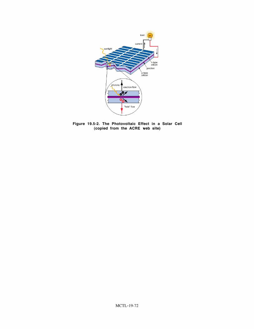
MCTL-19-72
Figure 19.5-2. The Photovoltaic Effect in a Solar Cell(copied from the ACRE web site)

MCTL-19-73
MCTL DATA SHEET 19.5-4. NICKEL-HYDROGEN BATTERY SYSTEMS
Critical TechnologyParameter(s) Specific energy at the cell level > 50 W-hrs/kg.
Life capability: > 1,600 cycles at 80% depth-of-discharge at GEO; or
> 38,000 cycles at 35% depth-of-discharge at LEO.Critical Materials None identified.Unique Test, Production,Inspection Equipment Reliable performance that supports the life capability requires well-controlled
manufacturing equipment and processes, in particular for the nickel electrodes and theirporous substrate. Even limited departure from optimal process parameters cansignificantly degrade performance. These assets are vital to maintaining acceptablenickel-hydrogen battery capability.
Unique Software None identified.Major CommercialApplications Nickel-hydrogen batteries are used in virtually all commercial spacecraft flown in LEO
and GEO. These applications have historically provided a push toward higherperformance due to the relatively large spacecraft mass fraction taken up by batteries.However, the performance levels have not improved substantially in the last 10 years.
Affordability Issues Not an issue.Export ControlReferences USML XV (only if exported as part of a spacecraft).
BACKGROUND
Nickel-hydrogen batteries have been operationally used in space systems since 1983 and are currently the mostcommon energy storage system in satellites. The nickel electrode has been derived and evolved from the nickel-cadmium battery technology that is still used in some very small satellites. The hydrogen electrode has been derivedfrom fuel cell technology. The inherent high stability of these electrodes gives the nickel-hydrogen system its longlife capability at relatively high depth-of-discharge.
Space nickel-hydrogen batteries store their hydrogen at high-pressure and thus are built as pressure vessels. Thepredominant configuration consists of series connected cells that each have their own pressure vessel (“individualpressure vessel” design), but there have been systems flown with multiple series-connected cells contained in a“common pressure vessel” configuration. Other high-pressure variants have been developed but are not in significantuse. Low-pressure nickel-metal hydride batteries represent another variant that has found broad application inconsumer products (e.g., cell phones, laptop computers) but has seen little space use since it trades away some massand life performance for volume and packaging efficiency.
Figure 19.5-3 shows one of the International Space Station (ISS) battery assemblies under construction,illustrating the typical packaging arrangement with an array of interconnected cells on a baseplate, with each held ina sleeve for structural and thermal support.
Nickel-hydrogen batteries in GEO are used for design lifetimes of up to 18 years or 1,600 cycles at depth-of-discharges up to 80 percent. In LEO, the depth-of-discharge is selected as a function of planned mission duration. Anexample is the ISS battery system which supports a minimum of 6.5 years or 38,000 cycles at 35-percent depth-of-discharge.

MCTL-19-74
Figure 19.5-3. Space Station battery assembly under construction
The performance capabilities of space nickel-hydrogen batteries have essentially reached a plateau with littletechnological advancement being pursued. The technology is stable, with the main focus being placed on materialsand process controls to assure that the desired cycle life performance is met. Nickel-hydrogen technology will likelybe largely phased out in favor of Lithium-Ion batteries over the next 10 years.
MCTL-19-75
MCTL DATA SHEET 19.5-5. LITHIUM-ION BATTERY SYSTEMS
Critical TechnologyParameter(s) • Specific energy at the cell level > 130 W-hrs/kg; and
• Battery-level usable specific energy > 65 W-hrs/kg after:
1. 1,600 cycles at 60% depth-of-discharge at GEO; or
2. 38,000 cycles at 25% depth-of-discharge at LEO.Critical Materials None identified.Unique Test, Production,Inspection Equipment Reliable performance that supports the life capability requires well-controlled
manufacturing equipment and processes, in particular for the electrodes.Unique Software None identified.Major CommercialApplications Lithium-Ion batteries are coming into use on commercial spacecraft flown in GEO.
Savings of 100 kg or more drive a strong incentive for such large spacecraft to switchfrom nickel-hydrogen batteries to Lithium-Ion. Small Lithium-Ion batteries have flown onsmall scientific missions.
Affordability Issues Not an issue. Lithium-Ion batteries are expected to be slightly less expensive than thenickel-hydrogen technology being replaced.
Export ControlReferences USML XV (only if exported as part of a spacecraft).
BACKGROUND
On most spacecraft, the battery system is one of the heaviest components and is typically also quite costly.The space battery technologies of choice in the last several decades have been nickel-hydrogen and nickel-cadmium.However, in recent years, space battery manufacturers have begun serious development of Lithium-Ion batteries inorder to realize a substantial mass and some cost advantage.
Lithium-Ion systems have much higher cell voltages than the nickel-based batteries, in the 3–4V range versus1.2–1.5V. These voltages would break down aqueous electrolytes, but are enabled in lithium batteries by the use ofnon-aqueous electrolytes composed of organic liquids and lithium salts. The higher voltage accounts almost entirelyfor the higher specific energy of around 130 W-hrs/kg for Lithium-Ion versus about 55 W-hrs/kg for nickel-hydrogenat the cells level. Other benefits provided by Lithium-Ion are improved compactness, since it is a low-pressuresystem; reduced maximum heat loads; much better charge retention; virtually 100-percent coulombic roundtripefficiency; and inherently lower material costs.
In recent years, Lithium-Ion technology has been pushed along by many commercial applications in consumerproducts (such as cell phones and laptop computers) and developments for electric vehicles. This has led to high-quantity production under high levels of process and material control, which has always been difficult to realize forthe limited-production-volume and raw-material-driven nickel-based systems. Thus, while the Lithium-Ion system isrelatively new and as such carries risk, the promise of a stable and controlled product has made the jump to space usefeasible.
Manufacturers have adapted commercial products into space product lines at the cell level, and life tests havebeen conducted to characterize the life capability as a function of depth-of-discharge and various other conditions andparameters. Life capability for GEO applications has been established and packaging designs have been developed,and the system has been baselined for specific spacecraft programs. Lithium-Ion batteries in GEO can support designlifetimes of up to 18 years or 1,600 cycles at depth-of-discharges of around 60 percent. Appropriate chargemanagement techniques are employed to ensure this life capability.
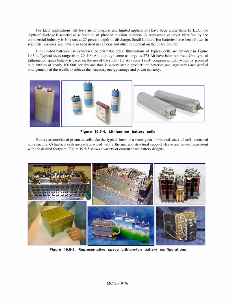
MCTL-19-76
For LEO applications, life tests are in progress and limited applications have been undertaken. In LEO, thedepth-of-dischage is selected as a function of planned mission duration. A representative target identified by thecommercial industry is 10 years at 25-percent depth-of-discharge. Small Lithium-Ion batteries have been flown inscientific missions, and have also been used in cameras and other equipment on the Space Shuttle.
Lithium-Ion batteries use cylindrical or prismatic cells. Illustrations of typical cells are provided in Figure19.5-4. Typical sizes range from 20–100 Ah, although some as large as 275 Ah have been reported. One type ofLithium-Ion space battery is based on the use of the small (1.5 Ah) Sony 18650 commercial cell, which is producedin quantities of nearly 100,000 per day and thus is a very stable product; the batteries use large series and parallelarrangements of these cells to achieve the necessary energy storage and power capacity.
Figure 19.5-4. Lithium-Ion battery cells
Battery assemblies of prismatic cells take the typical form of a rectangular, horizontal stack of cells containedin a structure. Cylindrical cells are each provided with a thermal and structural support sleeve and arrayed consistentwith the desired footprint. Figure 19.5-5 shows a variety of current space battery designs.
Figure 19.5-5. Representative space Lithium-Ion battery configurations
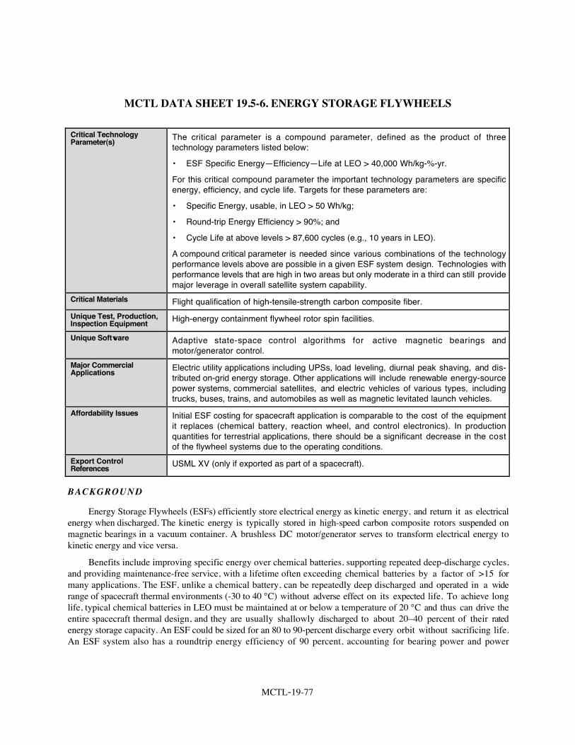
MCTL-19-77
MCTL DATA SHEET 19.5-6. ENERGY STORAGE FLYWHEELS
Critical TechnologyParameter(s) The critical parameter is a compound parameter, defined as the product of three
technology parameters listed below:
• ESF Specific Energy—Efficiency—Life at LEO > 40,000 Wh/kg-%-yr.
For this critical compound parameter the important technology parameters are specificenergy, efficiency, and cycle life. Targets for these parameters are:
• Specific Energy, usable, in LEO > 50 Wh/kg;
• Round-trip Energy Efficiency > 90%; and
• Cycle Life at above levels > 87,600 cycles (e.g., 10 years in LEO).
A compound critical parameter is needed since various combinations of the technologyperformance levels above are possible in a given ESF system design. Technologies withperformance levels that are high in two areas but only moderate in a third can still providemajor leverage in overall satellite system capability.
Critical Materials Flight qualification of high-tensile-strength carbon composite fiber.Unique Test, Production,Inspection Equipment High-energy containment flywheel rotor spin facilities.
Unique Software Adaptive state-space control algorithms for active magnetic bearings andmotor/generator control.
Major CommercialApplications Electric utility applications including UPSs, load leveling, diurnal peak shaving, and dis-
tributed on-grid energy storage. Other applications will include renewable energy-sourcepower systems, commercial satellites, and electric vehicles of various types, includingtrucks, buses, trains, and automobiles as well as magnetic levitated launch vehicles.
Affordability Issues Initial ESF costing for spacecraft application is comparable to the cost of the equipmentit replaces (chemical battery, reaction wheel, and control electronics). In productionquantities for terrestrial applications, there should be a significant decrease in the costof the flywheel systems due to the operating conditions.
Export ControlReferences USML XV (only if exported as part of a spacecraft).
BACKGROUND
Energy Storage Flywheels (ESFs) efficiently store electrical energy as kinetic energy, and return it as electricalenergy when discharged. The kinetic energy is typically stored in high-speed carbon composite rotors suspended onmagnetic bearings in a vacuum container. A brushless DC motor/generator serves to transform electrical energy tokinetic energy and vice versa.
Benefits include improving specific energy over chemical batteries, supporting repeated deep-discharge cycles,and providing maintenance-free service, with a lifetime often exceeding chemical batteries by a factor of >15 formany applications. The ESF, unlike a chemical battery, can be repeatedly deep discharged and operated in a widerange of spacecraft thermal environments (-30 to 40 °C) without adverse effect on its expected life. To achieve longlife, typical chemical batteries in LEO must be maintained at or below a temperature of 20 °C and thus can drive theentire spacecraft thermal design, and they are usually shallowly discharged to about 20–40 percent of their ratedenergy storage capacity. An ESF could be sized for an 80 to 90-percent discharge every orbit without sacrificing life.An ESF system also has a roundtrip energy efficiency of 90 percent, accounting for bearing power and power
MCTL-19-78
processing, which is a significant improvement over nickel-based batteries and competitive with lithium-ionbatteries.
The simultaneous use of ESF for energy storage and for momentum management makes ESF a unique high-leverage application for spacecraft. While ESF is currently a development item for satellites, it benefits satellitemissions by increasing the payload mass fraction, improving electrical efficiency, reducing platform jitter, andimproving reliability. The reduction in platform jitter over a conventional momentum control wheel is achieved bysuspending the ESF rotor on a magnetic bearing. The magnetic suspension provides excellent isolation of the mountfrom the rotating assembly (between –40 to –70 dB) when compared with the vibration transmitted by conventionalrolling element bearing. Of course, magnetic bearings are active-feedback devices and thus require complicatedfeedback and control systems. Precise alignment is also critical.

MCTL-19-79
MCTL DATA SHEET 19.5-7. HEAT TRANSPORT
Critical TechnologyParameter(s)
Fixed conductance heat pipes (FCHP) :Heat Transport Capability: up to 20,000 W-in (e.g., 400 W moved 50''). Heat Transfer Coefficient: 3 W/ °C per inch of interface area (e.g., overall Heat TransferCoefficient could be 10 W/°C for 5'' Evaporator and 20'' Condenser).Operating Temperature Range: -40 to +60 °C (i.e., for ammonia working fluid).Variable conductance heat pipes : same as FCHP plus:Temperature Control: within ± 1°C.Temperature Control Power for Feedback Active Control: 5 W.Diode Heat Pipes : same as FCHP plusReverse Shut Down Energy: 2.5 kJ (depends on HP size and fluid charge).Loop heat pipes :Heat Transport Capability: in microgravity: 1.5 kW moved 50 feet
In 1-G: 1 kW moved downhill 10 feetOverall Heat Transfer Coefficient: > 100 W/ °C.Temperature Control: within ± 5 °C.Temperature Control Power for Feedback Active Control: 50 W.Capillary Pumped Loops :Heat Transport Capability: in microgravity: 1 kW moved 50 feet
In 1-G: 1 kW moved downhill 1 footOverall Heat Transfer Coefficient: 50 W/ °C.Temperature Control: within ± 1 °C.Temperature Control Power for Feedback Active Control: 5 W.Mechanically Pumped Loops :Pump Power versus Transport Power and Distance. Two-phase pumps enjoy a factor of10 less fluid flow rate and less pressure drop requirements.
Critical Materials None identified.Unique Test, Production,Inspection Equipment
Supplier optimized unit operations for specific technologies.
Unique Software Supplier developed design and analysis tools.Major CommercialApplications
GEO-communications S/C use several hundred Heat Pipes each. Higher power S/C canhave 4 deployable radiators with 12 flexible Loop Heat Pipes. Smaller S/C and payloadshave smaller sets of heat pipes for specific cooling needs. Spot cooling of high powercomponents is also important. Terrestrial electronics and HVAC utilize related devicesalthough materials and methods differ.
Affordability Issues Not an issue. Technology provides high value solutions.Export ControlReferences
USML XV (only if exported as part of a spacecraft).

MCTL-19-80
BACKGROUND
Thermal transport technologies, chiefly variants of heat pipes, are critical for removing waste heat (cooling) andregulating optimum operating temperature. The heat pipe group of technologies has enabled significant growth inspacecraft power capability, more efficient packaging of electronics and other equipment, high utilization of theinternal volume of spacecraft, and tight regulation of operating temperatures for sensitive payload and buscomponents. Tight temperature regulation can improve payload performance, sensitivity and accuracy, and providelife extension for items such as batteries.
Most spacecraft thermal architectures utilize the efficient heat transport capability of heat pipes. These devicespassively (with no moving parts) circulate a two-phase fluid (vapor/liquid) to transport and reject heat. Heat pipeseither 1) remove heat from a specific source such as a sensor, cryocooler, or high power electronic component, or2) form a thermal network with up to several hundred per spacecraft to collect heat from all the equipment decks andtransport to and across radiators for heat rejection to space. The heat pipe family includes heat pipes (fixed / constantconductance), Variable Conductance Heat Pipes, Heat Pipe Diodes, Loop Heat Pipes, and Capillary Pumped Loops.Heat pipes can be rigid or include flexible sections.
Mechanically pumped loops sacrifice passive operation with no moving parts to provide higher flow ratesacross larger distances with higher waste heat power levels. Single-phase systems (circulating only liquid) aretypically heavier and require larger pumps with more electrical power. Two-phase systems (circulating liquid andvapor) cool by vaporization and are therefore more efficient and significantly smaller, lighter and consume lesspower.
Greater power levels and power densities may require heat transport systems with more advanced heatacquisition and heat rejection features including flow impingement, spray, and microchannel cooling. Heat pumpswill allow increased radiator heat rejection temperatures.
Most applications at ambient temperatures utilize Al, SS, and Ti with ammonia working fluid. Ethane,methane, nitrogen, neon and helium fluids can be used for cryogenics. Organic fluids support operation at warmambient (100 °C) conditions. Emerging high temperature applications can use water and eventually liquid metals.CTE stable applications may require beryllium pipe or interface materials.
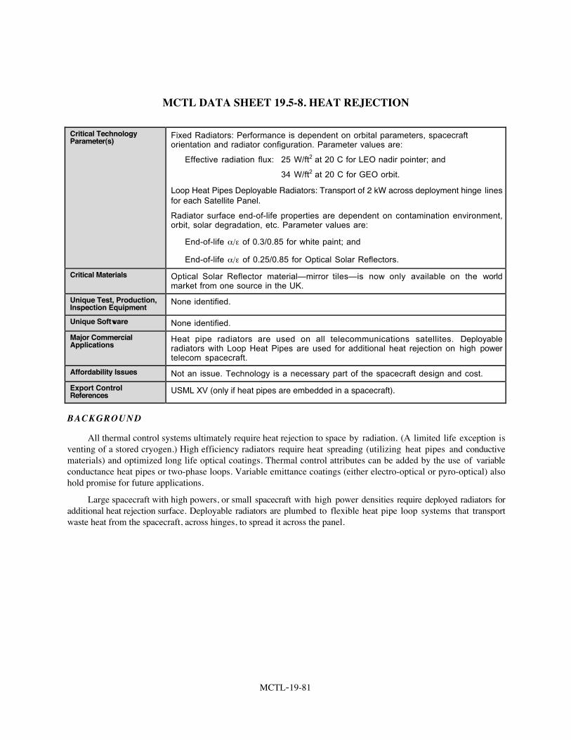
MCTL-19-81
MCTL DATA SHEET 19.5-8. HEAT REJECTION
Critical TechnologyParameter(s)
Fixed Radiators: Performance is dependent on orbital parameters, spacecraftorientation and radiator configuration. Parameter values are:
Effective radiation flux: 25 W/ft2 at 20 C for LEO nadir pointer; and
34 W/ft2 at 20 C for GEO orbit.
Loop Heat Pipes Deployable Radiators: Transport of 2 kW across deployment hinge linesfor each Satellite Panel.Radiator surface end-of-life properties are dependent on contamination environment,orbit, solar degradation, etc. Parameter values are:
End-of-life α/ε of 0.3/0.85 for white paint; and
End-of-life α/ε of 0.25/0.85 for Optical Solar Reflectors.
Critical Materials Optical Solar Reflector material—mirror tiles—is now only available on the worldmarket from one source in the UK.
Unique Test, Production,Inspection Equipment
None identified.
Unique Software None identified.
Major CommercialApplications
Heat pipe radiators are used on all telecommunications satellites. Deployableradiators with Loop Heat Pipes are used for additional heat rejection on high powertelecom spacecraft.
Affordability Issues Not an issue. Technology is a necessary part of the spacecraft design and cost.
Export ControlReferences USML XV (only if heat pipes are embedded in a spacecraft).
BACKGROUND
All thermal control systems ultimately require heat rejection to space by radiation. (A limited life exception isventing of a stored cryogen.) High efficiency radiators require heat spreading (utilizing heat pipes and conductivematerials) and optimized long life optical coatings. Thermal control attributes can be added by the use of variableconductance heat pipes or two-phase loops. Variable emittance coatings (either electro-optical or pyro-optical) alsohold promise for future applications.
Large spacecraft with high powers, or small spacecraft with high power densities require deployed radiators foradditional heat rejection surface. Deployable radiators are plumbed to flexible heat pipe loop systems that transportwaste heat from the spacecraft, across hinges, to spread it across the panel.

MCTL-19-82
MCTL DATA SHEET 19.5-9. THERMAL STORAGE
Critical TechnologyParameter(s) Ambient phase-change materials (PCMs):
PCM heat of fusion: 30 Wh/lb;
Fusion temperature: available every few degrees;
Effective thermal storage capacity: 15 Wh/lb; and
Through conductance: 30 W/ °C.
Cryogenic PCMs:
PCM heat of fusion: 1 to 3 Wh/lb;
Fusion temperature: available at intervals;
Effective thermal storage capacity: 0.2 to 1 Wh/lb; and
Through conductance: 15 W/ °C.Critical Materials None identified.Unique Test, Production,Inspection Equipment None identified for ambient applications. Cryogenic beryllium containers require
assembly using specialized diffusion weld techniques.Unique Software None identified.Major CommercialApplications Terrestrial industrial applications of PCM typically utilize hydrated salts that provide too
high a corrosion risk for space containment.Affordability Issues Not an issue. Technology provides high value solutions.Export ControlReferences USML XV.
BACKGROUND
Thermal storage devices permit cyclic or pulse operation of high power components. This energy is stored inan intermediate thermal storage device, which is then cooled at a much lower steady state rate. Thermal storagedevices can also be applied to make micro-satellites with low system mass, thermally more stable during orbitalenvironmental variations. Thermal storage devices typically use melting and freezing of a wax (PCM-phase changematerial) within a conductive matrix to store energy. Design of a thermal storage device requires selection of a PCMthat melts/freezes at the desired control temperature.
Total PCM contained must provide total energy storage for the periods of high power followed by the periodsof regeneration. The conductive matrix must be optimized to minimize temperature overshoot at the source, as heatconducts to the PCM moving melt boundary. Conductive matrixes vary from aluminum honeycomb and foam, tohigh conductivity carbon foam and fiber bundles. Container envelopes may be bonded assemblies, but hermeticallysealed, welded thin walled aluminum vessels are preferred.
Typical ambient temperature PCMs include hexadecane (Melting Point=18 °C), and eicosane (MP=36 °C).Cryogenic PCMs can include nitrogen, which has a freezing point at 63 K and a solid-solid transition at 35 K. Othercryogenics can include elements such as argon, which melts at 87 K.
A wide range of organic waxes, which provide the desired melt temperature, service ambient electronics andsensors. Past Russian applications have used low temperature eutectic alloys for warm ambient temperatures. Low

MCTL-19-83
cryogenic sensors can utilize the freezing of gases and elements such as nitrogen, neon, or even helium. Cryogenicapplications may require beryllium containers.

MCTL-19-84
MCTL DATA SHEET 19.5-10. CRYOCOOLERS
Critical TechnologyParameter(s) Cooling capacity 0.1 to 0.5 W at 10 K
2 to 5 W at 35 K
> 10 W at 100 K
Specific power < 1000 W/W at 10 K
< 60 W/W at 35 K
< 8 W/W at 100 K
Cooler mass < 5 kgCritical Materials None identified. (Materials are similar to those used in other aerospace components, no
unique materials specific to cryocooler development).Unique Test, Production,Inspection Equipment None identified. [Ground Support Equipment (GSE) to support cryocooler testing is
tailored to individual designs typical of other aerospace hardware.]Unique Software Algorithms together with sensors that sense mechanical vibrations, process the
information and then relay commands to counter vibrations.Major CommercialApplications Commercial satellites.
Affordability Issues Very expensive as a result of the high reliability and relatively low numbers underproduction (~$1 million) source: European Space Agency.
Export ControlReferences WA ML 20; WA Cat 6A and Cat 9A; USML XV; CCL Cat 6A and Cat 9A.
BACKGROUND
Space thermal control problems require a range of thermal control components. In certain types of spacecraft,such as those used in Earth-observing applications, infrared detectors and optics need to be very cold while co-existing with much warmer components. Many NASA and Air Force near-term, future and advanced spaceinstruments and programs depend on the successful use of long-life, low-vibration space cryocoolers to meet theirscientific objectives.
Cryocoolers are an enabling technology for numerous military and civil (e.g., NASA) space missions. Theyprovide a cold heat sink by removing the heat in the cold area and dissipating it in the warm area. Heat pumping canbe achieved using an open- or closed-cycle configuration. The open cycle corresponds to the use of stored cryogens,where the work is performed on the ground before the mission by a liquefier. The closed cycle relies on the use ofmechanical coolers, where the work is done continuously during satellite operation. In all cases, some electronics isrequired to monitor the temperature and keep it constant, and drive the cooler mechanisms. In a cryocooler,mechanical work produced by moving parts is transformed into refrigerating power.
While there are many ways to classify a cryocooler, the most widely used is to distinguish between regenerativecycles (Stirling, pulse tube and Gifford coolers) and recuperative cycles (Joule-Thomson or Brayton coolers). Theregenerative coolers are based on a pressure wave generated by a compressor (usually mechanical) and a cold finger,using a mobile (Stirling, Gifford) or a fixed (Pulse Tube) regenerator. The heat is extracted at the cold end when thegas expands, and rejected at the warm end when the gas is compressed. The recuperative cycles use the enthalpydifference between high and low pressure gas. The Brayton cycle cooler uses a cold turbine to expand the gas,whereas the Joule-Thomson coolers use the expansion though an orifice, and the properties of real gas to get the

MCTL-19-85
cooling effect. Being irreversible, the Joule-Thomson cooler (normally coupled to Stirling units) is less efficient thatthe Brayton type, but it is simpler.
Initial cryocoolers for space applications were based on the Stirling cycle or on the Joule-Thomson expansion,but more recently a variation using a pulse tube cold head with the Stirling cycle compressors has been used in theUnited States, due to its lack of moving parts and thus reduced vibration levels.
Cryogenic detectors have driven the utilization of cryogenics in space thus determining the requirements interms of operating temperature, temperature stability and architecture of the payload system. This trend is now wellestablished across the electromagnetic spectrum. Applications involving the lower energy end of the electromagneticspectrum (i.e., submillimeter wave and infrared) are the ones that benefit most from the utilization of cryogenicdetectors and therefore cryocoolers. Besides cryogenic detectors another technology that will require cryogenics is inthe area of telecommunications. Progress in High-Temperature Superconductors has opened new perspectives for thefabrication of radio-frequency super-conducting devices such as filters, delay lines, resonators and antennas. Thesedevices provide the capability to improve the performance of telecommunications satellite.
Beside the cryocooler itself, the cryocooler’s control electronics and associated software are critical elements of astate-of-the-art cryocooler system in monitoring and processing sensor inputs in order to provide feedback to reducevibration levels.
Cryogenic thermal systems interface sensors with mechanical coolers with operating ranges from 200 to 2 K.They include heat transport devices, thermal switches and diodes, thermal storage, mechanical supports, thermalisolation, and thermal insulation. This hardware is critical in that it must provide excellent thermal interfaces whileminimizing transmission of mechanical forces.

MCTL-19-87
SECTION 19.6—LAUNCH PROPULSION FOR SPACE SYSTEMS
Highlights
• Space Launch Propulsion Systems are key critical elements of U.S. national security and U.S. economicpower.
• Many of the technologies used in space launch propulsion systems are used in both commercial and defenseapplications therefore they are dual use technologies.
• Improving the specific impulse, Isp, of propellants has been a major factor in the United States maintaining atechnological lead in this area.
• There are two basic types of launch propulsion systems—Solid Rocket Motor (SRM) and Liquid RocketMotor (LRM). Many of their respective technologies are quite different.
• A third category of rocket engines is hybrid rocket motors (HRM)—essentially an SRM in which onechemical, generally the oxidizer, is a liquid.
• Propulsion technologies include propellants and propellant ingredients, turbo-machinery, cases, nozzles,actuators and controls, and design and fabrication of specific components.
• Modern launch propulsion technology development principles began to be understood in the early 20th
century, and in most regards, today’s technology is a refinement (albeit a significant one) of Germany’sWorld War II V2 rockets.
• New refinements include advanced propellants and chemicals, new bearing designs, and technologies usingexotic materials for combustion chambers and nozzles.
• Increasingly, design codes, fabrication techniques, and specialized test equipment are critical elements of thetechnologies.
• Ramjet technology currently used in tactical missiles, has the potential to be used in launch propulsion.
• Improving the performance of hybrid systems will have a significant effect on the overall thrust to weightratio and therefore payload costs.
• Emerging critical propulsion technology areas include chemical, low-thrust electrical, and nuclear thermal.
• Nuclear thermal propulsion appears attractive for high-energy upper stage propulsion and for co-generatedelectrical systems.
• Further developments continue in high-energy-density propulsion materials, improved propellant bonding,and advanced cryocooling and storage.
OVERVIEW
The launch propulsion technology section encompasses many individual critical technologies that are requiredto support and maintain our military capabilities. The list above identifies the thirteen (13) specific technologieswith critical parameters and parameter values needed to maintain this capability. These include: High-EnergyPropellant Ingredients, Ramjet Launch Propulsion, Liquid Rocket Engines, Liquid Rocket Engines CombustionChamber Devices, Liquid Rocket Engine Nozzles and Exit Cone Technology, Liquid Rocket Engine TurboMachinery, Rocket Engine Nozzle Technology, Solid Rocket Engines, Solid Rocket Propulsion, Composite MotorCases, Thrust Vector Actuation Systems, Thrust Vector Control Systems, and High-Energy Propellant Ingredients.
MCTL-19-88
All of these critical technologies are dual use technologies since commercial satellites use the sametechnologies as required for those of military needs. Therefore, careful consideration has been given to what is trulycritical in military applications so as to minimize the economic impact of any limitations that might result bygovernmental use of these militarily critical technologies and respective parameters.
BACKGROUND
There are two main types of rocket engine in use today. They are solid and liquid propellant rocket engines.There are also some hybrid rocket engines which combine portions of these two types. A hybrid rocket burns amixture of solid fuel and liquid or gaseous oxidizer. A hybrid rocket engine almost matches the high specific impulseof liquid propellant rocket, and requires at most half the number of expensive turbo-pumps. Most hybrid designsforgo turbo-pumps entirely with the liquid oxygen feeding into the fuel combustion chamber by tank pressure.
The word propellant does not mean simply fuel; it means both fuel and oxidizer. The fuel is the chemicalrockets burn mechanism, but, for burning to take place, an oxidizer (oxygen) must be present. Jet engines drawoxygen into their engines from the surrounding air. Rockets do not have the luxury that jet planes have; they mustcarry oxygen with them into space, where there is no air.
1 . Liquid Rocket Engines
In a liquid rocket, the propellants, the fuel and the oxidizer, are stored separately as liquids and are pumped intothe combustion chamber of the nozzle where burning occurs. Under normal temperature conditions, the propellantsdo not burn; but they will burn when exposed to a source of heat provided by an igniter. Once the burning starts, itproceeds until the propellant flow is interrupted. Thrust can be stopped by turning off the flow of propellants. Liquidrockets tend to be heavy and complex because of the pumps and storage tanks.
Nozzles are used to on both liquid and solid rocket engines to increase the acceleration of the gases as they leavethe rocket and thereby maximize the thrust. It does this by cutting down the opening through which the gases canescape. The size of the opening can be varied depending on the desired thrust and other requirements.
As with the inside of the rocket case, insulation is needed to protect the nozzle from the hot gases. The usualinsulation is one that gradually erodes as the gas passes through. Small pieces of the insulation get very hot andbreak away from the nozzle. As they are blown away, heat is carried away with them.
The fuel of a liquid-propellant rocket is usually kerosene or liquid hydrogen; the oxidizer is usually liquidoxygen. They are combined inside a cavity called the combustion chamber. Here the propellants burn and build uphigh temperatures and pressures, and the expanding gas escapes through the nozzle at the lower end. To get the mostpower from the propellants, they must be mixed as completely as possible. Small injectors (nozzles) on the roof ofthe chamber spray and mix the propellants at the same time. Because the chamber operates under high pressures, thepropellants need to be forced inside. Powerful, lightweight turbine pumps between the propellant tanks andcombustion chambers take care of this job.
With any rocket, and especially with liquid-propellant rockets, weight is an important factor. In general, theheavier the rocket, the more the thrust needed to get it off the ground. Because of the pumps and fuel lines, liquidengines are much heavier than solid engines.
One especially good method of reducing the weight of liquid engines is to make the exit cone of the nozzle outof very lightweight metals. However, the extremely hot, fast-moving gases that pass through the cone would quicklymelt thin metal. Therefore, a cooling system is needed. A highly effective though complex cooling system that isused with some liquid engines takes advantage of the low temperature of liquid hydrogen. Hydrogen becomes a liquidwhen it is chilled to –2530 °C. Before injecting the hydrogen into the combustion chamber, it is first circulatedthrough small tubes that lace the walls of the exit cone. In a cutaway view, the exit cone wall looks like the edge ofcorrugated cardboard. The hydrogen in the tubes absorbs the excess heat entering the cone walls and prevents it frommelting the walls away. It also makes the hydrogen more energetic because of the heat it picks up. This kind ofcooling system is regenerative cooling.
MCTL-19-89
Controlling the thrust of an engine is very important to launching payloads (cargoes) into orbit. Too muchthrust or thrust at the wrong time can cause a satellite to be placed in the wrong orbit or set too far out into space tobe useful. Too little thrust can cause the satellite to fall back to Earth.
Liquid-propellant engines control the thrust by varying the amount of propellant that enters the combustionchamber. A computer in the rocket’s guidance system determines the amount of thrust that is needed and controls thepropellant flow rate. On more complicated flights, such as going to the Moon, the engines must be started andstopped several times. Liquid engines do this by simply starting or stopping the flow of propellants into thecombustion chamber.
There are two metal or composite tanks required for a liquid rocket engine, holding the fuel and oxidizerrespectively. Due to properties of these two liquids, they are typically loaded into their tanks just prior to launch.The separate tanks are necessary, for many liquid fuels burn upon contact. Upon a set launching sequence two valvesopen, allowing the liquid, hitherto blocked, to flow down the pipe-work. If these valves simply opened allowing theliquid propellants to flow into the combustion chamber at their own leisure, a weak (if any at all) thrust productionwould incur as well as an unstable flow rate (leading to an unstable thrust rate). Two solutions have been devised tosolve this problem: (1) a pressurized gas feed and (2) a turbopump feed.
Figure 19.6-1 shows a typical liquid rocket engine similar to the type used in space launches of the shuttle. Alot of the following material which illustrates the basics of liquid rocket engine technology is taken from the NASAweb site: http://www.grc.nasa.gov/WWW/K-12/airplane/rockth.html .
Figure 19.6-1. Courtesy of the NASA web site at: http://www.grc.nasa.gov/WWW/K- 12/airplane/rockth.html
The thrust equation works for both liquid and solid rocket engines. There is also an efficiency parameter calledthe specific impulse which works for both types of rockets and greatly simplifies the performance analysis forrockets.
2 . Solid Rocket Engines
A solid-propellant rocket has the simplest form of engine. It has a nozzle, a case, insulation, propellant, and anigniter. The case of the engine is usually a relatively thin metal that is lined with insulation to keep the propellantfrom burning through. The propellant itself is packed inside the insulation layer.
Many solid-propellant rocket engines feature a hollow core that runs through the propellant. Rockets that donot have the hollow core must be ignited at the lower end of the propellants and burning proceeds gradually from oneend of the rocket to the other. In all cases, only the surface of the propellant burns. However, to get higher thrust, ahollow core is used. This increases the surface of the propellants available for burning. The propellants burn from

MCTL-19-90
the inside out at a very high rate, and the gases produced escape the engine at much higher speeds. This gives agreater thrust. Some propellant cores are star shaped to increase the burning surface even more.
To fire solid propellants, many kinds of igniters can be used. Fire-arrows were ignited by fuses, but sometimesthese ignited too quickly and burned the rocket launcher. A far safer and more reliable form of ignition used is onethat employs electricity. An electric current, coming through wires from some distance away, heats up a special wireinside the rocket. The wire raises the temperature of the propellant it is in contact with to the combustion point.
Solid-propellant rockets are not as easy to control as liquid rockets. Once started, the propellants burn untilthey are gone. They are very difficult to stop or slow down part way into the burn. Sometimes fire extinguishers arebuilt into the engine to stop the rocket in flight. But using them is a tricky procedure and doesn’t always work.Some solid-fuel engines have hatches on their sides that can be cut loose by remote control to release the chamberpressure and terminate thrust.
The burn rate of solid propellants must be carefully planned in advance. At first, there is a very large surfaceavailable for burning, but as the points of the star burn away, the surface area is reduced. For a time, less of thepropellant burns, and this reduces thrust. The Space Shuttle uses this technique to reduce vibrations early in its flightinto orbit.
Solid rocket engines are somewhat different in nature from liquid engines, but also have a specific set ofadvantages and drawbacks. In solid rocket motors, the fuel and oxidizer are chemically premixed to form a solid fuelgrain. By simply igniting this substance, the oxidizer and fuel in the solid react and produce the high-energycombustion gases desired. A variety of designs for the central burning port of the solid fuel can be created so as toproduce the desired thrust performance. Solid rockets provide good thrust and are the simplest systems available. Onthe down side, they also are fairly inefficient fuel burners and cannot be throttled. In some cases there may also beexplosion dangers since the oxidizer and fuel are not separated.
Solid rocket propellants, which are dry to the touch, contain both the fuel and oxidizer combined together in thechemical itself. The propellants are mixed together and packed into a solid cylinder. Usually the fuel is a mixture ofhydrogen compounds and carbon and the oxidizer is made up of oxygen compounds (see Figure 19.6-2).
Figure 19.6-2. Illustrates a solid rocket thrust engine, taken from the NASA web site:http://www.grc.nasa.gov/WWW/K-12/airplane/srockth.html
The amount of thrust produced by the rocket depends on the design of the nozzle. The smallest cross-sectionalarea of the nozzle is called the throat of the nozzle. The hot exhaust flow is choked at the throat, which meansthat the Mach number is equal to 1.0 in the throat and the mass flow rate m dot is determined by the throat area.The area ratio from the throat to the exit Ae sets the exit velocity Ve and the exit pressure pe.
The exit pressure is only equal to free stream pressure at some design condition. We must, therefore, use thelonger version of the generalized thrust equation to describe the thrust of the system. If the free stream pressure isgiven by p0, the thrust F equation becomes:
F = m dot * Ve + (pe - p0) * Ae

MCTL-19-91
There is no free stream mass times free stream velocity term in the thrust equation because no external air isbrought on board. Since the oxidizer is mixed into the propellant, solid rockets can generate thrust in a vacuumwhere there is no other source of oxygen. That’s why a rocket will work in space, where there is no surrounding air,and a gas turbine or propeller will not work. Turbine engines and propellers rely on the atmosphere to provide theoxygen for combustion and as the working fluid in the generation of thrust.
The thrust equation given above works for both liquid and solid rocket engines. There is also an efficiencyparameter called the specific impulse which works for both types of rockets and greatly simplifies the performanceanalysis for rocket engines (Ref. 1).
3 . Hybrid Rocket Engines
Hybrid rockets combine elements from both types of liquid and solid rockets. In a hybrid rocket, a gaseous orliquid oxidizer is stored in a tank separate from a solid fuel. The fuel or fuel grain is placed inside a pressure chamberwhich lies between an oxidizer injector and the exit nozzle. The solid grain is hollowed out in the same fashion toproduce a combustion port, very similar to that of a solid rocket motor type system. Unless the fuel is hypergolic(spontaneously combustible in the presence of an oxidizer), the fuel must be initially ignited in order to vaporizesome of the fuel into a region just above the solid surface. Then, by injecting the oxidizer at a high mass flow rateand pressure into the pressure chamber or combustion port area, the oxidizer and fuel are free to react just above thesurface of the fuel grain. The high energy released and the high temperature attained both increase the energy in theflow and sustain the solid fuel vaporization. The combustion gases pass down the remainder of the combustion portand are expanded via the nozzle. By changing the flow rate of the oxidizer, the total production of combustion gasesand the energy going into them will be changed in a like fashion (increasing or decreasing). This fact demonstratesthat hybrid rockets can be throttled. Given a simple ignition system that would efficiently initiate fuel burning priorto injecting the oxidizer, it also shows that hybrid rockets have start-stop-restart capabilities which can be a majorattribute for some applications.
On the down side, the nature of the system renders itself to marginally higher combustion inefficiencies andalso to variations in specific impulse. This has much to do with the incompleteness of the mixing in the activecombustion zone above the solid fuel surface. These effects are not so bad however; as far as specific impulse isconcerned. Typical performance numbers are not difficult to find: for liquid systems, typical impulses can rangefrom 300 sec up to 400 sec for the SSME; typical solid systems operate at a specific impulse of between 200–270sec. Performances generated thus far for experimental hybrid test engines lie in the range of 275–350 sec. Moreover,it is not beyond possibility that further dedicated research and development of hybrid rocket motors will relieve someof the inefficiency problems and therefore boost the performance figures even higher. Another disadvantage to hybridsis that there will usually be unburned fuel slivers remaining after burning; however, this effect also plagues solidrockets. Clearly in many of these respects, the disadvantages of hybrid rockets are non-critical, and many are clearlynot disadvantages with respect to solid systems.
The major benefit of solid rockets over hybrid rockets (and liquid systems, too) is their simplicity. In hybridsystems, then, it seems that higher complexity is the price paid for better performance. However, the performance forthese rockets is approaching that of liquid systems. Furthermore, hybrid rocket systems require support for only onefluid system, including tanks, valves, regulators, etc. In other words, although hybrid rockets are more complex thansolid systems, they compare in performance to liquid systems while requiring only half of the “plumbing.” Thisvastly reduces the overall systems weight and cost, while increasing its reliability (there will be fewer parts to fail).Hybrid rocket systems are also safer to produce and store, can be more ecologically safe with proper propellantchoice, and the fuel grain, being inert, is stronger then manufactured solid propellant grains (for solid rockets), and istherefore more reliable. Finally the solid fuel grain of the hybrid gives it volumetric sizing advantages over thetankage required for liquid systems. Clearly, hybrid rocket motors offer numerous benefits at a small price. It is inlight of this prospect for hybrid rockets, that a project group has been formed at the University of Illinois to designand test a test-scale hybrid rocket motor (Ref. 2).

MCTL-19-92
REFERENCES
1. http://www.grc.nasa.gov/WWW/K-12/airplane/srockth.html
2. http://stimpy.cen.uiuc.edu/soc/isds/hybrid/intro.htm
MCTL-19-93
LIST OF MCTL TECHNOLOGY DATA SHEETS19.6. LAUNCH PROPULSION FOR SPACE SYSTEMS
19.6-1 High-Energy Propellant ...........................................................................................MCTL-19-95
19.6-2 High-Energy Propellant Ingredients............................................................................MCTL-19-99
19.6-3 Liquid Rocket Engines .......................................................................................... MCTL-19-101
19.6-4 Liquid Rocket Engines Combustion Chamber Devices ................................................ MCTL-19-106
19.6-5 Liquid Rocket Engine Nozzle (Exit Cone) Technology ................................................ MCTL-19-110
19.6-6 Liquid Rocket Engine Turbomachinery..................................................................... MCTL-19-114
19.6-7 Liquid Rocket Engine Injectors ............................................................................... MCTL-19-117
19.6-8 Solid Rocket Engine Nozzle Technology .................................................................. MCTL-19-119
19.6-9 Solid Rocket Propulsion........................................................................................ MCTL-19-122
19.6-10 Composite Motor Cases ........................................................................................ MCTL-19-124
19.6-11 Thrust Vector Actuation Systems............................................................................ MCTL-19-127
19.6-12 Thrust Vector Control Systems............................................................................... MCTL-19-128
19.6-13 Ramjet Launch Propulsion..................................................................................... MCTL-19-132
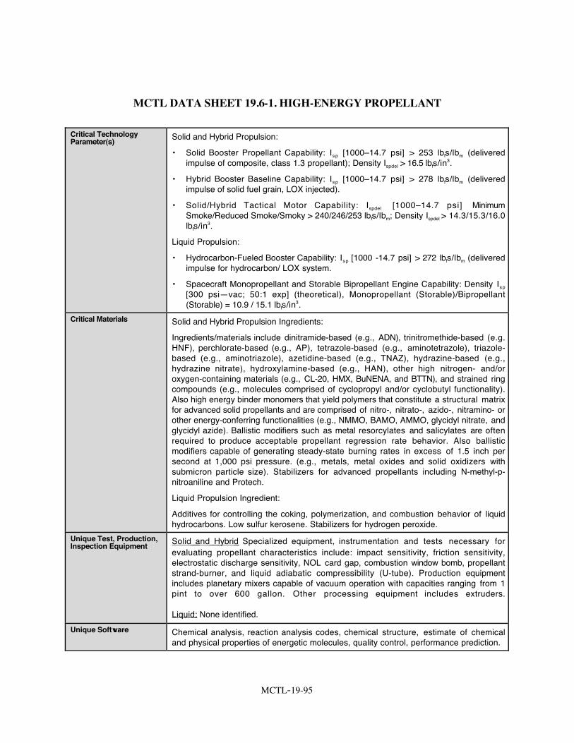
MCTL-19-95
MCTL DATA SHEET 19.6-1. HIGH-ENERGY PROPELLANT
Critical TechnologyParameter(s) Solid and Hybrid Propulsion:
• Solid Booster Propellant Capability: Is p [1000–14.7 psi] > 253 lbfs/lbm (deliveredimpulse of composite, class 1.3 propellant); Density Ispdel > 16.5 lbfs/in3.
• Hybrid Booster Baseline Capability: Is p [1000–14.7 psi] > 278 lbfs/lbm (deliveredimpulse of solid fuel grain, LOX injected).
• Solid/Hybrid Tactical Motor Capability: Ispdel [1000–14.7 psi] MinimumSmoke/Reduced Smoke/Smoky > 240/246/253 lbfs/lbm; Density Ispdel > 14.3/15.3/16.0lbfs/in3.
Liquid Propulsion:
• Hydrocarbon-Fueled Booster Capability: Is p [1000 -14.7 psi] > 272 lbfs/lbm (deliveredimpulse for hydrocarbon/ LOX system.
• Spacecraft Monopropellant and Storable Bipropellant Engine Capability: Density Is p[300 psi—vac; 50:1 exp] (theoretical), Monopropellant (Storable)/Bipropellant(Storable) = 10.9 / 15.1 lbfs/in3.
Critical Materials Solid and Hybrid Propulsion Ingredients:
Ingredients/materials include dinitramide-based (e.g., ADN), trinitromethide-based (e.g.HNF), perchlorate-based (e.g., AP), tetrazole-based (e.g., aminotetrazole), triazole-based (e.g., aminotriazole), azetidine-based (e.g., TNAZ), hydrazine-based (e.g.,hydrazine nitrate), hydroxylamine-based (e.g., HAN), other high nitrogen- and/oroxygen-containing materials (e.g., CL-20, HMX, BuNENA, and BTTN), and strained ringcompounds (e.g., molecules comprised of cyclopropyl and/or cyclobutyl functionality).Also high energy binder monomers that yield polymers that constitute a structural matrixfor advanced solid propellants and are comprised of nitro-, nitrato-, azido-, nitramino- orother energy-conferring functionalities (e.g., NMMO, BAMO, AMMO, glycidyl nitrate, andglycidyl azide). Ballistic modifiers such as metal resorcylates and salicylates are oftenrequired to produce acceptable propellant regression rate behavior. Also ballisticmodifiers capable of generating steady-state burning rates in excess of 1.5 inch persecond at 1,000 psi pressure. (e.g., metals, metal oxides and solid oxidizers withsubmicron particle size). Stabilizers for advanced propellants including N-methyl-p-nitroaniline and Protech.
Liquid Propulsion Ingredient:
Additives for controlling the coking, polymerization, and combustion behavior of liquidhydrocarbons. Low sulfur kerosene. Stabilizers for hydrogen peroxide.
Unique Test, Production,Inspection Equipment Solid and Hybrid Specialized equipment, instrumentation and tests necessary for
evaluating propellant characteristics include: impact sensitivity, friction sensitivity,electrostatic discharge sensitivity, NOL card gap, combustion window bomb, propellantstrand-burner, and liquid adiabatic compressibility (U-tube). Production equipmentincludes planetary mixers capable of vacuum operation with capacities ranging from 1pint to over 600 gallon. Other processing equipment includes extruders.
Liquid: None identified.Unique Software Chemical analysis, reaction analysis codes, chemical structure, estimate of chemical
and physical properties of energetic molecules, quality control, performance prediction.
MCTL-19-96
Major CommercialApplications Spacecraft propulsion.
Affordability Issues None identified.Export ControlReferences WA ML 8; USML IV; MTCR 4.
BACKGROUND
Since the earliest days of discovery and experimentation, rockets have evolved from simple gunpowder devicesinto giant vehicles capable of traveling into outer space. Rockets have opened the universe to direct exploration byhumankind. These rockets are propelled by a variety of fuel mixtures. The array includes: Liquid Propellants, SolidPropellants and Hybrids. The Hybrid propellant engines represent an intermediate group between solid and liquidpropellant engines, which will be described in the next section.
Propellant is the chemical mixture burned to produce thrust in rockets and consists of a fuel and an oxidizer.Fuel is a substance, which burns when combined with oxygen producing gas for propulsion. An oxidizer is an agentthat releases oxygen for combination with a fuel. Propellants are classified according to their state—liquid, solid, orhybrid.
The gauge for rating the efficiency of rocket propellants is specific impulse, stated in seconds. Specific impulseindicates how many pounds (or kilograms) of thrust are obtained by the consumption of one pound (or kilogram) ofpropellant in one second. Specific impulse is characteristic of the type of propellant, however, its exact value willvary to some extent with the operating conditions and design of the rocket engine.
Liquid Propellants. In a liquid propellant rocket, the fuel and oxidizer are stored in separate tanks, and arefed through a system of pipes, valves, and turbopumps to a combustion chamber where they are combined andburned to produce thrust. Liquid propellant engines are more complex then their solid propellant counterparts,however, they offer several advantages. By controlling the flow of propellant to the combustion chamber, the enginecan be throttled, stopped, or restarted. The restarting is a key issue for on-orbit maneuvering.
A good liquid propellant is one with a high specific impulse or, stated another way, one with a high speed ofexhaust gas ejection. This implies a high combustion temperature and exhaust gases with small molecular weights.However, there is another important factor, which must be taken into consideration: the density of the propellant.Using low-density propellants means that larger storage tanks will be required, thus increasing the mass of thelaunch vehicle. Storage temperature is also important. A propellant with a low storage temperature, i.e., a cryogenic,will require thermal insulation, thus further increasing the mass of the launcher. The toxicity of the propellant islikewise important. Safety hazards exist when handling, transporting, and storing highly toxic compounds. Also,some propellants are very corrosive, however, materials that are resistant to certain propellants have been identifiedfor use in rocket construction.
Liquid propellants used by NASA and in commercial launch vehicles can be classified into three types:petroleum, cryogenics, and hypergolics.
Petroleum fuels are those refined from crude oil and are a mixture of complex hydrocarbons, i.e. organiccompounds containing only carbon and hydrogen. The petroleum used as rocket fuel is kerosene, or a type of highlyrefined kerosene called RP-1 (refined petroleum). It is used in combination with liquid oxygen as the oxidizer.
RP-1 and liquid oxygen are used as the propellant in the first-stage boosters of the Atlas/Centaur and Deltalaunch vehicles. It also powered the first-stages of the Saturn 1B and Saturn V rockets. RP-1 delivers a specificimpulse considerably less than cryogenic fuels.
Cryogenic propellants are liquefied gases stored at very low temperatures, namely liquid hydrogen (LH2) asthe fuel and liquid oxygen (LO2) as the oxidizer. LH2 remains liquid at temperatures of -423 °F (-253 °C) and LO2remains in a liquid state at temperatures of -298 °F (-183 °C).
Because of the low temperatures of cryogenic propellants, they are difficult to store over long periods of time.For this reason, they are less desirable for use in military rockets, which must be kept launch ready for months at a

MCTL-19-97
time. Also, liquid hydrogen has a very low density (0.59 lbs/gal) and, therefore, requires a storage volume manytimes greater than other fuels. Despite these drawbacks, the high efficiency of liquid hydrogen/liquid oxygen makesthese problems worth coping with when reaction time and storability are not too critical. Liquid hydrogen delivers aspecific impulse about 40-percent higher than other rocket fuels.
Liquid hydrogen and liquid oxygen are used as the propellant in the high efficiency main engines of the spaceshuttle. LH2/LO2 also powered the upper stages of the Saturn V and Saturn lB rockets as well as the second stage ofthe Atlas/Centaur launch vehicle, the United States’ first LH2/LO2 rocket (1962).
Hypergolic propellants are fuels and oxidizers, which ignite spontaneously on contact with each other andrequire no ignition source. The easy start and restart capability of hypergolics make them ideal for spacecraftmaneuvering systems. Also, since hypergolics remain liquid at normal temperatures, they do not pose the storageproblems of cryogenic propellants. Hypergolics are highly toxic and must be handled with extreme care.
Hypergolic fuels commonly include hydrazine, monomethyl hydrazine (MMH) and unsymmetrical dimethylhydrazine (UDMH). The oxidizer is typically nitrogen tetroxide (N2O4) or nitric acid (HNO3). UDMH is used inmany Russian, European, and Chinese rockets while MMH is used in the orbital maneuvering system (OMS) andreaction control system (RCS) of the Space Shuttle orbiter. The Titan family of launch vehicles and the second stageof the Delta use a fuel called Aerozine 50, a mixture of 50-percent UDMH and 50-percent hydrazine.
Hydrazine is also frequently used as a mono-propellant in catalytic decomposition engines. In these engines, aliquid fuel decomposes into hot gas in the presence of a catalyst. The decomposition of hydrazine producestemperatures of about 1700 °F and a specific impulse of about 230 or 240 seconds.
Solid Propellants. Solid propellant motors are the simplest of all rocket designs. They consist of a casing,usually steel, filled with a mixture of solid compounds (fuel and oxidizer), which burns at a rapid rate, expelling hotgases from a nozzle to produce thrust. When ignited, a solid propellant burns from the center out towards the sides ofthe casing. The shape of the center channel determines the rate and pattern of the burn, thus providing a means tocontrol thrust. Unlike liquid propellant engines, solid propellant motors cannot be shut down. Once ignited, theywill burn until all the propellant is exhausted.
There are two families of solids propellants: homogeneous and composite. Both types are dense, stable atordinary temperatures, and easily storable.
Homogeneous propellants are either simple base or double base. A simple base propellant consists of a singlecompound, usually nitrocellulose, which has both an oxidation capacity and a reduction capacity. Double basepropellants usually consist of nitrocellulose and nitroglycerine, to which a plasticiser is added. Homogeneouspropellants do not usually have specific impulses greater than about 210 seconds under normal conditions. Theirmain asset is that they do not produce traceable fumes and are, therefore, commonly used in tactical weapons. Theyare also often used to perform subsidiary functions such as jettisoning spent parts or separating one stage fromanother.
Modern composite propellants are heterogeneous powders (mixtures), which use a crystallized or finely groundmineral salt as an oxidizer, often ammonium perchlorate, which constitutes between 60 percent and 90 percent of themass of the propellant. The fuel itself is aluminum. The propellant is held together by a polymeric binder, usuallypolyurethane or polybutadienes. Additional compounds are sometimes included, such as a catalyst to help increasethe burning rate, or other agents to make the powder easier to manufacture. The final product is rubber-like substancewith the consistency of a hard rubber eraser.
Solid propellant motors have a variety of uses. Small solids often power the final stage of a launch vehicle, orattach to payloads to boost them to higher orbits. Medium solids such as the Payload Assist Module (PAM) and theInertial Upper Stage (IUS) provide the added boost to place satellites into geosynchronous orbit or on planetarytrajectories.
The Titan, Delta, and Space Shuttle launch vehicles use strap-on solid propellant rockets to provide added thrustat liftoff. The Space Shuttle uses the largest solid rocket motors ever built and flown. Each booster contains1,100,000 lbs (499,000 kg) of propellant and can produce up to 3,300,000 lbs (14,680,000 Newtons) of thrust.

MCTL-19-98
Hybrid Propellants. Hybrid propellant engines represent an intermediate group between solid and liquidpropellant engines. One of the substances is solid, usually the fuel, while the other, usually the oxidizer, is liquid.The liquid is injected into the solid, whose fuel reservoir also serves as the combustion chamber. The main advantageof such engines is that they have high performance, similar to that of solid propellants, but the combustion can bemoderated, stopped, or even restarted. It is difficult to make use of this concept for vary large thrusts, and thus,hybrid propellant engines are rarely built.
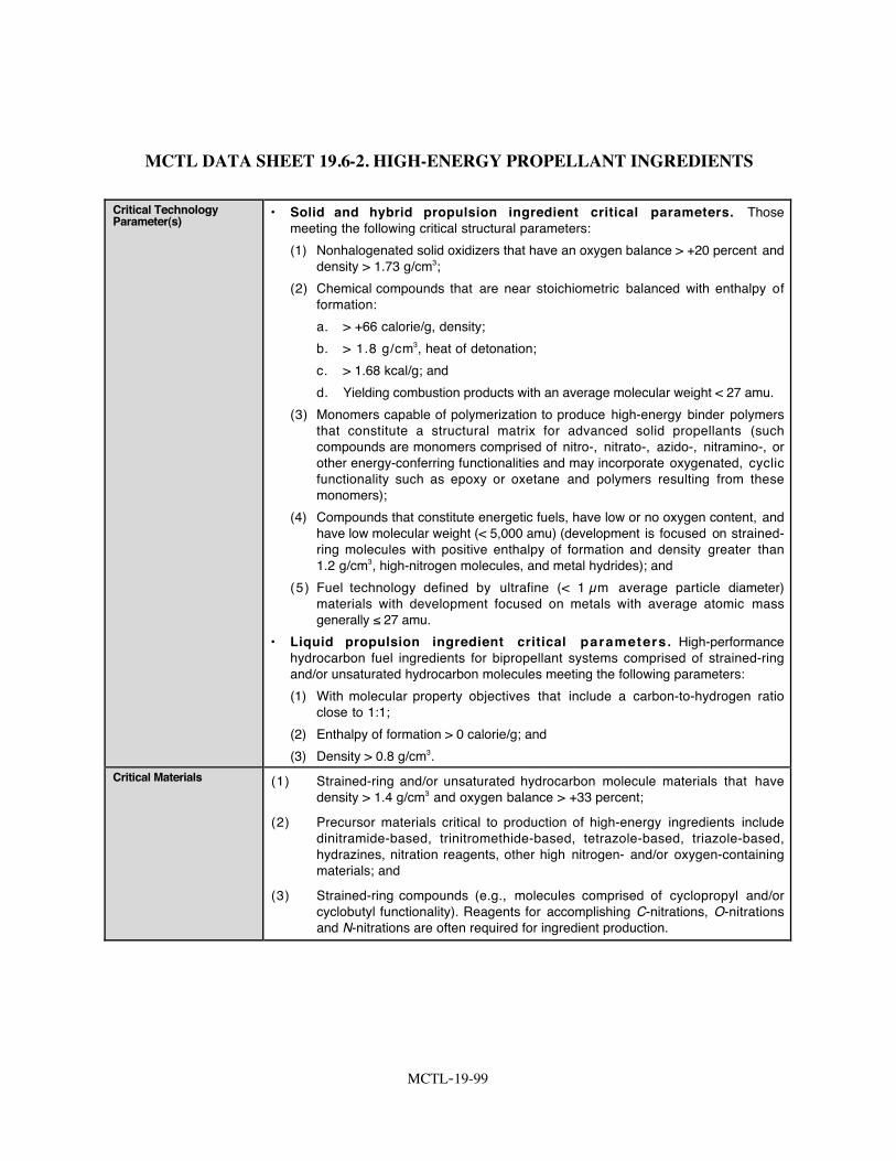
MCTL-19-99
MCTL DATA SHEET 19.6-2. HIGH-ENERGY PROPELLANT INGREDIENTS
Critical TechnologyParameter(s)
• Solid and hybrid propulsion ingredient critical parameters. Thosemeeting the following critical structural parameters:(1) Nonhalogenated solid oxidizers that have an oxygen balance > +20 percent and
density > 1.73 g/cm3;(2) Chemical compounds that are near stoichiometric balanced with enthalpy of
formation:a. > +66 calorie/g, density;b. > 1.8 g/cm3, heat of detonation;c. > 1.68 kcal/g; andd. Yielding combustion products with an average molecular weight < 27 amu.
(3) Monomers capable of polymerization to produce high-energy binder polymersthat constitute a structural matrix for advanced solid propellants (suchcompounds are monomers comprised of nitro-, nitrato-, azido-, nitramino-, orother energy-conferring functionalities and may incorporate oxygenated, cyclicfunctionality such as epoxy or oxetane and polymers resulting from thesemonomers);
(4) Compounds that constitute energetic fuels, have low or no oxygen content, andhave low molecular weight (< 5,000 amu) (development is focused on strained-ring molecules with positive enthalpy of formation and density greater than1.2 g/cm3, high-nitrogen molecules, and metal hydrides); and
(5) Fuel technology defined by ultrafine (< 1 µm average particle diameter)materials with development focused on metals with average atomic massgenerally ≤ 27 amu.
• Liquid propulsion ingredient critical parameters . High-performancehydrocarbon fuel ingredients for bipropellant systems comprised of strained-ringand/or unsaturated hydrocarbon molecules meeting the following parameters:(1) With molecular property objectives that include a carbon-to-hydrogen ratio
close to 1:1;(2) Enthalpy of formation > 0 calorie/g; and(3) Density > 0.8 g/cm3.
Critical Materials (1) Strained-ring and/or unsaturated hydrocarbon molecule materials that havedensity > 1.4 g/cm3 and oxygen balance > +33 percent;
(2) Precursor materials critical to production of high-energy ingredients includedinitramide-based, trinitromethide-based, tetrazole-based, triazole-based,hydrazines, nitration reagents, other high nitrogen- and/or oxygen-containingmaterials; and
(3) Strained-ring compounds (e.g., molecules comprised of cyclopropyl and/orcyclobutyl functionality). Reagents for accomplishing C-nitrations, O-nitrationsand N-nitrations are often required for ingredient production.
MCTL-19-100
Unique Test, Production,Inspection Equipment ( 1 ) Specialized equipment and tests necessary for evaluating ingredient
characteristics include impact sensitivity tester, friction sensitivity tester,electrostatic discharge sensitivity tester, Naval Ordnance Laboratory (NOL)card gap test, and liquid adiabatic compressibility (U-tube) tester.
( 2 ) Note: Some test, production, and inspection equipment for high-energymaterials is common to the explosives industries.
Unique Software Chemical analysis; reaction analysis codes; chemical structure; estimate of chemicaland physical properties of energetic molecules; quality control; performanceprediction.
Major CommercialApplications Many of these materials can be used in producing pharmaceuticals, commercial
explosives and fuels, as well as other commercial products. Satellite launch systems;gun propellants; emergency and auxiliary power units; explosives; vehicular restraintsystems all have direct commercial utility.
Affordability Issues When developed, this technology will increase booster range/payload for same or lowercosts.
Export ControlReferences WA Cat 1; WA ML 8; CCL Cat 1; USML Cat V; MTCR 4.
BACKGROUND
There are two main categories of rocket engines; liquid rockets and solid rockets. In a liquid rocket, thepropellants, the fuel and the oxidizer, are stored separately as liquids and are pumped into the combustion chamber ofthe nozzle where burning occurs. In a solid rocket, the propellants are mixed together and packed into a solidcylinder. There are also hybrid rocket engines which is a combination of these two types. A hybrid rocket burns amixture of solid fuel and liquid or gaseous oxidizer. A hybrid rocket almost matches the high specific impulse ofliquid propellant rocket, and requires only half the number of expensive turbopumps. Hybrid designs typically forgoturbopumps and the liquid oxygen is fed into the combustion chamber by tank pressure.
Under normal temperature conditions, the propellants do not burn; but they will burn when exposed to a sourceof heat provided by an igniter. In a solid rocket motor, once the burning starts, it proceeds until all the propellant isexhausted. With a liquid rocket motor, one can stop the thrust by turning off the flow of propellants. Liquid rocketstend to be heavier and more complex because of the pumps and storage tanks. A solid rocket is much easier to handleand can sit for years before firing.
A liquid propellant rocket burns a mixture of liquid fuel and liquid oxidizer, e.g., hydrogen and oxygen.Hydrogen, like chlorine, destroys the ozone layer. The cheapest and the least toxic fuels are methane, ethane, andpropane. Liquid oxygen is the cheapest and the least toxic oxidizer. Hydrogen peroxide (H2O2) is not as energetic asliquid oxygen and is much more expensive but it can be stored at room temperature and it is a better regenerativecoolant. Diluted hydrogen peroxide can be concentrated up to 90–98 percent by distillation and up to 100 percent bycrystallization. Kerosene fuel and its purified form known as RP-1 can also be stored at room temperature and itburns well with hydrogen peroxide. Unlike kerosene, RP-1 (Rocket Propellant-1) has uniform density, high cokingtemperature, and is free of sulfur.
The overall density of the peroxide/kerosene combination is 1.312 g/cm3, better than overall density of liquidoxygen/methane, which is only 0.828 g/cm3. On the other hand, the liquid oxygen/methane combination has12 percent higher specific impulse and these propellants can be self pressurized, which means that their vaporpressure forces them into the rocket engine. The self-pressurized rocket has simpler design and lower dry weight thana rocket using conventional pressurization system made of a helium tank and a flexible bladder separating the heliumand the propellant. The fuel and oxidizer are mixed and burned in the combustion chamber.

MCTL-19-101
MCTL DATA SHEET 19.6-3. LIQUID ROCKET ENGINES
Critical TechnologyParameter(s) • Specific Impulse (chamber)
Type Isp Chamber Pressure
LOX/LH2 > 400 seconds > 1000 psi,
LOX/Kerosene > 300 seconds > 500 psi,
NTO > 280 seconds > 300 psi,
Nitric Acid > 280 seconds > 300 psi, or
IRFNA/Hydrazine > 280 seconds > 300 psi
• The ratio of delivered Isp (at the exit plane) to Theoretical maximum: > 85% (0.85);
• Delivered Thrust:
First stage or booster > 200 Klbs,
Second or upper stage > 5 Klbs, or
Research engines > 100 lbs
• A Thrust to Weight ratio: T/W > 30; or
• Any liquid rocket engine with one or more of the following features:
• Integrated control and health monitoring systems;
• Monocoque Thrust chamber and nozzle;
• Gimbal angle > 5°;
• Turbomachinery withdelivered horsepower per unit weight > 30 hp/lb;
• Throttling range > 40%; or
• In-flight ignition (Air Start).Critical Materials • Staged combustion: Single Crystal nickel superalloys, narloy Z, hydrogen
embrittlement resistant coatings (gold);
• Full flow staged combustion: Hot oxygen compatible nickel-based superalloys;
• All: copper-chrome-niobium alloys;
• Upper stage: CMCs and refractory metals; and
• Advanced Propellants or propellant additives other than waterUnique Test, Production,Inspection Equipment • Test Equipment: large (> 250 Klb thrust capability) test stands, large propellant
storage systems; cryogenic equipment rated to pressures above 1000 psi;
• Production Equipment: friction Stir welding, electrode position, electro-dischargemachining, ultrafine grained nickel casting, large autoclaves and FSW equipmentfor tankage; and
• Inspection Equipment: None identified.

MCTL-19-102
Unique Software Specialized software for engine design and balancing energy utilization in the engine(power balance), specialized cost analysis codes, combustion modeling, controlsoftware for engine ignition and valve timing, specialized health monitoringarchitecture, CEA (ODE—one dimensional equilibrium), TDK—two-dimensional kinetic,combined thermal fluid structure analysis networks, transient analyses, propellantproperty data bases, Integrated Vehicle Health Monitoring.
Major CommercialApplications Commercial launch vehicle propulsion.
Affordability Issues Limited production runs and quantities, specialized manufacturing processes, andcomplex parts make affordability and issue. Extreme performance requirements limitapplication of affordability technologies. Implementing design for producibilitypractices will improve affordability of next generation systems.
Export ControlReferences WA Cat 1; WA ML 4, 9, 22; CCL Cat 9; USML IV; MTCR 2.
BACKGROUND
Liquid fueled rockets burn a fuel and an oxidizer. The apparent distinction is the liquid state of the fuel and theoxidizer. Several layers of complexity are then added to this rather innocent looking design. More advancedpropulsion systems have been developed, but it will many years before the dominance of the liquid fueled rocket willwane.
There are two main reasons for using liquids. First, chemical rocket engines, the ones using liquid propellantshave the highest specific impulse (Isp). Second, liquid propellant engines are, in some regards, the most flexiblerocket propulsion system available.
Liquid Rocket Engines (LREs) were first reduced to practice by Robert Goddard in the United States starting inthe 1910s as a means of reaching the upper atmosphere for scientific purposes. Robert Goddard’s first turbopumpdriven, Liquid Oxygen (LOx) –gasoline, liquid engine flew in 1941. In Europe, particularly in Germany, launchvehicle enthusiasts began experimenting with LREs in the 1920s also, well before WW II. The first LRE used bythe military was the A4 engine powering the V-2 rocket, used by Germany to bomb England during WW II and firstlaunched in 1942. A mixture of alcohol and water fueled the V-2 with liquid oxygen as the oxidizer. A 1-ton/sec flowrate of propellants generated 56 Kelvin pound of thrust, propelling the V-2 to Mach 5. Most launch vehiclepropulsion systems are based on V-2 technologies to some extent. This system is equivalent in performance andsimilar in technology to Scud type missile systems in operation in the developing world today.
There are two metal tanks holding the fuel and oxidizer respectively. Due to properties of these liquids, they aretypically loaded into their tanks just prior to launch. The separate tanks are necessary, for many liquid fuels igniteand burn upon contact with the oxidizer. Upon a set launching sequence, two valves open allowing the liquid,hitherto blocked, to flow down the pipe-works. If these valves simply opened allowing the liquid propellants to flowinto the combustion chamber at their own leisure, a weak (if any at all) thrust production would incur as well as anunstable flow rate (leading to a unstable thrust rate). Two solutions have been devised to solve this problem: (1) apressurized gas feed and (2) a turbopump feed.
The basics of liquid rocket engine technology can be found at the NASA web site:http://www.grc.nasa.gov/WWW/K-12/airplane/rockth.html .
Liquid rocket engines are used to propel a variety of systems including commercial launch systems, militarysatellite launch systems, and weapons systems. There is no difference between engines used for military andcommercial launch vehicle or satellite propulsion systems while there are significant differences between enginesused for different propulsion applications. Therefore, it is the mission for which the engine is designed, not thetechnology inherent in the engine which determines the parameter space and level of parameters that define militarycriticality for a particular engine. For example, the hydrostatic bearing technology used to improve the performanceof turbopumps for advanced launch vehicle engines is not applicable to the pressure fed engine systems used to
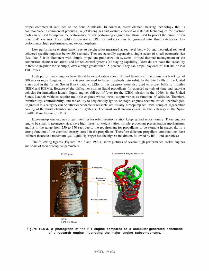
MCTL-19-103
propel commercial satellites or the Scud A missile. In contrast, roller element bearing technology that iscommonplace in commercial products like jet ski engines and vacuum cleaners or materials technologies for machinetools can be used to improve the performance of low performing engines like those used to propel the pump drivenScud B-D variants. To simplify discussions, LRE technologies can be grouped into three categories: lowperformance, high performance, and exo-atmospheric.
Low performance engines have thrust to weight ratios measured at sea level below 30 and theoretical sea leveldelivered specific impulses below 300 seconds. They are generally expendable, single stages of small geometric size(less than 3 ft in diameter) with simple propellant pressurization systems, limited thermal management of thecombustion chamber (ablative), and limited control systems (no staging capability). Most do not have the capabilityto throttle (regulate thrust output) over a range greater than 15 percent. They can propel payloads of 100 lbs or less1500 miles.
High performance engines have thrust to weight ratios above 30 and theoretical maximum sea level Isps of300 secs or more. Engines in this category are used to launch payloads into orbit. In the late 1950s in the UnitedStates and in the former Soviet Block nations, LREs in this category were also used to propel ballistic missiles(IRBM and ICBMs). Because of the difficulties storing liquid propellants for extended periods of time and readyingvehicles for immediate launch, liquid engines fell out of favor for the ICBM mission in the 1960s in the UnitedStates. Launch vehicles require multiple engines whose thrust output varies as function of altitude. Therefore,throttlability, controllability, and the ability to sequentially ignite, or stage, engines become critical technologies.Engines in this category can be either expendable or reusable, are usually turbopump fed, with complex regenerativecooling of the thrust chamber and control systems. The most well known engine in this category is the SpaceShuttle Main Engine (SSME).
Exo-atmospheric engines propel satellites for orbit insertion, station keeping, and repositioning. These enginestend to be small in geometric size, have high thrust to weight ratios, simple propellant pressurization mechanisms,and Isps in the range from 250 to 350 sec, due to the requirement for propellants to be storable in space. (Isp is astrong function of the chemical energy stored in the propellants. Therefore different propellant combinations havedifferent theoretical maximum Isps. Liquid Hydrogen has the highest maximum, followed by RP-1 and storables.)
The following figures (Figures 19.6-3 and 19.6-4) show pictures of several high performance rocket enginesand some of their descriptive parameters.
Figure 19.6-3. A photograph of the F-1 engine compared to a computer-generated schematicof a research engine illustrating the major engine subcomponents.
Nozzle / Exit Cone
Turbopump
CombustionChamber236 in
147 in1,500 Klb Thrust
F-1 Engine Experimental Engine Illustration

MCTL-19-104
Engine manufacturers use a wide range of terminology to describe LREs. Some of the terminology isdescriptors of the engine configuration and others are quantitative parameters of engine performance.
Thrust: Thrust is the force generated by the engine. It is generally measure in pounds force (or Kelvin pound) inthe United States and metric tones or KiloNewtons (KN) elsewhere. The actual thrust quantity has more to do withthe mission the engine is performing and its configuration in a vehicle than to its level of technology or performancecharacteristics. A single first stage booster engine might generate one million pounds of thrust, while a gang ofsmaller LREs in the 200 Kelvin pound thrust class might also be used of a first stage booster mission. Upper stageengines tend to be in the 20 to 80 Kelvin pound thrust class, while orbital maneuvering and vernier engines canproduce very small, 10 lb, thrusts.
Figure 19.6-4. Courtesy of the NASA web site at: http:/ /www.grc.nasa.gov/WWW/K- 12/airplane/rockth.html
Geometric size generally related to thrust class. Large booster engines can be 20 ft tall with nozzle exit planesover 10 ft in diameter. Most of the engine’s size is taken up by the nozzle/exit cone. Exo-atmospheric thrusters canfit in a shoe box.
Thrust to weight ratio, T/W: The ratio of the force generated by the engine at sea level to weight of the engineincluding the nozzle/exit cone, but excluding any mounting hardware. A direct measure of the structural efficiency ofa rocket engine, T/W indicates the sophistication of the engine machinery. High performance engines have T/W >30/1. Varies greatly with Isp of the propellant and the area ratio of the nozzle.http://www.spaceworks.aero/downloads/SEI_TW_Trends_022801.pdf
Specific Impulse, Isp or Is: The thrust of the engine divided by the weight flow rate of propellants. Measured inlbs/lbs/sec or simply, secs. A function of the chemical energy stored in the propellants, pressure in the combustionchamber, area ratio of the nozzle/exit con, and the efficiency of the engine. Directly related to the final velocity of thevehicle, and therefore the range and payload capability of the vehicle. Engines with ratios of delivered Isp (what isactually achieved by the functioning engine) to theoretical maximum (predicted from chemical equilibrium) greaterthan 85 are high performance engines.
Mixture ratio, O/F: The ratio of oxidizer to fuel burned in the combustion chamber. Stochoimetric (Rationecessary to fully react all the fuel with all the oxidizer.) ratio varies with propellant combination. Ratio actuallyemployed by an engine is a function of the engine design.
Propellant type: Cryogenic (LOx/LH2), hydrocarbon (LOx/RP-1), storable (NTO/MMH). Propellantcombination sets maximum theoretical Isp, range of useful mixture ratios, and implies certain engine configurations.Different propellant types are optimal for different missions.

MCTL-19-105
Reusability: While aircraft engine lives are measured in the thousands of operational flight hours, generalrocket engine single mission lives are less than 12 minutes. Whether an engine is reusable or expendable definesassumptions made during the design process.
Performance data for some of the commonly used rocket engines is shown in Table 19.6-1. This data is takenfrom the following web site: http://dutlsisa.lr.tudelft.nl/Propulsion/Data/Rocket_motor_data.htm#Large_bipropellant
Table 19.6-1. Performance data of typical large liquid thermo-chemical rocket engines
SSME HM60 LE-7 RS-68 RD-170 RD-180
Propellants LOX/LH2
LOX/LH2
LOX/LH2
LOX/LH2
LOX/Kerosene
LOX/Kerosene
Engine cycle SC GG SC GG SC SC
Vacuum thrust (kN) 2090 1075 1078 3310 7910 4152
Specific impulse (s) 455,2 430 446 410 336-337 338
Overall mixture ratio;O/F (-)
6,0 5,3 6,0 NA 2,63 2,72
Propellant density(kg/m3)
333 346 333 NA 1008 1011
Length (m) 4,24 3,00 3,40 5,18 4,0 3,8
Total dry mass (kg) 3170 1300 1714 6597 9750 5393
Mission duty cycle (s) 480 600 346 NA 140–150 150
Thrust/weight ratio (-) 67 84 64 51 83 79
Throttle capability (%) 67–109 NA None 60–100 56–100 50–100
Operational use (year) 1981 1996 1994 2001? 1985 1999?
Reliability 0,999 0,9927 0,9935 NA 0,999 NA
Engine cycle: defined as the path the propellants take to the combustion chamber and what source is used topush, or pull the propellants from their tanks. Engine cycle implies the configuration, arrangement, and specificenvironments of engine components. Different cycles are optimum for different applications. Closed cycle pump-fedengines tend to be higher performance than open cycle or pressure fed engines. Categories of open (turbine drive gasdumped overboard) or closed (turbine drive gas fed into the combustion chamber): expander (uses energy picked up bythe propellant from cooling the combustion chamber to drive the turbines), gas generator (uses hot gas from anauxiliary reaction to drive the turbine), pressure-fed (no turbopump, tank pressure alone feeds the combustionchamber), staged combustion (uses a small combustion device to create drive gas for the turbine from thepropellants), full flow (uses two combustion devices, one fuel-rich to drive the fuel pump turbine and the otheroxygen-rich to rich the oxidizer turbine). Combinations and specifications of these cycles are possible.

MCTL-19-106
MCTL DATA SHEET 19.6-4. LIQUID ROCKET ENGINES COMBUSTION CHAMBERDEVICES
Critical TechnologyParameter(s) Any liquid rocket engine Combustion Chamber device that meets any of the following
criteria:
• Pressure ≥ 2500 psia;
• PV/W (Pressure times internal Volume divided by weight) < 8 Kpsi in3/lbs;
• Maximum Temperature ≥1500 °F;
• Heat Flux > 10 btu/in2 per second; or
• Any Specially Designed Thermal Management control system, components ortechniques for Transpiration, such as:
- Regenerative (with either fuel or oxidizer), film coolant;
- Radiative cooling; or
- Thermal barrier coatings.Critical Materials • Narloy Z, copper-chrome-niobium alloys.
• Titanium alloys for Hydrcarbon engines.
• Polymer Matrix Composites overcoats and stiffners.
• Ceramic matrix composites.Unique Test, Production,Inspection Equipment Test: Operating chamber pressure(s) exceeding 2500 psia.
Production:
• Friction Stir Welding;
• Electrodeposition;
• Electro-discharge machining; and
• Filament winding and tape placement.
Inspection: UT, CT, real time X-ray, Flash Thermography and Dye-penetrant are allcritical techniques.
Unique Software Specialized software for cooling design and conjugate heat transfer, cost analysiscodes, Combustion modeling, Injector Design, control software for engine ignition andvalve timing, and health monitoring architecture.
Major CommercialApplications Commercial Launch Vehicle propulsion. Commercial industry and NASA mission
requirements drive engine reusability requirements.Affordability Issues Limited production runs and quantities, specialized manufacturing processes, and
complex parts make affordability an issue. Extreme performance requirements limitapplication of many more affordable technologies. Implementing design forproduceability practices will improve affordability of next generation systems orproduction runs.
Export ControlReferences WA Cat 9; WA ML 4; CCL Cat 9; USML Cat IV; MTCR 3.

MCTL-19-107
BACKGROUND
The arrangement of components in a liquid engine leads to two fundamental categories of liquid rocket engine(LRE) subsystems: Propellant Management Devices, (PMDs) and Combustion and Energy Conversion Devices(C&ECD). For C&ECD, the technologies generally concern achieving and surviving combustion and combustionproducts in a high temperature and high heat flux environment. C&ECD can be subdivided into the maincombustion chamber (MCC),* turbine powering systems, main injector and igniter.
*Please note, in the U.S. nomenclature, MCC includes the throat plane. An LRE can employ technology toallow the MCC throat plane and Nozzle to be a monolithic unit.
Main Combustion Chamber (MCC)
The energy from a high-pressure combustion reaction of propellant chemicals, usually a fuel and an oxidizingchemical, permits the heating of reaction product gases to very high temperature (4500 to 7500 °F). These gasessubsequently are expanded in the nozzle and accelerated to high velocities (6000 to 14,000 ft/sec). In the thrustchamber the propellants react to form hot gases, which in turn are accelerated and ejected at a high velocity through asupersonic nozzle, thereby imparting momentum to the system.
“The thrust of a rocket is the reaction experienced by its structure due to the ejection ofhigh-velocity matter--the same phenomenon that makes a gun recoil.” (Design of Liquid-PropellantRocket Engines, Vol 147, AIAA, 1992.)
The main purpose of the MCC is to contain the propellants (providing a volume for combustion) in a mannerto allow the “orderly” conversion of their chemical potential energy into kinetic energy (hot, high pressure gas).Thrust results from acceleration and ejection of the gas.
MCC Performance Measures
• Heat flux.
• Thrust to Weight.
• Component Weight.
• Component Life (# of cycles).
• Maximum Chamber Pressure.
• Maximum Cooling Circuit Pressure (REGEN).
MCC Chamber Thermal Management Techniques
• Ablative
- Process using a combination of melting, vaporization, and chemical changes to dissipate heat. Theablative material is a good insulator and keeps heat from being transferred to the outer structure.
- Materials are essentially reinforced plastics.
- Reinforcing fibers can be either organic or inorganic.
- Fibers often have different geometric arrangements, as well as different resins or plastic fillersdepending upon requirements.
- Chambers are created by bonding together layers, or plys. Proper bonding is critical.
- Not typically reusable.

MCTL-19-108
• Regenerative
- Utilizes one or possibly both propellants fed through cooling passages in the chamber wall for cooling,before being injected into the combustion chamber through the injector.
- Design characteristics include:
— Thin hot gas wall (HGW) to reduce thermal stress;
— Material with high thermal conductivity;
— Formed tubes; and
— Milled channels.
• Dump Cooling—Similar to regenerative cooling except coolant is ‘dumped’ into the main combustiongases and not routed back through the main injection system.
• Radiation
- Provides cooling by radiating heat directly from the chamber to its surroundings.
- Common technique for small thrusters, gas generators, or the nozzle extension, which may be attachedto a regeneratively cooled chamber.
- Chamber materials include:
— Inconel for temperatures up to 2050 °F;
— Coated refractory materials for temperatures up to 2050 °F;
— Columbium, niobium, rhenium, platinum, molybdenum;
— Carbon-reinforced-carbons have potential beyond 5000 °F.
- Surrounding components may have to be shielded from the high temperature.
• Film
- Process in which a relatively cool, thin fluid film covers and protects exposed wall surfaces fromexcessive heat flux.
- Inject fluid parallel to combustion gases at injector face or at throat.
- A related technique, transpiration cooling, introduces coolant in small quantities through a largenumber of small orifices located in the hottest regions.
• MR Basis
- Process in which the main injector mixture ratio of propellants is varied to give a lower combustiontemperature on the hot gas wall.
MCC Combustion Instability Prevention Devices
These devices are treated in more detail in the injector MCTL document, but for completeness examples arelisted below.
• Acoustic design.
• Cavities.
• Baffles.
• Injector MR biasing.

MCTL-19-109
Turbine Powering Systems (Preburners/Gas Generators)
Preburner/Gas Generator provides ‘Drive Gas’ to turbopump turbine at the temperature required to providedesign energy transfer for the pump rotor assembly. The term “preburner” is typically used in staged combustionengines where the oxidizer or fuel rich preburner drive gas is routed to the main injector for enhanced engineperformance. The term “gas generator” is typically used when the drive gas is exhausted to the atmosphere or to thenozzle to enhance performance.
• Thermal Issues (similar to MCC)
- Do Materials of Construction Maintain Strength Required to Meet Design Requirements.
- Cooling of Chamber Due to Hot Spots.
• Design Preburner Combustion so that Wall Temperature Meets Component Life Requirement (MR Bias).
• Prevention of Propellant/Hardware Incompatibility.
• Ensure proper purging to ensure proper combustion and ignition sequencing.
• Design for uniform exhaust temperature to enhance turbopump turbine blade life.
Igniter
The igniter is required for starting the combustion process. Igniter issues for C&ECD are treated in more detailin the injector MCTL Document 19.6-7 but for completeness examples are listed below.
• Torch system using engine propellants ignited with a spark plug and an exciter system.
• Pyrophorics are highly reliable ignition sources in the presence of an oxidizer.
• Continuous Wave Ignition ignite propellants with microwave detonations.
• Laser ignition ignites propellants with laser beams carried by fiber optic cables.
• Hypergolic propellants ignite on contact with each other, so they do not need an igniter.
SSME Powerhead. Main Injector, MCC, Fuel and Oxidizer Pumps and Pre-burners
Manufacturer: RocketdyneApplication: Space ShuttlePropellants: LO2/LH2Engine Cycle: Fuel Rich Staged Combustion (FRSC)Thrust: 400,000 lbfChamber Pressure: 3000 psi

MCTL-19-110
MCTL DATA SHEET 19.6-5. LIQUID ROCKET ENGINE NOZZLE (EXIT CONE)TECHNOLOGY
Critical TechnologyParameter(s) Any nozzle/exit cone that meets any of the following criteria. The temperature
extremes seen by these nozzles distinguishes them from commercial nozzles for otherapplications:
• Temperature environments > 3000 °F;
• Area ratio: AR > 15;
• Monocoque designs with Main Combustion Chamber;
• Defined starting Area ratio < 6;
• Regenerative cooling, ablation < 0.5 mils/sec ablation rate;
• Thermal barrier coating/ thermal management schemes for extreme temperatures> 3000 °F; or
• Complex Nozzle Designs/Contours—Rao (parabola shaped), DeLaval, or < 80%bell designs, dual bell and altitude compensating designs (including extendableexit cones).
Critical Materials Inco 718, 347 CRES, Thermal Barrier coatings, Cu-Cr-Nb alloys, SiC/SiC, C/SiC, Si3N4;Refractory metals: Rhenium, iridium, tungsten, tungsten carbide.
Unique Test, Production,Inspection Equipment Production: Large Braise furnaces, micro-welding capabilities for repair, large
infiltration and CVD furnaces for Ceramic Matrix Composites (CMC) materials.Unique Software Design tools, many based on historical data, tools for creating efficient contours like
Rao method calculations.Major CommercialApplications Commercial launch vehicle systems.
Affordability Issues Size, reparability, and limited market make affordability an issue, particularly for CMCand Graphite based structures.
Export ControlReferences
WA Cat 9; WA ML 4; CCL Cat 9; USML Cat IV; MTCR 3.
BACKGROUND
The nozzle is the component of a rocket or air-breathing engine that produces thrust. This is accomplished byconverting the thermal energy of the hot chamber gases into kinetic energy and directing that energy along thenozzle's axis, as illustrated in Figure 19.6-5. Specific liquid nozzle geometries can be Parabolic, Conical, Bell, orFree-Form. The nozzle or exit cone of a liquid rocket engine directs and contains expanding combustion gases tocreate thrust efficiently. Ideally, a rocket would like each molecule of expanding combustion gas to reach ambientpressure with a velocity vector exactly opposite the vehicle’s trajectory. Causing the expansion to happen in thisway creates the shape of the exit cone structure. Cone, bell, and parabola shapes known as Rao contours are commonshapes for liquid rocket engine nozzles. A de Laval nozzle (or convergent-divergent nozzle, CD nozzle or con-dinozzle) is a tube that is pinched in the middle, making an hourglass-shape. It is used as a means of accelerating theflow of a gas passing through it. It is widely used in some types of steam turbine and is an essential part of themodern rocket engine.
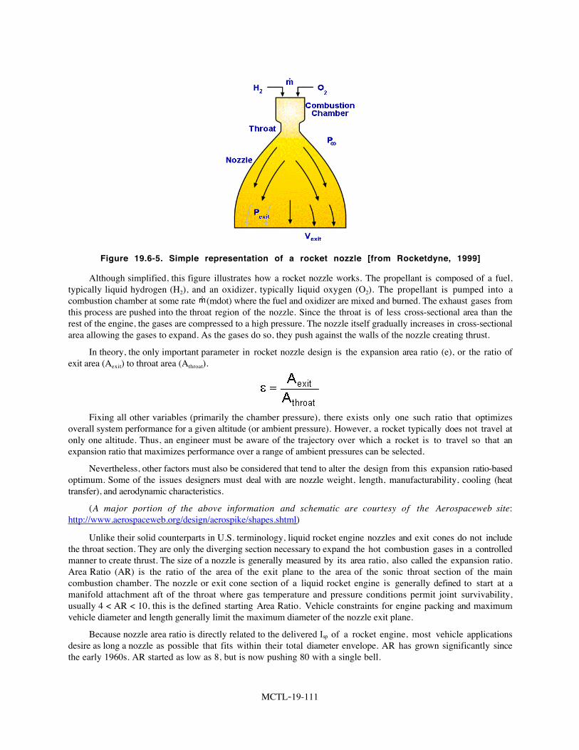
MCTL-19-111
Figure 19.6-5. Simple representation of a rocket nozzle [from Rocketdyne, 1999]
Although simplified, this figure illustrates how a rocket nozzle works. The propellant is composed of a fuel,typically liquid hydrogen (H2), and an oxidizer, typically liquid oxygen (O2). The propellant is pumped into acombustion chamber at some rate (mdot) where the fuel and oxidizer are mixed and burned. The exhaust gases fromthis process are pushed into the throat region of the nozzle. Since the throat is of less cross-sectional area than therest of the engine, the gases are compressed to a high pressure. The nozzle itself gradually increases in cross-sectionalarea allowing the gases to expand. As the gases do so, they push against the walls of the nozzle creating thrust.
In theory, the only important parameter in rocket nozzle design is the expansion area ratio (e), or the ratio ofexit area (Aexit) to throat area (Athroat).
Fixing all other variables (primarily the chamber pressure), there exists only one such ratio that optimizesoverall system performance for a given altitude (or ambient pressure). However, a rocket typically does not travel atonly one altitude. Thus, an engineer must be aware of the trajectory over which a rocket is to travel so that anexpansion ratio that maximizes performance over a range of ambient pressures can be selected.
Nevertheless, other factors must also be considered that tend to alter the design from this expansion ratio-basedoptimum. Some of the issues designers must deal with are nozzle weight, length, manufacturability, cooling (heattransfer), and aerodynamic characteristics.
(A major portion of the above information and schematic are courtesy of the Aerospaceweb site:http://www.aerospaceweb.org/design/aerospike/shapes.shtml )
Unlike their solid counterparts in U.S. terminology, liquid rocket engine nozzles and exit cones do not includethe throat section. They are only the diverging section necessary to expand the hot combustion gases in a controlledmanner to create thrust. The size of a nozzle is generally measured by its area ratio, also called the expansion ratio.Area Ratio (AR) is the ratio of the area of the exit plane to the area of the sonic throat section of the maincombustion chamber. The nozzle or exit cone section of a liquid rocket engine is generally defined to start at amanifold attachment aft of the throat where gas temperature and pressure conditions permit joint survivability,usually 4 < AR < 10, this is the defined starting Area Ratio. Vehicle constraints for engine packing and maximumvehicle diameter and length generally limit the maximum diameter of the nozzle exit plane.
Because nozzle area ratio is directly related to the delivered Isp of a rocket engine, most vehicle applicationsdesire as long a nozzle as possible that fits within their total diameter envelope. AR has grown significantly sincethe early 1960s. AR started as low as 8, but is now pushing 80 with a single bell.

MCTL-19-112
Because of size and uniqueness of shape, there are no commercial applications for liquid rocket engine nozzlesand exit cones outside of the commercial launch industry (see Figure 19.6-6).
Two factors drive nozzle/exit cone design: thermal management and structural survivability. The combustiongas temperature expanding through the nozzle can exceed 6000 °F of mostly steam. Because of the high temperature,high velocities, and two-phase flow, some mechanism must exist to protect the nozzle material from erosion andablation during engine operation. Methods of thermal management are similar to those employed in the maincombustion chamber. Regenerative cooling, ablation, fluid film or dump cooling, and thermal barrier coatingsystems are mechanisms for guaranteeing survivability of nozzle structures. Nozzle structures must also react to thethrust loads, gimballing loads, and severe vibrations, both acoustic and mechanical. Careful structural designminimizes weight of these shell structures while reacting to loads and surviving severe fatigue environments.Nozzles can be expendable or reusable, depending on the application.
Figure 19.6-6. Size comparison of optimal cone, bell, and radial nozzles for a given set ofconditions. (Source: http://www.aerospaceweb.org/design/aerospike/shapes.shtml . )
Control of the thrust vector, the speed and direction of the exhaust gases to control the vehicle’s trajectory, isaccomplished in many ways with liquid rocket engines. Some vehicles use small engines in the nose of the vehicleto control roll and yaw. These are separate vernier engines that do not affect the performance of the main thrustproducing engine(s). In most Liquid rocket engine systems, the engine and thrust chamber themselves are gimbaledso the entire engine and nozzle as a unit can be rotated off the main vehicle axis by several degrees. This ability torotate implies significant flexibility in the lines, ducts, and power cables feeding the engine. Unlike their solid motorcounterparts, few liquid rocket engines gimbal only the thrust chamber or nozzle assemblies. While it is possible torotate only the nozzle assembly, the structure required to duct and seal against the hot combustion gasses tend to becomplicated and heavy, reducing the overall performance of the system. In early rocket systems mechanical vanes inthe nozzle redirected the exhaust plume. Due to survivability of the vanes, their weight, and complexity, the vaneconcepts for thrust vector control (TVC) has also fallen out of favor. Secondary injection of fluids into the thrust

MCTL-19-113
chamber or along the nozzle hot gas wall has also been proven effective for controlling the direction of the exhaustwithin a range of angles.
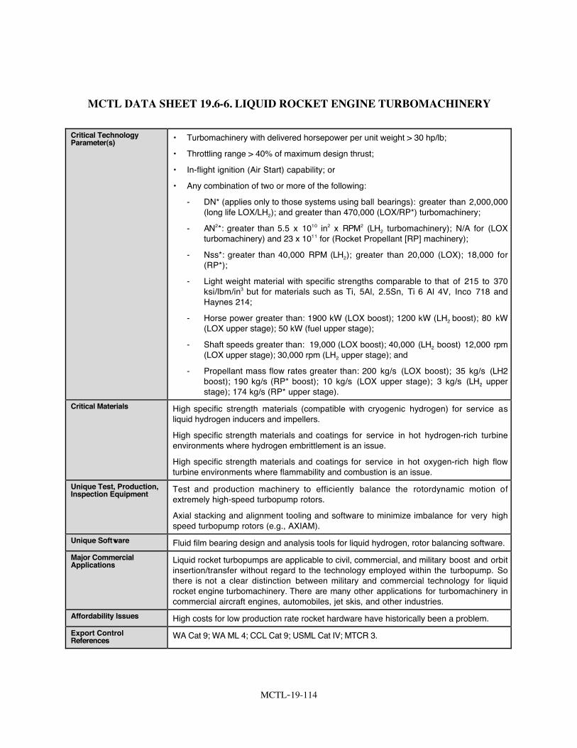
MCTL-19-114
MCTL DATA SHEET 19.6-6. LIQUID ROCKET ENGINE TURBOMACHINERY
Critical TechnologyParameter(s) • Turbomachinery with delivered horsepower per unit weight > 30 hp/lb;
• Throttling range > 40% of maximum design thrust;
• In-flight ignition (Air Start) capability; or
• Any combination of two or more of the following:
- DN* (applies only to those systems using ball bearings): greater than 2,000,000(long life LOX/LH2); and greater than 470,000 (LOX/RP*) turbomachinery;
- AN2*: greater than 5.5 x 10¹⁰ in2 x RPM2 (LH2 turbomachinery); N/A for (LOXturbomachinery) and 23 x 1011 for (Rocket Propellant [RP] machinery);
- Nss*: greater than 40,000 RPM (LH2); greater than 20,000 (LOX); 18,000 for(RP*);
- Light weight material with specific strengths comparable to that of 215 to 370ksi/lbm/in3 but for materials such as Ti, 5Al, 2.5Sn, Ti 6 Al 4V, Inco 718 andHaynes 214;
- Horse power greater than: 1900 kW (LOX boost); 1200 kW (LH2 boost); 80 kW(LOX upper stage); 50 kW (fuel upper stage);
- Shaft speeds greater than: 19,000 (LOX boost); 40,000 (LH2 boost) 12,000 rpm(LOX upper stage); 30,000 rpm (LH2 upper stage); and
- Propellant mass flow rates greater than: 200 kg/s (LOX boost); 35 kg/s (LH2boost); 190 kg/s (RP* boost); 10 kg/s (LOX upper stage); 3 kg/s (LH2 upperstage); 174 kg/s (RP* upper stage).
Critical Materials High specific strength materials (compatible with cryogenic hydrogen) for service asliquid hydrogen inducers and impellers.
High specific strength materials and coatings for service in hot hydrogen-rich turbineenvironments where hydrogen embrittlement is an issue.
High specific strength materials and coatings for service in hot oxygen-rich high flowturbine environments where flammability and combustion is an issue.
Unique Test, Production,Inspection Equipment Test and production machinery to efficiently balance the rotordynamic motion of
extremely high-speed turbopump rotors.
Axial stacking and alignment tooling and software to minimize imbalance for very highspeed turbopump rotors (e.g., AXIAM).
Unique Software Fluid film bearing design and analysis tools for liquid hydrogen, rotor balancing software.Major CommercialApplications Liquid rocket turbopumps are applicable to civil, commercial, and military boost and orbit
insertion/transfer without regard to the technology employed within the turbopump. Sothere is not a clear distinction between military and commercial technology for liquidrocket engine turbomachinery. There are many other applications for turbomachinery incommercial aircraft engines, automobiles, jet skis, and other industries.
Affordability Issues High costs for low production rate rocket hardware have historically been a problem.Export ControlReferences WA Cat 9; WA ML 4; CCL Cat 9; USML Cat IV; MTCR 3.

MCTL-19-115
BACKGROUND
Liquid rocket engines typically require devices to facilitate the rapid and reliable transfer of large volumes ofpropellant (cryogenic and/or room-temperature storable oxidizers and fuels) from rocket storage vessels to thecombustion chamber(s). Rocket engines can be separated into two different categories: pressure-fed and pump-fed.Pressure-fed engines use positive expulsion devices such as high-pressure tanks to force the propellants into thecombustion chamber under high pressure. The weight of these high-pressure tanks is a direct function of the pressuredesired in the combustion chamber. Pressure-fed engines do not use turbomachinery. Pump-fed engines use thelowest tank pressures (and consequently lightest tank weight possible) and utilize a turbopump to provide the high-pressure propellants to the combustion chamber.
For small increases in velocity, such as for satellite orbit changes, only small amounts of thrust andpropellants are required. Because pressure-fed systems are small and typically low weight, they are adequate for thismission. For large changes in velocity, such as for launch from the surface of the Earth to orbit, large amounts ofthrust and propellants are required. Under these circumstances, pressure-fed systems would be large and heavy becausethe propellant tanks must be strong enough to contain large amounts of high-pressure rocket propellant.Turbopump-fed systems can reduce overall launch vehicle weight when, for a given payload weight andcorresponding rocket engine chamber pressure and thrust, the weight of the pressure-fed tanks is greater than the sumof the weight of the turbopumps plus the lower pressure propellant tanks. The vast majority of launch vehicles todayutilize turbopumps rather than pressure-fed tankage because of superior performance for boost and orbitalinsertion/transfer applications. Simply put, for large payloads, turbopump-fed rocket engines allow for asubstantially smaller, lighter weight and lower cost launch vehicle for orbital insertion/transfer missions as comparedto pressure-fed launch vehicles.
The military uses highly efficient turbomachinery (turbines, centrifugal as well as axial pumps, and theirassociated subcomponents) to achieve effective mass transfer and thermal management of the LRE for rocket ormissile boost and orbit insertion/transfer missions. Turbomachinery pumps propellant to high pressures (> 3000psia) through the engine and can also support engine start transients from 1 to 5 seconds to generate up to 2 millionpounds of thrust. They must also be capable of supporting off-on (restart) as well as provide a wide range ofthrottability (> 40 percent of maximum design thrust) in order to be of significant military criticality.Turbomachinery used in LREs are capable of rotating at speeds in excess of 28,000 rpm and render practical theability to inject a payload weighing over 42,000 lbm into Low Earth Orbit or a payload of over 12,000 lbm intoGeoSynchronous Orbit.
Sample combinations of two or more critical specifications include:
• High AN2 plus light weight, high specific strength material for rocket propulsion;
• High DN rolling element bearings for rocket turbomachinery application or hydrostatic or magneticbearings plus high strength, light weight case material;
• High Nss, high mass or volume flow plus light weight, high specific strength material plus centrifugalpump design;
• High NPSH plus light weight, high specific strength material, plus high AN2;
• High flow rate turbomachinery plus high specific strength material plus rotating-to-stationary component(e.g., case-to-blade) machine tolerances greater than 1/10 of a mil (mil—1/1000th inch);
• High horse power turbomachinery plus high specific strength material; and
• High horse power turbomachinery plus high specific strength material plus throttability greater than60 percent of maximum design thrust.
Nss—“Suction Specific Speed”: a measure of inducer suction performance.
NPSH—“Critical Net Positive Suction Head”: the difference between the propellant inlet total pressure headand the propellant vapor pressure.
MCTL-19-116
DN—“Bearing Dynamic Number”: a function of specific bearing type which describes expected rolling elementbearing life.
AN2—“Turbine Annulus Area times Speed Squared”: a function of turbine material blade specific strength,stress and other properties at turbine operating temperatures and rotation speed. This measures structural efficiency atspeed.
RP—“Rocket Propellant –1”: a purified for of kerosene of uniform density, high coking temperature, and freeof sulfer.
Pump head rise, pump developed head; pump discharge pressure: the difference between pump-discharge totalhead and pump suction head. “Head” is the height of a column of liquid with equivalent pressure at its bottom is anindication of the pumping capability and is a function of the combustion chamber pressure and hydraulic lossesdownstream of the pump.
Throttability range greater than 40 percent of maximum design thrust to over 105 percent of maximum designthrust in increments smaller than 10 percent/step: ability to decelerate or accelerate the turbomachinery on command.

MCTL-19-117
MCTL DATA SHEET 19.6-7. LIQUID ROCKET ENGINE INJECTORS
Critical TechnologyParameter(s) Three independent parameters define the militarily critical parameters of liquid rocket
engine injectors. They are Thrust Generation, Efficiency, and Specially designedcomputer codes and algorithms.
• Thrust Generation > 5000 lbf (at any efficiency);
• C* efficiency > 90% of the theoretical limit for any thrust class of single or multipleelements; or
• Computational environment prediction codes and algorithms.
Note: The theoretical limit can be calculated from one-dimensional chemical equilibriumor two-dimensional chemical kinetic equations.
Critical Materials Regimesh.Unique Test, Production,Inspection Equipment Unique test facilities are needed for injector development. These include test stands
capable of providing high-pressure (greater than 500 psi) liquid or gaseous rocketpropellants. High pressure (greater than 1000 psi) instrumented water spray facilitiesthat have flow visualization tools such as high-speed cameras, laser velocitymeasurement, and other flow visualization tools.
Production: Chemical etching of metals, EDM, small diameter laser drilling and othertechnology that produces long, small holes (0.01–0.25 in diameter) (holes with length todiameter ratios greater than 4 with tolerances less than 0.08% of hole diameter).
Cleaning and inspecting: LOX cleaning equipment and chemicals. Unique Software Fluid Dynamic codes that have the following: Mixing, spray, atomization, vaporization,
turbulence, combustion flow, finite rate chemistry, ignition and acoustics.
Design: The design processes uses finite element codes that have integratedstructural and thermal analysis.
Data Bases: Liquid propellant fluid properties including transport properties, physicalproperties over wide thermal range (-200 °F > temperatures > 2500 °F for cryogenicsand < 500 °F for non-cryogenic propellants, and pressures > 1000 psi) (not justStandard Temp & Pres).
Major CommercialApplications None for Oxidizer and Fuel injector: Notable similar commercial products are Air and
Fuel Injectors for Internal Combustion Engines (examples: gas turbines, auto, anddiesel).
Affordability Issues Rocket injector development is unaffordable. While the cost to fabricate many injectorsis very low, the cost to develop, integrate, and test injectors in a system is the barrier.
Export ControlReferences WA Cat 1 and 9; WA ML 4, 9, and 22; CCL Cat 1, 2B and 9; USML Cat IV; MTCR 3.
BACKGROUND
The injectors for Liquid Rocket Engines (LREs) can be classified in either the propellant management device orcombustion and energy conversion device taxonomy. They are also considered flow control devices, mixing plates, orpropellant (or fuel) metering devices. The purpose of the injector is to both meter the flow of propellants into thecombustion device (flow/time) and control the location and momentum of fuel entry to create a uniform mixture forcombustion, while keeping the fuel and oxidizer separate until combustion. Due to the structural efficiency of thecylindrical shape for the combustion chamber, injectors for LREs tend to be circular with diameters ranging fromseveral inches to several feet. While they appear to be fairly simple devices of thick round plates with many small
MCTL-19-118
diameter tubes and holes (hole diameters from 0.01 in to 0.25 inch), injectors are hydro-dynamically complex.Ensuring injectors can precisely control liquid quantities over a wide range of throttle ratios (flow rates from40–110 percent of engine rated maximum), start, and shutdown conditions while maintaining a stable combustionenvironment implies complex and precise internal features. Injectors range in size from several inches diameter for1000 lb thrust research engines to 18 inches for the SSME (475-Kelvin pound thrust class). They must survivecombustion environment by cooling their structure and create flame front stand off by incorporating features tomaintain stable combustion.
Design has not matured sufficiently for there to be a single configuration for a given application. Much ofinjector design is art and empirically based. Significant vocabulary exists to describe details of the injector design.The state of propellants exiting injector face (gas-gas, gas-liquid, liquid-liquid), orifice pattern (co-axial, pentad, etc.),and flow stream characteristics (impinging, swirl, etc.) describe the injector and imply specific features. However,this vocabulary is not critical in determining the criticality of a liquid rocket engine injector to military applications.
Injectors are used in every other device that uses liquid fuel and air; i.e., automotive internal combustionengines, jet engines, stationary power generation turbines, chemical processes, and furnaces for every purpose fromresidential heating to steel making. What makes rocket injectors different is the injection of both a strong oxidizerand fuel. Furnaces, autos, jets, etc. use air as their oxidizer which is typically 70-percent nitrogen diluents. Due tothe lack of nitrogen diluents the operating conditions of rocket injectors are more severe. The thermal environment ina rocket engine combustor can be ten times worse than a jet engine, requiring intricate cooling and extremedesign/manufacturing precision to create the cooling passages. The operating conditions for a rocket injector are,therefore, very limited, in terms of throttling, range of oxidizer to fuel quantity ratio, and start/stop. In addition,special care is taken to clean and protect the injector itself from contaminates as well as contaminants in thepropellants.
In addition, there are many technologies that go into making injector efficiency—specialized drilling of theorifices for smooth, precision, injection pattern, and mixing efficiency. However, it is more art than science in mostcases. Computational environment prediction codes and algorithms are uniquely enabling and considered a criticaltechnology area. Many companies have proprietary component designs such as for platelet injectors, posted injectors,drilled orifice plates, regimesh, and foam injectors. However, these technologies are not published and not coveredhere do to limited known specifications.
MCTL-19-119
MCTL DATA SHEET 19.6-8. SOLID ROCKET ENGINE NOZZLE TECHNOLOGY
Critical TechnologyParameter(s)
For Space System Rocket Engine* Nozzles:• Thrust > 45 kN (200,160 lbf);• Max erosion rate < 0.075 mm/sec (< 0.00295 in/sec = 2.95 mils/sec);• Carbon-carbon densities > 1.94 g/cc; and• Production times < 3 months to form carbon-carbon densities to > 1.7 g/cc.*Note: This technology covers all solid rocket engine nozzles and the liquid rocket
engine nozzles that use ablative nozzles and /or thrust chambers.Critical Materials Carbon-Carbon, high-temperature, low erosion materials (> 2500 °C). The material
chosen can depend upon the propellant exhaust environment.• The following materials, when combined in specific combinations produce the
carbon-carbon’s described earlier are critical:– T300/AS4 standard modulus PAN fibers;– P30X, P55, P25 Pitch fiber; and– 15V coal tar pitch.
• Refractory metals and alloys: tungsten, tantalum carbide, tungsten rhenium.Unique Test, Production,Inspection Equipment
Production equipment for manufacturing of carbon-carbon materials.Composite curing equipment.Equipment for depositing metals, diamond, etc., onto substrates and/or into performs.Large curing and winding machines, 3, 4, and 5 degrees of freedom braiding machines.Vacuum plasma spray, CVD, powder injection molding / metal injection molding, laserassisted manufacturing.
Unique Software Design codes.Structural finite element analysis and unique user subroutines.Thermal analysis codes.Control software used in design, test, and fabrication.
Major CommercialApplications
3D and 4D carbon-carbons and low erosion versions are used on many commercialsolid rocket motor nozzle throats such as: Castor 120, GEM family, Pegasus, Taurus,STAR motor family, Castor IV-XL.
Affordability Issues Decreased production rates due to decreasing DOD and commercial launch raterequirements.
Export ControlReferences
WA Cat 9; WA ML 4 and 22; CCL Cat 9; USML IV; MTCR 3.
BACKGROUND
The functions of a nozzle are to provide a ballistics throat for the rocket motor and control motor pressure viathroat erosion, direct subsonic gases into the throat, provide additional thrust and provide thrust vector control(TVC).
Nozzles are one of the most complicated components of a solid rocket motor. They require knowledge ofinternal aerodynamics, thermal, and structural analyses, as well as materials and their characteristics up to very hightemperatures. Temperatures, pressures and gas velocities vary greatly from the inlet region of a nozzle through the
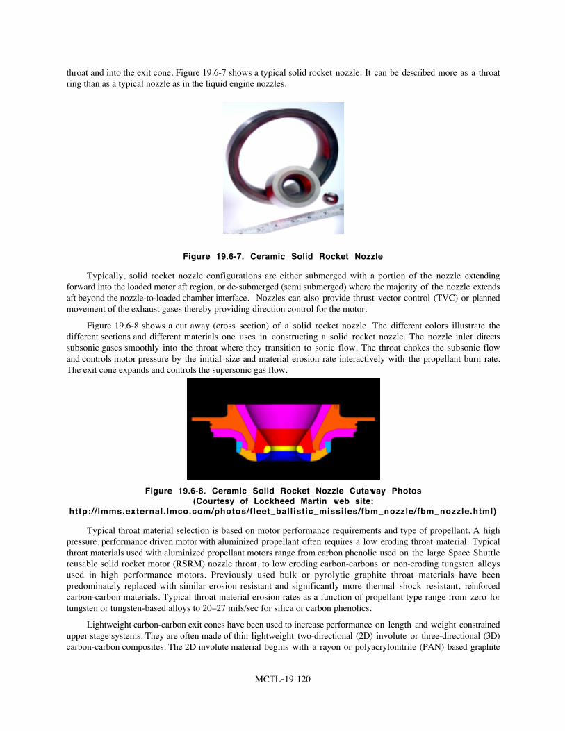
MCTL-19-120
throat and into the exit cone. Figure 19.6-7 shows a typical solid rocket nozzle. It can be described more as a throatring than as a typical nozzle as in the liquid engine nozzles.
Figure 19.6-7. Ceramic Solid Rocket Nozzle
Typically, solid rocket nozzle configurations are either submerged with a portion of the nozzle extendingforward into the loaded motor aft region, or de-submerged (semi submerged) where the majority of the nozzle extendsaft beyond the nozzle-to-loaded chamber interface. Nozzles can also provide thrust vector control (TVC) or plannedmovement of the exhaust gases thereby providing direction control for the motor.
Figure 19.6-8 shows a cut away (cross section) of a solid rocket nozzle. The different colors illustrate thedifferent sections and different materials one uses in constructing a solid rocket nozzle. The nozzle inlet directssubsonic gases smoothly into the throat where they transition to sonic flow. The throat chokes the subsonic flowand controls motor pressure by the initial size and material erosion rate interactively with the propellant burn rate.The exit cone expands and controls the supersonic gas flow.
Figure 19.6-8. Ceramic Solid Rocket Nozzle Cutaway Photos(Courtesy of Lockheed Martin web site:
http:// lmms.external.lmco.com/photos/fleet_ballistic_missiles/fbm_nozzle/fbm_nozzle.html)
Typical throat material selection is based on motor performance requirements and type of propellant. A highpressure, performance driven motor with aluminized propellant often requires a low eroding throat material. Typicalthroat materials used with aluminized propellant motors range from carbon phenolic used on the large Space Shuttlereusable solid rocket motor (RSRM) nozzle throat, to low eroding carbon-carbons or non-eroding tungsten alloysused in high performance motors. Previously used bulk or pyrolytic graphite throat materials have beenpredominately replaced with similar erosion resistant and significantly more thermal shock resistant, reinforcedcarbon-carbon materials. Typical throat material erosion rates as a function of propellant type range from zero fortungsten or tungsten-based alloys to 20–27 mils/sec for silica or carbon phenolics.
Lightweight carbon-carbon exit cones have been used to increase performance on length and weight constrainedupper stage systems. They are often made of thin lightweight two-directional (2D) involute or three-directional (3D)carbon-carbon composites. The 2D involute material begins with a rayon or polyacrylonitrile (PAN) based graphite

MCTL-19-121
phenolic preform that is subsequently carbonized, densified and graphitized at high temperatures to achieve a freestanding - high temperature ablative liner-structure.
There are several processes to fabricate nozzle components using refractory metals. The oldest and most wellestablished is forging methods. Pure tungsten, rhenium, and their alloys can and are made using these very old andreliable techniques. The billets made using these processes are typically expensive, thick, and require time-consuming machining steps. However, refractory metals made using these methods are the best characterized andprovide a baseline for comparison.
Less well-developed processes for manufacturing articles using these materials include electroforming frommolten salts, laser assisted manufacturing (LAM), chemical vapor deposition (CVD), vacuum plasma spraying(VPS), and powder injection molding techniques. Each has its particular advantages. These new techniques lendthemselves to making net- or near-net-shaped components in a fairly rapid manner (weeks rather than months). Thesenew materials are not identical to the forged alloys, but are good reproducible materials. Limited work has been doneto evaluate most of them and the feasibility of using them in solid fuel rocket motor nozzles. Many of thesetechniques have been and are being used currently in small rocket nozzles and thrust chambers for liquid engines usedon satellites and in other applications where the nozzle environment is not as severe.
MCTL-19-122
MCTL DATA SHEET 19.6-9. SOLID ROCKET PROPULSION
Critical TechnologyParameter(s)
Overall motor level:• Total Impulse, I(t) > 1.1 MN F(vac)> 220 kN;• Specific Impulse, Isp (vac) > 2.4 kN/kg;• Stage mass fraction > 88%; and• Propellant solids loading > 86%.This technology also addresses the propellant/insulator interface liner. The Spacelaunch propellant/insulator interface liner must have high bond strength.• A bond strength > the propellant cohesive strength; and• Bond strength that is maintained for > 10-year life cycle
Critical Materials For the liner, the combinations of the materials and the manufacturing steps for bothliner and propellant are critical. These critical materials and material processes producesolid rocket motors with significantly higher mass fraction and higher energy thancompeting technologies.
Unique Test, Production,Inspection Equipment
Production:• Specialized SRM production equipment, for mixing, casting and lining.• Unique production parameters and equipment for curing.Testing:• Motor test stands and associated hardware.Inspection:• None identified.
Unique Software • Computer codes that are unique to the optimization of solid rocket motorpreliminary designs.
• Motor ballistics performance codes.• Integrated SRM analyses—that is codes which link discreet analyses to form
overall motor solutions.• Custom subroutines or material databases.
Major CommercialApplications
Commercial applications of Solid Rocket Motors are found in the commercial launchindustry. Solid rocket motors are used as primary launch vehicle applications and asstrap-ons to liquid launch vehicles for thrust augmentation.
Affordability Issues None identified.Export ControlReferences
WA ML I and 8; WA Cat 1C, and 9; CCL Cat 1, 6B, and 8; USML V; MTCR 17.
BACKGROUND
A solid rocket motor is a completely self-contained heat engine used to convert latent chemical energy intothrust. Solid rocket motors (SRMs) generate thrust by exhausting combustion products through a supersonic nozzle.Although there is much to know about the science, engineering, and manufacture of SRMs, they are eloquentlysimple devices. Central to the simplicity of SRMs is preplacement of the propellant in the combustion chamber.This results in few moving parts, and low part count. SRMs consist of four main components: 1) a propellant grain;2) an insulated thrust chamber; 3) an igniter; and 4) a nozzle. The propellant grain consists of the propellant charge,in a geometry designed to deliver the desired thrust profile. The thrust chamber contains the pressure of propellant
MCTL-19-123
combustion, and is frequently a major portion of the vehicle airframe. Insulation is necessary to protect the thrustchamber structure from the high-temperature (6000 °F) combustion products. The igniter provides the substantialheat necessary to initiate combustion at the propellant surface. The nozzle directs and accelerates the propellantexhaust gasses.
The propellant is in solid form, completely housed within the combustion chamber. Rocket thrust dependsprimarily on the mass flow rate of propellant exhaust through the nozzle. The exhaust mass flow rate is essentiallythe same as the rate of generation of combustion products within the combustion chamber. In liquid rocket engines,the exhaust rate equals the rate at which propellant is fed into the combustion chamber. With SRMs, the mass flowrate depends on the burn rate of the propellant, the propellant density, and on the burning surface area size. Burn rateis a propellant characteristic, which can be formulated over a wide range during development, and held to closetolerance during production. Burning surface area depends on propellant grain geometry. Since the geometry is fixed,the thrust profile is pre-determined. Because it is not necessary to feed propellant into the combustion chamber,SRMs can be designed to deliver very high thrust levels compared to liquid rocket engines. Solid rocket propellant istypically a rubber-based material, with texture and elasticity similar to that of a pencil eraser. A typical state of theart booster propellant contains a mixture of 15-percent rubber binder, 20-percent Aluminum fuel, and 65-percentAmmonium perchlorate oxider. These formulations offer low cost, high density, good specific impulse, insensitivityto accidental ignition, 10+ year shelf life, tailorable mechanical properties, and tailorable burn rate. Mechanicalproperties are targeted such that the propellant grain is stiff enough to hold its shape, while being pliable enough sothat it does not crack.
Directional control is attained through a number of different means, but commonly the nozzle is jointed so itcan be vectored by mechanical actuators.
MCTL-19-124
MCTL DATA SHEET 19.6-10. COMPOSITE MOTOR CASES
Critical TechnologyParameter(s) • All Composite Motor Cases with diameters > 0.61 m (2 ft or 24 inches);
• Structural Efficiency; PV/W > 25 km (1 x106 inches);
• Specific Strength > 12 x 106 inches; and
• Specific Stiffness > 600 x 106 inches.Critical Materials Resins are critical to composite motor case improvements. The key elements of resins
include:
• Improved high-temperature resins; and
• Longer shelf life resins.
See Table 19.6-3 for typical motor case material comparisons. Comparisons or themeasure of case performance is usually performed using mass fraction or PV/W for therocket motor case and specific strength and stiffness for the material.
Unique Test, Production,Inspection Equipment • Production—4 and 5 axis filament winding machine.
• 3, 4 and 5 degrees of freedom braiding machine.
• Large winding and curing equipment.
• Acoustic Emission measurement equipment specially designed to access thehealth of composite motor case structures.
• The Levels and Rates of proof testing for large composite structures such as solidrocket motors is considered militarily critical.
• Proof testing, burst testing and how this relates to material strength/capability,safety factor and margin of safety is also militarily critical.
• High performance solid rocket motor cases may use any or all of the following:dome caps, dome reinforcement, and wafers (hoop reinforcement). The informationrelating to the design, analysis, and fabrication of these components is consideredmilitarily critical.
Unique Software None identified.Major CommercialApplications High strength/stiffness composite materials are used in many commercial applications
even commercial solid rocket motors.
• Tanks for commercial launch vehicles;
• Fairings and other components for military and non-military aircraft;
• Sporting goods; and
• C&G tanks and other high performance storage tanks.Affordability Issues High strength, and stiffness carbon fiber is becoming more readily available, due to its
low cost, and therefore being used is a wide array of commercial products. Fibers suchas M30S, and T700 are use to create relatively cheap high performance compositematerials used for many applications. While the use of composite materials, especiallycomposites utilizing carbon fiber, expands in the commercial world, information in solidrocket motors applications should not be made readily available.
Export ControlReferences WA ML 10, 21, and 22; WA Cat 9; MTCR 3; USML IV; CCL Cat 9.

MCTL-19-125
BACKGROUND
Current state-of-the-art (SOTA) large solid rocket motors (not tactical) are almost universally made from, atleast in part, composite materials. This primarily includes the family of carbon fiber/epoxy resins. Beginning in theearly 1960s with the Minuteman third stage and Polaris rocket motor cases, almost all subsequent motor cases forballistic missiles have been built from composite materials (fiber and epoxy resin). The material generally used hasthe highest specific strength (strength/weight) and specific stiffness (modulus/weight) of materials that have beencurrently developed and are commercially available. Initially the materials used in high performance composite casescomprised of fiber such as S2 glass (first generation), then progressed to Arimid fiber such as Kevlar 49 (secondgeneration), then progressed to the lower strength carbon fibers such as AS4 and now has progressed to higherstrength carbon fibers such as IM7 or T1000 (third generation). These fibers are predominately used in an epoxymatrix or resin with a Tg of less that 300 °F. There has not been a lot of advancement in new fibers or pushing thestrength of current carbon fibers for the last 10 years or more with the notable exception of the introduction of PBOand M5.
Table 19.6-2 shows the values for typical materials used for solid rocket motor cases.
Table 19.6-2. Comparison Efficiency, Strength and Stiffness of motor case materials. Thosein blue are considered militarily critical technology.
Motor Case Material
PressureVessel
EfficiencyPV/W
(inch × 106)
SpecificStrength
(Inch ×106)
SpecificStiffness
(Inch ×106)
Glass 0.93 5.43 136Kevlar 49 Aramid 1.38 9.57 347
T300 Carbon 1.24 8.05 525M30SC Carbon 1.94 12.7 683T1000G Carbon 2.19 14.2 657
PBO 2.22 15.1 692M5 3.40 22.4 1010
The above listed carbon fibers along with many others are used in commercial products, which may or may notbe related to solid rocket motor applications; however, information used to design, process, and improve materialstrength as it relates to solid rocket motor composite cases is considered militarily critical and should not bedisclosed.
Table 19.6-1 makes it apparent that delivered fiber strength is critical for high performing rocket motor cases.Using Composite cases for commercial rocket motors is now becoming common in highly developed countries(United States, Europe and Japan). However, the technology (design, and analysis tools) on how to design, analyzeand fabricate a large composite solid rocket motor case is not readily available and is not common knowledge. Thisinformation is closely held by several large manufacturing companies in the United States, Europe and Japan. Japan(NASDA / Nissan) recently purchased the technology from ATK Thiokol to fabricate the SRB-A for the HII-Alaunch system. The material system used in this motor is T1000/TCR.
The design methods, equations, database, tools (software) and other technology needed for the design, analysis,and fabrication of solid rocket motors cases should continue to be controlled. This should include the design methodsfor sizing and designing the port reinforcement wafers and polar boss or port adaptors.

MCTL-19-126
Motor Case Materials
Carbon fibers case materials (see Table 19.6-1) along with many other composite materials are used incommercial products, which may or may not be related to solid rocket motor applications.
The fibers are usually combined with an epoxy resin (25–35 percent by weight) to make up the compositematerial. The resins typically used must be stored in a cold box however; recently developed resins can be stored atambient temperature for extended periods of time. In most cases the resin used for solid rocket motor cases have a Tgabove 250 °F. In some cases the resin may even have a higher Tg than its cure temperature (temperature at which theresin “transitions” (T) from a hard, glassy state (g) to a soft rubbery state is called its Tg).
It is primarily the information on the material system after the fiber and resin are combined and used in thecomposite form that the information becomes valuable to the composite case designer/analyst. The fiber suppliertypically publishes fiber properties and the data is readily available. This is also often the case with resins. Howeverwhen the two are combined and processed into a composite on a large solid rocket motor case the informationbecomes more critical. The published strand data must be reduced to an allowable (fiber strength translation) whichcan be used in the pressure vessel as the failure strength.
Attaching the skirts, which takes the external loads and transfers it from payload to pressure vessel cylinderwall, is typically done with an elastomeric shear ply. The skirts are typically separated from the pressure vessel byan elastomeric shear ply or are attached in some other method. This elastomeric material and the design of thisinterface are critical to the performance of the solid rocket motor. The general information surrounding this interfaceis generally known and understood but the specific design and processing detailed information of this interface aregenerally not readily available.
Commercial Solid Rocket Motors Cases
Almost universally most solid rocket motor cases have had their genesis in military programs. The material,and technology is first developed for a military or government launch vehicle and then transitions to the commercialsector. Most high performance ballistic missile systems today contain at least some high performance compositematerial. This technology is then carried over into commercial application. However, the Minuteman systemcurrently being refurbished is based on a steel first stage.
MCTL-19-127
MCTL DATA SHEET 19.6-11. THRUST VECTOR ACTUATION SYSTEMS
Critical TechnologyParameter(s) DC motor power density: > 0.02 hp/cm3;
Battery specific energy: > 500 W-hr/kg;
Battery specific power: > 5 kW/kg; and
Battery combined specific energy and power: > 200 W-hr/kg and > 200 W/kg.Critical Materials DC Motors: Rare earth magnets (e.g., Samarium Cobalt (Sm-Co), Neodymium-Iron-
Boron (Nd-Fe-B)).
Batteries: Lithium alloy batteries (e.g., Li(Al) FeS2, Li(Si) FeS2).Unique Test, Production,Inspection Equipment Test: None identified.
Production: None identified.
Inspection: None identified.Unique Software None identified.Major CommercialApplications Launch vehicles (manned and unmanned), satellites, aircraft (manned and unmanned)
control surfaces, robots, manufacturing machinery.Affordability Issues None identified.Export ControlReferences WA ML 4, 22; WA Cat 9; MTCR 2; USML IV; CCL Cat 9.
BACKGROUND
The purpose of Thrust Vector Actuation (TVA) and the Thrust Vector Control (TVC) is to regulate turningmoments on a vehicle by regulating the side thrust direction and magnitude in proportion to guidance and controlsystem commands. The TVA is a sub-component of the thrust vector control system and consists of the mechanismsthat accomplish TVC. These mechanisms can be relatively simple but involve critical valves that regulate fluidinjection into the flow of a nozzle or throttling the thrust by controlling the nozzle throat area. The mechanisms tomanipulate devices that redirect the flow from a fixed nozzle such as jet vanes or flaps require a complex system. Thecapability to actually change the direction of the nozzle requires mechanisms with a higher power output andsometimes a very complex design.
Many innovative design concepts have been developed to accomplish these methods of thrust vector control.The liquid injection thrust vector control system uses a valve to regulate the amount of fluid injected into the flowpassing through a fixed nozzle and causes a disturbance to the flow that is also amplified due to the subsequentchemical reactions. This results in a diversion of the flow and produces side forces. Other methods to redirect theflow using a fixed nozzle has been accomplished by moving objects into the flow path such as vanes, flaps, orsections of the nozzle exit cone. These methods require lower power but usually produces losses in thrust that are notacceptable. Another method with fixed nozzles is to align small nozzles such the resultant thrust produced is a sideforce and the magnitude is regulated with valves that control the flow of gases through each nozzle. Moving thenozzle to redirect the thrust forces has produced larger side forces. This has been commonly accomplished withhydraulic actuators or pneumatic actuators. With the recent advancements in technology relative to electronics andelectric motors, electro-mechanical actuators have become more desirable. These advancements in technology havebeen accomplished through both government and commercial research.

MCTL-19-128
MCTL DATA SHEET 19.6-12. THRUST VECTOR CONTROL SYSTEMS
Critical TechnologyParameter(s) Military critical technologies are those that increase the thrust vector angle, the slew
rate or rate of change of the thrust vector, and the angular acceleration capabilityabove the following levels:
• Total Thrust Vector Angle > 8 degrees in magnitude;
• Thrust Vector Angular Velocity > 40 deg/sec; and
• Thrust Vector Angular Acceleration > 40 deg/sec2.
Critical Materials High-temperature and erosion resistant metal, metal matrix or ceramic compositematrix for intrusive vane.
Materials possessing both high strength and strain to failure capability for shimapplications.
High-temperature composite materials and insulators/shim materials that can withstandconstant temperatures > 2000 °F.
Elastomeric materials possessing high ultimate strength and strain capability, and highcompressive load capability.
Unique Test, Production,Inspection Equipment Production: special machining or forming of high temperature, erosion resistant
materials, shim manufacture, controllers, special manufacturing processes associatedwith the type of TVC concept.
Test: high temperature and high deformation strain gages and high capabilitythermocouples
Unique Software Specially developed design and analysis codes.
Control software.Major CommercialApplications • Commercial launch vehicles;
• Off-shore drilling platforms currently use a type of flexible bearing very similar tothose used in rocket motors; and
• Commercial helicopter bearings.Affordability Issues When developed this technology will allow increased performance by lowering weight
but at an increased cost.Export ControlReferences WA ML 4 and 22; WA Cat 9; MTCR 11; USML IV and VIII; CCL Cat 9.
BACKGROUND
The most common thrust vector control system uses of moveable nozzles. The most common type ofmoveable nozzle currently uses a flex bearing TVC system. Thrust vector control (TVC) is the use of external means(typically mechanical or fluidic) to alter the direction of the thrust, thus changing the direction of the missile’s flightpath. Figure 19.6-9 shows how one type of TVC, a movable nozzle, creates a turning moment on the missile equalto the thrust times the moment arm. TVC systems can be configured to provide control in all 3 axes: pitch (up anddown motion), yaw (side to side motion), and roll (rotation about the longitudinal axis of the missile).
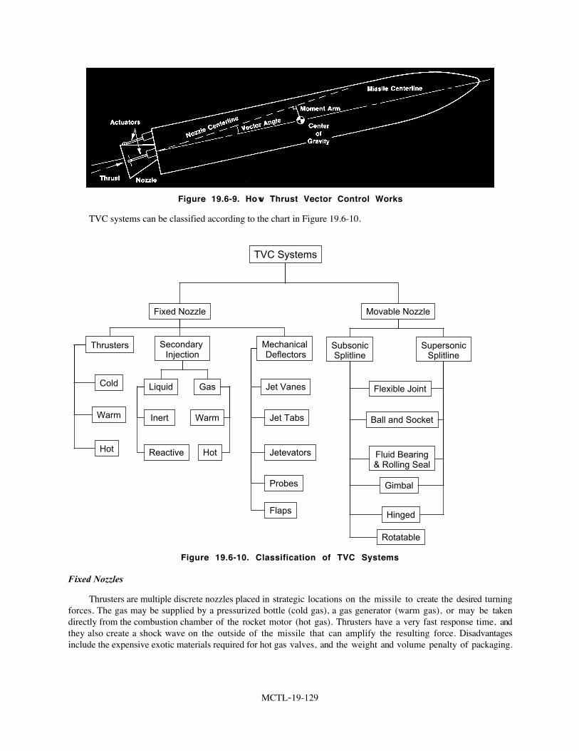
MCTL-19-129
Figure 19.6-9. How Thrust Vector Control Works
TVC systems can be classified according to the chart in Figure 19.6-10.
Figure 19.6-10. Classification of TVC Systems
Fixed Nozzles
Thrusters are multiple discrete nozzles placed in strategic locations on the missile to create the desired turningforces. The gas may be supplied by a pressurized bottle (cold gas), a gas generator (warm gas), or may be takendirectly from the combustion chamber of the rocket motor (hot gas). Thrusters have a very fast response time, andthey also create a shock wave on the outside of the missile that can amplify the resulting force. Disadvantagesinclude the expensive exotic materials required for hot gas valves, and the weight and volume penalty of packaging.
TVC Systems
Fixed Nozzle
Secondary Injection
Mechanical Deflectors
Movable Nozzle
Thrusters SubsonicSplitline
SupersonicSplitline
Liquid Gas
Inert
Reactive
Warm
Hot
Cold
Warm
Hot
Jet Vanes
Jet Tabs
Probes
Flaps
Jetevators
Flexible Joint
Ball and Socket
Fluid Bearing& Rolling Seal
Gimbal
Hinged
Rotatable

MCTL-19-130
Thrusters are used on the fourth stages of Minuteman III and Peacekeeper. Fixed nozzle systems use thrusters,secondary fluid injection, or mechanical deflectors to change the thrust vector direction.
In secondary injection TVC, a fluid (liquid or gas) is injected into the exit cone through the wall. This createsside forces from a combination of the thrust of the injectant jet and pressure imbalances from shock waves. Theinjectant can be an inert or reactive liquid, in which a chemical reaction results in additional side force. Gas injectantscan be from gas generators (warm) or can be bled directly from the motor combustion chamber (hot). Advantagesinclude fast response and the thrust addition to the main flow. Disadvantages are the large packaging volume requiredand limited thrust deflection (about 6°). Liquid injection systems have been in production on the Titan III,Minuteman III, and Polaris. Gas injection systems suffer from material problems in the severe environment and havenever reached production status.
Movable Nozzles
In movable nozzle systems, the nozzle is mechanically pivoted, which turns the hot supersonic flow of gasses,thus changing the thrust vector. Movable nozzles are further subcategorized according to the location of the joint. Ifthe entire nozzle and exit cone pivot as a unit, it is called a subsonic splitline. With the supersonic splitline, onlythe aft part of the exit cone pivots. Each has advantages and disadvantages. However, the supersonic splitline hasnever been in production due to manufacturing challenges.
Movable nozzles have lower thrust losses than the other types of TVC. However, a single movable nozzlecannot provide any roll control, which requires at least two nozzles. The Minuteman uses four, hinged movablenozzles for pitch, yaw, and roll control, and the Space Shuttle has two booster motors with movable nozzles.
The different types of TVC systems, their advantages, disadvantages, and application to production rocketmotors are summarized in Table 19.6-3.
Table 19.6-3. Summary of TVC SystemsTVC Type Advantages Disadvantages Application
Thrusters • Fast response• Side force amplification• 3-axis control
• Exotic materials• Packaging volume
• Spacecraft attitude control• Minuteman and Peacekeeper
Stage IVLiquid Injection • Fast response
• Thrust augmentation• Large packaging volume• Limited TVC angle
• Titan• Minuteman• Polaris
Jet Vanes • 3-axis control• Low actuation torque• Proven
• Exotic materials• Thrust losses
• German V-2• Sergeant• Talos• Pershing• Seasparrow• Vertical-Launch ASROC• French MICA• German IRIS• South African DARTER
Jet Tabs • Rapid response• Low actuation torque
• Exotic materials• Thrust losses• No roll control
• Tomahawk booster (MK-106)
Jetevator • Linear side force • Large packaging volume• Exotic materials• Thrust losses
• BOMARC• SUBROC• Russian AA-11
(Continued)
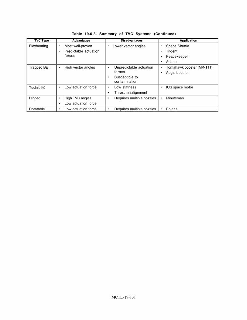
MCTL-19-131
Table 19.6-3. Summary of TVC Systems (Continued)TVC Type Advantages Disadvantages Application
Flexbearing • Most well-proven• Predictable actuation
forces
• Lower vector angles • Space Shuttle• Trident• Peacekeeper• Ariane
Trapped Ball • High vector angles • Unpredictable actuationforces
• Susceptible tocontamination
• Tomahawk booster (MK-111)• Aegis booster
Techroll® • Low actuation force • Low stiffness• Thrust misalignment
• IUS space motor
Hinged • High TVC angles• Low actuation force
• Requires multiple nozzles • Minuteman
Rotatable • Low actuation force • Requires multiple nozzles • Polaris
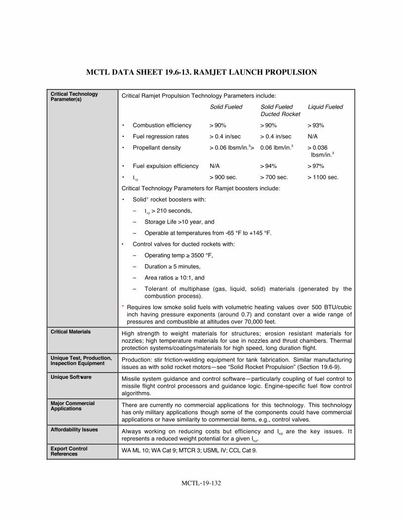
MCTL-19-132
MCTL DATA SHEET 19.6-13. RAMJET LAUNCH PROPULSION
Critical TechnologyParameter(s) Critical Ramjet Propulsion Technology Parameters include:
Solid Fueled Solid Fueled Liquid FueledDucted Rocket
• Combustion efficiency > 90% > 90% > 93%
• Fuel regression rates > 0.4 in/sec > 0.4 in/sec N/A
• Propellant density > 0.06 lbsm/in.3> 0.06 lbm/in.3 > 0.036lbsm/in.3
• Fuel expulsion efficiency N/A > 94% > 97%
• Isp > 900 sec. > 700 sec. > 1100 sec.
Critical Technology Parameters for Ramjet boosters include:
• Solid* rocket boosters with:
– Isp > 210 seconds,
– Storage Life >10 year, and
– Operable at temperatures from -65 °F to +145 °F.
• Control valves for ducted rockets with:
– Operating temp ≥ 3500 °F,
– Duration ≥ 5 minutes,
– Area ratios ≥ 10:1, and
– Tolerant of multiphase (gas, liquid, solid) materials (generated by thecombustion process).
* Requires low smoke solid fuels with volumetric heating values over 500 BTU/cubicinch having pressure exponents (around 0.7) and constant over a wide range ofpressures and combustible at altitudes over 70,000 feet.
Critical Materials High strength to weight materials for structures; erosion resistant materials fornozzles; high temperature materials for use in nozzles and thrust chambers. Thermalprotection systems/coatings/materials for high speed, long duration flight.
Unique Test, Production,Inspection Equipment Production: stir friction-welding equipment for tank fabrication. Similar manufacturing
issues as with solid rocket motors—see “Solid Rocket Propulsion” (Section 19.6-9). Unique Software Missile system guidance and control software—particularly coupling of fuel control to
missile flight control processors and guidance logic. Engine-specific fuel flow controlalgorithms.
Major CommercialApplications There are currently no commercial applications for this technology. This technology
has only military applications though some of the components could have commercialapplications or have similarity to commercial items, e.g., control valves.
Affordability Issues Always working on reducing costs but efficiency and Is p are the key issues. I trepresents a reduced weight potential for a given Is p.
Export ControlReferences WA ML 10; WA Cat 9; MTCR 3; USML IV; CCL Cat 9.

MCTL-19-133
BACKGROUND
There are three types of ramjet propulsion systems; solid fueled, liquid fueled, and solid fueled ducted rocket.The militarily critical components that enable successful ramjet missile operations are vehicle: propulsion systems,air inlet design, ignition systems, solid fuel gas generators, combustion sustainment methods, booster design,vehicle guidance controls and cooling systems for long flight times. All of these components are covered as separatecritical technologies. Also included in the militarily critical components list are: solid gas generator control valvedesign and flow control logic (ducted rockets) and the fuel injector design (ducted rockets and liquids). Ramjets are atechnology that has application for anti-satellite rockets and as a dual propulsion system for launches that combinesrockets and air-breathers.
Ramjet propulsion has been used for over 50 years. A number of nations currently operate or have thecapability to deploy ramjet-powered missiles, most notably France, the UK, Germany, China and Russia. It greatlyincreases the range and speed of these systems resulting in significant military capability. Ramjets use atmosphericoxygen as the oxidizer and can use either solid fuel gas generators or liquid fuels to provide the necessary fuel.Ramjets have to be boosted, usually by a solid rocket motor, to a speed at which the ramjet can be ignited and takesover as the primary propulsion. The U.S. Government has pursued joint missile development programs in the pastwith the UK and ramjet propulsion was one of the candidate technologies for that system. The United States mayseek a cooperative program again in the future.

MCTL-19-135
SECTION 19.7—PROPULSION FOR SPACE SYSTEMS
Highlights
• Electrical propulsion technologies are available in several power levels, ranging from low-power systemsuseful in maneuvering microsatellites/nanosatellites through medium-power to high-power systems usefulin orbit raising, space-based maintenance, and other space-based maneuvering applications.
• Chemical propulsion technologies cover both long-term storable and cryogenic propellant based systems.Technologies include solid propellant and liquid propellant based technologies. Chemical propulsionprovides high thrust to rapidly move satellites. They are used for orbit transfer, final orbit insertion, and forrepositioning.
• Cryogenic storage and refrigeration technologies with low loss rates, are required for use of liquid oxygen(LOX), liquid hydrogen (LH2), and liquid fluorine propellants in space.
OVERVIEW
The technologies addressed in this section are associated with in-space propulsion of satellites and spacecraft.They are used to provide satellites with attitude control, station keeping, orbit maintenance, and repositioning. Inaddition, these technologies can be and are used to assist in placing satellites into their proper orbits, includingcircularization, orbit topping, and orbit raising.
Orbit transfer vehicle (OTV) propulsion is also covered in this section, but upper stages for launch vehicles arenot. The former tends to operate between low earth orbit and other orbits, e.g., geosynchronous. OTVs can be usedto move satellites from one orbit to another, i.e., to a higher orbit or to a different orbital plane, or they can be usedto rescue a satellite that was not put into its proper orbit. Upper stage systems are part of the space launch vehicle.They provide the added lift capability for very heavy payloads and for payloads needing to get to very high orbits,e.g., geosynchronous. Upper stage propulsion is addressed under Launch Propulsion Systems, Section 19.6. Thedefinition of an upper stage can vary from one person to another. A review of this section and Launch PropulsionSystems is prudent.
Many of the technologies found in this section are also used by the commercial market to power theirsatellites. This section addresses the critical performance levels that provide significant military capability, thatwhich is above and beyond what is needed by the commercial market place. The technologies in this section are alsodependent on or have relationship with technologies found under Launch Propulsion for Space Systems (Section19.6), Space Optics (Section 19.4), Power and Thermal Management (Section 19.5), and Space Sensor Systems(Section 19.8).
The technologies addressed in this section include low, medium, and high power electric propulsion, storageand refrigeration for cryogenic propellants, and chemical propulsion. The United States has over the last ten yearstaken advantage of opportunities to collaborate, cooperate, and leverage the former Soviet Union, now Russian,technical lead in Hall Effect thrusters to bring that capability to U.S. space systems. It is being used on both U.S.commercial and government satellites today. The United States continues to further developments in this area andothers to ensure parity and superiority in satellite propulsion.
BACKGROUND
In-space propulsion for satellites is used for attitude control, station keeping, orbit maintenance, repositioning,assist in placing satellites into their proper orbits, including circularization, orbit topping, and orbit raising. This isa diverse set of mission requirements requiring significantly different propulsion systems. Historically cold gas andchemical systems were used, greatly limiting the operational life of the satellite. Currently liquid oxygen/liquid

MCTL-19-136
hydrogen (LOX/LH2) and nitrogen tetroxide/monomethyl hydrazine (NTO/MMH) are the predominant chemicalsystems for orbit raising. Solid propellant upper stages are also used not only for orbit raising but also for apogeetopping and final insertion.
LOX and LH2 have relatively short lives on orbit due to the cryogenic nature of these propellants. They requirestorage and refrigeration, yet they provide the greatest propulsive performance. NTO/MMH propellants are storablebut highly toxic, and they have about 1/3 less performance than LOX/LH2. Hydrazine is also used as amonopropellant in some systems. It too is highly toxic; it is also used in terrestrial applications, such as auxiliarypower units on aircraft.
Research in the United States and elsewhere, is focused on finding alternatives to the highly toxic propellants,which could very well be ready in the next five years for system designers to incorporate the technology into theirdesigns. Eliminating the toxic propellants will reduce overall system operating costs due to greater flexibility inhandling the materials. In addition, the propellants under development have better performance than hydrazine andpossibly even NTO/MMH. Thus, they will also provide increased capability in operational satellites.
The advent of various forms of electric propulsion since the 1980s through today have greatly improved on-orbit life and opened up other applications and opportunities to be exploited. Current electric propulsion systemsinclude ion, resistojets, and arcjets, which are used for station keeping, attitude control, and orbit maintenance.Resistojets and arcjets are early forms of electric propulsion systems that leveraged existing chemical systems addingsignificant heat thus increasing the engine’s efficiency. These are giving way to improved ion engines, pulsedplasma thrusters, and Hall Effect thrusters. These technologies provide greater efficiency, as well as greater control ofthe impulse bit; the latter is used to correct orbit variations due to atmospheric drag (on low earth orbit satellites),fluctuations in gravity, or effect of solar winds.
One limitation of electric propulsion systems is the amount of thrust they can produce. This is directly relatedto the amount of power available to the engine. The available power on satellites has steadily increased over theyears; 30 kW systems are now state of the art for large commercial communications satellites at geosynchronousearth orbit (GEO), and it is not unreasonable to expect developments to continue towards 100 kW satellites. Thiswill enable the use of electric propulsion in many applications where chemical systems now reign as the primarysource of propulsion.
Greater power for in-space propulsion systems yields greater thrust, which results in shorter trip times to placethe satellite in its proper orbit. Most satellites currently use chemical propulsion systems to put the satellite intofinal orbit within a few days. Current electric systems take tens of days to accomplish the same mission but withmuch better fuel efficiency. A significant benefit of electric propulsion systems is the significantly greater payloadmass they can place into orbit. So, currently, this is a trade between time to orbit and payload mass.
The commercial market seeks improved propulsion capability in order to place greater payloads into orbit andto increase on-orbit life, which translate into billions of dollars in increased revenue. The scientific community alsouses various mixes of chemical and electric propulsion to address their needs for in-space propulsion or interplanetarypropulsion. NASA develops satellites ranging from very small nanosatellites to very large orbiting telescopes andinterplanetary vehicles. The best propulsion system for a given mission is a system design issue specific to themission. It may be possible to use a chemical system, an electric system, or some combination of both.
As power availability increases, however, it appears that electric systems will be able to provide more and moreof the in-space propulsion capability spectrum. In addition, satellite payloads will be able to grow in mass, doublingor tripling in size over the next two decades, given expected improvements in both electric and chemical propulsiontechnologies.

MCTL-19-137
LIST OF MCTL TECHNOLOGY DATA SHEETS19.7. PROPULSION FOR SPACE SYSTEMS
19.7-1 Low-Power Electric Propulsion............................................................................... MCTL-19-139
19.7-2 Medium-Power Electric Propulsion.......................................................................... MCTL-19-140
19.7-3 High-Power Electric Propulsion.............................................................................. MCTL-19-141
19.7-4 Storage and Refrigeration—Cryogenic Propellant ....................................................... MCTL-19-142
19.7-5 Chemical Propulsion ............................................................................................ MCTL-19-143

MCTL-19-139
MCTL DATA SHEET 19.7-1. LOW-POWER ELECTRIC PROPULSION
Critical TechnologyParameter(s) • Hall Thruster efficiency > 40%;
• Pulsed Plasma Thruster efficiency > 12%;
• Colloid Thruster efficiency > 60%;
• Power processing unit efficiency > 91%; and
• Ion Engine efficiency > 70%.Critical Materials • Improved capacitor materials technology that reduces charge bleed off, internal
resistance of large capacitors, and specific charge is vital for the continueddevelopment of this field.
• Low specific mass, i.e., mass/energy, materials that exceed the capabilities ofDiamond film capacitors would have a significant impact on the performance ofPPTs.
• Pulsed plasma thrusters (PPTs) currently use Teflon® as a propellant. Propellantmaterials that improve, reduce or eliminate, late time ablation, (the continuedablation of the propellant after the pulse and after charged ions have dissipated) arecritical material.
Improved materials will have a significant impact on the efficiency of Pulsed plasmathrusters (PPTs).
Unique Test, Production,Inspection Equipment None identified.
Thrust stand capable of measuring thrust ≤ micron level and impulse bits at the micronlevel.
Unique Software None identified.Major CommercialApplications Orbit topping; orbit raising; orbit maintenance; station keeping; primary propulsion for
microsatellites/nanosatellites and attitude control for large medium sized spacecraft(i.e., replacement of reaction wheels). There may also exist interest in constellations offormation flying satellites which would use this type of propulsion.
Affordability Issues This technology will enable increased payload and simpler, less expensive thrusters formicrosatellites/nanosatellites and longer on-orbit life.
Export ControlReferences USML XV.
BACKGROUND
Low-power (< 200 W) electric propulsion is the portion of the electric propulsion technology spectrum thathas the most enabling technology for microsatellites/nanosatellites. For these satellites, it provides the onlyavailable propulsion. Low-power electric propulsion systems for microsatellites/nanosatellites will provide primaryon-orbit propulsion. Other uses include attitude control thrusters for larger, more conventional spacecraft.
For these satellites, it provides the only available propulsion. Low-power electric propulsion systems formicrosatellites/nanosatellites will provide primary on-orbit propulsion. Other uses include attitude control thrustersfor larger, more conventional spacecraft.
Thruster types include pulsed plasma thrusters, Hall thrusters, and colloid thrusters. Current development isconcentrating on improving efficiency, maximizing propellant use, and reducing thruster mass.
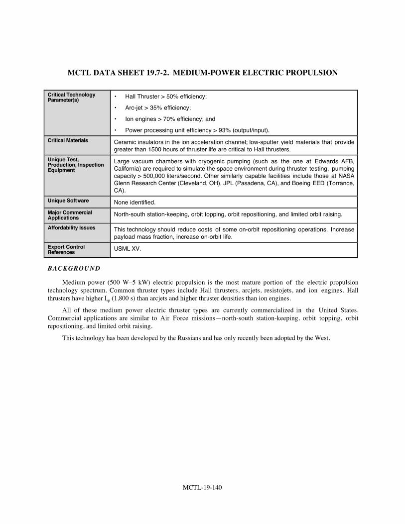
MCTL-19-140
MCTL DATA SHEET 19.7-2. MEDIUM-POWER ELECTRIC PROPULSION
Critical TechnologyParameter(s) • Hall Thruster > 50% efficiency;
• Arc-jet > 35% efficiency;
• Ion engines > 70% efficiency; and
• Power processing unit efficiency > 93% (output/input).Critical Materials Ceramic insulators in the ion acceleration channel; low-sputter yield materials that provide
greater than 1500 hours of thruster life are critical to Hall thrusters.Unique Test,Production, InspectionEquipment
Large vacuum chambers with cryogenic pumping (such as the one at Edwards AFB,California) are required to simulate the space environment during thruster testing, pumpingcapacity > 500,000 liters/second. Other similarly capable facilities include those at NASAGlenn Research Center (Cleveland, OH), JPL (Pasadena, CA), and Boeing EED (Torrance,CA).
Unique Software None identified.Major CommercialApplications North-south station-keeping, orbit topping, orbit repositioning, and limited orbit raising.
Affordability Issues This technology should reduce costs of some on-orbit repositioning operations. Increasepayload mass fraction, increase on-orbit life.
Export ControlReferences USML XV.
BACKGROUND
Medium power (500 W–5 kW) electric propulsion is the most mature portion of the electric propulsiontechnology spectrum. Common thruster types include Hall thrusters, arcjets, resistojets, and ion engines. Hallthrusters have higher Isp (1,800 s) than arcjets and higher thruster densities than ion engines.
All of these medium power electric thruster types are currently commercialized in the United States.Commercial applications are similar to Air Force missions—north-south station-keeping, orbit topping, orbitrepositioning, and limited orbit raising.
This technology has been developed by the Russians and has only recently been adopted by the West.

MCTL-19-141
MCTL DATA SHEET 19.7-3. HIGH-POWER ELECTRIC PROPULSION
Critical TechnologyParameter(s) Electric Propulsion Systems with an Isp < 2500 seconds with efficiencies > 55%.
Critical Materials None identified.Unique Test, Production,Inspection Equipment Large vacuum chambers with cryogenic pumping (such as the one at Edwards AFB,
California) are required to simulate the space environment during thruster testing,pumping capacity > 500,000 liters/second.
Unique Software None identified.Major CommercialApplications Orbit transfer vehicle applications; space tug; orbit raising; North-south station-keeping;
orbit topping; orbit repositioning.
Affordability Issues None identified.Export ControlReferences USML XV.
BACKGROUND
High-power (> 5 kW) electric propulsion is of interest because much higher power satellites are now beingbuilt which can provide the necessary power for these engines. Hall thrusters (Isp ~1800–2500 seconds) are theprimary engines of interest at these power levels. Arcjets can also operate at these power levels as well as ionthrusters. A 30 kW arcjet was developed by the Air Force and flown in the mid 1990s. The Air Force then changeddirection to pursue Hall thrusters because of their improved performance over arcjets.

MCTL-19-142
MCTL DATA SHEET 19.7-4. STORAGE AND REFRIGERATION—CRYOGENICPROPELLANT
Critical TechnologyParameter(s) • Loss rate: < 30% per year of cryogenic liquid (all chemical systems).
Critical Materials Lightweight, liquid oxygen-compatible tankage materials, high-fracture toughnesscryogenic tank materials, highly efficient thermal insulation, active thermal insulators,and compatible line, duct, tankage, gasket, and seal materials. For example, compositematerials are also being used for liquid oxygen storage due to the lightweight of thesematerials.
Unique Test, Production,Inspection Equipment Cryogenic fluids for testing and chemicals passivation.
Friction stir welding equipment for production.
Low- or zero-gravity test facilities. Vacuum jacketed equipment.Unique Software Adaptable for current simple control logic.Major CommercialApplications Except for the use of liquid oxygen, which is a common industrial chemical used in
welding and the medical industry, commercial applications for these technologies arespecialized niche markets (e.g., launch vehicles, satellite propulsion, upper-stagepropulsion, liquefied gas industry, and specialty chemical processes).
Affordability Issues These technologies, though expensive, tend to increase heavy lift capability, thusincreasing the effectiveness of on-orbit assets. They avoid the need for multiplelaunches and on-orbit assembly of some assets.
Export ControlReferences WA ML 20; WA Cat 9A; USML XV; CCL Cat 9A.
BACKGROUND
Cryogenic fluids, solids, slushes, and slurries must be maintained at temperatures below 100 K, with loss ratesless than 30 percent/year of storage. Cryogenic propellants retain a large amount of energy per unit mass and arehigh-efficiency rocket, missile, air vehicle fuels, and fuels for lasers. Liquid oxygen (LOX) and liquid hydrogen(LH2) are the current state-of-the-art fluids. Research is continuing on liquid fluorine, nitrogen/fluorine compounds,oxygen/fluorine compounds, slush hydrogen (also referred to as increased density propellant), slush oxygen, anddoped hydrogen and oxygen slurries. Cryogenic storage and refrigeration systems include fluid-compatible andimpermeable materials (tankage and seals), active and passive insulation systems, high-efficiency pumps andcondensers, heat exchangers, near-zero thermal shrinkage materials, and environmentally benign refrigerants.
Advances in this technology area are aimed at improving the refrigeration and storage efficiency at cryogenictemperatures, lengthening the duration of storage, broadening the types of fluids stored (to include semisolids), andstoring fluorine-based compounds.
See also cryocooler technologies used for cooling infrared sensor systems discussed in Section 19.8 and used ingeneral in power and thermal management systems in Section 19.5.
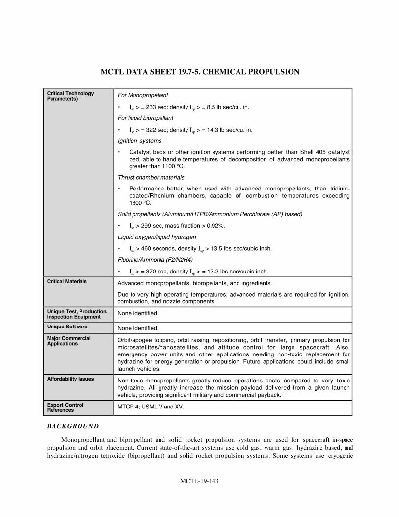
MCTL-19-143
MCTL DATA SHEET 19.7-5. CHEMICAL PROPULSION
Critical TechnologyParameter(s) For Monopropellant
• Isp > = 233 sec; density Isp > = 8.5 lb sec/cu. in.
For liquid bipropellant
• Isp > = 322 sec; density Isp > = 14.3 lb sec/cu. in.
Ignition systems
• Catalyst beds or other ignition systems performing better than Shell 405 catalystbed, able to handle temperatures of decomposition of advanced monopropellantsgreater than 1100 °C.
Thrust chamber materials
• Performance better, when used with advanced monopropellants, than Iridium-coated/Rhenium chambers, capable of combustion temperatures exceeding1800 °C.
Solid propellants (Aluminum/HTPB/Ammonium Perchlorate (AP) based)
• Isp > 299 sec, mass fraction > 0.92%.
Liquid oxygen/liquid hydrogen
• Isp > 460 seconds, density Isp > 13.5 lbs sec/cubic inch.
Fluorine/Ammonia (F2/N2H4)
• Isp > = 370 sec, density Isp > = 17.2 lbs sec/cubic inch.Critical Materials Advanced monopropellants, bipropellants, and ingredients.
Due to very high operating temperatures, advanced materials are required for ignition,combustion, and nozzle components.
Unique Test, Production,Inspection Equipment None identified.
Unique Software None identified.Major CommercialApplications Orbit/apogee topping, orbit raising, repositioning, orbit transfer, primary propulsion for
microsatellites/nanosatellites, and attitude control for large spacecraft. Also,emergency power units and other applications needing non-toxic replacement forhydrazine for energy generation or propulsion. Future applications could include smalllaunch vehicles.
Affordability Issues Non-toxic monopropellants greatly reduce operations costs compared to very toxichydrazine. All greatly increase the mission payload delivered from a given launchvehicle, providing significant military and commercial payback.
Export ControlReferences MTCR 4; USML V and XV.
BACKGROUND
Monopropellant and bipropellant and solid rocket propulsion systems are used for spacecraft in-spacepropulsion and orbit placement. Current state-of-the-art systems use cold gas, warm gas, hydrazine based, andhydrazine/nitrogen tetroxide (bipropellant) and solid rocket propulsion systems. Some systems use cryogenic
MCTL-19-144
propellants, such as liquid hydrogen and liquid oxygen. Hydrazine is also used in emergency power units, in kinetickill vehicles, and in post boost vehicles for ballistic missiles. Hydrazine and Nitrogen Tetroxide are highly toxic.Liquid oxygen is used in a number of terrestrial industrial applications. Both liquid hydrogen and liquid oxygen arerelatively easy to obtain from air or water.
Liquid propellant based systems can be divided into storable (e.g., hydrazine and nitrogen tetroxide) and non-storable (e.g. cryogenic propellants like liquid oxygen and liquid hydrogen). Storable propellants enable very longon-orbit life for satellites, providing maneuvering capability until the propellant is exhausted. Cryogenic basedsystems have much shorter on-orbit life times as the cryogenic propellants evaporate over time even when usingactive refrigerated storage techniques. For further information on advanced monopropellants, bipropellants, and solidpropellants, see the discussions on High Energy Propellant Ingredients and High Energy Propellants in Section 19.6.In addition, see discussion of cryogenic storage and refrigeration in this section for additional information related tostorage of liquid oxygen/liquid hydrogen and fluorine based propellants.
Solid rockets are used in upper stage and apogee topping applications. In the apogee topping application, theyare combined with electric propulsion systems to provide significant increases in mission payload. The highperformance of solid rocket propulsion is due to a combination of motor pressure, nozzle and propellant performance.See sections covering cases, nozzles, thrust vector and thrust actuation for additional critical materials related to solidrocket motors. For this additional information on solid rocket propulsion and related technologies, see Section 19.6,Launch Propulsion for Space Systems.

MCTL-19-145
SECTION 19.8—SPACE SENSOR SYSTEMS
Highlights
• Significant improvements in battlefield awareness and mission control have been achieved by multispectraland hyperspectral space sensor technologies.
• Space Sensors now provide near real-time information to the warfighter.
• Major improvements in measurement and signature intelligence (MASINT) software have made significanteffects in the speed and accuracy of data analyses and target identification.
• The military utility of both hyperspectral and multispectral space sensor systems has improved significantlywith the development of key software programs such as COSMEC.
• IR sensors are considered the most important items in missile warning optical space sensor systems, suchas the Defense Support Program (DSP), Space-Based Infrared System (SBIRS), NMD and TMD missions.
• Synthetic aperture radar (SAR) is particularly well suited to space applications, and researchers are investi-gating many new high-resolution improvements in this technology area.
• MASINT software technologies exploit advances in multispectral and hyperspectral target phenomenologyproviding fast, accurate and timely decision making inputs.
• Significantly improved signal processing, high-performance computing, and low-cost microelectronics havegreatly improved our space surveillance systems.
• Quantum well IR photodetectors (QWIPs) are particularly useful for space surveillance of cold objects. Theirmultispectral sensitivity and efficiency capability can be used with both high-resolution multispectral andhyperspectral response for greater discrimination between targets or in modes that produces a very broadbandresponse.
• Hyperspectral imaging has two major defense applications: characterizing the battlespace environment andidentifying tactical targets of military interest.
• Advanced space-based radar technologies are leading to a new generation of space-based intelligence, sur-veillance, and reconnaissance (ISR) systems, which will significantly impact the MASINT data base andultimately the warfighter.
• SAR relies on advanced radar algorithms, high-power aperture and sparse aperture concepts, as well asMMICs, RF photonics technology, and low-power, high-performance computing, which have all improvedsignificantly over the past decade providing space based SAR technology a significant boost.
• Nuclear detonation detection sensors for atmospheric tests, observed from space platforms, have proven aninvaluable tool in recent years as our eyes-in-the-sky.
OVERVIEW
Electro-optical, radar, and nuclear detonation surveillance from spacecraft play a major role in the U.S.surveillance program. Electro-optical surveillance has its origins in visual surveillance from tethered balloons duringthe Civil War and visual and photographic surveillance from aircraft and balloons during World War I. As technologyhas advanced, surveillance technologies in general have improved. Sophisticated high-altitude optical aircraftsurveillance has played a major role in gathering intelligence since the start of the Cold War.
With the advent of optical space platforms with onboard electro-optical sensors in the early 1970s, spacesensors have been providing an ever-increasing military advantage for both battlefield assessment as well as strategic
MCTL-19-146
operations. This has been true for both offensive and defensive military operations. The ability to have real timespace surveillance has proven to be of tremendous value for the modern battlefield warfighter. Space sensors allowthe examination of radiation, points of interest and objects on or near the earth for both tactical and strategicapplications on a continuing basis.
In addition, nuclear detonation detection of atmospheric bursts is a key deterrent to adversaries and has provenbeneficial to our national interests. The United States Nuclear Detonation Detection System (USNDS) technologydevelopment program carries crossover technologies. It leverages major investments already made in photonics,microelectronics, signal processing, high-performance computing antennas, and the latest advances in digitalreceivers and antenna arrays. These efforts have helped produce systems that have lower power requirements and arecapable of extracting improved target information from challenging background environments.
Thus, many technologies incorporated in or directly supporting space-based electro-optic, nuclear detonationdetection, and radar sensor systems are critical to U.S. national security. These are technology areas where we need tomaintain a leadership position.
BACKGROUND
Since the launch of the first space multispectral sensor, the Landsat 1 in early 1972, multispectral image datahave been used for numerous studies in a wide variety of fields. The success of Landsat and other multispectralsensors led to the development of the first hyperspectral imaging sensor. This was an airborne sensor known as theAirborne Imaging Spectrometer (AIS). The AIS was flown in 1982 by NASA’s Jet Propulsion Lab (JPL).Although multispectral imagery continues to be among the most widely used remote sensing data, hyperspectralimagery is maturing into one of the most powerful and fastest growing sources of remotely sensed information.
In general, multispectral sensors measure multiple, wide, separated wavelength bands whereas hyperspectralsensors generally measure multiple, narrow and contiguous wavelength bands. Although most hyperspectral sensorsmeasure hundreds of wavelength bands, and most multispectral sensors measure only a few, it's not the number ofmeasured wavelengths that defines if a sensor is multispectral or hyperspectral—it’s the narrowness and contiguousnature of the measurements that determines the difference of these instruments.
In cases where scattered sunlight or thermal radiation is not adequate to form images of sufficient detail andclarity, laser illumination can be used as an augmenting source of light. One such application is Light Detection andRanging: LIDAR. A LIDAR instrument transmits light out to a target. The transmitted light interacts with and/or ischanged by the target. Some of this light is reflected/scattered back to the instrument where it is analyzed. Thechange in the properties of the light enables some property of the target to be determined. The time for the light totravel out to the target and back to the LIDAR is used to determine the range to the target. LIDAR can be used todetermine an object’s distance, speed, rotation or chemical composition. Once the LIDAR is calibrated, themagnitude of the surface return can be used to obtain the surface reflectance or albedo. The spectral dependence of thesurface reflectance can be used to discriminate vegetation, camouflage or different land surface types. The high rangeresolution feature of LIDAR also provides the capability to generate high resolution 3-D image maps over areas ofinterest.

MCTL-19-147
LIST OF MCTL TECHNOLOGY DATA SHEETS19.8. SPACE SENSOR SYSTEMS
19.8-1 Cooled Infrared (IR) Focal Plane Detectors ................................................................ MCTL-19-149
19.8-2 Multispectral and Hyperspectral Space Sensor Systems................................................ MCTL-19-151
19.8-3 Space LIDAR Technology ..................................................................................... MCTL-19-153
19.8-4 Nuclear Detonation Detection Technologies............................................................... MCTL-19-154

MCTL-19-149
MCTL DATA SHEET 19.8-1. COOLED INFRARED (IR) FOCAL PLANEDETECTORS
Critical TechnologyParameter(s) 1. D* > 1011 (a normalized signal-to-noise measure, with effects of electronic
bandwidth and detector area removed [cm × Hz-1/2 / W]).
2. RoH > 105 (ohm-cm).
Note: These critical space detector parameters include focal plane arrays (FPAs),linear arrays and individual detector elements.
Critical Materials High purity Extrinsic materials such as Mercury Cadmium Telluride (MCT) andCadmium Zinc Telluride (CdZnTe), Si:X (where X is usually arsenic), PbS, InSb,GaInAs, and extrinsic semiconductors sensors including Si:As, Si:Ga, and Ge:Ga.and alloys called QWIPs, composed of various compounds including:GaAs/AlGaAs, Ga(1-Y)InYAs and Hg(1-X)CdXTe and other variations of these alloys.
Bolometer and thin-film ferroelectric materials (such as Bi2Te3 microstructurematerial) used for thermal electric coolers and temperature stabilizers for spacecomponents capable of cooling components to 175 K at > 2 W/cm2 heat removal.
Unique Test, Production,Inspection Equipment None identified.
Unique Software None identified.Major CommercialApplications Astronomy and Industrial Applications.
Affordability Issues Performance is demanding and yields are low for strategic applications, soaffordability is high (i.e., very expensive).
Export ControlReferences WA ML 15; WA IL Cat 6A; USML XII; CCL Cat 6A.
BACKGROUND
The term “sensor” in this context is used to describe an instrument that converts photons into electrical signals.This technology data sheet outlines the cooled detectors/sensors used in space-based infrared detection and imagingsystems.
Infrared (IR) radiation means optical radiation beyond the red wavelengths; conventionally thought of as thespectrum from 0.7–1,000 microns. The first patent for an IR application was filed circa 1910. The first IR sensorship detection occurred in 1917 at a range of one mile. Infrared sniper scopes were first used near the end of WWII.Cooled Infrared detector technology evolved to a state of high performance during the 1970s and early 1980s. Space-based surveillance and remote sensing is usually done with IR sensors at ranges up to 40,000 km.
A typical IR sensor is made up of many subsystems, including but not limited to: optics, detectors, such asfocal plane arrays, thermal controls, signal processing, and data storage and information handling and processingsystems. Photons incident upon the aperture of the sensor telescope are collected by the sensor optics, and focusedonto the detector. Focal plane arrays are composed of one or more s ensor c hip a ssemblies (SCA). The SCA handlesthe processing of incoming photons and outputs a voltage proportional to the number of photons absorbed oversome period of time (the integration time). This analog signal may undergo filtering, and then is typically convertedto a digital signal, which may undergo digital filtering prior to recording or downloading it. The signal may bedownlinked to a ground station for further processing, or may undergo further onboard processing. The result is eithera digitized image of the scene the sensor “sees” or an exceedance indicating the presence of a target within thesensor’s field of view.
MCTL-19-150
There are two classes of IR detectors used in space applications: thermal detectors using heating effects (e.g.,bolometers, thermopiles, pyroelectrics) and photon or quantum detectors that use a direct interaction between photonsand electrons. In this later category lies the three workhorse detector technologies for space-based optical sensorassets; e.g., mercury cadmium telluride (MCT), indium antimonide (InSb), and extrinsic silicon (Si:X where X isusually arsenic). Quantum well IR photodetectors (QWIPs) are also becoming more efficient and more plentiful for awide variety of applications. While thermal detectors are improving they are not sufficiently sensitive to replace thephoton detectors for use in space-based IR strategic and tactical applications; therefore this data sheet covers onlyphoton detectors.
QWIPs are advanced nanodevices that are fabricated using state-of-the-art semiconductor technology. They areusually of GaAs base material alloyed with other elements. The flexibility of the precision QWIP design andfabrication technology allows it to be optimized for a variety of mission conditions. Based on highly mature GaAsgrowth and processing technology, QWIPs can be used to produce large-format focal plane arrays for high-resolutioninfrared cameras at lower cost than any other competing technologies. The manufacturability of QWIP-basedadvanced infrared camera has enabled a rapid commercialization of this technology. The availability of QWIP camerashas already contributed to the advancement in medical applications. A novel QWIP-based breast cancer detectiontechnology was recently approved by the FDA. The high operability, high uniformity, high stability, and highradiation tolerance of QWIP cameras remarkably simplify the on-board and ground based data analysis for NASAmissions, thus providing a significant cost reduction in software development, data processing and major systemlevel benefits upon integration. As such, the QWIP technology will enable NASA’s vision of frequent and low costmissions in the 21st century.
Because of the demanding requirements for strategic space sensors, the performance characteristics of spaceFPAs are usually much higher than for a tactical system. In addition, detectors and focal plane arrays (FPAs) need tobe space qualified. A space qualified FPA is one that has met a stringent set of specifications, usually by extensivetesting. Since these FPAs may be used in a remote location for many years, greater emphasis is placed on packagingand reliability. All materials used to package the FPA must be certified for use in space. These FPAs must also passspecifications for some level of radiation hardness. But the detailed hardness specifications depend on the intendedmission and can vary by many orders of magnitude. Because of the widely varying performance requirements forstrategic space systems, SCAs or FPAs designed for one system may be totally inappropriate for another.
MCTL-19-151
MCTL DATA SHEET 19.8-2. MULTISPECTRAL AND HYPERSPECTRAL SPACESENSOR SYSTEMS
Critical TechnologyParameter(s) The critical defense technologies of multispectral and hyperspectral space sensor
systems include the specially developed algorithms for defense applications and thelevel of spatial vs. spectral resolution achievable for systems in the 100 nm to 1,000µ wavelength range. The critical technology parameters include the following:1. All image processing algorithms, autonomous channel correlations, automated
spectral mapping software tools designed and/or developed for military andother defense measurement and signatures intelligence interests;
2. Space Optical Sensor Systems with an instantaneous-Field-of-View (IFOV) of< 200 microradians and having a spatial resolution < 5 m within any of thesensor wavelength bands; or
3. Ground terminal instrumentation that receives, processes, and exploits MSIand/or HSI data for conversion into near-real time military data products.
Critical Materials Sensor materials with high uniformity and high purity. Extrinsic materials such asMercury Cadmium Telluride (MCT) and Cadmium Zinc Telluride (CdZnTe), Si:X (whereX is usually arsenic), PbS, InSb, GaInAs, and extrinsic semiconductors sensorsincluding Si:As, Si:Ga, and Ge:Ga. There are also alloys and bolometer sensor materials that are critical including:Ga(1-Y)InYAs, Hg(1-y)CdXTe, amorphous Silicon, Vanadium Oxide (VOx) and QWIPs.
Unique Test, Production,Inspection Equipment None identified.
Unique Software All specially developed software for defense analyses of multispectral andhyperspectral data and measurements such as COSMEC.
Major CommercialApplications Astronomy and Industrial Applications.
Affordability Issues Performance is demanding and yields are low for strategic applications, soaffordability is high (i.e., very expensive).
Export ControlReferences WA ML 15; WA Cat 6A; USML XV; CCL Cat 6A.
BACKGROUND
Optical remote sensing systems are classified into the following types for convenience, depending on thenumber of spectral bands used and their spectral separation in the imaging process—multispectral imaging systems(usually, a limited number of separated, wide spectral bands) and hyperspectral imaging systems (with many narrowcontiguous spectral bands). Both of these systems use spectral bands, which may be chosen from any portion of thespectrum—from ultraviolet to thermal-infrared. Automated spectral mapping tools and software algorithms aredesigned for each system to rapidly produce images, target IDs, movements, or other military signatures of interest.The software that reduces imagery from many space hyperspectral sensors, which is key to military intelligence, isknown in general as MASINT: Measurement and Signatures Intelligence. MASINT is technically derivedintelligence (excluding traditional IMINT and SIGINT) which when collected, processed, and analyzed, results inintelligence that detects, tracks, identifies, or describes the signatures of fixed or dynamic target sources.
The common denominator of all of these multispectral systems is their reliance on detection by identifying thetarget through its shape in the imagery. This forces the development of systems with improved spatial resolution inorder to detect smaller and smaller objects or objects partially hidden by surrounding materials. Hyperspectralimagery (HSI), while viewed by many as an extension of multispectral imagery, breaks this paradigm. With
MCTL-19-152
hundreds of spectral bands, hyperspectral systems basically obtain a spectrum of the energy reflected or emitted byeach element in the scene and identify an object (or a terrain element) from its spectrum, and does not depend on itsshape. Spectral identification is especially important for space systems, since at their much higher altitude, highspatial resolution comes at the high price of very large optics and optical pointing systems.
The difference between multispectral and hyperspectral imagery is the detail of the spectral signature and thecontiguous nature of hyperspectral imaging versus the separated band imaging in multispectral imaging. Mostmultispectral sensors take one measurement in a wide portion of each major wavelength band, such as visible blue,near infrared, etc. Hyperspectral, on the other hand, measures energy in numerous narrow units of each band.
Optical remote sensing makes use of visible, near infrared and short-wave infrared sensors to form images ofthe earth’s surface or objects on or near the earth’s surface by detecting the solar radiation reflected from targets onthe ground. Different materials reflect and absorb differently at different wavelengths. Thus, the targets can bedifferentiated by their spectral reflectance signatures in the remotely sensed images. This is a technology that hasroots in the civilian space program and is turning out to be highly relevant one for national security and the war onterrorism. Hyperspectral imaging, as the name implies, it is well-suited for perceiving things not readily seen—suchas camouflaged tanks, clouds of poison gas, and terrorists who attack and then hide.
The human eye perceives only the small, visible-light portion of the electromagnetic spectrum. Detectingphenomena via other portions of the spectrum, such as infrared or ultraviolet light, requires specialized cameras oreQWIPment. Multispectral and/or hyperspectral sensors gather data simultaneously in several portions of thespectrum. Hyperspectral devices operate across numerous slices of the spectrum, and typically are programmed torecognize chemical signatures and other subtle patterns in the objects under study.
Modern remote space sensing is marked by taking advantage of digital spectral image sensors and the markeddistinction with reflection in various bands of the spectra from different materials. Two specific kinds of spectralimaging systems, the multispectral and hyperspectral ones, have emerged and evolved for remote sensingapplications.
A multispectral imaging system collects images in a number of separate spectral bands that, depending on thesensor of the system, may be chosen from any portion of the spectrum from ultraviolet to thermal-infrared. Ahyperspectral imaging system acquires images of the same scene in many narrow, contiguous spectral bands over agiven spectral range. By adding wavelength as a third dimension to the image plane, the contiguous spectrum of anypixel in the hyperspectral scene can be accessed.
NASA has played a key role in pioneering and developing multispectral and hyperspectral imaging. Astronautson the 1968 Apollo 9 mission used a four-camera array to perform the first multispectral photography from space.More multispectral images of Earth were taken in the 1970s using the Skylab space station and the Landsat-1satellite. The space shuttle’s second flight, in 1981, included experiments with a multispectral infrared radiometer.
In 1982, NASA began airborne experiments with what's regarded as the first hyperspectral instrument, calledthe Airborne Imaging Spectrometer (AIS). The AIS device, flown over a mining area in Nevada, demonstrated acapability of identifying various clay minerals from the air. In late 2000 NASA placed a hyperspectral sensor intoorbit aboard its EO-1 satellite. By then, airborne or satellite-based hyperspectral technology had shown potential forvarious civilian uses, including mineral mapping, measurement of agricultural yields, and forest management.
As the advances of remote sensing technology in spectral image collecting, processing and analyzing alongwith the accumulated knowledge of remote sensing applications, the merits of hyperspectral and multispectralsystems have been further recognized and specified. In this decade, hyperspectral imaging has shown its value inadvanced application’s development; such as, choosing the optimized spectral band positions and widths, discoveringunknown phenomena using autonomous channel correlations and, distinguishing and classifying targets withincreased confidence using new techniques in supervised and non-supervised classification. In the case ofmultispectral imaging, it has achieved the capability of real-time framing or “freezing” of multiple spectral bands.Such instantaneous capability is a desired feature for earth remote sensing, especially when the remote sensing targetis in motion.

MCTL-19-153
MCTL DATA SHEET 19.8-3. SPACE LIDAR TECHNOLOGY
Critical TechnologyParameter(s) a. Detect changes in surface elevation < 1.5 cm (0.6 in) per year; and
b. Integrated over areas > 100 km × 100 km (62 mi × 62 mi).Critical Materials Damage resistant laser materials and coated optics. Robust laser materials and coated
optics able to endure in the space environment including atomic oxygen.Unique Test, Production,Inspection Equipment None identified.
Unique Software None identified.Major CommercialApplications Laser altimetry is the basis of airborne laser terrain mapping, which is enjoying
significant commercial application for rapid surveying in urban and rural environments.Detection and tracking of fugitive emissions from industrial plants.
Affordability Issues Such lasers pose significant challenges in the area of thermal control andlifetime/damage resistance and constitute a major cost driver for any suchimplementation in the future.
Export ControlReferences WA Cat 6A; CCL Cat 6A.
BACKGROUND
The United States is the world leader in spaceborne laser altimetry and has successfully orbited instrumentsaround Earth, Mars, the Moon, and asteroid Eros. GLAS (the Geoscience Laser Altimeter System) is the first laser-ranging (LIDAR) instrument for continuous global observations of Earth. Launched into a 600-km polar orbit onJanuary 12, 2003 aboard the Ice Cloud and Elevation Satellite (ICESat) spacecraft, it is currently measuring land andice-sheet topography, cloud and atmospheric properties, and the height and thickness of cloud layers for accurateshort-term climate and weather prediction. Anticipated mission duration is 3–5 years, during which GLAS will detectchanges in surface elevation as small as 1.5 cm (0.6 in) per year integrated over areas of 100 km × 100 km(62 mi × 62 mi).

MCTL-19-154
MCTL DATA SHEET 19.8-4. NUCLEAR DETONATION DETECTIONTECHNOLOGIES
Critical TechnologyParameter(s) All optical, electromagnetic impulse, X-ray, neutron, and gamma ray detectors, as well
as the software and algorithm programs for both space and ground collection andanalyses of data from space surveillance-nuclear above-the-ground detonations arecritical defense technologies.
Critical Materials Special sensor materials, techniques, and sensitivities.Unique Test, Production,Inspection Equipment Ground based and space based calibration sources and software algorithms.
Unique Software Space and Ground based nuclear confirmation and analysis algorithms.Major CommercialApplications None right now. Potential for commercial use for detecting other sources is inhibited by
classification guidelines.Affordability Issues No cost savings have been identified. However, as this new technology is fielded, the
greater accuracy and improved timeliness in surveillance should lead to effective andmore efficient use of other resources.
Export ControlReferences USML XVI.
BACKGROUND
The Department of Energy (DOE) and its National Nuclear Security Administration (NNSA) have developedspace-based NUDET sensors designed to detect the use of above ground nuclear detonations in the atmosphere or inspace.
The Nuclear Detonation (NUDET) Detection System (NDS) consists of space, control, and user equipmentsegments. The space segment consists of NUDET detection sensors on the GPS satellites. The control segmentconsists of ground control hardware and software known as the Integrated Correlation and Display System (ICADS).The user equipment segment consists of the Ground NDS Terminals (GNT). The NDS provides a worldwide, highlysurvivable capability to detect, locate, and report any nuclear detonations in the earth’s atmosphere or near space andin near real time.
The NDS supports NUDET detection requirements for AFSPC (Integrated Tactical Warning and AttackAssessment [ITWAA]), USSTRATCOM (Nuclear Force Management), and AFTAC (Treaty Monitoring). The NDSsensors include optical, electromagnetic impulse, X-ray, neutron, and gamma ray. Sensor materials, techniques, andsensitivities, microelectronics technology, and algorithms are all critical defense technologies.
NNSA’s advanced nuclear detonation detection payload, a primary detection system for nuclear explosions inthe upper atmosphere and space, is a prime segment of the Defense System Program (DSP) satellite payload.
These space-based sensors, developed by NNSA’s Office of Nonproliferation Research and Engineering, are usedto monitor the Limited Test Ban Treaty of 1963, and to deter proliferant nations from conducting nuclear tests.NNSA develops and provides a wide variety of technologies to stem the proliferation of weapons of mass destructionand its sensors. These technologies have been monitoring space and atmospheric nuclear explosions for over 40 yearsand are currently secondary payloads on both the DSP and Global Positioning System (GPS) satellites. The DefenseSupport Satellites (DSP) employ various sensors to detect ballistic missile launch and nuclear detonations(NUDET).

MCTL-19-155
SECTION 19.9—SPACE SURVIVABILITY
Highlights
• Spacecraft charging electrostatic discharge (ESD) is a major cause of space system anomalies, affectingmostly sensitive instruments and telemetry systems.
• Mitigation methods include sharp spike, hot filament, conducting grids, semi-conducting pain, highsecondary electron yield material, electron and ion beam, plasma emission, evaporation, and metal-baseddielectrics.
• Micrometeoroids are naturally occurring debris in space; they may impact spacecraft, causing cratering,cracking, penetration, or spallation damage.
• Mitigation methods include modeling of sporadic background meteoroid flux and time-correlated streams,assessing potential damage through testing and hydrocode simulations, and designing and operatingspacecraft to minimize impact potential.
• Space debris is material that is on orbit as a result of space initiatives but is no longer serving any function;it includes discarded hardware, degraded materials, and even flaked paint bits.
• Mitigation methods include tracking debris and conducting maneuvers to avoid collisions, spacecraft designto minimize damage, and spacecraft and upper stage design to limit future debris.
OVERVIEW
This section is intended to cover space survivability in the event of naturally occurring, accidental, andintentional threats to space systems. Initially, however, it includes datasheets on naturally occurring and accidentalthreats, specifically electrostatic discharge, micrometeorite, and orbital debris. The technologies focus surviving thethreat environment and mitigating future threats. The following technology groups are discussed in detail in the datasheets:
• Electrostatic discharge consists of both surface charge storage and discharge of stored energy. Technologiescan be applied to limit stored charge on both external surfaces and internal components, and to safelydischarge the stored energy with minimal impact on mission performance.
• Collisions with micrometeoroid can damage spacecraft. There is a sporadic background flux of meteoroids,as well as periodic, time-correlated streams (such as the Leonid meteor shower). Modeling of flux andstream activities, testing with hypervelocity projectiles and simulation using hydrocodes to assess impacts,and spacecraft design and in some cases maneuvering to present minimal impact area are the technologiesthat can be applied to mitigate the effects of impact.
• Collisions with on orbit space debris can also damage spacecraft. These objects, the detritus of prior spacemissions, tend to fly in fairly regular orbits, and can be tracked and catalogued to assist in avoidingcollisions. Mitigation technologies also include modeling and simulation of debris objects that decay ornew debris that results from potential collisions. Other mitigation technologies seek to limit the growth indebris through management of orbit insertion, upper stage disposal, and ultimate satellite disposal.
BACKGROUND
The natural space system environment is a hostile, unfriendly place for operating complicated systems.Principal among the dangers are surface charge buildup, collisions with micrometeoroids, and collisions with spacedebris. Additional dangers are based on intentional interference with spacecraft operations, either to eliminate militarycapabilities or to harm critical civil and commercial infrastructures.

MCTL-19-156
Spacecraft charging electrostatic discharge (ESD) has caused by far most of the environmentally relatedanomalies on spacecraft, and surface charging has caused the most serious anomalies. ESD encompasses both surfaceand internal charging, and the most serious effects of ESD are current flow to disrupt sensitive instruments andelectromagnetic (EM) wave interference to telemetry.
Although the basic principles governing most ESD mechanisms have been known for nearly 20 years, muchmore research is needed to better understand spacecraft charging and ESD. Surface and payload design should takeexpected levels of electron accumulation into account and mitigate them as allowed in the system design and neededto meet the mission profile. For example, surface charging can largely be mitigated with careful attention togrounding. Using materials of finite conductivity can limit deep dielectric charging. Filters can be used to minimizeelectromagnetic wave interference.
Meteoroids are naturally occurring debris of asteroidal and cometary origin. The visual phenomenon seen whena meteoroid enters the Earth’s atmosphere is called a meteor. A meteoroid that has survived to the ground is called ameteorite. The flux of meteoroids encountered by a spacecraft consists of two components: the sporadic background,and time-correlated streams. The sporadic background flux is always present.
Meteoroid streams consist of particles that have emanated from comets after passing through perihelion. Theparticles leave the comet as it undergoes heating while near the sun. These particles loosely follow the orbit of theparent comet or asteroid, and meteor showers occur when the Earth passes through clouds of these particles near theorbit of the parent body. Example meteor showers are the Perseids, Leonids, and Draconids. The average relativevelocity of stream meteoroids is generally much higher than that of sporadic meteoroids.
Direct impact of meteoroids on surfaces can lead to cratering, cracking, penetration or spallation. Meteoroidstreams can subject a spacecraft to sandblasting, as experienced by all spacecraft during the Leonids shower. Becausemost particle sizes are very small, the impact on the overall health of a satellite is usually minimal. Meteoroids cancause electrical damage to space systems by ESD and electromagnetic pulse (EMP). ESDs and EMPs can resultbecause of the micrometeoroid impact on the electrical properties of the satellite and the surrounding plasma. EMPsare created from the direct vaporization of impacting particles into plasma. Erroneous signals in telemetry and shortcircuits can occur.
Orbital debris refers to material that is on orbit as the result of space initiatives, but is no longer serving anyfunction. One source is discarded hardware, such as upper stages left on orbit after spent or satellites abandoned at endof life. Material degradation due to atomic oxygen, solar heating, and solar radiation has resulted in the production ofparticulates such as paint flakes and bits of multilayer insulation. Solid rocket motors used to boost satellite orbitshave produced, for example, aluminum oxide exhaust particles, nozzle slag, motor-liner residuals, solid-fuelfragments, and exhaust cone bits resulting from erosion during the burn.
A major contributor to the orbital debris background has been object breakup. The leading cause is thought tobe explosions. Only three collision-induced breakups are known to have occurred; two were planned. Modern debrisenvironmental models generally predict more collisions to occur in low-earth orbit (LEO) during the next fewdecades.
MCTL-19-157
LIST OF MCTL TECHNOLOGY DATA SHEETS19.9. SPACE SURVIVABILITY
19.9-1 Electrostatic Discharge .......................................................................................... MCTL-19-159
19.9-2 Micrometeoroids .................................................................................................. MCTL-19-160
19.9-3 Space Debris ....................................................................................................... MCTL-19-162
MCTL-19-159
MCTL DATA SHEET 19.9-1. ELECTROSTATIC DISCHARGE
Critical TechnologyParameter(s) Energy (10 mJ) stored by surface charge.
Electric field (106 to 108 V/m) for dielectric breakdown.Critical Materials None identified.Unique Test, Production,Inspection Equipment Space experiments.
Laboratory vacuum chamber tests.
Large computers for simulations and computations.Unique Software Validated computer programs and algorithms for predicting spacecraft surface potentials
and internal electric fields inside dielectrics.Major CommercialApplications Protection of commercial communications satellites in hazardous space environment.
Affordability Issues None identified; essentially requires care in system engineering, design, and fabrication,including selection of materials to limit possibilities of system failure or anomaly.
Export ControlReferences None identified.
BACKGROUND
Spacecraft charging electrostatic discharge (ESD) has caused by far most of the environmentally relatedanomalies on spacecraft, and surface charging has caused the most serious anomalies, i.e., those that have resulted inthe loss of mission (Ref. 1). ESD encompasses both surface and internal charging. The effects of ESD are acombination of the electron environment and its interaction with specific spacecraft surfaces and components.
REFERENCES
1. Koons, H.C. et al., The Impact of the Space Systems, Aerospace Report No. TR-99(1670)-1, AerospaceCorporation, El Segundo, CA, 1999.

MCTL-19-160
MCTL DATA SHEET 19.9-2. MICROMETEOROIDS
Critical TechnologyParameter(s) Environmental modeling technology:
• Reduced cumulative flux vs. mass uncertainty factor of 0.8 to 1.2; and
• Improved accuracy time of peak flux to 15 minutes (3 sigma).
Meteoroid impact damage assessment technology:
• Hypervelocity tests: 75 km/s; and
• Computer simulation of all impactor velocities, angles, and masses within 1 hour.Critical Materials None identified.Unique Test, Production,Inspection Equipment Hypervelocity projectile guns, shaped charge technology.
Unique Software Meteoroid stream models.
Hydrocodes—material models for composites, capability to model phase changes,faster run times, parallel processing.
Major CommercialApplications Commercial satellites face similar risk from meteoroids as do military satellites. However,
they do not drive this technology need more than military systems.
Hydrocodes are widely used for improving automobile crash-worthiness. However, theimpact velocity range is too low for application to meteoroid impacts.
Affordability Issues Cost of telescope surveys of stream parent bodies.
Cost of in-situ measurements for resolving particle mass and velocity.
Cost of hypervelocity testing.
Cost of developing and acquiring hydrocodes.
Manpower cost of creating target surface models for hydrocodes.Export ControlReferences None identified.
BACKGROUND
Meteoroids are naturally occurring debris of asteroidal and cometary origin. The visual phenomenon seen whena meteoroid enters the Earth’s atmosphere is called a meteor. A meteoroid that has survived to the ground is called ameteorite.
The flux of meteoroids encountered by a spacecraft consists of two components: the sporadic background, andtime-correlated streams. The sporadic background flux is always present, shows only a slight annual variation as theEarth travels in its orbit, and the associated meteoroids have a variety of sources.
Meteoroid streams consist of particles that have emanated from comets after passing through perihelion. Theparticles leave the comet as it undergoes heating while near the sun. Streams may also originate from dust particlesextruding from asteroids, although these streams usually do not reach the intensity of comet-produced streams. Theseparticles loosely follow the orbit of the parent comet or asteroid, and meteor showers occur when the Earth passesthrough clouds of these particles near the orbit of the parent body. Example meteor showers are the Perseids,Leonids, and Draconids. During a shower, particles smaller than the head of a pin are very common while largeparticles are rare. The average relative velocity of stream meteoroids is generally much higher than that of sporadicmeteoroids.

MCTL-19-161
While these storms are annual events as the earth crosses the orbits of the parent comets, there are occasionalenhancements every few decades to the particle flux after the comet's perihelion passage. For the 2001 Leonid eventthe actual risk of a satellite being hit by a particle that could cause damage was approximately one-in-one-thousandto one-in-ten-thousand per square meter of exposed spacecraft area. The next major meteor shower event that mayhave implications for spacecraft is expected to be the Draconid storm in 2018. However, it should be noted thatwhile predicting meteor events has increased in accuracy in recent years, outbursts unrelated to known meteor streamsdo occur. A historical analysis indicates that high levels of meteor stream activity can be expected to occur at anaverage rate of once every five years.
Physical mechanical damage to a spacecraft can occur in several ways. Direct impact of meteoroids on surfacescan lead to cratering, cracking, penetration or spallation. Spallation occurs when fragments separate from spacecraftsurfaces due to impact momentum transfer. For example, spall from the rear wall of spacecraft bus surfaces can causedamage to internal components, such as electrical and fuel lines.
Meteoroid streams can subject a spacecraft to sandblasting, as experienced by all spacecraft during the Leonidsshower. This is due to the predominance of finer particles moving at high relative velocities. Sandblasting causesgeneral surface degradation and pitting as the smallest particles hit the spacecraft. Because most particle sizes are verysmall, the impact on the overall health of a satellite is usually minimal.
There are examples of historical satellite anomalies that have been determined to be most likely the result ofmeteoroid impacts. In 1991 the Solar A satellite was believed to have experienced a hit from a Perseid particle. Thetelescope filter was damaged and substantial capability was lost. In 1993 the Olympus communication satellite lostits Earth-acquisition capability and had to be abandoned. This incident took place during a Perseid shower. Thedamage was attributed to a power surge caused by a micrometeoroid impact (Ref. 1).
Satellite operators can employ a number of techniques to avoid many of the potential dangers that arise duringa meteoroid shower. For example, surfaces of components on the satellite can be re-oriented, either by mechanismsor spacecraft attitude control, to lower the probability of a damaging impact. This can be done, for example, by“feathering” the solar panels so that they point edge-on into the meteor stream. The probability of occurrence of adamaging impact on these components will depend upon the materials and shielding involved, the total surface areaprojected into the stream flux, and the angle of the stream flux relative to the surface (i.e., angle of impact).

MCTL-19-162
MCTL DATA SHEET 19.9-3. SPACE DEBRIS
Critical TechnologyParameter(s)
Measurements and environmental modeling technology:
• Size of debris that can be tracked by the Space Surveillance Network (SSN):LEO 1 cm; GEO 10 cm;
• Orbit determination (OD) accuracy for objects tracked by the SSN: 1 km(3-sigma, RSS, at conjunction, all orbits);
• Uncertainty in environmental models of untrackable debris: variation factor frompredicted models 0.8 to 1.2; and
• Uncertainty in modeling of explosion and collision-induced satellite breakups:variation factor on number of fragments of given mass and size from predictedmodels 0.9 to 1.2.
Debris impact damage assessment technology:
• Projectile velocity in hypervelocity tests: 18 km/s; and
• Computer simulation of all impactor velocities, angles, and masses within 1 hour.
Mitigation technology:
• Propulsion system specific impulse: 1600–3700 s; and
• Upper stage battery capacity: 24 hours.
Critical Materials Materials that do not survive re-entry, enabling orbital debris mitigation via re-entrywhile reducing ground casualty risk.
Unique Test, Production,Inspection Equipment
Hypervelocity projectile guns, shaped charge technology.
Unique Software Empirically-based engineering models of untrackable debris environment.
Environmental models for predicting future debris environment.
Space traffic models for predicting collision avoidance maneuver-induced satelliteoutages as the number of tracked orbital objects increases.
Hydrocodes—need material models for composites, capability to model phasechanges, faster run times, parallel processing.
Major CommercialApplications
Commercial satellites face similar risk from debris as do military satellites. However,they do not drive this technology need more than military.
Hydrocodes are used for automobile crash-worthiness. However, the impact velocityrange is too low for application to debris impacts.
Affordability Issues Cost of improving SSN sensitivity to detect smaller debris objects.
Cost of improving orbit determination accuracy for SSN-tracked objects.
Cost of Haystack radar and optical campaigns to measure untrackable debris fluxes.
Cost of deploying in-situ debris impact detectors at various orbital altitudes.
Cost of hypervelocity testing.
Cost of developing and acquiring hydrocodes.
Manpower cost of creating target surface models for hydrocodes.
Export ControlReferences
None identified.
MCTL-19-163
BACKGROUND
Orbital debris generally refers to material that is on orbit as the result of space initiatives, but is no longerserving any function. There are many sources of debris. One source is discarded hardware. For example, many launchvehicle upper stages have been left on orbit after they are spent. Many satellites are also abandoned at the end ofuseful life. Another source of debris is spacecraft and mission operations, such as deployments and separations.These have typically involved the release of items such as separation bolts, lens caps, momentum flywheels, clampbands, auxiliary motors, launch vehicle fairings, and adapter shrouds.
Material degradation due to atomic oxygen, solar heating, and solar radiation has resulted in the production ofparticulates such as paint flakes and bits of multilayer insulation. Solid rocket motors used to boost satellite orbitshave produced various debris items, including motor casings, aluminum oxide exhaust particles, nozzle slag, motor-liner residuals, solid-fuel fragments, and exhaust cone bits resulting from erosion during the burn.
A major contributor to the orbital debris background has been object breakup. More than 170 breakups havebeen verified. Object breakups continue to occur at an average rate of four to five per year. While the causes of manybreakups remain unknown, the leading cause is thought to be explosions. Only three collision-induced breakups areknown to have occurred. Two were planned, and one occurred as part of the natural background collision process.Modern debris environmental models generally predict more collisions to occur in low-Earth orbit during the nextfew decades.
Explosions can occur when propellant and oxidizer inadvertently mix, when residual propellant becomes overpressurized due to heating, or when batteries become over pressurized. Some satellites have been deliberatelydetonated.
Approximately 70,000 objects estimated to be 2 cm in size have been observed in the 850–1,000 km altitudeband. NASA has hypothesized that these objects are frozen bits of nuclear reactor coolant that are leaking from anumber of Russian RORSATs. At altitudes of 2,000 km and lower, it is generally accepted that the debris fluxdominates the natural meteoroid flux for object sizes 1 mm and larger.
The problems associated with space debris are collisions of space debris with active satellites and the effects ofspace debris on operations in space, such as surveillance, tracking, and outages due to collision avoidance maneuvers.
Impact damage can degrade the performance of exposed spacecraft materials and, in some cases, destroy aspacecraft's ability to perform or complete its mission (e.g., larger particles can penetrate through protective walls).With a relative impact velocity of 10 km/s, a piece of aluminum debris which is ~0.7 mm in diameter can penetratethrough a typical 2.5 mm thick aluminum satellite wall. During its 5.75-year exposure, LDEF??? saw one (1)impact of this size per 7 m2 of exposed surface area in the RAM direction. In addition to this, LDEF experienced ~1 impact/m2, on ram-exposed surfaces, which could have penetrated a typical 1.5-mm thick aluminum electronicsbox. These impacts can be extremely damaging to internal components, electronics, batteries, motors, andmechanisms. The likelihood of occurrence of such impacts depends on exposed surface area, orientation of thesurface, and mission duration. Impact damage typically occurs in the form of cratering, cracking, surface penetration,and spallation.
Smaller impacts (particles of size less than 1 mm), which can degrade mission performance or cause missiondenial, are much more common with tens of thousands, if not millions of such impacts/m2 of exposed surface areaoccurring throughout a satellite’s lifetime. Over 4000 visible impact craters were found on the return of LDEF5.7 years after it was launched, with another 15000 smaller features documented during later inspections. Aninspection of the solar arrays returned from the first Hubble servicing mission 3.6 years after launch revealed over5000 particle impacts.
Less likely but potentially much more devastating are impacts by objects larger than 10 cm. Consequences canrange from loss of solar panels and other appendages (antennas, gravity gradient booms) to complete busfragmentation. The debris from satellite fragmentations in constellations occupying narrow altitude bands can inflictmultiple satellite losses within the constellation. The likelihood of such events will grow if the background debrisenvironment is permitted to undergo unrestrained growth without implementation of mitigation measures such aspassivation and end-of-life disposal.

MCTL-19-164
Another potential effect of growth in the trackable population is increased interference with operationalsatellites via outages induced by more frequent collision avoidance maneuvers. Debris object tracking position errorsare generally much larger than satellite dimensions. As a result, collision avoidance maneuvers often have to beperformed for close approaches as far away as a few kilometers in order to be effective at reducing collision risk. Asthe trackable debris population increases, either due to launch activity or to improvements in the size-detectioncapability of tracking networks, the frequency of such collision avoidance maneuvers will increase.
MCTL-19-165
SECTION 19.10—SPACE COMMUNICATION/CONNECTIVITY WITH GROUNDCONTROLS, USER PLATFORMS AND OTHER CUSTOMER SYSTEMS
Highlights
• Space-based relay systems provide high-bandwidth, generally low-latency, communications to any point onthe earth.
• Such systems with the ability to cross-link to other satellites, to communicate in multiple frequency bandsand/or with lasers, and to handle multiple levels of security are important military capabilities.
• Terrestrial and airborne terminals for moving users enable robust “last mile” connectivity to satellite-basedcommunications services, without relying on local infrastructure.
• Intelligence, surveillance, and reconnaissance (ISR) systems tend to require very high bandwidth capabilities,support for multiple sub-networks, and low probability of intercept (LPI) communications protocols.
• Network-centric operations are needed to support modern military operations; technologies enabling greatincreases in throughput are needed to fully exploit such capabilities.
OVERVIEW
This section covers technologies supporting robust communications capabilities. Datasheets focus on space-based communications technologies and terrestrial connectivity.
• Space-based communications assets, notably satellite-borne communications relay systems, have fueled arevolution in communications. They connect directly to remote users, using relatively simple groundterminals, and hence they overcome difficult “last mile” connectivity problems, particularly in locationswith limited local infrastructure.
• Ground terminals, or more correctly, terminals supporting terrestrial or airborne users, can be mounted inland-based vehicles, such as trucks or tanks, vessels at sea, aircraft, or be used by individual or groups ofsoldiers on the ground. They must include technology to account for the relative movement of the user withrespect to the satellite.
• Communications systems for the military must often transfer and process large volumes of data, often withdiffering levels of security, and connecting many different users. This is particularly true for intelligence,surveillance, and reconnaissance (ISR) systems.
• Increasingly in civil and commercial applications, network-centric operations enable greater flexibility,capability, collaboration, and hence, improved productivity. More than “plug and play” systems, network-centric capabilities focus on the network rather than the individual user, and enable collectively improvedand constantly adapting organizations. Such capabilities are also useful to the military.
BACKGROUND
The ability to relay information worldwide to multiple platforms is of paramount importance the U.S.military and national defense. There are many technologies employed today in both the commercial market, militaryand national defense industry that create a high degree of competition and technology advancements in thecommunications field. Datasheets included in this section discuss technologies generally available in commercialsatellite-based communications systems, but specifically adapted to military utility.
Satellites are expensive to build and to launch, and once in orbit, they are virtually impossible to repair orservice. Communications satellites are essentially buses that carry communications relay systems, receiving signals

MCTL-19-166
from uplink transmitting stations and relaying them, either directly or through other satellites via crosslinks, todownlink receiving stations. In commercial satellites, uplinks and downlinks tend to operate in the same frequencybands.

MCTL-19-167
LIST OF MCTL TECHNOLOGY DATA SHEETS19.10. SPACE COMMUNICATION/CONNECTIVITY WITH GROUND CONTROLS,
USER PLATFORMS AND OTHER CUSTOMER SYSTEMS
19.10-1 Multi-Satellite Communications and Multi-Access Technologies .................................. MCTL-19-169
19.10-2 Mobile Terminals................................................................................................. MCTL-19-170
19.10-3 Intelligence, Reconnaissance, and Surveillance Relay .................................................. MCTL-19-171
19.10-4 Network-Centric Communications........................................................................... MCTL-19-172

MCTL-19-169
MCTL DATA SHEET 19.10-1. MULTI-SATELLITE COMMUNICATIONS ANDMULTI-ACCESS TECHNOLOGIES
Critical TechnologyParameter(s) Ability of a single deployed satellite communication relay system to work simultaneously:
• In more than two (2) frequency bands; or
• With more than three (3) distinct satellite systems.
Ability to change frequency band or satellite system in less than 5 minutes.
Ability to communicate using a laser medium.Critical Materials Metalized plastics for reduced size and weight of optical elements, and for improved
power handling capabilities in RF elements.Unique Test, Production,Inspection Equipment Fabrication techniques to achieve precise shapes in optics structures.
Testing requirements are within the current state of the art.Unique Software Control algorithms that allow adjustments for filtering and polarizations, reliably and
within tine constraints. Feedback mechanisms to calculate and adjust for relative motionamong space relay systems and terrestrial terminals. Pointing and tracking accuracyimprovements for microradian control of the beams.
Major CommercialApplications Worldwide newsgathering and news delivery.
Affordability Issues Current relay systems are in the $500 K range. New capabilities must be added withoutincreasing the current costs.
Export ControlReferences WA ML 11; WA Cat 4; MTCR 12; USML Cat XI; CCL Cat 4.
BACKGROUND
Space-based communications assets, notably satellite-borne communications relay systems have fueled arevolution in communications capabilities since the earliest days of space age. While fiber optic cables have enabledrobust, wide-bandwidth, low latency communications within and between developed nations, including across oceans,they remain limited in their “last mile” connectivity by existing infrastructure deficiencies and expenses. Satellite-based communications systems, however, can reach virtually anywhere in the world. Ground terminal equipment isrequired, of course, but in many cases, this can be relatively inexpensive.
Satellites are expensive to build and launch, and currently most are extremely difficult (virtually impossible) toupgrade once in orbit. Communications satellites generally carry communications relay systems as their payloads.Most such systems receive communications from uplink transmitters, and then rebroadcast them on downlinks,generally on different frequencies in the same frequency band. Others may “cross link” signals to other satellites thatmay downlink them, in that way extending the reach of geosynchronous earth orbiting (GEO) satellites around theglobe.
Newer technology systems that can change frequency bands, communicate more broadly with other satellites,that use laser communications in lieu of radio frequency (RF) technology, etc. have the potential to significantlyincrease the flexibility of space-based communications infrastructure once on orbit.

MCTL-19-170
MCTL DATA SHEET 19.10-2. MOBILE TERMINALS
Critical TechnologyParameter(s) Maintain connectivity:
• Between terrestrial terminal and space or airborne relay, while terrestrial terminalmoving > 50 mph; and
• Between airborne terminal and space airborne-based relay, while airborne terminalmoving > Mach 5.
Point and track while in motion with control microradian accuracies.
Support data transfers as follows:
• C2 transfers at narrow rates up to 1.544 Mbps;
• C2 Transfers at medium rates between 1.544 Mbps and 6.176 Mbps; and
• C2 and ISR transfers at high, ultra high, and extremely high rates from 6.176 Mbps to10 Gbps.
Critical Materials None identified.Unique Test, Production,Inspection Equipment Improved test equipment and procedures to simulate motion of the terrestrial/aerial
vehicles and verify control/tracking loop closures.Unique Software New software algorithms to provide real time calculations for pointing and tracking at
microradian accuracies.Major CommercialApplications Internet connectivity for commercial airliners in flight, also for cruise ships and other
vessels at sea; terrestrial mobile vehicle tracking (e.g., buses, trucks, etc.); andlocation based services for mobile users. Anticipate such services to expand within allsectors of the personal and commercial mobile market: aviation, maritime, road, rail, etc.
Affordability Issues Capabilities need to be added at minimal relative cost increases to current systems.Export ControlReferences WA ML 11; WA Cat 5; USML Cat XI; CCL Cat 5.
BACKGROUND
Mobile terminals are needed to support terrestrial and airborne users of space-based or airborne communicationsrelays. Terminals will be mounted in land-based vehicles, such as trucks, vessels at sea, and aircraft. Connectivity ismaintained using pointing and tracking software to compensate for relative motion between the terminal and thecommunications relay segment.

MCTL-19-171
MCTL DATA SHEET 19.10-3. INTELLIGENCE, RECONNAISSANCE, ANDSURVEILLANCE RELAY
Critical TechnologyParameter(s) Connectivity to 4 independent relay paths simultaneously, with:
• Data rate > 1.5 Gbps for RF based systems; or
• Data rate > 10 Gbps for laser/optical based systems.
Capability to access multiple space based or airborne relay systems, with:
• Dynamic routing and switching;
• Providing network interfaces, with ability to connect in real time to multiple sub-networks;
• Switching between RF and optical media; and
• Dynamically supporting multiple security during operation.
Jam resistant waveforms, with LPI/LPD processing gains over isotropic > 45 dBi.Critical Materials Lasers for all environments that are adaptable to varying channel conditions.Unique Test, Production,Inspection Equipment New inspection and production equipment capable of measuring carrier stability and
phase noise of enhanced RF systems, and to conduct laser system measurementsunder dynamic acquisition situations.
Unique Software Upgraded control software for pointing and signal acquisition, data flow control, securityinterfaces, and media access management.
Major CommercialApplications Advanced communications architectures for wideband data transfers in a mobile
environment.Affordability Issues Systems must be within current cost range: $500 K to $1.5 million.Export ControlReferences WA ML 11; WA Cat 5; USML Cat XI; CCL Cat 5.
BACKGROUND
Communications relay systems for intelligence, surveillance, and reconnaissance (ISR) applications mustprocess large volumes of data with high throughput (high data rates) and low latency, and frequently must processdata with different security classifications and under stressing conditions. These relay systems may be aboardcommunications satellites or airborne assets; the platforms may be dedicated to ISR relay but may also be used forother communications requirements.

MCTL-19-172
MCTL DATA SHEET 19.10-4. NETWORK-CENTRIC COMMUNICATIONS
Critical TechnologyParameter(s) Data at rates > 10 Gbps while supporting the mobility and security requirements of the
various networks and sub networks.
Systems availability > 99.999.Critical Materials None identified.Unique Test, Production,Inspection Equipment Wide area network simulation, using various equipment and development software.
The ability to generate a “gold certification” standard. Unique Software Software that creates the real time media access control environment.Major CommercialApplications Mobile heterogeneous networks that operate over significant communications distances
(e.g., > 100 nukes).Affordability Issues Development costs and verification/certification will predominate. Deployment costs
should be minimal.Export ControlReferences WA ML 11; WA Cat 5; USML Cat XI; CCL Cat 5.
BACKGROUND
Network-centric communications enable collaboration, information exchange, and data sharing amongauthorized users and applications in the network. Many users view this as meaning “plug and play,” in that theyconnect to the network and have access to its resources. However, it is more than a user simply plugging into thenetwork, it is the user becoming part of the network—drawing information from the network and providinginformation to the network, and collectively improving operations for all within the network.
Network-centricity derives from improved information technology and the evolution of business processes totake advantage of this technology. Rather than individual users as the focus of all work, the network is the focus.Individual users are thus effectively parts of an adaptive, evolving system—the network—which constantly adjusts tochanging environments and situations.
MCTL-19-173
SECTION 19.11—SPACE-BASED LASER TECHNOLOGIES
Highlights
• Space-to-space laser communications systems currently support slightly better than 1 Gbps data transferrates over a single channel.
• In the next five years technologies enabling 5–15 Gbps data transfer rates on a single channel should beavailable for military systems with the Transformational Communications Architecture (TCA).
• Terahertz radiation is used to probe such phenomena as intermolecular vibrations, rotations of smallatmospheric and intergalactic molecules, and longitudinal phonons in semiconductors.
• Space-based terahertz radiation sources and detectors, using laser based methods requiring laser pulses of lessthan 10 picoseconds.
• Operation of such laser based terahertz radiation sources and detectors must be radiation hardened for thespace environment and operate at low power.
• Diode lasers are semiconductor devices that directly and efficiently convert electrical power into opticalpower.
• For space-based applications, diode lasers must achieve 50 percent or greater efficiency and produce highfidelity, short duration pulses.
OVERVIEW
This section covers space-based laser technologies enabling communications and the probing of physicalphenomena. The laser technologies discussed are low power devices only; high-power lasers for terrestrialapplications are discussed in Section 11, Lasers, Optics and Imaging Technology. The following technology groupsare discussed in detail in the data sheets:
• Space-based laser communications;
• Laser-based terahertz radiation sources and detectors; and
• Space laser diodes.
Technologies used in space should generally be tolerant of radiation effects. To that end, semiconductor lasersand other technologies discussed in this section should meet radiation hardened requirements, outlined in Section19.2, Electronics and Computer Technologies for Space, for use in military applications in space.
BACKGROUND
As early as the 1950s NASA had been exploring spaced based optical relay systems by bouncing laser beamsoff satellites in orbit to ground receiving stations. Space-based data relay systems have been around for many years.The benefits of optical communication technology over the conventional RF allows for: four orders of magnitudemore bandwidth than RF frequencies, smaller equipment for reduced payload, and the narrow transmission beamsreduce the security risk in transmitting information.
Currently the commercial industry standard for data rate transfer for a single channel is slightly above 1 Gbps.The AFRL in conjunction with research from commercial industry have developed a transceiver capable of producingdata rate transfers of up to 2.5 Gbps. The Optical Space Communication Group in Japan are also working at a2.5 Gbps data rate transfer.

MCTL-19-174
Space-based optical communications rely on lasers for signal transmission, optics, detectors, pointing andtracking mechanisms, and electronics subsystems. Integration of these system elements, plus calibration and testing,are also among the cost drivers in increasing data transfer rates in space-to-space communications links.
The terahertz region of the electromagnetic spectrum spans the frequency (wavelength) range of 300 GHz to10 THz (1 mm to 30 µm) and lies between the electrical (RF) and optical regions of the spectrum. Radiation at thesefrequencies is suited to probe phenomena that occur in the 10–300 cm-1 (1.2–40 MeV) energy range, such asintermolecular vibrations and rotations of small molecules including atmospheric and intergalactic species andlongitudinal phonons in semiconductor materials. Terahertz wavelengths also are transmittable through manymaterials such as skin, plastics, paper and clothing. Technologies based on terahertz radiation have potential formany applications in imaging, chemical detection, and remote sensing. However, the scarcity of sources anddetectors of THz radiation has left this region of the spectrum relatively unutilized.
The potential for a variety of applications including imaging, remote sensing and communications combinedwith recent developments in laser and semiconductor technologies have stimulated efforts for the development oflaser-based sources of terahertz frequencies. Laser-based methods of generating terahertz frequencies can be divided intothree categories: down-conversion of optical frequencies, laser-pumped chemical lasers, and semiconductor lasers.
For operation in space, laser-based methods are preferred for their lower power consumption. Applications forspace based terahertz radiation include passive remote sensing of various molecules in Earth’s atmosphere; anexample is for NASA’s EOS-MLS (Microwave Limb Sounder), which will use an optically pumped terahertz laser.Other applications include imaging, an active technology, such as terahertz imaging (T-ray imaging) to “see”through certain materials. The technique uses a split laser beam, one part to interrogate the target and the other toilluminate the detector for coherent detection of the retransmitted beam. In terrestrial applications, use of T-rayimaging might replace some X-ray diagnostics, because the terahertz radiation is non-ionizing and less hazardous.
Laser diode technology pervades every aspect of space-based laser technology. Diode lasers are semiconductordevices that directly and efficiently convert electrical power into optical power. The fundamental components of adiode laser are a series of planar crystalline layers grown to form both an optical waveguide, which confines thatlight, and a pn junction to provide current injection in the active layers (light-emitting region). Lasers can be dividedinto two classes: single spatial mode and multispatial modes. Diode laser wavelengths are available from near ultra-violet (blue) through the mid-infrared and, consequently, find applications in many vital space missions.
MCTL-19-175
LIST OF MCTL TECHNOLOGY DATA SHEETS19.11. SPACE-BASED LASER TECHNOLOGIES
19.11-1 Satellite Laser Communication............................................................................... MCTL-19-177
19.11-2 Laser Technology for Terahertz Radiation.................................................................. MCTL-19-178
19.11-3 Space Laser Diodes............................................................................................... MCTL-19-179

MCTL-19-177
MCTL DATA SHEET 19.11-1. SATELLITE LASER COMMUNICATION
Critical TechnologyParameter(s) Data rate transfer for a single channel should be at least 5 Gbps with a goal of 15 Gbps
over the next five years.Critical Materials High rate InP and GaAs modulation drivers that are space qualifiable are critical to
achieving these modulation rates. The LiNBo modulators are acquirable offshore. Unique Test, Production,Inspection Equipment None identified.
Unique Software None identified.Major CommercialApplications Interactive media, real-time video, video conferencing, large databases, cellular
networks.Affordability Issues Affordability issues reside in the complex systems engineering aspect of building a
lasercom terminal. Integrating the laser, optics, and pointing and tracking mechanismsand electronics together as well as calibrating and testing the item is a highly complexand expensive proposition. Currently, few countries in the world have the technicalresources available to do this.
Export ControlReferences USML XI.
BACKGROUND
As early as the 1950s NASA had been exploring spaced based optical relay systems by bouncing laser beamsoff satellites in orbit to ground receiving stations. Space-based data relay systems have been around for many years.One of the firsts is NASA’s Tracking and Data Relay Satellite System (TDRSS), which operates in the S-band(2200–2300 MHz), KU-band (10.7–14 GHz), and KA-band (26–30 GHz) frequencies and transmits hundreds ofmillion bits of information per sec. Utilizing optical links instead of electromagnetic transmissions would farsurpass the communications capabilities of the S, KU, and KA-bands. The Benefits of optical communicationtechnology over the conventional RF allows for: four orders of magnitude more bandwidth than RF frequencies,smaller equipment for reduced payload, and the narrow transmission beams reduce the security risk in transmittinginformation.
In November 2001, the European Space Agency made history by accomplishing the first ever laser data linkbetween two satellites and an optical ground station. In the past couple years the success of the European SpaceAgency (ESA), the National Space Development Agency of Japan (NASDA), NASA have made major advancementsin making space based laser communication a worthwhile and competitive emerging technology. The commercialmarkets and the U.S. Government have made extensive investment in laser communication for space applications.As the Transformational Communication Architecture (TCA) becomes a reality in the next several years this highrate lasercom capability could be developed and if so, then controls to preserve the technology for militaryapplications would be prudent.
Currently the commercial industry standard for data rate transfer for a single channel is slightly above 1 Gbps.The AFRL in conjunction with research from commercial industry have developed a transceiver capable ofproducing data rate transfers of up to 2.5 Gbps. The Optical Space Communication Group in Japan are also workingat a 2.5 Gbps data rate transfer.

MCTL-19-178
MCTL DATA SHEET 19.11-2. LASER TECHNOLOGY FOR TERAHERTZRADIATION
Critical TechnologyParameter(s) For space based applications terahertz radiation sources and detectors will need to be
radiation hardened, fully autonomous, and the ability to operate at low power. Currentlymost equipment for terahertz radiation sources and detection operate from high-powersources.
Laser based methods of generating terahertz radiation: required laser pulse of < 10-12
sec.Critical Materials Sources for terahertz radiation: semiconductor based laser sources able to operate at
non-cryogenic temperatures.Unique Test, Production,Inspection Equipment Methods of generating terahertz frequencies: down-conversion of optical frequencies,
laser-pumped chemical lasers, and semiconductor lasers.
Equipment needed for probing with terahertz radiation require a high-power source foractive probing. There are two detection methods of the return signal. The direct methodof detecting return terahertz radiation converts the return signal to an electric signal byusing a device called a bolometer. The other method of detection uses heterodynedetection that converts the return terahertz signal to a radio frequency signal.
Unique Software None identified.Major CommercialApplications Commercial applications based on terahertz radiation are focused mainly on imaging,
chemical detection, communication, and remote sensing. Affordability Issues None identified.Export ControlReferences None identified.
BACKGROUND
The terahertz region of the electromagnetic spectrum spans the frequency (wavelength) range of 300 GHz to10 THz (1 mm to 30 µm) and lies between the electrical (RF) and optical regions of the spectrum. Radiation at thesefrequencies is suited to probe phenomena that occur in the 10–300 cm-1 (1.2–40 MeV) energy range, such asintermolecular vibrations and rotations of small molecules including atmospheric and intergalactic species andlongitudinal phonons in semiconductor materials. Terahertz wavelengths also are transmittable through manymaterials such as skin, plastics, paper and clothing. Technologies based on terahertz radiation have potential formany applications in imaging, chemical detection, and remote sensing. However, the scarcity of sources anddetectors of THz radiation has left this region of the spectrum relatively unutilized.
The information presented here is limited to that which has practical use for sensor technologies military and/orspace systems. Note that there are high power sources of terahertz radiation that utilize synchrotron and free-electronlaser sources, but that these are deemed impractical for military applications. Similarly, electrical sources (i.e.,carcinotrons, backward-wave oscillators, etc.) are not included in this topic.
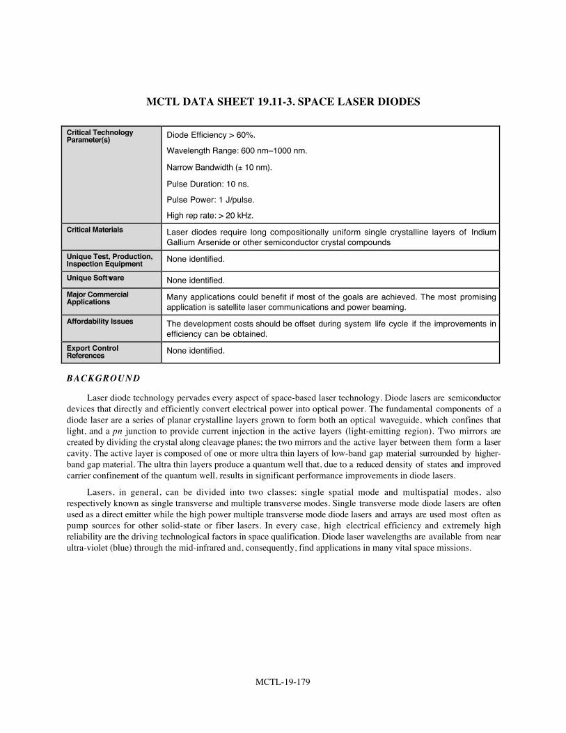
MCTL-19-179
MCTL DATA SHEET 19.11-3. SPACE LASER DIODES
Critical TechnologyParameter(s) Diode Efficiency > 60%.
Wavelength Range: 600 nm–1000 nm.
Narrow Bandwidth (± 10 nm).
Pulse Duration: 10 ns.
Pulse Power: 1 J/pulse.
High rep rate: > 20 kHz.Critical Materials Laser diodes require long compositionally uniform single crystalline layers of Indium
Gallium Arsenide or other semiconductor crystal compoundsUnique Test, Production,Inspection Equipment None identified.
Unique Software None identified.Major CommercialApplications Many applications could benefit if most of the goals are achieved. The most promising
application is satellite laser communications and power beaming.Affordability Issues The development costs should be offset during system life cycle if the improvements in
efficiency can be obtained.Export ControlReferences None identified.
BACKGROUND
Laser diode technology pervades every aspect of space-based laser technology. Diode lasers are semiconductordevices that directly and efficiently convert electrical power into optical power. The fundamental components of adiode laser are a series of planar crystalline layers grown to form both an optical waveguide, which confines thatlight, and a pn junction to provide current injection in the active layers (light-emitting region). Two mirrors arecreated by dividing the crystal along cleavage planes; the two mirrors and the active layer between them form a lasercavity. The active layer is composed of one or more ultra thin layers of low-band gap material surrounded by higher-band gap material. The ultra thin layers produce a quantum well that, due to a reduced density of states and improvedcarrier confinement of the quantum well, results in significant performance improvements in diode lasers.
Lasers, in general, can be divided into two classes: single spatial mode and multispatial modes, alsorespectively known as single transverse and multiple transverse modes. Single transverse mode diode lasers are oftenused as a direct emitter while the high power multiple transverse mode diode lasers and arrays are used most often aspump sources for other solid-state or fiber lasers. In every case, high electrical efficiency and extremely highreliability are the driving technological factors in space qualification. Diode laser wavelengths are available from nearultra-violet (blue) through the mid-infrared and, consequently, find applications in many vital space missions.

MCTL-19-181
SECTION 19.12—SPACE SYSTEMS ENGINEERING AND DESIGN TOOLS
CRITICAL ISSUES
Space Systems Engineering and the performance models and design tools required to perform the engineeringand modeling tasks to meet specific military requirements may need to be reviewed for military criticality on a caseby case basis.
BACKGROUND
There will be no formal data sheet for the Space System Engineering and Design Tools technology item sinceit is not defined or described in terms of quantifiable physical parameters. System Engineering is not unique to spacebut rather is a pervasive management method employed in almost all advanced technology development efforts.Because it is so pervasive and includes intellectual items rather than hardware items, System Engineering relateditems do not lend themselves to description or categorization methods used for hardware items. This means that extradiligence is required when determining if a System Engineering item is militarily critical or not. Particularly sowhen the System Engineering item is also space related because the United States currently enjoys a decidedsuperiority in space based systems and those systems may be particularly vulnerable.