Embed Size (px)
Citation preview
NOTE: MIL-STD-2193(SH) has been redesignated as a handbook, and is to be usedfor guidance only. This document is no longer to be cited as a requirement.For administrative expediency, the only physical change from MIL-STD-2193(SH) isthis cover page. If cited as a requirement, contractors may disregard therequirements of this document and interpret its contents only as guidance.
MIL-HDBK-2193(SH)21 June 1994_____SUPERSEDINGMIL-STD-2193A(SH)29 August 1991
AMSC N/A FSC 4810
DISTRIBUTION STATEMENT A. Approved for public release; distribution isunlimited.
NOT MEASUREMENTSENSITIVE
DEPARTMENT OF DEFENSEMILITARY HANDBOOK
HYDRAULIC SYSTEM COMPONENTS, SHIP
Downloaded from http://www.everyspec.com

MIL-STD-2193B(SH)21 June 1994
DEPARTMENT OF THE NAVYNAVAL SEA SYSTEMS COMMAND
Arlington, VA 22242-5160
Hydraulic System Components, Ship
1. This Military Standard is approved for use by the Naval Sea Systems Command,Department of the Navy, and is available for use by all Departments and Agenciesof the Department of Defense.
2. Beneficial comments (recommendations, additions, deletions) and any pertinentdata which mav be of use in imrovinz this document should be addressed to:Commander, Na~al Sea SysternsC&nand7 SSA 03R62, 2531 Jefferson Davis Hvy,Arlington, VA 22242-5160Improvement Proposal (DDletter.
by using the self-addressed Standardization DocumentForm 1426) appearing at the end of this document or by
ii
Downloaded from http://www.everyspec.com

mL-STD-2193B(SH)21 June 1994
FDRSWORD
This standard provides general requirements and test procedures for shiphydraulic system components. This standard does not establish configurationrequirements, pressure, flow or performance requirements for any specificcomponent. Such requirements will be identified in military and DoD componentspecifications and in component acquisition apecif icationa.
Downloaded from http://www.everyspec.com

Paragraph 1.1.11.21.3
2.2.12.1.12.22.3
3.
4.4.14.24.34.3.14.3.2
5.5.15.1.15.1.25.1.2.15.1.2.25.1.2.35.1.35.1.45.1.55.25.2.15.2.25.2.35.2.45.2.55.2.65.2.75.2.85.2.8.15.2.8.25.2.8.35.2.95.2.9.15.2.9.25.2.9.35.2.9.4
MIL-STD-2193B(SH)21 June 1994
CONTENTS
E22Se
SCOPE , PURPOSE AND IMFLSMENTATION GUIDANCE ............Scope ................................................Purpose ..............................................Implementation guidance’. .............................
REFERENCED DOCUMENTS ..................................Government documents .................................Specifications and standards .........................Other publications ...................................Order of precedence ..................................
DEFINITIONS ...........................................
GENERAL REQUIREMENTS ..................................Compatibility ........................................Materials ............................................Environmental conditions ........................... .Ambient pressure .....................................Ambient temperature ..................................
DETAILED REQUIREMENTS .................................Materials ............................................Metals ...............................................Plated coatings ......................................Cadmium and zinc plating.. ...........................Aluminum alloys ......................................Ferrous alloys .......................................Plastic parts ........................................Prohibited materials .................................Mercury contamination ............................. .Construction .........................................Standard parts .......................................Reverse installation .................................
Structural strength ..................................Weight ...............................................Surface roughness ....................................Alignment ............................................Orifices .......................................... .
Seals ................................................General ..............................................O-rings ..............................................Back-up rings ........................................Fasteners ............................ ................‘rhreadedinserts .....................................Bolt hole diameter ...................................Safety ...............................................Self -locking devices .................................
1111
11145
5
556666
666777777888888889999101010101010
iv
Downloaded from http://www.everyspec.com

MIL-sTD-2193B(SH)21 June 1994
CONTENTS - Continued
Jw.e
Paragraph 5.2.105.2.10.15.2.10.25.2.10.35.2.115.2.125.2.135.2.145.2.14.15.2.1.3.25.2.14.35.2.14 ..35.2.14.55.2.155.2.165.2.175.2.17.15.35.3.15.3.1.15.3.1.25.3.1.35.3.1.45.3.1.5S.3.1.65.3.1.75.3.1.85.3.25.3.35.3.3.15.3.3.25.3.3.35.3.3.45.3.3.55.3.3 .5.15.3.3 .5.25.3..i5.3.4.15.3.4.25.3.6.35.3.55.3.65.3.75.3.B5.3.95.3.105.3.11
Retainer rings ...................................... 10Load limitation ..................................... 11
Installation clearances and tolerances .............. 11Installation and removal ............................ 11
Spring pina ......................................... 11Function-adjustment screws .......................... 11
Bleeding andsampllng ................................ ~~Fluid connections ................................... 11
Bosses ........................................?..... 11Sxternal tube connections ........................... 11
Flanges ............................................. 12
Fluid connection mmrking ............................
Connector tubes ..................................... ::
Lubrication ......................................... 12Lifting and handling attachments .................... 12Identification of product ........................... 12
Harking ............................................. 12Test procedure ..................................... 12Test conditions ..................................... 12Adverse toleranr.e conditions ........................ 12tlinhum clearance specimen .......................... 13
Haximum clearance specimen .......................... 13
Tolerance considerations ............................ 13Temperature ......................................... 13Teat fluid and fluid teqeratire .................... 13Immersion ........................................... 13Paramatera measurement .............................. 1’4
Inspection routine .................................. 16
Teat methods ........................................ 16
operation ........................................... ~salt fog ............................................Proof pressure ......................................Burst preaaure ...................................... ::
Laakage tests ....................................... 16
External leakage ........ ...........................
Internal leakage .................................... ::~treme temperature functioning ..................... 16Low temperature ..................................... 16Intermediate temperature ............................ 17High temperature .................................... 17
Endurance ........................................... 17Fatigue .............................................. 17
Noise ............................................... 17
Vibration ........................................... lBReliability ......................................... 18Maintainability ..................................... 18Shock ............................................... 18
v
Downloaded from http://www.everyspec.com

MIL-sTD-2193B(SH)21 June 1994
I
CONTENTS - Continued
m
Paragraph 5.3.12 Contamination sensitivity ........................... 185.3.13 Component cleanliness ............................... 195.4 Drawing practices ................................... 19
6. NOTES ............................................... 196.1 Guidance for application of test requirements ....... 196.1.1 Components to military specifications ............... 196.1.2 Commercial components and components to shipbuilder
prepared specifications ............................ 196.2 Subject term (key word) listing ..................... 20
Table III
Figure 1
TABLES
Metal coatings ...................................... 7Inspection sequence ................................. 14
FIGURSS
Contamination sensitivity test circuit .............. 21
I
vi
Downloaded from http://www.everyspec.com

IIIL-STD-2193B(SH)21 June 1996
1. SCOPE, PURPOSE AND IMPLEMENTATION GUIDANCE
1.1 ~. TIIls standard provides general requirements that are common tomost components used in ship hydraulic (power trammission and control) systems.This standard does not establish conf fguration requirements, pressure, flow, orperformance requirements for any specific component.
1.2 ~. The purpose of this standard is to standardize the genaralrequirements, including testing, for hydraulic components used in shipboardhydraulic systerns. This standard also provides guidsnce as to when special designand test requirements, such es impulse fatigue, should be applied to shipboardhydraulic components. T?Iis standsrd will be used to provide the generalrequirements for a number of military specifications for ship hydrsulic componentsand as the basis for general requirements in specifications developed byshipbuilders and contractors for the acquis ition of ship hydraulic components.
1.3 ~. mare suitable fOr we. the s“lectfOn Ofcomponents shall be made in the following order:
(a) AC required by the applicable detail shipbuilding specification orother invoked contractual requirements.
(b) As identified in the hydraulic system sections of KIL-sTD-438 and141L-STD-777, ae applicable.
(c) In accordance with military and industry specifications andstandards with configuration control which meet the requirementsof this standard. Where no other guidsnce is available, SAE HRP6538 may ba used for selecting hydraulic directional controlvalves. Marine hydraulic system deeignera should also refer toSAE HIR 4564 for assistance in identifying specifications andscandsrds that are suitable for use in marine hydraulic systems.
(d) Configurations in accordance with ❑ilitary and industryspecifications. (Minor modification such es seal substitution to❑eet this atandsrd is acceptable. )
(e) Previously used components, modified if necessary, to comply withthis standard.
(f) Commercial components, modified as necessary, to comply with thisatandard.
(g) New components deeigned in accordance with this standsrd.
2. REFERENCED DOCUMSNTS
2.1.1 s and standards. The following specifications sndstandards form a part of this document to the extent specified herein. Unless
otherwise specified, the issues of these decuments are those listed in the DefenseIndex of Specifications and Scandnrds (DoDISS) and supplement thereto, cited inthe solicitation (see 6.2) .
Downloaded from http://www.everyspec.com
MIL-sTD-2193B(SH)21 June 1994
SPECIFICATIONS
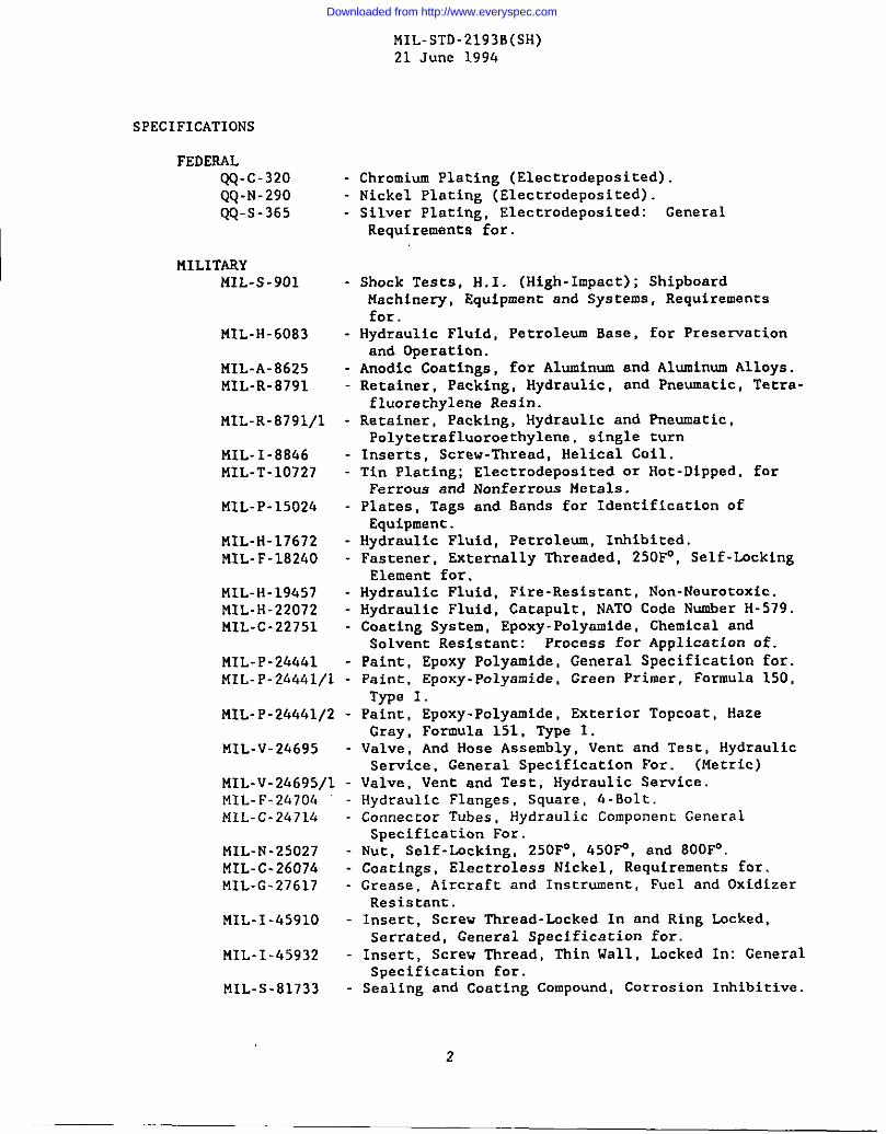
FEDERALQQ-c-320 - Chromium Plating (Electrodeposited).QQ-N-290 - Nickel Plating (Electrodeposited).QQ-S-365 - Silver Plating, Electrodeposited: General
Requirements for.
MILITARYMIL-S-901 - Shock Tests, H.1. (High-Impact); Shipboard
Machinery, Equipment and Systems, Requirementsfor.
MIL-H-6083 - Hydraulic Fluid, Petroleum Base, for Preservationand Operation.
MIL-A-8625 - Anodic Coatings, for Aluminum and Aluminum Alloys.MIL-R-8791 - Retainer, Packing, Hydraulic, and Pneumatic, Tetra-
fluorethylene Resin.MIL-R-8791/l - Retainer, Packing, Hydraulic and Pneumatic,
Polytetrafluoroethy lene, single turnMIL-I-8866 - Inserts, Screw-Thread, Helical Coil.MIL-T-10727 - Tin Plating; Electrodeposited or Hot-Dipped, for
Ferrous and Nonferrous Metals.MIL-P-15024 - Plates, Tags and Bands for Identification of
Equipment.MIL-H-17672 - Hydraulic Fluid, Petroleum, Inhibited.MIL-F-18240 - Fastener, Extermlly Threaded, 250F0, Self-bcking
Element for.MIL-H-19457 - Hydraulic Fluid, Fire-Resistant, Non-Neurotoxic.MIL-H-22072 - Hydraulic Pluid, Catapult, NATO Code Number H-579.MIL-C-22751 - Coating System, Epoxy-Polyamide, Chemical and
Solvent Resistant: Process for Application of.
MIL-P-244hl - Paint, Epoxy Polyamide, General Specification for.MIL- P-24441/l - Paint, Epoxy-Polyamide, Graen Primer, Formula 150,
Type 1.MIL- P-24441/2 - Paint, Epoxy-Polyamide, Exterior Topcoat, Haze
Gray, Formula 151, Type 1.MIL-V-24695 - Valve, And Hose Assembly, Vent and Test, Hydraulic
Service, General Specification For. (Metric)MIL-v-24695/l - Valve, Vent and Test, Hydraulic Service.MIL-F-24704 - Hydraulic Flanges, Square, 4-Bolt.MIL-C-24714 - Connector Tubes , Hydraulic Component General
Specification For.MIL-N-25027 - Nut, Self-Lacking, 250~, 450F”, and 800F”.MIL-C-26074 - Coatings, Electroless Nickel, Requirements for.MIL-G-27617 - Grease, Aircraft and Instrument, Puel and Oxidizer
Resistant.MIL-I-4591O - Insert, Screw Thread-Lacked In and Ring Locked,
Serrated, General Specification for.MIL-I-45932 - Insert, Screw Thread, Thin Wall, Locked In: General
Specification for.MIL-S-81733 - Sealing and Coating Compound, Corrosion Inhibitive.
2
Downloaded from http://www.everyspec.com

MIL-STD-2193B(SH)21 June 1994
MILITARY (Continued)HIL-R-832h8 -
UIL-K-832&8/l -
MIL-R-83268/2 -
MIL-R-83485 -
l!IL-R-83485/l -
MIL-C-83982 -
STANDARDS
MILITARYHIL-STO-1OO -HIL-STD-167-1 -
!IIL-STD-167-2 -
uIL-STD-&38 -
MIL-STD-7L0-1 -
UIL-STD-760-2 -
MIL-STD-785 -
HIL-STD-777 -
HIL-STO-81O -
NIL-STD-889 -MIL-STD-1251 -t’lIL-sTo-ls98 -fiIL-sTo-175b -
HIL-STD-1759 -
HIL-STD-1764 -IIIL-STD-1903 -!4s20995HS21344
Rubber, Fluorocarbon Elastomer, High Temperature,Fluid, and Compression Set Resistant.
Rubber, Fluorocarbon Elastomer, High Temperature,Fluid, and Compression Set Resistant, O-Rings,Clase 1, 75 Hardness.Rubber, Fluorocarbon Elastomer, High Temperature,Fluid, and Compression Set Resistant, O-Rings,Claes 2, 90 Hardness.Rubber, Fluorocarbon Elaatomer, Improved Per-formance at Low Temperature.
Rubber, Fluorocarbon Elaatomer, Improved (USAF)Performance of LrIwTempernturea, O-Rings, Sizesand Tolernncea.Compound, Sealing, Fluid Resistant.
Engineering Drawing Practices.t4echanical Vibrations of Shipboard Equipment(’fypeI - Environmental and ~e II InternallyExcited).
Mechanical Vibrations of Shipboard Equipment(Reciprocating Kachinery and Propulsion System andShafting) Types III, IV and V.Schedule of Piping, Valves, Fittings, andAssociated Piping Components for SubmarineService.
Airborne Sound Iieasurementa and Acceptance Criteriaof Shipboard Equipment.Stmctureborne Vibratory Acceleration Iieaaurementsand Acceptance Criteria of Shipboard Equipment.
Reliability Program for Syetema and EquipmentDevelopment and Production.
Schedule of Piping, Valves, Fittings, andAssociated Piping Components for Naval SurfaceShips .
Environmental Test l!ethodc and EngineeringGuidelines.Dissimilar Metals.Screws and Bolts Preferred for Oesign, Listing of.Studs Preferrad For Deeign, Listing of.Fastening Devices Preferred for Design, Listingof.
Rivets and Rivet Type fasteners Preferred forDesign, Listing of.
Washers Preferred for Oc.sign, Listing of.Nuts Preferred For Dasign, Listing of.Wire, Safety or Lock.Installation of Flared Tube,Connectors, Design Standard
3
Straight Threadedfor.
Downloaded from http://www.everyspec.com

MIL-STD-2193B(SH)21 June 1994
MILITARY (Continued)MS2f+391 - Plug-Bleeder, Tube Precision Type.MS33540 - Safety Wiring and Cotter Pinning, General Practices for.MS33547 - Pin, Spring, Functional Limitations of.
(Unless otherwise indicated, copies of federal and military specificationsand standards are available from the Standardization Documents Order Desk,Building 4D, 700 Robbins Avenue, Philadelphia, PA 19111-5094. )
2.2 Non-Government publication. The following documents form a part ofthis standard to the extent specified herein. Unless otherwise specified, the
issues of the documents which are DoD adopted are those listed in the issue of theDoDISS specified in the solicitation. Unless otherwise specified, the issues ofdocuments not listed in the DODISS are the iasuea of the documents cited in thesolicitation.
AMERICAN NATIONAL STANDARDS INSTITIITE (AXSI)B46 .1 - Surface Texture, Surface Roughness, Waviness and Lay.
(DoD adopted)Y32.10 - Graphic Symbols for Fluid Power Diagrams. (DoD adopted)
(Application for copies should be addressed to the American NationalStandards Institute, 1430 Broadway, New York, NY 10018.)
ANERICAN SOCIETY FOR TESTING AND i’!ATERIALS(ASTM)B 633 - Standard Specification for Electrodeposited Coatings of
zinc on Iron and Steel. (DoD adopted)
E 208 - Standard Method for Conducting Drop-Weight Test toDetermine Nil-Ductility Transition Temperature ofFerritic Steels.
F 303 - Standard Practicas for Ssmpling Aerospace Fluids FromComponents.
(Application for copies should be addressed to the American Society forTesting and Materials, 1916 Race Street, Philadelphia, pA 19103. )
NATIONAL FLUID POWER ASSOCIATION (NFPA)T2.6.1 -
T3.9.18 -
T2.12.2 -
T2,12.1O -
Method for VerifyLng the Fatigue and Establishing theBurst Pressure Ratings of the Pressure ContainingEnvelope of a Metal Fluid Power Component.
Method of Establishing the Flow Degradation of FixedDisplacement Hydraulic Fluid Power Pumps When Exposedto Particulate Contaminant.
Method of measuring average steady-state pressure.(DoD adopted)
Testing general measurement, principles and tolerances.(DoD adopted)
(Application for copies should ba addressed toAssociation, Inc. , 3333 N. Mayfair Road, Milwaukee,
the National Fluid PowerWI 53222.)
Downloaded from http://www.everyspec.com

MIL-sTD-2193B(SH)21 June 1994
SOCIETV OF AUTOMOTIVE. ENGINEERS (SAE)
J 514 - Hydraulic Tube Fittings. (DoD adopted)J 518 - Hydraulic Flanged Tube, Pipe, and Hose Comectiona,
f+-Bolt Split Flange.J 1926 - Straight Threads O-Ring Port.J 2244/1 - Connections for Fluid Power and General Use - Ports snd
Stud Ends with 1S0261 Threads and O-Ring Sealing Part1: Port with O-Ring Seal in Truncated Housing,Standard; December 1991 (1S06149- 1).
J 2244/2 - Connections for Fluid Power and Ceneral Use - Ports andStuds Ends with 1S0261 I%rends and O-Ring Sealing Part2: Heavy Duty (S Series) Stud Ends - Dimensions,Design, Test Methods, and Requlrenmnte, Standard;December 1991 (1S0 6149-2).
MA 2010 - Packing, Preformed - O-Ring Seal Standard Sizes & SizeCodas, Metric.
MA 2012 - Port Connection Internal, Straight ‘1’breed,tletrlc.MA 3352 - Packing, Preformed - O-Ring Seal, AUS 7276, Uecrfc.!4A3445 - Packing, Preformed O-Ring Seal, Fluorocarbon
(uIL-R-83485, &pe I), Metric.UAP 3b39 - O-Ring Groove Design for Packing Preformed, Elastomeric
O-Ring Seals, Static Axial Compression, Metric.UAP 34.30- O-Ring Groove Oesign for Packing Preformed, Elastomeric
O-Ring Seals, Static Radial Squeeze, Hetric.HRP 4538 - Selection of Hydrnulic Directional Control Valves For
Harine Vehicle Applications.HRP 4S44 - Specifications and Standards for Marine Hydraulic
Syeternsand Component.AS 568 - Aerospaca Size Standard For O-Rings.AS 4716 - Gland Daaign, O-Ring and Other Elastomeric Seals.
(Application for copies should be addreaaed to the Society of AutomotiveEngineers, 400 Commonwealth Drive, Warrendale, PA 15096.)
(Nongovernment atandarda are ganarslly available for rafarence fromIibrarfes. They are also distributed among nongovernmanc standarda bodies andusing Federal agenciea. )
2.3 Order of P recedence. In che event of a conflict between the text of
this standard and the references cited herein, the cexc of this standard shalltake precedanca.
I 3. DEFINITIONS
I Not applicable.
I 6. GENERAL R4UIREIKNTS
4.1 ~. Components ahnll be compatible with HIL-H-17672petroleum base, tiIL-H-22072 water-glycol, and MIL-H-19457 triaryl phosphate ester
hydraulic fluids. Component shall also be compacfble with preservation fluid inaccordance with MIL-H- 6083.
5
Downloaded from http://www.everyspec.com

MIL-sTD-2193B(SH)21 June 1994
4.2 Materials. Materials used in the manufacture of hydraulic componentsshall be compatible with the specified fluids and temperatures, and unlessotherwise specified in the component specification, shall conform to the
applicable reference documents cited herein. Material conforming to contractor’sspecifications may be used provided it can be demonstrated that they are at leastequivalent to the applicable military specifications and standards with respect toperformance characteristics.
4.3 environmental conditions. Unless otherwise specified by the componentspecification, components shall operate continuously in the environments specified
herein.
.4.3.1 Ambient uressurq. The components shall operate throughout an ambientpressure range of 8.25 x 10⁻¹ to 1.25 bars (12 to lB pounds per square inch(lb/inz)) absolute and shall operate to the requirements of this standard and the
applicable component specification.
4.3.2 Ambient temperature. Unless otherwise specified in the applicablecomponent specification, components shall operate throughout an ambient tem-perature range of minus 40 to 80 degrees Celsius (C), except components installedwithin heated spaces shall operate throughout a temperature range of 5 to 80”C.
5. DETAILED REQUIREMENTS
5.1 Hateri als.
5.1.1 Metals. Metals shall be compatible with the intended temperature,function, service, and storage conditions to which the components will be exposed.The metals shall possess corrosion-resistant characteristics or shall be protectedby anodizing or the use of coatings to resist corrosion which ❑ay result from suchconditions as dissimilar metal combinations, moisture, salt spray, and hightemperature deterioration, as applicable. Dissimilar metals are defined inMIL-STD -8B9. Low ductility material or high transition temperature ❑aterisl shallnot be used in pressure containing boundaries of components. (Control valveslides and sleeves are exempt where suitability is proven by high- impact shocktests. ) Low ductility material and high transition temperature material may beused in non-pressure boundary and non-load carrying applications where suitabilityis proven by high- impact shock tests. Low ductility material is metallic materialshowing less than 10 percent elongation in a standard tension test. Hightransition temperature material is material having a nil-ductility transitiontemperature (NDTT) above the minimum operational temperature. The NDTT shall beas measured by the drop-weight test in accordance with ASTM E 208. Charpy V-notchimpact values may be used as criteria when these have been correlated with drop-weight test results.
I
Downloaded from http://www.everyspec.com

NIL-sTD-2193B(SH)21 June 1996
TABLS 1. Metal
Coating Applicablespecification
Zinc plating ASIW B 633Chromium plating QQ-c-320Nickel placing QQ-N-290Silver plating QQ-S-365Tin plating MIL-T-10727, type IElectroless nickel HIL-c-26074
5.1.2 ~. Plated coetings and msteriels used in the componentehell be only these suiteble for the intended eervice and ehell be in accordancewith teble I or provide equivalent protection es determined by the contractingactivity. Where not indicated, class or type ie at the option of themanufacturer.
5.1.2.1 ~. Cadmium end zinc plating ehell not be
used for internml perte or on internal eurfaces in contact with hydraulic fluid.This restriction does not prohibit the use of zinc or cadmium-pletad standardparts such as nute, bolte, end ecrevs in locationa that are external to the syetemif there is no danger of fluid contamimstion.
5.1.2.2 ~. Aluminum elloys shall be anodized in accordancewith t41L-A-8625 and shall be resistent to stress corrosion cracking.
5.1.2.3 ~. Sstermal surfacee of ferrous alloys with a chromiumcontent of less than 12 percant shall be protected againat corrosion by the use ofone of the platinga or coatings listed in table I or by painting with a tvo-component syscem eposy -polyamide coating. The coating shall be in accordance withNIL-P-26461, HIL-P-2&fdJl/l (formula 150), t41L-P-24441/2 (formula 151) orllIL-C-22751.
5.1.3 ~. Synthetic materials for use as seals, guides, vipere,and so forth shall conform to the applicable specifications for these parta.Other nonmetallic parts may be used subject co the limitations of the applicabledetail specification when verified to be compatible with all fluids in accordancewith che immersion test of 5.3.1.7.
5-1.~ ~. The following materials shall not be usedunless epecificnlly permitted herein:
(a) Toxic materials.(b) Zinc or zinc plated materials (see 5.1.2.1).(c) Mercury (see 5.1.5).(d) Hmgnesium or msgneslum-base alloys.(e) Radioactive materials.(f) Asbestos.
Downloaded from http://www.everyspec.com

MIL-STD-2193B(SH)21 June 1994
(g) Catiium (see 5.1.2.1).(h) Beryllium (beryllium is acceptable as a small percentage (less than
3 percent) alloying material) .
5.1.5 &3rcurv contamin ation. The component or any component parts shall notcome in direct contact with mercury, mercury compounds or mercury bearinginstruments or devices employing only a single boundary of containment duringmanufacture, tests or inspections. No mercury or mercury bearing parts shall beinstalled or used in the component.
5.2 Construction.
5.2.1 Standard Parts. Standard parts (per approved government and industryspecifications and standards) shall be used whenever suitable for the purpose andshall be identified and numbered in accordance with the requirements ofDOD-STD-1OO. Where permitted by the component specification, commercial utilityparts, such as screws, bolts, nuts, and cotter pins may be used, provided theypossess equivalent properties and are replaceable by the standard parts withoutalteration, and provided that both the commercial parts and the correspondingstandsrd part numbers are included on the drawings required by the componentspecification. For standard commercial components this can be accomplished with across reference between commercial utility parts and standard parts.
5.2.2 Reverse installation. When internal parts can be reversed or rotatedand, as a consequence, the component is subject to malfunction, a method ofverifying proper assembly shall be provided. This ehall consist of a functionaltest which shall be identified on the component assembly drawing epecified in thecomponent specification, or by keying, directional arrow, indexing, or othermethod of identifying direction of installation.
5.2.3 ~h. The components shall withstand all loads orcombinations of loads resulting from hydraulic pressure, vibration, shock,temperature variations, actuation or operation, and torque loads for connection oftube fittings in accordance with MS21344.
5.2.4 -. System components shall be designed for minimum weightconsistent with the requirements of this standard.
5.2.5 Surface rouzhness. Surface roughness finishes for all moving andmating parts shall be identified in accordance with ANSI B46.1. The determinationof surface finishes shall be made with a prof ilometer, comparator brush analyzer,or other comparison equipment with an accuracy of plus or minus 15 percent at thelevel being measured. If surface defects are unacceptable, either allimperfections shall be within stated limits or special inspection procedures shallbe identified. Where a surface of 16-microinch roughness height rating or fineris specified, the process description shall be in addition to required surfacemeasurement. When necessary for assembly or proper operation, waviness and layshall be specified.
5.2.6accurately
Alienment. Plungers, poppets, balls, pistons and so forth, shall beguided to prevent misalignment or chattering.
8
Downloaded from http://www.everyspec.com

,. MIL-STD-2193B(SH)21 June 1994
I
I
5.2.7 ~. Where orifices less than 500 ❑icrometers in dicmecer areused internally in the componenc, the orifice shall be removable for systemflushing and shall be protected by a etrainer -type element. Orifices andstrainers shall withstand 110 percant of operating pressure, including no-flowconditions, without rupture. Strainers protecting the orifices shall haveopenings no lerger than 40 percent of the orifice diameter.
5.2.8 m.
5.2.8,1 ~. Sufficient clearance shall exiet to permit asaembly of thecomponents without dammge to O-rings or back-up rings where they pass threadedparts or sharp corners. lhe glands for O-rings, quad- type rings, and T-type ringsshall be in accordance with the following:
(a) For static.and dynamic sealing appllcatiom using SA8 AS568 sizeO-rings at pressures exceeding 100 bar (1450 lb/in2) utilizing oneor cvo anti-extrusion (backup) rings and application at pressuresunder 100 bar (1650 lb/in2) without backup rings, glands shall bein accordance with SAE AS 4716. The use of shallower depth glandsto increase squeeze ia permissible, where required, such as forface-type seala.
(b) For ❑etric size static radial seals up to 100 bar (1450 lb/inz)without backup rings, glands shall be in accordance with SAS MAP3440.
(c) For metric size dynamic radial scale in applications at pressuresexceeding 100 bar (1450 lb/in2) utilizing one or two anti-extrusion (backup) rings and applications at pressures undar 100bar (1450 lb/inz) without backuu rinxs. Elands shall be deeinedfor StU?,HA 2010 O-ring sizee in_acco~d&~e with the guidelin~s ofSAS AS 4716.
(d) For metric size face-type seala glands shall be in accordance withskisMAP3639.
(e) For etandard commercial components, the manufacturer’s standardglands may be used provided they do not require nomt.andsrd sizeseala. Similarly, for existing navy designs, the current sealglands are acceptable if they perform satisfactorily when standardsize seals are utilized.
T-type rings, quad rings, compression lip seals and other seals vhich can be usedin the standard glands identified above may be used where significant improvementover O-ring performance will be obtained. Usa of sanls which require glands otherthan those identified above shall be used only where standard seals will not meetperformance requirements.
5.2.B.2 ~. O-rings shall be fluorocarbon elastomer in accordance withUIL-R-8348S and HIL-R-83485/l or MIL-R-83268 and HIL-R-832b8/1, except 900 seriesdash numbers shall be in accordance with HIL-R-83248/2. O-rings in accordancewith MIL-R-83485/l are preferred where cemperntures below ❑inus &*C may beencountered. Uetric D-rings shall be in accordance with SAS KA 3645 or MA 3352.
I
Downloaded from http://www.everyspec.com
MIL-sTD-2193B(SH)21 June 1994
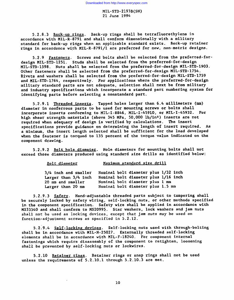
5.2.8.3 Back-uu rinm. Back-up rings shall be tetrafluorethylene inaccordance with MIL-R-8791 and shall conform dimensionally with a militarystandard for back-up rings when an applicable standard exists. Back-up retainer
rings in accordance wi,thMIL-R-8791/l are preferred fOr new, nOn-metric designs.
5.2.9 Fasteners. Screws and bolts shall be selected from the preferred-for-design MIL-sTD-1251. Studs shall be selected from the preferred-for-designMIL-sTD-1598. Nuts shall be selected from the preferred- for-design MIL-STD-1903.Other fasteners shall be selected from the preferred- for-design FSIL-STD-17S4.Rivets and washers shall be selected from the preferred-for-design I’41L-STD-1759and HIL-STD- 1764, respectively. For applications where the preferred- for-designmilitary standard parts are not adequate, selection shall next be from militaryand industry specifications which incorporate a standard part numbering system foridentifying parts before selecting a nonstandard part.
5.2.9.1 Threaded inserts. Tapped holes larger than 6.4 millimeters (mm)diameter in nonferrous parts to be used for mounting screws or bolts shallincorporate inserts conforming to MIL-I-8846, MIL-I-4591O, or MIL-I -45932. Forhigh shear strength materials (above 345 MPa, 50,000 lb/in~ ) inserts are notrequired when adequacy of design is verified by calculations. The insertspecifications provide guidance on determining the length of insert required. Asa minimum, the insert length selected shall be sufficient for the load developedwhen the fastener is torqued to 135 percent of the torque value indicated on thecomponent drawing.
5.2.9.2 Bolt hole diameter. Hole diameters for mounting bolts shall notexceed those diameters produced using standard size drills as identified below:
Bolt dfamete< Maximum standard size drill
3/6 inch and smaller Nominal bolt diamater plus 1/32 inchLarger than 3/4 inch Nominal bolt diameter PIU 1/16 inch20 mm and smaller Nominal bolt diameter plus 1 mmLarger than 20 mm Nominal bolt diameter plus 1.5 mm
5.2.9.3 -. Hand-adjustable threaded parts subject to tampering shallbe securely locked by safety wiring, self-locking nuts, or other methods specifiedin the component specification. Safety wire shall be applied in accordance withMS33540 and shall conform to MS20995. Star washers, lock washers and jam nutsshall not be used as locking devices, except that jam nuts may be used onfunction-adjustment screws as specified in 5.2.12.
5.2:9.4 Self-locking devices. Self-locking nuts used with through-boltingshall be in accordance with MIL-N-25027. Externally threaded self -lockingelements shall be in accordance with MIL-F-18240. For component internalfastenings which require disassembly of the component to retighten, looseningshall be prevented by self-locking nuts or lockwires.
5.2.10 Retainer rines. Retainer rings or snap rings shall not be usedunless the requirements of 5 .2.10.1 through 5.2.10.3 are ❑et.
10
Downloaded from http://www.everyspec.com

fiIL-STD-2193B(SH)21 June 1994
5.2.10.1 LwUMa&m. Wdr~ulfc. structural, mechanical, or any otherform of loads, or combinations thereof, including vibration, shock loada,expansion or contraction due to thermal changes, and eo forth, vhich may causeaxial displacement or failure of the ring, shall not be exerted on the ring.
5.2.10.2 ~. Re-~- ‘%s “r ‘“Prings shall not be used where buildup of clearances and manufacturing toleranceswill allow destructive end play in the assembly that may came, or contribute to,failure of packings or gaskets brinelling, or fatigue failure of parca.
5.2.10.3 ~. The retainer rings or snap rings shallbe installed and removad with standard pin-type pliers or other standard toolsdeveloped for uae vith the rings.
5.2.11 ~. Unless approved by the contracting activicy, springpins shall not be uaad in eny epplicationa that conflict with MS335fb7.
5.2.12 luscm~ w. EMnction-adjustment screws, if used,shall maintain adjuatmant under all tha required condltione of vibration, shock,temperature, end operetion. Friction- type locking devices shall be kept to aminimum and shall be subject to the approval of the contracting activity. Iffriction- type locking davicas are used, the adjustment screws shall maintain chairsetting after adjusting through the full range 15 times, or as specified in thecomponent specification, and then vibration taeced es apecif ied in 5.3.8. Theadjustment screws shall be adjuated and locked with a standard vrench orscrewdriver. Where practicable, the adjuacment screws shall adjuat undar fullsystem pressure with negligible loss of fluid. The means of adjustment shall beeither internal or protected from tampering by a cover or similar device.
5.2.13 ~, The configuration of components shallminimize the potential for air pockets; however, when raquired, provision shall bemade for bleeding of entrapped air. Auxiliary bleed ports shall be provided vhennecessary, and bleed plugs shall conform to tIS24391. Valvea in accordance withtiIL-v-26695/l may be used for bleeding and venting and shall be used vhere
Sqlhg of fluid ia required or where a pressure teat station is required.
5.2.14 ~. Fluid conneccione shall be static O-ring sealbosses, flanges, quills or O-ring union na listed in MIL-STO-638 or MIL-STO-777,as applicable. Pipe chreada shall not be used.
5.2.16.1 ~. Internally threaded bosses for connecting fittings andplugs shall conform r.oSAS J1926, scralght thread O-ring boss. Bosses shall bedeep enough, or ehall incorporate fittlng atopa, to prevent damage to internal❑echanism or restriction of fluid flow when universal fittings are screwed intothe bosses to excessive depths. Metric ports for straight thread comectionsshall conform to SAE MA 2012 or SAE J22U/1 .
5.2.lfJ.2 ~. External mala threaded tuba connection.ashall conform to SAE J514, SAE J2244/2 thread dimensions for mating with straightthread O-ring bosses.
11
Downloaded from http://www.everyspec.com

MIL-sTD-2193B(SH)21 June 1994
5.2.14.3 Flanges. Flanges shall conform to MIL-F-24704 or SAS J518 exceptthat other flanges identified in the applicable hydraulic sections of MIL-STD-438and MIL-sTD-777 or in component specifications referenced therein may also be usedwhen applicable.
5.2.14 ..+ F1 ufd connection marking. Ports shall be clearly and permanentlymarked to indicate the connections to be made using standard nomenclature. Whereapplicable, the direction of flow shall be indicated.
5.2.14.5 ~onnec tor tubes. Internal connecting tubes shall be in accordancewith a specification sheet to NIL-C-24714.
5.2.15 Lubrication. Unless otherwise specified by the acquisitionspecification, if lubrication is necessary during assembly, the lubricant shallconform to HIL-G-27617, type 111.
5.2.16 Liftine and handling attachments. Attachments for lifting eyes orhandles shall be provided when the weight of the component exceeds 23 kilograms(kg) (50 pounds) .
5.2.17 Identification of uroduc~. Each component shall be identified bymeans of a nameplate conforming to MIL-P -15024. A faying surface sealantconforming to UIL-C-83982 or MIL-S-81733 shall be used under mechanically fastenednameplates to prevent corrosion.
5.2.17.1 Markinp. A nameplate shall be installed on the component toidentify:
(a) Standard part number or specification number, if applicable,manufacturer’s name and part number.
(b) Fluid power symbol in accordance with ANSI Y32. 10. This is notrequired for small components whera compliance is not practical.
(c) Component operational data, if required by the componentspecification.
5.3 Xest Drocedures. The hydraulic component+ shall be tested in accordancewith the applicable component specification. The specific test proceduresidentified herein should be included as applicable in the component specification.(See 6.1)
5.3.1 Test conditions. The applicable test conditions shall be specified inthe component specification. If not addressed in the component specification, thefluid and temperature requirements herein shall apply.
5.3.1.1 Adverse tolerance conditions. l%e component shall function whenassembled with adverse tolerance parts without degradation in componentperformance or life. Unless otherwise specified in the applicable componentspecification, compliance to this requirement shall be made by either mathematical
analysis or by testing of ❑inimum and maximum clearance samples.
12
Downloaded from http://www.everyspec.com

FIIL-sTD-2193B(sH)21 June 199L
I
I
I
5.3.1.2 Minimum cle arance euecfm en. One specimen shall be assembled from
parts which have been selected to provide that the clearance with regard to linearand diametrical tolerances betveen moving and rxmunoving members, conducive comalfunctioning at extreme temperatures, will not exceed 110 percent of the minimumclearance. For sliding parts where packing friction will influence theperformance of the component, such as pistons operated by spring, the mcximumpacking friction shall be induced in the test epecimen. O-ring packing glandsshall provide maximum O-ring equeeze, including the effect of adverae O-ring crosssection tolerances. This specimen shall be marked “MIN=.
5.3.1.3 ~. The second specimen shall be assembledfrom perts which have been selected to provide that the clearance with regard tolinear and diametrical tolarancee betveen moving members, conducive tomalfunctioning as a rasult of wear associated with prolonged operation, will benot less than 90 percent of tha maximum clearance. This apacimen shall be marked“uAx” .
5.3.1.4 ~. In machining these specimens, surfacefinishee shell ba no finer than the surface ffniahas produced on production units.Where friction la not a factor, packing glands may be fabricated to nominaldimem ions. hpped or aelectlvaly fitted parts need not be made to adverselimits. In order to fabricate epecimene vith adverse tolerance, it ie permissibleco produce one of the mscing parts required with the critical clearance outside ofdrawing tolerances, provided that the clearance, as fabricated, falls within theestabllehed design range.
5.3.1.5 &mueratu~. Unless othervise specified herein or in the applicablecomponent specification, che tests shall be conducted at e room temperature of 15to 30*C.
I
5.3.1.6 ~. Unlese otherwise specified hereinor in the applicable component specification, the fluid used for pressure droptests shall be in accordance with t41L-H-17672, 2135-T-H. Pressure drop endleaksge tests shall be conducted with the fluid ec 40SC.
5.3.1.7 ~. This test shall be conducted on all nonmetallic mte -rials not specifically identified in this standard which racybe in concact withthe fluid or fluid leakage for which ahrinkege or ewelling could affecc per-formsnce. Smch material shall be subject to an immersion test in each of thefollowing fluids:
(a) Uater(b) ML-H-17672, 2135-TH(C) 141L-H-22072(d) ML-H-19457
Critical dimensions shall be measured before immereion and after immersion for 7dsys at 70 * 2*C. Material subject to shrinksge or swelling shall not be usedunless additional testing established that the shrinkage or swelling does notaffeet performance or operability. As a minimum, the additional testing shallinclude subjecting the material in the assembled component to the fluid causingthe most adverae effact for a period of 7 days at 70 i 2°C prior to conducting
13
Downloaded from http://www.everyspec.com

MIL-STD-2193B(SH)21 June 1994
first article or qualification tests. After the immersion at elevated tempera-ture, the equipment shall remain in the fluid at room temperature until just priorto testing. Flushing of the immersion fluid just prior to an operational testwill be permitted. The internal parts shall not be exposed to air for any
appreciable length of time until operability and performance is verified.
5.3.1.g Parameters measurement. ‘fhemeasurement of average steady-statepressure for first article/qualification testing shall be in accordance withANSI/ (NFPA) T2 .12.1. Unless othervise specified herein or in applicable componentspecification, the level of accuracy in test parameters measurements for firstarticle/qualification testing shall be in accordance with Glass B of ANSI/ (NFPA)T.12.1O.
5.3.2 Znsuection routine. ‘Ihecomponent specification shall identify the
required inspections and tests using the guidsnce herein for their selection.Unless otherwise specified in the applicable component specification, a singlesample unit shall be subjected to the inspection and tests specified in table 11.The recommended test sequence shall be as specified in table II. Qualityconformance tests and requirements shall be as specified in the componentspecification.
TABLE II. Inspection seauence.
Tests
salt fogProof pressureExternal leakageInternal leakageExtreme temperatureShockVibrationEnduranceReliabilityMaintainabilityContaminationsensitivity
FatigueNoiseBurst pressure
5.3.3 Test methods.
Test paragraph
5.3.3.25.3.3.35.3.3 .5.15.3.3 .5.25.3.45.3.115,3.85.3.55,3.95.3.105.3.12
5.3.65.3.75.3.3.4
5.3.3.1 09eration. Each component shall be subjected to at least 10 normaloperating cycles at the rated pressure specified In the applicable componentspecification without any sign of external leakage or other malfunction.
Downloaded from http://www.everyspec.com

FIIL-sTD-2193B(SH)21 June 1996
I
I
5.3.3.2 ~lt fog. Unless othervise specified in the component specifica-
tion, the components shall be subjected to the salt fog test procedures specifiedin MIL-STO-81O, method 509.2 for L8 hours. After completion of testing andcleaning, the base metal of the component shall not be visible through the coatingor finish, nor shall there be any evidence of blistering, softening, separationfrom the base metal corrosion producte, or other coacing failures. When more th~one design h developed by the same contractor who uses the same method of surfacepreservation for 811 designs, only one repreeentativa unit shall require thistest, provided the ssme materials are used. Unless otherwise specified in thecomponent specification, test data on similar equipment with the same base andcoating materials and equivalent coating thickness msy be used co meet thisrequirement.
5.3.3.3 ~. Unless otherwise specified in tha applicablecomponent specification, a proof pmseure of 150 percent of the syetem retedoperating pressure shall be applied to the components. The rated operatingpressure of a component 1s the msximum safe operating or working pressure based onan established number of fatigue cyclee and does not preclude uae in applicationsaubject to infrequent higher cransimt pressures. For parta nat covered by aspecification or standard, che contracting activity shall specify the requiredproof pressure. The following additioml guidance shall be used in dstarminingthe minimum proof pressure:
(a) Suction ports. At leaat 135 percent of the maximum suctionpressure, but not less than 2 bars (29 lb/inI).
(b) Pmsaure and cylinder ports. Xhe proof pressure shall net be lessthan the max5.ss.uscalculated pressure developed under conditions ofhydraulic shock considering, buc noc necessarily limited to, suchfactora as rapid valve closing, overhauling and suddenly appliedloads, and relief valve full flow setrings and response time.
(c) Return ports. At least 13S percent of the msxhum calculatedreturn line pressure considering maximum flow rates snd minimumfluid temperatures. If a stop valve ie installed in a returnline, the requirements for pressure and cylinder porca shall also
apply upstream of the stop valve and the proof preaaure must be atI least equsl to that developed with full flow through any reliefvalve protecting the return line.
For unbalanced cylinders and other componc.nte subjected to pressure multiplica-tion, the proof pressure for ports subjecred to pressure multiplication shall be
not less than the nomlnsl system pressure times che mulciplicar.ion factor based onarea ratios.
5.3.3.b Burst messurq. The burst pressure shall be as specified in thecomponent epecificntion and shall not be leas than 250% of the rated operatingpressure. Components containing air or gas under pressure shall be subject to aburst preswre of at least 400X of the oparacing pressure. In addition, theminimum burst pressure shall not be less than 150X of the proof pressure. Thecomponent shall not rupture under this praaaura. The pressure may be increasedabove that specified in order to secure data on actual rupture pressure. Ifrequired, this shall be the lust teat performed because of its destmcttve nature.Components that require different test pressures in differenK elemanta shall have
15
Downloaded from http://www.everyspec.com

MIL-sTD-2193B(SH)21 June 1994
these pressures applied either separately or simultaneously, whichever is the ❑ostcritical. Components that are subject to pressure in the reverse direction suchas check valves, shut-off valves, or accumulators shall be pressurized in bothdirections either separately or simultaneously, whichever is most adverse. Theburst pressure test is not required if the specified component is subjected to thefatigue test specified in 5.3.6.
5.3.3.5 Lsakaee tests.
5.3.3 .5.1 External leakage. During the course of all of the tests specifiedin this standsrd (with the exception of shock, endurance, and fatigue) , externslleakage, other than a slight wetting insufficient to form a drop through staticseals, shall be cause for rejection. Where external, dynamic seals are utilized,permissible leakage past such seals shall be not greater than that specified inthe applicable component specification. During shock and endurance testing,allovable leakage shall not exceed that specified in the component specification.
5.3.3 .5.2 ~n temal leakaee. Unless otherwise specified in the componentspecification, internsl leakage tests shall be conducted by applying 0.35 bar(5 lb/in2), 50 percent of rated operating pressure, and operating pressure in thepositions identified below:
(a) Valves. Lsakage tests shall be conducted for all positions inwhich the valve blocks flow.
(b) Cylinders, actuators. Leakage tests shall be conducted at the twoend positions of travel.
(c) Other components. Laakage tests shall be conducted with componentheld in the position most conducive to leakage.
The leakage measurement shall begin within 2 minutes after the application ofpressure and shall be measured for not less than 1 minute nor more than 10minutes. The rates of leaksge shall not exceed those specified in the componentspecification. Quality conformance (acceptance) tests shall be the same asdescribed shove, except tests need be conducted only at rated operating pressures,except when first article (or qualification) tests have indicated that leakage atother conditions is greater.
5.3.4 Extreme temperature functioning. When this test is specified in theapplicable component specification, it shall be conducted as follows:
5.3.6.1 Low temwrature. The component shall be connected to the ratedoperating pressure specified in the applicable component specification. Unlessothervise specified in the applicable component specification, this.arrangementshall be maintained at a temperature not warmer than minus 40”C for 3 hours afterthe temperature has stabilized at ❑inus 40-C. After this period, the componentshall be actuated at least two times. Variation of actuating forces or regula-tion, as applicable, shall not exceed that specified in the component specifi-cation. The leakage tests in 5.3.3.5:1 and 5.3.3 .5,2 shall be performed aftereach actuation to determine conformance to the requirements of the applicablecomponent specification. Use of low viscosity fluids will be permitted duringthis test.
16
Downloaded from http://www.everyspec.com
liIL-STD-2193B(SH)21 June 199fJ
5.3.4.2 ~termediate tcmmerature. Unlese otherwise specified in the
applicable component specification, immediately following the low temperature test
(see 5.3.6. 1), the test arrangement shall be warmed rapidly to 80*C. While thetemperature is being raised, the component shall be actuated at maximum incrementsof 15*C to determine satisfactory operation throughout the temperature range.These tests shall be performed without waiting for the temperature of the entirecomponent to stabilize.
5.3.6.3 ~. The component shall be maintained at 80”c for alength of time sufficient to S11OW all parta to attain this temperature. Thecomponent shall then be actuated at least tvo times. In tha cane of praaaureactuation or regulation, the variation of actuating forces or regulation shall notaxcaed that spacified in the applicable component specification. Tha leakage test(see 5.3.3.5. 2) ahnll be performed after each actuation and tha Iaakagarequirements of the applicable component specification shall be met.
5.3.5 Endur.m~. Components shall be designed for a 30-yaar service lifewhich may be equated to 150,000 hours of operation. Compliance with the servicelife requirement shall be damonetrated for components noc subject to qualificationor first articla taating undar a military specification. Unlass otharvisespecified in tha acquisition apacification, this shall be done either by a firstarticle cyclic operation enduranca test or baaed on data rapraaenting at laaat 5years of continuous oparar.ing experience. Unless otharwiae specifiad, thaendurance test can be limited to 2,000,000 cycles or 500 hours oparating time forcentinuously operating componenca and other components where tascing for themumber of cycles equivalent co 30 years oparacion is impractical. During chaendurance test, individual parts carriad on board for logistic aupporc, such asseala, may be replaced ac intervals equivalent to not laaa than 20,000 hours or200,000 cyclaa of operation, whichever la leas. Disposable type filter elements
in components may be replacad when required. AC che conclua ion of the endurancetaac, the componenc shall oparata aacisfactorf Iy and meat endurance performancerequlrementa specified in che applicable componant specification. If specificendurance requirements are not specified in the componenc specification, then anfntermal leakage test shall be conducted and the leakaga shall not exceed 300percent of that specif lad for a new component.
5.3.6 ~. Valves, pressure containers, and similar componenca (excepc
hose assembliaa) which have an expected servica life of one million or morepressure cyclee, with a magnitude in excess of 50 percent of thair rated operatingpressure, shall be fatigue tested co 90 percent assurance and 90 percentconfidence levels Ln accar&nce with NFPA T2.6.1.
5.3.7 m. When tested in accordance with MIL-STD- 740-1 andliIL-sTD-740-2, the component shall perform in accordance vith the requirementsspecified in che applicable component specification. The noise test shall beeither airborne or structurebome as spacified in the npplicabla componentspecification. The noise test shall be performed after all ocher tests have beencompleted, vich che exception of che burst pressure C13SC.
L7
Downloaded from http://www.everyspec.com

..
MIL-sTD-2193B(SH)21 June 1994
5.3.8 Vibration. Components shall operate when subjected to type I(environmental vibration) vibration tests in accordance with MIL-STD -167-1. Inaddition rotating machinery such as pumps and motors, shall meet the type 11(internally excited vibration) requirements of MIL-STD -167-2. For type I teststhe component shall be tested in each on three mutually perpendicular axes.However, if a component is symmetrical about a principal axis, vibration testingneed only be accomplished along two orthogonal axes, one of which shall be theprincipal axis of symmetry. The vibration test shall be run early in thecomponent test program or various tests repeated after vibration testing to assurethat vibration has not had an adverse effect on performance. .%nyof the followingconditions resulting from vibration are considered unacceptable:
(a) Damage to parts(b) Loosening of parts(c) Degradation of operational performance (including leakage) below
specification requirement.
5.3.9 Reliability. When specified in the component specification, eachcomponent shall meet a specified quantitative reliability requirement in terms ofmean- time-between failure (KTBF) or its equivalent. Reliability tests shalldemonstrate conformance with the reliability requirements and confidence factorsas specified in the applicable component specification for critical components (asdefined in FIIL-STD-785).
5.3.10 )laintai.nabilitY. The component shall demons trate the ability tomeet the allowed time for maintenance actions identified in the componentspecification. The elapsed time and man-hours required to replace each of the onboard repair parts and the elapsed time and man-hours to perform each proposedprevent ive maintenance task shsll be recorded. The average cumulative number ofhours per week needed to perform both preventive and corrective maintenance tssksshall not exceed the requirements of the applicable component specification.Fault correction time for corrective maintenance tasks and servicing time forpreventive maintenance tasks shall be recorded separately.
5.3.11 -. The components shall perform as specified herein and in the
applicable component specification after being subjected to the high impact shocktest, grade A, class I as specified in NIL-S- 901. The components shall be cycledafter each blow during the test to determine that no damage has occurred as aresult of the impact. A momentary interruption of the component function duringshock testing shall not be interpreted as a failure. Post shock test inspectionshall include all functional and operational tests to demonstrate that thespecified requirements are met.
5.3.12 ~y. When required by the componentspecification, the components shall meet the requirements of the applicablecomponent specification when subjected to a contamination sensitivity test inaccordance with NFPA T3.9.18 or other procedure approved by the Naval Sea SystemCommand (see 6.1.2(d)). The test circuit shall be modified by the addition of acomponent test loop as shown on figure 2.
18
Downloaded from http://www.everyspec.com

?41L-sTD-2193B(sH)21 June 1996
5.3.13 Colnoonenc clea~. Component cleanliness levels shall be as
identified in the procurement specification. Where the procurement specificationinvokes this ❑ilitary standard but does not identify a specific cleanliness level,the fluid sampled from the component shall not exceed the following particlecounca:
es ner 100 a
Greater than 15 ❑icrometres 14,000Greater than 25 mlcrometres 2,500
Greater than 50 micrometres 400
Unless otheruiae specified, the above counts apply to samples taken in accordancewith practice A of ASTM F303.
5..3 we in. .reeticeg Engineering drawing practices for hydrauliccomponent dra~ings shall be” in accordance with MIL-STD-1OO.
6. NfYT2S
6.1 Q&dance for a~ of t et re~.e
6.1.1 ~. ~En a c“~”n’nt “ procuredto military specification, the tests in this standard apply only to the extentidentified in the component military specification.
6.1.2 $O~ercial cO~onencs and cOm~ tO Milder or-~. Every teat need not be applied to each component. Tha procuringactivity has the respomibility for determining if any of the tests may be daletedbased on the following guidance:
(a) For standard commercial components being used within the applicabledesign parameters, i.e. pressure, temperature, speed, environment,etc. the testa for adverse tolerance and extreme temperaturefunctioning are not required.
(b) Reliability and maincainabillty requiremancs need be included inthe component specification only when required by the shipbuildingor other higher level specification.
(c) High impact shock requirements need not be applied if thecomponents are used solely in a system not subject to theserequirements.
(d) The contamination sensitivity test may be limited KO those electro-hydraulic servo valves, electric driven motors and hydraulic pumpsnot in accordance with a ❑ilitary or industry specification listedin the 00DISS. A contamination sensitivity test procedure forvalves 1s being dovelopad by the National Fluid Power Association.However, concaminnnt sensltivicy test procedures do not specifyfnil/paae criteria. Accordingly, the fnil/pasa criteria mat bespecified in the procurement specification. (NAVSEA 031J16 shouldbe consulted regarding contamination sensitivity test proceduresand pass/fail criteria. )
(e) For some tests, guidance on the applicability of the teat isidentified in the test procedure.
19
Downloaded from http://www.everyspec.com
,. . . ,..
MIL-STD-2193B(SH)21 June 1994
6.2 Subiect term (kev word) listing.
Adverse tolerance conditionsCadmium plateContamination sensitivityHydraulic systerncomponentsZinc plate
Preparing activity:Navy - SH(Project 481O-N1O8)
20
Downloaded from http://www.everyspec.com

MIL-STD-2193B(SH)21 June 1994
—
RESERVOIR
~FLOH CONTROL-(1F REOUIRED)
PUMP
SAMPLE VALVE
INJECTIONCHAXBER
FLOH METER
FIGURE 1. COn tomination sensitlVitv test circui.&.
21
Downloaded from http://www.everyspec.com

I
I
I
I
I
I
STANDARDIZATION DOCUMENT IMPROVEMENT PROPOSAL
INSTRUCTIONS
1. The preparing activity must complete blocks 1.2, 3. and 8. In block 1, both the document number and revisionletter should be given.
2. The submitter of this form must complete blocks 4.5,6,and 7.
3. The preparing am”vity must provide a reply within 30 days from receipt of the form.
NOTE: This form may not be used to request copies of documents, nor to request waivers, or clarification ofrequirements on current contracts. Comments submitted on this form do not constitute or imply authorization towaive any portion of the referenced document(s) or to amend contractual requirements.
I RECOMMEND A CHANGE: ‘“ ‘%”~~~~f43B(SH)1.~~1~~ (YYMMLVLS)
“N%-%;cmsES2P23 COMF13NENIS, SHIP
.NATUREOF CNANGE (khtify pwaerati #wmb@f ●d Indtfdu WOPOW mwh if POESM. AEEX!I ●rtra s&b ●s needed)
. REASON FOR RECOMME?40AnOf4
L SUBMITTER
.mbsaaa% rtm. mwatnwl b. 0RGAM2AVSON
moum CndvG+ ZIP Cad.e) d. TELEPHONE Cnducfe Area Cd) 7. 06VE wawvvm
(1) command (vwL&fool
(2) AUTOVONflf ,ppficati)
. P6WAAENG ACTMTV
. NAME b, TELEPHONE (Inch& -a Code)Co2QsAms?x (i) Cemmercic.{ (2) AUTOVON
NAVAL WA SYS?31MS COMANO (SEA 03R42) (703) 602-9137 DSE6@32-9 137
AOORSSS- Zi code2!31 JES%EEtS&N DAVIS NW
1?YOU 00 NOT RECUVE A REPLY WllHIN 45 OAVS. CONTA~
ARLINS3’ON,VA 22242-5160Oefensa QualiEy ●nd Stmdadizacion Office5203 Ledwg Pike. Suite 1603. falls Church. VA 2206 t-3466Telephone (703) 756.2340 ALJTOVON 269.2360
Is c...... ,“.. nm . . -.”,-. .. 4,. L.- . . . ..l._ -,--- IUmu w.!!! .-s4”. “s, -> ., ...”., -.,”. ” .,. ,..,?W..,..
Downloaded from http://www.everyspec.com