Embed Size (px)
Citation preview

~
MIL-P-24344C(SH)2 Januarv 1991SUPERSEDINGMIL-P-24344B(SH)28 April 1975(See 6.11)
MILITARY SPECIFICATION
PRODUCER, LIQUID OXYGEN AND LIQUID NITROGEN(SHIPBOARD TYPE – LOW PRESSURE)
This specification is approved for use by the Naval Sea Systerrr$Command, Depatimentof the Navy, and is available foz use by all departments and agencies of theDepartment of Defense.
1. Scorl?
1.1 Scope. This specification covers a shipboard equipment which will produce liquid oxygenand liquid nitrogen by means of a low pressure air liquefaction and separation process. Only oneclassification of producer is covered.
2. AppLIcABLf3 DocuMEfws
2.1 Government docnments.
2.1.1 Specifications, stmrdards, smd handbooks. The following specifications, standards, andhandbooks form a part of this document to the extend specified herein. Unless otherwise specified,the issues of these documents are those listed in the issue of the Department of Defense Indexof Specifications and Standards (DODISS) and supplement thereto, cited in the solicitation (see6.2).
Beneficialcomments(recommendations,additions,deletions)and anypertinentdata whichmayk of use inimprovingthis dceumcnt should ix addressedto Commander,NavalSea SystemsCommand,SEA 55Z3,Departmentof the Navy,Washington,DC 20362-5101by usingthe self-addressedStandardizationDcummentImprovementProposal(DD Form 1426)appearingat the end of this decumentor hy letter.
AMSC NIA FSC 3655
DISTRIBUTION STATf3MfZNf?A. Approved for public release, distribution is unlimited.
Downloaded from http://www.everyspec.com

I““---””-”””””-
MIL-P-24344C(SH)
SPECIFICATIONS
I
I
I1’I
FEDERAL
BB-N-411
MILITARY
MIL-C-104
MIL-T-704
MIL-S-901
MIL-E-917
MIL-C-2212
MIL-P-15024
MIL-P-15024/5
MIL-E-15090
DOD-P-15328
MIL-S-16032
MIL-G-18997
MIL-V-22549
MIL-H-22S77
MFL-P-24441
MIL-L-25567
MIL-O-2721O
MIL-C-52211
Nitrogen, Technical
Crates, Wood: Lumber and Plywood Sheathed, Nailed and Bolted
Treatment and Painting of Materiel
Shock Tests, HI (High Impact), Shipboard Machinery, Equipmentand Systems, Requirements for
Electric Power Equipment, Basic Requirements (Naval ShipboardUse)
Controllers, Electric Motor AC or DC and Associated SwitchingDevices
Plates, Tags and Bands for Identification of Equipment
Plates, Identification
Enamel, Equipment, Light-Gray (Formula No. 111)
Primer (Wash), Pretreatment (Formula No. 117 for Metals);(Metric)
Switches and Detectors, Shipboard Board Afarm Systems
Gauge, Pressure, Dial Indicating
Valves, Angle, Relief, for Gas and Oxygen Service (Sizes 2-InchesIPS and Below), Naval Shipboard
Heating Elements, Electrical: Cartridge, Strip and Tubular Type
Paint, Epoxy-Polyamide, General Specification for
Leak Detection Compound, Oxygen System$ (Metric)
Oxygen, Aviator’s Breathing, Liquid and Gas
Components and Assemblies for Industrial Gas Production, Storageand Transport Equipment, Packaging of
2
Downloaded from http://www.everyspec.com
MIL-P-24344C(SH)
STANDARDS
MILITARY
MIL-STD-167-1
MIL-STD-278
MIL-STD-461
MIL-STD-462
- MIL-STD471
MIL-STE-740-1
MIL-STD-777
MIL-STD-781
MIL-STD-882
MIL-STD-889
MIISTD-1186
MIL-STD-1330
Mechanical Vibrations of Shipboard Equipment (Type I –Environmental and Type 11 – Internally Excited)
Welding and Casting Standard
Electromagnetic Emission and Susceptibility Requirements for theControl of Electromagnetic Interference
Electromagnetic interference Characteristics, Measurement of
Maintainability Verification Demonstration/Evaluation MIL-STD-740-lAirborne Sound Measurements and Acceptance Criteria ofShipboard Equipment
Airborne Sound Measurements and Acceptance Criteriaof Shipboard Equipment
Schedule of Piping, Valves, Fittings, and Associated PipingComponents for Naval Surface Ships
Reliability Testing for Engineering Development, Qualification, andProduction
System Safety Program Requirements
Dissimilar Metals
Cushioning, Anchoring, Bracing, Blocking and Waterproofingwith Appropriate Test Methods
Cleaning and Testing of Shipboard Oxygen, Nitrogen and HydrogenGas Piping Systems
(Unless otherwise indicated, copies of federal and military specifications, standards, and handbooksare available from the Standardization Documents Order Desk, Building 4D, 700 Robbirrs Avenue,Philadelphia, PA 19111-5094.)
2.1.2 Other Government documents, drawings, and publicrrtions. The following otherGovernment documents, drawings, and publications form a part of this document to the extentspecified herein. Unless otherwise specified, the issues are those cited in the solicitation.
DRAWINGS
NAVAL SEA SYSTEMS COMMAND (NAVSEA)
810-1385850 Piping, Gage for Afl Service
3
.
Downloaded from http://www.everyspec.com
MIL-P-24344C(SH)
(Application for copies should be wkfressed to the Commander, Portsmouth Naval Shipyard, NavalEngineering Drawing Support Aclivi[y, Code 202.2, Portsmouth, NH 038045000.)
PUBLICATIONS
NAVSEA
0900-LP-O01-7000 Fabrication and Inspection of Brazed Piping Systems
(Application for copies should be addressed to the Standardization Documents Order Desk,Building 4D, 700 Robbins Avenue, Philadelphia, PA 19111-5094.)
2.2 Non-Government pnblicrrtimrs. The following document(s) form a part of this documentto the extent specitied herein. Unless otherwise specified, the issues of the documents which areDOD adopted are those fisted in the issue of the DODISS cited in the solicitation. Unlessotherwise specified, the issues of documents not listed in the DODISS are the issues of thedocrrments citedin thesolicitatioq (see 6.2).
AMERICAN NATIONAL STANDARDS INSTfTUTE, INC. (ANSI)
B31 Code for Pressure Piping
(Application for copies should be addressed to the American National Standards Institute, 1430Broadway, New York, NY 10W8.)
AMERICAN SOCIETY OF MECHANICAL ENGINEERS (ASME)
Boiler and Pressure Vessel Code Rules of Construction of Pressure VesselsSection VIII
(Application for cnpies should be addressed to the American Society of Mechanical Engineers,345 East 47th Street, New York, NY 10017.)
AMERICAN SOCIETY FOR TESTING AND MATERIALS (ASTM)
D3951 Standard Practice for Commercial PackagingF1 166 Human Engineering Design Criteria for Marine Systems and Equipment; (DOD
adopted)
(Application for copies should be addressed to the American Society for Testing and MateriaIs,1916 Race Street, Pbiladelphta, PA 19103.)
(Non-Govemment standards and other publications are normally available from the organizationsthat prepare or distribute the documents. These documents also may be available in or throughlibraries or other informational services.)
4
Downloaded from http://www.everyspec.com
MIL-P-24344C(SH)
2.3 Order of precedence. In the event of a conflict between the text of this document andthe references cited herein, the text of this document takes precedence. Nothing in this document,however, supersedes applicable laws and regulations unless a specific exemption has been obtained.
3. REQUIREMENTS
3.1 General requirements. The producer shall receive compressed air and separate it intoliquid oxygen and liquid nitrogen at minus 312 degrees Fahrenheit (T) (minus 191 degrees Celsius(“C)) and 5 and 50 pounds per square inch (lb/inz) gauge minimum respectively.
3.2 First article. When specified (see 6.2), a sample shall be subjected to first articleinspection (see 6.5) in accordance with 4.3.
33 G&reral characteristics. The equipment shall be constructed for maximum reliability, andshall be operated, maintained, and repaired by personnel with a minimum of training. Theequipment shall assure rapidity, safety, ease and economy of maintenance in normal, adverse andemergency maintenance environments. The producer shall be fail-safe, so that any component orequipment failure will not cause operator injury or damage to other components. In addition, theproducer shall include automatic fail-safe controls to preclude equipment damage. The producershall perform its functions in an ambient compartment temperature of 122 “F (150 “C) minimum.The producer shall reflect efficient arrangement of operation and maintenance workplaces,equipment, controls, and displays to ensure efficient task performance. Equipment shall provide foradequate physical, visual, auditory, and other communication links between personnel and theequipment under both normal and emergency conditions. Controls, displays, marking, coding,labeling, and arrangement schemes (equipment and panel layout) shall be uniform for commonfunctions of all equipment. Where off-the-shelf equipment requires modification in order tointerface with other equipment, the modification shall conform to the criteria contained in thestandard. Detailed human engineering guidance covering the foregoing requirements are specifiedin ASTM F1 166. The producer shall be constructed in accordance with the human engineeringcriteria of ASTM F1 166 (see 6.3 and appendixes ~ B, and F).
33.1 Installation. The producer shall be configured for installation in a shipboardcompartment. After the producer has been manually started and product flow established, theproducer operation shall be fully automated to maintain full-rated production. Producer operationsincluding start-ups and shut-downs shall require only one operator. The maximum clearance neededaround the producer for maintenance or operation shall be not greater than 3 feet. Manual controlvalves and indicators (pressure gauges, temperature gauges, tachometers, and so forth) shall bemounted on a single face of the producer. Visual displays and controls shall be in aeeordanee withASTM 1166. The manual enntrols and control indicators shall be arranged so that the indicatorsare readable from the control position. Generally, th~ shall require that the indicator be within 3feet of the applicable control device. Removable panels shall be provided for quick and convenientaccess to the reversing valves, check valves, the turbo-expander, the producer vessel space,adsorbent filters, and for any other items which may require frequent maintenance attention (see6.3 and appendm C).
5
Downloaded from http://www.everyspec.com
MIL-P-24344C(SH)
3.4 Operating cycle. Air shall be supplied to the producer from a separate centrifugal aircompressor, via an after cooler. Immediately after the air enters the producer it shall pass througha moisture separator to remove entrained liquid. A reversing type heat exchanger shall be used tocool the process air and remove water and carbon dioxide. A contaminant removal system shall heused to remove traces of moisture, carbon dioxide and hydrocarbons which may remain in the coldprocess air stream from the heat exchanger. The effluent from the removal system shall be splitinto two streams; one stream shall flnw to a turbo-expander and the other stream to the distillationcolumns. The turbo-expander shall supply the refrigeration necessary to achieve liquefaction andseparation of air and shall be self-contained in the cold box, non-lubricated, and closed-loop airloaded. The effluent from the turbo-expander shall flow through a superheater-liquefier and to thereversing heat exchanger to cool down the incoming process air. The fraction of the process airto the distillation columns shall flow via the superheater-liquefier (for heat exchange with theturbo-expander effluent) to a high pressure column (nitr6gen column) or to a vapor-liquidseparator “and a low pressure column (oxygen column). Movement of process fluids shall he bydifferential pressure or by bubble-type pumps.
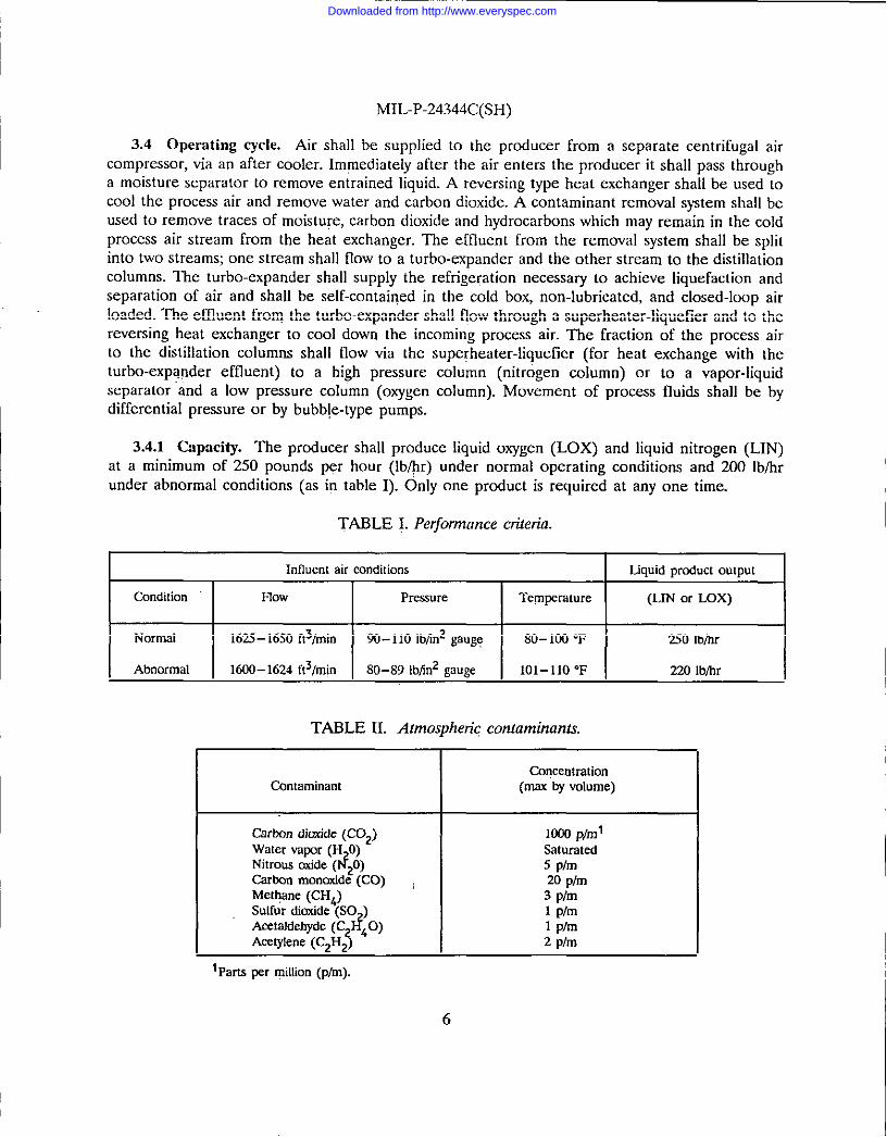
3.4.1 Capacity. The producer shall produce liquid oxygen (LOX) and liquid nitrogen (LIN)at a minimum of 250 pounds per hour (lb/@) under normal operating conditions and 200 lb/hrunder abnormal conditions (as in table I). Only one product is required at any one time.
TABLE I. Performance criteria.
Influentair conditions Liquidprnductoutput
Condition Frow Pressure Tem~rature (LIN or LOX)
Normal 1625-16S0ft3/min 90-110 lbfm2gauge 80-100 “F 250 lb~r
Abnormal 16W- 1624ft3/m@ 80–89 lbfin2gauge 101-110 “F 220 lb~r
TABLE IL Atmospheric contaminants,
ConcentrationContaminant (maxby volume)
Carton dioxide(C02) 1000p/mlWatervapor(H O)
P?Saturated
Nitroustide( ~0) 5 plmCarbnnmonaxide(CO) , 20 plmMet@tne(CH4) 3 plmSulfurdinxide(SO ) 1 plmAcetaldebyde(C#O)Acetylene(C2H$ 4
1 plm2 plm
lParts per rniltion(p/m).
6
Downloaded from http://www.everyspec.com

MIL-P-24344C(SH)
3.4.2 I’rrrity. ~eprodLicer shall producc oWgenwhich meets thepurity requirements of MIL-O-27210 type IIand nitrogen which meets thcpurity requirements of BB-N-411, t~e II, grade B,at the quantities specified in 3.4.1 when the inffuent air contains all of the contaminants in theconcentrations indicated in table H. Under conditions specified berein the producer shall operatecontinuously for a minimum of 720 hours before shutdown for defrost and before regeneration ofany adsorption bed. The producer shall be capable, immediately after completion of a720 hour run(cold plant), of being regenerated and defrosted and then operated so as to produce at specifiedrates and purities for additional 720 hour periods. The total time for shut-down, regeneration anddefrost, and resumption of production shall not exceed 24 hours.
3.5 Utilities.
3.5.1 Electricsd power. The producer shall require only one source of electric power. Theelectric p&ver supply shall be440 volts, 3-phase, 60 hertz (Hz). The mrrximum power demand rateof the producer shall not exceed 100 kilowatts (kW). The average power demand shalI not exceed75 kW. One main circuit breaker for the producer will be furnished by the installing activity.Other breakers or overloads shall be furnished with the producer and integrally mounted withintheequipment. Shipboard installed wiring shall be kept to a minimum. Wiring and instrumentationshall be installed, prewired, and prepipedon the producer. Ifelectric power ofother characteristicsis required, all equipment needed for the conversion shall be furnished as part of the producer.Control power shall be obtained from the main input power of tbe producer. Types of power otherthan electrical shall not be used.
3.5.2 Air. The producer shall require only one source of process air. Air shall be receivedfrom a separately installed centrifugal air compressor at the conditions specified in3.4.l. If airisrequired for operation of control valves or other equipment, the air shall be taken from theprocess air. Necessary equipment forcontrol ofairpressrrres shall beprotided with the producer.
3.5.3 Purge gas. ~eproducer cold boxenclosure shall beprasurized to at least 2 inches ofwater pressure with gaseous nitrogen. The maximum purge gas flow rate required to maintain thispressure shall not exceed 40 standard cubic feet per hour (ft3/h).
3.5.4 Water. The producer shall not require water.
3.6 Dimensions and weight. The producer envelope dimensions shall not exceed thefollowing: heighti 108inches, width (across front): 144inches and depth (front to back): 10Sinches. Total producer weight shall not exceed 20,000 pounds.
3.7 Shock rmd vibrotion. The producer shall meet the shock requirements of MHA3-901,grade ~ class I, deck-mounted equipment and the vibration requirements of MILSfT1-167-1, type1, frequency range 4 to 50 Hz Structural supports shall have no local resonances in the range from4t050 Hz.
Downloaded from http://www.everyspec.com

MIL-P-24344C(SH)
3.8 Pitch, mll,mrrfl istconditions. ~eproducer shall operate under specificd pitch, roll, andlist conditions when the largest (not diagonal) dimension of the producers parallel with the foreand aft centerline of the ship.
3.8.1 Operation at rated capacity mrd purity. The producer shall operate at rated capacityand purity under the following conditions:
a. Pitch – 4 degrees for an n-second periodb. Roll – 15 degrees for a 17-second periodc. List – 2.5 degrees.
3.8.2 Operation under increased list conditions. When operating at a list of 5.0 degrees toeither side, the producer shall produce liquid oxygen or nitrogen at a minimum of 75 percent ofrated capacity while maintaining minimum product purity levels specified in 3.4.2.
3.8.3 LOSSof fluids or damage. The producer shall not lose fluids or be damaged under thefollowing conditions:
a. Operating at a fried incline of up to 15 degrees in any direction
b, operating while pitching at a maximum of 10 degrees up or down from its normalhorizontal plane
c. Operating while rollinga maximum of 30 degrees toeither side of vertical.
3.9 Electromagnetic interferences. Unless otherwise specified herein, the producer shallconform to the electromagnetic emission requirements of parts 1 and 5 of MIL-STD-461.
3.10 Nnise. Total produced airborne noise levels shall not exceed 80 decibels (dB) at anyfreqrrenq when measured in accordance with MIL-STD-740-1. To conform to this requirement, theturbo-expander air load shall be closed-loop and muffled.
3.11 Thermal insulation. Surfaces, including the insulation jacket (see 3.14.6) except theouter end of sample Iinesand sample vaporizers, shall be so insulated that the surfaces will neithercollect frost nor sweat when exposed toanatmosphere with ad~bulb temperature of90”F (32.2‘C) and a wet bulb temperature of 80 ‘F (26.7 ‘C). Surfaces, the temperature of which may exceed120”F(49”C) during normal operation shall be insulated so that the resulting insulation surfacetemperature is below 120 “F (49 “C). Hydraulic setting types of insulation material shall not beused.
Either solid formed shapes, solid block type, or fibrous mineral blanket or loose fill typeinsulation shall be used. Fibrous mineral type insulation is permitted only as described in 3.14.6for producer cold box. The solid formed shape and solid block type insulation shall not have friablefibers, produce dust, or contain asbestos, silica, or any other materiai which w“lI cause lungdisorders. Insulation material shall be non-flammable in temperatures up to 572 “F (300 “C). Whenburning, theinsulation material shall not give offanytoxic gas. The insulation manufacturer shall
8
Downloaded from http://www.everyspec.com
MIL-P-24344C(SH)
certify that his insulation material conforms to the aforementioned flammability and toxicityrequirements. The insulation material shall conform to the chemical requirements of appendix H.The hydrocarbon oil content of the insulation shall not exceed 0.175 percent by weight.
3.12 Electrical equipment. Electric equipment andwiring shall be in accordance with MlL-E-917.
3.12.1 Controllers. Controllers shall eonformto MIL-C-2212 and the following
Voltage rating and phase –Duty —
Type —
Ins+dation .
Operation —
Performance —
Enclosures —
Protection features –
440volh,3~phase, 60HzContinuousAs requiredClass B, except that coils may be class AMagneticAutomatic with automatic shut-downDrip-proof or watertightThermal overload relay or low voltage protection or both foreach service. Protection feature shall be justified by thefailure mode and effects analysis (FMEA) (see 6.3). TheFMEA shall consider the maximum potential flow andPressure from the compressor and the flows through safetyvalves and associated upstream and downstream pressure.
3.12.2 Wiring. Electrical and thermocouple wiring shall be clearly labeled and run throughwire harnesses or conduit. Where possible, wiring and harnesses shall be run along tubing, pipingor structural members for support and protection.
3.12.3 Electrical insrdntiosr resistmrce. With the exception of thermocouples, eachindependent electric circuit shall have a resistance to ground and to other independent circuitsgreater than5 megohars (see 4.7.4).
3.13 Materials and fabrication.
3.13.1 Materisds. Welding andassociated inspections shall beinacmrdan@ tith MIL-S~-278. Materiafs used within the 02N2 producer shall be suitable for the intended me. piPing, PiPingcomponents, valves and process vessefs shall be constructed for a 125 pounds per square inchgauge (lbfin2) minimum pressure andatemperature range ofminu32O0F(minw 196”C)to 300“F (149 “C) for the maximum outlet temperature from the heater, whichever is higher. Designpressure and design temperature of pressure vessels and piping maybe reduced to a Iower valuebut not less than 25 Ib/inz and 2S ‘F greater than the most severe conditions of coincidenttemperature and pressure based on the condition of at least two indeperrdent failures includingoperator error during all phases of producer operation including start-up, shutdown, and defrost.Unless otherwise specified (see 6.2), thematerials wedshall delimited tothe3M seri=mrrosion-resisting steels, aluminum and aluminum alloys, copper and copper alloys, silicon-bronze, 70-30brass, or monel. Pressure vessels fabricated and of the materials as specified herein, shall be
9
Downloaded from http://www.everyspec.com

MIL-P-24344C(SH)
inspected in accordance with either ASMEBPVC, section VfII or the requirements of MIL-STD-278 for A-3 pressure vessels. Radiography ofclosure wekfsof A-3 pressure vessels is not required.Piping fabricated in accordance with MIL-STE-278 of the materials specified herein shall requirearadiographic sample of at least 10 percent of all butt-welded joints in lieu of the radiography testspecified hy MIL-STD278 for class P-LT piping. Carbon steel alloys may be used for structuralsupports which are not subjected to low temperature from cryogenic vessels or piping. The use ofdissimilar materials shall be minimized to preclude galvanic corrosion and shall he in accordancewith MIL-STD-889 requirements for selection and protection of dissimilar metals. Materialsincluding gaskets and valve packing shall be compatible with R-n and R-113 cleaning solvents.Any materials subject to corrosion shall be treated to prevent corrosion. Vessels subject tocorrosion shall include adequate corrosion allowance to insure a 20 year life. Afuminum shall behard anodized after all welding and forming has been completed on the component or pipingassembly. Component or piping material shall be selected ‘to minimize dissimilar metal joints.Where dii~milar metal joints are used, the joint construction shall preclude metal-to-metal contactand moisture entrapment at the gasket. Within the producer insulation jacket, each piping lineshall be separated by a minimum of 4 inches (measured radially frorp the closest point on thepiping surface) from any item ofdissimi!ar material.
3.13.1.1 Recovered materials. Unless otherwise specified herein, all equipment, material, andarticles incorporated in the. products covered by this specification shall be new and may befabricated using materials produced from recovered materials to the maximum extent practicablewithout jeopardizing the intended use. The term “recovered materials” means materials which havebeen collected or recovered frorq solid waste and reprocessed to become a source of raw materials,as opposed to virgin raw materials. None of the above shall be interpreted to mean that the useofusedor rebuilt products is allow&dunderthis speci~cation unless othetise specifically specified.
3.13.2 Brazing. Brazing of ferrous and non-ferrous piping shall conform to the requirementsof NAVSEA0900.LP-001 -7WI0. No equipment shall be fabricated by riveting or soft soldering.
3.133 Pneumatic testing. Pneumatic testing may be substituted for hydrostatic testingspecified in NAVSEA0900-LP-001 -7000, provided such testing and the method of lead detectionareclearly specitiedon the manufacturer’s drawing. Pneumatic pressure testing for pressure vesseland piping integrity shall be performed at I-lE times maximum working pressure. Leak testingshall be performed at a pressure not less than the maximum working pre.wure.
3.13.4 Pressrrre vessel mrd piping construction. Piping for fluids listed in MIL-STD-777 shallconform to MfL-STD-777 unless otherwise approved. Tapered pipe threads will not be permitted.Pres.sure containing vessels shall be in accordance with the ASMEBPVC section VIII for unfiredpressure vessefs MIL-STD-278. Piping and tubing shall be in accordance with ANSI B31 andwelding shall be in accordance with ASME BPVC section VIII or MILS.TD-278.
3.13.5 Piping, valves, and fittings.. Unless otherwise specified herein, all valves and fittingsshall be in accordance with MIL-STD-777. Valves and allmechanical joints shall beef the soft seatdesign. Relief valves shallbe union ended to facilitate removal fortesting and calibration. Pipingshall be configured to facilitate solvent cleaning and testing. There shall be no dead-ended piping.
10
Downloaded from http://www.everyspec.com
MIL-P-24344C(SH)
One-half inch inner diameter (id) tubing or below shall be bundled oraffwed to stronger membersforsupport, temperature profile permitting. Bonded transition joints will not bepermitted. Mereit is necessary to join dissimilar materials, flanges with cryogenic compatible gaskets shall be used.Valve packing, gasket, and O-ring materials shall be compatible with cryogenic fluids as well as R-11 and R-113 cleaning solvents. Mechanical joints within the producer cold box shall be kept toa minimum.
3.13.6 Components. Whenever possible, producer pressure boundary component shall bemade of type 300 series corrosion resisting steel or silicon bronze. Components shall be constructedfor a working pressure of 125 lb/in2 minimum.
3.13.7 Pressure vessels. Pressure vessels shall be made of type 300 series corrosion resistin5steel or silicon bronze. Pressure vessels shall be constructed for a working prexsure of 125 lb/in
minimum.
3.14 Producer. The producer shall consist of air drying and purification equipment, heatexchangers, distillation apparatus, turbo-expander, inlet air filter, silencers, an insulating jacket coldbox provided with necessary operating instrumentation and controls integrally mounted, and othernecessary components. A turbo-expander shall provide all refrigeration and cooling needed toproduce the required amounts of oxygen or nitrogen. A tachometer, readout device, and overspeedshut-down shall be provided for the turbo-expander. No motor driven pumps or compressors shallbe used in the producer. Oxygen clean pressure, liquid level, and flow instruments shall maintainthe required level of accuracy for continued plant operation without recalibration during a 5-yearperiod and a means shall he provided to verify the accuracy of the instruments withoutdisconnecting the instrument piping.
3.14.1 Stsrrt-up time. After the air flow is started to it the producer shall produce at fullrated capacity (see table I) within 12 hours of start-up at an ambient temperature of 122 “F (50“C) minimum and within 2 hours after a shut-down of 2 hourx.
3.14.2 Air drying turd purification. Air drying and purification system shall be w that neitherproducer defroxt nor adsorbent regeneration is required more frequently than every 720 hours.Equipment shall be provided to remove compressor lubricant, water, carbon dioxide, hydroearfxrns,and other contaminants as necessary to ensure acceptable product purity, as specified whenproeesxing air containing the contaminants specified in table II. In addition to the above air dryingand purification equipment, a secondary adsorption bed shall’ be provided to precludecontamination enrichment in the distillation columns. This secondary adsorption bed shall beexternal to the columns and the bed column shall be based on 0.003 cubic feet minimum perequivalent standard cubic feet per minute (ft3/min) of flow to the distillation columns. Consumablechemicals shall not be used for contaminant removal. The purification equipment and thesecondary adsorption bed shalI be regenerated using a process gas which contains less than 22volume percent oxygen. The process gas for regeneration shall be a by-product of the airseparation process.
11
Downloaded from http://www.everyspec.com

MIL-P-24344C(SH)II 3.14.2.1 Electric thaw heater. Electric heaters required [or heating gas for regeneration and
thaw of the producer shall conform to MIL-H-22577, type III, with a corrosion-resisting steel ornickel-chromium-iron alloy sheath. The outlet gas temperature from the heaters shall beautomatically controlled and heater burnout protection shall be provided. The warm air exhaustI
I from the turbo-expander may be used to preheat the feed gas to the heaters. Adsorbent bedregeneration heaters shall heat beds to a minimum temperature of 400 “F. The total time toregenerate each adsorbent bed shall not exceed 6 hours, with a maximum heating cycle of 2 hours.Thaw heaters shall warm the producer piping and vessels to a minimum temperature of 125 “F.Thaw heaters shaO be sized so that total producer thaw time does not exceed 12 hours.
3.14.3 Control valves. Valves shall be in accordance with MIL-STD-777 and as specifiedherein. For valves requiring fine adjustment, the handwheel shall indicate the degree to which thevalve is opened. Gate valves shall not be used in any throttling service. Valves shall havereplaceable seats and discs.
3.14.4 Automatic shut-off and safety valves. Electrically operated automatic shut-off valvesshall be furnished with tbe 02N2 producer at the compressed air inlet and at the turbc-expanderinlet for emergeney shut-downs. The separation process shall be protected from abnormal pressuresby safety valves. Safety valves shall be located in one region to facilitate inspection and shall beequipped with flanged or union type outlets connected to a single vent header. Safety valves shallconform to MIL-V-22549 or be approved by NAVSEA.
3.14.5 Pressure surd temperature switches. Pressure and temperature switches shall meet therequirements of MIL-S-16032 with respect to size, type, and application.
3.14.6 Insrrkstion jacket (cold box). Separation equipment operating at temperatures below32 “F (O ‘C) shall be enclosed in a jacket fabricated with a structural-metal frame and sheet-metalpanels. Other components of the producer shall be mounted on tbe same baseplate outside theinsulation jacket. The panels shall be easily removable, and no welding or cutting is to be requiredfor access for maintenance of the enclosed equipment including the replacement of heatexchangers and ecdumns. Instruments for control of the encl~ed equipment shall be mounted ona panel in front of the jacket. The entire jacket shall have sufficient insulation and thermalisolation of structural members to prevent the formation of frost spots when temperature andhumidity conditions are as speci~ed in 3.11. The insulation shall function and be as specified in3.11. The cold box insulation shall be solid block type insulating material except that mineral woolmay be used within the” interior and packed amid the process vessels and piping. Solid blockinsulation shall be used to the maximum depth possible in from the cold box exterior panels onall four sides and top and bottom. The block insulation shall be used around all maintainablecomponents and in the way of the access from the cold box exterior to those components. Thecold box shall be constructed so that during operation and during shut-downs there shall be a smallcontinuous flow of nitrogen purge gas, 40 standard cubic feet per hour (ft3/lrr) (maximum), fromthe center of the cold box toward the outside for the purpose of excluding entry of moisture.Piping, rotometers, and valves shall be provided for both nitrogen purge gas tapped from the airseparation process and nitrogen purge gas from an external source. The jacket shall be constructedto prevent any leakage in excess of 40 ft3/frr maximum at 2 inches of water pressure.
12
Downloaded from http://www.everyspec.com
MIL-P-24344C(SH)
3.14.7 Parity analyzers. One nitrogen and oxygen product purity analyzer and one waste gasanalyzer shall be provided with the producer. Analyzers shall be Sybron Corporation model numberX54OAA1O1O1-1 (517B) or equal and mounted on the producer. Product nitrogen, oxygen, andwaste gas sample lines shall be run from the columns via two-stage pressure regulators to theanalyzers. Sample gases are to be at room temperature prior to being sent to the analyzers. Theelectronic analyzers shall provide continuous readout of the purities. The electronic analyzers shallbe accurate to within O t 0.5 volume percent of the actual sample gas purity. The analyzers shallbe attached to the producer. The producer shall have sample gas tubing, calibration gas tubing, gasflow manifolds, and electrical wiring so that the purity of the sampled process stream can be easilyand accurately determined. The electronic analyzers shall have a warm-up period of 2 hoursmaximum, shall not require calibration more often than once in 24 hours, and shall not requireconsumables. If calibration gas is required for the electronic analyzer operation, the analyzers shall
Operate a! specified herein utilizing either milita~ gas (see 6.6) Or g= for which certifiedcomposition analysis is not necessacy. The analyzer shall not require calibration gas purity to bemore than 99.99 percent.
3.14.8 Liquid product sampling. Means shall be provided for drawing samples of the liquid
Oxygen product and liquid nitrogen product for analysis by means other than the electronicanalyzer. The sample lines shall be warmed in such a manner that the sample comes from theproducer as a gas and correctly represents the composition of the fluid being sampled. A liquidoxygen sample valve shall be provided for obtaining liquid samples to monitor the product oxygenin the oxygen column.
3.14.9 Liquid traps. ArIy line which carries liquid oxygen or liquid nitrogen from the producershall include traps in the line which prevent liquid from being in contact with the line’s valve whenthe valve is closed.
3.15 Instrumentation. Instrumentation shall be mounted on a common panel located at thefront of the producer, at between 4 and 6 feet from the base. Like instrumentation shall beclustered together along with applicable control devices.
3.15.1 Mechmsical.
3.15.1.1 Pressure grmges. Pressure gauges shall be in accordance with MIL-G-18997 forOxygen setice. Gauges shall be installed in accordance with Drawing 810-1385850 and mountedon a common instrumentation panel located at the front of the producer. Snubbers shall be usedto protect gauges. Dedicatecl gauges shall be provided to measure, as a minimum, the followingcritical pressures
a. Process air to cold box
b. Air from adsorbers
c. Air to adsorbers
d. Air to turbo-expander
13
Downloaded from http://www.everyspec.com

MIL-P-24344C(SH)
e. Air [rem turbo-expander
f. Low pressure column
g. High pressure column
h. Low pressure column condenser/reboiler (if operated at different pressures than highand low columns
i. Waste gas from columns
j. Waste gas to reversing heat exchanger
k. Defrost air to low temperature section
1. Seal air to expander.
3.15.1.2 Flowmeters. Flowmeters shall be differential pressure type, employing a rupture-proof bellows design. Meters will read in inches of water and shall be accurate to within plus orminus 4 percent of actual flow measurements. Graduations shall be black on a white background.Normal operating readings shall be indicated within the middle one-third range of the indicator.A graph which provides a means to determine actual flows based on the type of fluid beingmeasured and the temperature and pressure of the fluids shall be provided for each flowmeter.Tbe flowmeters shall be installed on a common instrumentation panel and measure, as a minimum,the following critical flows
a. Process air to reversing beat exchangerb. Unbalance stream air to reversing heat exchangerc. Afl process flow to all columnsd. Defrost air flowe. Regeneration gas flow.
3.15.1S Liquid level indicators. Liquid level indicators employing a rupture-proof bellowsdesign shal~ be provided to measure the process ffuid levels. The scale of each liquid level indicatorshall be equipped with a zero adjustment and shall be graduated in increments of water.Graduations shall be black on a white background. Normal operating readings should be indicatedwithin the middle one-thkd range of the indicators. Indicators shall be mounted on a commoninstrumentation panel at the front of the producer. Loop seals will be used to prevent flow in thelower gauge Iine. Dedicated indicators shall measure, as a minimum, the following critical levels
a. Crude oxygen in high pressure columnb. Crude oxygen in condenser and reboilerc. Liquid in column feed separatord. Liquid oxygen in low pressure column.
14
—.
Downloaded from http://www.everyspec.com
MIL-P-24344C(SH)
3.15.2 Electronic.
3.15.2.1 Temperature indicating system. A temperature indicating system shall be providedwith the producer. The system shall consist of individually installed resistance temperature detectors(RTD’s) which are connected to one common temperature indicating unit mounted on the frontof the producer. The temperature indicating unit shall have a digital readout and a rotary switchwith a position for each RTD installed. The system shall indicate a temperature at the followingpoints in the producec
:
c.d.e.f.
&h.i.
j.k.1.m.n.0.
P.
Entering airMain heat exchanger, air – inMain heat exchanger, air – out
. Main heat exchanger, waste gas - inMain heat exchanger, waste gas – outTurbo-expander inletTurbo-expander outletLow pressure distillation column topHeat exchanger inlet and outlet streamsColumn inlet and outlet streamsThaw heater inlet and outlet streamsLow pressure distillation column reboilerHigh pressure column condenserHigh pressure column feedProduct temperaturesSuperheater-liquefier, all flows in and out.
Temperatures c., d., f., and g. shall also be monitored separately from the others by a temperatureindicating system accurate to within plus or minus 1 “F at the normal operating temperatures. Atleast three of these temperatures shall be continuously monitored and indicated by the readout
system. On producers with an adjustable side bleed system, the main heat exchanger side bleedtemperature shall have a continuous monitor and readout and shall also be recorded on a datalogger. Each RTD and its piping well shall be immersed in the fluid stream.
3.16 Product filter. A product filter with adequate aeeess for maintenance shall be providedto prevent any carryover of the producer’s absorbents. The filter shall be within the insulatedportion of the producer cold box.
3.17 Outlet connections. Producer outlet connections from the producer shall be located inthe front of the producer at approximately 8 feet from the base and 6 to 8 inches from the leftside. The outlet connections shall be so that all shipboard interconnecting piping can be easilyconnected and any needed insulating material can be readily applied. No automatic valves, switches,or sensors associated with producer operation shall be required for the interconnecting piping.
15
Downloaded from http://www.everyspec.com

MIL-P-24344C(SH)
3.18 Irrterchmrfyrbility. In no case shall parts be physically interchangeable or reversibleunless such parts are aiso interchangeable or reversible with regard to function, performance, andstrength.
3.19 Plates and placards.
3.19.1 Identification and information plates. Identification and information plates shall be inaccordance with type A or B (plates of phenolic compounds will not be aeeeptable) of MILP-15024 and MIL-P-1 5024/5. Plates shall be attached with corrosion resistant screws, bolts, or rivetsin conspicuous locations. Arr identification plate shall be attached to each producer. Identificationplates which name the components to facilitate operation, shall be attached adjacent to or on eachvalve, pressure switch, liquid-level gauge, flowmeter, temperature gauge, pressure indicator, controlswitch, indjcator lamp, safety valve, and sample line. The component names (and alpha-numericdesignatioris, if used) on the plates shall be consistent with those used in the documentation (see3.3 and appendix B).
3.19.2 Information plates, shall be provided which will illustrate the following
a. A flow diagram of each individual process of the plant (for example, air refrigeration,air separation, reactivation gas flow) and the overall producer process
b. Electrical wiring schematic diagram of each individual circuit (for example, producerprocess monitors and controls) and the overall producer circuitry.
The plates for individual processes and circuits shall be attached near the appropriate controls andindicators. The plates for overall producer process and circuitry shall be attached to the front ofthe producer.
3.20 Lifting eyes. The producer shall have four lifting eyes to permit lifting by one overheadhoist.
3.21 Painting. External, exposed metal surfaces of the producer shall be painted, exeeptsurfaces such as valve extensions, identification plates, or surfaces which may be exposed totemperatures below minus 40 “F (minus 40 “C) in normal service. Metal surfaces of the stmcture,framework, and panels internal [o the co[d box shall be painted. Prior to painting, all fabricatingoperations, such as welding, machining, drilling, and tapping, shall be completed. Surfacepreparation and painting shall be accomplished in accordance with MIL-T-704 and as follows:
a. Remove all flrrx, loose mill scale, rust, and other visible corrosion products
b. Remove all grease, oil, and dirt by solvent wiping, vapor decreasing, caustic washingand rinsing, or other appropriate method
16
Downloaded from http://www.everyspec.com

MIL-P-24344C(SH)
c. Apply one coat of’wash-priming pretreatment, conforming to DOD-P-1532S, plus twocoats of semi-gloss light-gray enamel, conforming to MIL-E-15090, to external exposedmetal surfaces
d. Apply two coats of epoxy priming paint, conforming to MIL-P-24M1, fOrmula 150, plusone top coat of epoxy paint, conforming to MIL-P-24441, formula and color optional,to cold box internal metal surfaces.
3.22 Workmanship. Parts, especially machined surfaces and passages, shall be kept clean andprotected during fabrication and while in storage. Burrs and sharp edges shall be removed fromproducer parts. The producer shall be completely free of all foreign matter such as chips, shavings,refuse, dirt, scale, water, and hydrocarbons. Piping connections shall be aligned to within li8 inchlaterally of mating center lines and 1/8 inch axially along mating center lines. This precludes pre-stressing of piping to effect connections. Producer surfaces which come in contact with processfluids shall be cleaned as specified in 4.8.
3.23 Human engineerirrg. Unless otherwise specitied herein, the producer shall meet thehuman engineering requirements specified in ASTM F1 166. The producer shall be constructed forease of operation and maintenance. The producer shall reflect efficient arrangement of operationand maintenance workplaces, and equipment, controls and displays shall ensure optimal taskperformance. Equipment shall provide for adequate physical, visual, auditory, and othercommunication links between personnel and the equipment under both normal and emergencyconditions. Controls, displays, and marking, coding, labeling, and arrangement schemes (equipmentand panel layout) shall be uniform for common functions of all equipment. Where off-the-shelf
equipment requires modification in order to interface with Other equipment) the modification shallconform to the criteria contained in the standard. The manual controls and control indicators shallbe arranged so that the indicators are readable from the control position. Generally, this shallrequire that the indicator be within three feet of the applicable control device. Removable panefsshall facilitate access to the following components: regenerator or reversing valves, check valves,turbo-expander, producer vessel space, adsorbent beds and filters, and for any other items whichmay require frequent maintenance attention.
3.24 Safety. When specified (see 6.2), the contractor shall implement a tailored system safetyprogram (SSP) in accordance tihh Task 100 (SPP), Task 202 (preliminary hazard analysis), andTask 209 (safety assessment) of MIL-STD-SS2 (see 6.3). Safety design features shall beincorporated into the producer eonfigrrration to prevent damage to equipment and to ensureoptimal personneI protection during operation, repair, or interchanging of any component. Safetydesign features shall include but not be limited to the following
a. Posted caution or warning placards
b. Safety guards for moving machinery and high temperature (above 120 “F)
c. Emergeney and high temperature cut-off switches
17
-.
Downloaded from http://www.everyspec.com

M1L-P-24344C(SH)
d. Overpressurlzation devices such as relief valves, burst discs, lift plate assemblies, andhigh pressure ccc-off-switches.
The SSP shall interface with the human engineering (see 3.23) and reliability and maintainability(see 3.25) requirements to avoid duplication of efforts.
3.2S Reliability mrd maintainability. The producer shall have a mean-time-between-failure(MTBF) of not less than 2000 hours and a mean-time-to-repair (M’fTR) of not greater than 8hours (see 4.7.8.1 and 6.3).
3.26 Instruction placards. Instruction placards shall be of 8-1/2 by 11 inch heavyweight whitepaper with black print and laminated in plastic. Printing shall be on only one side. The datapresented’on the instruction placards shall be clear, concise, and include sufficient information toenable operation without damage to the producer or injury to personnel. Three complete sets ofinstruction placards shall be provided by the contractor. One set WI1lbe secured in a holding devicethat is attached to the producer. The holding device shall be so that the placards can be removedand replaced by personnel operating the producer. Each set of placards shall contain the following
a.
b.
c.
d.
e.
f.
$
Flow and wiring diagrams identical to those on the information plates
Producer start-up procedure
Procedures for product change-over (that is, LOX-to-LIN, LIN-to-LOX)
Troubleshooting and controls adjustment procedures for low refrigeration and excessrefrigeration conditions
Normal shut-down and thaw procedure
Emergency shrl-down procedure
A table listing ]mrmal operating parameters and key valve settings.
4. QuAfJ~ ASSURANCE PROVISIONS
4.1 Responsibility fnr inspection. Unless otherwise specified in the contract or purchaseorder, the contractor is responsible for the performance of all inspection requirements(examinations and tests) as specified herein. Except as otherwise specified in the contract orpurchase order, the contrackrr may rrse his own or any other facilities suitable for the performanceof the inspection requirements specified herein, unless disapproved by the Government. TheGovernment reserves the right to perform any of the inspections set forth in th~ specificationwhere such inspections are deemed necessary to ensure supplies and services conform to prescribedrequirements.
18
Downloaded from http://www.everyspec.com

MIL-P-24344C(SH)
4.1.1 Responsibility for compliance. Afl items shall meet all requirements of sections 3 and5. The inspection set forth in this specification shall become a part of the contractor’s overallinspection system or quality program. The absence of any inspection requirements in thespecification shall not relieve the contractor of the responsibility of ensuring that all prOd”cts orsupplies submitted to the Government for acceptance comply with all requirements of the contract.Sampling inspection, as part of the manufacturing operations, is an acceptable practice to ascertainconformance to requirements, however, this does not authorize submission of known defectivematerial, either indicated or actual, nor does it commit the Government to accept defectivematerial.
4.2 Classification of inspections. The inspection requirements specified herein are classifiedas follows:
a. ““First article inspection (see 4.3)b. Quality conformance inspection (see 4.4).
4.3 First article inspection. First article inspection shall consist of the examination and testsspecified in 4.6 and 4.7 (see 6.3 and appendix D).
4.3.1 Sampling for first article inspection. The first producer manufactured under eachcontract or purchase order shall be subject to first article testing.
4.4 Quality conformance inspection. Quality conformance inspection shall consist of theexamination and tests specified in 4.6, 4.7.1 through 4.7.4, 4.7.6, 4.7.9, 4.7.10, and 4.7.12 through4.7.15 (see 6.3).
.4.4.1 Sampling for quality cunfurmance. Each producer shall be subject to qualityconformance inspection.
4.5 ASME BPVC section VfII vessels. Presence of ASME official code U-syrrdml stamped ormarked and a copy of ASME data sheet (form U-1) will be accepted as evidence that pressurevessefs and connections conform to ASME rules for construction of pressure vessefs.
4.6 Examination. The first producer of each contract or purchase orcier shall he thoroughlyexamined both during and after manufacturing to ensure total conformance to the requirementsspecified herein. Subsequent producers manufactured under each contract or purchase order shallbe periodically examined to easure conformance. Failure to conform in any respect with therequirements specified herein shall be grounds for rejection of a producer.
4.7 Testing. Testing shall be conducted as specified herein (see 6.3 and appendix G). Uponcompletion of each test, all parts damaged by that test shall be replaced.
4.7.1 Silver brazed mrd welded joint testing. Silver brazed joints shall be tested in accordancewith NAVSEA 0900-LP-001 -7000.
19
Downloaded from http://www.everyspec.com

MIL-P-24344C(SH)
4.7.2 Lenk testing, Leak testing shall be accomplished as specified in 4.7.2.1 and 4.7.2.2
4.7.2.1 Tests during fabrication mrd assembly. At the time of their assembly, all vessels,piping, piping components and subassemblies thereof shall be pressure tested with dry oil-free airor nitrogen and examined for leaks. A leak detector solution in accordance with MIL-L-25567 shallbe used to check for leaks. Tests shall be conducted so that all leaks which are detrimental to theoperation of the equipment will be found. This includes leaks through the seata of valves as wellas through the body of valves and other piping components. No leakage is permitted. Leaks shallbe repaired prior to further testing.
4.7.2.2 Test of final assembly. After final assembly each producer shall be leak tested atnormal operating pressure for a minimum of 4 hours. The pressure drop comperrsated for anytemperature change shall not exceed 2 percent of the test pressure after compensating for ambientpressure and temperature changes.
4.73 Strength test. Each producer shall be tested to demonstrate its ability to safely withstandall internal pressure and vacuum conditions it would be expected to encounter in secviee. Pressuretests may be performed at atmospheric temperature conditions. Pressures used in testing shall beat least 50 percent greater than the design working pressure.
4.7.4 Electrical insulation resistance test. To determine conformance to 3.12.3 an insulationresistance test shall be performed for each producer using a 500 volt direct current insulationresistance indicating ohmmeter with an O to 100 megohm scale. The test shall be conductedbetween 50 and 90 “F.
4.7.5 Shnck test. The first producer on each contract or purchase order shall be shock testedin accordance with MIL-S-901; grade & class I, type ~ deck mounted. During the test theproducer shall be pressurized to normal operating pressures. After the test, the producer shall besubjected to post-shock examination and test. The producer shall meet the performancerequirements of this specification except that the equipment need not pass the noise requirementsprior to performance of minor maintenance (see 6.3):
4.7.6 Opemtionrd endurance testing. In addition to other testx, the first producer on eachcontract or purchase order shall be operated for a minimum of 2160 hours (plus defrost andregeneration time). During this test the producer prepared under a contract or purchaser ordershall be operated in the manner outlined in the producer technical manual. The 2160 houca of
OperatiOn may be subdi~ded intO 720 hOur periOds. During this periOd Of time the producer shallmeet the capacity and purity requirements specified in 3.4.1 and 3.4.2 respectively (see 6.7).
4.7.7 Vibration testing. The first producer on each contract or purchase order shall undergovibration testing in accordance with M1fAYfD-167-l. During this test the producer shall bepressurized to normal operating pressures but need not be operating. After the test the producershall be fully operational as specified berein.
20
Downloaded from http://www.everyspec.com

MIL-P-24344C(SH)
4.7.8 Reliability and rrmintairrability demonstmtion. Reliability and maintainability shall bedemonstrated with the first producer OFeach contract or purchase order (see 6.3).
4.7.8.1 Reliability demonstration. A reliability demonstration in accordance with MIL-STf)-781 shall be accomplished coacurrcntly with the operational endurance test. The producer shallmeet the MTBF criteria specitied in 3.25. For the purpose of this demonstration a failure isdefined as follows: (a) four minor malfunctions, each of which can be repaired within 4 hourswithout requiring access into the cold box and without interrupting product production for morethan 4 hours and requires less than 24 hours actual repair time; (b) two major malfunctions eachof which interrupts production for more than 4 hours and requires less than 24 hours actual repairtime; (c) one critical malfunction which interrupts production for more than 4 hours and requires24 hours or more of actual repair time. If either four minor, two major, or one critical malfunctionoccurs it shall constitute failure of the test and the test shall be terminated and retesting isrequired after corrective action has been taken.
4.7.8.2 Maintainability demonstration. A maintainability demonstration shall be conducted inaccordance with MIL-STD-471, method 3, to demonstrate maintainability requirements. TheGovernment wilI select 20 maintenance actions to be performed on tbe first producer to verify theactual repair time against the repair time identified in the maintainability prediction.
4.7.9 Noise testing. Each producer shall be tested to determine conformance to 3.10. Testingshall include all modes of operation of the producer. The producer may be tested without beingmounted on resilient mounts (see 6.3). The background noise level during testing shall be at least10 dB lower than the noise of the producer at each measuring location.
4.7.10 Electromcsgnetic interference testing. The first producer shall undergo anelectromagnetic interference test in accordance with MIL-STD-462.
4.7.11 Capacity testing. Producer output shall be monitored once every 12 hours during theoperation test to ensure that the capacity requirements of paragraph 3.4.1 are being met undernormal operating conditions of table L The first producer on each contract or order shall be testedfor a minimum of 24 hours to demonstrate conformance requirements for operation underabnormal ccmditions. Producer product output shall be measured by tank accumulation.
4.7.12 Purity testing. The producers product shall be tested at least once every 8 hoursduring operation to ensure that the purity of liquid oxygen and liquid nitrogen produced is inaccordance with 3.4.1. Additionally, during a continuous 30 day operating cycle, the first producershall be subject to the combined contaminant levels noted in table II and the oxygen prndrsct shallbe monitored to determine conformance to 3.4.2 at the start of the cycle, once per day, and at theend of the cycle. Upon completion of the 2160 hours of operation and without having beendefrosted and regenerated for at least 720 hours of operation, the first producer shall again beoperated in production for at least 24 hours while subjected to the table 11 contaminant levels andthe product monitored (three samples at 8 hour intervals) to determine the degree of conformance
21
Downloaded from http://www.everyspec.com
MIL-P-24344C(SH)
to 3.4.2. During the testing of each producer carbon dioxide, methane and acetylene contaminationshall be checked at least once per day. Only tbe first producer on each contract or order shall besubjected to the contaminants listed in table IL Subsequent producers shall be tested on C02 andH20 vapor.
4.7.13 Operatiorm] phmt test. Each producer shall be tested for a minimum of 120 hours todetermine conformance to capacity, purity (including contaminant removal), and start-up timerequirements and shall be operated for 4 hours under each of the pitch, roll, and list conditions
specified to demonstrate cOnfOrmance LOspecified capacities.
4.7.14 Enclosure leak test. When fully assembled, the producer encIosure shall be tested toensure that its leakage rate does not exceed 40 ft3/lrr at 2 inches water column pressure.
4.7.15 ““Hydrostatic testing. At the conclusion of all operational testing the producer shall behydrostatically tested to 150 percent of design pressure. Because of differing component designpressures, the producer may be segregated as necessa~ to facilitate testing. The hydrostatic testingmay be accomplished using the cleaning fluid in accordance with MIL-STD-1330 immediately priorto cleaning. The test shall demonstrate the isolation capabilities and integrity of the producer asa whole.
4.8 Cleaning. After all pressure and hydrostatic testing has been accomplished, the producershall be thoroughly cleaned and flushed in accordance with MIL-C-5221. 1 or MIL-STD-1330.Adsorbent, wet polymeric material, and other consumables shall be replaced after the cleaning andprior to shipping.
4.9 Inspection of packaging. Sample packs, and the inspection of the preservation packing,and marking for shipment and storage shall be in accordance with the requirements of section 5and the documents specified therein.
5. PACKAGING
(Tfre packaging requirements specified herein apply only for direct Government acquisition. Forthe extent of applicability of the packaging or preparation for delivery requirements of referenceddocuments listed in section 2, see 6.9.)
5.1 Preservation mrd unit pack. Preservation and unit pack shall be level ~ C, or commercialas specified (see 6.2).
5.1.1 Level A. Equipment shall be cleaned, dried, and purged using dry nitrogen gas inaccordance with MIL-C-52211. The equipment shall be sealed and shipped under a nitrogen gaspressure of 5 lb/in2 gauge to prevent the entry of any contaminants. The equipment shall be unitprotected in accordance with method C (method Ha) ofMIL-C-52211.
5.1.2 Level C. Equipment shall be preserved and unit packed m specified in 5.1.1, except thatmethod B (method IA-16) shall apply.
22
Downloaded from http://www.everyspec.com
MIL-P-24344C(SH)
5.13 Commercial. Equipment shall be processed as specified in 5.1.1, except that the unitpack shall be in accordance with ASTM D 3951.
5.2 Packing. Packing shall be level A, B, C or commercial as specified (see 6.2).
S.2.1 Level A, B, and C. Equipment shall be pcked in crates conforming to type II, class 2,style at the contractor option of MIL-C-104. Cushioning, blocking and bracing shall be inaccordance with MIL-STD-1 186 and the appendix to MIL-C-104. Crates shall be provided withinspection doors for interim inspection and servicing of contents.
5.2.2 Commercial. Packing shall be in accordance with ASTM D 3951 and herein.
5.2.2.1, Container modification. Shipping containers exceeding 200 pounds gross weight shallbe provided with a minimum of two, 3- by 4-inch nominal wood skids laid flat, or a skid- or sill-type base which will support the material and facilitate handling by mechanical handling equipmentduring shipment and storage.
5.3 Marking. In addition to any special marking required (see 6.2), shipping containers shallbe marked in accordance with MIL-C-52211 and shall include the marking requirements of MIL-C-104. Commercial packs shall be marked in accordance with ASTM D 3951.
6. NOTES
(This section contains information of a general or explanatory nature that maybe helpful, but isnot mandatory.)
6.1 Intended use. The liquid oxygen and liquid nitrogen producer covered by this specificationis intended for shipboard use.
6.2 Acquisition requirements. Acquisition documents must specify the following
a.
b.
c.
d.
e.
f.
&
Tkle, number and date of this specification
Issue of DODISS to be cited in the solicitation, and if required, the specific issue ofindividual documents referenced (see 2.1.1 and 2.2)
When first article is required (see 3.2)
Materials to be used if other than as specified (see 3.13.1)
System Safety Program (SSP) requirement (see 3.24)
Levels of preservation and unit pack and of packing required (see 5.1 and 5.2)
Special marking required (see 5.3).
23
Downloaded from http://www.everyspec.com

MIL-P-24M4C(SH)
6.3 Consideration of data requirements. The [ollowing data requirements should beconsidered when this specification is applied on a contract. The applicable Data Item Descriptions(DID’s) should be reviewed in conjunction with the specific, acquisition to ensure that onlyessential data are requested/provided and that the DID’s are tailored to reflect the requirementsof the specific acquisition. To ensure correct contractual application of the data requirements, aContract Data Requirements List (DD Form 1423) must be prepared to obtain the data, exceptwhere DOD FAR Supplement 27.475-1 exempts the requirement for a DD Form 1423.
Reference Paragraph
3.3 andappendix A
3.3 andappendix B
3.3 andappendix F
3.3.1 andappendw C
3.12.1
3.24
3.25
4.3 andappendix D
4.4
4.7 andappendix G
4.7.5
4.7.5
DID Number
DI-DRPR-80651
DI-MISC-80169
DI-MISC-80652
DI-MISC-80652
DI-R-7085
DI-S,4FT-801O2
UDI-R-23567
DI-MISC-80653
DI-T-2072
UDI-T-23724
DI-ENVR-80709
DI-ENVR-80708
DID Title Suggested Tailoring
Engineering Drawings
Still Photo Coverage
Technical InformationReport
Technical InformationReport
Failure Mode, Effects,and Criticality AnalysisReport
Safety AssessmentReport
Report, MaintainabilityPrediction
Test Reports
Reports, Test
Report, Failure/Malfunction
High-Impact ShockTest Procedures
Shock Test Report
24
Downloaded from http://www.everyspec.com

MILP-24344C(SH)
4.7.s
4.7.8
4.7.8
4.7.8
4.7:9
DI-RELI-80250 Reliability TestPlan
DI-RELI-80252 Reliability TestReports
DI-R-2129 Plan, MaintainabilityDemonstration
DI-MNTY-80832 Maintainability/Testability DemonstrationReport
DI-HFAC-80271 Sound Test FailureNotification andRecommendations Report
4.7.9 DI-HFAC-80272 Equipment Airborne Sou.]dMeasurements Test Report
The above DID’s were those cleared as of the date of this specification. The current issue of DOD501O.12-L, Acquisition Management Systems and Data Requirements Control List (AMSDL), mustbe researched to ensure that only current, cleared DID’s are cited on the DD Form 1423.
6.4 Technical manuals. The requirement for technical manuals should be considered when thisspecification is applied on a contract. If technical manuals are required, mifitary specifications andstandards that have been cleared and listed in DOD 5010.12-L, Acquisition Management Systemsand Data Requirements Control Lkt (AMSDL) must be fisted on a separate Contract DataRequirements Lkt (DD Form 1423), which is included as an exhibit to the contract. The technicalmanuals must be acquired under separate contract line item in the contract. Technical contentshould include the requirements of appendix E, titled ‘Technical Manual Technical ContentRequirements”.
6.5 First article. When first article inspection is required, the contracting officer shouldprovide specific guidance to offerors whether the item(s) should be a preprdrction sample, a firstarticle sample, a first production item, a sample selected from the flint _ production items, astandard production item from the contractor’s current inventory (see 3.2), and the number ofitems to be tested as specified in 4.3. The contracting officer should also include specificinstructions in acquisition ducuments regarding arrangements for examinations, approval of firstarticle test results, and disposition of first articles. Invitations for bids should provide that theGovernment reserves the right to waive the requirement for samples for first article inspection tothose bidders offering a product which has been previously acquired or tested by the Government,and that bidders offering such products, who wish to rely on such production or test,must furnish
25
Downloaded from http://www.everyspec.com

MIL-P-24344C(SH)
evidence with the bid that prior Government approval is presently appropriate for the pendingcontract. Bidders should not submit alternate bids unless specifically requested to do so in thesolicitation.
6.6 Electronic analyzer cdibr%stion gas (see 3.14.7). The contracting officer should furnish alist of military gases applicable to the producer specified herein as contained in the Federal SupplyCatalog, Department of Defense Section, Identification list C6800-IL for FSC group 6830.
6.7 Operational endrrrmrce test monitoring. During operation (see 4.7.6), all temperatureslisted in 3.15.2.1 and the purity measured on the bulk purity analyzer should be continuouslymonitored on multiple channel strip chart records or data loggers throughout the endurance test.The dates and hours should be indicated on each chart. Additional producers should undergosimilar testing for 240 hours minimum for each producer..-:
6.8 Provisioning. Provisioning Technical Documentation (PTD), spare parts, and repair partsshould be furnished as specified in the contract.
6.8.1 When ordering spare parts or repair parts for the equipment covered by this specification,the contract should state that such spare parts and repair parts should meet the same requirementsand quality assurance provisions as the parts used in the manufacture of the equipment. Packagingfor such parts should also be specified.
6.9 Sub-contracted material and pm-ts. The packaging or preparation for delivery requirementsof referenced documents listed in section 2 do not apply when material and parts are acquired bythe contractor for incorporation into the equipment and lose their separate identity when theequipment is shipped.
6.10 Subject term (key word) listing.
Air compressorCold bOXPressure vessel
6.11 Changes from previous issne. Marginal notations are not used in this revision to identifychanges with respect to the previous issue due to the extensiveness of the changes.
Preparing activityNavy – SH(Project 3655-N11O)
26
Downloaded from http://www.everyspec.com

MIL-P-24344C(SH)
APPENDIX A
ENGINEERING DRAWINGS TECHNICAL CONTENT REQUIREMENTS
10. SCOPE
10.1 Scope. This appendis covers information that shall be included on the drawings when
specified in the cOntract or order-This appendix is mandatO~ Only when data item d=ription DI-DRPR-80651 is cited on tbc DD Form 1423.
20. APPLICABLE DOCUMENf3
This section is not applicable to this appendix.
30. DRAWING coNrENTs
30.1 Drawings. Drawings should be level 3. Drawings should illustrate the producer dowrr toand including the lowest detail. Typically the drawings should consist of but not be limited to thefollowing
a.
b.
c.
d.
e.
f.
&
h.
i.
j.
k.
Outline drawings with a complete bill of material
Installation diagrams
Process flow diagrams
Wking diagrams (connections made by the installer should be shown)
Piping arrangements (internal and external) should show the approximate location ofall piping, valves, fittings, and components
Internal component arrangement
Valves, pressure relief devices, and pressure, temperature, flow, and liquid levelindicators
Control diagram
Assembly and detail drawings of internal components of producer
Bulk purity analyzer installation(s)
Lst of the equipment manufacturers, CAGES, names, addresses, phone numbers, partnumbers, and compIete bills of material.
27
Downloaded from http://www.everyspec.com

MIL-P-24344C(SH)
APPENDIX B
PHOTOGRAPH TECHNICAL CONTENT REQUIREMENTS
10. SCOPE
10.1 Scope. This appendis covers the technical requirements forphotographs covered by thisspecification. ~isappendk isnotamandato~ part ofthisspecification. ~e information containedherein is intended for guidance only.
20. APPLICABLE DOCUMENTS
This section is not applicable to this appendix.
30. PHOTOGRAPH CONlT3NTS
30.1 Photographs. Tire contractor should produce photographs which show the internal andexternal arrangement of the producer. Photographs of the internal arrangement should be takenthroughout construction and after the producer is completely assembled, just prior to installinginsulation and cover plates. Photographs should include allviews (that is, top, front, sides, back andthree-quarter) and clearly show the location of all producer components, piping, tubing andinstrum,cntation. Components, piping, tubing, instrumentation, valves, thermal couple lines, titting,and so forth, shall be identified on master glossies by means of arrows and leaders attached toalphanumeric symbols printed in the photographs’ margins. A symbol list shall be prepared for thephotographs.
28
Downloaded from http://www.everyspec.com

MIL-P-24344C(SH)
APPENDIX C
MAINTENANCE PLAN TECHNICAL CONTENT REQUIREMENTS
10. SCOPE
10.1 Scope. This appendix covers the technical requirements for the maintenance plancovered by this specification. This appendix is not a mandatory part of this specification. Tfreinformaticy contained herein is intended for guidance only.
20. APPLICABLE DOCUMENTS
Tfris section is not applicable to this appendix
30. MAINTENANCE IVAN CONIXNTS
30.1. Maintermnce pkm. The contractor should prepare a complete maintenance plan for theproducer. The maintenance plan will be considered in determining producer logistics requirements.As a minimum the maintenance plan should provide the following
a. A complete narrative of all required maintenance actionsb. Frequency of each maintenance actionc. Level at which each action must be accomplishedd. Special tools or test equipment (if applicable) for each actione. Parts requirements (if applicable) for each actionf. Technical docunrentation necessary to accomplish each action.
29
Downloaded from http://www.everyspec.com

MIL-P-24344C(SH)
APPENDIX D
TEST REPORTS TECHNICAL CONTENT REQUIREMENTS
10. SCOPE
10.1 Scope. This appendix covers the technical requirements for first article inspection reportscovered by this specification. This appendix is mandatory only when data item description DI-MISC-80653 is cited on the DD Form 1423.
20. APPLICABLE DOCUMENTS
TM section is not applicable to this append~.
30. REPORT CONTENTS
30.1 First article test reports. Reports shall contain the following data:
a. Statement regarding overall success or failure of each test
b. Number of failures
c. Description of each failure and its cause
d. Description of the effect of each failure
e. Description of actions required to correct each failure (including replacement partsrequired)
f. Amount of time required to correct each failure
g. Total downtime resulting from each failure
h. Copies of log sheets containing all test data
i. Calculations for temperature and pressure compensations.
30.2 Pirst article test procedures. The contractor should develop detailed test procedures.Test procedures shall include the following
30
Downloaded from http://www.everyspec.com

MIL-P-24344C(SH)
a. Sequence of tesb
b. Acceptance criteria
c. Brand names and numbers of all consumables (for example desiccants, filters, lubricants,and so forth) to be used in the testing
d. Brand names and model numbers of all test equipment to be used
31
Downloaded from http://www.everyspec.com

MIL-P-24344C(SH)
APPENDIX E
TECHNICAL MANUAL TECHNICAL CONTENT REQUIREMENTS
10. SCOPE
10.1 Scope. This appendix covers the technical requirements for manuaIs covered by this
specification. This append~ is not a mandatOry part Of this specification. The information containedherein is for guidance only.
20. APPLICABLE DOCUMENTS
20.1 Government documents.
20.1.1 Specifications, standards, and handbooks. The following specifications, standards, andhandbooks form a part of this document to the extent specified herein. Unless otherwise specified,the issues of these documents shall be those listed in the issue of the Department of DefenseIndex of Specifications and Standards (DODISS) and supplement thereto, cited in the solicitation(see 6.2).
SPECIFICATIONS
MILITARY
MIL-M-15071 Manuals, Technical: Equipments and Systems ContentRequirements
MIL-M-387S4 Manuals, Technical: General Style and Format Requirements
(Unless otherwise indicated, copies of federal and military specifications, standards, and handhooksare available from the Standardization Documents Order Desk, Building 4D, 700 Robbins Avenue,Philadelphia, PA 19111-5094.)
30. DATA CONTENT
30.1 Mmsunls. A technical manual (preliminary for review and camera-ready copy for finalprinting) should be prepared in accordance with MIL-M-15071 and MIL-M-387S4 and contain thefollowing
32
Downloaded from http://www.everyspec.com
MIL-P-24344C(SH)
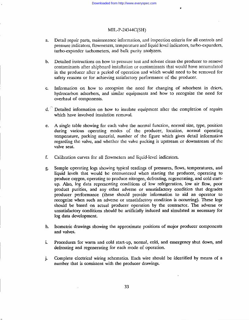
a. Detail repair parts, maintenance information, and inspection criteria for all controls andpressure indicators, flowmeters, temperature and liquid level indicators, turbo-expanders,turbo-expander tachometers, and bulk purity analyzers.
b. Detailed instructions on how to pressure test and solvent clean the producer to removecontaminants after shipboard installation or contaminants that would have accumulatedin the producer after a period of operation and which would need to be removed forsafety reasons or for achieving satisfactory performance of the producer.
c. Information on how to recognize the need for changing of adsorbent in driers,hydrocarbon adsorbers, and similar equipments and how to recognize the need foroverhard of components.
d. ““’Detailed information on how to insulate equipment after the completion of repairswhich have involved insulation removal.
e. A single table showing for each valve the normal function, normal size, type, positionduring various operating modes of the producer, location, normal operatingtemperature, packing material, number of the figure which gives detail informationregarding the valve, and whether the valve packing is upstream or downstream of thevalve seat.
f. Calibration curves for all flowrrreters and liquid-level indicators.
& Sample operating logs showing typical readings of pressures, flows, temperatures, andliquid levels that would be encountered when starting the producer, operating toproduce oxygen, operating to produce nitrogen, defrosting, regenerating, and cold start-UP. Afso, log data representing conditions of low refrigeration, low air flow, poorproduct purities, and any other adverse or unsatisfactory condition that degradesproducer performance (these should provide information to aid an operator torecognize when such an adverse or unsatisfactory condition is occurring). These logsshould be based on actual producer operation by the contractor. The adverse orunsatisfactory conditions should be artificially induced and simulated as necessary forlog data development.
h. Isometric drawings showing the approximate positions of major producer componentsand valves.
i. Procedures for warm and cold start-up, normal, cold, and emergency shut down, anddefrosting and regenerating for each mode of operation.
j. Complete electrical wiring schematics. Each wire should be identified by means of anumber that is consistent with the producer drawings.
33
Downloaded from http://www.everyspec.com

MIL-P-24344C(SH)
k. Complete piping schematics. Each piping run should be identified by means of anumber thaL is consistent with the producer drawings.
1. Complete process flow diagrams.
m. Complete identification (including original vendor’s name,: part number, and CAGE)of consumables such as fuses, absorbents, insulation, lubricants, chemicals, and so forth.
n. Complete exploded view drawings of repairable components,
o. Dimensions on repairable components with appropriate wear and replacement criteria.
p...: SPecial tOols or test equipment for disassembly, assembly, and testing of producercomponents.
q. A table showing when maintenance is required (action and frequency) along withdetailed procedures for maintenance accomplishment.
34
Downloaded from http://www.everyspec.com

MIL-P-24344C(SH)
APPENDIX F
MILESTONE REPORT TECHNICAL CONTENT REQUIREMENTS
10. SCOPE
10.1 Scope. ~isappendti covers thelechnical requirements formilatone re~r@ covered bythis specification. This appendix is not a mandatory part of this specification. The informationcontained,herein is intended for guidance only.
20. APPLICABLEDOCUMENTS
This section is not applicable to this appendix.
30. REPORT CONTENTS
30.1 Milestone reports. Bi-monthly progress repnrts should be prepared which state thedegree of completion, work planned to achieve completion, and probIems that could delaycompletion of the producer. Reports should include all items in the contract.
35
Downloaded from http://www.everyspec.com

MIL-P-24344C(SH)
APPENDIX G
FAfLURE/MALFUNCTION REPORT TECHNICAL CONTENT REQUIREMENTS
10. SCOPE
10.1 Scope. This appendix covers the technical requirements for failure/malfunction reportscovered by this specification. This appendix is not a mandatory part of this specification. Theinformation contained herein is intended for guidance orrIy.
20. APPLICABLE DOCUMENTS
This section is not applicable to this appendix.
30. REPORT CONTENT
30.1 Faihrre/malfunction data. A report should be prepared to document each and everyincident of failure/malfrmction that occurs during component tests, subassembly tests, factorycheckout tests (that is, contractor’s tests accomplished prior to the quality assurance tests specifiedherein) of each producer, and the quality assurance tests specified herein.
36
Downloaded from http://www.everyspec.com

MIL-P-24344C(SH)
APPENDIX H
CHEMICAL REQUIREMENTS FOR INSULATION MATERIAL
10. SCOPE
10.1 Scope. This appendix covers chemical requirements for mineral-based thermal insulation.This appendix is a mandatory pmt of tbe specification. The information contained herein isintended ~ compliance.
20. APPLICABLE DOCUMENM
20.1 Non-Goverrsmerrt publications. The following document(s) form h part of this documentto the extend specified herein. Unless otherwise specified, the issues of the documents which areDOD adopted are those listed in the issue of the DODISS cited in the solicitation. Unlessotherwise specified, the issues of documents not listed in the DODLSS are the issues of thedocuments cited in the solicitation (see 6.2).
AMERICAN SOCIETY FOR TESTING AND MATERIALS (ASTM)
D 512 Standard Test Methods for Chloride Ion In WateL (DOD adopted)
E60 Standard Practice for Photometric and Spectrophotometric Methods for ChemicalAnalysis of Metals; (DOD adopted)
E 62 Standard Methods for Chemical Analysis of Copper and Copper ABoys(Photometric Methods)
E 120 Standard Methods for Chemical Analysis of Titanium and Titanium Afloys; (DODadopted)
E 146 Standard Methods for Chemical Analysis of Zkconium and Zbconium Afloys;(DOD adopted)
(Application for copies should be addressed to the American Society for Testing and Materiafs,1916 Race Street, Philadelphia, PA 19103.)
(Non-Government standards and other publications are normally available from the organizationsthat prepare or distribute the documents. These documents also may be available in or throughlibraries or other informational services.)
37
Downloaded from http://www.everyspec.com

MIL-P-24344C(SH)
30. CHEMICAL REQUIIWMENIS
30.1 Analysis. The specific material supplied shall be analyzed for the following leachableions: (1) Chloride, (2)sodium orsilica!c (if necessary to meet tbe acceptance requirement of figurel, both sodium and silicate should be analyzed). The plot point of these analyses shall fall in theacceptable area of figure 1. The acccpkmce - rejection curve may be extrapolated, as necessary,to determine the acceptability of plot points which fall outside the area actually bounded by figurel. However, the minimum allowable value ofsodium plus silicate shall be 50p/m.
30.2 Hydrogen-ion concentration. Leach water from the material shail have a hydrogen-ionconcentration negative exponent (pH) not greater than 11.2.
40. QUALITY CONFORMANCE’IESTS
40.1 I-atsize and sampling. For the purpose of this specification a lot shall consist of oneproduction batch produced at one time under the same conditions and from ingredients of thesame kind, nature, and quality. A minimum of three samples shall be taken from each lot for thequality conformance test. The sample shall be fully representative of the cross section of thematerial. Samples shall rewrapped inclear polyethylene sheets orplaced in polyethylene envelopesas is suitable to protect the sample from contamination. Cleaned rubber or plastic gloves shall beworn while taking and handling the sample to avoid chlnride contamination from perspiration orother contamination. The gloves shall be of material which does not have chloride containingcompounds such as neoprene, saran, or metallic chlorides in its formulation. Prior to use, thegloves shall be rinsed twice in separate lots of boiling wate~ each rinsing shall be followed bythorough draining. The gloves shall then be air dried and stored in a closed container.
40.2 Leaching procedure prior tochemicaltests.Equipment, took., and reagents used forspecimen preparation andleaching shall beclean andsufficiently free ofchlorides, silicates, sodium,or acidic or alkaline materials which might otherwise affect the chemical tests. Water used inleaching shall be demineralized water meeting tbe following specifications 0.1 p/m maximumchlorides, 2.5microsiemens percubic centimeter @cm3) maximum conductivity, 6.Ominimum and8.0 maximum pH (water shall not be stored inglass, ceramic, oranyother container in which itcould pick up chloride, silicate, or sodium ions).
40.2.1 Specimen preparation. Tw020 gram specimens shall be taken from each sample. Thespecimen shall be proportionally representative of the entire composition. The specimen shall beprepared as follow ~especimen shall bepulverized inablender operated athighspeedfor3Oto 60 seconds. The sample shall contain no large lumps. Sample portions may be cut or brokeninto smaller pieces prior to pulverizing.
40.2.2 Water leaching. Place each specimen in an individual 8tKl milliliter pyrex beaker (orequal) and cover the specimen with 400 milliliters of water. Cover the beaker with a watch glassand heat for one-half hour at 95 to 100 “C, then remove heat. Aflow the beaker and its contentsto cool to a room temperature of 20 to 30 “C, Filter the leach solution through a prewashednumber 41 Whatman, or equal, filter paper in a Buchners type funnel, transferring the speeimen
38
Downloaded from http://www.everyspec.com

MIL-P-24344C(SH)
to the funnel and using light suction as necessary. The beaker and the specimen shall be washedthoroughly using a minimum of 10 small washes to make up the filtrate to 500 milliliters. Thefiltrate shall retransferred toapolyethylene container and marked absolution A- This solution Ashall be the source of aliquots for the chemical tests. Approximately 150 milliliters of solution A,from which afiquots for the sodium andsilicate tests are to be taken, shall be refiltered througha 0.45 millipore filter.
40.3 Chemicaltests.The chemical tests shall be performed on the duplicate leach solutionsAobtained from tbeduplicate specimens. The chemical analyses forchlorine, sodkrm, and silicateions shall be calculated on the basis of the weight of the specimen. The pH shall be reported astbe pH of solution A.
40.3.1,PH. The pH shall be determined on the aliquot from solution A using a BeckmanZeromatic (or equal) pHmeter. Aiquots shall bediscarded after thedetermination. ~epH shallbe corrected to25”C.
40.3.2 Chemical mmlyses. The chemical analyses for the chloride, silicate and sodium ionssballbemade by the method contairrcd in this specification, or equal as approved in writing by thecommand or agency concerned. Request for approval of alternate chemistry procedures shall beaccompanied by justification evidence of their accuracy, such as by measuring differences in testresults when known amounts of chlorides, silicates, or sodium are added and comparing thesedifferences with comparable results obtained when using tbe procedures contained in thisspecification on the same samples of insulation. The analyses shall be made on suitable aliquotsfrom solution A.
40.3.2.1Analysis for chloride. An aliquot of solution A shall be analyzed by either of thefollowing methods
a. Amperometric-coulomefric tifrutor method. An amperometric-corrlometric titrator methodsuch as the Aminco-Cotlove Automatic Chloride Titrator method, or equal.
h. Calorimetric melliod:
(1) An optical density shall be measured on a prepared solution against a waterreference solution in five centimeter cells by a Beckman model Bspectrophotometer or equal at 470miOimicron and thechloride eontent read fromacalibration crrrve made from aliquots ofastandard chloride solution representing20, 40, 60, 80, and 100 micrograms of chloride ion. Both a sample blank and areagent bkmk shall be used and the reading obtained on solution A shall becorrected by subtracting the sum of the blank readings. Notex Sulphate andphosphate cause positive interference at concentrations exceeding 0.2 weightpercent.
(2) Addintrrrn toa50milliliter volumetric flask Analiquot ofsolution A whichcontains 20t060micrograms ofchloride ion (adjusted topH6t08with 6 Normal
39
Downloaded from http://www.everyspec.com

MIL-P-24344C(SH)
HN03 using indicating paper), 2 milliliters each o[ reagents a. and b., and waterto 50 milliliters, mixing thoroughly at each addition. Read 15 minutes afterpreparation, mixing the solutions thoroughly just prior threading.
‘(3)Reagents shall be of suitabie analytical grade. Reagent solutions shall have thefollowing composition:
(a) 99.7grams of Fe2(S04)3(NH4)2S0424H20 perliter disso1vedin6 Normalnitric acid. Store in a brown bottle for at least 24 hours before use.
(b) 7.5grams of Hg(SCN)2dissolved inmethyl alcohol to. final volume of5Wmilliliters after rnixhrg at least one borsr with a stirrer and filtering throughWhatmannumber41 paper (or equal).
(c) Water shall be dis[illed water containing less than 0.1 parts per million ofchloride ior’r.Note: Forreference, seerirethod Cof ASTM D512.
40.3.2.2 Calorimetric method for silicate. Analiquot ofmillipore filtered solution Ashallbeanalyzed photometrically (see ASTM E (KI) for silicates by either of the following methods,modified as required to suit the leach water
a. Tbemolybdisilicic acid method inaccordance with ASTME62b. The molybdenum blue method in accordance with ASTM E 1200r ASTM E 146.
40.3.2.3 Analysisforsodium.A 100 milliliter aliquot of millipore filtered solution Ashallbeanalyzed by either of the following methods
a. Spectrognrphic method. The solution is reduced to dryness under infrared lamps in atared platinum dish. The residue is then analyzed spectrograpbieally for sodium.
b. l%rmephotome~ric method. The millipore filtered solution shall be used for the flamephotometric analysis. Note: Corrections must be made if high concentrations ofalkaline oralkalirre earth metals such as calcium, potassium or magnesium are present.
40.3.3 Acceptance.If the average analysis of the two specimens taken from any sample failstoconform totherequirements of3.1 and3.2tbe lot represented by that sample shallberejected.
40
Downloaded from http://www.everyspec.com

MIL-P-24344C(SH)
10,000
I,000
‘%v<0.
100
.//“
10too 1,000 10,000 100,000
p/m(Na + Si03)
FIGURE 1. Acceptability of insulation on the basis of the p[ot points of thech!on”de,sodium, and silicate ions.
41
Downloaded from http://www.everyspec.com
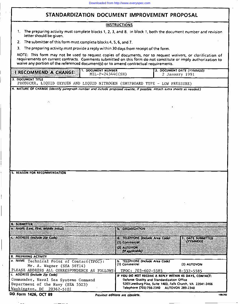
.-. . --- -- , ,. .,”.. .-. .,”.” .,. “-.. . . .
..— .—..
Downloaded from http://www.everyspec.com


![IINCH-POUND ] MIL-S-24235/16B (SH) 28 December 1992 …everyspec.com/MIL-SPECS/MIL-SPECS-MIL-S/download.php?... · iinch-pound ] mil-s-24235/16b (sh) 28 december 1992 superseding](https://img.dokumen.tips/doc/110x75/614879662918e2056c22b67c/iinch-pound-mil-s-2423516b-sh-28-december-1992-iinch-pound-mil-s-2423516b.jpg)