Embed Size (px)
Citation preview

T-SB-0012-11 Rev1 February 14, 2011
MIL "ON" and/or Rattle Noise from Engine (2AR)
ServiceCategory Engine/Hybrid System
Section Engine Mechanical Market USA
Applicability
YEAR(S) MODEL(S) ADDITIONAL INFORMATION
2010 – 2011 Camry Drive Type(s): 2WDEngine(s): 2ARTransmission(s): 6MT, 6ATVDS(s): BF3EKWMI(s): 4T1, 4T4, JTN
2009 – 2010 RAV4 Drive Type(s): 4WD, 2WDEngine(s): 2ARTransmission(s): 4ATVDS(s): BF31V, BF32V, BF33V, BF34V, BF35V,BF4DV, DF4DV, EF4DV, JF4DV, KF4DV, RF4DV,WF4DV, XF4DV, YF4DV, ZF31V, ZF32V, ZF33V,ZF34V, ZF35V, ZF4DVWMI(s): 2T3, JTM
TSB REVISION NOTICE
July 28, 2011 Rev1:
• Introduction, Production Change Information, Warranty, and Parts Information hasbeen updated.
Any previous printed versions of this service bulletin should be discarded.
© 2011 Toyota Motor Sales, USA Page 1 of 25

T-SB-0012-11 Rev1 February 14, 2011 Page 2 of 25
MIL "ON" and/or Rattle Noise from Engine (2AR)
Introduction
Some 2010 – 2011 model year Federal Emissions Specification Camry vehicles and 2009 – 2011model year RAV4 vehicles equipped with the 2AR-FE engine may exhibit one or more of thefollowing conditions:
• MIL “ON” with DTC P0015 and/or P0017 setting
• P0015 — Camshaft position “B” – Timing over-retarded (Bank 1)
• P0017 — Crankshaft position – Camshaft position correlation (Bank 1 Sensor B)
• Rattle noise from the engine
Follow the repair procedure in this bulletin to address this condition.
NOTEThis TSB does NOT apply to 2010–2011 model year California Emissions Specification Camryvehicles.
Production Change Information
This TSB applies to the following vehicles:
• All 2010 Federal Emissions Specification Camry vehicles.
• 2011 Federal Emissions Specification Camry vehicles produced BEFORE the ProductionChange Effective VINs shown below.
MODEL PLANT DRIVETRAIN PRODUCTION CHANGE EFFECTIVE VIN
TMMK Line 1 4T1BF3EK#BU182097
TMMK Line 2 4T1BF3EK#BU646187
SIA 4T4BF3EK#BR137403Camry
Tsutsumi
FWD
JTNBF3EK#B3009591
• All 2009 RAV4 vehicles.
• 2010 RAV4 vehicles produced BEFORE the Production Change Effective VINs shown below.
MODEL PLANT DRIVETRAIN PRODUCTION CHANGE EFFECTIVE VIN
2WD 2T3#F##V#AW051643TMMC
4WD 2T3#F##V#AW080481
2WD JTM#F##V#A5031691Tahara
4WD JTM#F##V#A5036832
2WD JTM#F##V#AD029196
RAV4
Shokki4WD JTM#F##V#AD039824
© 2011 Toyota Motor Sales, USA

T-SB-0012-11 Rev1 February 14, 2011 Page 3 of 25
MIL "ON" and/or Rattle Noise from Engine (2AR)
Warranty Information
OP CODE DESCRIPTION MODEL TIME OFP T1 T2
Camry 2.6EG1015 R & R Camshaft Timing Exhaust
Gear Assembly RAV4 2.4
Camry 1.8
Combo ARemove Oil Pan to Replace Additional
Components as Needed & RemoveSeparated Camshaft Timing Exhaust
Gear Pieces
RAV4(2WD,4WD)
1.9
Camry 8.5
RAV4(2WD) 8.4Combo B
Remove Timing Cover to ReplaceAdditional Components as Needed &Remove Separated Camshaft Timing
Exhaust Gear Pieces RAV4(4WD) 9.2
13070-##### 06 16
APPLICABLE WARRANTY• This repair is covered under the Toyota Powertrain Warranty. This warranty is in effect for 60
months or 60,000 miles, whichever occurs first, from the vehicle’s in-service date.
• Warranty application is limited to occurrence of the specified condition described in thisbulletin.
© 2011 Toyota Motor Sales, USA

T-SB-0012-11 Rev1 February 14, 2011 Page 4 of 25
MIL "ON" and/or Rattle Noise from Engine (2AR)
Parts Information
PREVIOUS PART NUMBER CURRENT PART NUMBER PART NAME QTY
13070-0V01013070-0V01113070-0V01213070-3601013070-36011
13070-0V013 Gear Assy, Camshaft Timing Exhaust(Federal Emissions Specification ONLY) 1
11213-36020 Same Gasket, Cylinder Head Cover 1
11159-0V010 Same Gasket, Camshaft Bearing Cap OilHole No. 1 2
90430-A0001 Same Gasket, Camshaft Bearing Cap OilHole No. 2 1
11328-0V010 Same Gasket, Timing Chain Tensioner 1
11329-36010 Same Gasket, Timing Chain Cover, No. 2 1
The Following Part Is Only Necessary in the Case of Oil Pan Sub-assembly Removal:15147-36010 Same Gasket, Oil Strainer 1
The Following Parts Are Only Necessary in the Case of Timing Cover Removal:15193-36010 Same Gasket, Oil Pump No. 1 1
15197-36010 Same Gasket, Oil Pump No. 2 1
11496-36010 Same Gasket, Oil Hole Cover 1
Required Tools & Equipment
REQUIRED EQUIPMENT SUPPLIER PART NUMBER QTY
TIS Techstream*orTechstream Lite
NOTE: Software version 5.10.029 or later is required.
ADETSPKG1
orTSLITEDLR01
1
SPECIAL SERVICE TOOLS (SST) PART NUMBER QTY
Torque Wrench Adapter* 09249-63010-01 1
© 2011 Toyota Motor Sales, USA

T-SB-0012-11 Rev1 February 14, 2011 Page 5 of 25
MIL "ON" and/or Rattle Noise from Engine (2AR)
Required Tools & Equipment (Continued)
REQUIRED MATERIAL QUANTITY
Toyota Genuine Seal Packing Black, Three Bond 1207B, or equivalent As Needed
Engine Oil As Needed
Coolant As Needed
NOTE• Additional Techstream units may be ordered by calling Approved Dealer Equipment (ADE) at
1-800-368-6787.
• Additional SSTs may be ordered by calling 1-800-933-8335.
* Essential SST.
Repair Procedure Overview
1. Remove the camshaft timing exhaust gear assembly.
2. Inspect the gear for separated pieces.
3. Remove the oil pan sub-assembly and timing cover as needed to remove the separated piece(s)and repair/replace additional components as needed.
4. Complete the repair.
Repair Procedure
1. Confirm the customer complaint.
2. Remove the cylinder head cover.
A. Relocate the engine harness that lies acrossthe top of the cylinder head cover.
B. Remove the ignition coils.
C. Remove the 16 bolts and cylinder head cover.
Figure 1. .
3. Remove the chain tensioner.
A. Remove the right front wheel.
B. Remove the front fender apron seal RH.
© 2011 Toyota Motor Sales, USA

T-SB-0012-11 Rev1 February 14, 2011 Page 6 of 25
MIL "ON" and/or Rattle Noise from Engine (2AR)
Repair Procedure (Continued)
C. Remove the V-ribbed belt for the vane pump.
D. Rotate the crankshaft clockwise and set the No. 1 cylinder at +10◦ from the TDC/compression.
E. After the timing marks are aligned on the VVTgear, place paint marks on the chain and bothgears.
Figure 2.
1
1 Timing Marks
F. Rotate the crankshaft counterclockwise by 10◦ and loosen the tension of the chain.
G. Remove the timing chain cover plate.
H. Align the holes of the stopper plate andtensioner, and insert a pin into the stopperplate hole to lock the tensioner.
Figure 3.
1
2
1 Stopper Plate
2 Timing Tensioner
I. Remove the 2 bolts and chain tensioner.
© 2011 Toyota Motor Sales, USA

T-SB-0012-11 Rev1 February 14, 2011 Page 7 of 25
MIL "ON" and/or Rattle Noise from Engine (2AR)
Repair Procedure (Continued)
4. Remove the timing chain guide by removing thebolt.
Figure 4. .
5. Remove the intake side VVT gear.
A. For Camry ONLY:Remove the 2 bolts and the No. 2 timingchain cover (Figure 5).
Figure 5.
B. Remove the service hole plug. Figure 6.
1
1 Service Hole Plug
© 2011 Toyota Motor Sales, USA

T-SB-0012-11 Rev1 February 14, 2011 Page 8 of 25
MIL "ON" and/or Rattle Noise from Engine (2AR)
Repair Procedure (Continued)
C. Insert the tool through the service hole andremove the bolt of the intake VVT gear whileholding the camshaft stationary with a wrench.
NOTICE
• Be careful NOT to damage the cylinderhead or spark plug tube with thewrench.
• Do NOT disassemble the camshafttiming gear.
Figure 7.
D. After the VVT gear is slid in the arrow directionas shown in Figure 8, lower the VVT gear andremove the chain from the VVT gear.
Figure 8.
E. Remove the VVT gear from the cam housing.
© 2011 Toyota Motor Sales, USA
T-SB-0012-11 Rev1 February 14, 2011 Page 9 of 25
MIL "ON" and/or Rattle Noise from Engine (2AR)
Repair Procedure (Continued)
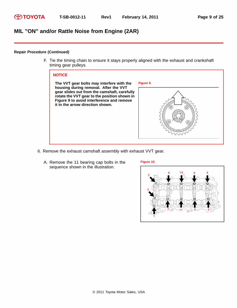
F. Tie the timing chain to ensure it stays properly aligned with the exhaust and crankshafttiming gear pulleys.
NOTICE
The VVT gear bolts may interfere with thehousing during removal. After the VVTgear slides out from the camshaft, carefullyrotate the VVT gear to the position shown inFigure 9 to avoid interference and removeit in the arrow direction shown.
Figure 9.
6. Remove the exhaust camshaft assembly with exhaust VVT gear.
A. Remove the 11 bearing cap bolts in thesequence shown in the illustration.
Figure 10.
9
1
2
3
4
5
6
7
810
11
© 2011 Toyota Motor Sales, USA

T-SB-0012-11 Rev1 February 14, 2011 Page 10 of 25
MIL "ON" and/or Rattle Noise from Engine (2AR)
Repair Procedure (Continued)
B. Using several steps, remove the 10 bearingcap bolts in the sequence shown in theillustration.
Figure 11.
2
3
4
5
6
7
8
9
10
1
C. Remove the 5 bearing caps.
HINTArrange the removed bearing caps in order to ensure they are installed in their originallocations during reassembly.
D. Remove the exhaust camshaft assembly with camshaft timing exhaust gear.
E. Place additional ties on the timing chain to ensure it stays properly aligned with the crankshafttiming gear pulley.
F. Place the exhaust camshaft with camshaft timing exhaust gear in a vise.
HINTCover the vise with tape and only apply pressure to one of the hexagonal portions ofthe camshaft.
G. Remove the bolt and camshaft timing exhaust gear assembly.
© 2011 Toyota Motor Sales, USA

T-SB-0012-11 Rev1 February 14, 2011 Page 11 of 25
MIL "ON" and/or Rattle Noise from Engine (2AR)
Repair Procedure (Continued)
H. Inspect the camshaft timing exhaust gearassembly.
Is there a section separated from the gear asshown in Figure 12?
• YES — Go to “Additional RepairProcedure: Part A” in this TSB for removalof the oil pan and, if necessary, the timingcover assembly, to remove the separatedpiece(s) and perform additional repairs.
• NO — Go to step 7.
Figure 12.
7. Install the new camshaft timing exhaust gear assembly.
A. Align and attach the knock pin of the No. 2camshaft with the pin hole of the camshafttiming exhaust gear.
Figure 13.
1
2
1 Pin Hole
2 Knock Pin
© 2011 Toyota Motor Sales, USA

T-SB-0012-11 Rev1 February 14, 2011 Page 12 of 25
MIL "ON" and/or Rattle Noise from Engine (2AR)
Repair Procedure (Continued)
B. Check that there is no clearance between thecamshaft timing exhaust gear and camshaftflange.
Figure 14.
1
2
34
6
5
1 Incorrect
2 Correct
3 Camshaft Timing Exhaust Gear
4 Clearance
5 Flange
6 No Clearance
C. With the exhaust camshaft still secured in the vise, install the bolt.Torque: 85 N*m (867 kgf*cm, 63 ft*lbf)
D. Clean the camshaft journals, camshaft housing, and bearing caps.
E. Apply a light coat of engine oil to the camshaft journal, camshaft housing, and bearing caps.
F. Install the exhaust camshaft with new camshaft timing exhaust gear assembly installed.
© 2011 Toyota Motor Sales, USA

T-SB-0012-11 Rev1 February 14, 2011 Page 13 of 25
MIL "ON" and/or Rattle Noise from Engine (2AR)
Repair Procedure (Continued)
8. Install the camshaft bearing cap.
A. Confirm the marks and numbers on thecamshaft bearing caps and place them in theirproper positions and directions.
Figure 15.
1
2 3 4 5
B. Using several steps, uniformly tighten the10 bolts in the sequence shown in theillustration.Torque: 27 N*m (275 kgf*cm, 20 ft*lbf)
Figure 16.
2
3
4
5
6
7
8
9
10
1
C. Install the 11 bolts in the order shown in theillustration.Torque: 16 N*m (163 kgf*cm, 12 ft*lbf)
NOTICEMake sure that the camshaft rotatessmoothly after installing the bearing caps.
Figure 17.
9
1
2
3
4
5
6
7
810
11
© 2011 Toyota Motor Sales, USA

T-SB-0012-11 Rev1 February 14, 2011 Page 14 of 25
MIL "ON" and/or Rattle Noise from Engine (2AR)
Repair Procedure (Continued)
9. Install the intake side VVT gear.
A. Confirm the gear is in the unlocked positionprior to installation.
NOTICEThe camshaft timing gear MUST be in theunlocked position when installing on thecamshaft to prevent damage to the lock pinduring tightening. Please see step 9D forinstructions to unlock the camshaft timinggear.
Figure 18.
1
2
3
4
3
4
1 Advanced (Unlocked) Position
2 Retarded (Locked) Position
3 Knock Pin Hole
4 Alignment Mark
B. Remove any remaining ties from the timing chain.
© 2011 Toyota Motor Sales, USA

T-SB-0012-11 Rev1 February 14, 2011 Page 15 of 25
MIL "ON" and/or Rattle Noise from Engine (2AR)
Repair Procedure (Continued)
C. Insert the tool from the service hole and installthe bolt of the intake VVT gear.
NOTICEMake sure NOT to lock the camshaft timinggear. If the camshaft timing gear is locked,release the lock according to the followingprocedure (step 9D).
Figure 19.
D. Inspect the camshaft timing gear lock.
If the camshaft timing gear is locked, release the lock according to the following procedure.
(1) After cleaning and degreasing the intakeside VVT oil hole on the No. 1 camshaftbearing cap, completely seal the oil holewith adhesive tape or equivalent asshown to prevent air from leaking.
NOTICEBe sure to seal the oil hole completelybecause air leaks due to insufficientsealing will prevent the lock pin frombeing released.
Figure 20.
1
2
3
1 Adhesive Tape
2 Adhesive Tape Sealing Area
3 Small Hole Here
(2) Make a hole in the adhesive tape covering the oil hole as shown in Figure 20.
© 2011 Toyota Motor Sales, USA

T-SB-0012-11 Rev1 February 14, 2011 Page 16 of 25
MIL "ON" and/or Rattle Noise from Engine (2AR)
Repair Procedure (Continued)
(3) Apply approximately 200 kPa(2.0 kgf/cm2, 29 psi) of air pressure tothe hole made in the preceding step,then forcibly turn the camshaft timinggear assembly in the advance direction(counterclockwise).
CAUTIONCover the oil passages with a piece ofcloth when applying pressure to keepoil from splashing.
NOTICE
• If air leaks out, reattach theadhesive tape.
• Do NOT allow the camshaft timinggear assembly to lock. If it locks,release the lock pin again.
HINT
• The camshaft timing gearassembly may be turned inthe advance direction withoutapplying any force.
• If enough air pressure cannot beapplied because of air leakagefrom the port, releasing the lockpin may be difficult.
Figure 21.
1
1 Compressed Air
(4) Remove the adhesive tape on the VVT hole.
E. Tighten the bolt of the intake VVT gear.Torque: 85 N*m (867 kgf*cm, 63 ft*lbf)
F. Lock the gear by rotating the camshaft timing gear assembly clockwise.
© 2011 Toyota Motor Sales, USA

T-SB-0012-11 Rev1 February 14, 2011 Page 17 of 25
MIL "ON" and/or Rattle Noise from Engine (2AR)
Repair Procedure (Continued)
10. Install the service hole plug with a new gasket.Torque: 30 N*m (306 kgf*cm, 22 ft*lbf)
Figure 22..
1
1 Service Hole Plug
11. For Camry ONLY:Install the No. 2 timing chain cover with the2 bolts.Torque: 10 N*m (102 kgf*cm, 7 ft*lbf)
Figure 23. .
12. Install the timing chain guide with the bolt.Torque: 21 N*m (214 kgf*cm, 15 ft*lbf)
Figure 24. .
© 2011 Toyota Motor Sales, USA

T-SB-0012-11 Rev1 February 14, 2011 Page 18 of 25
MIL "ON" and/or Rattle Noise from Engine (2AR)
Repair Procedure (Continued)
13. Install the chain to the VVT gear.
NOTICEAlign the marks that were placed on the gearsand chain.
Figure 25. .
1
1 Timing Marks
14. Install the chain tensioner.
A. Install the chain tensioner to the service hole.Torque: 10 N*m (102 kgf*cm, 7 ft*lbf)
B. When installing the tensioner, pull out the pinand release the tensioner.
C. Install the timing chain cover plate.
Install a new gasket and the timing chain coverplate with the 4 bolts.Torque: 10 N*m (102 kgf*cm, 7 ft*lbf)
Figure 26. .
1
2
1 Stopper Plate
2 Timing Tensioner
15. Install the cylinder head cover sub-assembly.
A. Apply a light coat of engine oil to 3 new gaskets.
© 2011 Toyota Motor Sales, USA

T-SB-0012-11 Rev1 February 14, 2011 Page 19 of 25
MIL "ON" and/or Rattle Noise from Engine (2AR)
Repair Procedure (Continued)
B. Install the 3 gaskets to the camshaft bearingcaps.
Figure 27.
C. Install a new gasket to the cylinder head cover.
NOTICERemove any oil from the contact surface.
D. Apply seal packing as shown.Seal Packing: Toyota Genuine Seal PackingBlack, Three Bond 1207B, or equivalentStandard Seal Diameter: 3.0 to 6.0 mm(0.118 to 0.236 in.)Application Width A: 5.0 mm (0.197 in.)
NOTICE
• Remove any oil from the contactsurface.
• Install the cylinder head cover within3 minutes and tighten the bolts within15 minutes after applying seal packing.
Figure 28.
1
1
A A
2 3
4
1 Seal Packing
2 Timing Chain Cover
3 Camshaft Housing
4 3.0 to 6.0 mm
A Application Width “A”
© 2011 Toyota Motor Sales, USA

T-SB-0012-11 Rev1 February 14, 2011 Page 20 of 25
MIL "ON" and/or Rattle Noise from Engine (2AR)
Repair Procedure (Continued)
E. Align the cylinder head cover with pin A.Then align the cylinder head cover with pin Band install the cylinder head cover.
Figure 29.
A
B
9
1, 192, 20 3, 21
4, 12
5, 1867
8
10
17
16
15
141311
A Pin A
B Pin B
F. Install the 16 bolts and then tighten the bolts in the order shown in Figure 29.Torque: 12 N*m (122 kgf*cm, 9 ft*lbf)
NOTICEDo NOT fill the engine with oil or start and run the vehicle for at LEAST 4 hours after theinstallation.
G. Confirm proper engine and coolant levels prior to starting the engine and test driving thevehicle.
H. Clear DTCs with Techstream.
16. Confirm the repair.
© 2011 Toyota Motor Sales, USA

T-SB-0012-11 Rev1 February 14, 2011 Page 21 of 25
MIL "ON" and/or Rattle Noise from Engine (2AR)
Additional Repair Procedure: Part A
Remove the oil pan sub-assembly to remove the separated piece(s) of the camshaft timing exhaustgear and repair/replace additional components as needed.
Removal
1. Remove the oil pan sub-assembly.
A. Remove the 11 bolts and 2 nuts. Figure 30.
1
1 Nuts
B. Insert the blade of an oil pan seal cutterbetween the oil pan and stiffening crankcase,cut off the applied sealer, and remove the oilpan.
NOTICE
• Be careful NOT to damage the stiffeningcrankcase contact surface of the oilpan.
• Be careful NOT to damage the stiffeningcrankcase flange.
Figure 31.
© 2011 Toyota Motor Sales, USA

T-SB-0012-11 Rev1 February 14, 2011 Page 22 of 25
MIL "ON" and/or Rattle Noise from Engine (2AR)
Additional Repair Procedure: Part A (Continued)Additional Repair Procedure: Part A
Removal (Continued)
2. Remove the oil strainer sub-assembly byremoving the 3 bolts, oil strainer, and gasket.
Figure 32. .
3. Remove the No. 1 oil pan baffle plate by removingthe 5 bolts.
Figure 33. .
4. Remove the separated piece(s) of the camshaft timing exhaust gear assembly.
5. Clean the oil pan sub-assembly and related components prior to reassembly.
© 2011 Toyota Motor Sales, USA

T-SB-0012-11 Rev1 February 14, 2011 Page 23 of 25
MIL "ON" and/or Rattle Noise from Engine (2AR)
Additional Repair Procedure: Part A (Continued)
Installation
1. Install the No. 1 oil pan baffle plate.
Install the oil pan baffle plate and uniformly tightenthe 5 bolts in several steps, in the sequenceshown in the illustration.Torque: 10 N*m (102 kgf*cm, 7 ft*lbf)
Figure 34. .
1
2
3
4
5
2. Install the oil strainer sub-assembly.
A. Apply a light coat of engine oil to a new gasket.
B. Align the protrusion of the gasket with thecutout of the oil strainer, and install the gasketto the oil strainer.
C. Install the oil strainer with the 3 bolts inseveral steps, in the sequence shown in theillustration.Torque: 10 N*m (102 kgf*cm, 7 ft*lbf)
Figure 35. .
1
2 3
1
1 Protrusion
© 2011 Toyota Motor Sales, USA

T-SB-0012-11 Rev1 February 14, 2011 Page 24 of 25
MIL "ON" and/or Rattle Noise from Engine (2AR)
Additional Repair Procedure: Part A (Continued)Additional Repair Procedure: Part A
Installation (Continued)
3. Install the oil pan sub-assembly.
A. Apply seal packing in a continuous line asshown in the illustration.Seal Packing: Toyota Genuine Seal PackingBlack, Three Bond 1207B, or equivalentStandard Seal Diameter: 2.5 to 3.5 mm (0.0984to 0.138 in.)
NOTICE
• Remove any oil from the contactsurface.
• Install the oil pan within 3 minutes andtighten the bolts and nuts within 10minutes after applying seal packing.
• Do NOT apply oil for at least 4 hoursafter the installation.
Figure 36.
1
1 Seal Packing: 2.5 to 3.5 mm
4. Install the oil pan with the 11 bolts and 2 nutsin several steps, in the sequence shown in theillustration.Torque: 10 N*m (102 kgf*cm, 7 ft*lbf)
HINTBolt A and nut B are tightened twice.
Figure 37. .
1, 9
2, 153
4
5
67
810
14
13
12
11
A
B
C
A Bolt A
B Nut B
C Nuts
5. Were all the separated pieces of the camshaft timing exhaust gear found?
• YES — Go to “Repair Procedure”, step 7.
• NO — Go to “Additional Repair Procedure: Part B”.
© 2011 Toyota Motor Sales, USA

T-SB-0012-11 Rev1 February 14, 2011 Page 25 of 25
MIL "ON" and/or Rattle Noise from Engine (2AR)
Additional Repair Procedure: Part B
1. Remove the timing chain cover to remove the separated piece(s) of the camshaft timing exhaustgear and repair/replace additional components as needed.
Refer to the Technical Information System (TIS), applicable model and model year RepairManual:
• 2009 RAV4:Engine/Hybrid System – Lubrication – “2AR-FE Lubrication: Oil Pump:Removal / Installation”
• 2010 RAV4:Engine/Hybrid System – Lubrication – “2AR-FE Lubrication: Oil Pump:Removal / Installation”
• 2010 Camry:Engine/Hybrid System – Lubrication – “2AR-FE Lubrication: Oil Pump:Removal / Installation”
• 2011 Camry:Engine/Hybrid System – Lubrication – “2AR-FE Lubrication: Oil Pump:Removal / Installation”
2. Go to “Repair Procedure”, step 7, to complete the repair.
© 2011 Toyota Motor Sales, USA