Embed Size (px)
Citation preview
8/28/2014
Internetworking 1
MikroTik RouterOS
Training
Inter-Networking
©Mikrotik 2012 2
Overview
● BGP
● BGP Basics (iBGP, eBGP)
● Distribution, filtering and BGP attributes
● MPLS
● Introduction to MPLS
● LDP
● L2 and L3 VPN's
● Traffic Engineering
©Mikrotik 2012 3
Lab Setup
● Divide in groups by four
● Make network setup as illustrated in next slide
● R1 and R2 routes connect to AP with SSID
AS100 in 2.4Ghz band
● Each router has local network 192.168.xy.0/24
where:
● X-group number
● Y-Routers number
©Mikrotik 2012 4
Lab Setup X – group number AP SSID=AS100 band=2.4Ghz
192.168.x3.0/24
R3
R4
AS100
AP
192.168.x1.0/24
R1
192.168.x2.0/24
R2
10.20.0.1/24
10.20.0.x1/24 192.168.x.1/30
192.168.x.2/30
192.168.x.5/30
192.168.x.6/30
10.20.0.x2/24
192.168.x4.0/24
192.168.x.9/30
192.168.x.10/30
©Mikrotik 2012 5
Border Gateway Protocol
(BGP)
©Mikrotik 2012 6
Autonomous system
● Set of routers under a single administrative
control
● Routing exchange:
● Routers within AS use common IGP
● Routers between ASs use EGP
● Has its own number (ASN)
● Supports 16-bit value and 32-bit value
● Numbers 64 512 – 65 534 reserved for private use
8/28/2014
Internetworking 2
©Mikrotik 2012 7
BGP Basics
● Stands for Border Gateway Protocol
● Designed as Inter-AS routing protocol
● Network topology is not exchanged, only
reachability information.
● Only protocol that can handle Internet's size
networks
● Uses path vector algorithm
©Mikrotik 2012 8
Path Vector Implementation
● Treats whole AS as a single point in the path
● Prefix is advertised with the list of ASs along the
path called AS path
● Hides network topology within an AS
● Cannot provide loopfree routing within an AS
©Mikrotik 2012 9
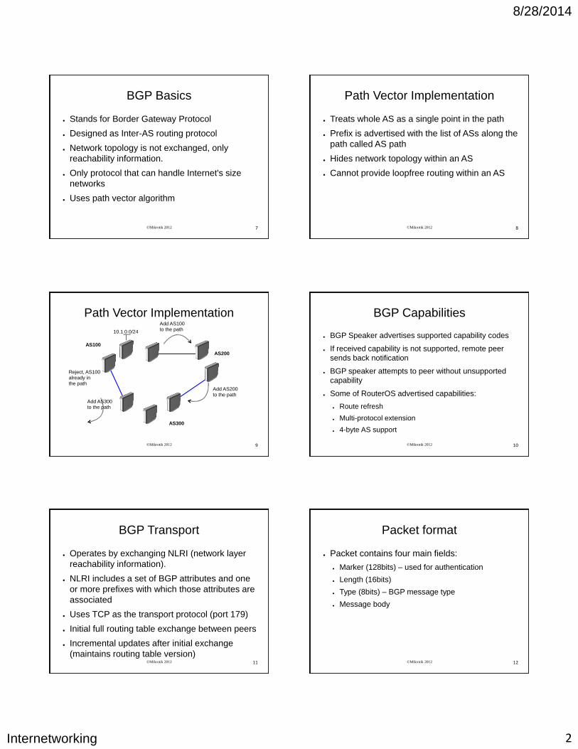
Path Vector Implementation
AS300
AS200
AS100
10.1.0.0/24
Add AS100 to the path
Add AS300 to the path
Reject, AS100 already in the path
Add AS200 to the path
©Mikrotik 2012 10
BGP Capabilities
● BGP Speaker advertises supported capability codes
● If received capability is not supported, remote peer
sends back notification
● BGP speaker attempts to peer without unsupported
capability
● Some of RouterOS advertised capabilities:
● Route refresh
● Multi-protocol extension
● 4-byte AS support
©Mikrotik 2012 11
BGP Transport
● Operates by exchanging NLRI (network layer
reachability information).
● NLRI includes a set of BGP attributes and one
or more prefixes with which those attributes are
associated
● Uses TCP as the transport protocol (port 179)
● Initial full routing table exchange between peers
● Incremental updates after initial exchange
(maintains routing table version) ©Mikrotik 2012 12
Packet format
● Packet contains four main fields:
● Marker (128bits) – used for authentication
● Length (16bits)
● Type (8bits) – BGP message type
● Message body
8/28/2014
Internetworking 3
©Mikrotik 2012 13
BGP message types ● Four message types:
● Open – First message sent after TCP connection
establishment, contains capability list. Confirmed by
keepalive.
● Keepalive – does not contain data, sent to keep
hold timer from expiring
● Update – actual route updates. Contains:
– NLRI
– Path attributes
● Notification – sent when error condition occurs,
contains error code and sub-code
©Mikrotik 2012 14
AS100 AS200
AS100
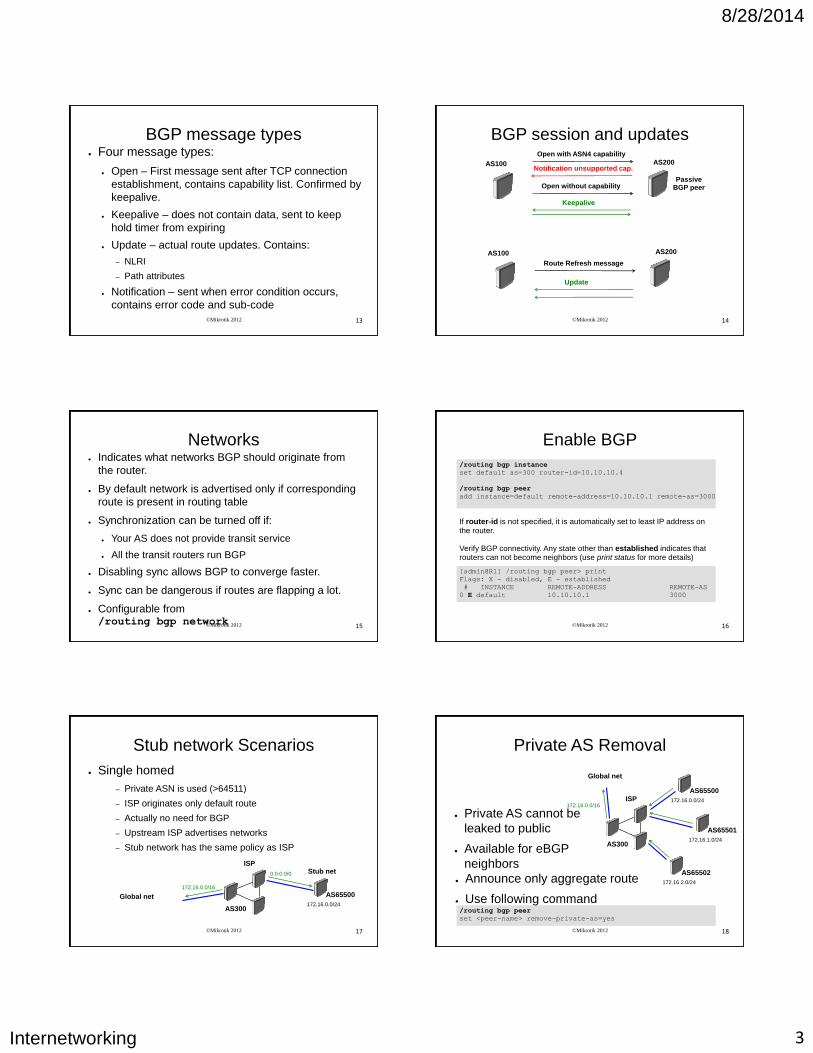
BGP session and updates
Keepalive
Open with ASN4 capability
Notification unsupported cap.
Passive BGP peer Open without capability
Update
Route Refresh message
AS200
©Mikrotik 2012 15
Networks ● Indicates what networks BGP should originate from
the router.
● By default network is advertised only if corresponding
route is present in routing table
● Synchronization can be turned off if:
● Your AS does not provide transit service
● All the transit routers run BGP
● Disabling sync allows BGP to converge faster.
● Sync can be dangerous if routes are flapping a lot.
● Configurable from /routing bgp network ©Mikrotik 2012 16
Enable BGP
/routing bgp instance
set default as=300 router-id=10.10.10.4
/routing bgp peer
add instance=default remote-address=10.10.10.1 remote-as=3000
If router-id is not specified, it is automatically set to least IP address on the router. Verify BGP connectivity. Any state other than established indicates that routers can not become neighbors (use print status for more details)
[admin@R1] /routing bgp peer> print
Flags: X - disabled, E - established
# INSTANCE REMOTE-ADDRESS REMOTE-AS
0 E default 10.10.10.1 3000
©Mikrotik 2012 17
Stub network Scenarios
● Single homed
– Private ASN is used (>64511)
– ISP originates only default route
– Actually no need for BGP
– Upstream ISP advertises networks
– Stub network has the same policy as ISP
AS300
Stub net
172.16.0.0/24
Global net
ISP
172.16.0.0/16
0.0.0.0/0
AS65500
©Mikrotik 2012 18
Private AS Removal
● Private AS cannot be
leaked to public
● Available for eBGP
neighbors
AS300 172.16.1.0/24
Global net
ISP 172.16.0.0/16
AS65501
172.16.0.0/24
AS65500
172.16.2.0/24
AS65502 ● Announce only aggregate route
● Use following command /routing bgp peer
set <peer-name> remove-private-as=yes
8/28/2014
Internetworking 4
©Mikrotik 2012 19
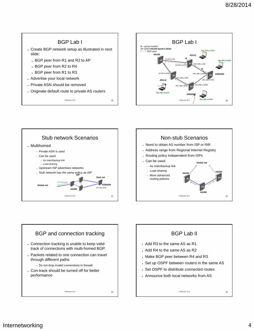
BGP Lab I
● Create BGP network setup as illustrated in next
slide:
● BGP peer from R1 and R2 to AP
● BGP peer from R2 to R4
● BGP peer from R1 to R3
● Advertise your local network
● Private ASN should be removed
● Originate default route to private AS routers
©Mikrotik 2012 20
BGP Lab I X – group number AP SSID=AS100 band=2.4Ghz BGP peer
192.168.x3.0/24
R3
R4
AS100
AP
192.168.x1.0/24
R1
192.168.x2.0/24
R2
10.20.0.1/24
10.20.0.x1/24 192.168.x.1/30
192.168.x.2/30
192.168.x.5/30
192.168.x.6/30
10.20.0.x2/24
192.168.x4.0/24
192.168.x.9/30
192.168.x.10/30
AS65500
AS65500
AS1x1
AS1x2
©Mikrotik 2012 21
Stub network Scenarios
● Multihomed
– Private ASN is used
– Can be used:
● As main/backup link
● Load sharing
– Upstream ISP advertises networks
– Stub network has the same policy as ISP
AS300
Stub net
172.16.0.0/24
Global net
ISP
172.16.0.0/16
AS65500
©Mikrotik 2012 22
Non-stub Scenarios ● Need to obtain AS number from ISP or RIR
● Address range from Regional Internet Registry
● Routing policy independent from ISPs
● Can be used:
– As main/backup link
– Load sharing
– More advanced
routing policies
AS300
AS100
R1 R3
R2
AS200
Global net
©Mikrotik 2012 23
BGP and connection tracking
● Connection tracking is unable to keep valid
track of connections with multi-homed BGP.
● Packets related to one connection can travel
through different paths
– Do not drop invalid connections in firewall
● Con-track should be turned off for better
performance
©Mikrotik 2012 24
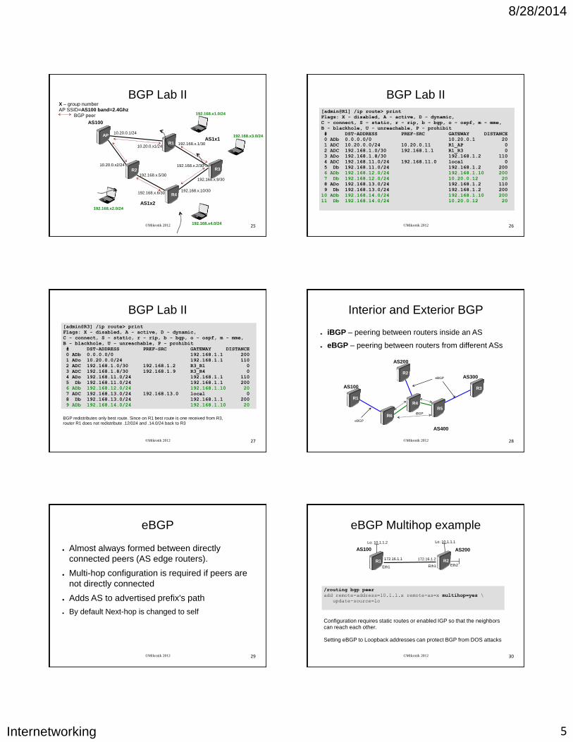
BGP Lab II
● Add R3 to the same AS as R1
● Add R4 to the same AS as R2
● Make BGP peer between R4 and R3
● Set up OSPF between routers in the same AS
● Set OSPF to distribute connected routes
● Announce both local networks from AS
8/28/2014
Internetworking 5
©Mikrotik 2012 25
BGP Lab II X – group number AP SSID=AS100 band=2.4Ghz BGP peer
192.168.x3.0/24
R3
R4
AS100
AP
192.168.x1.0/24
R1
192.168.x2.0/24
R2
10.20.0.1/24
10.20.0.x1/24 192.168.x.1/30
192.168.x.2/30
192.168.x.5/30
192.168.x.6/30
10.20.0.x2/24
192.168.x4.0/24
192.168.x.9/30
192.168.x.10/30
AS1x1
AS1x2
©Mikrotik 2012 26
BGP Lab II
[admin@R1] /ip route> print
Flags: X - disabled, A - active, D - dynamic,
C - connect, S - static, r - rip, b - bgp, o - ospf, m - mme,
B - blackhole, U - unreachable, P - prohibit
# DST-ADDRESS PREF-SRC GATEWAY DISTANCE
0 ADb 0.0.0.0/0 10.20.0.1 20
1 ADC 10.20.0.0/24 10.20.0.11 R1_AP 0
2 ADC 192.168.1.0/30 192.168.1.1 R1_R3 0
3 ADo 192.168.1.8/30 192.168.1.2 110
4 ADC 192.168.11.0/24 192.168.11.0 local 0
5 Db 192.168.11.0/24 192.168.1.2 200
6 ADb 192.168.12.0/24 192.168.1.10 200
7 Db 192.168.12.0/24 10.20.0.12 20
8 ADo 192.168.13.0/24 192.168.1.2 110
9 Db 192.168.13.0/24 192.168.1.2 200
10 ADb 192.168.14.0/24 192.168.1.10 200
11 Db 192.168.14.0/24 10.20.0.12 20
©Mikrotik 2012 27
BGP Lab II
[admin@R3] /ip route> print
Flags: X - disabled, A - active, D - dynamic,
C - connect, S - static, r - rip, b - bgp, o - ospf, m - mme,
B - blackhole, U - unreachable, P - prohibit
# DST-ADDRESS PREF-SRC GATEWAY DISTANCE
0 ADb 0.0.0.0/0 192.168.1.1 200
1 ADo 10.20.0.0/24 192.168.1.1 110
2 ADC 192.168.1.0/30 192.168.1.2 R3_R1 0
3 ADC 192.168.1.8/30 192.168.1.9 R3_R4 0
4 ADo 192.168.11.0/24 192.168.1.1 110
5 Db 192.168.11.0/24 192.168.1.1 200
6 ADb 192.168.12.0/24 192.168.1.10 20
7 ADC 192.168.13.0/24 192.168.13.0 local 0
8 Db 192.168.13.0/24 192.168.1.1 200
9 ADb 192.168.14.0/24 192.168.1.10 20
BGP redistributes only best route. Since on R1 best route is one received from R3, router R1 does not redistribute .12/024 and .14.0/24 back to R3
©Mikrotik 2012 28
Interior and Exterior BGP
● iBGP – peering between routers inside an AS
● eBGP – peering between routers from different ASs
AS400
AS300
AS100
eBGP
eBGP
iBGP
R1
R3
R5
R6
AS200
R2
R4
©Mikrotik 2012 29
eBGP
● Almost always formed between directly
connected peers (AS edge routers).
● Multi-hop configuration is required if peers are
not directly connected
● Adds AS to advertised prefix's path
● By default Next-hop is changed to self
©Mikrotik 2012 30
eBGP Multihop example
/routing bgp peer
add remote-address=10.1.1.x remote-as=x multihop=yes \
update-source=lo
Configuration requires static routes or enabled IGP so that the neighbors can reach each other. Setting eBGP to Loopback addresses can protect BGP from DOS attacks
R2 R1
Lo: 10.1.1.1 Lo: 10.1.1.2
Eth1 Eth1 Eth2
AS100 AS200
172.16.1.1 172.16.1.2
8/28/2014
Internetworking 6
©Mikrotik 2012 31
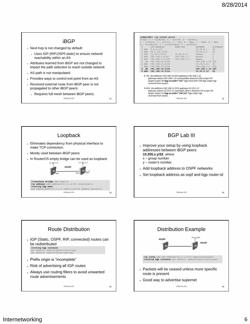
iBGP ● Next-hop is not changed by default:
● Uses IGP (RIP,OSPF,static) to ensure network
reachability within an AS
● Attributes learned from iBGP are not changed to
impact the path selection to reach outside network
● AS path is not manipulated
● Provides ways to control exit point from an AS
● Received external route from iBGP peer is not
propagated to other iBGP peers:
● Requires full mesh between iBGP peers.
©Mikrotik 2012 32
[admin@R1] /ip route> print
Flags: X - disabled, A - active, D - dynamic,
C - connect, S - static, r - rip, b - bgp, o - ospf, m - mme,
B - blackhole, U - unreachable, P - prohibit
# DST-ADDRESS PREF-SRC GATEWAY DISTANCE
0 ADb 0.0.0.0/0 10.20.0.1 20
1 ADb 10.1.101.0/24 10.20.0.1 20
2 ADC 10.20.0.0/24 10.20.0.11 ether1 0
3 ADC 192.168.1.0/30 192.168.1.1 ether2 0
4 ADC 192.168.11.0/24 192.168.11.1 dummy 0
5 Db 192.168.12.0/24 192.168.1.10 200
6 ADb 192.168.12.0/24 10.20.0.12 20
7 ADb 192.168.13.0/24 192.168.1.2 200
8 Db 192.168.14.0/24 192.168.1.10 200
9 ADb 192.168.14.0/24 10.20.0.12 20
8 Db dst-address=192.168.14.0/24 gateway=192.168.1.10 gateway-status=192.168.1.10 unreachable distance=200 scope=40 target-scope=30 bgp-as-path="112" bgp-local-pref=100 bgp-origin=igp received-from=peer2 9 ADb dst-address=192.168.14.0/24 gateway=10.20.0.12 gateway-status=10.20.0.12 reachable ether1 distance=20 scope=40 target-scope=10 bgp-as-path="100,112" bgp-origin=igp received-from=peer1
©Mikrotik 2012 33
Loopback
● Eliminates dependency from physical interface to
make TCP connection.
● Mostly used between iBGP peers
● In RouterOS empty bridge can be used as loopback
R2 R1
Lo: 10.1.1.1 Lo: 10.1.1.2
Eth1 Eth1 Eth2
AS100
/interface bridge add name=lo
/ip address add address=10.1.1.x/32 interface=lo
/routing bgp peer
add remote-peer=10.1.1.x remote-as=100 update-source=lo
©Mikrotik 2012 34
BGP Lab III
● Improve your setup by using loopback
addresses between iBGP peers 10.255.x.y/32, where
x – group number
y – router's number
● Add loopback address to OSPF networks
● Set loopback address as ospf and bgp router-id
©Mikrotik 2012 35
Route Distribution
● IGP (Static, OSPF, RIP, connected) routes can
be redistributed
● Prefix origin is “incomplete”
● Risk of advertising all IGP routes
● Always use routing filters to avoid unwanted
route advertisements
/routing bgp instance
set default redistribute-static=yes
set default redistribute-ospf=yes
©Mikrotik 2012 36
Distribution Example
R2 R1
10.1.1.0/24
AS100
AS200
/ip route add dst-address=10.1.1.0/24 type=unreachable
/routing bgp instance set default redistribute-static=yes
● Packets will be ceased unless more specific
route is present
● Good way to advertise supernet
8/28/2014
Internetworking 7
©Mikrotik 2012 37
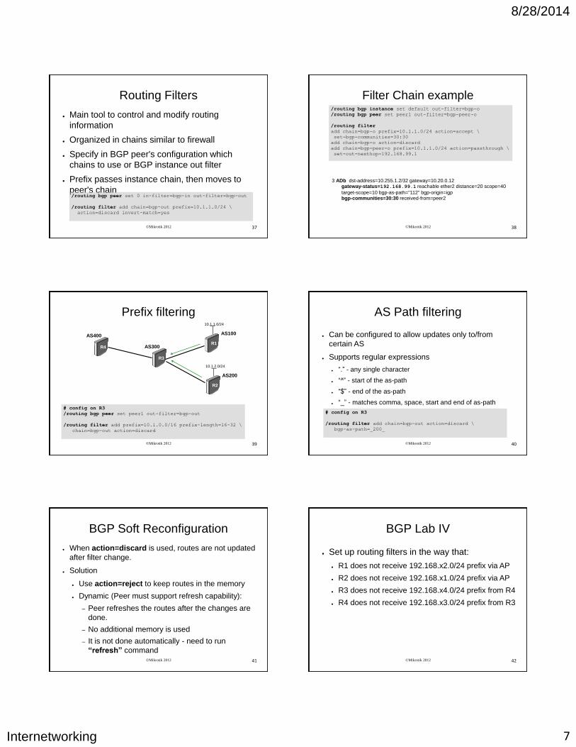
Routing Filters
● Main tool to control and modify routing
information
● Organized in chains similar to firewall
● Specify in BGP peer's configuration which
chains to use or BGP instance out filter
● Prefix passes instance chain, then moves to
peer's chain /routing bgp peer set 0 in-filter=bgp-in out-filter=bgp-out
/routing filter add chain=bgp-out prefix=10.1.1.0/24 \
action=discard invert-match=yes
©Mikrotik 2012 38
Filter Chain example /routing bgp instance set default out-filter=bgp-o
/routing bgp peer set peer1 out-filter=bgp-peer-o
/routing filter
add chain=bgp-o prefix=10.1.1.0/24 action=accept \
set-bgp-communities=30:30
add chain=bgp-o action=discard
add chain=bgp-peer-o prefix=10.1.1.0/24 action=passthrough \
set-out-nexthop=192.168.99.1
3 ADb dst-address=10.255.1.2/32 gateway=10.20.0.12 gateway-status=192.168.99.1 reachable ether2 distance=20 scope=40
target-scope=10 bgp-as-path="112" bgp-origin=igp bgp-communities=30:30 received-from=peer2
©Mikrotik 2012 39
Prefix filtering
# config on R3
/routing bgp peer set peer1 out-filter=bgp-out
/routing filter add prefix=10.1.0.0/16 prefix-length=16-32 \
chain=bgp-out action=discard
R1
R3
10.1.1.0/24
AS100
AS300 R4
AS400
R2
10.1.2.0/24
AS200
©Mikrotik 2012 40
AS Path filtering
● Can be configured to allow updates only to/from
certain AS
● Supports regular expressions
● “.” - any single character
● “^” - start of the as-path
● “$” - end of the as-path
● “_” - matches comma, space, start and end of as-path
# config on R3
/routing filter add chain=bgp-out action=discard \
bgp-as-path=_200_
©Mikrotik 2012 41
BGP Soft Reconfiguration
● When action=discard is used, routes are not updated
after filter change.
● Solution
● Use action=reject to keep routes in the memory
● Dynamic (Peer must support refresh capability):
– Peer refreshes the routes after the changes are
done.
– No additional memory is used
– It is not done automatically - need to run
“refresh” command ©Mikrotik 2012 42
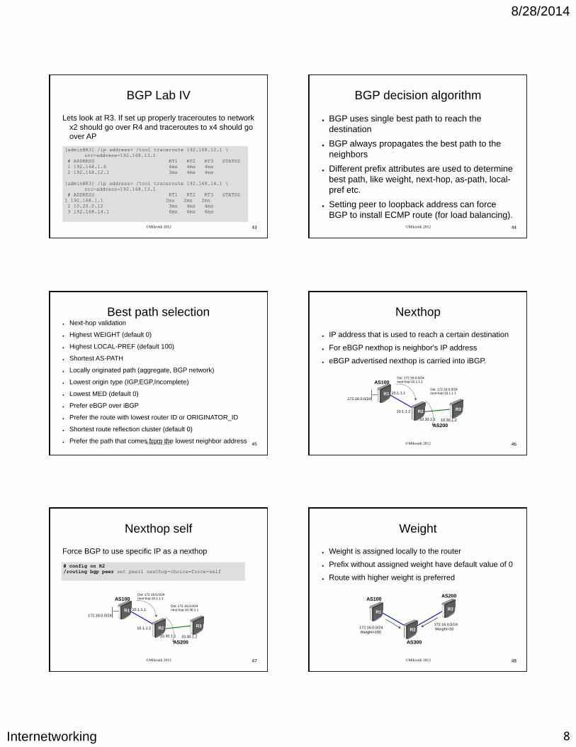
BGP Lab IV
● Set up routing filters in the way that:
● R1 does not receive 192.168.x2.0/24 prefix via AP
● R2 does not receive 192.168.x1.0/24 prefix via AP
● R3 does not receive 192.168.x4.0/24 prefix from R4
● R4 does not receive 192.168.x3.0/24 prefix from R3
8/28/2014
Internetworking 8
©Mikrotik 2012 43
BGP Lab IV
[admin@R3] /ip address> /tool traceroute 192.168.12.1 \
src-address=192.168.13.1
# ADDRESS RT1 RT2 RT3 STATUS
1 192.168.1.6 4ms 4ms 4ms
2 192.168.12.1 3ms 4ms 4ms
[admin@R3] /ip address> /tool traceroute 192.168.14.1 \
src-address=192.168.13.1
# ADDRESS RT1 RT2 RT3 STATUS
1 192.168.1.1 2ms 2ms 2ms
2 10.20.0.12 3ms 4ms 4ms
3 192.168.14.1 6ms 6ms 6ms
Lets look at R3. If set up properly traceroutes to network
x2 should go over R4 and traceroutes to x4 should go
over AP
©Mikrotik 2012 44
BGP decision algorithm
● BGP uses single best path to reach the
destination
● BGP always propagates the best path to the
neighbors
● Different prefix attributes are used to determine
best path, like weight, next-hop, as-path, local-
pref etc.
● Setting peer to loopback address can force
BGP to install ECMP route (for load balancing).
©Mikrotik 2012 45
Best path selection ● Next-hop validation
● Highest WEIGHT (default 0)
● Highest LOCAL-PREF (default 100)
● Shortest AS-PATH
● Locally originated path (aggregate, BGP network)
● Lowest origin type (IGP,EGP,Incomplete)
● Lowest MED (default 0)
● Prefer eBGP over iBGP
● Prefer the route with lowest router ID or ORIGINATOR_ID
● Shortest route reflection cluster (default 0)
● Prefer the path that comes from the lowest neighbor address ©Mikrotik 2012 46
Nexthop
● IP address that is used to reach a certain destination
● For eBGP nexthop is neighbor's IP address
● eBGP advertised nexthop is carried into iBGP.
AS200
AS100
R1
R3 R2
172.16.0.0/24
10.1.1.1
10.1.1.2
Dst: 172.16.0.0/24 next-hop:10.1.1.1
Dst: 172.16.0.0/24 next-hop:10.1.1.1
10.30.1.1 10.30.1.2
©Mikrotik 2012 47
Nexthop self
Force BGP to use specific IP as a nexthop
AS200
AS100
R1
R3 R2
172.16.0.0/24
10.1.1.1
10.1.1.2
Dst: 172.16.0.0/24 next-hop:10.1.1.1
Dst: 172.16.0.0/24 next-hop:10.30.1.1
10.30.1.1 10.30.1.2
# config on R2
/routing bgp peer set peer1 nexthop-choice=force-self
©Mikrotik 2012 48
Weight
● Weight is assigned locally to the router
● Prefix without assigned weight have default value of 0
● Route with higher weight is preferred
AS300
AS100
R1 R3
R2 172.16.0.0/24 Weight=100
AS200
172.16.0.0/24 Weight=50
8/28/2014
Internetworking 9
©Mikrotik 2012 49
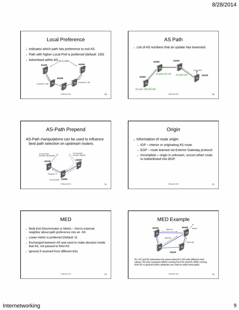
Local Preference
● Indicates which path has preference to exit AS
● Path with higher Local Pref is preferred (default: 100)
● Advertised within AS
AS300
AS100
R1
R4 R2
R3
AS200
R5
10.1.1.0/24
Local-pref = 200 Local-pref = 100
©Mikrotik 2012 50
AS Path
● List of AS numbers that an update has traversed.
R1
R2
10.1.1.0/24
AS100
AS200
R3
AS300
R4
AS400
AS-path: 300,200,100
AS-path:200,100 AS-path:100
©Mikrotik 2012 51
AS-Path Prepend
AS-Path manipulations can be used to influence
best path selection on upstream routers.
AS300
AS100
R1 R3
R2
AS200
172.16.0.0/24
172.16.0.0/24 AS-Path: 200,300
172.16.0.0/24 AS-Path: 100,300,300
Prepend = 2
©Mikrotik 2012 52
Origin
● Information of route origin:
● IGP – interior or originating AS route.
● EGP – route learned via Exterior Gateway protocol
● Incomplete – origin is unknown, occurs when route
is redistributed into BGP.
©Mikrotik 2012 53
MED
● Multi Exit Discriminator or Metric – hint to external
neighbor about path preference into an AS
● Lower metric is preferred (Default: 0)
● Exchanged between AS and used to make decision inside
that AS, not passed to third AS.
● Ignored if received from different ASs
©Mikrotik 2012 54
MED Example
R1, R2 and R3 advertises the same network to R4 with different med values. R4 only compares MEDs coming from R2 and R3, MED coming from R1 is ignored (other attributes are used to select best path).
AS200
AS100
R1
R3 R2
AS300
R4
Med=10
Med=50
Med=100
Med=0
8/28/2014
Internetworking 10
©Mikrotik 2012 55
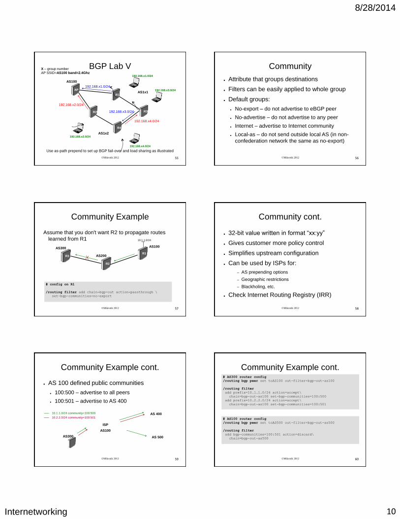
BGP Lab V X – group number AP SSID=AS100 band=2.4Ghz
192.168.x3.0/24
R3
R4
AS100
AP
192.168.x1.0/24
R1
192.168.x2.0/24
R2
192.168.x4.0/24
AS1x1
AS1x2
192.168.x4.0/24
192.168.x2.0/24
192.168.x1.0/24
192.168.x3.0/24
Use as-path prepend to set up BGP fail-over and load sharing as illustrated
©Mikrotik 2012 56
Community
● Attribute that groups destinations
● Filters can be easily applied to whole group
● Default groups:
● No-export – do not advertise to eBGP peer
● No-advertise – do not advertise to any peer
● Internet – advertise to Internet community
● Local-as – do not send outside local AS (in non-
confederation network the same as no-export)
©Mikrotik 2012 57
Community Example
Assume that you don't want R2 to propagate routes
learned from R1
# config on R1
/routing filter add chain=bgp-out action=passthrough \
set-bgp-communities=no-export
R1
R2
10.1.1.0/24
AS100
AS200 R3
AS300
©Mikrotik 2012 58
Community cont.
● 32-bit value written in format “xx:yy”
● Gives customer more policy control
● Simplifies upstream configuration
● Can be used by ISPs for:
– AS prepending options
– Geographic restrictions
– Blackholing, etc.
● Check Internet Routing Registry (IRR)
©Mikrotik 2012 59
Community Example cont.
● AS 100 defined public communities
● 100:500 – advertise to all peers
● 100:501 – advertise to AS 400
ISP
AS100
AS 400
AS 500
10.1.1.0/24 community=100:500
10.2.2.0/24 community=100:501
AS300
©Mikrotik 2012 60
Community Example cont. # AS300 router config
/routing bgp peer set toAS100 out-filter=bgp-out-as100
/routing filter
add prefix=10.1.1.0/24 action=accept\
chain=bgp-out-as100 set-bgp-communities=100:500
add prefix=10.2.2.0/24 action=accept\
chain=bgp-out-as100 set-bgp-communities=100:501
# AS100 router config
/routing bgp peer set toAS500 out-filter=bgp-out-as500
/routing filter
add bgp-communities=100:501 action=discard\
chain=bgp-out-as500
8/28/2014
Internetworking 11
©Mikrotik 2012 61
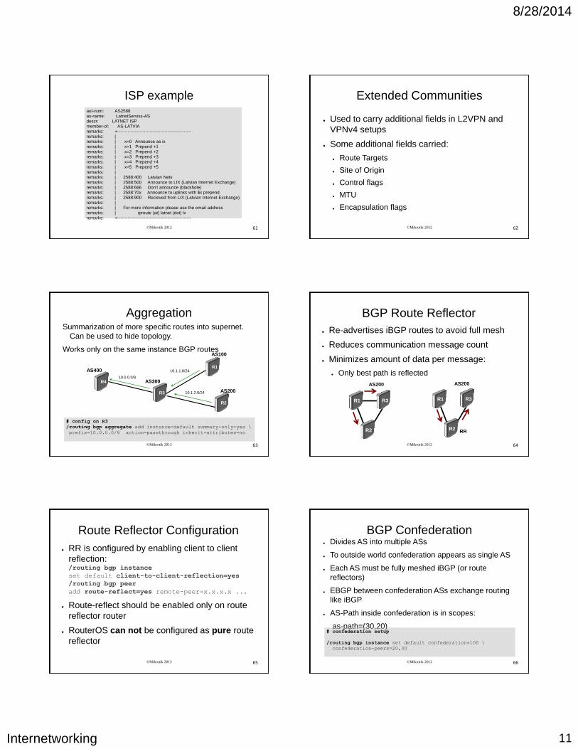
ISP example aut-num: AS2588 as-name: LatnetServiss-AS descr: LATNET ISP member-of: AS-LATVIA remarks: +-------------------------------------------------- remarks: | remarks: | x=0 Announce as is remarks: | x=1 Prepend +1 remarks: | x=2 Prepend +2 remarks: | x=3 Prepend +3 remarks: | x=4 Prepend +4 remarks: | x=5 Prepend +5 remarks: | remarks: | 2588:400 Latvian Nets remarks: | 2588:500 Announce to LIX (Latvian Internet Exchange) remarks: | 2588:666 Don't announce (blackhole) remarks: | 2588:70x Announce to uplinks with $x prepend remarks: | 2588:900 Recieved from LIX (Latvian Internet Exchange) remarks: | remarks: | For more information please use the email address remarks: | iproute (at) latnet (dot) lv remarks: +--------------------------------------------------
©Mikrotik 2012 62
Extended Communities
● Used to carry additional fields in L2VPN and
VPNv4 setups
● Some additional fields carried:
● Route Targets
● Site of Origin
● Control flags
● MTU
● Encapsulation flags
©Mikrotik 2012 63
Aggregation Summarization of more specific routes into supernet.
Can be used to hide topology.
Works only on the same instance BGP routes
R1
R3
10.1.1.0/24
AS100
AS300 R4
AS400
R2
10.1.2.0/24 AS200
10.0.0.0/8
# config on R3
/routing bgp aggregate add instance=default summary-only=yes \
prefix=10.0.0.0/8 action=passthrough inherit-attributes=no
©Mikrotik 2012 64
BGP Route Reflector
● Re-advertises iBGP routes to avoid full mesh
● Reduces communication message count
● Minimizes amount of data per message:
● Only best path is reflected
R1
R2
R3
AS200
RR
R1
R2
R3
AS200
©Mikrotik 2012 65
Route Reflector Configuration
● RR is configured by enabling client to client
reflection: /routing bgp instance
set default client-to-client-reflection=yes
/routing bgp peer
add route-reflect=yes remote-peer=x.x.x.x ...
● Route-reflect should be enabled only on route
reflector router
● RouterOS can not be configured as pure route
reflector
©Mikrotik 2012 66
BGP Confederation ● Divides AS into multiple ASs
● To outside world confederation appears as single AS
● Each AS must be fully meshed iBGP (or route
reflectors)
● EBGP between confederation ASs exchange routing
like iBGP
● AS-Path inside confederation is in scopes:
as-path=(30,20)
# confederation setup
/routing bgp instance set default confederation=100 \
confederation-peers=20,30
8/28/2014
Internetworking 12
©Mikrotik 2012 67
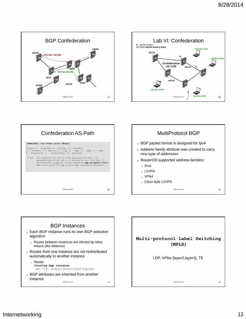
BGP Confederation
R9
R5
AS300
AS100
R8
AS200
R6
R7
R1
R2
R3 R4
AS10
AS20
AS30 AS400
AS-Path: 100,300
AS-Path:(20,30)
©Mikrotik 2012 68
Lab VI: Confederation X – group number AP SSID=AS100 band=2.4Ghz
192.168.x3.0/24
R3
R4
AS100
AP
192.168.x1.0/24
R1
192.168.x2.0/24
R2
192.168.x4.0/24
AS1x1
AS1x2
Confederation AS xx00
©Mikrotik 2012 69
[admin@R1] /ip route> print detail
Flags: X - disabled, A - active, D - dynamic,
C - connect, S - static, r - rip, b - bgp, o - ospf, m - mme,
B - blackhole, U - unreachable, P - prohibit
...
8 ADb dst-address=192.168.12.0/24 gateway=192.168.1.10
gateway-status=192.168.1.10 recursive via 192.168.1.2
distance=200 scope=40 target-scope=30 bgp-as-path="(112)"
bgp-local-pref=100 bgp-origin=igp received-from=peer2
Confederation AS-Path
©Mikrotik 2012 70
MultiProtocol BGP
● BGP packet format is designed for Ipv4
● Address family attribute was created to carry
new type of addresses.
● RouterOS supported address families:
● IPv6
● L2VPN
● VPN4
● Cisco style L2VPN
©Mikrotik 2012 71
BGP Instances ● Each BGP instance runs its own BGP selection
algorithm
● Routes between instances are elected by other
means (like distance)
● Routes from one instance are not redistributed
automatically to another instance
● Needs: /routing bgp instance
set <id> redistribute-other-bgp=yes
● BGP attributes are inherited from another
instance ©Mikrotik 2012 72
Multi-protocol Label Switching
(MPLS)
LDP, VPNs (layer2,layer3), TE
8/28/2014
Internetworking 13
©Mikrotik 2012 73
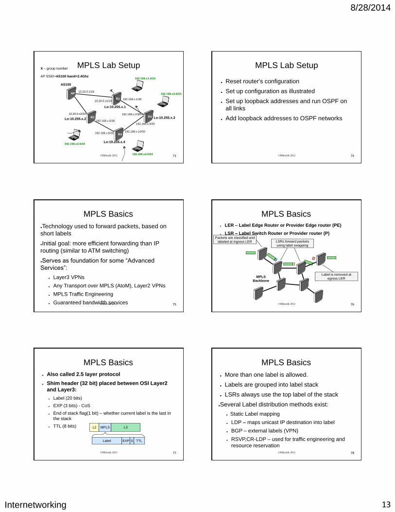
MPLS Lab Setup X – group number AP SSID=AS100 band=2.4Ghz
192.168.x3.0/24
R3
R4
AS100
AP
192.168.x1.0/24
R1
192.168.x2.0/24
R2
10.20.0.1/24
10.20.0.x1/24 192.168.x.1/30
192.168.x.2/30
192.168.x.5/30
192.168.x.6/30
10.20.0.x2/24
192.168.x4.0/24
192.168.x.9/30
192.168.x.10/30
Lo:10.255.x.1
Lo:10.255.x.2
Lo:10.255.x.4
Lo:10.255.x.3
©Mikrotik 2012 74
MPLS Lab Setup
● Reset router's configuration
● Set up configuration as illustrated
● Set up loopback addresses and run OSPF on
all links
● Add loopback addresses to OSPF networks
©Mikrotik 2012 75
MPLS Basics
●Technology used to forward packets, based on
short labels
●Initial goal: more efficient forwarding than IP
routing (similar to ATM switching)
●Serves as foundation for some “Advanced
Services”:
● Layer3 VPNs
● Any Transport over MPLS (AtoM), Layer2 VPNs
● MPLS Traffic Engineering
● Guaranteed bandwidth services ©Mikrotik 2012 76
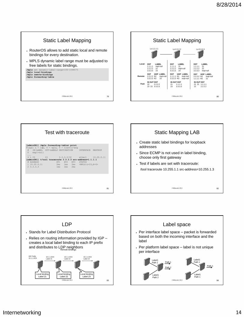
MPLS Basics
● LER – Label Edge Router or Provider Edge router (PE)
● LSR – Label Switch Router or Provider router (P)
MPLS Backbone
Packets are classified and labeled at ingress LER LSRs forward packets
using label swapping
Label is removed at egress LER
©Mikrotik 2012 77
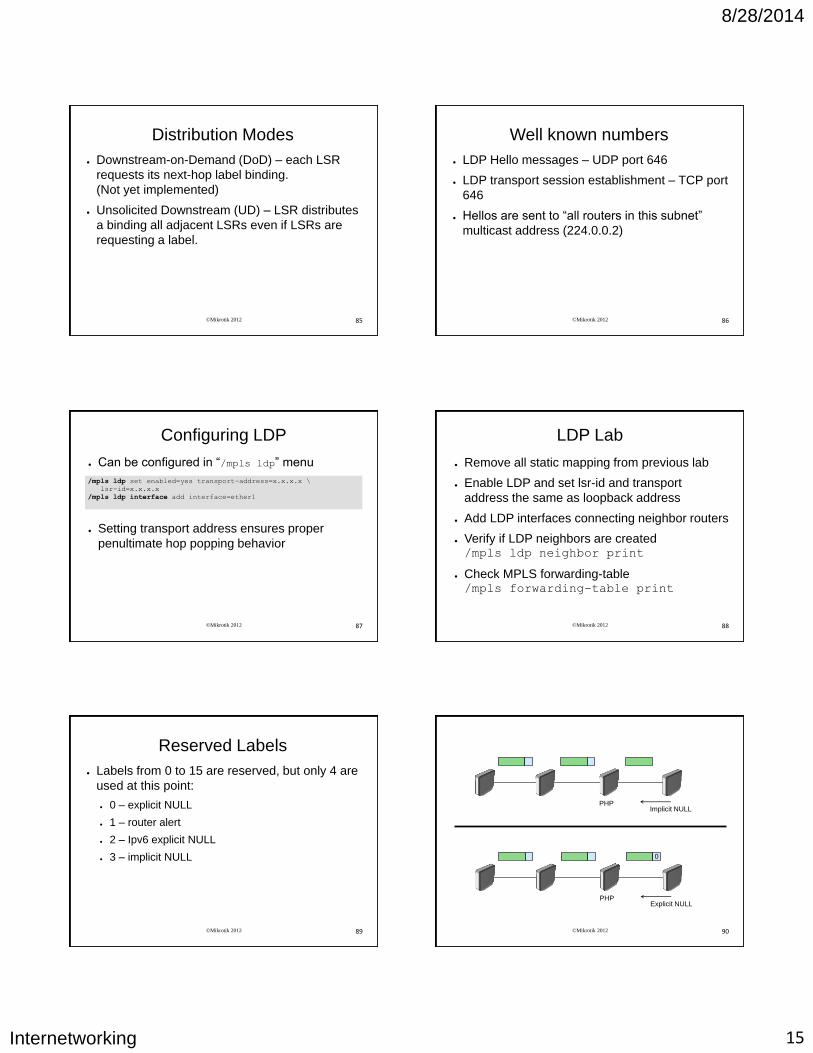
MPLS Basics
● Also called 2.5 layer protocol
● Shim header (32 bit) placed between OSI Layer2
and Layer3:
● Label (20 bits)
● EXP (3 bits) - CoS
● End of stack flag(1 bit) – whether current label is the last in
the stack
● TTL (8 bits) L3 MPLS L2
TTL S EXP Label
©Mikrotik 2012 78
MPLS Basics
● More than one label is allowed.
● Labels are grouped into label stack
● LSRs always use the top label of the stack
●Several Label distribution methods exist:
● Static Label mapping
● LDP – maps unicast IP destination into label
● BGP – external labels (VPN)
● RSVP,CR-LDP – used for traffic engineering and
resource reservation
8/28/2014
Internetworking 14
©Mikrotik 2012 79
Static Label Mapping
● RouterOS allows to add static local and remote
bindings for every destination.
● MPLS dynamic label range must be adjusted to
free labels for static bindings. /mpls set dynamic-label-range=100-1048575
/mpls local-bindings
/mpls remote-bindings
/mpls forwarding-table
©Mikrotik 2012 80
Static Label Mapping
Lo:1.1.1.1 Lo:2.2.2.2 Lo:3.3.3.3
Local:
Remote:
Fwd:
DST LABEL 1.1.1.1 impl-null 2.2.2.2 22 3.3.3.3 23
DST LABEL 1.1.1.1 21 2.2.2.2 impl-null 3.3.3.3 23
DST LABEL 1.1.1.1 21 2.2.2.2 22 3.3.3.3 impl-null
DST HOP LABEL 2.2.2.2 R2 impl-null 3.3.3.3 R2 23
DST HOP LABEL 1.1.1.1 R1 impl-null 3.3.3.3 R3 impl-null
DST HOP LABEL 2.2.2.2 R2 impl-null 1.1.1.1 R2 21
IN OUT DST 22 2.2.2.2 23 23 3.3.3.3
IN OUT DST 21 1.1.1.1 23 3.3.3.3
IN OUT DST 21 21 1.1.1.1 22 2.2.2.2
©Mikrotik 2012 81
Test with traceroute
[admin@R1] /mpls forwarding-table> print
Flags: L - ldp, V - vpls, T - traffic-eng
# IN-LABEL OUT-LABELS DESTINATION INTERFACE NEXTHOP
0 expl-null
...
4 L 23 23 3.3.3.3/32 ether1 10.20.0.11
[admin@R1] >/tool traceroute 3.3.3.3 src-address=1.1.1.1
# ADDRESS RT1 RT2 RT3 STATUS
1 10.20.0.11 2ms 1ms 2ms <MPLS:L=23,E=0>
2 3.3.3.3 1ms 1ms 2ms
©Mikrotik 2012 82
Static Mapping LAB
● Create static label bindings for loopback
addresses
● Since ECMP is not used in label binding,
choose only first gateway
● Test if labels are set with traceroute:
/tool traceroute 10.255.1.1 src-address=10.255.1.3
©Mikrotik 2012 83
LDP
● Stands for Label Distribution Protocol
● Relies on routing information provided by IGP –
creates a local label binding to each IP prefix
and distributes to LDP neighbors
10.1.1.0/24 Label 22
Local binding Label 21
10.1.1.0/24 Label 21
10.1.1.0/24 Label 23
Local binding Label 22
Local binding Label 23
IGP Prefix 10.1.1.0/24
Remote bindings
©Mikrotik 2012 84
Label space
● Per interface label space – packet is forwarded
based on both the incoming interface and the
label
● Per platform label space – label is not unique
per interface
Path 1
Path 2
Label1 Path 1
Label1 Path 2
Path 1
Label1 Path 1
Label1 Path 1
8/28/2014
Internetworking 15
©Mikrotik 2012 85
Distribution Modes
● Downstream-on-Demand (DoD) – each LSR
requests its next-hop label binding.
(Not yet implemented)
● Unsolicited Downstream (UD) – LSR distributes
a binding all adjacent LSRs even if LSRs are
requesting a label.
©Mikrotik 2012 86
Well known numbers
● LDP Hello messages – UDP port 646
● LDP transport session establishment – TCP port
646
● Hellos are sent to “all routers in this subnet”
multicast address (224.0.0.2)
©Mikrotik 2012 87
Configuring LDP
● Can be configured in “/mpls ldp” menu
● Setting transport address ensures proper
penultimate hop popping behavior
/mpls ldp set enabled=yes transport-address=x.x.x.x \
lsr-id=x.x.x.x
/mpls ldp interface add interface=ether1
©Mikrotik 2012 88
LDP Lab
● Remove all static mapping from previous lab
● Enable LDP and set lsr-id and transport
address the same as loopback address
● Add LDP interfaces connecting neighbor routers
● Verify if LDP neighbors are created /mpls ldp neighbor print
● Check MPLS forwarding-table /mpls forwarding-table print
©Mikrotik 2012 89
Reserved Labels
● Labels from 0 to 15 are reserved, but only 4 are
used at this point:
● 0 – explicit NULL
● 1 – router alert
● 2 – Ipv6 explicit NULL
● 3 – implicit NULL
©Mikrotik 2012 90
Implicit NULL PHP
0
Explicit NULL PHP

8/28/2014
Internetworking 16
©Mikrotik 2012 91
Penultimate Hop Popping
● Router is egress point for network that is
directly connected to it, next hop for traffic is not
MPLS router
● Advertised with “implicit null” label
● Penultimate hop popping ensures that routers
do not have to do unnecessary label lookup
when it is known in advance that router will
have to route packet
©Mikrotik 2012 92
Explicit NULL
● If configured, penultimate LSR forwards packet
with NULL label, instead of popping stack.
● Useful to preserve QoS
● Not required if stack contains at least two labels
(inner label can still carry QoS value)
● Implicit NULL is used by default
©Mikrotik 2012 93
MPLS Traceroute
● ICMP error messages are switched further
along LSP
● It will give false increase in latency for that hop
Label: 12
R1 R2 R3 R4
Label: 34
Label: 43 Label: 32
Label: 23
©Mikrotik 2012 94
Targeted LDP Sessions
● In some cases it is necessary to set up targeted
LDP session (session between not directy
connected LSRs)
● Configuration:
/mpls ldp neighbor add transport=<remote_ip> \
send-targeted=yes
Targeted LDP
LDP LDP LDP
©Mikrotik 2012 95
Label Binding Filtering ● Can be used to distribute only specified sets of
labels to reduce resource usage
● Two types of binding filters:
● Which bindings should be advertised /mpls ldp advertise-filter
● Which bindings should be accepted /mpls ldp accept-filter
● Filters are applied only to incoming/outgoing
advertisements. Any changes to filters requires
ldp disable/enable /mpls ldp advertise-filter add prefix=9.9.9.0/24 advertise=yes
/mpls ldp advertise-filter add prefix=0.0.0.0/0 advertise=no
©Mikrotik 2012 96
Label Binding LAB
● Set up label binding filters so that only bindings
to loopback addresses from your group are sent
and received.
● Check forwarding table to make sure filters
worked
● Check if packets are label switched or L3
forwarded with traceroute
8/28/2014
Internetworking 17
©Mikrotik 2012 97
Layer3 VPN
VRF
©Mikrotik 2012 98
VRF
● Virtual Routing and Forwarding
● Based on policy routing
● Functionality of completely independent routing
tables on one router.
● Multiple VRFs solves the problem of
overlapping customer IP prefixes
● When nexthop resolving fails it is not resolved
in main table (compared to policy routing)
©Mikrotik 2012 99
Route Leaking
● Route leaking is route exchange between
separate VRFs
● Static Inter-VRF route:
● Explicitly specified routing table (works with “main”)
● Explicitly specify interface /ip route
add dst-address=5.5.5.0/24 gateway=10.3.0.1%ether2 \
routing-mark=main
/ip route
add gateway=10.3.0.1@main routing-mark=vrf1
©Mikrotik 2012 100
VRF and Router Management
● Any router management is not possible from vrf
side (winbox, telnet, ssh ...)
● Ping and traceroute tools are updated to
support VRFs
● OSPF and BGP can be used as CE-PE protocol
©Mikrotik 2012 101
BGP/MPLS IP VPN
● Works in Layer3 unlike BGP based VPLS.
● Also called L3VPN
● Multiprotocol BGP is used to distribute routes
between VRFs even in router itself.
● Provider network MUST be MPLS enabled
©Mikrotik 2012 102
VPN B Site 3
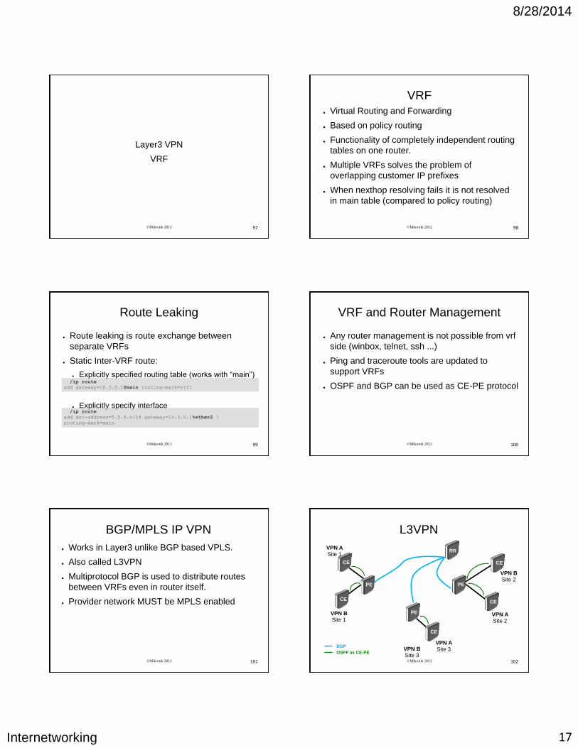
L3VPN
PE
PE PE
CE CE
CE
CE
CE
VPN A Site 3
VPN A Site 2
VPN A Site 1
VPN B Site 1
VPN B Site 2
RR
BGP
OSPF as CE-PE
8/28/2014
Internetworking 18
©Mikrotik 2012 103
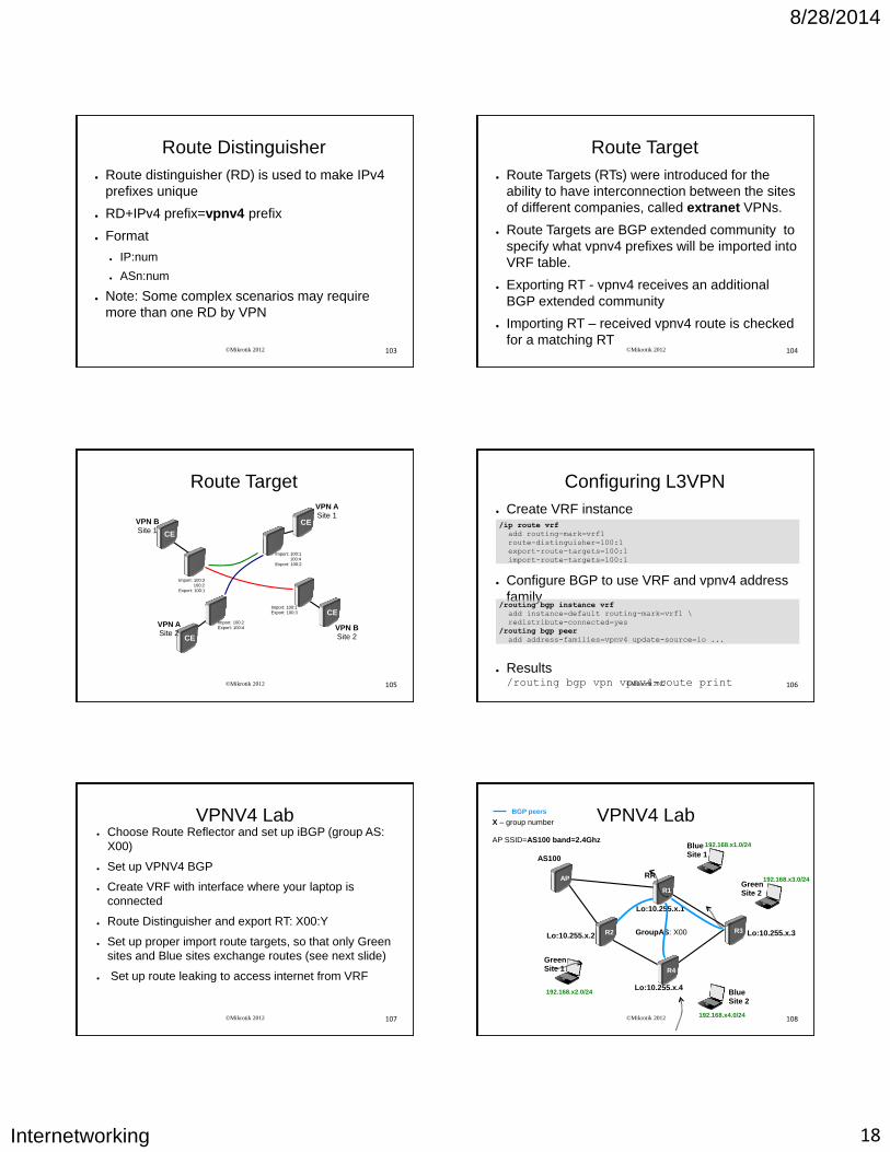
Route Distinguisher
● Route distinguisher (RD) is used to make IPv4
prefixes unique
● RD+IPv4 prefix=vpnv4 prefix
● Format
● IP:num
● ASn:num
● Note: Some complex scenarios may require
more than one RD by VPN
©Mikrotik 2012 104
Route Target
● Route Targets (RTs) were introduced for the
ability to have interconnection between the sites
of different companies, called extranet VPNs.
● Route Targets are BGP extended community to
specify what vpnv4 prefixes will be imported into
VRF table.
● Exporting RT - vpnv4 receives an additional
BGP extended community
● Importing RT – received vpnv4 route is checked
for a matching RT
©Mikrotik 2012 105
Route Target
CE
VPN A Site 1
CE
VPN A Site 2
CE
VPN B Site 1
CE
VPN B Site 2
Import: 100:2 Export: 100:4
Import: 100:1 100:4 Export: 100:2
Import: 100:1 Export: 100:3
Import: 100:3 100:2 Export: 100:1
©Mikrotik 2012 106
Configuring L3VPN
● Create VRF instance
● Configure BGP to use VRF and vpnv4 address
family
● Results /routing bgp vpn vpnv4-route print
/ip route vrf
add routing-mark=vrf1
route-distinguisher=100:1
export-route-targets=100:1
import-route-targets=100:1
/routing bgp instance vrf
add instance=default routing-mark=vrf1 \
redistribute-connected=yes
/routing bgp peer
add address-families=vpnv4 update-source=lo ...
©Mikrotik 2012 107
VPNV4 Lab ● Choose Route Reflector and set up iBGP (group AS:
X00)
● Set up VPNV4 BGP
● Create VRF with interface where your laptop is
connected
● Route Distinguisher and export RT: X00:Y
● Set up proper import route targets, so that only Green
sites and Blue sites exchange routes (see next slide)
● Set up route leaking to access internet from VRF
©Mikrotik 2012 108
VPNV4 Lab X – group number AP SSID=AS100 band=2.4Ghz
192.168.x3.0/24
R3
R4
AS100
AP
192.168.x1.0/24
R1
192.168.x2.0/24
R2
192.168.x4.0/24
Lo:10.255.x.1
Lo:10.255.x.2
Lo:10.255.x.4
Lo:10.255.x.3 GroupAS: X00
Green Site 1
Blue Site 1
Green Site 2
Blue Site 2
RR
BGP peers
8/28/2014
Internetworking 19
©Mikrotik 2012 109
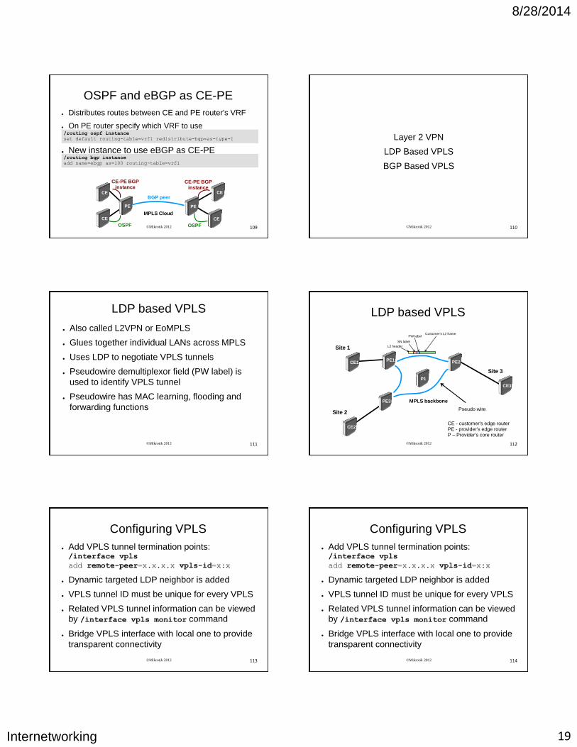
OSPF and eBGP as CE-PE
● Distributes routes between CE and PE router's VRF
● On PE router specify which VRF to use
/routing ospf instance
set default routing-table=vrf1 redistribute-bgp=as-type-1
AP
PE
MPLS Cloud
PE
CE CE
BGP peer
OSPF OSPF
CE
AP
CE
CE-PE BGP instance
CE-PE BGP instance
● New instance to use eBGP as CE-PE /routing bgp instance
add name=ebgp as=100 routing-table=vrf1
©Mikrotik 2012 110
Layer 2 VPN
LDP Based VPLS
BGP Based VPLS
©Mikrotik 2012 111
LDP based VPLS
● Also called L2VPN or EoMPLS
● Glues together individual LANs across MPLS
● Uses LDP to negotiate VPLS tunnels
● Pseudowire demultiplexor field (PW label) is
used to identify VPLS tunnel
● Pseudowire has MAC learning, flooding and
forwarding functions
©Mikrotik 2012 112
LDP based VPLS
PE1 PE2
PE3
CE1
Site 1
CE2
Site 2
CE3
Site 3
MPLS backbone
Pseudo wire
L2 header
Customer's L2 frame
SN label
PW label
CE - customer's edge router PE - provider's edge router P – Provider's core router
P1
©Mikrotik 2012 113
Configuring VPLS
● Add VPLS tunnel termination points: /interface vpls
add remote-peer=x.x.x.x vpls-id=x:x
● Dynamic targeted LDP neighbor is added
● VPLS tunnel ID must be unique for every VPLS
● Related VPLS tunnel information can be viewed by /interface vpls monitor command
● Bridge VPLS interface with local one to provide
transparent connectivity
©Mikrotik 2012 114
Configuring VPLS
● Add VPLS tunnel termination points: /interface vpls
add remote-peer=x.x.x.x vpls-id=x:x
● Dynamic targeted LDP neighbor is added
● VPLS tunnel ID must be unique for every VPLS
● Related VPLS tunnel information can be viewed by /interface vpls monitor command
● Bridge VPLS interface with local one to provide
transparent connectivity
8/28/2014
Internetworking 20
©Mikrotik 2012 115
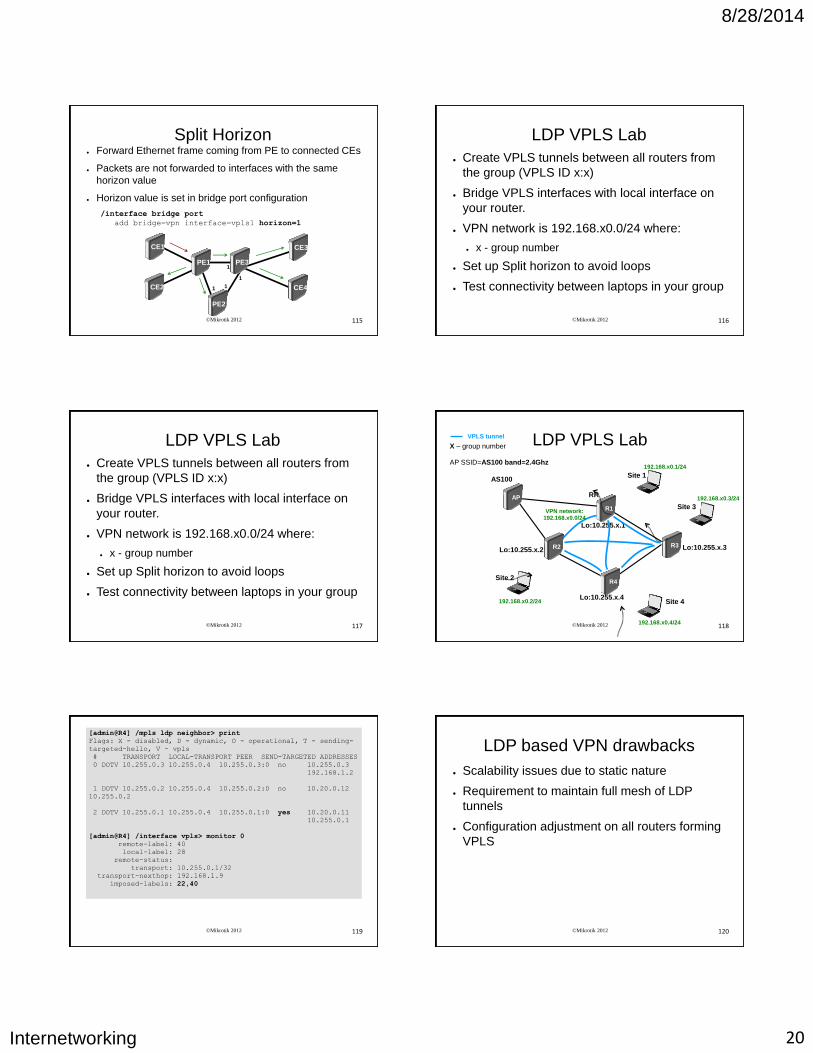
Split Horizon ● Forward Ethernet frame coming from PE to connected CEs
● Packets are not forwarded to interfaces with the same
horizon value
● Horizon value is set in bridge port configuration
/interface bridge port
add bridge=vpn interface=vpls1 horizon=1
PE1
PE2
PE3
CE1
CE2
CE3
CE4
1
1
1 1
©Mikrotik 2012 116
LDP VPLS Lab
● Create VPLS tunnels between all routers from
the group (VPLS ID x:x)
● Bridge VPLS interfaces with local interface on
your router.
● VPN network is 192.168.x0.0/24 where:
● x - group number
● Set up Split horizon to avoid loops
● Test connectivity between laptops in your group
©Mikrotik 2012 117
LDP VPLS Lab
● Create VPLS tunnels between all routers from
the group (VPLS ID x:x)
● Bridge VPLS interfaces with local interface on
your router.
● VPN network is 192.168.x0.0/24 where:
● x - group number
● Set up Split horizon to avoid loops
● Test connectivity between laptops in your group
©Mikrotik 2012 118
LDP VPLS Lab X – group number AP SSID=AS100 band=2.4Ghz
192.168.x0.3/24
R3
R4
AS100
AP
192.168.x0.1/24
R1
192.168.x0.2/24
R2
192.168.x0.4/24
Lo:10.255.x.1
Lo:10.255.x.2
Lo:10.255.x.4
Lo:10.255.x.3
Site 1
Site 4
RR
Site 3
Site 2
VPN network: 192.168.x0.0/24
VPLS tunnel
©Mikrotik 2012 119
[admin@R4] /mpls ldp neighbor> print
Flags: X - disabled, D - dynamic, O - operational, T - sending-
targeted-hello, V - vpls
# TRANSPORT LOCAL-TRANSPORT PEER SEND-TARGETED ADDRESSES
0 DOTV 10.255.0.3 10.255.0.4 10.255.0.3:0 no 10.255.0.3
192.168.1.2
1 DOTV 10.255.0.2 10.255.0.4 10.255.0.2:0 no 10.20.0.12
10.255.0.2
2 DOTV 10.255.0.1 10.255.0.4 10.255.0.1:0 yes 10.20.0.11
10.255.0.1
[admin@R4] /interface vpls> monitor 0
remote-label: 40
local-label: 28
remote-status:
transport: 10.255.0.1/32
transport-nexthop: 192.168.1.9
imposed-labels: 22,40
©Mikrotik 2012 120
LDP based VPN drawbacks
● Scalability issues due to static nature
● Requirement to maintain full mesh of LDP
tunnels
● Configuration adjustment on all routers forming
VPLS
8/28/2014
Internetworking 21
©Mikrotik 2012 121
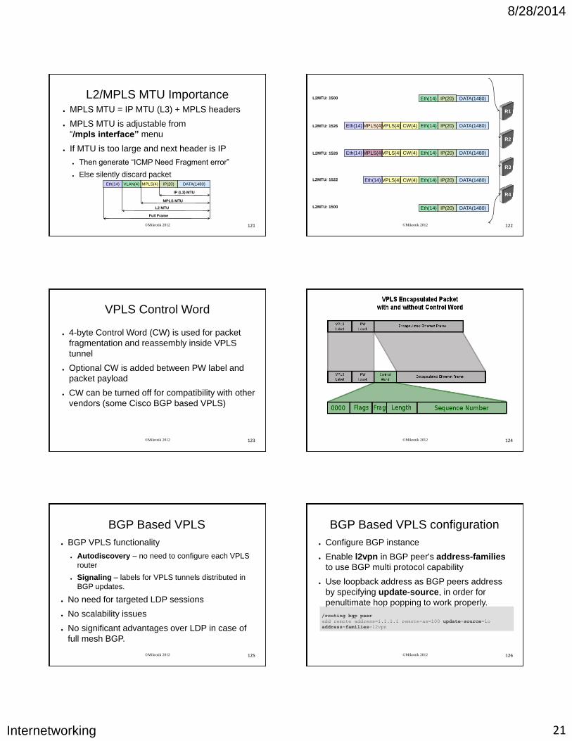
L2/MPLS MTU Importance ● MPLS MTU = IP MTU (L3) + MPLS headers
● MPLS MTU is adjustable from
“/mpls interface” menu
● If MTU is too large and next header is IP
● Then generate “ICMP Need Fragment error”
● Else silently discard packet
DATA(1480) IP(20) MPLS(4) VLAN(4) Eth(14)
IP (L3) MTU
MPLS MTU
L2 MTU
Full Frame
©Mikrotik 2012 122
DATA(1480) IP(20) Eth(14)
DATA(1480) IP(20) Eth(14) CW(4) VPLS(4) MPLS(4) Eth(14)
DATA(1480) IP(20) Eth(14) CW(4) VPLS(4) MPLS(4) Eth(14)
DATA(1480) IP(20) Eth(14) CW(4) VPLS(4) Eth(14)
DATA(1480) IP(20) Eth(14)
R1
R2
R3
R4
L2MTU: 1526
L2MTU: 1500
L2MTU: 1526
L2MTU: 1522
L2MTU: 1500
©Mikrotik 2012 123
VPLS Control Word
● 4-byte Control Word (CW) is used for packet
fragmentation and reassembly inside VPLS
tunnel
● Optional CW is added between PW label and
packet payload
● CW can be turned off for compatibility with other
vendors (some Cisco BGP based VPLS)
©Mikrotik 2012 124
©Mikrotik 2012 125
BGP Based VPLS
● BGP VPLS functionality
● Autodiscovery – no need to configure each VPLS
router
● Signaling – labels for VPLS tunnels distributed in
BGP updates.
● No need for targeted LDP sessions
● No scalability issues
● No significant advantages over LDP in case of
full mesh BGP.
©Mikrotik 2012 126
BGP Based VPLS configuration
● Configure BGP instance
● Enable l2vpn in BGP peer's address-families
to use BGP multi protocol capability
● Use loopback address as BGP peers address
by specifying update-source, in order for
penultimate hop popping to work properly.
/routing bgp peer
add remote address=1.1.1.1 remote-as=100 update-source=lo
address-families=l2vpn
8/28/2014
Internetworking 22
©Mikrotik 2012 127
BGP Based VPLS configuration ● Configure VPN bridge
● Configure BGP signaled VPLS interface
● Dynamic VPLS tunnel gets created and added
to bridge ports
– route-distinguisher – value that gets attached to VPLS
NLRI to distinguish advertisements, value should be
unique for each VPLS
– site-id – unique setting among members of particular
VPLS
/interface vpls bgp-vpls
add bridge=<bridge> bridge-horizon=1 site-id=1 \
route-distinguisher=1:1 import-route-targer=1:1 \
export-route-target=1:1
©Mikrotik 2012 128
BGP based VPLS Lab
● Choose which one of routers will be Route
reflector (for example R1)
● Set BGP peering only between RR
● Replace all statically created VPLS with BGP
VPLS
● Set import/export route targets the same as
route distinguisher.
©Mikrotik 2012 129
Traffic Engineering
©Mikrotik 2012 130
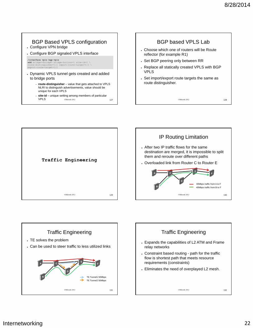
IP Routing Limitation
● After two IP traffic flows for the same
destination are merged, it is impossible to split
them and reroute over different paths
● Overloaded link from Router C to Router E
A
B
C
D
E F
40Mbps traffic from A to F
40Mbps traffic from B to F
©Mikrotik 2012 131
Traffic Engineering
● TE solves the problem
● Can be used to steer traffic to less utilized links
A
B
C
D
E F
TE Tunnel1 50Mbps
TE Tunnel2 50Mbps
©Mikrotik 2012 132
Traffic Engineering
● Expands the capabilities of L2 ATM and Frame
relay networks
● Constraint based routing - path for the traffic
flow is shortest path that meets resource
requirements (constraints)
● Eliminates the need of overplayed L2 mesh.
8/28/2014
Internetworking 23
©Mikrotik 2012 133
How it works
● TE establishes/maintains the tunnel using
RSVP (Resource Reservation Protocol)
● Tunnel path at any point is determined based
on network resources and tunnel requirements
● Available resources are flooded via OSPF
● Tunnel paths are calculated at the tunnel head
based on a fit between required and available
resources (constraint-based routing)
● RSVP TE tunnels are unidirectional ©Mikrotik 2012 134
TE Tunnel Path Options
● Tunnel path is routed based on routing table Tunnel path: use-cspf=no and empty hops
● Statically configured explicit path Tunnel path: use-cspf=no hops=<explicit hop config>
● Constrained Shortest Path First (CSPF) – head
end router calculates path to tail end using
knowledge of network state. Needs assistance
form IGP. Tunnel path: use-cspf=yes, empty hops or explicitly
configured hops
©Mikrotik 2012 135
How it works ● Tunnel head end appears as interface
● Auto TE works within the range of one area
● Traffic can be forwarded automatically to TE if
● Remote endpoint of pseudowire is the same as TE
endpoint
● BGP nexthop is tunnel endpoint ( can be turned off
by setting “use-te-nexthop=no”)
©Mikrotik 2012 136
TE configuration
● Set OSPF to use TE and configure TE on all
interfaces participating in TE tunnel
● Configure TE tunnel itself
/routing ospf set mpls-te-area=backbone
mpls-te-router-id=loopback
/mpls traffic-eng interface
add interface=ether1 bandwidth=50Mbps
/mpls traffic-eng tunnel-path
add use-cspf=no name=rt
/interface traffic-eng
add bandwidth=10Mbps primary-path=rt
from-address=10.255.1.2 to-address=10.255.1.3
©Mikrotik 2012 137
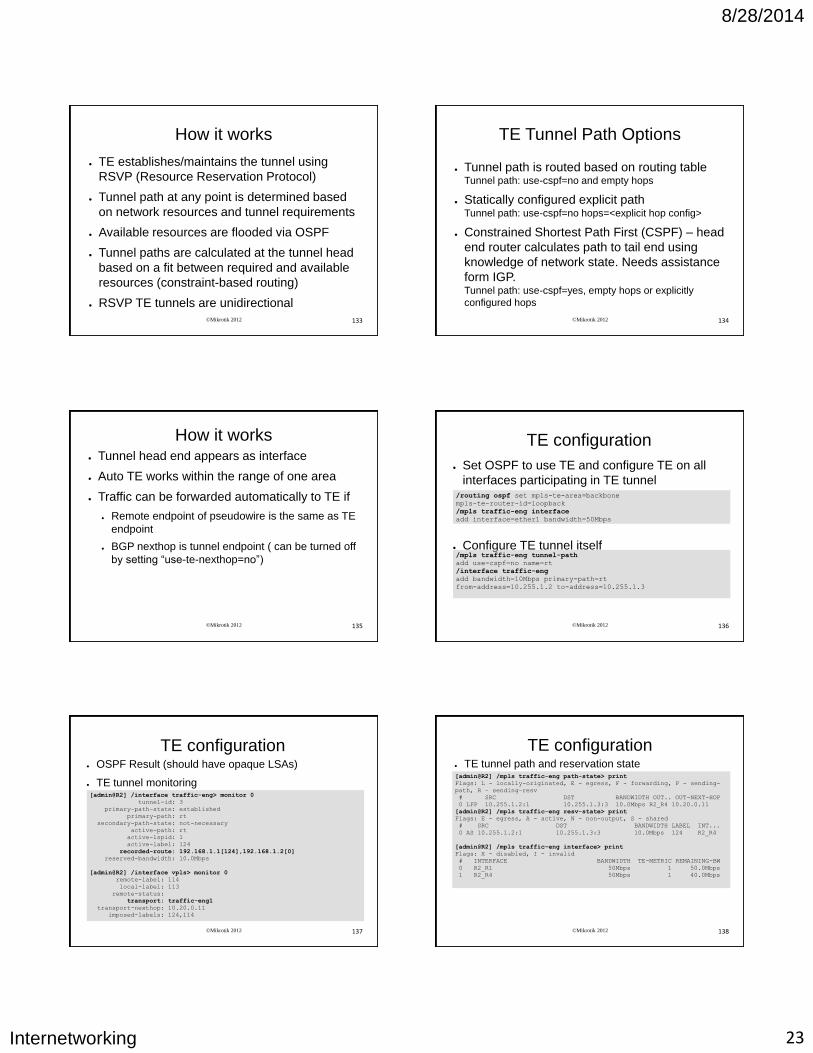
TE configuration ● OSPF Result (should have opaque LSAs)
● TE tunnel monitoring [admin@R2] /interface traffic-eng> monitor 0
tunnel-id: 3
primary-path-state: established
primary-path: rt
secondary-path-state: not-necessary
active-path: rt
active-lspid: 1
active-label: 124
recorded-route: 192.168.1.1[124],192.168.1.2[0]
reserved-bandwidth: 10.0Mbps
[admin@R2] /interface vpls> monitor 0
remote-label: 114
local-label: 113
remote-status:
transport: traffic-eng1
transport-nexthop: 10.20.0.11
imposed-labels: 124,114
©Mikrotik 2012 138
TE configuration ● TE tunnel path and reservation state [admin@R2] /mpls traffic-eng path-state> print
Flags: L - locally-originated, E - egress, F - forwarding, P - sending-
path, R - sending-resv
# SRC DST BANDWIDTH OUT.. OUT-NEXT-HOP
0 LFP 10.255.1.2:1 10.255.1.3:3 10.0Mbps R2_R4 10.20.0.11
[admin@R2] /mpls traffic-eng resv-state> print
Flags: E - egress, A - active, N - non-output, S - shared
# SRC DST BANDWIDTH LABEL INT...
0 AS 10.255.1.2:1 10.255.1.3:3 10.0Mbps 124 R2_R4
[admin@R2] /mpls traffic-eng interface> print
Flags: X - disabled, I - invalid
# INTERFACE BANDWIDTH TE-METRIC REMAINING-BW
0 R2_R1 50Mbps 1 50.0Mbps
1 R2_R4 50Mbps 1 40.0Mbps
8/28/2014
Internetworking 24
©Mikrotik 2012 139
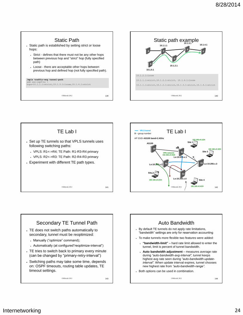
Static Path ● Static path is established by setting strict or loose
hops:
● Strict - defines that there must not be any other hops
between previous hop and "strict" hop (fully specified
path)
● Loose - there are acceptable other hops between
previous hop and defined hop (not fully specified path).
/mpls traffic-eng tunnel-path
add use-cspf=no \
hops=10.1.1.1:strict,10.1.3.1:loose,10.1.4.1:strict
©Mikrotik 2012 140
Static path example
A
B
C
D
E F
10.1.1.1
10.1.2.1
10.1.3.1 10.1.4.1
10.1.0.1
10.1.2.1:loose
10.1.1.1:strict,10.1.2.1:strict, 10.1.4.1:loose
10.1.1.1:strict,10.1.2.1:strict,10.1.3.1:strict,10.1.4.1:strict
©Mikrotik 2012 141
TE Lab I
● Set up TE tunnels so that VPLS tunnels uses
following switching paths:
● VPLS: R1<->R4; TE Path: R1-R3-R4 primary
● VPLS: R2<->R3: TE Path: R2-R4-R3 primary
● Experiment with different TE path types.
©Mikrotik 2012 142
TE Lab I X – group number AP SSID=AS100 band=2.4Ghz
192.168.x0.3/24
R3
R4
AS100
AP
192.168.x0.1/24
R1
192.168.x0.2/24
R2
192.168.x0.4/24
Lo:10.255.x.1
Lo:10.255.x.2
Lo:10.255.x.4
Lo:10.255.x.3
Site 1
Site 4
RR
Site 3
Site 2
VPN network: 192.168.x0.0/24
VPLS tunnel
©Mikrotik 2012 143
Secondary TE Tunnel Path
● TE does not switch paths automatically to
secondary, tunnel must be reoptimized:
● Manually (“optimize” command);
● Automatically (at configured“reoptimize-interval”)
● TE tries to switch back to primary every minute
(can be changed by “primary-retry-interval”)
● Switching paths may take some time, depends
on: OSPF timeouts, routing table updates, TE
timeout settings.
©Mikrotik 2012 144
Auto Bandwidth ● By default TE tunnels do not apply rate limitations,
“bandwidth” settings are only for reservation accounting
● To make tunnels more flexible two features were added:
● “bandwidth-limit” – hard rate limit allowed to enter the
tunnel, limit is percent of tunnel bandwidth.
● Auto bandwidth adjustment – measures average rate
during “auto-bandwidth-avg-interval”, tunnel keeps
highest avg rate seen during “auto-bandwidth-update-
interval”. When update interval expires, tunnel chooses
new highest rate from “auto-bandwidth-range”.
● Both options can be used in combination.
8/28/2014
Internetworking 25
©Mikrotik 2012 145
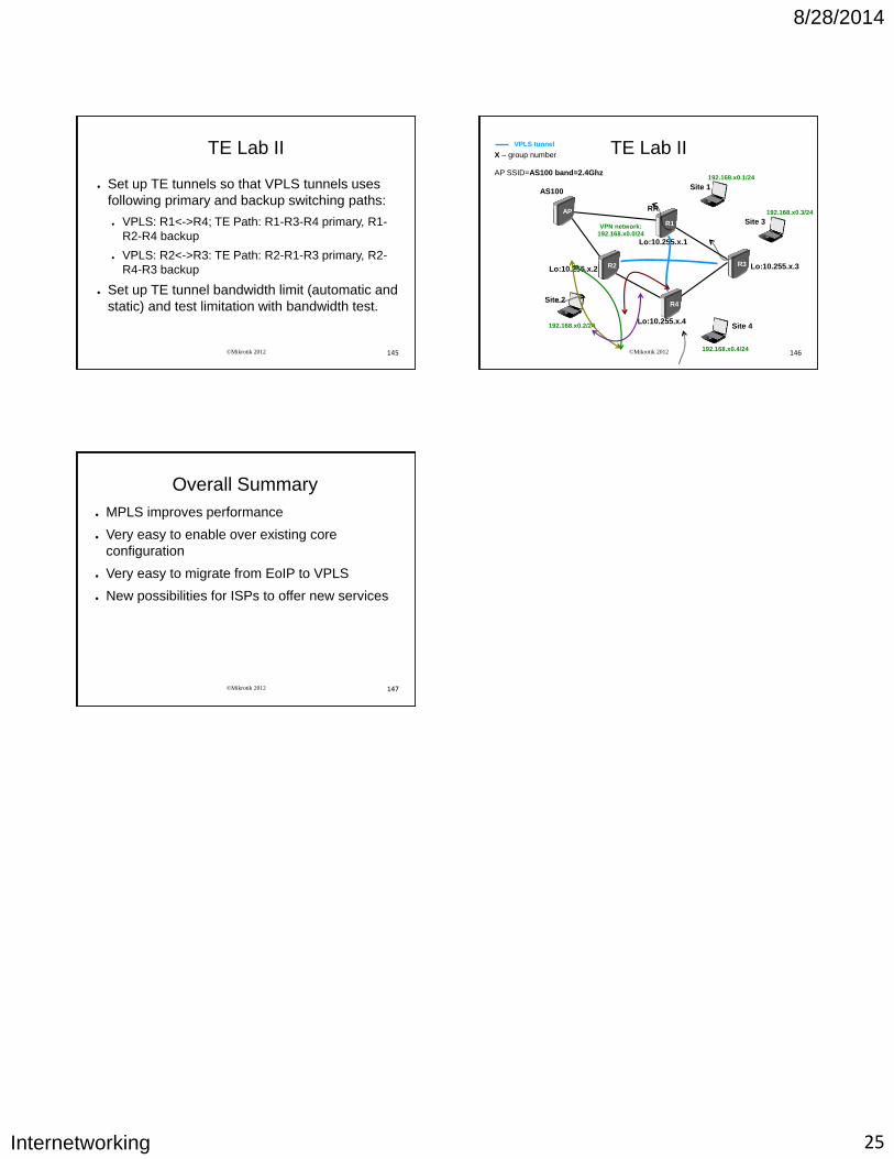
TE Lab II
● Set up TE tunnels so that VPLS tunnels uses
following primary and backup switching paths:
● VPLS: R1<->R4; TE Path: R1-R3-R4 primary, R1-
R2-R4 backup
● VPLS: R2<->R3: TE Path: R2-R1-R3 primary, R2-
R4-R3 backup
● Set up TE tunnel bandwidth limit (automatic and
static) and test limitation with bandwidth test.
©Mikrotik 2012 146
TE Lab II X – group number AP SSID=AS100 band=2.4Ghz
192.168.x0.3/24
R3
R4
AS100
AP
192.168.x0.1/24
R1
192.168.x0.2/24
R2
192.168.x0.4/24
Lo:10.255.x.1
Lo:10.255.x.2
Lo:10.255.x.4
Lo:10.255.x.3
Site 1
Site 4
RR
Site 3
Site 2
VPN network: 192.168.x0.0/24
VPLS tunnel
©Mikrotik 2012 147
Overall Summary
● MPLS improves performance
● Very easy to enable over existing core
configuration
● Very easy to migrate from EoIP to VPLS
● New possibilities for ISPs to offer new services