Embed Size (px)
Citation preview

MikroTik CRS3xx 系列交换机配置手册 v1.0e
YuSong 1 www.irouteros.com
前 言
此手册是针对 CRS3xx 系列交换机,且 RouterOS 系统版本为 v6.41 以上的二层交换网络相关配置介
绍,而 CRS1xx/CRS2xx 和其他 RB 设备的二层交换网络配置不在考虑范围内。此手册配置都以命令行为
主,不涉及 winbox 和 webfig的配置操作介绍,如果不太了解命令行操作请参阅《RouterOS 入门到精通》。
由于 RouterOS 功能太多,而且各个功能交叉, 《RouterOS 入门到精通》无法有效的对一些 MikroTik
产品进行讲解,因此特意将 CRS3xx 系列交换机操作配置,单独分离成一份配置手册。里面有与《RouterOS
入门到精通》交叉和独立的知识内容,至于 RouterOS 系统的基本操作和其他相关功能,还是请参阅
《RouterOS 入门到精通》,这里不做过多讲解。
版本: V1.0e PDF电子版
适用: RouterOS v6.41 以上系统,CRS3xx 系列交换机
作者: 余松
Web: www.irouteros.com
E-mail: [email protected] 如有更新,恕不通知!

MikroTik CRS3xx 系列交换机配置手册 v1.0e
YuSong 2 www.irouteros.com
目 录
前 言 .................................................................................................................................................................... 1
目 录 .................................................................................................................................................................... 2
第一章 CRS3xx 系列介绍 ................................................................................................................................. 3
功能 .............................................................................................................................................................. 3
CRS3xx 型号区别 .......................................................................................................................................... 4
什么是 Hardware Offloading........................................................................................................................ 4
Fast Forward ................................................................................................................................................. 8
Console 登录 ................................................................................................................................................ 9
CRS3xx 系列复位与系统重装 .................................................................................................................... 11
第二章 VLAN 配置 .......................................................................................................................................... 12
Bridge VLAN 过滤(v6.41) ........................................................................................................................... 12
VLAN 实例 1 (不同 VLAN 配置 Access 接口) ............................................................................................. 14
VLAN 实例 2 (配置 Trunk 和 Access 接口) ................................................................................................ 15
VLAN 实例 3 (配置 Trunk 和 Hybrid 接口) ................................................................................................ 16
VLAN 实例 4(配置 VLAN 三层接口) .......................................................................................................... 17
VLAN 实例 5 (配置 VLAN 三层管理 IP) ..................................................................................................... 18
CRS3xx 链路聚合 LACP(Bonding) ........................................................................................................ 19
华为 s5700 与 CRS3xx 配置 bonding ................................................................................................. 20
第三章 Switch 与 Rules (ACL) ....................................................................................................................... 21
Rules(ACL)介绍 ..................................................................................................................................... 21
镜像(Mirroring) ................................................................................................................................... 23
流量控制 (QoS) ........................................................................................................................................ 25
广播风暴控制(Traffic Storm Control) .............................................................................................. 26
基于 MAC 的 VLAN 过滤 ......................................................................................................................... 26
基于协议的 VLAN 过滤 ............................................................................................................................ 27
端口安全(Port Security) ..................................................................................................................... 28
CRS Port isolation(端口隔离) ................................................................................................................ 29
第四章 (R)STP ................................................................................................................................................. 30
STP 和 RSTP ................................................................................................................................................ 31
选举过程 .................................................................................................................................................... 33
实例 ............................................................................................................................................................ 33
第五章 其他应用和案例 .................................................................................................................................. 35
IGMP Snooping(v6.41) ................................................................................................................................ 35
DHCP Snooping 和 DHCP Option 82 .................................................................................................. 36
CRS3xx 交换路由配置案例 ........................................................................................................................ 38
交换端口配置 .................................................................................................................................... 38
管理 VLAN .......................................................................................................................................... 40
VLAN 配置 .......................................................................................................................................... 41
InterVLAN 路由策略 .......................................................................................................................... 42
启用 VLAN 过滤 ................................................................................................................................. 43
DHCP Server ........................................................................................................................................ 43
nat 与防火墙 ...................................................................................................................................... 44
参考 .................................................................................................................................................................... 45

MikroTik CRS3xx 系列交换机配置手册 v1.0e
YuSong 3 www.irouteros.com
第一章 CRS3xx 系列介绍
Cloud Router Switch(CRS)系列交换机采用高性能交换芯片,有强大的二层数据处理能力,基于
RouterOS 系统,能实现有限的三层转发和支持多种网络协议和应用。CRS3xx 全系采用了 Marvell 的芯
片,整个系列配置得到了整合和统一,操作性更强于 CRS1xx/CRS2xx 系列。Marvell 产品大家可以去了
解下,作为专业的网络芯片厂商,设计过很多交换网络产品。CRS1xx/CRS2xx 系列采用的是高通的芯片
解决方案,相较于 Marvell 缺乏完整的解决方案和可持续性。
提示:需要大家注意在配置方面 CRS3xx 系列部分参数不能应用到 CRS1xx/CRS2xx,该手册只针对
CRS3xx 系列交换机,其他 CRS 和 RB 设备可能存在不兼容。
功能
功能 描述
Forwarding(转发) 能配置端口的交换或路由功能
二层数据交换的线速转发
更大的单播 FDB 用于二层单播转发
二层转发库基于 IVL 工作
支持巨帧支持
支持 IGMP Snooping
镜像 镜像类型:
基于端口镜像
基于 VLAN 镜像
基于 MAC 镜像
VLAN 完全兼容 IEEE802.1Q 和 IEEE802.1ad
4k VLAN 缓存
多种 VLAN 配置:
基于端口 VLAN
基于协议 VLAN
基于 MAC VLAN
VLAN 过滤
VLAN 转换
Bonding 支持 802.3ad (LACP)和 balance-xor 模式硬件加速
支持 8 个成员的 bonding 接口配置
支持 30 个 bonding 接口
硬件自动故障转移和负载均衡
Quality of Service (QoS) 入向流控策略
基于端口
基于 MAC
基于 IP

MikroTik CRS3xx 系列交换机配置手册 v1.0e
YuSong 4 www.irouteros.com
基于 VLAN
基于协议
基于 DSCP
出方向端口流控
端口隔离 应用于 VLAN
ACL 入向 ACL 控制列表
基于端口分类,第二、三、四层协议包头过滤
支持过滤,转发和修改协议包头
CRS3xx 型号区别
下面的列表给出了不同型号的 CRS3xx 交换机的处理器和策略条目等参数:
型号 交换芯片 CPU 核心 SFP+ ACL 策
略数
单播
FDB 条
目
CRS326-24G-2S+ Marvell-98DX3236 800MHz 1 支持 128 16,000
CRS328-24P-4S+ Marvell-98DX3236 800MHz 1 支持 128 16,000
CRS328-4C-20S-4S+ Marvell-98DX3236 800MHz 1 支持 128 16,000
CRS305-1G-4S+ Marvell-98DX3236 800MHz 1 支持 128 16,000
CRS309-1G-8S+ Marvell-98DX8208 800MHz 2 支持 680 32 000
CRS317-1G-16S+ Marvell-98DX8216 800MHz 2 支持 680 128,000
CRS312-4C+8XG Marvell-98DX8212 650MHz 1 支持 341 32,000
CRS326-24S+2Q+ Marvell-98DX8332 650MHz 1 支持 170 32,000
CRS354-48G-4S+2Q+ Marvell-98DX3257 650MHz 1 支持 170 32,000
更多关于 CRS3xx 系列交换机的参数可以去官网查看 www.routerboard.com
什么是 Hardware Offloading
从 RouterOS v6.41 版本开始,RouterBOARD 设备的接口 master-port 二层配置操作改变,该配置
被迁移到 bridge port 菜单的 Hardware-offloading(部分内容简写为 hw-offloading),即代表硬件设备
的交换芯片为二层交换提供处理。
MikroTik CRS3xx 系列交换机配置手册 v1.0e
YuSong 5 www.irouteros.com
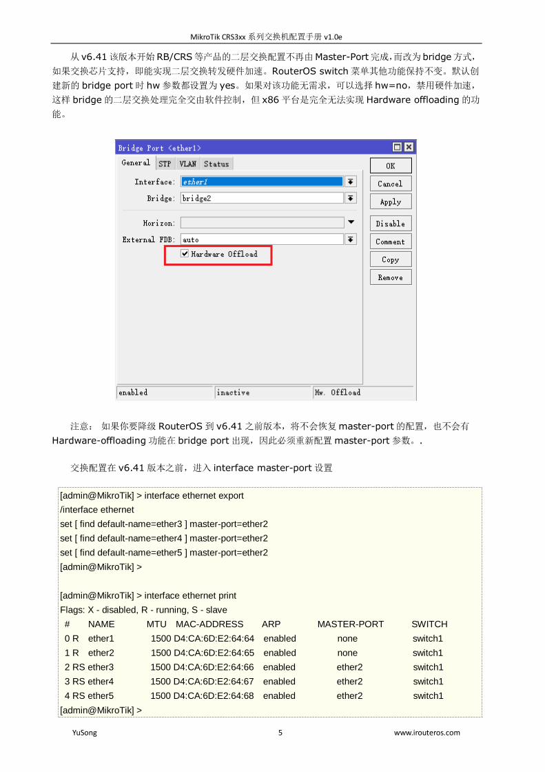
从 v6.41该版本开始RB/CRS等产品的二层交换配置不再由Master-Port完成,而改为 bridge方式,
如果交换芯片支持,即能实现二层交换转发硬件加速。RouterOS switch 菜单其他功能保持不变。默认创
建新的 bridge port 时 hw 参数都设置为 yes。如果对该功能无需求,可以选择 hw=no,禁用硬件加速,
这样 bridge 的二层交换处理完全交由软件控制,但 x86 平台是完全无法实现 Hardware offloading 的功
能。
注意: 如果你要降级 RouterOS 到 v6.41 之前版本,将不会恢复 master-port 的配置,也不会有
Hardware-offloading 功能在 bridge port 出现,因此必须重新配置 master-port 参数。.
交换配置在 v6.41 版本之前,进入 interface master-port 设置
[admin@MikroTik] > interface ethernet export
/interface ethernet
set [ find default-name=ether3 ] master-port=ether2
set [ find default-name=ether4 ] master-port=ether2
set [ find default-name=ether5 ] master-port=ether2
[admin@MikroTik] >
[admin@MikroTik] > interface ethernet print
Flags: X - disabled, R - running, S - slave
# NAME MTU MAC-ADDRESS ARP MASTER-PORT SWITCH
0 R ether1 1500 D4:CA:6D:E2:64:64 enabled none switch1
1 R ether2 1500 D4:CA:6D:E2:64:65 enabled none switch1
2 RS ether3 1500 D4:CA:6D:E2:64:66 enabled ether2 switch1
3 RS ether4 1500 D4:CA:6D:E2:64:67 enabled ether2 switch1
4 RS ether5 1500 D4:CA:6D:E2:64:68 enabled ether2 switch1
[admin@MikroTik] >

MikroTik CRS3xx 系列交换机配置手册 v1.0e
YuSong 6 www.irouteros.com
从 v6.41 版本开始,交换端口配置在 bridge port,添加接口时默认开启 hw-offload
[admin@MikroTik] > interface bridge export
/interface bridge
add name=bridge1 igmp-snooping=no protocol-mode=none
/interface bridge port
add bridge=bridge1 interface=ether2
add bridge=bridge1 interface=ether3
add bridge=bridge1 interface=ether4
add bridge=bridge1 interface=ether5
[admin@MikroTik] >
[admin@MikroTik] > interface bridge port print
Flags: X - disabled, I - inactive, D - dynamic, H - hw-offload
# INTERFACE BRIDGE HW PVID PRIORITY PATH-COST INTERNAL-PATH-COST HORIZON
0 H ether2 bridge1 yes 1 0x80 10 10 none
1 H ether3 bridge1 yes 1 0x80 10 10 none
2 H ether4 bridge1 yes 1 0x80 10 10 none
3 H ether5 bridge1 yes 1 0x80 10 10 none
[admin@MikroTik] >
在 winbox 的操作界面,可以看到 ports 菜单下,加入桥接的网卡前缀会出现 H 或 IH,H 代表
Hardware-offloading 启用硬件加速,IH 表示 inactive Hw.offload,网卡未连接,无法激活硬件加速,
而在下图的 wlan1 上没有出现 H 或 IH 代表无线网卡不支持硬件加速:
当一个端口接收到数据包,首先交给 switch logic(交换逻辑芯片),switch logic 决定包应该去哪个
端口(最常见的情况是,这个决定是基于包的目标 MAC 地址做出的,但具体情况根据包和配置可能涉及到其
他参数)。通常情况下,数据包将不会交给 RouterOS 处理(只统计数据,表明包已经通过),这是因为数据包
MikroTik CRS3xx 系列交换机配置手册 v1.0e
YuSong 7 www.irouteros.com
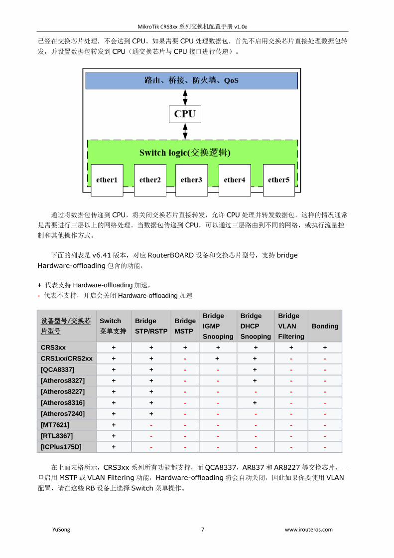
已经在交换芯片处理,不会达到 CPU。如果需要 CPU 处理数据包,首先不启用交换芯片直接处理数据包转
发,并设置数据包转发到 CPU(通交换芯片与 CPU 接口进行传递)。
通过将数据包传递到 CPU,将关闭交换芯片直接转发,允许 CPU 处理并转发数据包,这样的情况通常
是需要进行三层以上的网络处理。当数据包传递到 CPU,可以通过三层路由到不同的网络,或执行流量控
制和其他操作方式。
下面的列表是 v6.41 版本,对应 RouterBOARD 设备和交换芯片型号,支持 bridge
Hardware-offloading 包含的功能,
+ 代表支持 Hardware-offloading 加速,
- 代表不支持,开启会关闭 Hardware-offloading 加速
设备型号/交换芯
片型号
Switch
菜单支持
Bridge
STP/RSTP
Bridge
MSTP
Bridge
IGMP
Snooping
Bridge
DHCP
Snooping
Bridge
VLAN
Filtering
Bonding
CRS3xx + + + + + + +
CRS1xx/CRS2xx + + - + + - -
[QCA8337] + + - - + - -
[Atheros8327] + + - - + - -
[Atheros8227] + + - - - - -
[Atheros8316] + + - - + - -
[Atheros7240] + + - - - - -
[MT7621] + - - - - - -
[RTL8367] + - - - - - -
[ICPlus175D] + - - - - - -
在上面表格所示,CRS3xx 系列所有功能都支持,而 QCA8337,AR837 和 AR8227 等交换芯片,一
旦启用 MSTP 或 VLAN Filtering 功能,Hardware-offloading 将会自动关闭,因此如果你要使用 VLAN
配置,请在这些 RB 设备上选择 Switch 菜单操作。

MikroTik CRS3xx 系列交换机配置手册 v1.0e
YuSong 8 www.irouteros.com
警告:Hardware-offloading 只提供二层数据转发处理,不支持三层或三层以上的转发处理,当前
CRS3xx 系列交换机的三层以上数据都是交给 CPU,会导致 CPU 负载增加,配置三层网络时请谨慎操作,
并避免意外发生。
Fast Forward
Fast Forward 在指定的条件下可以快速转发数据包,当 Fast Forward 功能被启用,这时 Bridge 能
快速处理数据包转发,会跳过 Bridge 下多个关联端口查询,包括 MAC 学习。
下面是启用 Fast Forward 相关的条件清单:
Bridge 设置 fast-forward= yes
Bridge 中只有 2 个运行端口
Bridge 中的 2 个端口,支持 Fast Path ,并启用 Fast Path 功能。
Bridge Hardware Offloading 关闭
protocol-mode 设置为 none
Bridge VLAN Filtering 功能关闭
unknown-multicast-flood 设置为 yes
unknown-unicast-flood 设置为 yes
broadcast-flood 设置为 yes
horizon 参数在两个端口配置为 none
FastForward 的设计概念是禁止 MAC 学习,这实现更快的包转发。MAC 学习可以防止流量发送到多
个接口,但是当一个包只能通过一个接口发送时,就不需要 MAC 学习了

MikroTik CRS3xx 系列交换机配置手册 v1.0e
YuSong 9 www.irouteros.com
启用 hardware offloading 时 Fast Forward 会禁用。hardware offloading 可以实现线速转发,即
使用内置的交换芯片处理
Fast Forward 使用 CPU 转发数据,RouterOS 调用硬件转发处理上看会有这样的结果:
Hardware offloading > Fast Forward > Fast Path > Slow Path
通下面的命令可以查看 Fast Forward 启用状态下,处理了多少数据:
[admin@MikroTik] > /interface bridge settings print
use-ip-firewall: no
use-ip-firewall-for-vlan: no
use-ip-firewall-for-pppoe: no
allow-fast-path: yes
bridge-fast-path-active: yes
bridge-fast-path-packets: 0
bridge-fast-path-bytes: 0
bridge-fast-forward-packets: 1279812
bridge-fast-forward-bytes: 655263744
注意:如果数据被 Fast Path 处理,这时 Fast Forward 不会被激活。数据包统计可以用来衡量 Fast
Forward 是否被激活。
从 RouterOS 6.44beta28 可以查看 Fast Forward 状态,如下:
[admin@MikroTik] > /interface bridge monitor bridge1
state: enabled
current-mac-address: D4:CA:6D:E1:B5:82
root-bridge: yes
root-bridge-id: 0x8000.00:00:00:00:00:00
root-path-cost: 0
root-port: none
port-count: 2
designated-port-count: 0
fast-forward: yes
警告:禁用或启用 fast-forward 将临时禁用所有桥接端口,以便设置生效。每当在实际生产环境中更改
此属性时,都必须考虑到这一点,这样会导致桥接网络被临时中断。
Console 登录
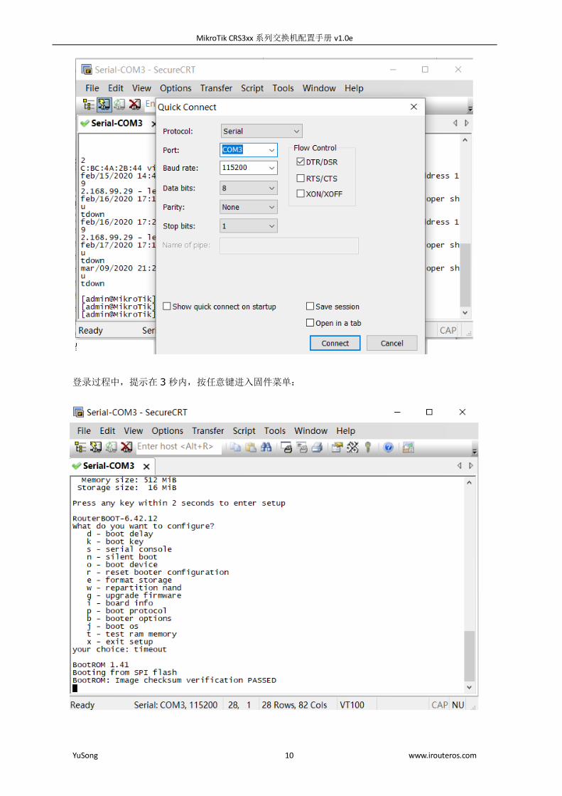
在不使用 winbox 登录情况下,配置 CRS3xx 系列交换机,提供了一个 RJ45 的 console 接口,这里
通 SecureCRT 软件选择 Serial 协议,默认波特率为 115200,需要开启 DTR/DSR
MikroTik CRS3xx 系列交换机配置手册 v1.0e
YuSong 10 www.irouteros.com
登录过程中,提示在 3 秒内,按任意键进入固件菜单:

MikroTik CRS3xx 系列交换机配置手册 v1.0e
YuSong 11 www.irouteros.com
RouterOS 系统默认账号是 admin,密码为空,对于 Winbox 登录基于 RouterOS 系统的 CRS3xx
系列交换机,这里不做过多的介绍,请参考《RouterOS 入门到精通》
CRS3xx 系列复位与系统重装
基于 RouterOS 系统的 CRS,复位和系统重装和其他 MikroTik 硬件设备一样,这里主要介绍 reset
按钮的操作
reset 硬件复位按钮功能:
载入备份 RouterBOOT 固件
启动后,按住 reset 复位键,在通电 3 秒后,会重新载入备 Boot 固件。这种情况通常在固件升级失败
后,重新启动载入备份固件。(按住 3 秒)
复位 RouterOS 配置
通电后,如果你持续按住复位键,直到 LED 灯闪烁,放开复位键后,RouterOS 配置将会复位( 按住 5
秒)
启用 CAPs 模式
让该设备连接到网络中的 CAPsMAN,持续按住复位键大于 5 秒,LED 灯会常亮,放开后会转入 CAPs
模式 (按住 10 秒)
启动 RouterBOARD Netinstall 模式(网络安装)
通电后持续按住复位键,直到 LED 灯常亮关闭,放开复位键,此时 RouterBOARD 会寻找网络中的
Netinstall 服务。你同样可以根据 windows 中的 Netinstall 程序查找到,并显示 RouterBOARD 信息再
放开复位键。(按住 15 秒)

MikroTik CRS3xx 系列交换机配置手册 v1.0e
YuSong 12 www.irouteros.com
其他硬件的复位操作,参考《RouterOS 入门到精通》3.5 章节
系统复位和备份:参考《RouterOS 入门到精通》2.2 章节
netinstall 系统重装:参考《RouterOS 入门到精通》1.1 章节
第二章 VLAN 配置
Bridge VLAN 过滤(v6.41)
目前只有CRS3xx系列设备能够同时使用Bridge VLAN filtering下所有功能和hardware offloading,
其他设备在启用桥接 VLAN 过滤时不能完全使用内置交换芯片。
RouterOS 从 v6.41rc 版本开始,Bridge 提供对 VLAN 的二层转发和 VLAN 标记修改等功能,这样的
设置让 Bridge 功能更像一台以太网交换机,并且克服了生成树协议的兼容问题。RouterOS v6.41rc 的
VLAN 过滤功能已经能支持 STP (802.1D), RSTP (802.1w)和 MSTP (802.1s)
操作路径: /interface bridge
创建 Bridge 时,可以选择 VLAN 的设置, vlan-filtering 是用于桥接下全局的 VLAN 识别和 VLAN
tags 标记处理。如果 vlan-filtering=no, Bridge 将忽略 VLAN tag 标记。只能工作在
shared-VLAN-learning (SVL) 模式,也不能修改 VLAN 数据包的 tags。设置为 yes,相关的 VLAN 功
能和 independent-VLAN-learning (IVL) 模式将启用。当 Bridge 加入端口,实现二层转发,bridge 自
身也将会成为一个接口,并拥有自己的 PVID(Port VLAN ID)。
属性 描述
vlan-filtering (yes | no; 默认:no) 启用和禁用 bridge 下的 VLAN 功能
pvid (1..4094; 默认:1) 指定 Bridge 接口下的 Port VLAN ID (pvid) ,用于分配 VLAN
无标记入口
在 winbox 中创建一个 bridge1,可以在 vlan 菜单下找到 vlan-filtering 选项

MikroTik CRS3xx 系列交换机配置手册 v1.0e
YuSong 13 www.irouteros.com
在 6.41 版本后,设置 Bridge port 下新增了相关 vlan 过滤参数:
属性 描述
frame-types (admit-all |
admit-only-untagged-and-priority-tagged |
admit-only-vlan-tagged; 默认:admit-all)
指定一个 Bridge 端口准许进入的针类型
ingress-filtering (yes | no; 默认:no) 启用或禁用过滤查找一个入口在 Bridge VLAN 表中的匹配
pvid (1..4094; 默认:1) 指定 Bridge 接口下的 Port VLAN ID (pvid) ,用于分配 VLAN
无标记入口
操作路径: /interface bridge vlan
Bridge 的 VLAN 表是对每个 VLAN 端口的映射关系做出方向的 VLAN 标记处理。Trunk(tagged)
接口标记学习到的 VLAN ID 发送出去,而 access(untagged)接口则在发送前删除 VLAN ID 标记
属性 描述
bridge (名称) VLAN 配置属于那个一个 Bridge 接口下
disabled (yes | no; 默认:no) 启用或禁用 Bridge VLAN
tagged (接口; 默认:none) 设置 Trunk 的接口列表,用于选择 VLAN 标记(tagged)出
方向的操作,配置可以多接口例如:
tagged=ether1,ether2 .
untagged (interfaces; Default:none) 设置 access 的接口列表,用于选择删除出方向的 VLAN 标
记(untagged),配置可以多接口例
如: tagged=ether3,ether4 .
vlan-ids (1..4094) VLAN ID 列表,设置确定的 VLAN ID 范围或通过逗号隔离相

MikroTik CRS3xx 系列交换机配置手册 v1.0e
YuSong 14 www.irouteros.com
互独立的 VLAN,例如:
vlan-ids=100-115,120,122,128-130 .
VLAN -ids 参数可用于指定 VLAN 的集合或范围,但在单个 Bridge VLAN 表条目中指定多个 VLAN 应
该仅用于 trunk 端口。如果为 access 端口指定了多个 vlan,那么不管 PVID 值如何,标记的包可能作为
未标记包通过错误的 access 端口发送出去。
操作路径: /interface bridge host
Bridge host 是主机列表,可以监测学习到的 MAC 地址,当 vlan-filtering 启用,会显示学习到的
VLAN ID
[admin@MikroTik] > interface bridge host print where !local
Flags: L - local, E - external-fdb
BRIDGE VID MAC-ADDRESS ON-INTERFACE AGE
bridge1 200 D4:CA:6D:77:2E:F0 ether3 7s
bridge1 200 E4:8D:8C:1B:05:F0 ether2 2s
bridge1 300 D4:CA:6D:74:65:9D ether4 3s
bridge1 300 E4:8D:8C:1B:05:F0 ether2 2s
bridge1 400 4C:5E:0C:4B:89:5C ether5 0s
bridge1 400 E4:8D:8C:1B:05:F0 ether2 0s
[admin@MikroTik] >
注意:在使用 Bridge VLAN Filtering 时,请确保将所有需要的二层端口添加到 Bridge Port 表中,
如果某些 VLAN 需要开启三层路由功能,需要从这些 VLAN 端口设置允许访问 CPU,操作可以参考管理端
口部分
VLAN 实例 1 (不同 VLAN 配置 Access 接口)
这个实例介绍没有 trunk 端口的情况下,常见二层不同 VLAN 的 access 接口配置,

MikroTik CRS3xx 系列交换机配置手册 v1.0e
YuSong 15 www.irouteros.com
创建一个 bridge 接口,并禁用 vlan-filtering ,在配置完成 VLAN 之前,避免丢失路由器的管理
/interface bridge
add name=bridge1 vlan-filtering=no
添加 bridge ports 的接口成员,并指定每个 access 接口的 PVID。
/interface bridge port
add bridge=bridge1 interface=ether2
add bridge=bridge1 interface=ether6 pvid=300
add bridge=bridge1 interface=ether7 pvid=300
add bridge=bridge1 interface=ether8 pvid=400
add bridge=bridge1 interface=ether9 pvid=400
以上配置完成后,RouterOS 会在 bridge vlan 下自动生成端口和 vlan id 对应关系
最后,当 VLAN 配置完成,启用 vlan-filtering
/interface bridge set bridge1 vlan-filtering=yes
VLAN 实例 2 (配置 Trunk 和 Access 接口)
这个实例介绍常见二层 VLAN 的 trunk 和 access 接口配置
创建一个 bridge 接口,并禁用 vlan-filtering ,在配置完成 VLAN 之前,避免丢失路由器的管理
/interface bridge
add name=bridge1 vlan-filtering=no

MikroTik CRS3xx 系列交换机配置手册 v1.0e
YuSong 16 www.irouteros.com
添加 bridge ports 的接口成员,并指定每个 access 接口的 PVID,trunk 接口不用指定。
/interface bridge port
add bridge=bridge1 interface=ether2
add bridge=bridge1 interface=ether6 pvid=200
add bridge=bridge1 interface=ether7 pvid=300
add bridge=bridge1 interface=ether8 pvid=400
添加 bridge VLAN,并指定 tagged 和 untagged 接口
/interface bridge vlan
add bridge=bridge1 tagged=ether2 untagged=ether6 vlan-ids=200
add bridge=bridge1 tagged=ether2 untagged=ether7 vlan-ids=300
add bridge=bridge1 tagged=ether2 untagged=ether8 vlan-ids=400
最后,当 VLAN 配置完成,启用 vlan-filtering
/interface bridge set bridge1 vlan-filtering=yes
VLAN 实例 3 (配置 Trunk 和 Hybrid 接口)
该实例介绍二层 VLAN 混杂模式的配置
创建一个 bridge 接口,并禁用 vlan-filtering ,在配置完成 VLAN 之前,避免丢失路由器的管理
/interface bridge
add name=bridge1 vlan-filtering=no

MikroTik CRS3xx 系列交换机配置手册 v1.0e
YuSong 17 www.irouteros.com
添加 bridge ports 的接口成员,并指定每个 access 接口的 PVID,trunk 接口不用指定。
/interface bridge port
add bridge=bridge1 interface=ether2
add bridge=bridge1 interface=ether6 pvid=200
add bridge=bridge1 interface=ether7 pvid=300
add bridge=bridge1 interface=ether8 pvid=400
添加 Bridge VLAN,并指定 tagged and untagged 端口,设置 ether6.ether7 和 ether8 为 Hybrid
端口
/interface bridge vlan
add bridge=bridge1 tagged=ether2,ether7,ether8 untagged=ether6 vlan-ids=200
add bridge=bridge1 tagged=ether2,ether6,ether8 untagged=ether7 vlan-ids=300
add bridge=bridge1 tagged=ether2,ether6,ether7 untagged=ether8 vlan-ids=400
最后,当 VLAN 配置完成,启用 vlan-filtering
/interface bridge set bridge1 vlan-filtering=yes
VLAN 实例 4(配置 VLAN 三层接口)
该实例介绍,如何二层 VLAN 上创建三层接口
创建一个 bridge 接口,并禁用 vlan-filtering ,在配置完成 VLAN 之前,避免丢失路由器的管理
/interface bridge
add name=bridge1 vlan-filtering=no
MikroTik CRS3xx 系列交换机配置手册 v1.0e
YuSong 18 www.irouteros.com
添加 bridge ports 的接口成员,并指定每个 access 接口的 PVID,trunk 接口不用指定。
/interface bridge port
add bridge=bridge1 interface=ether6 pvid=200
add bridge=bridge1 interface=ether7 pvid=300
add bridge=bridge1 interface=ether8 pvid=400
添加 bridge VLAN,并指定 tagged 和 untagged 接口,在这个实例中设置 tagged 为 bridge1,即
将 VLAN trunk 到路由器内部
/interface bridge vlan
add bridge=bridge1 tagged=bridge1 untagged=ether6 vlan-ids=200
add bridge=bridge1 tagged=bridge1 untagged=ether7 vlan-ids=300
add bridge=bridge1 tagged=bridge1 untagged=ether8 vlan-ids=400
进入/interface vlan 菜单,创建 bridge1 接口下对应的 vlan id,允许处理来之二层的 vlan 数据
/interface vlan
add interface=bridge1 name=vlan200 vlan-id=200
add interface=bridge1 name=vlan300 vlan-id=300
add interface=bridge1 name=vlan400 vlan-id=400
在/ip address 菜单下添加对应 VLAN 的 IP 地址
/ip address
add address=20.0.0.1/24 interface=vlan200 network=20.0.0.0
add address=30.0.0.1/24 interface=vlan300 network=30.0.0.0
add address=40.0.0.1/24 interface=vlan400 network=40.0.0.0
最后,当 VLAN 配置完成,启用 vlan-filtering
/interface bridge set bridge1 vlan-filtering=yes
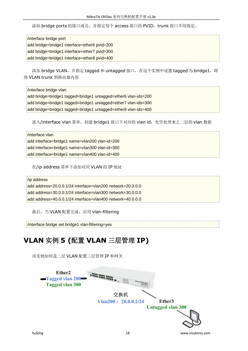
VLAN 实例 5 (配置 VLAN 三层管理 IP)
该实例如何是二层 VLAN 配置三层管理 IP 和网关

MikroTik CRS3xx 系列交换机配置手册 v1.0e
YuSong 19 www.irouteros.com
创建一个 bridge 接口,并禁用 vlan-filtering ,在配置完成 VLAN 之前,避免丢失路由器的管理
/interface bridge
add name=bridge1 vlan-filtering=no
添加 bridge ports 的接口成员,并指定每个 access 接口的 PVID,trunk 接口不用指定。
/interface bridge port
add bridge=bridge1 interface=ether2
add bridge=bridge1 interface=ether3 pvid=300
添加 bridge VLAN,并指定 tagged 和 untagged 接口,在这个实例中设置 tagged 为 bridge1,即
将 VLAN trunk 到路由器内部
/interface bridge vlan
add bridge=bridge1 tagged=ether2,bridge1 vlan-ids=200
add bridge=bridge1 tagged=ether2 untagged=ether3 vlan-ids=300
进入/interface vlan 菜单,创建 bridge1 接口下对应的 vlan id,允许处理来之二层的 vlan 数据
/interface vlan
add interface=bridge1 name=vlan200 vlan-id=200
在/ip address 菜单下添加对应 VLAN 的 IP 地址
/ip address
add address=20.0.0.2/24 interface=vlan200
在/ip route 菜单下添加对应网关
/ip route
add gateway=20.0.0.1
最后,当 VLAN 配置完成,启用 vlan-filtering
/interface bridge set bridge1 vlan-filtering=yes
注意:如果你仅仅是通过二层协议(如 MAC-telnet)连接 CRS 设备,那可以跳过添加 IP 地址的步骤,
仅把 VLAN 传递给 CPU。
CRS3xx 链路聚合 LACP(Bonding)
LACP 在 RouterOS 被定义到 Bonding 配置下,从 RouterOS v6.42 开始,所有的 CRS3xx 系列的
支持 Bonding 接口的硬件加速,但仅支持 802.3ad 和 balance-xor 两种模式,其他 Bonding 模式只能
使用 CPU 处理。

MikroTik CRS3xx 系列交换机配置手册 v1.0e
YuSong 20 www.irouteros.com
下面事例创建一个硬件加速的 bonding接口,当802.3ad模式选择,将支持 LACP (Link Aggregation
Control Protocol),ether1 和 ether2 还未加入到 Bridge 中。
/interface bonding
add mode=802.3ad name=bond1 slaves=ether1,ether2
Bonding 接口可以与其他接口一起添加到 bridge 中:
/interface bridge
add name=bridge
/interface bridge port
add bridge=bridge interface=bond1 hw=yes
add bridge=bridge interface=ether3 hw=yes
add bridge=bridge interface=ether4 hw=yes
注意:已经配置到 bridge port 下的接口,添加到 Bonding 中,RouterOS 会提示无法添加接口,即
bonding 和 bridge 的接口无法重复添加
Bonding 接口配置完成后,确保硬件加速开启,在命令行下查看是 HW 为“yes”,Winbox 下查看
bridge port 下端口前缀为“H”
/interface bridge port print
Flags: X - disabled, I - inactive, D - dynamic, H - hw-offload
# INTERFACE BRIDGE HW
0 H bond1 bridge yes
1 H ether3 bridge yes
2 H ether4 bridge yes
注意: 集成的交换芯片会使用 Layer2+Layer3+Layer4 的传输数据做为哈希算法策略,如果手动改
变该哈希策略,bonding 将失效。其他相关的 Bonding 设置可以参考《RouterOS 入门到精通》第十六章
节。
华为 s5700 与 CRS3xx 配置 bonding
华为 s5700 创建 eth-trunk1,并设置 mode 为 lacp,配置 vlan 为 200
interface Eth-Trunk1
port link-type access
port default vlan 200
mode lacp
将 s5700 的 2 和 3 口加入 eth-trunk1
interface GigabitEthernet0/0/2
eth-trunk 1
interface GigabitEthernet0/0/3
eth-trunk 1
MikroTik CRS3xx 系列交换机配置手册 v1.0e
YuSong 21 www.irouteros.com
CRS3xx 配置
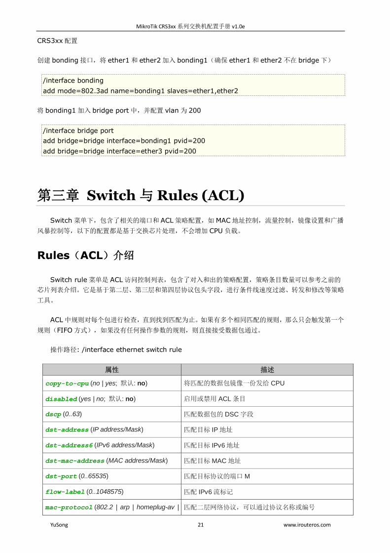
创建 bonding 接口,将 ether1 和 ether2 加入 bonding1(确保 ether1 和 ether2 不在 bridge 下)
/interface bonding
add mode=802.3ad name=bonding1 slaves=ether1,ether2
将 bonding1 加入 bridge port 中,并配置 vlan 为 200
/interface bridge port
add bridge=bridge interface=bonding1 pvid=200
add bridge=bridge interface=ether3 pvid=200
第三章 Switch 与 Rules (ACL)
Switch 菜单下,包含了相关的端口和 ACL 策略配置,如 MAC 地址控制,流量控制,镜像设置和广播
风暴控制等,以下的配置都是基于交换芯片处理,不会增加 CPU 负载。
Rules(ACL)介绍
Switch rule 菜单是 ACL 访问控制列表,包含了对入和出的策略配置,策略条目数量可以参考之前的
芯片列表介绍。它是基于第二层、第三层和第四层协议包头字段,进行条件线速度过滤、转发和修改等策略
工具。
ACL 中规则对每个包进行检查,直到找到匹配为止。如果有多个相同匹配的规则,那么只会触发第一个
规则(FIFO 方式),如果没有任何操作参数的规则,则直接接受数据包通过。
操作路径: /interface ethernet switch rule
属性 描述
copy-to-cpu (no | yes; 默认: no) 将匹配的数据包镜像一份发给 CPU
disabled (yes | no; 默认: no) 启用或禁用 ACL 条目
dscp (0..63) 匹配数据包的 DSC 字段
dst-address (IP address/Mask) 匹配目标 IP 地址
dst-address6 (IPv6 address/Mask) 匹配目标 IPv6 地址
dst-mac-address (MAC address/Mask) 匹配目标 MAC 地址
dst-port (0..65535) 匹配目标协议的端口 M
flow-label (0..1048575) 匹配 IPv6 流标记
mac-protocol (802.2 | arp | homeplug-av | 匹配二层网络协议,可以通过协议名称或编号

MikroTik CRS3xx 系列交换机配置手册 v1.0e
YuSong 22 www.irouteros.com
ip | ipv6 | ipx | lldp | loop-protect |
mpls-multicast | mpls-unicast | packing-compr
| packing-simple | pppoe | pppoe-discovery |
rarp | service-vlan | vlan | or 0..65535 | or
0x0000-0xffff)
mirror (no | yes) 镜像匹配的数据包,并发送到指定的镜像端口
new-dst-ports (ports) 通过指定修改目标端口,如果指定是空,则丢弃所有数据。
多个"new-dst-ports" 在 CRS3xx 系列不支持。
new-vlan-id (0..4095) 修改 VLAN ID。
要求 vlan-filtering=yes .
new-vlan-priority (0..7) 修改 VLAN 优先级标记,
要求 vlan-filtering=yes .
ports (ports) 匹配接收数据的交换机端口。
protocol (dccp | ddp | egp | encap | etherip |
ggp | gre | hmp | icmp | icmpv6 | idpr-cmtp |
igmp | ipencap | ipip | ipsec-ah | ipsec-esp |
ipv6 | ipv6-frag | ipv6-nonxt | ipv6-opts |
ipv6-route | iso-tp4 | l2tp | ospf | pim | pup | rdp
| rspf | rsvp | sctp | st | tcp | udp | udp-lite |
vmtp | vrrp | xns-idp | xtp | or 0..255)
匹配 IP 协议,可以通过协议名称或编号
redirect-to-cpu (no | yes) 修改匹配数据包的目标端口到 CPU
src-address (IP address/Mask) 匹配源 IP 地址
src-address6 (IPv6 address/Mask) 匹配源 IPv6 地址
src-mac-address (MAC address/Mask) 匹配源 MAC 地址
src-port (0..65535) 匹配协议源端口
switch (switch group) 策略规则应用的 switch 组
traffic-class (0..255) 匹配 IPv6 传输类别。
vlan-id (0..4095) 匹配 VLAN ID VLAN ID.
要求 vlan-filtering=yes .
vlan-header (not-present | present) 匹配 VLAN 头,VLAN 头存在或不存在。
要求 vlan-filtering=yes .
vlan-priority (0..7) 匹配 VLAN 优先级。
在 Rule 策略下,分为执行和条件操作两部分,即 ACL 采用的是 if-then 方式,如果满足什么条件,这
时执行上面操作。
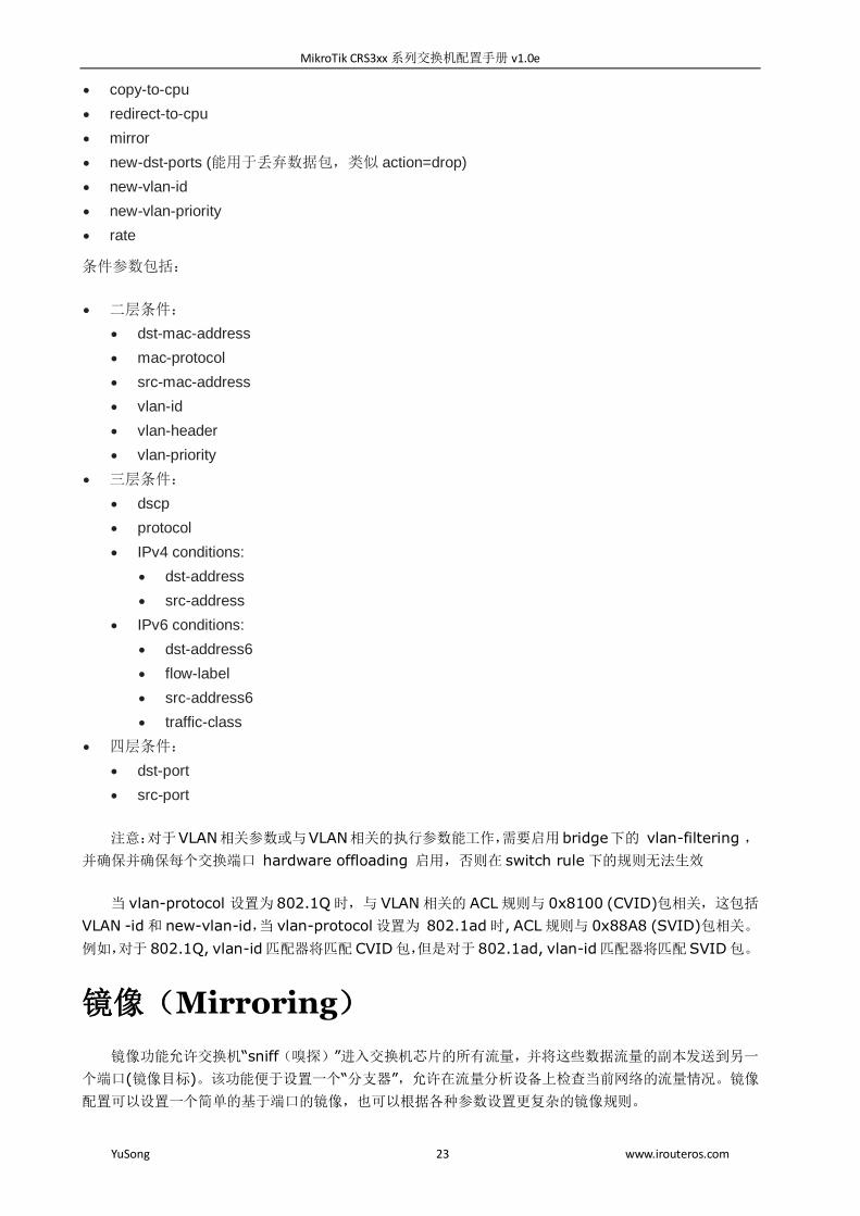
执行参数包括:
MikroTik CRS3xx 系列交换机配置手册 v1.0e
YuSong 23 www.irouteros.com
copy-to-cpu
redirect-to-cpu
mirror
new-dst-ports (能用于丢弃数据包,类似 action=drop)
new-vlan-id
new-vlan-priority
rate
条件参数包括:
二层条件:
dst-mac-address
mac-protocol
src-mac-address
vlan-id
vlan-header
vlan-priority
三层条件:
dscp
protocol
IPv4 conditions:
dst-address
src-address
IPv6 conditions:
dst-address6
flow-label
src-address6
traffic-class
四层条件:
dst-port
src-port
注意:对于VLAN相关参数或与VLAN相关的执行参数能工作,需要启用bridge下的 vlan-filtering ,
并确保并确保每个交换端口 hardware offloading 启用,否则在 switch rule 下的规则无法生效
当 vlan-protocol 设置为 802.1Q 时,与 VLAN 相关的 ACL 规则与 0x8100 (CVID)包相关,这包括
VLAN -id 和 new-vlan-id,当 vlan-protocol 设置为 802.1ad 时, ACL 规则与 0x88A8 (SVID)包相关。
例如,对于 802.1Q, vlan-id匹配器将匹配 CVID包,但是对于 802.1ad, vlan-id匹配器将匹配SVID包。
镜像(Mirroring)
镜像功能允许交换机“sniff(嗅探)”进入交换机芯片的所有流量,并将这些数据流量的副本发送到另一
个端口(镜像目标)。该功能便于设置一个“分支器”,允许在流量分析设备上检查当前网络的流量情况。镜像
配置可以设置一个简单的基于端口的镜像,也可以根据各种参数设置更复杂的镜像规则。

MikroTik CRS3xx 系列交换机配置手册 v1.0e
YuSong 24 www.irouteros.com
注意:做镜像配置时,目标和源镜像端口必须在相同switch下(同一交换芯片),可以通过命令/interface
Ethernet print 查看:
[admin@MikroTik] /interface ethernet> print
Flags: X - disabled, R - running, S - slave
# NAME MTU MAC-ADDRESS ARP SWITCH
0 S ether1 1500 CC:2D:E0:A3:EA:51 enabled switch1
1 RS ether2 1500 CC:2D:E0:A3:EA:52 enabled switch1
2 RS ether3 1500 CC:2D:E0:A3:EA:53 enabled switch1
3 RS ether4 1500 CC:2D:E0:A3:EA:54 enabled switch1
4 RS ether5 1500 CC:2D:E0:A3:EA:55 enabled switch1
如上面看到的,ether1-ether5都在switch1下,此外,镜像目标可以指定给“cpu”值,这意味着“sniffed”
数据将从交换芯片传到 CPU 端口发送出去,即交给系统处理镜像流量。
基于端口的镜像配置,这个配置是在 switch1 交换芯片下,将 ether2 的流量镜像到 ether3:
/interface ethernet switch
set switch1 mirror-source=ether2 mirror-target=ether3
mirror-source 参数将发送端口进和出拷贝数据给 mirror-target 端口,
mirror-source 和 mirror-target两个参数,都只能设置 1 个端口。但我们可以通过 ACL 策略,将多个源
端口镜像到一个mirror-target端口,如下配置:
/interface ethernet switch
set switch1 mirror-source=none mirror-target=ether3
/interface ethernet switch rule
add mirror=yes ports=ether1,ether2 switch=switch1
下面是一个基于 VLAN 的镜像配置
/interface bridge
set bridge1 vlan-filtering=yes
/interface ethernet switch
set switch1 mirror-target=ether3 mirror-source=none
/interface ethernet switch rule
add mirror=yes ports=ether1 switch=switch1 vlan-id=11
注意:通过启用 vlan-filtering ,镜像策略可以过滤流量给 CPU,在配置之前需要先配置 Management
port(管理端口)
基于 MAC 地址的镜像配置
/interface ethernet switch
set switch1 mirror-target=ether3 mirror-source=none
/interface ethernet switch rule
add mirror=yes ports=ether1 switch=switch1
dst-mac-address=64:D1:54:D9:27:E6/FF:FF:FF:FF:FF:FF

MikroTik CRS3xx 系列交换机配置手册 v1.0e
YuSong 25 www.irouteros.com
add mirror=yes ports=ether1 switch=switch1
src-mac-address=64:D1:54:D9:27:E6/FF:FF:FF:FF:FF:FF
基于协议的镜像配置
/interface ethernet switch
set switch1 mirror-target=ether3 mirror-source=none
/interface ethernet switch rule
add mirror=yes ports=ether1 switch=switch1 mac-protocol=ipx
基于 IP 地址的镜像配置
/interface ethernet switch
set switch1 mirror-target=ether3 mirror-source=none
/interface ethernet switch rule
add mirror=yes ports=ether1 switch=switch1 src-address=192.168.88.0/24
add mirror=yes ports=ether1 switch=switch1 dst-address=192.168.88.0/24
在 ACL 规则中,还有其他参数选项可以设置,可以参考 ACL 规则属性描述。
流量控制 (QoS)
对于 CRS3xx 系列交换机,支持硬件级的二层 QoS 流控策略,包括接口的入和出流量控制,也支持基
于 MAC、VLAN、IP 地址和协议的 QoS 策略。这些 QoS 配置都在 switch 菜单下操作,该流控规则是交由
交换芯片处理,请区别 RouterOS 系统的 Queue 流控,Queue 下的规则是要消耗 CPU 资源。
基于端口出入方向的 QoS 规则
/interface ethernet switch port
set ether1 ingress-rate=10M egress-rate=5M
基于 MAC 的 QoS 规则配置
/interface ethernet switch rule
add ports=ether1 switch=switch1
src-mac-address=64:D1:54:D9:27:E6/FF:FF:FF:FF:FF:FF rate=10M
基于 VLAN 的 QoS 规则配置
/interface bridge
set bridge1 vlan-filtering=yes
/interface ethernet switch rule
add ports=ether1 switch=switch1 vlan-id=11 rate=10M
基于 IP 的 QoS 规则配置
MikroTik CRS3xx 系列交换机配置手册 v1.0e
YuSong 26 www.irouteros.com
/interface ethernet switch rule add ports=ether1 switch=switch1
src-address=192.168.88.8/32 rate=30M
基于协议的 QoS 规则配置
/interface ethernet switch rule
add ports=ether1 switch=switch1 mac-protocol=ipx rate=10M
关于 QoS 限制的其他参数,可以查阅 ACL 部分.
注意:CRS3xx 交换策略规则数量,请查看之前的列表确认能配置多少规则
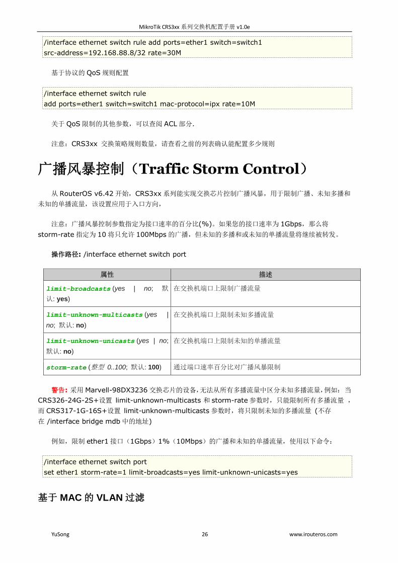
广播风暴控制(Traffic Storm Control)
从 RouterOS v6.42 开始,CRS3xx 系列能实现交换芯片控制广播风暴,用于限制广播、未知多播和
未知的单播流量,该设置应用于入口方向,
注意:广播风暴控制参数指定为接口速率的百分比(%)。如果您的接口速率为 1Gbps,那么将
storm-rate 指定为 10 将只允许 100Mbps 的广播,但未知的多播和或未知的单播流量将继续被转发。
操作路径: /interface ethernet switch port
属性 描述
limit-broadcasts (yes | no; 默
认: yes)
在交换机端口上限制广播流量
limit-unknown-multicasts (yes |
no; 默认: no)
在交换机端口上限制未知多播流量
limit-unknown-unicasts (yes | no;
默认: no)
在交换机端口上限制未知的单播流量
storm-rate (整型 0..100; 默认: 100) 通过端口速率百分比对广播风暴限制
警告: 采用 Marvell-98DX3236 交换芯片的设备,无法从所有多播流量中区分未知多播流量,例如: 当
CRS326-24G-2S+设置 limit-unknown-multicasts 和 storm-rate 参数时,只能限制所有多播流量 ,
而 CRS317-1G-16S+设置 limit-unknown-multicasts 参数时,将只限制未知的多播流量 (不存
在 /interface bridge mdb 中的地址)
例如,限制 ether1 接口(1Gbps)1%(10Mbps)的广播和未知的单播流量,使用以下命令:
/interface ethernet switch port
set ether1 storm-rate=1 limit-broadcasts=yes limit-unknown-unicasts=yes
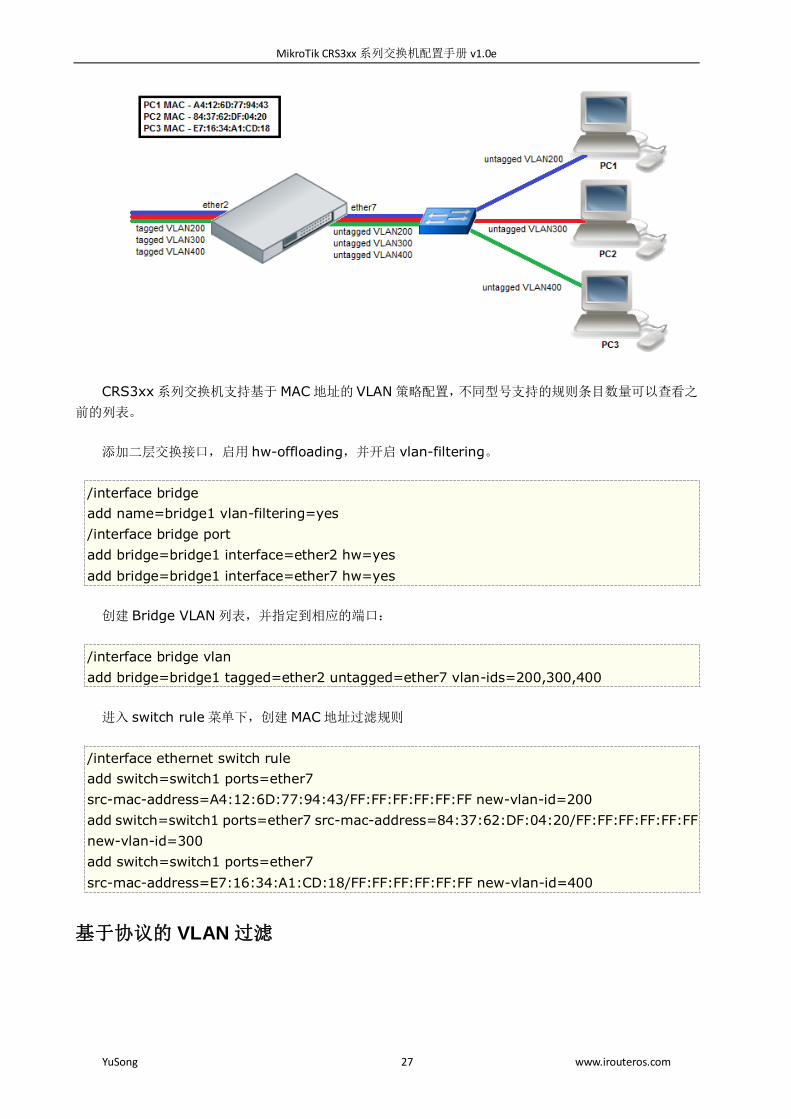
基于 MAC 的 VLAN 过滤
MikroTik CRS3xx 系列交换机配置手册 v1.0e
YuSong 27 www.irouteros.com
CRS3xx 系列交换机支持基于 MAC 地址的 VLAN 策略配置,不同型号支持的规则条目数量可以查看之
前的列表。
添加二层交换接口,启用 hw-offloading,并开启 vlan-filtering。
/interface bridge
add name=bridge1 vlan-filtering=yes
/interface bridge port
add bridge=bridge1 interface=ether2 hw=yes
add bridge=bridge1 interface=ether7 hw=yes
创建 Bridge VLAN 列表,并指定到相应的端口:
/interface bridge vlan
add bridge=bridge1 tagged=ether2 untagged=ether7 vlan-ids=200,300,400
进入 switch rule 菜单下,创建 MAC 地址过滤规则
/interface ethernet switch rule
add switch=switch1 ports=ether7
src-mac-address=A4:12:6D:77:94:43/FF:FF:FF:FF:FF:FF new-vlan-id=200
add switch=switch1 ports=ether7 src-mac-address=84:37:62:DF:04:20/FF:FF:FF:FF:FF:FF
new-vlan-id=300
add switch=switch1 ports=ether7
src-mac-address=E7:16:34:A1:CD:18/FF:FF:FF:FF:FF:FF new-vlan-id=400
基于协议的 VLAN 过滤

MikroTik CRS3xx 系列交换机配置手册 v1.0e
YuSong 28 www.irouteros.com
CRS3xx 系列交换机支持基于协议地址的 VLAN 策略配置,不同型号支持的规则条目数量可以查看之
前的列表。
添加二层交换接口,启用 hw-offloading,并开启 vlan-filtering。
/interface bridge
add name=bridge1 vlan-filtering=yes
/interface bridge port
add bridge=bridge1 interface=ether2 hw=yes
add bridge=bridge1 interface=ether6 hw=yes
add bridge=bridge1 interface=ether7 hw=yes
add bridge=bridge1 interface=ether8 hw=yes
创建 Bridge VLAN 列表,并指定到相应的端口:
/interface bridge vlan
add bridge=bridge1 tagged=ether2 untagged=ether6 vlan-ids=200
add bridge=bridge1 tagged=ether2 untagged=ether7 vlan-ids=300
add bridge=bridge1 tagged=ether2 untagged=ether8 vlan-ids=400
在 switch rule 菜单下,创建对应 VLAN id 的 MAC 协议过滤规则
/interface ethernet switch rule
add mac-protocol=ip new-vlan-id=200 ports=ether6 switch=switch1
add mac-protocol=ipx new-vlan-id=300 ports=ether7 switch=switch1
add mac-protocol=0x80F3 new-vlan-id=400 ports=ether8 switch=switch1
端口安全(Port Security)
在CRS3xx系列支持一个交换端口通过一个MAC地址。例如:在 ether1只允许64:D1:54:81:EF:8E
通过,并能与其他交换端口通信
创建两条 ACL 规则,允许 ether1 端口指定的 MAC 地址通过,并丢弃其他所有数据(入方向策略):
/interface ethernet switch rule
add ports=ether1 src-mac-address=64:D1:54:81:EF:8E/FF:FF:FF:FF:FF:FF switch=switch1
MikroTik CRS3xx 系列交换机配置手册 v1.0e
YuSong 29 www.irouteros.com
add new-dst-ports="" ports=ether1 switch=switch1
将 ether1 和 ether2 加入交换端口,并禁用 ether1 的 MAC 学习和 unknown-unicast-flood 功能:
/interface bridge
add name=bridge1
/interface bridge port
add bridge=bridge1 interface=ether1 hw=yes learn=no unknown-unicast-flood=no
add bridge=bridge1 interface=ether2 hw=yes
在 host 列表中添加静态 MAC 条目,用于出方向:
/interface bridge host
add bridge=bridge1 interface=ether1 mac-address=64:D1:54:81:EF:8E
警告: 广播流量仍将从 ether1 发送出去。要限制 bridge 端口的广播流量,需要使用 broadcast-flood
参数。请注意,有些协议依赖于广播流量,如流协议和 DHCP 。
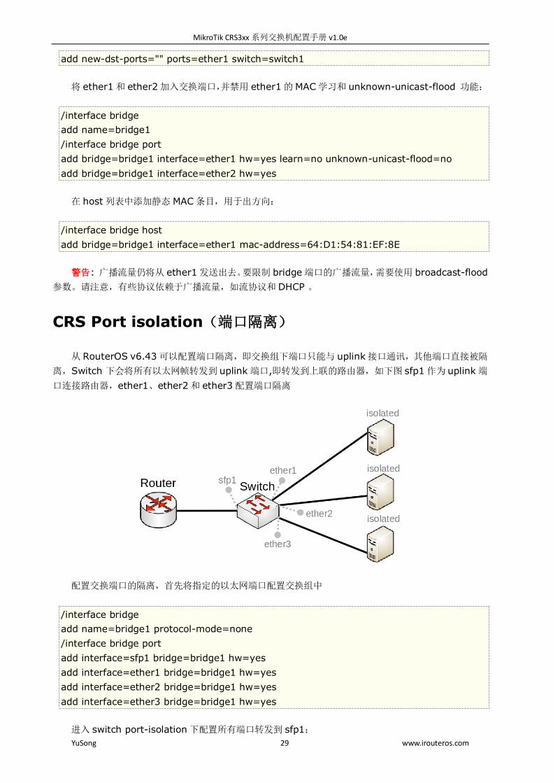
CRS Port isolation(端口隔离)
从 RouterOS v6.43 可以配置端口隔离,即交换组下端口只能与 uplink 接口通讯,其他端口直接被隔
离,Switch 下会将所有以太网帧转发到 uplink 端口,即转发到上联的路由器,如下图 sfp1 作为 uplink 端
口连接路由器,ether1、ether2 和 ether3 配置端口隔离
配置交换端口的隔离,首先将指定的以太网端口配置交换组中
/interface bridge
add name=bridge1 protocol-mode=none
/interface bridge port
add interface=sfp1 bridge=bridge1 hw=yes
add interface=ether1 bridge=bridge1 hw=yes
add interface=ether2 bridge=bridge1 hw=yes
add interface=ether3 bridge=bridge1 hw=yes
进入 switch port-isolation 下配置所有端口转发到 sfp1:
MikroTik CRS3xx 系列交换机配置手册 v1.0e
YuSong 30 www.irouteros.com
/interface ethernet switch port-isolation
set ether1 forwarding-override=sfp1
set ether2 forwarding-override=sfp1
set ether3 forwarding-override=sfp1
注意: 在同一个交换芯片下,允许配置多个 uplink 端口,指定多个 uplink 端口在命令行下通过逗号隔离
第四章 (R)STP
RouterOS Bridge 接口支持 STP 生成树协议,通过冗余拓扑避免二层环路出现。对于只有 2 个左右交
换节点的小型网络来说,STP 不会带来太多好处,但是对于较大的网络,正确配置 STP 是非常重要的。如
果将 STP 相关值设为默认值可能会导致二层网络出现异常,甚至网络完全不可达,为了实现冗余拓扑,需
要正确设置 Bridge 的优先级、端口路径成本和端口优先级。
STP 协议有多版本,目前 RouterOS 支持 STP、RSTP 和 MSTP。CRS3xx 完全支持 hardware
offloading 对该协议加速,完全由交换芯片完成。
STP协议现在几乎被 RSTP所取代,在所有的网络拓扑中,RSTP 是向后兼容 STP 的。对于依赖于 VLAN
的网络拓扑,建议使用 MSTP,MSTP 支持 VLAN 协议,并且能够对每个 VLAN 组进行负载平衡。在设计
一个支持 STP 的网络时需要考虑很多问题,更详细的案例研究请自行查阅 STP 生成树协议。
RouterOS 在配置 STP 时,通常建议手动设置每个 Bridge 的优先级、端口优先级和端口路径成本,以
确保二层网络转发正常。对于启用(R/M)STP 的由 1 到 2 个交换节点组成的网络,将 STP 相关值保留为默
认值是可以接受的,但是强烈建议为较大的网络手动设置。由于 STP 通过检查二层网络上的交换节点的 STP
相关值来选择 root(根),如果将 STP 设置为 automatic(自动),可能出现选择到不正确的 root 节点,
出现一些不确定的网络故障,导致网络无法正常通信。
在 RouterOS 上,可以通过/interface bridge monitor ,查看 STP 状态:
/interface bridge monitor bridge
state: enabled
current-mac-address: 64:D1:54:D9:27:E6
root-bridge: yes
root-bridge-id: 0x3000.64:D1:54:D9:27:E6
root-path-cost: 0
root-port: none
port-count: 5
designated-port-count: 5
查看接口的 STP 状态,通过命令 /interface bridge port monitor ,如下查看 ether3 端口
/interface bridge port monitor 2
interface: ether3
status: in-bridge
port-number: 3
MikroTik CRS3xx 系列交换机配置手册 v1.0e
YuSong 31 www.irouteros.com
role: root-port
edge-port: no
edge-port-discovery: yes
point-to-point-port: yes
external-fdb: no
sending-rstp: yes
learning: yes
forwarding: yes
root-path-cost: 10
designated-bridge: 0x3000.64:D1:54:D9:27:E6
designated-cost: 0
designated-port-number: 4
hw-offload-group: switch1
注意,root-bridge-id 由 bridge 的优先级和 bridge 的 MAC 地址组成,对于非根 bridge,将显示为
designated-bridge。在启用 STP 的网络中,每个端口会有一个角色状态,下面是端口可能的角色列状态
表:
根端口(Root Port):根端口存在于非根 bridge 上,该端口具备到根 bridge 的最佳路径(Path Cost)。
指定端口(Designated Port):Designated Port 存在于根 Bridge 和非根 Bridge,通常根 Bridge
上的所有端口都是 Designated Port,而对于非根 Bridge 来说,Designated Port 是指根据需要接
收数据或向根 bridge 转发数据的端口。
替代端口(Alternate Port):该类端口为当前"root 端口"到"root bridge"提供一条替代切换路径。
作为根端口的备份端口
备份端口(Backup Port):作为指定端口的备份, "备份端口"仅当一个 Bridge 节点的两个端口在
一个点对点的出现环路时,或者当交换机有两个或多个到达一个 LAN 网络的连接时可以存在。
禁用端口(Disabled Port):该类端口在生成树操作中没有担当任何角色,不参与 RSTP 运算。
当启用 bridge,并设置为 802.1Q 协议,它们将发送 BPDU 到 01:80:C2:00:00:00,这些 BPDU
被 MSTP、RSTP 和 STP 使用。当使用 802.1ad 作为 bridge VLAN 协议时,BPDU 与 802.1Q 网桥不兼
容,并发送到 01:80:C2:00:00:08。如果在第二层网络上存在不同的 VLAN 协议,STP 将无法正常工作。
STP 和 RSTP
STP 和 Rapid STP 在许多网络中被广泛使用,几乎所有的网络都在使用 RSTP,因为它的优点。STP
是一种非常古老的协议,它的收敛时间(完全了解网络拓扑变化和继续正确转发流量所需的时间)甚至可以达
到 50 秒,这在 20 世纪 80 年代发明 STP 时是可以接受的。RSTP 有很多更小的收敛时间,几秒甚至几毫
秒),更适应现在的网络要求。建议使用 RSTP 而不是 STP,因为 RSTP 收敛时间更快,而且与 STP 向后兼
容。RSTP 更快的原因之一是端口状态减少了,下面是 STP 端口状态列表:
Forwarding -端口参与流量转发,正在学习 MAC 地址,正在接收 BPDUs。
Listening -端口不参与流量转发,不学习 MAC 地址,正在接收 BPDUs。
Learning -端口不参与流量转发,但正在学习 MAC 地址
Blocking -端口被阻塞,因为它正在导致循环,但正在接收
Disabled -端口被禁用或不活动。

MikroTik CRS3xx 系列交换机配置手册 v1.0e
YuSong 32 www.irouteros.com
在 RSTP 中,disabled、listening 和 blocking 端口状态被替换为 Discarding 状态:
Forwarding -端口参与流量转发,正在学习 MAC 地址,正在接收 BPDUs (forwarding=yes).
Learning -端口不参与流量转发,但正在学习 MAC 地址(learning=yes).
Discarding -端口不参与流量转发,不学习 MAC 地址,正在接收 BPDUs (forwarding=no).
在 STP 中,Bridge 之间的连接是通过在相邻 Bridge 之间发送和接收 BPDU 来确定的。指定的端口将
BPDUs 发送到 root 端口。如果 BPDU 连续 3 次未接收到 HelloTime,则认为连接不可用,网络拓扑将开
始收敛。STP 可以通过减少 forward-delay 值,来减少特定场景下的收敛时间,该值用于处理端口
learning/listening 状态的时长。
在 RouterOS 中,可以指定哪些 Bridge 端口是边缘端口(Edge port)。边缘端口是不应该接收任何
BPDU 的端口,这样允许 STP 跳过学习和监听状态,直接进入转发状态。该特性有时被称为 PortFast,此
参数保留为默认值,即 auto,但也可以手动指定。手动将端口设置为边缘端口,通常这些是 access 端口。
RouterOS 不会根据当前端口的链路速率改变路径成本值,对于 10M、100M、1000M 和 10000M
速率的以太网端口被添加到 bridge port 中时,默认的路径成本值是 10(wlan 端口默认是 100)。
BPDU 的生成周期取决于 BPDU 通过 Bridge 的数量乘以 message age 值,因为 RouterOS 使用 1
作为消息生成周期增量,所以 BPDU 包可以通过 max-message-age 参数中指定 bridge 的数量。默认情
况下,这个值设置为 20,这意味着经过 20 个 Bridge 后,BPDU 报文后会被丢弃。如果出现下一个 Bridge
将成为一个新的 STP 节点网络。如果在使用 bridge 过滤规则时,确保允许 DST-MAC 地址为
01:80:C2:00:00:00 的数据包通过,因为这些数据包携带 STP 正常工作的 BPDU 信息。
BPDU(Bridge Protocol Data Unit,桥协议数据单元):用于网桥之间传递 BPDU 来交互协议信
息。BPDU 分为配置 BPDU 和 TCN BPDU。配置 BPDU 用来进行生成树的计算和维护生成树拓扑的报文,
TCN BPDU 是当拓扑结构改变时候,用来通知相关桥设备网络拓扑结构发生变化的报文。
BPDU 包含类型:
Flags:由 8 位组成,最低位为 TC 标志位,最高位为 TCA 标志位,其他 6 位保留。当拓扑结构变
化时候,下游 Bridge 将会从根端口发送 TCN BPDU 报文,TC 标志位置为 1,上游 Bridge 收到
后进行相应处理,回复配置 BPDU 报文,TCA 标志位置为 1.
Root Identifier:根桥 ID,包含优先级和 MAC 地址,标识网络中的根桥。
Root Path Cost:根路径成本,指从发送该配置 BPDU 的 Bridge 到根 Bridge 的最小路径开销,
总路径成本是所有途径链路开销之和。
Bridge Identifier:发送该配置 BPDU 的 Bridge ID,即该指定 Bridge 的 ID。
Port Identifier:发送该配置 BPDU 的 Bridge 发送端口 ID。
Message Age:从根 Bridge 生成配置 BPDU 开始,到当前时间为止配置 BPDU 的存活时间,配
置 BPDU 报文经过一个 Bridge,Message Age 增加 1。
Max Age:配置 BPDU 存活的最大时间。
Hello Time:根 Bridge 成并发送配置 BPDU 的周期。
Forward Delay:配置 BPDU 传播到全网的最大时延。
当创建一个 Bridge 或向 Bridge port 添加端口时,RouterOS 分配的 BPDU 默认值如下:
bridge priority: 32768 / 0x8000 (默认的 bridge 优先级)
bridge port path cost: 10 (默认的 bridge 端口路径成本)

MikroTik CRS3xx 系列交换机配置手册 v1.0e
YuSong 33 www.irouteros.com
bridge port priority: 0x80 (默认的 bridge 端口优先级)
BPDU message age : 1 (BPDU 消息的生存时间,如果配置 BPDU 是直接来自根 Bridge 的,则
Message Age 为 0,如果是其他桥转发的,则 Message Age 是从根桥发送到当前桥接收到 BPDU
的总时间,包括传输延时等。实际实现中,配置 BPDU 报文经过一个 Bridge,Message Age 增加
1)
HelloTime: 2 (发送两个相邻 BPDU 的时间间隔)
max message age: 20 (BPDU 消息的最大生存时间)
forward-delay:15s
选举过程
网络中如何正确配置 STP,需要了解 STP 节点的选举过程,在 RouterOS 中,根节点将根据最小优先
级值和最小 MAC 地址,按如下顺序选出:
1. Bridge priority (最小值)
2. Bridge MAC 地址 (最小值)
在 RouterOS 中,根端口是根据最低的端口路径成本、最低的 Bridge 标识符和最低的 Bridge 端口 ID
来选择的,顺序如下:
1. Port path cost(端口路径成本,最小值)
2. Bridge 标识 (最小值)
3. Bridge port ID (最小值)
注意: 确保在正确的端口上使用了路径成本和优先级。例如,在根节点中的端口上设置路径成本没有影
响,只有端口优先级对其有影响。路径成本对面向根节点的端口有影响,而端口优先级对面向 root 节点的
端口有影响
当选择一个 root 端口时,将首先检查路径成本。如果多条路径的路径成本相同,则检查 bridge 的标识
符。如果 bridge 标识符相同,则检查 bridge port ID,选择值最低的端口作为根端口。在设计启用 STP
的网络时,一定要考虑到选举过程。
警告: 在 RouterOS 中,Bridge 的 STP 优先级设置 0 到 65535 之间的任何值。根据 IEEE 802.1W
标准规定 Bridge 的优先级步进必须是 4096,如果随意设置,可能导致不支持这些值的设备出现不兼容性
问题。为了避免兼容性问题,建议只使用以下优先级:0、4096、8192、12288、16384、20480、24576、
28672、32768、36864、40960、45056、49152、53248、57344、61440
路径成本(Path cost)可在“/interface bridge port”下配置。网桥标识符(Bridge identifier)是
“bridge priority”和“bridge MAC”的组合,可在“/interface bridge”下配置,在默认值情况下,MAC 最
低的网桥路径将成为 root 端口。网桥端口 ID 是“唯一 ID”和“bridge port priority”的组合,该唯一 ID 添
加到网桥后自动分配给网桥端口,无法编辑。可以在“Bridge Port”“ Port Number”栏下的 WinBox 中看
到,也可以在“/interface bridge port monitor”中看到,作为“port-number”。
实例

MikroTik CRS3xx 系列交换机配置手册 v1.0e
YuSong 34 www.irouteros.com
在上面的实例中,4 台交换机组成了一个环线网络,并开启(R)STP,从 ServerA 到 ServerB 的连接
的需要建立二层冗余。当一个端口连接到一个不运行(R)STP 的设备时,这个端口被认为是一个边缘端口
(edge port),在这种情况下,ServerA 和 ServerB 连接到一个边缘端口。下面是每个交换机的配置示
例。
SW1 配置:
/interface bridge
add name=bridge priority=0x1000
/interface bridge port
add bridge=bridge interface=ether1 priority=0x60
add bridge=bridge interface=ether2 priority=0x50
add bridge=bridge interface=ether3 priority=0x40
add bridge=bridge interface=ether4 priority=0x30
add bridge=bridge interface=ether5
SW2 配置:
/interface bridge
add name=bridge priority=0x2000
/interface bridge port
add bridge=bridge interface=ether1
add bridge=bridge interface=ether2
add bridge=bridge interface=ether3
SW3 配置:

MikroTik CRS3xx 系列交换机配置手册 v1.0e
YuSong 35 www.irouteros.com
/interface bridge
add name=bridge priority=0x3000
/interface bridge port
add bridge=bridge interface=ether1
add bridge=bridge interface=ether2
add bridge=bridge interface=ether3
SW4 配置:
/interface bridge
add name=bridge priority=0x4000
/interface bridge port
add bridge=bridge interface=ether1
add bridge=bridge interface=ether2 path-cost=20
add bridge=bridge interface=ether3
在本例中,SW1 是 root 节点,它具有最低的 Bridge 优先级。SW2 和 SW3 的 ether1、ether2 连接
到 root Bridge,ether3 连接到 SW4。当所有交换机正常工作时,流量将从 ServerA 通过 SW1_ether2、
SW2、SW4 流向 ServerB。在 SW1 中断的情况下,由于较低优先级的 SW2 接替 root 节点。下面是每个
交换机的端口及其状态列表:
root-port - SW2_ether2, SW3_ether2, SW4_ether1
alternate-port - SW2_ether1, SW3_ether1, SW4_ether2
designated-port - SW1_ether1, SW1_ether2, SW1_ether3, SW1_ether4, SW1_ether5,
SW2_ether3, SW2_ether3, SW4_ether3
注意:根据 802.1W 建议,应该按照步进 4096 使用 Bridge 优先级。Bridge 优先级使用的是十六进
制表示法,例如,0 是 0x0000, 4096 是 0x1000, 8192 是 0x2000。因此在 RouterOS 设置时,winbox
看到 Bridge priority 默认值是 8000,是十六进制的,十进制其实为 32,768
第五章 其他应用和案例
IGMP Snooping(v6.41)
从 RouterOS v6.41 开始,在 bridge 中支持 ICMP Snooping,用于控制组播数据流。在 bridge 菜
单下设置组播参数,并独立工作在各个 bridge 接口下,所有 RouterOS 的设备都支持软件方式处理,只有
CRS1xx/2xx/3xx 系列支持 IGMP Snooping 的硬件处理。
操作路径: /interface bridge, /interface bridge mdb
在 Bridge 下启用 IGMP Snooping
/interface bridge set bridge1 igmp-snooping=yes

MikroTik CRS3xx 系列交换机配置手册 v1.0e
YuSong 36 www.irouteros.com
在 interface bridge mdb 下查看组播数据
[admin@MikroTik] > interface bridge mdb print
BRIDGE VID GROUP PORTS
bridge1 200 229.1.1.2 ether3
ether2
ether1
bridge1 300 231.1.3.3 ether4
ether3
ether2
bridge1 400 229.10.10.4 ether4
ether3
bridge1 500 234.5.1.5 ether5
ether1
[admin@MikroTik] >
IGMP 端口成员报告仅转发到连接到组播路由器或另一个启用 IGMP 监听的桥接端口。如果没有端口被
标记为组播路由器,那么 IGMP 端口成员将不会被转发到任何端口。
CRS 系列交换机的 hardware offloading 支持运行 IGMP snooping,但是 CRS1xx 和 CRS2xx 系
列交换机在配置了 VLAN 过滤功能后,IGMP Snooping 的 hardware offloading 功能将无法启用,即无
法由交换芯片处理 IGMP Snooping 功能,只能交给系统 CPU 处理。
DHCP Snooping 和 DHCP Option 82
从 RouterOS v6.43 开始,bridge 支持 DHCP Snooping 和 DHCP Option 82。DHCP Snooping
用于保障网络合法 DHCP 服务器的安全性,作用是屏蔽接入网络中的非法的 DHCP 服务器。在 RouterOS
上可以指定 bridge 的信任端口(已知 DHCP 服务器接入端口),并定义哪些是不可信的(通常用于 access
口,接收到的 DHCP 服务器消息将被丢弃)。DHCP Option 82 是一个附加信息(代理电路 ID 和代理远程
ID),由启用了 DHCP snooping 功能的设备提供,允许识别设备本身和 DHCP 客户端。
操作路径: /interface bridge ,/interface bridge port
配置实例:
MikroTik CRS3xx 系列交换机配置手册 v1.0e
YuSong 37 www.irouteros.com
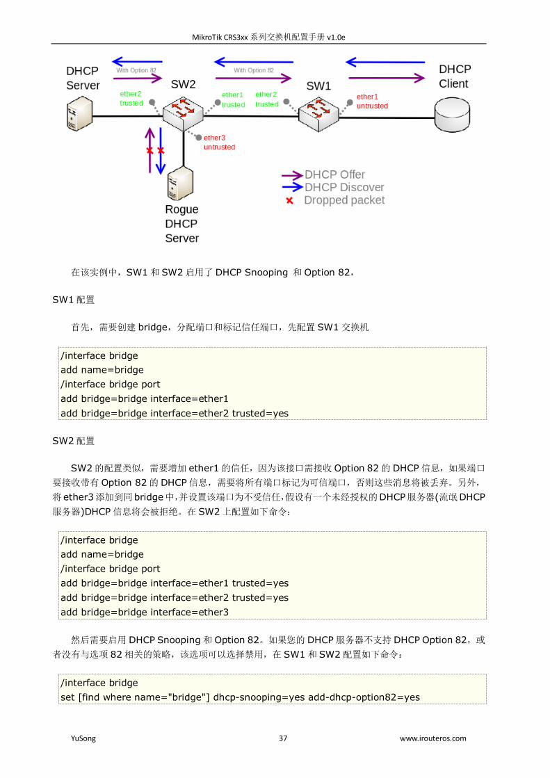
在该实例中,SW1 和 SW2 启用了 DHCP Snooping 和 Option 82,
SW1 配置
首先,需要创建 bridge,分配端口和标记信任端口,先配置 SW1 交换机
/interface bridge
add name=bridge
/interface bridge port
add bridge=bridge interface=ether1
add bridge=bridge interface=ether2 trusted=yes
SW2 配置
SW2 的配置类似,需要增加 ether1 的信任,因为该接口需接收 Option 82 的 DHCP 信息,如果端口
要接收带有 Option 82 的 DHCP 信息,需要将所有端口标记为可信端口,否则这些消息将被丢弃。另外,
将ether3添加到同bridge中,并设置该端口为不受信任,假设有一个未经授权的DHCP服务器(流氓DHCP
服务器)DHCP 信息将会被拒绝。在 SW2 上配置如下命令:
/interface bridge
add name=bridge
/interface bridge port
add bridge=bridge interface=ether1 trusted=yes
add bridge=bridge interface=ether2 trusted=yes
add bridge=bridge interface=ether3
然后需要启用 DHCP Snooping 和 Option 82。如果您的 DHCP 服务器不支持 DHCP Option 82,或
者没有与选项 82 相关的策略,该选项可以选择禁用,在 SW1 和 SW2 配置如下命令:
/interface bridge
set [find where name="bridge"] dhcp-snooping=yes add-dhcp-option82=yes
MikroTik CRS3xx 系列交换机配置手册 v1.0e
YuSong 38 www.irouteros.com
两台设备将分析在 bridge 端口上接收到的 DHCP 信息, SW1 负责添加和删除 DHCP Opton 82,
SW2 将限制恶意 DHCP 服务器从 ether3 接收任何信息。
当前 CRS3xx 系列完全支持 DHCP Snooping 和 Option 82 的交换芯片处理。对于 CRS1xx 和
CRS2xx 系列交换机,能实现 DHCP Snooping 通过 switch 菜单的配置,需要确保 DHCP 数据包通过
egress ACL 策略配置到正确的 VLAN 上。其他 RB 设备基于 hardware offloading 使用 DHCP Snooping
和 Option 82 功能,不能启用 VLAN 和相关的配置。
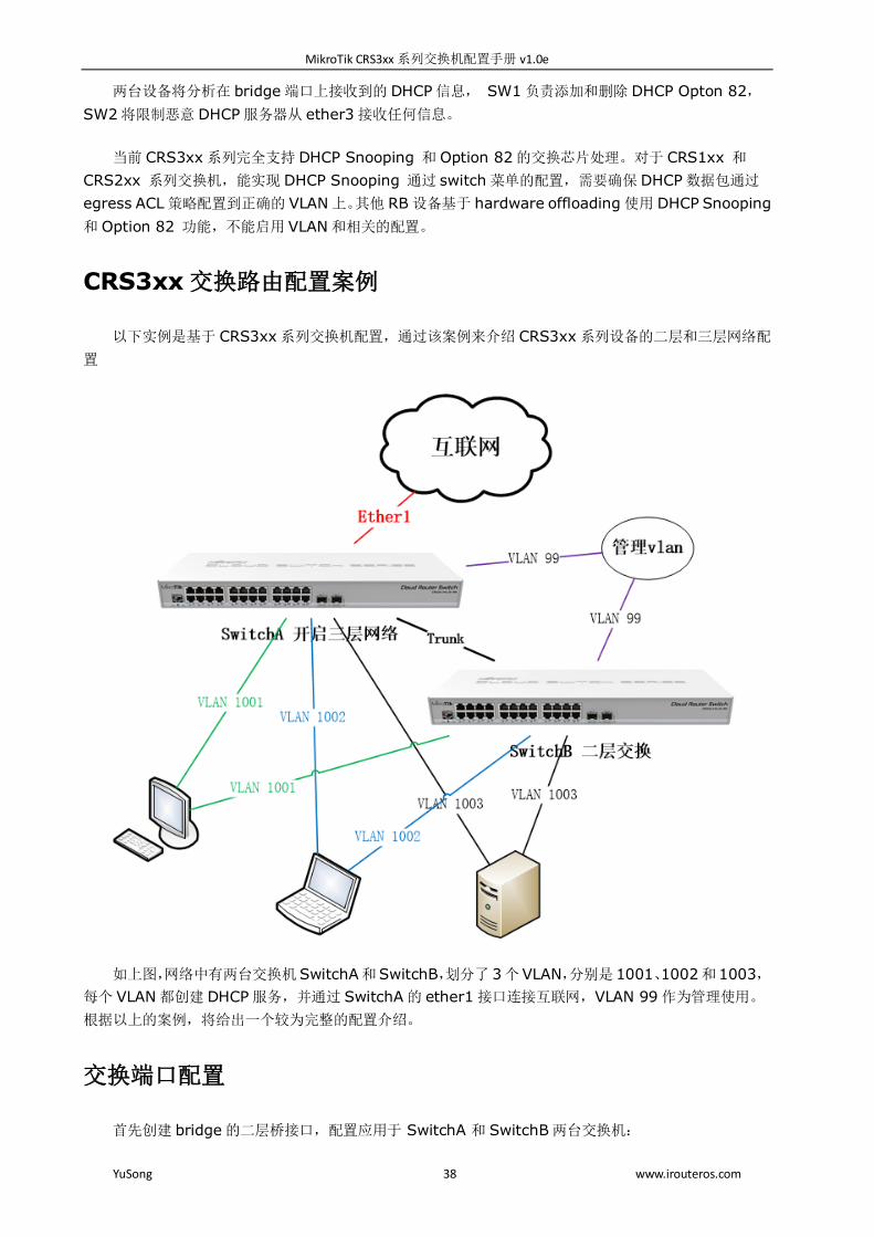
CRS3xx 交换路由配置案例
以下实例是基于 CRS3xx 系列交换机配置,通过该案例来介绍 CRS3xx 系列设备的二层和三层网络配
置
如上图,网络中有两台交换机SwitchA和SwitchB,划分了 3个VLAN,分别是1001、1002和1003,
每个 VLAN 都创建 DHCP 服务,并通过 SwitchA 的 ether1 接口连接互联网,VLAN 99 作为管理使用。
根据以上的案例,将给出一个较为完整的配置介绍。
交换端口配置
首先创建 bridge 的二层桥接口,配置应用于 SwitchA 和 SwitchB 两台交换机:
MikroTik CRS3xx 系列交换机配置手册 v1.0e
YuSong 39 www.irouteros.com
/interface bridge
add name=bridge vlan-filtering=no
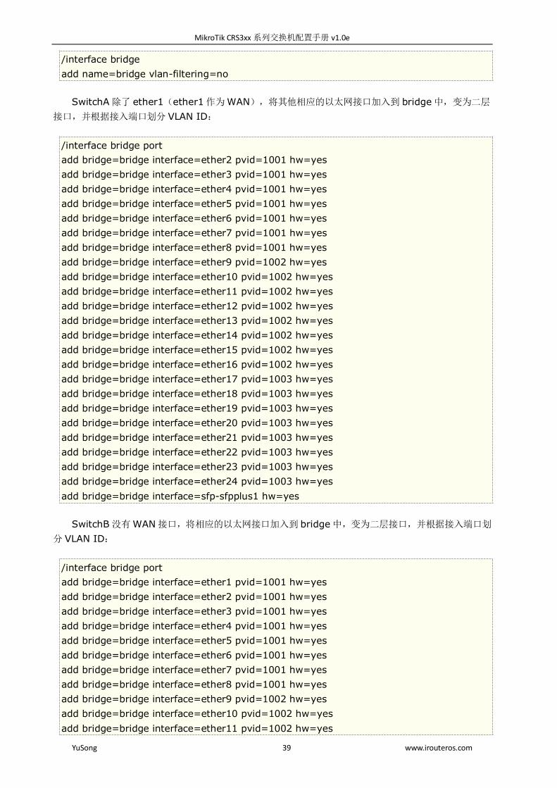
SwitchA 除了 ether1(ether1 作为 WAN),将其他相应的以太网接口加入到 bridge 中,变为二层
接口,并根据接入端口划分 VLAN ID:
/interface bridge port
add bridge=bridge interface=ether2 pvid=1001 hw=yes
add bridge=bridge interface=ether3 pvid=1001 hw=yes
add bridge=bridge interface=ether4 pvid=1001 hw=yes
add bridge=bridge interface=ether5 pvid=1001 hw=yes
add bridge=bridge interface=ether6 pvid=1001 hw=yes
add bridge=bridge interface=ether7 pvid=1001 hw=yes
add bridge=bridge interface=ether8 pvid=1001 hw=yes
add bridge=bridge interface=ether9 pvid=1002 hw=yes
add bridge=bridge interface=ether10 pvid=1002 hw=yes
add bridge=bridge interface=ether11 pvid=1002 hw=yes
add bridge=bridge interface=ether12 pvid=1002 hw=yes
add bridge=bridge interface=ether13 pvid=1002 hw=yes
add bridge=bridge interface=ether14 pvid=1002 hw=yes
add bridge=bridge interface=ether15 pvid=1002 hw=yes
add bridge=bridge interface=ether16 pvid=1002 hw=yes
add bridge=bridge interface=ether17 pvid=1003 hw=yes
add bridge=bridge interface=ether18 pvid=1003 hw=yes
add bridge=bridge interface=ether19 pvid=1003 hw=yes
add bridge=bridge interface=ether20 pvid=1003 hw=yes
add bridge=bridge interface=ether21 pvid=1003 hw=yes
add bridge=bridge interface=ether22 pvid=1003 hw=yes
add bridge=bridge interface=ether23 pvid=1003 hw=yes
add bridge=bridge interface=ether24 pvid=1003 hw=yes
add bridge=bridge interface=sfp-sfpplus1 hw=yes
SwitchB 没有 WAN 接口,将相应的以太网接口加入到 bridge 中,变为二层接口,并根据接入端口划
分 VLAN ID:
/interface bridge port
add bridge=bridge interface=ether1 pvid=1001 hw=yes
add bridge=bridge interface=ether2 pvid=1001 hw=yes
add bridge=bridge interface=ether3 pvid=1001 hw=yes
add bridge=bridge interface=ether4 pvid=1001 hw=yes
add bridge=bridge interface=ether5 pvid=1001 hw=yes
add bridge=bridge interface=ether6 pvid=1001 hw=yes
add bridge=bridge interface=ether7 pvid=1001 hw=yes
add bridge=bridge interface=ether8 pvid=1001 hw=yes
add bridge=bridge interface=ether9 pvid=1002 hw=yes
add bridge=bridge interface=ether10 pvid=1002 hw=yes
add bridge=bridge interface=ether11 pvid=1002 hw=yes

MikroTik CRS3xx 系列交换机配置手册 v1.0e
YuSong 40 www.irouteros.com
add bridge=bridge interface=ether12 pvid=1002 hw=yes
add bridge=bridge interface=ether13 pvid=1002 hw=yes
add bridge=bridge interface=ether14 pvid=1002 hw=yes
add bridge=bridge interface=ether15 pvid=1002 hw=yes
add bridge=bridge interface=ether16 pvid=1002 hw=yes
add bridge=bridge interface=ether17 pvid=1003 hw=yes
add bridge=bridge interface=ether18 pvid=1003 hw=yes
add bridge=bridge interface=ether19 pvid=1003 hw=yes
add bridge=bridge interface=ether20 pvid=1003 hw=yes
add bridge=bridge interface=ether21 pvid=1003 hw=yes
add bridge=bridge interface=ether22 pvid=1003 hw=yes
add bridge=bridge interface=ether23 pvid=1003 hw=yes
add bridge=bridge interface=ether24 pvid=1003 hw=yes
add bridge=bridge interface=sfp-sfpplus1
sfp-sfpplus2 接口在 SwitchA 和 SwitchB 不会使用,考虑安全为目的,禁用掉 sfp-sfpplus2 接口:
/interface ethernet set [find where name="sfp-sfpplus2"] disabled=yes
提示:创建 bridge 后,第一次初始化 VLAN 配置,在 bridge port 的 VLAN 配置完成前,出于安全考
虑,请不要开启 VLAN filtering 。
以上在 bridge port 下添加的接口,指定了 PVID,RouterOS 会自动在 bridge vlan 中创建 vlan id
关系,如果需要指定 trunk 口,需要进入 bridge vlan 菜单进行手动指定。
管理 VLAN
RouterOS 有多种方式添加一个管理端口,在该实例中,采用的是 VLAN 接口创建,通过标记 VLAN ID
99 作为管理 VLAN。
警告: 对于 CRS 系列于交换机并没有考虑将其设计成路由器,因此设置规则来限制一些不需要的流量
发送到 CPU 。必须记住这一点,三层转发和防火墙规则都会给 CPU 增加额外的负载。
管理 IP 地址分配:
SwitchA :192.168.99.1/24
SwitchB :192.168.99.2/24
SwitchA 进入 interface vlan 创建三层 vlan 接口,并取名 MGMT 接口
/interface vlan
add interface=bridge name=MGMT vlan-id=99
为 MGMT 接口配置管理 IP 地址:
/ip address
add address=192.168.99.1/24 interface=MGMT

MikroTik CRS3xx 系列交换机配置手册 v1.0e
YuSong 41 www.irouteros.com
SwitchB 也用同样的方式配置 IP 地址,并且配置默认路由指向 SwitchA 的 192.168.99.1 作为网关
/interface vlan
add interface=bridge name=MGMT vlan-id=99
/ip address
add address=192.168.99.2/24 interface=MGMT
/ip route
add gateway=192.168.99.1
在 SwitchA 和 SwitchB 配置 VLAN tag 标记 trunk 到 bridge 和 sfp-sfpplus1 接口,
tagged=bridge 代表将 vlan id 99 发送给 CPU,即三层数据交给 CPU 处理
/interface bridge vlan
add bridge=bridge tagged=bridge,sfp-sfpplus1 vlan-ids=99
注意,在该案例中, SWitchB 作为纯二层交换机,对于三层数据仅用于管理。 VLAN 99 的访问接口,
根据自身网络要求进行接口规划。对于三层网络访问管理 IP 地址限制,在 SwitchA 上可以通过 ip firewall
filte 或 switch rule 菜单进行 ACL 策略配置。
VLAN 配置
当每个端口被添加到 bridge 时,进入的流量将被标记到指定的 VLAN ID。需要将每个 VLAN ID 添加
到 VLAN 列表建立端口与 VLAN 的对应关系,tagged端口作为 trunk 端口,untagged 端口作为 access
端口。
注意,由于在该案例中交换机又将是一个路由器,对于三层以上的网络数据都会交给 CPU 处理,因此
必须将 bridge 端口加入到 tagged 标记,三层数据才能交给 CPU 处理。只有在交换机启用三层配置时,才
这样操作,否则在交换机上无法启用 DHCP 服务分配 IP 地址
在 SwitchA 的 bridge vlan 中设置 trunk 端口,并需要同时指定 access 口,如下配置:
/interface bridge vlan
add bridge=bridge tagged=sfp-sfpplus1,bridge
untagged="ether2,ether3,ether4,ether5,ether6,ether7,\
ether8" vlan-ids=1001
add bridge=bridge tagged=sfp-sfpplus1,bridge
untagged="ether9,ether10,ether11,ether12,ether13,\
ether14,ether15,ether16" vlan-ids=1002
add bridge=bridge tagged=sfp-sfpplus1,bridge
untagged="ether17,ether18,ether19,ether20,ether21,\
ether22,ether23,ether24" vlan-ids=1003
类似地,在 SwitchB 交换机配置 VLAN 列表,这里 bridge 没有被添加到 tagged 下,因为没有三层
数据要交给 CPU 处理
/interface bridge vlan
MikroTik CRS3xx 系列交换机配置手册 v1.0e
YuSong 42 www.irouteros.com
add bridge=bridge tagged=sfp-sfpplus1
untagged="ether1,ether2,ether3,ether4,ether5,ether6,ether7,\
ether8" vlan-ids=1001
add bridge=bridge tagged=sfp-sfpplus1
untagged="ether9,ether10,ether11,ether12,ether13,ether14,\
ether15,ether16" vlan-ids=1002
add bridge=bridge tagged=sfp-sfpplus1
untagged="ether17,ether18,ether19,ether20,ether21,ether22,\
ether23,ether24" vlan-ids=1003
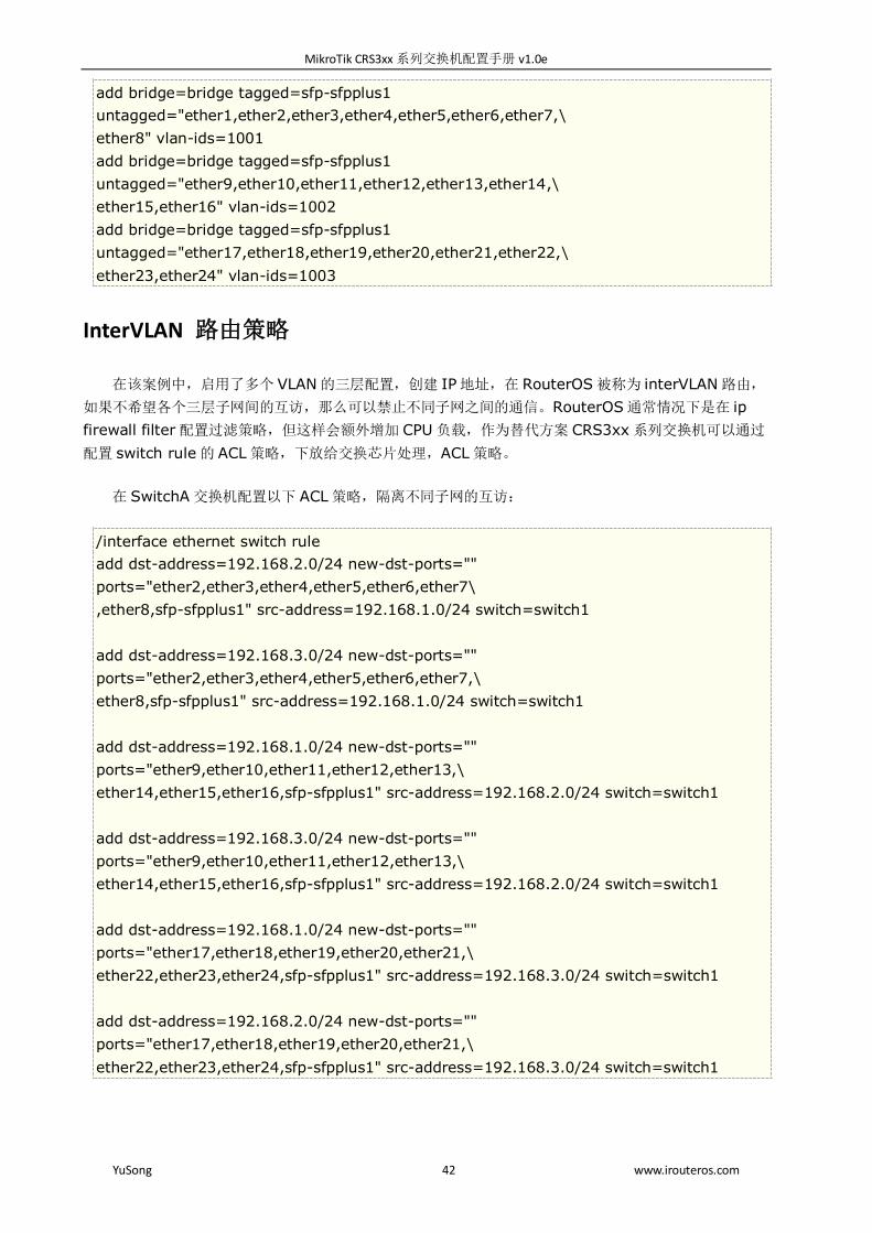
InterVLAN 路由策略
在该案例中,启用了多个 VLAN 的三层配置,创建 IP地址,在 RouterOS 被称为 interVLAN 路由,
如果不希望各个三层子网间的互访,那么可以禁止不同子网之间的通信。RouterOS 通常情况下是在 ip
firewall filter 配置过滤策略,但这样会额外增加 CPU 负载,作为替代方案 CRS3xx 系列交换机可以通过
配置 switch rule 的 ACL 策略,下放给交换芯片处理,ACL 策略。
在 SwitchA 交换机配置以下 ACL 策略,隔离不同子网的互访:
/interface ethernet switch rule
add dst-address=192.168.2.0/24 new-dst-ports=""
ports="ether2,ether3,ether4,ether5,ether6,ether7\
,ether8,sfp-sfpplus1" src-address=192.168.1.0/24 switch=switch1
add dst-address=192.168.3.0/24 new-dst-ports=""
ports="ether2,ether3,ether4,ether5,ether6,ether7,\
ether8,sfp-sfpplus1" src-address=192.168.1.0/24 switch=switch1
add dst-address=192.168.1.0/24 new-dst-ports=""
ports="ether9,ether10,ether11,ether12,ether13,\
ether14,ether15,ether16,sfp-sfpplus1" src-address=192.168.2.0/24 switch=switch1
add dst-address=192.168.3.0/24 new-dst-ports=""
ports="ether9,ether10,ether11,ether12,ether13,\
ether14,ether15,ether16,sfp-sfpplus1" src-address=192.168.2.0/24 switch=switch1
add dst-address=192.168.1.0/24 new-dst-ports=""
ports="ether17,ether18,ether19,ether20,ether21,\
ether22,ether23,ether24,sfp-sfpplus1" src-address=192.168.3.0/24 switch=switch1
add dst-address=192.168.2.0/24 new-dst-ports=""
ports="ether17,ether18,ether19,ether20,ether21,\
ether22,ether23,ether24,sfp-sfpplus1" src-address=192.168.3.0/24 switch=switch1
MikroTik CRS3xx 系列交换机配置手册 v1.0e
YuSong 43 www.irouteros.com
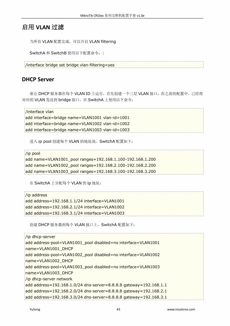
启用 VLAN 过滤
当所有 VLAN 配置完成,可以开启 VLAN filtering
SwitchA 和 SwitchB 使用以下配置命令::
/interface bridge set bridge vlan-filtering=yes
DHCP Server
要让 DHCP 服务器在每个 VLAN ID 上运行,首先创建一个三层 VLAN 接口,在之前的配置中,已经将
对应的 VLAN 发送到 bridge 接口,在 SwitchA 上使用以下命令:
/interface vlan
add interface=bridge name=VLAN1001 vlan-id=1001
add interface=bridge name=VLAN1002 vlan-id=1002
add interface=bridge name=VLAN1003 vlan-id=1003
进入 ip pool 创建每个 VLAN 的地址池,SwitchA 配置如下:
/ip pool
add name=VLAN1001_pool ranges=192.168.1.100-192.168.1.200
add name=VLAN1002_pool ranges=192.168.2.100-192.168.2.200
add name=VLAN1003_pool ranges=192.168.3.100-192.168.3.200
在 SwitchA 上分配每个 VLAN 的 ip 地址:
/ip address
add address=192.168.1.1/24 interface=VLAN1001
add address=192.168.2.1/24 interface=VLAN1002
add address=192.168.3.1/24 interface=VLAN1003
创建 DHCP 服务器到每个 VLAN 接口上,SwitchA 配置如下:
/ip dhcp-server
add address-pool=VLAN1001_pool disabled=no interface=VLAN1001
name=VLAN1001_DHCP
add address-pool=VLAN1002_pool disabled=no interface=VLAN1002
name=VLAN1002_DHCP
add address-pool=VLAN1003_pool disabled=no interface=VLAN1003
name=VLAN1003_DHCP
/ip dhcp-server network
add address=192.168.1.0/24 dns-server=8.8.8.8 gateway=192.168.1.1
add address=192.168.2.0/24 dns-server=8.8.8.8 gateway=192.168.2.1
add address=192.168.3.0/24 dns-server=8.8.8.8 gateway=192.168.3.1
MikroTik CRS3xx 系列交换机配置手册 v1.0e
YuSong 44 www.irouteros.com
nat 与防火墙
对于 CRS 系列而言,配置有三层网络访问时,有一个适当的防火墙来保护设备安全性是很重要的。对
于防火墙设置,使用大多数 RB 自带的默认防火墙就足够了。
警告:仍然需要提醒,nat 和防火墙每增加一条规则都会增加 CPU 开销,因此配置防火墙规则时需特
别注意。
配置 SwitchA 的 ether1 接口公网 IP 地址,并添加默认路由
/ip address
add address=10.10.10.2/24 interface=ether1
/ip route
add gateway=10.10.10.1
配置接口列表,应用于防火墙策略:
/interface list
add name=WAN
add name=LAN
/interface list member
add interface=bridge list=LAN
add interface=ether1 list=WAN
应用于 SwitchA 的三层防火墙规则:
/ip firewall filter
add action=accept chain=input connection-state=established,related,untracked
add action=drop chain=input connection-state=invalid
add action=accept chain=input protocol=icmp
add action=drop chain=input in-interface-list=!LAN
add action=accept chain=forward ipsec-policy=in,ipsec
add action=accept chain=forward ipsec-policy=out,ipsec
add action=fasttrack-connection chain=forward connection-state=established,related
add action=accept chain=forward connection-state=established,related,untracked
add action=drop chain=forward connection-state=invalid
add action=drop chain=forward connection-nat-state=!dstnat connection-state=new
in-interface-list=WAN
配置 nat 规则,访问互联网都伪装到 WAN 接口列表出去:
/ip firewall nat
add action=masquerade chain=srcnat ipsec-policy=out,none out-interface-list=WAN
为了获得额外的安全性,可以禁用除管理端口之外的所有端口上的邻居发现协议,配置在 SwitchA 和
SwitchB 上 :

MikroTik CRS3xx 系列交换机配置手册 v1.0e
YuSong 45 www.irouteros.com
/interface list
add name=neighbors
/interface list member
add interface=MGMT list=neighbors
/ip neighbor discovery-settings
set discover-interface-list=neighbors
参考 http://wiki.mikrotik.com
http://www.routerboard.com