Embed Size (px)
Citation preview

AD A155 785 NATIONAL PROORAU FOR INSPECTION OP NON 4FEDERAL 0*MS ~ gMANCHAUG POND O M..I(U) CORPS OF ENGINEERS WALTHM MA
/NEW ENGLAND DIV JUL S0 fG 13/13 NLIIIII"""II
mIIIIIIIIIIIIlIIIIIIIIIIIIIlIhIIIIIIIhIIIIIIIIIIIIIIl

- u .. UL
1.0 ~'~' I1.1 EdO 128
IMcROCOPY RESOLLJ101 TMS Cw4RTNtATIONALBUNtAA OF STANRMAMH-A
Li IMNbG~A 0I,
c0 BLACKSTONE RIVER BASIN
SUTTON, MASSACHUSETTS
I| MANCHAUG POND DAM
MA. 00955'I
I PHASE I INSPECTION REPORT
S1|NATIONAL DAM INSPECTION PROGRAM
iDTIC
i OIELECTEII
I !,DEPARTMENT OF THE ARMY
NEW ENGLAND DIVISION, CORPS OF ENGINEERSWALTHAM , MASS. 02154
DSRtMUON STATEMNT AEprwoed for publlc rel"
I Distbution UnumitodJULY 1980 I 049
,~K1 -11,06 '7

SECURITY CLASSIFICATION OF TMIS PAGE (110%on Doesa met.d)REPOT DCUMNTATON AGEREAD INSTRUCTIONS
REPOT DCUMNTATON AGEBEFORE COMPLETING FORM1REPORT NMBER 2. GOVT ACCESSION NO. 3. RECIPIENT*$ CATALOG NUMBER
4. TITLE (id Suabtitle) S. TYPE OF REPORT & PERIOD COVERED
Manchaug Pond Dam INSPECTION REPORT
NATIONAL PROGRAM FOR INSPECTION OF NON-FEDERAL 6. PERFORMING ORG. REPORT NUMBER
flAMS7. AUTNOR(.I 8. CONTRACT OR GRANT N6UMUERI'v)
U.S. ARMY CORPS OF ENGINEERSNEW ENG LAN D DIVISION
9. PERFORMING ORGANIZATION NAME AND ADDRESS 10. PROGRAM ELEMENT. PROJECT. TASKAREA II WORK UNIT NUMBERS
%I. CONTROLLING OFFICE NAME AND ADDRESS 12. REPORT DATS
DEPT. OF THE ARMY, CORPS OF ENGINEERS Jul 1980NEW ENGLAND DIVISION, NEDED Is. NuM11ER1 or PAGES
424 TRAPELO ROAD, WALTHAM, MA. 02254 554#. MONITORING AGENCY NAME G AORSS(If diaffIo Ie Cwt,.jIi, Off#@*) 11S. $SECURITY CLASS. (of Ohle -e"et
UNCLASSIFIEDIS.. Oacklm V PIC ATIO141 DOWNGRADING
1S. DISTRIBUTION STATEMENT (of Mhis ROPeat)
APPROVAL FOR PUBLIC RELEASE: DISTRIBUTION UNLIMITED
I7. DISTRIBUTION STATEMENT (f. the re ntred On 51mb M It Offereal btm Ampe-)
Ia. SUPPLEMENTARY NOTES
Cover program reads: Phase I Inspection Report, National Dam Inspection Program;however, the official title of the program is: National Program for Inspection ofNon-Federal Dams; use cover date for date of report.
it. KEy wOROS (C@,gmuoaen rewe. side ofgmaaeewaryddidmiifr p ieek nemsbe)
DAMS, INSPECTION, DAM SAFETY,Blacks tone River BasinSutton, Massachusetts
Unnamed Tributary to Mumford River
20. ABSTRACT (CORSR n. aueverieaEi meew aid-i04411F401 Odgetitr OF Wiaa* aMber)
-The dam is a composite rubble masonry and earthf ill structure about 330 ft. longand 28 ft. high. The dam Is Judged to be in generally good physical condition.Eiow~ver, because of the inadequate spillway discharge capacity, it is rated infair condition. The rubble masonry upstream face need minor repointing and the
right wall of the approach channel to the spillway should be repointed.It is intermediate .in size with a hazard potential of high1
DD I JAIN1? 1473 EDITION OP I NOV 65 IS OBSOLETIL

DISCLAIMER NOTICE
THIS DOCUMENT IS BEST QUALITYPRACTICABLE. THE COPY FURNISHEDTO DTIC CONTAINED A SIGNIFICANTNUMBER OF PAGES WHICH DO NOTREPRODUCE LEGIBLY.

DEPARTMENT OF THE ARMYNEW ENGLAND DIVISION. CORPS OF ENGINEERS
424 TRAPELO ROAD
WALTHAM. MASSACHUSETTS 02254
IREPLY TOATTENTION OF:NEDEDK
DEC 2 2 1980
aHonorable Edward J. KingGovernor of the Commonwealth of
MassachusettsState HouseBoston, Massachusetts 02133
YDear Governor King:
Inclosed is a copy of the Manchaug Pond Dam (MA-00955) Phase IInspection Report, which was prepared under the National Program forInspection of Non-Federal Dams. This report is presented for your use
1and is based upon a visual inspection, a review of the past performanceand a brief hydrological study of the dam. A brief assessment Is
Included at the beginning of the report. I have approved the report andsupport the findings and recommendations described in Section 7 and askthat you keep me informed of the actions taken to Implement them. Thisfollow-up action is a vitally important part of this program.
A copy of this report has been forwarded to the Department of Environ-mental Quality Engineering, the cooperating agency for the Commonwealthof Massachusetts. In addition, a copy of the report has also beenfurnished the owner, Mumford River Reservoir Association, Whitinsville,NA.
Copies of this report will be made available to the public, uponi request, by this office under the Freedom of Information Act. In the
case of this report the release date will be thirty days from the dateof this letter.
I wish to take this opportunity to thank you and the Department ofEnvironmental Quality Engineering for your cooperation in carrying outthis program.
Sincerely p,
Inc
As stated Colo 1, Corps of Engineers
ActiftS Division Engineer
LL
[- --- --,,-----,

III MANCHAUG POND DAM
Accession ForP MA 00955
DTIC TABrnami a so 1Justirfoutio _
Distriblution/ copy
AvailabilityC&OdSAvail and/er
Dist Special
I
I
PHASE I INSPECTION REPORT
NATIONAL DAM INSPECTION PORGRAM
I[
I
I
-n I

NATIONAL DAM INSPECTION PROGRAMj PHASE I INSPECTION REPORT
IIdentification NO.: MA 00955Name of Dam: Manchaug Pond DamTown: SuttonCounty and State: Worcester County, MassachusettsIStream: Unnamed Tributary to Mumford River
Date of Inspection: 15 April and 20 May 1980
BRIEF ASSESSMENT
IManchaug Pond Dam is a composite rubble masonry and earthfill structureabout 330 ft. long and 28 ft. high. The original dam was reconstructedjand raised in 1960. The dam's upstream face is of stepped, rubblemasonry construction and is the only exposed portion of the originaldam. When the dam was reconstructed an earthfill was placed over anexisting downstream stone wall and the downstream face now has a slopeIof 2 horizontal to 1 vertical. The crest width of the dam is 36 ft.and Torrey Road passes over the dam along its crest. The spillwayIfor the dam is a concrete box culvert. The culvert is 9.35 ft. highand has a crest length of 10.0 ft. at its entrance. There is a lowlevel outlet for the dam near the right abutment which is controlledIby an upstream sluice gate. The dam is used to store process andcooling water for mills located downstream on the Mumford River andthe pond is also used for recreation.
I The pond is about 8,000 ft. long and has a surface area at spillwaycrest level of about 350 acres. The drainage area above the dam isabout 6.6 sq. mi. (4,212 acres) and the maximum storage to top of damIis about 6,850 acre-ft. Based on height and storage the sizeclassification is intermediate. A breach of the dam would damage atleast ten homes, three public buildings, a mill complex, and three
* local roadways in the initial impact area; therefore, the dam has been* classified as having a high hazard potential. Based upon the guide-lines, the recommended test flood is a full PMF. The test flood inflowwas calculated to be 9,700 cfs.
IThe rovited test flood outflow of 3,400 cfs would overtop the dam byabout 2.0 ft. The spillway can pass about 880 cfs or 26 percent ofI the routed test flood outflow without overtopping the dam.
The dam is judged to be in generally good physical condition. However,Ibecause of the inadequate spillway discharge capacity, it is rated infair condition. The rubble masonry upstream face needs minor repointingand the right wall of the approach channel to the spillway should be
repointed.

I/'
Within one year after receipt of this Phase I Inspection Report, theowner, the Mumford River Reservoir Association, should retain theservices of a registered professional engineer, experienced in thedesign of dams, to make further investigations of the following,and should implement the results: (1) perform a detailed hydraulic andhydrologic analysis to further assess the need for and means toincrease the project discharge capacity; (2) inspect the inside ofthe box culvert spillway during a period of low flow or no flowconditions and determine whether repairs are needed.
The owner should also implement the following operating andmaintenance measures: (1) repair minor spalling of the mortared jointsof the upstream rubble masonry wall by repointing with mortar; (2)repair voids in the rubble masonry wall of the spillway approachchannel on the right side by repointing with mortar; (3) monitorseepage emanating from the 6 in. asphalt coated corrugated metal pipeat the toe of the dam and to the left of the spillway outlet toascertain any changes in clarity and quantity of flow; (4) developa formal surveillance and downstream emergency warning plan includinground-the-clock monitoring during periods of heavy precipitation;I (5) continue to conduct annual technical inspections of the dam andits appurtenant structures; (6) implement a regular periodic maintenance
program.I
I#
1 Peter C DysonProject ranager
OF A1OFISPETER
M~ANDYSON
$ No. 18452 0!I
II
* 1 -~....- - --........ -... . . . -.. . . .
I
This Phase I Inspection Report on Manchaug Pond Dam (MA-00955)has been revieved by the undersigned Review Board members. In ouropinion, the reported findings, conclusions, and recommendations areconsistent with the Recommended Guidelines for Safety Inspection of
i Dams, end with good engineering judgment and practice, and is herebysubmitted for approval.
i
I
1
I
IaARAMAST MAHTESIAN, MEMBER
Geotechnical Engineering BranchEngineering Division
1
CARNEY M. TERZIAN, MEMBERDesign BranchEngineering Division
Water Control BranchEngineering Division
t tSPPOYL RZCUMM D
"
Chief *f8sisseal Division
FD-.I . ..
-I. m me mm am

P REFACE
This report is prepared unde *r guidance contained in the Recommended Guidelinesfor Safety Inspection of Dams, for Phase I Investigations. Copies of theseI guidelines may be obtained from the Office of Chief of Engineers, Washington,D.C. 20314. The purpose of a Phase I Investigation is to identify expeditiouslythose dams which maj pose hazards to human life or property. The assessment ofthe general condition of the dam is based upon available data and visual inspec-tions. Detailed investigation, and analyses involving topographic mapping, sub-surface investigations, testing, and detailed computational evaluations are be-yond the scope of a Phase I investigation; however, the investigation is intended
to identify any need for such studies.
In reviewing this report, it should be realized that the reported condition ofIthe damn is based on observations of field conditions at the time of inspectionalong with data available to the inspection team. In cases where the reservoirwas lowered or drained prior to inspection, such action, while improving the
stability and safety of the dam, removes the normal load on the structure andmay obscure certain conditions which might otherwise be detectable if inspectedunder the normal operating environment of the structure.
It is important to note that the condition of a dam depends on numerous and con-stantly changing internal and external conditions, and is evolutionary in nature.It would be incorrect to assume that the present condition of the dam will con-tinue to represent the condition of the dam at some point in the future. Onlythrough continued care and inspection can there be any chance that unsafe con-
Iditions be detected.Phase I inspections are not intended to provide detailed hydrologic and hydraulicanalyses. In accordance with the established Guidelines, the Spillway Test Floodis based on the estimated "Probable Maximum Flood" for the region (greatestreasonably possible storm runoff), or fractions thereof. Because of the magni-tude and rarity of such a storm event, a finding that a spillway will not passthe test flood should not be interpreted as necessarily posing a highly inade-
quate condition. The test flood provides a measure of relative spillway capa-city and serves as an aide in determining the need for more detailed hydrologicand hydraul~ic studies, considering the size of the dam, its general condition
and the downstream damage potential.
The Phase I Investigation does not include an assessment of the need for fences,gates, no-trespassing signs, repairs to existing fences and railings and otheritems which may be needed to minimize trespass and provide greater security forthe facility and safety to the public. An evaluation of the project for comn-pliance with OSHA rules and regulations is also excluded.

TABLE OF CONTENTS
Section Pg
Letter of Transmittal
Brief Assessment
Review Board Page
Prefacei
Table of Contents i
Overview Photo v
Location Map vi
REPORT
1. PROJECT INFORMATION
1.1 General I
a. Authority Ib. Purpose of Inspection 1
1.2 Description of Project
a. Location 1b. Description of Dam and Appurtenances 1c. Size Classification 2d. Hazard Classification 3e. Ownership3f. Operator3g. Purpose of Dam 3h. Design and Construction History 3i. Normal Operational Procedure 3
1.3 Pertinent Data4
2. ENGINEERING DATA
2.1 Design Data 7
2.2 Construction Data 7
2.3 Operation Data7
2.4 Evaluation of Data7

Section Page
3. VISUAL INSPECTION
3.1 Findings 8
a. General
b. Damc. Appurtenant Structures 8d. Reservoir Area 9e. Downstream Channel 9
3.2 Evaluation 9
4. OPERATIONAL AND MAINTENANCE PROCEDURES
4.1 Operational Procedures 11
a. General 11b. Description of any Warning System in Effect 11
4.2 Maintenance Procedures ii
a. General 11b. Operating Facilities 11
4.3 Evaluation 11
5. EVALUATION OF HYDRAULIC/HYDROLOGIC FEATURES
5.1 General 12
5.2 Design Data 12
5.3 Experience Data 12
5.4 Test Flood Analysis 12
5.5 Dam Failure Analysis 13
6. EVALUATION OF STRUCTURAL STABILITY
6.1 Visual Observation 15
6.2 Design and Construction Data 15
6.3 Post-Construction Changes 15
6.4 Seismic Stability 15
i iii
/

Section Page
7. ASSESSMENT, RECO,%%NDATIONS AND REMEDIAL MEASURES
7.1 Dam Assessment 16
a. Condition 16b. Adequacy of Information 16c. Urgency 16
7.2 Recommendations 16
7.3 Remedial Measures 16
a. Operation and Maintenance Procedures 16
7.4 Alternatives 17
APPENDIXES
APPENDIX A - INSPECTION CHECKLIST
APPENDIX B - ENGINEERING DATA
APPENDIX C - PHOTOGRAPHS
APPENDIX D - HYDROLOGIC AND HYDRAULIC COMPUTATIONS
APPENDIX E - INFORMATION AS CONTAINED IN THE NATIONAL.INVENTORY OF DAMS
iv

! If
SECTION 5 - EVALUATION OF HYDRAULIC/HYDROLOGIC FEATURES
3.1 General
Manchaug Pond Dam consists of an earth embankment constructed over
an original earth and masonry dam. The dam impounds a normalstorage of about 2,500 acre-ft. and has provisions for an additional
4,350 acre-ft. of storage in its surcharge space to the top of dam.
It is basically a high surcharge - low spillage facility used for
recreational purposes and for the storage of water for industrial
use by mills located downstream of the dam. The spillway for the
facility is a concrete box culvert and there are provisions for astoplog in the approach channel to the spillway. With the stoplog
removed the spillway is capable of discharging about 880 cfs with
the surcharge co the top of dam. With the stoplog in place the spillway
capacity is recuced by about 90 cfs when the surcharge is at top
of dam. The general topographic characteristics of the 6.58 sq. mi.(A,212 acres) drainage basin is best described as rolling terrain,
which rises from elevation 516 at spillway crest level to elevation890. The area contains both open fields and forested areas but is
predominately forested. The area has scattered population with thehighest concentration of houses being located along the rim of the pond.
5.2 Design Data
Only a limited amount of hydrologic or hydraulic design data weredisclosed for Manchaug Pond Dam. The recovered data consists ofa listing of the watershed area, pond area, and storage capacity for the
facility. This data is shown in Appendix B and is in close agreement
with the figures computed for this report.
5.3 Experience Data
No records are available in regard to past operation of the facility,nor of surcharge encroachments and flows through the spillway. The
maximum past inflows are unknown.
5.4 Test Flood Analysis
Hydrologic and hydraulic characteristics of Manchaug Pond Dam and
drainage area were evaluated in accordance with the criteria givenin Recommended Guidelines for Safety Inspection of Dams. As indicatedin Section 1.2, paragraph c and d, Manchaug Pond Dam is classified
as intermediate in size and has a high hazard potential. Therecommended test flood for hydraulic evaluation of such a dam is
a full PMF.
Precipitation data were obtained from Hydrometerological Report No.33,which for this area of Massachusetts approximates 23.5 in. of maximum
rainfall over a 10 square mile area. This value was then reduced
by 20 percent to allow for basin size, shape and fit factors, an
additional 0.4 in. was deducted for infiltration losses. The six hour
rainfall was distributed into one hour incremental periods assuggested in Corps of Engineers Publication EC 11110-2-1411.
12

11 I I
SECTION 4 - OPERATIONAL AND MAINTENANCE PROCEDURES
4.1 Operation Procedures
a. General. The dam is owned and operated by the Mumford RiverReservoir Association. It is operated in conjunction with severalother bodies of water to supply cooling water and a small amount of
process water for mills lccated downstream of the dam. Manchaug Pond isalso used as a recreational facility by property owners located alongthe shoreline. In the fall the reservoir is said to be drawn down toallow shoreline property owners to make repairs to boat docks andother recreational facilities.
b. Description of any Warning System in Effect. No warning systemis in effect at Manchaug Pond Dam.
4.2 Maintenance Procedures
a. General. There is no documented regular maintenance programin effect at Manchaug Pond Dam. There are, however,several itemswhich require periodic maintenance, such as: the removal of debris
from the spillway facilities; the repair of the upstream rubblemasonry wall; the maintenance of the grass on the downstream slope;the repair of the walls to the spillway approach channel; surveillance
of the downstream embankment regarding seeps; and, maintenance ofthe outlet facility.
b. Operating Facilities. The only operating facilities for thedam are a hand operated low level outlet and a stoplog facility inthe spillway approach channel. Maintenance of these facilities issaid to be performed as required.
4.3 Evaluation
Overall maintenance of the dam is generally good. Specific maintenance
items are evaluated as follows: the coitrol mechanism for the lowlevel outlet and the stoplog structure in the approach channel tothe spillway appear to be in good condition; the spillway was clear ofdebris; the downstream embankment has a good cover of grass andappears to be well maintained; repointing is required at some locationsin the upstream rubble masonry wall and along the training wall of
the spillway approach channel. A regular periodic maintenance programshould be implemented. The owner should establish a formal warningsystem for the dam in the event of an emergency.
I
I l
11,

joints of the upstream rubble masonry wall, the minor seepage issuingthrough the rubble masonry spillway approach channel wall and theneed to monitor the seepage at what appears to be a toe drain outletpipe just to the left of the spillway outlet. At the time of theinspection, high flows through the spillway prevented inspection ofthe inside of the spillway structure. There is no regularperiodic maintenance program.
11

the downstream slope of the dam (see Phote No. 5).Photo No. 6 showsthe spillway entrance in the background with the low level outletcontrol structure in the far background. Photo No. 7 is a view ofthe outlet end of the spillway. The approach channel to the spillwayis formed by the remains of the original dam and is about 10 ft. longand has vertical sides with a variable height. A 2.4 ft. high stop-log was set in the approach channel stoplog structure at the time ofthe inspection. Photo No. 8 shows a view of the stoplog stricture.The photo also shows seepage emanating from the old rubble masonrywall where it intersects with the newer concrete part of the spillway.During the structural inspection of the spillway it was not possibleto view the interior of the culvert because of the flows through thespillway. The structure appears to be in good condition. However,the inside surfaces of the culvert should be inspected under lowor no flow conditions (see section 7.2).
The low level outlet for the dam is located about 80 ft. from the rightabutment. The outlet is a stone box conduit about 45 ft. longwhich transitions to a concrete box conduit about 60 ft. long. Thestone box, conduit is 2 ft. square and is part of the original dam.The concrete box is 2 ft. wide by 3 ft. high and was added to thefacility when the dam was reconstructed in 1960. Photo No. 9 isa view of the outlet end of the conduit. The conduit shows minorpitting of the surface of the concrete but is generally in good condition.The control mechanism for the facility is a hand operated sluicegate on the inlet end of the conduit. A chainlink fence with lockedgate surrounds the control mechanism. The sluice gate was notoperated during the inspection but was reported to be in goodcondition. The outlet channel at the downstream end of the conduitis protected with randomly placed stone and is in good condition.
d. Reservoir Area. The shores of the reservoir are moderatelyto steeply sloped, mostly wooded, and dotted with camps and houses.The shoreline at the right and left abutments appears stable with noevidence of sloughing or major distress.
e. Downstream Channel. The spillway discharges into a short manmadetrapezoidal channel with a 15 ft. base and then into a natural unnamedstream (see Photo No. 10). About 1,000 ft. below the dam, flowsenter Stevens Pond which has several camps located around its rim. Atthe outlet end of Stevens Pond there is another dam. About 500 ft.below the Stevens Pond Dam the stream joins Dark Brook to form theMumford River. About 1,000 ft. further downstream is the Village ofManchaug where another dam is located in the center of the Village.Beyond Manchaug the river flows through a series of run-of-the-riverimpoundments and several villages before reaching the BlackstoneRiver about 13 miles below the dam.
3.2 Evaluation
The visual inspection adequately revealed key characteristics of thedam as they may relate to its stability and integrity. The dam andappurtenant works were judged to be in good physical condition. The
onl itmsof concern are the very minor spalling of the mortared
9

SECTION 3 -VISUAL INSPECTION
3.1 Findings
a. General. The visual inspection of Manchaug Pond Dam tookplace on 15 April and 20 May 1980. On 15 April the water level wasabout 1.1 ft. above the top of the 2.4 ft. high stoplog in the spillwayapproach channel and the discharge through the spillway was estimatedto be about 35 cfs. On 20 May the water level was below the top ofthe stoplog and water was flowing through the low level outlet.There was not evidence of any major problems, but a few items requireattention. In general, the physical condition of the dam was judgedto be good.
b. Dam. Manchaug Pond Dam is a composite stone masonry andearthfill dam about 330 ft. long and 28 ft. high. The dam wasreconstructed in 1960, it was raised about 4 ft., the crest waswidened from approximately 28 ft. to 36 ft. and a compacted earth-fill having a slope of 2 horizontal to 1 vertical was placed over theexisting downstream rubble masonry walls. Part of the originaldam is still exposed and serves as the upstream face of the reconstructeddam. The upstream slope is a stepped, rubble masonry wall withmortared joints consisting of a gravity section and a paved stone
Tsloping section as shown in Photo No. 1. The upstream rubble masonrywall is in need of some repointing. Photo No. 2 shows a typical voidin the wall at a point about 50 ft. left of the spillway, the totalamount of repointing required appears to be small.
The damn embankment also serves to support Torrey Road which islocated on the crest and passes along the entire length of the dam.The profile of the roadway is a sagging vertical curve as it crossesthe dam and its low point is located near the midpoint of the damdirectly above the box culvert which serves as the spillway for thefacility. The alignment of the crest of the dam appears good withno indications of movement or bulges.
JPhoto No. 3 is a view of the downstream slope of the earthfill embank-ment taken from the left abutment. The alignment of the downstreamslope is good. The embankment is grass covered and appears to bewell maintained. At the toe of the dam just left of the spillwayoutlet there is a 6 in. asphalt coated corrugated metal pipe thatwas issuing on 20 May 1980 approximately one gallon per minute ofclean water as shown in Photo No. 4. This pipe appears to be a toe
danoutlet which should be monitored for changes in volume and
c. Appurtenances. The spillway for the facility is located nearmidpoint of the dam. It is a concrete box culvert about 97 ft. long.At the entrance the culvert is 9.35 ft. high and has a crest lengthof 10 ft. As the culvert passes linder the crest of the dam its roofgerves to support Torrey Road.. The roof of the culvert is exposed along
8
..... . . .....

SECTION 2 -ENGINEERING DATA
2.1 Design Data
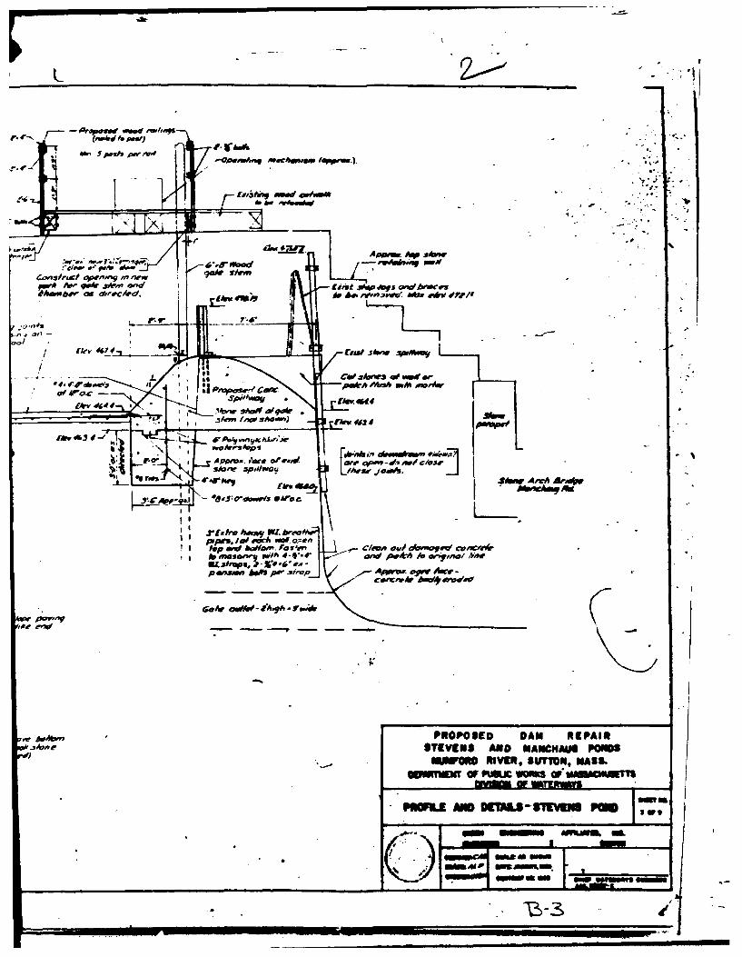
No data on the design of the original nineteenth century dam appearsto exist. The 1960 reconstruction of the dam was designed byGreen Affiliates,. Inc. of Boston, Massachusetts. Copies of drawingsshowing the proposed reconstruction are included in Appendix B.
2.2 Construction Data
No records or correspondence have been found regarding constructiondata, with the exception of an inspection report which states thatthe damn was revamped in 1960.
2.3 Operation Data
No engineering operational data were disclosed.
2.4 Evaluation of Data
a. Availability. There was limited engineering data available.The basis of the evaluation presented in this report is principallythe visual observations of the inspection team.
b Adequacy. The lack of in-depth engineering data did not allowJfor a definitive review. Therefore, the adequacy of this dam could notbe assessed from the standpoint of reviewing design and constructiondata, but is based primarily on visual inspection, past performancejhistory and sound engineering judgment.
C. Validity. Not applicable.
I7

g. Dam
(1) Type - Composite-earth embankment over stone masonry
(2) Length - 330 ft.
(3) Height - 28 ft.
(4) Top Width - 36 ft.
(5) Side Slopes - Upstream-stepped stone, slope unknownDownstream - earth, 2 horizontal to I vertical
(6) Zoning - Unknown
(7) Impervious Core - Unknown
(8) Cutoff - Unknown
(9) Grout curtain - Unknown
h. Diversion and Regulating Tunnel - Not applicable
i. Spillway
(1) Type - Concrete box culvert
(2) Length of weir - 10 ft.
(3) Crest elevation with stoplog - 518.3,without stoplog - 515.9
(4) Gates - None
(5) U/S Channel - 10 ft. long x 10 ft. wide stone app . ch
(6) D/S Channel - Natural Channel
(7) General - Box culvert is 9.35 ft. high x 10 ft. wide
J. Regulating Outlets
(1) Invert - 503.7
(2) Size - 2 ft. x 2 ft. upstream transitions to 2 ft. wide x 3 ft.high downstream
(3) Description - Stone box upstream transitions to concrete
box downstream
(4) Control Mechanism - Hand operated sluicegate.
6 I- - -- ~ ___ ____ ____ _ __

c. Elevation (ft. N.G.V.D.)
(1) Streambed at toe of dam - 498.5
(2) Bottom of cutoff - unknown
(3) Maximum tailwater - unknown
(4) Normal pool - 515.9
(5) Full flood control pool - Not applicable
(6) Spillway crest - 515.9
(7) Design surcharge (Original Design) - Unknown
(8) Top of dam - 526.75
(9) Test flood surcharge - 528.7
d. Reservoir (Length in feet)
(i) Normal pool - 8,300
(2) Flood control pool - Not applicable
(5) Spillway crest pool - 8,300
(4) Top of dam - 8,900
(5) Test flood pool - 8,900
e. Storage (acre-feet)
(1) Normal pool - 2,500
(2) Flood control pool - Not applicable
(3) Spillway crest pool - 2,500
(4) Top of dam - 6,850
(5) Test flood pool - 7,750
f. Reservoir Surface (acres)
J (1) Normal pool - 349
(2) Flood-control pool - Not applicable
(3) Spillway crest - 349
1 (4) Top of dam - 437
(5) Test flood pool - 473

1,m
1.3 Pertinent Data
a. Drainage Area. The drainage area contributing to Manchaug
Pond is situated at the head waters of an unnamed stream which is a
tributary of the Mumford River. The drainage area encompasses a
total of about 6.58 sq. mi. (4,212 acres), of which 349 acres are
occupied by the reservoir. The longest circuitous waterway course
leading to the dam is about 4.0 miles long with an elevation
difference of about 158 ft., or at a slope of about 29 ft./mi.
The drainage area has a length of about 3.2 miles and an average width
of about 2.1 miles. The basin consists of both open fields and
forested areas and is sparsely populated. Most of the population is
concentrated along the shores of the pond. There are no other
significant bodies of water in the drainage area.
b. Discharge at Damsite
(1) Outlet Works Conduit. Low level discharge from Manchaug Pondis provided for by means of a stone box conduit that is 2 ft. squarewhich transitions to a 2 ft. wide by 3 ft. high concrete conduit asit passes through the dam. The outlet of the conduit has an invertelevation of approximately 503.7 ft. The conduit would be capableof discharging about 100 cfs when the gate is wide open and the pondwater surface was at the top of dam, elevation 526.75.
(2) Maximum Known Flood at Damsite. No records are available offlood inflows into Manchaug Pond, nor of spillway releases and surchargeheads during such inflows.
(3) Ungated Spillay Capacity at Top of Dam. The total spillwaycapacity at top of dam without the stoplog in place is about 880 cfsat elevation 526.75 ft. With the 2.4 ft. high stoplog in place thespillway capacity would be reduced to about 790 cfs when the water surfacewas at top of dam elevation 526.75.
(4) Ungated Spillway Capacity at Test Flood Elevation. The ungated
spillway capacity is 1,100 cfs at test flood elevation 528.7 ft.
(5) Gated Spillway Capacity at Normal Pool Elevation. Not Applicable
(6) Gated Spillway Capacity at Test Flood Elevation. Not applicable
(7) Total Spillway Capacity at Test Flood Elevation. The totalspillway capacity at the test flood elevation is the same as (4)above, 1,100 cfs at elevation 528.7.
(8) Total Project Discharge at Top of Dam. With the stoplog removedand the low level discharge open the total project discharge is about980 cfs at top of dam, elevation 526.75 ft.
(9) Total Project Discharge at Test Flood Elevation. The totalproject discharge at test flood elevation, 528.7 ft. is about 3,400 cfs.
4f- --- ii

d. Hazard Classification. A breach failure of Manchaug Pond Damwould release water down an unnamed brook to Stevens Pond and thence tothe Mumford River. It is estimated that in the initial impact areaflooding would occur and that the Stevens Pond Dam and a dam inManchaug Village would be overtopped. It is also estimated that atleast ten houses, a mill complex, a fire station, and a library wouldbe flooded by depths of water ranging from 3 to 6 ft. In the village,the post office and another building would probably sustain minorflooding as would three or four camp sites located on Stevens Pond.Three roadways in the initial impact area would also sustain flooding.No significant flooding is anticipated when the spillway is flowingfull. In accordance with the Recommended Guidelines for SafetyInspection of Dams, Manchaug Pond Dam has therefore been classified ashaving a high hazard potential, since failure may cause seriousdamage to more than a small number of habitable structures and extensivecommunity and industrial economic loss, with the potential for theloss of more than a few lives.
e. Ownership. Manchaug Pond Dam is owned by the Mumford RiverReservoir Association, c/o Mr. Joseph Rosol, ATF Davidson Co.,Main St. Whitinsville, Mass. 01588. Telephone: 617-234-7451.
f. Operator. Mr. Joseph Rosol, c/o ATF Davidson Co., Main St.Whitinsville, Mass. 01588. Telephone: 617-234-7451.
g. Purpose of Dam. The dam impounds a reservoir used forrecreational purposes. Also, the dam still serves its original purposeof supplying the water needs of mills located downstream on the MumfordRiver.
h. Design and Construction History. It is not known by whom theoriginal dam was designed and constructed. It is believed the originaldam was built in 1836 to meet the water demands of mills locateddownstream on the Mumford River. The original dam was reconstructed in1960. At that time the dam was raised by about 4 ft. and widened by about8 ft. A 2 horizontal to 1 vertical earth embankment was added on thedownstream side of the dam. A new spillway was constructed duringthe same period and the low level outlet conduit was extended.
The work performed in 1960 was initiated by the MassachusettsDepartment of Public Works, Division of Waterways, as a flood controlmeasure. The design for the reconstruction of the dam was performed byGreen Engineering Affilates, Inc. of Boston, Massachusetts. Since 1960the chainlink fences have been placed around both the spillway stoplogstructure and the low level outlet control structure.
i. Normal Operating Procedures. No written operating proceduresfor the dam were disclosed. According to the owner's representative,the low level outlet sluice gate is operated from time to time and thereservoir is drawn down in the fall in anticipation of spring runoff and for
the benefit of property owners located along the rim of the reservoir.
[• I3

The downstream face of the original dam was also of stone construction,but it was completely covered during the reconstruction. The new2 horizontal to 1 vertical downstream slope is grass covered.
The embankment also serves to support Torrey Road which is locatedalong the crest for the entire length of the dam. The profile of theroadway is a sagging vertical curve as it crosses the dam, with itslow point located near midpoint of the dam directly above theconcrete box culvert which serves as the spillway for the facility.The dam has a crest width of about 36 ft. The crest is paved with abituminous material and bituminous berms are constructed along theedge of the roadway.
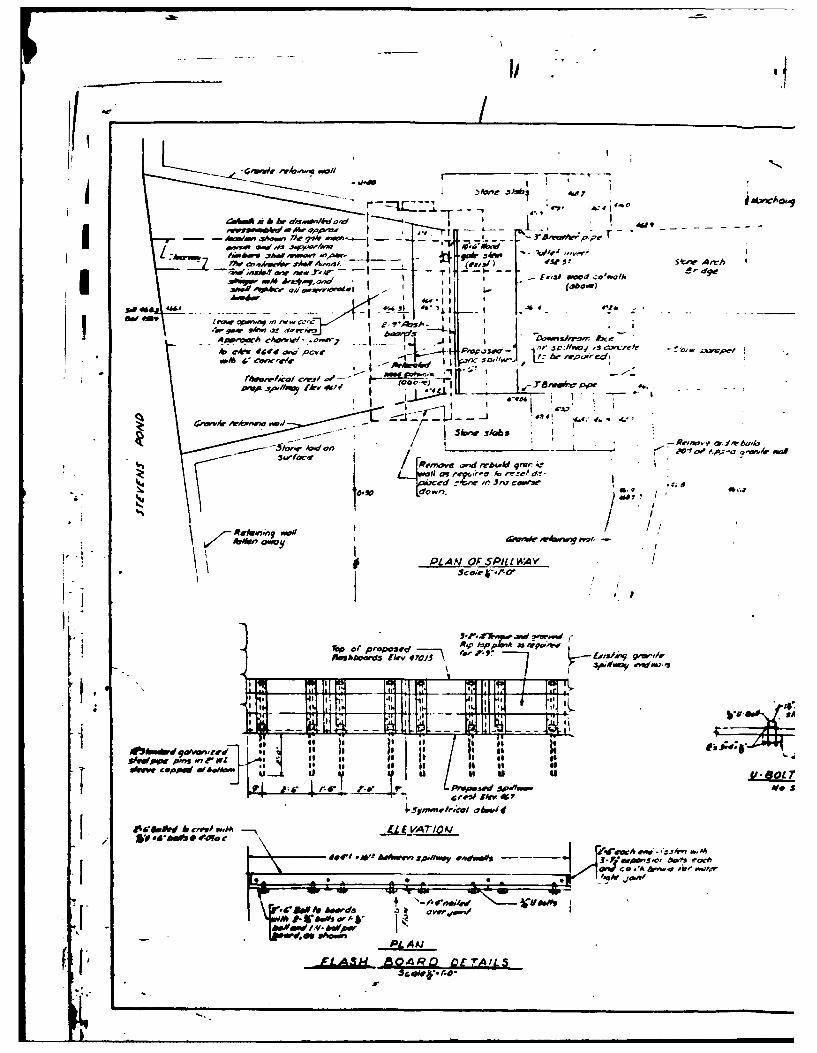
(2) Spillway. The spillway for Manchaug Pond Dam is located nearmidpoint of the dam. It is a concrete box culvert about 97 ft. long.At its entrance the spillway culvert is 9.35 ft. high and has a crestlength of 10 ft. As the culvert passes under the crest of the dam,its roof serves to support Torrey Road. The roof of the culvert is exposedalong the downstream slope of the dam.A plan showing the spillway inplan and profile views can be found in Appendix B.
The approach channel to the spillway culvert is formed by the remainsof the original dam and is about 10 ft. long. A stoplog facility islocated in the approach channel about 5 ft. upstream from the spillwayculvert entrance. The facility has provisions for a 2.4 ft. high stoplog.A vertical steel rod extends from the stoplog for removal purposes.A small steel access bridge spans the approach channel and stoplogstructure, the access bridge is enclosed by a chainlink fence whichis gated and locked.
(3) Low Level Outlet. The low level outlet for Manchaug Pond Dam islocated about 80 ft. from the right abutment of the dam. The outlet isa stone box conduit about 45 ft. long which transitions to a concretebox conduit about 60 ft. long. The stone box conduit is 2 ft. squareand is part of the original dam. The concrete box conduit is 2 ft. wideby 3 ft. high and was added to the facility when the dam was reconstructedin 1960. The control mechanism for the low level outlet is a handoperated sluice gate located at the inlet end of the conduit. A smallsteel platform and chainlink fence surround the control mechanism.The low level conduit outlets at the toe of the dam into a stone linedchannel which leads to the spillway discharge channel about 120 ft.below the dam.
(c) Size Classification. Manchaug Pond Dam has a hydraulic heightof about 28 ft. above downstream river level, and impounds a normalstorage of about 2,500 acre-ft. to spillway crest level and a maximumof about 6,850 acre-ft to top of dam. In accordance with the size andcapacity criteria given in Recommended Guidelines for Safety Inspectionof Dams, the project falls into the 'intermediate category on the basisof height and capacity and is therefore clAssified accordingly.
2
PHASE I INSPECTION REPORT
MANCHAUG POND MA 00955
SECTION I - PROJECT INFORMATION
1.1 General
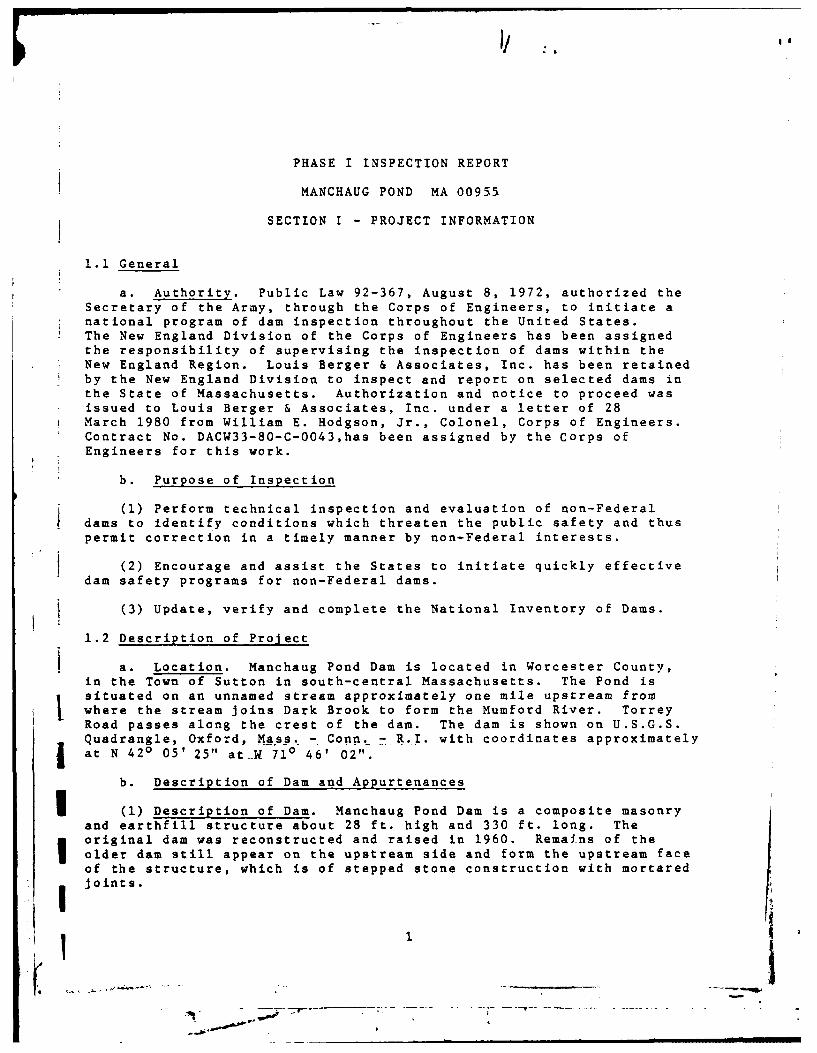
a. Authority. Public Law 92-367, August 8, 1972, authorized theSecretary of the Army, through the Corps of Engineers, to initiate anational program of dam inspection throughout the United States.The New England Division of the Corps of Engineers has been assignedthe responsibility of supervising the inspection of dams within theNew England Region. Louis Berger & Associates, Inc. has been retainedby the New England Division to inspect and report on selected dams inthe State of Massachusetts. Authorization and notice to proceed wasissued to Louis Berger & Associates, Inc. under a letter of 28March 1980 from William E. Hodgson, Jr., Colonel, Corps of Engineers.Contract No. DACW33-80-C-0043,has been assigned by the Corps ofEngineers for this work.
b. Purpose of Inspection
(l) Perform technical inspection and evaluation of non-Federaldams to identify conditions which threaten the public safety and thuspermit correction in a timely manner by non-Federal interests.
(2) Encourage and assist the States to initiate quickly effectivedam safety programs for non-Federal dams.
(3) Update, verify and complete the National Inventory of Dams.
1.2 Description of Project
a. Location. Manchaug Pond Dam is located in Worcester County,in the Town of Sutton in south-central Massachusetts. The Pond issituated on an unnamed stream approximately one mile upstream fromwhere the stream joins Dark Brook to form the Mumford River. TorreyRoad passes along the crest of the dam. The dam is shown on U.S.G.S.Quadrangle, Oxford, Ma.ss. - Conn. - R.I. with coordinates approximatelyat N 420 05' 25" at__ 710 46' 02".
b. Description of Dam and Appurtenances
(1) Description of Dam. Manchaug Pond Dam is a composite masonryand earthfill structure about 28 ft. high and 330 ft. long. Theoriginal dam was reconstructed and raised in 1960. Remains of theolder dam still appear on the upstream side and form the upstream faceof the structure, which is of stepped stone construction with mortaredjoints.
1i1t
III

171
i -/ ~MANCHAUG PONDDAM
* \\ -
%i ~* ->w Po n
r~ ,--~ - -
77
I cL
LOUISi.- ERER aAS IN C~ U.SAAMY NG NR DI.EEGLD
N NATIONAL PROGRAM OF INSPECTION OF NON-FED. DAMS
MANCHAUG POND DAMAI OXFORD QUADRANGLE
I II SCALE 124000L ATE=

MANCHAJG POND DAM
j OVERVIEW OF DAM
Iv

A triangular incremental unitgraph was assumed for the inflowhydrograph using a computed lag time of 5.45 hours to derive a time-to-peak for the triangular hydrograph of 4.88 hours (see computationson Sheets D-8 and D-9, Appendix D), indicating a peak inflow ofabout 9,700 cfs or a CSM value of about 1,470.
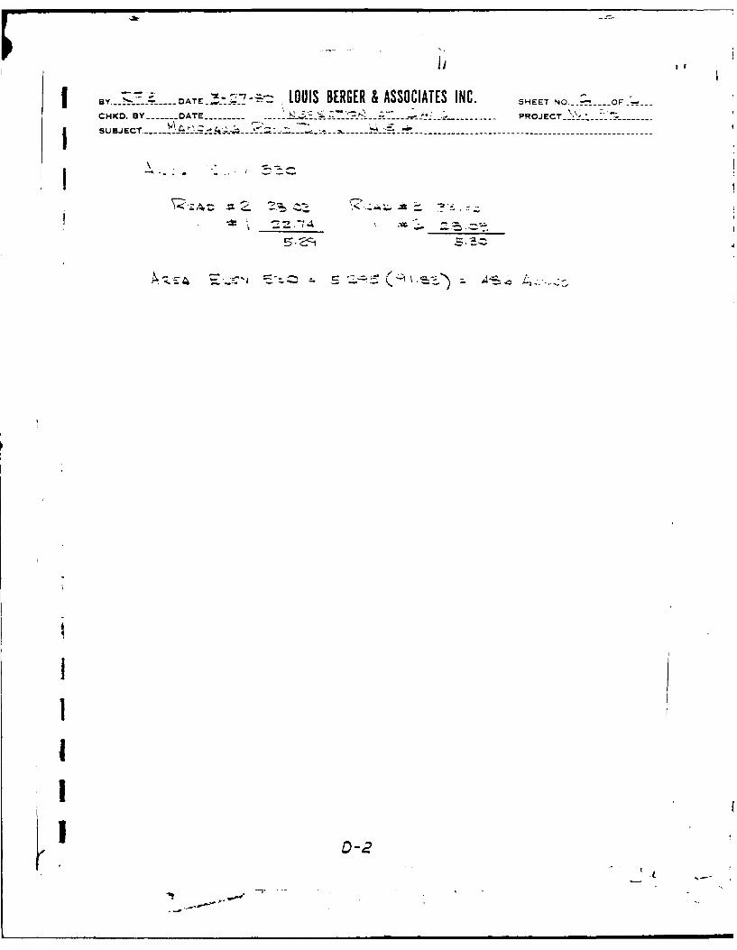
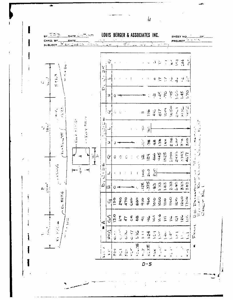
For determining surcharge areas and surcharge capacities planimeteredareas were taken from contours delineated on U.S.G.S. 1:24,000 quadranglesheets. Discharge tables and 7urves for the spillway and for over thetop of the dam are shown on Sheets D-5 thru D-7, Appendix D. Thedischarge curve has been computed assuming no stoplog in place.Also, it was assumed that there was no flow through the low leveloutlet during the test flood.
Flood routings were performed for both the test flood and a PMF.Graphical solutions were used for routing the floods through thereservoir and are shown on Sheets D-12 and D-13, Appendix D.The results are summarized below.
Maximum Maximum Head RoutedFlood Test Flood Res. El. Over Dam Test FloodMagnitude Inflow (cfs) (ft. NGVD) (ft.) Outflow (cfs)
PMF 9,700 528.7 2.0 3,400(Test Flood)
PMF 4,850 523.4 None 500
From the above table, it can be seen that the project will not passthe routed test flood outflow without overtopping the dam by abouttwo feet. The project, however, can handle about 26 percent of therouted test flood without overtopping the dam.
5.5 Dam Failure Analysis
A breach owing to structural failure of the dam by piping or sloughingis a possibility. For this analysis a breach was assumed to occurwith the water level at top of dam. The "rule of thumb" method suggestedin the NED March 1978 Guidance Report was used for the breach analysis.With a breach width of 40 percent of the dam length at mid-heightequal to about 96 ft., an outflow of about 25,000 cfs, which includes880 cfs from the spillway, would be realized, (see Sheets D-14 thruD-19, Appendix D).
About 1,000 ft. below Manchaug Pond Dam is located Stevens Pond Dam.It is estimated that the breach discharge would overtop the StevensPond Dam as the water would rise about 7.5 ft. higher than that stagedue only to the spillway discharge. However, an inspection of theshoreline of Stevens Pond indicates that only three or four campslocated along the rim of the pond would be affected by this high waterand that the extent of flooding would only be about 1 or 2 ft. Noflooding would occur in this area due to the spillway discharge alone.
13
I. .n.u :nn. * l n i i mn
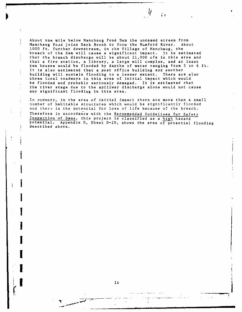
About one mile below Manchaug Pond Dam the unnamed stream fromManchaug Pond joins Dark Brook to form the Mumford River. About1000 ft. further downstream, in the Village of Manchaug, thebreach of the dam will cause a significant impact. It is estimatedthat the breach discharge will be about 21,000 cfs in this area andthat a fire station, a library, a large mill complex, and at leastten houses would be flooded by depths of water ranging from 3 to 6 ft.It is also estimated that a post office building and anotherbuilding will sustain flooding to a lesser extent. There are alsothree local roadways in this area of initial impact which wouldbe flooded and probably seriously damaged. It is estimated thatthe river stage due to the spillway discharge alone would not causeany significant flooding in this area.
In summary, in the area of initial impact there are more than a smallnumber of habitable structures which would be significantly floodedand there is the potential for loss of life because of the breach.Therefore in accordance with the Recommended Guidelines for SafetyInspection of Dams, this project is classified as a high hazardpotential. Appendix D, Sheet D-20, shows the area of potential floodingdescribed above.
1IIIIIII
I - m m na m m I l llm mn

SECTION 6 - EVALUATION OF STRUCTURAL STABILITY
6.1 Visual Observations
The Manchaug Dam is in good condition as revealed by the fieldinspections of April 15 and May 20, 1980. However, there are afew items of a remedial nature which were observed and which requiretreatment as outlined in section 7 of this report. The items requiringremedial treatment are the minor spalling of the mortared joints inthe upstream masonry rubble wall, the minor seepage entering throughthe right side of the inlet to the spillway concrete outlet structurewhere it intersects the rubble masonry retaining wall and the needto monitor seepage at the corrugated metal pipe adjacent to the leftside of the spillway outlet structure at its downstream end.
6.2 Design and Construction Data
A general layout plan and typical cross-sections of the Manchaug PondDam prepared by Green Engineering Affiliates, Inc. of Boston, Massachusettsis contained in the appendix. The dam was modified in 1960. The damoriginally consisted of an earth filled section retained by masonryrubble gravity walls. The 1960 modifications are described below.
6.3 Post-Construction Changes
Major modifications were made to the embankment and spillway in1960. These modifications were as follows:
1) The crest elevation was raised about 4 ft.
2) The crest was widened by approximately 8 ft. and compactedearth embankment having a slope of 2 horizontal to 1 verticalwas placed over the downstream rubble masonry wall. TheI parapet portion of the downstream rubble masonry wall was removed.
3) A new concrete spillway was constructed to replace the previousspillway which was removed.
Further details of these major modifications are shown on the designdrawings in Appendix B.
6.4 Seismic Stability
The dam is located in Seismic Zone #2 and in accordance with recommended
Phase I guidelines does not warrant seismic analysis.
15

SECTION 7
ASSESSMENT, RECOMMENDATIONS AND REMEDIAL MEASURES
7.1 Dam Assessment
a. Condition. On the basis of the Phase I visual examination,Manchaug Pond Dam is judged to be in good physical condition, butbecause of the inadequate spillway discharge capacity it is rated asin fair condition. A further investigation should be carried out andsome remedial work is needed. The major concern revealed by the PhaseI investigation is that the spillway will only pass 26 percent of the
* routed test flood outflow.
b. Adequacy of Information The lack of in-depth enginering data* did not allow for a definitive review. Therefore, the adequacy of
this dam could not be assessed from the standpoint of reviewingdesign and construction data, but is based primarily on visualinspection, past performance history and sound engineering judgement.
*C. Urgency The recommendations and remedial measures enumeratedbelow should be implemented by the owner within one year afterLreceipt of this Phase I Inspection Report.
7.2 Recommendations
I It is recommended that the owner, the Mumford River Association, shouldretain the services of a registered professional engineer experiencedin the design of dams to make further investigations of the following,I and should implement the results:
(1) Perform a detailed hydraulic and hydrologic analysis to furtherI assess the need for and means to increase theproject discharge capacity.
(2) Inspect the inside of the box culvert spillway during a periodTof low flow or no flow conditions and determine whether repairs areI needed.
I 7.3 Remedial Measures(a) Operating and Maintenance Procedures
j (1) Repair minor spalling of the mortared joints of the upstreammasonry rubble wall by repainting with mortar.
(2) Repair voids in the rubble masonry wall at the spillwayI approach channel on the right side by repointing with mortar.
1 16

(3) Monitor seepage emanating from the 6 in. diameter asphalt
coated corrugated metal pipe at the toe of the dam and to the left
of the spillway outlet to ascertain any changes in clarity and
quantity of flow.
(4) Develop an "Emergency Action Plan" that will include an
effective preplanned downstream warning system, locations of emergency
equipment, materials and manpower, authorities to contact and potential
areas thit require evacuation. The plan will also include round-
the-clock monitoring of the project during periods of heavy precipitation.
(5) Continue to conduct annual technical inspections of the
dam and its appurtenant structures.
(6) Implement a regular periodic maintenance program.
7.4 Alternatives
There are no feasible alternatives to the above recommendations.
17
17
ii

Appendix A
Inspection Checklist
t
IIII
1: 13II,

VISUAL INSPECTION CHECKLISTPARTY ORGANIZATION
PROJECT Mancha,,g Pone n.m DATE 15 April and 20 May 1980
OWNER Mumford River Reservoir TIME qtja AM
15 Apr Clear/CoolWEATHER20 May C'oar/Croo
W.S. ELEV. 5 4U.S. NA DN.S.
INSPECTION PARTYPARTY: A/E Representatives Owner's Representatives
1. Peter R- D)ynn 6. ToAph Ronnl
2. Paquap C _tc-t-1 7. crrl leran.
3. Roaer F. Rprry 8. Delwyn K. arnes
4. (o1 off_.. 9.
5 " William - 7nin- 10.
PROJECT FEATURE INSPECTED BY REMARKS
1
9.
' 10.
LBA - Louis Berger & Associates, Inc.
Ii~ ~ Z -. Go'erldber,ons &pAsocate ,=T nc.~ ~ i T,
I .A-
I Be.e &Asoiaes Ic

PERIODIC INSPECTION CHECKLIST
PROJECT Manchaug Pond Dam DATE 20 May 1980
PROJECT FEATURE Dam Embankment NAME_______________
DISCIPLINE Soils/Geology NAME William S. Zoino
AREA EVALUATED CONDITIONS
DAM EMBANKMENT
Crest Elevation 526.75
Current Pool Elevation Not Recorded
Maximum Impoundment to Date Unknown
Surface Cracks None
Pavement Condition Good-Minor sporadic cracking inAsphalt paving
Movement or Settlement of Crest Negligible - about " between embankmentand outlet structure
Lateral Movement None
Vertical Alginment Good
' Horizontal Alignment Good
Condition at Abutment and at Good
Concrete Structures
Indications of Movement of GoStructural Items on Slopes Go
Trespassing on Slopes Negligible
Sloughing or Erosion of Slopes None
or Abutments
Rock Slope Protection - None
Riprap Failures
Unusual Movement or Cracking None
at or near Toes
Unusual Embankment orDownstream Seepage About 1 GPM clear water from toe
drain outletPiping or Boils
Foundation Drainage Features None
Too Drains Good
Instrumentation System N/A
A-2
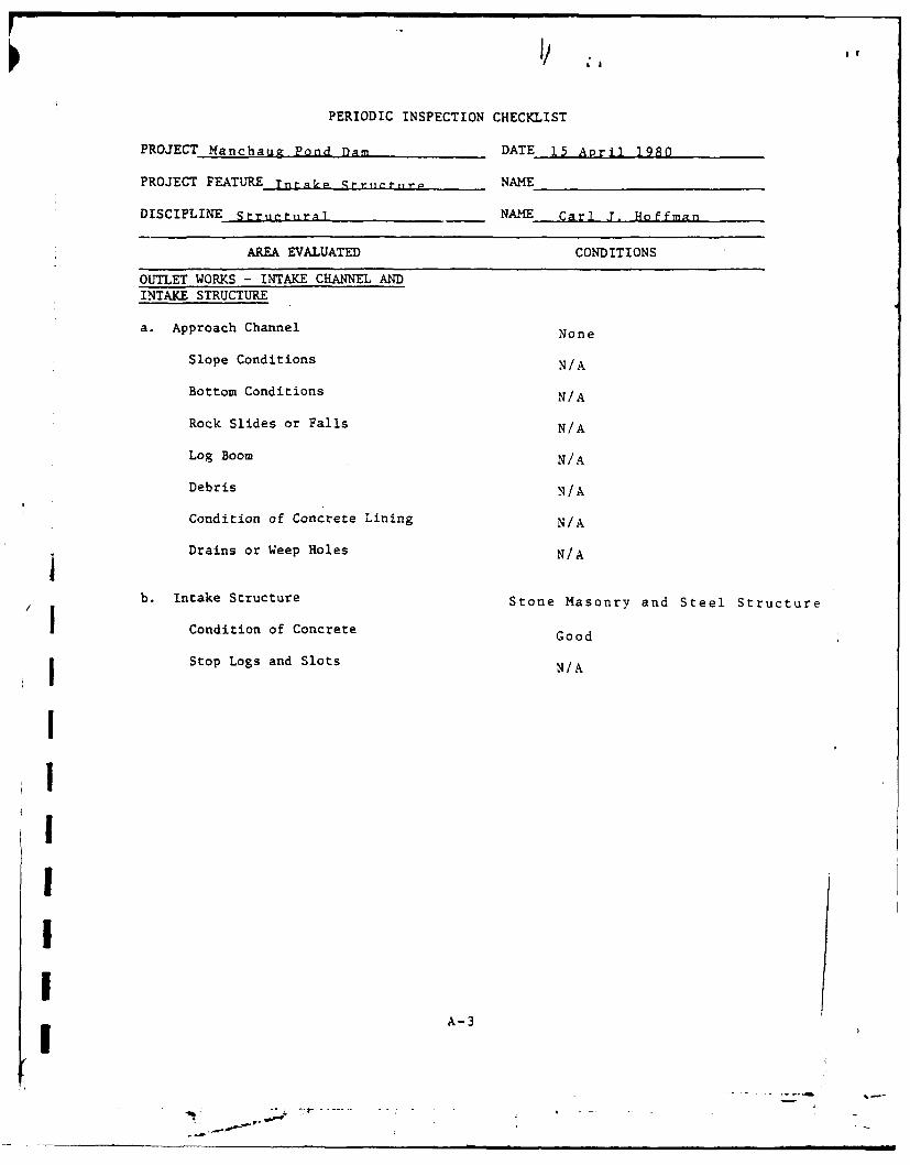
PERIODIC INSPECTION CHECKLIST
PROJECT Manchaug Pond Dam DATE 15 April 1980
PROJECT FEATURE Tntkp qt-rjnt,r NAME
DISCIPLINE Struntural NAME Carl J. Hoffman
AREA EVALUATED CONDITIONS
OUTLET WORKS - INTAKE CHANNEL ANDINTAKE STRUCTURE
a. Approach Channel None
Slope Conditions N/A
Bottom Conditions N/A
Rock Slides or Falls N/A
Log Boom N/A
Debris N/A
Condition of Concrete Lining N/A
Drains or Weep Holes N/A
b. Intake Structure Stone Masonry and Steel Structure
Condition of Concrete Good
I Stop Logs and Slots N/A
IIIIIIi A-3

PERIODIC INSPECTION CHECKLIST
PROJECT Manchau2 Pond Dam DATE 15 April 1980
PROJECT FEATURE-Conduit NAME
DISCIPLINE Structures NAME Carl J. Hoffman
AREA EVALUATED CONDITIONS
OUTLET WORKS - TRANSITION AND CONDUIT
General Condition of Concrete Good
Rust or Staining on Concrete None
Spalling Minor spalling at outlet end
Erosion or Cavitation None visible
Cracking None visible
Alignment of Monoliths N/A
Alignment of Joints N/A
Numbering of Monoliths N/Ai
I
IIII!II A-4
ri

L 'I
PERIODIC INSPECTION CHECKLIST
PROJECT Manrhaug Pond Dam DATE 15 April 1980
PROJECT FEATURE _p________ NAME
DISCIPLINE Hydraulics/Strurtures NAME Carl J. Hoffman
AREA EVALUATED CONDITIONS
OUTLET WORKS - SPILLWAY WEIR, APPROACHAND DISCHARGE CHANNELS
a. Approach Channel Stone Masonry Channel
Fair - Minor spalling of mortar and someGeneral Condition leakage through right wall
Loose Rock Overhanging Channel None
Trees Overhanging Channel None
Floor of Approach Channel None Visible
b. Weir and Training Walls
General Condition of Concrete Good*
I Rust or Staining None
Spalling None
I Any Visible Reinforcing None
i Any Seepage or Efflorescence None Visible
Drain Holes None Visible
Ic. Discharge Channel
General Condition Good
1 Loose Rock Overhanging Channel None
Trees Overhanging Channel None
Floor of Channel Good
Other Obstructions None
I * Spillway is a Box Culvert which was not observed from the interior
ArI

PERIODIC INSPECTION CHECKLIST
PROJECT: Manchaug Pond Damn DATE: 15 April 1980
AREA EVALUATED CONDITIONS
Dike Embankment N.A.
Outlet Works - Control Tower N.A.
Outlet Works - Outlet Structure and NAOutlet Channel ~.
Outlet Works - Service Bridge N.A.
A-

Ii If
Appendix B
Engineering Data
I
I
11
I
I
I
I I,

_! - IbY -;- A.--j _ _ _ _ - _ _
;Tkd-
5*m &x CC4~
~I A'."
7.~~' at :
JW-I
I a _;3..f
SW., e1.;,
a e ;c &)11jFo
Al Orc* -CE
S~r~.e(f~a ~ frill!E
1.3O~f 4,v4Tae ', i~ g5
soa Ix --d!.
5~ co
Co vdp, o of &.W, - C'ntj -Wi. . 0 r
-96 - a" 80 &WOW
90-40 L' ~40
J1 W W, ojIW c1 ny ,*c I.* &a w A

--- --- --
I.i i I
_ i t
IiIq
*a lj.i
IW I I
"
-ii
-1 I ' , ,I
4 • j "
1I !
I
r :--:

I , " II
h I
1~ii j iI! j' I
. ......... . .. . . . ,1i
! .'" , / '
l. I
. 4 .., .
4 .. " 4..I
J K
-- i Ii- - -- I I ' I

C 'c
- &MkNXAU C~oVCa'u COME .57VE dUTTERC44W4 DETAIL Ab to feit
-rj
~~r~4f 1 ON" qg.,d AWi
$&.r 4*AM'm~,
rrpx44sn. suummoze AspAAcUo.Am
inAf mI( W~1~n

9w o 5. ZCoi~um*m
1I-6 -- - - _~w fto
YICAL ECION TOP4'EY ROAO( ~4
-2k ro

. . 0i
L)FR AllER p,W9" SUTTON MASS.~
8.M~f OFii P .'d WORKS OF e eA MMT
PROPOSE DAM T REAI
RIVER." SSam"N MAS.D~~TM~~ff &PRUCwow. P ASIJE

[7~t
I
Ia--~-----,
- -. - ~~~~1 '
1. Lif
1.S '.1-a
~.
I I-z I
I I -
twi~y b..d-'~ d -
-a H4 -i--a H
a.- ~ ,.~ p. ~ L.- - - ____
P~Ot L4r* 7r~WPEv PB
V.',s/.Ma' J.4O
am
am
I' I
'K
~ ~ ~
- '-S.- '4.r..j
-.1 q'7~(* 44eKfe *2
- -:1
~1

&OmPI.t
Of~~ ~ ~ -pi-'g0*dome PhZ W
'too
-m am
'c ~ --I '^ -owo 0
1111 11 5 - Iv
Aw t'gf/ -- i..t!d
AMP -- J _ " v ___ Y AP
AAw
a/ IbP4AmIP
At PfaOE toM AMEPAIR
nd .*wCone AE.,E. tToEN AND MAO All p0AoN
in 6wnrsnoe MASS. "
~a -
CO-P
~ m g~ ~ jot
-- - - - -Tomd..d sox-

- ,*~ : 9 A4JCNAU4 PV.O
%&wee.,
*j0rtrs to* sr4 0.00 rI5 rO 40: A J,,o7
lr,,yA AFJ a,' 4fm l
I ~ ' -is' qp m c AU.O.wil d~~
jar ?A -d" 41 ''
7.Mr A&&'
~ ' -,rren54 53
of_ -,c av ie8 '
&P 4;7 S ra.& J',
t95EtV 9 ao. -,-
PTdM~/A / '. 3wwI
- -~ pro
Z. iJO f JI- LISi 4- 44 M
W~-~o# AS.
L/Ilse e1CI~/.,VPR LLCAhJO~LWII ,
______AND~~~~~~~~A S7A0R .j I7 5XA.C4
4.~w Jhv~u? R~ ~ AmMI'Aq
Awew______ _______________ 1'Ns
-. 4 ' --
r-
-Lli~ owede med Fsman9
1, -OpAn AP.C WSA IllVW)
dozbe asor-'a.a~~w
I., -V&____97vAtr&k
Cav~pathC Airs*9 mNh awe
-------- 7,.'.~y f w s o- r~r W
rasc 4A4ash I~Ajuf
Poes I/e Jwor af '
toPp -t bamai". foAo"v~~ C/mud) ovi obmarow apncemk(
p.~swn hANe zfW.imp AA o- A we 9r 4e
tw ROPSED DAM REPAIRSTEVENS AND MANCNAJS 10100
MUoMo RIVER, SUTTN, MASS.
C )OPMA O~A--rn.K P=______

CO-40DI~d~ES 0/
AqOFO.'-. SPLWYfl6-m&~d -s ces~oed '
Ard ,# 0 11r, 1 Aw V,rqoM ~ ~ ~ ~ ~ ~ ~ ~ ~ ~ ~ r DD4ERA#r~ 1es crufd I,0 p
* o 9
A 05
1.9 0AD AW~sihV ensap'w scomq tool
049o 0.S 1ew 4
] CevC. channe! c .*oo,/
PROFILEI Or SPILL4 WA Y
Ahml ardW, AVI0
dAo=
/CAf by ~ 1~s~n1e~anW d*p fWIWI7

*fg WO hamTJr.o
I ~ ~ L~w ON kI MoMsLlgS br.V05d" 'r.. doo" SAo 00 a
f4."6e. ow dg(A SAM0te Pf &h/ww,, A£oV~meq______ I ad~~d --iro Awt and /t poid. cuo odo' *wv
___ -now diM.
__dwa as -~wn -, j i'
Jw odma.. .* Aa ZA~ Z' a-w s._ _ _ fr.4 aI#2
3 rl Vt MS POND
'3a
I -A
Am Af - lcsA1./w w gd
LI-BO~~Al a1Tl . ~-i.ife S ce b 4mSl W oodwU
E, W~~= 15 AA.inS
A*S PROPOED on-%AM REPfg AAIR/#'31wkw gaword R-STEVENS f AN &ACNI PONDS
MUMFOR R!VR SUTON MASSA645-~~~~~e d~TN FPUCwmsO ASAIJET
PLAN Aele DEALS-STVNSPN*"Y N O-- ads #17.
Am~~A *Ae..~
PROPS DA EPI
STIEIENSANDMANCAUG ONDVlI ~ t R!~fSTO.WS
ui~mO UM FMSAMET
(te .*.h I
m- -
e%'
I~~~~~~~~~f- su/1 ,2 ,-. ~ -- lA~~".-rAr
-~~f IV*1ftWWt~.I I .- fIwo ooA
A-_~ ""'d-~~~~~~~~ ~nw~ 0 -- - ,''L"' t'6 __
wal asrphc b*2 a!
pA2ce r Sw I d cw se
L.AM 0,SPL KAYo~/;-aoa'~v
*~~~~R topIdw.' ,Ole,~
I Pi .I
u lu
is qdr-rv /Fl m-w
OWSPAW* AP ,w/ Prom -L VA7-10 A
co "OA &r"w Are em*v
I'. h&eda~ z~ It
f ~ ~ ~ k If6A AbOa: 7ET'ALEO,
10

_A Urro-~4,p !Z foew~~.4re
N S4v/an bc 4p
-'b~ , O 'At ~.4_'ae Opt -9 4 Cr/"J
jent .,I
50. W4ii6
A- m I,
~ AS. De~crj Agef
I~ ~ /A~ OF DiL -JevN: P
~~GIm PA A sh- Pfohw )%d
Int fw7 .fpfweq Atm. and Pp. f 1 ' -MACEtuU Pbon
A!1Ia Lrw rv'-j'ew Jilt
ftC ole 5, I Jr... ofA aw' ww jew0"es..5~ * fleraE A £P -Bc' le hene :wu ~
454 Awe of or)Aej .ww/ - 4ma3 Z reWI3lf boo eA rww F I' NY&#*, P70 00d d*oc
C.4IS' aw fio
6 4 0 Cf
PROPO3ED DAN REPAIRSTEVENS AND MANCHAUG PONDS
IJMPORO RIVER. SUTTON. MASS.OLNATT OF PIUC 'WORS OF MAS&SMWJUTS
LOCATION PLANS AMD BORI DATA
in144if WgL.

P1-CO-I~ Pf-cO-f
0'" for
- 14 1.
dt~
00
A*~ ~ 14 sil-1 1 7 w 'u Ae cUI
SW-/c
sJC ,-.x' S' Cal - l
Jil 7,K oeO - Srfl (0-4 ~~f-P W A d7-~~~I~ y 1WM-dO %
AV- 4.f.ejcje -- 1.V 5.
10 i l ch £# *
___ 31mV o r. m
$ff 7 M 4r.5 oAVvr"Vo
A PamSlowAx arr r0m W*W -wv,?: Rr 1. , FM PdW. ;CI
S o.,/.e Fo Ajod,.
&orI~ a a n
-feu ?lt ~sdmv eom,'~Uck*' i.
£flrww U' p4wm jnd.,c2A4 6/vmi Aff" d"
1;.Fop-wOAWM A ", Jow ofe J4Oa
AmsOdw c~mfA,.dira avto f lla1

II
.' •~ '
,4
.. ... A -
, - i y..//_
. ,
t. ;,i
- ,- -.L
'7,
• -
- ._ _ .," I- o
'S- .i
4, *- '-
~~'-2:-- !
tN
-I
~c 7 'j'
. ... i i
L.. :l ' t or~ a."* '-:~ t saCr C 'cr 1 71.
ro. -] -. --', o,: Z, , ,-~1 c ~yil a: t ;d r k" 1a o ha
a core, at 1 en!,t r'u6'11 -d cl av bit t"'r ar_ n-) -1 '- -to v,- to ow10 t2' r1igIr_ ccnctruc' or'. T;s latt I'r Otm -, '1cal ir. 7tatc 7ons Pam. :t
is a s.71111 dn:, o!mchi-s a forre~r '.htin 7at =J backs -,n a s-all s c f
C 1'_ 7 revcr be, , uccd. i4. "- :,-,- -- t".._ ! 1 - a'(z oc'v 'Inrfctior in ti c dlhicrlu r
otle: -2 i an acs-tl!,ftic wal,_C. :;r cc 1, c a. uxc v~ W Lrr-c1 'Lo.;a~: ~:cs- nas Ycly .nit in z2 no value to thne -lauit o~
..c~ eurtl;. Jda !:ricvn, an Lac>:-Y )io: owno'L* I. - r 'lle~ ~T C an'.:timbc- a.C1 mood 'lour J'- Lm LvnfItc !-!.cc' :sih's -it each cnd and a dual
~tr'ctucoel'21;Cj -rith rack and -'iniou. I.-, l.crngtk, of tlosilwc is ~4-1 da c.:esto :Ierna.r-cnt' f1.asli W- c ii t ton of the pill-,:: T -C
-it1 :V- ""o;.:.,Ir cf Jr- titl aift'. the flo . eloc r L z .: C r nc C-i I~' - _ -i ' . nt it ma :c Id c i f 1 -4 tied to ruc a rlalor rzpai"
e; c~ic..." . rcpl nc' itIedt.Thrfc ti:u- baci. slone c,' the fda. inn- a
c-._- ;, - ic 1 olazm tIC! ;:.s di .s el er' tI. a b*rnkict of clayThsis to) :;:.I or*.~f mt:t~w- ic ':e irons: a=d 1 c.,-
"ito.1 ofmm lcvc n 1t xcsent 1'' s C;ntji. :i p --n.i to- a
tl.ie tr 1- .."-c irch b'' nwi
a f _,r'tci apprnoxaJr-- -dt( Lan , noct1avlu for thc aeC,,,
orrd if :o n .4& incc the
7.o
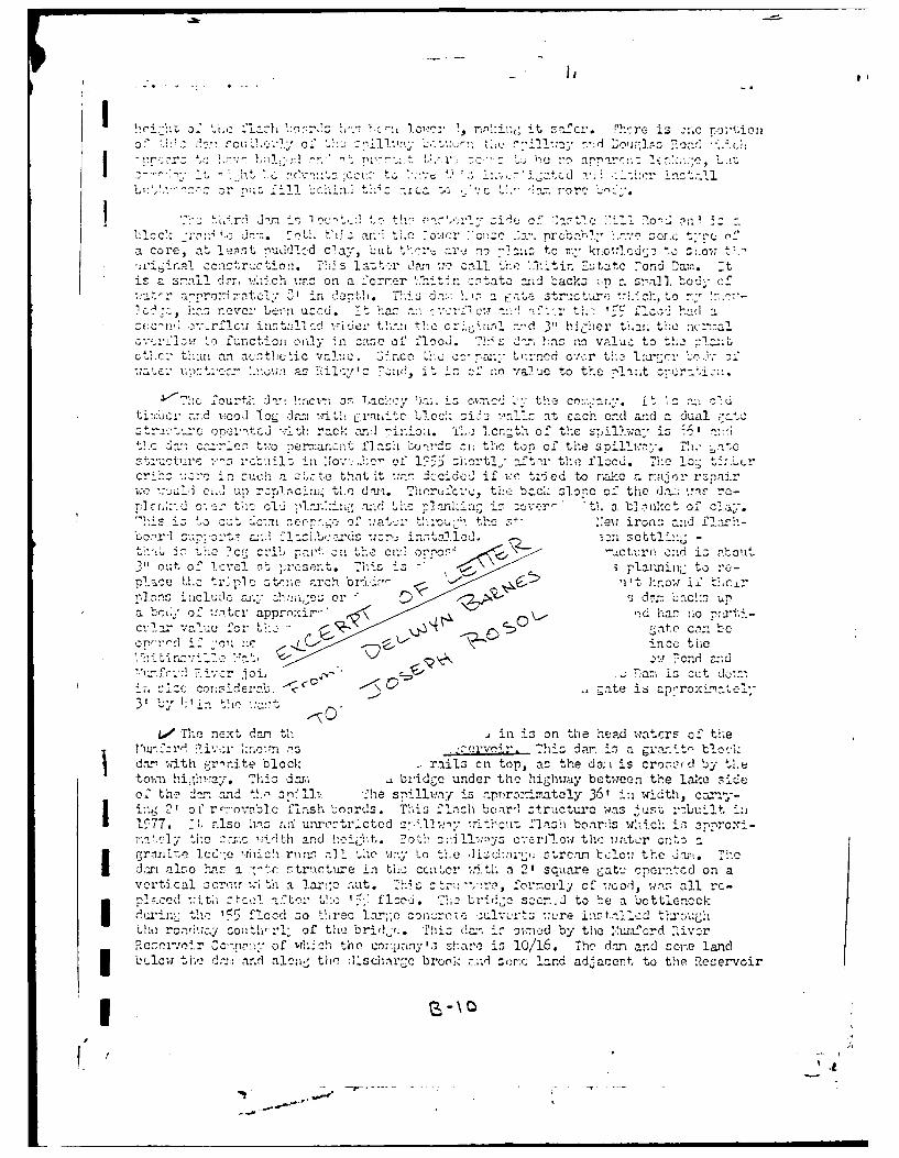
L. The next dan tE, in is on the P. d ,Yaters of th-e? afrr ivtr 1kncmn :75 c srvo ir Th~zs dam -:, a gr~"blnock
dw- with cr-rnite block -ails cn top, a.- the daui is croso-rd by tl~etotnhiTmam This dar., bridgec under the highw1ay between the lake 3icleo the2 d.= and , -.-s:T. 'he s-'41 lwn~y is rapnroinratelY 36' in widthi, c=orry-
' o r'-oviblo flash toords. This flash bcnr'- :structurc wsjr cbiti1 77 :- also Iriz ar unrostricted s.'A1iil -rit'-cuti flash boartis .ich is onroxi-
~nc id h ad high. Tat>sd Lo's c:orlowth': watcr Ornts ar w~ -hicli riirms :-11 ' th winy Lo tihe d~c~';strcau clo-. th art. T -e
Ju 1 alo h.ts a :-..c: !-tr!.iture -;n L11; I c *ntcr wth a 21 sGuare cato_ rperatcd on avctca 1 cr!o_ %-i th a 2.av,:c n-ut. Th stru 't!crc, formerly Cc mood mza al~l ro-
* .Ccd~ ..tk l ni :2110 Lh:, 1'5j flool. 71;o brie-: sa-cr.-d to hea lbottleneckc -11 n 1rnt ' flood :so thirec larTi;o conret ---itsmr instfallc-trc' g
Lorcnr -ay colit' rl of th.! briel,jr.. ThiL dan ir ownd by the ".wifcri ),ivorE csiorCO'n-.- of WhjTh thO COryanyVI'13 .I zha'.' is 10/116. Thc d.=- and sc-e landb,.lc-w ths': dm r.: a al n tliv dlschargec brook zoric 1--rlad ad-acent. to the !Rejervoir
IC

at tic far cnri of P f Rcr-.oav -xr o!wn"C-. 1believe, by ATF/Z-avidscon. f~ydir~c:-.kson oth'-r than .al zt hIv Lio :', . L'c~tinOf thetc dt C; -,1Of w.-4rr
wi., i 27 at fuli ,-cnj, Tw&J~.et !tiiO ju ~ ~tMi~~~cc-voir 11'-tL PI CMswC.ay iwhil -- cuLt: thep >cviroughly in I.-Of. Th i5 ca- sc -"-ty,1aftcr SC7ac otiv1y -was rrovell, to btlr.,: to thec town and at t~it tln-.- thocomipany reoainrcd tI.c colvert which loino t':e two bodies togtethEx and inotalledColCIecte t7Uan] r::ils ou the -, cul~vert. Mhe oInl ma-dintail the 0:1~~yso tl-O eo"and oll thne caucceway. The. dn1, ha.; bLCc fen:ccd o!,th dcwn -trca-.n face .nIth a
j chiain lial, fcnce enI thc g;ate zt, ,u!,c tr aind ovcrflow structurc havea alqo _Con
1,1Ct =nd final dan'. is thec IaevgRec-rVoir Corporation.T'i-ch inat rcont ~:a1T ) Of tw-o Mills - T''~vdo o'..nE; 5/6. The :'anchau.g Ron'~ervoir
D - is *a .3tcnloAc!: doi as Mroand hao a GLt. structurte -ith a 2' zq-1aLrn,-ate - the sano t:,,' -c of orcration .7ith a vctclscrcw and nitt. Tile sii
geh tho" ho~' top o' thec darm and her rernovablo flash boards. 71ho siliayis101' in .,-dth anl -is Practically 100' high TAndc~' flasil boArds 011" igh -1I
oem ~ 1h- orgn:ly c ranite blocke guiarl rails-, but. after th-e r' flrnod the asna-chucscttz :,eartmcnt of P-Ublie 1Mrks, T ivsic en of M..atez-rays, made ' a study of th.e
Stevens ~ ~ l Pon D.wih is .-,ust do-n stream fr:tm. tho "anchaug a ndwsdaaedurin6 the nleod. Tiioy decidedi to spend cor!7inderablu noney on the 'ench!%ug Rcs-ervoir lari so that i t iwould act as a feed control dwan and would thuo -rotect the3tevens1 Pond Darn inztead of :zpcr;ciin[r a large x,:oiant of moriey ca thec Steve~ns Fonl1 am mithout near ac beneficial recults. To do tothey rai..cd th1,e Jam's heightanid greitly rclinforced the don, by ad'iintg a lonig slop embanizerit two thle back. sianeof the? d-:.-. The to-mm hj.ivwy also cronsses tli;. d.en. At the same tine, thec State
r, buiJlt the Opillway and tho brd,-,e over thei :;:il*lvay -nd carrie:d tie,illrdowni to) the b;7dc: top of the dun a.il covered thcis oillway to this p.74int wreitdie!_chnrgecs into tuhe otre.am. Thi~r, is thteia: strcari which the gate st-ructurc zl::-char-g;s into. The -itc sti'ulcti~r, an-A the zr*illwaw. stracture have al:7z beerhage0over to steel alld fonced i by t,-he S e rvo-~r Coraiiy. The front face of thedoni above the oridinal gr,-niJte bloc% i-all is rip rep. The hib-hway erosnn thkedom is mintaiind by7 the toira alnd has concret-re and cnble tguard rails - alsoplaced b)y the town.
"lhe :!w L,,n Sho Tan, th -,wr :c, ,, Da a-nd the '-. Win E ita t c Poud Da;.arec nal ca in the Town of !orthbridg;c. Lackey Dzlm and aehu;'a e1 coate-d in the n *: of Sut ton andA the." -. fordic Reserveir Doai located inthe Townm of louqu'las. Portions of lacke.y rend are -in 'Sutton1 and Unrdoa.ndportions of M=aneug Pond ar. in S;utton and Dijlr~. Portioins oi th-3 :hi.,fcrdItiver backed up by the Power IHousp Dan. are in Northbridge andi Sutton. The othert..o are in ::ortlibrid.
The damsii hava been .-ell maintained yearly, keeping all brush and graqsmowzed andI doing all nccosnary peinti;hg and mazonry, repairingc strunturez, etc.
anece.ssary The annua& ispectionl uzcd to 1.e done by the 1,rcestcrI- Coun1ty.nginer. t snwhndd bI tl at 'oassachusetts. 1 4P havc al'.n-rs
beCen co'-.1fi metcd oin thc :rainten.ncu of all thes ns. The'.- u.rre viewed inoItail in 197), b:* -Z. T'r-s :f-,.r-oan of thie :rvel .s':surcncu li~pn e
vi.cd thcs' again in 1977. The damn are nw's oi".ne and regul,!atnd buy the*:iti!nsV1llc .- d Co':ziny w l~;ispucto ax:' aictw.3rc1u-- nz7
tionz. Zoetnedrii- citical pt-riods t*hcse;r inzeticns ara oftelicz than onc(ea day.
jThe ".inchaug :Thn .-mr built in 1 36 nd, revamped in 1960 and the I'umford Piyerdan ;.as built ia 105h. 'The Lackey i, rn'~e was built arciind the tinie of

I particularly the,, fi eec] of 19<Aci ehd 39 icc of rain ba!si oally ovocra Li-roe-dny ICl)th10:~h-2co 2'wU
MSt tr I'('tje i- A t r.:, z; e::v acl.cz7cl i n t!. pant air-a. :ru- l. 1muJI Ln rcp-isiga:,I :tvc very godu <rrte2:.t the roioforces lhthree tow.ns a. C 1tLV, v;:c iearsoiUv:;iir.
I The ':tkrfoard a.:d zchu (:-,z w-71. ;rL: as e Cawpcritcr - '.a:.: -?-,-a oe da; arid sold to to htia Ie ater Comipany) were bul t torc
water to rakc cure t..L-t thc ifrn crvixfl'211CS cmilng 5 ohires, a:< co-S sztsUPuly o'? wnter to on 'r- ruhu die r '.The aroiuit
ilarc nnof7 an- u-u not - io'.ly ' ca ol l wao z'*ylctLare nero -meno an ILrsevos e r oltvrte : i apn
t :ie 'land undo-m- tni( rzecrvoirs -::ain u:-- fr 2.o-ragc ni -t'i! rP0-L,7112ojci bt c1 adct: esauLonI'are 1,01-.-
12h-rcisa:. r ior -,ia -yu <gtwstto have, F'3(2 .Le Jltjtry to) ;_ai t for yo)u.
V c:traly-: "urs-

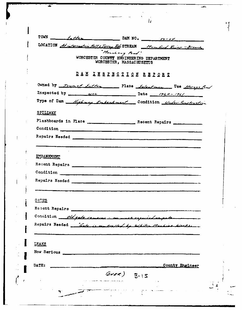
/V TOWNOR CITY.T, DECREE NO? LO _DM~
1 LOCATIONPnt'e w,4aaMne.Jmui C. Q. O~~~OESCRIPTION OF DAM 4umrro -r 1111RSPTIONlf aP RERQ
~~~:r "..d h ,FQC 4 Y4.I alpe -ai~a N.mt -hLS Xanc, u!) Po - -,4~- Lemt~i" ay otw5i eams,
I Thicimigas top 31 Width * ~-Dottom 4-d'. 70' Is Watershed CWUitiw d
* .k mailo trearm Slope i76 4-1 Percent In Forets
Len& ohf Spillway 5-43 67.t KindP of Sip Ab 7Size SofGets* 3x 3 F/ $5 74 No. of Acresin Watershed ~7 S-Yk Loc-stimof Gates 71. 1. 1 Reservoir C. c riI %Fleshboards ased Len&t of R.,senoir Z-7 Xar* A/.Wktb Fluabboardsor Gates 34 5 ~ Width
_ de~fmed byMax Flow Cu. Ft per Sec.C11111611ucted by Hesia or Flshboads-Low Water
~corgructe - - 4.~ - -High'-= - GENERAL P1EMARKS -_ -- GENERAL REMARKS
Owneitr: Mom~u ee o. o-e-~,
LailkaJ<e .'None *'4Trai 3037 1A,4F, V, /QP-d 2 ~
7-41 0.. .. w0a ce4c 1*a.r 3-2S-2 7 39 - &.A/.fArlvi 417-o-k -Iave PAm'na, C.0,A-0/i '' /nvpkcc/Cdv 19C . /3, .4c - ~
In5pec +'d: Sep*. 9, 19A4. Mao. ew /Y.A .o Juno~ -r, ~ It / v 3 / 40*A5Scez
-"en I /70?' 6 %.,A/cu.~~~~~~ Z4Z. /90. - e.- .. ~h~u,-R
A~ ~~~4 V'7 $:9/ .i-~~tC~I
I7BYv.1MO.ZI/A#7XJV7.I"
01

II
I ~ ~2c~jc ~A' ~ -\ , - •-
'K !
1 ' " ,-..,- ,
i ~
i
I~
I
-- ' 4 I -I II
TOWN _____ __DAM NO. .-.....
LOCATION ~ ~/ -- ~2~STREA -io'..c --
WORCESTER COUNTY ENGINEERING DEPARTMENT
WORCESTER# MASSAC MSETTS
Owned by , . o Place . Use _ 4.V
Inspected by _ __ _ Date I o -/PC/
Type of Dam i~ ' Condition o
SPILLWAY
Plashboards in Place Recent RepairsCondition
Repairs Needed
MMANICEN
Re.;ent Repairs
Condition
Repairs Needed
G AM ES
Re'.-ent Repairs
Condition - .. ..
Repairs Needed _- . - .- Z_- /.-.
I LEAKS
How Serious ....
i DATE: C ounty Engineer
C . , ' . ,
-1 --- - -a~ ni 1 m lm..

IV'
,~ A,
~ ~ ~ '.4 ~'4 A..
.. %4 ~E/54..ZO- -4*.../.'0 ~ ... tda .. 9 WE
It~ > ~ I. j~-~ .. s .~/e , ~ .-. - -,~.Ao-

TOWN £r#a DAM NO. J"p-p0/.
LOCATION Adj,4g P ..- 1 STREAM
WORCESTER COUNT EINEERING DEPARTMENTWORCESTER, MASSACHUSETTS
DAM INSPECTION REPORT
Owned by Ala kL , Place Use
Inspected by A LIm .,€ &?4ene .-Jc Date 4*'. -
Type of Dam Condition
SPILLWAY
Flashboards in Place ..... _ Recent Repairs
Condition
Repairs Needed
MANKMEN'
Re.'ent Repairs
Condition
Repairs Needed
0 ,4 rI' /
GATES //Ud' , A0~ ZM~~
Re. ent Repairs
Co.dition
Repairs Needed Fa.,Lsr ,.'
IHow Serious _________________________ _____
DATE: Count En inee-
a ,--,, -ii- i i -- , ,

I ,TOWN .2,4 . DAM NO.,-io- 'II LOCATION __,___ ___ _l jo_! _ STREAM.
WORCESTER COUNT ENGINEERING DEPARTMENTWORCESTER, MASSAC HSETTS
j AM I NS PEC T I ON REPORT
DAMOwned by iv7, N - A ... Place , "r UseInspected by L... Date gA,;, -Type of Dam Condition
SPILLWAY
Flashboards in Place .. " Recent Repairs _---_.
Condition -00 (#. /,,. /' - MDA
Repairs Needed 1 ,, -e * & r -
EMBANKaE4r
Recent Repairs
Condition Al 4,;'1/ 0 1 / A. A6,1YI D1
Repairs Needed
GATES
Recent Repairs elo
Condition
Repairs Needed ,I....
How SeriousI I. A:E:, ,,,,o_ C o.untr .ineer
I
IL

I°I
TOWN ___ _ _ _ _ _DAM NO. _-__-_ _
LOCATION ...... STREAM .r' - '.-
WORCESTER COUNTY ENGINEERING DEPARTMENTWORCESTER, MASSAC HSETTS
RAM INSPECTION REPORT
Owned by atw7' f4. Place jrl",= Use -t-'r
Inspected by - Date ,, -. ,75 .
Type of Dam , ., ,, -, Condition _ _ _ _
SPILLWAY
Plashboards in Place oS4,i ,.,, . Recent Repairs . 'A',.- /-.,
Condition _ ., ,. ... .- , ,. . -,..-. , . '. / ,... .. , . , ..
Repairs Needed .i . . - /,, 4-..--
EBANKEN
Re;'ent Repairs
Condition ..... -..
Repairs Needed
G A "ES
Rc..,ent Repairs ... . .
Conition.
j Repairs Needed 4 .--. .. , , .- ---- - .... '-' -
LEAKS
How Serious --. . - . -
DATE: County Ensineer
-,--.----

TOWN _. -' DAM NO.
LOCATION . -- A'-' STREAM _ __ __._
f WORCESTER COUNIT EmGINEERING DEPARTMENTWORCESTER, MASSAC HUSETTS
RAM ! 1ENSPE TON REPORT
Owned by - . Place . Use -- . -.-
Inspected by -- '- Date '- ., "2--Type of Dam . -. - Condition _____,
SPILLWAY
Plashboards in Place .- o .. Recent Repairs , _
Condition .
Repairs Needed ..... . . '..,T -- *... - .
Re:'ent Repairs
Condition
Repairs Needed ".. ... '_ . -. . .
Re-ent Repairs __C ondii ti on "
Repairs Needed -._ - ,- 1:- ---- -_°AI ~,~ /i ~''
LEAKS
How Serious ,' .
DATE: County EnineerDAE _ _ _ __-___ _ __ __-o_ _ __ _ _
,-n ul l illl - -li
i n

... ... ... ..
TCU _ _ _ _ __ _ _ _ _ DAM NO._ _ _ _ _ _ _ _ _ _
N 2:,T~ REPORT
Own~ed by ?, _ _ lace ~ A - Use .~
ir spe :-e J 'y -Date_ _ _ _ _
'!lyp,-- of J)ami.~~___ Condition C-
F~w~' ~ ir. ?ThAce ______Recent Repairs___________
Reneirs 4eeIId -
CATF.S
R -rr pairs ________
Concditon__________ ____
Repeirs Needed - ---
Fow Sqri-,us
________________________________Coumty Engineer

II
I BY--------- -- - LOUIS BERGER & ASSOCIATES INC. SHEET NO.---------OFC H KO. BY - ----- DATE - . - PO JECTb "_*--.7- ._ . .
- ---.- - - - - - - - - - - -SUBJECT --- ---------------------
I
- = A
_s cc-_ A.- z
I S
N/5 V7.3 r'7
I--
-;
Z 44 ~43
II
I 0-3
4., .,
4 G ,3,
* BY* - DATE~ LOUIS BERGER & ASSOCIATES INC. SHEET OF..
CXKD. BY---DATE ----- --- ------- I:---------PROJECT-I SU BJECT ----- Q- -- -- - - -- - -- - -- - -- - -- - -- -- - - --

I _ m
Y-_ DATE -- _--- LOUIS BERGER & ASSOCIATES INC. SHEET NO.--..------ OF.
CHKO. BY ------- DATE -.. -'"- - -- .--- . -- - - PROJECT --- --------
I SUBJECT -------------' . ..--- --- - -- --------------------------------------------------
I -I Z -
f . A. Q "
I
I
O-I
.. . . ..I ' ,r.. ., ,° -$- . ... ..

III
Appendix D
Hydrologic and Hydraulic Computations
III
III
'p

I ANCHAUG POND DAM
Ail
9. Low level conduit outlet at downstream toe of dam
10. Downstream spillway discharge channel
C- 6

F j MANCHAUG POND DAM
7. Spillway outlet at downstream toe of dam
8. Spillway stoplog structure. Note seepage from right
rubble masonry spillway training wall.
C-5

I MANCITAUG POND DAM
5. Downstream face of
dam at spillway outlet
6. Spillway entrance (background) and outlet conduit
control mechanism (far background). f
'I-

I MANCHAUG POND DAM
3. Downstream slope from left abutment
e
4.Danpp tdwsra oejs eto plwyotec-
IT

a MA-AUSON.A
I'
I MACHUGPOD A
I
1 i. Upstream rubble masonry vall
i
1
Ii
2. Typical small void in upstream rubble wall
I C- 2
/ I ,-

IJ,
I /laonchaug
L os. L e L"01Ocut/et
'
Aj\-
OVERVIEW . LOUS BERGER 8 ASSOC.,INC LSARUYENGINEER DIV. NEW ENGLANDS PHOTO WELLESLEY, MASS. CORPS OF ENGINEERSARCHITECT •ENGINEER WALTHAMKMASS.
APPEA.DIX 'C' NATIONAL PROGRAM OF INSPECTION OF NON-FED. DAMS
I PHoros > MANCHAUG POND DAMSKETCH PLAN SHOWING LOCATION &
ORIENTATION OF PHOTOS
II ISCALE NOT TO SCALEC, I DATE

Appendix C
Photographs
.I ......

Ii
/
TGIWN M NO.
LOCATION .STREAM -_-
WORCESJTER COUNTZ ENGI.EERI'G DEPARTMENTWORCESTBR, MASSACHUCETTS
D A M INSPECTION REPORT
Owned by Place .Use..
Inspected by -_ _ _ Date ,-;APr' P 7
T", e of Dam Condition _____________
Flashboards in Place kc /'z Recent Repairs
Condition ,i
Repairs Needed
Recent Re.airs_
Condition_____
Repairs Needed
GATES
Recent Repairs_._ _ _ _ _ _Condition
Repairs Needed_ _ _ _ __ _
How Serious__
DATE%-
County Engineer
Z . , S

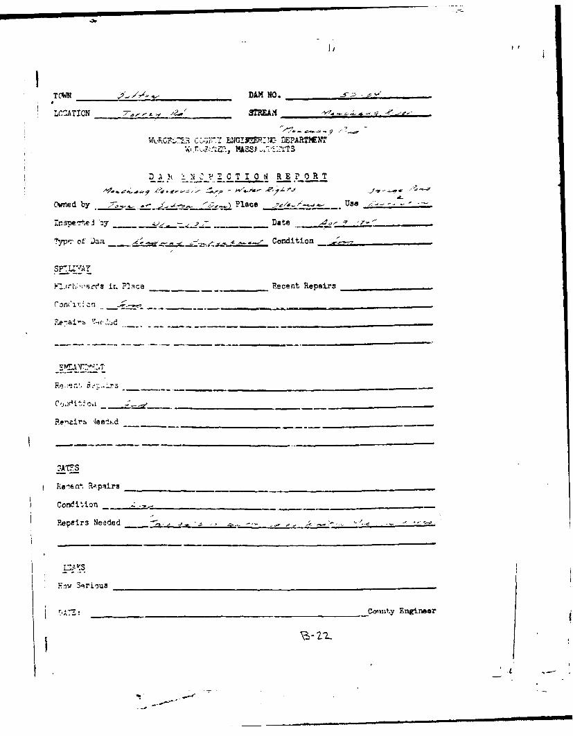
TVW _ _ _ _ _ _ _ _ _ _ _ DAN NO* __4__ _0 ___ ___o
LCCATION 20W(,4E'f
COTMMMI]MNDEPARTIUNT~ NASSACHUSETTS
DAf h z3CIO REPORT
Owned by '.s. ~ ~Place W4,3-1'
Ir spe +AI '.y - - - - -Date /9'-"
T~YP'- of D.tI1 Al Condition
SrLrfAyP'*~l,~:sir. M)ace _ _______Recent Repairs __________
C -ri!on r, -o ~ e~ n-
Re'ai's N-jclrd___
Revnairs leel*.d _____________________
GATE S
Repairs Needed ________________________________
Fay Sgrious
DA'M~ __ __ _ __ __ _ __ _ __ __ _ __ _ zoi

TOWN ___________._ DAM NO._ _ -_-_
LOCATION /_____z___ _ STREAM A.,. A--=A:
WORCESTER COUNTY ENGINEERING DEPARTMENT
WORCESTER, MASSACHUSETTS
DAM INSPECTION REPORT
Owned by / -. Place JyL.. .,/iL Use A-. /2 '... . .
Inspected by ___._____Date _________
Type of Dam , Condition _-_,
SPILLWAY
Flashboards in Place 4 . / ReoentRepairs
Conditior " .,-.- . =,-..
Repairs Needed
EMBAHKMENT
Recent Repairs
Condition _.___-_
:,epairs Needed
OATEE
Recent Repairs
Conditions -. .
Repairs Needed
LEA.kTS
How Serious ', .. .
DATE: -County Engineer
- mI LSI

-
K..
- ~17-_1
-75:7'7
_ _ 4:- -*
-F -
-7 I LI - t i
3 0 40 5 0ro " L -Es za c9mofN"
II
BY.__ -_ ..... T- - -'--- LOUIS BERGER & ASSOCIATES INC. SHEET No. .CHKD. BY .---- DATE------------" PROJECT-- -- -
SUBJECT -- .. .--
I
_jj
o- '. 4 1-
.4', t
-- I, - t-.. '
U _- - ;g, .
II
-T-
. . . l1
--ll I-l Il lll /) l

.-------A _: LOVIS BERGER & ASSOCIATES INC.CHKID. my ----- DATE- .. .,.,,.,; , .. . . SHEET' O... .. ¢ .. .
I(DBY ------ PROJECTI2'.
3 VI 7
II
/ -
Vci/
I
,-.

.. .
- 1Z11 1 _ ___ 1[Zizi
ij
V _____L_
I _-_--- -.- i
.4 4 I
-i
____~M 77 [t-7__________
,)
____. 7 1

11Iml
, DATE LOUIS BERGER & ASSOCIATES INC. SHEET NO----. . .-_CNK.SY OAT ~ ~"-------PROJECT~*
4' '- .. ' " ,
s n e T -- - _ -----'. .- ' .... . -- -I .-------- -- ---- ,._'" . - .
,,. v- \4..,
4,,' 4-I
6,%
__'a =.
-, ,
X
!4 ~

I y-" a-.4.-=_ LOUIS BERGER & ASSOCIATES INC.B Y,___r.--; '. ---. ---- CIA TE ..... SHEET
CH KD . BY .---- DATE --------- . . m --.................... .....- PROJECT .-.. ...
SUBJECT ---- 4 -"----- ---- ---- --------------------- -- ---
II, ' --Lt
4
3s 4 9 4, - 7 *a:C
___c ?Z.. ____
I
) D-9

1,All
3 IiD
'I -J

I t
i
tt
t
1 71
_____ ______ .__2 __ ______.. . . . . . . . ____ ___..__ . .. J .. ! . ____ ___-
....__ 4 -) i I.. j ' -- U ; 1 . .-.
* . i : i . . . .. . . -
-I " I I " fJMN I±. .. .~
-T._ lb_ CRO- C -I ri . I __
I j _ : j I - I - " -,
' ~ 10 0- TO ME .MA RX IN HO R - E t .97 . .. :
___ __ _ ~ _ __ O-I _
-\ - -- -- , -,. . ...____. ... . . .._ _ 1 I . . .. . .
I ' I , . t . . .. . ,_,_
' . ' "/ I : + - '-+ t- . J ' " .. _ I __-_,_: c O + .+ . _ _-
a - + + ,T, ', ':P4 ,'' .,= {-- I- i 1 : - -____i
+ _ _ _ _ _+ ' + + + L + + + \ + + + k j ! +i L +--i + . + + l \ + 1 t ++ : ' ! + +:
_ _ -; + I-:\t + ]] [ i [ r - K ' L- -] i :] f-- - " -- --- 1 .. { ., .+. ., J i ll+ . _ .. - .; .- + -- :
t _ : _+ / C R N T. I_+ + + ! - _ : . + --+ t + : : : ~ : ._+! iH D7 £A PH I:T -
TIME IN HCUPSI I
(I

. -- -- 0ATE... C- - LOUIS BERGER & ASSOCIATES INC. SHEET NO.------- OF ,-I N zY -OAT ....... . _- - --. PROJECT. _ '_ - --------
SUBJECT--- 1; :-C "c- ;z
- -- --- --- - - -- - - - - -- - - - - - - - - -
r- Z
.. ., ..:. - I2_ \,
2--. A, z.Z
04
0-I

4 1,,
I __ ____ ____ ____ ___ ____ ____ ____ ___
- I-__ __ _ __ _ I
I
__Or ___K
'PCI I
___ I V.~ ____
14 __ ~_ __ _ _

Ii
7f Z Z 7Z{Z jZf , 1 IZV] KiX
- ' - -- __ l t ! -. - ] f I i t -1
tO. _ t . _i I .. L
w 0'
~li~l.~-iz 0-
[ 1
-- i ~. i l ,,, I "" 'I'' ' ' -
-7r-
.. iz -f - - _ ± -
: I ' l !i .. ... I l
I
aLj*V I --- I -i l ~ l i m n l m

- I a'
8 , ---.... DATE. - LOUIS BERGER & ASSOCIATES INC. SHEET NO .- --CHKO. BY ----- DATE-- -- -- - - - -- - - PROJECT --- 2 ----
* ~ ~ , v A ', r . -. L". -,__
I o _ - El -- '= - .- ,. -, : - -. .,-
z ,
-
I I - . I l I .I..I I IIII

* 9Y ~ DATEA:i: LOUIS BERGER & ASSOCIATES INC. SHEET NO._i-
-H D 9T--- DATE ---------. J -,- .- D ,
SU JEC1J2 A'--' :.1A,-- ---- - - - -- - - ---- -~ --- -- - - - - - - - - - - - - - -
a .7'- !2
13'a.
_;Z-
4 \~-,Ask

* I,
* *YZ _r .. ,E_-4?_Z LOUIS BERGER & ASSOCIATES INC. SHEET NOO5--- F._
CHK-. -y .....-- AE - -------- PROJECT _- -=_ ---------
I SUBJECTL I ---./ -----_-_-_,-_----..- _------.. . . . . .
A
-7-
.,i.
A -1
. - ,ISoo AIc: ,nC t_:\ l \ aDl;/6I
cot

AU AM 7q85 NATIONAL PROORl FOR INSPECTION OF NON-FEOERAt DAIS /3IMANCHAUG POND DAMI 11A.- UW CORPS OF ENGINEERS WALTHAM MA
NEV ENGLAND DIV JUL S0 FIO 13/13 HL
El"'.!

.2 132
1.8
~1.125 11._4 111.6
MICROCOPY RMSGTIOR4 TEST IARTNATIONAL BURWJ OF SJlJ~-"WME3-A -
-(T
4p A

BY-t, Lz DAE - .2iLOUIS BPERE& ASITES INCb. SHEET .- !
3KO. y---- A TE ----- - -- -NROJ!5
--- --- --- --- --- --- -- --- --- --
z 4 a lc t- 14 yo
t~~-- L\'I-C:
- 71

.DATE " LOUIS BERGER & ASSOCIATES INC. SHEET NO.-- 0F.CHKO. BY - DATE ------ ---- i ", - - - PROJECT ----.
S U B J E C T - - L t - - - - - - - - --- - - - - - --- - - - -- - - - - - - - -
~4 0
if 4
I A
I
3 4C(4.V's ITilI 5I2
i il7Es
Iw

LOUIS BERGER &ASSOCIATESIN. SETN_C K .B -- - - -D A T E - - - --- - - - - - - - - - - -- - - - - SH OE T NO..
j 14.
2 -~ Z 45 -

11 II-
IIIIIIII
Appendix E
Information as Contained in the
National Inventory of Dams
' IIIIIII
-"il
- --- - -
4~I
"I:1
I
SIp
I
UrUL
'5-
~1t~
/~ AT THIS TIME
V L
KI
ml
IF,£Iml
U,
A: -