Embed Size (px)
Citation preview

READ & SAVE THESE INSTRUCTIONS
MIG 140i 120V Inverter MIG Welder
Owner’s Manual
WARNING: Read carefully and understand all ASSEMBLY AND OPERATION
INSTRUCTIONS before operating. Failure to follow the safety rules and other basic safety
precautions may result in serious personal injury.
Item #74220

Page 2 of 31
Thank you very much for choosing a Klutch® product!
For future reference, please complete the owner’s record below:
Serial Number/Lot Date Code: ________________________________
Purchase Date: ____________________________________________
Save the receipt, warranty, and this manual. It is important that you read
the entire manual to become familiar with this product before you begin
using it.
This welder is designed for certain applications only. Northern Tool &
Equipment is not responsible for issues arising from modification or
improper use of this product such as an application for which it was not
designed. We strongly recommend that this product not be modified
and/or used for any application other than that for which it was designed.
For technical questions, please call 1-800-222-5381.

Page 3 of 31
Table of Contents
Intended Use .......................................................................................................................................... 4
Packaging Contents .............................................................................................................................. 4
Technical Specifications ...................................................................................................................... 4
Important Safety Information ............................................................................................................... 5
Specific Operation Warnings ............................................................................................................... 6
Main Parts of MIG140i ......................................................................................................................... 11
Setting Up Equipment ......................................................................................................................... 12
Before Each Use .................................................................................................................................. 18
Operating Instructions ........................................................................................................................ 19
After Each Use ..................................................................................................................................... 25
Maintenance ........................................................................................................................................ 25
Troubleshooting .................................................................................................................................. 26
Parts Diagram ...................................................................................................................................... 28
Parts List .............................................................................................................................................. 28
Replacement Parts .............................................................................................................................. 29
Limited Warranty ................................................................................................................................. 30

Page 4 of 31
Intended Use
The Klutch MIG 140i is an inverter-powered, wire feed welder for flux core and MIG welding. It comes
complete with a regulator and gas hose for easy connection for MIG. Directly connect this unit to a
120V household power. It is designed to weld materials as thin as 24 gauge all the way up to 3/16" in
a single pass.
Welding with a flux core wire gives the operator the flexibility to use this wire feed welder for mobile
applications, including outdoor applications. The flux core wire does not require the use of a separate
shielding gas which can be blown away by the wind in outdoor applications. Since flux core welding
does not use shielding gas, the operator will not have to have shielding gas bottles, or use the
regulator and gas hose.
Welding with a MIG wire does require the use of a bottle of shielding gas. See the Set-Up guide inside
the wire compartment door for recommendations on shielding gas based on the material you are
welding. MIG welding is limited to indoor applications or applications where the influence of wind can
be controlled to prevent the shielding gas from blowing away. MIG welding allows you to weld thinner
materials without burn-through. It also creates a much cleaner weld with less spatter and no slag. The
result is little post-weld cleaning of the weld joint.
This unit is intended to be used on a 20-amp 120V AC circuit without the use of an extension cord. If
an extension cord is necessary for your application, use the appropriate size and length of extension
cord that will handle 20 amps the entire length of the extension. We highly recommend talking with a
qualified electrician for cord size recommendations.
High frequency, inverter-based welding is more efficient and provides better control than non-inverter
welding machines.
Packaging Contents
• MIG 140i Welder • MIG Torch • Ground Cable/Clamp
• MIG Nozzle • 10 ft. Gas Hose • Dual Gauge Regulator
• Flux Core Nozzle • .030 Contact Tips • Owner’s Manual
Technical Specifications
Property Specification
Power Supply 120V, 20A, 50/60 Hz, Single Phase
No-Load Voltage 60V DC
Output Range - MIG 30A/15.5V to 90A/18.5 DC
Duty Cycle 30% @ 90A
Suggested Wire Steel, Stainless Steel
Suggested Wire Diameter .023, .030, .035
Dimensions 16-7/10ʺ x 7-6/10ʺ x 10-6/10ʺ
Weight 19.4 lb.

Page 5 of 31
Important Safety Information
⚠WARNING
• Read and understand all instructions. Failure to follow all instructions may result in serious injury
or property damage.
• The warnings, cautions, and instructions in this manual cannot cover all possible conditions or
situations that could occur. Exercise common sense and caution when using this tool. Always be
aware of the environment and ensure that the tool is used in a safe and responsible manner.
• Do not allow persons to operate or assemble the product until they have read this manual and
have developed a thorough understanding of how it works.
• Do not modify this product in any way. Unauthorized modification may impair the function and/or
safety and could affect the life of the product. There are specific applications for which the product
was designed.
• Use the right tool for the job. DO NOT attempt to force small equipment to do the work of larger
industrial equipment. There are certain applications for which this equipment was designed. It will
be a safer experience and do the job better at the capacity for which it was intended. DO NOT use
this equipment for a purpose for which it was not intended.
• Industrial or commercial applications must follow OSHA requirements.
⚠WARNING
WORK AREA SAFETY
• Inspect the work area before each use. Keep work area clean, dry, free of clutter, and well-lit.
Cluttered, wet, or dark work areas can result in injury. Using the product in confined work areas
may put you dangerously close to cutting tools and rotating parts.
• Do not use the product where there is a risk of causing a fire or an explosion; e.g., in the presence
of flammable liquids, gases, or dust. The product can create sparks, which may ignite the
flammable liquids, gases, or dust.
• Do not allow the product to come into contact with an electrical source. The tool is not insulated
and contact will cause electrical shock.
• Keep children and bystanders away from the work area while operating the tool. Do not allow
children to handle the product.
• Be aware of all power lines, electrical circuits, water pipes, and other mechanical hazards in your
work area. Some of these hazards may be hidden from your view and may cause personal injury
and/or property damage if contacted.

Page 6 of 31
⚠WARNING
PERSONAL SAFETY
• Stay alert, watch what you are doing, and use common sense when operating the tool. Do not use
the tool while you are tired or under the influence of drugs, alcohol, or medication. A moment of
inattention while operating the tool may result in serious personal injury.
• Dress properly. Do not wear loose clothing, dangling objects, or jewelry. Keep your hair, clothing
and gloves away from moving parts. Loose clothes, jewelry, or long hair can be caught in moving
parts. Air vents on the tool often cover moving parts and should be avoided.
• Wear the proper personal protective equipment when necessary. Use ANSI Z87.1 compliant safety
goggles (not safety glasses) with side shields, or when needed, a face shield. Use a dust mask in
dusty work conditions. Also use non-skid safety shoes, hardhat, gloves, dust collection systems,
and hearing protection when appropriate. This applies to all persons in the work area.
• Do not overreach. Keep proper footing and balance at all times.
⚠CAUTION
WELDER USE AND CARE
• Do not force the welder. Products are safer and do a better job when used in the manner for which
they are designed. Plan your work, and use the correct product for the job.
• Check for damaged parts before each use. Carefully check that the product will operate properly
and perform its intended function. Replace damaged or worn parts immediately. Never operate the
product with a damaged part.
• Store the product when it is not in use. Store it in a dry, secure place out of the reach of children.
Inspect the tool for good working condition prior to storage and before re-use.
• Use only accessories that are recommended by the manufacturer for use with your product.
Accessories that may be suitable for one product may create a risk of injury when used with
another tool. Never use an accessory that has a lower operating speed or operating pressure than
the tool itself.
• Keep guards in place and in working order. Never operate the product without the guards in place.
Specific Operation Warnings
⚠WARNING
Your Welding Environment
• Keep the environment you will be welding in free from flammable materials.
• Always keep a fire extinguisher accessible to your welding environment.

Page 7 of 31
• Always have a qualified person install and operate this equipment.
• Make sure the area is clean, dry, and ventilated. Do not operate the welder in humid, wet, or
poorly ventilated areas.
• Always have your welder maintained by a qualified technician in accordance with local, state and
national codes.
• Always be aware of your work environment. Be sure to keep other people, especially children,
away from you while welding.
• Keep harmful arc rays shielded from the view of others.
• Mount the welder on a secure bench or cart that will keep the welder secure and prevent it from
tipping over or falling.
⚠WARNING
Your Welder’s Condition
• Check the ground cable, power cord, and welding cable to be sure the insulation is not damaged.
Always replace or repair damaged components before using the welder.
• Check all components to ensure they are clean and in good operating condition before use.
⚠CAUTION
During Operation
Do not operate the welder if the output cable, electrode, torch, or any accessories are wet. Do
not immerse them in water. These components and the welder must be completely dry before
attempting to use them.
• Follow the instructions in this manual.
• Keep the welder in the OFF position when not in use.
• Connect ground lead as close to the area being welded as possible to ensure a good ground.
• Do not allow any body part to come in contact with the welding electrode if you are in contact with
the material being welded, ground, or electrode from another welder.
• Do not weld if you are in an awkward position. Always have a secure stance while welding to
prevent accidents. Wear a safety harness if working above ground.
• Do not drape cables over or around your body.
• Wear a full coverage helmet with appropriate shade (see ANSI Z87.1 safety standard) and safety
glasses while welding.
• Wear proper gloves and protective clothing to prevent your skin from being exposed to hot metals,
UV, and IR rays.
• Do not overuse or overheat your welder. Allow proper cooling time between duty cycles.

Page 8 of 31
• Keep hands and fingers away from moving parts.
• Do not point the torch at a body part of yours or anyone else’s.
• Always use this welder in the rated duty cycle to prevent excessive heat and failure.
⚠WARNING
Electrical Shock
Electric arc welders can produce a shock that can cause injury or death. Touching electrically live
parts can cause fatal shocks and severe burns. While welding, all metal components connected to the
wire are electrically hot. Poor ground connections are a hazard, so secure the ground lead before
welding.
• Wear dry protective apparel: coat, shirt, gloves and insulated footwear.
• Insulate yourself from the work piece. Avoid contacting the work piece or ground.
• Do not attempt to repair or maintain the welder while the power is on.
• Inspect all cables and cords for any exposed wire and replace immediately if found.
• Use only recommended replacement cables and cords.
• Always attach the ground clamp to the work piece or work table as close to the weld area as
possible.
• Do not touch the welding wire and the ground or grounded work piece at the same time.
• Do not use a welder to thaw frozen pipes.
⚠WARNING
Fumes and Gases
• Do not use the plasma cutter in the presence of gasoline, diesel, propane, or other flammable
liquids. Sparks created from the cutter may ignite liquids or fumes, causing an explosion and
serious injury or death.
• Fumes emitted from the welding process displace clean air and can result in injury or death.
• Do not breathe in fumes emitted by the welding process. Make sure your breathing air is clean
and safe.
• Work only in a well-ventilated area or use a ventilation device to remove welding fumes from the
environment where you will be working.
• Do not weld on coated materials (galvanized, cadmium plated or containing zinc, mercury, or
barium). They will emit harmful fumes that are dangerous to breathe. If necessary use a ventilator,
respirator with air supply, or remove the coating from the material in the weld area.
• The fumes emitted from some metals when heated are extremely toxic. Refer to the material

Page 9 of 31
safety data sheet for the manufacturer’s instructions.
• Do not weld near materials that will emit toxic fumes when heated. Vapors from cleaners, sprays,
and degreasers can be highly toxic when heated.
⚠WARNING
UV and IR Arc Rays
The welding arc produces ultraviolet (UV) and infrared (IR) rays that can cause injury to your
eyes and skin. Do not look at the welding arc without proper eye protection.
• Always use a helmet that covers your full face from the neck to top of head and to the back of
each ear.
• Use a lens that meets ANSI standards and safety glasses. For welders under 160 amps output,
use a shade 10 lens; for above 160 amps, use a shade 12. Refer to the ANSI standard Z87.1 for
more information.
• Cover all bare skin areas exposed to the arc with protective clothing and shoes. Flame-retardant
cloth or leather shirts, coats, pants, or coveralls are available for protection.
• Use screens or other barriers to protect other people from the arc rays emitted from your welding.
• Warn people in your welding area when you are going to strike an arc so they can protect
themselves.
⚠WARNING
Fire Hazards
Do not weld on containers or pipes that contain or have had flammable, gaseous, or liquid
combustibles in them. Welding creates sparks and heat that can ignite flammable and
explosive materials.
• Do not operate any electric arc welder in areas where flammable or explosive materials are
present.
• Remove all flammable materials within 35 feet of the welding arc.
• Take precautions to ensure that flying sparks do not cause fires or explosions in hidden areas,
cracks, or areas you cannot see.
• Keep a fire extinguisher close in the case of fire.
• Wear garments that are oil-free with no pockets or cuffs that will collect sparks.
• Do not have on your person any items that are combustible, such as lighters or matches.
• Keep work lead connected as close to the weld area as possible to prevent any unknown,
unintended paths of electrical current from causing electrical shock and fire hazards.

Page 10 of 31
• To prevent any unintended arcs, cut the wire back to ¼" stick out after welding.
⚠CAUTION
Hot Materials - Welded materials are hot and can cause severe burns if handled improperly.
• Do not touch welded materials with bare hands.
• Do not touch the torch nozzle after welding until it has had time to cool down.
⚠CAUTION
Electromagnetic Field
• Electromagnetic fields can interfere with various electrical and electronic devices such as
pacemakers.
• Consult your doctor before using any electric arc welder or cutting device.
• Keep people with pacemakers away from your welding area when welding.
• Do not wrap cable around your body while welding.
• Wrap the torch and ground cable together whenever possible.
• Keep the torch and ground cables on the same side of your body.
H.F. RADIATION can cause interference!
• High-frequency (H.F.) can interfere with radio navigation, safety services, computers, and
communications equipment.
• Have only qualified persons familiar with electronic equipment perform this installation.
• The user is responsible for having a qualified electrician promptly correct any interference problem
resulting from the installation.
• If notified by the FCC about interference, stop using the equipment at once.
• Have the installation regularly checked and maintained.
• Keep high-frequency source doors and panels tightly shut, keep spark gaps at correct setting, and
use grounding and shielding to minimize the possibility of interference.
ARC welding can cause interference!
• Electromagnetic energy can interfere with sensitive electronic equipment such as computers and
computer-driven equipment such as robots.
• Be sure all equipment in the welding area is electromagnetically compatible.
• To reduce possible interference, keep weld cables as short as possible, close together, and down
low, such as on the floor.
• Locate welding operation 100 yards from any sensitive electronic equipment.

Page 11 of 31
• Be sure this welding machine is grounded.
• If interference still occurs, the user must take extra measures such as moving the welding
machine, using shielded cables, using line filters, or shielding the work area.
⚠WARNING
Shielding Gas Cylinders Can Explode
High pressure cylinders can explode if damaged; treat them carefully.
• Never expose cylinders to high heat, sparks, open flames, mechanical shocks or arcs.
• Do not touch the cylinder with the MIG gun.
• Do not weld on the cylinder.
• Always secure cylinder upright to a cart or stationary object.
• Keep cylinders away from welding or electrical circuits.
• Use the proper regulators, gas hose, and fittings for the specific application.
• Do not look into the valve when opening it.
• Use a protective cylinder cap whenever possible.
Main Parts of MIG140i
1
3
2

Page 12 of 31
Figure 1
Reference Subassembly
1 MIG 140i
2 MIG Torch
3 Ground Cable & Clamp
Setting Up Equipment
⚠WARNING
ELECTRIC SHOCK CAN KILL!
• High voltage danger from power source! Consult a qualified electrician for proper installation of
receptacle. This welder must be grounded while in use to protect the operator from electrical
shock.
• Do not remove grounding prong or alter the plug in any way. Use only the supplied adapter
between the welder's power cord and the power source receptacle. Make sure the POWER switch
is OFF then connect your welder's power cord to a properly grounded 120 VAC (110V-130V), 60
Hz, single phase, 20-amp power source.
1. POWER REQUIREMENT 120V - AC single phase 120V (110-130V) 50/60 HZ fused with a 20-
amp time delayed fuse or circuit breaker is required. DO NOT OPERATE THIS UNIT if the
ACTUAL power source voltage is less than 110 volts AC or greater than 130 volts AC.
2. EXTENSION CORD - We do not recommend an extension cord because of the voltage drop
produced. This drop in voltage can affect the performance of the welder. If you need to use an
extension cord, check with a qualified electrician and your local electrical codes for your specific
area.
3. INSTALL THE WIRE ROLLER - The wire roller has been factory installed. However, check to make certain the correct wire groove is in place to accommodate the size of wire you are using. Open the wire feed compartment. Adjust the drive roller according to the following steps, see the following images regarding the wire feeder structure (figure 2).
a. Open the door to the welder drive compartment. b. Remove the drive tension by loosening the drive tension adjusting knob (1) and lifting the
Drive Tension Adjustor away from the Drive Tension Arm (2). Lift the Drive Tension Arm away from the Drive Roller (3).
c. If there is wire already installed in the welder, roll it back onto the wire spool by hand-turning the spool clockwise. Be careful not to let all of the wire come out of the rear end of the inlet guide tube without holding onto it or the wire spool will unspool itself. Put the end of the wire into the hole on the outside edge of the wire spool and bend it over to hold the wire in place. Remove the spool of wire from the drive compartment of the welder.
d. Rotate the Drive Roller Cap (3) counter-clockwise and remove it from the Drive Roller. e. Pull the Drive Roller off the Drive Roller shaft. f. Based on the wire diameter, select the correct groove. When installing the drive roller, the
number stamped on the drive roller for the wire size you are using should be facing you. Push the Drive Roller onto the Drive Roller Shaft.
g. Reinstall the Drive Roller Cap and lock in place by turning it clockwise. h. Close the door to the welder drive compartment.

Page 13 of 31
4. INSTALL THE WIRE a. Select welding wire - We recommend the use of .030 Wire on this unit. However, .023 -
.035 wire may be used. Both four-inch and eight-inch wire spools can be used on this welder.
Figure 2
NOTE:
- Metal thinner than 24-gauge cannot be welded with this machine. Attempting to do so will cause burn-
through in the metal you are intending to weld.
- Do not use rusty wire. Remove any wire that is rusty. If the whole spool is rusty, discard it and use
another roll.
⚠WARNING
ELECTRIC SHOCK CAN KILL!
Always turn the power switch OFF and unplug the power cord from the AC power source before
installing wire.
NOTE: Before installing, make sure that you have removed any old wire from the torch assembly.
This will help to prevent the possibility of the wire jamming inside the gun liner.
NOTE: Be very careful when removing the welding nozzle. The contact tip on this welder is live
whenever the torch trigger is pulled. Make certain power is turned OFF.
i. Remove the nozzle and contact tip from the end of the torch assembly. See
Figure 3.
ii. Make sure the proper groove on the drive roller is in place for the wire installed. If
not, change the drive roller as described in a previous section, INSTALL THE
WIRE ROLLER.
iii. Remove the packaging from the spool of wire and then identify the leading end of
the wire secured on the edge of the spool. DO NOT UNHOOK IT AT THIS TIME.

Page 14 of 31
Figure 3
iv. Place the spool on the spool hub so the wire will pull off the bottom of the spool.
The welding wire should always come off the bottom of the spool into the drive
mechanism (Figure 4).
Figure 4
v. The welder can use either 4 inches or 8-inch spools. See Figure 5 for additional
reference. The wing nut controls the tension on the spool.
Figure 5
4 Inch 8 Inch
MIG Nozzle
Flux Core Nozzle
Contact Tip
Page 15 of 31
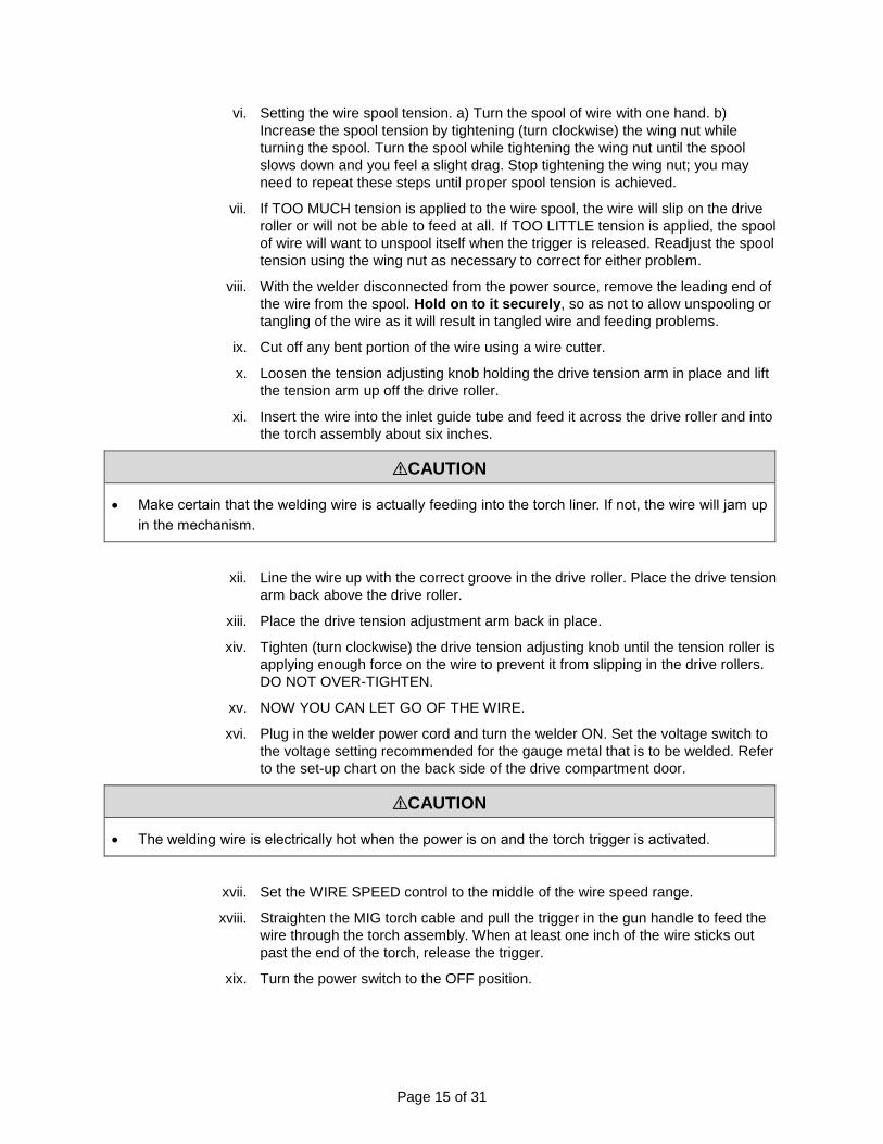
vi. Setting the wire spool tension. a) Turn the spool of wire with one hand. b)
Increase the spool tension by tightening (turn clockwise) the wing nut while
turning the spool. Turn the spool while tightening the wing nut until the spool
slows down and you feel a slight drag. Stop tightening the wing nut; you may
need to repeat these steps until proper spool tension is achieved.
vii. If TOO MUCH tension is applied to the wire spool, the wire will slip on the drive
roller or will not be able to feed at all. If TOO LITTLE tension is applied, the spool
of wire will want to unspool itself when the trigger is released. Readjust the spool
tension using the wing nut as necessary to correct for either problem.
viii. With the welder disconnected from the power source, remove the leading end of
the wire from the spool. Hold on to it securely, so as not to allow unspooling or
tangling of the wire as it will result in tangled wire and feeding problems.
ix. Cut off any bent portion of the wire using a wire cutter.
x. Loosen the tension adjusting knob holding the drive tension arm in place and lift
the tension arm up off the drive roller.
xi. Insert the wire into the inlet guide tube and feed it across the drive roller and into
the torch assembly about six inches.
⚠CAUTION
• Make certain that the welding wire is actually feeding into the torch liner. If not, the wire will jam up
in the mechanism.
xii. Line the wire up with the correct groove in the drive roller. Place the drive tension
arm back above the drive roller.
xiii. Place the drive tension adjustment arm back in place.
xiv. Tighten (turn clockwise) the drive tension adjusting knob until the tension roller is
applying enough force on the wire to prevent it from slipping in the drive rollers.
DO NOT OVER-TIGHTEN.
xv. NOW YOU CAN LET GO OF THE WIRE.
xvi. Plug in the welder power cord and turn the welder ON. Set the voltage switch to
the voltage setting recommended for the gauge metal that is to be welded. Refer
to the set-up chart on the back side of the drive compartment door.
⚠CAUTION
• The welding wire is electrically hot when the power is on and the torch trigger is activated.
xvii. Set the WIRE SPEED control to the middle of the wire speed range.
xviii. Straighten the MIG torch cable and pull the trigger in the gun handle to feed the
wire through the torch assembly. When at least one inch of the wire sticks out
past the end of the torch, release the trigger.
xix. Turn the power switch to the OFF position.

Page 16 of 31
xx. Select a contact tip stamped with the same diameter as the wire being used.
NOTE: Due to inherent variances in flux core welding wire, it may be necessary
to use a contact tip one size larger than your flux core wire, if wire jams occur.
xxi. Slide the contact tip over the wire (protruding from the end of the torch). Thread
the contact tip into the end of the torch and hand-tighten securely.
xxii. Install the nozzle on the torch assembly.
xxiii. Cut off excess wire that extends past the end of the nozzle more than 1/4 inch.
xxiv. Turn the welder ON.
5. SETTING THE DRIVE ROLL TENSION
⚠WARNING
• Arc flash can injure eyes! To reduce the risk of arc flash, make certain that the wire coming out of
the end of the torch does not come into contact with the work piece, ground clamp, or any grounded
material during the drive tension setting process or arcing will occur.
a. Press the trigger on the torch.
b. Turn the drive tension adjustment knob clockwise until the wire seems to feed smoothly
without slipping.
6. GAS INSTALLATION
⚠WARNING
Shielding gas cylinders and high-pressure cylinders can explode if damaged; handle them
carefully.
• Never expose cylinders to high heat, sparks, open flames, mechanical shocks, or arcs.
• Do not weld on the cylinder.
• Always secure the cylinder upright to a cart or stationary object.
• Keep cylinders away from welding or electrical circuits.
• Use the proper regulators, gas hoses, and fittings for the specific application.
Figure 6

Page 17 of 31
a. Connect one end of the gas hose to the gas hose connection on the back of the welder. b. Connect the other end of the gas hose to the gas hose connection on the supplied
regulator/flow gauge. c. Before installing the regulator, it is good practice to make certain there is not debris in the
gas bottle connection. Rotate the bottle so the gas connection is not pointing toward you or any other person. Turn the valve on the gas bottle clockwise and quickly close it. This quick thrust of gas will clear any debris in the connection. Connect the regulator to the gas bottle connection. Use a wrench to snug up the connection.
(1) Gas Bottle Valve
(2) Gas Flow Gauge (Set at 20 CFH)
(3) Gas Pressure Gauge
(4) Regulator
(5) Gas Flow Adjuster
(6) Gas Hose Connection
(7) Gas Cylinder
d. Open the Gas Bottle Valve on the cylinder of gas. e. Turn the Gas Flow Adjuster on the regulator so that the gas flow rate is set at approximately
20 CFH. Make certain you are reading the correct scale on the gauge.
NOTE: Slowly open the cylinder valve by turning it counter-clockwise until the cylinder pressure gauge
registers on the first gauge of the regulator. Turn the adjustment knob clockwise (right) slowly to increase
gas flow to 20 CFH. To reduce the gas flow, turn the adjustment counter-clockwise (left). The gas valve is
located on the back panel of the welder and activated by the trigger. Gas flow should be heard when the
trigger is activated. No gas flow will result in a harsh arc with excessive spatter, a smooth weld bead will
be difficult to obtain. Avoid unnecessary gas loss by closing the tank valve when finished welding.
1
7
4
3 2
6
5

Page 18 of 31
6.7 GAS SELECTION
Different materials require different shielding gas when MIG welding, refer to the set-up chart inside the
wire feed compartment.
Mild Steel: Use 75% Argon and 25% CO2 for reduced spatter and reduced penetration for thinner
materials. Do NOT USE Argon gas concentrations higher than 75% on steel. The result will be poor
penetration, porosity, and brittleness of weld.
Mild Steel: Use CO2 for deeper penetration but increased spatter. (A CO2 regulator adapter will be
needed.)
Stainless Steel: Use a mixed gas consisting of Helium, Argon, and CO2.
Aluminum or Bronze: Use 100% Argon.
7. CHANGING THE POLARITY
a. Polarity Changing - When MIG wire is used, shielding gas is required and the polarity on this unit needs to be electrode positive.
b. Electrode Positive for MIG Welding - The Weld Power Cable should be connected to the positive (+) weld output connection on the front of the machine. The ground cable would then be connected to the negative (-) weld output connection.
c. Electrode Negative for Flux Core Welding - The Weld Power Cable should be connected to the negative (-) weld output connection on the front of the machine. The ground cable would then be connected to the positive (+) weld output connection. Refer to the polarity setting label inside the wire compartment.
Before Each Use
⚠WARNING
ELECTRIC SHOCK CAN KILL!
• Touching live electrical parts can cause fatal shocks or severe burns. Do not touch live electrical
parts.
• Wear dry, hole-free insulating gloves and body protection.
• Disconnect input power before installing, maintaining or servicing this equipment. Lockout/tag out
input power according to OSHA 29 CFR 1910.147.
1. Review the contents of this manual and follow all safety warnings and cautions. 2. Inspect all cords and power cables. Replace any cords or power cables that are damaged or
cracked. 3. Make certain your equipment is in good working order.
4. Make sure the area is clean, dry, and ventilated. Do not operate the welder in humid, wet, or poorly
ventilated areas.
5. Always be aware of your work environment. Be sure to keep other people, especially children and
animals, away from you while welding.
Page 19 of 31
Operating Instructions
⚠WARNING
High voltage danger from power source!
• Consult a qualified electrician for proper installation of receptacle at the power source. This welder
must be grounded while in use to protect the operator from electrical shock. If you are not sure if
your outlet is properly grounded, have it checked by a qualified electrician. Do not cut off the
grounding prong or alter the plug in any way and do not use any adapter, other than the supplied
adapter, between the welder's power cord and the power source receptacle. Make sure the power
switch is OFF, then connect your welder's power cord to a properly grounded 230 VAC (220V -
240V), 60 HZ, single phase, 50-amp power source. If operating on 120V, attach the 120V Adapter
cord to the unit power cord and then connect the assembly to a properly grounded 120 VAC (110V-
130V), 60 Hz, single phase, 25-amp power source.
MIG OPERATION
1. POWER SWITCH - The power switch supplies electrical current to the welder. Whenever the power switch is in the ON position, the welding circuit is activated. ALWAYS turn the power switch to the OFF position and unplug the welder before performing any maintenance.
2. HOLDING THE TORCH - The best way to hold the welding torch is the way it feels most comfortable to you. While practicing using your new welder, you can experiment holding the torch in different positions until you find the one that seems to work best for you.
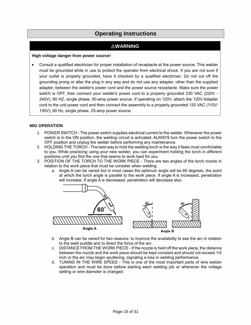
3. POSITION OF THE TORCH TO THE WORK PIECE - There are two angles of the torch nozzle in relation to the work piece that must be consider when welding.
a. Angle A can be varied but in most cases the optimum angle will be 60 degrees, the point at which the torch angle is parallel to the work piece. If angle A is increased, penetration will increase. If angle A is decreased, penetration will decrease also.
b. Angle B can be varied for two reasons: to improve the availability to see the arc in relation to the weld puddle and to direct the force of the arc.
c. DISTANCE FROM THE WORK PIECE - If the nozzle is held off the work piece, the distance between the nozzle and the work piece should be kept constant and should not exceed 1/4 inch or the arc may begin sputtering, signaling a loss in welding performance.
d. TUNING IN THE WIRE SPEED - This is one of the most important parts of wire welder operation and must be done before starting each welding job or whenever the voltage setting or wire diameter is changed.

Page 20 of 31
⚠WARNING
EXPOSURE TO A WELDING ARC IS EXTREMELY HARMFUL TO THE EYES AND SKIN!
• Prolonged exposure to the welding arc can cause blindness and burns. Never strike an arc or begin
welding until you are adequately protected. Wear flame-proof welding gloves, a heavy long-sleeved
shirt, trousers without cuffs, high topped shoes, and an ANSI approved welding helmet.
e. Connect the Ground Clamp to a scrap piece of the same type of material which you will be welding. It should be equal to or greater than the thickness of the actual work piece, and free of oil, paint, rust, etc.
f. Select a heat setting. g. Hold the torch in one hand. Hold the wire just off the work piece. (See step 2 above:
HOLDING THE TORCH, if you are uncertain of the angle at which you will be welding.) h. Set the wire feed speed based on the thickness of material and the set-up chart on the
back side of the wire feeder door. i. Lower your welding helmet and pull the trigger on the torch and let the wire feed into the
work piece to start an arc, and then begin to drag the torch toward you. j. LISTEN! If the arc is sputtering, increase the wire speed slightly and try again. Continue
increasing the wire speed adjustment until you achieve a smooth buzzing sound. If the wire seems to "pound" into the work piece, decrease wire speed slightly and try again. Use the wire speed control to slightly increase or decrease the heat and penetration for a given voltage setting by increasing or decreasing the wire speed slightly. Repeat this tune-in procedure if you select a new voltage setting, a different wire diameter, or a different roll of wire.
4. WELDING TECHNIQUES
⚠WARNING
EXPOSURE TO A WELDING ARC IS EXTREMELY HARMFUL TO THE EYES AND SKIN!
• Prolonged exposure to the welding arc can cause blindness and burns. Never strike an arc or begin
welding until you are adequately protected. Wear flame-proof welding gloves, a heavy long-sleeved
shirt, trousers without cuffs, high topped shoes, and an ANSI approved welding helmet.
⚠WARNING
ELECTRIC SHOCK CAN KILL!
• To prevent ELECTRIC SHOCK, do not perform any welding while standing, kneeling, or lying directly
on the grounded workpiece.
a. Moving the Torch – ‘Torch travel’ refers to the movement of the torch along the weld joint and is broken into two elements: direction and speed. A solid weld bead requires that the welding torch be moved steadily and at the right speed along the weld joint. Moving the torch too fast, too slow, or erratically will prevent proper fusion or create a lumpy, uneven bead.

Page 21 of 31
Travel direction is the direction the torch is moved along the weld joint in relation to the weld puddle. The torch is either PUSHED into the weld puddle or PULLED away from the weld puddle. For most welding jobs you will pull the torch along the weld joint to take advantage of the greater weld puddle visibility. Travel speed is the rate at which the torch is being pushed or pulled along the weld joint. For a fixed heat setting, the faster the travel speed, the lower the penetration and the lower and narrower the finished weld bead. Likewise, the slower the travel speed, the deeper the penetration will be and the higher and wider the finished weld bead will be.
b. Types of Welding Beads - As you become more familiar with your new welder and better
at laying some simple weld beads, you can begin to try some different weld bead types.
The STRINGER BEAD is formed by traveling with the torch in a straight line while keeping the wire and nozzle centered over the weld joint. See the following illustration.
The WEAVE BEAD is used when you want to deposit metal over a wider space than
would be possible with a stringer bead. It is made by weaving from side to side while
moving with the torch. It is best to hesitate momentarily at each side before weaving back
the other way. See the following illustration.

Page 22 of 31
c. Welding Positions The FLAT POSITION is the easiest of the welding positions and is most commonly used. It is best if you can weld in the flat position, if possible, as good results are easier to achieve in this position.
The HORIZONTAL POSITION is performed very much the same as the flat weld except that angle B (see HOLDING THE TORCH) is such that the wire, directed more toward the metal above the weld joint, is to help prevent the weld puddle from running downward while still allowing slow enough travel speed. A good starting point for angle B is about 30 degrees DOWN from being perpendicular to the work piece. In the VERTICAL POSITION, it is easier for many people to pull the torch from top to bottom. It can be difficult to prevent the puddle from running downward. Pushing the torch from bottom to top may provide better puddle control and allow slower rates of travel speed to achieve deeper penetration. When vertical welding, angle B (see HOLDING THE TORCH) is usually always kept at zero, but angle A will generally range from 45 to 60 degrees to provide better puddle control.
The OVERHEAD POSITION is the most difficult welding position. Angle A (see HOLDING THE TORCH) should be maintained at 60 degrees. Maintaining this angle will reduce the chances of molten metal falling into the nozzle. Angle B should be held at zero degrees so that the wire is aiming directly into the weld joint. If you experience excessive dripping of the weld puddle, select a lower heat setting. Also, the weave bead tends to work better than the stringer.
Page 23 of 31
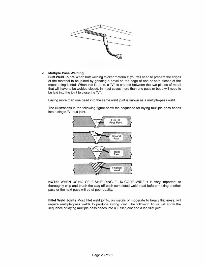
d. Multiple Pass Welding Butt Weld Joints When butt welding thicker materials; you will need to prepare the edges of the material to be joined by grinding a bevel on the edge of one or both pieces of the metal being joined. When this is done, a “V” is created between the two pieces of metal that will have to be welded closed. In most cases more than one pass or bead will need to be laid into the joint to close the “V”. Laying more than one bead into the same weld joint is known as a multiple-pass weld. The illustrations in the following figure show the sequence for laying multiple pass beads into a single “V” butt joint.
NOTE: WHEN USING SELF-SHIELDING FLUX-CORE WIRE it is very important to thoroughly chip and brush the slag off each completed weld bead before making another pass or the next pass will be of poor quality.
Fillet Weld Joints Most fillet weld joints, on metals of moderate to heavy thickness, will require multiple pass welds to produce strong joint. The following figure will show the sequence of laying multiple pass beads into a T fillet joint and a lap fillet joint.

Page 24 of 31
e. Spot Welding
There are three methods of spot welding: Burn-Through, Punch and Fill, and Lap. Each
has advantages and disadvantages, depending on the specific application as well as
personal preference.
i. The BURN-THROUGH METHOD welds two overlapped pieces of metal together by burning through the top piece and into the bottom piece. With the burn-through method, larger wire diameters tend to work better than smaller diameters. Wire diameters that tend to work best, with the burn-through method are 0.035-inch, self-shielding, flux-core wire. Do not use 0.030-inch, self-shielding, flux core wires when using the burn-through method unless the metal is VERY thin or excessive filler metal build-up and minimal penetration is acceptable. Always select the HIGH heat setting with the burn-through method and tune in the wire speed prior to making a spot weld.
ii. The PUNCH AND FILL METHOD produces a weld with the most finished appearance of the three spot weld methods. In this method, a hole is punched or drilled into the top piece of metal and the arc is directed through the hole to penetrate the bottom piece. The puddle can fill up the hole leaving a spot weld that is smooth and flush with the surface of the top piece. Select the wire diameter, heat setting, and tune in the wire speed as if you were welding the same thickness material with a continuous bead.
iii. The LAP SPOT METHOD directs the welding arc to penetrate the bottom and top pieces, at the same time, right along each side of the lap joint seam. Select the wire diameter, heat setting, and tune in the wire speed as if you were welding the same thickness material with a continuous bead.

Page 25 of 31
5. SPOT WELDING INSTRUCTIONS
a. Select the wire diameter and heat setting recommended above for the method of spot welding you intend to use.
b. Tune in the wire speed as if you were creating a continuous weld. c. Hold the nozzle piece completely perpendicular to and about 1/4 inch off the work piece. d. Pull the trigger on the torch and release it when it appears that the desired penetration has
been achieved. e. Make practice spot welds on scrap metal, varying the length of time you hold the trigger,
until a desired spot weld is made. f. Create spot welds on the actual work piece at the desired locations.
After Each Use
⚠CAUTION
Hot Materials - Welded materials are hot and can cause severe burns if handled improperly.
• Do not touch welded materials with bare hands.
• Do not touch the torch nozzle after welding until it has had time to cool down.
1. Turn Off the power switch when not using the equipment. 2. Turn Off any shielding gases you may have used during the operation of this equipment. 3. Inspect all cords and power cables. Replace any cords or power cables that are damaged or
cracked. 4. Disconnect and organize welding cables so they are protected while not in use.
Maintenance
⚠CAUTION
Proper Care, Maintenance, and Repair
• Always have the power disconnected when working on internal components.
• Do not touch or handle the PC board without being properly grounded with a wrist strap. Put the PC
board in a static proof bag to move or ship.
• Do not put hands or fingers near moving parts such as the drive rolls or the fan.
⚠WARNING
ELECTRIC SHOCK CAN KILL!
• Touching live electrical parts can cause fatal shocks or severe burns. Do not touch live electrical
parts
• Wear dry, hole-free insulating gloves and body protection.

Page 26 of 31
• Disconnect input power before installing, maintaining or servicing this equipment. Lockout/tag out
input power according to OSHA 29 CFR 1910.147.
Maintain the welder by adopting a program of conscientious repair and maintenance in accordance with
the following recommended procedures. It is recommended that the general condition of any tool be
examined before it is used. Keep your tool in good repair. Keep all cutting tools sharp and clean. Properly
maintained cutting tools with sharp cutting edges are less likely to bind and are easier to control. Keep
handles dry, clean, and free from oil and grease. The following chart is based on a normal operation
schedule.
Maintenance Interval Maintenance Point
Before Each Use Inspect all cords and power cables. Replace any cords or power cables
that are damaged or cracked.
Every 3 Months
Inspect all warning and caution labels affixed to this unit. If they are
worn, torn or otherwise unreadable, then replace the warning labels.
Inspect and clean and tighten all weld power connections.
Troubleshooting
⚠WARNING
ELECTRIC SHOCK CAN KILL!
• Touching live electrical parts can cause fatal shocks or severe burns. Do not touch live electrical
parts.
• Wear dry, hole-free insulating gloves and body protection.
• Disconnect input power before installing, maintaining or servicing this equipment.
• Lockout/tag out input power according to OSHA 29 CFR 1910.147.
⚠CAUTION
Be aware that the Electrode will be electrically HOT when the Input Power Switch on the welder is
turned on.

Page 27 of 31
Failure Possible Cause Corrective Action
Unit does not power up.
Unit is not plugged in. Plug in unit.
Input power circuit breaker not on. Reset input power circuit breaker.
The main power switch is not working. Replace main power switch.
Protection indicator is on.
The internal temperature is too high. Leave power on and let the fan cool the unit. Output will continue when the unit has cooled.
Input power voltage is too high or too
low.
Meter input power voltage. This unit must be used with input voltage that ranges from 120V AC plus or minus 15%.
Cooling fan is damaged. Replace the cooling fan.
Wire drive motor does not turn.
Wire feed speed control at zero. Increase wire feed speed control.
Trigger is not mashed. Wire will feed only when trigger is
mashed.
Wire drive motor Is damaged. Replace wire drive motor.
Feed roller is not correctly installed. See installation section to correctly install the drive roller.
Wire feeds inconsistently.
Torch liner is plugged. Clear or replace torch liner.
Wire diameter may vary on spool of wire
causing the wire to catch in the contact
tip. Increase the contact tip one size.
Too much or too little wire tension. See Installing the Wire section.
Too much or too little drive roll tension. See Setting Drive Roll Tension section.
Drive roll is worn. Replace drive roll.
Unable to create an arc.
Work piece is painted or rusty. Remove all paint and rust.
Ground clamp is connected where there
is paint or rust. Remove all paint and rust so ground clamp is connected to bare metal.
Ground clamp is not electrically
connected to the work piece. Make certain the ground clamp Is connected to the work piece.
Trigger is not mashed. When in the MIG mode, this unit is not electrically hot until you mash the torch trigger.
Welding arc is unstable, excessive spatter.
The contact tip is too large. Make certain the correct contact tip is installed.
Torch liner is plugged. Clear or replace torch liner.
No shielding gas. Connect shielding gas supply and turn shielding gas on.

Page 28 of 31
Failure Possible Cause Corrective Action
MIG torch is not correctly installed and
shielding gas is not transferring to the
arc.
Remove and reconnect the MIG torch to make certain it is completely installed into the MIG connector.
Wire speed setting is incorrect. Refer to the label inside the wire compartment door for wire speed setting recommendations.
Voltage setting is incorrect. Refer to the label inside the wire compartment door for voltage setting recommendations.
For assistance, contact the Welder Help Line at 877-304-0294.
Parts Diagram
Parts List
Reference Part Number Part Description Quantity
1 105200445 HANDLE 1
2 105100075 HINGE 2
3 125200072 ENCLOSURE 1
** 125400006 WELDER HELP LABEL 1

Page 29 of 31
Reference Part Number Part Description Quantity
** 105200041 WARNING LABEL MIG 1
4 105200446 MIDDLE BOARD 1
5 105200447 MAIN PC BOARD 1
6 105200448 CONTROL PC BOARD 1
7 125200074 FRONT PANEL 1
8 125300013 POTENTIOMETER KNOB 2
9 105400049 CABLE HOLDER 1
10 105200189 GROUND CABLE WITH CLAMP 1
** 105200042 GROUND CLAMP ONLY 1
11 105200190 MIG TORCH 1
12 105200043 CONTACT TIP 11-30 3
13 105200062 MIG NOZZLE 1
** 105200034 FLUX CORE NOZZLE 1
** 105200238 MIG CONTACT TIP ADAPTER 1
14 105200449 STRAIN RELEIF 1
15 105200450 RESISTOR 1
16 105200430 WIRE FEED ASSEMBLY 1
** 105200002 DRIVE ROLLER 1
17 125200078 WELD POWER CONNECTOR (METAL) 2
18 155200046 WELD POWER CONNECTOR (PLASTIC) 2
19 105200009 SPOOL HOLDER 1
19.1 105200010 ADJUSTING NUT 1
19.2 105200012 HOLDER END, LOOSE 1
19.3 105200011 SPRING 1
19.4 105200013 BOLT 1
19.5 105200014 HOLDER END, FIXED 1
20 105500033 FEET 4
21 105200451 BOTTOM 1
22 125200077 FAN 1
23 105300154 STRAIN RELEIF 1
24 105800002 INPUT POWER CABLE 1
25 105200266 GAS CONNECTOR 1
26 105400050 POWER SWITCH 1
27 105200080 DOOR LATCH 1
28 125200073 DOOR 1
** 125200075 OPERATORS MANUAL MIG 140i 1
** 105200081 GAS HOSE TO REGULATOR 1
** 105200082 INERT GAS REGULATOR 1
** Item not shown.
Replacement Parts
• For replacement parts and technical questions, please call Customer Service at 1-800-222-5381.
• Not all product components are available for replacement. The illustrations provided are a convenient
reference to the location and position of parts in the assembly sequence.
• When ordering parts, the following information will be required: item description, item model number,
item serial number/item lot date code, and the replacement part reference number.
• The distributor reserves the rights to make design changes and improvements to product lines and
manuals without notice.
Page 30 of 31
Limited Warranty
Northern Tool and Equipment Company, Inc. ("We'' or "Us'') warrants to the original purchaser only ("You''
or "Your") that the Klutch product purchased will be free from material defects in both materials and
workmanship, normal wear and tear excepted, for a period of three years from date of purchase. The
foregoing warranty is valid only if the installation and use of the product is strictly in accordance with
product instructions. There are no other warranties, express or implied, including the warranty of
merchantability or fitness for a particular purpose. If the product does not comply with this limited
warranty, Your sole and exclusive remedy is that We will, at our sole option and within a commercially
reasonable time, either replace the product or product component without charge to You or refund the
purchase price (less shipping). This limited warranty is not transferable.
Limitations on the Warranty
This limited warranty does not cover: (a) normal wear and tear; (b) damage through abuse, neglect,
misuse, or as a result of any accident or in any other manner; (c) damage from misapplication,
overloading, or improper installation; (d) improper maintenance and repair; and (e) product alteration in
any manner by anyone other than Us, with the sole exception of alterations made pursuant to product
instructions and in a workmanlike manner.
Obligations of Purchaser
You must retain Your product purchase receipt to verify date of purchase and that You are the original
purchaser. To make a warranty claim, contact Us at 1-800-222-5381, identify the product by make and
model number, and follow the claim instructions that will be provided. The product and the purchase
receipt must be provided to Us in order to process Your warranty claim. Any returned product that is
replaced or refunded by Us becomes our property. You will be responsible for return shipping costs or
costs related to Your return visit to a retail store.
Remedy Limits
Product replacement or a refund of the purchase price is Your sole remedy under this limited warranty or
any other warranty related to the product. We shall not be liable for: service or labor charges or damage
to Your property incurred in removing or replacing the product; any damages, including, without limitation,
damages to tangible personal property or personal injury, related to Your improper use, installation, or
maintenance of the product or product component; or any indirect, incidental or consequential damages
of any kind for any reason.
Assumption of Risk
You acknowledge and agree that any use of the product for any purpose other than the specified use(s)
stated in the product instructions is at Your own risk.
Governing Law
This limited warranty gives You specific legal rights, and You also may have other rights which vary from
state to state. Some states do not allow limitations or exclusions on implied warranties or incidental or
consequential damages, so the above limitations may not apply to You. This limited warranty is governed
by the laws of the State of Minnesota, without regard to rules pertaining to conflicts of law. The state
courts located in Dakota County, Minnesota shall have exclusive jurisdiction for any disputes relating to
this warranty.

Page 31 of 31
Distributed by:
Northern Tool & Equipment Company, Inc.
Burnsville, Minnesota 55306
www.northerntool.com
Made in China