Embed Size (px)
Citation preview

Maintenance Manual
Microwave Site Master™ S820ECable and Antenna Analyzer
1 MHz to 8/14/20/30/40 GHz
Anritsu Company490 Jarvis DriveMorgan Hill, CA 95037-2809USA
Part Number: 10580-00345Revision: A
Published: January 2014Copyright 2014 Anritsu Company


S820E MM PN: 10580-00345 Rev. A Safety-1
Safety SymbolsTo prevent the risk of personal injury or loss related to equipment malfunction, Anritsu Company uses the following symbols to indicate safety-related information. For your own safety, please read the information carefully before operating the equipment.
Symbols Used in Manuals
Safety Symbols Used on Equipment and in ManualsThe following safety symbols are used inside or on the equipment near operation locations to provide information about safety items and operation precautions. Ensure that you clearly understand the meanings of the symbols and take the necessary precautions before operating the equipment. Some or all of the following five symbols may or may not be used on all Anritsu equipment. In addition, there may be other labels attached to products that are not shown in the diagrams in this manual.
Danger
This indicates a risk from a very dangerous condition or procedure that could result in serious injury or death and possible loss related to equipment malfunction. Follow all precautions and procedures to minimize this risk.
WarningThis indicates a risk from a hazardous condition or procedure that could result in light-to-severe injury or loss related to equipment malfunction. Follow all precautions and procedures to minimize this risk.
Caution
This indicates a risk from a hazardous procedure that could result in loss related to equipment malfunction. Follow all precautions and procedures to minimize this risk.
This indicates a prohibited operation. The prohibited operation is indicated symbolically in or near the barred circle.
This indicates a compulsory safety precaution. The required operation is indicated symbolically in or near the circle.
This indicates a warning or caution. The contents are indicated symbolically in or near the triangle.
This indicates a note. The contents are described in the box.
These indicate that the marked part should be recycled.

Safety-2 PN: 10580-00345 Rev. A S820E MM
For Safety
Warning Always refer to the operation manual when working near locations at which the alert mark, shown on the left, is attached. If the operation, etc., is performed without heeding the advice in the operation manual, there is a risk of personal injury. In addition, the equipment performance may be reduced.
Moreover, this alert mark is sometimes used with other marks and descriptions indicating other dangers.
Warning
When supplying power to this equipment, connect the accessory 3-pin power cord to a 3-pin grounded power outlet. If a grounded 3-pin outlet is not available, use a conversion adapter and ground the green wire, or connect the frame ground on the rear panel of the equipment to ground. If power is supplied without grounding the equipment, there is a risk of receiving a severe or fatal electric shock.
WarningThis equipment can not be repaired by the operator. Do not attempt to remove the equipment covers or to disassemble internal components. Only qualified service technicians with a knowledge of electrical fire and shock hazards should service this equipment. There are high-voltage parts in this equipment presenting a risk of severe injury or fatal electric shock to untrained personnel. In addition, there is a risk of damage to precision components.
Caution
Electrostatic Discharge (ESD) can damage the highly sensitive circuits in the instrument. ESD is most likely to occur as test devices are being connected to, or disconnected from, the instrument’s front and rear panel ports and connectors. You can protect the instrument and test devices by wearing a static-discharge wristband. Alternatively, you can ground yourself to discharge any static charge by touching the outer chassis of the grounded instrument before touching the instrument’s front and rear panel ports and connectors. Avoid touching the test port center conductors unless you are properly grounded and have eliminated the possibility of static discharge.
Repair of damage that is found to be caused by electrostatic discharge is not covered under warranty.
WarningThis equipment is supplied with a rechargeable battery that could potentially leak hazardous compounds into the environment. These hazardous compounds present a risk of injury or loss due to exposure. Anritsu Company recommends removing the battery for long-term storage of the instrument and storing the battery in a leak-proof, plastic container. Follow the environmental storage requirements specified in the product data sheet.

S820E MM PN: 10580-00345 Rev. A Contents-1
Table of Contents
Chapter 1—General Information
1-1 Introduction . . . . . . . . . . . . . . . . . . . . . . . . . . . . . . . . . . . . . . . . . . . . . . . . . . . . . . . . . . . . . . . . 1-1
1-2 Description . . . . . . . . . . . . . . . . . . . . . . . . . . . . . . . . . . . . . . . . . . . . . . . . . . . . . . . . . . . . . . . . 1-1
Standard Accessories . . . . . . . . . . . . . . . . . . . . . . . . . . . . . . . . . . . . . . . . . . . . . . . . . . . . . 1-1
1-3 Related Documents . . . . . . . . . . . . . . . . . . . . . . . . . . . . . . . . . . . . . . . . . . . . . . . . . . . . . . . . . 1-1
1-4 Options . . . . . . . . . . . . . . . . . . . . . . . . . . . . . . . . . . . . . . . . . . . . . . . . . . . . . . . . . . . . . . . . . . 1-1
1-5 Anritsu Customer Service Centers . . . . . . . . . . . . . . . . . . . . . . . . . . . . . . . . . . . . . . . . . . . . . . 1-1
1-6 Recommended Test Equipment . . . . . . . . . . . . . . . . . . . . . . . . . . . . . . . . . . . . . . . . . . . . . . . . 1-2
1-7 Recommended Tools and Supplies . . . . . . . . . . . . . . . . . . . . . . . . . . . . . . . . . . . . . . . . . . . . . 1-4
1-8 Replaceable Parts and Assemblies . . . . . . . . . . . . . . . . . . . . . . . . . . . . . . . . . . . . . . . . . . . . 1-5
Chapter 2— Performance Verification
2-1 Introduction . . . . . . . . . . . . . . . . . . . . . . . . . . . . . . . . . . . . . . . . . . . . . . . . . . . . . . . . . . . . . . . . 2-1
2-2 Manual Performance Test − Frequency Accuracy Verification . . . . . . . . . . . . . . . . . . . . . . . 2-1
Equipment Required . . . . . . . . . . . . . . . . . . . . . . . . . . . . . . . . . . . . . . . . . . . . . . . . . . . . . . 2-1
Procedure . . . . . . . . . . . . . . . . . . . . . . . . . . . . . . . . . . . . . . . . . . . . . . . . . . . . . . . . . . . . . . 2-1
2-3 Automated Performance Tests . . . . . . . . . . . . . . . . . . . . . . . . . . . . . . . . . . . . . . . . . . . . . . . . 2-3
Test Sequence . . . . . . . . . . . . . . . . . . . . . . . . . . . . . . . . . . . . . . . . . . . . . . . . . . . . . . . . . . 2-3
Test Reports . . . . . . . . . . . . . . . . . . . . . . . . . . . . . . . . . . . . . . . . . . . . . . . . . . . . . . . . . . . . 2-3
Equipment Required for Automated Tests . . . . . . . . . . . . . . . . . . . . . . . . . . . . . . . . . . . . . 2-4
S-parameter Measurements Verification Test . . . . . . . . . . . . . . . . . . . . . . . . . . . . . . . . . . . 2-6
Transmission Dynamic Range Verification . . . . . . . . . . . . . . . . . . . . . . . . . . . . . . . . . . . . . 2-7
Transmission High Level Noise Verification . . . . . . . . . . . . . . . . . . . . . . . . . . . . . . . . . . . . 2-7
Automated Test Procedure . . . . . . . . . . . . . . . . . . . . . . . . . . . . . . . . . . . . . . . . . . . . . . . . . 2-7
Chapter 3—Battery Information
3-1 Introduction . . . . . . . . . . . . . . . . . . . . . . . . . . . . . . . . . . . . . . . . . . . . . . . . . . . . . . . . . . . . . . . . 3-1
3-2 Battery Pack Removal and Replacement . . . . . . . . . . . . . . . . . . . . . . . . . . . . . . . . . . . . . . . . 3-2
Battery Pack Information . . . . . . . . . . . . . . . . . . . . . . . . . . . . . . . . . . . . . . . . . . . . . . . . . . 3-4
Chapter 4—Assembly Removal and Replacement
4-1 Introduction . . . . . . . . . . . . . . . . . . . . . . . . . . . . . . . . . . . . . . . . . . . . . . . . . . . . . . . . . . . . . . . . 4-1
4-2 Electrostatic Discharge Prevention . . . . . . . . . . . . . . . . . . . . . . . . . . . . . . . . . . . . . . . . . . . . . 4-1
4-3 Real Time Clock (RTC) Battery . . . . . . . . . . . . . . . . . . . . . . . . . . . . . . . . . . . . . . . . . . . . . . . 4-1
4-4 Replaceable Parts, Assemblies, and Accessories . . . . . . . . . . . . . . . . . . . . . . . . . . . . . . . . . . 4-1
4-5 Instrument Case for Site Master S820E . . . . . . . . . . . . . . . . . . . . . . . . . . . . . . . . . . . . . . . . . . 4-2
Front and Back . . . . . . . . . . . . . . . . . . . . . . . . . . . . . . . . . . . . . . . . . . . . . . . . . . . . . . . . . . 4-2
Case Outer Components . . . . . . . . . . . . . . . . . . . . . . . . . . . . . . . . . . . . . . . . . . . . . . . . . . 4-3
Opening the Case . . . . . . . . . . . . . . . . . . . . . . . . . . . . . . . . . . . . . . . . . . . . . . . . . . . . . . . . 4-4
Basic Case Parts . . . . . . . . . . . . . . . . . . . . . . . . . . . . . . . . . . . . . . . . . . . . . . . . . . . . . . . . 4-6
Front Panel Components . . . . . . . . . . . . . . . . . . . . . . . . . . . . . . . . . . . . . . . . . . . . . . . . . 4-7
Back Panel Components . . . . . . . . . . . . . . . . . . . . . . . . . . . . . . . . . . . . . . . . . . . . . . . . . . 4-8

Contents-2 PN: 10580-00345 Rev. A S820E MM
Table of Contents (Continued)
4-6 Test Panel Connectors . . . . . . . . . . . . . . . . . . . . . . . . . . . . . . . . . . . . . . . . . . . . . . . . . . . . . . 4-9
4-7 Internal Anatomy of the Site Master S820E . . . . . . . . . . . . . . . . . . . . . . . . . . . . . . . . . . . . . 4-10
Case Assembly Components with Complete PCB . . . . . . . . . . . . . . . . . . . . . . . . . . . . . . 4-10
Case Assembly Components with Motherboard PCB . . . . . . . . . . . . . . . . . . . . . . . . . . . 4-11
Motherboard and Connector Panel . . . . . . . . . . . . . . . . . . . . . . . . . . . . . . . . . . . . . . . . . . 4-11
Motherboard and Connector Panel for Option S820E-0708 . . . . . . . . . . . . . . . . . . . . . . 4-12
Motherboard and Connector Panel for Higher Frequency Options . . . . . . . . . . . . . . . . . 4-13
4-8 Disassembly Sequence Overview . . . . . . . . . . . . . . . . . . . . . . . . . . . . . . . . . . . . . . . . . . . . . 4-14
Removal and Replacement Instructions . . . . . . . . . . . . . . . . . . . . . . . . . . . . . . . . . . . . . 4-14
4-9 Replacements That Do Not Require Opening the Case . . . . . . . . . . . . . . . . . . . . . . . . . . . . 4-15
Removing the Bumpers . . . . . . . . . . . . . . . . . . . . . . . . . . . . . . . . . . . . . . . . . . . . . . . . . . 4-15
Removing the Battery Door and Battery . . . . . . . . . . . . . . . . . . . . . . . . . . . . . . . . . . . . . 4-15
Removing and Replacing the Rotary Knob . . . . . . . . . . . . . . . . . . . . . . . . . . . . . . . . . . . 4-16
Removing and Replacing the Tilt Bail . . . . . . . . . . . . . . . . . . . . . . . . . . . . . . . . . . . . . . . 4-16
4-10 Opening the Instrument Case . . . . . . . . . . . . . . . . . . . . . . . . . . . . . . . . . . . . . . . . . . . . . . . 4-17
Procedure . . . . . . . . . . . . . . . . . . . . . . . . . . . . . . . . . . . . . . . . . . . . . . . . . . . . . . . . . . . . . 4-17
4-11 Closing the Case . . . . . . . . . . . . . . . . . . . . . . . . . . . . . . . . . . . . . . . . . . . . . . . . . . . . . . . . . . 4-22
Installing Battery . . . . . . . . . . . . . . . . . . . . . . . . . . . . . . . . . . . . . . . . . . . . . . . . . . . . . . . 4-22
Restarting the Instrument . . . . . . . . . . . . . . . . . . . . . . . . . . . . . . . . . . . . . . . . . . . . . . . . . 4-22
4-12 Main/VNA PCB and Connector Panel Removal . . . . . . . . . . . . . . . . . . . . . . . . . . . . . . . . . 4-23
Procedure . . . . . . . . . . . . . . . . . . . . . . . . . . . . . . . . . . . . . . . . . . . . . . . . . . . . . . . . . . . . . 4-24
4-13 Main/VNA PCB Assembly Installation. . . . . . . . . . . . . . . . . . . . . . . . . . . . . . . . . . . . . . . . . . . 4-25
Procedure . . . . . . . . . . . . . . . . . . . . . . . . . . . . . . . . . . . . . . . . . . . . . . . . . . . . . . . . . . . . . 4-26
4-14 Connector Panel Removal . . . . . . . . . . . . . . . . . . . . . . . . . . . . . . . . . . . . . . . . . . . . . . . . . . 4-27
Procedure . . . . . . . . . . . . . . . . . . . . . . . . . . . . . . . . . . . . . . . . . . . . . . . . . . . . . . . . . . . . . 4-28
4-15 Connector Panel Installation. . . . . . . . . . . . . . . . . . . . . . . . . . . . . . . . . . . . . . . . . . . . . . . . . . 4-30
4-16 Port Connector Removal . . . . . . . . . . . . . . . . . . . . . . . . . . . . . . . . . . . . . . . . . . . . . . . . . . . 4-31
Procedure . . . . . . . . . . . . . . . . . . . . . . . . . . . . . . . . . . . . . . . . . . . . . . . . . . . . . . . . . . . . . 4-31
4-17 Port Connector Installation . . . . . . . . . . . . . . . . . . . . . . . . . . . . . . . . . . . . . . . . . . . . . . . . . . . 4-33
4-18 Microwave Module Removal . . . . . . . . . . . . . . . . . . . . . . . . . . . . . . . . . . . . . . . . . . . . . . . . 4-34
Procedure . . . . . . . . . . . . . . . . . . . . . . . . . . . . . . . . . . . . . . . . . . . . . . . . . . . . . . . . . . . . . 4-34
4-19 Microwave Module Installation . . . . . . . . . . . . . . . . . . . . . . . . . . . . . . . . . . . . . . . . . . . . . . . . 4-35
4-20 Dual Sampler Assembly Removal . . . . . . . . . . . . . . . . . . . . . . . . . . . . . . . . . . . . . . . . . . . . 4-36
Procedure . . . . . . . . . . . . . . . . . . . . . . . . . . . . . . . . . . . . . . . . . . . . . . . . . . . . . . . . . . . . . 4-36
4-21 Dual Sampler Assembly Installation . . . . . . . . . . . . . . . . . . . . . . . . . . . . . . . . . . . . . . . . . . . . 4-37
4-22 Fan Assembly Removal . . . . . . . . . . . . . . . . . . . . . . . . . . . . . . . . . . . . . . . . . . . . . . . . . . . . 4-38
Procedure . . . . . . . . . . . . . . . . . . . . . . . . . . . . . . . . . . . . . . . . . . . . . . . . . . . . . . . . . . . . . 4-38
4-23 Fan Assembly Installation . . . . . . . . . . . . . . . . . . . . . . . . . . . . . . . . . . . . . . . . . . . . . . . . . . . 4-40
4-24 LCD Assembly Removal . . . . . . . . . . . . . . . . . . . . . . . . . . . . . . . . . . . . . . . . . . . . . . . . . . . . 4-42
Procedure . . . . . . . . . . . . . . . . . . . . . . . . . . . . . . . . . . . . . . . . . . . . . . . . . . . . . . . . . . . . . 4-42
4-25 LCD Assembly Installation . . . . . . . . . . . . . . . . . . . . . . . . . . . . . . . . . . . . . . . . . . . . . . . . . . . 4-46
4-26 Keypad PCB Removal . . . . . . . . . . . . . . . . . . . . . . . . . . . . . . . . . . . . . . . . . . . . . . . . . . . . . 4-46
Procedure . . . . . . . . . . . . . . . . . . . . . . . . . . . . . . . . . . . . . . . . . . . . . . . . . . . . . . . . . . . . . 4-46

S820E MM PN: 10580-00345 Rev. A Contents-3
Table of Contents (Continued)
4-27 Keypad Rubber Membrane and Keypad PCB Installation . . . . . . . . . . . . . . . . . . . . . . . . . 4-48
4-28 Touch Screen Removal . . . . . . . . . . . . . . . . . . . . . . . . . . . . . . . . . . . . . . . . . . . . . . . . . . . . 4-49
Procedure . . . . . . . . . . . . . . . . . . . . . . . . . . . . . . . . . . . . . . . . . . . . . . . . . . . . . . . . . . . . . 4-49
4-29 Touch Screen Replacement . . . . . . . . . . . . . . . . . . . . . . . . . . . . . . . . . . . . . . . . . . . . . . . . . . 4-50
4-30 Rotary Encoder Removal . . . . . . . . . . . . . . . . . . . . . . . . . . . . . . . . . . . . . . . . . . . . . . . . . . . 4-51
Procedure . . . . . . . . . . . . . . . . . . . . . . . . . . . . . . . . . . . . . . . . . . . . . . . . . . . . . . . . . . . . . 4-51
4-31 Rotary Encoder Installation. . . . . . . . . . . . . . . . . . . . . . . . . . . . . . . . . . . . . . . . . . . . . . . . . . . 4-51
4-32 Speaker Removal . . . . . . . . . . . . . . . . . . . . . . . . . . . . . . . . . . . . . . . . . . . . . . . . . . . . . . . . . 4-52
4-33 Speaker Installation . . . . . . . . . . . . . . . . . . . . . . . . . . . . . . . . . . . . . . . . . . . . . . . . . . . . . . . . 4-52
Chapter 5—Troubleshooting
5-1 Introduction . . . . . . . . . . . . . . . . . . . . . . . . . . . . . . . . . . . . . . . . . . . . . . . . . . . . . . . . . . . . . . . . 5-1
5-2 Turn-on Problems. . . . . . . . . . . . . . . . . . . . . . . . . . . . . . . . . . . . . . . . . . . . . . . . . . . . . . . . . . . 5-1
Unit Cannot Boot Up (Battery Powered) . . . . . . . . . . . . . . . . . . . . . . . . . . . . . . . . . . . . . . 5-1
Unit Cannot Boot Up (AC Powered) . . . . . . . . . . . . . . . . . . . . . . . . . . . . . . . . . . . . . . . . . . 5-1
Unit Cannot Complete Boot-Up . . . . . . . . . . . . . . . . . . . . . . . . . . . . . . . . . . . . . . . . . . . . . . 5-1
Unit Boots with No Display . . . . . . . . . . . . . . . . . . . . . . . . . . . . . . . . . . . . . . . . . . . . . . . . . 5-2
5-3 Operating Problems . . . . . . . . . . . . . . . . . . . . . . . . . . . . . . . . . . . . . . . . . . . . . . . . . . . . . . . . . 5-2
Failed Instrument Self Test . . . . . . . . . . . . . . . . . . . . . . . . . . . . . . . . . . . . . . . . . . . . . . . . . 5-2
Return Loss Trace has power dropout when Port 1 is terminated with Short . . . . . . . . . . . 5-3
Transmission Trace has power dropout when Thru Cable is connected between VNA Ports5-3
Appendix A—Test Records
A-1 Introduction . . . . . . . . . . . . . . . . . . . . . . . . . . . . . . . . . . . . . . . . . . . . . . . . . . . . . . . . . . . . . . . . A-1
A-2 S820E Site Master Test Record . . . . . . . . . . . . . . . . . . . . . . . . . . . . . . . . . . . . . . . . . . . . . . . . A-2
VNA Frequency Accuracy . . . . . . . . . . . . . . . . . . . . . . . . . . . . . . . . . . . . . . . . . . . . . . . . . A-2
VNA Measurements Accuracy Verification . . . . . . . . . . . . . . . . . . . . . . . . . . . . . . . . . . . . . A-2
VNA Transmission Dynamic Range . . . . . . . . . . . . . . . . . . . . . . . . . . . . . . . . . . . . . . . . . . A-2
VNA High Level Noise (Trace Noise) . . . . . . . . . . . . . . . . . . . . . . . . . . . . . . . . . . . . . . . . . A-2
Index

Contents-4 PN: 10580-00345 Rev. A S820E MM
Table of Contents (Continued)

S820E MM PN: 10580-00345 Rev. A 1-1
Chapter 1 — General Information
1-1 IntroductionThis manual provides service and maintenance information for the Anritsu Site Master S820E Cable & Antenna Analyzer. The information includes product descriptions, replaceable parts information, performance verification procedures, parts removal and replacement procedures, and troubleshooting information. The following terms are equivalent:
• Soft Key is the same as Submenu Key
• Hard Key is the same as Main Menu Key
Throughout this manual, the following terms apply:
• Site Master refers to the S820E Cable & Antenna Analyzer
1-2 Description The Site Master S820E is a Cable & Antenna Analyzer with frequency coverage up to 40 GHz. It utilizes the very latest technologies to deliver accuracy and performance previously reserved only for benchtop instruments.
Standard Accessories
Refer to the Technical Data Sheet (part number 11410-00749) for lists of standard and optional accessories.
1-3 Related Documents Other documents are available for the Site Master S820E at the Anritsu web site at: www.anritsu.com
• Site Master S820E User Guide – part number 10580-00343
• Site Master S820E Programming Manual – part number 10580-00344
• Site Master S820E Technical Data Sheet – part number 11410-00650
1-4 Options
1-5 Anritsu Customer Service CentersFor the latest service and sales information in your area, please visit the following URL:
http://www.anritsu.com/contact.asp
Choose a country for regional contact information.
Table 1-1. Option Numbers and Descriptions
Option Number Option Description
Option 708 1 MHz to 8 GHz, type N(f) ports
Option 714 1 MHz to 14 GHz, type N(f) ports
Option 720 1 MHz to 20 GHz, type K(m) ports
Option 730 1 MHz to 30 GHz, type K(m) ports
Option 740 1 MHz to 40 GHz, type K(m) ports

1-6 Recommended Test Equipment General Information
1-2 PN: 10580-00345 Rev. A S820E MM
1-6 Recommended Test Equipment The following test equipment is recommended for use in testing and maintaining the Site Master S820E.
Table 1-2. Recommended Test Equipment (1 of 2)
Equipment Critical Specification Recommended
Manufacturer/Model
Frequency CounterFrequency: 1 GHz Anritsu Model MF2412B or
MF2412C
Frequency Reference Frequency: 10 MHz Symmetricom Model
RubiSource T&M
Open/Short/Load(for Option 708)
Frequency: DC to 8 GHzConnector: N(m)
Anritsu Model OSLN50A-8, OSLN50A-18, TOSLN50A-8 or TOSLN50A-18
Open/Short/Load(for Option 708)
Frequency: DC to 8 GHzConnector: N(f)
Anritsu Model OSLNF50A-8, OSLNF50A-18, TOSLNF50A-8 or TOSLNF50A-18
Open/Short/Load(for Options 708 or 714)
Frequency: DC to 18 GHzConnector: N(m)
Anritsu Model OSLN50A-18 or TOSLN50A-18
Open/Short/Load(for Options 708 or 714)
Frequency: DC to 18 GHzConnector: N(f)
Anritsu Model OSLNF50A-18 or TOSLNF50A-18
Verification Kit(for Options 708 or 714)
Connector: N Type Anritsu Model 3663-1
Adapter(for Options 708 or 714)
Frequency: DC to 18 GHzConnector: N(m) to K(m)
Anritsu Model 34NK50
Adapter(for Options 708 or 714)
Frequency: DC to 18 GHzConnector: N(m) to K(f)
Anritsu Model 34NKF50
Torque Wrench(for Options 708 or 714)
3/4 in. (0.75 in.) Open End Wrench12 lbf·in (1.35 N·m)
Anritsu Model 01-200
Open/Short/Load(for Option 720)
Frequency: DC to 20 GHzConnector: K(m)
Anritsu Model TOSLK50A-20 or TOSLK50A-40
Open/Short/Load(for Option 720)
Frequency: DC to 20 GHzConnector: K(f)
Anritsu Model TOSLKF50A-20 or TOSLKF50A-40
Open/Short/Load(for Options 720, 730, or 740)
Frequency: DC to 40 GHzConnector: K(m)
Anritsu Model TOSLK50A-40
Open/Short/Load(for Options 720, 730, or 740)
Frequency: DC to 40 GHzConnector: K(f)
Anritsu Model TOSLKF50A-40 or 28KF50
Verification Kit(for Option 720, 730, or 740)
Connector: K Type Anritsu Model 3668-1
Adapter(for Option 720, 730, or 740)
Frequency: DC to 40 GHzConnector: K(m) to K(f)
Anritsu Model 33KKF50B
Adapter(for Option 720, 730, or 740)
Frequency: DC to 40 GHzConnector: K(f) to K(f)
Anritsu Model 33KFKF50B
Torque Wrench(for Option 720, 730, or 740)
5/16 in. (0.325 in.)Open End Wrench8 lbf· in (0.90 N·m)
Anritsu Model 01-201
RF Coaxial CableFrequency: DC to 40 GHzImpedance: 50 ohmConnector: K(f) to K(m)
Anritsu Model 3670K50-2

General Information 1-6 Recommended Test Equipment
S820E MM PN: 10580-00345 Rev. A 1-3
RF Coaxial CableImpedance: 50 ohmConnector: BNC(m) to BNC(m)
Anritsu Part Number 2000-1627-R
Interface CableUSB: USB A to USB mini BEthernet: RJ48, cross-over, Cat.5EEthernet: RJ48, Cat.5E
Anritsu Part Number 3-2000-1498Anritsu Part Number 3-806-152Anritsu Part Number 2000-1371-R
Connector Wrench Anritsu Part Number 01-204
Personal Computer
Operating System: Windows 7Interface: Ethernet, RJ-48Software: National Instruments VISA version 4.4.1 or later
Any
System Verification Software Anritsu Part Number 2300-555
Table 1-2. Recommended Test Equipment (2 of 2)
Equipment Critical Specification Recommended
Manufacturer/Model

1-7 Recommended Tools and Supplies General Information
1-4 PN: 10580-00345 Rev. A S820E MM
1-7 Recommended Tools and Supplies• Medium Phillips-head Screwdriver
• 7.5 lbf·in (0.85 N·m) Torque-Limiting Phillips-head Screwdriver
• Felo brand Series Nm adjustable torque screwdriver set, 0.6 N·m to 1.5 N·m
• Small Flat-Blade Screwdriver, with tip width of less than 3.5 mm – For Front Panel Keypad Bezels
• Small square of rubber or similar non-scratch material approximately 25 mm x 25 mm (1 in x 1 in) – For Front Panel Keypad Bezels
• 5.5 mm Angled-Head Open End Wrench
• 5/16 inch (~8 mm) Open End Wrench, 2 each recommended – For SMA and K Connectors
• 5/16 inch and 8 lbf·in (0.9 N·m) Open End Torque Wrench
• Anritsu Model 01-201
• 7/16 inch (~12 mm) Nut Driver – For Rotary Encoder
• 3/4 inch and 12 lbf·in (1.35 N·m) Open End Torque Wrench, Anritsu Model 01-200
• Needle-Nose Pliers
• Small Cable Ties
• Scraper Tool – For removing RTV from connectors
• Room Temperature Vulcanizing (RTV) Silicon Sealant – For Keypad Flex PCB Replacement
Anritsu Part Number 3-783-1102
• Approved cleaning supplies – For touch screen of the LCD Display, and instrument Case

General Information 1-8 Replaceable Parts and Assemblies
S820E MM PN: 10580-00345 Rev. A 1-5
1-8 Replaceable Parts and Assemblies To ensure that the correct options are provided on the replacement assembly when ordering a Main/VNA PCB Assembly, all installed instrument options must be declared on the order.
The installed options are listed on a label on the back of the S820E. They can also be viewed in the System Status display.
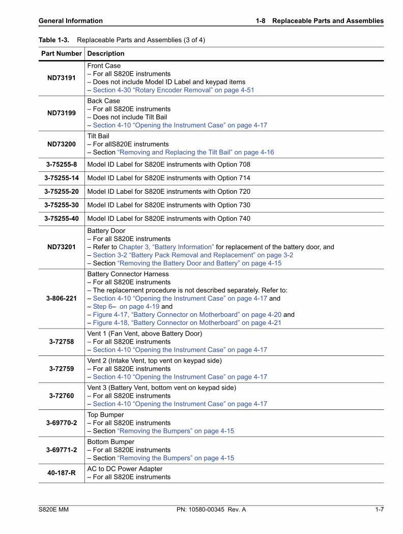
Table 1-3 summarizes the available replaceable parts and assemblies with links to Chapter 4, “Assembly Removal and Replacement” detailed procedures.
Table 1-3. Replaceable Parts and Assemblies (1 of 4)
Part Number Description
ND80107Main/VNA PCB Assembly for S820E instruments with Option 708– LCD Display not included– Section 4-12 “Main/VNA PCB and Connector Panel Removal” on page 4-23
ND80108Main/VNA PCB Assembly for S820E instruments with Option 714– LCD Display not included– Section 4-12 “Main/VNA PCB and Connector Panel Removal” on page 4-23
ND80109Main/VNA PCB Assembly for S820E instruments with Option 720– LCD Display not included– Section 4-12 “Main/VNA PCB and Connector Panel Removal” on page 4-23
ND80110Main/VNA PCB Assembly for S820E instruments with Option 730– LCD Display not included– Section 4-12 “Main/VNA PCB and Connector Panel Removal” on page 4-23
ND80111Main/VNA PCB Assembly for S820E instruments with Option 740– LCD Display not included– Section 4-12 “Main/VNA PCB and Connector Panel Removal” on page 4-23
3-75251Dual Sampler Assembly for all S820E instruments with Options 714, 720, 730, and 740– Section 4-20 “Dual Sampler Assembly Removal” on page 4-36
72005-320 GHz Microwave Source and Transfer Switch Assembly for S820E instruments with Option 714 or 720– Section 4-18 “Microwave Module Removal” on page 4-34
72005-440 GHz Microwave Source and Transfer Switch Assembly for S820E instruments with Option 730 or 740– Section 4-18 “Microwave Module Removal” on page 4-34
3-68175N female Test Port Adapter– For all S820E instruments with Options 708 or 714– Section 4-16 “Port Connector Removal” on page 4-31
3-75651Ruggedized K male Test Port Adapter– For all S820E instruments with Options 720, 730, or 740– Section 4-16 “Port Connector Removal” on page 4-31
3-75261-1Cable, BNC(f) to MCX(m), 254 mm, External Trigger In– For all S820E instruments– Section 4-14 “Connector Panel Removal” on page 4-27
3-75261-2Cable, BNC(f) to MCX(m), 127 mm, External Reference In– For all S820E instruments– Section 4-14 “Connector Panel Removal” on page 4-27
3-15-165LCD Display– For all S820E instruments– Section 4-24 “LCD Assembly Removal” on page 4-42

1-8 Replaceable Parts and Assemblies General Information
1-6 PN: 10580-00345 Rev. A S820E MM
ND73867Touch Screen with Gasket– For all S820E instruments– Section 4-28 “Touch Screen Removal” on page 4-49
3-72621-4Cable, LCD Display to Main/VNA PCB Assembly, 7 cm, Black– For all S820E instruments– Section 4-24 “LCD Assembly Removal” on page 4-42
3-72773Keypad Rubber Membrane– For all S820E instruments– Section 4-26 “Keypad PCB Removal” on page 4-46
ND80115Keypad PCB– For all S820E instruments– Section 4-26 “Keypad PCB Removal” on page 4-46
3-905-2744Keypad PCB Screw– For all S820E instruments– Section 4-26 “Keypad PCB Removal” on page 4-46
3-72767Keypad PCB Washer– For all S820E instruments– Section 4-26 “Keypad PCB Removal” on page 4-46
3-71625-1Cable, Keypad PCB to LCD Display Backlight– For all S820E instruments– Section 4-26 “Keypad PCB Removal” on page 4-46
3-74842-3Cable, Keypad PCB to Main/VNA PCB Assembly, 15 cm, white– For allS820E instruments– Section 4-26 “Keypad PCB Removal” on page 4-46
3-410-103
Rotary Encoder – For all S820E instruments– Does not include the Rotary Knob 3-61360-2– Section 4-30 “Rotary Encoder Removal” on page 4-51
3-61360-2
Encoder Rotary Knob (excluding encoder)– For all S820E instruments– Does not include the Rotary Encoder 3-410-101– Section “Removing and Replacing the Rotary Knob” on page 4-16
3-72779Fan Assembly– For all S820E instruments– Section 4-22 “Fan Assembly Removal” on page 4-38
3-790-727Fan Mount– For all S820E instruments– Section 4-22 “Fan Assembly Removal” on page 4-38
ND73192
Speaker Assembly– For all S820E instrumentsThe replacement procedure is not described separately. The speaker is attached to the Front Case. Refer to:
– Section 4-10 “Opening the Instrument Case” on page 4-17Remove components until speaker is exposed, as in: – Section 4-30 “Rotary Encoder Removal” on page 4-51
Table 1-3. Replaceable Parts and Assemblies (2 of 4)
Part Number Description
General Information 1-8 Replaceable Parts and Assemblies
S820E MM PN: 10580-00345 Rev. A 1-7
ND73191
Front Case– For all S820E instruments– Does not include Model ID Label and keypad items– Section 4-30 “Rotary Encoder Removal” on page 4-51
ND73199
Back Case– For all S820E instruments– Does not include Tilt Bail– Section 4-10 “Opening the Instrument Case” on page 4-17
ND73200Tilt Bail– For allS820E instruments– Section “Removing and Replacing the Tilt Bail” on page 4-16
3-75255-8 Model ID Label for S820E instruments with Option 708
3-75255-14 Model ID Label for S820E instruments with Option 714
3-75255-20 Model ID Label for S820E instruments with Option 720
3-75255-30 Model ID Label for S820E instruments with Option 730
3-75255-40 Model ID Label for S820E instruments with Option 740
ND73201
Battery Door– For all S820E instruments– Refer to Chapter 3, “Battery Information” for replacement of the battery door, and – Section 3-2 “Battery Pack Removal and Replacement” on page 3-2– Section “Removing the Battery Door and Battery” on page 4-15
3-806-221
Battery Connector Harness– For all S820E instruments– The replacement procedure is not described separately. Refer to:– Section 4-10 “Opening the Instrument Case” on page 4-17 and – Step 6– on page 4-19 and – Figure 4-17, “Battery Connector on Motherboard” on page 4-20 and – Figure 4-18, “Battery Connector on Motherboard” on page 4-21
3-72758Vent 1 (Fan Vent, above Battery Door)– For all S820E instruments– Section 4-10 “Opening the Instrument Case” on page 4-17
3-72759Vent 2 (Intake Vent, top vent on keypad side)– For all S820E instruments– Section 4-10 “Opening the Instrument Case” on page 4-17
3-72760Vent 3 (Battery Vent, bottom vent on keypad side)– For all S820E instruments– Section 4-10 “Opening the Instrument Case” on page 4-17
3-69770-2Top Bumper– For all S820E instruments– Section “Removing the Bumpers” on page 4-15
3-69771-2Bottom Bumper– For all S820E instruments– Section “Removing the Bumpers” on page 4-15
40-187-RAC to DC Power Adapter– For all S820E instruments
Table 1-3. Replaceable Parts and Assemblies (3 of 4)
Part Number Description

1-8 Replaceable Parts and Assemblies General Information
1-8 PN: 10580-00345 Rev. A S820E MM
633-75Rechargeable high capacity battery, Lithium-Ion– For allS820E instruments
2000-1654-RSoft Carrying Case– For all S820E instruments
806-141Automotive 12 Volt DC Adapter– For all S820E instruments
3-2000-1498USB Type 2 A to Mini B Cable, 3 meters (10 feet)– For all S820E instruments
2000-1371-RCategory 5 (Cat5) Ethernet Cable– For all S820E instruments
Table 1-3. Replaceable Parts and Assemblies (4 of 4)
Part Number Description

S820E MM PN: 10580-00345 Rev. A 2-1
Chapter 2 — Performance Verification
2-1 IntroductionThis chapter provides procedures to be used to verify the performance of Site Master S820E.
The procedures consists of two parts:
• Manual Performance Test
• Frequency Accuracy Verification
• Automated Performance Tests
• S-parameters Measurements Verification
• Transmission Dynamic Range Verification
• Transmission High Level Noise Verification
2-2 Manual Performance Test − Frequency Accuracy Verification This manual performance test procedure is used to verify the CW frequency accuracy of the vector network analyzer in the Site Master S820E. Measurement calibration of the VNA is not required for this test.
Equipment Required
• Frequency Reference, Symmetricom RubiSource T&M
• Frequency Counter, Anritsu Model MF2412B or MF2412C
• RF Coaxial Cable, Anritsu Model 3670K50-2
• N male to K female Adapter, Anritsu Model 34NKF50
• N male to K male Adapter, Anritsu Model 34NK50 (For units with Options 708 or 714)
• BNC male to BNC male coaxial cable, Anritsu part number 2000-1627-R
Procedure
1. Turn on the Frequency Reference.
2. Install a BNC male to BNC male cable between the 10 MHz Output of the Frequency Reference and the Reference Input of the MS241xx Frequency Counter.
3. On the Frequency Counter, press the Preset key.
4. Turn on the Site Master S820E.
5. On the Site Master, press the Shift key, the Preset (1) key, and then the Preset soft key to reset the instrument to the default starting conditions.
6. Press the Freq/Dist soft key on the bottom of the LCD display, and then press the Start Frequency (F1) soft key.
7. Enter 1 and press the GHz soft key to set the Start Frequency to 1 GHz.
8. Press the Stop Frequency (F2) soft key.
9. Enter 1 and press the GHz soft key to set the Stop Frequency to 1 GHz.
10. Attach the RF cable from the Site Master Port 1 to the RF Input 1 connector on the Frequency Counter.
Note Before continuing, allow a 30-minute warm up for the internal circuitry to stabilize.
2-2 Manual Performance Test − Frequency Accuracy Verification Performance Verification
2-2 PN: 10580-00345 Rev. A S820E MM
11. Verify that the Frequency Counter reading is 1 GHz ± 5 kHz.
12. Record the Frequency Counter reading in Hz to the test record in “VNA Frequency Accuracy” on page A-2 of Appendix A.

Performance Verification 2-3 Automated Performance Tests
S820E MM PN: 10580-00345 Rev. A 2-3
2-3 Automated Performance Tests The automated performance tests consists of the following:
• S-parameter Measurements Verification
• Transmission Dynamic Range Verification
• Transmission High Level Noise Verification
These tests are automated using the Site Master S820E Performance Verification Software, part number 2300-555, in conjunction with the equipment listed in Table 2-1, “Equipment Required for Automated Tests.
The software guides the user to perform a measurement calibration on the Site Master S820E using the appropriate calibration tees and then proceeds to guide the user through the steps for S-parameter Measurements Verification, Transmission Dynamic Range Verification, and Transmission High Level Noise Verification.
Pass/Fail status of the measurements is displayed on the computer. The software can also provide hardcopy (printout) of the test reports which include the measured data, the measurement uncertainties, and the Pass/Fail status.
Test Sequence
The user can run all the automated tests in a consecutive fashion or run individual test selectively.
If all are selected, the test sequence is:
• VNA Calibration
• Airline (DAT) Measurements
• Airline (UNC) Uncertainty Computation [Pass/Fail Determination]
• Beatty Airline (DAT) Measurements
• Beatty Airline (UNC) Uncertainty Computation
• 20 dB Offset (Pad) (DAT) Measurements
• 20 dB Offset (Pad) (UNC) Uncertainty Computation
• 50 dB Offset (Pad) (DAT) Measurements
• 50 dB Offset (Pad) (UNC) Uncertainty Computation
• Transmission Dynamic Range Measurements
• Transmission High Level Noise Measurements
Test Reports
Each test generates data report in TXT file format. The data report files can be viewed and printed either using the software built-in “Print” function or other software applications, such as NotePad or other word processors. The data report files are:
• 20DB OFFSET (UNC) #VER.TXT
• 50DB OFFSET (UNC) #VER.TXT
• AIRLINE (UNC) #VER.TXT
• BEATTY (UNC) #VER.TXT
• TRANSMISSION DYNAMIC RANGE.TXT
• TRANSMISSION HIGH LEVEL NOISE.TXT
NoteThe Site Master S820E Performance Verification Software should already be installed to the PC controller prior to performing the automated performance tests described in this chapter.

2-3 Automated Performance Tests Performance Verification
2-4 PN: 10580-00345 Rev. A S820E MM
These files can be found in the following folder on the hard drive of the PC Controller:
C:\Anritsu HH Analyzer Verification\VNA_Reports\S820E_xxxxxxx
[where xxxxxxx is the serial number of the S820E being tested]
Equipment Required for Automated Tests
Table 2-1. Equipment Required for Automated Tests
Equipment Critical Specification Recommended
Manufacturer/Model
Open/Short/Load(for Option 708)
Frequency: DC to 8 GHzConnector: N(m)
Anritsu Model OSLN50A-8, OSLN50A-18, TOSLN50A-8 or TOSLN50A-18
Open/Short/Load(for Option 708)
Frequency: DC to 8 GHzConnector: N(f)
Anritsu Model OSLNF50A-8, OSLNF50A-18, TOSLNF50A-8 or TOSLNF50A-18
Open/Short/Load(for Options 708 or 714)
Frequency: DC to 18 GHzConnector: N(m)
Anritsu Model OSLN50A-18 or TOSLN50A-18
Open/Short/Load(for Options 708 or 714)
Frequency: DC to 18 GHzConnector: N(f)
Anritsu Model OSLNF50A-18 or TOSLNF50A-18
Verification Kit(for Options 708 or 714)
Connector: N Type Anritsu Model 3663-1
Adapter(for Options 708 or 714)
Frequency: DC to 18 GHzConnector: N(m) to K(m)
Anritsu Model 34NK50
Adapter(for Options 708 or 714)
Frequency: DC to 18 GHzConnector: N(m) to K(f)
Anritsu Model 34NKF50
Torque Wrench(for Options 708 or 714)
3/4 in. (0.75 in.) Open End Wrench12 lbf·in (1.35 N·m)
Anritsu Model 01-200
Open/Short/Load(for Option 720)
Frequency: DC to 20 GHzConnector: K(m)
Anritsu Model TOSLK50A-20 or TOSLK50A-40
Open/Short/Load(for Option 720)
Frequency: DC to 20 GHzConnector: K(f)
Anritsu Model TOSLKF50A-20 or TOSLKF50A-40
Open/Short/Load(for Options 720, 730, or 740)
Frequency: DC to 40 GHzConnector: K(m)
Anritsu Model TOSLK50A-40
Open/Short/Load(for Options 720, 730, or 740)
Frequency: DC to 40 GHzConnector: K(f)
Anritsu Model TOSLKF50A-40 or 28KF50
Verification Kit(for Option 720, 730, or 740)
Connector: K Type Anritsu Model 3668-1
Adapter(for Option 720, 730, or 740)
Frequency: DC to 40 GHzConnector: K(m) to K(f)
Anritsu Model 33KKF50B
Adapter(for Option 720, 730, or 740)
Frequency: DC to 40 GHzConnector: K(f) to K(f)
Anritsu Model 33KFKF50B
Torque Wrench(for Option 720, 730, or 740)
5/16 in. (0.325 in.)Open End Wrench8 lbf· in (0.90 N·m)
Anritsu Model 01-201
RF Coaxial CableFrequency: DC to 40 GHzImpedance: 50 ohmConnector: K(f) to K(m)
Anritsu Model 3670K50-2

Performance Verification 2-3 Automated Performance Tests
S820E MM PN: 10580-00345 Rev. A 2-5
Interface CableUSB: USB A to USB mini BEthernet: RJ48, cross-over, Cat.5EEthernet: RJ48, Cat.5E
Anritsu Part Number 3-2000-1498Anritsu Part Number 3-806-152Anritsu Part Number 2000-1371-R
Connector Wrench Anritsu Part Number 01-204
Personal Computer
Operating System: Windows 7Interface: Ethernet, RJ-48Software: National Instruments VISA version 4.4.1 or later
Any
System Verification Software Anritsu Part Number 2300-555
Table 2-1. Equipment Required for Automated Tests
Equipment Critical Specification Recommended
Manufacturer/Model

2-3 Automated Performance Tests Performance Verification
2-6 PN: 10580-00345 Rev. A S820E MM
S-parameter Measurements Verification Test
This test verifies S-parameter measurement capabilities of the Site Master S820E, calibration tees, test port cable, and any required adapters as a system by analyzing the measurement of artifacts that are traceable to national standards laboratories.
The 2300-555 Performance Verification software guides you to perform a measurement calibration on the Site Master S820E by using the appropriate calibration tees, to measure the S-parameters of the impedance transfer standards in the verification kit, and to verify that the measured values are within the specified measurement uncertainty limits.
The impedance transfer standards that are contained in the Anritsu 3663-1 (N connector) or 3668-1 (K connector) verification kit are:
• 50 ohm Air Line Standard
• 25 ohm Mismatch (Beatty) Standard
• 20 dB Attenuation Standard
• 50 dB Attenuation Standard
The devices in the verification kit are selected based on their ability to stress the envelope of possible measurement parameters while still providing a very stable and repeatable behavior. The key attribute of the devices is that of long term stability.
The quality of the verification result is dependent on the degree of care taken by the user in maintaining, calibrating, and using the system. The most critical factors are:
• The stability and quality of the devices in the calibration tee and the verification kit.
• The condition of the VNA test port connectors and test port cables.
• The pin depths of all connectors.
• The proper torquing of connections.
Special Precaution
When performing the procedures, observe the following precautions:
• Minimize vibration and movement of the system, attached components, and test cable.
• Clean and check the pin depth and condition of all adapters, test port cables, calibration components, and impedance transfer standards.
• Pre-shape the test cable so as to minimize its movement during calibration and measurement activities.
If Verification Fails
If the verification fails, then check the quality, cleanliness, and installation methods for the calibration and verification components. Specifically, check:
• The VNA test port connectors
• The calibration tee
• The impedance transfer standards
• The test port cables, for damage and cleanliness
• The test port cables, for proper connection and torquing
• The test port cables, for phase stability
These are the most common causes for verification failures.
Caution The use of non-Anritsu calibration tees or verification kits is not supported.

Performance Verification 2-3 Automated Performance Tests
S820E MM PN: 10580-00345 Rev. A 2-7
Transmission Dynamic Range Verification
This test verifies the transmission dynamic range performance of the VNA receiver in the Site Master S820E. It is performed with loads connected to Port 1 and the open end of the through cable from Port 2 after a measurement calibration has been performed.
Transmission High Level Noise Verification
This test verifies the high level noise (trace noise) performance of the VNA receiver in the Site Master S820E. This is a measure of the scatter of data when measuring a high level signal (transmission through a short transmission line). The test is performed with the through cable from Port 2 connected to Port 1 after a measurement calibration has been performed.
Automated Test Procedure
1. Turn on power to the PC controller and the Site Master S820E.
2. Use a USB A to USB Mini B cable to connect the mini USB port of the S820E to the USB port of the PC Controller..
3. For units with female N connector test ports:
a. Install the 34NK50 and 34NKF50 Adapters to the 3670K50-2 Through Cable. Use torque wrench to tighten the K connectors to insure that the connections do not work themselves loose during the test.
b. Install the Through Cable with the Adapter to Port 2 of the Site Master.
4. For units with male K connector test ports:
a. Install the 3670K50-2 Through Cable to Port 2 of the Site Master.
b. Install the 33KK50B Adapter to the open end of the cable.
c. Install the 33KFKF50B Adapter to Port 1 of the Site Master.
5. Run the Site Master Verification software on the PC and select Verify System.
6. Verify that the PC controller is communicating with the Site Master.
7. Insert the USB flash drive that is supplied with the verification kit to an available USB port on the PC controller. Set the data location of the verification software to the USB flash drive when prompted.
8. Follow the directions that are displayed on the computer to perform calibration with the appropriate calibration kit.
9. Follow the directions on the computer to perform measurements of the four impedance transfer standards of the appropriate verification kit.
10. Follow the directions on the computer to perform the transmission dynamic range measurements.
Note
Alternatively, use a Cat5-E Ethernet cable to connect the Site Master to a Local Area Network port that is close to the PC controller. Or use a Cat5-E Ethernet Crossover cable to connect the Site Master directly to the PC Controller Ethernet port. Refer to the S820E User Guide, PN 10580-00343, for setup procedures.
CautionUse an appropriate torque wrench to insure proper connection of calibration devices during calibration.
CautionUse an appropriate torque wrench to insure proper connection of verification standard devices prior to starting verification measurements.

2-3 Automated Performance Tests Performance Verification
2-8 PN: 10580-00345 Rev. A S820E MM
11. Follow the directions on the computer to perform the transmission high level noise measurements.
12. After all tests have been completed, print the test results and attach the printouts to the test record in Appendix A, “S820E Site Master Test Record”.

S820E MM PN: 10580-00345 Rev. A 3-1
Chapter 3 — Battery Information
3-1 Introduction This chapter describes battery information for Site Master Model S820E.
NoteSome of the procedures in this section are generic, and apply to many similar instruments. Photos and illustrations are representative and may show instruments other than the S820E.

3-2 Battery Pack Removal and Replacement Battery Information
3-2 PN: 10580-00345 Rev. A S820E MM
3-2 Battery Pack Removal and Replacement This section provides instructions for the removing and replacing the battery pack.
1. With the instrument standing upright on its base and standing on a stable surface, locate the battery access door, as illustrated in Figure 3-1.
Figure 3-1. Battery Access Door

Battery Information 3-2 Battery Pack Removal and Replacement
S820E MM PN: 10580-00345 Rev. A 3-3
2. Place a finger on the actuator in the recess at the top of the battery access door and press downward toward the bottom of the instrument and also outward. The door must be moved against spring pressure in order to release the upper catch.
3. Remove the battery access door.
4. With the battery access door completely removed, grasp the flexible handle of the battery and pull the battery straight out of the instrument (refer to Figure 3-2).
5. Replacement is the opposite of removal. Note the orientation of the battery contacts (refer to Figure 3-3 on page 3-4), and be sure to insert the new battery with the contacts facing the bottom of the instrument.
Figure 3-2. Battery Insertion and Removal

3-2 Battery Pack Removal and Replacement Battery Information
3-4 PN: 10580-00345 Rev. A S820E MM
Battery Pack Information
The following information relates to the care and handling of the Anritsu 633-75 battery pack and Lithium-Ion batteries in general.
• The 633-75 battery pack that is supplied with your instrument may need charging before use. Before using the Site Master, the internal battery may be charged in the Site Master, using either the AC-DC Adapter (40-187-R) or the 12 Volt DC adapter (806-141), or may be charged separately in the optional Dual Battery Charger (2000-1374).
• Use only Anritsu approved battery packs. Some non-approved battery packs will fit into the Site Master, but are electrically incompatible and will not charge correctly.
• Recharge the battery only in the Site Master or in an Anritsu approved charger.
• When the Site Master or the charger is not in use, disconnect it from the power source.
• Do not charge batteries for longer than 24 hours. Overcharging may shorten battery life.
• If left unused, a fully charged battery will discharge itself over time.
• Temperature extremes affect the ability of the battery to charge. Allow the battery to cool down or warm up as necessary before use or charging.
• Discharge the battery from time to time in order to improve battery performance and battery life.
• The battery can be charged and discharged hundreds of times, but it will eventually wear out.
• The battery may need to be replaced when the operating time between chargings becomes noticeably shorter than normal.
• Never use a damaged or worn out charger or battery.
• Storing the battery in extremely hot or cold places will reduce the capacity and lifetime of the battery.
• Never short-circuit the battery terminals.
• Do not drop, mutilate, or attempt to disassemble the battery.
• Do not dispose of batteries in a fire!
• Batteries must be recycled or disposed of properly. Do not place batteries in household garbage.
• Always use the battery for its intended purpose only.
Figure 3-3. Battery Contacts
BatteryContacts

S820E MM PN: 10580-00345 Rev. A 4-1
Chapter 4 — Assembly Removal and Replacement
4-1 IntroductionThis chapter describes the removal and replacement procedures for the various assemblies. Illustrations (drawings or photographs) in this manual may differ slightly from the instrument that you are servicing, but the basic removal and replacement functions will remain as specified. The illustrations are meant to provide assistance with identifying parts and their locations.
4-2 Electrostatic Discharge Prevention An ESD safe work area and proper ESD handling procedures that conform to ANSI/ESD S20.20-1999 or ANSI/ESD S20.20-2007 is mandatory to avoid ESD damage when handling subassemblies or components found in the S820E Microwave Site Master.
4-3 Real Time Clock (RTC) Battery
4-4 Replaceable Parts, Assemblies, and Accessories To ensure that the correct options are provided on the replacement assembly when ordering a Main PCB Assembly, all options that are installed on your instrument must be declared on the order. The installed options are listed on a label on the top of the S820E and can also be viewed in the System/Status display. For a list of replaceable parts, refer to Table 1-3, “Replaceable Parts and Assemblies” on page 1-5.
WarningAll electronic devices, components, and instruments can be damaged by electrostatic discharge. It is important to take preventative measures to protect the instrument and its internal subassemblies from electrostatic discharge.
NoteThe Real Time Clock (RTC) battery is not field replaceable. The instrument must be returned to the factory for service.

4-5 Instrument Case for Site Master S820E Assembly Removal and Replacement
4-2 PN: 10580-00345 Rev. A S820E MM
4-5 Instrument Case for Site Master S820E
Front and Back .
Figure 4-1. Case Front and Rear

Assembly Removal and Replacement 4-5 Instrument Case for Site Master S820E
S820E MM PN: 10580-00345 Rev. A 4-3
Case Outer Components
Figure 4-2. Case and Bumpers

4-5 Instrument Case for Site Master S820E Assembly Removal and Replacement
4-4 PN: 10580-00345 Rev. A S820E MM
Opening the Case
The bumpers are removed to expose the six screws that secure the front and back case when closed.
Figure 4-3. Location of Six Screws that Secure Case Back to Case Front

Assembly Removal and Replacement 4-5 Instrument Case for Site Master S820E
S820E MM PN: 10580-00345 Rev. A 4-5
The case back is held by 6 screws, as shown in Figure 4-4. When the back case is clear of all parts in the front case, the back is folded open to allow disconnecting the battery cable (item 1).
1. The battery connection to the Main PCB
Figure 4-4. Opening the Case, Removing the Back
1

4-5 Instrument Case for Site Master S820E Assembly Removal and Replacement
4-6 PN: 10580-00345 Rev. A S820E MM
Basic Case Parts
The Case Front includes the Keypad, Touch Screen, LCD, and Fan.
The Case Back includes the Battery Compartment and its Door and the Tilt Bail.
Figure 4-5. Perspective View of Case Parts (Case bottom is Facing Upward)

Assembly Removal and Replacement 4-5 Instrument Case for Site Master S820E
S820E MM PN: 10580-00345 Rev. A 4-7
Front Panel Components
Figure 4-6. Front Panel Components
1. Keypad PCB
2. Keypad Rubber Membrane
3. Rotary Encoder
4. Knob for Rotary Encoder
5. Case Bezel
6. Gasket (between touchscreen and case bezel)
1 32
5
4
6

4-5 Instrument Case for Site Master S820E Assembly Removal and Replacement
4-8 PN: 10580-00345 Rev. A S820E MM
Back Panel Components
The fan, touch screen, and keypad are front case components.
Figure 4-7. Back Panel Components
1. Tilt Bail
2. Door to Battery Compartment
3. Battery Location
4. Ventilation Grill for Fan Inlet
5. Fan Location
6. Touchscreen
7. Keypad
1
3
7
2
54
6

Assembly Removal and Replacement 4-6 Test Panel Connectors
S820E MM PN: 10580-00345 Rev. A 4-9
4-6 Test Panel Connectors
1. Port 1, Type N, Female (Options 0708, 0714) or Ruggedized K, Male (Options 0720, 0730, 0740)
50 ohm impedance. Maximum input is +23 dBm at ±50 VDC. Torque to 12 lbf·in or 1.4 N·m (N connector) or to 8 lbf·in or 0.90 N·m (K connector).
2. Port 2, Type N, Female (Options 0708, 0714) or Ruggedized K, Male (Options 0720, 0730, 0740)
50 ohm impedance. Maximum input is +23 dBm at ±50 VDC. Torque to 12 lbf·in or 1.4 N·m (N connector) or to 8 lbf·in or 0.90 N·m (K connector).
3. External Trigger In, Type BNC(f), 50 ohm
This function is currently not enabled, but it will be enabled via a future firmware update.
Maximum input is +5 VDC.
4. External Reference In, Type BNC(f), 50 ohm
Auto-detects a 10 MHz external reference. When active the Measurement Setting for Freq Ref will display “External”. Maximum input is +10 dBm.
5. USB Interface – Type Mini-B (version 2.0)
The USB 2.0 Mini-B connector can be used to connect the Site Master directly to a PC.
6. External Power, 5.5 mm Barrel Connector
The external power connector is used to power the instrument and for battery charging. Input is 11 VDC to 14 VDC at up to 4.0 A. When using the AC-DC Adapter, always use a grounded three-wire power cable that is connected to a three-wire power line outlet. Failure to use properly grounded electrical equipment may result in severe or potentially fatal injury.
7. USB Interface – Type A (version 2.0)
The Site Master has two Type A USB 2.0 connectors that accept USB Flash Memory devices for storing or transferring measurements, setups, and screen shots. USB sensors that are used for 2-port cable loss mea-surements and high accuracy power meter measurements and certain USB peripheral devices (such as a USB GPS module, USB mouse, or USB keyboard) may also be supported.
8. RJ45 connector (10/100 Ethernet)
Used to connect the Site Master to a local area network. When the instrument is connected to a network, the instrument will obtain an IP address via DHCP.
9. Headset Jack
The jack accepts a 3.5 mm 3-wire miniature phone plug such as those commonly used with cellular tele-phones. The speaker output is diverted to the headphone when the headphone is plugged into this jack.
Figure 4-8. S820E Test Panel Connectors
1 2 3 4
67
5
89

4-7 Internal Anatomy of the Site Master S820E Assembly Removal and Replacement
4-10 PN: 10580-00345 Rev. A S820E MM
4-7 Internal Anatomy of the Site Master S820E
Case Assembly Components with Complete PCB
Figure 4-9. Case Assembly Components with Case Back Removed – Complete PCB

Assembly Removal and Replacement 4-7 Internal Anatomy of the Site Master S820E
S820E MM PN: 10580-00345 Rev. A 4-11
Case Assembly Components with Motherboard PCB
Motherboard and Connector Panel
Figure 4-10. Case Assembly Components with Case Back Removed – 8 GHz Motherboard PCB

4-7 Internal Anatomy of the Site Master S820E Assembly Removal and Replacement
4-12 PN: 10580-00345 Rev. A S820E MM
Motherboard and Connector Panel for Option S820E-0708
Figure 4-11. Main PCB and Connector Panel for 8 GHz Option

Assembly Removal and Replacement 4-7 Internal Anatomy of the Site Master S820E
S820E MM PN: 10580-00345 Rev. A 4-13
Motherboard and Connector Panel for Higher Frequency Options
Figure 4-12. Main PCB and Connector Panel (all except 8 GHz option)

4-8 Disassembly Sequence Overview Assembly Removal and Replacement
4-14 PN: 10580-00345 Rev. A S820E MM
4-8 Disassembly Sequence Overview Except for replacing the rotary knob, bumpers, battery door, and tilt bail, the case must be opened for all maintenance operations. Part numbers for all replaceable parts are found in Table 1-3, “Replaceable Parts and Assemblies” on page 1-5.
Removal and Replacement Instructions
The removal and replacement instructions are described in the following sections:
• Section 4-9 “Replacements That Do Not Require Opening the Case” on page 4-15
• Section 4-10 “Opening the Instrument Case” on page 4-17
• Section 4-11 “Closing the Case” on page 4-22
• Section 4-12 “Main/VNA PCB and Connector Panel Removal” on page 4-23
• Section 4-14 “Connector Panel Removal” on page 4-27
• Section 4-16 “Port Connector Removal” on page 4-31
• Section 4-18 “Microwave Module Removal” on page 4-34
• Section 4-20 “Dual Sampler Assembly Removal” on page 4-36
• Section 4-22 “Fan Assembly Removal” on page 4-38
• Section 4-24 “LCD Assembly Removal” on page 4-42
• Section 4-26 “Keypad PCB Removal” on page 4-46
• Section 4-28 “Touch Screen Removal” on page 4-49
• Section 4-30 “Rotary Encoder Removal” on page 4-51
• Section 4-32 “Speaker Removal” on page 4-52
Caution
Only qualified personnel should open the case and replace internal assemblies. Assemblies that are shown in the replaceable parts list are typically the only items that may be replaced.
Because they are highly fragile, items that must be soldered may not be replaced without specialized training.
Removing RF shields from PC boards, or adjusting screws on or near the shields may detune sensitive RF circuits and will result in degraded instrument performance.
All work must be performed in a static-safe work area.
NoteBefore opening the case, Anritsu Company strongly recommends that all internally-saved files be saved to a PC, or that they be copied to an external USB flash drive. In the event that the Main/VNA PCB needs to be replaced, this recommended action will prevent permanent loss of these files.

Assembly Removal and Replacement 4-9 Replacements That Do Not Require Opening the Case
S820E MM PN: 10580-00345 Rev. A 4-15
4-9 Replacements That Do Not Require Opening the Case This section provides instructions for replacing parts without opening the Site Master case. The part numbers are listed in Table 1-3, “Replaceable Parts and Assemblies” on page 1-5.
Removing the Bumpers
Remove the top and bottom bumpers (Figure 4-13) to expose the screw holes on the back case of the instrument (Figure 4-3 on page 4-4). Pull on a corner of each rubber bumper to stretch and disengage the rubber from the case.
Removing the Battery Door and Battery
Removal of the battery door and battery are described in Section 3-2 “Battery Pack Removal and Replacement” on page 3-2.
Figure 4-13. Remove the Bumpers

4-9 Replacements That Do Not Require Opening the Case Assembly Removal and Replacement
4-16 PN: 10580-00345 Rev. A S820E MM
Removing and Replacing the Rotary Knob
This procedure covers removing and replacing the Rotary Knob. The case does not need to be opened for this procedure. Note that this part does not include the Rotary Encoder. To replace the Rotary Encoder, refer to Section 4-30 “Rotary Encoder Removal” on page 4-51.
1. Use a medium flat blade screwdriver and a small protective piece of rubber (as a fulcrum) to remove the Rotary Knob.
2. Position the rubber piece next to the knob, and slide in the screwdriver between the knob and the case.
3. Gentle lever the knob up and off of its mounting shaft.
4. Position the replacement knob over the shaft and press into place. No specific orientation is required for the knob.
Removing and Replacing the Tilt Bail
Four screws secure the tilt bail to the back (bottom) case of the Site Master. Remove these four screws to separate the tilt bail from the bottom case. When replacing the tilt bail, tighten these screws to 6.2 lbf in (0.70 N · m).
Figure 4-14. Remove the Four Screws to Replace the Tilt Bail

Assembly Removal and Replacement 4-10 Opening the Instrument Case
S820E MM PN: 10580-00345 Rev. A 4-17
4-10 Opening the Instrument Case This procedure provides instructions for opening the Site Master case. With the case opened, the internal assemblies can be removed and replaced, as described in the rest of this chapter.
Procedure
1. Remove the battery door and battery as shown in Section 3-2 “Battery Pack Removal and Replacement” on page 3-2.
2. Remove the top and bottom bumpers (Figure 4-15 on page 4-18) to expose the screw holes on the back of the unit. Pull on a corner of each rubber bumper to stretch and disengage the rubber from the case.
Caution
Electrostatic Discharge (ESD) can damage the highly sensitive circuits in the instrument.
Repair of damage that is found to be caused by electrostatic discharge is not covered under warranty.
The Site Master contains components that can be easily damaged by electrostatic discharge (ESD). An ESD safe work area and proper ESD handling procedures that conform to ANSI/ESD S20.20-1999 or ANSI/ESD S20.20-2007 are mandatory to avoid ESD damage when handling sub-assemblies or components that are found in these instruments.

4-10 Opening the Instrument Case Assembly Removal and Replacement
4-18 PN: 10580-00345 Rev. A S820E MM
3. Place the Site Master face down on a stable work surface that will not scratch the display.
Figure 4-15. Removal of Bumpers and Rotary Knob

Assembly Removal and Replacement 4-10 Opening the Instrument Case
S820E MM PN: 10580-00345 Rev. A 4-19
4. Use a Phillips screwdriver to remove the six screws securing the two halves of the case together. The instrument that is shown in Figure 4-16 is not a Site Master, but the case is the same.
5. As you begin to separate the two halves of the case, carefully lift up a small amount first on the right side of the case (as viewed from the back – in other words, the side opposite the keypad when viewed from the front).
Then lift the entire case back (bottom) away from the case front just far enough to clear the internal parts and the vent grills.
Then open the case as if opening a book, laying the back to the left, hinging the two case halves on the one cable (battery power) that links the two case halves together. Take care to avoid damage to the cable or its connector.
6. With the Site Master back case laying flat beside the front case, remove the battery cable connector (item 1 in Figure 4-17 and Figure 4-18) from the Mother Board. The two halves of the case may then be separated.
Figure 4-16. Remove the Six Screws

4-10 Opening the Instrument Case Assembly Removal and Replacement
4-20 PN: 10580-00345 Rev. A S820E MM
1. Battery Connector
Figure 4-17. Battery Connector on Motherboard
1

Assembly Removal and Replacement 4-10 Opening the Instrument Case
S820E MM PN: 10580-00345 Rev. A 4-21
1. Battery Connector
Figure 4-18. Battery Connector on Motherboard
1

4-11 Closing the Case Assembly Removal and Replacement
4-22 PN: 10580-00345 Rev. A S820E MM
4-11 Closing the Case Closing the case is the reverse of opening.
1. With the Case Front Assembly face down on a clean, stable work surface that will not scratch the front panel, place the Case Back Assembly beside the case front assembly, as when opening the case (refer to Step 5 on page 4-19 in “Opening the Instrument Case”).
2. Connect the battery cable to the Mother board and close the case (see Figure 4-18 on page 4-21 and Figure 4-4 on page 4-5). Tuck excess battery cable behind the battery connector as you fold the case back assembly over the case front assembly, taking care to align the top connector panel into the case grooves, and to align the 3 vents with grooves in the case halves. Ensure that the battery cable is not pinched by the case.
3. Use a Phillips screwdriver to replace the six (6) Pan Head Phillips-head screws that secure the two case halves together. Torque these 6 screws to 6.2 lbf · in (0.70 N · m).
Installing Battery
Refer to Section 3-2 “Battery Pack Removal and Replacement” on page 3-2.
4. Install the Battery.
5. Install the Battery Door.
Restarting the Instrument
6. Restart the instrument.
7. Perform a function check to verify all repairs and part replacements.

Assembly Removal and Replacement 4-12 Main/VNA PCB and Connector Panel Removal
S820E MM PN: 10580-00345 Rev. A 4-23
4-12 Main/VNA PCB and Connector Panel Removal The Main/VNA PCB Assembly includes the top connector panel. This procedure provides instructions for removing the Main/VNA PCB assembly from all S820E Site Masters. Figure 4-19 shows the Main/VNA PCB assembly of Option 714, Option 720, Option 730, and Option 740. Main/VNA PCB Assembly removal from Option 708 is similar. Refer to Table 1-3, “Replaceable Parts and Assemblies” on page 1-5.
The Main/VNA PCB for these higher-frequency options includes two additional components, the Microwave Source and Transfer Switch (item 1 in Figure 4-19) and the Dual Sampler Assembly (item 2 in Figure 4-19).
1. Microwave Source and Transfer Switch Assembly
2. Dual Sampler Assembly
Figure 4-19. Removing PCB from Front Case (Option 714 Shown)
1 2

4-12 Main/VNA PCB and Connector Panel Removal Assembly Removal and Replacement
4-24 PN: 10580-00345 Rev. A S820E MM
Procedure
Refer to Figure 4-20 for component identification.
1. Follow the procedure in Section 4-10 “Opening the Instrument Case” on page 4-17.
2. Disconnect the keypad cable (item 2) from motherboard connector J27 and carefully fold it out the way.
3. Disconnect the LCD cable (item 5) from J18 and carefully fold it out the way.
4. Disconnect the fan cable (item 4) from connector J24 and fold it out of the way.
5. Remove the 4 screws (item 1) holding the PCB assembly to the instrument case.
6. Carefully lift the Main/VNA PCB assembly from the front case, keeping all cables clear.
1. MIAN/VNA PCB mounting screws
2. Keypad PCB cable
3. Fan
4. Fan cable
5. LCD cable
Figure 4-20. 40 GHz Main PCB (in Front Case)
NoteFigure 4-20 Main PCB is from a 40 GHz Site Master (Option 740). The procedure for removal of the PCB and the attached top connector panel is the same for all Site Masters.
2
1 1
1
3
5
4
1

Assembly Removal and Replacement 4-13 Main/VNA PCB Assembly Installation
S820E MM PN: 10580-00345 Rev. A 4-25
4-13 Main/VNA PCB Assembly Installation This procedure provides instructions for installing the Main/VNA PCB assembly (with connector panel). Installation is the reverse of removal. The 8 GHz Option 708 PCB assembly is shown in Figure 4-21. Installing the PCB assembly of other frequency options is similar.
1. Case Front
2. Keypad cable to Main/VNA PCB
3. Connector J27 for keypad cable
4. Main/VNA PCB
5. Top Connector Panel
6. Connector J24 for fan cable
7. Connector J18 for the LCD
8. Fan cable
9. LCD cable
Figure 4-21. Removing 8 GHz PCB Assembly from Front Case.
1
3
9
2
54
8
7
6

4-13 Main/VNA PCB Assembly Installation Assembly Removal and Replacement
4-26 PN: 10580-00345 Rev. A S820E MM
Procedure
Refer to Figure 4-21 for part identification. The front case (item 1) holds the keypad, LCD, Main/VNA PCB (item 4), and the top Connector Panel (item 5). Refer to Table 1-3 on page 1-5 for part numbers of PCB assemblies of the available frequency options. The cable (item 2) from the keypad to the PCB plugs into connector J27 (item 3) on the Main/VNA PCB. The fan cable (item 8) plugs into connector J24 (item 6). The LCD cable (item 9) plugs into connector J18 (item 7).
1. With the Site Master front case face down on a stable work surface that will not scratch the display, gently insert the Main/VNA PCB and connector panel into the front case. Carefully guide the keypad cable (item 2) and the fan and LCD cables (item 8 and item 9) as you install the PCB into the front case.
2. Secure the replacement Main/VNA PCB to the front case with the 4 screws shown as item 1 in Figure 4-20 on page 4-24. Torque these 4 screws to 7.5 lbf · in (0.85 N · m).
3. Connect the LCD cable (item 9) to connector J18 (item 7).
4. Connect the fan cable (item 8) to connector J24 (item 6).
5. Connect the keypad cable (item 2) to connector J27 (item 3).
6. Close the case as described in Section 4-11 “Closing the Case” on page 4-22.

Assembly Removal and Replacement 4-14 Connector Panel Removal
S820E MM PN: 10580-00345 Rev. A 4-27
.4-14 Connector Panel Removal This procedure provides instructions for separating the connector panel from the Main/VNA PCB Assembly.
Figure 4-22. Main PCB and Connector Panel for 8 GHz Option
1. MCX Connector J30
2. MCX Cable for External Trigger In (connects to J34)
3. MCX Cable for External Reference In (connects to J30)
4. U-loop semi-rigid cable for Port 2
1
3
7
8
2
54
6
8

4-14 Connector Panel Removal Assembly Removal and Replacement
4-28 PN: 10580-00345 Rev. A S820E MM
Procedure
1. Follow the procedure in Section 4-10 “Opening the Instrument Case” on page 4-17.
2. Follow the procedure in Section 4-12 “Main/VNA PCB and Connector Panel Removal” on page 4-23.
For 8 GHz Option 708 Main/VNA PCB Assembly
Refer to Figure 4-22 on page 4-27 for items in this procedure.
1. Remove the two U-loop semi-rigid cables between the port connectors and the Main/VNA PCB. Refer to item 4 and item 5.
2. Disconnect the MCX cables of the External Reference In connector (refer to item 3 and item 1) and the External Trigger In connector (refer to item 2 and item 8).
3. Remove the pan head Phillips screw on the top side of the PCB, located nearest to the Port 1 connector. Refer to item 7.
4. Remove the pan head Phillips screw located near the center on the bottom side. Refer to item 6.
5. Carefully separate the connector panel from the motherboard.
For Other Main/VNA PCB Assemblies
Refer to Figure 4-23 on page 4-29 for items in this procedure.
1. Disconnect the MCX cable of the External Reference In connector (refer to item 3 and item 1) and the External Trigger In connector (refer to item 2 and item 8).
2. Remove the pan head Phillips screw on the top side of the PCB, located nearest to the Port 1 connector. Refer to item 7.
3. Remove the pan head Phillips screw located near the center on the bottom side. Refer to item 6.
4. Carefully disconnect the SMA connections between the Dual Sampler Module and the Port connectors. Refer to item 4 and item 5.
5. Carefully separate the connector panel from the motherboard.
5. U-loop semi-rigid cable for Port 1
6. Bracket and pan head Phillips screw
7. Bracket and pan head Phillips screw
8. MCX Connector J34

Assembly Removal and Replacement 4-14 Connector Panel Removal
S820E MM PN: 10580-00345 Rev. A 4-29
Figure 4-23. Main PCB and Connector Panel (all except 8 GHz option)
1. MCX Connector J30
2. MCX Cable for External Trigger In (connects to J34)
3. MCX Cable for External Reference In (connects to J30)
1
3
7
8
254
6
8

4-15 Connector Panel Installation Assembly Removal and Replacement
4-30 PN: 10580-00345 Rev. A S820E MM
4-15 Connector Panel Installation Installation of the connector panel is the reverse of removal. Refer to Table 1-3, “Replaceable Parts and Assemblies” on page 1-5.
1. For Option 714, Option 720, Option 730, and Option 740 assemblies, torque the SMA connectors (at Port 1 and Port 2) to 8.0 lbf · in (0.90 N · m). Refer to item 4 and item 5 in Figure 4-23 on page 4-29.
2. Secure the connector panel to the Main/VNA PCB by tightening the two pan head Phillips screws to a torque of 7.5 lbf · in (0.85 N · m). Refer to item 6 and item 7 in Figure 4-23 on page 4-29, or refer to item 6 and item 7 in Figure 4-22 on page 4-27.
3. For Option 708 assemblies, torque the SMA connectors of the U-loop semi-rigid cables between the port connectors and the Main/VNA PCB assembly to 8.0 lbf · in (0.90 N · m). Refer to item 4 and item 5 in Figure 4-22 on page 4-27.
4. Reconnect the MCX cables from the External Reference In connector and the External Trigger In connector to the MCX connections on the PCB (J30 is shown as item 1, and J34 is shown as item 8). Refer to Figure 4-22 on page 4-27 or Figure 4-23 on page 4-29.
5. When the connector panel is secured to the Main/VNA PCB assembly, follow the procedure in Section 4-13 “Main/VNA PCB Assembly Installation” on page 4-25.
6. Follow the procedure in Section 4-11 “Closing the Case” on page 4-22.
4. SMA Connection for Port 2
5. SMA Connection for Port 1
6. Bracket and pan head Phillips screw
7. Bracket and pan head Phillips screw
8. MCX Connector J34

Assembly Removal and Replacement 4-16 Port Connector Removal
S820E MM PN: 10580-00345 Rev. A 4-31
4-16 Port Connector Removal This procedure provides instructions for removing the Port Connectors from the connector panel. Port 1 and Port 2 are the same, and are either Type N or K. Type N connectors are secured by 4 nuts each on studs pressed into the connector panel. K connectors are secured by a hex nut and locking washer.
Procedure
1. Follow the procedure in Section 4-10 “Opening the Instrument Case” on page 4-17.
2. Follow the procedure in Section 4-12 “Main/VNA PCB and Connector Panel Removal” on page 4-23.
3. Follow the procedure in Section 4-14 “Connector Panel Removal” on page 4-27.
For 8 GHz Option 708
Refer to Figure 4-24 on page 4-31.
1. Remove the four nuts that secure the Type N Port connector to the Connector Panel. Refer to item 5 in Figure 4-24.
2. Remove the Type N Port connector from the Connector Panel.
Figure 4-24. Connector Panel for 8 GHz Option 708
1. External Reference In Connector
2. Connector Panel
1
32
5
4
6

4-16 Port Connector Removal Assembly Removal and Replacement
4-32 PN: 10580-00345 Rev. A S820E MM
For Option 714, Option 720, Option 730, and Option 740
Refer to Figure 4-25 on page 4-32.
1. Remove the nut and locking washer that secure the Port connector (K connector) to the Connector Panel. Refer to item 5 in Figure 4-25.
2. Remove the Port connector (K connector) from the Connector Panel.
3. MCX Cable for External Reference In
4. MCX Cable for External Trigger In
5. Type N connectors for Port 1 and Port 2
6. External Trigger In Connector
Figure 4-25. Connector Panel for Option 714, Option 720, Option 730, and Option 740
1. External Reference In Connector
2. Connector Panel
3. MCX Cable for External Reference In
4. MCX Cable for External Trigger In
5. K connectors for Port 1 and Port 2
6. External Trigger In Connector
1
32
5
4
6

Assembly Removal and Replacement 4-17 Port Connector Installation
S820E MM PN: 10580-00345 Rev. A 4-33
4-17 Port Connector Installation This procedure provides instructions for installing the Port Connectors into the connector panel. Port 1 and Port 2 are the same, and are either Type N or K. Type N connectors are secured by 4 nuts each on studs that are pressed into the connector panel. K connectors are secured to the connector panel by a hex nut and locking washer. Installation of the Port connectors is the reverse of removal. Refer to Table 1-3, “Replaceable Parts and Assemblies” on page 1-5.
1. Align and install the Port connector into the connector panel.
2. Secure a Type N Port connector to the connector panel with 4 nuts. Torque these nuts to 6.2 lbf · in (0.70 N · m).
Secure a K Port connector to the connector panel with a nut and locking washer. Torque the nut to 16.0 lbf · in (1.8 N · m).
3. When the Port connectors are secured to the connector panel, attach the connector panel to the Main/VNA PCB as described in Section 4-15 “Connector Panel Installation” on page 4-30.
4. Follow the procedure in Section 4-12 “Main/VNA PCB and Connector Panel Removal” on page 4-23.
5. Follow the procedure in Section 4-11 “Closing the Case” on page 4-22.

4-18 Microwave Module Removal Assembly Removal and Replacement
4-34 PN: 10580-00345 Rev. A S820E MM
4-18 Microwave Module Removal This procedure provides instructions for removing the Microwave Source and Transfer Switch Assembly. Refer to Table 1-3, “Replaceable Parts and Assemblies” on page 1-5.
Procedure
1. Follow the procedure in Section 4-10 “Opening the Instrument Case” on page 4-17.
2. Follow the procedure in Section 4-13 “Main/VNA PCB Assembly Installation” on page 4-25.
3. If desired, follow the procedure in Section 4-14 “Connector Panel Removal” on page 4-27.
Use Figure 4-26 for the following steps:
4. Disconnect the two semi-rigid cables from the Microwave Module RF output connectors. Refer to item 3 in Figure 4-26 on page 4-34.
5. Remove the four pan head Phillips mounting screws from the corners of the microwave module.
6. Careful lift the module from the motherboard.
Figure 4-26. Microwave Source and Transfer Switch Module
1. Semi-Rigid Cable Assembly, Dual Sampler to Motherboard
2. Dual Sampler Assembly
1
32
5
4

Assembly Removal and Replacement 4-19 Microwave Module Installation
S820E MM PN: 10580-00345 Rev. A 4-35
4-19 Microwave Module Installation Installation of the Microwave Source and Transfer Switch Module is the reverse of removal. Refer to Table 1-3, “Replaceable Parts and Assemblies” on page 1-5.
1. Torque the four mounting screws to 7.5 lbf · in (0.85 N · m).
2. Torque the SMA connectors to 8.0 lbf · in (0.90 N · m).
3. When the Microwave Module installation is complete, you can reassemble the S820E.
4. If required, follow the procedure in Section 4-15 “Connector Panel Installation” on page 4-30.
5. Follow the procedure in Section 4-13 “Main/VNA PCB Assembly Installation” on page 4-25.
6. Follow the procedure in Section 4-11 “Closing the Case” on page 4-22.
3. Semi-Rigid Cable Assemblies, Dual Sampler to Microwave Source and Transfer Switch
4. Microwave Source and Transfer Switch Assembly (Microwave Module)
5. Semi-Rigid Cable, Dual Sampler to Motherboard

4-20 Dual Sampler Assembly Removal Assembly Removal and Replacement
4-36 PN: 10580-00345 Rev. A S820E MM
4-20 Dual Sampler Assembly Removal This procedure provides instructions for removing the Dual Sampler Assembly.
Procedure
1. Follow the procedure in Section 4-10 “Opening the Instrument Case” on page 4-17.
2. Follow the procedure in Section 4-12 “Main/VNA PCB and Connector Panel Removal” on page 4-23.
3. Follow the procedure in Section 4-14 “Connector Panel Removal” on page 4-27.
Use Figure 4-27 on page 4-36 for the following steps:
4. Disconnect the semi-rigid cables (item 1, item 3, and item 5) from the Dual Sampler Assembly (item 2).
5. Remove the four pan head Phillips mounting screws from the corners of the Dual Sampler Assembly.
6. Carefully lift the Dual Sampler Assembly, disengaging the six connection pins between the bottom of the assembly and the motherboard.
Figure 4-27. Microwave Source and Transfer Switch Module
1. Semi-Rigid Cable Assembly, Dual Sampler to Motherboard
2. Dual Sampler Assembly
3. Semi-Rigid Cable Assemblies, Dual Sampler to Microwave Source and Transfer Switch
4. Microwave Source and Transfer Switch Assembly (Microwave Module)
5. Semi-Rigid Cable, Dual Sampler to Motherboard
1
32
5
4

Assembly Removal and Replacement 4-21 Dual Sampler Assembly Installation
S820E MM PN: 10580-00345 Rev. A 4-37
4-21 Dual Sampler Assembly Installation Installation of the Dual Sampler Assembly is the reverse of removal. Refer to Table 1-3, “Replaceable Parts and Assemblies” on page 1-5.
1. Torque the four mounting screws to 7.5 lbf · in (0.85 N · m).
2. Torque the SMA connectors to 8.0 lbf · in (0.90 N · m).
3. When the Dual Sampler Assembly installation is complete, you can reassemble the S820E.
4. Follow the procedure in Section 4-15 “Connector Panel Installation” on page 4-30.
5. Follow the procedure in Section 4-13 “Main/VNA PCB Assembly Installation” on page 4-25.
6. Follow the procedure in Section 4-11 “Closing the Case” on page 4-22.

4-22 Fan Assembly Removal Assembly Removal and Replacement
4-38 PN: 10580-00345 Rev. A S820E MM
4-22 Fan Assembly Removal This procedure provides instructions for removing and replacing the Fan Assembly.
Procedure
1. Open the case as described in Section 4-10 “Opening the Instrument Case” on page 4-17.
2. Remove the Main/VNA PCB assembly from the case front as described in Section 4-12 “Main/VNA PCB and Connector Panel Removal” on page 4-23.
Figure 4-28 and Figure 4-29 on page 4-39 show the fan and its mounting.
3. Remove the fan vent (item 4 in Figure 4-7 on page 4-8) near the fan assembly from the case front.
1. Front case assembly
2. Rotary encoder
3. Metal pan framing the LCD assembly
4. Cable connection for fan (cable passes through LCD assembly)
5. Fan assembly
6. Cable connection from LCD to Mother Board
7. Cable connection from keypad to Mother Board
Figure 4-28. Case Front with LCD and Fan
1 3 42 5
67

Assembly Removal and Replacement 4-22 Fan Assembly Removal
S820E MM PN: 10580-00345 Rev. A 4-39
4. Cut and remove the silicone rubber fasteners holding the Fan Assembly to the metal pan (LCD frame, item 4 in Figure 4-29). The silicone rubber fasteners are item 1 in Figure 4-29 (also shown in Figure 4-30).
5. Referring to Figure 4-28 on page 4-38, disconnect the fan cable (item 4) and extract it from the metal pan (item 3) and remove the fan assembly (item 5).
Figure 4-29. Fan Assembly Replacement
5
2 134

4-23 Fan Assembly Installation Assembly Removal and Replacement
4-40 PN: 10580-00345 Rev. A S820E MM
4-23 Fan Assembly Installation Refer to Table 1-3, “Replaceable Parts and Assemblies” on page 1-5.
1. Installation is the reverse of removal. Follow replacement instructions for each of the parts and assemblies that were removed, as appropriate.
2. Use new silicone rubber fasteners (supplied with the replacement fan assembly). Pull the fasteners through the metal pan and the fan as shown in Figure 4-31 on page 4-40. Trim the fasteners after ensuring that the fan is firmly attached to the bracket.
When the fasteners are secured and trimmed, the fan appears as in Figure 4-32 on page 4-41.
Figure 4-30. Fan Fastener, Silicone Rubber
Figure 4-31. Fan Assembly Replacement

Assembly Removal and Replacement 4-23 Fan Assembly Installation
S820E MM PN: 10580-00345 Rev. A 4-41
3. Route the fan cable through the opening in the metal pan. Refer to item 4 in Figure 4-28 on page 4-38.
4. Replace the fan vent (item 4 in Figure 4-7 on page 4-8).
5. Replace the PCB assembly in the case front as described in Section 4-12 “Main/VNA PCB and Connector Panel Removal” on page 4-23.
6. Close the case as described in Section Section 4-11 “Closing the Case” on page 4-22.
Figure 4-32. Fan Assembly Mounted

4-24 LCD Assembly Removal Assembly Removal and Replacement
4-42 PN: 10580-00345 Rev. A S820E MM
4-24 LCD Assembly Removal This procedure provides instructions for removing and replacing the Liquid Crystal Display (LCD).
Procedure
1. Open the case as described in Section 4-10 “Opening the Instrument Case” on page 4-17.
2. Remove the Main PCB assembly as described in Section 4-12 “Main/VNA PCB and Connector Panel Removal” on page 4-23.
3. Remove the 9 screws (noted by item 1 and item 2 in Figure 4-33) securing the metal pan (part of LCD Assembly) to the front half of the case.
Figure 4-33. Nine Screws Secure LCD Chassis (Metal Pan) Over LCD Display
1
2

Assembly Removal and Replacement 4-24 LCD Assembly Removal
S820E MM PN: 10580-00345 Rev. A 4-43
4. Lift and turn up the LCD assembly as shown in Figure 4-34, being careful to avoid strain on the LED Backlight cable (item 3).
Figure 4-34. Replacing the LCD Assembly
3
2
1

4-24 LCD Assembly Removal Assembly Removal and Replacement
4-44 PN: 10580-00345 Rev. A S820E MM
5. Disconnect the LED Backlight cable from the Keypad PCB (see item 1 in Figure 4-35 on page 4-44).
6. Remove the Keypad cable (see item 2 in Figure 4-35) to the Main/VNA PCB. The cable is routed through a slot in the LCD chassis (metal pan).
Figure 4-35. Replacing the LCD Assembly
1
2

Assembly Removal and Replacement 4-24 LCD Assembly Removal
S820E MM PN: 10580-00345 Rev. A 4-45
7. Use a Phillips screw driver to remove the four screws securing the LCD to the LCD assembly chassis.
8. Carefully remove the LCD.
9. Disconnect the LCD cable from the side of the LCD (see item 6 in Figure 4-28 on page 4-38).
1. Four LCD mounting screws
2. LED Backlight cable
Figure 4-36. LCD in Chassis
12

4-25 LCD Assembly Installation Assembly Removal and Replacement
4-46 PN: 10580-00345 Rev. A S820E MM
4-25 LCD Assembly Installation Refer to Table 1-3, “Replaceable Parts and Assemblies” on page 1-5. Installation is the reverse of removal. Follow replacement instructions for each of the parts and assemblies that were removed, as appropriate.
1. Connect the LCD cable to the side of the LCD.
2. Carefully insert the LCD into the LCD Assembly chassis (metal pan).
3. Use a Phillips screw driver to install the four pan head screws that secure the LCD to its chassis. Torque these 4 screws to 7.0 lbf · in (0.80 N · m.
4. Place the LCD Assembly chassis adjacent to the case front. Then route the Keypad cable (see item 2 in Figure 4-35 on page 4-44)through the opening in the LCD Assembly chassis. This cable connects to the Main/VNA PCB)
5. While holding the LCD Assembly turned up, as shown in Figure 4-34 on page 4-43, connect the LED backlight cable to the Keypad PCB (see item 3 in Figure 4-34).
6. Carefully position the LCD assembly into the front half of the case.
7. Use the 9 flathead screws (noted by item 1 and item 2 in Figure 4-33 on page 4-42) to secure the LCD Assembly chassis to the front half of the case. Torque these 9 screws to 8.0 lbf · in (0.90 N · m).
8. Replace the PCB assembly in the case front as described in Section 4-13 “Main/VNA PCB Assembly Installation” on page 4-25.
9. Close the case as described in Section Section 4-11 “Closing the Case” on page 4-22.
4-26 Keypad PCB Removal This procedure provides instructions for removing and replacing the keypad PCB, the Keypad Rubber Membrane, or both.
Procedure
1. Open the case as described in Section 4-10 “Opening the Instrument Case” on page 4-17.
2. Remove the Main PCB assembly from the front panel as described in Section 4-14 “Connector Panel Removal” on page 4-27.
3. Perform Step 1 through Step 6 of Section 4-24 “LCD Assembly Removal” on page 4-42.
4. Disconnect the Keypad cable from the Keypad PCB (item 1 in Figure 4-37 on page 4-47, which goes to the Main/VNA PCB).
5. Remove the 8 screws to remove the keypad PCB (Figure 4-37). The keypad rubber membrane is located under the keypad PCB.
NotePay attention to the routing of the LCD Backlight Cable and the LCD to Main/VNA PCB cable. The LCD to Main/VNA PCB cable is routed through an opening in the LCD assembly chassis. The cables must be positioned so that they are not pinched when the instrument is reassembled.

Assembly Removal and Replacement 4-26 Keypad PCB Removal
S820E MM PN: 10580-00345 Rev. A 4-47
1. Keypad Cable to MAIN/VNA PCB
2. Rotary Encoder
3. Speaker
4. Touchscreen cable
5. Screw (8 screws hold the PCB to the front case)
Figure 4-37. Front Panel Keypad Replacement
1
2
3
4
5

4-27 Keypad Rubber Membrane and Keypad PCB Installation Assembly Removal and Replacement
4-48 PN: 10580-00345 Rev. A S820E MM
4-27 Keypad Rubber Membrane and Keypad PCB Installation Refer to Table 1-3, “Replaceable Parts and Assemblies” on page 1-5.
1. Installation is the reverse of removal. Follow replacement instructions for each of the parts and assemblies that were removed, as appropriate.
2. The Keypad Rubber Membrane is the first item installed into the front case.
3. Place the Keypad PCB over the rubber membrane and secure it in place with the 8 screws (item 5 in Figure 4-37 on page 4-47). Torque these screws to 3 lbf · in (0.30 N · m).
4. Replace the LCD Assembly as described in Section 4-25 “LCD Assembly Installation” on page 4-46.
5. Replace the Main/VNA PCB assembly in the case front as described in Section 4-13 “Main/VNA PCB Assembly Installation” on page 4-25.
6. Close the case as described in Section 4-11 “Closing the Case” on page 4-22.

Assembly Removal and Replacement 4-28 Touch Screen Removal
S820E MM PN: 10580-00345 Rev. A 4-49
4-28 Touch Screen Removal This procedure provides instructions for removing and replacing the touch screen.
Procedure
1. Open the case as described in Section 4-10 “Opening the Instrument Case” on page 4-17.
2. Remove the Main PCB assembly from the front panel as described in Section 4-12 “Main/VNA PCB and Connector Panel Removal” on page 4-23.
3. Perform Step 1 through Step 5 of Section 4-24 “LCD Assembly Removal” on page 4-42.
4. Carefully pull the Keypad PCB cable out of the slot in the LCD Assembly chassis. The LCD Assembly can be put aside.
5. Remove the touch screen flex circuit connector from the Keypad PCB by pulling the tabs on each side of the connector away from the connector and in the direction of the flex circuit. Refer to Figure 4-38.
6. Pull the Touch Screen cable out of the connector housing.
7. Remove the Touch Screen from the Bezel by pulling it straight up. You must disengage the touchscreen, which is held to the gasket by adhesive.
Figure 4-38. Replacing the Touch Screen
Touch Screen
Touch Screen Connector.Pull down on the Tabs at the Sides of the Connector to Remove.

4-29 Touch Screen Replacement Assembly Removal and Replacement
4-50 PN: 10580-00345 Rev. A S820E MM
4-29 Touch Screen Replacement Refer to Table 1-3, “Replaceable Parts and Assemblies” on page 1-5.
1. Installation is the reverse of removal. Follow replacement instructions for each of the parts and assemblies that were removed, as appropriate.
2. The touch screen gasket is attached to the touch screen with adhesive. Install the Touch Screen into the front case.
3. Connect the touch screen flex circuit connector to the Keypad PCB.
4. Replace the LCD Assembly as described in Section 4-25 “LCD Assembly Installation” on page 4-46.
5. Replace the Main/VNA PCB assembly in the case front as described in Section 4-13 “Main/VNA PCB Assembly Installation” on page 4-25.
6. Close the case as described in Section 4-11 “Closing the Case” on page 4-22.
7. Perform a touch screen calibration by pressing the Shift key followed by the 0 key, and then by following the on-screen calibration instructions.

Assembly Removal and Replacement 4-30 Rotary Encoder Removal
S820E MM PN: 10580-00345 Rev. A 4-51
4-30 Rotary Encoder Removal This procedure provides instructions for removing and replacing the rotary encoder.
Procedure
1. Remove the rotary knob, as described in Section “Removing and Replacing the Rotary Knob” on page 4-16.
2. Loosen and remove the nut under the knob.
3. Open the case as described in Section 4-10 “Opening the Instrument Case” on page 4-17.
4. Remove the Main PCB assembly from the front panel as described in Section 4-12 “Main/VNA PCB and Connector Panel Removal” on page 4-23.
5. Perform Step 1 through Step 5 of Section 4-24 “LCD Assembly Removal” on page 4-42. Set aside the LCD Assembly. The LCD assembly is moved to expose the rotary encoder.
6. Disconnect the rotary encoder cable from the Keypad PCB and remove the rotary encoder.
4-31 Rotary Encoder Installation Refer to Table 1-3, “Replaceable Parts and Assemblies” on page 1-5.
1. Installation is the reverse of removal. Follow replacement instructions for each of the parts and assemblies that were removed, as appropriate.
2. Install the new rotary encoder. Connect its cable to the Keypad PCB.
3. Mount and tighten the nut on the rotary encoder, applying a torque of 10 lbf · in (1.1 N · m).
4. Replace the LCD assembly as described in the section for “LCD Assembly Installation” on page 4-46.
5. Replace the PCB assembly in the case front as described in Section 4-13 “Main/VNA PCB Assembly Installation” on page 4-25.
6. Install the rotary knob as described in Section “Removing and Replacing the Rotary Knob” on page 4-16.
7. Close the case as described in Section Section 4-11 “Closing the Case” on page 4-22.

4-32 Speaker Removal Assembly Removal and Replacement
4-52 PN: 10580-00345 Rev. A S820E MM
4-32 Speaker Removal This procedure provides instructions for removing and replacing the speaker. Gaining access to the speaker is similar to gaining access to the rotary encoder. Refer to item 3 in Figure 4-37 on page 4-47.
1. Open the case as described in Section 4-10 “Opening the Instrument Case” on page 4-17.
2. Remove the Main PCB assembly from the front panel as described in Section 4-12 “Main/VNA PCB and Connector Panel Removal” on page 4-23.
3. Perform Step 1 through Step 5 of Section 4-24 “LCD Assembly Removal” on page 4-42. Set aside the LCD Assembly. The LCD assembly is moved to expose the speaker.
4. Disconnect the speaker cable from the Keypad PCB and remove the speaker from the case. Note that the speaker is attached to the case with adhesive.
4-33 Speaker Installation Refer to Table 1-3, “Replaceable Parts and Assemblies” on page 1-5 and to item 3 in Figure 4-37 on page 4-47.
1. Installation is the reverse of removal. Follow replacement instructions for each of the parts and assemblies that were removed, as appropriate.
2. Install the new speaker. Connect its cable to the Keypad PCB.
3. Replace the LCD assembly as described in the section for “LCD Assembly Installation” on page 4-46.
4. Replace the PCB assembly in the case front as described in Section 4-13 “Main/VNA PCB Assembly Installation” on page 4-25.
5. Close the case as described in Section Section 4-11 “Closing the Case” on page 4-22.

S820E MM PN: 10580-00345 Rev. A 5-1
Chapter 5 — Troubleshooting
5-1 IntroductionThis chapter describes the primary troubleshooting operations that can be performed. Perform the troubleshooting suggestions in the order in which they are listed.
Only qualified service personnel should replace internal assemblies. Major subassemblies that are shown in the replaceable parts list are typically the items that may be replaced.
Because they are highly fragile, items that must be soldered may not be replaced without special training. Removal of RF shields from PC boards or adjustment of screws on or near the RF shields will de tune sensitive RF circuits and will result in degraded instrument performance.
5-2 Turn-on Problems
Unit Cannot Boot Up (Battery Powered)
Unit cannot boot up, no activity occurs when the On/Off key is pressed:
1. If the unit can power on with external AC power adapter, the battery may have been fully discharged. Use an external charger (Anritsu PN 2000-1374) to charge a completely discharged battery.
2. Battery may be the wrong type. Use only Anritsu approved battery packs. Some non-approved battery packs will fit into the Site Master S820E but they are electrically incompatible and will not charge correctly.
3. On/Off switch may have damaged. Replace the rubber keypad Rubber Membrane.
4. Main/VNA PCB may have failed. Replace the Main/VNA PCB Assembly.
Unit Cannot Boot Up (AC Powered)
1. External AC power adapter may have failed or be the wrong type. Replace the external power adapter.
2. On/Off switch may have damaged. Replace the rubber keypad rubber Membrane.
3. Main/VNA PCB may have failed. Replace the Main/VNA PCB Assembly.
Unit Cannot Complete Boot-Up
Unit begins the boot process, but does not complete boot-up:
1. Firmware update may not have completed. Reload firmware.
2. Main/VNA PCB may have failed. Replace the Main/VNA PCB Assembly.
Note
Download the latest firmware from the Anritsu Web site and load the firmware to a blank formatted USB memory stick, insert the USB memory stick to the USB A connector of the S820E and then load the firmware via the USB port of the instrument.
http://www.anritsu.com/

5-3 Operating Problems Troubleshooting
5-2 PN: 10580-00345 Rev. A S820E MM
Unit Boots with No Display
Unit produces a ding sound after a while, but with no display:
1. If the display is dim, then check the Brightness setting under the System Menu | System Options.
2. LCD may have failed. Replace the LCD Display Assembly.
3. The Main PCB may have failed. Replace the Main PCB Assembly.
5-3 Operating Problems
Failed Instrument Self Test
Failure occurred in Section 1, Power Supply
1. Main/VNA PCB Assembly may be faulty. Replace Main/VNA PCB Assembly.
Failure occurred in Section 2, BoardId
1. Main/VNA PCB Assembly may be faulty. Replace Main/VNA PCB Assembly.
Failure occurred in Section 3, EEPROM
1. Main/VNA PCB Assembly may be faulty. Replace Main/VNA PCB Assembly.
Failure occurred in Section 4, Keypad Controller
1. Keypad PCB Assembly may be faulty. Replace Keypad PCB Assembly.
Failure occurred in Section 5, Battery
1. Battery may be faulty. Replace Battery.
Failure occurred in Section 6, Factory Frequency Sweep
1. If all bands fail:
a. Main/VNA PCB Assembly may be faulty. Replace Main/VNA PCB Assembly.
2. If any of the bands < 8000 MHz fails:
a. Main/VNA PCB Assembly may be faulty. Replace Main/VNA PCB Assembly.
3. If any of the bands > 8000 MHz fails:
a. Use the Transmission (Ext. Sensor) mode along with an appropriate Anritsu USB Sensor (such as MA24118A or MA24126A) to verify whether port power is present at Port 1 connector.
b. If no port power is present, then replace the Microwave Source and Transfer Switch Assembly.
c. If port power is present, then replace the Dual Sampler Assembly.

Troubleshooting 5-3 Operating Problems
S820E MM PN: 10580-00345 Rev. A 5-3
Return Loss Trace has power dropout when Port 1 is terminated with Short
1. If the problem occurs in full band sweep or in frequencies < 8000 MHz:
a. Replace Main/VNA PCB Assembly
2. If the problem occurs in frequencies > 8000 MHz:
a. Use the Transmission (Ext. Sensor) mode along with an appropriate Anritsu USB Sensor (such as MA24118A or MA24126A) to verify whether port power is present at Port 1 connector.
b. If no port power is present, then replace the Microwave Source and Transfer Switch Assembly.
c. If port power is present, then replace the Dual Sampler Assembly.
Transmission Trace has power dropout when Thru Cable is connected between VNA Ports
1. If the problem occurs in full band sweep or in frequencies < 8000 MHz:
a. Replace Main/VNA PCB Assembly
2. If the problem occurs in frequencies > 8000 MHz:
a. Use the Transmission (Ext. Sensor) mode along with an appropriate Anritsu USB Sensor (such as MA24118A or MA24126A) to verify whether port power is present at Port 1 connector.
b. If no port power is present, then replace the Microwave Source and Transfer Switch Assembly.
c. If port power is present, then replace the Dual Sampler Assembly.

5-3 Operating Problems Troubleshooting
5-4 PN: 10580-00345 Rev. A S820E MM

S820E MM PN: 10580-00345 Rev. A A-1
Appendix A — Test Records
A-1 IntroductionThis appendix provides test record that can be used to record the performance of the Site Master S820E.
Make a copy of the following Test Record pages and document the measured values each time performance verification is performed. Continuing to document this process each performance verification session provides a detailed history of the instrument‘s performance.
The following test record form is available:
• “S820E Site Master Test Record” on page A-2

A-2 S820E Site Master Test Record Test Records
A-2 PN: 10580-00345 Rev. A S820E MM
Instrument Information
A-2 S820E Site Master Test Record
VNA Frequency Accuracy
VNA Measurements Accuracy Verification
_____ Attached Verification Report
VNA Transmission Dynamic Range
_____ Attached Test Data Report
VNA High Level Noise (Trace Noise)
_____ Attached Test Data Report
Serial Number: Firmware Revision: Operator:
Options: Date:
Table A-1. VNA Frequency Accuracy
VNA Output Frequency Specification Frequency Counter Reading Uncertainty
1 GHz 1 GHz ± 5 kHz Hz ± 0.006 ppm

Numerics to R
S820E MM PN: 10580-00345 Rev. A Index-1
IndexNumerics
1-portmeasurement at Port-1 . . . . . . . . . . . . . . . . . 4-9
2-portmeasurement at Port-2 . . . . . . . . . . . . . . . . . 4-9
Bbattery
battery pack information . . . . . . . . . . . . . . . . 3-4battery pack removal . . . . . . . . . . . . . . . . . . . 3-2battery replacement . . . . . . . . . . . . . . . . . . . 4-22completely discharged . . . . . . . . . . . . . . . . . . 5-1door replacement . . . . . . . . . . . . . . . . . . . . . 4-15failure . . . . . . . . . . . . . . . . . . . . . . . . . . . . . . . 5-2real time clock . . . . . . . . . . . . . . . . . . . . . . . . 4-1
Beatty standard, VNA test . . . . . . . . . . . . . . . . . . 2-6board ID failure . . . . . . . . . . . . . . . . . . . . . . . . . . 5-2boot up turn-on problem . . . . . . . . . . . . . . . . . . . . 5-1bumper replacement . . . . . . . . . . . . . . . . . . . . . . 4-15
Ccase
closing . . . . . . . . . . . . . . . . . . . . . . . . . . . . . . 4-22opening . . . . . . . . . . . . . . . . . . . . . . . . . . . . . 4-17
cautionsESD, electrostatic discharge . . . . . . . . . . . . 4-17non-Anritsu test equipment . . . . . . . . . . . . . 2-6RF shields . . . . . . . . . . . . . . . . . . . . . . . . . . . 4-14soldering repairs . . . . . . . . . . . . . . . . . . . . . 4-14use torque wrench . . . . . . . . . . . . . . . . . . . . . 2-7
completely discharged battery . . . . . . . . . . . . . . . 5-1connector panel replacement . . . . . . . . . . . . . . . 4-27critical factors
S-parameter measurement verification . . . . 2-6
Ddisassembly sequence overview . . . . . . . . . . . . . 4-14drawings
case back components . . . . . . . . . . . . . . . . . . 4-8case components . . . . . . . . . . . . . . . . . . . . . . . 4-6case front components . . . . . . . . . . . . . . . . . . 4-7case with 20/ GHz MB . . . . . . . . . . . . . . . . . 4-23case with 8/ GHz MB . . . . . . . . . . . . . . . . . . 4-11connector panel, K connectors . . . . . . . . . . . 4-32connector panel, Type/N . . . . . . . . . . . . . . . 4-31dual sampler assembly . . . . . . . . . . . . . . . . 4-36microwave module . . . . . . . . . . . . . . . . . . . . 4-34opening case . . . . . . . . . . . . . . . . . . . . . . . . . . 4-5S820E internal anatomy drawing . . . . . . . . 4-10test panel connectors . . . . . . . . . . . . . . . . . . . 4-9transfer switch . . . . . . . . . . . . . . . . . . . . . . . 4-34
dual sampler replacement . . . . . . . . . . . . . . . . . 4-36
EEEPROM failure . . . . . . . . . . . . . . . . . . . . . . . . . .5-2electrostatic discharge (ESD) . . . . . . . . . . . . . . . .4-1
Ffailure messages . . . . . . . . . . . . . . . . . . . . . . . . . . .5-2fan replacement . . . . . . . . . . . . . . . . . . . . . . . . . .4-38frequency accuracy test, VNA . . . . . . . . . . . . . . . .2-1frequency sweep failure . . . . . . . . . . . . . . . . . . . . .5-2
Iinternal anatomy drawing
S820E . . . . . . . . . . . . . . . . . . . . . . . . . . . . . . .4-10
Kkeypad controller failure . . . . . . . . . . . . . . . . . . . .5-2keypad PCB replacement . . . . . . . . . . . . . . . . . . .4-46keypad rubber membrane replacement . . . . . . .4-48
LLCD assembly replacement . . . . . . . . . . . . . . . . .4-42
MMAIN/VNA PCB
replacement . . . . . . . . . . . . . . . . . . . . . . . . . .4-23microwave module replacement . . . . . . . . . . . . .4-34
Nno display, troubleshooting . . . . . . . . . . . . . . . . . .5-2
Oopening the case . . . . . . . . . . . . . . . . . . . . . . . . . .4-17operating problems . . . . . . . . . . . . . . . . . . . . . . . . .5-2
Pparts
list of parts . . . . . . . . . . . . . . . . . . . . . . . . . . . .1-5remove and replace summary . . . . . . . . . . . .4-14
PCB MAIN/VNA replacement . . . . . . . . . . . . . . .4-23photo
battery connector on MB . . . . . . . . . . . . . . . .4-21battery contacts . . . . . . . . . . . . . . . . . . . . . . . .3-4battery removal . . . . . . . . . . . . . . . . . . . . . . . .3-2case front, no MB . . . . . . . . . . . . . . . . . . . . . .4-38keypad PCB . . . . . . . . . . . . . . . . . . . . . 4-47, 4-49LCD assembly cables . . . . . . . . . . . . . . . . . . .4-44LCD assembly screws . . . . . . . . . . . . . . . . . .4-45MB in case front . . . . . . . . . . . . . . . . . . . . . . .4-24removing LCD assembly . . . . . . . . . . . . . . . .4-43
port connector replacement . . . . . . . . . . . . . . . . .4-31power supply failure . . . . . . . . . . . . . . . . . . . . . . . .5-2precautions
S-parameter measurement verification . . . . .2-6
Rreal time clock (RTC) battery . . . . . . . . . . . . . . . .4-1

S to W
Index-2 PN: 10580-00345 Rev. A S820E MM
remove - replacelist of instructions . . . . . . . . . . . . . . . . . . . . . 4-14
replacesummary of replacement instructions . . . . 4-14list of parts . . . . . . . . . . . . . . . . . . . . . . . . . . . 1-5battery . . . . . . . . . . . . . . . . . . . . . . . . . . . . . . 4-22battery door . . . . . . . . . . . . . . . . . . . . . . . . . 4-15bumpers . . . . . . . . . . . . . . . . . . . . . . . . . . . . 4-15connector panel . . . . . . . . . . . . . . . . . . . . . . . 4-27dual sampler . . . . . . . . . . . . . . . . . . . . . . . . . 4-36fan . . . . . . . . . . . . . . . . . . . . . . . . . . . . . . . . . 4-38keypad PCB . . . . . . . . . . . . . . . . . . . . . . . . . 4-46keypad rubber membrane . . . . . . . . . . . . . . 4-48LCD assembly . . . . . . . . . . . . . . . . . . . . . . . . 4-42MAIN/VNA PCB . . . . . . . . . . . . . . . . . . . . . . 4-23microwave module . . . . . . . . . . . . . . . . . . . . 4-34opening the case . . . . . . . . . . . . . . . . . . . . . . 4-17port connector . . . . . . . . . . . . . . . . . . . . . . . . 4-31rotary encoder . . . . . . . . . . . . . . . . . . . . . . . . 4-51rotary knob . . . . . . . . . . . . . . . . . . . . . . . . . . 4-16rubber membrane . . . . . . . . . . . . . . . . . . . . . 4-48speaker . . . . . . . . . . . . . . . . . . . . . . . . . . . . . 4-52tilt bail . . . . . . . . . . . . . . . . . . . . . . . . . . . . . 4-16touch screen . . . . . . . . . . . . . . . . . . . . . . . . . 4-49transfer switch . . . . . . . . . . . . . . . . . . . . . . . 4-34without opening case . . . . . . . . . . . . . . . . . . 4-15
rotary encoder replacement . . . . . . . . . . . . . . . . 4-51rotary knob replacement . . . . . . . . . . . . . . . . . . 4-16rubber membrane replacement . . . . . . . . . . . . . 4-48
SS820E internal anatomy drawing . . . . . . . . . . . 4-10Safety Symbols
For Safety . . . . . . . . . . . . . . . . . . . . . . . . Safety-2In Manuals . . . . . . . . . . . . . . . . . . . . . . . Safety-1On Equipment . . . . . . . . . . . . . . . . . . . . Safety-1
silicone rubber fasteners . . . . . . . . . . . . . . . . . . .4-40S-parameter measurement verification
critical factors . . . . . . . . . . . . . . . . . . . . . . . . . .2-6precautions . . . . . . . . . . . . . . . . . . . . . . . . . . . .2-6
S-Parametersmeasurements verification test . . . . . . . . . . . .2-6
speaker replacement . . . . . . . . . . . . . . . . . . . . . .4-52summary, remove and replace parts . . . . . . . . . .4-14
Ttests
frequency accuracy . . . . . . . . . . . . . . . . . . . . . .2-1S-Parameter measurements verification . . . .2-6
tilt bail replacement . . . . . . . . . . . . . . . . . . . . . . .4-16touch screen replacement . . . . . . . . . . . . . . . . . .4-49transfer switch replacement . . . . . . . . . . . . . . . .4-34transmission dynamic range test, VNA . . . . . . . .2-3troubleshooting
instrument boots with no display . . . . . . . . . .5-2instrument cannot boot up . . . . . . . . . . . . . . .5-1instrument cannot complete boot-up . . . . . . .5-1
UUSB
connectors . . . . . . . . . . . . . . . . . . . . . . . . . . . . .4-9
VVNA test
frequency accuracy . . . . . . . . . . . . . . . . . . . . . .2-1transmission dynamic range . . . . . . . . . . . . . .2-3
Wwarm-up period . . . . . . . . . . . . . . . . . . . . . . . . . . .2-1warnings
electrostatic discharge (ESD) . . . . . . . . . . . . .4-1


Anritsu prints on recycled paper with vegetable soybean oil ink.
Anritsu Company490 Jarvis Drive
Morgan Hill, CA 95037-2809USA
http://www.anritsu.com


![Compact oven with microwave function CMG633B · Microwave . . . . . . . . . . . . . . . . . . . . . . . . . . . . . . . . . .5] ... Always slide accessories into the cooking ... maintenance](https://img.dokumen.tips/doc/110x75/5aca86ad7f8b9a42358df670/compact-oven-with-microwave-function-cmg633b-.jpg)