Embed Size (px)
Citation preview
MicroTech LSU 4.9 Wideband
AFR Kit Congratulations on your purchase of the MicroTech LSU 4.9 Wideband Kit and thank you for making MicroTech your
manufacturer of choice. With 20+ years of EFI development and racing experience, MicroTech take great pride in our
customers success in various forms of motorsport and look forward to helping each and every one of our customers
exceed their performance goals using our products.
Please read these instructions carefully before beginning installation. DO NOT attempt installation if you are unsure
of anything in this instruction manual. Instead, take your vehicle to a suitably qualified MicroTech technician or
contact out tech department at [email protected] for technical assistance.
MicroTech Global Pty Ltd ©
MicroTech LSU 4.9 Wideband
AFR Kit
Installation and Users Manual
1. Description
2. Included Components
3. Installation Instructions
3.1 LSU Box Mounting
3.2 Sensor Placement
3.3 Wiring Information
3.4 LTC Dash Set Up
3.5 MicroTech Handset Connection
3.6 Fault Finding and Diagnostics
MicroTech Global Pty Ltd © 02
MicroTech LSU 4.9 Wideband
AFR Kit
1. Description
The MicroTech LSU 4.9 Wideband Air/Fuel Ratio kit is a tuning tool which samples and transmits an engine’s Air/Fuel
Ratio data for viewing or logging purposes.
The unit utilises the current version Bosch 5 wire LSU 4.9 oxygen sensor (Bosch Part # 0 258 017 025) matched with a
genuine Bosch self calibrating processor for accurate and repeatable AFR measurement which can be displayed in
either Air/Fuel Ratio or Lambda.
The LSU 4.9 unit has 3x different outputs which can transmit Air/Fuel Ratio data to various devices.
1) 0-5v ECU output: For wiring directly to any “C” series MicroTech ECU Oxy sensor input.
2) CAN output: For connection to a MicroTech LTC dash display via the MicroTech CAN hub
3) Serial Port Output: For connection to the MicroTech Handset.
2. Included Components
The LSU 4.9 kit is shipped with the following components
LSU 4.9 processor box
Bosch LSU 4.9 oxygen sensor
Oxygen sensor wiring loom
ECU connection loom
CAN connection loom
Wiring diagram and instruction manual
MicroTech Sticker
If any of the above components are missing please contact the place of purchase ASAP.
MicroTech Global Pty Ltd © 03

MicroTech LSU 4.9 Wideband
AFR Kit
3. Installation Instructions
3.1 LSU Box Mounting
The LSU box should be mounted inside the cabin of the vehicle (away from excessive heat and moisture) in a position
where the handset port is easily accessible and the diagnostic LED’s are easily visible.
In race car applications where excessive vibration may be experienced it is recommended the box be mounted using
the MicroTech anti vibration mount kit (part # VIBKIT).
3.2 Sensor Placement
The oxygen sensor must be mounted BEFORE the catalytic converter in all applications. For best results we
recommend mounting the sensor directly into the exhaust down pipe using a weld on bung. For turbo applications
mount the sensor approx 12”-24” from the rear of the turbo. For N/A applications mount the sensor approx 6”-12”
from the head flange or in the merge collector.
It is very important the sensor be mounted as close to the top side of the exhaust pipe as possible. NEVER mount
the sensor to the bottom of the pipe as condensation can form inside the exhaust and will permanently damage the
sensor.
For cars NOT using a catalytic converter the sensor may be mounted into the tailpipe using the optional MicroTech
tailpipe adapter (Part # TAILPIPE).
Bosch LSU 4.9 Wide band sensors are designed to work with unleaded fuel. While the sensor will accurately
read leaded fuels, the lifespan of the sensor will be significantly reduced when used with leaded fuels. When installed in the vehicle, the oxy sensor MUST be connected to the LSU box and powered up while ever
the car is running. The oxygen sensor will be permanently damaged if the engine is run without the sensor
connected to +12v
NEVER allow the oxygen sensor to warm up before starting the engine from dead cold as condensation in
the exhaust can come in contact with the hot sensor causing heat shock which will permanently damage the
sensor.
When using the tailpipe adapter NEVER drive the vehicle in rainy or wet conditions as the moisture on the
sensor will cause heat shock and permanently damage the sensor.
MicroTech Global Pty Ltd © 04
MicroTech LSU 4.9 Wideband
AFR Kit
3.3 Wiring Information
The LSU 4.9 box has 3x separate wiring connectors which are easily identified.
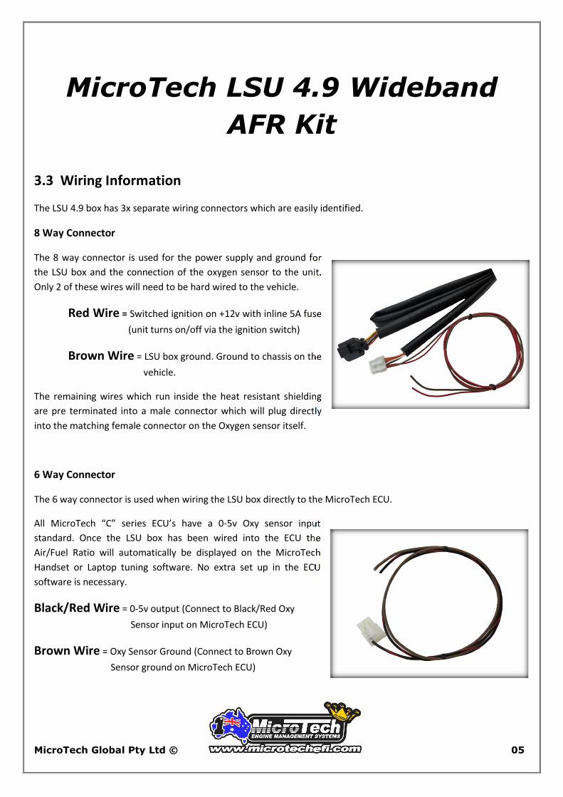
8 Way Connector
The 8 way connector is used for the power supply and ground for
the LSU box and the connection of the oxygen sensor to the unit.
Only 2 of these wires will need to be hard wired to the vehicle.
Red Wire = Switched ignition on +12v with inline 5A fuse
(unit turns on/off via the ignition switch)
Brown Wire = LSU box ground. Ground to chassis on the
vehicle.
The remaining wires which run inside the heat resistant shielding
are pre terminated into a male connector which will plug directly
into the matching female connector on the Oxygen sensor itself.
6 Way Connector
The 6 way connector is used when wiring the LSU box directly to the MicroTech ECU.
All MicroTech “C” series ECU’s have a 0-5v Oxy sensor input
standard. Once the LSU box has been wired into the ECU the
Air/Fuel Ratio will automatically be displayed on the MicroTech
Handset or Laptop tuning software. No extra set up in the ECU
software is necessary.
Black/Red Wire = 0-5v output (Connect to Black/Red Oxy
Sensor input on MicroTech ECU)
Brown Wire = Oxy Sensor Ground (Connect to Brown Oxy
Sensor ground on MicroTech ECU)
MicroTech Global Pty Ltd © 05
MicroTech LSU 4.9 Wideband
AFR Kit
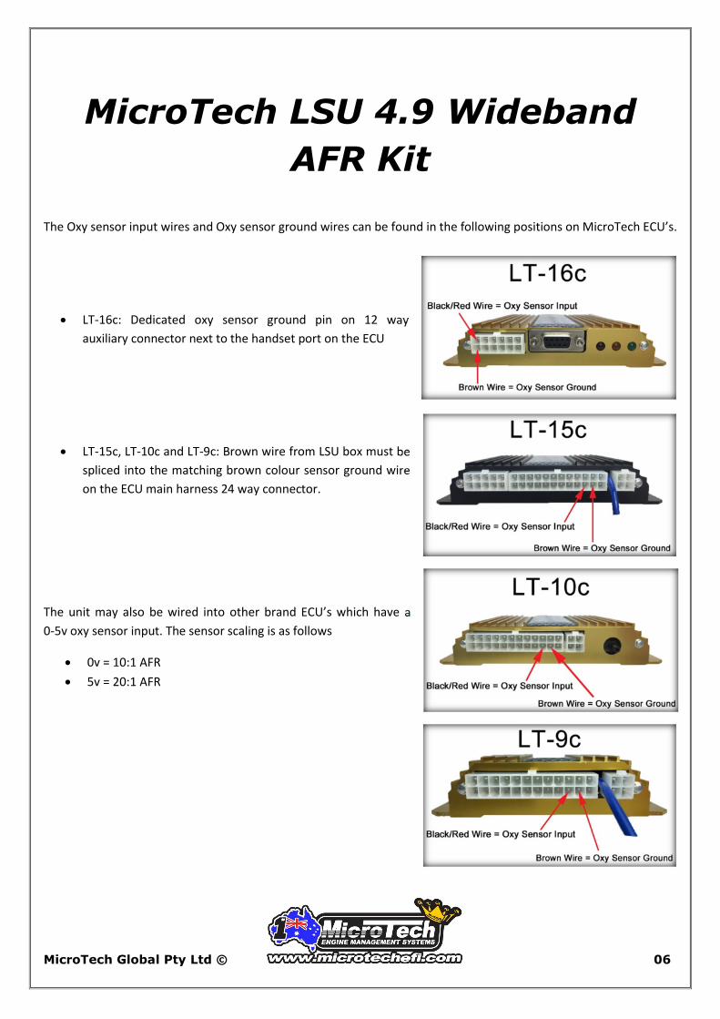
The Oxy sensor input wires and Oxy sensor ground wires can be found in the following positions on MicroTech ECU’s.
LT-16c: Dedicated oxy sensor ground pin on 12 way
auxiliary connector next to the handset port on the ECU
LT-15c, LT-10c and LT-9c: Brown wire from LSU box must be
spliced into the matching brown colour sensor ground wire
on the ECU main harness 24 way connector.
The unit may also be wired into other brand ECU’s which have a
0-5v oxy sensor input. The sensor scaling is as follows
0v = 10:1 AFR
5v = 20:1 AFR
MicroTech Global Pty Ltd © 06
MicroTech LSU 4.9 Wideband
AFR Kit
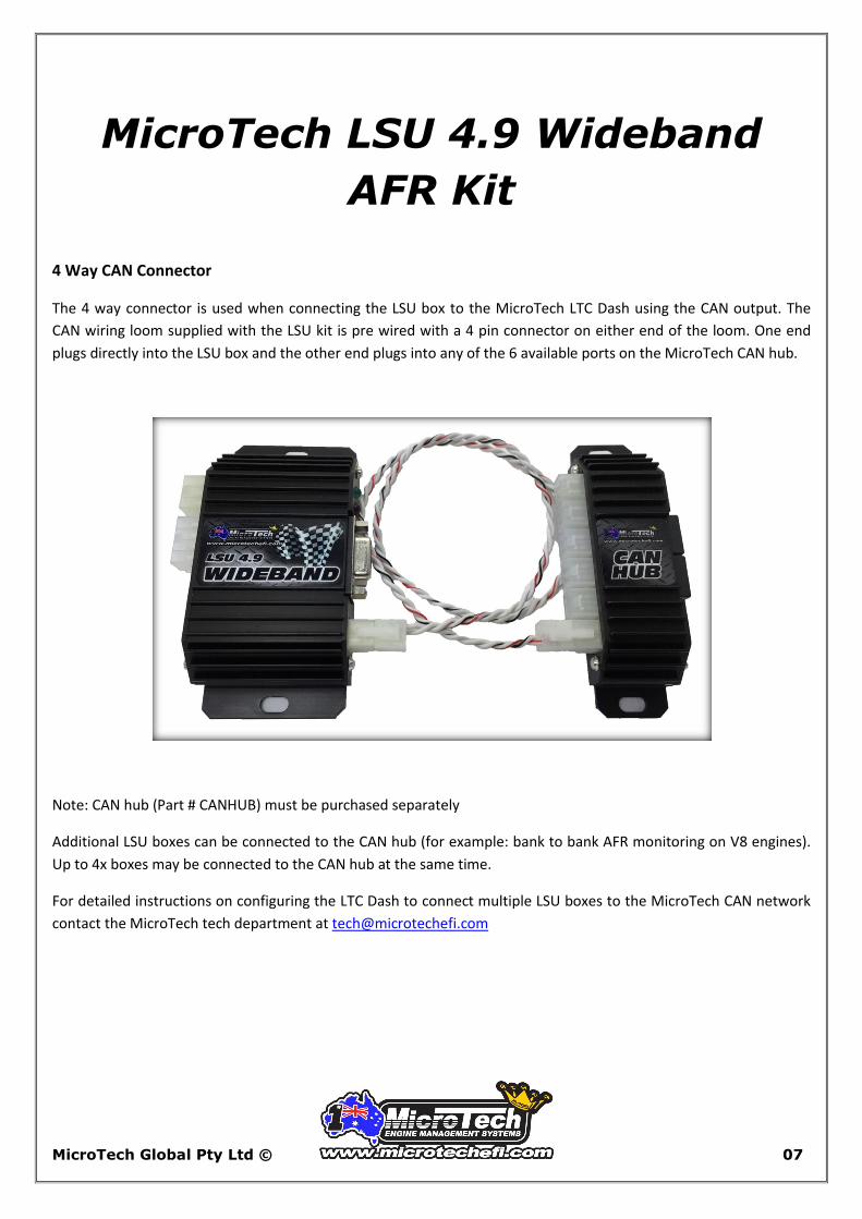
4 Way CAN Connector
The 4 way connector is used when connecting the LSU box to the MicroTech LTC Dash using the CAN output. The
CAN wiring loom supplied with the LSU kit is pre wired with a 4 pin connector on either end of the loom. One end
plugs directly into the LSU box and the other end plugs into any of the 6 available ports on the MicroTech CAN hub.
Note: CAN hub (Part # CANHUB) must be purchased separately
Additional LSU boxes can be connected to the CAN hub (for example: bank to bank AFR monitoring on V8 engines).
Up to 4x boxes may be connected to the CAN hub at the same time.
For detailed instructions on configuring the LTC Dash to connect multiple LSU boxes to the MicroTech CAN network
contact the MicroTech tech department at [email protected]
MicroTech Global Pty Ltd © 07

MicroTech LSU 4.9 Wideband
AFR Kit
3.4 LTC Dash Set up
The MicroTech LTC Dash has a dedicated screen (screen #3) for displaying Air/Fuel Ratio in a large digit format.
To activate this function from the LTC Dash Data display screen:
Select Handset mode (touch top left corner of the
screen)
Arrow down 2 clicks (using the blue arrows) to set up
screen #2
Arrow across to the right 4 clicks (using the blue arrows)
to “Data 3_1”
MicroTech Global Pty Ltd © 08
MicroTech LSU 4.9 Wideband
AFR Kit
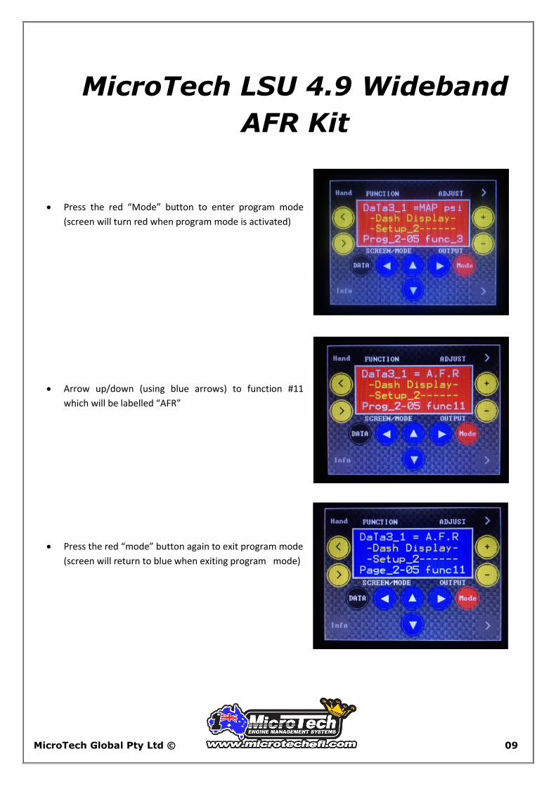
Press the red “Mode” button to enter program mode
(screen will turn red when program mode is activated)
Arrow up/down (using blue arrows) to function #11
which will be labelled “AFR”
Press the red “mode” button again to exit program mode
(screen will return to blue when exiting program mode)
MicroTech Global Pty Ltd © 09

MicroTech LSU 4.9 Wideband
AFR Kit
Touch the “Hand” icon in the top left screen (or press the
external button) to return to display mode. Screen #3
will now be set up as a large digit Air/Fuel Ratio display
screen.
For further information on programming AFR warnings and limits on the LTC Dash refer to the LTC Dash manual.
3.5 MicroTech Handset Connection
The MicroTech Handset is primarily used with the LSU box for factory
diagnostics and testing purposes. However, Air/Fuel Ratio can be viewed
on the Handset by simply connecting the handset cable directly to the 9
pin serial port on the side of the LSU 4.9 box.
Units will be displayed on the Data screen in both Air/Fuel
Ratio or Lambda.
All other functions being displayed are for factory testing and calibration, diagnostic purposes or future upgrades
and should be ignored.
MicroTech Global Pty Ltd © 10
MicroTech LSU 4.9 Wideband
AFR Kit
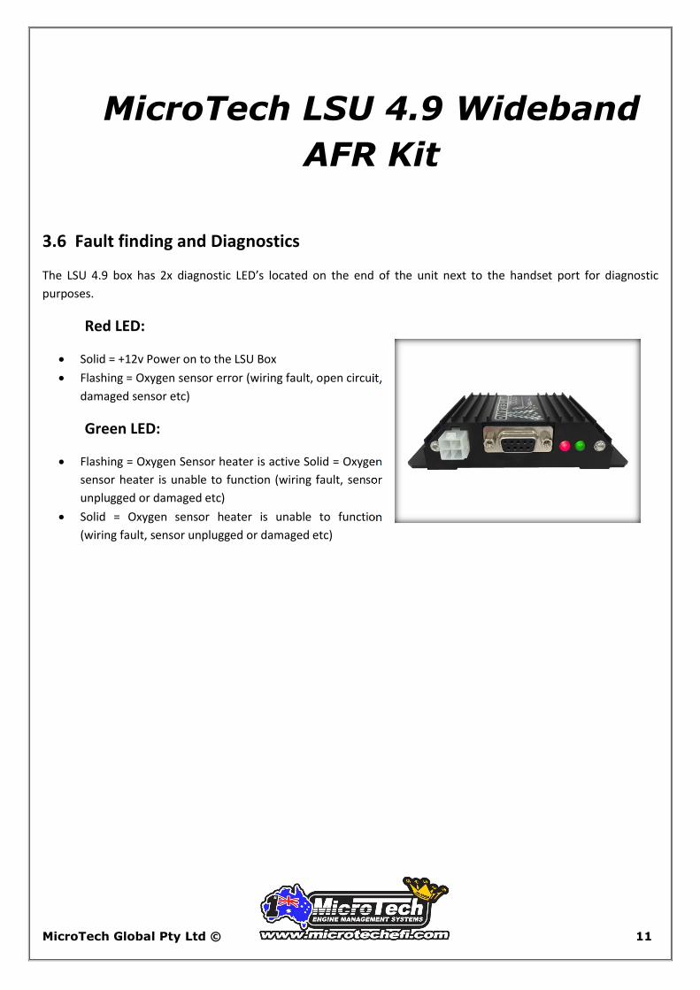
3.6 Fault finding and Diagnostics
The LSU 4.9 box has 2x diagnostic LED’s located on the end of the unit next to the handset port for diagnostic
purposes.
Red LED:
Solid = +12v Power on to the LSU Box
Flashing = Oxygen sensor error (wiring fault, open circuit,
damaged sensor etc)
Green LED:
Flashing = Oxygen Sensor heater is active Solid = Oxygen
sensor heater is unable to function (wiring fault, sensor
unplugged or damaged etc)
Solid = Oxygen sensor heater is unable to function
(wiring fault, sensor unplugged or damaged etc)
MicroTech Global Pty Ltd © 11