Embed Size (px)
Citation preview

A R C H I V E S
o f
F O U N D R Y E N G I N E E R I N G
Published quarterly as the organ of the Foundry Commission of the Polish Academy of Sciences
ISSN (1897-3310) Volume 17
Issue 1/2017
179 – 191
33/1
A R C H I V E S o f F O U N D R Y E N G I N E E R I N G V o l u m e 1 7 , I s s u e 1 / 2 0 1 7 , 1 7 9 - 1 9 1 179
Microstructure, SDAS and Mechanical
Properties of A356 alloy Castings Made in
Sand and Granulated Blast Furnace Slag
Moulds
B.R. Jinugu*, N.M. Inampudi Department of Metallurgical Engg, Andhra University, Visakhapatnam – 530003, India
*Corresponding author. E-mail address: [email protected]
Received 01.12.2016; accepted in revised form 19.01.2017
Abstract
Investigations were carried out to ensure the granulated blast furnace (GBF) slag as an alternative mould material in foundry industry by
assessing the cast products structure property correlations. Sodium silicate-CO2 process was adopted for preparing the moulds. Three
types of moulds were made with slag, silica sand individually and combination of these two with 10% sodium silicate and 20 seconds CO2
gassing time. A356 alloy castings were performed on these newly developed slag moulds. The cast products were investigated for its
metallography and mechanical properties. Results reveal that cast products with good surface finish and without any defects were
produced. Faster heat transfers in slag moulds enabled the cast products with fine and refined grain structured; and also lower Secondary
Dendrite Arm Spacing (SDAS) values were observed than sand mould. Slag mould casting shows improved mechanical properties like
hardness, compression, tensile and impact strength compared to sand mould castings. Two types of tensile fracture modes, namely
cleavage pattern with flat surfaces representing Al−Si eutectic zone and the areas of broken Fe-rich intermetallic compounds which appear
as flower-like morphology was observed in sand mould castings. In contrast, GBF slag mould castings exhibit majority in dimple fracture
morphology with traces of cleavage fracture. Charpy impact fractured surfaces of sand mould castings shows both transgranular and
intergranular fracture modes. Only intergranular fracture mode was noticed in both GBF slag and mixed mould castings.
Keywords: Silica sand; GBF slag; CO2 process; A 356 alloy castings; SEM-EDX; Mechanical properties
1. Introduction
Silica sand is traditionally used in the foundry applications as
a moulding material. Due to the depletion of natural materials,
there is a need to find suitable alternative material, which will
replace the conventional materials. The large scale
industrialization has resulted accumulation of huge amount of
industrial wastes, endangering the environment in terms of land,
air and water pollution. In order to use the industrial waste in
huge quantities efforts are being made to use the same as a
substitute of natural resources. Various efforts have been made to
use industrial solid wastes like fly ash, red mud, blast furnace slag
etc. in civil and construction works. In view of the large quantity
of granulated blast furnace (GBF) slag availability, having similar
physical and chemical properties with silica sand and limited
literature on GBF slag usage in foundry industry attempts are
made to address the same. Present investigations were carried out
to ensure the granulated blast furnace (GBF) slag as an alternative

180 A R C H I V E S o f F O U N D R Y E N G I N E E R I N G V o l u m e 1 7 , I s s u e 1 / 2 0 1 7 , 1 7 9 - 1 9 1
mould material in foundry industry by assessing the cast products
structure property correlations. Hence, investigation were
performed on A356 (Al-7.5% Si) alloy castings in sand, GBF slag
and combinations of these two moulds; and same castings were
characterized for its microstructure and mechanical properties.
Owing to the superiority, sodium silicate - CO2 process was
adopted for all the moulds preparation [1, 2]. The obtained results
may be useful for ensuring GBF slag as an alternative mould
material in non ferrous foundries.
2. Materials and methods
In the present investigation two types of materials namely
high silica sand and granulated blast furnace (GBF) slag was
chosen. Silica sand is the principle moulding sand used in foundry
industries. It was procured from Chirala, Andhra Pradesh, India.
Blast furnace slag in granulated form procured from
Visakhapatnam Steel Plant, Visakhapatnam, India. Preheating of
the silica sand and granulated blast furnace slag (GBF)
particulates were carried out in a muffle furnace at 3000 C for 3
hours to get rid of the any moisture presence in them.
Investigations on their chemical, physical and moulding
properties were reported in earlier works [3].
2.1. Melting and casting practice
Al-Si alloy having a wide range of applications in the
automotive and aerospace, also provides the most significant part
of all shaped castings manufactured. Hence, melting and casting
practice of A 356 (Al-7.5%Si) alloy castings was performed on
these newly made GBF slag moulds. For this study three types of
moulds were selected, namely; Type 1: 100% Silica sand; Type 2:
100% GBF slag; and Type 3: mixture of 50% GBF slag + 50%
Sand. The optimum mould properties were obtained by addition
of 10% sodium silicate along with a CO2 gassing of 15-20
seconds duration [4]. This work is first of its kind; hence, only
regular shaped cylindrical castings (18 X 180 mm diameter and
length respectively) are aimed to cast. Cope and drag as well as
split pattern was used for preparing the mould with mould cavity.
A356 alloy ingots of 500 grams in weight was taken in a graphite
crucible and melted separately in a calibrated high temperature
melting furnace at 750 OC. The molten metal was allowed to fill
in the mould cavities via sprue, runner and in gates; care was
taken to ensure continuous and smooth flow of the liquid metal
while filling in the mould cavities. Riser was placed in the mould
to ensure complete mould cavity filling. After cooling the
castings were withdrawn from mould boxes and same was
undergone for further metallographic and mechanical properties
evaluation. Figure 1 shows the finished A356 alloy cylindrical
castings before and after machining.
Fig. 1. A 356 alloy finished cylindrical castings before and after
machining
2.2. Metallographic evaluation - SEM-EDS
analysis
Scanning Electron Microscope with Energy Dispersive
spectrum analysis was carried out to assess the morphological
changes and the elemental analysis on castings made through
sand, slag and mixed moulds. The analysis was carried out using
Scanning Electron Microscope (SEM) fitted with ED’s spectrum
(Model: JEOL-JSM-6480 LV). Secondary Dendrite Arm Spacing
(SDAS) measurements were carried out on all the samples. Image
J software was used to evaluate the same.
2.3. Mechanical properties evaluation
2.3.1. Hardness studies
Rockwell hardness tests were carried out on these cast
samples to have comparative strength properties of the slag and
sand castings. Standard testing procedure was followed by
applying the minor load of 10 kgf; and major load of 100 kgf with
HRB scale. The hardness survey was done across the longitudinal
and transverse directions of the samples. Also hardness was
measured at four different diagonals of the specimen and
averaged. An average of eight readings was considered to report
the respective hardness value.
2.3.2. Tensile testing
Tensile specimens were casted directly from respective slag,
sand and combination of sand and slag moulds. Melting and
casting procedure to make these tensile specimens was followed
the same procedure as discussed in section 2.1. Figure 2 show the
standard tensile test specimen and its experimental set up
respectively. Tensile strength of materials under investigation
was determined by using calibrated computer controlled servo
hydraulic universal testing machine (model: Fuel Instruments and
Engineers (FIE –UTE 100 with 1000 tons capacity). The test was
conducted at a constant cross head speed of 0.5 mm/min. The
testing procedure was followed as per ASTM E-8 standards.
Online plotting of load versus extension has done continuously
though a data acquisition system. Figure 3 shows the A356 alloy
tensile specimens before and after testing of sand, slag and
mixture of these two castings respectively.

A R C H I V E S o f F O U N D R Y E N G I N E E R I N G V o l u m e 1 7 , I s s u e 1 / 2 0 1 7 , 1 7 9 - 1 9 1 181
Fig. 2. (a) Standard tensile specimen (b) Closer view of the tensile testing
Fig. 3. Tensile specimens: (a) before testing (b) after testing
2.3.3. Compression testing Standard cylindrical specimens with aspect ratio (H/D=1.0) of
16 mm length and 16 mm diameter were machined from the
cylindrical finger castings of respective materials. Sample edges
were chamfered to minimize the folding. Concentric grooves of
0.5 mm depth were made on both the end surfaces of the sample.
These samples were compressed by placing between the flat
platens at a constant cross head speed of 0.5 mm/min in dry
condition, using a calibrated computer controlled servo hydraulic
1000T universal testing machine (Model: FIE-UTE). Cold work
die steel dies (flat flattens) were machined to produce smooth
finish to yield low friction. Figure 4 shows the cylindrical samples
of A356 alloy before and after deformation respectively. Online
plotting of load versus displacement has done continuously
through a data acquisition system.
Fig. 4. Cylindrical samples with aspect ratio = 1.0 showing bulge profiles before and after deformation under compression
2.3.4. Charpy Impact testing
Charpy impact tests were carried out on these cast samples to
have comparative impact properties of the slag and sand castings.
The V-notched impact test standard specimens with dimensions of
10 X 10 X 55 mm were made according to ASTM-A370. The test
was conducted at room temperature and was repeated for three
times of each material. An average of three readings was
considered to report the respective impact value. The Charpy
impact test machine (Model: R17 DT 63M4: Micro technology,
Chennai, India) with calibrated was chosen for above test. Figure
5 shows the A356 alloy Charpy impact specimens before after
testing.
Fig. 5. Charpy impact specimens: (a) before testing (b) after testing

182 A R C H I V E S o f F O U N D R Y E N G I N E E R I N G V o l u m e 1 7 , I s s u e 1 / 2 0 1 7 , 1 7 9 - 1 9 1
3. Results and discussion
3.1. A356 alloy laboratory castings – mould
heat transfer rates
The cylindrical finger castings after cooling were examined
and revealed that very less amount of mould ingredients were
stick to the casting surfaces; further slag castings shows cleaned
surface finish on par with sand castings. All the castings show
good surface finish with no surface defects; it also reveals good
dimensional accuracy. Before and after machined cylindrical
castings shows no porosity or other surface defects presence in
any of the either sand or slag mould castings.
Mould heat transfer rate plays a significant role in obtaining
final microstructure and its corresponding mechanical properties
of the castings [5-12]. Studies were performed to evaluate the
mould heat transfer rates of slag, sand and mixture of these two
moulds. The same was measured by observing the mould
temperature at three locations namely near the runner, riser and
mid-way of the mould cavity with solidification times. This
assessment was done separately for all the three types of moulds;
the obtained results were shown in figure 6 (a-c). These figures
reveal that initial solidification period (up to 30 minutes duration)
increase in mould temperature was noticed then slowly lowering
the mould temperature; the same trend was observed for all the
three moulds. At any given freezing time GBF slag mould shows
more mould temperature, then mixture of sand-slag mould and
finally sand moulds. This was true for all the three locations
namely runner, riser and mould mid way. From these results it
can conclude that GBF slag moulds facilitate faster heat transfer
rates than sand moulds; hence faster solidification rates of the
castings.
(a) (b)
(c)
Fig. 6. Variation in mould temperatures at various locations during freezing of A356 alloy castings for Sand, GBF slag and mixture of
these two moulds: (a) near the Runner (b) near the Riser, and (c) Midway of the mould
3.2 Microstructure evaluation
Figure 7(a-c) indicate the SEM micrographs of A356 alloy
castings made in sand, GBF slag and mixture of these two moulds
respectively. A356 aluminium alloy is a hypo eutectic alloy (Al-
7.5%Si); microstructure mainly consists of soft & ductile α -
aluminum dendrite phase containing magnesium and silicon in
solution and hard & brittle eutectic phase (α-Al+Si) in the inter-
dendrite region, as shown in figures 7(a-c). The fine and refined
grain structure was obtained for GBF slag mould samples than
sand mould, figure7 (b); this might be due to the faster
solidification rates in these slag moulds. Microstructure of mixed
mould casting shows in between the sand and slag castings. In
general, the rate at which a casting cools affects its
microstructure, quality and properties. The sand mould casting
process cool slowly compare to either metallic or chromite sand
moulds. This slow cooling increases the metal’s grain size,
creating a coarse microstructure; coarse grain structure weakens
A R C H I V E S o f F O U N D R Y E N G I N E E R I N G V o l u m e 1 7 , I s s u e 1 / 2 0 1 7 , 1 7 9 - 1 9 1 183
the casting [13-16]. The same phenomenon was noticed in the
present investigation. Conversely, the slag mould process are able
to cool more quickly, resulting microstructure with small size
grains.
(a) (b)
(c)
Fig. 7. SEM micrographs of A356 alloy castings: (a) Silica sand mould (b) GBF Slag mould and (c) Mixture of 50% GBF slag and 50%
Silica sand mould.
As cast microstructures were analyzed for its Secondary
Dendrite Arm Spacing (SDAS) values by using Simagis
microstructure image software. The linear line intercept method
was used to measure the dendrite arm spacing with different
orientations at different locations [17, 18]. Each micrograph was
divided into three locations, namely location 1, 2 and 3. A line
along the dendrite arm is drawn and the number of arms crossing
this line was then counted. Figure 8 (a-c) shows the typical A356
alloy microstructures with line drawn for measurement of SDAS
of silica sand, GBF Slag and mixture of these two moulds
respectively. The results from SDAS measurements were shown
in table 1; average SDAS values of silica sand, GBF Slag and
mixture of these two moulds were 42μm, 31μm and 38μm
respectively. GBF slag mould castings show lower SDAS values
due to the fast mould cooling rates than either silica sand or mixed
mould.

184 A R C H I V E S o f F O U N D R Y E N G I N E E R I N G V o l u m e 1 7 , I s s u e 1 / 2 0 1 7 , 1 7 9 - 1 9 1
(a) (b)
(c)
Fig. 8. SEM micrographs for secondary dendrite arm spacing (SDAS) measurements at different locations of A356 alloy castings: (a) silica
sand mould (b) GBF slag mould and (c) Mixture of 50% GBF slag and 50% silica sand mould.
Table 1.
Measured values of Secondary Dendrite Arm Spacing (SDAS)
S. No. Cast Sample Location
Secondary dendrite arm spacing, (SDAS), μm
Orientations Average SDAS
1 2 3 4 5 6 7
1. 100% Sand
mould
1 45 39 40 41 42 40 47 42
42 2. 2 42 40 41 43 44 42 43 43
3. 3 42 43 41 40 43 42 42 41
4. 100% GBF Slag
mould
1 25 32 32 30 31 31 31 30
31 5. 2 33 34 31 31 33 33 32 32
6. 3 35 34 31 34 33 34 30 33
7. 50%GBF Slag +
50% Sand
mould
1 34 37 37 36 37 41 36 36
38 8. 2 38 40 37 37 35 32 33 41
9. 3 37 40 39 37 40 39 39 38
A R C H I V E S o f F O U N D R Y E N G I N E E R I N G V o l u m e 1 7 , I s s u e 1 / 2 0 1 7 , 1 7 9 - 1 9 1 185
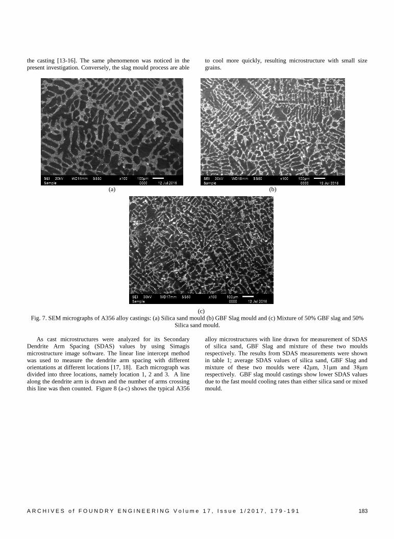
3.3. Hardness survey
Figure 9(a-c) shows the hardness profiles of A356 alloy
castings made by sand, GBF slag and mixture of slag and sand
moulds respectively. The obtained hardness (HRB scale) values
were similar to the available literature [19]. Consistent and
uniform hardness was observed throughout the cross section of
the sample; this was true for all the castings under investigation.
However sand casting shows lower hardness compared to slag
castings. Enhanced hardness in slag castings might be due to the
presence of fine grained microstructure consists of α -Al dendrites
and hard & brittle eutectic phase (α –Al+Si). In case of mixed
mould castings hardness was in between the slag and sand mould
castings.
(a) (b) (c)
Fig. 9. Hardness (HRB) profile of A356 aluminium alloy castings along the cross section of the sample: (a) 100% Silica Sand (b) 100%
GBF Slag and (c) Mixture of 50% GBF slag and 50% Silica sand
3.4. Compression and tensile properties
Compression and tensile properties of A356 alloy made
through sand, slag and mixture of these two moulds was studied.
The obtained results were shown in figure 10 and 11 for
compression and tensile properties respectively. The load
requirement increased with increase in deformation for the
material under investigation. The slag mould castings show higher
loads with slightly improved amount of deformation than the sand
moulds. This might be due to slag moulds enable to have faster
cooling rates and lead to a fine grain structure than castings made
in sand moulds. Whereas mixed mould castings exhibit the
properties in between sand and slag mould castings. Grain size
has a significant effect on strength of the metals. As the grain size
decreases the strength and ductility of metal increase, micro
porosity in the casting decreases and the tendency for the casting
to crack during solidification decreases. The strength of the
materials is expected to increase by the presence of fine grain
structure due to the strengthening effects occurred in combination
of both grain boundary and strain hardening mechanisms [20].
Fig. 10. Compression properties of A356 alloy made in sand, GBF
slag and mixture of these two moulds (aspect ratio (H/D) =1.0)
Fig. 11. Tensile properties of A356 alloy made in sand, GBF slag
and mixture of these two moulds
Further SEM studies on tensile fractured specimens were
evaluated and same shown in figure 12 (a-c) for sand, slag and
combinations of these two moulds castings respectively. A 356
alloy casted in 100% sand mould shows two types of fracture
characteristics, as shown in figure 12 (a). The areas labeled as ‘C’
show a cleavage pattern with flat surfaces representing Al−Si

186 A R C H I V E S o f F O U N D R Y E N G I N E E R I N G V o l u m e 1 7 , I s s u e 1 / 2 0 1 7 , 1 7 9 - 1 9 1
eutectic zone. In these flat areas, the Si platelet might be torn off
from the Al matrix, leaving a terrace with a smooth surface. These
faces were more probably formed as a result of fracture of brittle
Si phase crystals [21]. In the present investigation of sand mould
castings, larger Secondary Dendrite Arm Spacing (SDAS) and
elongated eutectic silicon particles were observed. Generally
elongated eutectic silicon particles fracture more frequently than
the spherical silicon particles since they are the main sources of
stress concentration [22]. The micrograph (figure 12 (a)) also
shows the areas of broken Fe-rich intermetallic compounds,
labeled as ‘B’. These areas appear as flower-like morphology with
no evident cleavage faces. The existence of these areas might be
due to severe breakup occurred at these intermetallic areas [23].
In general intermetallics have poor deformation properties; during
crack propagation the stress field of the main crack broke the
intermetallics only without destroying the boundaries among the
intermetallic particles or the boundaries between the intermetallic
phases and the Al−Si eutectic [24].
In contrast, SEM micrographs of A356 alloy tensile fractured
samples obtained by 100% GBF slag mould exhibit majority in
dimple fracture morphology with traces of cleavage fracture.
These dimples were deep and distributed uniformly, as shown in
figure 12(b). The smaller SDAS and finer eutectic silicon
particles in this casted sample make the grain cell boundaries
more discontinuous. Therefore, a stronger interaction between slip
bands and plastic flow generates in the grain boundaries [25, 26].
The cracking of eutectic silicon particles takes place in the grain
boundaries, and the final fracture path tends to pass through the
eutectic phase along the grain boundaries of the α-Al primary
phase. As a result, the fracture generates mostly by dimple rupture
with cracked eutectic silicon particles, and exhibits an
intergranular fracture mode, lead to the optimum mechanical
properties [27]. In case of mixed mould cast product fracture
behavior reveal the mixed quasi-cleavage type morphology. Here
the dimples were flat and distributed non-uniformly, as shown in
figure 12 (c). Figure 13 (a-c) shows the EDS of tensile fracture
surfaces of A356 alloy made by various moulds of sand, GBF slag
and mixture of sand and slag. It was clearly evident that presence
of Fe-rich intermetallics in the alloy morphology.
(a) (b)
(c)
Fig. 12. SEM micrographs for tensile fractured surfaces of A356 alloy castings by various moulds: (a) 100% Sand (b) 100% GBF slag and
(c) combinations of these two moulds.

A R C H I V E S o f F O U N D R Y E N G I N E E R I N G V o l u m e 1 7 , I s s u e 1 / 2 0 1 7 , 1 7 9 - 1 9 1 187
(a)
(b)
(c)
Fig. 13. EDS of tensile fracture surfaces of A356 alloy made by various moulds: (a) 100 % Sand (b) 100% GBF Slag (c) Mixture of Sand
and Slag
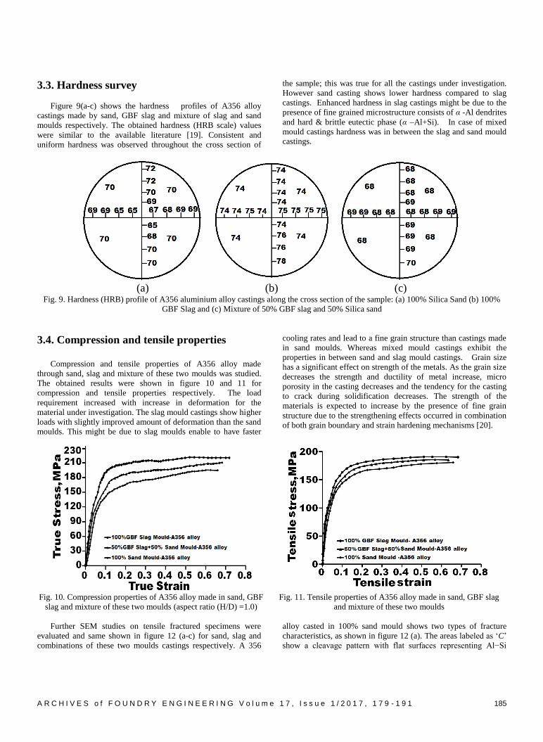
3.5. Charpy impact properties
In case of impact strength, GBF slag castings shows similar
results with silica sand castings. The summary of the obtained
A356 alloy mechanical properties for all the moulds under
investigation was shown in table 2. SEM studies on charpy
impact fractured specimens were evaluated and same shown in
figure 14 (a-c) for sand, slag and combinations of these two
moulds castings respectively. The 100% sand mould castings
shows both transgranular and intergranular fracture modes,
however majority of the areas shows transgranular fracture mode,
as shown in figure 14(a). The fracture profile follows a
preferential path through the eutectic phase, and in many cases it
also follows through a secondary dendrite arm. In general fracture
development involves the cracking of Si particles. Once the
particle cracks, a micro void is formed and tends to grow. This
particle cracking process continues until a critical volume fraction
of cracked particles is reached. Eventually, the alloy fails because
of a rapid linking process among micro cracks. This linking
process depends on the size of the Secondary Dendrite Arm
Spacing (SDAS). When SDAS is large, this linkage is
transgranular, whereas in small SDAS it becomes intergranular
188 A R C H I V E S o f F O U N D R Y E N G I N E E R I N G V o l u m e 1 7 , I s s u e 1 / 2 0 1 7 , 1 7 9 - 1 9 1
[28-31]. In this present investigation larger SDAS values were
observed for sand mould castings; hence majority of the
transgranular fracture was noticed. However, smaller SDAS were
reported in GBF slag and mixed mould castings, hence only
intergranular fracture mode was noticed on these samples, as
shown in figure 14 (b & c). Figure 15 (a-c) shows EDS of
intermetallic compounds on the impact fracture surface of A356
alloy made by various moulds of sand GBF slag and combinations
of these two moulds respectively.
Table 2.
Mechanical properties of A356 alloy made through sand, slag and combination of these two moulds after compression, tensile and impact
testing
S.
No. Material Mould material Hardness
Tensile properties Compression properties Impact
strength
(joules) Y.S
(MPa)
UTS
(MPa)
break
stress
(MPa)
%
Elongatio
n
UTS
(MPa)
break stress
(MPa)
1. A356
alloy
100% Sand 62 HRB 178 183 183 1.21 195 194 6.0
100% GBF Slag 75HRB 187 190 188 1.21 220 215 6.2
50% GBF Slag
+ 50%Sand 68 HRB 182 185 183 1.20 210 196 6.0
(a) (b)
(c)
Fig. 14. SEM micrographs of Impact fractured specimen of A356 alloy castings made by various moulds: (a) 100% Sand (b) 100% GBF
slag and (c) combinations of these two moulds

A R C H I V E S o f F O U N D R Y E N G I N E E R I N G V o l u m e 1 7 , I s s u e 1 / 2 0 1 7 , 1 7 9 - 1 9 1 189
a)
b)
c)
Fig. 15. EDS of the impact fracture surface of A356 alloy made by various moulds: (a) 100% Sand (b) 100% GBF Slag (c) combinations
of these two moulds
4. Conclusions
1. In slag moulds, while casting no burning, neither dripping
nor collapse of the mould walls was observed. Also, cast
products with good surface finish, no surface defects and
without porosity were produced.
2. Faster heat transfer in slag moulds enabled the cast products
with fine and refined grain structured than sand mould;
hence, lower Secondary Dendrite Arm Spacing (SDAS)
values were reported in slag mould castings than sand.
3. Consistent and uniform hardness was observed throughout
the cross section of the samples. However sand mould
casting shows lower hardness compared to slag castings.
The slag mould castings show higher compression and
tensile strengths with slightly improved amount of
deformation than the sand moulds.
4. Sand mould castings shows two types of fracture
characteristics, namely cleavage pattern with flat surfaces
representing Al−Si eutectic zone and the areas of broken Fe-
rich intermetallic compounds with appear as flower-like
190 A R C H I V E S o f F O U N D R Y E N G I N E E R I N G V o l u m e 1 7 , I s s u e 1 / 2 0 1 7 , 1 7 9 - 1 9 1
morphology. In contrast, GBF slag mould castings exhibit
majority in dimple fracture morphology with traces of
cleavage fracture.
5. Charpy impact fractured surfaces of sand mould castings
shows both transgranular and intergranular fracture modes.
Only intergranular fracture mode was noticed in both GBF
slag and mixed mould castings.
6. Based on these present investigations, GBF Slag can be
used as alternative mould materials; and these moulds lead
to produce castings with improved surface finish, enhanced
metallurgical and mechanical properties while reduced
operational costs.
Acknowledgements
Authors thank the DST –Fly Ash unit, New Delhi, India for
their financial support (Grant Ref No: FAU/DST/600(52)/2012-
13). Special thanks to M/s. Visakhapatnam Steel Plant,
Visakhapatnam, India for supply of GBF Slag this study.
References
[1] Fan Zitian, Huang Naiyu & Dong Xuanpu, (2004). In house
reuse and reclamation of used foundry sands with sodium
silicate binder. International Journal of Cast Metals
Research. 17, 51-56.
[2] Ahmed, S. & Ramrattan, S.N. (1990). Comparison of
Handling Properties Using CO2 Activated Binder Systems,
AFS Transactions. 98, 577-586.
[3] Narasimha Murthy, I. & Babu Rao J. (2015). Investigations
on Physical and Chemical Properties of High Silica Sand,
Fe-Cr Slag and Blast Furnace Slag for Foundry Applications.
Resource Efficient Waste Management. Nov 2015, 553-561.
[4] Narismha Murthy, I., Arun Babu, N., Babu Rao J. (2015).
High carbon Ferro Chrome Slag and GBF Slag – Alternative
Mould Material for Foundry Industry – 5th International
Conference on Solid Waste Management, (5th IconSWM
2015), Bangalore, India, 24 – 27 November, 2015, p. 62.
[5] Adedayo, A.V. & Aremo B. (2011). Influence of Mould Heat
Storage Capacity on Properties of Grey Iron. Journal of
Minerals & Materials Characterization & Engineering.
10(4), 387-396.
[6] HU Xiaowu, AI Fanrong, & YAN Hong, (2012). Influences
of pouring temperature and cooling rate on microstructure
and mechanical properties of casting Al-Si-Cu aluminum
alloy, Acta Metall. Sin.(Engl. Lett.). 25(4), 272-278.
[7] Wasiu Ajibola Ayoola, Samson Olurropo Adeosun, Olujide
Samuel Sanni, & Akinlabi Oyetuni (2012). Effect of Casting
Mould on Mechanical Properties of 6063 Aluminium alloy,
Journal of Engineering Science and Technology. 7(1), 89-96.
[8] Ying-Dong Qu, Mei-Ling Jin, Gang Qin, Rong-De Li, Min-
Qiang Gao, Feng-Shuang Sun, & Jun-Hua You (2014).
Ultra-Long Pore Fabrication Process by Pulling–Casting in
Aluminum Alloy. Materials and Manufacturing Processes.
29(10), 1205-1209.
[9] Minghui Ding, Jingtao Song, & Liu Honghui, (2014). Effect
of Pouring Temperature on Typical Structure of Thin-Walled
ZL105A Alloy Casting. Materials and Manufacturing
Processes. 29(7), 853-863.
[10] Ahmad, H., Naher, S. & Brabazon, D. (2014). The Effect of
Direct Thermal Method, Temperature and Time on
Microstructure of a Cast Aluminum Alloy. Materials and
Manufacturing Processes. 29(2), 134-139.
[11] Rao A. Shailesh, S Mahantesh. Tattimani, S Shrikantha Rao
(2015). Understanding Melt Flow Behavior for Al-Si Alloys
Processed Through Vertical Centrifugal Casting. Materials
and Manufacturing Processes. 30(11), 1305-1311.
[12] Hsien-Chi Sun, & Long-Sun Chao, (2009), An Investigation
into the Effective Heat Transfer Coefficient in the Casting of
Aluminum in a Green-Sand Mold, Materials Transactions.
The Japan Institute of Metals. 50(6), 1396-1403.
[13] Mondolfo, L.F. (1943). Metallography of Aluminum Alloys,
New York John Wiley & sons, Inc.
[14] Ye Haizhi (2003). An Overview of the Development of Al-
Si-Alloy Based Material for Engine Applications. Journal of
Materials Engineering and Performance, ASM International.
12(3), 288-297.
[15] Mae, H., Teng, X., Bai, Y. & Wierzbicki, (2008).
Comparison of ductile fracture properties of aluminium
castings: sand mold vs. metal mold. Int. Journal of Solids
and Structures. 45, 1430-1444.
[16] Casting. ASM Hand book (1992). vol 15, ASM
International.
[17] D. Hanumantha Rao., G.R.N Tagore., G Ranga Janardhana
(2010). Evolution of Artificial Neural Network (ANN)
model for predicting secondary dendrite arm spacing in
aluminium alloy casting. J. Braz. Soc. Mech. Sci. & Eng.
32(3), 276-281.
[18] Kadushnikov, M., Alievskiĭ, V.M., Somina, S.V.,
Kozerchuk, A.L. & Petrov, M.S. (2011). Digital microscopy
from Nano to macro, using the SIAMS image-analysis
system. Journal of Optical Technology. 78(1), 61-65.
[19] Yildirim, M. & Özyürek, D. (2014). The effects of mould
materials on microstructure and mechanical properties of
cast A356 alloy. Journal of Advanced Materials and
Processing. 2(4), 3-12.
[20] M.N. Shetty, (2013). Dislocations and Mechanical behavior
of Materials, Delhi, India, PHI Learning, Pvt. Ltd.
[21] Weng-ming JIANG, Zi-tian FAN, & De-jun LIU (2012),
Microstructure, tensile properties and fractography of A356
alloy under as-cast and T6 obtained with expendable pattern
shell casting process. Transaction of nonferrous metals
society of china. 22, 7-13.
[22] Wenming Jiang, Zitian Fan, Dejun Liu, Defeng Liao,
Xuanpu Dong, & Xiaoming Zong, (2013). Correlation of
microstructure with mechanical properties and fracture
behavior of A356-T6 aluminum alloy fabricated by
expendable pattern shell casting with vacuum and low-
pressure, gravity casting and lost foam casting. Materials
Science and Engineering: A. 560, 396-403.
[23] Ji-hua Peng, Xiao-long Tang, Jian-ting HE, & De-ying XU
(2011), Effect of heat treatment on microstructure and
Tensile properties of A356 alloys. Transaction of nonferrous
metals society of china. 21, 1950-1956.

A R C H I V E S o f F O U N D R Y E N G I N E E R I N G V o l u m e 1 7 , I s s u e 1 / 2 0 1 7 , 1 7 9 - 1 9 1 191
[24] Wang, Q.G. (2003). Microstructural Effects on the Tensile
and Fracture Behavior of Aluminum Casting Alloys
A356/357. Metallurgical and Materials Transactions A. 34
A, 2887-2899.
[25] Guo-hua Zhang, Jian-xin Zhang, LI Bing-chao, & Wei Cai
(2011). Characterization of tensile fracture in heavily alloyed
Al-Si piston alloy. Progress in natural science: Materials
International. 21, 380-385.
[26] Merlin M., & Garagnani, G.L. (2009). Mechanical and
microstructural characterization of A356 castings realized
with full and empty cores. Metallurgical Science and
Technology. 127(1), 21-30.
[27] Ceschini, L., Jarfors, A., Al Morri, Al., Morri, An,, Rotundo,
F., Seifeddine, S. & Toschi, S. (2014). High temperature
tensile behaviour of the A354 aluminum alloy. Materials
Science Forum. 794-796, 443-448.
[28] Casari, D., Merlin, M. & Garagnani, G.L. (2013). A
comparative study on the effects of three commercial Ti–B-
based grain refiners on the impact properties of A356 cast
aluminium alloy. Journal of Mater Science. 48, 4365-4377.
[29] Merlin, M., Timelli, G., Bonollo, F. & Garagnani, G.L.
(2009). Impact behaviour of A356 alloy for low-pressure die
casting automotive wheels. Journal of Materials Processing
Technology. 209(2), 1060-1073.
[30] Alexopoulos, D.N. (2010). Impact properties of the aircraft
cast aluminium alloy Al-7Si-0.6Mg (A357). EPJ Web of
Conferences. 02002(6), 1-8.
[31] M Amne Elahi, S.G. Shabestari, (2016). Effect of various
melt and heat treatment conditions on impact toughness of
A356 aluminum alloy. Trans. Nonferrous Met. Soc. China.
26, 956-965.