Embed Size (px)
Citation preview

Full Terms & Conditions of access and use can be found athttp://www.tandfonline.com/action/journalInformation?journalCode=yimr20
International Materials Reviews
ISSN: 0950-6608 (Print) 1743-2804 (Online) Journal homepage: http://www.tandfonline.com/loi/yimr20
Microstructural features, mechanical propertiesand high temperature failures of ferritic to ferriticdissimilar welds
Peter Mayr, Christian Schlacher, John A. Siefert & Jonathan D. Parker
To cite this article: Peter Mayr, Christian Schlacher, John A. Siefert & Jonathan D. Parker (2018):Microstructural features, mechanical properties and high temperature failures of ferritic to ferriticdissimilar welds, International Materials Reviews, DOI: 10.1080/09506608.2017.1410943
To link to this article: https://doi.org/10.1080/09506608.2017.1410943
© 2018 Institute of Materials, Minerals andMining and ASM International Published byTaylor & Francis on behalf of the Instituteand ASM International
Published online: 16 Jan 2018.
Submit your article to this journal
Article views: 188
View related articles
View Crossmark data

Microstructural features, mechanical properties and high temperature failuresof ferritic to ferritic dissimilar weldsPeter Mayr a, Christian Schlachera, John A. Siefertb and Jonathan D. Parkerb
aChair of Welding Engineering, Chemnitz University of Technology, Chemnitz, Germany; bElectric Power Research Institute, Charlotte,NC, USA
ABSTRACTDissimilar metal welds (DMWs) between ferritic steel grades are found extensively in theconstruction of thermal power plants. The potential combinations and approaches for joiningdissimilar ferritic steels are nearly limitless. For DMWs, the difference in alloy composition(specifically chromium and carbide-forming elements) provides the main driving force forcarbon diffusion during welding, post-weld heat treatment and long-term service at elevatedtemperatures. Since the high temperature creep strength of local, carbon-denuded zones canbe dramatically reduced from that of the parent or filler material, the service performance offerritic DMWs can be severely reduced. This article reviews experimental observations onmicrostructural evolution in dissimilar ferritic welds, activities to describe the observedphenomena by modelling and simulation and discusses the performance of these welds athigh temperature. Lastly, a well-engineered approach to the design of ferritic DMWs isdiscussed in the context of thermal power plants which are subject to damage by creep.
Abbreviations: HAZ: heat affected zone; PWHT: post weld heat treatment; GMAW: gas-metalarc welding; SMAW: shielded-metal arc welding; GTAW: gas tungsten arc welding; SAW:submerged arc welding; DMW: ferritic dissimilar metal weld; CGHAZ: coarse-grained heataffected zone; FGHAZ: fine-grained heat affected zone; CDZ: carbon-denuded zone; CEZ:carbon-enriched zone; CSEF: creep strength enhanced ferritic
ARTICLE HISTORYReceived 19 March 2017Accepted 19 November 2017
KEYWORDSDissimilar metal welds; high-temperature service; creepstrength enhanced ferriticsteels; microstructureevolution; creep failure;carbon-denuded zone;carbon-enriched zone; soft-zone; hard-zone
Introduction
The complexity of issues used in design and manufac-turing practice in power boilers and piping necessitatesthe use of components made from different steels andwith different geometries. These variations mean thatthe pressure boundary fusion welds involved are fre-quently used in locations of transitions in componentdimensions, microstructure and properties. Dissimilarmetal welds (DMWs) between ferritic and austeniticsteels frequently receive attention because these jointsinvolve significant local changes in physical, mechan-ical and fracture properties. However, particularly forcomponents which must operate for long times athigh temperature (i.e. in the creep regime), jointsbetween different ferritic steels also introduce technicalchallenges [1]. These challenges are detailed in the pre-sent review for the ferritic to ferritic DMWs which arewidely used in the construction of thermal power plantcomponents and in the processing industry.
Failures in DMWs have been documented as earlyas the late 1930s [2]. In these early cases, the prematurefailure of transition joints was observed in cases wheremild steel drums had been welded with austenitic
stainless steel filler metals to avoid post-weld heattreatment (PWHT) [2]. The differences in chemicalcomposition, especially the difference in chromiumcontents, were identified as just one of the several keydriving forces for diffusion governed processes leadingto premature failures of these components [3].
In themodern power plant, it is possible to have thou-sands of joints where low-alloyed steels are joined tohigh-alloyed ferritic grades, such as creep strengthenhanced ferritic (CSEF) steels. CSEF steels can possesseither a ferritic, bainitic or martensitic microstructurewhich is stabilised by a controlled distribution of precipi-tates. A complete listing of commonly utilised ferriticmaterials in the power generation industry is providedin Table 1. Realistic examples and common scenarioswhere ferritic DMWs are constructed in thermalpower plants are provided below; this list is not meantto be inclusive. It is, however an illustration of the mag-nitude of ferritic DMWs in existing power stations.
(i) Tube to tube butt welds: In replacement tube pen-dants, the designer may take advantage of higherstress allowable values and better steamside and
© 2018 Institute of Materials, Minerals and Mining and ASM International Published by Taylor & Francis on behalf of the Institute and ASM InternationalThis is an Open Access article distributed under the terms of the Creative Commons Attribution-NonCommercial-NoDerivatives License (http://creativecommons.org/licenses/by-nc-nd/4.0/), which permits non-commercial re-use, distribution, and reproduction in any medium, provided the original work is properly cited, and is not altered, transformed, orbuilt upon in any way.
CONTACT Peter Mayr [email protected] Institute of Joining and Assembly, Chair of Welding Engineering, Chemnitz University ofTechnology, Reichenhainer Strasse 70, Chemnitz 09126, Germany
INTERNATIONAL MATERIALS REVIEWS, 2018https://doi.org/10.1080/09506608.2017.1410943

fireside corrosion resistance of T91 versus T22.This would necessitate a ferritic DMW to jointhe hundreds or thousands of tube to tube connec-tions. In a similar approach, designs for state-of-the-art power stations may use a similar approachand accommodate the newest generation ofhigh chromium, ferritic CSEF steels, such asVM12SHC; this material would likely be joinedto T91 or T92.
(ii) Waterwall panels:Modern, supercritical and ultra-supercritical power plantsmay require a transitionfrom typical T12 material to T23 or T24 since theoutlet design steam temperature for the waterwallpanel in these power plants is on the order of 480°C (900°F). In the case of a modern boiler con-structed in the U.S.A., no less than 1340 ferriticDMWs existed between T12 and T23 [4].
(iii) Stub to header welds: In state-of-the-art combinedcycle power plants, a thick-section Grade 91header may be ‘stubbed’ with T23. The compositeheader would undergo a PWHT in the fabricationshop per Code requirements. Once in the field, anas-welded connection between the T23 stub to theT23 material would be allowed (provided thethickness <12.7 mm, 0.50 in.). This approachavoids the requirement of complex and proble-matic field PWHT.
(iv) Static, thick-section components: In several docu-mented cases, legacy power stations in the UKhave undergone replacement of CrMoV headerswith Grade 91 resulting in a series of thick-sectiontransitions [5]. In new construction, a lower chro-mium CrMoV material in the steam turbine cas-ing or a valve body may be joined to a 9%Cr CSEFsteel material.
(v) Rotating, thick-section components: State-of-the-art rotor design may incorporate a series ofDMWs between CSEF steels such as in Ref. [6].
This concept allows producing a rotor out offorged disks of different steel grades as shown inFigure 1, resulting in a rotor tailored for the indi-vidual thermal and mechanical loads experiencedin the corresponding section of the turbine. TheDMW itself is typically positioned in a lowstressed region providing additional confidencein the safety of a welded rotor design.
(vi) Practical limitations: In at least one scenario, platematerial matching to a Grade 23 header was una-vailable to complete fabrication of the com-ponent. To complete the component, Grade 91plate material was utilised facilitating a Grade23 header to Grade 91 end-cap DMW [8].
Although a wide range of combinations exist for fer-ritic DMWs, there is no standard approach to thedesign and fabrication of DMWs in the power gener-ation industry. This is a direct result of allowable stressvalues, which are provided for most ferritic materialsup to a maximum service temperature approaching650°C (1202°F), Figure 2.
AX20 steel is not approved in ASME B&PV Code.The provided allowable stress values are from theRef. [16] and based on the allowable stress value forfailure in 200,000 h.
Table 1. Chemical composition for common low alloy and CSEF steels [9–17].Material EN classification (ASME B&PV code) C Cr Mo Ti V W N Nb B Others
Grade 11 10CrMo5-5 (P4) Min 0.05 1.00 0.45 Mn, P, S, Si,Max 0.15 1.50 0.65
Grade 12 13CrMo4-5 (P4) Min 0.05 0.80 0.45 Mn, P, S, SiMax 0.15 1.25 0.65
Grade 22 10CrMo9-10 (P5A) Min 0.05 1.90 0.87 Mn, P, S, SiMax 0.15 2.60 1.13
Grade 23 7CrWMoNb9-6 (Code Case 2199) Min 0.04 1.90 0.05 0.005 0.20 1.45 0.02 0.001 Mn, P, S, Si, Al, NiMax 0.10 2.60 0.30 0.060 0.30 1.75 0.015 0.08 0.006
Grade 24 7CrMoVTiB10-10 (Code Case 2540) Min 0.05 2.20 0.90 0.06 0.20 0.0015 Mn, P, S, Si, AlMax 0.10 2.60 1.10 0.10 0.30 0.012 0.007
Grade 911 X11CrMoWVNb9-1-1 (Code Case 2327) Min 0.09 8.5 0.90 0.18 0.90 0.040 0.060 0.0003 Mn, P, S, Si, Al, Ni, ZrMax 0.13 9.5 1.10 0.01 0.25 1.10 0.090 0.100 0.006
Grade 91 X10CrMoVNb9-1 (P15E) Min 0.08 8.00 0.85 0.18 0.030 0.06 Mn, P, S, Si, Al, Ni, ZrMax 0.12 9.50 1.05 0.01 0.25 0.070 0.10
Grade 92 X10CrWMoVNb9-2 (Code Case 2179) Min 0.07 8.50 0.30 0.15 1.50 0.030 0.04 0.001 Mn, P, S, Si, Al, NiMax 0.13 9.50 0.60 0.01 0.25 2.00 0.070 0.09 0.006
VM12-SHC X12CrCoWVNb11-2-2 (Code Case 2781) Min 0.10 11.0 0.20 0.20 1.30 0.030 0.03 0.003 Mn, P, S, Si, Al, Ni, CoMax 0.14 12.0 0.40 0.30 1.70 0.070 0.08 0.006
X20 X20CrMoV11-1 Min 0.17 10.00 0.80 0.25 Mn, P, S, Si, NiMax 0.23 12.50 1.20 0.35
Note: Values for Al, Co, Cu, Mn, Ni, P, S, Si not included.
Figure 1. Assembly of forged turbine disks of different materialgrades for the production of a welded turbine rotor [7].
2 P. MAYR ET AL.

Furthermore, there is little or no required guidancein the world’s balance of Construction Codes whichprovides the fabricator or end-user with a reasonableset of rules for making these welds. Compositions forcommon ferritic materials and weld metals are pro-vided in Tables 1 and 2.
The issues concerning ferritic DMWs are notsolely isolated to the issue of carbon migration.While the issue of carbon migration is an importantconsideration, there are a number of key factorswhich govern the performance of ferritic DMWs forhigh temperature, creep-dominated failures. Thesepotential factors for consideration in the design andfabrication of a well-engineered joint are providedbelow and represent the subject of this review paper:
(i) Weldability: The susceptibility to reheat crack-ing is a real concern, such as in the weldingand repair of CrMoV or use of filler materialsmatching to Grade 23 or 24 [22–28]. In theseinstances, it may be advantageous to limit theuse of materials susceptible to reheat cracking(either in filler metal or as parent material)and take advantage of more creep ductile or
martensitic filler materials which exhibit lowerlevels of welding residual stress [29].
(ii) Composition of filler material: Chromium is justone consideration as the additions of Nb, Tiand V stabilise carbon as M23C6, M6C, M2C orMX carbides. During PWHT and service, M2Cand MX carbides are more stable and resistantto dissolution. These carbides not only reducethe amount of free carbon in the system, butreduce the recrystallisation in the carbon-denuded zone (CDZ) as they effectively pingrain boundaries [30,31].
(iii) PWHT: Higher temperatures and/or longerdurations at a given PWHT temperature canaccelerate dissolution of carbides and providethe necessary free carbon for migration inservice.
(iv) Strength of filler metal: A strong filler metal canprovide additional constraint on the weakened,CDZ and prolong failure. A similar effect hasbeen noted in materials susceptible to heat-affected zone (HAZ) failure, such as 9%CrCSEF steels as reported in [32–34]
(v) Combinations of base metal(s) and filler metal: Incases where the parent or filler material is sus-ceptible to carbon migration, the presence ofdeleterious elements may increase susceptibilityto damage.
(vi) Design: DMWs are often designed with poorconsideration of the application. In manycases, where DMWs are required and especiallyin piping, materials of dissimilar thicknesses aremachined to match the inside diameter dimen-sion without consideration of the service stres-ses. In poorly designed DMWs, the CDZ maybe placed in a region designed to accommodatea higher stress.
Figure 2. Allowable stresses, as published in ASME B&PV codeand relevant code case materials [9–17].
Table 2. Chemical composition for common filler materials used in the fabrication of low alloy and CSEF steel components.
Filler metal
AWS specificationGTAW(SMAW) C Si Cr Mo V W N Nb Others
1.25Cr–0.5Mo ER80S-B2(E8018-B2)
0.08 0.25 1.1 0.5
2.25Cr–1Mo ER90S-B3(E9018-B3)
0.08 0.30 2.2 1.0
Grade 23 ER90S-G(E9015-G)
0.06 0.20 2.2 0.22 1.7 0.04
Grade 24 ER90S-G(E9015-G)
0.05 0.30 2.2 1.0 0.22 Ti + Nb: 0.04
5Cr–1Mo ER80S-B6(E8018-B6)
0.08 0.30 5.0 0.6
9Cr–1Mo ER80S-B8(E8015-B8)
0.08 0.25 9.0 1.0
Grade 91 ER90S-B9(E9015-B9)
0.09 0.20 9.0 1.1 0.20 0.04 0.05
Grade 911 No GTAW Product(E9015-G)
0.11 0.25 8.8 1.0 0.20 1.0 0.05 0.05
Grade 92 ER90S-G(E9015-G)
0.11 0.20 8.8 0.5 0.20 1.6 0.05 0.05
VM12-SHC ER110S-G(E9015-G)
0.12 0.30 11.2 0.3 0.25 1.4 0.05 0.05 B: 0.004Co: 1.5
Note: Nominal composition provided for SMAW consumables [18–21].
INTERNATIONAL MATERIALS REVIEWS 3

(vii) End use application: It is important to designDMWs for the expected failure mechanism. Fur-thermore, and in many instances, it is importantto design these components such that they fail ina predictable and/or desirable manner. One suchexample is that of attachment to header welds. Afailure on the header-side of the DMW will cre-ate more complex issues in ensuring that thedamage has been excavated and increase thecomplexity of the weld repair. In this scenario,it may be more palatable to match the fillermetal of the header to force failure in the less-critical component (i.e. in the weld itself or atthe fusion line of the attachment).
It must be emphasised that the approach to weldingferritic DMWs needs to be well-engineered. That is, thedeveloped welding procedure must consider a host ofpotential issues that are specific to the materials, theapplication and complexities imposed by the com-ponent. Often, researchers attempt to over-simplifythe approach and only give specification recommen-dations regarding the filler metal and PWHT. Doingso ignorantly eliminates potentially important con-siderations such as those listed above.
This review begins with a brief introduction regard-ing the fabrication of ferritic DMWs. The microstruc-tural evolution during welding, PWHT and in serviceare reviewed on the basis of measured and calculatedresults. Next, the state-of-the-art approaches for themodelling of DMW material couples are reviewed.Expected performance of DMWs is discussed in thecontext of high-temperature uniaxial creep testingincluding both time to rupture results and observationsof in service failures. Lastly, the review concludes with adescription of state-of-the-art approaches currentlyinvestigated for reducing or eliminating diffusion of car-bon across the fusion line and innovative approaches todamage tolerant design of DMWs. The term ‘DMW’ isused in the context of this manuscript to refer primarilyto ferritic to ferritic DMWs unless otherwise noted.
Fabrication of ferritic DMWs
The fabrication of ferritic DMWs must take intoaccount important considerations such as filler metalselection, fabrication sequence including the potentialuse of buttering, PWHT requirements for the materialconstituents and the constraints of the application. Insome cases, there may be Code-specific criterionwhich introduces complexities in the qualification offerritic DMWs (such as the requirement for Charpyimpact tests) or allows for relaxation of the allowablePWHTrange (depending on the selected fillermaterial).
The power piping systems of many of the 500 MWcoal-fired stations which were completed in the 1970sfor the Central Electricity Generating Board’s fleet in
the United Kingdom illustrates many of the long-term challenges. These systems were often manufac-tured using ½Cr½Mo¼V steels and have now operatedfor very long times (i.e. ≥design life) at temperatures ofaround 565°C. Concerns linked to low creep ductilityof matching weld metal resulted in very many of thepressure boundary welds being manufactured using a2.25Cr–1Mo (i.e. American Welding Society desig-nation, -B3) consumable.
It was recognised that the 2.25Cr–1Mo consumablesdid not fully match the creep strength of the parent butthe benefits derived from significantly reducing the riskof brittle behaviour were considered sufficiently impor-tant, i.e. it was considered that decisions should balanceBOTH strength and ductility. Interestingly, when inservice, problems were experienced with these jointsand damage was primarily found in the HAZ of the½Cr½Mo¼V steel. Root cause analysis of this damage,frequently termed Type IV cracking, determined thatthe weld thermal cycles were such that the intercriti-cally transformed region in the HAZ (i.e. ICHAZ)exhibited the lowest strength.
As time in service increased in these pressureboundary welds, experience showed that the mostdamage susceptible region of the weldment was inthe HAZ close to the fusion boundary. Assessmentrevealed that the difference in carbon activity hadresulted in diffusion of carbon into the 2.25Cr–1Moweld metal and a carbon-depleted region in the HAZ.This carbon depletion reduced the creep strengthbelow that of the Type IV location. This new damagehas been classified as Type IIIA. Interestingly, manyof the weld repairs fabricated to remediate damage inthese welds were made using a dissimilar Ni-based con-sumable [35–37]. The rationale behind introducingthis transition weld was that repairs could be madewithout PWHT. Although often identified as tempor-ary many of these welds operated for long times withno recorded damage being found.
Recently, the complexity in joining ferritic to ferriticDMWs has been highlighted by the need to manufac-ture pressure boundary welds between low-alloy steelsand 9Cr–1Mo–V CSEF (Grade 91) steels. What is clearis that this type of joint cannot be made by simplyselecting ‘matching’ consumables. There are at leastseven different approaches which have been examinedin the literature, these are summarised in Figure 3 andTable 3 [5,38,39].
Interestingly, most Codes of Construction do notprovide explicit recommendations or requirementsfor filler metal selection when welding ferritic to ferriticDMWs. Thus, although guidance exists from some fil-ler metal manufacturers, there is little consensusregarding ‘best practice’ so that the end-user or fabrica-tor often use different approaches. This lack of consen-sus is one reason for the variation in reportedbehaviour.
4 P. MAYR ET AL.

The following bullet points summarise issues whichare involved in the decision-making process:
. When using a filler metal matching to the loweralloy material, the steepest gradient in chemicalcomposition and therefore the location of interestis between the high Cr base material and the lowCr filler metal. On the opposite side of this weld,the low Cr filler will connect to the low Cr basematerial. The matching chemistry will result in
similar microstructures and a low driving force forchanges during exposure to elevated temperatures.
. If a filler metal matching to the higher alloy materialis used, the fusion line between the low Cr basematerial and the weld metal is of special importance.On the opposite side of this weld, the high Cr fillerwill connect to the high Cr base material. Thematching chemistry will result in similar micro-structures and a low driving force for changesduring exposure to elevated temperatures.
. For weldments made with an intermediate Cr con-tent, such as a 5Cr–1Mo (e.g. E8015-B6) filler fora joint between a 9Cr and 2.25Cr base metal, therewill be a gradient in chemical composition at bothfusion lines. The rate of diffusion on either side ofthe weldment will be governed by the difference incarbon activities; this attribute is not only a functionof the Cr content but also of alloying additions suchas Si and carbo-nitride formers (i.e. Ti, V and Nb).
One significant factor linked to the selection of thefiller material is related to the requirement forPWHT. As shown in Figure 4, in select cases, such aswelding Grades 11/12 to higher alloyed ferritic steelsthere may exist no overlap between materials whichmay need to be welded together. This is particularlyimportant regarding the welding of thick-section
Figure 3. Possible configurations of ferritic DMWs betweenlow and high chromium ferritic steel grades.
Table 3. Relevant and potential DMW combinations where Grade 22 (2.25Cr–1Mo) and Grade 91 (9Cr–1Mo–VNbN) must be welded[5,38,39].DMW Base metals Filler metala Butter Fabrication sequence
A Grade 91 toGrade 22
Grade 22 (E9018-B3)
None Weld + PWHT to Grade 91 requirements
B Grade 23 (E9015-G)
None Weld + PWHT to Grade 91 requirements
C 5Cr–1Mo(E8015-B6)
None Weld + PWHT to Grade 91 requirements
D Grade 22 (E9018-B3
5Cr–1Mo(E8015-B6)
Butter Grade 91 with 5Cr–1Mo + Seal Weld + PWHT to Grade 91 requirements
E 9Cr–1Mo(E9015-B8)
None Weld + PWHT to Grade 91 requirements
F 9Cr–1Mo(E9015-B8)
9Cr–1Mo(E9015-B8)
Butter Grade 91 with 9Cr–1Mo + PWHT to Grade 91 requirements + Seal Weld + PWHTto Grade 22 requirements
G Grade 91 (E9015-B9)
None Weld + PWHT to Grade 91 requirements
Note: Descriptions accompany Figure 3.aFor reference, the AWS specification for the SMAW electrode is provided in parenthesis.
Figure 4. Possible configurations of ferritic DMWs betweenlow and high chromium ferritic steel grades [11–15,17,40].
INTERNATIONAL MATERIALS REVIEWS 5

components (i.e. >12.7 mm, 0.50 in.) where PWHT isalways required for the listed materials in Figure 4(note that in many Codes of Construction exemptionsfor PWHT may exist for the fabrication of thin-sectioncomponents).
In the example of welding Grade 22 to Grade 91,the use of a 9Cr–1Mo electrode (E8015-B8,Table 2), highlighted in Figure 3(F) and Figure 5,allowed the Grade 91 component to be buttered inthe fabrication shop and subcritically post-weld heattreated within the Grade 91 allowable range (760 ±10°C, 1400 ± 6°F).
The buttered Grade 91 was then welded in thefield to the Grade 22 and given a reduced PWHTwithin the allowable range for Grade 22 of 720 ±20°C (1328 ± 11°F). The amount of carbon diffusionbetween the Grade 91 steel and the 9Cr–1Mo fillermetal should be low. Furthermore, and because the9Cr–1Mo filler metal does not have deliberateadditions of carbo-nitride formers, the use of a
lower PWHT to the Grade 22 steel is acceptable,since the filler metal tempers readily at temperaturesas low as 600°C (1112°F) [41].
In some cases, Codes of Construction allow relax-ation of guidance for individual steels when makingferritic to ferritic DMWs. An example of this approachis illustrated for the rules contained in ASME B&PVCode Section I, Table PW-39.5 [5,38,39,42]. Althoughthe mandated minimum PWHT for Grade 91 steel is730°C (1350°F), there is a footnote specific toDMWs. For welds made between Grade 91 andanother lower chromium ferritic steel provided theCr content is <3.0 wt-%, the minimum temperature isspecified as 705°C (1300°F). It should be noted thatrecent research [43,44] offers justification for reducingthe minimum required PWHT for all Grade 91 steelwelded components to 675°C (1250°F). Discussionswith Code bodies, including the ASME B&PV Code,are in process regarding acceptance of this new mini-mum temperature [45].
Qualification testing of weldments is an importantconsideration for the selection of welding procedures,filler materials and PWHT ranges. This is becauseregardless of the technical merits for a given scenarioand as a minimum, the selection of welding processes,filler materials and PWHT must meet the specifiedrequirements as for example in ASME B&PV CodeSection IX [46]. However, it should be noted thatthese qualification tests do not have the same require-ments. Thus, a key difference in the world’s construc-tion Codes is whether a given Code requires the useof Charpy impact toughness tests as an assessment offracture resistance. As one example, and in the caseof welding Grade 23 to Grade 91, a major supplier ofCSEF filler metal recommends the use of filler materialmatching to Grade 23, in part, because bainitic
Figure 5. Example of a ferritic to ferritic DMW between P22and P91 using E8015-B8 filler material as a buttering layerand E8105-B8 for the fill passes.
Figure 6. Schematic of the sub-zones of the heat affected zone in relation to the calculated equilibrium phase diagram of a 9Cr–1Mo steel [47].
6 P. MAYR ET AL.
materials exhibit better Charpy impact values thanmartensitic filler materials at room temperature [39].Although there is substantial debate regarding themerit of room temperature Charpy impact energy gov-erning qualification of high-temperature components[43], the constraints imposed by the Codes can drivekey aspects of the welding procedure.
Microstructure of ferritic steels
The ferritic steels of interest can experience phase trans-formations during the thermal cycles associated withfusion welding. As a basic exemplar of the phase trans-formations, Figure 6(A) shows the microstructuraleffects with peak temperature while Figure 6(B) on theright side provides the calculated equilibrium phase dia-gram for a composition consistent with Grade 91 steel.
Actual phase transformation temperatures observedduring welding will be different from those of equili-brium diagrams due to super-heating and super-coolingwhich are a function of high heating and cooling rates.
Characteristic for all ferritic steels, on-heating aboveabout 1000°C (i.e. the AC3 temperature) the ferriticmatrix will transform entirely to austenite (γ) and athighest temperatures before reaching the solidus temp-erature, the phase field of delta ferrite (δ) will bereached. On-cooling, if sufficient time is available,delta ferrite will entirely transform back to austeniteand on further cooling the equilibrium phase diagrampredicts formation of ferrite. In reality, it should beemphasised that the austenite will either transform toferrite, bainite or martensite depending on the chemi-cal composition and the cooling rate. This is a pointhighlighted in the continuous cooling transformation(CCT) diagrams in Figure 7 for steel Grades 11, 22and 91 [9,48,49].
In the case of the low-alloyed steel grades, ferrite isthe dominate phase over a large portion of the expectedcooling rates. In the case of Grade 22, the formation of
ferrite is partially displaced by the introduction of abainitic phase transformation. Finally, for a Grade 91steel, the dominate phase is expected to be martensiteover a vast majority of the cooling rates expectedafter welding. For 11–12%Cr steels and depending onthe compositional balance of the austenite or ferritestabilising elements there can be some fraction of fer-rite in addition to the martensite. Achieving a 100%martensitic material can be challenging for these higherCr grades, and in some cases elements are added orincreased to high ensure a predominately martensiticmatrix on-cooling from welding.
For a selected DMW consisting of two ferritic heat-resistant steels and divided into two halves, no less than10 distinct zones of different microstructures can bepresent. Near the centre of the weld, the fusion zoneis the region of solidified metal containing weld fillermetal and the molten fraction of the two base metals.The fusion zone associated with traditional arc weldingprocesses typically shows a macroscopically uniformchemical composition due to extensive mixing in liquidcondition before solidification.
Figure 7. Comparison of CCT diagrams for (a) Grade 11: 0.17C–1.21Cr–0.40Mo–0.71Si–0.41Mn [9]. (b) Grade 22: 0.11C–2.17Cr–0.95Mo–0.22Si–0.58Mn–0.018P–0.015S–0.005N–0.010Al [48]. (c) Grade 91: 0.11C–8.50Cr–0.85Mo–0.32Si–0.47Mn–0.014P–0.003S–0.038N–0.018Al–0.13Ni–0.22V–0.076Nb [49].
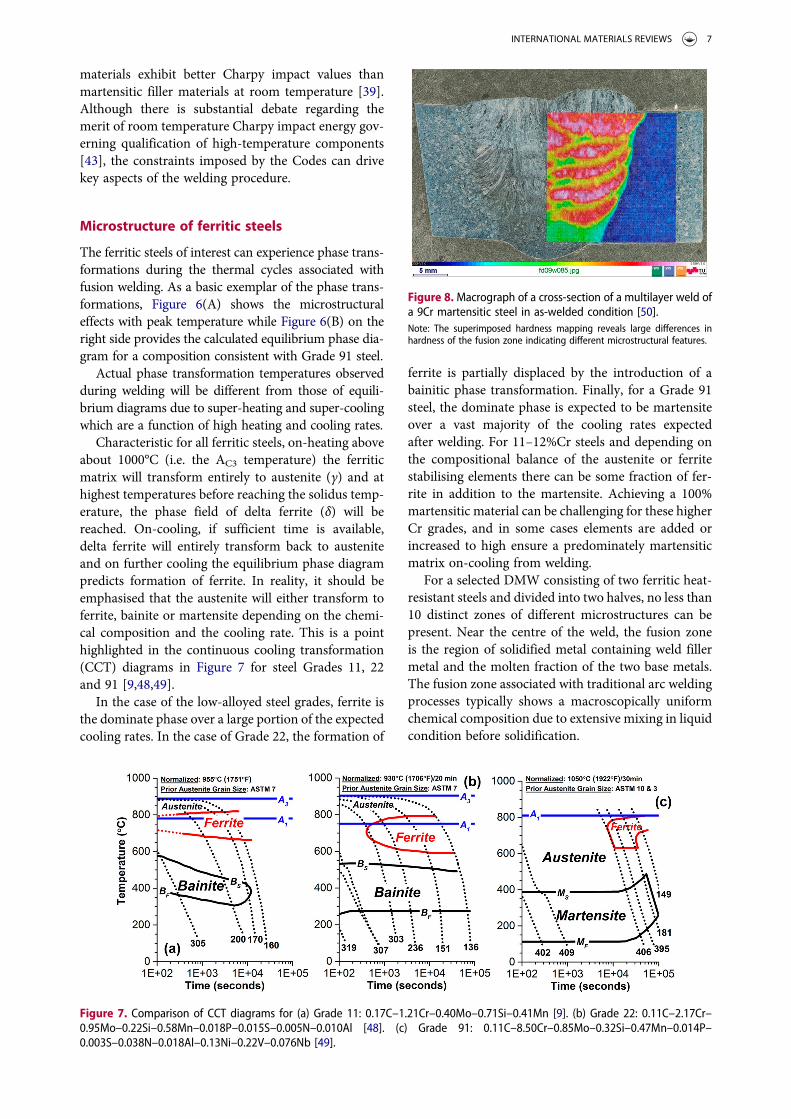
Figure 8. Macrograph of a cross-section of a multilayer weld ofa 9Cr martensitic steel in as-welded condition [50].Note: The superimposed hardness mapping reveals large differences inhardness of the fusion zone indicating different microstructural features.
INTERNATIONAL MATERIALS REVIEWS 7

The cross-section in Figure 8 shows a 9Cr multi-pass weldment made with matching filler metal andanalysed in ‘as-welded’ condition.
On the right side of the macrograph image, a hard-ness map has been superimposed. This form of hard-ness map reveals the heterogeneity in the as-deposited structure resulting from re-transformationand tempering. The ‘as-solidified’ weld metal micro-structure is not uniform for multi-layer welds. Threezones in the weld metal can be distinguished on thebasis of prior austenite grain (PAG) type, size andhardness measurements: columnar, fine equiaxedregions and very fine equiaxed regions, Figure 9.
With regard to the PAG size, these three regions cangenerally be classified where the columnar region has aPAG size >>40 µm, the fine equiaxed region has aPAGB size between 30 and 40 µm and the very fineequiaxed region has a PAG size <10 µm. There existsa fourth region unique to the as-deposited weld metalregion. It is a region of immediate transition betweenthe filler metal and base material where incompletemelting and mixing occurs.
In the HAZ, the materials of interest will normallycontain six basic regions. These are typically identifiedby peak temperatures introduced by the welding ther-mal cycles which have a direct influence on the micro-structure present. These specific regions in relationshipto Figure 6 are described in Table 4.
Example images for Grade 92 steel, obtained usingelectron back-scatter diffraction (EBSD) are providedin Figure 10.
Itmust be noted that in the overwhelmingmajority ofcases where ferritic to ferritic DMWs are made using ofarc welding processes, the weldment contains a complexcombination of HAZs which depend on the specifics ofthe thermal cycle and the pre-welding microstructuralcondition. Although the use of Figure 10 and Table 4is instructive, the reality is that the various HAZ regions
in Table 4 are subjected to multiple thermal cyclescreating a number of additional HAZ regions.
In metallurgically complex CSEF steels such asGrade 91 complete characterisation requires theuse of advanced metallographic techniques. Work ison-going to properly define the different HAZ micro-structures for 9Cr steels using an approach that is notborrowed from the zones identified for bainitic steelgrades. Such work has recently been detailed in [52]and has defined three distinct regions for a singlepass weld made in a 9Cr CSEF steel: the completelytransformed HAZ (CT-HAZ) where the peak tempera-ture is >AC3, partially transformed HAZ (PT-HAZ)where the peak temperature is between the AC1 andAC3 and an over-tempered HAZ (OT-HAZ) wherethe peak temperature is below AC1. Clearly in multi-pass welds a number of more complicated scenariosoccur and increase the number of zones that can beobtained in the HAZ. These regions have not beendefined on the basis of EBSD or grain size, but onthe dissolution of carbides in each region, Figure 11.
Because the solubility of carbon in ferrite is low,there exists a need to appreciate the initial microstruc-ture in the parent material and how this is altered bythe imposed welding thermal cycle and/or PWHTthermal cycle. This is important to this manuscriptas the migration of carbon is not dictated by thepresence of free carbon only but also by the dissol-ution of carbides and creation of free carbon formigration. It is thus the case that the migration ofcarbon in the dissimilar materials will ultimatelydictate the stability of the microstructure and withrespect to the type of carbides which are stabilised ineither the HAZ or weld.
Figure 9. An Example of the heterogeneity in as-depositedE9015-B9 filler metal showing at least three distinct regions [51].Note: The columnar region is highlighted in Region 1. The equiaxed regionsare subdivided into fine equiaxed (Region 2) and very fine equiaxed regions(Region 3)
Table 4. Descriptions of unique regions in the heat affectedzone of ferritic steels [47].Region Temperature range Characteristics
CGHAZ Tp ≥ 1250°C Complete re-austenisation ofthe original matrix, PAGBsize in the range of >40 µmand complete dissolutionof secondary precipitates
Grain growth region(often combinedwith the CGHAZ)
1250 < Tp < 1000°C Complete re-austenisation ofthe original matrix + PAGBsize in the range of 30–40 µm and near completedissolution of secondaryprecipitates
FGHAZ 1000 < Tp < 900°C Complete re-austenisation ofthe original matrix + PAGBsize in the range of <10 µmand incomplete dissolutionof secondary precipitates
ICHAZ 900 < Tp < 850°C Large scale transformation isinitiated in the bulk matrix.Incomplete dissolution ofsecondary precipitates
Initiation of Re-austenisation in HAZ
850 < Tp < 830°C Large scale transformation isinitiated at PAGBs
Subcritical ortempered HAZ
Tp < 830°C Original HAZ matrixundergoes softening dueto tempering but no largescale transformation
8 P. MAYR ET AL.

Carbon migration
Time dependent, thermally activated changes in car-bon level (carbon migration) is very important sincelocal carbon levels are critical to local microstructureand properties. In the extreme, carbon migration canbe seen due to the formation of a CDZ and carbon-enriched zone (CEZ). However, even in sampleswhere no microstructural changes are revealed usinglight optical metallography there can exist complexchanges that are not easily detectable. One of the classicexperiments examining the effect of alloying contenton carbon migration is that of Darken [53]. In hisstudies, Darken experimented with diffusion-bondedsteels containing different concentrations of C, Si,Mn and Mo and held these material couples in the aus-tenitic phase field at 1050°C (1922°F) for around 14days. In one material combination where the initialcarbon content in each material was nominally thesame (0.49 and 0.45 wt-%), the ‘uphill’ diffusion of car-bon occurred in the region of the diffusion bond from alocal carbon content of 0.315–0.586 wt-%, Figure 12.
This observation was notable in that the carbon haddiffused from the higher Si steel to the lower Si steelgiving rise to the reported carbon imbalance.
The driving force in an isothermal diffusion processmay be regarded as the negative gradient of the chemical
potential (partialmolal free energy) of the diffusing sub-stance. For a system of more than two components it isno longer necessarily true that a given element tends todiffuse toward a region of lower concentration gradienteven within a single phase region. Concentration gradi-ent and the chemical potential gradient, or activity gra-dient, may be of different sign, thus giving rise to ‘uphill’diffusion. Darken’s observations were important as theyrepresent one of the first studies examining the effect ofcarbon migration in dissimilar steels and laid the foun-dation for key follow-on studies including those ofChristoffel and Curran [3].
Christoffel and Curran [3] expanded on Darken’sexperiments to examine a wider range of material com-binations including ferritic to ferritic and ferritic toaustenitic materials for sub-critical PWHT thermalcycles. The detailed study included PWHT of DMWsin the range of 593–704°C (1100–1300°F) and fortimes between 25 and 3000 h. In their series of exper-iments, they proposed one of the first explanationsregarding the concentration of carbon across a dissim-ilar interface, Figure 13 and provided below:
(i) Carbon in solution migrates across the fusion linefrom the low-alloy steel to the high-alloy steel.The primary driving force for carbon migrationis the alloy content (such as Cr) resulting in a
Figure 10. Electron back scatter diffraction images for each of the regions in the heat affected zone.Note: Material shown in this Figure is Grade 92 [51].
Figure 11. Comparison of the dissolution of carbides in the heat affected zone of a grade 92 steel for simulated peak temperaturesof 1250, 1000, 900 and 830°C [51].
INTERNATIONAL MATERIALS REVIEWS 9

lower energy for carbon in the high-alloy steel ascompared to that of the low-alloy steel. This mag-nitude can be measured by the difference in car-bon concentration on the high-alloy and low-alloy sides of the fusion line (CE-CD).
(ii) The migration of carbon to the high-alloy steelincreases the carbon concentration on this sideof the fusion line and will result in the precipi-tation of carbides if the carbon concentration isabove the solubility limit. The added carbonresults in a carbon concentration gradient andcarbon will tend to migrate away from the fusionline under the influence of this gradient (CE-CA).
(iii) The carbon which has crossed the fusion linereduces the concentration of the carbon in sol-ution in the low-alloy steel. This results in a car-bon concentration gradient in the low-alloy steel(CC-CD). The carbon diffuses to the fusion line
in the low-alloy steel under the action of the con-centration gradient.
(iv) When the carbon concentration in the low-alloymaterial has dropped below the solubility valueby virtue of the migration across the fusion line,the carbides in the low-alloy steel begin to breakdown and carbon goes into solution to bring thecarbon level in solution back up to its solubilityvalue at this point. Note that carbon can onlymigrate when in solution and is not mobile inthe matrix when in the form of a carbides.
These first experiments were extremely importantbecause they highlighted that carbon migration is afunction of no less than three critical considerations:
1. Amount of free carbon in the matrix; an inherentproperty to the material(s) of interest.
2. Barrier to break down existing carbides to introduceadditional free carbon in the matrix; primarily con-trolled by the welding and applied PWHT.
3. Rate of carbon migration; controlled by the tempera-ture and timeduringPWHTand/or service operation.
In subsequent research, and as materials havebecome more complex leading to controlled additionsof Ti, V, Nb, N and other alloying elements, a fourthconsideration needs to be considered – resistance torecrystallisation of ferrite grains [30,31]. This is pri-marily controlled by the stability of the carbides pre-sent. Stable carbides will ‘tie up’ the available carbonand will pin grain boundaries and prevent recrystallisa-tion and grain growth. For example, where materialsmay have purposeful additions of V, Nb and N, the for-mation of MX precipitates which do not readily dis-solve in service and precipitate during PWHT canprovide added resistance to grain growth.
Figure 12. Carbon distribution in welded specimen of steels with similar carbon content and differing Si content after 13 days at1050°C revealing uphill diffusion of carbon experimentally observed by Darken in 1949 [53].
Figure 13. The carbon distribution across a DMW fusion line [3]where CA = original total carbon content in high alloy material;CB = original total carbon content in low alloy material; CC =carbon solubility concentration in low-alloy material; CD = car-bon content in low-alloy material at the fusion line; CE = car-bon content in high alloy material at the fusion line.
10 P. MAYR ET AL.

These primary considerations, highlighted by anumber of studies over the last 60 years, will bereviewed in the following sections. As will be discussed,many studies examining carbon migration in ferriticDMWs rely only upon light microscopy and/or hard-ness evaluation for establishing the extent of carbonmigration during welding, PWHT or service exposure.This evaluation may lead to inaccurate conclusionssince there are inaccuracies associated with thesemethods including interpretation of the data, etchingeffects, resolution of the technique and other issues.Although quantitative techniques, such as wavelengthdispersive X-ray spectroscopy (WDX) or energy-dis-persive X-ray spectroscopy (EDS) are more relevantto the examination of carbon migration, it is onlyrecently that these methods have been capable(especially in the case of EDS) of resolving carbon con-tents at least semi accurately.
Influence of fabrication on microstructuralevolution
For DMWs with differential alloying additions of Cr,the carbon will diffuse from the low Cr side to thehigh Cr side. To a lesser extent, minor alloying and car-bide-forming elements can drive carbon migrationincluding elements like Nb and V. Main influencingfactors for this diffusion governed process are timeand temperature including the effect of welding,PWHT and service exposure. These effects are of con-cern in following sections.
Influence of welding on carbon migration
The fusion line of DMWs is of highest interest as in thislocation, by the nature of fabricating DMWs, the stee-pest gradient in chemical condition can be found. Lun-din et al. [2,54] investigated a simple bead-on-plateweld in which a 9Cr–1Mo filler was deposited on a2.25Cr–1Mo base metal plate by the gas tungsten arcwelding (GTAW) process. In this examination, theelemental distribution was investigated across thefusion line in the as-welded and PWHT condition at
730°C (1350°F) for times ranging from 1 to 64 h. Inthe as-welded condition, a sharp difference in Cr con-tent across the fusion line of the 2.25Cr–1Mo/9Cr–1Mo weld can be observed while there is no differencein Mo, Mn and Si contents, Figure 14.
The results of the electron micro probe analysis(EMPA) of the Cr content reveal a steady transitionfrom 2.25Cr–1Mo to 9Cr–1Mo within a distance ofapproximately 0.2 mm. On the basis of light-opticalmicroscopy and hardness measurements there wasno evidence of migration of carbon after welding(Figures 15 and 16) and consistent with observationsmade by other researchers [56].
The fusion line and HAZ for a weldment between1CrMoV and 12CrMoV base metals welded with5CrMoV and 12CrMoV weld metal was analysed forcarbon migration in [57]. In Figure 17(A,B), a com-parison in hardness measurements made across thefusion line between the 1CrMoV and filler metals(Figure 17(A)) is compared to an identical procedurefor that of the 12CrMoV fusion line (Figure 17(B)).
In general, it can be stated that there is not a notice-able increase or decrease in the local hardness measure-ments suggesting that on the basis of hardnessmeasurements there is not gross migration of carbonacross either investigated fusion line.
Figure 14. Elemental distribution across a DMW between a2.25Cr–1Mo base material and a 9Cr–1Mo filler metal and inthe as-welded condition [55].
Figure 15. Light optical microscopy image of the fusion line ina DMW between a 2.25Cr–1Mo base material and a 9Cr–1Mofiller metal and in the as-welded condition [56].
Figure 16. Vickers hardness values across the fusion line in aDMW between a 2.25Cr–1Mo base material and a 9Cr–1Mo fil-ler metal and in the as-welded condition [56].
INTERNATIONAL MATERIALS REVIEWS 11

In work of Kozeschnik et al. [58,59] a thick-section,multi-pass weldment made in 2.25Cr–1Mo base metalwith 9Cr–1Mo weld metal was investigated. Unlike inthe investigations performed by [55–57] measured car-bon profiles across the fusion line using WDX revealedpartitioning of carbon in the as-welded state, Figure 18(A,B). The micrograph in Figure 18(A) shows the for-mation of a carbide depleted zone on the left side of thefusion line in the low-alloyed 2.25Cr–1Mo steel and a∼20 µm wide carbide seam is clearly visible in the9Cr–1Mo weld metal.
The results in Figure 18(B) emphasise the importanceof representative weldments and techniques to effec-tively assess the influence of the welding process on car-bon migration. This Figure provides an assembly of 15WDX carbon line scans across the fusion zone that con-firms the occurrence of carbon partitioning. This diffu-sion-governed effect is more pronounced as a multi-layer weld is investigated so that the material has experi-enced several elevated temperature weld thermal cycleswhich have increased the carbon activity and migration.
Although there appears to be a disagreement amongthe literature regarding the influence of the welding
thermal cycle on carbon migration, there is reason tobelieve that welding thermal cycles can have a signifi-cant impact on the formation of a CDZ and CEZ in aDMW. For example, it will be shown in the followingsection that the welding process can have a dramaticeffect on the local carbon migration following a man-datory PWHT due to the refinement that occurs in acomplex multi-pass weld.
Influence of PWHT on carbon migration
The effect of PWHT clearly enhances the partitioningof carbon and is evident in Figures 19–21. In Figure 19,the micrograph shows the fusion line between a2.25Cr–1Mo base metal and a 9Cr–1Mo weld metalfollowing PWHT at 732°C (1350°F) for 64 h [55].
The width of the CDZ increases with additional timeat temperature, a point highlighted by the series ofimages shown in Figure 20 [56].
A comparison of PWHT at 750°C (1382°F) is pro-vided for times of 1, 2 and 10 h effectively showingthis growth within the 2.25Cr–1Mo base material andadjacent to the fusion line. An ex-service weldment
Figure 17.Micro-hardness profiles across the cross-section of aDMW give a first indication of the microstructural changes inthe fusion line area. Hardness in the HAZ is mainly influencedby the chemical composition of the base materials, especiallythe carbon content, but also the welding parameters appliedand the resulting thermal cycles. Their influence can beobserved in Figure 18 [57].
Figure 18. Optical micrograph of the fusion line between a 2.25Cr–1Mo base metal and a 9Cr–1Mo weld metal in the as-weldedcondition (A) and corresponding carbon profiles obtained by wavelength dispersive X-ray analysis (WDX) analysis revealing parti-tioning of carbon during welding (B), adapted from Ref. [58].
Figure 19. Light optical micrograph of 9Cr–1Mo weld metaldeposited by the GTAW process on 2.25Cr–1Mo base metaland following PWHT at 732°C (1350F) for 64 h revealing severecarbon migration [55].
12 P. MAYR ET AL.

between T22 and T91 installed in a reheater section of asupercritical boiler is shown in Figure 21.
The CDZ is clearly visible in the T22 along the entirelength of the fusion line where the carbon has migratedfrom the low-alloy T22 to the higher alloy filler metal(i.e. filler metal is matching to the T91 material).
The effect of PWHT on the measured width of theCDZ is provided in Figures 22–24. The fusion line ina weldment between a CrMoV bainitic steel and a5Cr and 12Cr weld metal were investigated followingPWHT at 730°C (1346°F) for 2 h, Figure 22 [57].
In this example, there are similar trends in the for-mation of a CDZ and a CEZ. Where the 1CrMoVsteel was welded with the higher Cr-content fillermetal (12CrMoV), the peak in the CEZ appears to bemore pronounced.
In Figure 23, the results in [57] were evaluated for a12CrMoV filler metal deposited on a 1CrMoV basemetal for PWHT thermal cycles of 680°C (1256°F)for 2 h and 730°C (1346°F) for 10 h. In this compari-son, the effect of the higher temperature and time areclearly demonstrated where the absolute peak in car-bon and the width of the CEZ are more distinct.
Kozeschnik et al. [58] investigated the influence offiller metal on the measured and simulated carbonmigration. In their results, the authors identified aclear effect following a PWHT cycle, Figure 24(A,B).In these examples, the effect of the Cr gradient andmandatory PWHT cycle to that of the Grade 91 con-stituent is clear. In this example, the deleterious for-mation of the CDZ is a direct result of thecombination of welding and PWHT.
Anand et al. [60] showed the influence of a 9Cr–1Mo weld metal against a 2.25Cr–1Mo base metal fol-lowing a relatively modest PWHT at 650°C (1202°F)for 1 and 50 h using EMPA, Figure 25. The trend inthe measured carbon content is similar to that of thepreviously detailed results.
Lundin [55] observed that in the fusion zone ofbead-on-plate welds in which a 9Cr–1Mo weldmetal was deposited on a 2.25Cr–1Mo base metalplate by means of GTAW, the formation of a CDZstarted in the overlapped HAZ region between thefirst and the second weld pass after a PWHT at732°C (1350°F) for 1 h. He concluded that due to
Figure 20. Representative images of the fusion line between a 9Cr–1Mo weld metal and 2.25Cr–1Mo parent metal showing the CEZ(“ppt zone’) and the CDZ (‘soft zone’) for [56]: A – 750°C (1382°F) for 1 h; B – 750°C (1382°F) for 2 h; C – 750°C (1382°F) for 10 h.
Figure 21. Ex-service T22 to T91 weldment operating in areheater section after 45,000 h at service temperature (>565°C, 1050°F).Note: This weldment was made using filler metal matching to the T91 andunderwent a PWHT prior to entering service. The minimum hardness in thecarbon denuded region is ∼100 HV 0.5.
Figure 22. Effect of PWHT (730°C/2 h) on the migration of car-bon at the fusion line in a ferritic to ferritic DMW between a 1%CrMoV parent material and either 5%Cr or 12%Cr weld metal[57].
INTERNATIONAL MATERIALS REVIEWS 13

multiple thermal cycling the accumulative phasetransformations in this region reduced the grain sizecompared to other regions adjacent to the fusionline in the base metal. Through grain boundaryrefinement, carbon atoms migrate faster in this regiondue to a higher fraction of grain boundaries com-pared to coarse-grained structures. Lundin estimatedthat the diffusion in the fine-grained overlap regionis about an order of magnitude faster than that inthe coarse-grained region. Figure 26 shows opticalmicrographs of the weld configuration and the firstsigns of decarburisation in the HAZ in the overlapregion between the first and second pass. This workhighlights the importance of PWHT and of the effectthat multi-pass weld thermal cycles can have in theformation of CDZ and CEZ in a DMW.
Influence of service exposure on carbonmigration
There are relatively few studies which examine theeffect of carbon migration during service at
temperatures that are lower than conventionalPWHT. This is an important clarification becauseDMWs may be expected to operate for durations inthe 100,000s of hours and for conditions that are likelynot directly relevant to PWHT.
Different PWHT temperatures and timeswere inves-tigated in Ref. [57] showing the general trend thatincreases in temperature and time increased the widthof the CDZ, Figure 27. In this study, weldments whichwere given different PWHT thermal cycles were sub-sequently exposed at 550°C (1022°F) for times rangingfrom2000 to 10000 h. Interestingly, thewidths of decar-burised zones differing after welding or PWHT begin tomerge for the longest investigated duration at 550°C(1022°F). emphasising the importance of long-term ser-vice on formation and growth of the CDZ in DMWs.
Simulation of carbon migration
Owing to the difficulty in accurately measuring theCDZ and CEZ in a given DMW as well as the durationsoften required to develop meaningful results (such aslong-term aging at service temperatures), the matu-ration of thermal models to describe the formation ofthe CDZ and CEZ in dissimilar metal couples has
Figure 23. Effect of PWHT (680°C/2 h and 730°C/10 h) on themigration of carbon at the fusion line in a ferritic to ferriticDMW between a 1%CrMoV parent material and 12%Cr weldmetal [57].
Figure 24. (A) Characteristic micrograph of the fusion line between a 2.25Cr–1Mo and 9Cr–1Mo weld following PWHT at 750°C(1382°F) for 4 h and service exposure to 580°C (1076°F) for 10,000 h. [58]. (B) measured redistribution of carbon in a 9Cr–1Moand 2.25Cr–1Mo weld following PWHT at 730°C (1346°F) for 3 h and service exposure to 580°C (1076°F) for 10,000 h [58].
Figure 25. Effect of time (1 and 50 h) at temperature (650°C,1202°F) for a DMW between a 2.25Cr–1Mo base metal and9Cr–1Mo weld metal. Measurements made using the EMPAquantification method [60].
14 P. MAYR ET AL.

been particularly helpful. Initial approaches to model-ling the diffusion of carbon in ferritic DMWs wasbased on the classical experiments by Darken[53,61,62]. As discussed previously in the Christoffeland Curran experiments, the carbon diffusion in ferri-tic DMWs is far more complex than originallysuggested. The complexity is associated with a numberof factors that must be resolved:
(i) At elevated temperature, such as during weldingthermal cycles or normalisation, the materialsmay be face-centred-cubic (FCC). However,during PWHT or service the materials are body-centred-cubic (BCC).
(ii) There is little free carbon in ferritic BCC systems.In mild steels, the carbon is precipitated ascementite. In low-alloy steels, the carbon maybe present in a number of carbides such asM23C6 or M2C and in high strength CSEF steels,the carbon may be present as M23C6, M6C or MX.The dissolution of these phases is an importantconsideration in the lower chromium materialto create the necessary ‘free carbon’ for migration.
(iii) Absorption of carbon and formation of carbidesin the higher chromiummaterial. As carbon satu-rates, the higher chromium constituent and car-bides begin to precipitate, the migration ofcarbon slows with increasing time at temperature.
The authors in Refs. [63,64] considered non-para-bolic kinetic relationships for calculating the extent ofcarbon migration using a discrete particulate modelfor diffusion in a 2.25Cr–1Mo to mild steel weldmentand at applied PWHT temperatures of 620 and 700°C. This approach was chosen so as to accommodatethe dissolution and re-precipitation of carbides andthe non-parabolic nature of the carbon migration pro-cess. A depiction of the discrete particulate model isprovided in Figure 28.
A comparison of this approach to actualmeasurementsis provided in Figure 29. It can be seen that the modellingunder-estimates the extent of diffusion for both of theinvestigated PWHT temperatures, e.g. at 700°C after40 h the width of CDZ is about 2.5 and 0.8 mm for themeasurement and the simulation, respectively.
To adequately describe and account for this com-plex behaviour, researchers commonly use CALPHADtools such as DICTRA [65] and MatCalc [66]. Theirmodels are based on ternary diffusion, first describedby Christoffel and Curran in [3] and subsequentlyexamined in several papers [57,67–70].
Figure 26. Light optical micrograph of 9Cr–1Mo weld metaldeposited by the GTAW process on 2.25Cr–1Mo base metaland following PWHT at 732°C (1350F) for 16 h revealing loca-lised carbon migration in overlapped weld bead regions inthe heat affected zone of the 2.25Cr–1Mo base metal [55].
Figure 27. Effect of PWHT on the width of the decarburisedzone in a ferritic to ferritic DMW between 1Cr–1Mo–0.25Vand 12Cr–1Mo–0.25V base metals. In this figure, the fillermetal is 12Cr filler metal [57].
Figure 28. Schematic for the discrete particulate model todescribe carbon migration in ferritic to ferritic DMWs [63].
INTERNATIONAL MATERIALS REVIEWS 15

The authors in Ref. [69] measured the carbonmigration across the fusion line of a weldment madebetween 2.25Cr–1Mo base metal and a 12Cr weld metalusing EMPA. The results of the simulation for carbonmigration across the fusion line are in excellent agree-ment with the results of the measurement, Figure 30.
In utilising the baseline weldment to examine thevalidity of the results, the researchers extended thesimulations to examine the effect of PWHT tempera-ture on the extent of carbon migration, Figure 31.
The effect of PWHT is shown in this Figure to bequite profound on the formation and growth of theCDZ and CEZ.
A recent publication compared the methods formeasuring CDZ in a Grade 22 to Grade 91 DMWmade using E8015-B8 filler material, Figure 32.
The weldment of interest was provided from an ex-service Grade 22 to Grade 91 weld using 9Cr–1Mo(E8015-B8) filler metal. The final weld (cross sectionshown in Figure 5) was given a PWHT at 740°C for2 h and then operated in service at 570°C for79,000 h [5]. The calculated width of the CDZ and
CEZ determined using MatCalc is compared with theresults for measurements made using light microscopy,EMPA and a low-load hardness traverse across thefusion line. As shown in the figure, the results formeasured carbon values using EMPA and calculationsare in reasonable agreement, whereas the lightmicroscopy vastly underestimates the size of theCDZ. The hardness traverse is reliant upon properinterpretation and may provide a better estimate ofthe CDZ as opposed to light microscope alone.
The ability to simulate carbon migration withreasonable accuracy has produced a number of relevantpublications which examine the effect of alloying con-tent on carbon migration [68,71]. In Figure 33, a com-parison is shown between several steels and for PWHTor service conditions [71].
In some instances, the effect of PWHT may not be asgreat as that of service exposure and vice versa due to thepotential for phase transformations within the PWHTrange (such as for MS and CrMoV). In cases wherethe material does not transform to austenite at the statedPWHT temperature, such as for P91, the carbon activity
Figure 29. Measured width of the carbon-denuded zone at 620 and 700°C using optical microscopy (a) and calculated width of thecarbon-denuded zone at 620°C and 700°C using the developed model in [63]. Note the difference in the y-axis scale for each graph.
Figure 30. Comparison of EMPA results to a simulation for carbon migration. The multi-pass weldment of interest was madebetween 2.25Cr–1Mo base metal and 12Cr weld metal and given a PWHT of 750°C (1382°F) for 2 h [69].
16 P. MAYR ET AL.

is changed by ∼an order of magnitude at the statedPWHT temperature of 750°C (1382°F).
The influence of the alloying content includingchromium and carbide formers on the carbon activityat 600°C (1112°F) is plotted in Figure 34 [68].
Notably, the carbon activity decreases with eitherdecreasing carbon content and/or the presence of car-bide-forming elements in the matrix. In the case ofP22, the influence of carbon content is notable inthat a carbon increase of ∼2X (from 0.07 to0.15 wt-%) increases the carbon activity by a similarfactor. Furthermore, the addition of carbide formersto the P22 such as in compositions consistent with
P23 (Nb and V) and P24 (Ti and V) reduces the car-bon activity by ∼50%.
To show the effect of chromium on behaviour, theauthors examined a composition for Grade 91 steeland only varied the chromium content from 2.5 to8.5 wt-%weight percent, Figure 35 [68].
Within this range, the carbon activity at 600°C(1112°F) was changed by at least an order of magni-tude. The formation of deleterious regions in a ferriticto ferritic DMW is a continued trend irrespective ofthe materials of interest. In summary, the carbonactivity is affected by a function of no less thanfour key variables:
Figure 31. Effect of PWHT temperature on carbon migration in a 2.25Cr–1Mo to 12Cr weldment for 2 h [69].
Figure 32. Comparison of the simulated carbon migration in a 2.25Cr–1Mo (P22) to 9Cr–1Mo (E8015-B8) weldment to differentmeasurement techniques: (A) results for MatCalc simulation; (B) EMPA measurement across fusion line; C – light microscopymeasurement of CDZ at fusion line; (D) microhardness (HV 0.05) measurements across fusion line.
INTERNATIONAL MATERIALS REVIEWS 17

(i) Alloying content such as the differencein chromium and carbo-nitride formingelements;
(ii) Number of thermal cycles during welding;(iii) PWHT temperature and time at PWHT;(iv) Service temperature and time in service.
High-temperature performance in creep
In simple uniaxial creep tests, the performance of agiven DMW is generally controlled by the rate or
extent of carbon migration in the composite structureand the constraint provided by the filler material. Intwo separate studies, the effect of the weld metalstrength was examined in the performance of Grade22 to Grade 91 and of Grade 23 to Grade 91 DMWs[72–74], Figures 36 and 37.
In these studies, the life of the DMW was increasedthrough the use of the higher strength filler metal (i.e.matching to Grade 91). This increase in behaviour canbe explained by the increased constraint that the stron-ger filler material provides. The use of a weaker fillermaterial allows for more uniform stress distributionand has the effect of shortening the life of theweldment.
The influence of PWHT on the performance ofDMWs can be shown in the data provided in Figures 38and 39 and Table 5.
The application of a PWHT at 746°C (1375°F) for2 h had a significant influence in the failure time andfailure location of a ferritic DMW where a weld repairwas performed in a P91 component using a E9015-G(Grade 23) filler metal [33]. The triangles in Figure 38are data for the weldment given a PWHT while the cir-cles are data for the weldment in the as-welded state. Itcan be observed that the tests which were not given aPWHT always exceeded the life of those where
Figure 33. Comparison of the carbon activity for variousmaterials at a PWHT temperature of 750°C (1382°F) and a ser-vice temperature of 600°C (1112°F).Note: MS = Mild Steel, CrMoV = 0.5Cr–0.5Mo–0.25V, T25 = 2Cr–0.3Mo–0.25V, P91 = 8.5Cr–1Mo–0.25V [71].
Figure 34. Calculated carbon activity values for carbon, lowalloy and CSEF steels and at a service temperature of 600°C(1112°F) [68].
Figure 35. Calculated carbon activity values for a P91 steelcomposition with variation only in the chromium contentand at a service temperature of 600°C (1112°F) [68].Note: P91 = 8.5%Cr, 0.88%Mo, 0.23%V, 0.40%Mn, 0.43%Si, 0.1%Ni, 0.018%Nb, 0.045%N.
Figure 36. Uniaxial creep results using a Larson Miller par-ameter comparison for a DMW between Grade 22 and Grade91 using filler metal matching to either parent metal constitu-ent [72,75].
Figure 37. Uniaxial creep results using a Larson Miller par-ameter comparison for a DMW between Grade 23 and Grade91 using filler metal matching to either parent metal constitu-ent [73,74,76].
18 P. MAYR ET AL.

PWHT was applied. This behaviour was true for creeptests at both 600 and 625°C (1112 and 1157°F) and fortimes up to ∼15,000 h.
Furthermore, and as shown in Figure 39, thebehaviour in the cross-weld creep failure supportsthis observation as the samples given PWHT failedalways at the fusion line (Figure 39(B)) while thesamples test in the as-welded condition exhibiteddamage in both the Grade 91 HAZ and at the fusionline between the Grade 91 parent metal and E9015-Gfiller metal. This behaviour is best depicted by themixed-mode failure through the fusion line and theGrade 91 HAZ in Figure 39(A). The behaviour inFigure 39(A) suggests that the damage mechanismsresponsible for failure are in direct competitionwhere PWHT is not purposely applied (such as in aweld repair scenario). Damage in DMWs is oftenreported as being in the CDZ [2]. In some cases,
and as depicted in Figure 40, maximum damage isadjacent to the CDZ.
Tearing at the end of uniaxial tests or in the case of acomponent failure mask this behaviour since it can bedifficult to identify the exact crack path or examineadvanced stages of creep damage before failure occurs.In uniaxial crossweld tests where only one fusion line isexamined (either as a consequence of a small gaugelength or a multi-component weldment), it is imposs-ible to evaluate the evolution of damage unless inter-rupted tests are conducted. In the case of Figure 40,the observation of damage in a region adjacent to theCDZ introduces a second important consideration inthe performance of steels at high temperature –damage tolerance.
The issue of damage tolerance is most easily dis-cussed in the context of creep ductility. In the case ofthe CDZ, and although it exhibits a significantlyreduced strength, it possesses very high creep ductility.Since it is supported by surrounding parent or fillermaterial, it sheds strain to the adjacent microstructure.
Figure 38. Uniaxial test creep results for novel, large specimenfeature creep tests using a Larson Miller parameter comparisonfor a dissimilar repair weld made in grade 91 steel using E9015-G (Grade 23) filler metal [41]. See Table 5 for test conditionsand results.
Figure 39. Example of failures in Figure 38 for sample withoutPWHT 6B-1 (A) and sample with PWHT 7B-1 (B) [41]. See Table5 for test conditions and results.
Table 5. Relevant and potential DMW combinations wheregrade 22 (2.25Cr–1Mo) and Grade 91 (9Cr–1Mo–VNbN) mustbe welded [41].
SpecimenaWelding
procedureb,cTest
conditionsTime torupture Failure location
6A-1 E9015-G (Grade23), MethodA
625°C/80 MPa
3049 h Fusion line(weld side)HAZ damagenoted
6A-2 600°C/80 MPa
13,994 h PredominatelyHAZfusion linedamagenoted
7A-1 E9015-G (Grade23) Normal +Typ. PWHT(746°C, 1375°F/2 h)
625°C/80 MPa
2314 h Fusion line(weld side)
7A-2 600°C/80 MPa
9442 h Fusion line(weld side)HAZ damagenoted
6B-1 E9015-G (Grade23), MethodA
625°C/80 MPa
4535 h Mixed mode;HAZ &fusion line(weld side)
6B-2 600°C/80 MPa
12,362 h Fusion line(weld side)HAZ damagenoted
7B-1 E9015-G (Grade23) Normal +Typ. PWHT(746°C, 1375°F/2 h)
625°C/80 MPa
1326 h Fusion line(weld side)
7B-2 600°C/80 MPa
7347 h Fusion line(weld side)HAZ damagenoted
Note: Descriptions accompany Figures 39 and 40.aThe ‘A’ series welds were fabricated in ex-service Grade 91 steel material.The ‘B’ series welds were fabricated in the same Grade 91 steel materialfollowing a normalisation and tempering heat treatment.
bMethod A involved a three-layer technique in accordance with [77,78] andthe shielded metal arc welding (SMAW) process, where the electrode sizewas increased for each of the butter layers against the weld excavation.Thus, the electrode diameters were as follows; layer 1 used 2.5 mm (3/32 in.), layer 2 used 3.2 mm (1/8 in.) and layer 3 used 4.0 mm (5/32 in.). The fill passes were performed using 4.0 mm (5/32 in.) electrodes.
cNormal procedure, the welding procedure was performed using theSMAW process with no specific guidance beyond normal ‘good practice’including 3.2 mm (1/8 in.) in root and 4.0 mm (5/32 in.) for remaining fill)to the guidance in Ref. [79].
INTERNATIONAL MATERIALS REVIEWS 19

Although the adjacent microstructure is stronger increep, it is less ductile and the strain is accommodatedby the formation of creep cavities. Eventually the cavi-tation becomes widespread through the thickness ofthe weld and micro-cracks are able to easily link andcause a rapid failure.
Performance of DMWs in service
Design recommendations do not typically take intoaccount the type or nature of the weldments presentin the component or system. Thus, it is normallyassumed that provided weldment fabrication is carriedout to accepted procedures and properties similar tothose of the parent will be achieved. This assumptionis rarely if ever valid since, even in situations wherethe composition of the welding consumables matchesthat of the parent, the thermal cycles associated withweld manufacture will lead to a heat affected zone inthe parent metal. The specific microstructural regionsdeveloped within the HAZ will depend on the alloysinvolved, details of the time and peak temperatureand the subsequent cooling rate. Weld metals are nor-mally selected to overmatch the room temperaturestrength of the parent metal(s) being welded. This
simplistic view does not take into account the modifi-cation of the parent material in the HAZ by the weldingthermal cycle, let alone consider the more complexscenario imposed by dissimilar parent materials and/or weld metal.
Failure in DMWs (in both ferritic to ferritic and fer-ritic to austenitic examples) often occurs as a conse-quence of design which does not properly take intoaccount cyclic operation. Indeed, the specifics of designand operation have caused different cracking modes inthick section piping welds in ½Cr½Mo¼V steel madewith 2.25Cr–1Mo. These issues will be detailed belowwhere the DMW either directly affected or did notaffect the final failure mode. This is important becauseit highlights the need to implement well-engineeredsolutions and to consider the end-use application inany design that requires a ferritic to ferritic DMW.
Damage classified as Type IV cracking has beenidentified in service weldments for more than 20years. It is apparent that existing weldments manufac-tured from creep resistant low-alloy steels are suscep-tible to this problem. Thus, most utilities haveintroduced assessment programmes involving plantinspection to monitor weld condition. The identifi-cation of creep cavitation and cracking then frequently
Figure 40. Example of damage in a dissimilar repair weld made in Grade 91 steel using E9015-G (Grade 23) filler metal [41]. SeeTable 5 for test conditions and results. (A) Macro image of failed creep specimen 6A-1; (B) image of fusion line failure; (C) image ofdamage at the unfailed fusion line. Note that the maximum level of damage is adjacent to the visible carbon-denuded zone and notwithin the carbon-denuded zone.
20 P. MAYR ET AL.

necessitates repair of service welds. Recent informationregarding the performance of ½Cr½Mo¼V steel weld-ments in UK power plant highlights the continuingneed for on-going repair strategies.
Classically, Type IV cracking develops as a conse-quence of creep cavitation initiated in the ICHAZand as provided in Figure 41(A,B). The circumferentialnature of the damage indicates that significant axialstresses must be present since creep damage occurspreferentially in orientations perpendicular to the prin-ciple stress direction. Thus, initially welds at greatestrisk of failure were located at terminal joints since atthese positions significant bending or tensile stressescould be developed for example due to problems withpiping supports.
The cracking shown in Figure 42 was initiated at theinside surface of a ½Cr½Mo¼V steel main steam pipe.This damage is a consequence of a thick (up to150 mm) structure that is at a uniformly low tempera-ture suddenly experiencing a rapid temperatureincrease. This is an ‘upshock’ thermal transient. If thethermal event is large enough, the surface in contact
with the steam is forced into compression as it attemptsto expand against the colder steel in the remainder ofthe wall thickness. Continued heating will result in agradual increase in the component temperature. Asthe temperature gradient reduces, the whole systemexpands, taking the inside surface into tension. Duringa period of steady operation at high temperature, thisresidual tensile stress relaxes by creep. In the½Cr½Mo¼V steel shown, the location of lowestcreep strength is in the weld heat affected zone andthe stress relaxation induces Type IV intergranularcracking. Characteristic features of this process are adistinctive shallow ‘skin’ of creep cavitation along theinside surface of the pipe, and some cavitation immedi-ately alongside the crack path itself [81]. Although thisform of damage has not been widely reported therehave been approximately 100 weld joints affected inpower plants in the UK, with the deepest crack extend-ing to around 50% of the wall thickness [81].
Cyclic creep relaxation damage is different to thethermal fatigue which arises as a result of cold downshocks in a relatively hot pipe. It was shown in [81]
Figure 41. Example of heat affected zone cracking attributed to type IV failure mechanism in a CrMoV weld made with 2.25Cr–1Mofiller metal [80]. (A) Macrograph of failure; (B) micrograph of failure location (not in the same weldment); (C) example of damagemorphology in the heat affected zone.
Figure 42. Example of cracking caused by an ‘Upshock’ ther-mal transient in a ferritic to ferritic DMW in a CrMoV weldmade with 2.25Cr–1Mo filler metal [74].
Figure 43. Example of cyclic creep relaxation cracking a ferriticto ferritic DMW in a CrMoV weld made with 2.25Cr–1Mo fillermetal [74].
INTERNATIONAL MATERIALS REVIEWS 21

that fatigue cracking was present at the inside surface ofpiping welds in more than half the large coal-firedstations in the UK (600–700 welds), Figure 43.
This problem was not directly linked to the fact thatthe joints used had DMWs. The cracks tended to befully circumferential and the deepest found approachedhalf wall thickness. In piping systems where crackswere found there was a tendency for the damage tobe more severe at the boiler end of the piping system.The fatigue cracks were a consequence of rapid steamchilling events. The thermal gradient between thecooler inside surface and the hotter outside surface cre-ated a transitory tensile stress on the inner surface ateach chilling event. The cracks initiated at local stressconcentrations at weld roots or at internal changes ofsection at counterbores. As is usual with thermal fati-gue, cracking is driven by stress and is independentof local microstructure. Because steam cooling isrequired to produce the necessary thermal stresses,crack tip growth may take place below normal operat-ing temperature [81].
More recently, damage has been identified in pipeweldments and in locations that would be expected tobe subjected to lower system loads. These obser-vations could then be interpreted in terms of thestress level present during creep. In general, lowerdeformation rates and longer lives would be expectedat lower values of applied stress. However, there aremany examples exist of apparently similar joints,operating under similar conditions, exhibitingdifferent behaviour. This is to say that some weldsoperating at nominally the same pressure and temp-erature developed cracks while others were defect-free. Moreover, in welds with a high degree of HAZrefinement, cracking adjacent to the fusion boundaryhas been observed, Figure 44(A–C) [82].
This damage, classified as Type IIIa, appears to berelated to time-dependent carbon diffusion which
reduces the creep strength in the HAZ adjacent tothe fusion boundary. The cracking detailed in theseimages is a directed consequence of the instability atthe fusion line that is induced by the ferritic to ferriticweldment. It is thus apparent that the local stress state,rather than simply the applied stress level, is the impor-tant factor governing component performance.
A classic example of poor practice is provided in[80] where a CrMoV stop/control valve (1.25Cr–1Mo–0.25V) was welded to a Grade 91 main steamline using a Grade 22 consumable (E9018-B3). In thisfailure, the valve was machined to a wall thickness ofnominally 76 mm (3 in.) and the Grade 91 pipe was40 mm (1.56 in.) in thickness, Figure 45. The operatingconditions of the heat recovery steam generator inwhich this DMW was installed were 565°C (1050°F)
Figure 44. Example of dissimilar weld metal cracking at the fusion line in a CrMoV weld made with 2.25Cr–1Mo filler metal [75]. (A)Macrograph of failure; (B) micrograph of failure location (not in the same weldment); (C) example of damage morphology in thecoarse-grained heat affected zone and directly adjacent to the fusion line.
Figure 45. Schematic of the welded ferritic to ferritic DMWbetween a P91 main steam pipe and a turbine control/stopvalue made of 1.25Cr–1Mo–0.25V. This failure occurred in<5000 h in a combined cycle natural gas plant operating at565°C (1050°F) and 12.4 MPa (1800 psi) [83].Note: image not to scale.
22 P. MAYR ET AL.

and 12.4 MPa (1800 psi). The failure occurred after<5000 h of operation.
As shown in Figure 46, the failure occurred alongthe fusion line between the Grade 91 and Grade 22 fil-ler metal in the failure detailed in Figure 45.
This is not unexpected, as carbon will migrate fromthe Grade 22 to the Grade 91 pipe and create a localCDZ in the Grade 22 filler metal at the fusion line andwhere failure occurred. In this example, the failure wasclearly exacerbated by the poor design whereby theGrade 22 was utilised as the filler material to the thinnerGrade 91 pipe. The best design is one that utilises a tran-sition piece, as shown in Figure 47. In cases where this isunfeasible, the secondary option would be to utilise a fil-lermaterialmatching to the thinnermaterial (in this caseE9015-B9, matching to Grade 91) so that the CDZ isplaced in the thicker material and subjected to a loweroperating stress. Note that for the provided pipe dimen-sions and operating conditions, the expected operatingstress on the CrMoV side of the DMW is at least 50%lower than that of the P91 side of the joint.
Conclusions
A continued increase in the demand for more efficientpower generation is necessitating the need to manufac-ture power plants, which can meet these aggressivedemands and naturally require the joining of dissimilarmaterials. The joining of DMWs introduces a complex-ity of fabrication issues, which must address the carbonmigration that may take place during welding, PWHTand service. Despite the challenges that exist in prop-erly fabricating and operating ferritic to ferriticDMWs, it should be emphasised that root cause isnot always directly linked to the evolution of the car-bon-denuded region on the lower alloyed steel side.
The performance of a structure is predicated onaddressing factors, which affect design, operation, fab-rication and metallurgy. For application-dependentscenarios, there may be clear solutions for thin-sectioncomponents (such as tubing) which are different fromthe recommendations made for thick-section vesselsincluding pipe or header constructions. Service con-ditions, which require cycling, may require more inno-vative approaches than those, which only mandatedesign for a baseload, constant load power plant. Thevariation in parent materials, which must be joined,may mandate an approach, which attempts to optimisethe balance of performance between the variousmaterial constituents.
It is often the case that in service failures occur as aresult of a compounding set of circumstances in thedesign, operation, fabrication and metallurgy ofDMWs. For example, DMWs are often located atthickness transitions, locations of higher in servicestress such as terminal points in piping and often fab-ricated in the field using less rigorous controls on eitherquality or inspection or both. These issues are oftenoverlooked due to design calculations that may suggesta welded connection should possess an infinite lifewhen in reality this simplistic approach should neverbe regarded as acceptable for in service performanceof DMWs. In this regard, there is a need to embraceconcepts, which can predict not only when the DMWwill fail, but also how the DMWmight fail in operation(e.g. emphasis on leak before break).
There exists a continued need to assess the behav-iour of DMWs with respect to metallurgical evaluation,mechanical testing and simulation (structural and met-allurgical). Little detail in the literature is availablewhich describes the metallurgical evaluation ofDMWs with respect to interrupted behaviour and forthe combined effect that temperature, time and straincan have on carbide dissolution and carbon migration.Mechanical testing is needed with respect to structural,feature-type and/or vessel tests, which provide relevantinformation regarding component failure. Simple uni-axial cross-weld creep tests, and particularly withregard to small diameter round bar geometries, are
Figure 46. Macro image of the cracked DMW between a P91main steam pipe and a turbine control/stop value made of1.25Cr–1Mo–0.25V. This weldment was fabricated using2.25Cr–1Mo filler metal [83]. (A) Macro sample; (B) micro-crack-ing ahead of the main body of the crack tip; (C) appearance ofthe main body of the crack.
Figure 47. Schematic of a proper design for DMWs where tran-sitions in thickness are necessary. Note that the use of a Grade91 transition piece places the DMW in the thicker componentand therefore at a much lower operational stress.
INTERNATIONAL MATERIALS REVIEWS 23

not sufficient to establish how a weldment might fail inservice. Structural simulation needs to address how toproperly model the influence of an assumed weak, car-bon-denuded region of material (and size) might haveon component behaviour. Finally, and with regard tometallurgical simulation, there is a need to improvethe quality of databases for thermodynamic and kineticsimulations. Especially with newer alloys containingsmall amounts of elements like boron, with a dedicatedinfluence on diffusion of elements and therefore micro-structural stability, databases need to be updated. Asthe number of developed materials continues toincrease and therefore the number of potential materialcouples similarly evolves it is important to considerhow these dissimilar materials behave under the influ-ence of operational and structural circumstances.
Disclosure statement
No potential conflict of interest was reported by the authors.
ORCID
Peter Mayr http://orcid.org/0000-0003-2530-4644
References
[1] DuPont JN. Microstructural evolution and high temp-erature failure of ferritic to austenitic dissimilar welds.Int Mater Rev. 2012;57(4):208–234.
[2] Lundin CD, Khan KK, Yang D. Effect of carbonmigration on the metallurgical structure and mechan-ical properties of Cr-Mo weldments. Recent trends inWelding Science and Technology. ASMInternational; 1990. p. 291–296.
[3] Christoffel RJ, Curran MR. Carbon migration inwelded joints at elevated temperatures. Weld J.1956;35(9):457–468.
[4] DuPont E. Supercritical unit experience with gradeT23 evaporator tube failures. Advances in MaterialsTechnology for Fossil Power Plants: Proceedingsfrom the Seventh International Conference. Hawaii:ASM; 2014. p. 525–536.
[5] EPRI. Review of fabrication and in-service perform-ance of a grade 91 header. Palo Alto (CA): EPRI;2013. 3002001831.
[6] Liu X, Lu F, Yang R, et al. Investigation on mechanicalproperties of 9%Cr/CrMoV dissimilar steels weldedjoint. J Mater Eng Perform. 2015;24(4):1434–1440.
[7] Keller S. 83 jahre Erfahrung bei derschweißtechnischen Fertigung und Reparatur vonRotoren für Gas- und Dampfturbinen. 8. ChemnitzerSymposium Füge- und Schweißtechnik. Chemnitz,Germany; 2012. p. 13–22.
[8] Siefert JA, DuPont JN. Material behavior of T23 andT24. Proceedings from the Seventh InternationalConference on Advances in Materials Technology forFossil Power Plants. Hawaii: ASM International;2014. p. 513–524.
[9] EPRI. The grades 11 and 12 low alloy steel handbook.Palo Alto (CA): EPRI; 2007. 1013358.
[10] EPRI. Grade 22 low alloy steel handbook. Palo Alto(CA): EPRI; 2005. 1012840.
[11] ASME, Case 2179: 9Cr-1Mo-1W-Cb Material; 2012.[12] ASME, Case 2199: 9Cr-1Mo-1W-Cb Material; 2011.[13] ASME, Case 2327: 9Cr-1Mo-1W-Cb Material; 2009.[14] ASME, Case 2540: 2.25Cr-1Mo-V-B-Ti Material; 2010.[15] Case 2781: 12Cr-1.5W-1.6Co-B Material; 2013.[16] EPRI. X20 CrMoV12-1 steel handbook. Palo Alto
(CA): EPRI; 2006. 1012740.[17] ASME. American Society of Mechanical Engineers
Boiler and Pressure Vessel Code Section I; 2013.[18] Böhler Welding. Filler metals bestseller for joining
applications; 2014.[19] Böhler Schweißtechnik. “Thermanit MTS 911.” Böhler
Schweißtechnik Deutschland GmBH; 2010.[20] Böhler Schweißtechnik. “Thermanit P23.” Böhler
Schweißtechnik Deutschland GmBH; 2009.[21] Böhler Schweißtechnik. “Thermanit MTS 5 CoT.”
Böhler Schweißtechnik Deutschland GmBH; 2012.[22] Fuchs R, Hahn B, Heuser H. Affect of inexpert work-
ing of heat resistant steels to the serviceability.Proceedings of the Sixth International Conferenceon Welding and Repair Technology for PowerPlants; 2004; Sandestin, FL.
[23] Park K, Kim S, Chang J, et al. Post-weld heat treatmentcracking susceptibility of T23 weld metals for fossil fuelapplications. Mater Des. 2012;34:699–706.
[24] DuPont JN, Marder AR, Naweocki JG, et al. The mech-anism of stress-relief cracking in a ferritic alloy steel.Weld J. 2003;2(25–35):82AD.
[25] Barbaro FJ, Gunn KW, Edwards RH. Stress reliefcracking in CrMoV steels. Met Forum. 1982;5(2):119–129.
[26] Dhooge A, Vinckier A. Reheat cracking – a review ofrecent studies. Int J Press Vessel Pip. 1987;27(4):239–269.
[27] Nevasmaa P, Salonen J. Reheat cracking susceptibilityand toughness of 2% CrMoWVNb P23 steel welds.Weld World. 2008;52:68–78.
[28] Chang JC, Kim BS, Heo NH. Stress relief cracking onthe weld of T/P23 steel. Procedia Eng.2011;10:734–739.
[29] Jones WKC, Alberry PJ. The role of phase transform-ations in the development of residual welding stresses.
[30] Dawson KE. Dissimilar metal welds. Liverpool (UK):Univeristy of Liverpool; 2012.
[31] Dawson KE, Tatlock GJ. The stability of fine, sub-grainmicrostructures within carbon depleted regions of dis-similar metal, ferritic, creep resistant welds.Proceedings of the ASME 2011 Pressure Vessels andPiping Division Conference, Paper PVP2011-57868.
[32] Mayr P, Mitsche S, Cerjak H, et al. The impact of weldmetal creep strength on the overall creep strength of9% Cr steel weldments. J Eng Mater Technol2011;133(2):7, article number 021011.
[33] EPRI. Well-Engineered weld repair of grade 91 steel:results for through-thickness repair welds. Palo Alto(CA): EPRI; 2014.
[34] Siefert JA, Parker JD. Well-Engineered weld repair ofgrade 91 steel. Proceedings to the EPRI InternationalConference on Welding and Repair Technology forPower Plants; 2013; Naples, FL.
[35] Brett SJ. Methodology for the use of weld repairs with-out post weld heat treatment on creep resisting steels.Proceedings of Baltica III: International Conferenceon Plant Condition and Life Management, Volume 2;1995. p. 363–377.
24 P. MAYR ET AL.

[36] Brett SJ. The long-term creep rupture of nickel-based‘cold’ welds in Cr-Mo-V components. Proceedings ofIMechE Conference: Refurbishment and LifeExtension of Steam Plant; 1987. p. 253–260.
[37] EPRI. Cold weld repair of ferritic components – casestudies of UK power stations. Palo Alto (CA): EPRI.2014_3002003362.
[38] Roman MA, Bicego V, Fedelis G, et al. Optimisation ofdissimilar metal weld procedures for high temperaturedesign. In: Viswanathan R, Nutting J, editors.Advanced heat resistant steels for power generation.Manley Publishing; 1999. p. 644–654.
[39] Heuser H, Jochum C, Bendick W, et al. Welding of dis-similar joints of new power plant steels. IIWInternational Conference Safety and Reliability ofWelded Components in Energy Processing Industry;2008. p. 217–224.
[40] Salonen J, Auerkari P. Microstructural degradation ofboiler tube steels under long term exposure to hightemperature. VTT Publ. no. 280; 1996.
[41] EPRI. Best practice guideline for well-engineered weldrepair of grade 91 steel. Palo Alto, CA; 2014.3002003833.
[42] ASME. ASME section I rules for construction of powerboilers table PW-39-5. Mandatory requirements forpostweld heat treatment of pressure parts and attach-ments. New York, NY; 2015.
[43] EPRI. A well-engineered approach for establishing theminimum allowable post weld heat treatment forpower generation applications of grade 91 steel. PaloAlto, (CA): EPRI; 2015. 3002005351.
[44] EPRI. A perspective on the selection of preheat, inter-pass, and post-weld cool temperatures using grade 91steel as an example. Palo Alto, CA; 2015. 3002005351.
[45] ASME. ASME boiler & pressure vessel code, ASMEB&PV I: rules for construction of power boilers. Item15-1738; 2015.
[46] ASME. ASME boiler & pressure vessel code, ASMEB&PV IX: welding, brazing and fusing qualifications.New York (NY: ASME); 2015.
[47] Mayr P. Evolution of microstructure and mechanicalproperties of the heat affected zone in B-containing9% chromium steels [Doctoral thesis]. GrazUniversity of Technology; 2007.
[48] Wada T, Ellis TG. Transformation characteristics of2 ¼ Cr-1Mo steel. In: Sangdahl GS, Semchyshen M,editors. Application of 2¼Cr-1Mo steel for thick-wallpressure vessels, ASTM STP 755. Philadelphia:American Society for Testing and Materials; 1982.p. 343–362.
[49] Arbab A, Bendick W, Haarmann K, et al. The T91/P91Book, 2nd ed. Vallourec andMannesmann Tubes; 2002.
[50] Mayr P, Schlacher C, Mitsche S. Critical issues withcreep-exposed ferritic-martensitic welded joints forthermal power plants. Proceedings of the IIWInternational Conference Global Trends in Joining,Cutting and Surfacing Technology; 2011. p. 417–425.
[51] Xu X. Microstructural evolution and creep damageaccumulation in Grade 92 steel welds for steam pipeapplications [Thesis]. Loughborough University, sub-mitted on Dec 2; 2016.
[52] Xu X, West G, Thomson R, et al. Microstructuralcharacterisation in the heat affected zone (HAZ) ofgrade 92 steel welds for steam pipe applications.Proceedings of the 9th International Charles ParsonsTurbine and Generator Conference; 2015.
[53] Darken LS. Diffusion of carbon in austenite with a dis-continuity in composition. Trans AIME.1949;180:430–448.
[54] Lundin C, Liu P, Cui Y. A literature review on charac-teristics of high temperature ferritic Cr-Mo steels andweldments. New York: Welding Research Council,Inc., WRC bulletin 454; 2000.
[55] Lundin CD, Khan KK, Yang D. Effect of carbonmigration in Cr-Mo weldments on metallurgical struc-ture and mechanical properties. WRC Bull.1995;407:1–49.
[56] Sudha C, Terrance ALE, Albert SK, et al. Systematicstudy of formation of soft and hard zones in the dis-similar weldments of Cr-Mo steels. J Nucl Mater.2002;302(4):193–205.
[57] Buchmayr B, Cerjak H, Witmer M, et al. Carbon diffu-sion and microstructure in dissimilar Cr-Mo-V-weldsand their influence on the mechanical properties.Proceedings of the Second International Conferenceon Trends in Welding Research. ASM International;1990. p. 237–242.
[58] Kozeschnik E, Pölt P, Brett S, et al. Dissimilar 2.25Cr/9Cr and 2Cr/0.5CrMoV steel welds: part 1: character-isation of weld zone and numerical simulation. SciTechnol Weld Join. 2002;7(2):63–68.
[59] Kozeschnik E, Pölt P, Brett S, et al. Dissimilar 2.25Cr/9Cr and 2Cr/0.5CrMoV steel welds: part 2: identifi-cation of precipitates. Sci Technol Weld Join. 2002;7(2):69–76.
[60] Anand R, Sudha C, Saroja S, et al. Experimetal andthermokinetic simulation studies on the formation ofdeletrious zones in dissimilar ferritic steel weldments.Metall Mater Trans A. 2013;44(5):2156–2170.
[61] Stark JP. An approximate analytical demonstration ofthe famous darken experiment. Metall Mater TransA. 1980;11(11):1797–1798.
[62] Agren J. A simplified treatment of carbon diffusion incompound welds having an intermediate layer. MetallMater Trans A. 1986;17(11):2083–2084.
[63] Race JM, Bhadeshia HKDH. Carbon migration acrossdissimilar steel welds. International Trends inWelding Science and Technology. ASM International;1993. p. 315–319.
[64] Race JM. Carbon migration in welded joints at elevatedtemperatures. Cambridge: University of Cambridge;1992.
[65] http://www.thermocalc.com[66] http://matcalc.tuwien.ac.at[67] Buchmayr B, Kirkaldy JS. Preferential concentration
and depletion of carbides after annealing of mis-matched chromium alloy weldments. In: Purdy GR,editor. Fundamentals and Applications of TernaryDiffusion; Pergamon Press, Inc; 1990: 164–172.
[68] Sopousek J, Foret R. More sophisticated thermodyn-amic designs of welds between dissimilar steels. SciTechnol Weld Join. 2008;13(1):17–24.
[69] Helander T, Henrik CM, Andersson M, et al. Structuralchanges in 12-2.25% Cr weldments – an experimentaland theoretical approach. Mater High Temp. 2000;17(3):389–396.
[70] Foret R, Zlamal B, Sopousek J. Sturctural stability ofdissimilar weld between two Cr-Mo-V steels. Weld J.2006;10: 211–217.
[71] Jan V, Sopousek J, Foret R. Weld joint simulations ofheat-resistant steels. Arch Metall Mater. 2004;49(3):469–480.
INTERNATIONAL MATERIALS REVIEWS 25

[72] Jandova D, Kasl J, Kanta V. Creep resistance of similarand dissimilar weld joints of P91 steel. Mater HighTemp. 2006;23(3–4):165–170.
[73] Kubon Z, Strilkova L, Vodarek V. Creep failure charac-teristics in P23/P91 dissimilar welds. Proceedingsof the Interim Conference Metal 2010; 2010;Charleston, SC.
[74] Foret R, Hainsworth SV, Kubon Z, et al.Microstructural evolution in P23/P91 heterogeneouswelds during creep at 500–600°C. Proceedings for theSafety and Reliability of Welded Components inEnergy and Processing Industry; 2008. p. 217–223.
[75] National Institute for Materials Science - NIMS. Datasheets on the elevated-temperature properties of2.25Cr-1Mo steel for boiler and heat exchanger seam-less tubes (STBA 24). Creep data sheet No. 3B.Tsukuba, Japan; 1986.
[76] National Institute for Materials Science – NIMS. Datasheets on the elevated-temperature properties of2.25Cr-1.6W steel tubes for power boilers (KA-STBA24J1) and 2.25Cr-1.6W steel pipe for high-temp-erature service (KA-STPA24J1). Tsukuba, Japan; 2008.
[77] EPRI. State-of-the-Art weld repair technology for hightemperature and pressure parts, volume 5: weld repair
of 1-1/4Cr-1/2Mo piping girth welds. Palo Alto, (CA):EPRI; 1998. TR-103592-V5.
[78] EPRI. State-of-the-Art weld repair technology for hightemperature and pressure parts, volume 4: weld repairof 2-1/4Cr-1Mo pipe/header girth welds. Palo Alto,(CA): EPRI; 1998. TR-103592-V4.
[79] EPRI. Creep strength enhanced ferritic (CSEF) steelwelding guide. Palo Alto, CA; 2013. 1026584.
[80] EPRI. Cold weld repair of ferritic components –case studies of UK power stations. Palo Alto (CA):EPRI; 2015. 3002006758.
[81] Brett SJ, Copper MA, Shaw NB, et al. UK experienceof weld bore cracking in CrMoV steam pipework sys-tems. Advances in Condition and RemainingLife Assessment for Fossil Power Plants; 2006;Louisville, KY.
[82] Brett SJ. “Cracking experience in steam pipeworkwelds in national power”. VGB conference“Materials and Welding Technology in Power Plants.Essen; 1994.
[83] Fishburn JD, Henry JF. A failure of a circumferentiallywelded joint in a main steam line: causes and impli-cations. EPRI welding and Repair TechnologyConference; 2006.
26 P. MAYR ET AL.


![[XLS] · Web view3.5000000000000003E-2 0.05 2.5000000000000001E-2 3.5000000000000003E-2 0.05 2.5000000000000001E-2 4.4999999999999998E-2 0.05 2.5000000000000001E-2 0.04 0.05 2.5000000000000001E-2](https://img.dokumen.tips/doc/110x75/5c8e2bb809d3f216698ba826/xls-web-view35000000000000003e-2-005-25000000000000001e-2-35000000000000003e-2.jpg)