Embed Size (px)
Citation preview


Introduction:
Geometric dimensioning and tolerancing (GD&T) is
a method for stating and interpreting design
requirements.
It is an international system of symbolic language,
and is a tool to make engineering drawings a better
means of communication from design through
manufacturing and inspection.

Historic Background:
•American Military standard
•American Standards Association ASA Y 14.5 -
1956
• ANSI - Complete system of Symbology for
geometric form & positional tolerances Y 14.5M -
1983 “Dimensioning & Tolerancing”
• ASME Released Y14.5-1994 (A little closer to
ISO)(1995 Latest). The latest issue of GD&T symbology is Y14.5-2009 released in 2009.

.
GD&T:
•Standardized Method for stating and
interpreting design requirements.
•International system of symbolic language
•Makes engineering drawings a better means
of communication from design through
manufacturing and inspection.

GD&T - Advantages
•GD&T symbols, provide a means of completely specifying uniformity and describing the designer's intent.
•Symbols eliminate most of the drawing misinterpretation by not having notes in drawing margins and by not having complete textual descriptions of features and design requirements.

GD&T - Advantages
• Complete specification of design requirements possible with symbols
•Symbols allow the designer to specify maximum tolerances for parts that must assemble with other parts. These maximum tolerances also ensure the interchangeability of parts.
•The use of symbols for complete specification is becoming increasingly important day-by-day, around the world.

GD&T – Advantages
•Two key principles for applying GD&T
•Functional aspect.
•Relationship of parts in an assembly.

GD&T - Advantages•Uniformity in design practice
•Fewer misinterpretations
•Interchangeability Ensured
•Design requirements specified explicitly
•Latest gaging techniques accommodated
•Lower production costs
•Maximum tolerance allocation
•Greater flexibility in manufacturing
•Higher production yields
•Less rework or scrap

GD&T - Advantages
• Protects the part function by simply shifting to GD & T, we get 57% additional tolerance
• Material condition. Permits bonus tolerance
• Prevents accumulation of tolerance
• Gauge design becomes simple
• Increases productivity & reduces the cost of product
• Eliminates confusion at inspection

Things That can Go Wrong
EXAMPLE
A component is submitted for One-Off Sample approval & found not to perform properly with its interacting components.
WHY ?
1) The component was not made to drawing because:-
a) The Supplier made a mistake
b) The Supplier Mis-interpreted the Drawing

Example (cont’d)
2) The component was made to the Drawing BUT:-
a) The Engineer/Draughtsman made a mistake
b) The Engineer/Draughtsman put INCORRECTinformation on the Drawing because he/she did not understand fully the FUNCTIONAL
RELATIONSHIP with its interacting components.

The above example illustrates issues that can affect effective operations within the Company.

Why should we be so interested in this subject?
BECAUSE, ITS USE SAVES MONEY!
� By providing for maximum producibility of the part through maximum production tolerances.
� It provides “bonus” or extra tolerances in many cases.

FeaturesFeatures

FEATURES
• A feature is a general term applied to a physical portion of part, such as a surface, hole or slots.
• An easy way to remember this term is to think of a feature as a part surface.

FEATURES

FEATURE OF SIZE
• This is one cylindrical or spherical surface, or set of two opposed elements or parallel surfacesassociated with size dimension which has an axis, center line or center plane contained within it.
• Features of size are features, which do have diameter or thickness.
• These may be shafts / holes / slots / projections.

How many feature of size are there?

FEATURE OF SIZE NON FEATURE OF SIZE
FEATURE CONTROL FEATURE CONTROL
FRAMESFRAMES

EXAMPLE
A feature control frame that was specified to
control the position of a feature or group of
features is illustrated below

THE
GEOMETRIC SYMBOL
TOLERANCE INFORMATION
DATUM REFERENCES
FEATURE CONTROL FRAME
COMPARTMENT VARIABLES
CONNECTING WORDS
MUST BE WITHINOF THE FEATURE
RELATIVE TO
Feature Control FrameFeature Control Frame

Feature Control Frame
• Reads as: The position of the feature must be within a .003 diametrical tolerance zone at maximum material condition relative to datums A, B, and C.

May be below or closely adjacent to the dimension or note pertaining to that feature.
Ø .500±.005

DATUMDATUM

DatumDatum
A datum is a starting place for a dimension

WHAT IS A DATUM?•Theoretically exact point / line / axis / area /
surface / that is used as an origin for dimensions.
•These regions are considered perfect for
orientation purposes only.
•During machining processes, the part is resting
against a theoretically perfect or exact datum
surface where features of the part have been
identified as datum features

DATUM FEATURE SYMBOL:
•Square box that containing a capital block letter
with a leader connecting it to the feature with a
triangle.
•The triangle may be filled or not filled.
•Figure 3-4 shows a drawing illustrating the proper
symbol and attachment.

Datum Reference SymbolsDatum Reference Symbols
The datum feature symbol identifies a surface or feature of size as a datum.
A
ISO
A
ANSI1982
ASME
A
1994


Datum Symbol:•Any of the letter of the alphabet may be used
except for I, O and Q which may be confused with
numbers.
•The letters may be used in any order because
alphabetical order is not meaningful.
•The important mental distinction that must
be made is that a datum is theoretically perfect
whereas the datum feature itself is imperfect.

Datum
• Datum's are features (points, axis, and planes) on the object that are used as reference surfaces from which other measurements are made. Used in designing, tooling, manufacturing, inspecting, and assembling components and sub-assemblies.
• Not every GD&T feature requires a datum.
1.000

Datums cont’d.
• Features are identified with respect to a datum.
• Always start with the letter A
• Do not use letters I, O, or Q
• May use double letters AA, BB, etc.
• This information is located in the feature control frame.

Placement of Datum's
• Datum's are generally placed on a feature, a centerline, or a plane depending on how dimensions need to be referenced.
A AOR
ASME 1994
A
ANSI 1982
Line up with arrow only when the feature is a feature of size and is being defined as the datum

Three- Plane Concept-Flat:•Theoretical datum planes or surfaces are
established from a perfect three-plane reference
frame.
•This frame is assumed to be perfect with each
plane oriented exactly 90deg to each other, referred
to as the datum reference frame.
•This reference frame, with mutually perpendicular
planes, provides the origin and orientation for all
measurements.

Datum Plane
• Positioning the part with relation to three mutually
perpendicular planes.
5.4
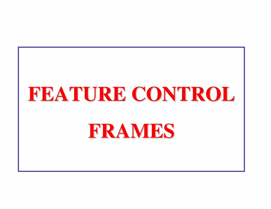
Example Datum's
• Datum's must be perpendicular to each other
–Primary
–Secondary
–Tertiary Datum

FIRST DATUM ESTABLISHEDBY THREE POINTS (MIN)CONTACT WITH SIMULATEDDATUM A
Primary DatumPrimary Datum

PRIMARY DATUM PLANE:
•The primary datum feature must make contact
with the theoretically exact datum plane in a
minimum of three points not in a line.
•The required contact is to prevent the part from
“rocking” during manufacturing or inspection
processes.

Primary Datum Plane

PRIMARY DATUM PLANE:
•This three-point contact is not difficult to achieve;
•If the designer has any concern about surface
irregularity, a surface control may be specified

SECOND DATUMPLANE ESTABLISHED BYTWO POINTS (MIN) CONTACTWITH SIMULATED DATUM B
Secondary DatumSecondary Datum

SECONDARY DATUM PLANE:
•Must be at a 90deg angle to the primary datum
plane.
•Usually selected as the second most functionally
important feature.
•This feature must be perpendicular to the primary
datum feature.
•There is only a two-point minimum contact
required for this plane.

SECONDARY DATUM PLANE:
•These two points establish the part in the other
direction to prevent it from rocking about the
primary datum plane.
•This plane may be a stop, fence, or angle plate
on processing or inspection equipment.

Tertiary DatumTertiary Datum
90°
THIRD DATUMPLANE ESTABLISHEDBY ONE POINT (MIN)CONTACT WITHSIMULATED DATUM C
MEASURING DIRECTIONS FOR RELATED DIMENSIONS

TERTIARY DATUM PLANE:
•Exactly at 90 deg angle to primary & secondary
planes
•The part must contact this plane at least at one
point.
•This contact is required for dimension origin and
to prevent any back-and-forth movement in the
third plane.

TERTIARY DATUM PLANE:
•The tertiary plane could be a locating or stop-pin
in a processing or inspection process.
•All measurements, setups, and inspections are to
be made from these three mutually perpendicular
planes.
Figure 3-7 is an illustration of the theoretical
datum reference frame.

ALL 3 DATUM PLANES
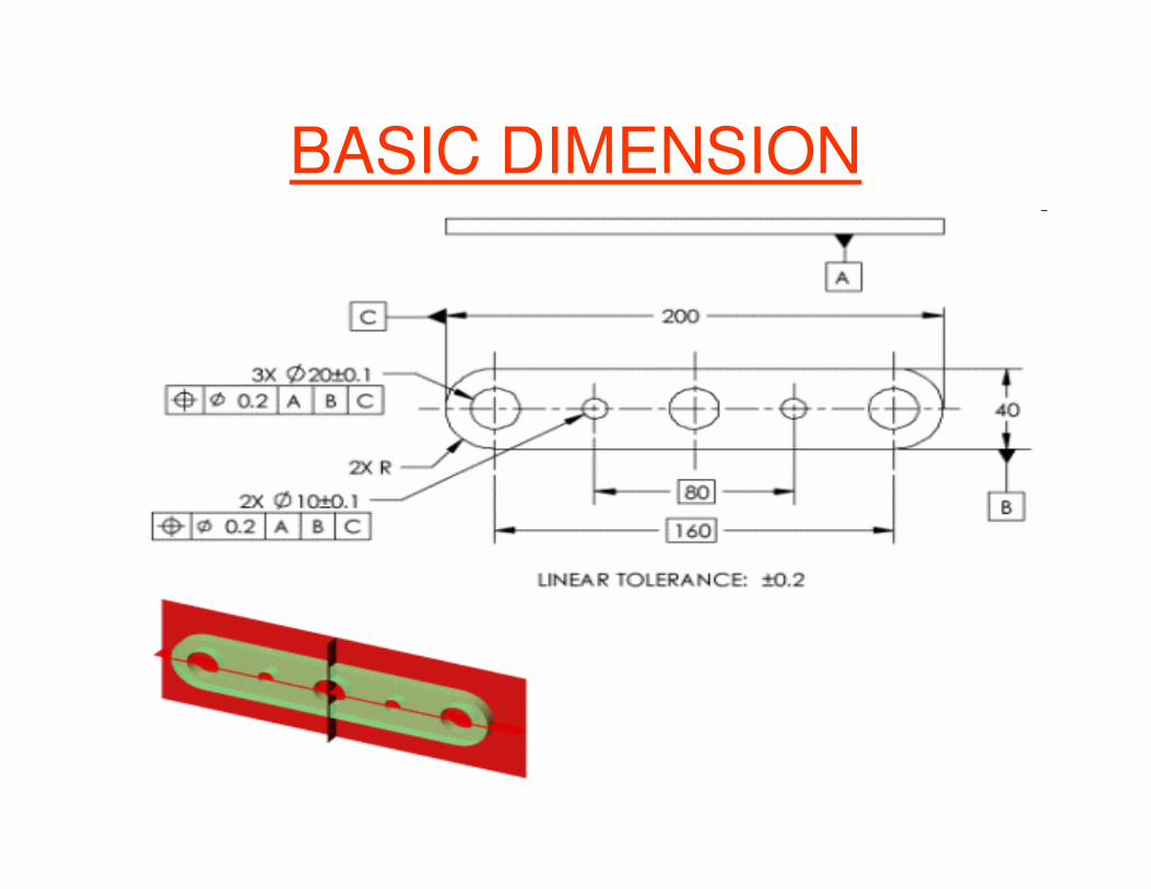
BASIC DIMENSION


INDIVIDUAL (No Datum
Reference)
INDIVIDUAL or RELATED
FEATURES
RELATED FEATURES
(Datum Reference Required)
GEOMETRIC CHARACTERISTIC CONTROLS
TYPE OFFEATURE
TYPE OFTOLERANCE CHARACTERISTIC SYMBOL
SYMMETRY
FLATNESS
STRAIGHTNESS
CIRCULARITY
CYLINDRICITY
LINE PROFILE
SURFACE PROFILE
PERPENDICULARITY
ANGULARITY
PARALLELISM
CIRCULAR RUNOUT
TOTAL RUNOUT
CONCENTRICITY
POSITION
FORM
PROFILE
ORIENTATION
RUNOUT
LOCATION
14 characteristics that may be controlled


Examples for symbols
Flatness as stated on drawing: The flatness of the feature must be within .06 tolerance zone.

Straightness
SYMBOL
Figure 6-1
DEFINITION
Straightness is the condition where one line
element of a surface or axis is in a straight line.

.003
0.500 ±.005
.0030.500 ±.005
Straightness applied to a flat surface: The straightness of the feature must be within .003 tolerance zone.


DEFINITION OF CIRCULARITY:
Circularity is roundness. Circularity is a condition
of a cylindrical surface, other than a sphere, at any
cross-sectional measurement where all points of
the surface are perpendicular to and equal distance
from a common axis during one complete
revolution of the feature.
Circularity of a sphere is a condition where all
points of the surface intersected by any plane
passing through a common center are equal
distance from that center.


Cylindricity:
Condition of an entire feature surface during one
revolution in which all surface points are an
equal distance from a common axis.


LINE PROFILE
Line profile tolerancing is a method of
specifying a two-dimensional control for a
single line element along the true profile of a
surface.
This control is usually specified for the shape
of cross-sections or cutting
planes of parts.

SURFACE PROFILE
Surface profile is a method of specifying a three-
dimensional control along the entire surface to be
controlled.
This control is usually applied to parts having
constant cross-section, surfaces of revolution,
weldments, forgings, etc., where an "all over"
requirement may be desired.
Surface control may apply all around.


Perpendicularity:
Condition of an entire surface, plane, or
axis at a right angle to a datum plane or
axis.

PERPENDICULARITY:
The tolerance zone is the space between the 2 parallel lines. They are perpendicular to the datum plane and spaced .005 apart.
The perpendicularity of this surface must be within a .005 tolerance zone relative to datum A.

perpendicularity


Angularity is the condition of an axis or plane
other than 90deg to another datum plane or axis.

Angularity

Angularity Orientation
Poor G D & T condition

Angularity Orientation
Good G D & T condition


parallelism
±0.01

Parallelism is the condition of a
surface, center plane or axis that is an
equal distance at all points from a
datum plane or axis.


RUNOUT:
•A composite form & location control of
permissible error in the desired part
surface during a complete revolution of the
part around a datum axis.


Concentricity:
Symbol:
Definition: Condition where the median points
of all diametrically opposed elements of a figure
of revolution (or correspondingly located
elements of two or more radially disposed
features) are congruent with the axis (or center
point) of a datum feature


Concentricity vs Runout

RUNOUT VS CONCENTRICITY
• Runout is inspected with a single indicator
while concentricity is inspected with two indicators placed opposite to each other.
• Both concentricity & runout are on diameters.(Eccentricity (no symbol) is on the radius).
• Runout considers form error while concentricity ignores form error.
• Runout is easier to inspect as compared to concentricity.
WHEN IN DOUBT – USE RUNOUT

SYMBOL FOR SYMMETRY
Symmetry:Condition where a feature or part
has the same profile on either side of the
central
(median plane) of a datum feature.


Position:
Position is the condition where a feature or group of features is located (positioned) in relation to another feature or datum feature

Positioning

EXAMPLE OF G.D. & T. ADVANTAGEGREATER FLEXIBILTY IN MANUFACTURING

www.tec-ease.com
• Also available in Tool Design serverhttp://server/knowledge-base/gd&t/main.htm

THANK YOU

Do’s & Don’t s of Dimensioning
Never dimension hidden lines

Do’s & Don’t s of Dimensioning

Avoid Over-Dimensioning

Avoid Over-Dimensioning

Basic Dimensioning Style
Continue dimensioning
Baseline dimensioning
Ordinate dimensioning


![New Microsoft PowerPoint Presentation.ppt [Read …media.mycrowdwisdom.com.s3.amazonaws.com/aaop/Resources/...Microsoft PowerPoint - New Microsoft PowerPoint Presentation.ppt [Read-Only]](https://img.dokumen.tips/doc/110x75/5f798734ccfe2c3952073dc2/new-microsoft-powerpoint-read-mediamycrowdwisdomcoms3amazonawscomaaopresources.jpg)