Embed Size (px)
Citation preview
MICROFLEX Project: MEMS on New Emerging Smart Textiles/Flexibles
Dr Steve Beeby
ESD Research Group
Smart Fabrics 2011
5th April 2011
S Beeby, M J Tudor, R Torah, K Yang, Y Wei

Overview
• Introduce the MicroFlex project
• What are MEMS?
– How are they made
– MicroFlex developments
• Case Study: Printed strain gauge on fabric
• Case Study 2: Printed piezoelectrics on fabrics
2
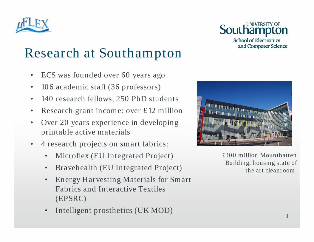
Research at Southampton
3
• ECS was founded over 60 years ago
• 106 academic staff (36 professors)
• 140 research fellows, 250 PhD students
• Research grant income: over £12 million
• Over 20 years experience in developing printable active materials
• 4 research projects on smart fabrics:
• Microflex (EU Integrated Project)
• Bravehealth (EU Integrated Project)
• Energy Harvesting Materials for Smart Fabrics and Interactive Textiles (EPSRC)
• Intelligent prosthetics (UK MOD)
£100 million Mountbatten Building, housing state of
the art cleanroom.
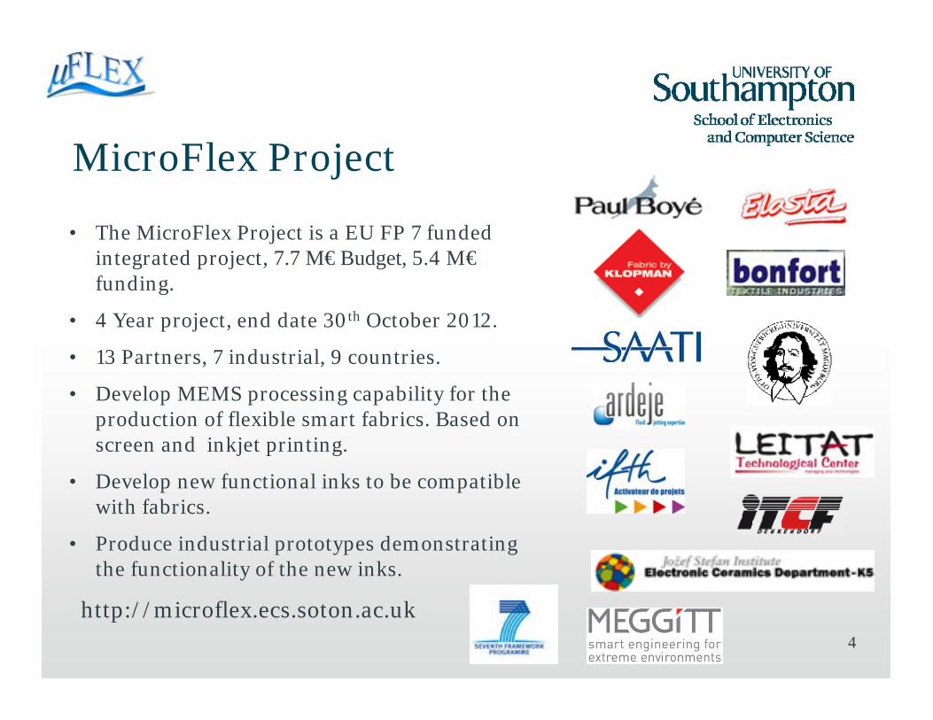
MicroFlex Project
4
• The MicroFlex Project is a EU FP 7 funded integrated project, 7.7 M€ Budget, 5.4 M€funding.
• 4 Year project, end date 30th October 2012.
• 13 Partners, 7 industrial, 9 countries.
• Develop MEMS processing capability for the production of flexible smart fabrics. Based on screen and inkjet printing.
• Develop new functional inks to be compatible with fabrics.
• Produce industrial prototypes demonstrating the functionality of the new inks.
http://microflex.ecs.soton.ac.uk
55
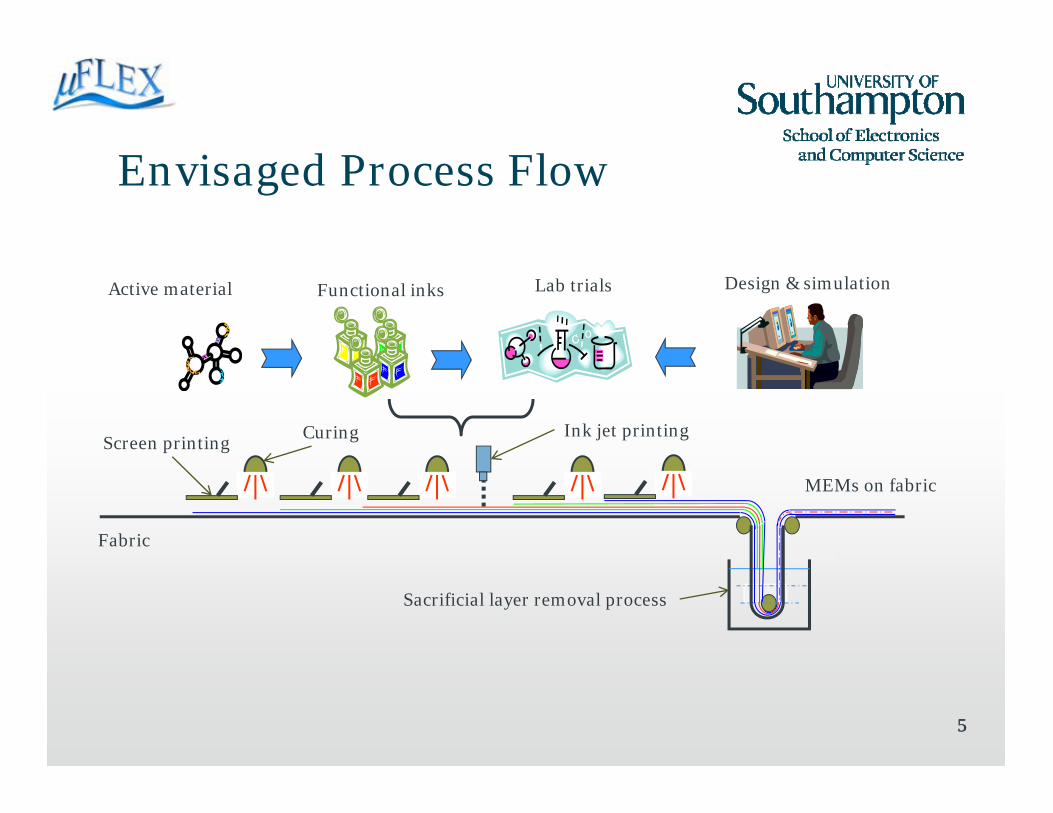
Envisaged Process Flow
Screen printingCuring Ink jet printing
MEMs on fabric
Fabric
Functional inks Lab trials Design & simulationActive material
Sacrificial layer removal process

6
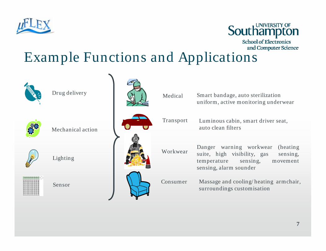
Example Functions and Applications
6
Mechanical action
Lighting
Sensor
Drug delivery Medical
Transport
Workwear
Consumer
Smart bandage, auto sterilization uniform, active monitoring underwear
Luminous cabin, smart driver seat, auto clean filters
Danger warning workwear (heatingsuite, high visibility, gas sensing,temperature sensing, movementsensing, alarm sounder
Massage and cooling/heating armchair, surroundings customisation
7
Example Functions and Applications
7
Mechanical action
Lighting
Sensor
Drug delivery Medical
Transport
Workwear
Consumer
Smart bandage, auto sterilization uniform, active monitoring underwear
Luminous cabin, smart driver seat, auto clean filters
Danger warning workwear (heatingsuite, high visibility, gas sensing,temperature sensing, movementsensing, alarm sounder
Massage and cooling/heating armchair, surroundings customisation
88
MEMS
• The MicroFlex project is concentrating on fabricating sensors and actuators (transducers).
• MEMS stands for MicroElectroMechanical Systems, i.e. they are systems that include mechanical and electrical functionality.
• Typical MEMS are miniature sensors and actuators.
• MEMS technology is dominated by Silicon microfabrication technology, although polymer materials / processes becoming increasingly used.

9
Example MEMS
x
y
Analogue devices ADXL 50 2 axis accelerometer, 3 mm2 surface area for integrated electronics and mechanical sensing element
Inertial mass displacements
sensed by interdigital
electrode array.
Mechanical element
10
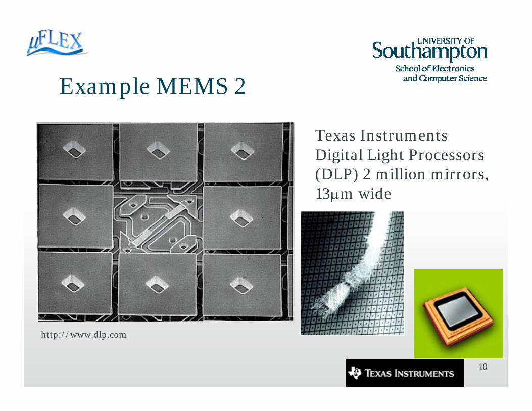
Example MEMS 2
Texas InstrumentsDigital Light Processors (DLP) 2 million mirrors, 13μm wide
http://www.dlp.com
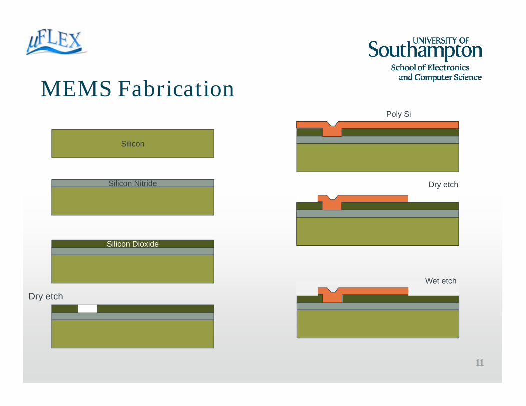
MEMS Fabrication
11
Silicon
Silicon Nitride
Silicon Dioxide
Dry etch
Poly Si
Dry etch
Wet etch

12
MEMS Fabrication on Fabrics
• Fabrics present a very different substrate compared with a silicon wafer
– Rough, uneven surface with pilosity
– Flexible and elastic
– Suitable for low temperature processing
– Limited compatibility with solvents and chemicals
• MicroFlex aims to use standard printing techniques to deposit a range of custom inks in order to realise freestanding mechanical structures coupled with active films for sensing and actuating.
13
14
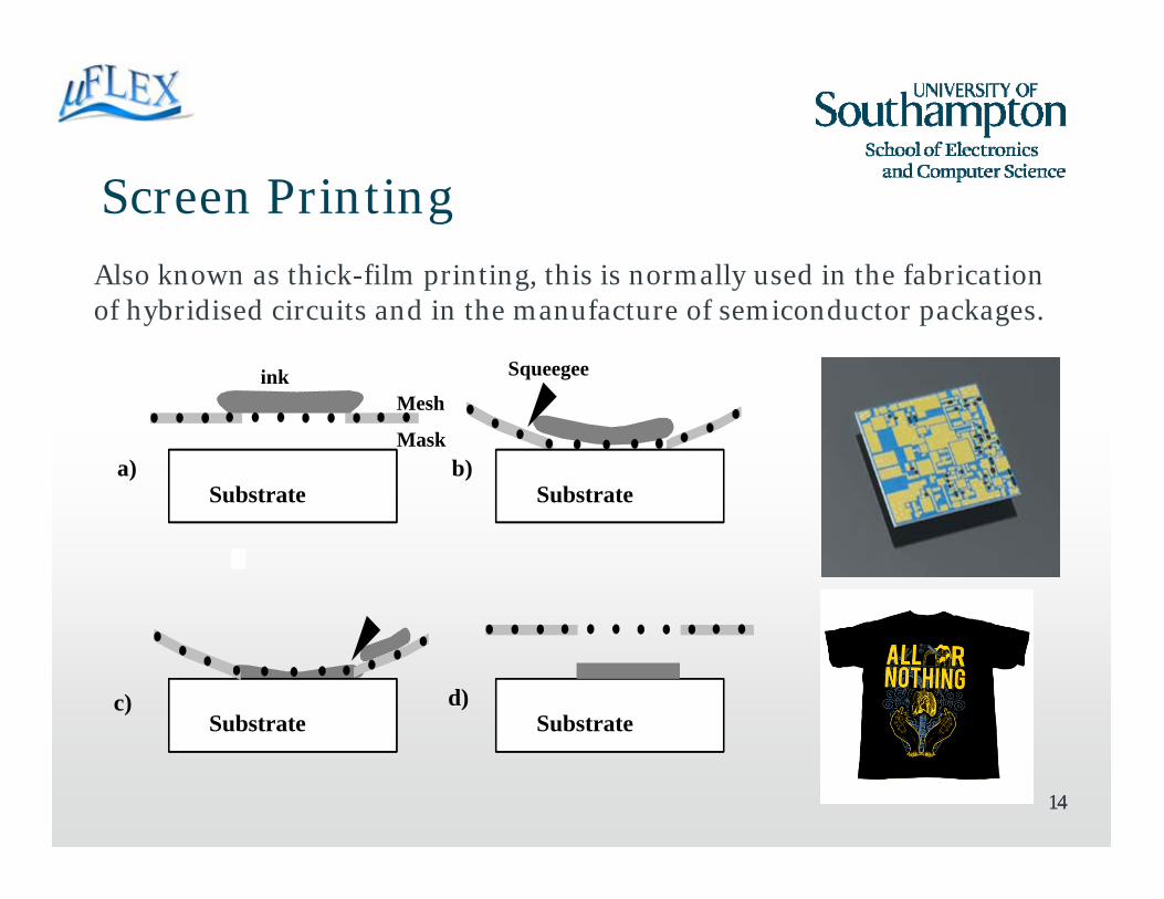
Screen Printing
14
Substrate Substrate
Substrate Substrate
Mesh
Mask
Squeegee
a) b)
c) d)
ink
Also known as thick-film printing, this is normally used in the fabrication of hybridised circuits and in the manufacture of semiconductor packages.
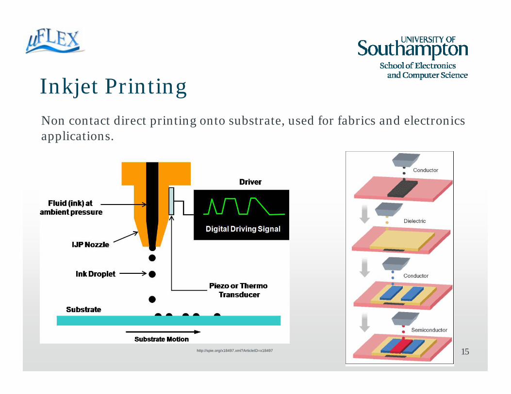
Inkjet Printing
15
Non contact direct printing onto substrate, used for fabrics and electronics applications.
http://spie.org/x18497.xml?ArticleID=x18497
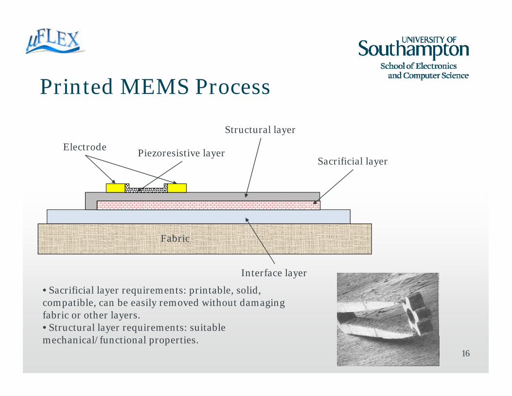
Printed MEMS Process
16
Piezoresistive layer
Interface layer
Sacrificial layer
Structural layer
Fabric
Electrode
• Sacrificial layer requirements: printable, solid, compatible, can be easily removed without damaging fabric or other layers.• Structural layer requirements: suitable mechanical/functional properties.
Case Study: Strain Gauge
• The MicroFlex project is structured so as to initially demonstrate the functional inks, and then use these in the sacrificial layer process.
• Printed strain gauge demonstrated by project partners Jožef Stefan Institute, ink developed by ITCF and fabric from Saati.
• Exploits the piezoresistive effect: the resistance of a printed film changes as it is strained (stretched) due to a change in the resistivity of the material.
• Useful for sensing movement, forces and strains.17
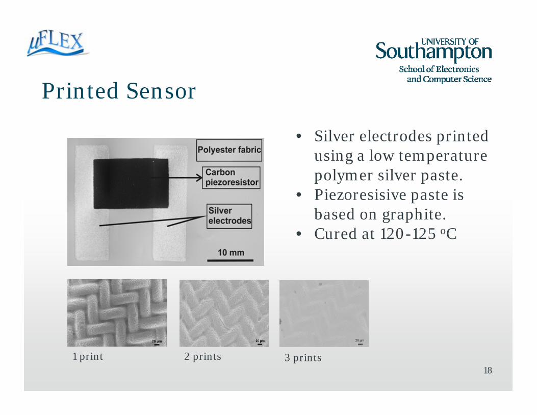
Printed Sensor
18
• Silver electrodes printed using a low temperature polymer silver paste.
• Piezoresisive paste is based on graphite.
• Cured at 120-125 oC
1 print 2 prints 3 prints

Results
• Sensitivity illustrated by the Gauge factor:
• Clear increase in resistance demonstrated as the fabric is strained.
• Conventional metal foil GF = 2
19
N° of graphite layer
R0 (Ω) at 0 % strain
R(Ω) at 1.5 % strain
Gauge factor
1 1905 2064 5.62 1100 1198 5.93 328 358 6.1
εRR
GFΔ
=
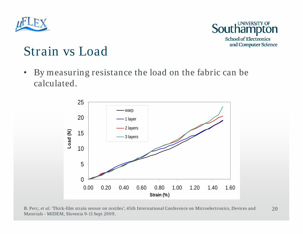
Strain vs Load
• By measuring resistance the load on the fabric can be calculated.
20
0
5
10
15
20
25
0.00 0.20 0.40 0.60 0.80 1.00 1.20 1.40 1.60Strain (%)
Load
(N)
warp
1 layer
2 layers
3 layers
B. Perc, et al. ‘Thick-film strain sensor on textiles’, 45th International Conference on Microelectronics, Devices and Materials - MIDEM, Slovenia 9-11 Sept 2009.
21
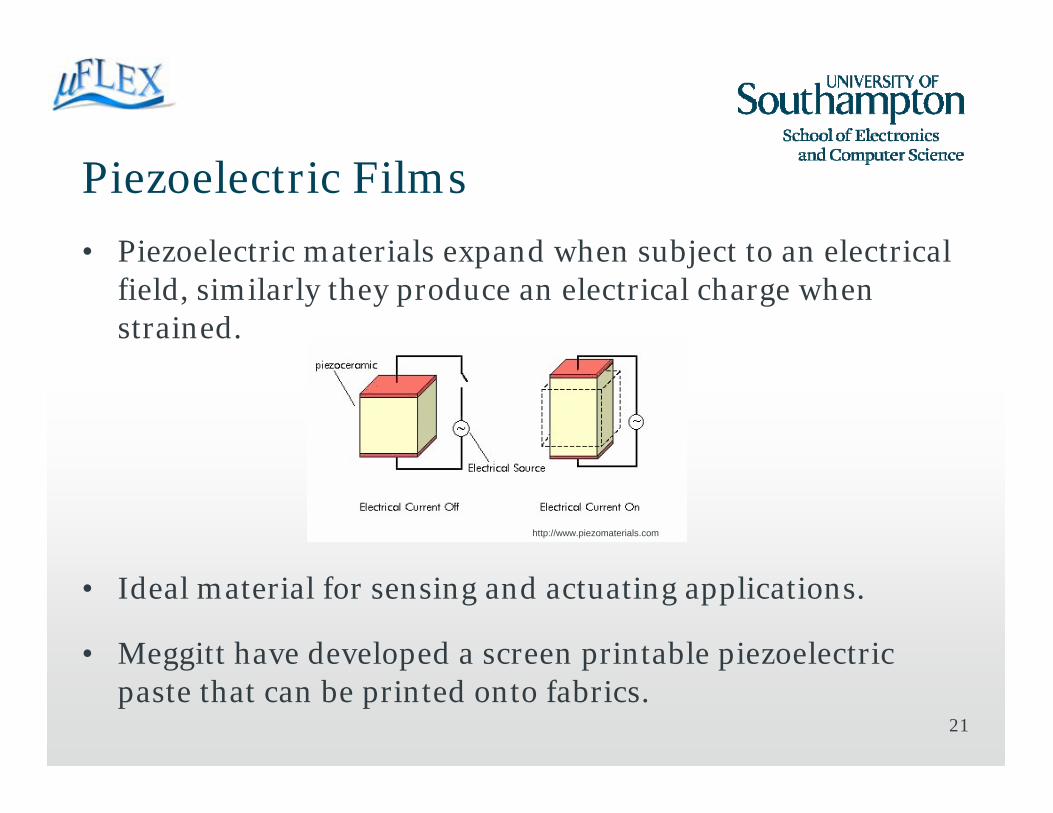
Piezoelectric Films
• Piezoelectric materials expand when subject to an electrical field, similarly they produce an electrical charge when strained.
• Ideal material for sensing and actuating applications.
• Meggitt have developed a screen printable piezoelectric paste that can be printed onto fabrics.
http://www.piezomaterials.com
22
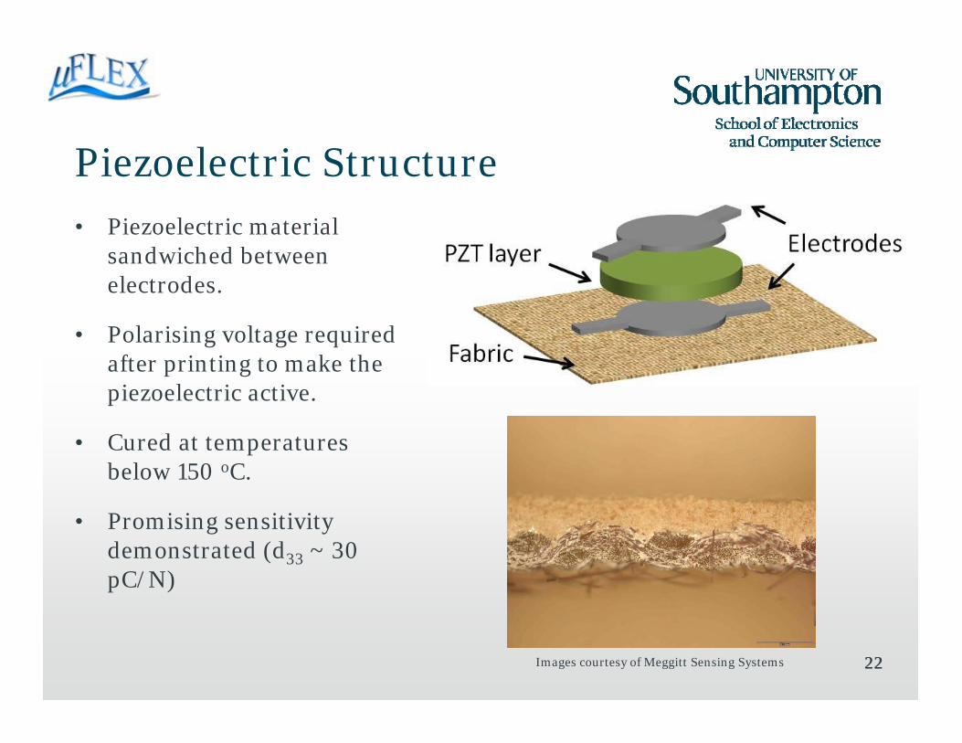
Piezoelectric Structure • Piezoelectric material
sandwiched between electrodes.
• Polarising voltage required after printing to make the piezoelectric active.
• Cured at temperatures below 150 oC.
• Promising sensitivity demonstrated (d33 ~ 30 pC/N)
22Images courtesy of Meggitt Sensing Systems
Other Examples
23
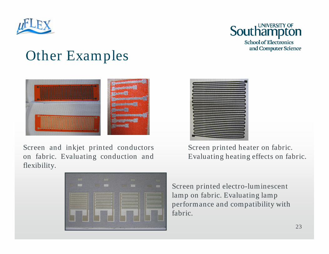
Screen and inkjet printed conductorson fabric. Evaluating conduction andflexibility.
Screen printed heater on fabric. Evaluating heating effects on fabric.
Screen printed electro-luminescent lamp on fabric. Evaluating lamp performance and compatibility with fabric.

Conclusions
• MEMS technology is widely established in a multitude of applications.
• MicroFlex will develop the materials and processes required to fabricate MEMS on fabrics.
• Range of active inks has already been demonstrated.
• Currently preparing phase one prototypes based upon these active inks.
• Sacrificial layer fabrication process has also been demonstrated and will be combined with active inks in phase two prototypes.
24

Acknowledgements
25
Colleagues at Southampton, MicroFlex partners and EU for funding (CP-IP 211335-2).
Thanks for your attention!