Embed Size (px)
Citation preview
Microcontroller Application for Linear
and Rotational Motion Sensing
Computer Engineering Senior Project
California Polytechnic State University, San Luis Obispo
Author: Zachary Mintzer
Advisor: John Seng
Fall 2015

1
Table of Contents Introduction .................................................................................................................................................. 2
Problem Statement ....................................................................................................................................... 2
Theory behind the Accelerometer and Gyroscope ....................................................................................... 3
Accelerometer........................................................................................................................................... 3
Gyroscope ................................................................................................................................................. 4
Hardware ...................................................................................................................................................... 5
STM32 Nucleo F411RE Microcontroller .................................................................................................... 7
Triple-Axis MMA8451Q Accelerometer .................................................................................................... 7
Triple-Axis L3GD20H Gyroscope ............................................................................................................... 8
2.8” ILI9341 TFT LCD Shield ....................................................................................................................... 8
Software ........................................................................................................................................................ 9
Software Main Program Flow ................................................................................................................... 9
Software Architecture ............................................................................................................................. 11
Class: My_I2C .......................................................................................................................................... 13
Class: MMA8451Q................................................................................................................................... 15
Class: L3GD20H ....................................................................................................................................... 16
Mechanical .................................................................................................................................................. 18
Budget and Bill of Materials ........................................................................................................................ 19
Lessons Learned .......................................................................................................................................... 20
Conclusion ................................................................................................................................................... 21
Appendix A: References .............................................................................................................................. 23
Appendix B: Code ........................................................................................................................................ 24
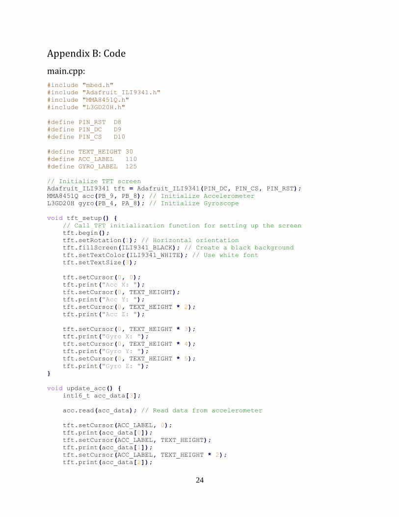
main.cpp: ................................................................................................................................................ 24
My_I2C.h: ................................................................................................................................................ 26
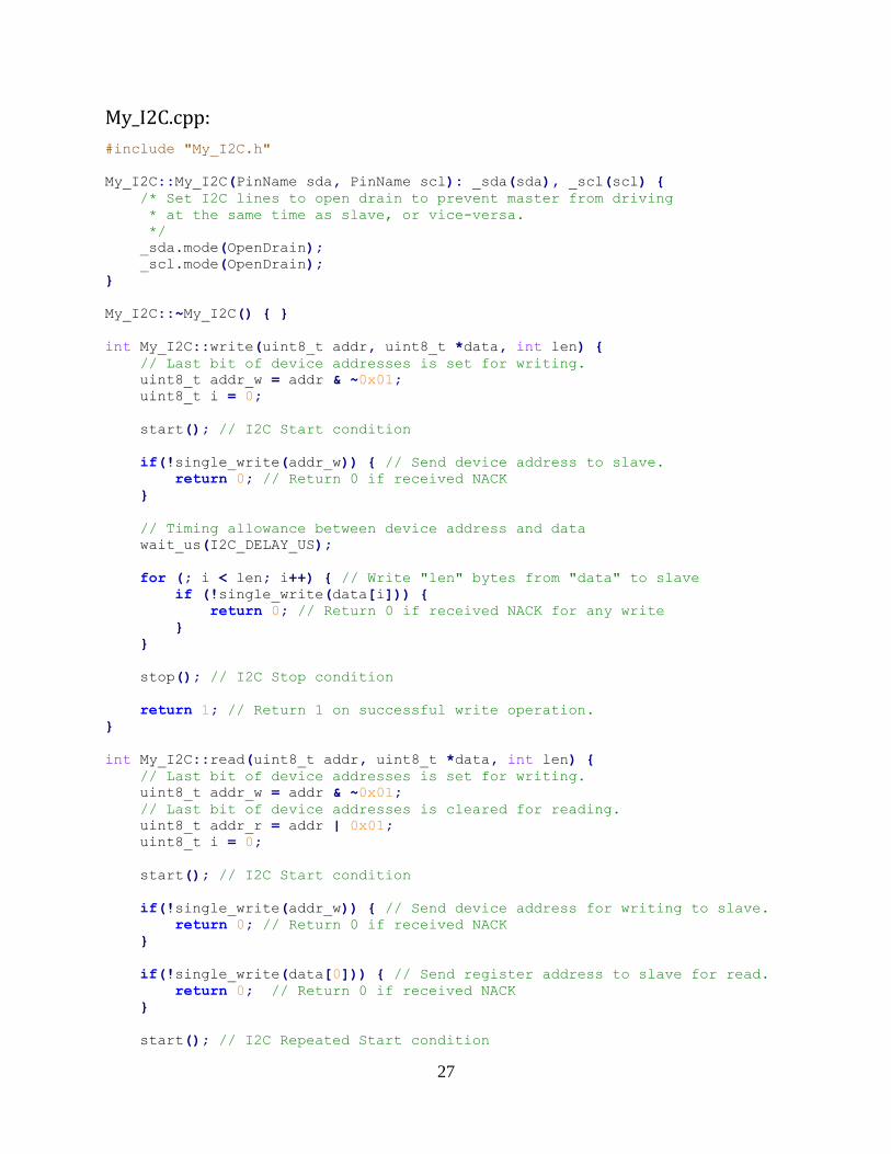
My_I2C.cpp: ............................................................................................................................................ 27
MMA8451Q.h: ........................................................................................................................................ 31
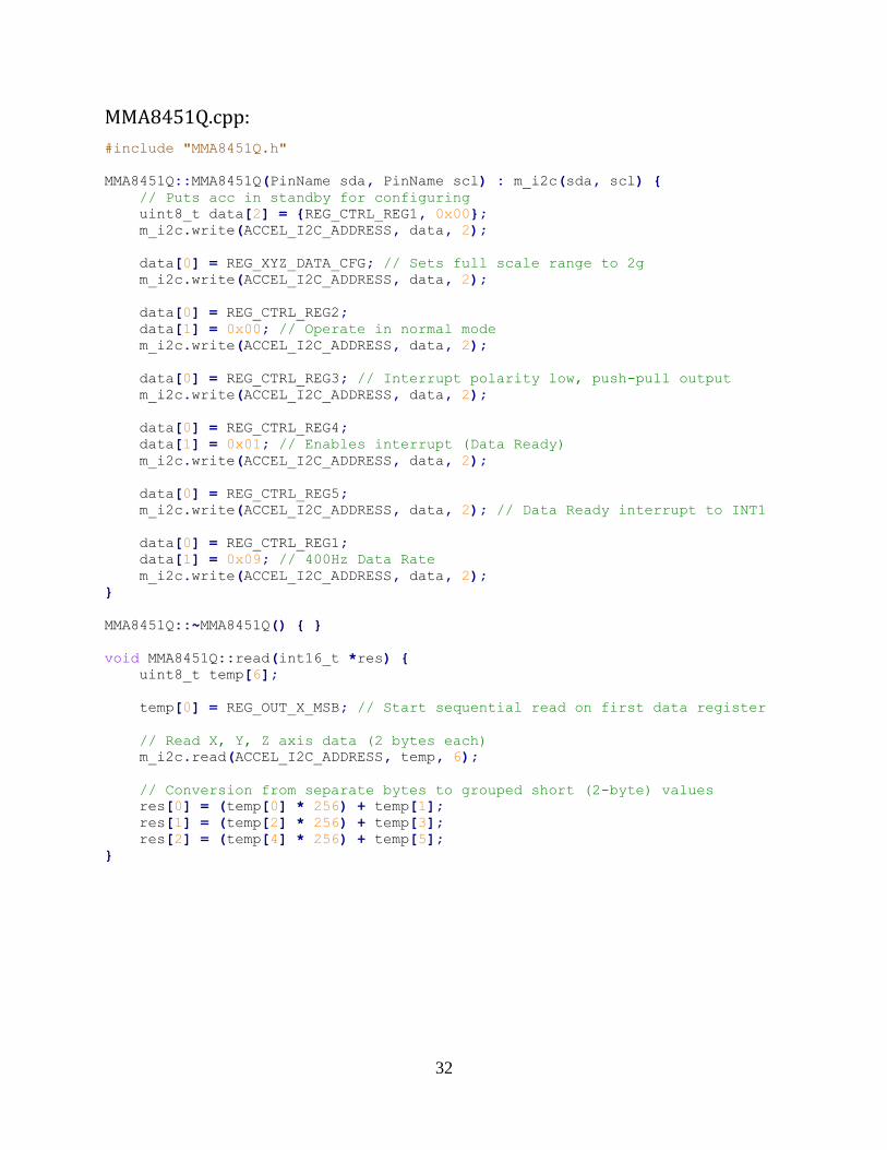
MMA8451Q.cpp: ..................................................................................................................................... 32
L3GD20H.h: ............................................................................................................................................. 33
L3GD20H.cpp: ......................................................................................................................................... 34
2
Introduction
Motion capture can be best described as being able to analyze and use the measured
movement experienced by or forced upon objects, as well as the orientation and position of
those objects. Many devices and technologies have been using motion analysis for quite some
time, however as technology continues to advance faster we are seeing motion capture being
featured in common consumer devices as well. The most common example of a well-known
device which utilizes accelerometer and gyroscope sensors to capture motion is the
smartphone. There are plenty of applications used on smartphones which utilize motion
capture, such as changing the screen orientation for the user, using the device’s motion to play
interactive games, and being able to utilize the accelerometer and gyroscope together as a
compass [1]. Other common applications for accelerometers and gyroscopes are determining
aircraft orientation for pilot controls, interpreting human gestures in software to act similarly to
how we tend to use a computer mouse (such as the Nintendo Wii using a motion controller),
and camera stabilization to optimize image capturing by offsetting the camera’s detected
movement [2]. Overall, there are many modern day applications that use motion capture
already, and as technological innovation continues it is likely that we will continue to see
motion capture being utilized.
Problem Statement
The primary goal of this project is to accurately record the orientation and motion experienced
by the collective components which make up the final device. This is achieved by interfacing an
accelerometer sensor to determine the orientation and non-gravitational linear acceleration of
the device; a gyroscope sensor is used to measure the gravitational pull on the device,
capturing its rotational acceleration. Each of these sensors communicates with a
microcontroller using separate I2C master/slave wirings. The microcontroller then displays the
collected motion data from the accelerometer and gyroscope on a small LCD screen by
communicating over SPI. The final project results in an embedded system which reads motion
data from two sensors in real-time, and shows this data on an LCD display.
3
Theory behind the Accelerometer and Gyroscope
Accelerometer
The general purpose of an accelerometer is to measure the linear acceleration experienced by
the given measured device. Linear acceleration can be described by the change in velocity of an
object over a period of time, or by using Newton’s second law of motion such that acceleration
is the amount of force required to move a given mass [3]. As a result, accelerometers typically
collect their data by detecting how much force is being applied to the device in the direction of
each of the sensor’s axes. The type of accelerometer being utilized in this project is a smaller
scale chip, which uses a primary electrode inside a semiconductor container with additional
electrodes surrounding the primary one, and the changing distance between each of the
surrounding electrodes as the accelerometer changes its acceleration and orientation
determines the data being measured [4].
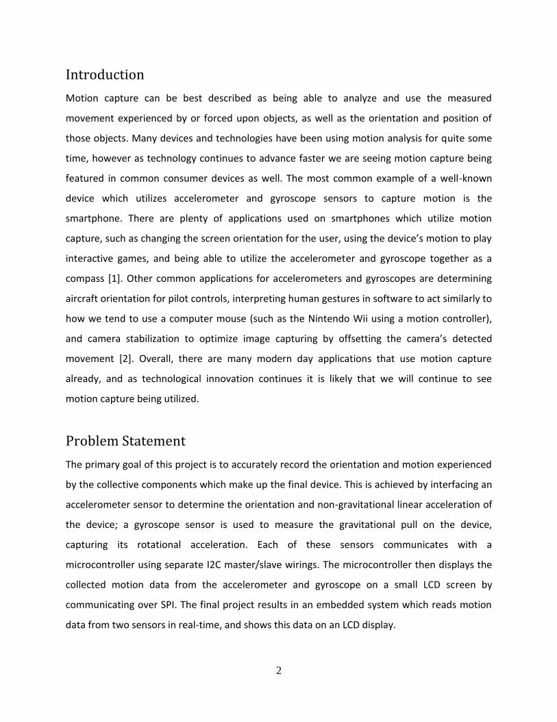
Figure 1: Operation of an accelerometer sensor at the MEMS level
Figure 1 depicts how an accelerometer sensor operates at the MEMS (Micro-machined Electro-
Mechanical Systems) level. The electrode plates on either side of the extended sections of the
movable mass detect the acceleration of the mass from the capacitance between the mass and
4
the plates. The mass is able to move because it is suspended by micro-mechanical springs. The
capacitance measures acceleration because the distance between the movable mass and the
electrode plates shares a physical relationship with the capacitance detected by the electrodes
as the mass accelerates from the motion caused by the springs (C = εA
𝑑).
Gyroscope
Gyroscopes are used to measure the rotational velocity of an object, and the ones used for
most embedded system sensors utilize a vibrating structure gyroscope rather than the
traditional rotary gyroscope that most people are familiar with. Vibrating structure gyroscopes
are MEMS devices that utilize the Coriolis force. The Coriolis force represents the force of an
object whose relative angular position is maintained while the object experiences a lateral
speed causing angular velocity. Vibrating structure gyroscopes contain small masses which are
fixed to set array of springs that can then resonate in a capacitive outer shell structure as an
object rotates, and the Coriolis force is then detected by the outer shell [5]. This
implementation of a gyroscope allows for creating miniaturized sensors that are still able to
experience and record the rotational motion experienced by devices.
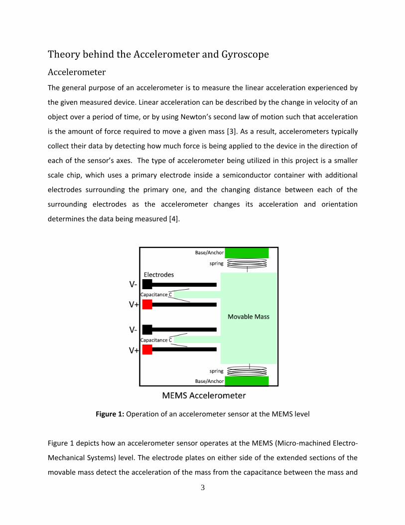
Below, Figure 2 depicts the MEMS structure of a gyroscope with the spring array structure
described. The encapsulating structure contains a block that can make rotational movement in
the open space permitted. This block is composed of an array of springs that allow the
centerpiece mass to move in various directions. The movement of the mass is sensed by the
capacitive sensors surrounding the spring array in order to detect the relative rotational
movement as felt due to the Coriolis force previously discussed. The Coriolis force is measured
from the differences in capacitance measured by the capacitive plates; as the mass is pushed by
the Coriolis force in different directions while the structure rotates, the capacitance measured
by the sensors changes and reads the angular velocity as a result.

5
Figure 2: Diagram of MEMS gyroscope using Coriolis force
Hardware
The central driving component of the device is the STM32 Nucleo F411RE microcontroller, an
easily-adaptable development board that offers many available GPIO’s for communicating with
multiple peripherals. The accelerometer sensor used is the Adafruit Triple-Axis MMA8451Q
Accelerometer, and the gyroscope sensor used is the Adafruit Triple-Axis L3GD20H Gyro. In
order to display the data from the sensors, the 2.8” ILI9341 TFT LCD shield is used; although this
shield is typically used for Arduino microcontrollers, the Nucleo F411RE supports Arduino
6
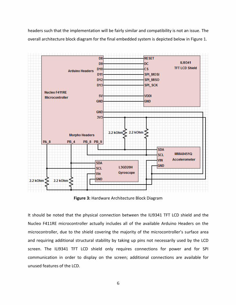
headers such that the implementation will be fairly similar and compatibility is not an issue. The
overall architecture block diagram for the final embedded system is depicted below in Figure 1.
Figure 3: Hardware Architecture Block Diagram
It should be noted that the physical connection between the ILI9341 TFT LCD shield and the
Nucleo F411RE microcontroller actually includes all of the available Arduino Headers on the
microcontroller, due to the shield covering the majority of the microcontroller’s surface area
and requiring additional structural stability by taking up pins not necessarily used by the LCD
screen. The ILI9341 TFT LCD shield only requires connections for power and for SPI
communication in order to display on the screen; additional connections are available for
unused features of the LCD.

7
STM32 Nucleo F411RE Microcontroller
The Nucleo F411RE microcontroller features a 32-bit ARM Cortex-M4 CPU running at 100MHz,
512 KB Flash and 128 KB SRAM, and over 50 GPIO to be utilized for communicating with
peripherals. Its layout of GPIO is meant to mimic the design of a typical Arduino layout, thereby
supporting Arduino-compatible peripherals and features, and providing familiarity to people
who have worked with Arduinos before. The board also supplies GPIO labeled as Morpho
Headers, in addition to the Arduino Headers, in order to give users the maximum amount of
possibilities for designing projects. However through extensive use and testing of the
microcontroller several drawbacks have been found, such as being unable to utilize multiple of
the available features of the board simultaneously or receiving consistent behavior after
flashing a program. Programs which don’t rely too heavily on simultaneous timing between
multiple peripherals, or that avoid an event-driven approach, are encouraged in order to avoid
these potential issues.
Triple-Axis MMA8451Q Accelerometer
The MMA8451Q accelerometer sensor includes a 14-bit ADC for high-precision linear motion
and orientation readings. It communicates using standard I2C protocol, therefore requiring only
four wires total (two for power, two for I2C). The sensor only requires a 3.3V voltage supply due
to an included voltage regulator circuit on the breakout for the sensor, but the MMA8451Q
chip itself only requires a 3V input. I2C protocol uses a data line (SDA) and a clock line (SCL)
between two devices typically in a master/slave configuration. Pull-up resistors are required on
both the SDA and SCL lines due to the active-low circuitry typically used for I2C devices, such
that the master and slave devices either drive their lines low, or leave them high. The pull-up
resistors are used in order to quickly bring the signal of the circuit back high. The accelerometer
will communicate with the Nucleo F411RE microcontroller in order to provide it with data
describing the current linear acceleration and orientation of the device in the X, Y, and Z axes.

8
Triple-Axis L3GD20H Gyroscope
The L3GD20H gyroscope sensor reads rotational motion at as accurate as ±250 degrees-per-
second and provides 16 bits of data output for each axis. Like the accelerometer, the gyroscope
also uses I2C as its interface, therefore only requiring four wires and the use of pull-up resistors
on the SDA and SCL lines. The L3GD20H chip has a 3.3V maximum voltage input, however the
full breakout circuit includes a voltage regulator to allow for 5V voltage supplies as well in order
to expand compatibility. The gyroscope interfaces the Nucleo F411RE microcontroller to
transmit the current rate of rotation of the system in all three directions.
2.8” ILI9341 TFT LCD Shield
This TFT (thin-film transistor) LCD shield is designed primarily for Arduino microcontrollers,
given its intended design for fitting into the header layout for most Arduino boards. However,
thankfully the Nucleo F411RE microcontroller includes an Arduino header layout. The screen is
2.8” diagonally and features a backlight, 18-bit color, and a 320x240 pixel resolution. The
primary chip handling screen operations is the ILI9341, which transmits data with the
microcontroller using SPI. SPI is a synchronous communication protocol that utilizes separate
clock and data lines to maximize speed efficiency at the cost of more wires. Most SPI devices
include a select line to allow for communicating with multiple devices. Although SPI is a fairly
fast protocol, the relatively high resolution and large color range actually create some
limitations for utilizing this type of screen in other applications, such as real-time full screen
animation. Without additional buffering that the screen’s onboard RAM doesn’t already
support, it is very difficult to update many pixels per second on the screen without creating a
flickering effect. Since the application of the screen for this project is simply to display the data
collected from the other motion-capturing sensors, the screen will meet the necessary
requirements. Due to the extensive GPIO provided on the Nucleo F411RE microcontroller, the
fact that the TFT LCD occupies the set of Arduino headers is not a problem; there are enough
alternative GPIOs available for the scope of the project. The Nucleo F411RE will use the screen
to display the real-time data from the MMA8451Q accelerometer and L3GD20H gyroscope
sensors, showing the X, Y, and Z axis motion and orientation data in plain, easily readable text.

9
Software
All software for the Nucleo F411RE microcontroller is written and compiled on mbed’s Online
Compiler IDE, which provides a workspace for organizing and writing code, then compiling
programs and flashing them to a USB-connected microcontroller. The mbed API provides a
wealthy resource of available functions and libraries to use for projects. In addition, APIs for the
ILI9341 TFT LCD are provided from the mbed library collection in order to provide
straightforward functionality for utilizing the screen to simply display data from the sensors.
Although the mbed API includes a kernel level I2C library and provides additional libraries for
interfacing the MMA8451Q accelerometer and L3GD20H gyroscope, all code for interfacing
with these sensors is written by me, including the I2C library being written at the user level. All
of the code is written in C++ with an object-oriented approach; classes are used to represent
each of the sensors, and utilize a custom I2C class I created in order to cleanly organize the
program’s architectural structure.
Software Main Program Flow
Figure 2 depicts the overall software flow of the main program running. As a real-time system,
the program does not end, and it continues to run until the device is disconnected from its
power source.
10
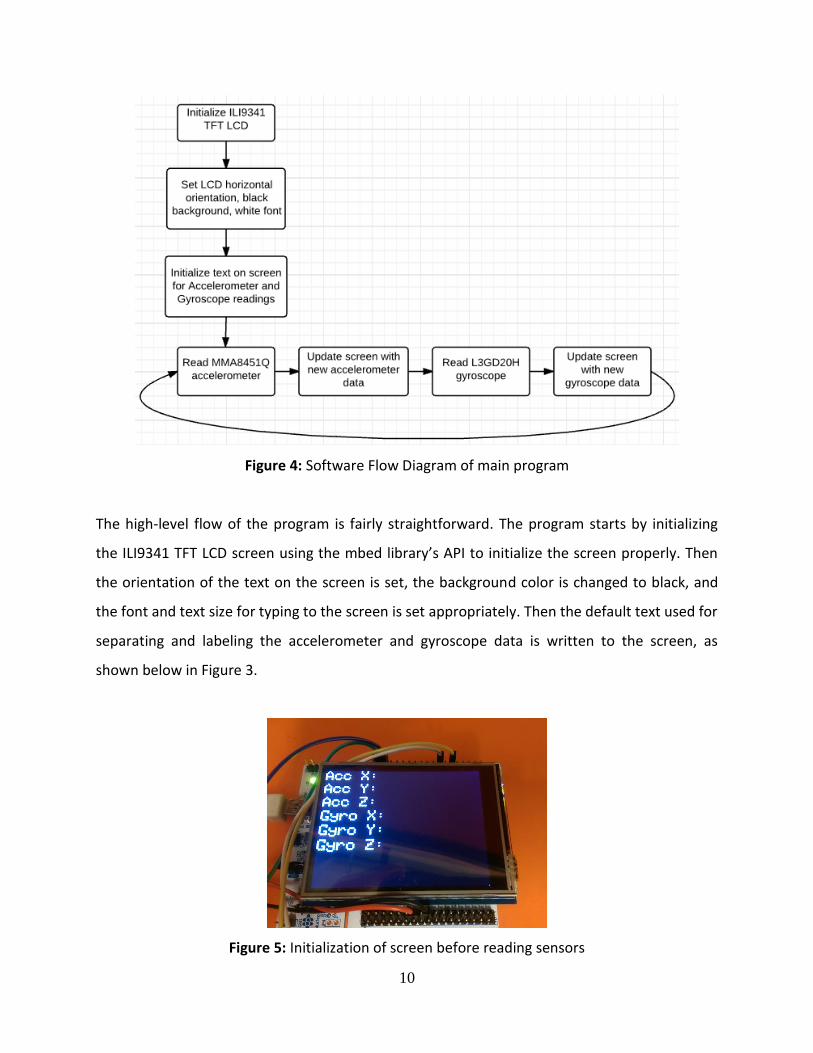
Figure 4: Software Flow Diagram of main program
The high-level flow of the program is fairly straightforward. The program starts by initializing
the ILI9341 TFT LCD screen using the mbed library’s API to initialize the screen properly. Then
the orientation of the text on the screen is set, the background color is changed to black, and
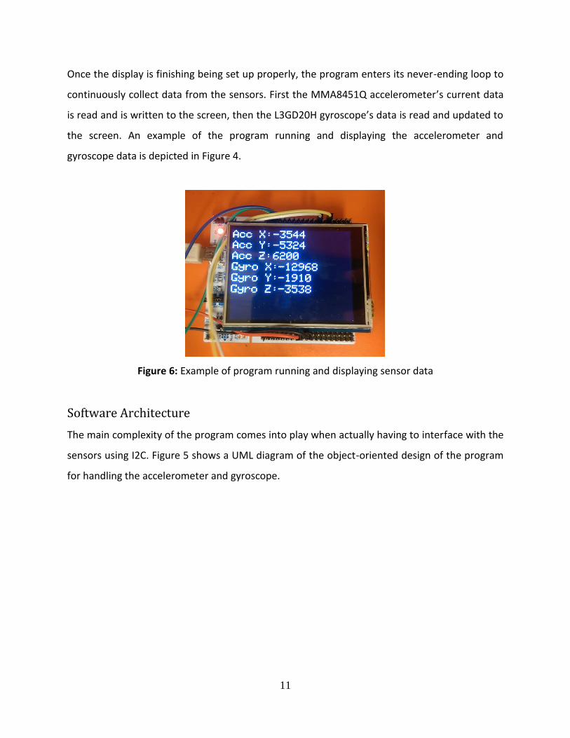
the font and text size for typing to the screen is set appropriately. Then the default text used for
separating and labeling the accelerometer and gyroscope data is written to the screen, as
shown below in Figure 3.
Figure 5: Initialization of screen before reading sensors
11
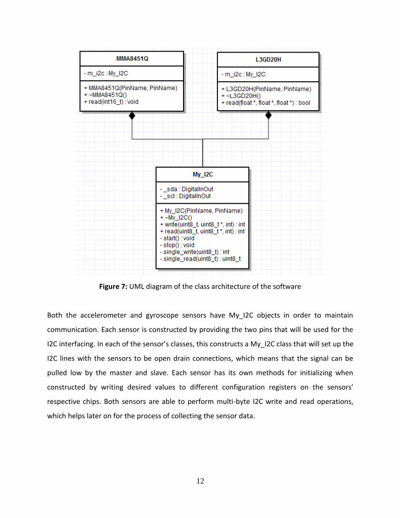
Once the display is finishing being set up properly, the program enters its never-ending loop to
continuously collect data from the sensors. First the MMA8451Q accelerometer’s current data
is read and is written to the screen, then the L3GD20H gyroscope’s data is read and updated to
the screen. An example of the program running and displaying the accelerometer and
gyroscope data is depicted in Figure 4.
Figure 6: Example of program running and displaying sensor data
Software Architecture
The main complexity of the program comes into play when actually having to interface with the
sensors using I2C. Figure 5 shows a UML diagram of the object-oriented design of the program
for handling the accelerometer and gyroscope.
12
Figure 7: UML diagram of the class architecture of the software
Both the accelerometer and gyroscope sensors have My_I2C objects in order to maintain
communication. Each sensor is constructed by providing the two pins that will be used for the
I2C interfacing. In each of the sensor’s classes, this constructs a My_I2C class that will set up the
I2C lines with the sensors to be open drain connections, which means that the signal can be
pulled low by the master and slave. Each sensor has its own methods for initializing when
constructed by writing desired values to different configuration registers on the sensors’
respective chips. Both sensors are able to perform multi-byte I2C write and read operations,
which helps later on for the process of collecting the sensor data.

13
Class: My_I2C
The I2C class I created implements the I2C protocol at the user level. This is primarily achieved
using careful timing sequences to match the expected behavior of the data (SDA) and clock
(SCL) lines. A typical I2C transmission begins with a start condition, and ends with a stop
condition. The behavior of these conditions is shown below in Figure 6.
Figure 8: I2C Start and Stop conditions [6].
Then the slave device’s address is transmitted on the SDA line synchronously with the provided
SCL line, and is followed by an acknowledgement (ACK) from the slave on SDA. It’s important to
note that the device address for the beginning of an I2C transmission has its least significant bit
set to 1 to indicate a write operation. If SDA is pulled low, that represents the slave sending an
ACK. If SDA is left high following a write to the device, then the slave is sending a non-
acknowledgement to the master (NACK). Figure 7 shows an example of sending the device
address to the MMA8451Q accelerometer sensor, followed by an ACK signaling to continue the
transmission.

14
Figure 9: I2C Master writing the device address to the slave, and receiving an ACK
The master then follows the same writing transmission procedure as with the device address,
but this time sends the desired register address that the master wishes to write data to on the
slave. This step will also be ACK’d or NACK’d by the slave. If the register address is
acknowledged by the slave then the I2C protocol can continue, however the remainder of the
transmission is different based on a read or write operation. For writing, the master proceeds
to write data to the device’s given register as long as the slave sends back ACKs for each write,
and the procedure is halted when the master decides to send the I2C stop condition. If reading
data from the slave’s register, instead the master will resend the I2C start condition and device
address with the least significant bit set to 0. Once the device address for reading is ACK’d by
the slave, the slave will continue to send data over the SDA line one byte at a time. For the read
operation, each byte must be acknowledged by the master over the SDA line until the master
wishes to stop reading consecutive registers from the device. Once the master is done reading
from the slave, it will send a NACK followed by the I2C stop condition.
15
All of these operations required for interfacing over I2C are contained in the My_I2C class. The
class constructor is provided with two pins from the Nucleo F411RE microcontroller to use for
the SDA and SCL signals, and sets them up as open drain. My_I2C provides public write and read
functions to communicate with slave devices, and manage the timings and protocol specifics of
I2C as necessary. This makes utilizing the My_I2C class with the accelerometer and gyroscope
sensors fairly easy, since the classes required for each of the sensors then only need to write
and read certain bytes to acquire the desired motion data properly.
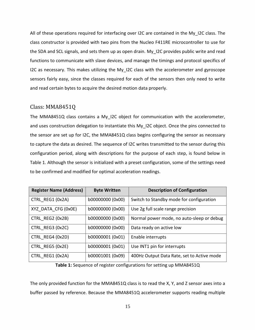
Class: MMA8451Q
The MMA8451Q class contains a My_I2C object for communication with the accelerometer,
and uses construction delegation to instantiate this My_I2C object. Once the pins connected to
the sensor are set up for I2C, the MMA8451Q class begins configuring the sensor as necessary
to capture the data as desired. The sequence of I2C writes transmitted to the sensor during this
configuration period, along with descriptions for the purpose of each step, is found below in
Table 1. Although the sensor is initialized with a preset configuration, some of the settings need
to be confirmed and modified for optimal acceleration readings.
Register Name (Address) Byte Written Description of Configuration
CTRL_REG1 (0x2A) b00000000 (0x00) Switch to Standby mode for configuration
XYZ_DATA_CFG (0x0E) b00000000 (0x00) Use 2g full scale range precision
CTRL_REG2 (0x2B) b00000000 (0x00) Normal power mode, no auto-sleep or debug
CTRL_REG3 (0x2C) b00000000 (0x00) Data ready on active low
CTRL_REG4 (0x2D) b00000001 (0x01) Enable interrupts
CTRL_REG5 (0x2E) b00000001 (0x01) Use INT1 pin for interrupts
CTRL_REG1 (0x2A) b00001001 (0x09) 400Hz Output Data Rate, set to Active mode
Table 1: Sequence of register configurations for setting up MMA8451Q
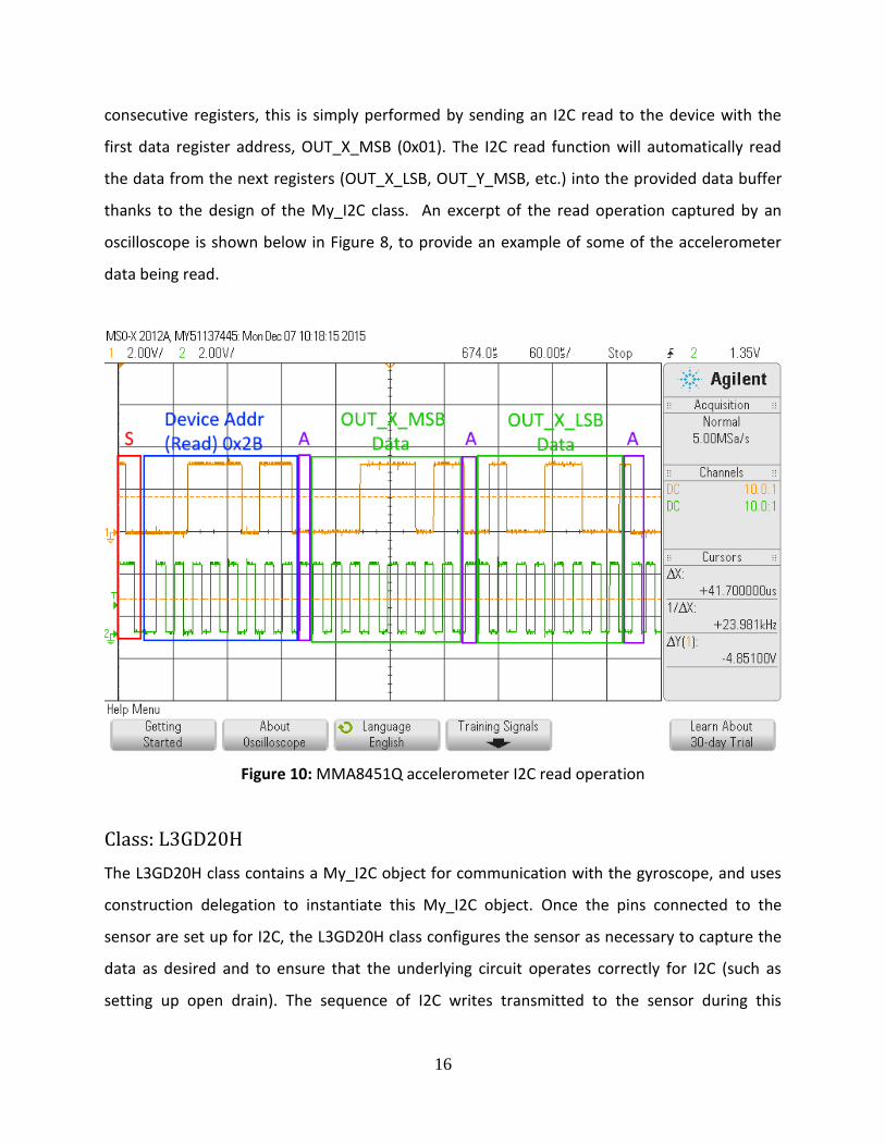
The only provided function for the MMA8451Q class is to read the X, Y, and Z sensor axes into a
buffer passed by reference. Because the MMA8451Q accelerometer supports reading multiple
16
consecutive registers, this is simply performed by sending an I2C read to the device with the
first data register address, OUT_X_MSB (0x01). The I2C read function will automatically read
the data from the next registers (OUT_X_LSB, OUT_Y_MSB, etc.) into the provided data buffer
thanks to the design of the My_I2C class. An excerpt of the read operation captured by an
oscilloscope is shown below in Figure 8, to provide an example of some of the accelerometer
data being read.
Figure 10: MMA8451Q accelerometer I2C read operation
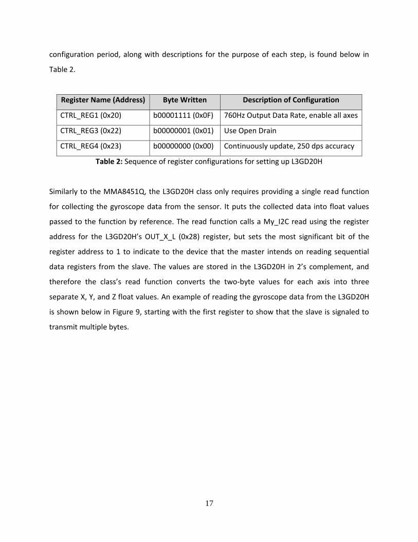
Class: L3GD20H
The L3GD20H class contains a My_I2C object for communication with the gyroscope, and uses
construction delegation to instantiate this My_I2C object. Once the pins connected to the
sensor are set up for I2C, the L3GD20H class configures the sensor as necessary to capture the
data as desired and to ensure that the underlying circuit operates correctly for I2C (such as
setting up open drain). The sequence of I2C writes transmitted to the sensor during this
17
configuration period, along with descriptions for the purpose of each step, is found below in
Table 2.
Register Name (Address) Byte Written Description of Configuration
CTRL_REG1 (0x20) b00001111 (0x0F) 760Hz Output Data Rate, enable all axes
CTRL_REG3 (0x22) b00000001 (0x01) Use Open Drain
CTRL_REG4 (0x23) b00000000 (0x00) Continuously update, 250 dps accuracy
Table 2: Sequence of register configurations for setting up L3GD20H
Similarly to the MMA8451Q, the L3GD20H class only requires providing a single read function
for collecting the gyroscope data from the sensor. It puts the collected data into float values
passed to the function by reference. The read function calls a My_I2C read using the register
address for the L3GD20H’s OUT_X_L (0x28) register, but sets the most significant bit of the
register address to 1 to indicate to the device that the master intends on reading sequential
data registers from the slave. The values are stored in the L3GD20H in 2’s complement, and
therefore the class’s read function converts the two-byte values for each axis into three
separate X, Y, and Z float values. An example of reading the gyroscope data from the L3GD20H
is shown below in Figure 9, starting with the first register to show that the slave is signaled to
transmit multiple bytes.

18
Figure 11: L3GD20H gyroscope read operation
Mechanical
A picture showing the completed product is featured in Figure 10. The complete embedded
system consists of the Nucleo F411RE microcontroller and TFT LCD screen being connected to a
breadboard holding the accelerometer and gyroscope sensors and their respective pull-up
resistors. In order to accurately measure the motion experienced by the full system, the two
primary form factors of the device should move synchronously.

19
Figure 12: Top overview of final motion capturing device
Budget and Bill of Materials
Because there weren’t very many components required for the project, there were no real
budget constraints or limitations. The primary goal was to find components that could
successfully and accurately measure linear and rotational motion and display the results on a
screen, and thus the parts were picked based on their likelihood of being successful for the
project. A final bill of materials listing the individual costs of each component and calculating a
final total amount spent on the project is in Table 3.
20
Item Vendor Price Shipping + Tax Total
Nucleo F411RE microcontroller Mouser $10.33 $7.99 $18.32
2.8” TFT LCD Shield for Arduino Adafruit $34.95 $8.90 $43.85
Adafruit Triple-Axis
accelerometer, MMA8451Q Adafruit $7.95 $9.25 $17.20
Adafruit Triple-Axis Gyro
Breakout, L3GD20H Adafruit $12.50 --- $12.50
2.2 kΩ resistors (x4) IEEE $1.00 --- $1.00
$92.87
Table 3: Bill of materials
Lessons Learned
The most important lesson learned from this project would be to program incrementally with
hardware testing devices. Most of the issues and debugging involved resulted from not using an
oscilloscope or logic analyzer to look at the actual signals being generated by the program at an
early stage. Had I programmed my I2C code one step at a time, matching up my produced
signals with an oscilloscope with the expected behavior of I2C, I would have realized small bugs
earlier on and would not have had as many issues in the later stages of the project when I
thought I had larger bugs than the ones present. An example of this would be my original
attempt of writing data from the master to the slave device for I2C, when I had a small bug in
my code that miscalculated how to handle bit shifting to transmit 8 bits of data at a time.
Because I didn’t catch this problem early on, later when I thought the project should be
complete, I wasn’t receiving any positive results and was led to believe that there were major
problems in the system.
Researching more about the components being used before attempting to interface with them
or use them in specific applications is also an important lesson learned from working on this
project. Although I had a fairly good understanding of how I2C worked before beginning this
project and had a good amount of experience reading and interpreting datasheets, because the
21
project was self-driven and had less guidance than a typical course I ended up cutting corners
on learning enough about the individual components. I initially only read the datasheets well
enough to know how to use them specifically for one application, rather than reading through
the datasheet completely and gaining a full understanding about what is involved in how the
device operates and its different applications.
If I had to go through this project again, the primary alternative approach I would take is to do
more testing step-by-step through the design and programming process. Even though
incremental programming is always stressed as being incredibly important, I forgot to do so for
this project. Testing smaller functions of the program would have prevented a lot of stress and
saved a lot of time. I would also consider spending more time planning out the design approach
I would take ahead of time, rather than diving in and having to move code around later on in
order to avoid repeated code and to reformulate an elegant solution. Despite going through
rigorous requirements and design processes in my Capstone class, I didn’t take the opportunity
to use the same methodical approach for this project. I would definitely apply the development
approaches learned and utilized in Capstone towards the project if I had to do it again.
Conclusion
Motion capture has many modern applications, and having a solid understanding of how it
works is important for moving towards coming up with new and innovative technologies that
can utilize motion. Accelerometers and gyroscopes are the most widely used sensors for being
able to determine an object’s orientation, linear acceleration, and rotational velocity. These
characteristics can be used to interpret how a device is being acted upon by external forces, or
how the device itself is moving. This project succeeds in capturing motion data using
accelerometer and gyroscope sensors and displaying this information to a handheld screen.
The motion capturing device implemented for this project utilizes a Nucleo F411RE
microcontroller as the centerpiece development board for running the program. The Nucleo
F411RE interfaces with the MMA8451Q accelerometer and the L3GD20H gyroscope over I2C,

22
and displays the data collected from these sensors on a 2.8” TFT LCD screen shield that attaches
directly on top of the microcontroller. The software designed for the project takes an object-
oriented approach, using a custom user level I2C class that is utilized by separate classes for the
accelerometer and gyroscope.
This project could easily be utilized for future projects which may require motion analysis. Even
if the screen is not necessarily used, the data collected from the accelerometer and gyroscope
could be directly utilized by a program that integrates motion capture.

23
Appendix A: References
[1] Goodrich, Ryan. “Accelerometer vs. Gyroscope: What’s the difference?” LiveScience.
LifeScience, 1 Oct. 2013. Web. 2 Dec. 2015.
[2] Dadafshar, Majid. “Accelerometer and Gyroscopes Sensors: Operation, Sensing, and
Applications.” Maxim Integrated.17 Mar. 2015. Web. 2 Dec. 2015.
[3] “Understanding Acceleration and Choosing an Accelerometer.” – National Instruments. 31
Jan. 2013. Web. 3 Dec 2015.
[4] Woodford, Chris. “Accelerometers.” How Accelerometers Work. 30 Jun. 2015. Web. 3 Dec.
2015.
[5] “Gyroscope.” SensorWiki.org. 26 Apr. 2013. Web. 3 Dec 2015.
[6] I2C Tutorial: START and STOP Bits. Digital image. Best-Microcontroller-Projects.com. N.p.,
n.d. Web. 6 Dec. 2015.
24
Appendix B: Code
main.cpp:
#include "mbed.h"
#include "Adafruit_ILI9341.h"
#include "MMA8451Q.h"
#include "L3GD20H.h"
#define PIN_RST D8
#define PIN_DC D9
#define PIN_CS D10
#define TEXT_HEIGHT 30
#define ACC_LABEL 110
#define GYRO_LABEL 125
// Initialize TFT screen
Adafruit_ILI9341 tft = Adafruit_ILI9341(PIN_DC, PIN_CS, PIN_RST);
MMA8451Q acc(PB_9, PB_8); // Initialize Accelerometer
L3GD20H gyro(PB_4, PA_8); // Initialize Gyroscope
void tft_setup() {
// Call TFT initialization function for setting up the screen
tft.begin();
tft.setRotation(1); // Horizontal orientation
tft.fillScreen(ILI9341_BLACK); // Create a black background
tft.setTextColor(ILI9341_WHITE); // Use white font
tft.setTextSize(3);
tft.setCursor(0, 0);
tft.print("Acc X: ");
tft.setCursor(0, TEXT_HEIGHT);
tft.print("Acc Y: ");
tft.setCursor(0, TEXT_HEIGHT * 2);
tft.print("Acc Z: ");
tft.setCursor(0, TEXT_HEIGHT * 3);
tft.print("Gyro X: ");
tft.setCursor(0, TEXT_HEIGHT * 4);
tft.print("Gyro Y: ");
tft.setCursor(0, TEXT_HEIGHT * 5);
tft.print("Gyro Z: ");
}
void update_acc() {
int16_t acc_data[3];
acc.read(acc_data); // Read data from accelerometer
tft.setCursor(ACC_LABEL, 0);
tft.print(acc_data[0]);
tft.setCursor(ACC_LABEL, TEXT_HEIGHT);
tft.print(acc_data[1]);
tft.setCursor(ACC_LABEL, TEXT_HEIGHT * 2);
tft.print(acc_data[2]);

25
}
void update_gyro() {
float gyro_x = 0.0;
float gyro_y = 0.0;
float gyro_z = 0.0;
int x, y, z;
gyro.read(&gyro_x, &gyro_y, &gyro_z); // Read data from gyroscope
// Scale measurements appropriately
x = (int)(gyro_x * 100);
y = (int)(gyro_y * 100);
z = (int)(gyro_z * 100);
tft.setCursor(GYRO_LABEL, TEXT_HEIGHT * 3);
tft.print(x);
tft.setCursor(GYRO_LABEL, TEXT_HEIGHT * 4);
tft.print(y);
tft.setCursor(GYRO_LABEL, TEXT_HEIGHT * 5);
tft.print(z);
}
int main() {
tft_setup(); // Set up TFT screen
while (1) {
// Clear previous accelerometer and gyroscope data
tft.fillRect(ACC_LABEL, 0, 150, TEXT_HEIGHT * 3, ILI9341_BLACK);
tft.fillRect(GYRO_LABEL, TEXT_HEIGHT * 3, 150, TEXT_HEIGHT * 3,
ILI9341_BLACK);
// Update the accelerometer and gyroscope
update_acc();
update_gyro();
// Short delay between updates to avoid screen flickering.
wait(1);
}
return 0;
}

26
My_I2C.h:
#include <stdint.h>
#include <stdbool.h>
#include <stddef.h>
#include <string.h>
#include <stdlib.h>
#include "mbed.h"
#ifndef _MY_I2C_H
#define _MY_I2C_H
/* Duration of a SCL clock high/low for I2C.
* Frequency = (1 / (I2C_DELAY_US * 10^-6)) Hz
* For example, a delay of 10 microseconds translates to 100 kHz.
*/ #define I2C_DELAY_US 10
class My_I2C {
public:
My_I2C(PinName sda, PinName scl);
~My_I2C();
int write(uint8_t addr, uint8_t *data, int len);
int read(uint8_t addr, uint8_t *data, int len);
private:
DigitalInOut _sda;
DigitalInOut _scl;
void start();
void stop();
int single_write(uint8_t data);
uint8_t single_read(uint8_t ack);
};
#endif
27
My_I2C.cpp:
#include "My_I2C.h"
My_I2C::My_I2C(PinName sda, PinName scl): _sda(sda), _scl(scl) {
/* Set I2C lines to open drain to prevent master from driving
* at the same time as slave, or vice-versa.
*/
_sda.mode(OpenDrain);
_scl.mode(OpenDrain);
}
My_I2C::~My_I2C() { }
int My_I2C::write(uint8_t addr, uint8_t *data, int len) {
// Last bit of device addresses is set for writing.
uint8_t addr_w = addr & ~0x01;
uint8_t i = 0;
start(); // I2C Start condition
if(!single_write(addr_w)) { // Send device address to slave.
return 0; // Return 0 if received NACK
}
// Timing allowance between device address and data
wait_us(I2C_DELAY_US);
for (; i < len; i++) { // Write "len" bytes from "data" to slave
if (!single_write(data[i])) {
return 0; // Return 0 if received NACK for any write
}
}
stop(); // I2C Stop condition
return 1; // Return 1 on successful write operation.
}
int My_I2C::read(uint8_t addr, uint8_t *data, int len) {
// Last bit of device addresses is set for writing.
uint8_t addr_w = addr & ~0x01;
// Last bit of device addresses is cleared for reading.
uint8_t addr_r = addr | 0x01;
uint8_t i = 0;
start(); // I2C Start condition
if(!single_write(addr_w)) { // Send device address for writing to slave.
return 0; // Return 0 if received NACK
}
if(!single_write(data[0])) { // Send register address to slave for read.
return 0; // Return 0 if received NACK
}
start(); // I2C Repeated Start condition

28
if(!single_write(addr_r)) { // Send device address to read from slave.
return 0; // Return 0 if received NACK
}
for (; i < len - 1; i++) { // Read "len" bytes from slave
data[i] = single_read(1); // ACK each read byte for len - 1 bytes
}
data[i] = single_read(0); // Read last byte and NACK to end read
stop(); // I2C Stop condition
return 1; // Return 1 on successful write operation.
}
void My_I2C::start() {
// Set both SDA and SCL to outputs for setting Start condition
_sda.output();
_scl.output();
// Standard I2C Start condition routine
_sda = 1;
wait_us(I2C_DELAY_US);
_scl = 1;
wait_us(I2C_DELAY_US);
_sda = 0;
wait_us(I2C_DELAY_US);
_scl = 0;
wait_us(I2C_DELAY_US);
}
void My_I2C::stop() {
// Set both SDA and SCL to outputs for setting Stop condition
_sda.output();
_scl.output();
// Standard I2C Stop condition routine
_sda = 0;
wait_us(I2C_DELAY_US);
_scl = 1;
wait_us(I2C_DELAY_US);
_sda = 1;
wait_us(I2C_DELAY_US);
}
int My_I2C::single_write(uint8_t data) {
// Sending 8 bits, shifting byte 7 times for transfer
uint8_t bitShift = 7;
uint8_t bit = 0;
_sda.output();
for (bit = 0; bit < 8; bit++) { // Writing each bit of "data" to slave
// Initial delay between bits after low CLK
wait_us((I2C_DELAY_US / 2) - 1);

29
if ((data >> bitShift--) & 0x01) { // Right-shift "data" for each bit
_sda = 1; // If current bit is set, set SDA high (1)
}
else {
_sda = 0; // Otherwise set SDA low (0)
}
wait_us((I2C_DELAY_US / 2) + 1); // Delay for CLK timing
_scl = 1;
wait_us(I2C_DELAY_US); // Delay for CLK and for slave to see SDA
_scl = 0;
}
_sda = 0;
wait_us((I2C_DELAY_US / 2) - 1); // Delay for CLK timing
_sda.input(); // Prepare data line for ACK
_scl = 1;
if (_sda) { // If SDA is set, NACK; return 0 for unsuccessful write
wait_us(I2C_DELAY_US);
_scl = 0;
return 0;
}
wait_us(I2C_DELAY_US);
_scl = 0;
return 1; // ACK, return 1 for successful write
}
uint8_t My_I2C::single_read(uint8_t ack) {
uint8_t bit = 0;
uint8_t data = 0;
// Reading 8 bits, forming "data" to return from read
uint8_t bitShift = 7;
_sda.input(); // Set SDA for reading
for (; bit < 8; bit++) { // Reading 8 bits
_scl = 1;
if (_sda) { // If SDA is high, indicates 1
data |= (1 << bitShift--);
}
else { // If SDA is low, indicates 0
data |= (0 << bitShift--);
}
wait_us(I2C_DELAY_US); // Delay for CLK
_scl = 0;
wait_us(I2C_DELAY_US); // Delay for CLK
}
_sda.output(); // Set SDA high to send ACK/NACK to slave
if (!ack) { // If "ack" is set, we want to send an ACK to keep reading
_sda = 1;
}

30
else { // If "ack" is not set, we want to send an NACK to stop reading
_sda = 0;
}
_scl = 1;
wait_us(I2C_DELAY_US); // Delay for CLK and for slave to see ACK/NACK
_scl = 0;
wait_us(I2C_DELAY_US); // Delay for CLK
return data; // Return byte that was read
}

31
MMA8451Q.h:
#ifndef MMA8451Q_H
#define MMA8451Q_H
#include "My_I2C.h"
#include "mbed.h"
#define ACCEL_I2C_ADDRESS (0x1D << 1)
#define REG_STATUS 0x00
#define REG_XYZ_DATA_CFG 0x0E
#define REG_WHO_AM_I 0x0D
#define REG_CTRL_REG1 0x2A
#define REG_CTRL_REG2 0x2B
#define REG_CTRL_REG3 0x2C
#define REG_CTRL_REG4 0x2D
#define REG_CTRL_REG5 0x2E
#define REG_OUT_X_MSB 0x01
#define REG_OUT_X_LSB 0x02
#define REG_OUT_Y_MSB 0x03
#define REG_OUT_Y_LSB 0x04
#define REG_OUT_Z_MSB 0x05
#define REG_OUT_Z_LSB 0x06
class MMA8451Q {
public:
MMA8451Q(PinName sda, PinName scl);
~MMA8451Q();
void read(int16_t *res);
private:
My_I2C m_i2c;
};
#endif
32
MMA8451Q.cpp:
#include "MMA8451Q.h"
MMA8451Q::MMA8451Q(PinName sda, PinName scl) : m_i2c(sda, scl) {
// Puts acc in standby for configuring
uint8_t data[2] = {REG_CTRL_REG1, 0x00};
m_i2c.write(ACCEL_I2C_ADDRESS, data, 2);
data[0] = REG_XYZ_DATA_CFG; // Sets full scale range to 2g
m_i2c.write(ACCEL_I2C_ADDRESS, data, 2);
data[0] = REG_CTRL_REG2;
data[1] = 0x00; // Operate in normal mode
m_i2c.write(ACCEL_I2C_ADDRESS, data, 2);
data[0] = REG_CTRL_REG3; // Interrupt polarity low, push-pull output
m_i2c.write(ACCEL_I2C_ADDRESS, data, 2);
data[0] = REG_CTRL_REG4;
data[1] = 0x01; // Enables interrupt (Data Ready)
m_i2c.write(ACCEL_I2C_ADDRESS, data, 2);
data[0] = REG_CTRL_REG5;
m_i2c.write(ACCEL_I2C_ADDRESS, data, 2); // Data Ready interrupt to INT1
data[0] = REG_CTRL_REG1;
data[1] = 0x09; // 400Hz Data Rate
m_i2c.write(ACCEL_I2C_ADDRESS, data, 2);
}
MMA8451Q::~MMA8451Q() { }
void MMA8451Q::read(int16_t *res) {
uint8_t temp[6];
temp[0] = REG_OUT_X_MSB; // Start sequential read on first data register
// Read X, Y, Z axis data (2 bytes each)
m_i2c.read(ACCEL_I2C_ADDRESS, temp, 6);
// Conversion from separate bytes to grouped short (2-byte) values
res[0] = (temp[0] * 256) + temp[1];
res[1] = (temp[2] * 256) + temp[3];
res[2] = (temp[4] * 256) + temp[5];
}
33
L3GD20H.h:
#ifndef L3GD20H_H
#define L3GD20H_H
#include "My_I2C.h"
#include "mbed.h"
#define GYRO_I2C_ADDRESS 0xD6
#define L3GD20H_WHO_AM_I 0x0F
#define L3GD20H_CTRL_REG1 0x20
#define L3GD20H_CTRL_REG2 0x21
#define L3GD20H_CTRL_REG3 0x22
#define L3GD20H_CTRL_REG4 0x23
#define L3GD20H_CTRL_REG5 0x24
#define L3GD20H_STATUS_REG 0x27
#define L3GD20H_OUT_X_L 0x28
#define L3GD20H_OUT_X_H 0x29
#define L3GD20H_OUT_Y_L 0x2A
#define L3GD20H_OUT_Y_H 0x2B
#define L3GD20H_OUT_Z_L 0x2C
#define L3GD20H_OUT_Z_H 0x2D
class L3GD20H {
public:
L3GD20H(PinName sda, PinName scl);
~L3GD20H();
bool read(float *gx, float *gy, float *gz);
private:
My_I2C m_i2c;
};
#endif

34
L3GD20H.cpp:
#include "L3GD20H.h"
L3GD20H::L3GD20H(PinName sda, PinName scl) : m_i2c(sda, scl) {
// 760Hz Data Rate, 100 cut-off, all axes enabled
uint8_t data[2] = {L3GD20H_CTRL_REG1, 0x0F};
m_i2c.write(GYRO_I2C_ADDRESS, data, 2);
data[0] = L3GD20H_CTRL_REG3;
data[1] = 0x10; // Use open drain
m_i2c.write(GYRO_I2C_ADDRESS, data, 2);
data[0] = L3GD20H_CTRL_REG4;
data[1] = 0x00; // Continuous update, 250 degrees-per-second
m_i2c.write(GYRO_I2C_ADDRESS, data, 2);
}
L3GD20H::~L3GD20H() {}
bool L3GD20H::read(float *gx, float *gy, float *gz) {
uint8_t temp[6];
// Must set MSB to 1 for reading multiple bytes
temp[0] = L3GD20H_OUT_X_L | 0x80;
// Read 6 sequential registers
if (m_i2c.read(GYRO_I2C_ADDRESS, temp, 6)) {
// Conversion formula from 2's complement stored values to floats
*gx = float(short(temp[1] << 8 | temp[0])) * 0.00875;
*gy = float(short(temp[3] << 8 | temp[2])) * 0.00875;
*gz = float(short(temp[5] << 8 | temp[4])) * 0.00875;
return true; // Return True that the data was read successfully
}
return false; // Return False that the data was not read successfully
}


![AH Rotational Dynamics Questions - Larbert High School72292]3._AH_Rotational_Dynamics... · AH Rotational Dynamics Questions ... Linear momentum is given by the equation p = mv](https://img.dokumen.tips/doc/110x75/5ac173897f8b9ad73f8ced00/ah-rotational-dynamics-questions-larbert-high-722923ahrotationaldynamicsah.jpg)