Embed Size (px)
Citation preview

AN1921Microchip TCP/IP Lite Stack
INTRODUCTION
This application note describes the structure and theinterface for the Microchip Transmission ControlProtocol/Internet Protocol (TCP/IP) Lite Stack library,and includes some simple example applications usingMPLAB® Code Configurator (MCC). The purpose ofthe implementation is to provide an optimized (lowFlash and RAM footprint) TCP/IP stack formicrocontrollers with 8 KB Flash (UDP only) and 16
KB Flash (TCP/IP), while still having a fully functionalTCP/IPv4 stack. The stack will allow users to add wiredcommunication and interoperability with other systemsto their applications over Ethernet.
The Microchip TCP/IP Lite Stack is implemented in aconfigurable and modular way, allowing users toinclude only the intended features or functionalities totheir application. The stack is written in C programminglanguage and it is intended to be compiled with theMPLAB® XC8 compiler.
TCP/IP STACK ARCHITECTURE
The TCP/IP Lite library implementation is based on theTCP/IP communication model, as shown in Figure 1:
FIGURE 1: MULTILAYER TCP/IP COMMUNICATION MODEL
Authors: Janaki Kuruganti,Alin Stoicescu,Marius Cristea,Microchip Technology Inc.
2015-2017 Microchip Technology Inc. DS00001921D-page 1

AN1921
The TCP/IP stack is divided into multiple layers(Figure 1). Each layer in the Microchip TCP/IP LiteStack can directly access one or more layers situatedabove or below it.
The TCP/IP stack needs a background task calledperiodically by the user, in order to handleasynchronous events like managing a timeout,checking the status for the Ethernet controller, andparsing the received buffers.
The code implementing each protocol resides inseparate source files, while the services and theApplication Programming Interfaces (APIs) are definedthrough header or include files.
Stack Configuration
TCP/IP Lite stack is scalable (i.e., the user canconfigure the protocols as per applicationrequirements). MCC gives the user the flexibility tochoose and to generate code only for the neededprotocols. Apart from the protocol selection, users alsohave the option of configuring the stack parametersusing MCC. These stack parameters reside in thetcpip_config.h file as part of MCC codegeneration.
Some important configurations include:
1. dhcpName:
Used by the DHCP server to assign a human readablename to a MAC address. The default value is thedevice name ETHERNET, for example: “PIC16F18346ETHERNET”.
2. ARP_MAP_SIZE:
This refers to the maximum size of the AddressResolution Protocol (ARP) table. The default value is 8.
3. IP address, Subnet Mask, Default Gateway,Preferred and Alternate DNS Server addresses,in case of static IP address
4. For ICMP, there is an option to generate EchoResponse and Port Unreachable messages.
TCP/IP STACK BUFFER MANAGEMENT
Overview
The TCP/IP stack uses by default the least possiblememory, so that users have the maximum possiblememory available to be allocated for their applications.In order to achieve this, users are responsible forproviding all the buffers required for each TCP/IPprotocol/connection, as described further on.
The Ethernet controller receives and stores multiplepackets until the TCP/IP stack can process them. Thebuffer for each received packet is managed by theEthernet controller automatically and a bufferdescriptor is available for the user. The Ethernet
controller starts dropping the received packets if it doesnot have enough memory left to store the incomingpackets.
Ethernet packets to be transmitted are also built andkept in the Ethernet controller’s memory.
Buffers Used by the UDP Protocol
The stack allows the user to directly store the payloadin the Ethernet controller’s RAM. The user will call theAPI to start a UDP packet, transfer the payload andsend the packet.
When receiving data over the UDP protocol, theEthernet controller manages the received packetbuffer. If the packet was received successfully andthere is a user callback registered for the incoming port,the stack calls the registered function (callback) andgives the user the opportunity to access the payloaddirectly from the Ethernet controller. This avoidscopying the payload multiple times and saves time andmemory.
Buffers Used by the TCP Protocol
In case of TCP, the user needs to allocate somememory for each TCP connection. There are a fewtypes of buffers needed by the TCP:
• The Socket Memory- Memory allocation for each socket is the
user’s responsibility. This can be done by calling an API, especially designed for this purpose. This is where all the internal information about the TCP connection is kept.
• The Rx and Tx Buffers- The receive (Rx) and the transmit (Tx) buffers
for each TCP connection are to be created by the user and passed to the stack via the stack API. Each socket can have only one Rx and one Tx buffer at a time. The stack always needs one Rx buffer available to receive data from the remote host. The stack functions only for a short period of time without the Rx buffer, before asking for packet retransmission.
TCP/IP Stack Features and Limitations
The TCP/IP stack has some limitations based on thelimited memory, for both RAM and Flash, available torun on constrained devices like 8-bit microcontrollers.To find information about the current features andlimitations of the stack, refer to MCC’s TCP/IP Litelibrary release notes.
DS00001921D-page 2 2015-2017 Microchip Technology Inc.
AN1921
RUNNING THE TCP/IP STACK DEMOS
Required Hardware and Software to Run the Demo
1. Curiosity Development Board (DM164137)
2. PIC16F18346 MCU
3. USB Power Supply
4. MPLAB® X v3.45 or later
5. XC8 v1.41 C compiler or later
6. Computer with Windows, Linux or MAC OS
7. TCP/IP Demo Application
8. Ethernet ENC28J60 Click Board (ETH Click)
9. Packet Sender Application (to send and receiveUDP/TCP packets). Download the application athttps://packetsender.com/.
10. DHCP Server (without it the board cannotretrieve an IP address and the UDP demo willnot work). The TCP Demo works with static IPaddress configuration.
11. Ethernet cables:
- Straight-through – if the board will be connected to a router/switch
- Crossover – if the board will be connected to the computer directly
Setting up the Hardware
1. Connect the ETH click board to the CuriosityDevelopment board (connector J35).
2. Connect the ENC28J60 to an Ethernet networkusing an Ethernet cable (it can be connecteddirectly to the Ethernet port of a PC). The boardmust be able to connect to a running DHCPserver for the UDP demo.
3. Connect the USB power supply to the CuriosityDevelopment board using the J2 connector.
4. For each application the user should follow thesteps presented in the setup chapter related toeach demo.
SETUP THE SOFTWARE FOR TCP CLIENT/SERVER DEMO USING MCC
In order to create an application using TCP the usershould configure the TCP/IP Lite module, availablethrough MCC, as shown below:
1. Start MPLAB X and create a new project for thePIC16F18346 device. (This demo usesPIC16F18346, but any 8-bit MCU can be utilizedinstead.)
2. Open MCC.
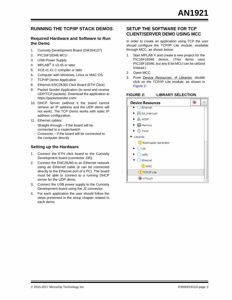
3. From Device Resources Libraries, doubleclick on the TCP/IP Lite module, as shown inFigure 2:
FIGURE 2: LIBRARY SELECTION
2015-2017 Microchip Technology Inc. DS00001921D-page 3

AN1921
4. A TCP Application requires some changes tothe TCP/IP module, as illustrated in Figure 3:
- UDP – not checked- DHCP – not checked. The user must provide
its own static IP configuration- TCP – checked
FIGURE 3: STACK CONFIGURATION
5. The Notifications tab shows different types ofmessages (Figure 4).
- “WARNING” messages are required to be addressed to generate an error free code
- “HINT” messages help the user follow the code generation
- “INFO” messages allow the user to give information about the loaded modules
The Notifications tab shows all the dependencies ofthe TCP/IP stack.
FIGURE 4: NOTIFICATIONS TAB
DS00001921D-page 4 2015-2017 Microchip Technology Inc.

AN1921
6. TCP/IP Lite module requires the Ethernet MAClibrary and Timer1 module, as indicated inFigure 5.
- From Device Resources Libraries Ethernet, double click on MAC
- From Device Resources Peripherals Timer, double click on TMR1
FIGURE 5: STACK DEPENDENCIES SELECTION
7. The device needs to be configured with a 1s tickof system clock. The user shall configure theTimer1 as shown in Figure 6 below:
- Timer Period – 250 ms- Enable Timer Interrupt – Checked- Callback Function Rate – 4
FIGURE 6: TIMER CONFIGURATION
2015-2017 Microchip Technology Inc. DS00001921D-page 5

AN1921
8. Below are the steps required to configure theEthernet MAC module (Figure 7):
- In the Easy Setup window, the user should select the ENC28J60 controller from the drop down selection box. The ENC28J60 controller is based on the Serial Peripheral Interface. The Curiosity Development board (DM164137) supports the MSSP1 – SPI module interface on the J35 connector.
FIGURE 7: MAC LIBRARY CONFIGURATION
9. The user shall add the MSSP1 module, asshown in Figure 8:
- From Device Resources Peripherals MSSP, double click on MSSP1
FIGURE 8: MAC LIBRARY DEPENDENCY SELECTION
10. Steps required to configure MSSP1 module areshown in Figure 9:
- Mode – SPI Master- Input Data Sampled at – End- Clock Edge – Active to Idle
FIGURE 9: SPI CONFIGURATION
11. The user shall use the ADC module to send thepotentiometer data over TCP, as shown inFigure 10.
- From Device Resources Peripherals ADC, double click on ADC
FIGURE 10: ADC MODULE SELECTION
DS00001921D-page 6 2015-2017 Microchip Technology Inc.

AN1921
12. The ADC module should be configured(Figure 11) with:
- Clock Source – FOSC/4- Result Alignment – Right
FIGURE 11: ADC MODULE CONFIGURATION
2015-2017 Microchip Technology Inc. DS00001921D-page 7

AN1921
13. Steps required to configure the Pin Manager(Figure 12):
• MSSP1 module Pin configuration:- SCK1 – output Port RB6- SDI1 – input Port RB4- SDO1 – output - Port RC7
• MAC module Pin configuration- ETH_CS – for the ENC28J60 controller -
output Port RC6• ADC module Pin configuration:
- ANx – input Port RC0- From Project Resources System Pin
Module, the user can provide a custom name to the AN0 channel ex: Pot
• Configure Pin Manager for LED on Curiosity board- Pin module – output Port RA5- From Project Resources System Pin
Module, the user can provide a custom name to the RA5 Pin ex: Toggle_Led
FIGURE 12: PIN FUNCTIONS AND NAMES
14. All the required configurations were made andthe user can click the Generate button.
DS00001921D-page 8 2015-2017 Microchip Technology Inc.
AN1921
SIMPLE TCP CLIENT DEMO IMPLEMENTATION
Overview
This is a simple TCP client implementation that willconnect to a server that runs on a computer on port 60.The user needs to modify the server IP address in thefirmware. Once the connection is established, the clientwill send status packets to the server every 2 seconds.The packets sent by the client contain potentiometervalue and LED status. From the server, the user canalso turn the LED on or off on the board, using the GUIpush buttons. In this demo any button will trigger thesame LED.
For this demo there is only one active connectionimplemented, but the TCP/IP stack supports multipleTCP connections on the same board. For each newconnection the user needs to create a new socket, anRx buffer, and try to connect to the server. This demohas been set up to run on the Curiosity board.
The TCP Client demo will try to connect to the serverevery two seconds. This was implemented so the usercan easily watch and analyze the packets usingWireshark protocol analyzer.
Setting up the Software for the TCP Client Demo
1. The user should find the IP address of thecomputer where the TCP/IP server Java demoapplication runs on.
2. Use the TCP/IP Lite library from the previouslycreated project.
3. Add the tcp_client_demo.c andtcp_client_demo.h files to the project.
4. In main(), the user should callTCP_Client_Initialize() to add theserver IP address and port number. The IPaddress is the one from step 1, as shown inExample 1.
EXAMPLE 1: SETTING SERVER LOCATION
5. In main(), the user shall enable the Global andPeripheral Interrupts.
6. In while(1) loop, the Network_Manage()command must be called. It is an API whichpolls the Ethernet controller for new packets andprocesses them.
7. In while(1) loop, the DEMO_TCP_Client()command must be called to handle the socketstates of the Client connected to the server.
8. The project must be compiled using XC8.
9. Using MPLAB X, the user can program thefirmware on the PIC16F18346 on the CuriosityDevelopment board.
10. If the IP address configured in MCC and the IPaddress of the computer where the TCP/IPserver runs on are both unique, valid and in thesame network, they must be able to exchangepackets. The user can test this by sending ICMPmessages (using the ping command).
11. Start the TCP/IP demo Java application on thecomputer, as shown in Figure 13.
12. Go to the TCP Server Demo tab.
13. Go to the Server Local Port and change theport number to 60.
14. Push the Listen button (The status will bechanged to “Listen...” and the button should bereplaced by one with a Disconnect option).
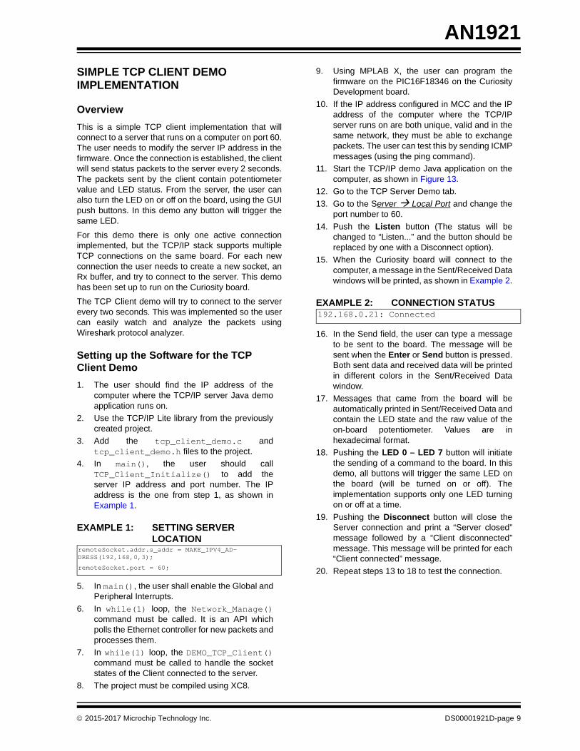
15. When the Curiosity board will connect to thecomputer, a message in the Sent/Received Datawindows will be printed, as shown in Example 2.
EXAMPLE 2: CONNECTION STATUS
16. In the Send field, the user can type a messageto be sent to the board. The message will besent when the Enter or Send button is pressed.Both sent data and received data will be printedin different colors in the Sent/Received Datawindow.
17. Messages that came from the board will beautomatically printed in Sent/Received Data andcontain the LED state and the raw value of theon-board potentiometer. Values are inhexadecimal format.
18. Pushing the LED 0 – LED 7 button will initiatethe sending of a command to the board. In thisdemo, all buttons will trigger the same LED onthe board (will be turned on or off). Theimplementation supports only one LED turningon or off at a time.
19. Pushing the Disconnect button will close theServer connection and print a “Server closed”message followed by a “Client disconnected”message. This message will be printed for each“Client connected” message.
20. Repeat steps 13 to 18 to test the connection.
remoteSocket.addr.s_addr = MAKE_IPV4_AD-DRESS(192,168,0,3);
remoteSocket.port = 60;
192.168.0.21: Connected
2015-2017 Microchip Technology Inc. DS00001921D-page 9

AN1921
FIGURE 13: MICROCHIP TCP CLIENT DEMO IN JAVA APPLICATION
TCP Client Demo Firmware – Buffer Creation
Before starting the Client, the user needs to create thesocket and also, at least, the Rx buffer, as shown inExample 3. The Tx buffer will be created by the userand passed to the TCP stack when it is ready to besent.
EXAMPLE 3: SOCKET CREATION
TCP Client Implementation
The steps required to start and implement the TCPClient are as follows:
1. Initialize the TCP stack. The function should be called before any other TCP function is called. It is done automatically through Network_Init() by the MCC’s SYSTEM_Initialize() function.
TCP_Init();
2. Set the IP address and port number. The userneeds to provide the port number to connect to(this is the port number where the server listenson) and the IP address of the computer wherethe TCP/IP server Java demo application runson. This function should be called before thewhile(1) loop.
TCP_Client_Initialize();
3. Check the status of the socket. This functionchecks if the pointer provided as parameter isregistered internally to the TCP/IP stack as asocket. If the pointer is a valid socket, thefunction will return the state of that socket. Thepossible states of the socket are defined in thetcpv4.h file.
socket_state = TCP_SocketPoll(&port7TCB);
4. Insert and initialize the socket in order to createthe connection. All the necessary information forthe TCP connection is kept here.
TCP_SocketInit(&port60TCB);
5. Set the local port for the client. This step is notmandatory, as the TCP stack will use the nextavailable port number as a local port. The userneeds to use TCP_Bind() to make sure that acertain port number will be used when theconnection is initiated. This is useful when theserver accepts connections only from a certainport number.
TCP_Bind(&port60TCB, 1024);
6. Add the Rx buffer to the socket. The function willinsert the buffer into the socket. It will be used forsaving the received data.
TCP_InsertRxBuffer(&port60TCB, rxdataPort60, sizeof(rxdataPort60));
7. Start the Client by calling the TCP_Connect()function that will initiate the TCP connectprocedure for connecting to the server. If theTCP handshake is successful, the user canexchange data with the remote server over theTCP connection.
TCP_Connect(&port60TCB, &remoteSocket);
8. Close a TCP connection. If the connectionfailed, the Client should abort the connectionand close the socket. The user should initiate anew TCP connect procedure every twoseconds. This function will close the TCPconnection. The user needs to check the socketstate periodically, until the socket is in closedstate. When the socket is in closed state, the Rxand Tx buffers can be safely reused.
TCP_Close(&port60TCB);
// create the socket for the TCP Client
tcpTCB_t port60TCB;
// create the TX and RX buffers
uint8_t rxdataPort60[50];
uint8_t txdataPort60[80];
DS00001921D-page 10 2015-2017 Microchip Technology Inc.

AN1921
9. Check if the Tx buffer was sent correctly. Thisfunction needs to be called before trying to sendanything, because the socket can handle onlyone buffer at a time.
TCP_SendDone(&port60TCB);
10. Read available bytes in Rx buffer and make thebuffer user ready. The function below will returnthe number of bytes available in the buffer. Aftercalling this function, the user can access thebuffer in a safe way. Once the function is called,the stack will not save further received data intothis Rx buffer. The user should provide, asquickly as possible, another Rx buffer to thestack (in order to avoid packet retransmission).
rxLen = TCP_GetReceivedData(&port60TCB);
11. Send the buffer to the remote machine. The APIwill allow the user to send data over an activeTCP connection. The data cannot be sent if theconnection is not established between the localand remote host.
TCP_Send(&port60TCB, txdataPort60, txLen);
12. Remove the socket. When the socket is closed,if the user wants to remove the socket from theinternal socket list, the following API will removethe pointer.
TCP_SocketRemove(&port60TCB);
13. Background task. The function below needs tobe called periodically by the application, in orderto handle the timeouts from the TCP stack. TheTCP background task is called once per secondto handle the TCP stack timeouts.
TCP_Update(); // handle timeouts
2015-2017 Microchip Technology Inc. DS00001921D-page 11

AN1921
Source Code for the TCP Client Implementation
The TCP Client demo code in Example 4 (source codeand prebuilt hex file) is available as download onwww.microchip.com.
Software License AgreementThe software supplied herewith by Microchip Technology Incorporated (the “Company”) is intended and supplied to you, theCompany’s customer, for use solely and exclusively with products manufactured by the Company.The software is owned by the Company and/or its supplier, and is protected under applicable copyright laws. All rights are reserved.Any use in violation of the foregoing restrictions may subject the user to criminal sanctions under applicable laws, as well as to civilliability for the breach of the terms and conditions of this license.THIS SOFTWARE IS PROVIDED IN AN “AS IS” CONDITION. NO WARRANTIES, WHETHER EXPRESS, IMPLIED OR STATU-TORY, INCLUDING, BUT NOT LIMITED TO, IMPLIED WARRANTIES OF MERCHANTABILITY AND FITNESS FOR A PARTICU-LAR PURPOSE APPLY TO THIS SOFTWARE. THE COMPANY SHALL NOT, IN ANY CIRCUMSTANCES, BE LIABLE FORSPECIAL, INCIDENTAL OR CONSEQUENTIAL DAMAGES, FOR ANY REASON WHATSOEVER.
DS00001921D-page 12 2015-2017 Microchip Technology Inc.

AN1921
EXAMPLE 4: TCP CLIENT DEMO SOURCE CODEvoid DEMO_TCP_Client(void)
{
// create the socket for the TCP Client
static tcpTCB_t port60TCB;
// create the TX and RX Client's buffers
static uint8_t rxdataPort60[50];
static uint8_t txdataPort60[80];
static time_t t_client = 0;
static time_t socketTimeout = 0;
uint16_t rx_len;
sockaddr_in_t remoteSocket;
socketState_t socketState;
rx_len = 0;
socketState = TCP_SocketPoll(&port60TCB);
time(&t_client);
switch(socketState)
{
case NOT_A_SOCKET:
// Inserting and initializing the socket
TCP_SocketInit(&port60TCB);break;
case SOCKET_CLOSED:
// if the socket is closed we will try to connect again
// try to connect once at 2 seconds
socketTimeout = t_client + 2;
TCP_InsertRxBuffer(&port60TCB,rxdataPort60, sizeof(rxdataPort60));
TCP_Connect(&port60TCB, &remoteSocket);
break;
case SOCKET_IN_PROGRESS:
// close the socket
if(t_client >= socketTimeout)
{
TCP_Close(&port60TCB);
}
break;
2015-2017 Microchip Technology Inc. DS00001921D-page 13

AN1921
EXAMPLE 4: TCP CLIENT DEMO SOURCE CODE (CONTINUED)case SOCKET_CONNECTED:
// implement an echo client over TCP
// check if the previous buffer was sent
if (TCP_SendDone(&port60TCB))
{
rx_len = TCP_GetReceivedData(&port60TCB);
// handle the incoming data
if(rx_len > 0)
{
/*
…………………………………………………………………………….
LED Command parsing and LCD updates was removed from this example.
The full code is available in the source code.
…………………………………………………………………………….
*/
// reuse the RX buffer
TCP_InsertRxBuffer(&port60TCB, rxdataPort60, sizeof(rxdataPort60));
}
if(t_client >= socketTimeout)
{
// send board status message only once at 2 seconds
socketTimeout = t_client + 2;
/*
…………………………………………………………………………….
Composing the TX message in the TX buffer was removed from this example.
The full code is available in the source code.
…………………………………………………………………………….
*/
//send data back to the source
TCP_Send(&port60TCB, txdataPort60, strlen(txdataPort60));
}
}
break;
case SOCKET_CLOSING:
//remove the used socket form the list
TCP_SocketRemove(&port60TCB);
break;
default:
break;
}
}
DS00001921D-page 14 2015-2017 Microchip Technology Inc.

AN1921
SIMPLE TCP SERVER DEMO IMPLEMENTATION
Overview
This is a simple TCP echo server implementation,listening on port 7. The Server is started on theCuriosity board and it will wait for any incomingconnection. The Server will echo back all the receiveddata once the connection with a client is established.Only one active connection will be created for thisdemo, but the TCP/IP stack supports multiple TCPconnections on the same board. The user needs tocreate a new Server (create buffers, initialize and startlistening) for each new connection.
Setting up the Software for the TCP Server Demo
1. The user should create a project as it wasshown in Section “Setup the Software forTCP Client/Server Demo Using MCC”, thistime excluding steps 11 and 12. The Serverdoes not need an ADC module or LEDs to betoggled.
2. Add the tcp_server_demo.c andtcp_server_demo.h files to the project.
3. In the main() function, the user will enable theGlobal and Peripheral Interrupts.
4. In while(1) loop, the Network_Manage()function must be called. It is an API which pollsthe Ethernet controller for new packets andprocesses them.
5. In while(1) loop, the DEMO_TCP_EchoServer()function must be called to open the socket and listenfor incoming clients.
6. The project must be compiled using XC8.
7. Using MPLAB X, the user can program thefirmware to the PIC16F18346 on the CuriosityDevelopment board.
8. Start the TCP/IP demo Java application on thecomputer (see Figure 14).
9. Go to the TCP Client Demo tab.
10. Go to the “Server IP Address” and set the IPaddress and the port number to 7. The IPaddress is static and it was configured usingMCC.
11. Click on the Connect button.
12. When the computer is connected to theCuriosity board, a message in the Sent/Received Data windows will be printed, asshown in Example 5.
EXAMPLE 5: INITIAL LOG MESSAGE
13. The user can type in the Send window and press
Enter from keyboard or push the Send button tosend the string. Both sent and received data willbe printed with different colors in the Sent/Received Data window.
14. Pushing the Disconnect button will close theTCP connection. A “Connection closed”message will be printed.
15. Repeat steps 9 to 13 to test the connectionusing different strings length.
16. To generate TCP traffic to the board the ECHOback received message button should beenabled. The Send text box should be filled withthe desired message to be sent to the board.Pushing the Send button will initiate the dataexchange. To stop the TCP traffic the EchoBack received message button should bepushed again. In this case, in the Sent/ReceivedData window, only the received messages willbe printed.
FIGURE 14: MICROCHIP TCP CLIENT DEMO FOR JAVA APPLICATION
Connected to 192.168.0.21 Port: 7
2015-2017 Microchip Technology Inc. DS00001921D-page 15

AN1921
TCP Server Demo Firmware – Buffer Creation
Before starting the Server, the user needs to create thesocket and also, at least, the Rx buffer. The Tx bufferwill be created by the user and passed to the TCP stackwhen it is ready to be sent.
EXAMPLE 6: SOCKET CREATION
TCP Server Implementation
These are the steps required to implement the TCPServer:
1. Initialize the TCP stack. The function should becalled before any other TCP function. It is doneautomatically through Network_Init() by theMCC’s SYSTEM_Initialize() function.
TCP_Init();
2. Check the status of the socket: This functionchecks if the pointer provided as parameter isregistered internally to the TCP/IP stack as asocket. If the pointer is a valid socket, thefunction will return the state of that socket. Thepossible states of the socket are defined in thetcpv4.h file.
socket_state = TCP_SocketPoll(&port7TCB);
3. Insert and initialize the socket in order to createthe connection. All the necessary information forthe TCP connection is kept here.
TCP_SocketInit(&port7TCB);
4. Assign the local port for the Server. The functionwill assign a port for the socket to listen on. TheServer will listen on this port for any incomingconnections. The TCP stack will automaticallyallocate a port number to listen on if a portnumber is not supplied by the user.
TCP_Bind(&port7TCB, 7);
5. Add the receive buffer to a socket. The functionwill insert the buffer into the socket for storingthe received data.
TCP_InsertRxBuffer(&port7TCB,
rxdataPort7, sizeof(rxdataPort7));
6. Start the TCP Server. The function will set theTCP stack to listen to a port for a connectionrequest. If the TCP handshake completessuccessfully, the user can exchange data withthe remote over the TCP connection. Only oneconnection request is accepted at a time. The
TCP stack can handle multiple connections for aparticular port number. But for each newconnection the user needs to create a newsocket, an Rx buffer, and start a new instance ofthe Server for the same port.
TCP_Listen(&port7TCB);
7. Check the status of the socket. This functionchecks if the pointer provided as parameter isalready registered to the TCP/IP stack as asocket. If the pointer is a valid socket, thefunction will return the state of that socket. Thepossible states of the socket are defined in thetcpv4.h file.
socket_state = TCP_SocketPoll(&port7TCB);
8. Check if the Tx buffer was sent correctly (thismeans that the remote acknowledged all thereceived bytes). This function needs to be calledbefore trying to send anything, because thesocket can handle only one buffer at a time.
TCP_SendDone(&port7TCB);
9. Check if there is any data received in the socket.The function will return the number of bytesavailable in the Rx buffer.
rxLen = TCP_GetRxLength(&port7TCB);
10. Read how many bytes are available in the Rxbuffer and make the buffer ready to use. Thefunction will return the number of bytes availablein the buffer. After calling this function, the usercan access the buffer in a safe way. Once thefunction is called, the stack will not save anyfurther data received into this Rx buffer. Theuser should provide, as fast as possible, anotherRx buffer to the stack, in order to avoid packetretransmission.
rxLen = TCP_GetReceivedData(&port7TCB);
11. Send the buffer to the remote machine. The APIwill allow the user to send data over an activeTCP connection. The data cannot be sent if theconnection is not established between the localand the remote host.
TCP_Send(&port7TCB, txdataPort7, txLen);
12. Close the TCP connection. Socket connectionclosing will happen after the TCP connectionhandshake is done (the connection closing isnot done right away). The user needs to checkthe socket state periodically, until the socket is inClosed state. When the socket is in Closedstate, the Rx and the Tx buffers can be safelyreused.
TCP_Close(&port7TCB)
// create the socket for the TCP Server
tcpTCB_t port7TCB;
// create the TX and RX buffers
uint8_t rxdataPort7[20];
uint8_t txdataPort7[20];
DS00001921D-page 16 2015-2017 Microchip Technology Inc.

AN1921
13. Remove the socket. If the user wants to removethe socket from the internal socket list when thesocket is closed, the following API will removethe pointer.
TCP_SocketRemove(&port7TCB)
14. Background task. This function needs to becalled periodically by the application, in order tohandle the timeouts from the TCP stack. TheTCP background task is called once per secondto handle the TCP stack timeouts.
TCP_Update();// handle timeouts
Source Code for the TCP Server Implementation
The TCP Client demo code in Example 7 (source codeand prebuilt hex file) is available as download onwww.microchip.com.
EXAMPLE 7: TCP ECHO SERVER IMPLEMENTATIONvoid DEMO_TCP_echo_server(void)
{
// create the socket for the TCP Server
static tcpTCB_t port7TCB;
// create the TX and RX buffers
static uint8_t rxdataPort7[20];
static uint8_t txdataPort7[20];
uint16_t rxLen, txLen, i;
socket_state_t socket_state;
rxLen = 0;
// checking the status of the socket
socket_state = TCP_SocketPoll(&port7TCB);
switch(socket_state)
{
case NOT_A_SOCKET:
//Inserting and initializing the socket
TCP_SocketInit(&port7TCB);
case SOCKET_CLOSED:
//configure the local port
TCP_Bind(&port7TCB, 7);
// add receive buffer
TCP_InsertRxBuffer(&port7TCB,rxdataPort7, sizeof(rxdataPort7));
// start the server
TCP_Listen(&port7TCB);
break;
2015-2017 Microchip Technology Inc. DS00001921D-page 17

AN1921
EXAMPLE 7: TCP ECHO SERVER IMPLEMENTATION (CONTINUED)case SOCKET_CONNECTED:
// check if the buffer was sent, if yes we can reuse the //buffer
if(TCP_SendDone(&port7TCB))
{
// check to see if there are any received data
rxLen = TCP_GetRxLength(&port7TCB);
if(rxLen > 0)
{
//make sure it safe to use the receive buffer
rxLen = TCP_GetReceivedData(&port7TCB);
//simulate some buffer processing copy from //the RX buffer to the TX buffer
for(i = 0; i < rxLen; i++)
{
txdataPort7[i] = rxdataPort7[i];
}
// reuse the rx buffer
TCP_InsertRxBuffer(&port7TCB,rxdataPort7, sizeof(rxdataPort7));
txLen = rxLen;
//send data back to the source
TCP_Send(&port7TCB, txdataPort7, txLen);
}
}
break;
case SOCKET_CLOSING:
TCP_SocketRemove(&port60TCB);
break;
default:
// we should not end up here
break;
}
}
DS00001921D-page 18 2015-2017 Microchip Technology Inc.

AN1921
UDP DEMO
Overview
This is a UDP Client and Server implementation. Itconsists of UDP Send (UDP Client) and UDP Receive(UDP Server) implementations. As UDP Send, theCuriosity Development board sends potentiometerreadings as UDP packets. As UDP Receive, theCuriosity Development board starts listening to anyincoming UDP packets such as toggle LEDs on port65531. The port numbers can be anything between in0 to 65535, but some of them are reserved or alreadyregistered. Therefore, it is recommended to choose aport between 49152 to 65535, since all of them arefree.
Setting up the Software for UDP Send/Receive (Client/Server) Demo
1. Start MPLAB X and create a new project for thedevice PIC16F18346.
2. Load the MCC module.
3. Go to Device Resources, and under Librariesselect TCP/IP Lite module.
4. Load the TCP/IP Lite module.
5. The Notifications tab shows different types ofmessages:
- “WARNING” messages are required to be implemented to generate an error free code
- “HINT” messages help the user follow the code generation
- “INFO” messages allow the user to give information about the modules loaded
6. Go to Device Resources, under Libraries selectEthernet MAC module.
7. Load the MAC module.
8. In the Easy Setup, select the ENC28J60controller from the drop down selection box.
9. The ENC28J60 controller is based on SerialPeripheral Interface. So, as per the CuriosityDevelopment board schematics, the “MSSP1 –SPI module” interface is supported on theconnector J35.
10. Go to Device Resources, under Peripheralsselect MSSP1 module.
11. Load MSSP1 module and configure to SPIMaster mode and select the Clock Edge toActive to Idle mode, and set Input Data Sampledat “End”.
12. Go to Device Resources, and under Peripheralsselect TMR1 module.
13. Update the Timer Period to 250 ms. Enable theTimer Interrupt and update the CallbackFunction Rate to 4 to generate a 1s period. Thisfeature is required to configure the device with a1s tick of system clock.
14. Configure the ADC module to send thepotentiometer data over UDP. Go to DeviceResources, under Peripherals select ADCmodule. Load the ADC module.
15. In the ADC module, configure Clock Source toFOSC/4, and Result Alignment to right.
16. Configure the Pin Manager:
• MSSP1 module Pin Configuration- SCK1 – output Port RB6- SDI1 – input Port RB4- SDO1 – output Port RC7
• MAC module Pin Configuration • ETH_CS (for the ENC28J60 controller) – output
Port RC6• ADC module Pin Configuration
- ANx – input PORT RC0- From Project Resource System Pin
Module, the user can provide a custom name to the AN0 channel, for example: Pot
• Configure the Pin Manager for LEDs on Curiosity board:- Pin module – output Port RA5- From Project Resource System Pin
Module, the user can provide a custom name to the RA5 Pin, for example: Toggle_Led
17. Click on Generate button to generate the code.
18. Add the udp_demo.c and udp_demo.h files tothe project.
19. In the main() function, the user should enablethe Global and Peripheral interrupts.
20. In main(), call the POT_UDP_Initialize()API in the udp_demo.c file to initialize thepotentiometer and UDP server packet i.e., UDPserver (destination) Port Number – 65531, UDPServer Address – computer IP address(Destination address), and UDP Client (Source)Port Number – 65533.
21. In while(1) loop, call the Network_Mange()API which polls the Ethernet controller for newpackets and processes them.
22. The project must be compiled using XC8 andprogram the firmware to the PIC16F18346 onthe Curiosity Development board.
23. Start the Packet Sender application (Figure 15)on the computer.
2015-2017 Microchip Technology Inc. DS00001921D-page 19

AN1921
FIGURE 15: PACKET SENDER INTERFACE
24. Go to File Settings Network, enable theUDP Server and update the port to 65531.
25. Turn the knob on the Curiosity Developmentboard. The board sends UDP packets to displaythe potentiometer reading in volts.
26. In the Packet Sender application, send a UDPpacket to turn the LEDs on the CuriosityDevelopment board to toggle.
• Name – UDP Led1 Send• ASCII – L1• Address – board’s IP address. This can be
accessed from the D-Discover O-Offer R- Request A-Acknowledgment process using the Wireshark analyzer tool.
• Port – 65531• Select the UDP protocol• Click on Save to save this packet
DS00001921D-page 20 2015-2017 Microchip Technology Inc.

AN1921
FIGURE 16: UDP PACKET CONFIGURATION
27. In Packet Sender, click on the Send button ofthe saved UDP packets to toggle the LED on theCuriosity board.
28. Repeat steps 25 and 27 to verify the UDP sendand UDP receive packets on port 65531.
UDP Send Implementation
In order to start the UDP packet, the following steps arerequired:
1. Start the UDP Packet
The function will start the UDPv4 Packet, which startsthe IPv4 packet and writes the UDP Header. The UDPHeader fields – checksum and Data length – areinitially set to ‘0’.
- UDP_Start(uint32_t destIP, uint16_t srcPort, uint16_t destPort);
2. Write the UDP Packet
There are six methods of writing a UDP packet,depending on the size and order of data written.
- UDP_WriteBlock(uint8_t* data, uint16_t length) – Writes a block of data
- UDP_Write8(uint8_t data) – Writes 1 byte of data
- UDP_Write16(uint16_t data); - Writes 2 bytes of data in Host Order
- UDP_Write24(uint32_t data); - Writes 3 bytes of data in Host Order
- UDP_Write32(uint32_t data); - Writes 4 bytes of data in Host Order
- UDP_String(const char *string)– Writes String in Network Order
3. Send the UDP Packet
The function will insert the total payload length into theUDP header, compute the checksum of the UDPpacket and send the packet on the wire.
- UDP_Send();
2015-2017 Microchip Technology Inc. DS00001921D-page 21

AN1921
UDP Receive Implementation
In order to receive the UDP packet, the following stepsare required:
1. Port Handling
In the udpv4_port_handler_table.c file, theUDP_CallBackTable[] function needs to beupdated with the receiving port number and its callbackfunction.
EXAMPLE 8: PORT HANDLING
2. Receive the UDP Packet
At first, check for the valid checksum. Any UDP packetswith invalid checksums are discarded. If the checksumis correct, the function will check for the port number tobe matched in UDP_CallBackTable[]. If the portnumber and the corresponding function handler(callback) are valid in the table, the length of UDPpayload is passed as parameter to the callback. AnyUDP packet with invalid port number will respond withan “ICMP PORT UNREACHABLE” message, if “ICMPPort Unreachable” option is selected in the MCC whileconfiguring the stack; else the UDP packet isdiscarded.
- UDP_Receive(uint16_t udpcksm);
3. Read the UDP Packet
There are five methods of reading a UDP packet,depending on the size and order of data.
- UDP_ReadBlock(uint8_t* data, uint16_t length) – Reads a block of data
- UDP_Read8() – Reads 1 byte of data- UDP_Read16() - Reads 2 bytes of data in
Host Order- UDP_Read24() - Reads 3 bytes of data in
Host Order- UDP_Read32() - Reads 4 bytes of data in
Host Order
typedef struct{ uint16_t portNumber; ip_receive_function_ptr callBack;}udp_handler_t;
const udp_handler_t UDP_CallBackTable [] = \{
{portNumber, &callback} };
DS00001921D-page 22 2015-2017 Microchip Technology Inc.

AN1921
Source Code for the UDP Client/Server Implementation
The UDP demo code (source code and prebuilt hexfile) is available as download on www.microchip.com.
EXAMPLE 9: UDP CLIENT IMPLEMENTATION
EXAMPLE 10: UDP SERVER IMPLEMENTATION
void UDP_DEMO_Send (void)
{
error_msg ret = ERROR;
potCurrResult = (ADCC_GetSingleConversion(Pot)/10);
if(...)
{
...
ret = UDP_Start(udpPacket.destinationAddress, udpPacket.sourcePortNumber,udpPacket.destinationPortNumber);
if(ret = SUCCESS)
{
UDP_Write16(potCurrResult);
UDP_Send();
}
}
}
const udp_handler_t UDP_CallBackTable [] = \
{
{68, DHCP_Handler},
{65531, UDP_DEMO_Recv}
};
void UDP_DEMO_Recv (int length)
{
...
UDP_ReadBlock(&data,sizeof(data));
/*
...
Process the Receive Buffer data
*/
}
2015-2017 Microchip Technology Inc. DS00001921D-page 23

AN1921
CONCLUSION
This application note presents some very simplesoftware solutions for implementing a TCP Server, aTCP Client and exchange data over UDP based on theMicrochip lightweight TCP/IP stack. The TCP/IP stackprovides space efficiency and modular implementationallowing to add network connectivity to embeddedsystems with limited resources.
DS00001921D-page 24 2015-2017 Microchip Technology Inc.

AN1921
APPENDIX A: REFERENCES
1. User Datagram Protocol, RFC 768
2. Internet Protocol, DARPA Internet ProgramProtocol Specification, RFC 791
3. Internet Control Message Protocol, DARPAInternet Program Protocol Specification, RFC792
4. Transmission Control Protocol, DARPA InternetProgram Protocol Specification, RFC 793
5. Requirements for Internet Hosts,Communication Layers, RFC 1122
6. An Ethernet Address Resolution Protocol orConverting Network Protocol Addresses to48 bit Ethernet Address for Transmission onEthernet Hardware, RFC 826
7. Domain Names – Implementation andSpecification, RFC 1035
8. Clarifications to the DNS Specification, RFC2181
9. Service Name and Transport Protocol PortNumber Registry (www.iana.org)
2015-2017 Microchip Technology Inc. DS00001921D-page 25

AN1921
APPENDIX B: FLOWCHART FOR TCP CLIENT DEMO
Since the demo containing the TCP/IP stack is verylarge, the software flowchart shown in Figure B-1 isonly for the main application with a focus on the TCPClient routine found in the main.c file.
FIGURE B-1: FLOWCHART FOR TCP CLIENT DEMO
DS00001921D-page 26 2015-2017 Microchip Technology Inc.

AN1921
FIGURE B-2: FLOWCHART FOR TCP SERVER DEMO
2015-2017 Microchip Technology Inc. DS00001921D-page 27

AN1921
FIGURE B-3: FLOWCHART FOR UDP DATA EXCHANGE DEMO
DS00001921D-page 28 2015-2017 Microchip Technology Inc.

Note the following details of the code protection feature on Microchip devices:
• Microchip products meet the specification contained in their particular Microchip Data Sheet.
• Microchip believes that its family of products is one of the most secure families of its kind on the market today, when used in the intended manner and under normal conditions.
• There are dishonest and possibly illegal methods used to breach the code protection feature. All of these methods, to our knowledge, require using the Microchip products in a manner outside the operating specifications contained in Microchip’s Data Sheets. Most likely, the person doing so is engaged in theft of intellectual property.
• Microchip is willing to work with the customer who is concerned about the integrity of their code.
• Neither Microchip nor any other semiconductor manufacturer can guarantee the security of their code. Code protection does not mean that we are guaranteeing the product as “unbreakable.”
Code protection is constantly evolving. We at Microchip are committed to continuously improving the code protection features of ourproducts. Attempts to break Microchip’s code protection feature may be a violation of the Digital Millennium Copyright Act. If such actsallow unauthorized access to your software or other copyrighted work, you may have a right to sue for relief under that Act.
Information contained in this publication regarding deviceapplications and the like is provided only for your convenienceand may be superseded by updates. It is your responsibility toensure that your application meets with your specifications.MICROCHIP MAKES NO REPRESENTATIONS ORWARRANTIES OF ANY KIND WHETHER EXPRESS ORIMPLIED, WRITTEN OR ORAL, STATUTORY OROTHERWISE, RELATED TO THE INFORMATION,INCLUDING BUT NOT LIMITED TO ITS CONDITION,QUALITY, PERFORMANCE, MERCHANTABILITY ORFITNESS FOR PURPOSE. Microchip disclaims all liabilityarising from this information and its use. Use of Microchipdevices in life support and/or safety applications is entirely atthe buyer’s risk, and the buyer agrees to defend, indemnify andhold harmless Microchip from any and all damages, claims,suits, or expenses resulting from such use. No licenses areconveyed, implicitly or otherwise, under any Microchipintellectual property rights unless otherwise stated.
2015-2017 Microchip Technology Inc.
Microchip received ISO/TS-16949:2009 certification for its worldwide headquarters, design and wafer fabrication facilities in Chandler and Tempe, Arizona; Gresham, Oregon and design centers in California and India. The Company’s quality system processes and procedures are for its PIC® MCUs and dsPIC® DSCs, KEELOQ® code hopping devices, Serial EEPROMs, microperipherals, nonvolatile memory and analog products. In addition, Microchip’s quality system for the design and manufacture of development systems is ISO 9001:2000 certified.
QUALITY MANAGEMENT SYSTEM CERTIFIED BY DNV
== ISO/TS 16949 ==
Trademarks
The Microchip name and logo, the Microchip logo, AnyRate, AVR, AVR logo, AVR Freaks, BeaconThings, BitCloud, chipKIT, chipKIT logo, CryptoMemory, CryptoRF, dsPIC, FlashFlex, flexPWR, Heldo, JukeBlox, KEELOQ, KEELOQ logo, Kleer, LANCheck, LINK MD, maXStylus, maXTouch, MediaLB, megaAVR, MOST, MOST logo, MPLAB, OptoLyzer, PIC, picoPower, PICSTART, PIC32 logo, Prochip Designer, QTouch, RightTouch, SAM-BA, SpyNIC, SST, SST Logo, SuperFlash, tinyAVR, UNI/O, and XMEGA are registered trademarks of Microchip Technology Incorporated in the U.S.A. and other countries.
ClockWorks, The Embedded Control Solutions Company, EtherSynch, Hyper Speed Control, HyperLight Load, IntelliMOS, mTouch, Precision Edge, and Quiet-Wire are registered trademarks of Microchip Technology Incorporated in the U.S.A.
Adjacent Key Suppression, AKS, Analog-for-the-Digital Age, Any Capacitor, AnyIn, AnyOut, BodyCom, CodeGuard, CryptoAuthentication, CryptoCompanion, CryptoController, dsPICDEM, dsPICDEM.net, Dynamic Average Matching, DAM, ECAN, EtherGREEN, In-Circuit Serial Programming, ICSP, Inter-Chip Connectivity, JitterBlocker, KleerNet, KleerNet logo, Mindi, MiWi, motorBench, MPASM, MPF, MPLAB Certified logo, MPLIB, MPLINK, MultiTRAK, NetDetach, Omniscient Code Generation, PICDEM, PICDEM.net, PICkit, PICtail, PureSilicon, QMatrix, RightTouch logo, REAL ICE, Ripple Blocker, SAM-ICE, Serial Quad I/O, SMART-I.S., SQI, SuperSwitcher, SuperSwitcher II, Total Endurance, TSHARC, USBCheck, VariSense, ViewSpan, WiperLock, Wireless DNA, and ZENA are trademarks of Microchip Technology Incorporated in the U.S.A. and other countries.
SQTP is a service mark of Microchip Technology Incorporated in the U.S.A.
Silicon Storage Technology is a registered trademark of Microchip Technology Inc. in other countries.
GestIC is a registered trademark of Microchip Technology Germany II GmbH & Co. KG, a subsidiary of Microchip Technology Inc., in other countries.
All other trademarks mentioned herein are property of their respective companies.
© 2015-2017, Microchip Technology Incorporated, All Rights Reserved.
ISBN: 978-1-5224-1727-9
DS00001921D-page 29

DS00001921D-page 30 2015-2017 Microchip Technology Inc.
AMERICASCorporate Office2355 West Chandler Blvd.Chandler, AZ 85224-6199Tel: 480-792-7200 Fax: 480-792-7277Technical Support: http://www.microchip.com/supportWeb Address: www.microchip.com
AtlantaDuluth, GA Tel: 678-957-9614 Fax: 678-957-1455
Austin, TXTel: 512-257-3370
BostonWestborough, MA Tel: 774-760-0087 Fax: 774-760-0088
ChicagoItasca, IL Tel: 630-285-0071 Fax: 630-285-0075
DallasAddison, TX Tel: 972-818-7423 Fax: 972-818-2924
DetroitNovi, MI Tel: 248-848-4000
Houston, TX Tel: 281-894-5983
IndianapolisNoblesville, IN Tel: 317-773-8323Fax: 317-773-5453Tel: 317-536-2380
Los AngelesMission Viejo, CA Tel: 949-462-9523Fax: 949-462-9608Tel: 951-273-7800
Raleigh, NC Tel: 919-844-7510
New York, NY Tel: 631-435-6000
San Jose, CA Tel: 408-735-9110Tel: 408-436-4270
Canada - TorontoTel: 905-695-1980 Fax: 905-695-2078
ASIA/PACIFICAsia Pacific OfficeSuites 3707-14, 37th FloorTower 6, The GatewayHarbour City, Kowloon
Hong KongTel: 852-2943-5100Fax: 852-2401-3431
Australia - SydneyTel: 61-2-9868-6733Fax: 61-2-9868-6755
China - BeijingTel: 86-10-8569-7000 Fax: 86-10-8528-2104
China - ChengduTel: 86-28-8665-5511Fax: 86-28-8665-7889
China - ChongqingTel: 86-23-8980-9588Fax: 86-23-8980-9500
China - DongguanTel: 86-769-8702-9880
China - GuangzhouTel: 86-20-8755-8029
China - HangzhouTel: 86-571-8792-8115 Fax: 86-571-8792-8116
China - Hong Kong SARTel: 852-2943-5100 Fax: 852-2401-3431
China - NanjingTel: 86-25-8473-2460Fax: 86-25-8473-2470
China - QingdaoTel: 86-532-8502-7355Fax: 86-532-8502-7205
China - ShanghaiTel: 86-21-3326-8000 Fax: 86-21-3326-8021
China - ShenyangTel: 86-24-2334-2829Fax: 86-24-2334-2393
China - ShenzhenTel: 86-755-8864-2200 Fax: 86-755-8203-1760
China - WuhanTel: 86-27-5980-5300Fax: 86-27-5980-5118
China - XianTel: 86-29-8833-7252Fax: 86-29-8833-7256
ASIA/PACIFICChina - XiamenTel: 86-592-2388138 Fax: 86-592-2388130
China - ZhuhaiTel: 86-756-3210040 Fax: 86-756-3210049
India - BangaloreTel: 91-80-3090-4444 Fax: 91-80-3090-4123
India - New DelhiTel: 91-11-4160-8631Fax: 91-11-4160-8632
India - PuneTel: 91-20-3019-1500
Japan - OsakaTel: 81-6-6152-7160 Fax: 81-6-6152-9310
Japan - TokyoTel: 81-3-6880- 3770 Fax: 81-3-6880-3771
Korea - DaeguTel: 82-53-744-4301Fax: 82-53-744-4302
Korea - SeoulTel: 82-2-554-7200Fax: 82-2-558-5932 or 82-2-558-5934
Malaysia - Kuala LumpurTel: 60-3-6201-9857Fax: 60-3-6201-9859
Malaysia - PenangTel: 60-4-227-8870Fax: 60-4-227-4068
Philippines - ManilaTel: 63-2-634-9065Fax: 63-2-634-9069
SingaporeTel: 65-6334-8870Fax: 65-6334-8850
Taiwan - Hsin ChuTel: 886-3-5778-366Fax: 886-3-5770-955
Taiwan - KaohsiungTel: 886-7-213-7830
Taiwan - TaipeiTel: 886-2-2508-8600 Fax: 886-2-2508-0102
Thailand - BangkokTel: 66-2-694-1351Fax: 66-2-694-1350
EUROPEAustria - WelsTel: 43-7242-2244-39Fax: 43-7242-2244-393
Denmark - CopenhagenTel: 45-4450-2828 Fax: 45-4485-2829
Finland - EspooTel: 358-9-4520-820
France - ParisTel: 33-1-69-53-63-20 Fax: 33-1-69-30-90-79
France - Saint CloudTel: 33-1-30-60-70-00
Germany - GarchingTel: 49-8931-9700Germany - HaanTel: 49-2129-3766400
Germany - HeilbronnTel: 49-7131-67-3636
Germany - KarlsruheTel: 49-721-625370
Germany - MunichTel: 49-89-627-144-0 Fax: 49-89-627-144-44
Germany - RosenheimTel: 49-8031-354-560
Israel - Ra’anana Tel: 972-9-744-7705
Italy - Milan Tel: 39-0331-742611 Fax: 39-0331-466781
Italy - PadovaTel: 39-049-7625286
Netherlands - DrunenTel: 31-416-690399 Fax: 31-416-690340
Norway - TrondheimTel: 47-7289-7561
Poland - WarsawTel: 48-22-3325737
Romania - BucharestTel: 40-21-407-87-50
Spain - MadridTel: 34-91-708-08-90Fax: 34-91-708-08-91
Sweden - GothenbergTel: 46-31-704-60-40
Sweden - StockholmTel: 46-8-5090-4654
UK - WokinghamTel: 44-118-921-5800Fax: 44-118-921-5820
Worldwide Sales and Service
11/07/16