Embed Size (px)
Citation preview
RSC Advances
REVIEW
Ope
n A
cces
s A
rtic
le. P
ublis
hed
on 0
4 M
ay 2
021.
Dow
nloa
ded
on 3
/25/
2022
9:4
2:09
PM
. T
his
artic
le is
lice
nsed
und
er a
Cre
ativ
e C
omm
ons
Attr
ibut
ion
3.0
Unp
orte
d L
icen
ce.
View Article OnlineView Journal | View Issue
Microbial fuel ce
aCentre for Biosensors, Bioelectronics and
Chemical Engineering, University of Bat
[email protected] Innovation Research Centre (WIRC),
Cite this: RSC Adv., 2021, 11, 16307
Received 10th February 2021Accepted 23rd April 2021
DOI: 10.1039/d1ra01138c
rsc.li/rsc-advances
© 2021 The Author(s). Published by
lls for in-field water qualitymonitoring
Lola Gonzalez Oliasab and Mirella Di Lorenzo *a
The need for water security pushes for the development of sensing technologies that allow online and real-
time assessments and are capable of autonomous and stable long-term operation in the field. In this
context, Microbial Fuel Cell (MFC) based biosensors have shown great potential due to cost-
effectiveness, simplicity of operation, robustness and the possibility of self-powered applications. This
review focuses on the progress of the technology in real scenarios and in-field applications and
discusses the technological bottlenecks that must be overcome for its success. An overview of the most
relevant findings and challenges of MFC sensors for practical implementation is provided. First,
performance indicators for in-field applications, which may diverge from lab-based only studies, are
defined. Progress on MFC designs for off-grid monitoring of water quality is then presented with a focus
on solutions that enhance robustness and long-term stability. Finally, calibration methods and detection
algorithms for applications in real scenarios are discussed.
1. Introduction
Population growth, rapid urbanisation and intensied agricul-tural and industrial activity are increasing water pollutionworldwide.1 More than 80% of wastewaters resulting from theseactivities are discharged into rivers and seas without any treat-ment, resulting in more than one billion people being exposedto unsafe water.2
These unprecedented levels of water pollution can lead tounknown consequences for biota and human health. There is,therefore, a growing need for the development of tools able toeffectively monitor water systems in-eld and to address thedemand for frequent data acquisition on a large spatialcoverage.3 Current water monitoring techniques compriseremote and direct sampling tests.
Remote sensing technologies, including visible, infrared,near-infrared, ultraviolet, radar, microwave, laser-acoustic andlaser-uorescence, provide wide coverage and high precisionimaging capability, but suffer from high costs, interferencesfrom aquatic plants and temperature variations, and slow datacollection.4 Direct eld tests involve in situ determination of keyindicators of water quality, such as pH, conductivity, tempera-ture and dissolved oxygen (DO).5 Sensors for in-eld tempera-ture, pH, and conductivity monitoring are low-cost and easy toimplement. DO sensors, whether optical or electrochemical, arerelatively more expensive and require regular maintenance.6
Biodevices (C3Bio) and Department of
h, Bath, BA2 7AY, UK. E-mail: m.di.
University of Bath, Bath, BA2 7AY, UK
the Royal Society of Chemistry
Other indicators, like nitrates and phosphates, emergingcontaminants or mining products are usually determined usingex situ lab-based analytical methods, i.e. gas/liquid chroma-tography or mass spectroscopy.7,8 While accurate and sensitive,those methods are offline, expensive, time consuming andrequire specialised equipment and highly trained technicians.Moreover, they cannot inform on the bioavailability risk ofpollutants.9
There is therefore the need to develop innovative technolo-gies capable of detecting and monitoring in situ the presence ofpollutants in water. Whole-cell electrochemical biosensors,based on the activity of micro-organisms such as yeast, bacteriaor algae, are a promising technology for online, in situ, moni-toring of bioavailable pollutants in water.10,11 Although lessselective than organelle or enzymatic biosensors, whole-cellsensors are more stable over time and easier to operate.10
In this context, Microbial Fuel Cell (MFC)-based biosensorshave shown great potential.12 MFC biosensors could providegreat resilience and long-term stability,13 are cost-effective andcompatible with self-powered/autonomous operation.14
2. Microbial fuel cells for waterquality monitoring
MFCs are electrochemical devices in which electroactivebacteria convert the energy stored in organic substrates intoelectricity. The system consists of an anode and cathode elec-trode, which are usually physically separated by a membrane. Atthe anode, always biotic, organic carbon is oxidised to CO2,electrons and protons or else, CO2 is photocatalytically reducedto organic molecules.15 The electrons ow through an external
RSC Adv., 2021, 11, 16307–16317 | 16307
RSC Advances Review
Ope
n A
cces
s A
rtic
le. P
ublis
hed
on 0
4 M
ay 2
021.
Dow
nloa
ded
on 3
/25/
2022
9:4
2:09
PM
. T
his
artic
le is
lice
nsed
und
er a
Cre
ativ
e C
omm
ons
Attr
ibut
ion
3.0
Unp
orte
d L
icen
ce.
View Article Online
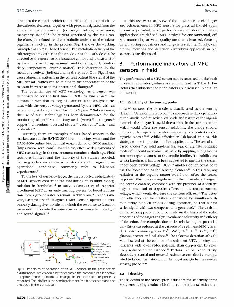
circuit to the cathode, which can be either abiotic or biotic. Atthe cathode, electrons, together with protons migrated from theanode, reduce to an oxidant (i.e. oxygen, nitrate, ferricyanide,manganese oxide).16 The current generated by the MFC can,therefore, be related to the metabolic activity of the micro-organisms involved in the process. Fig. 1 shows the workingprinciples of anMFC-based sensor. Themetabolic activity of themicroorganisms either at the anode or at the cathode can beaffected by the presence of a bioactive compound (a toxicant) orby variations in the operational conditions (e.g. pH, conduc-tivity, temperature, organic matter). This disruption in themetabolic activity (indicated with the symbol X in Fig. 1) cancause abnormal patterns in the current output (the signal of theMFC-sensor), which can be related to the concentration of thetoxicant in water or to the operational changes.17
The potential use of MFC technology as a sensor wasdemonstrated for the rst time in 2003 by Kim et al.18 Theauthors showed that the organic content in the anolyte corre-lates with the output voltage generated by the MFC, with anoutstanding stability in eld for up to 5 years.18 Subsequently,the use of MFC technology has been demonstrated for themonitoring of pH,19 volatile fatty acids (VFAs),20 pathogens,21
copper,22 chromium, iron and nitrate,23 cadmium,24 zinc25 andpesticides.26
Currently, there are examples of MFC-based sensors in themarket, such as the HATOX-2000 biomonitoring system and theHABS-2000 online biochemical oxygen demand (BOD) analyser(https://www.korbi.com). Nonetheless, effective deployments ofMFC technology in the environment remains a challenge. Fieldtesting is limited, and the majority of the studies reported,focusing either on innovative materials and designs or onoperational conditions, commonly refer to lab-basedexperiments.27
To the best of our knowledge, the rst reported in-eld studyof MFC sensors concerned the monitoring of uranium biodeg-radation in boreholes.28 In 2017, Velasquez et al. reporteda sediment MFC as an early warning system for faecal inltra-tion into a groundwater reservoir in Tanzania.29 In the sameyear, Pasternak et al. designed a MFC sensor, operated auton-omously during ve months, in which the response to faecal orurine inltration into the water stream was converted into lightand sound signals.14
Fig. 1 Principles of operation of an MFC sensor. In the presence ofa disturbance, which could be for example the presence of a bioactivecompound (the toxicant), a change in the electrical response isrecorded. The biofilm is the sensing element (the bioreceptor) and theelectrode is the transducer.
16308 | RSC Adv., 2021, 11, 16307–16317
In this review, an overview of the most relevant challengesand achievements in MFC sensors for practical in-eld appli-cations is provided. First, performance indicators for in-eldapplications are dened. MFC designs for environmental, off-grid monitoring of water quality are then discussed, focusingon enhancing robustness and long-term stability. Finally, cali-bration methods and detection algorithms applicable in realscenarios are discussed.
3. Performance indicators of MFCsensors in field
The performance of a MFC sensor can be assessed on the basisof several indicators, which are summarised in Table 1. Keyfactors that inuence these indicators are discussed in detail inthis section.
3.1 Reliability of the sensing probe
In MFC sensors, the bioanode is usually used as the sensingelement.30 A major limitation of this approach is the dependencyof the anodic biolm activity on levels and nature of the organicmatter in the anolyte. To avoid uctuations in the current output,which would affect the sensor reliability, the anode should,therefore, be operated under saturating concentrations oforganic matter.24,31 While effective in lab-based studies, thisstrategy can be impractical in eld applications. The use of soil-based anodes24 or solid anolytes (i.e. agar or alginate solidiedmedium),32 could overcome this issue by suppling a long-lastingconstant organic source to the anodic biolm. To stabilise thesensor baseline, it has also been suggested to operate the systemunder open circuit voltage (OCV).33 Another option could be touse the biocathode as the sensing element.34 In this case, anyvariation in the organic matter would not affect the sensorresponse. When the sensing element is the bioanode, a change inthe organic content, combined with the presence of a toxicantmay instead lead to opposite effects on the output current/voltage, which would decrease the sensors efficacy.31 The detec-tion efficiency can be drastically enhanced by simultaneouslymonitoring both electrodes during operation, so that a timeseries signal with two components is generated.35 The decisionon the sensing probe should be made on the basis of the redoxproperties of the target analyte to enhance selectivity and efficacyof detection. For example, due to its relative higher potential,only Cr(VI) was reduced at the cathode of a sediment MFC+, in anelectrolyte containing also Pb2+, Zn2+, Cu2+, Ni2+, Co2+, Cd2+,glucose, acetate and cellulose.36 The selective detection of Cu(II)was observed at the cathode of a sediment MFC, proving thattoxicants with lower redox potential than oxygen can be selec-tively reduced at the cathode.37 Factors like pH, conductivity,electrode potential and external resistance can also be manipu-lated to favour the detection of the target analyte by the selectedsensing probe.28,38
3.2 Selectivity
The selection of the bioreceptor inuences the selectivity of theMFC sensor. Single culture biolms can be more selective than
© 2021 The Author(s). Published by the Royal Society of Chemistry

Table 1 Summary of influential factors and design strategies for key performance indicators of MFC sensors
Performance indicator Operational vectors Design solutions
Selectivity Selective enrichment Ensure a stable supply of organics in the electrolyte.Toxicant redox potentialModel of action Apply a high external load/operate under open circuit voltage.Electrode potential
Sensitivity Baseline stability Inhibition ratio standardisation.Electrode potential Dual sensing probe.Sensing probe Apply a low external load.Toxicant tolerance
Response time Output current/voltage baseline Statistical analysis of variance.Feed ow rateAnalyte concentration Transform time series signal into frequency.Electrode potential Use of high electrode area.Electrode area Apply a low external load.
Signal recovery Feed ow rate High feed ow rates.Media compositionPotential control Multiple electrodes with protective layers.
Signal stability Environmental variations Identify periodic trends.Normalise the signal baseline.
Electrode potential High organic content in the anolyte.Electrode fouling Apply high external loads.
Protective layers to prevent biofouling.Autonomy Availability of organic matter Ensure a stable supply of organics in the electrolyte.
Stacking Power management system to manage the energy generated by the MFCsstack.
Parasitic currents Solar or wind energy to meet energy demands.
Review RSC Advances
Ope
n A
cces
s A
rtic
le. P
ublis
hed
on 0
4 M
ay 2
021.
Dow
nloa
ded
on 3
/25/
2022
9:4
2:09
PM
. T
his
artic
le is
lice
nsed
und
er a
Cre
ativ
e C
omm
ons
Attr
ibut
ion
3.0
Unp
orte
d L
icen
ce.
View Article Online
mixed cultures. Nonetheless, the stability and maintenance ofMFCs enriched in pure cultures can be challenging in practicalapplications. Consequently, mixed consortia are usually used.39
Geobacter species and other strong electrogenic bacteria canmetabolise only a few fermentation products, such as acetate,thus increasing the selectivity of the sensor.40 Natural selectionof Geobacter species in anodic biolms can be favoured bypoising the anode potential at 0.4 V vs. Ag/AgCl. This strategyhas proven successful for biolms grown on sludge,41 anaerobicsoil or marine sediment.28
The metabolic inhibition pathway of the pollutant could alsobe considered as a selection vector. Stein et al. classied theMFC sensor response to a target pollutant according to theenzymatic mode of action.42 In a similar approach, CuSO4 and 1-cyclohexyl-2-pyrrolidone were independently detected ina mixture of volatile organic compounds by considering theinhibition point of the toxicant in the electron transport chain.20
Photosynthetic and autotrophic bioreceptors, an interestingoption for a sensor that only relies on CO2 and light to function,are particularly suited to detect photosynthesis inhibitors, suchas herbicides.43 Actually, depending on the mode of action,herbicides can either cause a drop or an increase in the outputvoltage of the MFC sensor. Triazines, for example, block theelectron ow in the photosynthetic chain by binding to thequinone QB in the PSII complex, which decreases the electronow towards the anode electrode, causing a drop in the outputsignal.26,44 On the other hand, the herbicide Paraquat acts asredox shuttle that can enhance electron transport across themembrane, improving electron transport to the anode, thus
© 2021 The Author(s). Published by the Royal Society of Chemistry
increasing the signal output.44 Selectivity can be furtherenhanced with an array of sensors with multiple functionalities.By integrating an MFC with DO, pH and optical probes, toxi-cants affecting photosynthesis, respiration45 and uorescence/bioluminescence46 can be selectively detected.
3.3 Sensitivity
Sensitivity is dened as the change in the output signal per unitchange of analyte concentration. This approach requiresdetermining a dose–response curve under controlled condi-tions that ensure a stable baseline throughout. Nonetheless,a steady baseline in MFC sensors is rarely observed, especiallyin environmental conditions.47 The inhibition ratio (IR), thatmeasures the difference between the signal output before andaer the toxic event, would be more appropriate to assess thesensitivity of a MFC sensor in real scenarios.48 The lack ofstandardisation in the output metrics that dene IR (i.e.current, voltage, power) and time frame (frommin49 to hours50),however, challenges the comparison of different studies.Measuring the IR on the basis of the coulombic yield showed animproved sensitivity to chromium with respect to when the IRwas measured according to the voltage drop.50 The contact timeof the pollutant with the sensing probe also greatly affects theIR. Shen et al. reported an IR of 85% for 7 ppm of Cu2+ aer 4 hat a ow rate of 1.3 mLmin�1, whereas the IR was 50% and 60%at 12 mL min�1 and 24 mL min�1, respectively.22
Several studies concluded that sensitivity improves underlow external resistances (Rext). Low values of Rext force highcurrent signals that can respond faster to the impact of
RSC Adv., 2021, 11, 16307–16317 | 16309
RSC Advances Review
Ope
n A
cces
s A
rtic
le. P
ublis
hed
on 0
4 M
ay 2
021.
Dow
nloa
ded
on 3
/25/
2022
9:4
2:09
PM
. T
his
artic
le is
lice
nsed
und
er a
Cre
ativ
e C
omm
ons
Attr
ibut
ion
3.0
Unp
orte
d L
icen
ce.
View Article Online
a toxicant on the activity of the anodic biolm.51,52 Rext should beoptimised on the basis of the type of toxicant, bacterial pop-ulation and MFC design. For example, a recent study showedthat the largest IR value for Cd2+ and Pb2+ was obtained undera Rext of 680 U, while for the detection of the pesticide Aver-mectin, the optimal Rext was 100 U.53
Under OCV conditions, sensitivity is closely related toselectivity. When the anode of an MFC was tested for thedetection of NaNO3, the IR was almost seven times larger at OCVthan at closed circuit, due to selective oxidation of nitrate overacetate.33
The use of the biocathode as the sensing element canimprove sensitivity. Under the same enrichment and opera-tional conditions, the sensitivity to formaldehyde was twicehigher with a biocathode probe than with a bioanode probe.34
As for bioanodes, the sensitivity of biocathodes depends on theapplied potential during enrichment. The sensitivity of a bio-cathode to formaldehyde enriched at �0.2 V vs. Ag/AgCl wassignicantly superior than at 0 and �0.4 V vs. Ag/AgCl, whichwas attributed to a selective growth of Nitrospirae at �0.2 V overmore diverse community at other potentials.52
It is expected that prolonged exposure to toxicants exertsa selective pressure on the microbial community towards toxi-cant tolerant organisms, thus reducing the sensitivity of thesensor.54 Aer repeated shocks of 4-nonylphenol, a shi in thecommunity towards toxicant tolerant bacteria was observed; thenon-electrogenic degradation of 4-nonylphenol increased from15 to 47%, and the sensitivity of the MFC sensor reduced overtime.55 Similarly, a shi of the biolm community to weakelectrogenic bacteria was seen aer prolonged exposed to Cr(VI),which decreased the electron conversion efficiency in thesystem.36 When the anode is embedded in soil or sediment, theanodic biolm may be more protected from the action ofbioactive compounds, since these may be degraded by themicroorganisms in the surrounding environment. A sedimentMFC sensor for Cu2+ detection at the cathode was repeatedlyused for 8 months without losing performance.37
Related to sensitivity, the limit of detection (LOD) is referredto as the minimum concentration of analyte that causesa signicant change in the signal output. The lack of stand-ardisation in the threshold (3 : 1 (ref. 56 and 57) or 5 : 1 (ref. 58)signal-to-noise ratio) complicates the comparison of studies. Astatistical approach, based on monitoring the change of signalvariance over time, might be a more appropriate method todetermine the LOD, as it does not rely on a steady baseline.
The LOD can be improved by: using oligotrophic biolms,which are more sensitive to low concentrations of analytes;59
miniaturisation, to enhance the electrode surface area tovolume ratio and reduce mass transport limitations; minimis-ing side reactions (i.e. oxygen cross-over to the anode);60 and,hydraulically connecting in series several MFCs.56
3.4 Response time
The response time is a typical performance indicator in sensors.Due to discrepancies in how this parameter is dened andcalculated for MFC sensors, along with a great variability in the
16310 | RSC Adv., 2021, 11, 16307–16317
system design, a comparison of response times of several MFCsensors is challenging. Dening this parameter as the time toreach the maximum height of the signal peak (for example theoutput voltage), would remove the need for a steady baseline,which is difficult to achieve in-eld.48 This approach, however,assumes that the toxic event would lead to a single maximumpeak, while multiple peaks and at asymptotic curves can beobserved in real water samples.47 Alternatively, the responsetime can be dened as the time to reach a threshold in thesignal variance aer the toxic event. This threshold point wouldideally be dened based on the variance of long-term historicaldatasets in non-toxic conditions.29
Pasternak et al. have measured the response time as the timeto reach the minimum voltage required to switch on an LEDbeacon to warn of BOD inltrations; the frequency of lightemission correlated with the BOD concentration, thusproviding a straight forward detection tool for urineinltrations.14
In the case of cyclic signals, characteristic of photosyntheticMFCs, the response time can be dened as the time to reacha threshold of 50% of photosynthesis inhibition.61 Alternatively,the signal can be linearised by displaying the electrical outputas accumulated charge.
Overall, the response time improves at low Rext, low owrates, increasing concentration of analyte and smaller ratio ofelectrode/bioreceptor area, signal baseline recovery andstability.51,62
3.5 Baseline stability
Typically, the ability of a MFC sensor to recover aer the toxicevent is tested by restoring the baseline conditions, whichimplies feeding a non-contaminated media to the system.24,63
The degree of recovery and the required time is linked to ow-rate, feed composition, nature and concentration of the ana-lyte,63,64 Recovery under starvation and/or stagnant ow has alsobeen reported.65 Nonetheless, under ow the biolm recovery isusually faster at high ow rates, due to the rapid pollutant wash-off that prevents bioaccumulation.64
It has been shown that xing the Rext, as an alternative toa galvanostatic or potentiostatic control, can allow bacteria toself-modulate current and potential to restore enzymatic activityand metabolic processes.63
The stability of the MFC baseline can be affected by changesin water physiochemical parameters, such as pH, temperature,conductivity, as well as changes in composition and nature ofthe organic matter.66,67 These parameters should be monitoredso that their effect on the sensor baseline can be isolated fromthe response to the analyte of interest.47,68 The use of largeelectrodes has been shown to reduce the disturbance of envi-ronmental factors and minimise daily oscillations of the signalbaseline.69 Moreover, the effect of temperature changes isreduced if high Rext are used.33,63 The effect of pH variations onthe sensor baseline could be minimised by using a solid elec-trolyte or soil with high buffer capacity.70
Baseline normalisation accounts for these variations andallows comparisons between systems.56 The MFC sensor
© 2021 The Author(s). Published by the Royal Society of Chemistry
Con
centration
IR/%
Tr/m
inRecovery
time
Ref.
10mgL�
10.27
120
4920
mgL�
10.34
860
–80h
20mgL�
16-times
Vdrop
880
h86
0–15
mgL�
180
9520
0mgL�
10.32
512
0N/A
4910
0mgL�
10.22
50mgL�
10.27
250mgL�
1
0.10
%10
016
585
0.00
16.9
9210
mM
76�
744
0.5mM
91�
40.7
120
inglewallcarbon
nan
otub
es,W
W:w
astewater,P
TFE
/CC:
Review RSC Advances
Ope
n A
cces
s A
rtic
le. P
ublis
hed
on 0
4 M
ay 2
021.
Dow
nloa
ded
on 3
/25/
2022
9:4
2:09
PM
. T
his
artic
le is
lice
nsed
und
er a
Cre
ativ
e C
omm
ons
Attr
ibut
ion
3.0
Unp
orte
d L
icen
ce.
View Article Online
baseline, however, can shi over time due to electrodebiofouling,68 by-product precipitation,71 cathodic catalyst deac-tivation,64 clogging and corrosion.69 Consequently, frequent re-calibration of the sensor is required, which can be impracticalin off-grid areas. A calibration method that accounts for base-line shis over time was recently proposed, which assumeda constant inuence of the sensor signal on environmentalvariations.72
Strategies to improve the baseline stability over timeinclude: covering abiotic cathodes with polytetrauoro-ethylene (PTFE) to prevent biofouling;14 operating the systemunder intermittent OCV, to avoid concentration gradients,64
or at high external loads, to improve the resilience of theanode to starvation periods;14 using a large counter toworking electrode (i.e. cathode/anode) area ratio;72,73 imple-menting an array of working electrodes sharing the samecounter electrode.62,74
Tab
le2
Designch
arac
teristicsan
dperform
ance
ofpap
er-basedMFC
senso
rsa
Analyte
Typ
eof
pape
rAnod
eInoculum
Cathod
eInoculation
time
Power/mW
cm�2
Rint/U
Cr(VI)
Filter
pape
r22
mm
4electrod
es(CI)
WW
4-layerPT
FE/CC
0.5Pt
<3h
3.5
547
Filter
pape
rCI
Anod
icbio
lmfrom
another
MFC
CI
3h
1000
Ni(II)
Zn(II)
Whatman
001
Toray/CNT
P.pu
tida
KT24
40Toray/CNT
1h
410
0k
NaC
OCl
Filter
pape
r4electrod
eCI
WW
CC/C/Pt
<3h
0.35
547
NaA
cFo
rmalde
hyd
eFa
brianopa
per
CNF/Gpo
wder
Slud
ge8da
ys0.04
2200
Form
alde
hyd
eFilter
pape
rCI/PE
DOT:P
SSSh
ewan
ella
MR-1
PEDOT:P
SS/Ag 2O
0.5–3h
0.45
—Atrazine
Filter
pape
rSW
CNT(7
layers)+Ti
nan
olayer
Synechoc.P
CC
Ptwire
48h
Diuron
Paraqu
at
aCI:carbon
ink,
CNF/G:c
arbo
nnan
obe
rs/graph
ite,
PEDOT:P
SS:p
oly(3,4-ethylen
edioxythioph
ene)
polystyren
esu
lfon
ate,
SWCNT:s
polytetra
uoroethylen
e/carbon
cloth.
3.6 Autonomous operation
The possibility of autonomous operation is a striking aspect ofMFC technology over other types of sensor, which is ideal forapplications in remote areas. Autonomous operations of MFCsensors imply a passive source of fuel for the electroactivebacteria and the use of in situ generated energy to record andtransmit the generated data.
Low organic content in water bodies can challenge the sus-tainment of the anodic biolm in MFC sensors. Using auto-trophic and photoautotrophic biolms would shi the carbonsource from BOD to ubiquitous and readily available CO2;44
however, the electron transfer pathway in these systems usuallyrequires soluble redox mediators,75 which is impractical foreld operation.
The use of a sacricial anode, based either on metals (likeMn)76 or solid electrolytes,32,77 can guarantee stable andautonomous operation of MFC sensors for several months. Forexample, a stable power production of 111 and 105 mWover 2.5months was achieved with semi-solid gelatine and alginatesubstrates in an MFC, in lab-bench experiments.32 Long-termstable operation was also achieved with anolytes based onnatural substrates, such as hummus, sawdust, peat andmanure.78 Substrate degradation rates in MFCs can be cus-tomised by varying the percentage of organic and inorganiccarbon and clays.78 Algal assisted soil and sediment MFCs orplant MFCs, in which organics are replenished at the anode bythe indirect action of photosynthesis, are particularly inter-esting for long-term operation.79
Oxygen reducing biocathodes are promising bioreceptors forlong-term, autonomous monitoring of heavy metals andorganic pollutants in water by MFC sensors.80 Benets such asextended lifetime, high working potential (0.2 V vs. Ag/AgCl)and short response time, support the suitability of bio-cathodes for autonomous biosensors.81
The energy demand to power a potential control system,20
pumps, maximum power point trackers, data loggers and datatransmitters could be sustainably supplied by renewable sour-ces, such as other MFCs,82,83 solar panels64 or wind turbines.76
© 2021 The Author(s). Published by the Royal Society of Chemistry RSC Adv., 2021, 11, 16307–16317 | 16311
Tab
le3
Summaryofch
arac
teristicsan
dan
alytesdetectedwithsedim
entMFC
senso
rsa
Analyte
Sensingelem
ent
Subs
trate
Anod
eAnod
ede
pth
Cathod
eCathod
eElectrode
distan
ceInoculation/day
Con
centration
Respo
nse
time
Tim
e/da
yRef.
DO
Cathod
e48
.10%
GF
5cm
GF
Bulk
20cm
100–9mgL�
1Instan
t67
73Cathod
eLO
I11
.6%
CP
10–15cm
GF5sh
eet
Bulk
0–2m
50–13
mgL�
1Instan
t14
268
COD
Both
Bulk
GF
2cm
GF
Air
20cm
1530
0mgL�
130
h60
29Both
Bulk
Bulk
30h
Both
TOC7.93
mgL�
1Bulk
25h(peak)
Both
SED
Acetate
Anod
eSa
nd/silt
GC
4,5,6m
GC
Bulk
6m—
0–5mM
Real-tim
e11
0–26
128
SED
Anod
eLa
kesedimen
tGF
0–5cm
GF
Bulk
0–20
cm20
Dep
thsedimen
tReal-tim
e60
96Cr(VI)
Cathod
eLa
keCF
19.5
cmap
prox.
CF
Bulk
19cm
approx.
180.2–0.7mgL�
118
.31�
0.25
min
3736
Cu(
II)
Cathod
ePa
ddysoil
SSBelow
surface
PtBulk
3cm
1112
.5–400
mgL�
120
s24
037
aDO:d
issolved
oxygen
.COD:c
hem
ical
oxygen
deman
d,SE
D:s
edim
ent,TOC:total
orga
nic
carbon
,GF:
grap
hitefelt,C
P:carbon
pape
r,SS
:stainless
steel.
16312 | RSC Adv., 2021, 11, 16307–16317
RSC Advances Review
Ope
n A
cces
s A
rtic
le. P
ublis
hed
on 0
4 M
ay 2
021.
Dow
nloa
ded
on 3
/25/
2022
9:4
2:09
PM
. T
his
artic
le is
lice
nsed
und
er a
Cre
ativ
e C
omm
ons
Attr
ibut
ion
3.0
Unp
orte
d L
icen
ce.
View Article Online
Stacking together multiple MFC units is an effective strategy toboost the power output.84
4 MFC configurations for in situmonitoring of water quality
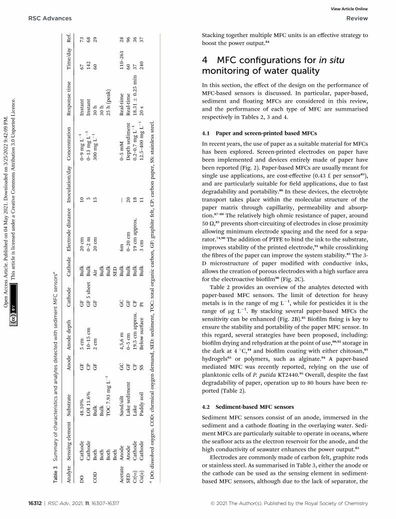
In this section, the effect of the design on the performance ofMFC-based sensors is discussed. In particular, paper-based,sediment and oating MFCs are considered in this review,and the performance of each type of MFC are summarisedrespectively in Tables 2, 3 and 4.
4.1 Paper and screen-printed based MFCs
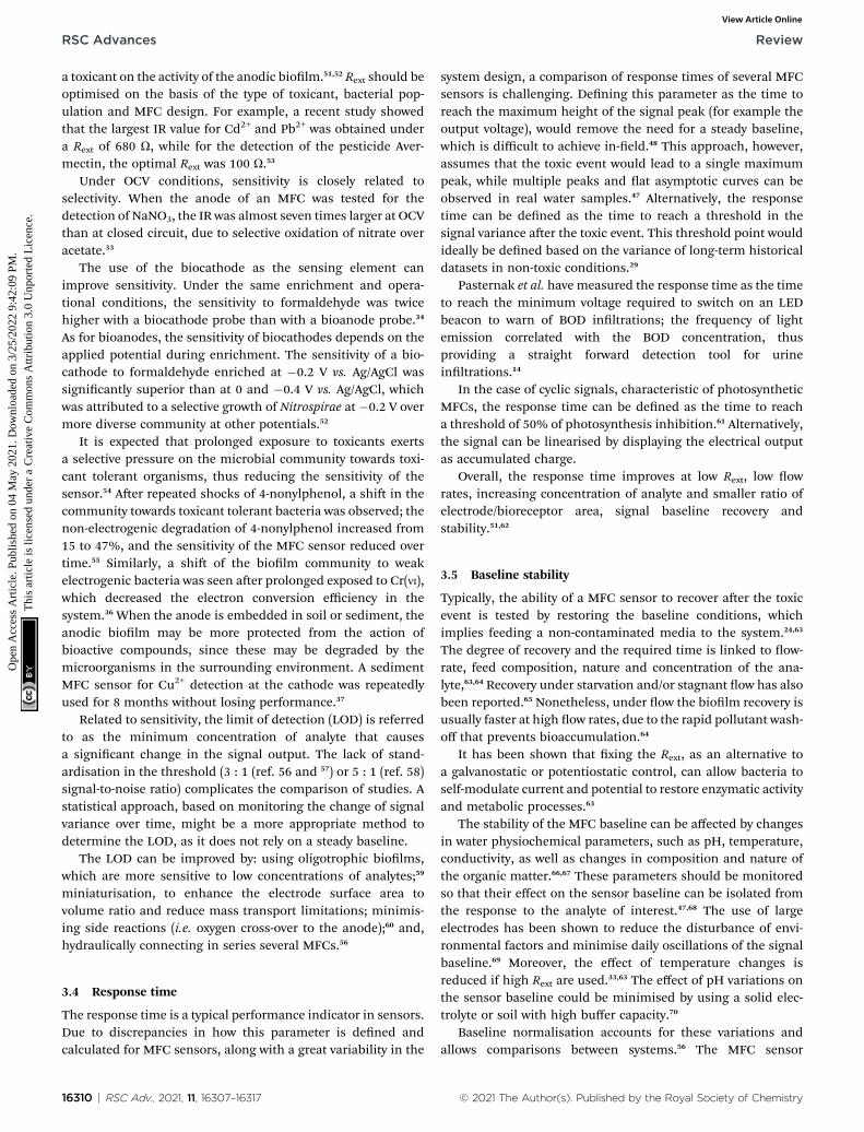
In recent years, the use of paper as a suitable material for MFCshas been explored. Screen-printed electrodes on paper havebeen implemented and devices entirely made of paper havebeen reported (Fig. 2). Paper-based MFCs are usually meant forsingle use applications, are cost-effective (0.43 £ per sensor85),and are particularly suitable for eld applications, due to fastdegradability and portability.86 In these devices, the electrolytetransport takes place within the molecular structure of thepaper matrix through capillarity, permeability and absorp-tion.87–89 The relatively high ohmic resistance of paper, around50 U,85 prevents short-circuiting of electrodes in close proximityallowing minimum electrode spacing and the need for a sepa-rator.74,90 The addition of PTFE to bind the ink to the substrate,improves stability of the printed electrode,91 while crosslinkingthe bres of the paper can improve the system stability.85 The 3-D microstructure of paper modied with conductive inks,allows the creation of porous electrodes with a high surface areafor the electroactive biolm90 (Fig. 2C).
Table 2 provides an overview of the analytes detected withpaper-based MFC sensors. The limit of detection for heavymetals is in the range of mg L�1, while for pesticides it is therange of mg L�1. By stacking several paper-based MFCs thesensitivity can be enhanced (Fig. 2B).85 Biolm xing is key toensure the stability and portability of the paper MFC sensor. Inthis regard, several strategies have been proposed, including:biolm drying and rehydration at the point of use,90,92 storage inthe dark at 4 �C,44 and biolm coating with either chitosan,85
hydrogels93 or polymers, such as alginate.94 A paper-basedmediated MFC was recently reported, relying on the use ofplanktonic cells of P. putida KT2440.95 Overall, despite the fastdegradability of paper, operation up to 80 hours have been re-ported (Table 2).
4.2 Sediment-based MFC sensors
Sediment MFC sensors consist of an anode, immersed in thesediment and a cathode oating in the overlaying water. Sedi-ment MFCs are particularly suitable to operate in oceans, wherethe seaoor acts as the electron reservoir for the anode, and thehigh conductivity of seawater enhances the power output.83
Electrodes are commonly made of carbon felt, graphite rodsor stainless steel. As summarised in Table 3, either the anode orthe cathode can be used as the sensing element in sediment-based MFC sensors, although due to the lack of separator, the
© 2021 The Author(s). Published by the Royal Society of Chemistry

Tab
le4
.Designch
arac
teristicsan
dperform
ance
offloatingMFC
biosenso
rsa
Analyte
Sensingelem
entDesign
Sepa
rator
Anod
eInoculum
Cathod
eStartup
/day
Sensitivity
LOD
mgL�
1Ope
ration
timeStack
Ref.
Urine
Anod
eTub
ular
Terracotta
CFV
AS
CFV
PTFE
50.02
1Hzmin
57.7
�4.8
5mon
ths
414
WWTP
Anod
eTub
ular
(smallbo
at)
Terracotta
CF
Den
itrication
tank
AC
15—
—3years
1669
Anod
eTubu
lar(big
boat)
Terracotta
CF
AC
15—
—32
Anod
eFlat
large
PPEfelt
CC
CC
30—
—1
Anod
eFlat
med
ium
PPEfelt
CC
CC
30—
—4
Anod
eFlat
small
PPEfelt
CC
CC
30—
—6
Cu
Anod
eFlat
NA
CF
Fieldmixed
MnO/C
—23
.5(LC50
)10
days
164
Oil
Cathod
eUpw
ardOpe
nch
annel
circular
NA
CC
WW
CC/Pt/Cteon
3h
32.11mVmL�
10.5mL
110
0Oxygen
Cathod
eSo
ilMFC
Terracotta
GF
Soil
CC
1553
.3�
22.6
mVLmg�
10mgL�
13mon
ths
172
aWWTP:
wastewater
treatm
entplan
t,PM
S:po
wer
man
agem
entsystem
,CFV
:carbo
nbreveil,P
PE:p
olyp
hen
ylen
eether,C
C:c
arbo
ncloth,A
C:a
ctivated
carbon
.
Fig. 2 Paper based MFC designs. (A) Membrane-based online stickerfor wastewater monitoring.86 (B) Screen printed biosensor for toxicitydetection in water.85(C) Paper MFC sensor with conductive reservoirfor bacterial attachment.90
Figactme
© 2021 The Author(s). Published by the Royal Society of Chemistry
Review RSC Advances
Ope
n A
cces
s A
rtic
le. P
ublis
hed
on 0
4 M
ay 2
021.
Dow
nloa
ded
on 3
/25/
2022
9:4
2:09
PM
. T
his
artic
le is
lice
nsed
und
er a
Cre
ativ
e C
omm
ons
Attr
ibut
ion
3.0
Unp
orte
d L
icen
ce.
View Article Online
toxicant diffuse to both electrodes, working as a dualbioreceptor.
A sediment MFC sensor was installed in boreholes tocontrol the supply of acetate for uranium biodegradation ingroundwater (Fig. 3A).28 Velasquez et al. tested four designsto monitor BOD, where the anode was either embedded insediment or oating on water.29 Repeated contaminationshocks with heavy metals, such as Cu2+, were monitored witha sediment MFC that used a cathode to sense, whereasexoelectrogenic bacteria, protected by soil, transformed Cu2+
to nontoxic fractions for long-term operations (Fig. 3B).37
In another study, the anode activity was used to detectexcessive accumulation of organic matter in sediments,a cause of oxygen depletion in water and greenhouse emis-sions.96 Seven horizontally and vertically spaced anodesprovided a prole of oxygen and availability of electrondonors in the sediment (Fig. 3C).96
. 3 Examples of sediment MFCs. (A). Monitoring of microbialivity for uranium remediation.28 (B) Detection of Cu2+;37 (C) sedi-nt bulking sensor.96
RSC Adv., 2021, 11, 16307–16317 | 16313

RSC Advances Review
Ope
n A
cces
s A
rtic
le. P
ublis
hed
on 0
4 M
ay 2
021.
Dow
nloa
ded
on 3
/25/
2022
9:4
2:09
PM
. T
his
artic
le is
lice
nsed
und
er a
Cre
ativ
e C
omm
ons
Attr
ibut
ion
3.0
Unp
orte
d L
icen
ce.
View Article Online
Sediment MFCs have also been used to detect eutrophica-tion68 and stratication,73 by monitoring dissolved oxygen inenvironmental waters. Stratication in a shallow lake wasdetected with a multi-cathode sediment MFC (Fig. 4A).73 Theoxygen reduction reaction at the cathode controlled the elec-trical output of the sensor, providing a prole of oxygen in thewater column. In another study, the signal of a sediment MFCoperating in a coastal bay (Fig. 4B), correlated directly with thevariations in temperature and dissolved oxygen, and indirectlywith tidal, irradiance, algal blooms and rainfall events.68 Unlikeother studies,29 here the ohmic drop, due to the distancebetween electrodes, did not affect the signal probably asa consequence of the high conductivity in seawater. As reportedin Table 3, the upper limit of DO detection in sediment MFCs isaround 5mg L�1, which is larger than theminimum 2mg L�1 ofdissolved oxygen required to sustain aquatic life.97 Sediment-based MFC sensors could therefore work as early warningsystems for hypoxic events.72 Sediment MFCs can also be usedas early warning tools for toxicity events, and in particular tomonitor the presence of oxidants at the cathode with higherpotential than oxygen, like Cr(VI).36
Additionally, plant MFCs have been recently proposed tomonitor rainfall98 and acid rain.99 In the latter case, the organicmatter produced by the plant Oryza sativa japonica, provideda sustainable source of electrons to the anode. When the plantwas exposed to acid rain, modelled as a mixture of HNO3 and
Fig. 4 Sediment MFCs for DO monitoring. (A) Monitoring of DO ina water column of a shallow lake with a sediment MFC with verticalcathode array;73 (B) multi-cathode SMFC deployed in an eutrophicbay.68
16314 | RSC Adv., 2021, 11, 16307–16317
H2SO4, a 77% drop in current was observed. The currentcorrelated with the change in the total organic carbon in theroots produced by the toxic event, suggesting fast transfer rateof the perturbation from leaves to roots. These remarkablendings imply that plant MFCs can be very effective as eldbiosensors to monitor toxic compounds affectingphotosynthesis.99
4.3 Floating MFC sensors
Floating MFCs are self-contained devices in which the anode issubmerged in water and the cathode is usually exposed to air.Floating MFC sensors have been reported for the monitoring ofBOD,69 urine,14 oil spills,100 toxic contamination64 and dissolvedoxygen72 in freshwater bodies.
In oating MFCs, a minimum electrode spacing can beachieved, which usually corresponds to the thickness of theseparator used in sandwiched-like congurations.64,72 None-theless, in these devices the anode can be exposed to oxygen,which affects the electrochemical performance of the sensorand the output signal. The use of highly porous101 or lamen-tous102 anodes, can limit this issue by allowing the developmentof dense colonies of bacteria onto the electrode surface thatconsume the oxygen on the bulk interface and create anaerobicareas at the electrode interface. Other proposed approaches toreduce the oxygen ux towards the anode include covering theanode with a thick porous polymeric64 or ceramic layer,72,82 orembedding the anode in soil.72,82
As summarised in Table 4, several oating MFC sensors havebeen successfully implemented in the eld. Light and soundbeacons were powered with a oating ceramic MFC in thepresence of urine (Fig. 5A).14 A oating MFC sensor enriched inoligotrophic bacteria was used to detect Cu in water with low
Fig. 5 Field biosensors based on floatingMFC; (A) detection of urine inwater with a beacon Early Warning System;14 (B) detection of metals inriver water;64 (C) sludge monitoring with floating boats (left) and flatfloating MFC (right);69(D) monitoring of oil spillages.100 (E) Dissolvedoxygen monitoring with ceramic soil MFCs.72
© 2021 The Author(s). Published by the Royal Society of Chemistry

Review RSC Advances
Ope
n A
cces
s A
rtic
le. P
ublis
hed
on 0
4 M
ay 2
021.
Dow
nloa
ded
on 3
/25/
2022
9:4
2:09
PM
. T
his
artic
le is
lice
nsed
und
er a
Cre
ativ
e C
omm
ons
Attr
ibut
ion
3.0
Unp
orte
d L
icen
ce.
View Article Online
organic content (Fig. 5B).64 Several low-cost, oating congu-rations using ceramic separators have been reported deployedto monitor BOD in the anoxic tank of a wastewater treatmentplant (Fig. 5C).69 Oil spills detection with a oating MFC, inwhich the cathode is used as the sensing element (Fig. 5D), hasalso been reported. In this case oxygen reduction at the cathoderelied on air diffusion into water, which was prevented when oilcovered the water surface.100
The oxygen reduction reaction at the cathode of soil basedoating MFC served as a proxy for early warning of hypoxia inwater bodies (Fig. 5E).72
5. Use of algorithms for data analysisand interpretation
Practical operations in eld of MFC sensors, require accountingfor any dri in the signal baseline using calibration models.Most models reported so far, however, have been developed byconsidering one factor affecting the MFC sensor signal at thetime, thus neglecting interferences between several factors inreal scenarios.36,103 The Design of Experiments is an effectivestatistical approach that identies the most inuential factorsand provides a calibration model where both the main effectsand their interactions are considered.72 Machine learning toolsprovide interesting algorithms to predict the signal in non-steady conditions. The use of Articial Neural Networks hasbeen suggested as a strategy to correlate geometrical signalfeatures of a MFC sensor with the type and concentration ofdifferent organic substrates and the presence of several toxi-cants in water.104
Algorithms to implement MFC sensors as decision makingtools are classied as baseline methods and signal processingmethods.105 In baseline methods, the averaged deviationbetween the observed and predicted responses is measured overtime and compared to a threshold. If the averaged deviation isgreater than the threshold value, an alarm is triggered. Adrawback of baseline detection methods is related to their poordifferentiation between noise and signal. Data driven methodscorrelate signals of sensors spatially distributed tominimise thenoise.106
6. Conclusions
MFC-based sensors have great potential as in-eld early detec-tion warning tools of water pollution, due to their robustness,simplicity in design and operation, cost-effectiveness andpotential autonomy. Performance indicators of in-eld appli-cations of this technology can inform on its reliability and therisk of false positive/negative alarms. The procedures to obtainthese indicators should be standardised to facilitate thecomparison of different studies.
Overall, the key challenges that must be addressed forpractical implementations of MFC sensors are to: decouple thesignal components in conditions of multiple disturbances, suchas BOD variations, environmental conditions and the presenceof a bioactive compound; provide a steady, passive supply or
© 2021 The Author(s). Published by the Royal Society of Chemistry
organic matter to the anode; stabilise the baseline with respectto environmental variations and/or develop calibration modelsthat account for any dri during operation.
The dependency of the anodic activity on the organic contentin the tested water could be reduced by using a solid anolyte toprovide a long-lasting, constant source of electron donor.
The applied external resistance has an important inuenceon several indicators. A xed Rext/Rint ratio to achieve optimalselectivity, sensitivity, response time and stability, could bemaintained by implementing a feedback-loop system thataccounts for variations in internal resistance over time.
Selectivity could be improved by integrating the MFC sensorwith a multisensory platform for pH, DO, temperature andconductivity monitoring, and by using sequential bioanode/biocathode as the sensing probes to generate a series of sepa-rated signals generated from each electrode.
Further research is needed to determine the recovery degreeof the bioreceptor, as well as its resistance, and consequentlythe sensor reliability, over multiple and repetitive toxic events.Should the damage be irreversible, an array of biolms coveredwith protective layers (i.e. alginate) of increasing thicknesses,that slowly dissolves in water, could act like a time series arrayof sacricial bioreceptors.
Regarding designs, paper MFCs are ideal for single usediagnostics, while oating MFCs are suitable for continuousmonitoring of water bodies. In particular, soil or plant-baseddesigns can provide a constant supply of organics to theanode for enhanced stability. Using a ceramic matrix couldimprove the lifetime and reusability of the sensor.
The use of a power management system can assist withautonomous functions and allow long-distance transmissionof the sensor readings. The long-term stability in-eld of thesesystems under environmental conditions, however, still needsto be investigated. Long-term data sets of MFC sensors oper-ating in eld are needed to improve the signal treatment anddecision algorithms to minimise the errors as early warningtools. Equally, a holistic approach to calibrate the sensor,involving a design of experiments, is recommended to accountfor the impact of variable environmental factors on the signaloutput. The calibration method should also account for vari-ations in the baseline, thus reducing the need for re-calibration.
Author contributions
LGO: writing – original dra preparation. MDL: Supervision,Writing – Review and editing.
Conflicts of interest
There are no conicts to declare.
Acknowledgements
This work was supported by the UK Engineering and PhysicalSciences Research Council (EP/L016214/1).
RSC Adv., 2021, 11, 16307–16317 | 16315
RSC Advances Review
Ope
n A
cces
s A
rtic
le. P
ublis
hed
on 0
4 M
ay 2
021.
Dow
nloa
ded
on 3
/25/
2022
9:4
2:09
PM
. T
his
artic
le is
lice
nsed
und
er a
Cre
ativ
e C
omm
ons
Attr
ibut
ion
3.0
Unp
orte
d L
icen
ce.
View Article Online
Notes and references
1 E. Boelee, G. Geerling, B. van der Zaan, A. Blauw andA. D. Vethaak, Acta Trop., 2019, 193, 217–226.
2 SDG 6 Synthesis Report 2018 on Water and Sanitation, 2018.3 UNICEF and WHO, Progress on household drinking water,sanitation and hygiene 2000–2017: Special focus oninequalities, 2019.
4 H. B. Glasgow, J. A. M. Burkholder, R. E. Reed, A. J. Lewitusand J. E. Kleinman, J. Exp. Mar. Biol. Ecol., 2004, 300, 409–448.
5 European Environmental Agency, Assessment of informationgaps in existing, Copenhagen, 2008.
6 Y. Wei, Y. Jiao, D. An, D. Li, W. Li and Q. Wei, Sensors, 2019,19, 3995.
7 S. N. Zulkii, H. A. Rahim and W. J. Lau, Sens. Actuators, B,2018, 255, 2657–2689.
8 S. D. Richardson and T. A. Ternes, Fundam. Appl. Rev. Anal.Chem., 2018, 90, 398–428.
9 S. H. A. Hassan, S. W. Van Ginkel, M. A. M. Hussein,R. Abskharon and S.-E. Oh, Environ. Int., 2016, 92–93,106–118.
10 F. Lagarde and N. Jaffrezic-renault, Anal. Bioanal. Chem.,2011, 400, 947–964.
11 L. Su, W. Jia, C. Hou and Y. Lei, Biosens. Bioelectron., 2011,26, 1788–1799.
12 Y. Cui, B. Lai and X. Tang, Biosensors, 2019, 9, 1–18.13 A. Prevoteau and K. Rabaey, ACS Sens., 2017, 2, 1072–1085.14 G. Pasternak, J. Greenman and I. Ieropoulos, Sens.
Actuators, B, 2017, 244, 815–822.15 R. W. Bradley, P. Bombelli, S. J. L. Rowden and C. J. Howe,
Biochem. Soc. Trans., 2012, 40, 1302–1307.16 D. Ucar, Y. Zhang and I. Angelidaki, Front. Microbiol., 2017,
8, 1–14.17 M. Di Lorenzo, T. P. Curtis, I. M. Head, S. B. Velasquez-Orta
and K. Scott, Water Sci. Technol., 2009, 60, 2879–2887.18 B. H. Kim, I. S. Chang, G. C. Gil, H. S. Park and H. J. Kim,
Biotechnol. Lett., 2003, 25, 541–545.19 Y. J. Shen, O. Lefebvre, Z. Tan and H. Y. Ng, Water Sci.
Technol., 2012, 65, 1223–1228.20 P. Kannan, P. Jogdeo, A. F. Mohidin, P. Y. Yung, C. Santoro,
T. Seviour, J. Hinks, F. M. Lauro and E. Marsili, Electrochim.Acta, 2019, 317, 604–611.
21 J. Hinks, E. J. Y. Han, V. B. Wang, T. W. Seviour, E. Marsili,J. S. C. Loo and S. Wuertz, Microb. Biotechnol., 2016, 9, 746–757.
22 Y. Shen, M. Wang, I. S. Chang and H. Y. Ng, Bioresour.Technol., 2013, 136, 707–710.
23 B. Liu, Y. Lei and B. Li, Biosens. Bioelectron., 2014, 62, 308–314.
24 M. Di Lorenzo, A. R. Thomson, K. Schneider, P. J. Cameronand I. Ieropoulos, Biosens. Bioelectron., 2014, 62, 182–188.
25 A. Khan, E. S. Salama, Z. Chen, H. Ni, S. Zhao, T. Zhou,Y. Pei, R. K. Sani, Z. Ling, P. Liu and X. Li, Biosens.Bioelectron., 2020, 147, 111763.
16316 | RSC Adv., 2021, 11, 16307–16317
26 J. Labro, T. Craig, S. A. Wood and M. A. Packer, Int. J.Nanotechnol., 2017, 14, 213.
27 A. ElMekawy, H. M. Hegab, D. Pant and C. P. Saint, J. Appl.Microbiol., 2018, 124, 302–313.
28 K. H. Williams, K. P. Nevin, A. Franks, A. Englert, P. E. Longand D. R. Lovley, Environ. Sci. Technol., 2010, 44, 47–54.
29 S. B. Velasquez-Orta, D. Werner, J. C. Varia and S. Mgana,Water Res., 2017, 117, 9–17.
30 T. Zhou, H. Han, P. Liu, J. Xiong, F. Tian and X. Li, Sensors,2017, 17, 2230.
31 Y. Jiang, P. Liang, P. Liu, Y. Bian, B. Miao, X. Sun, H. Zhangand X. Huang, Int. J. Mol. Sci., 2016, 17, 1392.
32 T. Tommasi, G. P. Salvador and M. Quaglio, Sci. Rep., 2016,6, 29091.
33 D. Wang, P. Liang, Y. Jiang, P. Liu, B. Miao, W. Hao andX. Huang, Biosens. Bioelectron., 2018, 111, 97–101.
34 Y. Jiang, P. Liang, P. Liu, D. Wang, B. Miao and X. Huang,Biosens. Bioelectron., 2017, 94, 344–350.
35 T. Zhao, B. Xie, Y. Yi and H. Liu, Bioresour. Technol., 2019,276, 276–280.
36 S. Zhao, P. Liu, Y. Niu, Z. Chen, A. Khan, P. Zhang and X. Li,Sensors, 2018, 18, 642.
37 L. Liu, Y. Lu, W. Zhong, L. Meng and H. Deng, Sci. TotalEnviron., 2020, 748, 1–9.
38 Y. Yi, B. Xie, T. Zhao, Z. Qian and H. Liu, Bioelectrochemistry,2019, 128, 109–117.
39 A. Prevoteau and K. Rabaey, ACS Sens., 2017, 2, 1072–1085.40 M. Estevez-Canales, A. Berna, Z. Borjas and A. Esteve-
Nunez, Energies, 2015, 8, 13211–13221.41 J. Kretzschmar, C. Koch, J. Liebetrau, M. Mertig and
F. Harnisch, Sens. Actuators, B, 2017, 241, 466–472.42 N. E. Stein, K. J. Keesman, H. V. M. Hamelers and G. van
Straten, Biosens. Bioelectron., 2011, 26, 3115–3120.43 H. T. Pham, AIMS Microbiol., 2018, 4, 567–583.44 M. Tucci, P. Bombelli, C. J. Howe, S. Vignolini, S. Bocchi
and A. Schievano, Microorganisms, 2019, 7, 1–14.45 I. B. Tahirbegi, J. Ehgartner, P. Sulzer, S. Zieger,
A. Kasjanow, M. Paradiso, M. Strobl, D. Bouwes andT. Mayr, Biosens. Bioelectron., 2017, 88, 188–195.
46 X. Qi, P. Liu, P. Liang, W. Hao, M. Li and X. Huang, Biosens.Bioelectron., 2019, 142, 111500.
47 Y. Feng, O. Kayode and W. F. Harper, Sci. Total Environ.,2013, 449, 223–228.
48 Y. Jiang, X. Yang, P. Liang, P. Liu and X. Huang, RenewableSustainable Energy Rev., 2018, 81, 292–305.
49 Z. Xu, Y. Liu, I. Williams, Y. Li, F. Qian, H. Zhang, D. Cai,L. Wang and B. Li, Biosens. Bioelectron., 2016, 85, 232–239.
50 V. Agostino, G. Massaglia, M. Gerosa, A. Sacco, G. Saracco,V. Margaria and M. Quaglio, New Biotechnol., 2020, 55, 36–45.
51 H. Moon, I. S. Chang, K. H. Kang, J. K. Jang and B. H. Kim,Biotechnol. Lett., 2004, 26, 1717–1721.
52 C. Liao, J. Wu, L. Zhou, T. Li, Q. Du, J. An, N. Li andX. Wang, Sci. Total Environ., 2018, 644, 1485–1492.
53 Y. Yi, B. Xie, T. Zhao, Z. Li, D. Stom and H. Liu,Bioelectrochemistry, 2019, 125, 71–78.
© 2021 The Author(s). Published by the Royal Society of Chemistry
Review RSC Advances
Ope
n A
cces
s A
rtic
le. P
ublis
hed
on 0
4 M
ay 2
021.
Dow
nloa
ded
on 3
/25/
2022
9:4
2:09
PM
. T
his
artic
le is
lice
nsed
und
er a
Cre
ativ
e C
omm
ons
Attr
ibut
ion
3.0
Unp
orte
d L
icen
ce.
View Article Online
54 A. Adekunle, V. Raghavan and B. Tartakovsky, Biosens.Bioelectron., 2019, 132, 382–390.
55 A. Godain, M. W. A. Spurr, H. C. Boghani, G. C. Premier,E. H. Yu and I. M. Head, Front. Environ. Sci. Eng. China,2020, 8, 1–15, DOI: 10.3389/fenvs.2020.00005.
56 M. W. A. Spurr, E. H. Yu, K. Scott and I. M. Head, Environ.Sci.: Water Res. Technol., 2020, 6, 612–621.
57 S. B. Quek, L. Cheng and R. Cord-Ruwisch,Water Res., 2015,77, 64–71.
58 S. B. Quek, L. Cheng and R. Cord-ruwisch,Water Res., 2015,77, 64–71.
59 K. Hyun Kang, J. Kyung Jang, T. Hai Pham, H. Moon, I. SeopChang and B. Hong Kim, Biotechnol. Lett., 2003, 25, 1357–1361.
60 L. Cheng, S. B. Quek and R. Cord-ruwisch, Biotechnol.Bioeng., 2014, 111, 2412–2420.
61 S. Morin, B. Chaumet and N. Mazzella, Front. Environ. Sci.Eng. China, 2018, 6, 1–9.
62 Y. Jiang, P. Liang, P. Liu, X. Yan, Y. Bian and X. Huang, Int.J. Hydrogen Energy, 2017, 42, 4342–4348.
63 N. E. Stein, H. V. M. Hamelers and C. N. J. Buisman, Sens.Actuators, B, 2012, 171–172, 816–821.
64 A. Adekunle, C. Rickwood and B. Tartakovsky, Environ.Monit. Assess., 2020, 192, 52.
65 L. Gonzalez Olias, P. J. Cameron and M. Di Lorenzo, Front.Energy Res., 2019, 7, 1–11.
66 G. Massaglia, V. Margaria, A. Sacco, T. Tommasi,S. Pentassuglia, D. Ahmed, R. Mo and C. Fabrizio, Appl.Energy, 2018, 230, 78–85.
67 N. E. Stein, H. V. M. Hamelers and C. N. J. Buisman,Bioelectrochemistry, 2010, 78, 87–91.
68 K. Kubota, T. Watanabe, H. Maki, G. Kanaya, H. Higashiand K. Syutsubo, Bioresour. Technol. Reports, 2019, 6, 39–45.
69 P. Cristiani, I. Gajda, J. Greenman, F. Pizza, P. Bonelli andI. Ieropoulos, Front. Energy Res., 2019, 7, 1–11.
70 H.-S. Lee, K. Lee, S.-S. Kim and S.-H. Ko, J. Ind. Eng. Chem.,2003, 9, 360–365.
71 Y. Jiang, P. Liang, P. Liu, X. Yan and Y. Bian, Int. J. HydrogenEnergy, 2016, 42, 4342–4348.
72 L. G. Olias, A. R. Otero, P. J. Cameron and M. Di Lorenzo,Electrochim. Acta, 2020, 362, 137108.
73 N. Song, Z. Yan, H. Xu, Z. Yao, C. Wang, M. Chen andZ. Zhao, Sci. Total Environ., 2019, 673, 272–280.
74 G. Choi, D. J. Hassett and S. Choi, Analyst, 2015, 140, 4277–4283.
75 A. J. McCormick, P. Bombelli, R. W. Bradley, R. Thorne,T. Wenzel and C. J. Howe, Energy Environ. Sci., 2015, 8,1092–1109.
76 Q. Chen, Y. Liu, G. Liu, Q. Yang, X. Shi, H. Gao, L. Su andQ. Li, ACM Trans. Embed. Comput. Syst., 2017, 17, 1–25.
77 J. Wineld, L. D. Chambers, J. Rossiter and I. Ieropoulos,Bioresour. Technol., 2013, 148, 480–486.
78 A. Adekunle, V. Raghavan and B. Tartakovsky, J. PowerSources, 2017, 356, 324–330.
© 2021 The Author(s). Published by the Royal Society of Chemistry
79 B. Neethu and M. M. Ghangrekar,Water Sci. Technol., 2017,76(12), 3269–3277.
80 A. Prevoteau, P. Clauwaert, F. M. Kerckhof and K. Rabaey,Biosens. Bioelectron., 2019, 132, 115–121.
81 M. Rimboud, A. Bergel and B. Erable, Bioelectrochemistry,2016, 110, 46–51.
82 A. Schievano, A. Colombo, M. Grattieri, S. P. Trasatti,A. Liberale, P. Tremolada, C. Pino and P. Cristiani, J.Power Sources, 2017, 340, 80–88.
83 F. Zhang, L. Tian and Z. He, J. Power Sources, 2011, 196,9568–9573.
84 S. Chen, S. A. Patil, R. K. Brown and U. Schroder, Appl.Energy, 2018, 233–234, 15–28.
85 J. Chouler, A. Cruz-Izquierdo, S. Rengaraj, J. L. Scott andM. Di Lorenzo, Biosens. Bioelectron., 2018, 102, 49–56.
86 Z. Xu, B. Liu, Q. Dong, Y. Lei, Y. Li, J. Ren, J. McCutcheonand B. Li, Bioresour. Technol., 2015, 197, 244–251.
87 J. Wineld, P. Milani, J. Greenman and I. Ieropoulos, ECSTrans., 2018, 85, 1193–1200.
88 C. Santoro, J. Wineld, P. Theodosiou and I. Ieropoulos,Bioresour. Technol. Reports, 2019, 7, 100297.
89 R. Veerubhotla, D. Das and D. Pradhan, Biosens.Bioelectron., 2017, 94, 464–470.
90 J. H. Cho, Y. Gao, J. Ryu and S. Choi, ACS Omega, 2020, 5,13940–13947.
91 I. Shitanda, S. Kato, Y. Hoshi, M. Itagaki and S. Tsujimura,Chem. Commun., 2013, 49, 11110–11112.
92 J. H. Cho, Y. Gao and S. Choi, Sensors, 2019, 19, 5452.93 M. Sawa, A. Fantuzzi, P. Bombelli, C. J. Howe, K. Hellgardt
and P. J. Nixon, Nat. Commun., 2017, 8, 1–10, DOI: 10.1038/s41467-017-01084-4.
94 I. Shitanda, K. Takada, Y. Sakai and T. Tatsuma, Anal. Chim.Acta, 2005, 530, 191–197.
95 M. J. Gonzalez-Pabon, E. Corton and F. Figueredo,Chemosphere, 2021, 265, 12910.
96 C. Wang and H. Jiang, Sci. Total Environ., 2019, 697, 134009.97 R. Vaquer-Sunyer and C. M. Duarte, Proc. Natl. Acad. Sci. U.
S. A., 2008, 105, 15452–15457.98 N. F. Tapia, C. Rojas, C. A. Bonilla and I. T. Vargas, Sensors,
2018, 18, 1–9.99 T. Li, X. Wang, Q. Zhou, C. Liao, L. Zhou, L. Wan, J. An,
Q. Du, N. Li and Z. J. Ren, ACS Sens., 2018, 3, 1424–1430.100 Z. Dai, Z. Xu, T. Wang, Y. Fan, Y. Liu, R. Yu, G. Zhu, X. Lu
and B. Li, Biosens. Bioelectron.: X, 2019, 1, 100014.101 X. A. Walter, J. Greenman and I. A. Ieropoulos, Algal Res.,
2013, 2, 183–187.102 T. Yamashita, N. Ookawa, M. Ishida and H. Kanamori, Nat.
Publ. Gr., 2016, 6, 38552.103 Y. Zhang and I. Angelidaki, Biosens. Bioelectron., 2012, 38,
189–194.104 S. T. King, M. Sylvander, M. Kheperu, L. Racz and
W. F. Harper, Sci. Total Environ., 2014, 497–498, 527–533.105 S. Liu, R. Li, K. Smith and H. Che,Water Res., 2016, 93, 222–
229.106 S. Liu, K. Smith and H. Che, Water Res., 2015, 80, 109–118.
RSC Adv., 2021, 11, 16307–16317 | 16317