Embed Size (px)
Citation preview

INTERNATIONAL RESEARCH JOURNAL OF ENGINEERING AND TECHNOLOGY (IRJET) E-ISSN: 2395 -0056
VOLUME: 04 ISSUE: 02 | FEB -2017 WWW.IRJET.NET P-ISSN: 2395-0072
© 2017, IRJET | Impact Factor value: 5.181 | ISO 9001:2008 Certified Journal | Page 527
Micro Structure analysis of TIG Welded SS 301 Alloy
K Sreedhar1,J Nithin Kumar2, K Jithendar Reddy3,
1,3Assistant Professor, Mechanical Department, GCET, Hyderabad, India 2Assoc. Professor, Mechanical Department, GCET, Hyderabad, India
------------------------------------------------------------***---------------------------------------------------------------------
Abstract: This work deals with micro structure analysis of TIG welding SS 301 plates of dimension 200*75*6 mm were taken, the. The input parameters are root gap, current, electrode diameter and gas flow rate. The main effects plots were plotted using Minitab software .the analysis is done with analysis software.
Keywords: TIG welding, SS, Hardness, root gap, S/N Ratio.
1. INTRODUCTION GTAW welding is an electric arc welding process, in
which the fusion energy is produced by an electric arc burning between the work piece and the tungsten electrode. During the welding process the electrode, the arc and the weld pool are protected against the damaging effects of the atmospheric air by an inert shielding gas. By means of a gas nozzle the shielding gas is lead to the welding zone where it replaces the atmospheric air. TIG welding differs from the other arc welding processes by the fact that the electrode is not consumed like the electrodes in other processes such as MIG/MAG and MM. Stainless steel is widely used in sheet metal fabrication, especially in automotive, chemical and rail coach manufacturing, mainly due to its excellent corrosion resistance and better strength to weight ratio. Stainless steel is a generic name covering a group of metallic alloys with chromium content in excess of 10.5 percent and a maximum carbon content of 1.2 percent (according to European Standard EN 10088) and often includes other elements, such as nickel and molybdenum. Due to formation of a passive layer, this is 1 to 2 nanometers thick; this metal exhibits excellent corrosion resistance. The passive layer is self-healing, and therefore chemical or mechanical damages to it re-passivity in oxidizing environments. Stainless steel has been widely used for rail vehicle body shell design for many years owing to its corrosion resistance, low life-cycle cost, and high strength-to weight ratio and fire resistance. 1.1 Working Principle of TIG Welding Operation
TIG is an arc welding process, as shown in Fig. Wherein coalescence is produced by heating the work piece with an electrical arc struck between a tungsten electrode and the job. The electrical discharge generates a plasma arc between the electrode tip and the work piece to be welded. It is an arc welding process wherein coalescence is produced by heating the job with an electrical arc struck between a tungsten electrode and the job. The arc is normally initialized by a
power source with a high frequency generator. This produces a small spark that provides the initial conducting path through the air for the low voltage welding current. The arc generates high-temperature of approximately 6100 C and melts the surface of base metal to form a molten pool. A welding gas (argon, helium, nitrogen etc) is used to avoid atmospheric contamination of the molten weld pool. The shielding gas displaces the air and avoids the contact of oxygen and the nitrogen with the molten metal or hot tungsten electrode. As the molten metal cools, coalescence occurs and the parts are joined. The resulting weld is smooth and requires minimum finish.
Figure 1 working principle of tig welding
2.EXPERIMENTAL PROCEDURE In this work, SS 301 alloy of dimension 200*75*6mm
was taken and the number of pieces were 18.Tig was performed the number of experiments were 9, the process parameters are Root gap, Current, Electrode and Gas flow rate
2.1 SS 301 chemical composition Carbon 0.0582% Chromium 16.0600% Iron 72.6000% Manganese 1.9300% Nickel 6.5600% Phosphorus 0.0649% Silicon 0.3670% Sulphur 0.005%
2.2 Common Applications of 301 Stainless Steel Aircraft structural parts Trailer bodies Architectural (roof drainage/door frames, etc.) Auto body trim and wheel covers Utensils and table wear Conveyor parts
INTERNATIONAL RESEARCH JOURNAL OF ENGINEERING AND TECHNOLOGY (IRJET) E-ISSN: 2395 -0056
VOLUME: 04 ISSUE: 02 | FEB -2017 WWW.IRJET.NET P-ISSN: 2395-0072
© 2017, IRJET | Impact Factor value: 5.181 | ISO 9001:2008 Certified Journal | Page 528
Table 2.1 experimental setup Experiment
Root gap (mm
Current (amperes)
Electrode Diameter(mm)
Gas flow (liters/minute)
1 1 100 1.6 2 2 1 150 2.5 4 3 1 170 3 5 4 2 100 2.5 5 5 2 150 3 2 6 2 170 1.6 4 7 2.5 100 3 4 8 2.5 150 1.6 5 9 2.5 170 2.5 2
3. EXPERIMENTAL SPECIMENS
Figure.3.1: Specimen to conduct experiments
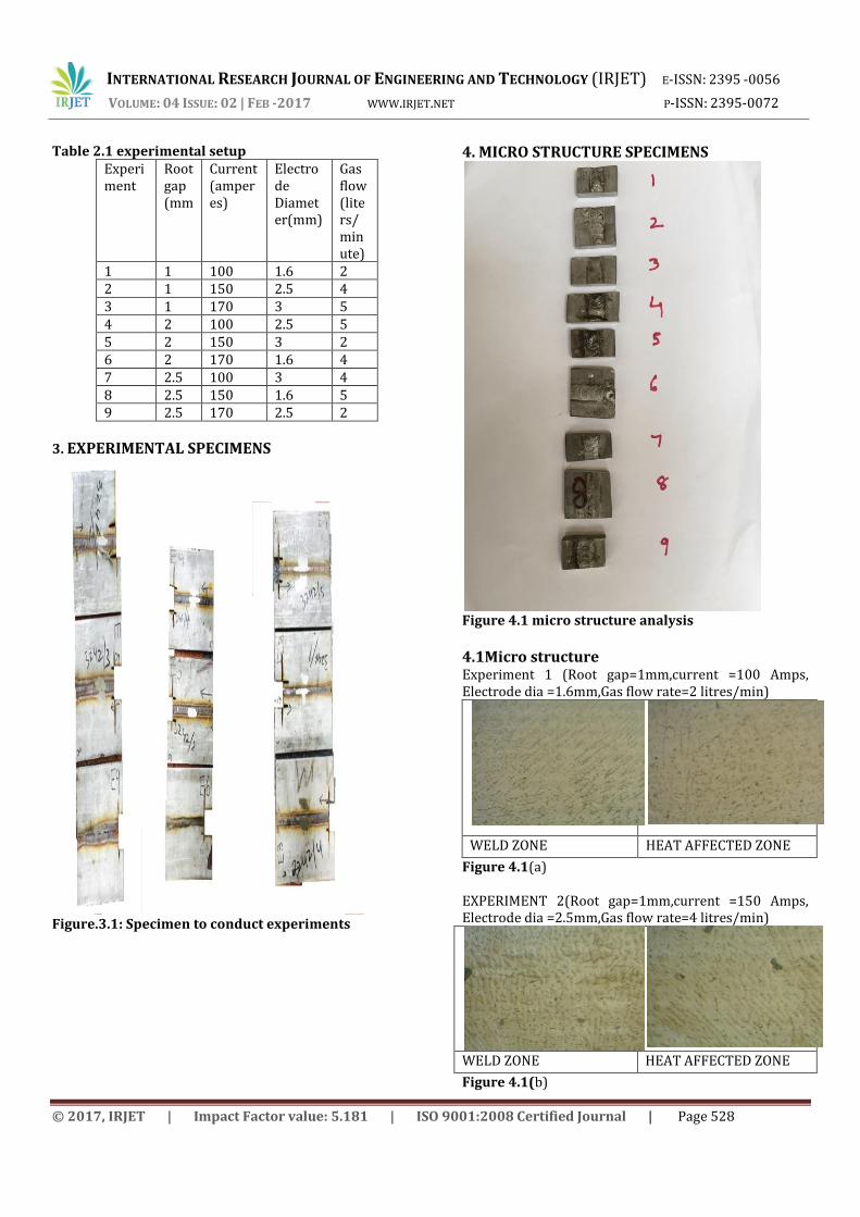
4. MICRO STRUCTURE SPECIMENS
Figure 4.1 micro structure analysis
4.1Micro structure Experiment 1 (Root gap=1mm,current =100 Amps, Electrode dia =1.6mm,Gas flow rate=2 litres/min)
WELD ZONE HEAT AFFECTED ZONE
Figure 4.1(a) EXPERIMENT 2(Root gap=1mm,current =150 Amps, Electrode dia =2.5mm,Gas flow rate=4 litres/min)
WELD ZONE HEAT AFFECTED ZONE
Figure 4.1(b)

INTERNATIONAL RESEARCH JOURNAL OF ENGINEERING AND TECHNOLOGY (IRJET) E-ISSN: 2395 -0056
VOLUME: 04 ISSUE: 02 | FEB -2017 WWW.IRJET.NET P-ISSN: 2395-0072
© 2017, IRJET | Impact Factor value: 5.181 | ISO 9001:2008 Certified Journal | Page 529
EXPERIMENT 3(Root gap=1mm,current =170 Amps, Electrode dia =3mm,Gas flow rate=5 litres/min)
WELD ZONE HEAT AFFECTED ZONE Figure 4.1(c) EXPERIMENT 4(Root gap=2mm,current =100 Amps, Electrode dia =2.5mm,Gas flow rate=5 litres/min)
WELD ZONE HEAT AFFECTED ZONE Figure 4.1(d) EXPERIMENT 5(Root gap=2mm,current =150 Amps, Electrode dia =3mm,Gas flow rate=2 litres/min)
WELD ZONE HEAT AFFECTED ZONE Figure 4.1(e) EXPERIMENT 6(Root gap=2mm,current =170 Amps, Electrode dia =1.6mm,Gas flow rate=4 litres/min)
WELD ZONE HEAT AFFECTED ZONE Figure 4.1(f)
EXPERIMENT 7(Root gap=2.5mm,current =100 Amps, Electrode dia =3 mm,Gas flow rate=4 litres/min)
WELD ZONE HEAT AFFECTED ZONE
Figure 4.1(g) EXPERIMENT 8(Root gap=2.5mm,current =150 Amps, Electrode dia =1.6 mm,Gas flow rate=5 litres/min)
WELD ZONE HEAT AFFECTED ZONE
Figure 4.1(h) EXPERIMENT 9(Root gap=2.5mm,current =170 Amps, Electrode dia =2.5 mm,Gas flow rate=2 litres/min)
WELD ZONE HEAT AFFECTED ZONE
Figure 4.1(i)
4.2 Software Analysis pictures of Micro structure Experiment 1
weld zone Austenite 25.09% Ferrite 77.36%
Heat affected zone Austenite 28.81% Ferrite 74.38%
Figure 4.2(a)
INTERNATIONAL RESEARCH JOURNAL OF ENGINEERING AND TECHNOLOGY (IRJET) E-ISSN: 2395 -0056
VOLUME: 04 ISSUE: 02 | FEB -2017 WWW.IRJET.NET P-ISSN: 2395-0072
© 2017, IRJET | Impact Factor value: 5.181 | ISO 9001:2008 Certified Journal | Page 530
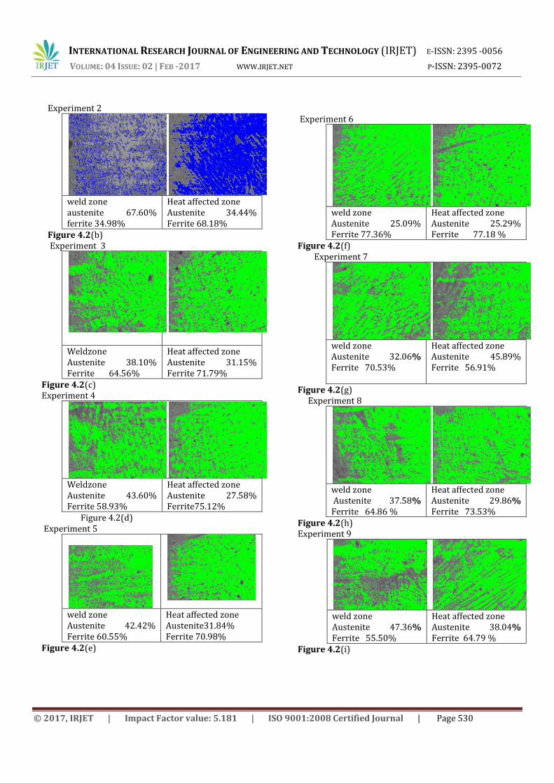
Experiment 2
weld zone austenite 67.60% ferrite 34.98%
Heat affected zone Austenite 34.44% Ferrite 68.18%
Figure 4.2(b) Experiment 3
Weldzone Austenite 38.10% Ferrite 64.56%
Heat affected zone Austenite 31.15% Ferrite 71.79%
Figure 4.2(c) Experiment 4
Weldzone Austenite 43.60% Ferrite 58.93%
Heat affected zone Austenite 27.58% Ferrite75.12%
Figure 4.2(d) Experiment 5
weld zone Austenite 42.42% Ferrite 60.55%
Heat affected zone Austenite31.84% Ferrite 70.98%
Figure 4.2(e)
Experiment 6
weld zone Austenite 25.09% Ferrite 77.36%
Heat affected zone Austenite 25.29% Ferrite 77.18 %
Figure 4.2(f) Experiment 7
weld zone Austenite 32.06% Ferrite 70.53%
Heat affected zone Austenite 45.89% Ferrite 56.91%
Figure 4.2(g) Experiment 8
weld zone Austenite 37.58% Ferrite 64.86 %
Heat affected zone Austenite 29.86% Ferrite 73.53%
Figure 4.2(h) Experiment 9
weld zone Austenite 47.36% Ferrite 55.50%
Heat affected zone Austenite 38.04% Ferrite 64.79 %
Figure 4.2(i)
INTERNATIONAL RESEARCH JOURNAL OF ENGINEERING AND TECHNOLOGY (IRJET) E-ISSN: 2395 -0056
VOLUME: 04 ISSUE: 02 | FEB -2017 WWW.IRJET.NET P-ISSN: 2395-0072
© 2017, IRJET | Impact Factor value: 5.181 | ISO 9001:2008 Certified Journal | Page 531
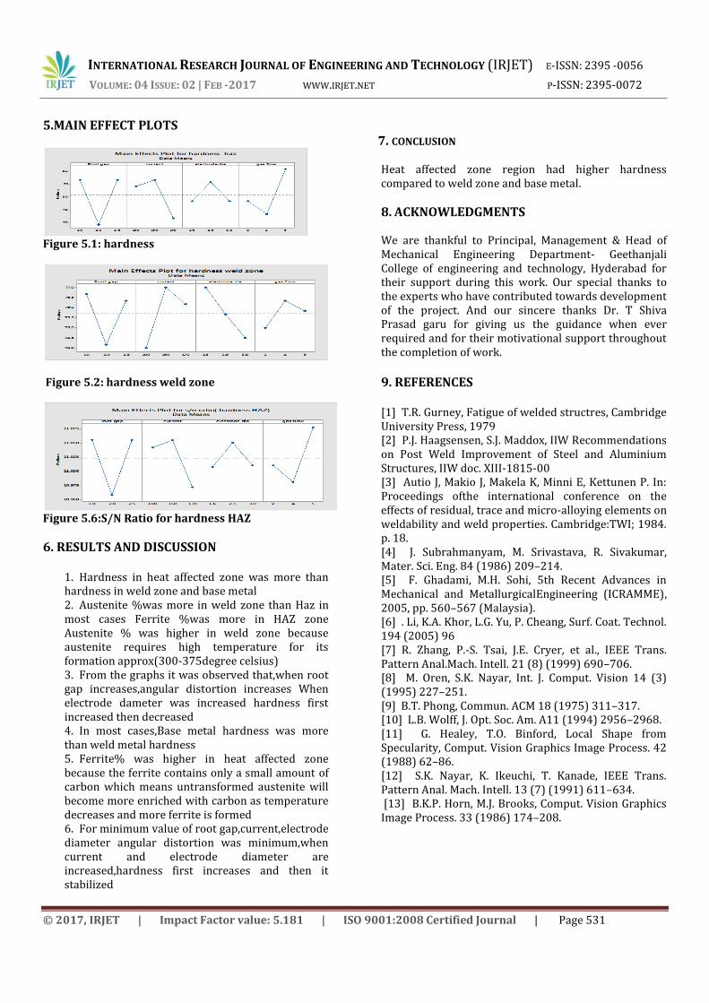
5.MAIN EFFECT PLOTS
Figure 5.1: hardness
Figure 5.2: hardness weld zone
Figure 5.6:S/N Ratio for hardness HAZ
6. RESULTS AND DISCUSSION
1. Hardness in heat affected zone was more than hardness in weld zone and base metal 2. Austenite %was more in weld zone than Haz in most cases Ferrite %was more in HAZ zone Austenite % was higher in weld zone because austenite requires high temperature for its formation approx(300-375degree celsius) 3. From the graphs it was observed that,when root gap increases,angular distortion increases When electrode dameter was increased hardness first increased then decreased 4. In most cases,Base metal hardness was more than weld metal hardness 5. Ferrite% was higher in heat affected zone because the ferrite contains only a small amount of carbon which means untransformed austenite will become more enriched with carbon as temperature decreases and more ferrite is formed 6. For minimum value of root gap,current,electrode diameter angular distortion was minimum,when current and electrode diameter are increased,hardness first increases and then it stabilized
7. CONCLUSION
Heat affected zone region had higher hardness compared to weld zone and base metal.
8. ACKNOWLEDGMENTS
We are thankful to Principal, Management & Head of Mechanical Engineering Department- Geethanjali College of engineering and technology, Hyderabad for their support during this work. Our special thanks to the experts who have contributed towards development of the project. And our sincere thanks Dr. T Shiva Prasad garu for giving us the guidance when ever required and for their motivational support throughout the completion of work.
9. REFERENCES [1] T.R. Gurney, Fatigue of welded structres, Cambridge University Press, 1979 [2] P.J. Haagsensen, S.J. Maddox, IIW Recommendations on Post Weld Improvement of Steel and Aluminium Structures, IIW doc. XIII-1815-00 [3] Autio J, Makio J, Makela K, Minni E, Kettunen P. In: Proceedings ofthe international conference on the effects of residual, trace and micro-alloying elements on weldability and weld properties. Cambridge:TWI; 1984. p. 18. [4] J. Subrahmanyam, M. Srivastava, R. Sivakumar, Mater. Sci. Eng. 84 (1986) 209–214. [5] F. Ghadami, M.H. Sohi, 5th Recent Advances in Mechanical and MetallurgicalEngineering (ICRAMME), 2005, pp. 560–567 (Malaysia). [6] . Li, K.A. Khor, L.G. Yu, P. Cheang, Surf. Coat. Technol. 194 (2005) 96 [7] R. Zhang, P.-S. Tsai, J.E. Cryer, et al., IEEE Trans. Pattern Anal.Mach. Intell. 21 (8) (1999) 690–706. [8] M. Oren, S.K. Nayar, Int. J. Comput. Vision 14 (3) (1995) 227–251. [9] B.T. Phong, Commun. ACM 18 (1975) 311–317. [10] L.B. Wolff, J. Opt. Soc. Am. A11 (1994) 2956–2968. [11] G. Healey, T.O. Binford, Local Shape from Specularity, Comput. Vision Graphics Image Process. 42 (1988) 62–86. [12] S.K. Nayar, K. Ikeuchi, T. Kanade, IEEE Trans. Pattern Anal. Mach. Intell. 13 (7) (1991) 611–634. [13] B.K.P. Horn, M.J. Brooks, Comput. Vision Graphics Image Process. 33 (1986) 174–208.

INTERNATIONAL RESEARCH JOURNAL OF ENGINEERING AND TECHNOLOGY (IRJET) E-ISSN: 2395 -0056
VOLUME: 04 ISSUE: 02 | FEB -2017 WWW.IRJET.NET P-ISSN: 2395-0072
© 2017, IRJET | Impact Factor value: 5.181 | ISO 9001:2008 Certified Journal | Page 532
BIOGRAPHIES Kasi Sreedhar received B.Tech
Mechanical degree from JNTUH in 2012. And M.Tech. Degree in Mechanical Engineering from JNTUH, Hyderabad in 2015, with specialization in Advanced manufacturing systems. Presently working as an Assistant professor in Geethanjali college of engineering and technology, Hyderabad.
J Nithin Kumar received B.Tech in Mechanical Engineering from JNTUH in 2009 and M.tech in advanced manufacturing systems from JNTUH in 2014. Having industrial experience of 3 years and teaching experience of 4 years. Presently working as an Assistant Professor in mechanical department at Geethanjali College of Engineering and Technology, Hyderabad.
K.Jithendar Reddy received B.Tech (Mechanical) Degree from KITS Warangal in 1993. And M Tech Degree in Industrial Metallurgy from NIT Warangal in 1995. Having 6 years of industry experience and 15 years of teaching experience. Presently working as Associate Professor in Mechanical Engineering Department at Geethanjali college of Engineering and technology, Hyderabad.
.