Embed Size (px)
Citation preview

Installation InstructionsP/N MMI-20010163, Rev. AJune 2007
ATEX Installation Instructions for Micro Motion® ELITE® Sensors with Certificate DMT 01 ATEX E 140 X
For ATEX-approved sensor installations

Information affixed to equipment that complies with the Pressure Equipment Directive can be found on the internet at www.micromotion.com/library.
©2007, Micro Motion, Inc. All rights reserved. ELITE and ProLink are registered trademarks, and MVD and MVD Direct Connect are trademarks of Micro Motion, Inc., Boulder, Colorado. Micro Motion is a registered trade name of Micro Motion, Inc., Boulder, Colorado. The Micro Motion and Emerson logos are trademarks and service marks of Emerson Electric Co. All other trademarks are property of their respective owners.
Note: For hazardous installations in Europe, refer to standard EN 60079-14 if national standards do not apply.

1
ELITE Sensors (DMT 01 ATEX E 140 X)ATEX Installation Instructions
• For installing the following Micro Motion sensors with ATEX Certificate number DMT 01 ATEX E 140 X:
- Model CMF010
- Model CMF025
- Model CMF050
- Model CMF100
- Model CMF200 (including high-temperature Model CMF200A)
- Model CMF300 (including high-temperature Model CMF300A)
Subject: Equipment type Sensor type CMF*** *******Z****
Manufactured and submitted for examination
Micro Motion, Inc.
Address Boulder, Co. 80301, USA
Basis for examination: Annex II of Directive 94/9/EC
Standard basis EN 50014:1997 +A1-A2 General requirements
EN 50020:2002 Intrinsic safety ´i´
EN 50281-1-1:1998 +A1 Dust evaluation ´D´
Code for type of protection EEx ib IIB/IIC T1–T6
ATEX Installation Instructions

ELITE Sensors (DMT 01 ATEX E 140 X)
2 ATEX Installation Instructions
1) Subject and type
Sensor type CMF*** *******Z****
Instead of the *** letters and numerals will be inserted which characterize the following modifications:
Marking without influence to the type of protection
Letter for electronics interface
2 = Aluminum enhanced core processor3 = Stainless steel enhanced core processor 4 = Extended aluminum enhanced core processor5 = Extended stainless steel enhanced core
processor6 = Aluminum enhanced core processor for direct
host7 = Stainless steel enhanced core processor for direct
host8 = Extended aluminum enhanced core processor for
direct host9 = Extended stainless steel enhanced core
processor for direct hostA = Local core processor B = Extended local core processorC = Integral 1700/2700D = Local core processor for direct hostE = Extended local core processor for direct hostF = Integral extended 1700/2700H = 9-wire extended junction boxQ = Aluminum core processorR = 9-wire junction boxS = 9-wire stainless steel junction boxV = Extended aluminum core processorW = Aluminum core processor for direct hostY = Extended aluminum core processor for direct host
C M F * * * * * * * * * Z * * * *
Marking without influence to the type of protection
Letter for conduit connections
*
3 numerals for type of sensor

ELITE Sensors (DMT 01 ATEX E 140 X)
ATEX Installation Instructions 3
2) Description
The flow sensor in combination with a transmitter is used for flow measurement.
The flow sensor, which consists of magnetically excited oscillating tubes, contains as electrical components coils, resistors, temperature sensors and terminals and connectors.
Instead of the junction box (CMF********(R, H or S)*Z****) an enclosure with an inside mounted signal processing device type 700 can be used; this variation gets the denomination type CMF*** *****(A, B, D or E)*Z****. For a SS enclosure and CMF*** ***** (Q, V, W or Y) *Z **** for an aluminum enclosure.
When used with an integral mounted enhanced signal processing device type 800; the variation gets the denomination type CMF*** *****(3, 5, 7 or 9)*Z**** for a SS enclosure and CMF*** *****(2, 4, 6 or 8)*Z**** for an aluminum enclosure.
Alternatively a transmitter type *700********** can be mounted directly to the junction box; this variation gets the denomination type CMF*** *****(C or F)*Z****.
The high temperature version CMF***A******Z**** can be executed with a junction box, transmitter, core processor, or enhanced core processor; this variation has therefore always the denomination CMF***A******Z****.
By mounting the sensor directly to the *700 transmitter the use of the unit will be modified according to the following table:
Sensor
CMF010*****(C or F)*Z****CMF025*****(C or F)*Z****CMF050*****(C or F)*Z****CMF100*****(C or F)*Z****
with CIC A2CMF200*****(C or F)*Z****
with CIC A4CMF300*****(C or F)*Z****
with CIC A4
CMF200*****(C or F)*Z**** with CIC A2, A3
CMF300*****(C or F)*Z**** with CIC A2, A3
CMF200A*****(C or F)*Z**** with CIC no marking
CMF300A*****(C or F)*Z**** with CIC A5
Transmitter type*700*1(1 or 2)******* 0575 II 2 G EEx ib IIB+H2 T1–T5 0575 II 2 G EEx ib IIB T1–T5
II 2 D IP65 T1 °C
(1) For dust temperature ratings, see temperature graphs.
II 2 D IP65 T1 °C
Transmitter type *700*1(3, 4 or 5)******* 0575 II 2 G EEx ib IIC T1–T5 0575 II 2 G EEx ib IIB T1–T5
II 2 D IP65 T1 °C II 2 D IP65 T1 °C
Transmitter type*700*1(1 or 2)D****** 0575 II 2 (1) G EEx ib IIB+H2 T1–T5 0575 II 2 (1) G EEx ib IIB T1–T5
II 2 D IP65 T1 °C II 2 D IP65 T1 °C
Transmitter type*700*1(3, 4, or 5)D****** 0575 II 2 (1) G EEx ib IIC T1–T5 0575 II 2 (1) G EEx ib IIB T1–T5
II 2 D IP65 T1 °C II 2 D IP65 T1 °C
Transmitter type2700*1(1 or 2)(E or G)****** 0575 II 2 (1) G EEx ib IIB+H2 T1–T5 0575 II 2 (1) G EEx ib IIB T1–T5
II 2 D IP65 T1 °C II 2 D IP65 T1 °C
Transmitter type2700*1(3, 4, or 5)(E or G)****** 0575 II 2 (1) G EEx ib IIC T1–T5 0575 II 2 (1) G EEx ib IIB T1–T5
II 2 D IP65 T1 °C II 2 D IP65 T1 °C

ELITE Sensors (DMT 01 ATEX E 140 X)
4 ATEX Installation Instructions
Amendment No. 3 to the ATEX Certificate DMT 01 ATEX E 140 X reflects the revised Drive Coil parameters for CMF 100, CMF 200, and CMF 300 for compatibility with other ATEX certified transmitters. Sensors constructed using these revised coil parameters will be identified with a Construction Identification Code (C.I.C.) of A2.
Amendment No. 6 to the ATEX Certificate DMT 01 ATEX E 140 X reflects the revised CMF200 and CMF300 Drive Coil and Pick-Off Coil parameters for improved performance. Sensors constructed using these revised coil parameters will be identified with a Construction Identification Code (C.I.C.) of A3.
Amendment No. 8 to the ATEX Certificate DMT 01 ATEX E 140 X reflects the addition of the Enhanced Core Processor Interface Codes (2-9) and the addition of the CMF200A model. Furthermore the addition of revised drive coil series resistance for the CMF200 and CMF300 sensors used at low temperature and IIC applications these are identified with a Construction Identification Code (C.I.C.) of A4. The revised coil parameters for the CMF300A are identified with a Construction Identification Code (C.I.C.) of A5.
3) Parameters
3.1) Type CMF********(R, H, or S)*Z**** (except CMF***A****(R, H or S)*Z****)
Construction Identification Code (C.I.C.) A2, A3, A4 (IIC) and no marking
3.1.1) Drive circuit
Power 2,54 W
Voltage 11,4 VDC
Current 2,45 A
Effective internal capacitance Negligible
Construction Identification Code (CIC)(Shown approximately where stamped)

ELITE Sensors (DMT 01 ATEX E 140 X)
ATEX Installation Instructions 5
Effective internal max. LI , min. coil & series resistor & min. ambient/fluid temp.
3.1.2) Pick-off circuit (terminals 5,9 and 6,8; green/white and blue/grey wires)
Effective internal max. LI , min. coil & series resistor & min. ambient/fluid temp.
CMF010 2,51 mH 86,8 Ω 946,6 Ω –20 °C
CMF025 2,51 mH 86,8 Ω 170,4 Ω –20 °C
CMF050 2,51 mH 86,8 Ω 170,4 Ω –20 °C
CMF100CIC A2
6,7 mH 64,5 Ω 89 Ω –20 °C
CMF200CIC A2
10,4 mH 65,7 Ω 24,7 Ω –20 °C
CMF200CIC A3
9,5 mH 102,6 Ω 0 Ω –20 °C
CMF200CIC A4 (IIC)
9,5 mH 0 Ω 177 Ω –240 °C
CMF300CIC A2
9,0 mH 74,8 Ω 5,9 Ω –20 °C
CMF300CIC A3
9,5 mH 102,6 Ω 0 Ω –20 °C
CMF300CIC A4 (IIC)
9,5 mH 0 Ω 177 Ω –240 °C
Voltage Up to 30 VDC
Current Up to 101 mA
Power Up to 750 mW
Effective internal capacitance Negligible
CMF010 2,51 mH 86,8 Ω 0 Ω –20 °C
CMF025 2,51 mH 86,8 Ω 0 Ω –20 °C
CMF050 2,51 mH 86,8 Ω 0 Ω –20 °C
CMF100CIC A2
0,441 mH 12,2 Ω 0 Ω –20 °C
CMF200CIC A2
0,61 mH 19,6 Ω 0 Ω –20 °C
CMF200CIC A3
2,0 mH 46,3 Ω 0 to 567,9 Ω –20 °C
CMF200CIC A4 (IIC)
2,0 mH 0 Ω 0 to 567,9 Ω –240 °C
CMF300CIC A2
0,61 mH 19,6 Ω 0 Ω –20 °C
CMF300CIC A3
2,0 mH 46,3 Ω 0 to 567,9 Ω –20 °C
CMF300CIC A4 (IIC)
2,0 mH 0 Ω 0 to 567,9 Ω –240 °C

ELITE Sensors (DMT 01 ATEX E 140 X)
6 ATEX Installation Instructions
3.1.3) Temperature circuit
3.1.4) Temperature class
The classification into a temperature class depends on the temperature of the medium taking into account the maximum operating temperature of the sensor and is shown in the following graphs:
For Construction Identification Code (C.I.C.) A2 and no marking
Note 1. Use the above graph to determine the temperature class for a given fluid and ambient temperature. The maximum surface temperature for dust is as follows: T6:T 80°C, T5:T 95°C, T4:T 130°C, T3:T 195°C, T2 to T1:T 245°C.
Voltage Up to 30 VDC
Current Up to 101 mA
Power Up to 750 mW
Effective internal capacitance Negligible
Effective internal inductance Negligible
ATEX ALLOWABLE CMF SENSOR TEMPERATURE RATING WITH INTEGRAL J-BOX BASED ON AMBIENT/FLUID TEMPERATURE
MA
X. A
MB
IEN
T T
EM
P. (
°C)
SENSOR FLUID TEMP. (°C)

ELITE Sensors (DMT 01 ATEX E 140 X)
ATEX Installation Instructions 7
For Construction Identification Code (C.I.C.) A3
Note 1. Use the above graph to determine the temperature class for a given fluid and ambient temperature. The maximum surface temperature for dust is as follows: T6:T 80°C, T5:T 95°C, T4:T 130°C, T3:T 195°C, T2 to T1:T 250°C.
3.1.5) Ambient temperature range
The use of the sensor at an ambient temperature higher than +55 °C is possible, provided that the ambient temperature does not exceed the maximum temperature of the medium taking into account the temperature classification and the maximum operating temperature of the sensor. Minimum medium temperature is –20 °C.
The ambient temperature of the sensor may be less than –20 °C provided the temperature of the medium is not less than 0 °C.
CMF********(R, H, or S)*Z**** (except CMF***A****(R, H or S)*Z****)
with CIC A2, A3, and no marking
Ta –20 °C up to +55 °C
ATEX ALLOWABLE CMF SENSOR TEMPERATURE RATING WITH INTEGRAL J-BOX BASED ON AMBIENT/FLUID TEMPERATURE
MA
X. A
MB
IEN
T T
EM
P. (
°C)
SENSOR FLUID TEMP. (°C)

ELITE Sensors (DMT 01 ATEX E 140 X)
8 ATEX Installation Instructions
3.1.6) Temperature class for Construction Identification Code (C.I.C.) A4 (IIC)
The classification into a temperature class depends on the temperature of the medium taking into account the maximum operating temperature of the sensor and is shown in the following graph:
Note 1. Use the above graph to determine the temperature class for a given fluid and ambient temperature. The maximum surface temperature for dust is as follows: T6:T 80°C, T5:T 95°C, T4:T 130°C, T3:T 195°C, T2 to T1:T 250°C. The minimum ambient and process fluid temperature allowed for dust is -40°C.
3.1.7) Ambient temperature range
The use of the sensor at an ambient temperature higher than +55 °C is possible, provided that the ambient temperature does not exceed the maximum temperature of the medium taking into account the temperature classification and the maximum operating temperature of the sensor.
CMF********(R, H, or S)*Z**** (except CMF***A****(R, H or S)*Z****)
with CIC A4
Ta –240 °C up to +55 °C
MA
X. A
MB
IEN
T T
EM
P (
°C)
SENSOR FLUID TEMP (°C)

ELITE Sensors (DMT 01 ATEX E 140 X)
ATEX Installation Instructions 9
3.2) Type CMF***A****(R, H or S)*Z****
Construction Identification Code (C.I.C.) A5 and no marking
3.2.1) Drive circuit
Effective internal max. LI , min. coil & series resistor & min. ambient/fluid temp.
3.2.2) Pick-off circuit
Effective internal max. LI , min. coil & series resistor & min. ambient/fluid temp.
3.2.3) Temperature circuit
Power 2,54 W
Voltage 11,4 VDC
Current 2,45 A
Effective internal capacitance Negligible
CMF200A 4,0 mH 34,0 Ω 19,8 Ω –40 °C
CMF300A 8,5 mH 63,2 Ω 31,3 Ω –20 °C
CMF300A CIC A5 4,0 mH 34,0 Ω 19,8 Ω –40 °C
Voltage Up to 30 VDC
Current Up to 101 mA
Power Up to 750 mW
Effective internal capacitance Negligible
CMF200A 1,25 mH 16,2 Ω 569,3 Ω –40 °C
CMF300A 0,393 mH 7,3 Ω 31,3 Ω –20 °C
CMF300A CIC A5 1,25 mH 16,2 Ω 569,3 Ω –40 °C
Voltage Up to 30 VDC
Current Up to 101 mA
Power Up to 750 mW
Effective internal capacitance Negligible
Effective internal inductance Negligible

ELITE Sensors (DMT 01 ATEX E 140 X)
10 ATEX Installation Instructions
3.2.4) Temperature class
The classification into a temperature class depends on the temperature of the medium taking into account the maximum operating temperature of the sensor and is shown in the following graphs:
For CMF300A Sensors with Construction Identification Code (C.I.C.) with no marking
Note 1. Use the above graph to determine the temperature class for a given fluid and ambient temperature. The maximum surface temperature for dust is as follows: T6:T 80°C, T5:T 95°C, T4:T 130°C, T3:T 195°C, T2:T 290°C, T1:T 365°C.
3.2.5) Ambient temperature range
The use of the sensor at an ambient temperature higher than +55 °C is possible, provided that the ambient temperature does not exceed the maximum temperature of the medium taking into account the temperature classification and the maximum operating temperature of the sensor. Minimum medium temperature is –20 °C.
The ambient temperature of the sensor may be less than –20 °C provided the temperature of the medium is not less than 0 °C.
CMF300A****(R, H or S)*Z**** with CIC no marking
Ta –20 °C up to +55 °C
MA
X. A
MB
IEN
T T
EM
P (
°C)
SENSOR FLUID TEMP (°C)
ATEX ALLOWABLE CMF300A SENSOR TEMPERATURE RATING WITH REMOTE J-BOX BASED ON AMBIENT/FLUID TEMPERATURE

ELITE Sensors (DMT 01 ATEX E 140 X)
ATEX Installation Instructions 11
3.2.6) Temperature class
The classification into a temperature class depends on the temperature of the medium taking into account the maximum operating temperature of the sensor and is shown in the following graphs:
For CMF200A and CMF300A (C.I.C. A5) Sensors with Integral J-Box
Note 1. Use the above graph to determine the temperature class for a given fluid and ambient temperature. The maximum surface temperature for dust is as follows: T6:T 80°C, T5:T 95°C, T4:T 130°C, T3:T 195°C, T2:T 290°C, T1:T 440°C.
3.2.7) Ambient temperature range
The use of the sensor at an ambient temperature higher than +55 °C is possible, provided that the ambient temperature does not exceed the maximum temperature of the medium taking into account the temperature classification and the maximum operating temperature of the sensor. Minimum medium temperature is –40 °C.
3.3) Type CMF********(2–9, A, B, D, E, Q, V, W or Y) *Z**** (except CMF***A****(2 – 9, A, B, D, E, Q, V, W or Y)*Z****)Construction Identification Code (C.I.C.) A2, A3, A4 (IIC) and no marking
3.3.1) Input circuits (terminals 1–4)
CMF200A****(R, H or S)*Z**** or CMF300A****(R, H, or S)*Z****
with CIC A5
Ta –40 °C up to +55 °C
Voltage Up to 17,3 VDC
Current Up to 484 mA
Power Up to 2,1 W
Effective internal capacitance 2200 pF
Effective internal inductance 30 μH
MA
X. A
MB
IEN
T T
EM
P (
°C)
SENSOR FLUID TEMP (°C)

ELITE Sensors (DMT 01 ATEX E 140 X)
12 ATEX Installation Instructions
3.3.2) Temperature class
The classification into a temperature class depends on the temperature of the medium taking into account the maximum operating temperature of the sensor and is shown in the following graphs: For Construction Identification Code (C.I.C.) A2 and no marking
Note 1. Use the above graph to determine the temperature class for a given fluid and ambient temperature. The maximum surface temperature for dust is as follows: T5:T 95°C, T4:T 130°C, T3:T 195°C, T2 to T1:T 245°C.
For Construction Identification Code (C.I.C.) A3
Note 1. Use the above graph to determine the temperature class for a given fluid and ambient temperature. The maximum surface temperature for dust is as follows: T5:T 95°C, T4:T 130°C, T3:T 195°C, T2 to T1:T 250°C.
ATEX ALLOWABLE CMF SENSOR TEMPERATURE RATING WITH INTEGRAL CORE BASED ON AMBIENT/FLUID TEMPERATURE
MA
X. A
MB
IEN
T T
EM
P. (
°C)
SENSOR FLUID TEMP. (°C)
De-rate at –0,093 °Cambient per °C fluid
ATEX ALLOWABLE CMF SENSOR TEMPERATURE RATING WITH INTEGRAL CORE BASED ON AMBIENT/FLUID TEMPERATURE
MA
X. A
MB
IEN
T T
EM
P. (
°C)
SENSOR FLUID TEMP. (°C)
De-rate at –0,093 °Cambient per °C fluid
ELITE Sensors (DMT 01 ATEX E 140 X)
ATEX Installation Instructions 13
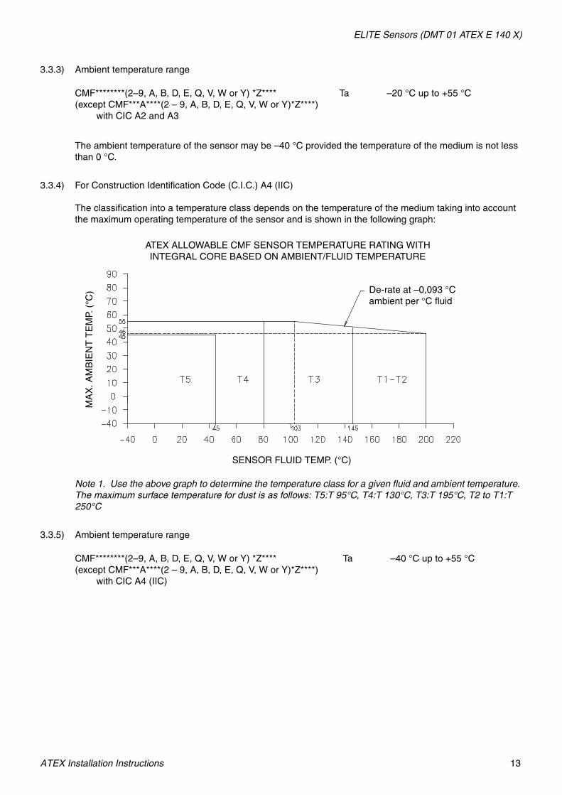
3.3.3) Ambient temperature range
The ambient temperature of the sensor may be –40 °C provided the temperature of the medium is not less than 0 °C.
3.3.4) For Construction Identification Code (C.I.C.) A4 (IIC)
The classification into a temperature class depends on the temperature of the medium taking into account the maximum operating temperature of the sensor and is shown in the following graph:
Note 1. Use the above graph to determine the temperature class for a given fluid and ambient temperature. The maximum surface temperature for dust is as follows: T5:T 95°C, T4:T 130°C, T3:T 195°C, T2 to T1:T 250°C
3.3.5) Ambient temperature range
CMF********(2–9, A, B, D, E, Q, V, W or Y) *Z**** (except CMF***A****(2 – 9, A, B, D, E, Q, V, W or Y)*Z****)
with CIC A2 and A3
Ta –20 °C up to +55 °C
CMF********(2–9, A, B, D, E, Q, V, W or Y) *Z**** (except CMF***A****(2 – 9, A, B, D, E, Q, V, W or Y)*Z****)
with CIC A4 (IIC)
Ta –40 °C up to +55 °C
ATEX ALLOWABLE CMF SENSOR TEMPERATURE RATING WITH INTEGRAL CORE BASED ON AMBIENT/FLUID TEMPERATURE
MA
X. A
MB
IEN
T T
EM
P. (
°C)
SENSOR FLUID TEMP. (°C)
De-rate at –0,093 °Cambient per °C fluid

ELITE Sensors (DMT 01 ATEX E 140 X)
14 ATEX Installation Instructions
3.4) Type CMF***A****(2–9, A, B, D, E, Q, V, W or Y)*Z****
CMF300A with Construction Identification Code (C.I.C.) A5CMF200A with Construction Identification Code (C.I.C.) no marking
3.4.1) Input circuits (terminals 1–4)
3.4.2) Temperature class
The classification into a temperature class depends on the temperature of the medium taking into account the maximum operating temperature of the sensor and is shown in the following graphs:
Note 1. Use the above graph to determine the temperature class for a given fluid and ambient temperature. The maximum surface temperature for dust is as follows: T5:T 95°C, T4:T 130°C, T3:T 195°C, T2: T 290°C, T1:T 440°C.
Voltage Up to 17,3 VDC
Current Up to 484 mA
Power Up to 2,1 W
Effective internal capacitance 2200 pF
Effective internal inductance 30 μH
MA
X. A
MB
IEN
T T
EM
P (
°C)
SENSOR FLUID TEMP (°C)

ELITE Sensors (DMT 01 ATEX E 140 X)
ATEX Installation Instructions 15
3.4.3) Ambient temperature range
Since the electronics are mounted approx. 1 meter away from the sensor by means of a flexible stainless steel hose, the use of the sensor at an ambient temperature higher than +55 °C is possible, provided that the ambient temperature does not exceed the maximum temperature of the medium taking into account the temperature classification and the maximum operating temperature of the sensor. Minimum medium temperature is –40 °C.
3.5) Type CMF********(C or F)*Z**** (except CMF***A****(C or F)*Z****)
Construction Identification Code (C.I.C.) A2, A3, A4 and no marking
3.5.1) Electrical parameters see EB-3600636 for the transmitter type*700*********
3.5.2) Temperature class
The classification into a temperature class depends on the temperature of the medium taking into account the maximum operating temperature of the sensor and is shown on the following graph:
Construction Identification Code (C.I.C.) A2 and no marking
Note 1. Use the above graph to determine the temperature class for a given fluid and ambient temperature. The maximum surface temperature for dust is as follows: T5:T 95°C, T4:T 130°C, T3:T 195°C, T2 to T1:T 245°C
CMF300A****(2–9, A, B, D, E, Q, V, W or Y)*Z****with CIC A5
CMF200A****(2–9, A, B, D, E, Q, V, W or Y)*Z****with CIC no marking
Ta –40 °C up to +55 °C
ATEX ALLOWABLE CMF SENSOR TEMPERATURE RATING WITH INTEGRAL CORE BASED ON AMBIENT/FLUID TEMPERATURE
MA
X. A
MB
IEN
T T
EM
P. (
°C)
SENSOR FLUID TEMP. (°C)
De-rate at –0,093 °Cambient per °C fluid

ELITE Sensors (DMT 01 ATEX E 140 X)
16 ATEX Installation Instructions
For Construction Identification Code (C.I.C.) A3
Note 1. Use the above graph to determine the temperature class for a given fluid and ambient temperature. The maximum surface temperature for dust is as follows: T5:T 95°C, T4:T 130°C, T3:T 195°C, T2 to T1:T 250°C
3.5.3) Ambient temperature range
The ambient temperature of the sensor may be –40 °C provided the temperature of the medium is not less than 0 °C.
CMF********(C or F)*Z**** (except CMF***A****(C or F)*Z****)
with CIC A2, A3, and no marking
Ta –20 °C up to +55 °C
ATEX ALLOWABLE CMF SENSOR TEMPERATURE RATING WITH INTEGRAL CORE BASED ON AMBIENT/FLUID TEMPERATURE
MA
X. A
MB
IEN
T T
EM
P. (
°C)
SENSOR FLUID TEMP. (°C)
De-rate at –0,093 °Cambient per °C fluid

ELITE Sensors (DMT 01 ATEX E 140 X)
ATEX Installation Instructions 17
3.5.4) Temperature class
The classification into a temperature class depends on the temperature of the medium taking into account the maximum operating temperature of the sensor and is shown on the following graph:
Construction Identification Code (C.I.C.) A4 (IIC)
Note 1. Use the above graph to determine the temperature class for a given fluid and ambient temperature. The maximum surface temperature for dust is as follows: T5:T 95°C, T4:T 130°C, T3:T 195°C, T2 to T1:T 250°C
3.5.5) Ambient temperature range
3.6) Type CMF***A****(C or F)*Z****
Construction Identification Code (C.I.C.) A5 and no marking
3.6.1) Electrical parameters see EB-3600636 for the transmitter type*700**********
CMF********(C or F)*Z**** (except CMF***A****(C or F)*Z****)
with CIC A4 (IIC)
Ta –40 °C up to +55 °C
ATEX ALLOWABLE CMF SENSOR TEMPERATURE RATING WITH INTEGRAL 1700/2700 TRANSMITTER BASED ON AMBIENT/FLUID TEMPERATURE
MA
X. A
MB
IEN
T T
EM
P. (
°C)
SENSOR FLUID TEMP. (°C)
De-rate at –0,093 °Cambient per °C fluid

ELITE Sensors (DMT 01 ATEX E 140 X)
18 ATEX Installation Instructions
3.6.2) Temperature class
The classification into a temperature class depends on the temperature of the medium taking into account the maximum operating temperature of the sensor and is shown on the following graph:
For CMF300A Sensor with 1700/2700 with Integral Core and Construction Identification Code (C.I.C.) A5, and CMF200A Sensor with 1700/2700 with Integral Core and Construction Identification Code (C.I.C.) no marking
Note 1. Use the above graph to determine the temperature class for a given fluid and ambient temperature. The maximum surface temperature for dust is as follows: T5:T 95°C, T4:T 130°C, T3:T 195°C, T2: T 290°C, T1:T 440°C.
3.6.3) Ambient temperature range
Since the electronics are mounted approx. 1 meter away from the sensor by means of a flexible stainless steel hose, the use of the sensor at an ambient temperature higher than +55 °C is possible, provided that the ambient temperature does not exceed the maximum temperature of the medium taking into account the temperature classification and the maximum operating temperature of the sensor.
4) Marking
–20 °C ≤ Ta ≤ +55 °C
CMF***A****(2–9, A, B, D, E, Q, V, W or Y)*Z****with CIC A5 and no marking
Ta –40 °C up to +55 °C
- type - type of protection
CMF010*****(R, H, or S)*Z**** 0575 II 2 G EEx ib IIC T1–T6
II 2 D IP65 T1 °C
CMF025*****(R, H, or S)*Z**** 0575 II 2 G EEx ib IIC T1–T6
II 2 D IP65 T1 °C
CMF050*****(R, H, or S)*Z**** 0575 II 2 G EEx ib IIC T1–T6
II 2 D IP65 T1 °C
CMF100*****(R, H, or S)*Z**** with CIC A2
0575 II 2 G EEx ib IIC T1–T6
II 2 D IP65 T1 °C
MA
X. A
MB
IEN
T T
EM
P (
°C)
SENSOR FLUID TEMP (°C)

ELITE Sensors (DMT 01 ATEX E 140 X)
ATEX Installation Instructions 19
–40 °C ≤ Ta ≤ +55 °C
CMF200*****(R, H, or S)*Z**** with CIC A2 or A3
0575 II 2 G EEx ib IIB T1–T6
II 2 D IP65 T1 °C
CMF300*****(R, H, or S)*Z****with CIC A2 or A3
0575 II 2 G EEx ib IIB T1–T6
II 2 D IP65 T1 °C
CMF010*****(2–9, A, B, D, E, Q, V, W or Y)*Z**** 0575 II 2 G EEx ib IIC T1–T5
II 2 D IP65 T1 °C
CMF025*****(2–9, A, B, D, E, Q, V, W or Y)*Z**** 0575 II 2 G EEx ib IIC T1–T5
II 2 D IP65 T1 °C
CMF050*****(2–9, A, B, D, E, Q, V, W or Y)*Z**** 0575 II 2 G EEx ib IIC T1–T5
II 2 D IP65 T1 °C
CMF100*****(2–9, A, B, D, E, Q, V, W or Y)*Z****with CIC A2
0575 II 2 G EEx ib IIC T1–T5
II 2 D IP65 T1 °C
CMF200*****(2–9, A, B, D, E, Q, V, W or Y)*Z****with CIC A2 or A4
0575 II 2 G EEx ib IIB T1–T5
II 2 D IP65 T1 °C
CMF300*****(2–9, A, B, D, E, Q, V, W or Y)*Z****with CIC A2 or A3
0575 II 2 G EEx ib IIB T1–T5
II 2 D IP65 T1 °C
(1) For dust temp ratings see temperature graphs.
CMF200A****(R, H, or S)*Z**** 0575 II 2 G EEx ib IIB T1–T6
II 2 D IP65 T1 °C
(1) For dust temp ratings see temperature graphs.
CMF200A****(2–9, A, B, D, E, Q, V, W or Y)*Z**** 0575 II 2 G EEx ib IIB T1–T5
II 2 D IP65 T1 °C
CMF300A****(R, H, or S)*Z**** with CIC A5
0575 II 2 G EEx ib IIB T1–T6
II 2 D IP65 T1 °C
CMF300A****(2–9, A, B, D, E, Q, V, W or Y)*Z****with CIC A5
0575 II 2 G EEx ib IIB T1–T5
II 2 D IP65 T1 °C
- type - type of protection

ELITE Sensors (DMT 01 ATEX E 140 X)
20 ATEX Installation Instructions
–240 °C ≤ Ta ≤ +55 °C (For Dust min. is –40 °C)
–40 °C ≤ Ta ≤ +55 °C
5) Special conditions for safe use / Installation instructions
5.1) By mounting the sensor CMF********C*Z**** or CMF********F*Z**** to the transmitter *700********* the use of the unit will be modified according to the following table:
CMF200*****(R, H, or S)*Z**** with CIC A4
0575 II 2 G EEx ib IIC T1–T6
II 2 D IP65 T1 °C
(1) For dust temp ratings see temperature graphs.
CMF300A****(R, H, or S)*Z**** with CIC A4
0575 II 2 G EEx ib IIC T1–T6
II 2 D IP65 T1 °C
CMF200*****(2–9, A, B, D, E, Q, V, W or Y)*Z****with CIC A4
0575 II 2 G EEx ib IIC T1–T5
II 2 D IP65 T1 °C
(1) For dust temp ratings see temperature graphs.
CMF300*****(2–9, A, B, D, E, Q, V, W or Y)*Z****with CIC A4
0575 II 2 G EEx ib IIC T1–T5
II 2 D IP65 T1 °C
Sensor
CMF010*****(C or F)*Z****CMF025*****(C or F)*Z****CMF050*****(C or F)*Z****CMF100*****(C or F)*Z****
with CIC A2CMF200*****(C or F)*Z****
with CIC A4CMF300*****(C or F)*Z****
with CIC A4
CMF200*****(C or F)*Z**** with CIC A2, A3
CMF300*****(C or F)*Z**** with CIC A2, A3
CMF200A*****(C or F)*Z**** with CIC no marking
CMF300A*****(C or F)*Z**** with CIC A5
Transmitter type*700*1(1 or 2)******* 0575 II 2 G EEx ib IIB+H2 T1–T5 0575 II 2 G EEx ib IIB T1–T5
II 2 D IP65 T1 °C
(1) For dust temperature ratings, see temperature graphs.
II 2 D IP65 T1 °C
Transmitter type *700*1(3, 4 or 5)******* 0575 II 2 G EEx ib IIC T1–T5 0575 II 2 G EEx ib IIB T1–T5
II 2 D IP65 T1 °C II 2 D IP65 T1 °C
Transmitter type*700*1(1 or 2)D****** 0575 II 2 (1) G EEx ib IIB+H2 T1–T5 0575 II 2 (1) G EEx ib IIB T1–T5
II 2 D IP65 T1 °C II 2 D IP65 T1 °C
Transmitter type*700*1(3, 4, or 5)D****** 0575 II 2 (1) G EEx ib IIC T1–T5 0575 II 2 (1) G EEx ib IIB T1–T5
II 2 D IP65 T1 °C II 2 D IP65 T1 °C
Transmitter type2700*1(1 or 2)(E or G)****** 0575 II 2 (1) G EEx ib IIB+H2 T1–T5 0575 II 2 (1) G EEx ib IIB T1–T5
II 2 D IP65 T1 °C II 2 D IP65 T1 °C
Transmitter type2700*1(3, 4, or 5)(E or G)****** 0575 II 2 (1) G EEx ib IIC T1–T5 0575 II 2 (1) G EEx ib IIB T1–T5
II 2 D IP65 T1 °C II 2 D IP65 T1 °C

ELITE Sensors (DMT 01 ATEX E 140 X)
ATEX Installation Instructions 21
5.2) When the application requires that IIB certified sensors are to be used in IIC hazardous area’s, these sensors can be modified by adding an infallible series resistor in the drive coil circuitry done by the manufacturer or his representative. In this case, the modified sensor can be marked with IIC and must be marked with an identification code (so-called CEQ number). Furthermore the manufacturer or his representative must issue a Manufacturing Declaration which shows how the calculations have been done, what resistor value is to be added and what the identification code is.
5.3) The above is also applicable when IIB or IIC certified sensors are going to be used at lower fluid temperatures than indicated in the EC Type Examination Certificate.
5.4) A combination of points 5.2 and 5.3 is also allowed.

22 ATEX Installation Instructions

23
Model CMF400 I.S. SensorsATEX Installation Instructions
• For installing the following Micro Motion sensors with ATEX certificate number DMT 01 ATEX E 140 X:
- Model CMF400 I.S. including high-temperature Model CMF400A
Subject: Equipment type Sensor type CMF400* ******Z****
Manufactured and submitted for examination
Micro Motion, Inc.
Address Boulder, Co. 80301, USA
Basis for examination: Annex II of Directive 94/9/EC
Standard basis EN 50014:1997 +A1-A2 General requirements
EN 50020:2002 Intrinsic safety ´i´
EN 50281-1-1:1998 +A1 Dust evaluation ´D´
Code for type of protection EEx ib IIB/IIC T1-T5/T6
ATEX Installation Instructions

Model CMF400 I.S. Sensors
24 ATEX Installation Instructions
1) Subject and type
Sensor type CMF400 *******Z****
Instead of the *** letters and numerals will be inserted which characterize the following modifications:
Marking without influence to the type of protection
Letter for electronics interface
2 = Aluminum enhanced core processor3 = Stainless steel enhanced core processor 4 = Extended aluminum enhanced core processor5 = Extended stainless steel enhanced core
processor6 = Aluminum enhanced core processor for direct
host7 = Stainless steel enhanced core processor for direct
host8 = Extended aluminum enhanced core processor for
direct host9 = Extended stainless steel enhanced core
processor for direct hostA = Local core processor B = Extended local core processorC = Integral 1700/2700D = Local core processor for direct hostE = Extended local core processor for direct hostF = Integral extended 1700/2700H = 9-wire extended junction boxQ = Aluminum core processorR = 9-wire junction boxS = 9-wire Stainless junction boxV = Extended aluminum core processorW = Aluminum core processor for direct hostY = Extended aluminum core processor for direct host
C M F 4 0 0 * * * * * * Z * * * *
Marking without influence to the type of protection
Letter for conduit connections
*

Model CMF400 I.S. Sensors
ATEX Installation Instructions 25
2) Description
The flow sensor in combination with a transmitter is used for flow measurement.
The flow sensor, which consists of magnetically excited oscillating tubes, contains as electrical components coils, resistors, temperature sensors and terminals and connectors.
Instead of the junction box (CMF400 *****(R, H or S)*Z****), an enclosure with an integral mounted signal processing device type 700 can be used; this variation gets the denomination type CMF400 *****(A, B, D or E)*Z**** for a SS enclosure and CMF400 *****(Q, V, W or Y)*Z**** for an aluminum enclosure.
Alternatively a transmitter type *700********** can be mounted directly to the sensor; this variation gets the denomination type CMF400 *****(C or F)*Z****.
The high temperature version CMF400A******Z**** can be executed with a junction box, or transmitter, or core processor, or enhanced core processor; this variation has therefore always the denomination CMF400A******Z****.
By mounting the sensor directly to the transmitter the use of the unit will be modified according to the following table:
Amendment No. 2 to the ATEX Certificate DMT 01 ATEX E 140 X reflects the revised Drive Coil and Pick-Off Coil parameters optimized for both fluid and Gas Measurements.These revised coil parameters will be identified with a Construction Identification Code (CIC) of A1.
Amendment No. 6 to the ATEX Certificate DMT 01 ATEX E 140 X reflects the revised Drive Coil and Pick-Off Coil parameters for improved performance. Sensors constructed using these revised coil parameters will be identified with a Construction Identification Code (CIC) of A3.
Amendment No. 8 to the ATEX Certificate DMT 01 ATEX E 140 X reflects the addition of the Enhanced Core Processor Interface Codes (2-9) and the addition of the CMF400A model . Furthermore the addition of revised drive coil series resistance for the CMF400 sensors used at low temperature & IIC applications,. these are identified with Construction Identification Code (CIC) of A4.
Sensor
CMF400*****(C or F)*Z****Construction Identification Code :A1 and A3
CMF400A****(C or F)*Z****Construction Identification Code :No Marking
CMF400*****(C or F)*Z****Construction Identification Code :A4
Transmitter type*700*1(1 or 2)******* 0575 II 2 G EEx ib IIB T1-T5 0575 II 2 G EEx ib IIB+H2 T1-T5
II 2 D IP65 T1 °C
(1) For dust temp ratings see temperature graphs.
II 2 D IP65 T1 °C
Transmitter type*700*1(3, 4 or 5)******* 0575 II 2 G EEx ib IIB T1-T5 0575 II 2 G EEx ib IIC T1-T5
II 2 D IP65 T1 °C II 2 D IP65 T1 °C
Construction Identification Code (CIC)(Shown approximately where stamped)

Model CMF400 I.S. Sensors
26 ATEX Installation Instructions
3) Parameters
3.1) Type CMF400*****(R, H or S)*Z**** (Except CMF400A****(R, H or S)*Z****)
Construction Identification Code (CIC) A1, A3, and A4 (IIC)
3.1.1) Drive circuit
Effective internal max. LI , min. coil & series resistor & min ambient/fluid temp.
3.1.2) Pick-off circuit
Effective internal max. LI , min. coil & series resistor & min ambient/fluid temp.
3.1.3) Temperature circuit
Power 2,54 W
Voltage 11,4 VDC
Current 2,45 A
Effective internal capacitance Negligible
CMF400CIC A1
4,4 mH 15,72 Ω 38,56 Ω –50 °C
CMF400CIC A4 (IIC)
11,75 mH 0 Ω 187 Ω –240 °C
CM400CIC A3
11,75 mH 79,2 Ω 19,8 Ω –50 °C
Voltage Up to 30 VDC
Current Up to 101 mA
Power Up to 750 mW
Effective internal capacitance Negligible
CMF400CIC A1
6,9 mH 99,52 Ω 569,2 Ω –50 °C
CMF400CIC A4 (IIC)
12,4 mH 0 Ω 206,8 to 566,4 Ω –240 °C
CMF400CIC A3
12,4 mH 121,8 Ω 0 to 566,4 Ω –50 °C
Voltage Up to 30 VDC
Current Up to 101 mA
Power Up to 750 mW
Effective internal capacitance Negligible
Effective internal inductance Negligible

Model CMF400 I.S. Sensors
ATEX Installation Instructions 27
3.1.4) Temperature classThe classification into a temperature class depends on the temperature of the medium taking into account the maximum operating temperature of the sensor and is shown in the following graphs:
For Construction Identification Code (CIC) A1
Note 1. Use the above graph to determine the temperature class for a given fluid and ambient temperature. The maximum surface temperature for dust is as follows: T6:T 80°C, T5:T 95°C, T4:T 130°C, T3:T 195°C, T2: to T1:T 203°C. The minimum ambient and process fluid temperature allowed for dust is –40°C.
For Construction Identification Code (CIC) A3
Note 1. Use the above graph to determine the temperature class for a given fluid and ambient temperature. The maximum surface temperature for dust is as follows: T6:T 80°C, T5:T 95°C, T4:T 130°C, T3:T 195°C, T2: to T1:T 203°C. The minimum ambient and process fluid temperature allowed for dust is –40°C.
ATEX ALLOWABLE CMF400 SENSOR TEMPERATURE RATING WITH INTEGRAL J-BOX BASED ON AMBIENT/FLUID TEMPERATURE
MA
X. A
MB
IEN
T T
EM
P. (
°C)
SENSOR FLUID TEMP. (°C)
ATEX ALLOWABLE CMF400 SENSOR TEMPERATURE RATING WITH INTEGRAL J-BOX BASED ON AMBIENT/FLUID TEMPERATURE
MA
X. A
MB
IEN
T T
EM
P. (
°C)
SENSOR FLUID TEMP. (°C)

Model CMF400 I.S. Sensors
28 ATEX Installation Instructions
3.1.5) Ambient temperature range
The use of the sensor at an ambient temperature higher than +60 °C is possible, provided that the ambient temperature does not exceed the maximum temperature of the medium taking into account the temperature classification and the maximum operating temperature of the sensor. Minimum medium temperature is –50 °C.
The ambient temperature of the sensor may be less than –50 °C provided the temperature of the medium is not less than 0 °C.
3.1.6) Temperature class for Construction Identification Code (CIC) A4 (IIC)
The classification into a temperature class depends on the temperature of the medium taking into account the maximum operating temperature of the sensor and is shown in the following graph:
Note 1. Use the above graph to determine the temperature class for a given fluid and ambient temperature. The maximum surface temperature for dust is as follows: T6:T 80°C, T5:T 95°C, T4:T 130°C, T3:T 195°C, T2: to T1:T 230°C. The minimum ambient and process fluid temperature allowed for dust is -40°C.
3.1.7) Ambient temperature range
The use of the sensor at an ambient temperature higher than +60 °C is possible, provided that the ambient temperature does not exceed the maximum temperature of the medium taking into account the temperature classification and the maximum operating temperature of the sensor.
Type CMF400*****(R, H or S)*Z**** (Except CMF400A****(R, H or S)*Z****)
Ta –50 °C up to +60 °C
Type CMF400*****(R, H or S)*Z**** (except CMF400A****(R, H or S)*Z****) CIC A4 (IIC)
Ta –240 °C up to +60 °C
MA
X. A
MB
IEN
T T
EM
P. (
°C)
SENSOR FLUID TEMP. (°C)

Model CMF400 I.S. Sensors
ATEX Installation Instructions 29
3.2) Type CMF400A****(R, H or S)*Z****
Construction Identification Code (CIC) no marking
3.2.1) Drive circuit
Effective internal max. LI , min. coil & series resistor (–40°C)
3.2.2) Pick-off circuit
Effective internal max. LI , min. coil & series resistor (–40°C)
3.2.3) Temperature circuit
Power 2,54 W
Voltage 11,4 VDC
Current 2,45 A
Effective internal capacitance Negligible
CMF400A 7,75 mH 57,1 Ω 19,8 Ω
Voltage Up to 30 VDC
Current Up to 101 mA
Power Up to 750 mW
Effective internal capacitance Negligible
CMF400A 6,50 mH 43,2 Ω 569,3 Ω
Voltage Up to 30 VDC
Current Up to 101 mA
Power Up to 750 mW
Effective internal capacitance Negligible
Effective internal inductance Negligible

Model CMF400 I.S. Sensors
30 ATEX Installation Instructions
3.2.4) Temperature class
The classification into a temperature class depends on the temperature of the medium taking into account the maximum operating temperature of the sensor and is shown in the following graph:
Note 1. Use the above graph to determine the temperature class for a given fluid and ambient temperature. The maximum surface temperature for dust is as follows: T6:T 80°C, T5:T 95°C, T4:T 130°C, T3:T 195°C, T2:T 290°C, T1:T 440°C.
3.2.5) Ambient temperature range
The use of the sensor at an ambient temperature higher than +55 °C is possible, provided that the ambient temperature does not exceed the maximum temperature of the medium taking into account the temperature classification and the maximum operating temperature of the sensor. Minimum medium temperature is –40 °C.
3.3) Type CMF400*****(2–9, A, B, D, E, Q, V, W or Y)*Z**** (except CMF400A****(0–9, A, B, D, E, Q, V, W or Y)*Z****)
Construction Identification Code (CIC) A1, A3, and A4 (IIC)
3.3.1) Input circuits (terminals 1–4)
Type CMF400A****(R, H or S)*Z**** CIC no marking
Ta –40 °C up to +55 °C
Voltage Up to 17,3 VDC
Current Up to 484 mA
Power Up to 2,1 W
Effective internal capacitance 2200 pF
Effective internal inductance 30 μH
MA
X. A
MB
IEN
T T
EM
P. (
°C)
SENSOR FLUID TEMP. (°C)

Model CMF400 I.S. Sensors
ATEX Installation Instructions 31
3.3.2) Temperature class
The classification into a temperature class depends on the temperature of the medium taking into account the maximum operating temperature of the sensor and is shown in the following graph:
For Construction Identification Code (CIC) A1
Note 1. Use the above graph to determine the temperature class for a given fluid and ambient temperature. The maximum surface temperature for dust is as follows: T5:T 95°C, T4:T 130°C, T3:T 195°C, T2 to T1:T 203°C.
For Construction Identification Code (CIC) A3
Note 1. Use the above graph to determine the temperature class for a given fluid and ambient temperature. The maximum surface temperature for dust is as follows: T5:T 95°C, T4:T 130°C, T3:T 195°C, T2 to T1:T 203°C.
ATEX ALLOWABLE CMF400 SENSOR TEMPERATURE RATING WITH INTEGRAL CORE BASED ON AMBIENT/FLUID TEMPERATURE
MA
X. A
MB
IEN
T T
EM
P. (
°C)
SENSOR FLUID TEMP. (°C)
De-rate at slope = –0,093 °C ambient per °C fluid
ATEX ALLOWABLE CMF400 SENSOR TEMPERATURE RATING WITH INTEGRAL CORE BASED ON AMBIENT/FLUID TEMPERATURE
MA
X. A
MB
IEN
T T
EM
P. (
°C)
SENSOR FLUID TEMP. (°C)
De-rate at slope = –0,093 °C ambient per °C fluid

Model CMF400 I.S. Sensors
32 ATEX Installation Instructions
3.3.3) Ambient temperature range
3.3.4) For Construction Identification Code (CIC) A4 (IIC)
The classification into a temperature class depends on the temperature of the medium taking into account the maximum operating temperature of the sensor and is shown in the following graph:
Note 1. Use the above graph to determine the temperature class for a given fluid and ambient temperature. The maximum surface temperature for dust is as follows: T5:T 95°C, T4:T 130°C, T3:T 195°C, T2: to T1:T 230°C. The minimum ambient and process fluid temperature allowed for dust is -40°C.
3.3.5) Ambient temperature range
3.4) Type CMF400A****(2–9, A, B, D, E, Q, V, W or Y)*Z****
Construction Identification Code (CIC) no marking
3.4.1) Input circuits (terminals 1–4)
CMF400*****(2–9, A, B, D, E, Q, V, W or Y)*Z**** (except CMF400A****(0–9, A, B, D, E, Q, V, W or Y)*Z****) CIC A1 and A3
Ta –40 °C up to +60 °C
CMF400*****(2–9, A, B, D, E, Q, V, W or Y)*Z**** (except CMF400A****(0–9, A, B, D, E, Q, V, W or Y)*Z****) CIC A4 (IIC)
Ta –40 °C up to +60 °C
Voltage Up to 17,3 VDC
Current Up to 484 mA
Power Up to 2,1 W
Effective internal capacitance 2200 pF
Effective internal inductance 30 μH
MA
X. A
MB
IEN
T T
EM
P. (
°C)
SENSOR FLUID TEMP. (°C)
De-rate at slope = –0,093 °C ambient per °C fluid

Model CMF400 I.S. Sensors
ATEX Installation Instructions 33
3.4.2) Temperature class
The classification into a temperature class depends on the temperature of the medium taking into account the maximum operating temperature of the sensor and is shown in the following graph:
For CMF400A sensor
Note 1. Use the above graph to determine the temperature class for a given fluid and ambient temperature. The maximum surface temperature for dust is as follows: T5:T 95°C, T4:T 130°C, T3:T 195°C, T2:T 290°C, T1:T 440°C.
3.4.3) Ambient temperature range
Since the electronics are mounted approx. 1 meter away from the sensor by means of a flexible stainless steel hose the use of the sensor at an ambient temperature higher than +55 °C is possible, provided that the ambient temperature does not exceed the maximum temperature of the medium taking into account the temperature classification and the maximum operating temperature of the sensor. Minimum medium temperature is –40 °C.
3.5) Type CMF400*****(C or F)*Z**** (except for CMF400A****(C or F)*Z****)
Construction Identification Code (CIC) A1, A3 and A4 (IIC)
3.5.1) Electrical parameters see EB-3600636 for the transmitter type*700**********.
3.5.2) Temperature class
The classification into a temperature class depends on the temperature of the medium taking into account the maximum operating temperature of the sensor and is shown on the following graphs:
CMF400A****(2–9, A, B, D, E, Q, V, W or Y)*Z**** Ta –40 °C up to +55 °C
MA
X. A
MB
IEN
T T
EM
P. (
°C)
SENSOR FLUID TEMP. (°C)

Model CMF400 I.S. Sensors
34 ATEX Installation Instructions
For Construction Identification Code (CIC) A1
Note 1. Use the above graph to determine the temperature class for a given fluid and ambient temperature. The maximum surface temperature for dust is as follows: T5:T 95°C, T4:T 130°C, T3:T 195°C, T2 to T1:T 203°C.
For Construction Identification Code (C.I.C.) A3 or A4
Note 1. Use the above graph to determine the temperature class for a given fluid and ambient temperature. The maximum surface temperature for dust is as follows: T5:T 95°C, T4:T 130°C, T3:T 195°C, T2 to T1:T 230°C.
3.5.3) Ambient temperature range
CMF400*****(C or F)*Z**** (except for CMF400A****(C or F)*Z****)
Ta –40 °C up to +55 °C
ATEX ALLOWABLE CMF400 SENSOR TEMPERATURE RATING 1700/2700 WITH INTEGRAL CORE BASED ON AMBIENT/FLUID TEMPERATURE
MA
X. A
MB
IEN
T T
EM
P. (
°C)
SENSOR FLUID TEMP. (°C)
De-rate at slope = –0,093 °C ambient per °C fluid
MA
X. A
MB
IEN
T T
EM
P. (
°C)
SENSOR FLUID TEMP. (°C)
De-rate at slope = –0,093 °C ambient per °C fluid

Model CMF400 I.S. Sensors
ATEX Installation Instructions 35
3.6) Type CMF400A****(C or F)*Z****
Construction Identification Code (CIC) no marking
3.6.1) Temperature class
The classification into a temperature class depends on the temperature of the medium taking into account the maximum operating temperature of the sensor and is shown on the following graph:
For CMF400A Sensor with 1700/2700 with Integral Core and Construction Identification Code (CIC) no marking
Note 1. Use the above graph to determine the temperature class for a given fluid and ambient temperature. The maximum surface temperature for dust is as follows: T5:T 95°C, T4:T 130°C, T3:T 195°C, T2:T 290°C, T1:T 440°C.
3.6.2) Ambient temperature range
Since the electronics are mounted approx. 1 meter away from the sensor by means of a flexible stainless steel hose the use of the sensor at an ambient temperature higher than +55 °C is possible, provided that the ambient temperature does not exceed the maximum temperature of the medium taking into account the temperature classification and the maximum operating temperature of the sensor. Minimum medium temperature is –40 °C.
CMF400A****(C or F)*Z**** Ta –40 °C up to +55 °C
MA
X. A
MB
IEN
T T
EM
P. (
°C)
SENSOR FLUID TEMP. (°C)

Model CMF400 I.S. Sensors
36 ATEX Installation Instructions
4) Marking
Construction Identification Code (CIC): A1, A3, and A4 (IIC)
- type - type of protection - ambient
CMF400*****(R or H or S)*Z**** 0575 II 2 G EEx ib IIB T1–T6 –50°C ≤ Ta ≤ +60 °C
II 2 D IP65 T1 °C
(1) For dust temperature ratings see temperature graphs.
–40°C ≤ Ta ≤ +60 °C
CMF400*****(2–9, A, B, D, E, Q, V, W, or Y)*Z****
0575 II 2 G EEx ib IIB T1–T5 –40°C ≤ Ta ≤ +60 °C
II 2 D IP65 T1 °C
CMF400*****(C or F)*Z**** 0575 II 2 G EEx ib IIB T1–T5 –40°C ≤ Ta ≤ +55 °C
II 2 D IP65 T1 °C
CMF400A****(R or H or S)*Z**** 0575 II 2 G EEx ib IIB T1–T6 –40°C ≤ Ta ≤ +55 °C
II 2 D IP65 T1 °C
CMF400A****(2 – 9, A, B, D, E, Q, V, W or Y)*Z****
0575 II 2 G EEx ib IIB T1–T5 –40°C ≤ Ta ≤ +55 °C
II 2 D IP65 T1 °C
CMF400*****(R or H or S)*Z**** with CIC A4 0575 II 2 G EEx ib IIC T1–T6 –240°C ≤ Ta ≤ +55 °C
II 2 D IP65 T1 °C –40°C ≤ Ta ≤ +55 °C
CMF400*****(2–9, A, B, D, E, Q, V, W or Y)*Z**** with CIC A4
0575 II 2 G EEx ib IIC T1–T5 –40°C ≤ Ta ≤ +55 °C
II 2 D IP65 T1 °C

Model CMF400 I.S. Sensors
ATEX Installation Instructions 37
5) Special conditions for safe use / Installation instructions
5.1) By mounting the sensor directly to the transmitter *700********** the use of the unit will be modified accoprding to the following table:
5.2) When the application requires that IIB certified sensors are to be used in IIC hazardous areas, these sensors can be modified by adding an infallible series resistor in the drive coil circuitry done by the manufacturer or his representative. In this case, the modified sensor can be marked with IIC and must be marked with an identification code (so-called CEQ number). Furthermore, the manufacturer or his representative must issue a Manufacturing Declaration which shows how the calculations have been done, what the resistor value is to be added, and what the identification code is.
5.3) The above is also applicable when IIB or IIC certified sensors are going to be used at lower fluid temperatures than indicated in the EC-Type Examination Certificate.
5.4) A combination of points 5.2 and 5.3 is also allowed.
Sensor
CMF400*****(C or F)*Z****Construction Identification Code :A1 and A3
CMF400A****(C or F)*Z****Construction Identification Code :No Marking
CMF400*****(C or F)*Z****Construction Identification Code :A4
Transmitter type*700*1(1 or 2)******* 0575 II 2 G EEx ib IIB T1-T5 0575 II 2 G EEx ib IIB+H2 T1-T5
II 2 D IP65 T1 °C
(1) For dust temp ratings see temperature graphs.
II 2 D IP65 T1 °C
Transmitter type*700*1(3, 4 or 5)******* 0575 II 2 G EEx ib IIB T1-T5 0575 II 2 G EEx ib IIC T1-T5
II 2 D IP65 T1 °C II 2 D IP65 T1 °C

38 ATEX Installation Instructions

39
Cable glands and adaptersATEX Installation Instructions
1) ATEX certification requirement
All sensor and transmitter cable glands and adapters are required to be ATEX certified. Refer to the specific manufacturer’s website for installation instructions.
ATEX Installation Instructions

Micro Motion Inc. USAWorldwide Headquarters7070 Winchester CircleBoulder, Colorado 80301T +1 303-527-5200
+1 800-522-6277F +1 303-530-8459
Micro Motion EuropeEmerson Process ManagementNeonstraat 16718 WX EdeThe NetherlandsT +31 (0) 318 495 555F +31 (0) 318 495 556
Micro Motion JapanEmerson Process Management1-2-5, Higashi ShinagawaShinagawa-kuTokyo 140-0002 JapanT +81 3 5769-6803F +81 3 5769-6844
Micro Motion AsiaEmerson Process Management1 Pandan CrescentSingapore 128461Republic of SingaporeT +65 6777-8211F +65 6770-8003
Micro Motion United KingdomEmerson Process Management LimitedHorsfield WayBredbury Industrial EstateStockport SK6 2SU U.K.T +44 0870 240 1978F +44 0800 966 181
©2007, Micro Motion, Inc. All rights reserved. P/N MMI-20010163, Rev. A
*MMI-20010163*
For the latest Micro Motion product specifications, view the PRODUCTS section of our web site at www.micromotion.com