Embed Size (px)
Citation preview
Aus der Klinik für Mund-, Kiefer- und Gesichtschirurgie
(Prof. Dr. med. Dr. med. dent. H. Schliephake)
im Zentrum Zahn-, Mund- und Kieferheilkunde
der Medizinischen Fakultät der Universität Göttingen
___________________________________________________________
Micro-morphometric study of the resected root surface
after endoscope-supported apicoectomy
INAUGURAL – DISSERTATION
zur Erlangung des Doktorgrades
für Zahnheilkunde
der Medizinischen Fakultät der
Georg-August-Universität zu Göttingen
vorgelegt von
Carolina Leiva Hernández
aus
Antofagasta, Chile
Göttingen 2017
Dekan: Prof. Dr. rer. nat. H. K. Kroemer
Referent/in Prof. Dr. med. Dr. med. dent. W. Engelke
Ko-Referent/in: Prof. Dr. Michael Hülsmann
Drittreferent/in: Prof. Dr. Martin Oppermann
Datum der mündlichen Prüfung: 27 Juni 2017

CONTENTS
Abbreviations ................................................................................................................ VI
Figure index .................................................................................................................. VII
Table index ..................................................................................................................... IX
1 Introduction ................................................................................................................... 1
1.1 Historical development of apical surgery .................................................................... 1
1.2 Microsurgical concepts in apical surgery ..................................................................... 3
1.2.1 Microscopes and magnifying glasses ................................................................. 3
1.2.2 Endoscopic systems ........................................................................................... 6
1. 3 Phases of periapical surgery ........................................................................................ 7
1.3.1 Incision technique and flap design ..................................................................... 8
1.3.2 Osteotomy .......................................................................................................... 8
1.3.3 Root end resection .............................................................................................. 9
1.3.4 Root end cavity preparation ............................................................................. 11
1.3.5 Root end filling ................................................................................................ 12
1.3.6 Wound closure ................................................................................................. 13
1.3.7 Summary of microsurgical aspects .................................................................. 13
1.4 Findings at the resected root surface .......................................................................... 14
1.5 Digital imaging in dentistry ....................................................................................... 17
1.5.1 General concepts of digital image and digital imaging processing ................. 17
1.5.2 Applications using image processing software in dentistry ............................. 18
1.5.3 Image J in dentistry .......................................................................................... 20
1.6 Aims of study ............................................................................................................. 22
2 Materials and Methods ............................................................................................... 24
2.1 General aspects and selection of study cohort ........................................................... 24
2.2 Diagnostic endoscopy ................................................................................................ 26
2.3 Video footage preparation and selection .................................................................... 28
2.4 Clinical image assessment.......................................................................................... 28
III
2.5 Micromorphometric analysis ..................................................................................... 30
2.6 Statistical analysis ...................................................................................................... 34
3 Results .......................................................................................................................... 35
3.1 Demographic aspects of apicoectomies ..................................................................... 35
3.1.1 Distribution by gender ..................................................................................... 35
3.1.2 Distribution by age ........................................................................................... 35
3.1.3 Distribution by location ................................................................................... 36
3.2 Results of clinical assessment .................................................................................... 37
3.2.1 Frequency and type of findings ........................................................................ 37
3.2.2 Findings related to patients’ age, tooth location and presence of root posts ... 40
3.2.3 Distribution of findings per root segments ...................................................... 42
3.3 Micromorphometric analysis .................................................................................... 44
3.3.1 Descriptive evaluation ..................................................................................... 44
3.3.2 Micromorphometric data and age .................................................................... 46
Micromorphometric analysis of craze lines/cracks related to age: ..................... 46
Micromorphometric analysis of frosted dentine in relation to age: ..................... 47
Micromorphometric analysis of sealing gaps in relation to age: ......................... 48
3.3.3 Micromorphometric data and tooth location ................................................... 48
Micromorphometric analysis of craze lines/cracks in relation to tooth location: 48
Micromorphometric analysis of frosted dentine in relation to tooth location: .... 49
Micromorphometric analysis of sealing gaps in relation to tooth location: ......... 50
3.3.4 Micromorphometric data and root posts .......................................................... 51
Micromorphometric analysis of the craze lines/cracks in relation to presence or absence of root posts: ....................................................................................... 51
Micromorphometric analysis of frosted dentine in relation to presence or absence of root posts: ........................................................................................... 52
Micromorphometric analysis of sealing gaps in relation to presence or absence of root posts: ......................................................................................................... 53
4 Discussion .............................................................................................................. 55
IV
4.1 Evaluation of the RRS – Methodical aspects ............................................................. 55
4.1.1 Ex vivo studies .................................................................................................. 55
4.1.2 In vivo studies .................................................................................................. 57
4.1.3 Role of the Image J for structure quantification .............................................. 58
4.2 General discussion of results ...................................................................................... 60
4.2.1 Diagnostic and demographic parameters ................................................................ 60
4.2.2 Clinical assessment .......................................................................................... 61
4.2.2.1 Craze lines and cracks ............................................................................. 61
4.2.2.2 Frosted dentine ......................................................................................... 62
4.2.2.3 Sealing gaps ............................................................................................. 64
4.2.3 Micromorphometric aspects ............................................................................ 65
4.2.3.1 Craze lines and cracks .............................................................................. 65
4.2.3.2 Frosted dentine ......................................................................................... 67
4.2.3.3 Sealing gaps ............................................................................................ 67
4.3 Clinical assessment using optical systems ................................................................. 68
4.4 Conclusions ................................................................................................................ 70
5 Summary ...................................................................................................................... 71
6 Appendix ...................................................................................................................... 74
6.1 Documents for Ethical Review .................................................................................. 74
7 References .................................................................................................................... 76
V
Abbreviations
BMP Bitmap format
Cm Centimeter
CVD Chemical vapor deposition
DICOM Digital imaging and communication in medicine
DOM Dental operating microscope
dpi Dots per inch
EBA Ethoxy benzoic acid
EM Endodontic microsurgery
Er:YAG Erbium: Yittrium aluminium garnet
GIF Graphics interchange format
HO:YAG Holmium: Yittrium aluminium garnet
JPG Joint photographic expert group
LD Length of dentine
mm Milimeter
MTA Mineral trioxide aggregate
PNG Portable network graphics
ppc Points per centimeter
ppi Pixel per inch
RRS Resected root surface
SE Support endoscopy
SIE Support immersion endoscopy
TIFF Tagged image file format
UMG University Medical Center Göttingen
VCR Video cassette recorder
VRF Vertical root fracture
VI
Figure index
Figure 1: Different magnifications used for different stages of endodontic surgery by
Kim and Kratchman (2006)………………………………………….……..……….. 6
Figure 2: Osteotomy and elimination of the periapical pathological tissue….…..… 9
Figure 3: Root end resection ……………………………………...……..…….….. 11
Figure 4: Root end filling ……………………………………....………..……..… 13
Figure 5: Stages of apical microsurgery and different magnification devices…..... 15
Figure 6: Karl Storz endoscope………………………………………………....… 26
Figure 7: Scheme showing position of endoscope fo observing the RRS ……..…. 27
Figure 8: Clinical example of the visualisation of the RRS…………………..…... 27
Figure 9: Structures assessed at the resected root surface…………………............ 29
Figure 10: Schematic illustration of a root with the four sector grid …..........……. 30
Figure 11: Image opened in Image J software ……………………………..………31
Figure 12: Scheme showing measurement at the RRS of each image …..........….. 33
Figure 13: Distribution of apicoectomies by gender ……………………...….…... 35
Figure 14: Relationship between patient age and frequency of apicoectomies…… 36
Figure 15: Distribution of apicoectomies according to type of treated teeth and
location in dental arches………………………………………………...…………. 37
Figure 16: Endoscopic images of the RRS showing craze lines …………..….….. 38
Figure 17: RRS of a maxillary lateral incisor with crack …................................… 38
Figure 18: Endoscopic images showing frosted dentine areas ……….……..….… 39
Figure 19: Sealing gaps at the RRS……………………………………………….. 39
Figure 20: Length of craze lines/cracks in relation to age of patients ……..……... 46
VII
Figure 21: Frosted dentine areas in relation to age of patients …………..…...…... 47
Figure 22: Sealing gap areas in relation to age of patients .………………..…....... 48
Figure 23: Length of craze lines/cracks in relation to tooth location …….………. 49
Figure 24: Frosted dentine areas in relation to tooth location ………….…............ 50
Figure 25: Sealing gap areas in relation to tooth location ............………..…........ 51
Figure 26: Length of craze lines/cracks in relation to presence of root post …….. 52
Figure 27: Frosted dentine areas in relation to presence of root post ................…. 53
Figure 28: Sealing gap areas in relation to presence of root post………......…...... 54
VIII

Table index
Table 1: Comparison between traditional and microsurgical technique………..…. 14
Table 2: Diagram of the selection criteria for study cohort ………….……....….... 25
Table 3: Distribution of findings per group of roots related to secondary study
parameters………………………………………………………………….....……. 41
Table 4: Distribution of finding per root segments …...….………………......…… 43
Table 5: Relative length of craze lines and cracks in pixels………..…….…...…... 44
Table 6: Measurement of minimal width of craze lines and cracks in pixels…..... 45
Table 7: Areas at the RRS in pixels …..…..…................................................……. 45
IX
1 Introduction
1.1 Historical development of apical surgery
Procedures of surgical treatment of the root apex were mentioned very early in the
medical-dental literature, starting around 1750 when Heister submitted a method to
cauterize granulation tissue using hot instruments (Heister 1750). In 1884, Farrar
published the apicoectomy technique, practicing the first apicoectomy in molars
(Farrar 1884).
After 1890, the studies carried out by Rhein increased the popularity of apical
surgery (Rhein 1890). In 1899 Partsch and Kunert systematized the apicoectomy and
through removal of the root tip it eliminated the risk of postoperative inflammation
(Partsch and Kunert 1899). They described the particular difficulty of root resection
of teeth located in the posterior area as this procedure was not usually performed in
molars due to the lack of visibility in the area and the closeness of the apex to the
maxillary sinus or to the mandibular nerve canal, meaning that there was a high risk
of damage to these structures. Consequently for a long time apical surgery was
limited to incisors and premolars (Marlette and Amen 1970; Selden 1971). Later, a
number of studies emerged which included the performance of root end filling and
compared as well the effectiveness of various materials for root end filling such as
amalgam, gutta-percha and others (Barry et al. 1975).
Winstock (1980) reported the characteristics of persistent periapical radiolucent
injuries and also published an extensive series of 9,804 apicected apices where it was
possible to study the periapical injuries under an optical microscope. In addition,
microbiological cultures were grown. In the late 1990s, improvements in techniques
for root end cavity preparation began to emerge through the use of ultrasound and
magnification system assisted surgery (Velvart 1996; Bernhart et al. 1999; von Arx
et al. 2001 a).
One of the most common causes of treatment failure is related to the complex
anatomy of the root which has not been sufficiently cleaned or it has been cleaned in
such a manner that has allowed microbial flora to remain in the apical sections of the
1
root canals (Nair et al. 1990). Apical surgery is currently considered the therapeutic
alternative in those cases where periapical periodontitis persists since it can access
the source of infection and provide a hermetic sealing of the apical area and when it
is unfavorable or not possible to perform endodontic retreatment (von Arx 2011).
Apical surgery offers the possibility of removing the inflamed periapical tissue and
ensuring proper cleaning, preparation and sealing of the apical portion of the root
canal (von Arx et al. 2001 b).
In the 90s, the appearance of microsurgical techniques (see 1.2 below for definition)
and the application of ultrasound in endodontic surgery (Ishikawa et al. 2003),
allowed a breakthrough in the performance, design and subsequent sealing of the
root end cavity with different materials, which has allowed access to areas of the
mouth where it was almost impossible in the past (Taschieri et al. 2004). The main
advantages of microsurgery are the more accurate identification of apical structures,
the performance of smaller osteotomies and the use of more superficial angles of
resection, thus allowing better preservation of the cortical bone and the root
structure. Perhaps the most important advantage of microsurgery if compared to
conventional surgery is that microsurgery meets the biological and mechanical
principles of endodontic surgery. In addition, scientific progress has allowed the use
of magnification and lighting devices as well as the use of micro-instruments in
apical surgery. This has given a more contemporary perspective, recognized as
endodontic microsurgery (EM), whose practice has enabled more accurate and less
traumatic procedures with a greater degree of predictability (Pecora and Andreana
1993; Sumi et al. 1996; Kim and Kratchman 2006; Setzer et al. 2010; Kang et al.
2015). EM has generated a new vision related to pre-, intra- and post-operative
clinical factors, which has been the basis for the development of prognosis research
in microsurgery in recent decades, with favorable results and a high success rate of
around 85 - 94% (Sumi et al. 1996; Kim and Kratchman 2006). A recent study by
Tsesis et al. (2013) has reported a satisfactory outcome with a success rate of 89% in
patients undergoing endodontic surgery using modern techniques.
2
1.2 Microsurgical concepts in apical surgery
According to Blahuta and Stanko (2012), microsurgery is defined as a surgical
procedure in exceptionally small and complex structures.
Microsurgery is based on three key elements: magnification, illumination and
instruments. The magnification and illumination are provided by the microscope or
endoscope (Blahuta and Stanko 2012), and the instruments are an adaptation of the
conventional tools to be used in microsurgery (Carr 1997; Kim 1997). Some of these
are miniature versions of the traditional instruments, but many were specially
designed for microsurgical endodontics by Gary Carr (Carr 1992 a; Carr 1997) and
others.
1.2.1 Microscopes and magnifying glasses
Several authors emphasize the importance of having good visibility of the operating
field (Arens 2003; Geibel 2006). Using methods of visual magnification, such as
magnifying glasses or optical microscopes facilitates the quality control that the
surgeon executes on his work at the surgical site, achieving better long-term results
(Bahcall et al. 1999; Kim and Kratchman 2006; Taschieri et al. 2008).
Magnifying glasses are devices with different types of binocular magnification:
1. Diopter system, consisting of a simple magnifier.
2. Surgical magnifiers with the Galileo system (two lens system), which offers a
magnification range of x2 to x4.5.
3. Surgical magnifiers with the Kepler system using light-refracting prisms and
providing magnification of up to x6 (Eichenberge et al. 2013).
In the diopter system, the working distance is 20 centimeters. Telescopes with
Galileo or Kepler systems employ a working distance ranging from 28 to 51
centimeters. A further disadvantage of the magnifying glass is that the maximum
magnification, in practice is x4.5 and those magnifiers that provide a higher
magnification tend to be heavy and with a limited field of vision. Magnifying glasses
may be connected to surgical lights in order to provide enhanced illumination,
preventing the creation of shadows (Taschieri et al. 2013). The light sources have a 3

fiber optic cable that is connected to the operator bond allowing any movement by
the light to be followed, and they can increase the light up to four times the light
provided by conventional lamps (Carr and Murgel 2010).
As well as having the disadvantage of being uncomfortable and heavy, magnifying
glasses also have problems of image distortion, little depth of field due to the need
for convergence of eyes to the object leading to eyestrain of the professional if used
for long periods. The Dental Operating Microscope (DOM) was developed to
overcome these disadvantages and to replace magnifying glasses.
In 1990 Baumann and Selden were the first to use a microscope in endodontics
(Pecora and Andreana 1993). In the late 80s Gary Carr designed the basic
microsurgical instruments: the first ultrasound tips and micro mirrors (Carr 1992 a;
Carr 1992 b; Carr 1997), developing since then many variables and improvements
(Layton et al. 1996; Zuolo et al. 1999; Peters et al. 2001; Navarre and Steiman 2002).
Rubinstein and Kim (1999) have reported many successful cases after apical surgery,
stating that the use of the microscope can be a determining factor and that it can
contribute to successful results. Also it has the great advantage of allowing work
with stereoscopic vision, with an appropriate magnification in a perfectly illuminated
operating field with coaxial light that improves diagnostic capacity and it enables
work to be carried out more easily.
One of the main advantages of the microsurgical approach is the possibility of
creating smaller osteotomies, bevels of lower angulation and conservation of more
cortical bone and root. Additionally, the inspection of the resected root surface
(RRS) with illumination and a large magnification makes it possible to easily
observe anatomical details such as isthmus, accessory canals and lateral canals, and
to control the quality of the root end filling (Saunders and Saunders 1997). The
purpose of using the DOM for osteotomy is to clearly distinguish the root from the
surrounding bone.
The size of the osteotomy depends mainly on the size of the instruments. This is
because of the combination of the DOM, the micro mirrors and the use of small
4

ultrasound tips of 3 mm bent at an angle of 90 degrees relative to the handle, make it
possible to realize an almost flat apical preparation.
A small osteotomy and shallow bevels between 0° and 10° provide a minimum
removal of the cortical bone, ensuring a correct and conservative root end cavity
preparation.
Performing the resection of the root end under adequate illumination and
magnification, it is easier to detect additional anatomical details as isthmus,
microfractures and lateral canals (Blahuta and Stanko 2012; Tsesis et al. 2013). A
simultaneous use of ultrasound makes it possible to realize more conservative root
end cavity preparation, parallel to its longitudinal axis, and more precise root end
fillings.
Perhaps the most important advantage of microsurgery over conventional surgery is
the fact that microsurgery fulfills the biological and mechanic principles of
endodontic surgery.
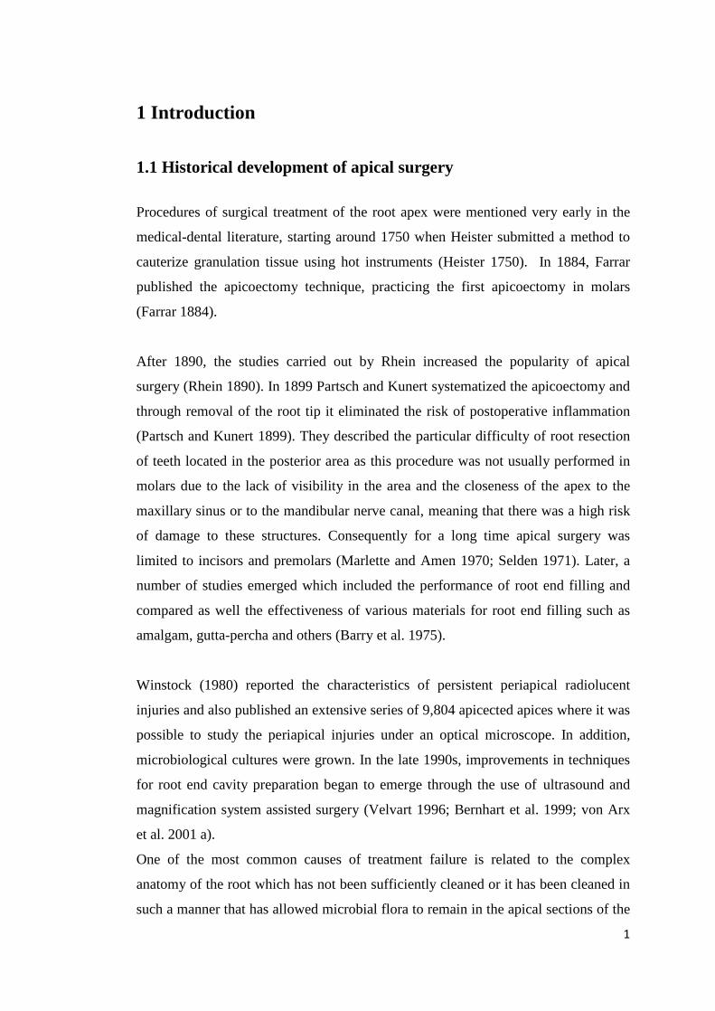
Kim and Kratchman (2006) recommend not to perform all surgical procedures on the
highest magnification, since they consider that certain procedures are better
performed with a smaller magnification, because, occasionally, the fields of view
must be broad enough to align an ultrasonic tip. Thus they categorize the procedures
according to the magnification needed (Fig. 1) and suggest that the low
magnification (x4 to x8) should be used to achieve the guidance and inspection of the
surgical site, as well as for the osteotomy.
The average magnification (x8 to x14) is used for most procedures, including
apicoectomy, preparation and sealing of the root end cavity. High magnification (x14
to x26) is mainly used to observe in detail the anatomy of the RRS after resection
and for documentation.
5
Magnification Procedures Low (x4 to x8) Orientation, inspection of the surgical site,
osteotomy, alignment of surgical tips, root end
preparation and suturing
Midrange (x8 to x14) Most surgical procedures including hemostasis.
Removal of granulation tissue, detección of root
tips, apicoectomy, root end preparation, root end
filling
High (x14 to x26) Inspection of resected root surface and root end
filling, observation of fine anatomical details,
documentation
Figure 1 Different magnifications used for different stages of endodontic surgery
(Adapted from Kim and Kratchman 2006, p. 604)
1.2.2 Endoscopic systems
Held et al. (1996) have reported on endoscopic applications in conventional therapy
and have described the first application of endoscopes as a supporting tool in apical
surgery. A few years later, Bahcall et al. (1999) described an improved endoscopic
technique for apical surgery and recommended the use of endoscopes with 6 cm
length, a lens diameter of 4 mm and an angle of 30 degrees for this procedure. They
described the use of endoscopes in the phases of root end resection for inspection of
the RRS, as a supporting tool during ultrasonic root end cavity preparation and also
during root end filling.
Von Arx et al. (2002) provided technical details on the use of endoscopes during
endodontic surgical procedures. Bahcall and Barss (2003) reported on the use of an
orascope with a 2.7 mm lens diameter, a vision angle of 70 degrees and a length of 3
cm, for visualization during endodontic surgery, and emphasized the need for having
a hemostasis of the surgical field prior to the use of the endoscope. They also
mentioned that the endoscope can provide assistance during ultrasonic
instrumentation. At the same time von Arx et al. (2003 a) reported the use of a rigid
endoscope of 3 mm lens diameter and a 70-degree angle to perform apicoectomy. 6
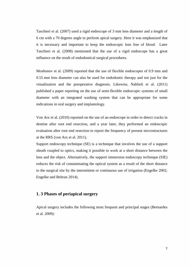
Taschieri et al. (2007) used a rigid endoscope of 3 mm lens diameter and a length of
6 cm with a 70 degrees angle to perform apical surgery. Here it was emphasized that
it is necessary and important to keep the endoscopic lens free of blood. Later
Taschieri et al. (2008) mentioned that the use of a rigid endoscope has a great
influence on the result of endodontical surgical procedures.
Moshonov et al. (2009) reported that the use of flexible endoscopes of 0.9 mm and
0.55 mm lens diameter can also be used for endodontic therapy and not just for the
visualization and the preoperative diagnosis. Likewise, Nahlieli et al. (2011)
published a paper reporting on the use of semi-flexible endoscopic systems of small
diameter with an integrated washing system that can be appropriate for some
indications in oral surgery and implantology.
Von Arx et al. (2010) reported on the use of an endoscope in order to detect cracks in
dentine after root end resection, and a year later, they performed an endoscopic
evaluation after root end resection to report the frequency of present microstructures
at the RRS (von Arx et al. 2011).
Support endoscopy technique (SE) is a technique that involves the use of a support
sheath coupled to optics, making it possible to work at a short distance between the
lens and the object. Alternatively, the support immersion endoscopy technique (SIE)
reduces the risk of contaminating the optical system as a result of the short distance
to the surgical site by the intermittent or continuous use of irrigation (Engelke 2002;
Engelke and Beltran 2014).
1. 3 Phases of periapical surgery Apical surgery includes the following most frequent and principal stages (Bernardes
et al. 2009):
7
1.3.1 Incision technique and flap design
The flap design must be chosen according to clinical parameters, for example
aesthetic and gingival biotypic parameters and the presence of any restoration on a
marginal level, among others. Also to be considered are radiographic parameters
such as location and extension of the periapical lesion and the condition of the
marginal periodontium. At this stage it is common to use an operating microscope
because it provides a general vision of the surgical field.
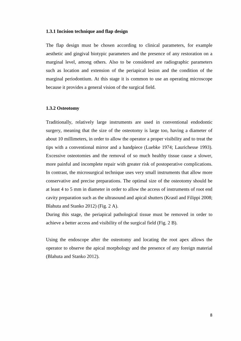
1.3.2 Osteotomy
Traditionally, relatively large instruments are used in conventional endodontic
surgery, meaning that the size of the osteotomy is large too, having a diameter of
about 10 millimeters, in order to allow the operator a proper visibility and to treat the
tips with a conventional mirror and a handpiece (Luebke 1974; Laurichesse 1993).
Excessive osteotomies and the removal of so much healthy tissue cause a slower,
more painful and incomplete repair with greater risk of postoperative complications.
In contrast, the microsurgical technique uses very small instruments that allow more
conservative and precise preparations. The optimal size of the osteotomy should be
at least 4 to 5 mm in diameter in order to allow the access of instruments of root end
cavity preparation such as the ultrasound and apical shutters (Krastl and Filippi 2008;
Blahuta and Stanko 2012) (Fig. 2 A).
During this stage, the periapical pathological tissue must be removed in order to
achieve a better access and visibility of the surgical field (Fig. 2 B).
Using the endoscope after the osteotomy and locating the root apex allows the
operator to observe the apical morphology and the presence of any foreign material
(Blahuta and Stanko 2012).
8

Figure 2 A. Scheme showing a osteotomy with round tungsten carbide drill to
access the tooth roots. ; B. Elimination of the periapical pathological tissue
1.3.3 Root end resection
Root end resection must be performed as perpendicularly as possible in relation to
the axis of the root.
Various techniques and instruments have been used to realize the resection of the
root end, such as different types of burs, laser and ultrasound devices (Duarte et al.
2007; Ayranci et al. 2015). When comparing different burs, used at high and low
speed, the Nedderman group reported that burs used at low speed and plain fissure
burs produce smoother RRS when compared to crosscut fissure burs at both low and
high speeds (Nedderman et al. 1988).
Bernardes et al. (2009) reported the use of ultrasonic tips for resection of the root
end, where they found that the carbide burs produced more regularly RRS than did
ultrasound activated CVD coated tips and that it also requires less time to perform
the apicoectomy with burs at low speed than with CVD tips.
Er: YAG and Ho: YAG lasers have also been used to realize the root end resection.
Studies by the Komori group showed that the Er: YAG laser produces cleaner and
smoother surfaces without causing thermal damage (Komori et al. 1997). It also has
advantages such as a reduced risk of trauma to the surrounding tissues, a reduced
possibility of contamination of the surgical site and less vibration and discomfort
(Komori et al. 1997). A recent study showed that tungsten carbide burs and laser
9
Er: YAG produce better cut root surfaces than the diamond-coated tip (Ayranci et al.
2015).
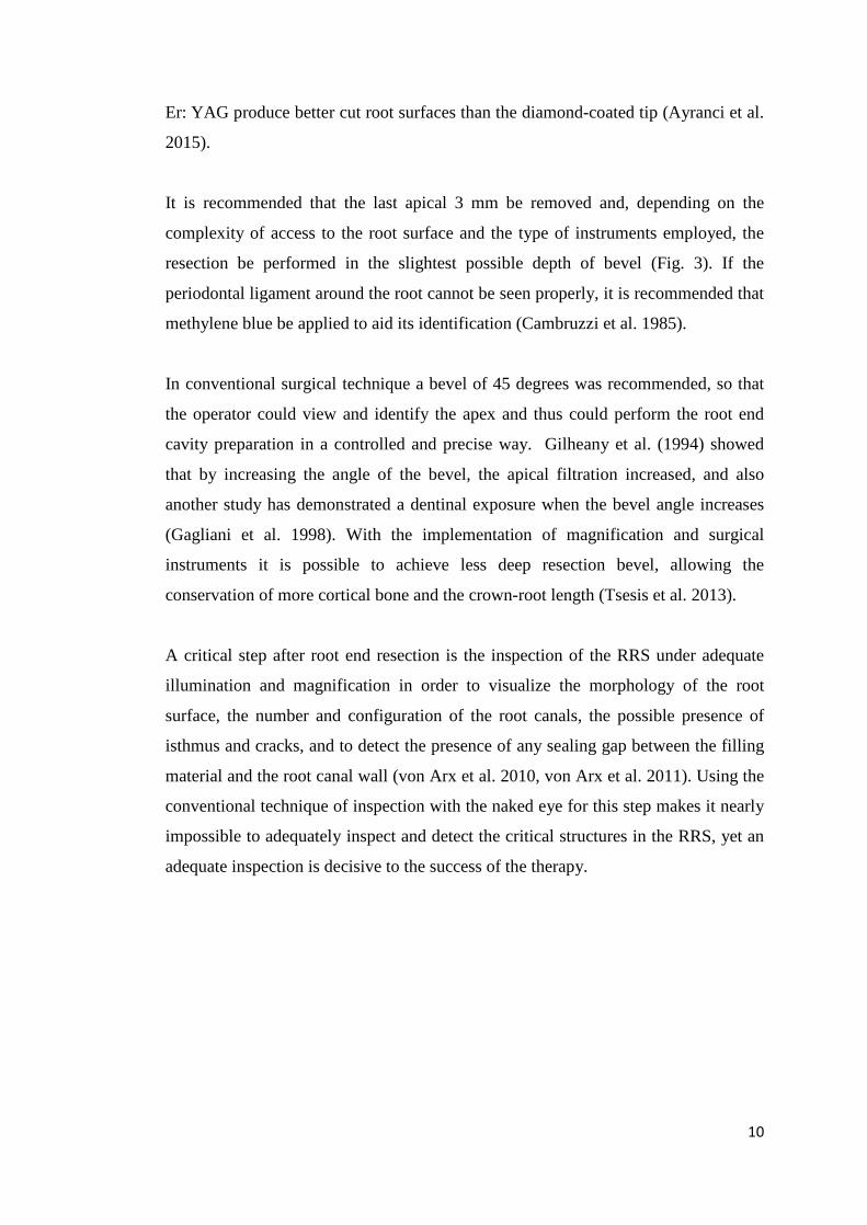
It is recommended that the last apical 3 mm be removed and, depending on the
complexity of access to the root surface and the type of instruments employed, the
resection be performed in the slightest possible depth of bevel (Fig. 3). If the
periodontal ligament around the root cannot be seen properly, it is recommended that
methylene blue be applied to aid its identification (Cambruzzi et al. 1985).
In conventional surgical technique a bevel of 45 degrees was recommended, so that
the operator could view and identify the apex and thus could perform the root end
cavity preparation in a controlled and precise way. Gilheany et al. (1994) showed
that by increasing the angle of the bevel, the apical filtration increased, and also
another study has demonstrated a dentinal exposure when the bevel angle increases
(Gagliani et al. 1998). With the implementation of magnification and surgical
instruments it is possible to achieve less deep resection bevel, allowing the
conservation of more cortical bone and the crown-root length (Tsesis et al. 2013).
A critical step after root end resection is the inspection of the RRS under adequate
illumination and magnification in order to visualize the morphology of the root
surface, the number and configuration of the root canals, the possible presence of
isthmus and cracks, and to detect the presence of any sealing gap between the filling
material and the root canal wall (von Arx et al. 2010, von Arx et al. 2011). Using the
conventional technique of inspection with the naked eye for this step makes it nearly
impossible to adequately inspect and detect the critical structures in the RRS, yet an
adequate inspection is decisive to the success of the therapy.
10
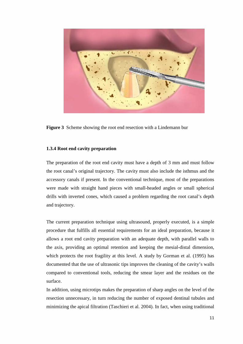
Figure 3 Scheme showing the root end resection with a Lindemann bur
1.3.4 Root end cavity preparation
The preparation of the root end cavity must have a depth of 3 mm and must follow
the root canal’s original trajectory. The cavity must also include the isthmus and the
accessory canals if present. In the conventional technique, most of the preparations
were made with straight hand pieces with small-headed angles or small spherical
drills with inverted cones, which caused a problem regarding the root canal’s depth
and trajectory.
The current preparation technique using ultrasound, properly executed, is a simple
procedure that fulfills all essential requirements for an ideal preparation, because it
allows a root end cavity preparation with an adequate depth, with parallel walls to
the axis, providing an optimal retention and keeping the mesial-distal dimension,
which protects the root fragility at this level. A study by Gorman et al. (1995) has
documented that the use of ultrasonic tips improves the cleaning of the cavity’s walls
compared to conventional tools, reducing the smear layer and the residues on the
surface.
In addition, using microtips makes the preparation of sharp angles on the level of the
resection unnecessary, in turn reducing the number of exposed dentinal tubules and
minimizing the apical filtration (Taschieri et al. 2004). In fact, when using traditional
11
techniques, a large bevel was inevitable, as the surgical tools were large, and the
bevel was only realized for the surgeon’s convenience in order to identify the apex
and to realize the subsequent root end cavity preparation (Kim 1997).
1.3.5 Root end filling
Different materials have been used to fill the root end cavity, such as amalgam,
Super EBA and glass ionomer cement. In the last decade, laboratory studies and
clinical results classify Mineral Trioxide Aggregate (MTA) as the material that best
fulfills the necessary requirements for a good sealing.
Histological studies on the response of the bone to MTA showed that this material is
associated with significant bone regeneration (Torabinejad et al. 1995). It has been
proved that its ability to achieve a hermetical seal exceeds the ability of amalgam or
Super EBA. It also shows important advantages such as excellent biocompatibility
(Camilleri and Pitt Ford 2006), it adheres well to the cavity’s walls and has low
solubility (Poggio et al. 2007), and the cement regeneration on the level of the
sectioned root surface activates cementoblasts in order to produce a matrix of cement
formation between the exposed dentine and the MTA’s surface (Bernabé et al. 2007;
von Arx 2011). This could be caused by its ability to seal hermetically, by its high
pH or by the release of substances that cause the cementoblasts’ activation in order to
deposit a matrix where cementogenesis can take place (Baek et al. 2005).
At this stage the use of magnification permits an evaluation of retrograde sealing and
makes it possible to inspect the marginal adaptation of the sealing material as well as
detect the presence of deficiencies (Blahuta and Stanko 2012). (Fig. 4)
12

Figure 4 Schem showing a filling material placed in the root end cavity
1.3.6 Wound closure
Before carrying out wound closure it is necessary to review the surgical site and to
clean it up. The reposition of the flap margins is carried out using simple individual
sutures, preferably with a fine suture material. Von Arx (2011) recommended a slight
compression with a dressing to bring the periosteal tissue in contact with the bone.
During this stage of apical surgery, magnification is not used for the cleaning of the
bone cavity, however it can be used in the case of special incisions that require very
fine sutures as for example at the base of the dental papilla (Krastl and Filippi 2008).
1.3.7 Summary of microsurgical aspects
The risk that is associated with conventional endodontic surgery in the mandibular
arch is the potential damage of the neurovascular bundles of the involved area
(Blahuta and Stanko 2012). The following are the weaknesses of the classical
periapical approaches (Gutmann 1984; Gutmann et al. 1994):
• Retrograde preparation divergent from longitudinal axis of the canal.
• Preparation with little retention.
• Preparation without a buccal-lingual extension for acceptable sealing.
13
• Preparations that weaken the apical area due to an unnecessary extension.
• Preparation that does not manage to include the isthmus area.
• Difficulty in detecting anatomical details at the RRS such as cracks.
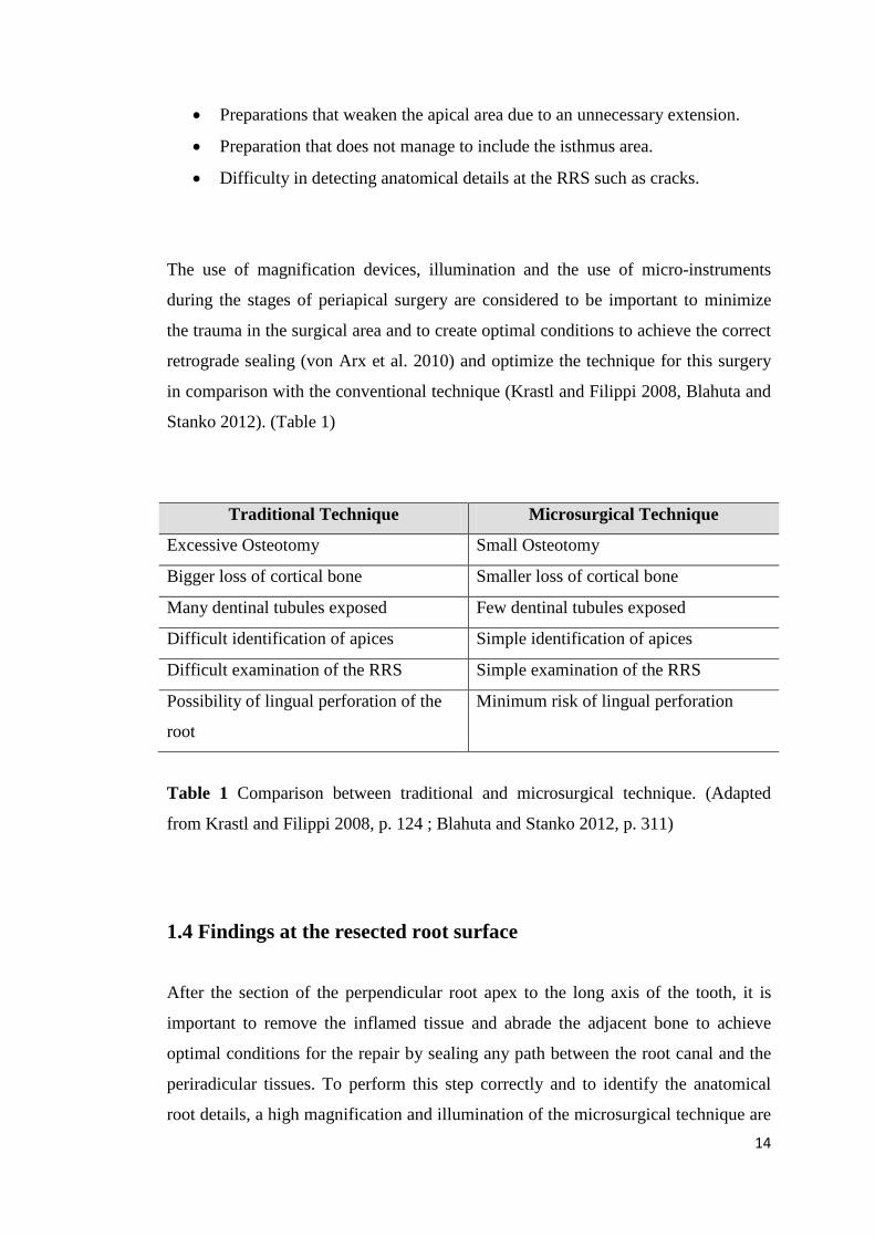
The use of magnification devices, illumination and the use of micro-instruments
during the stages of periapical surgery are considered to be important to minimize
the trauma in the surgical area and to create optimal conditions to achieve the correct
retrograde sealing (von Arx et al. 2010) and optimize the technique for this surgery
in comparison with the conventional technique (Krastl and Filippi 2008, Blahuta and
Stanko 2012). (Table 1)
Traditional Technique Microsurgical Technique
Excessive Osteotomy Small Osteotomy
Bigger loss of cortical bone Smaller loss of cortical bone
Many dentinal tubules exposed Few dentinal tubules exposed
Difficult identification of apices Simple identification of apices
Difficult examination of the RRS Simple examination of the RRS
Possibility of lingual perforation of the
root
Minimum risk of lingual perforation
Table 1 Comparison between traditional and microsurgical technique. (Adapted
from Krastl and Filippi 2008, p. 124 ; Blahuta and Stanko 2012, p. 311)
1.4 Findings at the resected root surface After the section of the perpendicular root apex to the long axis of the tooth, it is
important to remove the inflamed tissue and abrade the adjacent bone to achieve
optimal conditions for the repair by sealing any path between the root canal and the
periradicular tissues. To perform this step correctly and to identify the anatomical
root details, a high magnification and illumination of the microsurgical technique are 14
necessary. In addition, complete and critical inspection of the RRS requires working
the surface with a contrast dye such as methylene blue, which selectively dyes the
periodontal ligament and the pulp tissue (Kim and Kratchman 2006).
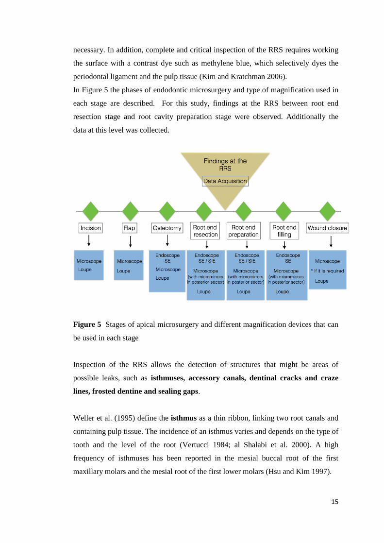
In Figure 5 the phases of endodontic microsurgery and type of magnification used in
each stage are described. For this study, findings at the RRS between root end
resection stage and root cavity preparation stage were observed. Additionally the
data at this level was collected.
Figure 5 Stages of apical microsurgery and different magnification devices that can
be used in each stage
Inspection of the RRS allows the detection of structures that might be areas of
possible leaks, such as isthmuses, accessory canals, dentinal cracks and craze
lines, frosted dentine and sealing gaps.
Weller et al. (1995) define the isthmus as a thin ribbon, linking two root canals and
containing pulp tissue. The incidence of an isthmus varies and depends on the type of
tooth and the level of the root (Vertucci 1984; al Shalabi et al. 2000). A high
frequency of isthmuses has been reported in the mesial buccal root of the first
maxillary molars and the mesial root of the first lower molars (Hsu and Kim 1997).
15
An accessory canal is defined as a canal, which has not been prepared during root
canal treatment (von Arx et al. 2003 a). The accessory canals and the isthmuses
between two canals can be considered as critical structures for the successful
outcome of apical surgery (Weller et al. 1995; Hsu and Kim 1997), for this reason
they must be recognized and properly handled.
One structure observed on the RRS and considered critical is the presence of
dentinal cracks and craze lines. Cracks are defined as apparent fissures within the
dentine while craze line was described as a dark line that appears to disrupt the
integrity of the dentine (von Arx et al. 2011). Although the clinical significance of
the cracks has not yet been well determined, it is speculated that they could be the
precursor of future apical leakage or root fractures (de Bruyne and de Moor 2005).
Another frequent finding in the RRS is an opaque area within the root dentine called
frosted dentine. The presence of this structure has been interpreted as regions of
major tension. In a study by Slaton et al. (2003), it was speculated that the frosted
dentine was caused by the formation of many microscopic cracks that had not yet
melted into a greater crack. Such areas of frosted dentine could be a precursor in the
formation of cracks; however, this relationship has not yet been clearly established.
Root fracture has been considered the cause for failure of many endodontically
treated teeth. They have been defined as fractures that extend from root surface into
canal space (Wilcox et al. 1997). Usually these fractures extend through the root
canal to the periodontal ligament dividing the root into two fragments. Vertical root
fractures are also a very important finding, whose prevalence, although not quite
established, is believed to be found more commonly in teeth that have undergone a
root canal treatment (Chang et al. 2016). A complete fracture expands in opposite
directions of the root canal and involves the movement of two fragments of the root
end (Walton et al. 1984). The presence of a sealing gap between the filling material
and the dentinal walls of the root canal is related to a bacterial route of reinfection.
16
1.5 Digital imaging in dentistry
1.5.1 General concepts of digital image and digital imaging processing
A digital image is the two-dimensional representation of a physical object from a
numerical matrix composed of binary digits. A binary number consists of digits
called bits. A bit (binary digit) is the basic information unit and represents two
possible states for a communication channel or an information storage system
(Farman 2003). The binary system consists of only two numbers, namely 0 and 1.
With a two-bit binary number only four numbers can be composed: 00, 01, 10 and
11. If a color corresponds to each of them, only four colors can be represented: black,
dark gray, light gray and white (Krupinski et al. 2007). A digital image is composed
of a finite number of elements, each with a specific place and value. These elements
are called pixels (picture elements). A pixel is represented by a code number in the
computer and it is displayed on the monitor as a point of a specific color or intensity
(Krupinski et al. 2007). Digital images are generated by the combination of pixels
that contain information related to color or tones of gray at each pixel location
(Farman 1994). In addition, the size of each pixel determines the spatial resolution of
the digital image; the smaller the size, the better the resolution of the image.
Spatial resolution refers to the ability of a device to discriminate details or, more
accurately, the ability of a device to distinguish between two points very close to
each other that can appear as a single point (Workman and Brettle 1997; Williams et
al. 2006). The resolution of a digital image depends on the number of pixels
contained in the surface unit (expressed in cm2 or in2) (Rakhshan 2014). The greater
the number of pixels per cm2, the higher is the image resolution and the spatial
definition. This depends not only on the number of pixels of the image but also on
the characteristics of the output medium. If the image is projected onto a television
screen, computer monitor, cameras or printed, the form of spatial resolution is called
"DPI resolution" or "pixel density ". It is measured by the units DPI (dots per inch)
or also PPI (pixels per inch) (Rakhshan 2014).
The final image resolution is directly proportional to the number of pixels of the
matrix and it is defined as the number of pixels per square inch and its unit is dpi or
ppi.
17
The color depth or bits per pixel (bpp) is a concept that refers to the number of bits of
information needed to represent the color of a pixel in a digital image (Larobina and
Murino 2014). In simple terms, it refers to the amount of colors that can be found in
a digital picture. The higher the number of bits, the greater is the color definition of
the image. For example, in 8-bit color mode, the color monitor uses 8 bits for each
pixel, which allows a display of 2 raised to 8 (256) different colors or shades of gray,
but it is important to note that the quality of a display system depends to a great
extent on its resolution, i.e. the number of bits used to represent each pixel
(Krupinski et al. 2007).
1.5.2 Applications using image processing software in dentistry
Digital processing or treatment of images involves algorithmic processes, which
transform an image in order to highlight certain information of interest and / or
mitigate or eliminate any information irrelevant for the application. The aim of these
processes is to modify images to improve their quality or highlight the relevant
details.
Digital tools have gradually become essential support elements for the diagnosis,
registration and projection of treatments in all areas of health where visible physical
changes and elements to manage body aesthetics are compromised. Such tools have
been successfully used for many years in areas such as plastic surgery and
dermatology through the use of indirect tools (image processing software) as well as
specific programs for each area.
Informatics, through specific software and hardware, has provided considerable and
decisive progress in the field of diagnostic imaging. Developments in information
technology have helped to improve the quality and accuracy of the image, allowing
the incorporation of new technologies or enhancing the existing ones, being of
crucial importance for the development of diagnostic imaging methods (Panetta et al.
2015). The widespread use and availability of computers with higher capacity and
faster calculation speed as well as the fast evolution of imaging systems originally
18
not available in electronic form, pave the way for a promising field of research and
technological development, generically referred to as Image Processing.
The technological development in recent years has introduced considerable
computational progress into the scientific area and it is precisely in the area of
medical imaging where scientific computing has been intensely involved. In this
way, several computer programs for scientific processing and image display have
been created and developed over the last two decades (Lehmann et al. 2002).
The use of software for image processing in dentistry was introduced in order to
improve digital images and to make it possible to observe details of the image which
cannot be visualized with the naked eye. Software has been used to identify carious
lesions by measuring the gray value scale of image pixels (Carneiro et al. 2009) and
also for measuring areas of demineralization on tooth surfaces (Murphy et al. 2007;
Nassur et al. 2013).
In periodontology some of this software has been used to evaluate the formation of
plaque in patients who were treated orthodontically (Klukowska et al. 2011) and also
to evaluate the reduction of gingival inflammation by measuring changes in redness,
using image analysis (Seshan and Shwetha 2012). In the area of orthodontics, it has
also been used for quantification of white lesions and enamel demineralization of the
surfaces with brackets (Benson et al. 2003: Livas et al. 2008)
In the area of endodontic the evaluation of gray levels and the use of tools to improve
digital images have been very useful for the description and diagnosis of bone
injuries in the apical zone when used for this purpose (Mol and van der Stelt 1992;
Scarfe et al. 1999). Other studies have used image processing in order to better
determine the working length of endodontic files inside the root canals (Piepenbring
et al. 2000) (Li et al. 2004) (Oliveira et al 2012). Other studies that have used image
processing, have improved visualization for early detection of external root
reabsorption (Poleti et al. 2014).
19
It is also possible to analyze the conventional radiograph on a computer, and
therefore it is necessary to convert radiograph into a digital image, which is called
scanning or indirect digital radiography (Versteeg et al. 1997). The digitization is
useful for the quantitative analysis of radiographs regarding the comparison of
images and this is one of the biggest advantages of storing of radiographsin a
computer, as you can perform the digital subtraction technique. When comparing
two images one can get a new one, through the differences of density. This way a
pattern of mineralization or healing of periapical lesions can be established,
permitting one to observe the areas of lower mineralization of black color, and the
areas of mineralization of white color (Brooks and Miles 1993).
The digital subtraction technique has been used to evaluate the diagnostic potential
of digital subtraction at simulated apical resorption, comparing the conventional
intraoral images with the images obtained by digital subtraction (Heo et al. 2001).
Other studies report the use of digital subtraction technique to evaluate the effect of
root canal treatment changing the size of the periapical lesions (Nicopolou-
Karayianni et al. 2002, Carvalho et al. 2009).
1.5.3 Image J in dentistry
Image J software is a public domain computer program developed in Java
programming language. It was created by Wayne Rasband in 1987 in the facilities of
the US National Institutes of Health. Later an updated version of this software was
developed in 1997 under the name of Image J, which was designed to manage
different types of image data across several computing platforms. It has also been
widely adopted by biologists due to its usefulness and ease of use. (Hartig 2013)
Image J provides a large number of tools for image editing, processing and analysis,
which can be applied to 8-bit, 16-bit and 32 bit images, and images of multiple
formats (jpg, bmp, png, gif, tiff, dicom). The tools used for image processing make it
easy to calculate a given area and the distance and angle of any user-defined
selection (Hartig 2013). In addition Image J has been able to establish connectivity
20

with other computer programs such as IMARIS, CELL Profiles (Kamentsky et al.
2011) and KNIME (Lindenbaum et al. 2011).
In regard to editing tools, Image J makes it possible to convert images from one type
to another, control advanced settings on brightness and contrast of images as well as
modify their dimensions, check their properties, manage the specific characteristics
of color images and indexed images.
Regarding analysis, it is important to mention that Image J is able to make a large
number of measurements on the image or on specific areas of the image, for example
histograms, profiles, area measurements, average brightness levels, standard
deviations, maximum and minimum values, styles, etc. In addition, the program has
tools for automatic analysis of objects in binary images and tools to calibrate such
images (spatial and density calibrations) and offers a specific set of tools for the
analysis of electrophoretic gels.
The functionality of Image J provides extensibility through an extended collection of
macros and plug-ins. Macros are a series of instructions which are stored so they can
be executed in a sequential manner through a single execution order, thus facilitating
the automation of repetitive tasks. Plug-ins are external programs, most of them
written in Java, which provide processing capabilities not found within the software
basic capabilities (Abràmoff et al. 2004). Plug-ins allow more specific tasks to be
performed by extending the program’s own tools.
In odontology, Image J has been use to compare the efficacy of debridement of
isthmus and root canals of two irrigation systems (Sarno et al. 2012, Adcock et al.
2011). Another study used Image J to compare the efficacy of cleaning by two types
of endodontic files during and after instrumentation (Saghiri et al. 2012).
A study performed by Celik et al. (2015) used Image J to measure the amount of
infiltration between adhesive systems and different surfaces of treatment. Image J
has also been used to compare and measure the apical transportation induced by
three types of rotary systems (Özer 2011).
21

1.6 Aims of study
The first part of the thesis provides an overview of the endoscopically-assisted
apical surgery procedures that were performed in the UMG from 1998 to 2015.
The following questions will be addressed:
-What is the distribution of the apical surgical procedures related to gender and age
of patients?
Null hypothesis:
There is no difference between the frequency of apical surgical procedures related to
age and gender of patients
-Are there differences in the location of the apical surgical procedures in different
oral regions?
Null hypothesis:
There is no difference between the frequency of apical surgical procedures in the
anterior region and the posterior region.
The second part of the thesis provides a descriptive and comparative analysis of
findings obtained from an examination of the RRS in the sample. The findings are
catagorized according to von Arx (2011), namely craze lines, cracks, frosted dentine
and sealing gaps. The following questions will be addressed:
-Is there a relationship between the frequency of microfindigs and age, tooth
location, presence of root post and location per root segment?
Null hypothesis:
There is no a relationship between the frequency of microfindigs and age, tooth
location, presence of root post and location per root segment 22
The third part of the thesis provides a micromorphometric analysis of findings at
the RRS after the endoscopically assisted root resecction. The following questions
will be addressed:
-Is there a relationship between frosted dentine area and extention of the crack/craze
line?
Null hypothesis:
There is no a relationship between amount of frosted dentine area and extention of
the craze lines/cracks
-Is there a relationship between the area or extention of findings and age of patients,
tooth location and presence of a root post?
Null hypothesis:
The size or extention of findings is not related to the age of the patients, type of
treated tooth, presence of a root post.
23
2 Materials and Methods
2.1 General aspects and selection of study cohort
From 1998 to 2015, a total of 237 apical endoscopically-assisted surgeries were
performed at the Department of Maxillofacial Surgery, UMG.
A total of 191 patients underwent endodontic surgery: 84 male and 107 female. The
average age was 40.7 years.
A rigid endoscopic system was used to perform all endoscopic procedures. The
following inclusion and exclusion criteria were applied to select the study cohort:
Inclusion criteria:
- Availability of endoscopic procedures from the Department of Maxillofacial
Surgery in the hospital's video archives.
- Video recordings of endoscopic surgeries of sufficient quality.
- Video recordings showing complete sequences of the root end resection phase
including inspection of the resected root surface.
- Video recordings showing a view of the RRS after resection.
- RRS images displaying only one root canal.
Exclusion criteria:
- Unavailability of endoscopic procedures from the Department of Maxillofacial
Surgery in the hospital's video archives.
- Video recordings of endoscopic surgeries of poor quality.
- Video recordings not showing complete sequences of the root end resection phase
and/or not including the inspection of the RRS.
24

After applying the inclusion and exclusion criteria, 47 patients were selected for the
study cohort, of which 21 were male and 26 were female with an average age of 44
years. 71 roots were evaluated within 56 teeth. A descriptive analysis of the
interventions was performed according to demographic parameters and tooth
location within the dental arch.
In the study cohort, findings at the RRS were analysed according to demographic
parameters and tooth location. Micromorphometry of the RRS after endoscopically-
assisted root resection in the study cohort was evaluated (Table 2).
Table 2: Diagram of the selection criteria for study cohort
25
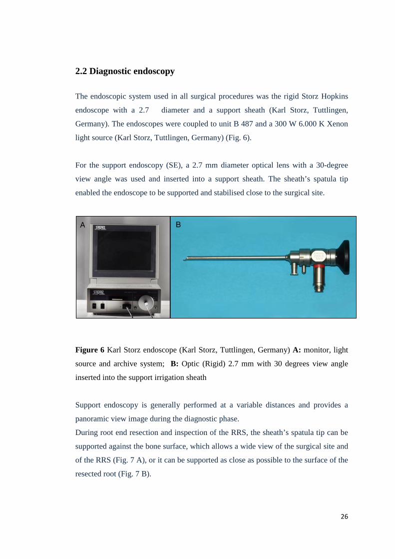
2.2 Diagnostic endoscopy
The endoscopic system used in all surgical procedures was the rigid Storz Hopkins
endoscope with a 2.7 diameter and a support sheath (Karl Storz, Tuttlingen,
Germany). The endoscopes were coupled to unit B 487 and a 300 W 6.000 K Xenon
light source (Karl Storz, Tuttlingen, Germany) (Fig. 6).
For the support endoscopy (SE), a 2.7 mm diameter optical lens with a 30-degree
view angle was used and inserted into a support sheath. The sheath’s spatula tip
enabled the endoscope to be supported and stabilised close to the surgical site.
Figure 6 Karl Storz endoscope (Karl Storz, Tuttlingen, Germany) A: monitor, light
source and archive system; B: Optic (Rigid) 2.7 mm with 30 degrees view angle
inserted into the support irrigation sheath
Support endoscopy is generally performed at a variable distances and provides a
panoramic view image during the diagnostic phase.
During root end resection and inspection of the RRS, the sheath’s spatula tip can be
supported against the bone surface, which allows a wide view of the surgical site and
of the RRS (Fig. 7 A), or it can be supported as close as possible to the surface of the
resected root (Fig. 7 B).
26
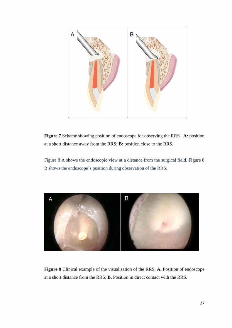
Figure 7 Scheme showing position of endoscope for observing the RRS. A: position
at a short distance away from the RRS; B: position close to the RRS.
Figure 8 A shows the endoscopic view at a distance from the surgical field. Figure 8
B shows the endoscope´s position during observation of the RRS.
Figure 8 Clinical example of the visualisation of the RRS. A. Position of endoscope
at a short distance from the RRS; B. Position in direct contact with the RRS.
27
2.3 Video footage preparation and selection
Selection of material: Classification of material was done on the basis of analogue
video recordings SVHS of endoscopically-assisted apical surgeries. Videos were
viewed with a video recorder and a colour monitor (SVHS AG 7350, Panasonic
Corporation). Videos on file were selected according to the criteria set for this study.
All video recordings showing either poor image quality, or technical faults were
excluded. All videos with incomplete recordings were excluded.
Digitizing VHS videos: Videotapes in SVHS format were converted into digital
images using a video capture device (USB 2.0 LogiLink VG0011). This device was
connected via an adapter cable from the VCR’s S-Video output (SVHAS AG 7350,
Panasonic Corporation) to the USB port in the computer, allowing data transfer from
the analogue video to the computer. The contents of the videotapes were transferred
to a computer (Dell OptiPlex 780, Dell USA) and digitized using a video-editing
program (ArcSoft ShowBitz 3.5) compatible with Microsoft Windows XP operating
system. During digitalization, each tape was played in the VCR and watched
simultaneously in a window of the computer’s colour. Using the capture function of
the video editing program, sequences of individual images were registered (final
image size 870 x 480 pixels). These photos were selected and stored in JPG format
on removable media (CD-ROM, Zip disks).
2.4 Clinical image assessment
Images of the root surface were selected immediately after apical resection during
endodontic surgery, obtained from the video register. Images were used with a
general view of the resected root surface with the support sheath placed at the border
of the bone surface as close as possible to the root.
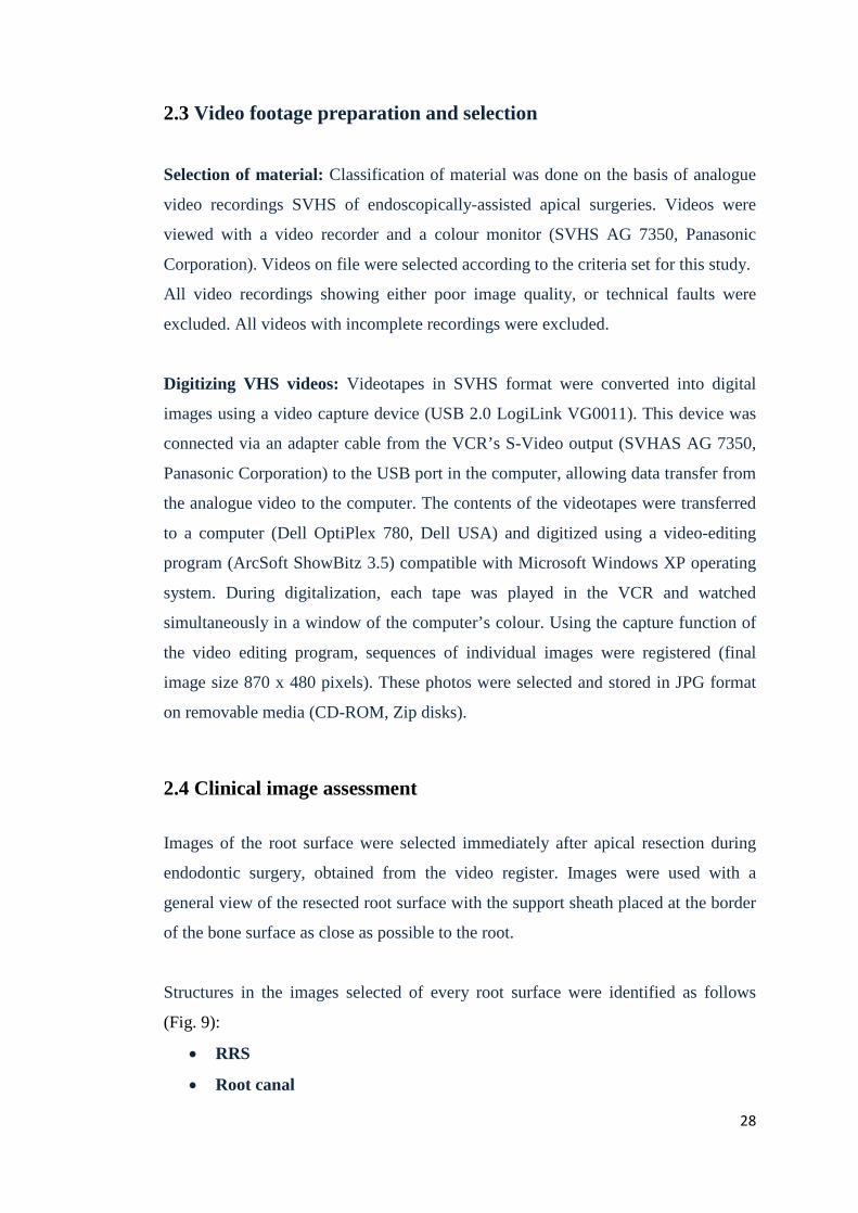
Structures in the images selected of every root surface were identified as follows
(Fig. 9):
• RRS
• Root canal
28
• Frosted dentine: whitish or opaque dentine in contrast to the normal greyish
or yellow dentine.
• Sealing gap: a space between the root canal filling material and the adjacent
dentinal wall.
• Craze line: a dark line that appears to disrupt integrity of the dentine.
• Crack: an apparent fissure within the dentine.
Figure 9 Structures that were assessed at the RRS. a: RRS; b: root canal; c: frosted
dentine; d: sealing gap; e: craze line; f: crack; M: mesial ; D: distal; B: buccal; L/P:
lingual/palatal
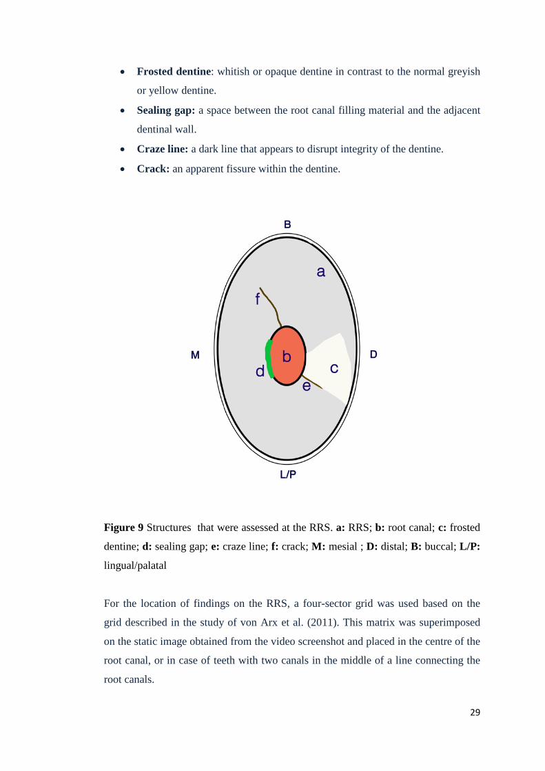
For the location of findings on the RRS, a four-sector grid was used based on the
grid described in the study of von Arx et al. (2011). This matrix was superimposed
on the static image obtained from the video screenshot and placed in the centre of the
root canal, or in case of teeth with two canals in the middle of a line connecting the
root canals.
29
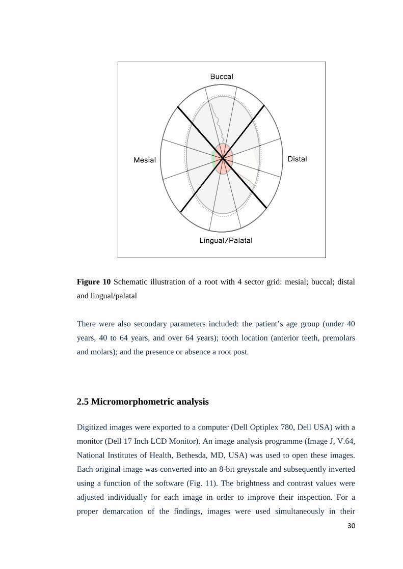
Figure 10 Schematic illustration of a root with 4 sector grid: mesial; buccal; distal
and lingual/palatal
There were also secondary parameters included: the patient’s age group (under 40
years, 40 to 64 years, and over 64 years); tooth location (anterior teeth, premolars
and molars); and the presence or absence a root post.
2.5 Micromorphometric analysis
Digitized images were exported to a computer (Dell Optiplex 780, Dell USA) with a
monitor (Dell 17 Inch LCD Monitor). An image analysis programme (Image J, V.64,
National Institutes of Health, Bethesda, MD, USA) was used to open these images.
Each original image was converted into an 8-bit greyscale and subsequently inverted
using a function of the software (Fig. 11). The brightness and contrast values were
adjusted individually for each image in order to improve their inspection. For a
proper demarcation of the findings, images were used simultaneously in their
30
original and inverted versions. Every image was laid out in so that the mesial aspect
of the RRS was placed on the left-hand side of the image, the distal aspect on the
right-hand side, the buccal aspect upwards and the lingual aspect downwards with
respect to the image.
Figure 11 Image opened in program Image J using inverted function: A. original
image; B. "inverted" function of image
1) The following measurements of the length of findings were done (Fig. 12):
• Length of craze line (5)
• Length of dentine (LD) along craze line (6)
• Length of crack (7)
• Length of dentine (LD) along crack (8)
The “straight line” function was selected from the menu of Image J to measure each
image, which allowed tracing the line of the defined finding manually. The value
was recorded and the number of pixels was read and exported to a spreadsheet (Excel
97, Microsoft Corp., Redmond, WA. USA).
2) The following width measurements of findings were performed:
• Width of craze line (5) 31

• Width of crack (7)
For measurements of findings’ width in each image, the minimal width along the
cracks and craze lines was measured. The value was recorded and the number of
pixels was read and exported to a spreadsheet (Excel 97, Microsoft Corp., Redmond,
WA, USA).
3) The following areas were measured:
• RRS area (1)
• Root canal area (2)
• Frosted dentine area (3)
• Sealing gap area (4)
For measurements of areas in each image, the “segmented line” function was
selected from the menu in Image J, which allowed tracing the outline of the defined
region manually. The value was recorded, the number of pixels was read for each
area of interest, and was then exported to a spreadsheet (Excel 97, Microsoft Corp.,
Redmond, WA, USA).
32
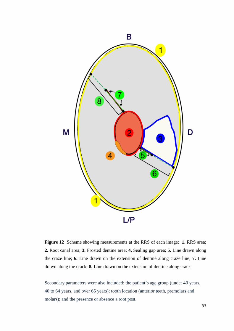
Figure 12 Scheme showing measurements at the RRS of each image: 1. RRS area;
2. Root canal area; 3. Frosted dentine area; 4. Sealing gap area; 5. Line drawn along
the craze line; 6. Line drawn on the extension of dentine along craze line; 7. Line
drawn along the crack; 8. Line drawn on the extension of dentine along crack
Secondary parameters were also included: the patient’s age group (under 40 years,
40 to 64 years, and over 65 years); tooth location (anterior teeth, premolars and
molars); and the presence or absence a root post. 33

2.6 Statistical analysis
The spreadsheets and graphs were created using Microsoft Excel 2013 (Microsoft
Corporation, Redmond, USA). Further statistical analysis were performed with SPSS
for Windows, version 16.0 (SPSS, Chicago, USA).
For the distribution of interventions of the study cohort related to demographic
parameter (gender, age) and to anatomical localization in the arch, descriptive
statistics were obtained and compared by chi square was tested .
The descriptive statistics of findings are presented as frequency tables. Associations
in two-by-two tables were tested by Fisher’s exact test. For proportions of segments
per finding exact two-sided 95% confidence intervals (Clopper–Pearson) were
computed and the null hypotheses of equal proportions within each findings were
tested by chi-square test.
For the micro-morphometric analysis, the finding were compared with demographic
parameters (age, tooth location, presence or absence of root post). All measured
values were checked by Shapiro-Wilk test and Quantile-quantile plots for normality.
For normally distributed outcomes a t-test for independent samples or One-way
ANOVA was used. Descriptive statistics included mean, standard deviation,
minimum and maximum values.
The possibility of increase of cracks lenght in the influence of increase of frosted
dentine area was calculated by Pearson´s correlation. The significance level was
uniformly set at 5%.
34

3 Results
3.1 Demographic aspects of apicoectomies
3.1.1 Distribution by gender
Of the patients studied, 21 were male (44.7%) and 26 female (55.3%). The
distribution of patients by gender is shown in Fig. 1. The distribution by gender was
assumed to be balanced. Given the small sample size no fundamental conclusions
can be deduced (Chi-squared test, p = 0.466) (Fig.13).
Figure 13 Distribution of apicoectomies by gender
3.1.2 Distribution by age
All three groups showed a normal distribution. The age of patients varied from 19 to
71 years with a mean of 40.7 years and a standard deviation of 14.1 years. The group
of 40 to 64 year-olds had the highest number of patients (51.1%), followed by the
group under 40 years (40.4%). Fewer patients were in the over 64 year-old group
(8.5%) (Chi-squared test, p = 0.001). (Fig. 14)
35
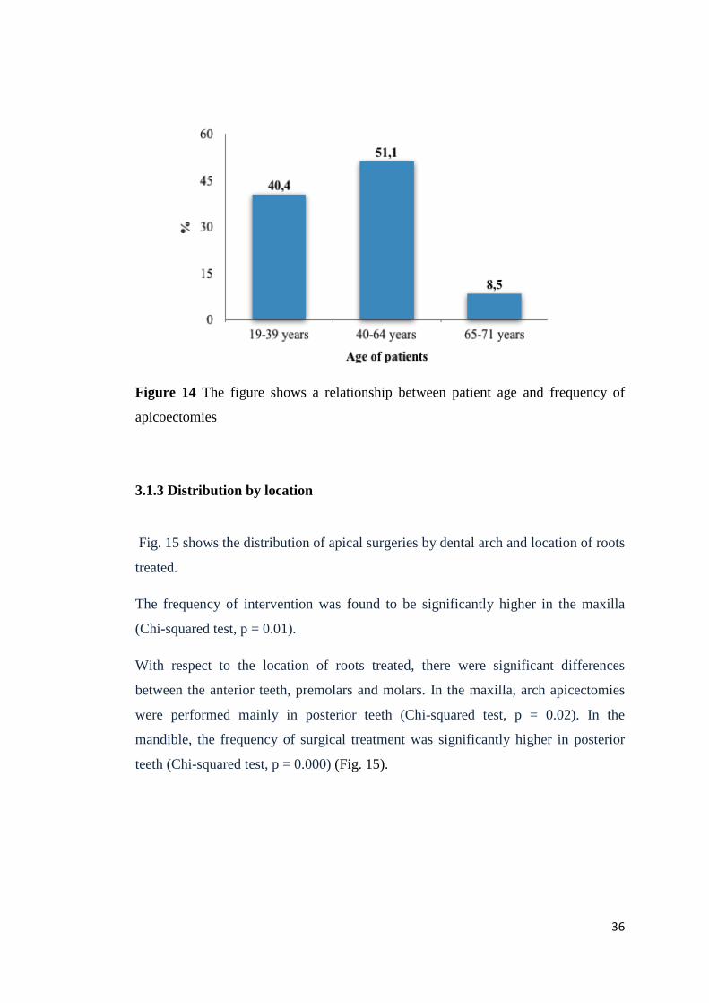
Figure 14 The figure shows a relationship between patient age and frequency of
apicoectomies
3.1.3 Distribution by location
Fig. 15 shows the distribution of apical surgeries by dental arch and location of roots
treated.
The frequency of intervention was found to be significantly higher in the maxilla
(Chi-squared test, p = 0.01).
With respect to the location of roots treated, there were significant differences
between the anterior teeth, premolars and molars. In the maxilla, arch apicectomies
were performed mainly in posterior teeth (Chi-squared test, p = 0.02). In the
mandible, the frequency of surgical treatment was significantly higher in posterior
teeth (Chi-squared test, p = 0.000) (Fig. 15).
36
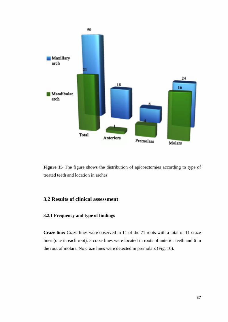
Figure 15 The figure shows the distribution of apicoectomies according to type of
treated teeth and location in arches
3.2 Results of clinical assessment
3.2.1 Frequency and type of findings
Craze line: Craze lines were observed in 11 of the 71 roots with a total of 11 craze
lines (one in each root). 5 craze lines were located in roots of anterior teeth and 6 in
the root of molars. No craze lines were detected in premolars (Fig. 16).
37
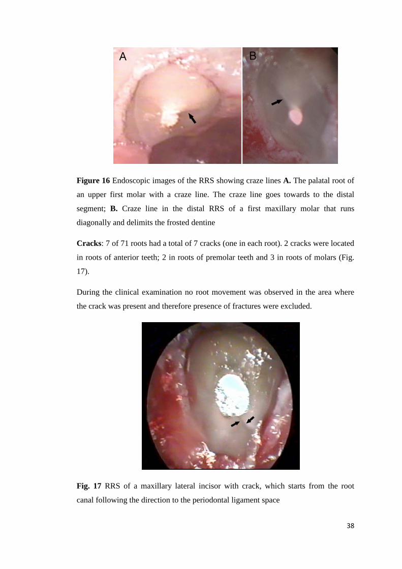
Figure 16 Endoscopic images of the RRS showing craze lines A. The palatal root of
an upper first molar with a craze line. The craze line goes towards to the distal
segment; B. Craze line in the distal RRS of a first maxillary molar that runs
diagonally and delimits the frosted dentine
Cracks: 7 of 71 roots had a total of 7 cracks (one in each root). 2 cracks were located
in roots of anterior teeth; 2 in roots of premolar teeth and 3 in roots of molars (Fig.
17).
During the clinical examination no root movement was observed in the area where
the crack was present and therefore presence of fractures were excluded.
Fig. 17 RRS of a maxillary lateral incisor with crack, which starts from the root
canal following the direction to the periodontal ligament space
38

Frosted dentine: Frosted dentine areas were observed in 67 of 71 roots, of which 17
were roots of anterior teeth, 11 roots of premolars and 25 roots of molars (Fig. 18).
Figure 18 Endoscopic images showing frosted dentine areas A Root surface of
maxillary central incisor with frosted dentine areas (black arrows) located in the
buccal sector and palatal; B. Maxillary lateral incisor with of frosted dentine, which
mainly expands the buccal segment
Sealing gaps: 12 sealing gaps were observed in 12 of 71 roots. 4 sealing gaps were
located in roots of anterior teeth , 2 in roots of premolar teeth and 6 in roots of
molars. (Fig. 19)
Figure 19 Sealing gaps at the RRS A. Resected root surface of a mesial root of a
second molar with a sealing gap between the root canal wall and the filling material;
B. Sealing gap observed at the RRS of maxillary central incisor 39
3.2.2 Findings related to patients’ age, tooth location and presence of root posts
Descriptive statistics for findings are shown as frequency tables. Fisher’s exact test
was used to evaluate associations in two-by-two tables.
Craze lines and cracks were pooled in order to calculate the correlation of
frequencies of craze lines or cracks with secondary parameters. The frequency of
craze lines/cracks was 25.4 %, frosted dentine was seen in 94.4 % and sealing gaps
in 17 % of the resected root surfaces.
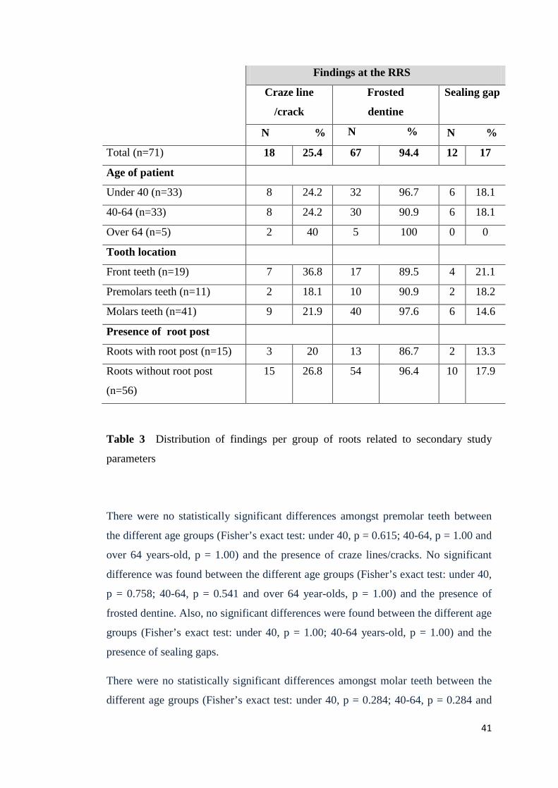
Table 3 shows the occurrence of craze lines/cracks, frosted dentine and sealing gaps
according to three different age groups (under 40 year-olds, 40-64 year-olds, over 64
year-olds). Sealing gaps were not found in the over 64 year-olds group.
There were no statistically significant differences amongst anterior teeth between the
different age groups (Fisher’s exact test: under 40, p = 0.409; 40-64, p = 0.189 and
over 64 years-old, p = 0.445) and the presence of craze lines/cracks.
No significant difference was found between the different age groups (Fisher’s exact
test: under 40 year-olds, p = 0.594; 40-64 year-olds, p = 1.00 and over 64 year-olds,
p = 0.595) and the presence of frosted dentine.
The occurrence of sealing gaps was similar (no statistically significant differences)
for the age groups (Fisher’s exact test; under 40, p = 0.166; 40-64 year-olds, p =
0.327).
40
Findings at the RRS
Craze line
/crack
Frosted
dentine
Sealing gap
N % N % N %
Total (n=71) 18 25.4 67 94.4 12 17
Age of patient
Under 40 (n=33) 8 24.2 32 96.7 6 18.1
40-64 (n=33) 8 24.2 30 90.9 6 18.1
Over 64 (n=5) 2 40 5 100 0 0
Tooth location
Front teeth (n=19) 7 36.8 17 89.5 4 21.1
Premolars teeth (n=11) 2 18.1 10 90.9 2 18.2
Molars teeth (n=41) 9 21.9 40 97.6 6 14.6
Presence of root post
Roots with root post (n=15) 3 20 13 86.7 2 13.3
Roots without root post
(n=56)
15 26.8 54 96.4 10 17.9
Table 3 Distribution of findings per group of roots related to secondary study
parameters
There were no statistically significant differences amongst premolar teeth between
the different age groups (Fisher’s exact test: under 40, p = 0.615; 40-64, p = 1.00 and
over 64 years-old, p = 1.00) and the presence of craze lines/cracks. No significant
difference was found between the different age groups (Fisher’s exact test: under 40,
p = 0.758; 40-64, p = 0.541 and over 64 year-olds, p = 1.00) and the presence of
frosted dentine. Also, no significant differences were found between the different age
groups (Fisher’s exact test: under 40, p = 1.00; 40-64 years-old, p = 1.00) and the
presence of sealing gaps.
There were no statistically significant differences amongst molar teeth between the
different age groups (Fisher’s exact test: under 40, p = 0.284; 40-64, p = 0.284 and
41
over 64 year-olds, p = 1.00) and the presence of craze lines/cracks. No significant
differences were found between the different age groups (Fisher’s exact test; under
40, p = 0.810; 40-64, p = 0.635 and over 64 year-olds, p = 0.647) and the presence of
frosted dentine. The occurrence of sealing gaps was similar (no statistically
significant differences) for the different age groups (Fisher’s exact test: under 40, p =
0.393; 40-64 years-old, p = 0.690)
Regarding the presence or absence of root post, no significant differences were found
for the occurrence of craze lines/cracks (Fisher’s exact test, p = 0.745) and sealing
gaps (Fisher’s exact test, p =1.00). Regarding root posts, we found a tendency of
their presence influencing that of frosted dentine (Fisher’s exact test, p = 0.060).
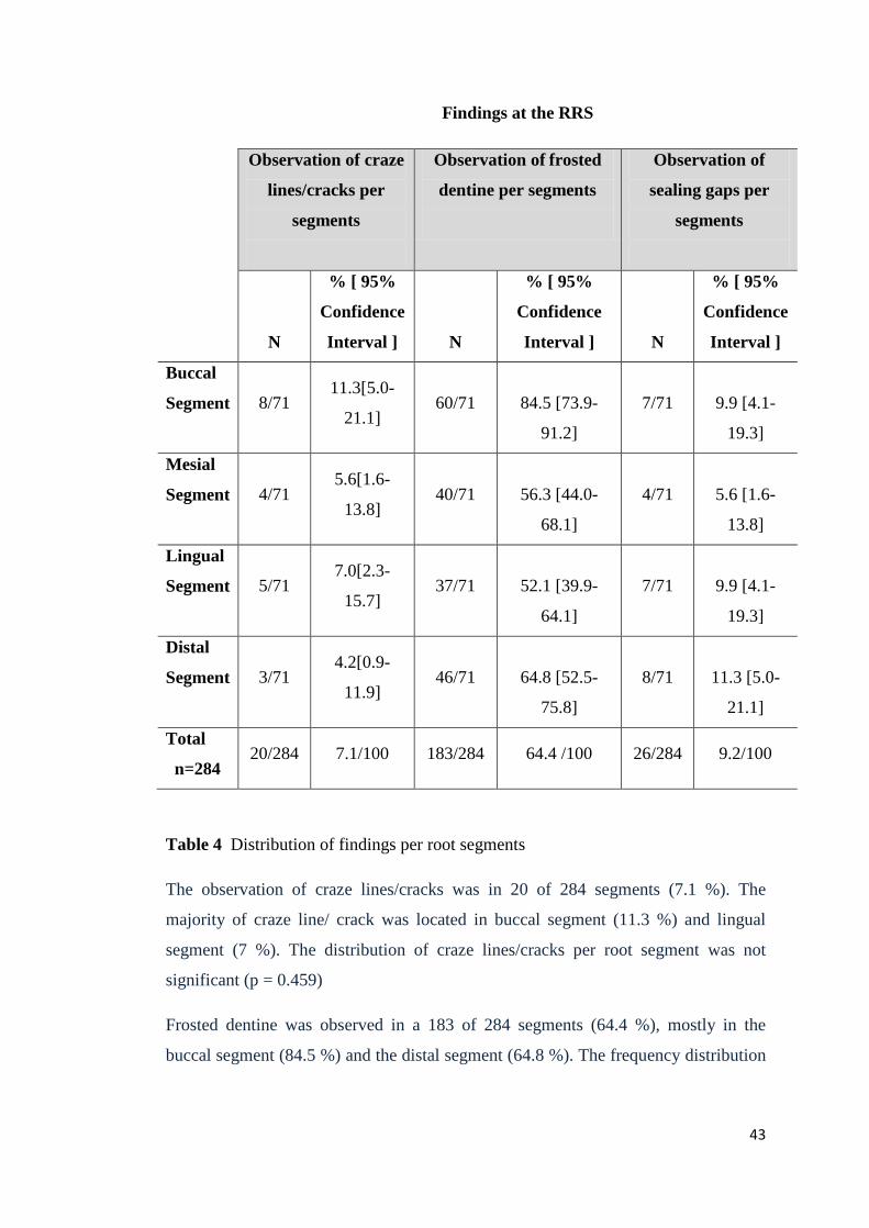
3.2.3 Distribution of findings per root segments
The distribution of craze line/crack, frosted dentine and sealing gaps per root
segment is shown in Table 4.
42
Findings at the RRS
Observation of craze
lines/cracks per
segments
Observation of frosted
dentine per segments
Observation of
sealing gaps per
segments
N
% [ 95%
Confidence
Interval ] N
% [ 95%
Confidence
Interval ] N
% [ 95%
Confidence
Interval ]
Buccal
Segment 8/71 11.3[5.0-
21.1] 60/71
84.5 [73.9-
91.2]
7/71
9.9 [4.1-
19.3]
Mesial
Segment 4/71 5.6[1.6-
13.8] 40/71
56.3 [44.0-
68.1]
4/71
5.6 [1.6-
13.8]
Lingual
Segment 5/71 7.0[2.3-
15.7] 37/71
52.1 [39.9-
64.1]
7/71
9.9 [4.1-
19.3]
Distal
Segment 3/71 4.2[0.9-
11.9] 46/71
64.8 [52.5-
75.8]
8/71
11.3 [5.0-
21.1]
Total
n=284 20/284 7.1/100 183/284 64.4 /100 26/284 9.2/100
Table 4 Distribution of findings per root segments
The observation of craze lines/cracks was in 20 of 284 segments (7.1 %). The
majority of craze line/ crack was located in buccal segment (11.3 %) and lingual
segment (7 %). The distribution of craze lines/cracks per root segment was not
significant (p = 0.459)
Frosted dentine was observed in a 183 of 284 segments (64.4 %), mostly in the
buccal segment (84.5 %) and the distal segment (64.8 %). The frequency distribution
43

of frosted dentine per segment was statistically significant (Chi-squared test, p =
0.0002).
Sealing gaps were observed in 26 of 284 segments (9.2 %), mainly in the distal
segment (11.3%). The distribution of sealing gaps per root segment was not
significant (p = 0.397).
3.3 Micromorphometric analysis
3.3.1 Descriptive evaluation
The relative length of craze lines in relation to the length of dentine along the craze
line was 43%. The relative length of cracks in relation to the length of dentine in the
crack direction was 65%.
Mean length (pixel)
SD Min value-Max value
(pixel)
Relative length pixel
(%) Length of dentine along craze line/crack (n=18)
166 70 64-308 100%
Craze line (n=11)
72 35 33-142 43%
Crack (n=7)
108 65 37-205 65%
Table 5 Relative length of craze lines and cracks in pixels
44

The measurement of width of craze line and crack calculated in pixels are presented
in the table 6
Mean width
(pixel)
Minimal value
(pixel)
Craze line 1.4 1
Crack 2.76 2.5
Table 6 Measurement of minimal width of craze lines and cracks in pixels
Table 7 shows measurements of the area of RRS and root canal area, frosted dentine
area and sealing gap area in relation to the total area of RRS in pixels.
Area pixel
(mean)
SD Min value-
Max value
(pixel)
Relativ
measurement (%)
Resected root
surface area
(n=71)
142896 93603 31634-188904 100%
Frosted dentine
area (n=67) 38365 35946 931-53672 26%
Root canal
surface area
(n=71)
8069 7253 1755-12755 5.8 %
Sealing gap area
(n=12) 2593 1981 296 -5168 1,6%
Table 7 Areas at the RRS in pixels
The relative area of frosted dentine regarding the RRS area was 26.2% and the
relative area of sealing gap in relation to RRS area was 1.6 %. The relative area of
root canals regarding the RRS area was 5.8%.
45

Craze lines and cracks were pooled in order to calculate the correlation of
morphometric analysis with secondary parameters. With regard to the correlation
between findings, there was a positive correlation between the relative area of frosted
dentine and the relative length of craze lines/cracks, therefore frosted dentine area
has an influence on extension of the craze line/crack (Pearson r = 0.008).
3.3.2 Micromorphometric data and age
Micromorphometric analysis of craze lines/cracks related to age:
Following an ANOVA test, age showed an influence on the extension of craze
lines/cracks (percentage in relation to the length of dentine along craze lines/cracks)
on the analysed RRS (p = 0.052) (Fig. 20).
Figure 20 Length of craze lines/cracks in relation to the length of dentine along
craze lines/cracks according to age of patients
46

Micromorphometric analysis of frosted dentine in relation to age:
Following an ANOVA test, no significant differences were found for frosted dentine
areas (percentage in relation to total area of RRS) when comparing the three age
groups (p = 0.128). Therefore, there was no influence of age on the area of frosted
dentine analysed on the RRS. The area of frosted dentine showed a trend and
decreased with age: the largest percentage was in the under 40-age group (28%),
followed by the 40-64 age group (25%). It was considerably lower in the over 64-
age group (15%) (Fig.21).
Figure 21 Frosted dentine areas in relation to total area of RRS according to
age of patients
47
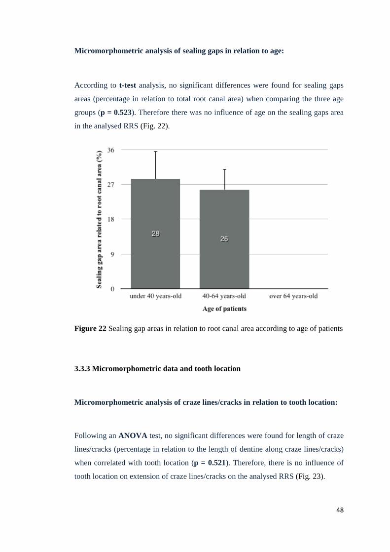
Micromorphometric analysis of sealing gaps in relation to age:
According to t-test analysis, no significant differences were found for sealing gaps
areas (percentage in relation to total root canal area) when comparing the three age
groups (p = 0.523). Therefore there was no influence of age on the sealing gaps area
in the analysed RRS (Fig. 22).
Figure 22 Sealing gap areas in relation to root canal area according to age of patients
3.3.3 Micromorphometric data and tooth location
Micromorphometric analysis of craze lines/cracks in relation to tooth location:
Following an ANOVA test, no significant differences were found for length of craze
lines/cracks (percentage in relation to the length of dentine along craze lines/cracks)
when correlated with tooth location (p = 0.521). Therefore, there is no influence of
tooth location on extension of craze lines/cracks on the analysed RRS (Fig. 23).
48
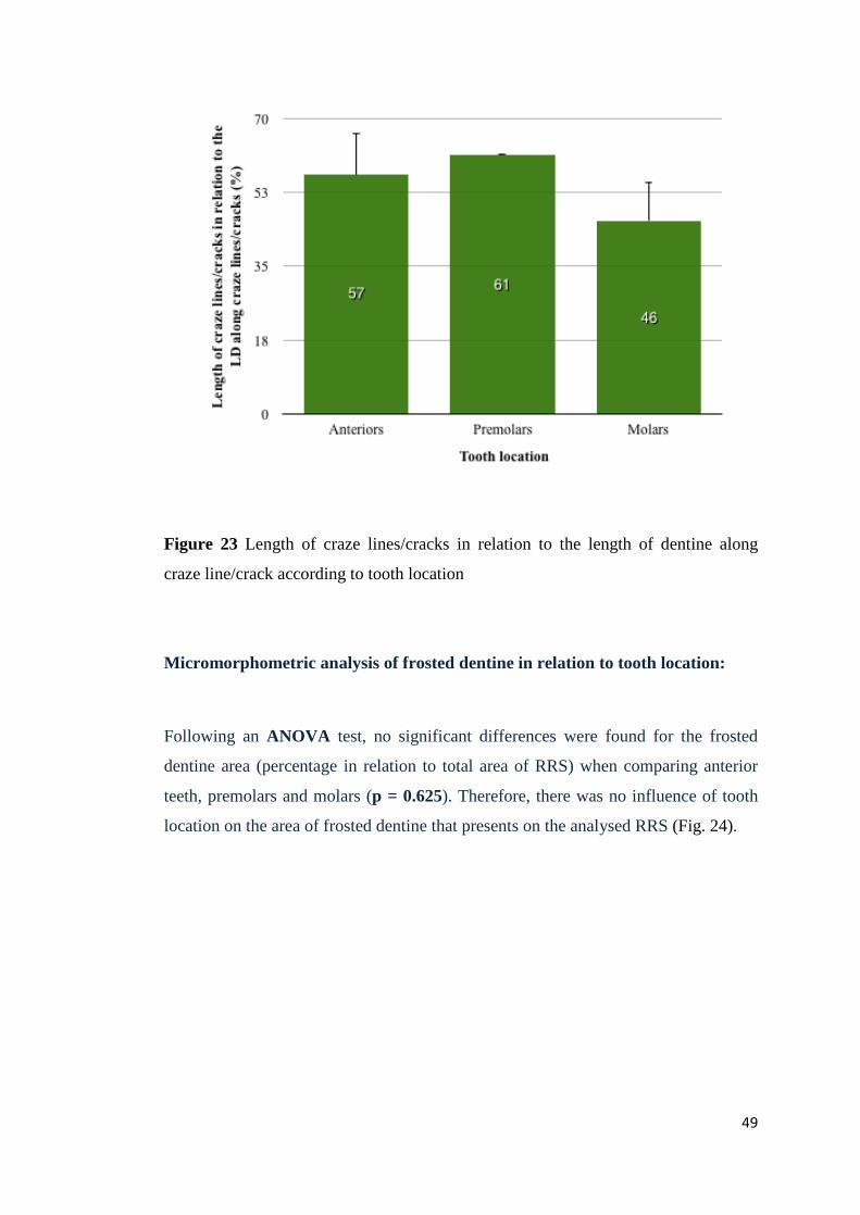
Figure 23 Length of craze lines/cracks in relation to the length of dentine along
craze line/crack according to tooth location
Micromorphometric analysis of frosted dentine in relation to tooth location:
Following an ANOVA test, no significant differences were found for the frosted
dentine area (percentage in relation to total area of RRS) when comparing anterior
teeth, premolars and molars (p = 0.625). Therefore, there was no influence of tooth
location on the area of frosted dentine that presents on the analysed RRS (Fig. 24).
49

Figure 24 Frosted dentine areas in relation to total area of RRS according to tooth
location
Micromorphometric analysis of sealing gaps in relation to tooth location:
Following an ANOVA test, no significant differences were found for the sealing
gaps areas (percentage in relation to total root canal area) when comparing tooth
location (p = 0.145). Therefore there was no influence of tooth location on the area
of sealing gaps on the analysed RRS (Fig. 25).
50
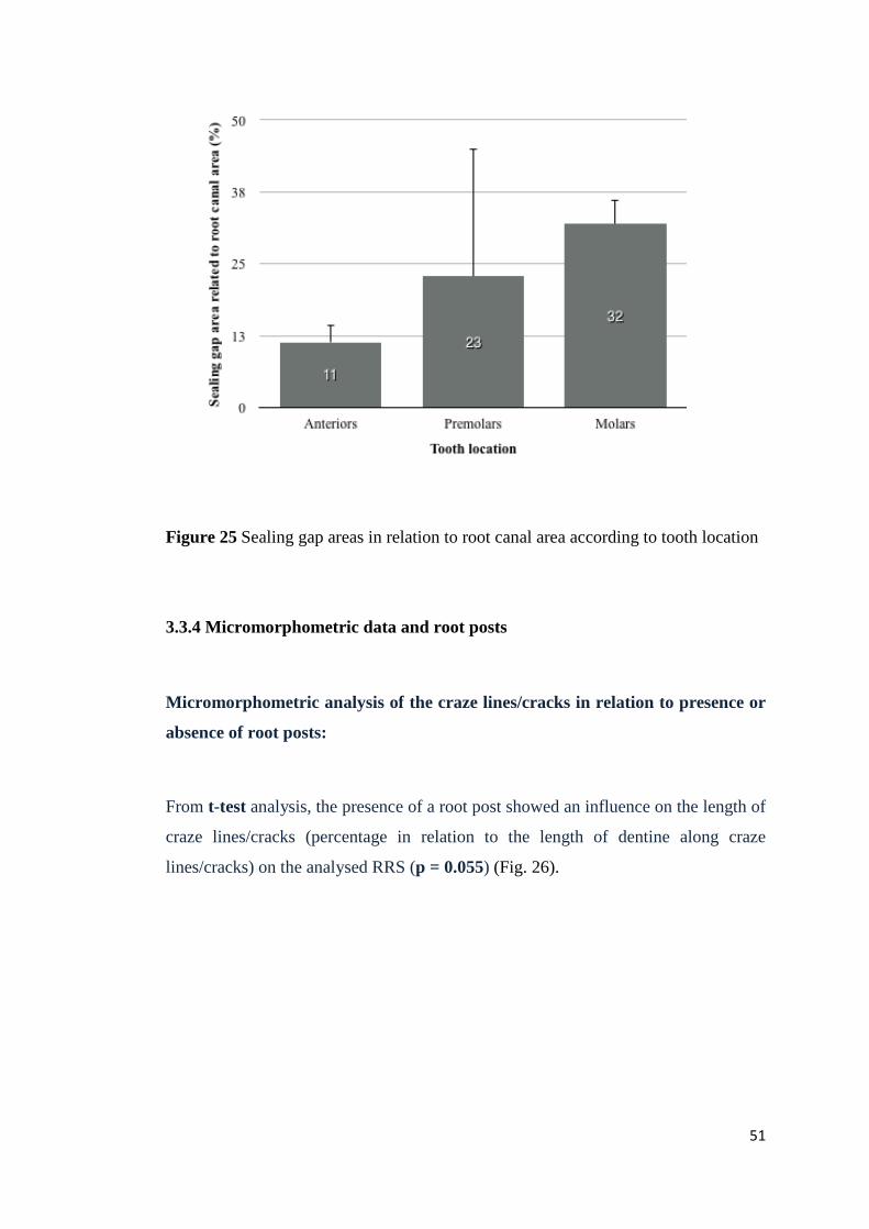
Figure 25 Sealing gap areas in relation to root canal area according to tooth location
3.3.4 Micromorphometric data and root posts
Micromorphometric analysis of the craze lines/cracks in relation to presence or
absence of root posts:
From t-test analysis, the presence of a root post showed an influence on the length of
craze lines/cracks (percentage in relation to the length of dentine along craze
lines/cracks) on the analysed RRS (p = 0.055) (Fig. 26).
51
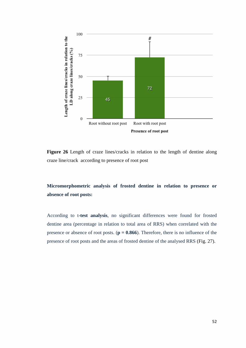
Figure 26 Length of craze lines/cracks in relation to the length of dentine along
craze line/crack according to presence of root post
Micromorphometric analysis of frosted dentine in relation to presence or
absence of root posts:
According to t-test analysis, no significant differences were found for frosted
dentine area (percentage in relation to total area of RRS) when correlated with the
presence or absence of root posts. (p = 0.866). Therefore, there is no influence of the
presence of root posts and the areas of frosted dentine of the analysed RRS (Fig. 27).
52
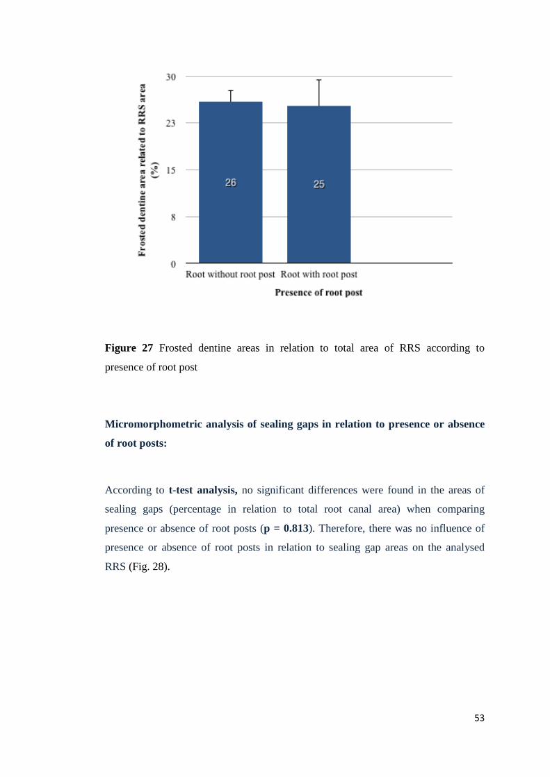
Figure 27 Frosted dentine areas in relation to total area of RRS according to
presence of root post
Micromorphometric analysis of sealing gaps in relation to presence or absence
of root posts:
According to t-test analysis, no significant differences were found in the areas of
sealing gaps (percentage in relation to total root canal area) when comparing
presence or absence of root posts (p = 0.813). Therefore, there was no influence of
presence or absence of root posts in relation to sealing gap areas on the analysed
RRS (Fig. 28).
53
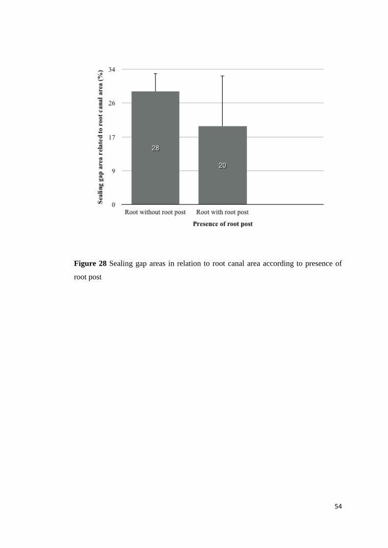
Figure 28 Sealing gap areas in relation to root canal area according to presence of
root post
54
4 Discussion
4.1 Evaluation of the RRS – Methodical aspects
For the propose of scientific evaluation, findings at the RRS were evaluated by using
either scanning electron microscopy (SEM), which is the most commonly used
method for ex vivo studies, or a combination of an endoscope with a dental operating
microscope for in vivo studies.
4.1.1 Ex vivo studies
The majority of evaluations of RRS have been performed on specimens ex vivo for
ease of procedure and for better controlled experimental conditions for different
purposes. SEM has been widely accepted and considered as the gold standard in the
analysis of RRS, but there are also reports in the literature where operating
microscopes have been used, and more recently, confocal laser scanning microscopy.
The following evaluations were focussed on the description of sealing gaps and crack
findings; Nedderman et al. (1988) used SEM with magnifications of x24, x48 and
x100 in order to observe the RRS of extracted maxillary molars and to observe the
sealing gaps after performing the apicoectomy, using different configurations of
drills at different speeds. Stabholz et al. (1992) used SEM in order to evaluate the
effect of the Nd: YAG lasers on the root end, cutting the apices of 18 teeth.
Gaglinani et al. (1998) evaluated RRS and sealing gaps, using a stereoscope at a
magnification of x12.
Slaton et al. (2003) also evaluated the frequency of artificial dentinal cracks
originating after apical resection using SEM at a magnification of x65. They
identified them and compared the sensitivity, specificity and precision of three
visualization techniques for their identification using x3.3 magnification loupes, x10
microscopes and x35 orascopes.
Another study also evaluated the frequency of cracks at the RRS and classified the
type of crack formed after apical resection and the ultrasonic root end cavity 55
preparation. To achieve this objective histological sections were cut and then
analysed by SEM at a magnification of x48 (Taschieri et al. 2004).
A study by Adorno et al. (2013) evaluated the frequency of cracks after root end
resection in order to relate the possible effect of the instrumentation and root canal
filling on the formation and propagation of cracks in the apical dentine.
In a study with stereoscopes, the cracks were quantified on the root surface after
resection and root end cavity preparation, using lasers, drills and ultrasonic tips of
zirconium on 60 maxillary anterior teeth (Aydemir et al. 2014).
Confocal laser scanning microscopy at a magnification of x20 was used in a study by
Kwak et al. (2014) in order to quantify the extent of the cracks after root end
resection with ultrasonic and diamond tips at different speeds. They also quantified
the size of the root end cavity and the remaining dentine thickness. A recent study by
Ayranci et al. (2015) quantified the cracks after root end resection in a specific
sample of mandibular premolars and used SEM at magnifications of x100 and x350
to quantify the roughness root surfaces comparing Er: YAG laser, carbide burs at low
speed and ultrasonic diamond-coated tip.
Several authors have used replicas of RRS for further analysis with SEM to avoid the
effects of drying. Morgan and Marshall (1999) made in vivo impressions of RRS
with polysiloxane and later evaluated the frequency of cracks, analysing them by
SEM at a magnification of x50.
In contrast, von Arx et al. (2003 a) evaluated the frequency of accessory canals,
sealing gaps and the presence of chipping, but also quantified cracks in a sample of
22 extracted molars. SEM was also used to compare the accuracy of endoscopic
diagnosis of RRS by analysis of the duplicates obtained after apical resection with
tungsten carbide drills and after the root end cavity preparation with diamond-coated
microtips. De Bruyne and De Moor (2005) used impressions of the root apices of
cadaveric mandibular and maxillary teeth, extracted after root end resection and after
root end cavity preparation using ultrasound with medium and low intensity. Results
were subsequently analysed them by SEM at magnifications between x20 and x35 in
order to evaluate the number and types of cracks.
56

Von Arx et al. (2010) evaluated replicas of resected root surfaces by SEM at a
greater magnification (between x50 and x200) and compared the efficiency of visual
assistance of endoscopes and microscopes at different magnifications in order to
identify and classify dentinal cracks present on the RRS within a sample of 26
extracted molars.
In summary, the above-mentioned ex vivo studies of the RRS were carried out
primarily: 1) to evaluate the effect of the different drilling systems on the RRS or
during root end cavity preparation and their correlation with the presence of findings
at the RRS such as cracks and lines of partial or complete fractures; and 2) to
evaluate the effectiveness of different instrumental and filling systems and their
correlation with the presence of cracks at the level of the cut root during apical
surgery. A third approach of these studies was to evaluate the effectiveness of
different magnification systems under ex vivo conditions in order to identify various
findings on the RRS. In this case SEM was used as the most accurate method,
compared to the use of other types of microscopes, endoscopes, or magnifying
glasses. There are no studies in the literature with specific methods to evaluate
frosted dentine.
4.1.2 In vivo studies
In vivo studies to evaluate RRS mainly at the phase of root end resection of apical
surgery have been conducted in order to observe the anatomical structures of RRS in
greater detail and to evaluate the short-term and long-term success of surgery. The
most common techniques applied to these objectives have used endoscopes and
dental operating microscopes.
Von Arx et al. (2011) evaluated the frequency and location of cracks, craze lines,
sealing gaps and frosted dentine observed during the inspection of the RRS after
root-end resection of 168 roots with endoscopic assistance at magnifications from
x80 to x100.
57
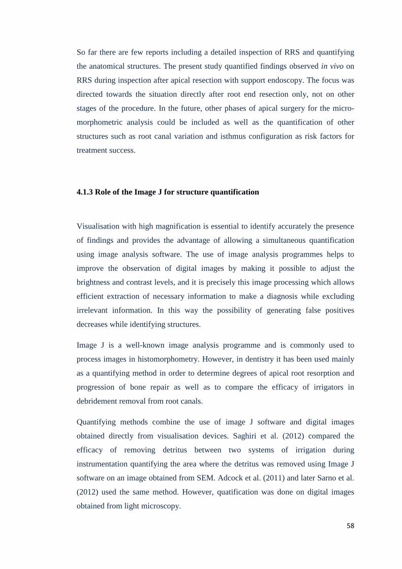
So far there are few reports including a detailed inspection of RRS and quantifying
the anatomical structures. The present study quantified findings observed in vivo on
RRS during inspection after apical resection with support endoscopy. The focus was
directed towards the situation directly after root end resection only, not on other
stages of the procedure. In the future, other phases of apical surgery for the micro-
morphometric analysis could be included as well as the quantification of other
structures such as root canal variation and isthmus configuration as risk factors for
treatment success.
4.1.3 Role of the Image J for structure quantification
Visualisation with high magnification is essential to identify accurately the presence
of findings and provides the advantage of allowing a simultaneous quantification
using image analysis software. The use of image analysis programmes helps to
improve the observation of digital images by making it possible to adjust the
brightness and contrast levels, and it is precisely this image processing which allows
efficient extraction of necessary information to make a diagnosis while excluding
irrelevant information. In this way the possibility of generating false positives
decreases while identifying structures.
Image J is a well-known image analysis programme and is commonly used to
process images in histomorphometry. However, in dentistry it has been used mainly
as a quantifying method in order to determine degrees of apical root resorption and
progression of bone repair as well as to compare the efficacy of irrigators in
debridement removal from root canals.
Quantifying methods combine the use of image J software and digital images
obtained directly from visualisation devices. Saghiri et al. (2012) compared the
efficacy of removing detritus between two systems of irrigation during
instrumentation quantifying the area where the detritus was removed using Image J
software on an image obtained from SEM. Adcock et al. (2011) and later Sarno et al.
(2012) used the same method. However, quatification was done on digital images
obtained from light microscopy.
58
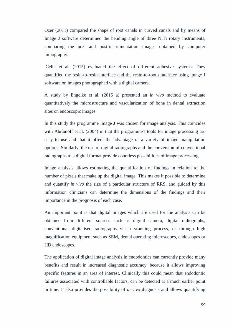
Özer (2011) compared the shape of root canals in curved canals and by means of
Image J software determined the bending angle of three NiTi rotary instruments,
comparing the pre- and post-instrumentation images obtained by computer
tomography.
Celik et al. (2015) evaluated the effect of different adhesive systems. They
quantified the resin-to-resin interface and the resin-to-tooth interface using image J
software on images photographed with a digital camera.
A study by Engelke et al. (2015 a) presented an in vivo method to evaluate
quantitatively the microstructure and vascularization of bone in dental extraction
sites on endoscopic images.
In this study the programme Image J was chosen for image analysis. This coincides
with Abràmoff et al. (2004) in that the programme's tools for image processing are
easy to use and that it offers the advantage of a variety of image manipulation
options. Similarly, the use of digital radiographs and the conversion of conventional
radiographs to a digital format provide countless possibilities of image processing.
Image analysis allows estimating the quantification of findings in relation to the
number of pixels that make up the digital image. This makes it possible to determine
and quantify in vivo the size of a particular structure of RRS, and guided by this
information clinicians can determine the dimensions of the findings and their
importance in the prognosis of each case.
An important point is that digital images which are used for the analysis can be
obtained from different sources such as digital camera, digital radiographs,
conventional digitalised radiographs via a scanning process, or through high
magnification equipment such as SEM, dental operating microscopes, endoscopes or
HD endoscopes.
The application of digital image analysis in endodontics can currently provide many
benefits and result in increased diagnostic accuracy, because it allows improving
specific features in an area of interest. Clinically this could mean that endodontic
failures associated with controllable factors, can be detected at a much earlier point
in time. It also provides the possibility of in vivo diagnosis and allows quantifying
59
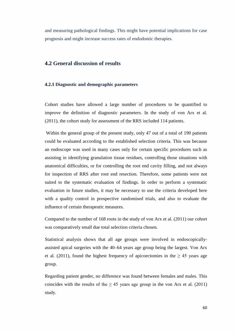
and measuring pathological findings. This might have potential implications for case
prognosis and might increase success rates of endodontic therapies.
4.2 General discussion of results
4.2.1 Diagnostic and demographic parameters
Cohort studies have allowed a large number of procedures to be quantified to
improve the definition of diagnostic parameters. In the study of von Arx et al.
(2011), the cohort study for assessment of the RRS included 114 patients.
Within the general group of the present study, only 47 out of a total of 190 patients
could be evaluated according to the established selection criteria. This was because
an endoscope was used in many cases only for certain specific procedures such as
assisting in identifying granulation tissue residues, controlling those situations with
anatomical difficulties, or for controlling the root end cavity filling, and not always
for inspection of RRS after root end resection. Therefore, some patients were not
suited to the systematic evaluation of findings. In order to perform a systematic
evaluation in future studies, it may be necessary to use the criteria developed here
with a quality control in prospective randomised trials, and also to evaluate the
influence of certain therapeutic measures.
Compared to the number of 168 roots in the study of von Arx et al. (2011) our cohort
was comparatively small due total selection criteria chosen.
Statistical analysis shows that all age groups were involved in endoscopically-
assisted apical surgeries with the 40–64 years age group being the largest. Von Arx
et al. (2011), found the highest frequency of apicoectomies in the ≥ 45 years age
group.
Regarding patient gender, no difference was found between females and males. This
coincides with the results of the ≥ 45 years age group in the von Arx et al. (2011)
study.
60
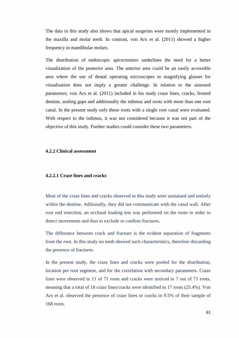
The data in this study also shows that apical surgeries were mostly implemented in
the maxilla and molar teeth. In contrast, von Arx et al. (2011) showed a higher
frequency in mandibular molars.
The distribution of endoscopic apicectomies underlines the need for a better
visualization of the posterior area. The anterior area could be an easily accessible
area where the use of dental operating microscopes or magnifying glasses for
visualisation does not imply a greater challenge. In relation to the assessed
parameters, von Arx et al. (2011) included in his study craze lines, cracks, frosted
dentine, sealing gaps and additionally the isthmus and roots with more than one root
canal. In the present study only those roots with a single root canal were evaluated.
With respect to the isthmus, it was not considered because it was not part of the
objective of this study. Further studies could consider these two parameters.
4.2.2 Clinical assessment
4.2.2.1 Craze lines and cracks
Most of the craze lines and cracks observed in this study were unstained and entirely
within the dentine. Aditionally, they did not communicate with the canal wall. After
root end resection, an occlusal loading test was performed on the roots in order to
detect movements and thus to exclude or confirm fractures.
The difference between crack and fracture is the evident separation of fragments
from the root. In this study no teeth showed such characteristics, therefore discarding
the presence of fractures.
In the present study, the craze lines and cracks were pooled for the distribution,
location per root segment, and for the correlation with secondary parameters. Craze
lines were observed in 11 of 71 roots and cracks were noticed in 7 out of 71 roots,
meaning that a total of 18 craze lines/cracks were identified in 17 roots (25.4%). Von
Arx et al. observed the presence of craze lines or cracks in 9.5% of their sample of
168 roots.
61
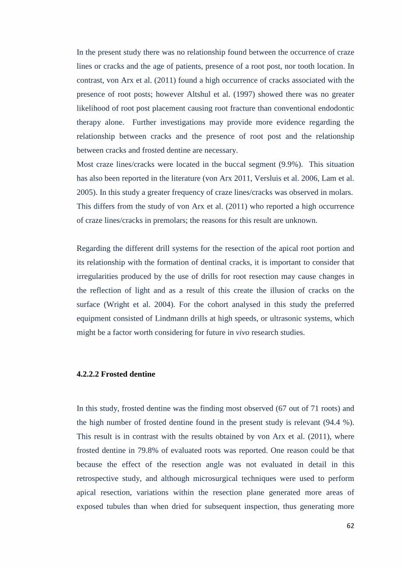
In the present study there was no relationship found between the occurrence of craze
lines or cracks and the age of patients, presence of a root post, nor tooth location. In
contrast, von Arx et al. (2011) found a high occurrence of cracks associated with the
presence of root posts; however Altshul et al. (1997) showed there was no greater
likelihood of root post placement causing root fracture than conventional endodontic
therapy alone. Further investigations may provide more evidence regarding the
relationship between cracks and the presence of root post and the relationship
between cracks and frosted dentine are necessary.
Most craze lines/cracks were located in the buccal segment (9.9%). This situation
has also been reported in the literature (von Arx 2011, Versluis et al. 2006, Lam et al.
2005). In this study a greater frequency of craze lines/cracks was observed in molars.
This differs from the study of von Arx et al. (2011) who reported a high occurrence
of craze lines/cracks in premolars; the reasons for this result are unknown.
Regarding the different drill systems for the resection of the apical root portion and
its relationship with the formation of dentinal cracks, it is important to consider that
irregularities produced by the use of drills for root resection may cause changes in
the reflection of light and as a result of this create the illusion of cracks on the
surface (Wright et al. 2004). For the cohort analysed in this study the preferred
equipment consisted of Lindmann drills at high speeds, or ultrasonic systems, which
might be a factor worth considering for future in vivo research studies.
4.2.2.2 Frosted dentine
In this study, frosted dentine was the finding most observed (67 out of 71 roots) and
the high number of frosted dentine found in the present study is relevant (94.4 %).
This result is in contrast with the results obtained by von Arx et al. (2011), where
frosted dentine in 79.8% of evaluated roots was reported. One reason could be that
because the effect of the resection angle was not evaluated in detail in this
retrospective study, and although microsurgical techniques were used to perform
apical resection, variations within the resection plane generated more areas of
exposed tubules than when dried for subsequent inspection, thus generating more
62
areas of frosted dentine. Another reason could be the misinterpretation of the frosted
dentinal zones on the images, perhaps causing the results to be biased due to
subjectivity of the examiner.
An association was found between the occurrence of frosted dentine and the presence
of a root post, which could indicate that the root post exerts some kind of tension on
the root. Neither patient´s age nor the type of treated tooth, were related to the
occurrence of frosted dentine.
An interesting fact was found in this study: all RRS with craze lines or cracks
displayed frosted dentine. In contrast, Onnink et al. (1994) found no correlation in
their investigation between the occurrence of fractures and opaque or translucent
dentine. The frequency of localisation for both findings was in the buccal segment.
Data from this research could establish a new relationship between the presence of
frosted dentine and the subsequent formation of cracks as was speculated by Slaton
et al. (2003).
Frosted dentine was observed more in the buccal segment (84.5%) than in other
segments and mainly in molars. This occurrence pattern coincides with the results of
the study by von Arx et al. (2011), who attributed the high frequency in posterior
teeth to the fact that these teeth contain more exposed dentinal tubules than the
anterior teeth bucco-lingually. They observed this finding in 134 out of 168
evaluated roots: a lower occurrence than in this study.
The causes for the presence of frosted dentine have not yet been established with
certainty. These areas in dentine have been mentioned in a previous study as areas
caused by the formation of several microscopic cracks that have not yet coalesced to
form a crack, being considered an area of great tension which increases the risk of
developing cracks or root fractures (Slaton et al. 2003). However, von Arx et al.
(2011) questioned this argumentation referring to the change in the refractive index
of the exposed dental tubules as resulting from the fact that the drying of the surface
generates a whitish appearance, thus such phenomenon should not occur in areas
with sclerotic dentine since these tubules contain dentine patterns with a similar
refractive index to the intertubular adjacent root dentine (von Arx et al. 2011).
63
More studies that focus on determining the causes of presence of frosted dentine and
the function of structural and/or optical changes occurring in the dentinal tissue of
RRS are necessary in order to evaluate their relationship with the presence of craze
lines and cracks.
4.2.2.3 Sealing gaps
Sealing gaps are one of the main causes of failure of endodontic therapy and it is
presumed that the formation of sealing gaps might have their origin in the procedures
of root canal preparation and root filling during endodontic treatment. In this study
12 sealing gaps were observed (17%). In contrast, von Arx et al. (2011) found that
the sealing gaps were the most observed finding on RRS (83.3%). The majority of
patients were referred after sufficient retrograde root canal filling only to periapical
revision, granuloma or cysts. Therefore a high incidence of sufficient root canal
fillings without sealing gaps was found.
Neither patient age, nor type of tooth, nor presence of root posts showed any
association with the occurrence of sealing gaps. These results agree with the results
of von Arx et al. (2011).
Sealing gaps were found predominantly in the distal segment (11.3%). This differs
from the results of von Arx et al. (2011), where these were located often in the
buccal segment (29.7%). In this study the frequency of sealing gaps in the buccal
segment was 9.9%.
One study shows that a possible cause explaining the presence of sealing gaps in the
buccal or lingual segment would be that these areas of the root canal show areas with
higher incidence of “wings” and that the rotating instruments probably generate
round preparations within an oval shape of the root canal and therefore these areas
are difficult to instrument (von Arx 2011). In this study, canal preparations were
performed with conventional endodontic files, whereby the location could be
explained by the influence of the technique the clinician used when performing
endodontic therapy and also by the loss of filling material during the root end
resection.
64
4.2.3 Micromorphometric aspects
4.2.3.1 Craze lines and cracks
The quantification of cracks and craze lines performed in the present study attempts
to establish morphological properties in order to achieve a structural differentiation
of the findings. Regarding the extension, the relative craze line extension is 43%,
while the relative crack extension was 65%. That indicates that cracks had bigger
extension than craze line, when they were compared with the remaining dentine of
the location where the crack or craze line had been identified.
It is possible to conclude that in the case of cracks, the extension covers more than
half of the remaining dentine thickness and this could be a critical aspect in the case
of teeth with small thickness of remaining dentine. Abedi et al. (1995) reported in
their study that more than 70% of cracks developed when the dentine walls were
smaller than 1 mm.
In a study of Kwak et al. (2014) no association between the developments of crack
with the thickness of remaining dentine was found, when it was more than 1 mm. In
both studies the length of crack and minimal thickness of remaining dentine wall
after preparation of root end cavity with ultrasound was measured.
For further studies it might be helpful to include the quantification of the extension
of a crack and the remaining dentine during intraoperative procedures to determine
its impact on the prognosis. It is important to consider that there are several types of
dentinal cracks, one of them can cover all or a part of the thickness of the dentine or
also can be within the dentine. Future quantification studies may be able to assess
these aspects more in detail.
In relation to the thickness of craze lines and cracks, the minimal width of craze line
was 1 pixel and the minimal width of crack was 2.5 pixels. This shows that the small
size of the width of craze line could be unrecognizable to the naked eye. It also
appears that the resolution of the visualisation system used in this study is limited.
Thus it is necessary to enhance the visualisation technique and to optimize the
amount of information being visualized in the display devices. 65

Future research would be valuable in supporting this observation and revealing the
clinical significance of craze lines and cracks in the intra-operative assessment of
RRS. More studies are also needed to clarify the structural differences between the
two findings since most of the previous research has mainly focused on studying the
formation of cracks and the role they play as a possible precursor of future vertical
root fractures (Morgan and Marshall 1999). So far, there is few information in the
literature related to the nature of craze lines and their clinical significance in crack
formation.
This study found that the presence of a root post increased the extent of craze
lines/cracks when present. Additionally, there was a positive correlation between the
extent of the craze lines/cracks and the amount of frosted dentine. An association
with patients' age was also found, whereby patients in the over 64 year-old group had
longer cracks.
It is important to underline that the results of this study coincide with the study of
von Arx et al. (2011) in which stated that aspects such as root canal centricity had
not been evaluated because the canal might not have been in the centre of the root
and other aspects such as the bevel of resection planes may vary and might influence
in the quantification analysis. This includes the recommendation of further studies
that should provide also a morphological analysis of the RRS at different levels.
Whether the nature of craze lines corresponds to the same nature of cracks, or if they
could be caused by an optical phenomenon cannot be determinated from the present
study. There is an additional need to determine if craze lines could be precursors of
future cracks and the clinical impact of their presence.
The method of quantification of findings at RRS used in this study could be
complemented with magnification devices to measure micro-movements intra-
operatively in vivo (Engelke et al. 2004) this techniques and it could be very useful
for differentiating fractures from cracks and craze lines.
66
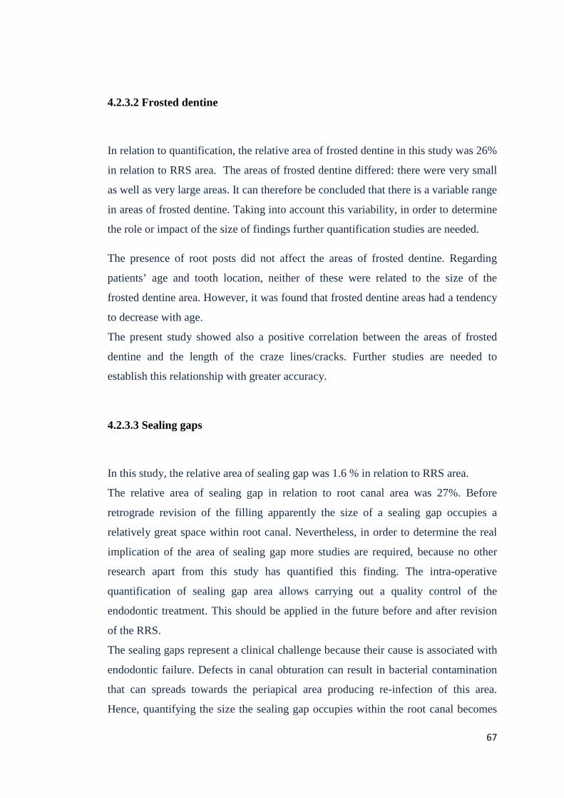
4.2.3.2 Frosted dentine
In relation to quantification, the relative area of frosted dentine in this study was 26%
in relation to RRS area. The areas of frosted dentine differed: there were very small
as well as very large areas. It can therefore be concluded that there is a variable range
in areas of frosted dentine. Taking into account this variability, in order to determine
the role or impact of the size of findings further quantification studies are needed.
The presence of root posts did not affect the areas of frosted dentine. Regarding
patients’ age and tooth location, neither of these were related to the size of the
frosted dentine area. However, it was found that frosted dentine areas had a tendency
to decrease with age.
The present study showed also a positive correlation between the areas of frosted
dentine and the length of the craze lines/cracks. Further studies are needed to
establish this relationship with greater accuracy.
4.2.3.3 Sealing gaps
In this study, the relative area of sealing gap was 1.6 % in relation to RRS area.
The relative area of sealing gap in relation to root canal area was 27%. Before
retrograde revision of the filling apparently the size of a sealing gap occupies a
relatively great space within root canal. Nevertheless, in order to determine the real
implication of the area of sealing gap more studies are required, because no other
research apart from this study has quantified this finding. The intra-operative
quantification of sealing gap area allows carrying out a quality control of the
endodontic treatment. This should be applied in the future before and after revision
of the RRS.
The sealing gaps represent a clinical challenge because their cause is associated with
endodontic failure. Defects in canal obturation can result in bacterial contamination
that can spreads towards the periapical area producing re-infection of this area.
Hence, quantifying the size the sealing gap occupies within the root canal becomes
67
clinically important because it could be considered as a factor with which to evaluate
instrumentation techniques and root obturation in order to reduce the occurrence of
sealing gaps in future. Also, the definition of a critical gap size could be an
interesting task for futures RRS evaluations.
4.3 Clinical assessment using optical systems
The success of magnification-assisted endodontic surgical treatment (surgical
microscopes with micromirrors and rigid endoscopes) can be explained by the fact
that during surgery most causes of endodontic failure can be detected with adequate
lighting and magnification, and corrected immediately. Held et al. (1996) mentioned
that the inconspicuous root apices can be displayed using a rigid endoscope, which
can also be used to reliably detect root fractures. On the other hand, Velvart (1996),
using a surgical microscope with the help of micromirrorrs pointed out the need for a
good visualisation of the operation field. He also referred to the possibility of
improving root end cavity preparation using ultrasonic instruments.
Von Arx et al. (2001 b, 2002) emphasized that endoscopes, compared to surgical
microscopes, provide a line of direct vision with a quick possibility to change the
viewing angle and permitting visualisation of otherwise non-visible regions. They
recommended the use of endoscopes for intra-operative diagnosis of RRS end and
demonstrated that success rates of apical resections were lower without the use of
endoscopes (von Arx et al. 2003 a; von Arx et al. 2003 b).
The intra-operative use of optical systems allows a proper and a homogeneous
illumination of the surgical field. In addition, work areas can be overviewed directly,
while a simultaneous view is attained of anatomical details with the use of different
magnifications (Saunders and Saunders, 1997).
There is evidence to support that microsurgical techniques, compared to
conventional techniques, provide better intraoperative diagnosis as well as the ability
to document them by means of photos and video, thus allowing the direct intra-
68
operative evaluation of the quality of procedures (von Arx et al. 2002: von Arx et al.
2003 a; von Arx et al. 2003 b).
The use of rigid endoscopes allows a safe control of the apical resection and the bone
cavity during surgery. The use of a video-endoscope allows evaluation of obturation
integrity in the existing root canal and permits identification of existing branching
and canal areas without filling on the level of the resection (von Arx et al. 2003 b).
Several authors have argued that the use of magnification during removal of apical
branching areas with bacterial contamination and during the removal of periapical
pathological tissue is a great advantage to prevent re-infection (Pecora and Andreana
1993; Kim, 1997). On the other hand, existing sealing gaps or canal areas without
endodontic filling, such as isthmuses between the root canals, can also be identified
reliably with the use of rigid endoscopes (von Arx et al. 2003 b).
Regarding the effectiveness of visualisation methods for the identification of
endodontic structures ex vivo, it has recently been proven that the combined use of
different endoscope systems can deliver high superiority in the detection of findings
even under difficult viewing conditions (Engelke et al. 2015 b). Compared to SEM,
von Arx indicated that an endoscope presents a 100% sensitivity and specificity for
identifying isthmuses or accessory canals. However, only 36% sensitivity was
reported in identifying cracks (von Arx et al. 2003 a).
Von Arx concluded that a x64 magnification endoscope allows for greater visual
accuracy in identifying cracks. But, this also delivers a great number of false
positives cracks identification due to the short distance between the root end and
optics when using a higher magnification (0.5 – 1mm) (von Arx et al. 2010). Slaton
et al. (2003) showed that microscopes presented a high specificity in the
identification of cracks (73%) compared to orascopes (63%). In addition, one study
emphasised that the use of transillumination with magnification could be very useful
in identifying cracks at the RRS (Wright et al. 2004).
Cracks and root fractures can be identified with high reliability through the
magnified field view, making it possible to determine whether apical root resection,
may still be indicated or extraction has to be performed.
69
4.4 Conclusions
The present evaluation intended to provide an improvement for the description of
clinical findings at the RRS during periapical surgery by means of endoscopic
imaging and subsequent digital image analysis. It could be demonstrated, that the
video footage obtained during routine surgery allowed (a) a qualitative description of
pathologic findings and (b) a quantitative assessment of the structural findings like
craze line, cracks, frosted dentine and sealing gaps. The latter was obtained relative
to anatomical distances (root canal diameter) and areas of the RRS (root surface
area) and may be measured in the future in absolute values by using scaled video
images.
Frosted dentine appears to be a very common phenomenon with a high incidence
mostly in the buccal segment. The measurements reveal that frosted dentine has a
variable relative area at the RRS, however is not possible to determine the impact of
this variability.
Clinically detected cracks and craze lines show significantly different extension
relative to the dentine thickness at their locations. The minimal thickness of craze
line lies at the limits of the image resolution and requires further improvement of the
visualisation tools. High-resolution visualization endoscopic could provide sufficient
image quality suitable to pimprove for quantitative assessment. The present study
could demonstrate a correlation of crack lenght and frosted dentine area, but further
studies are required to clarify this relatioship.
Quantification of sealing gap defects may be used as an instrument of quality control
for further studies.
70
5 Summary
Background:
Endoscopy combined with subsequent digital image analysis makes it possible to
survey quantitative characteristics of clinical findings in dentistry. The aim of this
study was to provide a quantitative description of diagnostic parameters of the
resected root surface (RRS) during apicoectomy.
Method:
In a general group, the analogue video recordings of 237 apicoectomies in 191
patients (84 men, 107 women, with an average age of 40.7 years) at the Department
of Oral and Maxillofacial Surgery of UMG were digitised and subsequently
evaluated. 71 apicoectomies on 47 patients fulfilled the quality criteria of a complete
representation of RRS without artefacts immediately after root end resection and
were selected for the study cohort (n = 71). Evaluation was carried out in 3 steps: (1)
Descriptive analysis of the interventions according to demographic parameters and
location in the dental arch. (2) Assessment of findings at the RRS and correlation
with parameters for age, tooth location, presence or absence of root posts and
location per root segments.
(3) Micromorphometric analysis using Image J, with description of the relative
length of craze lines and cracks and relative area of root canals, frosted dentine and
sealing gaps. The complete RRS and the transverse root diameter served as
references. The results were correlated with age, location of tooth and presence or
absence of root posts. The distribution of interventions for the study cohort related to
demographic parameters and to anatomical location, and were tested using the Chi-
squared test. Descriptive statistics of findings were presented as frequency tables.
Associations in two-by-two tables were tested using Fisher’s exact test. For
comparisons between proportions of segments per finding, exact two-sided 95%
confidence intervals (Clopper–Pearson) were calculated and the null hypotheses
were tested with the Chi-squared test. For the micro-morphometric analysis,
71
descriptive tables were presented. Values were tested for normal distribution and the
outcomes tested for correlation with demographic parameters with a t-test for
independent samples, or One-way ANOVA.
Results:
(1) In the study cohort there was no gender-specific distribution (p = 0.466) and the
interventions were made mainly in the age group between 40 and 64 years (51.1%).
Interventions were performed more frequently in the maxilla (p = 0,01), posterior
areas dominated in the maxilla (p = 0.02) and in the mandible (p < 0.001).
(2) The frequency of craze lines or cracks was 25.4%, frosted dentine 94.4% and
sealing gaps 17 % of the RRS analysed. There was no significant correlation of the
findings of craze lines/ cracks, frosted dentine, or sealing gaps with patient age or
tooth location (p > 0.05). The presence of a root post seemed to have an impact on
the occurrence of the frosted dentine (p = 0.06). The observation of craze
lines/cracks and frosted dentine was 7.1% and 64.4% of total segments respectively,
mainly in the buccal segment (11.3% and 84.5% respectively). Th observation of
sealing gaps was 9.2% of total segments, mainly distally (11.3%).
(3) In the micromorphometric analysis, the relative length of craze lines was 43%
and that of cracks was 65% in relation to the extent of dentine along craze lines or
cracks respectively. The minimal width of craze lines and cracks was 1 and 2.5
pixels respectively. The relative area of frosted dentine, root canals and sealing gaps
in relation to the total area of RRS was 26%, 5.8% and 1.6% respectively. Borderline
results arose for the length of cracks and craze lines depending on the age of the
patient (p = 0.05), the presence of a root post (p = 0.05), but not on the type of tooth
treated (p > 0.05). The frosted dentine area had an influence on the length of craze
lines and cracks (p = 0.008).
Conclusion:
The present evaluation intended to provide an improvement for the description of
clinical findings at the RRS during periapical surgery by means of endoscopic
imaging and subsequent digital image analysis.
Morphometric analysis shows, that frosted dentine appears to be a very common
phenomenon with a high incidence and variability mostly in the buccal segment.
Craze lines and cracks show significantly different extension relative to the dentine 72

thickness at their locations. The minimal thickness of craze line lies at the limits of
the image resolution and requires further improvement of the visualisation tools.
Quantification of sealing gap defects may be used as an instrument of quality control
for further studies.
73
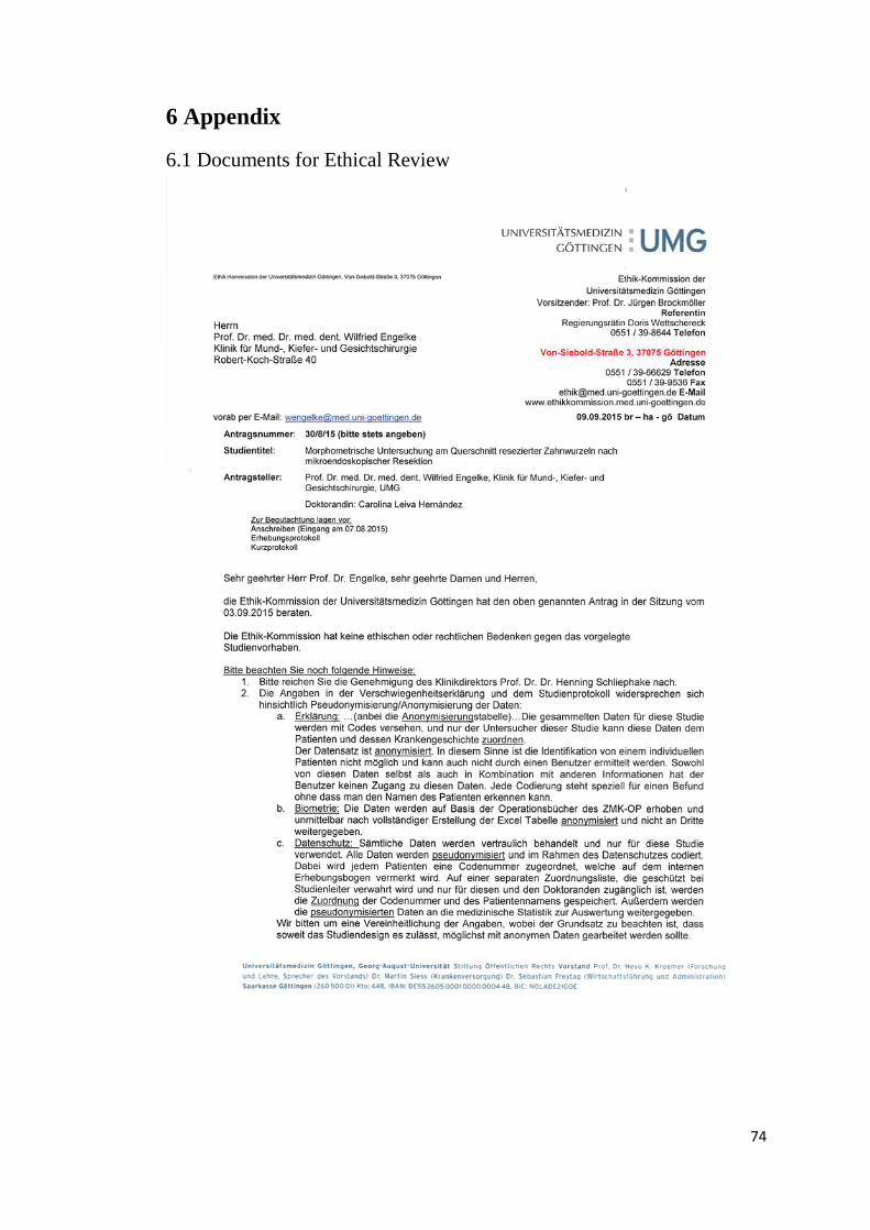
6 Appendix
6.1 Documents for Ethical Review
74
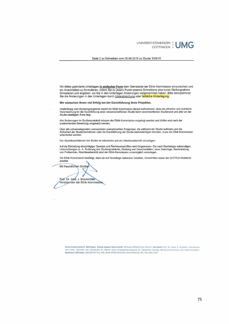
75
7 References
Abedi HR, Van Mierlo BL, Wilder-Smith P, Torabinejad M (1995): Effects of
ultrasonic root-end cavity preparation on the root apex. Oral Surg Oral Med Oral
Pathol Oral Radiol Endod 80, 207-213
Abràmoff MD, Magalhães DPJ, Ram DSJ (2004): Image processing with Image J.
Biophotonics Intern 11, 36-42
Adcock JM, Sidow SJ, Looney SW, Liu Y, McNally K, Lindsey K, Tay FR (2011):
Histologic evaluation of canal and isthmus debridement efficacies of two different
irrigant delivery techniques in a closed system. J Endod 37, 544-548
Adorno CG, Yoshioka T, Jindan P, Kobayashi C, Suda H (2013): The effect of
endodontic procedures on apical crack initiation and propagation ex vivo. Int Endod
J 46, 763-768
al Shalabi RM, Omer OE, Glennon J, Jennings M, Claffey NM (2000): Root canal
anatomy of maxillary first and second permanent molars. Int Endod J 33, 405-414
Altshul JH, Marshall G, Morgan LA, Baumgartner JC (1997): Comparison of
dentinal crack incidence and of post removal time resulting from post removal by
ultrasonic or mechanical force. J Endod 23, 683-686
Arens DE (2003): Introduction to magnification in endodontics. J Esthet Restor Dent
15, 426-439
Aydemir S, Cimilli H, Mumcu G, Chandler N, Kartal N (2014): Crack formation on
resected root surfaces subjected to conventional, ultrasonic, and laser root-end
cavity preparation. Photomed Laser Surg 32, 351-355
Ayranci F, Ayranci LB, Arslan H, Omezli MM, Topcu MC (2015): Assessment of
root surfaces of apicected teeth: a scanning electron microscopy evaluation. Niger J
Clin Pract 18, 198-202
76
Baek SH, Plenk H Jr, Kim S (2005): Periapical tissue responses and cementum
regeneration with amalgam, SuperEBA, and MTA as root-end filling materials. J
Endod 31, 444-449
Bahcall J, Barss J (2003): Orascopic visualization technique for conventional and
surgical endodontics. Int Endod J 36, 441-447
Bahcall JK, DiFiore PM, Poulakidas TK (1999): An endoscopic technique for
endodontic surgery. J Endod 25, 132-135
Barry GN, Heyman RA, Elias A (1975): Comparison of apical sealing methods. A
preliminary report. Oral Surg Oral Med Oral Pathol 39, 806-811
Benson PE, Pender N, Higham SM (2003): Quantifying enamel demineralization
from teeth with orthodontic brackets--a comparison of two methods. Part 2: validity.
Eur J Orthod 25, 159-165
Bernabé PF, Gomes-Filho JE, Rocha WC, Nery MJ, Otoboni-Filho JA, Dezan-Júnior
E (2007): Histological evaluation of MTA as a root-end filling material. Int Endod J
40, 758-765
Bernardes RA, de Souza Junior JV, Duarte MA, de Moraes IG, Bramante CM
(2009): Ultrasonic chemical vapor deposition-coated tip versus high- and low-speed
carbide burs for apicoectomy: time required for resection and scanning electron
microscopy analysis of the root-end surfaces. J Endod 35, 265-268
Bernhart T, Ulm C, Solar P, Dörtbudak O, Watzek G (1999): Die Wurzel-
spitzenresektion im Bereich des Sinus maxillaris. Schweiz Monatsschr Zahnmed
109, 937-943
Blahuta R, Stanko P (2012): The use of optical magnifying devices in periradicular
microsurgery. Bratisl Lek Listy 113, 311-313
Brooks S, Miles D (1993): Advances in diagnostic imaging in dentistry. Dent Clin
North Am 37, 91-111
Cambruzzi JV, Marshall FJ, Pappin JB (1985): Methylene blue dye: an aid to
endodontic surgery. J Endod 11, 311-314
77
Camilleri J, Pitt Ford TR (2006): Mineral trioxide aggregate: a review of the
constituents and biological properties of the material. Int Endod J 39, 747-754
Carneiro LS, Nunes CA, Silva MA, Leles CR, Mendonça EF (2009): In vivo study of
pixel grey-measurement in digital subtraction radiography for monitoring caries
remineralization. Dentomaxillofac Radiol 38, 73-78
Carvalho FB, Gonçalves M, Guerreiro-Tanomaru JM, Tanomaru-Filho M (2009):
Evaluation of periapical changes following endodontic therapy: digital subtraction
technique compared with computerized morphometric analysis. Dentomaxillofac
Radiol 38, 438-444
Carr G (1992 a): Microscopes in endodontics. J Calif Dent Assoc 20, 55
Carr G (1992 b): Advanced techniques and visual enhancement for endodontic
surgery. Endod Rep 7, 6-9
Carr GB (1997): Ultrasonic root end preparation, Dent Clin North Am 41, 541
Carr GB, Murgel CA (2010): The use of the operating microscope in endodontics.
Dent Clin North Am 54, 191-214
Celik C, Cehreli SB, Arhun N (2015): Resin composite repair: Quantitativen
microleakage evaluation of resin-resin and resin-tooth interfaces with different
surface treatments. Eur J Dent 9, 92-99
Chang E, Lam E, Shah P, Azarpazhooh A (2016): Cone-beam Computed
Tomography for Detecting Vertical Root Fractures in Endodontically Treated Teeth:
A Systematic Review. J Endod 42, 177-185
De Bruyne MA, De Moor RJ (2005): SEM analysis of the integrity of resected root
apices of cadaver and extracted teeth after ultrasonic root-end preparation at different
intensities. Int Endod J 38, 310-319
Duarte MA, Domingues R, Matsumoto MA, Padovan LE, Kuga MC (2007):
Evaluation of apical surface roughness after root resection: a scanning electron
microscopic study. Oral Surg Oral Med Oral Pathol Oral Radiol Endod 104, 74-76
78
Eichenberger M, Perrin P, Neuhaus KW, Bringolf U, Lussi A (2013): Visual acuity
of dentists under simulated clinical conditions. Clin Oral Investig 17, 725-729
Engelke WG (2002): In situ examination of implant sites with support immersion
endoscopy. Int J Oral Maxillofac Implants 17, 703-706
Engelke W, Decco OA, Rau MJ, Massoni MC, Schwarzwäller W (2004): In vitro
evaluation of horizontal implant micromovement in bone specimen with contact
endoscopy. Implant Dent 13, 88-94
Engelke W, Beltrán V: Endoskopische Verfahren in der minimal invasiven
Oralchirurgie. Endo-Press Verlag, Tuttlingen 2014
Engelke W, Lazzarini M, Stühmer W, Beltrán V (2015 a): Support Immersion
Endoscopy in Post-Extraction Alveolar Bone Chambers: A New Window for
Microscopic Bone Imaging In Vivo. PLoS One 10, e0145767
Engelke W, Leiva C, Wagner G, Beltrán V (2015 b): In vitro visualization of human
endodontic structures using different endoscope systems. Int J Clin Exp Med 8,
3234-3240
Farman AG (1994): Pixel perception and voxel vision constructs for a new paradigm
of dental care. N Y State Dent J 60, 34-37
Farman AG (2003): Fundamentals of image acquisition and processing in the digital
era. Orthod Craniofac Res. 6, 17-22
Farrar, JN (1884): Radical and heroic treatment of alveolar abscess by amputation of
roots of teeth. Dent Cosmos 26, 79-81,135-139
Gagliani M, Taschieri S, Molinari R (1998): Ultrasonic root-end preparation:
influence of cutting angle on the apical seal. J Endod 24, 726-730
Geibel MA (2006): Development of a new micro-endoscope for odontological
application. Eur J Med Res 27, 123-127
Gilheany PA, Figdor D Tyas MJ (1994): Apical dentin permeability and
microleakage associated with root end resection and retrograde filling. J Endodontic
20, 22-26
79

Gorman MC, Steiman HR, Gartner AH (1995): Scanning electron microscopic
evaluation of root-end preparations. J Endod 21, 113-117
Gutmann J (1984): Principles of endodontic surgery for the general practitioner. Dent
Clin North Am 28, 895
Gutmann JL, Saunders WP, Nguyen L, Guo JY, Saunders EM (1994): Ultrasonic
root-end preparation Part 1.SEM analysis. Int Endod J 27, 318-324
Hartig SM (2013): Basic image analysis and manipulation in ImageJ. Curr Protoc
Mol Biol Chapter 14:Unit 14.15
Heister L: Institutiones Chirurgicae. Fasc. II. Janssonio Waesbergios, Amsterdam
1750
Held SA, Kao YH, Wells DW (1996): Endoscope--an endodontic application. J
Endod 22, 327-329
Heo M, Lee S, Lee K, Choi H, Choi S, Park T (2001): Quantitative analysis of apical
root resorption by means of digital subtraction radiography. Oral Surg Oral Med Oral
Pathol 91, 369-733
Hsu YY, Kim S (1997): The resected root surface. The issue of canal isthmuses,
Dent Clin North Am 41, 529-540
Ishikawa H, Sawada N, Kobayashi C, Suda H (2003): Evaluation of root- end cavity
preparation using ultrasonic retrotips. Int Endod J 36, 586-590
Kamentsky L, Jones TR, Fraser A, Bray MA, Logan DJ, Madden KL, Ljosa V,
Rueden C, Eliceiri KW, Carpenter AE (2011): Improved structure, function and
compatibility for CellProfiler: modular high-throughput image analysis software.
Bioinformatics 15, 1179-1180
Kang M, In Jung H, Song M, Kim SY, Kim HC, Kim E (2015): Outcome of
nonsurgical retreatment and endodontic microsurgery: a meta-analysis. Clin Oral
Investig 19, 569-582
Kim, S (1997): Principles of endodontic microsurgery. Dent Clin North Am 41, 481-
498
80
Kim S, Kratchman S (2006): Modern endodontic surgery concepts and practice: a
review. J Endod 32, 601-623
Klukowska M, Bader A, Erbe C, Bellamy P, White DJ, Anastasia MK, Wehrbein H
(2011): Plaque levels of patients with fixed orthodontic appliances measured by
digital plaque image analysis. Am J Orthod Dentofacial Orthop 139, 463-470
Komori T, Yokoyama K, Takato T, Matsumoto K (1997): Clinical application of the
erbium:YAG laser for apicoectomy. J Endod 23, 748-750
Krastl G, Filippi A (2008): Optische Vergrößerungshilfen im Rahmen periradikulärer
Chirurgie. Endodontie 17, 123-131
Krupinski EA, Williams MB, Andriole K, Strauss KJ, Applegate K, Wyatt M, Bjork
S, Seibert JA; ACR; AAPM; Society for Imaging Informatics in Medicine (2007):
Digital radiography image quality: image processing and display. J Am Coll Radiol
4, 389-400
Kwak SW, Moon YM, Yoo YJ, Baek SH, Lee W, Kim HC (2014): Cutting
efficiency of apical preparation using ultrasonic tips with microprojections: confocal
laser scanning microscopy study. Restor Dent Endod 39, 276-281
Lam PP, Palamara JE, Messer HH (2005): Fracture strength of tooth roots following
canal preparation by hand and rotary instrumentation. J Endod 31, 529-532
Larobina M, Murino L (2014): Medical image file formats. J Digit Imaging 27, 200-
206
Laurichesse JM (1993): Chirurgie endodontique: nouvelles aproches, nouveaux
concepts. Tribune Dentaire 1, 21-29
Layton CA, Marshall JG, Morgan LA, Baumgartner JC (1996): Evaluation of cracks
associated with ultrasonic root-end preparation. J Endod 22, 157-160
Lehmann TM, Troeltsch E, Spitzer K (2002): Image processing and enhancement
provided by commercial dental software programs. Dentomaxillofac Radiol 31, 264-
272
81

Li G, Sanderink GC, Welander U, McDavid WD, Näsström K (2004): Evaluation of
endodontic files in digital radiographs before and after employing three image
processing algorithms. Dentomaxillofac Radiol 33, 6-11
Lindenbaum P, Le Scouarnec S, Portero V, Redon R (2011): Knime4Bio: a set of
custom nodes for the interpretation of next-generation sequencing data with KNIME.
Bioinformatics 27, 3200-3201
Livas C, Kuijpers-Jagtman AM, Bronkhorst E, Derks A, Katsaros C (2008):
Quantification of white spot lesions around orthodontic brackets with image analysis.
Angle Orthod 78, 585-890
Luebke RG (1974): Surgical endodontics. Dent Clin North Am 18, 379-391
Marlette RH, Amen CR (1970): An Evaluation of two proteolytic enzymes and
critique of the clinical study. Oral Surg 29, 249-254
Mol A, van der Stelt PF (1992): Application of computer-aided image interpretation
to the diagnosis of periapical bone lesions. Dentomaxillofac Radiol 21, 190-1904
Morgan LA, Marshall JG (1999): A scanning electron microscopic study of in vivo
ultrasonic root-end preparations. J Endod 25, 567-570
Moshonov J, Michaeli E, Nahlieli O (2009): Endoscopic root canal treatment.
Quintessence Int 40, 739-744
Murphy TC, Willmot DR, Rodd HD (2007): Management of postorthodontic
demineralized white lesions with microabrasion: a quantitative assessment. Am J
Orthod Dentofacial Orthop 131, 27-33
Nahlieli O, Moshonov J, Zagury A, Michaeli E, Casap N (2011): Endoscopic
approach to dental implantology. J Oral Maxillofac Surg 69, 186-191
Nair PN, Sjögren U, Krey G, Kahnberg KE, Sundqvist G (1990): Intraradicular
bacteria and fungi in root-filled, asymptomatic human teeth with therapy-resistant
periapical lesions: a long-term light and electron microscopic follow-up study. J
Endod 16, 580-588
82
Nassur C, Pomarico L, Maia LC (2013): Reliability analysis of two methods for
measuring active enamel demineralization: An in vitro study. Eur J Dent 7, 159-164
Navarre SW, Steiman HR (2002): Root-end fracture during retropreparation: a
comparison between zirconium nitride-coated and stainless steel microsurgical
ultrasonic instruments. J Endod 28, 330-332
Nedderman TA, Hartwell GR, Protell FR (1988): A comparison of root surfaces
following apical root resection with various burs: scanning electron microscopic
evaluation. J Endod 14, 423-427
Nicopoulou-Karayianni K, Bragger U, Patrikiou A, Stassinakis A, Lang NP (2002):
Image processing for enhanced observer agreement in the evaluation of periapical
bone changes. Int Endod J 35, 615-622
Oliveira ML, Vieira ML, Cruz AD, Bóscolo FN, DE Almeida SM (2012): Gray
scale inversion in digital image for measurement of tooth length. Braz Dent J 23,
703-706
Onnink PA, Davis RD, Wayman BE (1994): An in vitro comparison of incomplete
root fractures associated with three obturation techniques. J Endod 20, 32-37
Özer SY (2011): Comparison of root canal transportation induced by three rotary
systems with noncutting tips using computed tomography. Oral Surg Oral Med Oral
Pathol Oral Radiol Endod 111, 244-250
Panetta K, Agaian S, Pinoli JC, Zhou Y (2015): Image processing algorithms and
measures for the analysis of biomedical imaging systems applications. Int J Biomed
Imaging. 2015: 926921
Partsch C, Kunert A (1899): Über Wurzelspitzenresektion. Dtsch Monatsschr
Zahnheilk 17, 348-367
Pecora G, Andreana S (1993): Use of dental operating microscope in endodontic
surgery. Oral Surg 75, 751
Peters CI, Peters OA, Barbakow F (2001): An in vitro study comparing root-end
cavities prepared by diamond coated and stainless steel ultrasonic retrotips. Int
Endod J 34, 142-148 83
Piepenbring ME, Potter BJ, Weller RN, Loushine RJ (2000): Measurement of
endodontic file lengths: a density profile plot analysis. J Endod 26, 615-618
Poggio C, Lombardini M, Alessandro C, Simonetta R (2007): Solubility of root-end-
filling materials: a comparative study. J Endod 33, 1094-1097
Poleti ML, Fernandes TM, Paiz CC, Rubira-Bullen IR, Capelozza AL (2014): Pixel
value analysis for detection of simulated early external root resorption. Braz Oral
Res 28, 1-6
Rakhshan V (2014): Image resolution in the digital era: notion and clinical
implications. J Dent (Shiraz) 15, 153-155
Rhein ML (1890): Amputation of roots as a radical cure in chronic alveolar abscess.
Dent Cosmos 32, 904-905
Rubinstein RA, Kim S (1999): Short-term observation of the results of endodontic
surgery with the use of a surgical operating microscope and Super- EBA as root-end
filling material. J Endod 25, 43-48
Saghiri MA, Karamifar K, Mehrvazfar P, Asgar K, Gutmann JL, Lotfi M, Garcia-
Godoy F (2012): The efficacy of foam cleaners in removing debris from two
endodontic instruments. Quintessence Int 43, 811-817
Sarno MU, Sidow SJ, Looney SW, Lindsey KW, Niu LN, Tay FR (2012): Canal and
isthmus debridement efficacy of the VPro EndoSafe negative-pressure irrigation
technique. J Endod 38, 1631-1634
Saunders WP, Saunders EM (1997): Conventional endodontics and the operating
microscope. Dent Clin North Am 41, 415-428
Scarfe WC, Czerniejewski VJ, Farman AG, Avant SL, Molteni R (1999): In vivo
accuracy and reliability of color-coded image enhancements for the assessment of
periradicular lesion dimensions. Oral Surg Oral Med Oral Pathol Oral Radiol Endod
88, 603-611
Selden HS (1971): A pedicle bone flap for periapical surgery. Oral Surg 31, 654-661
84
Seshan H, Shwetha M (2012): Gingival inflammation assessment: Image analysis. J
Indian Soc Periodontol 16, 231-234
Setzer FC, Shah SB, Kohli MR, Karabucak B, Kim S (2010): Outcome of
endodontic surgery: a meta-analysis of the literature--part 1: Comparison of
traditional root-end surgery and endodontic microsurgery. J Endod 36, 1757-1765
Slaton CC, Loushine RJ, Weller RN, Parker MH, Kimbrough WF, Pashley DH
(2003): Identification of resected root-end dentinal cracks: a comparative study of
visual magnification. J Endod 29, 519-522
Stabholz A, Khayat A, Weeks DA, Neev J, Torabinejad M (1992): Scanning electron
microscopic study of the apical dentine surfaces lased with ND:YAG laser following
apicectomy and retrofill. Int Endod J 25, 288-291
Sumi Y, Hattori H, Hayashi K, Ueda M (1996): Ultrasonic root-end preparation:
clinical and radiographic evaluation of results. J Oral Maxillofac Surg 54, 590-593
Taschieri S, Testori T, Francetti L, Del Fabbro M (2004): Effects of ultrasonic root
end preparation on resected root surfaces: SEM evaluation. Oral Surg Oral Med Oral
Pathol Oral Radiol Endod 98, 611-618
Taschieri S, Del Fabbro M, Testori T, Weinstein R (2007): Endoscopic periradicular
surgery: a prospective clinical study. Br J Oral Maxillofac Surg 45, 242-244
Taschieri S, Del Fabbro M, Testori T, Weinstein R (2008): Microscope versus
endoscope in root-end management: a randomized controlled study. Int J Oral
Maxillofac Surg 37, 1022-1026
Taschieri S, Weinstein T, Tsesis I, Bortolin M, Del Fabbro M (2013): Magnifying
loupes versus surgical microscope in endodontic surgery: a four-year retrospective
study. Aust Endod J 39, 78-80
Torabinejad M, Hong CU, McDonald F, Pitt Ford TR (1995): Physical and chemical
properties of a new root-end filling material. J Endod 21, 349-353
Tsesis I, Rosen E, Taschieri S, Telishevsky Strauss Y, Ceresoli V, Del Fabbro M
(2013): Outcomes of surgical endodontic treatment performed by a modern
technique: an updated meta-analysis of the literature. J Endod 39, 332-339 85
Velvart P (1996): [The operating microscope. New dimensions in endodontics].
Schweiz Monatsschr Zahnmed 106, 356-367
Versluis A, Messer HH, Pintado MR (2006): Changes in compaction stress
distributions in roots resulting from canal preparation. Int Endod J 39, 931-939
Versteeg CH, Sanderink GC, van der Stelt PF (1997): Efficacy of digital intra-oral
radiography in clinical dentistry. J Dent 25, 215-224
Vertucci FJ (1984): Root canal anatomy of the human permanent teeth. Oral Surg
Oral Med Oral Pathol 58, 589-599
von Arx T (2011): Apical surgery: A review of current techniques and outcome.
Saudi Dent J 23, 9-15
von Arx T, Gerber C, Hardt N (2001 a): Periradicular surgery of molars: a
prospective clinical study with a one-year follow-up. Int Endod J 34, 520-525
von Arx T, Hunenbart S, Buser D (2001 b): [Endoscopy in endodontic surgery].
Schweiz Monatsschr Zahnmed 111, 1302-1310
von Arx T, Hunenbart S, Buser D (2002): Endoscope- and video-assisted endodontic
surgery. Quintessence Int 33, 255-259
von Arx T, Montagne D, Zwinggi C, Lussi A (2003 a): Diagnostic accuracy of
endoscopy in periradicular surgery - a comparison with scanning electron
microscopy. Int Endod J 36, 691-699
von Arx T, Frei C, Bornstein MM (2003 b): [Periradicular surgery with and without
endoscopy: a prospective clinical comparative study]. Schweiz Monatsschr Zahnmed
113, 860-865
von Arx T, Kunz R, Schneider AC, Bürgin W, Lussi A (2010): Detection of dentinal
cracks after root-end resection: an ex vivo study comparing microscopy and
endoscopy with scanning electron microscopy. J Endod 36, 1563-1568
von Arx T, Steiner RG, Tay FR (2011): Apical surgery: endoscopic findings at the
resection level of 168 consecutively treated roots. Int Endod J 44, 290-302
86
Walton RE, Michelich RJ, Smith GN (1984): The histopathogenesis of vertical root
fractures. J Endod 10, 48-56
Weller N, Niemczyk SP, Kim S (1995): Incidence and position of the canal isthmus.
J Endod 21, 380-383
Wilcox LR, Roskelley C, Sutton T (1997): The relationship of root canal
enlargement to finger-spreader induced vertical root fracture. J Endod 23, 533-534
Williams MB, Yaffe MJ, Maidment AD, Martin MC, Seibert JA, Pisano ED (2006):
Image quality in digital mammography: image acquisition. J Am Coll Radiol 3, 589-
608
Winstock D (1980): Apical disease: an analysis of diagnosis and management with
special reference to root lesion resection and pathology. Ann R Coll Surg Engl 62,
171-179
Workman A, Brettle DS (1997): Physical performance measures of radiographic
imaging systems. Dentomaxillofac Radiol 26, 139-416
Wright HM Jr, Loushine RJ, Weller RN, Kimbrough WF, Waller J, Pashley DH
(2004): Identification of resected root-end dentinal cracks: a comparative study of
transillumination and dyes. J Endod 30, 712-715
Zuolo ML, Perin FR, Ferreira MOF, de Faria FP (1999): Ultrasonic root-end
preparation with smooth and diamondcoated tips. Endod Dent Traumatol 15, 265-
268
87

Acknowledgements:
I would like to express my special appreciation and thanks to my advisor Prof. Dr.
med. Dr. med. dent. Wilfried Engelke, you have been a great mentor for me. I would
like to thank you for encouraging my research and for allowing me to grow as a
research scientist.
Curriculum vitae:
I was born on January 8th, 1982 in Antofagasta, Chile. I am the daughter of Resffa
Hernández and Diego Leiva. My mother is an Elementary School Principal and my
father worked for the Chilean Air Force and is now retired.
I started my Dental bachelor's degree in March 2002 and successfully finished it in
December 2008.
From March 2010 to December 2011, I attended and obtained a Post Graduate
degree in Endodontics at Universidad Andres Bello in Santiago. In 2012, I started
working as a researcher of the Faculty of Medicine of Universidad La Frontera in
Temuco and developed specialized activities for the under-graduate and post-
graduate programs.
In 2013, I was part of a research project of the Faculty of Medicine of Georg-August-
Universität Göttingen. This experience allowed me to live in Germany for the first
time and most importantly helped me in bringing new ideas to our working group in
Chile.
Since 2014 I've been living in Göttingen after earning a scholarship given by
National Commission for Scientific Research and Technology in Chile (CONICYT)
and by DAAD (Germany) to obtain my PhD in Dentistry/Georg-August-Universität.