Embed Size (px)
Citation preview

Micro Climate Monitoring System BOSCH CLIMO

A D00 A49 029 | 2017-06-09 Robert Bosch Engineering and Business Solutions Private Limited
Table of Contents 1. Symbols and safety precautions 3 1.1 Explanation of symbols 3
1.1.1 Warning notices -Structure and meaning 3
1.2 Symbols in this documentation 3 1.3 On the product 3 5.
User Interface 15 5.1 Air Quality Index 15 5.2 User Interface 15 5.3 Interpreting the outputs 15
5.3.1 To access the device through Web app 15 1.4 Important safety instructions 3 1.5 Important Notices 4 6. Troubleshooting 15
1.5.1 Don'ts 4 1.5.2 Environmental statement 4 7. Maintenance 16 1.5.3 Moving 4 1.5.4 Unpacking 4 1.5.5 3/CP300H (3.6V NI-MH BATTERY) &
8. Recommendations 16 8.1 Disposal 16
CR2032H BATTERY: 4 1.6 Enclosure safe handling instructions 5 9. Warranty 16 1.7 Short information 5
10. FCC Warning statement 15.19 17 2. BOSCH CLIMO overview 6 2.1 Version of product 6 11. FCC Warning statement 15.105 17 2.2 Applications 6 2.3 Site & Parameter selection as per CPCB
guidelines on measurement of Ambient Air 12. Statement
17 Pollutants (Air Quality) 6
2.4 Device specifications 7 13. Mobile Device 17 2.5 Technical data 8
14. RED Requirement 17 3. Pre Installation 9 3.1 Installation Kit 9 3.2 Tools 9 3.3 Torque table 9 3.4 SIM insertion (for Micro Climate Monitoring
System 3G variant AD00 A40 00) 9 3.5 configuration (Micro Climate Monitoring
System variant AD00 A40 002 9 3.6 Ethernet and USB connectors 9
3.6.1 Panel mount connectors 9 3.6.2 Mating connectors 9
3.7 Calibration 10 3.8 Health indicators 10 3.9 Pre installation Acceptance checklist 10 3.10 Post installation Acceptance checklist 11
4. Installation 12 4.1 Unpacking 12 4.2 Installing SIM 12 4.3 Mounting bracket assembly 12 4.4 Pole mounting 13 4.5 Wall mounting 13 4.6 Sun shade and UV sensor assembly 13 4.7 Splash guard and CO2 sensor assembly 14 4.8 AC DC connection 14
en 2 |
A D00 A49 029 | 2017-06-09Robert Bosch Engineering and Business Solutions Private Limited
|
1. Symbols and safetyprecautions
1.1 Explanation of symbols 1.1.1 Warning notices -
Structure and meaning Warning notices warn of dangers to the user or people in the vicinity. Warning notices also indicate the consequences of the hazard as well as preventive action. Warning notices have the following structure:
Abbreviations used in this manual:
Warning symbol
KEY WORD – Nature and source of hazard! Consequences of hazard in the event of failure to observe action and information given.
➢ Hazard prevention action and information.
The key word indicates the likelihood of occurrence and the severity of the hazard in the event of non-observance
Key word Probability of occurrence
Severity of danger if instructions not observed
DANGER Immediate impending danger
Death or severe injury
WARNING Possible impending danger
Death or severe injury
CAUTION Possible dangerous situation
Minor injury
1.4 Important safety instructions
Read, follow, and retain for future reference all of the following safety instructions before operating the unit. • Do not install or store the unit near any heat sources
such as radiators, heaters, stoves, or other equipment(including amplifiers) that produce heat.
• Do not block or cover any of the openings provided inthe unit. They are provided for ventilation, to preventfrom overheating and to ensure reliable operation.Keep open distance of approximate 200mm all roundthe unit.
• Do not place objects filled with liquids, such as vasesor cups on the unit. Never spill liquid of any kind onthe unit.
• Do not open the mating connector and dust cap in rainy1.2 Symbols in this documentation
Symbol Designation Explanation ! Attention Warns about possible property damage. i Information Practical hints and other useful
information.1. 2.
Multi-step operation
Instruction consisting of several steps.
1.3 On the product
! Observe all warning notices on products and ensurethey remain legible.
season, as the water might enter the unit and lead to fire or electrical shock.
• Disconnect the electrical connection before cleaning. Use only a dry cloth. Do not use liquid cleaners or aerosol cleaners.
• Do not attempt to service a damaged device yourself,unless qualified. Contact your associated channelpartner for all types of servicing, such as– The power supply cord or plug is damaged;– Sensor damaged due to exposure of moisture,
water, and/or inclement weather (rain, snow,etc.);
– Liquid has been spilled in or on the equipment;– Unit has been dropped or the unit cabinet is
damaged;– Unit exhibits a distinct change in performance;– Unit does not operate normally when the user
correctly follows the operating instructions.• Install in accordance with the manufacturer's
instructions in accordance with applicable localcodes.
• Use only attachments or accessories specified bythe manufacturer. Equipment change or modificationcould void the user's guarantee or authorizationagreement.
Symbols and safety precautions | 3 en
AQI Air Quality Index
IoT Internet of Things IP Ingress Protection PCB Printed Circuit Board PSK Pre-Shared Key SIM Subscriber Identity Module

A D00 A49 029 | 2017-06-09 Robert Bosch Engineering and Business Solutions Private Limited
• Be sure that the service technician uses replacement parts specified by the manufacturer, or that which have the same characteristics as the original parts. Unauthorized substitutions may cause injuries or other hazards.
i The IMPORTANT SAFEGUARDS and WARNINGS presented in this manual do not cover all possible conditions that may occur. Common sense, caution and care must be exercised when installing, maintaining or operating the unit.
1.5 Important Notices
Accessories - Do not place this unit on an
unstable stand, tripod, bracket, or mount. The unit may fall, causing serious injury and/or serious damage to the unit. Use only with mounting solutions specified by the manufacturer. When a cart is used, use caution and care when moving the cart/unit combination to avoid injury from tip-over. Quick stops, excessive force, or uneven surfaces may cause the cart/unit combination to overturn. Mount the unit as per the installation instructions. .
1.5.1 Don'ts • Do not connect the unit to the electrical power supply
using cables that have been damaged. • Do not remove any of the connectors. • Do not keep the unit below water body and water
pipes. • Do not keep the unit in temperature range other than
indicated in recommendation section. • Do not power the unit with other power sources than
the original provided by RBEI. Voltage and current maximum ratings can be exceeded, stopping unit from working and voiding warranty.
• Do not try to extract, screw, break or move connectors far from necessary usage, waterproof sealing can be damaged and warranty will be voided.
• Do not connect any sensor not provided by RBEI. • Do not place nodes on places or equipment where
it could be exposed to shocks and/or big vibrations. • Do not keep mating connectors or dust caps in unlock
condition. • Do not use dropped unit. • Do not replace the sensor or any parts in the mounting
condition. • Do not carry the unit in assembled condition (with sun
shade, splash guard, hose clamp and screw hardware). • Do not mishandle CO2 and UV sensor as it may cause
reading disturbance due to vibration or shock.
1.5.2 Environmental statement Bosch has a strong commitmenttowards the environment. This unit has been designed to respect the environment as much as possible.
1.5.3 Moving Disconnect the power before moving the unit. Move the unit with care. Excessive force or shock may damage the unit.
1.5.4 Unpacking
• This equipment should be unpacked and handled with care. If an item appears to have been damaged in shipment, repack it in the original packaging and notify the shipping agent or supplier immediately.
• Verify that all the parts listed in the parts list below are included. If any items are missing, notify your RBEI representative.
• The original packing carton is the safest container to transport the unit and must be used if returning the unit for service. Save it if possible, for future use.
1.5.5 3/CP300H (3.6V NI-MH BATTERY) & CR2032H BATTERY:
Caution: Risk of explosion if battery is replaced by an incorrect type. Dispose of used batteries (3/CP300H & CR2032H battery) according to the instructions. Refer section 8.1
en 4 | Symbols and safety precautions
A D00 A49 029 | 2017-06-09 Robert Bosch Engineering and Business Solutions Private Limited
|
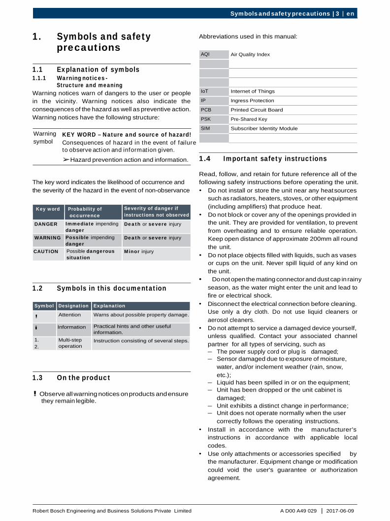
1.6 Enclosure safe handling instructions
Alert type Do's Don'ts No load on hinges Do’s: Always provide support at the bottom side for enclosure cover, in cover open condition to avoid load on hinges.
Don’ts: Do not keep enclosure cover without proper support. Do not keep any load on enclosure cover from inside.
Cotton gloves for product handling Do’s: Always use clean hand gloves to handle the enclosure.
Don’ts: Do not touch the enclosure with bare hands and dirty gloves.
Stacking of enclosures Do’s: Use spacer material (preferably foam) to stack empty enclosure.
Don’ts: Do not stack empty enclosure without any spacer material in-between. Stacking of assembled enclosures are not recommended.
Enclosure movement Do’s: Hold horizontally and ensure support from all the sides during hand carry of enclosures. 4 hands support for larger size (control series) is a must.
Don’ts: Do not hold enclosure in vertical position and hand carry.
Load on vent kits Do’s: Enclosure covers are to be placed at 180° with bottom support.
Don’ts: Do not rest enclosure cover on vent kits. Do not rest enclosure itself on vent kit.
1.7 Short information All efforts have been made to ensure the accuracy of material provided in this document at the time of release. However, the items described in this document are subject to continuous development and improvement. All specifications are subjected to change without notice and do not represent a commitment on the part of Robert Bosch Engineering and Business Solutions Private Limited (RBEI). RBEI will not be responsible for any loss or damages incurred related to the use of information contained in this document.
! Before starting up, connecting and operating this product, it is absolutely essential that the installation instructions and, in particular, the safety instructions are studied carefully. By doing so, any uncertainties in handling this product can be eradicated and will ultimately help to avoid damage to the unit.
Copyright This manual is the intellectual property of RBEI and is protected by copyright. All rights reserved.
Trademarks All hardware and software product names used in this document are likely to be registered trademarks and must be treated accordingly.
Symbols and safety precautions | 5 en
A D00 A49 029 | 2017-06-09 Robert Bosch Engineering and Business Solutions Private Limited
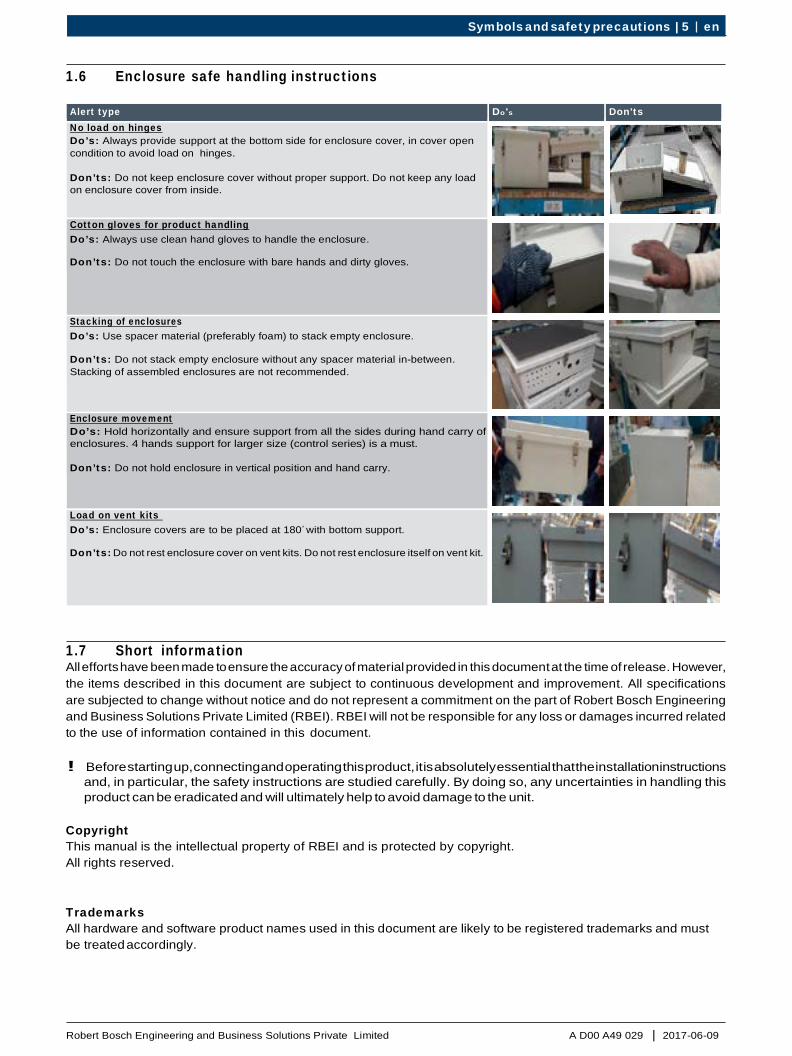
2. BOSCH CLIMO overviewBOSCH CLIMO is designed to measure certain atmospheric gases and factors of the ambient environment.
BOSCH CLIMO features are:
2.1 Version of product
There are four versions of product that is available for customer based on connectivity; • Micro Climate Monitoring System (SC_3G)
A D00 A40 103• Micro Climate Monitoring System (3G)
A D00 A40 100• Micro Climate Monitoring System
A D00 A40 101• Micro Climate Monitoring System (Standard- RJ45)
A D00 A40 102
• It is easy to deploy, technologically advanced and incurs zero added infrastructure investment.
• It connects compact wireless sensors over3G networks enabling micro-climatic data collection.
• BOSCH CLIMO is powered with the state-of-the-art IoT-friendly Intel Quark processor enabled with a “pattern matching” technology; facilitating energy- efficiency, scalability and sustainability for real-world applications.
i Whilst robust in design, the unit is a sensitive piece of scientific equipment and should be treated as such.
! The device must be protected from strong directsunlight as this will quickly raise the temperature of thedevice beyond its operating range. BOSCH CLIMO unithas been provided with a sun shade guard to protectfrom the effects of sunlight.
i Mount the unit facing North or South direction
! There will be variation in sensor behavior due tolimitation of NO, NO2, and O3 sensors on highertemperature range beyond 40°C and PM sensor forbelow -10°C.
2.2 Applications • Real Estate and Community: BOSCH CLIMO will
be the indicator for quality of life index and thebreathability of the ambient air. The recommendationsand early warning system based on air profiling willhelp the society to make smarter choices.
• Smart Cities: It will form a mandatory component forany smart city as it aides in awareness and better citymanagement.
• Industries Construction: It assists in perimetermonitoring of the site, measure the factory healthand determines the condition in which the workersare working.
• Mining and Oil and Gas: This is a heavily pollutingsector by the nature of the industry itself. BOSCHCLIMO will help in compliance adherence by constantmonitoring and thus making it a greener sector.
2.3 Site & Parameter selection as per CPCB guidelines on measurement of Ambient Air Pollutants (Air Quality)
Site Selection
• Away from source & other interferences (inlet 15maway from source/traffic artery).
• Height of inlet >3m (preferably 3-10m) Double theheight of nearby wall/obstructed.
• Free flowing, well mixed.• Elevated angle <30 (from inlet to top of building).• Collocated samplers should be 2m apart.
Parameter Selection
• Sensitive location (SO2 & NO2).• Health Impact stations (All pollutants).• Population & exposure (All criteria pollutants).• Kerb side (Traffic intersection) (criteria pollutants +
CO).• Downtown (Accumulative, 50 m away traffic
intersection) (criteria pollutants + O3).
en 6 | BOSCH CLIMO overview
A D00 A49 029 | 2017-06-09 Robert Bosch Engineering and Business Solutions Private Limited
|
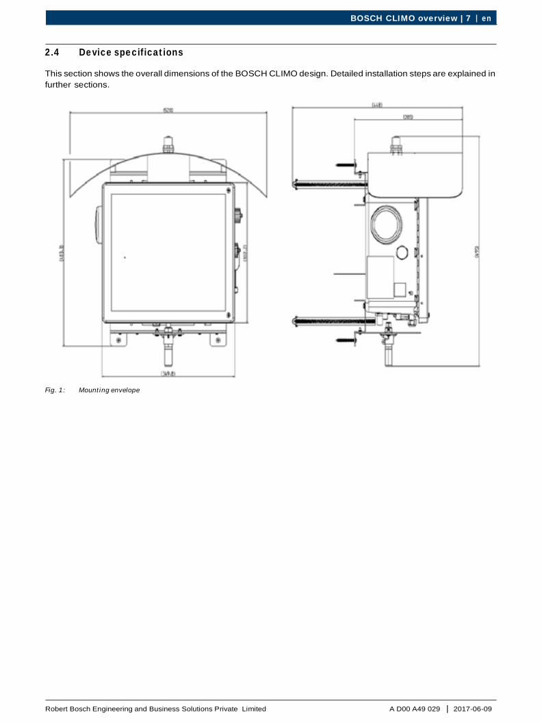
2.4 Device specifications
This section shows the overall dimensions of the BOSCH CLIMO design. Detailed installation steps are explained in further sections.
Fig. 1: Mounting envelope
BOSCH CLIMO overview | 7 en

A D00 A49 029 | 2017-06-09 Robert Bosch Engineering and Business Solutions Private Limited
2.5 Technical data The unit has the following features: Category Features Range Resolution / Remarks
Gas Sensors
Particulate Matter PM 2.5 0 – 500 µg/m³ ± 5 µg/m³ Particulate Matter PM 10 0 – 1000 µg/m³ ± 5 µg/m³ Carbon Monoxide (CO)* 0 – 31000 ppb 100 ppb Nitrogen Dioxide (NO₂ )* 0 – 300 ppb 10 ppb Ozone (O₃ )* 0 – 400 ppb 10 ppb Sulphur Dioxide (SO₂ )* 0 – 700 ppb 10 ppb Nitric Oxide (NO)* (Optional) 0 – 300 ppb 10 ppb
External Mount Sensors (Optional)
CO2 0 – 5% (5000PPM) UV up to 15 UVI
Environmental Sensors
Humidity 10% – 95% RH Temperature -40°C – +70°C
Sound 45dBA – 100 dBA Light up to 188000 Lux Pressure 500 to 1500 mB (hPa)
Connectivity WCDMA/3G WCDMA/3G
Ethernet 10/100 baseT USB 2.0
Physical Attributes
Ruggedness IP 53 High durability, ingress and shock protection
Power supply 100VAC – 240VAC, 50-60 Hz or 9 – 12 V DC
Maximum power rating 20W Ambient Operating Temperature -20°C – +50°C
Humidity 15% – 85% RH Enclosure UV stabilized industrial housing molded
fiberglass reinforced polyesterColor RAL 7035 light gray System weight < 6 kgs Dimension (L x W x H) L 30cm x W 25cm x H 15cm Compact housing Certifications 3G & Ethernet version CE and FCC certified.
PTCRB (is pending) UL Certificate Number 20170731-E492562
Warranty 1 year
Software
Cloud Connectivity or Infra Optional API Interface OTA update Data uplink rate to cloud Configurable (1 Min to 1 Hour) Device Management Clients and Universality Data backup Configurable up to 5 days Remote monitoring, fault detection and self-diagnosis
External Interfaces / add-on accessories
Mounting Pole or Wall mount Splash guard and Sun shade Battery power pack DC power provisions Optional external battery
(12V/40Ah/36W)Solar power pack 12V DC power from Solar panel Optional
en 8 | BOSCH CLIMO overview
A D00 A49 029 | 2017-06-09Robert Bosch Engineering and Business Solutions Private Limited
|
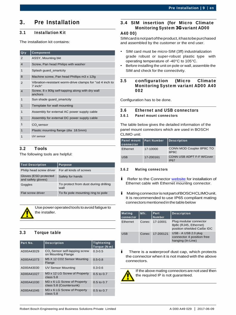
3. Pre Installation3.1 Installation Kit
The installation kit contains:
3.4 SIM insertion (for Micro Climate Monitoring System 3G variant AD00
A40 00) SIM card is not part of the product, it has to be purchased and assembled by the customer or the end user.
• SIM card must be micro-SIM (3ff) industrializationgrade robust or super-robust plastic type withoperating temperature of -40°C to 105°C.
• Before installing the unit on pole or wall, assemble theSIM and check for the connectivity.
3.2 Tools The following tools are helpful:
Tool Description Purpose Philip head screw driver For all kinds of screws Gloves (ESD protected and safety gloves)
Safety for hands
Goggles To protect from dust during drilling wall
Flat screw driver To fix pole mounting ring to pole
Use power operated tools to avoid fatigue to the installer.
3.3 Torque table
3.5 configuration (Micro Climate Monitoring System variant AD00 A40 002
Configuration has to be done.
3.6 Ethernet and USB connectors 3.6.1 Panel mount connectors
The table below gives the detailed information of the panel mount connectors which are used in BOSCH CLIMO unit: Panel mount connector
Part Number Description
Ethernet 17-10000 CONN MOD Coupler 8P8C TO 8P8C
USB 17-200161 CONN USB ADPT F-F W/Cover IP67
3.6.2 Mating connectors
i Refer to the Connector website for installation of Ethernet cable with Ethernet mounting connector.
i Mating connector is not part of BOSCH CLIMO unit. It is recommended to use IP65 compliant mating connectors mentioned in the table below
Mating connector
Mfr. Part Number
Description
Ethernet Conec 17-10001 Plug modular connector 8p8c (RJ45, Ethernet) position shielded Cat5e IDC
USB Conec 17-200121 USB - A USB 2.0 plug connector 4 position free hanging (In-Line)
i There is a waterproof dust cap, which protects the connector when it is not mated with the above connectors.
If the above mating connectors are not used then the required IP is not guaranteed.
Pre Installation | 9 en
Qty Component 2 ASSY, Mounting bkt 4 Screw, Pan head Philips with washer 1 Splash guard_smartcity 8 Machine screw, Pan head Phillips m3 x 12lg 2 Vibration-resistant worm-drive clamps for "od 4 inch to
7 inch"4 Screw, 8 x 80lg self-tapping along with dry wall
anchors1 Sun shade guard_smartcity 1 Template for wall mounting 1 Assembly for external AC power supply cable 1 Assembly for external DC power supply cable 1 CO2 sensor 1 Plastic mounting flange (dia 18.5mm) 1 UV sensor
Part No. Description Tightening Torque (N-m)
AD00A43029 CO2 Sensor self-tapping screw on Mounting Flange
0.3-0.5
AD00A41073 M5 X 12 CO2 Sensor Mounting Flange
0.5-0.8
AD00A43030 UV Sensor Mounting 0.3-0.6 AD00A41027 M3 x 12 LG Screw of Property
class 5.80.5 to 0.7
AD00A41030 M3 x 6 LG Screw of Property class 5.8 (Countersunk)
0.5 to 0.7
AD00A41045 M3 x 6 LG Screw of Property class 5.8
0.5 to 0.7

A D00 A49 029 | 2017-06-09 Robert Bosch Engineering and Business Solutions Private Limited
3.7 Calibration The gas sensors that are available as part of the BOSCH CLIMO are pre-calibrated by the sensor manufacturer and should have expected response to change in ambient air conditions within the first 7 days, post installation. However, these gas sensors are known to drift over time. Hence they require frequent recalibration. BOSCH CLIMO uses the following 2 methods for recalibration: • Regular recalibration cycles or field recalibration: This is done by using data from an EPA graded instrument,
co-located along with or available in the near vicinity of the BOSCH CLIMO. This recalibration is handled remotely using the remote device management platform.
• In-house recalibration: This is carried out by unmounting the device and recalibrating it in a laboratory environment with NIST certified calibration gases or completely replacing the sensor to have a new one in place of the existing one.
i For use cases which require greater accuracy of data, frequent recalibration would be required. The best suited recalibration cycle can be defined by observing the trend of sensor data from the BOSCH CLIMO in its current deployment location for the first few days.
i Environment and particulate matter sensors do not exhibit any behavioral drift over time and hence may not
need regular recalibration cycles.
3.8 Health indicators You can know the device is functional by checking the red LED indicator. Blinking of this LED, indicates that there is a proper connection of the BOSCH CLIMO device with cloud and the data is being transmitted successfully.
3.9 Pre installation Acceptance checklist
i Take the print out of the checklists, sign and store it for every unit.
Sl. No. Description Test Passed (Yes/No/NA)
Comments
1 Availability of product handling or installation safety precaution (ex. hand gloves, ladder, helmet, safety belt)
2 Availability of ESD protection for SIM installation 3 Device Serial number 4 Device Mac ID 5 Location 6 Latt and Long 7 SIM card number 8 SIM ID Number 9 SIM must be industrial grade and WCDMA/3G MICRO SIM (3ff) (Micro-SIM
(3ff) industrialization grade robust or super-robust plastic type with operating temperature -40 ˇ c to 105 ˇ c)
10 Availability of Ethernet mating connector along with cable 11 Availability of Ethernet connection at location 12 Confirmation of signal strength from Service provider at the installation
location 13 Availability and verification of dispatch checklist 14 Physical verification of the complete product and accessory kit 15 Test report available 16 Torque controlled Tools availability for installation 17 Installation manual (soft copy) 18 Availability of DC/AC power socket 19 Ensure the proper voltage (12v DC/230v ac) 20 Ensure no obstruction in north and south direction at the installation pole 21 Installation height must be within 8 to 12 feet 22 Date and time of installation
en 10 | Pre Installation

A D00 A49 029 | 2017-06-09Robert Bosch Engineering and Business Solutions Private Limited
|
3.10 Post installation Acceptance checklist
Sl. No. Description Test Passed (Yes/No/NA)
Comments
1
Torque measurement and record of the mounting - Mounting bracket- Splash guard- CO2 Sensor assembly- UV sensor assembly- Solar Shade
2 Ensure mating connectors and dust caps should be in locked condition 3 Connection details (Ethernet/3G) 4 Switch on the unit and observe blinking of the red LED 5 Ensure the device updating the data on the cloud verified by customer
using their system6 Picture of installation in four direction
7
Details of the four direction at the location North East West South
Pre Installation | 11 en

A D00 A49 029 | 2017-06-09 Robert Bosch Engineering and Business Solutions Private Limited
4. Installation The right behaviour of BOSCH CLIMO unit depends on a reliable installation. RBEI provides the necessary accessories to make it easier, like mounting bracket, screws, connectors, and other accessories.
Wherever BOSCH CLIMO unit is placed, make sure that you tight it firmly and the enclosure is not affected by wind, vibrations and other environmental conditions. RBEI does not take responsibility of damages caused due to tampering or bad installation.
! During the process of unpacking, installing, assembly and servicing, all relevant ESD precautions must be undertaken and handled with care in order to avoid damage and accident.
! Ensure to place the unit on the table that is sturdy
and use soft cover that will not damage the unit.
4.1 Unpacking 1. Detach the upper box from the outer carton
package. 2. Remove the unit from the box carefully and verify
whether there is any damage or not on the unit, during transporting.
3. Open the carton box of the installation kit. 4. Check the delivery carefully to make sure that all parts
have been delivered. If there is any mistake, please contact your authorized dealer at once.
Fig. 2: Packaging
i In the installation kit, parts for both wall mounting and
pole mounting are available.
i Keep the original package for the future transporting.
4.2 Installing SIM To install SIM in the unit:
! Ensure to take necessary ESD precautions during
inserting and removing the SIM card. i Do not insert or remove the SIM card while the unit
is plugged to power supply.
1. Unscrew the two screws.
i Do not remove the screws from the cover panel.
2. Locate the SIM card carrier in the Processor Board. 3. Slide the metal cover of the SIM card holder towards
the back of the box to unlock. 4. Insert the SIM card into the slot and slide the metal
cover to its original position.
Fig. 3: SIM card in the unit
5. Tighten back the screws of the cover panel.
4.3 Mounting bracket assembly To mount bracket to the unit: 1. Place the unit on the table. 2. Fix the mounting bracket to the rear side of the
unit with the screws provided (M5 x 12LG 4Nos “AD00A41031”).
i The surface on which the unit is placed should be
smooth and soft, such that the unit is not damaged,
Fig. 4: Mounting bracket fixed to unit
en 12 | Installation

A D00 A49 029 | 2017-06-09 Robert Bosch Engineering and Business Solutions Private Limited
|
4.4 Pole mounting
To pole mount the unit:
1. Insert the provided vibration-resistant worm-drive clamps, to the mounting bracket slots.
2. Wrap the clamps around the pole.
i The pole mounting clamp provided in the installation kit suits for “5 inch to 6 inch” diameter. If the pole diameter is outside this limit, the installer or user should take care of the mounting clamp.
Fig. 5: Pole mounting
3. Tighten the hexagonal bolt with respect to the pole. i Assemble worm-drive clamps to the mounting bracket
before assembling Sun shade and Splash guard.
i Fix the unit on a flat wall, otherwise mounting of splash guard could be difficult and RBEI will not be responsible for the damage caused.
Fig. 6: Wall mounting
4.6 Sun shade and UV sensor assembly
To assemble sun shade and UV sensor on the unit:
i Sun shade has to be assembled when the unit is mounted on pole or wall. This is needed as space is required to fix the screw through the mounting bracket.
1. Fix the UV sensor on the sun shade from bottom first, 4.5 Wall mounting
To wall mount the unit:
1. Use the wall mounting template to mark out the four mounting holes on the wall.
2. Drill holes on the marked points of the wall. i The mounting holes should be such that it can
accommodate the proposed wall plugs and screws.
3. Insert the supplied mounting plugs into the mounting holes.
4. Fix the unit to the wall with self-tapping screw that is provided, to securely mount the unit to the surface.
5. Fasten the screws. i Use the screws provided, for the unit to be safe on
wall. i Any screws and wall plug can be used that is suitable
for the hole provided in the mounting bracket.
i Fix the splash guard, after the unit is fixed on the wall.
and lock nut on top. 2. Fix the sun shade on to the top mounting bracket with
the provided screws. 3. Connect the USB mating connector.
! Take care not to apply excess load while installing the sun shade, as the unit is not a load carrying component and can cause damage.
! Do not rest the unit on sun shade.
i While assembling handle UV sensor with care.
Fig. 7: Sun shade with UV sensor
Installation | 13 en

A D00 A49 029 | 2017-06-09 Robert Bosch Engineering and Business Solutions Private Limited
4.7 Splash guard and CO2 sensor assembly
To assemble splash guard and CO2 sensor on the unit:
i Splash guard has to be assembled when the unit is mounted on wall. This is needed as space is required to fix the screw through the mounting bracket.
i Avoid installing any other equipment around sensors
(CO2 & UV sensors).
1. Assemble the CO2 sensor, and plastic mounting flange with self tapping screw.
2. Fix it to the Splash guard with the provided M5 screws. 3. Fix the Splash guard to the bottom mounting bracket
with help of provided screws.
! Take care not to apply excess load while installing the splash guard, as the unit is not a load carrying component and can cause damage.
! Do not rest the unit on splash guard.
i While assembling handle, CO2 sensor with care and avoid installing any other equipment around the sensor.
Fig. 8: Splash guard with CO2 sensor
4.8 AC DC connection
To connect AC or DC cable to the unit:
1. When the unit is assembled either on pole or wall, check that the unit is in perfect condition and without any damage.
2. Fix the AC or DC cable harness as per the label indicated on the unit.
Fig. 9: Notch for mating connector
3. Insert the mating connector keeping notch as
reference. i Mating connector should be in unlock position and
inserted completely as shown in the figure below.
Fig. 10: Mating connector insertion
4. Lock the mating connector.
i Carefully insert the connector into the notch with a gentle push and it should not give crunch sound. Smooth lock should happen.
Fig. 11: Mating connector locked
en 14 | Installation
A D00 A49 029 | 2017-06-09Robert Bosch Engineering and Business Solutions Private Limited
|
i In the accessory kit, a separate compatible AC and DC connectors are available with a cable length of around 3m. Before assembling the unit, the other end of the cable has to be assembled to a power socket which is not part of the accessory kit.
1. Based on the power socket on the other end of thecable, fix the necessary plug and connect to powersocket. Switch ON the unit and check if the unit isworking.
i A red glow of the LED indicates that the unit is ON and working.
5. User Interface
application or as part of a customer specific enterprise platform.
These content rich visual displays helps to understand not only the device location and status (online or offline or error prone, etc.) but also, view the instantaneous value of sensor data. The Air Quality Index (AQI) parameter, usually displayed prominently in all these applications, is an important element to understand the overall ambient air conditions within specific geographical boundaries. The AQI is calculated by the analytics platform on the cloud and is based on the incumbent of air quality regulations in the region of deployment. The APIs also allow construction of intuitive dashboards to represent the trend of data over time thereby providing an understanding of changing atmospheric conditions in relation to seasonal or specific events. These applications also generate, customized reports for offline analysis
5.1 Air Quality Index which can aid planning of corrective actions to make the ambient air safer.
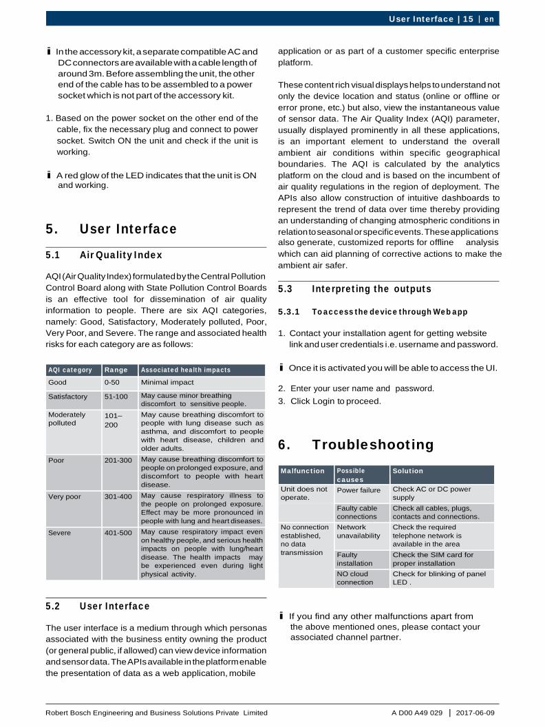
AQI (Air Quality Index) formulated by the Central Pollution Control Board along with State Pollution Control Boards is an effective tool for dissemination of air quality information to people. There are six AQI categories, namely: Good, Satisfactory, Moderately polluted, Poor, Very Poor, and Severe. The range and associated health risks for each category are as follows:
AQI category Range Associated health impacts Good 0-50 Minimal impact Satisfactory 51-100 May cause minor breathing
discomfort to sensitive people.Moderately polluted
101–200
May cause breathing discomfort to people with lung disease such as asthma, and discomfort to people with heart disease, children and older adults.
Poor 201-300 May cause breathing discomfort to people on prolonged exposure, and discomfort to people with heart disease.
Very poor 301-400 May cause respiratory illness to the people on prolonged exposure. Effect may be more pronounced in people with lung and heart diseases.
Severe 401-500 May cause respiratory impact even on healthy people, and serious health impacts on people with lung/heart disease. The health impacts may be experienced even during light physical activity.
5.2 User Interface
The user interface is a medium through which personas associated with the business entity owning the product (or general public, if allowed) can view device information and sensor data. The APIs available in the platform enable the presentation of data as a web application, mobile
5.3 Interpreting the outputs
5.3.1 To access the device through Web app
1. Contact your installation agent for getting websitelink and user credentials i.e. username and password.
i Once it is activated you will be able to access the UI.
2. Enter your user name and password.3. Click Login to proceed.
6. TroubleshootingMalfunction Possible
causesSolution
Unit does not operate.
Power failure Check AC or DC power supply
Faulty cable connections
Check all cables, plugs, contacts and connections.
No connection established, no data transmission
Network unavailability
Check the required telephone network is available in the area
Faulty installation
Check the SIM card for proper installation
NO cloud connection
Check for blinking of panel LED .
i If you find any other malfunctions apart from the above mentioned ones, please contact your associated channel partner.
User Interface | 15 en

A D00 A49 029 | 2017-06-09 Robert Bosch Engineering and Business Solutions Private Limited
7. MaintenanceAlthough BOSCH CLIMO unit is highly resistant to external environment and load, periodic maintenance and care of
i Periodic maintenance is required for all the sensor probes like particle matter sensor, temperature and humidity, UV sensor and CO2 sensor to ensure accurate readings.
the unit is required for a longer useful life. 8.1 Disposal
• Handle BOSCH CLIMO unit with care duringinstallation, transportation and maintenance.
• While transporting the unit, proper packaging needsto be taken care.
• Avoid placing the unit in place where there is chanceof reaching high temperatures, this could damage theelectronic components.
• The locknut of connectors are gentle, do not applyexcessive force upon installing or it may get damaged.
• CO2 and UV sensors are highly sensitive and extra careis required for assembly handling and storage.
• Do not use any type of paint on the device, it coulddeteriorate the properties.
• Do not use aggressive chemical products for cleaning, .
i Gas sensors may require replacement for optimal accuracy. The periodic replacement depends on the location at which the unit is installed.
i Automatic system notification is sent to the administrator, whenever the maintenance is required.
8. RecommendationsRBEI gives some recommendations to improveperformance and efficiency of BOSCH CLIMO unit,enlarging useful life of all of its elements.• Keep the unit and its sensors out of direct sunlight
and glare. It is known that, sun rays accelerates plasticelements deterioration.
• BOSCH CLIMO unit is waterproof (rated at IP53).Extra precautions are taken to protect the unit againstmost weather conditions, however make sure that thewater does not enter the unit directly. If your modelincludes external solar panel, it is recommended toplace the unit under the solar panel, to keep the nodeout of the rain. Ensure that the solar panel is facedto south (north if you are on the south hemisphere)and tilted 45º.
• Always place the unit such that the connectors andantenna face towards either to west or east.
• Keep the unit out of range of people who can damageinstallation, wet sensors, etc.
• As per sensor manufacturer’s specification, sensorsare capable of producing accurate data under stabletemperature & humidity. The standard test conditionsare 20°C and 80% RH and in the absence of interferinggases.
• RBEI takes no responsibility of any damage to thirdparties caused by a bad installation.
Disposal - Your Bosch product was
developed and manufactured with high-quality material and components that can be recycled and reused. This symbol means that electronic and electrical appliances, which have reached the end of their working life, must be collected and disposed of separately from household waste material. Separate collecting systems are usually in place for disused electronic and electrical products. Please dispose of these units at an environmentally compatible recycling facility, as per the law of the land.
! Hand over the old/discarded electronic equipmentonly to authorized collection centers for disposal.
See also: Contact No: 180042535287 (toll-free) E-mail: [email protected] website: www.ewasteindia.com
9. Warranty• This unit is guaranteed, to the original end user
purchaser, against defect in materials andworkmanship for a period of 12 months from thedate of the shipment to the user. During this periodBosch will repair or replace defective parts on anexchange basis. The decision to repair or replace willbe determined by Bosch.
• To maintain this warranty, the purchaser must performthe installation and maintenance as prescribed inthe manual. Only the parts supplied by Bosch shouldbe fitted. Normal wear and tear, and parts damagedby abuse, misuse, negligence, or accidents arespecifically excluded from the warranty.
• Exposure to temperature outside the range of -20°Cto +50°C (with clause for PM sensor, NO, NO2 and O3
sensor) or to relative humidity outside the range of15% to 85% will void the warranty.
en 16 | Maintenance

A D00 A49 029 | 2017-06-09Robert Bosch Engineering and Business Solutions Private Limited
|
10. FCC Warning statement15.19
• This device complies with Part 15 of the FCC Rules.Operation is subject to the following two conditions:
1. This device may not cause harmful interference, and2. This device must accept any interference received,
including interference that may cause undesiredoperation.
• Any changes or modifications not expressly approvedby the party responsible for compliance could void theauthority to operate equipment.
• This device and its antenna must not be colocated oroperating in conjunction with any other antenna ortransmitter.
• End-users and installers must be provided withantenna installation instructions and transmitteroperating conditions for satisfying RF exposurecompliance.
• For product available in the USA/Canada market, onlychannel 1~11 can be operated. Selection of otherchannels is not possible.
11. FCC Warning statement15.105
This equipment has been tested and found to comply with the limits for a Class B digital device, pursuant to part 15 of the FCC Rules. These limits are designed to provide reasonable protection against harmful interference in a residential installation. This equipment generates, uses and can radiate radio frequency energy and, if not installed and used in accordance with the instructions, may cause harmful interference to radio communications. However, there is no guarantee that interference will not occur in a particular installation. If this equipment does cause harmful interference to radio or television reception, which can be determined by turning the equipment off and on, the user is encouraged to try to correct the interference by one or more of the following measures:
• Reorient or relocate the receiving antenna.• Increase the separation between the equipment and
receiver.• Connect the equipment into an outlet on a
circuit different from that to which the receiver isconnected.
• Consult the dealer or an experienced radio/TVtechnician for help.
12. Statement
i Any changes or modifications not expressly
approved by the party responsible for compliance could void the authority to operate equipment.
i This device and its antenna must not be co-located
or operating in conjunction with any other antenna or transmitter.
i End-users and installers must be provided with
antenna installation instructions and transmitter operating conditions for satisfying RF exposure compliance.
13. Mobile DeviceThis equipment complies with FCC radiation exposure limits set forth for an uncontrolled environment. This equipment should be installed and operated with minimum distance 20cm between the radiator & your body.
14. RED Requirement• Ensure that the equipment can operate in at least
one Member State. “The radio equipment can be used in one member state at least”
• CE mark• A copy DoC / simplified DoC which shall accompany
the product– Copy of DoC is made available to user.
http://35.157.28.63/app/index.html#/login
FCC Warning statement 15.19 | 17 en

Robert Bosch Engineering and Business Solutions Private Limited 123, Industrial Layout, Hosur Road, Koramangala, Bangalore 560 095 INDIA