Embed Size (px)
Citation preview
MICHIGAN DEPARTMENT OF TRANSPORTATIONMDOT
Design Procedures for Concrete Anchors(Mechanical Expansion and Bonded Anchors)
Douglas NeedhamDavid A. Juntunen, P.E.
Testing and Research SectionConstruction and Technology Division
Research Project 94 TI-1707Research Report No. R-1361
Michigan Transportation CommissionBarton W. LaBelle, Chairman;
Jack L. Gingrass, Vice-Chairman;Robert M. Andrews, John C. Kennedy,
Betty Jean Awrey, Ted B. WahbyJames R. DeSana, Director
Lansing, June 1998

ACKNOWLEDGMENTS
Although many people participated in this project, space and memory will notallow a complete list of everyone’s involvement. However, the following peopleshould be mentioned; Roger Till for project guidance, Larry Pearson, Chris Davisand all other people who were part of the Structural Research Unit while thisproject was ongoing.
TABLE OF CONTENTS
Introduction . . . . . . . . . . . . . . . . . . . . . . . . . . . . . . . . . . . . . . . . . . . . . . . . . . . . . . 1
General Characteristics . . . . . . . . . . . . . . . . . . . . . . . . . . . . . . . . . . . . . . . . . . . . . 1
Design Philosophies . . . . . . . . . . . . . . . . . . . . . . . . . . . . . . . . . . . . . . . . . . . . . . . . 3
Detailed Design Procedures for Anchorages in Hardened Concrete . . . . . . . . . . . 3
Conclusion . . . . . . . . . . . . . . . . . . . . . . . . . . . . . . . . . . . . . . . . . . . . . . . . . . . . . . . 7
Recommendations . . . . . . . . . . . . . . . . . . . . . . . . . . . . . . . . . . . . . . . . . . . . . . . . . 8
References . . . . . . . . . . . . . . . . . . . . . . . . . . . . . . . . . . . . . . . . . . . . . . . . . . . . . . . 9
Figures . . . . . . . . . . . . . . . . . . . . . . . . . . . . . . . . . . . . . . . . . . . . . . . . . . . . . . . . . 10
Appendix A - H . . . . . . . . . . . . . . . . . . . . . . . . . . . . . . . . . . . . . . . . . . . . . . . . . . 16
-1-
INTRODUCTION
Concrete anchors are often used to make attachments to the concrete surfaces of bridges and highwaybarriers. Various department publications provide quality control and guidance so these anchors aresafe, efficient, and economical. During this study, the Structural Research Unit reviewed thedepartment’s procedures and specifications for designing and accepting two types of concreteanchors, mechanical expansion anchors and bonded anchors. We studied design procedures ofvarious national codes, design guides, and research publications. We also collected and reviewednumerous manufacturers’ recommendations, product data, and installation procedures.
This report provides clarification and instruction to designers as to the proper design and use ofconcrete anchors. In the following sections, we discuss general characteristics of concreteanchorages, design philosophies, and detailed design procedures for each type of anchor. In addition,we provide recommendations for changes to the Michigan Design Manual-Bridge Design, Volume5 (design manual) and the 1996 Standard Specifications for Construction.
During the scope of this report, we did not evaluate either of the anchor types (mechanical expansionor bonded) for creep. Therefore, until further research is performed, designers should avoid usingpost installed concrete anchors for connections requiring sustained loading.
Undercut anchors were also beyond the scope of this report.
GENERAL CHARACTERISTICS
The American Concrete Institute (ACI) provides a good reference for concrete anchors inReport 355.1R-91, State-of-the-Art Report on Anchorage to Concrete. This ACI report discussescast-in-place anchorages as well as anchorages to existing concrete structures (post-installedsystems). For the latter type, the department allows two types of anchoring systems, mechanicalexpansion anchors and bonded anchors. The following sections briefly describe each system.
Mechanical Expansion Anchors
The department allows three types of mechanical expansion anchors: stud, drop-in, and self-drilling.All three work by applying force to the sides of a predrilled hole, which in turn prevents pulloutthrough frictional forces developed on the sides of the hole.
The stud mechanical expansion anchor consists of a threaded rod with an expansive device on oneend (refer to Figure 1). This anchor is set by placing it into a predrilled hole and turning the nut tothe recommended torque. The expansive device expands into the side of the hole as the nut istorqued.
The second type of mechanical expansion anchor is the drop-in anchor (refer to Figure 2). Thisanchor is also placed into a predrilled hole, but it is secured with the aid of a setting tool and/or a
-2-
hammer depending on the type of plug, whether it is internal or external. The internal plug is setby driving the plug toward the bottom of the anchor with a setting tool and a hammer. As the plugmoves toward the end of the anchor, the anchor sleeve expands. Similarly, the external plug is setby driving the anchor down around the plug, thus expanding the body of the anchor.
The final type of mechanical expansion anchor is the self-drilling anchor (refer to Figure 3). Theself-drilling anchor attaches to a roto-hammer, which is used to drill the proper size hole. Theanchor and external plug are then inserted into the hole and tightened in the same manner as thedrop-in anchor with an external plug.
Mechanical expansion anchors are preferred in certain situations that require the anchor to sustainimmediate loading. As soon as they are installed, attachments can be made and loads can be applied.This may be advantageous for applications that require traffic control or limited installation time.
Through field experience we found that when mechanical expansion anchors are installed into a holethat intersects rebar, the anchor fails to meet the required load. Mechanical expansion anchors aresensitive to proper installation. The predrilled hole must be round not oblong. If steel reinforcementis encountered when drilling into concrete, the bit travels around the reinforcement creating anoblong hole. This odd shaped hole decreases the required bearing area and in turn decreases theanchor’s load carrying capacity. Designers should avoid using mechanical expansion anchors inheavily reinforced areas to avoid this problem.
Bonded Anchors
The department allows two categories of bonded anchor systems: adhesive anchors and groutedanchors. Adhesive anchors work by creating a chemical bond between the anchor and the concrete.The setting material for adhesive anchors is a two-part (epoxy or polyester) system. Depending onthe type of packaging, the mixing of the resin and hardener occurs either as the material flowsthrough a mixing nozzle or in the predrilled hole as the glass capsule is broken by the rotating anchorrod or rebar. One note about adhesive anchors, there is a gel time and cure time. Gel time refers tothe time until the adhesive initially sets. Cure time is how long the product takes to fully dry andstabilize. Only after the cure time has elapsed can the anchor withstand the desired loading. Groutedanchors work by creating a cement bond between the anchor and the concrete. The setting materialfor the grouted anchor is mixed with potable water and placed into the predrilled hole. As withadhesive anchors, grouted anchors must fully cure before the application of load.
Bonded anchors are preferred in situations that require anchors to be installed next to reinforcingsteel, reinforcement to be post-installed, and/or epoxy coated anchors. Unlike mechanical expansionanchors, bonded anchors can operate properly if the predrilled hole intersects reinforcement. Theadhesive compound/grout flows around the reinforcement, filling all voids between the attachmentand the oblong hole sides. Although mechanical expansion anchors only permit a threaded rod orbolt be inserted into hardened concrete, bonded anchors can be used with either threaded rods, bolts,or deformed reinforcement bars. Finally, bonded anchors are preferred when the design detail callsfor epoxy coated anchors. When installing anchors with the bonded systems, the epoxy coatedanchors will not be damaged. Mechanical expansion anchors require either turning a nut to the
-3-
specified torque or driving a plug into the end to set the anchor, both of which remove the existingepoxy coating.
DESIGN PHILOSOPHIES
There are two philosophies used for designing anchorages into concrete. The first philosophydesigns the anchorage to ensure that the tensile strength of the steel reinforcement is achieved; thistype of anchorage is referred to as a deep embedment. Deep embedments are commonly placed priorto the placement of concrete at a depth deep enough to obtain the required development length.
The second philosophy designs for concrete failure (i.e., shallow embedment). A shallowembedment will crack or spall the concrete prior to developing the tensile strength of the anchor,therefore the strength of the concrete controls the allowable loads.
Post-installed concrete anchors are to be designed for deep embedments (i.e. steel failure). However,through our laboratory experience, we found that most post installed anchoring systems normallyfail prior to the actual yielding of the anchor steel (i.e. they fail as a shallow embedment) eventhough the anchor meets the minimum specified yield point in pullout. This may be due to the factthat the anchor steel tensile yield strength is actually higher than minimum specified. Therefore, theengineer should design for a ductile steel failure and be aware that our laboratory experience hasshown that post-installed anchors may have a brittle failure because the steel has a higher yield pointthan the minimum specified.
DETAILED DESIGN PROCEDURES FOR ANCHORAGES IN HARDENED CONCRETE
When designing for mechanical expansion or bonded anchors, the following publications can beused for design guidance:
• State-of-the-Art Report on Anchorage to Concrete, ACI 355.1R-91, ACI Committee 355,July 1991.
• ACI 349 - Appendix B - Steel Embedments, American Concrete Institute, pp 349-80 to349-86.
Anchors loaded with the combination of tension and shear simultaneously must be evaluated for theload interaction. Therefore, designers must check that the tensile stress and shear stress areproportioned to satisfy the following interaction equation:
In the following sections, acceptance and design procedures are discussed. Design examples areshown for each type of anchor.
-4-
Mechanical Expansion Anchors
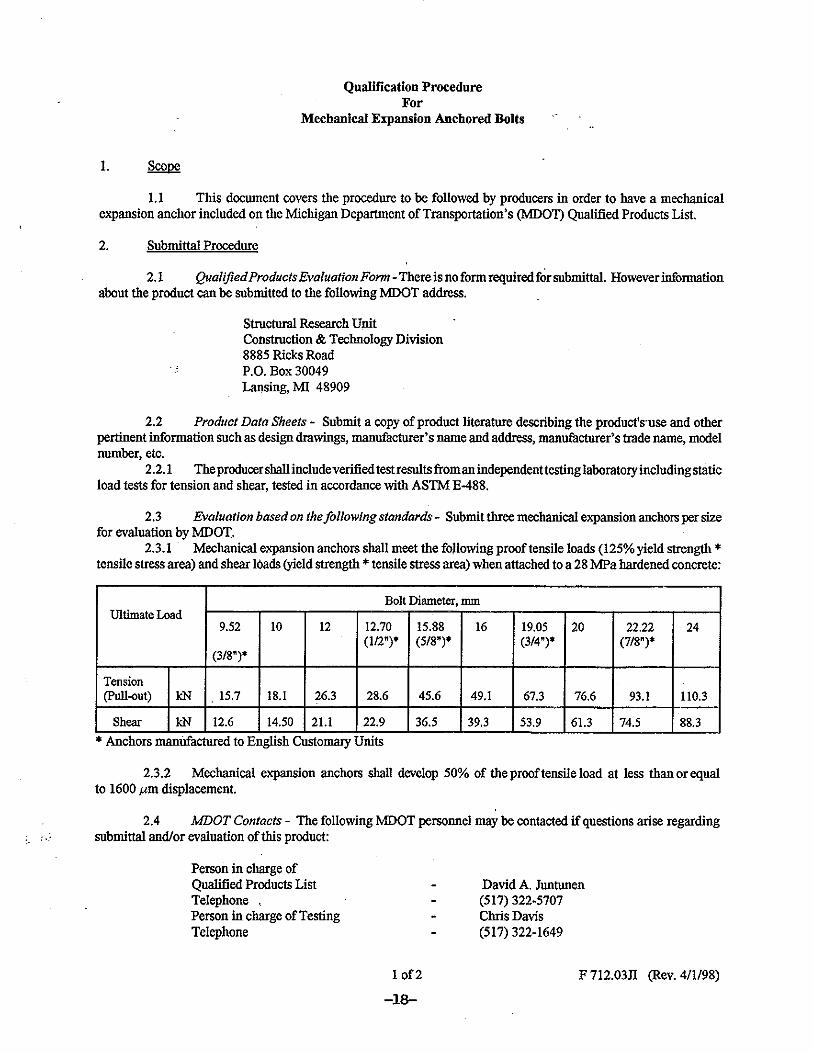
For a mechanical expansion anchor to be used by the department, it must meet the criteria set forthin the Qualification Procedure for Mechanical Expansion Anchored Bolts, which is provided inAppendix A. Each anchor size must be able to develop a required proof tensile load and shear load.The proof tensile loads are 125 percent of the anchor steel’s yield strength applied to the tensilestress area of the bolt (i.e., - net section through the threads). The shear loads are 100 percent of theshear strength of the bolt across the tensile stress area. It should be noted that these values shouldnot be confused with allowable design loads, which are discussed later in this report. Since mostmanufacturers only provide U. S. Customary unit anchors at this time, both metric and U. S.Customary units are shown in the qualification procedure. Some manufacturers have stated thatmetric anchors will be available in the near future. Therefore, when the metric anchors aresubmitted, the Structural Research Unit will investigate and evaluate them.
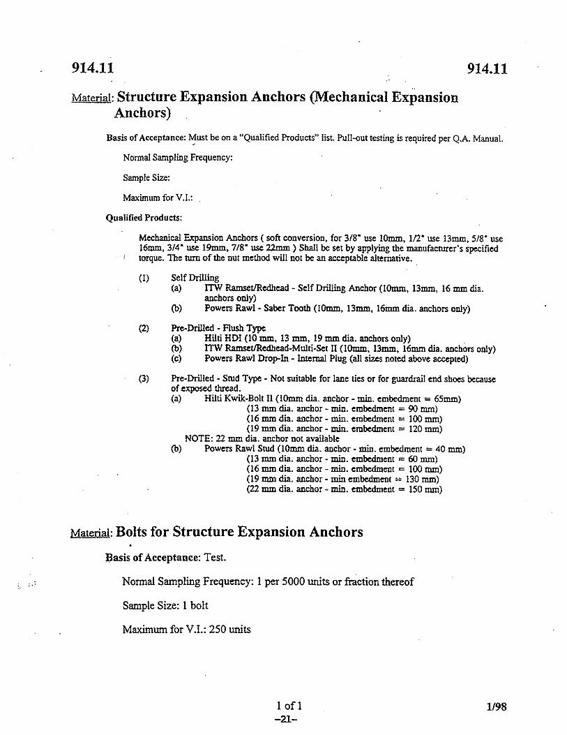
The Qualified Products List for Mechanical Expansion Anchors (included in Appendix B) lists theanchors that meet the department’s qualification procedure. The list has categories for the three typesof anchors; stud, drop-in, and self-drilling. For a stud anchor, the list shows the required minimumembedment depth due to the variety of embedment depths listed by the manufacturer. Theembedment depths for the remaining anchors shall be obtained from the manufacturer’srecommendations. The department provides design guidance for mechanical expansion anchors in the design manual,Subsections 7.06.02 and 8.09.01. During this research project, we discovered the values in thismanual need adjustment to meet our current acceptance criteria and meet the available anchors theindustry has to offer. Subsection 7.06.02 should be revised from the existing section (refer to Figure4) to the proposed section (refer to Figure 5). A commonly used industry standard is to apply afactor of safety of 4 to the proof tensile load of the anchor when determining the allowable designtensile load. ACI 349 Section B.7.2 references a reduction factor of 0.33 times the average tensionand shear test failure loads. This reduction factor can be used as an alternative to the safety factorof 4 when the applied loads are factored in accordance to Subsection 9.2 of ACI 349. For normaltensile design loads, we recommend using a factor of safety of 4, but for vibratory tensile loads asafety factor of 12 should be used. Subsection 7.06.02 C of the design manual (Figure 5) should beadded to inform the designer about allowable shear loads. Figure 6 shows a comparison betweenthe existing Subsection 7.06.02 of the design manual and the proposed section. The allowable loadsfor small diameter anchors have decreased, while the allowable loads for larger diameter anchorshave increased. Also, the non-critical category has been removed. From our experience, mechanicalexpansion anchor bolts begin to slip at approximately 50 percent of the proof tensile load. Becauseof this, and again to be in alignment with industry standards, we removed the non-critical category.Since mechanical expansion anchor bolts are dependent on installation procedures to develop theirstrength and because the performance of these anchors can be variable, redundancy should alwaysbe designed into the system. Therefore, the following note should be added to Subsection 7.06.02of the design manual to ensure safety: “Design details should always call for two or more anchorsfor redundancy.”
Similarly, Subsection 8.09.01 of the design manual should be revised from the existing section (referto Figure 7) to the proposed section (refer to Figure 8). We propose removing the existing Note B.
-5-
Since the testing requirements for mechanical expansion anchors are specified in Subsection712.03.J.2 of the 1996 Standard Specifications for Construction, the existing Note B is redundantand should be removed.
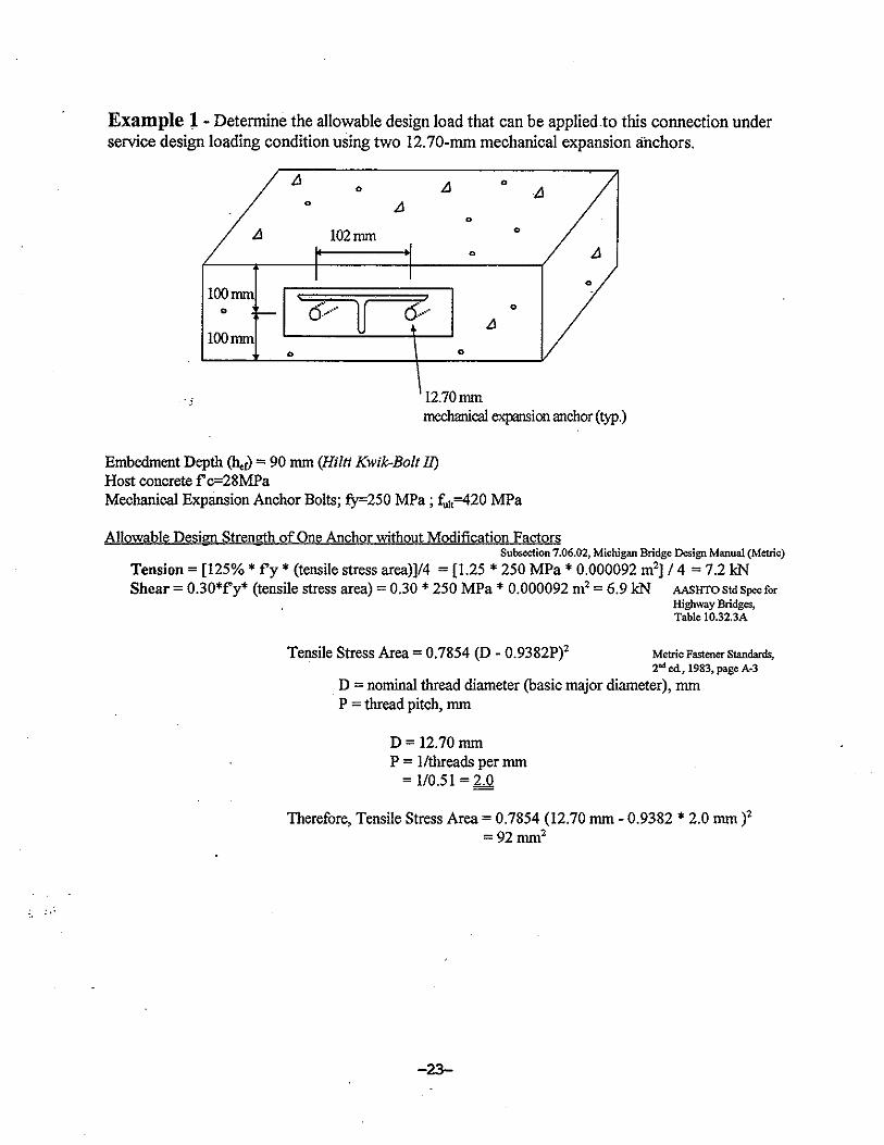
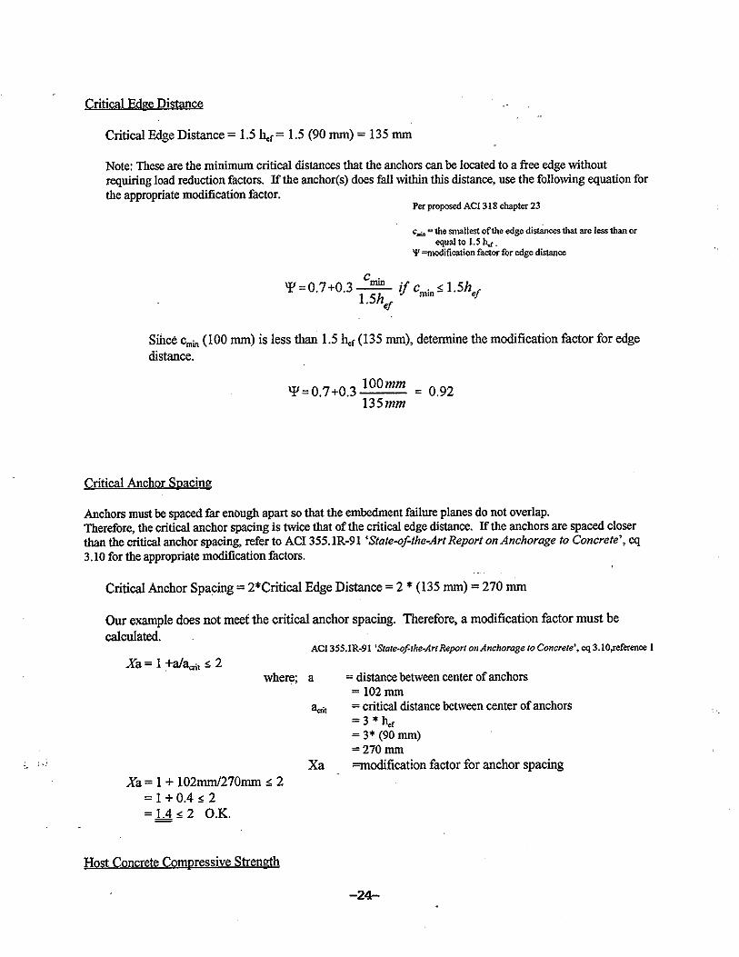
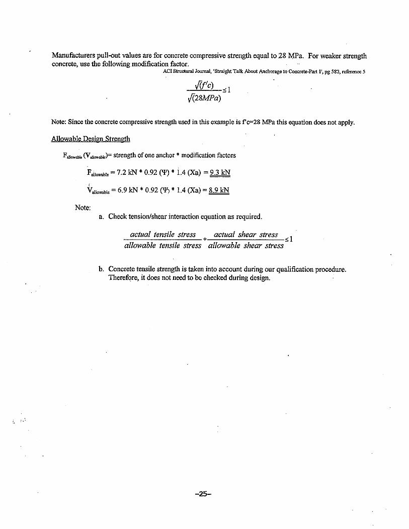
Additional considerations when designing mechanical expansion anchors are: installation location,condition and strength of the concrete, and strength reduction factors resulting from the edgespacing, anchor spacing, and concrete compressive strength. Guidance is specified in the two ACIpublications, State-of-the-Art Report on Anchorage to Concrete, ACI 355.1R-91, ACI Committee355, July 1991, and ACI 349 - Appendix B - Steel Embedments, American Concrete Institute. Allqualification procedures were established on a concrete compressive strength of 28 MPa. If the hostconcrete compressive strength is less, then the following design strength reduction should be taken�(ƒ/c1)/�(ƒ/c2 ), where ƒ/c2 equals 28 MPa. If the host concrete compressive strength is greater thanthe minimum specified strength, no adjustment shall be made. Refer to Appendix C for amechanical expansion anchor design example.
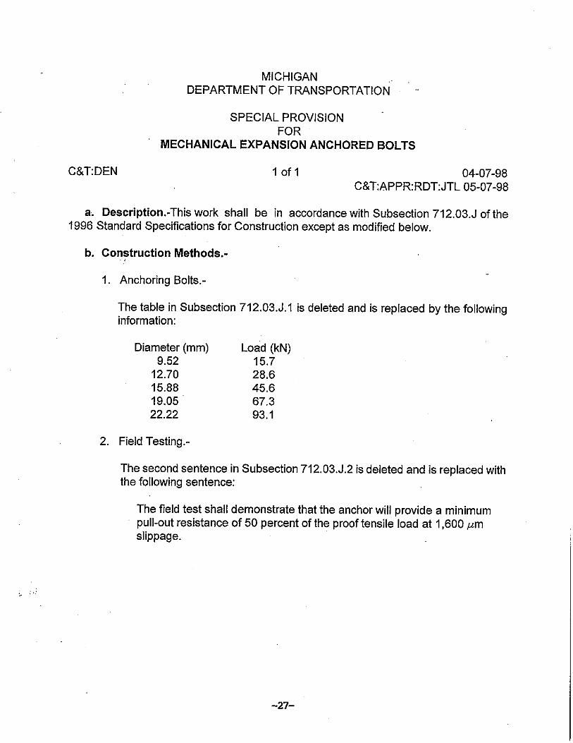
Once the design is completed, the next step is installation. Subsection 712.03.J of the 1996 StandardSpecification for Construction describes the requirements for anchor selection, installation, and fieldtesting requirements. Keeping in line with the previously mentioned changes, proof tensile load andanchor size must be revised. The proof tensile loads along with the anchor diameters need to berevised to reflect the soft conversion of mechanical expansion anchors, and the slip requirementneeds to be revised from 2 mm to 1,600 µm. As revised, the field test shall demonstrate that theanchor will provide a minimum pull-out resistance of 50 percent of the proof tensile load at 1,600µm slippage, not 2 mm slippage. When the initial slip requirement of 800µm was determined, it wasan arbitrary value set for pavement lane ties. For mechanical expansion anchors, we found mostmanufacturers and codes specified load values at 1,600 µm of slip. During our laboratory testing,most of the mechanical anchors did slip 1,600 µm at 50 percent of the proof tensile load. Therefore,we incorporated the manufacturer’s slip requirement of 1,600 µm into our specifications - refer toAppendix D for the Special Provision for Mechanical Expansion Anchored Bolts. Although, it isthe requirement of the contractor to determine the embedment depth and anchor type, designers mustbe familiar with typical hole diameters and depths so they can place the anchors in appropriatelocations. The 1996 Standard Specifications for Construction requires the contractor to use apachometer to locate reinforcing steel so that it will not be cut or interfere with the installation of theanchor.
Bonded Anchors
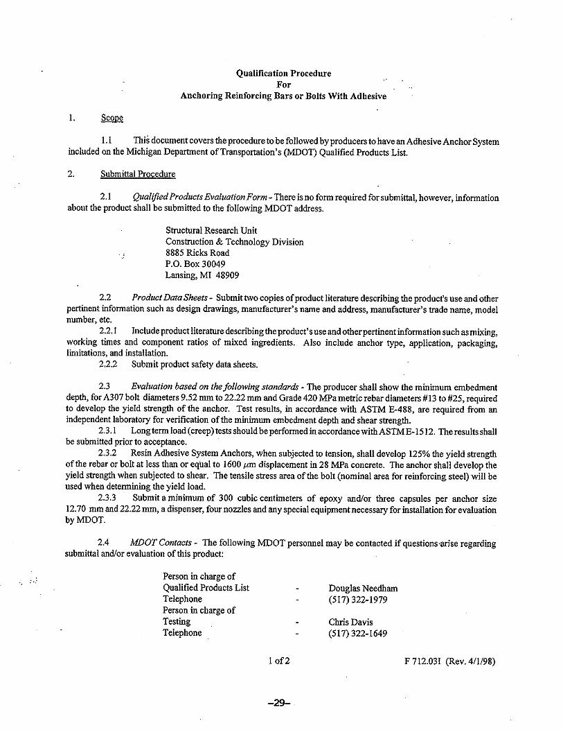
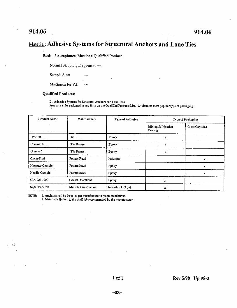
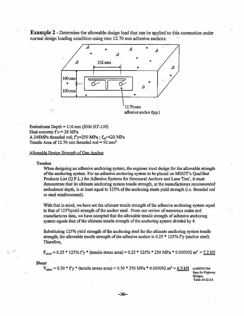
Before a bonded anchor can be used in department projects, it must meet the requirements set forthin the Qualification Procedure for Anchoring Reinforcing Bars or Bolts with Adhesive. Thequalification procedure, included in Appendix E, requires that the pull-out strength of a bondedanchor be greater than 125 percent of the yield strength of an A307 bolt or Grade 420MPa steelreinforcement with less than 1,600 µm slip when installed according to the manufacturer’srecommended minimum embedment depth. Bonded anchors that have met the department’s qualifications are listed in the Qualified ProductsList for Adhesive Systems for Structural Anchors and Lane Ties (refer to Appendix F). To furtherenhance the partnering between the department and the contractors, embedments depths are not listed
-6-
on the qualified products list. Instead, a note is provided stating that the anchors shall be installedper manufacturer’s recommendations.
Bonded anchors are designed for steel failure, even though our laboratory experience has shown thatpost-installed anchors fail prior to the actual yielding of the anchor steel as previously discussed.To obtain the allowable design strength, a safety factor of 4 should be applied to 125 percent of thethreaded rod/reinforcements yield strength. Similar to mechanical expansion anchors, this factor ofsafety of 4 is a common industry standard. The safety factor applies to all situations where a bondedanchor is designed (i.e., non-critical, static or shock loads, and vibratory loads). Subsection7.06.02 B (Figure 5) should be added to the design manual to inform designers of the safety factor.Similar to mechanical expansion anchors, as an alternative design (LRFD), ACI 349 SubsectionB.7.2 can be used with a reduction factor of 0.33 times the required tested load when the loads arefactored in accordance with Subsection 9.2 of ACI 349. Also, Subsection 7.06.02 C of the designmanual (Figure 5) should be added to inform the designer about allowable shear loads.
The current practice for detailing vertically bonded anchors is to state the anchor size, embedmentdepth, and hole size. We propose, due to the variations between bonded anchor embedment depthsand hole diameters, that the department no longer state the required hole diameter nor theembedment depth for a bonded installation, except where noted. As referenced inSubsection 712.03.I of the 1996 Standard Specifications for Construction, “The Contractor shallpropose for the Engineer’s approval, complete details of the drilling, cleaning, and bonding systemsfrom the QPL to be used for anchoring the reinforcement. If hole sizes are shown on the plans, theyare for epoxy mortar adhesive systems.” Therefore, to create consistency between the plans and1996 Standard Specifications for Construction, we recommend that bridge designers discontinuespecifying embedment depths and hole sizes for post-installed concrete anchors, except when usedin concrete barriers due to past problems associated with bottom of deck spalls. A plan note shouldbe added stating, “Concrete anchors shall be installed according to the manufacturer’srecommendations.” However, designers must be familiar with typical hole diameters and depths sothey can place the anchors in appropriate locations.
The design manual provides recommended plan notes for bonded anchors in Subsection 8.09.01.During our investigation, we discovered that Subsection 8.09.01 requires revision. Currently, Note Cstates “Systems for anchoring horizontal (reinforcement) (bolts) in existing concrete shall be eitherHilti HVA or Molly Parabond. (Use only where bar or bolt will be subjected to a sustained load.)”Since neither of these products are currently listed on our current Qualified Products List forAdhesive Systems for Structural Anchors and Lane Ties, the note should be revised to the following:“Systems for anchoring horizontal or vertical (reinforcement) (bolts) in existing concrete shall bechosen from the department’s current Qualified Products List.” In addition to the change in theexisting Note C, an additional note should also be added: “All concrete anchors shall be installedaccording to the manufacturer’s recommendations, unless otherwise stated.” Refer to Figure 7 forthe existing notes and to Figure 8 for the revised notes.
Subsections 6.29.08A and 6.29.09 of the design manual also instruct designers when designing forbonded anchors. This guide, which details bridge barrier railing, Type 5 and Type 4 (modified),specifies the hole diameter and embedment depth for the vertical concrete anchors. Due to pastproblems associated with bottom of deck spalls, these guides should not be altered.
-7-
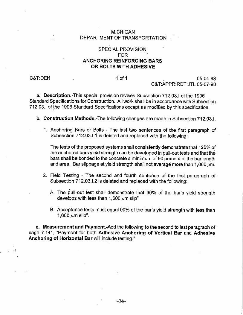
Construction guidance for bonded anchors is given in Subsection 712.03.I of the 1996 StandardSpecifications for Construction. During our investigation, we discovered this subsection requiresmodification. As with the mechanical expansion anchor bolts, the slip requirement should bechanged from 2 mm to 1,600 µm. Therefore, field installed bonded anchors must develop the yieldstrength of the anchor with less than 1,600 µm slip, not 2 mm slip, when tested prior to use. Also,the anchor shall develop 90 percent of the bar’s yield strength with less than 1,600 µm slip, not2 mm slip, when tested is a separate test block. Refer to Appendix G for the Special Provision forBonded Anchors describing these changes.
Additional items designers must consider for bonded anchors are: type and size of the anchor(reinforcement or threaded rod), the installation location, the condition and strength of the concrete,and the strength reduction factors resulting from the edge spacing, anchor spacing, and concretecompressive strength. Guidance is provided in the two ACI publications previously mentioned. Allqualification procedures were established on a concrete compressive strength of 28 MPa. If the hostconcrete compressive strength is less, then the following design strength reduction should be taken�(ƒ/c1)/�(ƒ/c2 ), where ƒ/c2 equals 28 MPa. If the host concrete compressive strength is greater thanthe minimum specified strength, no adjustment shall be made. Refer to Appendix H for a bondedanchor design example. Although designers must provide details that are feasible to build, it is therequirement of the contractor to determine the embedment depth and bonded anchor type.
Conclusion
The department specifies two types of concrete anchors: mechanical expansion and bonded. Bothanchors are intended to be installed in hardened concrete and designed for deep embedments (i.e.yielding of the anchor steel). However, our laboratory experience has shown that post-installedconcrete anchors systems fail prior to the actual yielding of the anchor steel (i.e. they fail as ashallow embedment) even though the minimum specified yield point is met. The brittle failure maybe due to the fact that the anchor tensile yield strength is actually higher than the minimum specified.
Mechanical expansion anchors and bonded anchors must have the appropriate safety factorsspecified in Michigan Design Manual-Bridge Design, Volume 5, Subsection 7.06.02 applied duringdesign. Additional design guidance is provided by the ACI 349 - Appendix B-Steel Embedmentsand the ACI Committee 355 publication, State-of-the-Art Report on Anchorage to Concrete.
There are advantages and disadvantages for each type of concrete anchor system. Advantages thatthe bonded anchors have over mechanical expansion anchors are as follows: they can be installednext to steel reinforcement, they can attach either threaded rod or steel reinforcement to hardenedconcrete, and bars can be epoxy coated. The main advantage that the mechanical expansion anchorhas over the bonded anchor is the set time required before loading. The bonded anchor must be fullycured before the desired load is applied, whereas mechanical expansion anchors can withstand a loadas soon as they are installed.
RECOMMENDATIONS
Design
-8-
1. Design guidance shown in ACI 349 - Appendix B-Steel Embedments, and/or ACI committee355 publication, State-of-the-Art Report on Anchorage to Concrete, should be followed whendesigning mechanical expansion anchors or bonded anchors.
2. Update the Michigan Design Manual-Bridge Design, Volume 5, as stated in this report andas shown in Figures 5 and 8.
3. Add the special provision shown in Appendix D to all proposals that list the pay item, “Bolt,Mechanical Expansion Anchored.”
4. Add the special provision shown in Appendix G to all proposals that list any of the followingpay items: “Adhesive Anchoring of Vertical Bars,” “Adhesive Anchoring of Horizontal Bar,”and/or “Bolt, Adhesive Anchored.”
Structural Research Unit
1. Investigate metric mechanical expansion anchors when submitted.2. Investigate the need for “creep” acceptance criteria for bonded anchors.3. Keep up to date with the latest technology and design methods used for mechanical
expansion anchors and bonded anchors.
-9-
REFERENCES
1. State-of-the-Art Report on Anchorage to Concrete, ACI 355.1R-91, ACI Committee 355,July 1991
2. American Association of State Highway and Transportation Officials, StandardSpecifications for Highway Bridges, 16th ed., Washington, D.C., 1996 Section 8.25
3. ACI 349 - Appendix B-Steel Embedments, American Concrete Institute, pp 349-80 to349-86 and 349R-18 to 349R-27
4. ICBO Evaluation Service, Acceptance Criteria for Expansion Anchors in Concrete andMasonry Elements, January 1993
5. ACI Structural Journal, Straight Talk about Anchorage to Concrete-Part 1, Title 92-S56,Robert W. Cannon, September-October 1995, pp 580-586
6. ICBO Evaluation Service, Acceptance Criteria for Adhesive Anchors in Concrete andMasonry Elements, April 1995

-10-
FIGURES

-16-
APPENDIX