Embed Size (px)
Citation preview

SYSTEM AND SOFTWARE
DESIGN USING THE
UNIFIED MODELING
LANGUAGE (UML)
Michael Weintraub
And
Frank Tip

UNIT OBJECTIVE
Gain perspective on how to think about designing a system
Introduce a graphical way to describe systems
UML
Thanks go to Martin Schedlbauer and to Andreas Zeller for allowing
incorporation of their materials on UML
2

WHY MODEL A SYSTEM?
Helps clarify the requirements
Identifies gaps
Useful tool for understanding how the details really fit in or fit
together
3

A PICTURE IS WORTH A THOUSAND WORDS
4

UNIFIED MODELING LANGUAGE
UML is a general-purpose visual modeling
language developed by an industry
consortium in 1997.
Presently, UML is in version 2.2 and is
controlled by the Object Management
Group (OMG).
UML is based on multiple prior visual
modeling languages, most notably the
Booch Notation, OMT, and OOSE.
5

UML IS COMPLICATED
• Class
• Component
• Object
• Profile
• Composite Structure
• Deployment
• Package
Static
Structure Diagrams
• Use Case
• Activity
• State
• Sequence
• Communication
• Interaction Overview
• Timing
Dynamic
Behavior Diagrams
6

UML IS COMPLICATED
• Class
• Component
• Object
• Profile
• Composite Structure
• Deployment
• Package
Static
Structure Diagrams
• Use Case
• Activity
• State
• Sequence
• Communication
• Interaction Overview
• Timing
Dynamic
Behavior Diagrams
Use What You Need. You Probably Don’t Need Everything.7

WAIT, WHY CAN’T WE JUST START CODING?
Need to understand what the
system does and how it is
structured
Especially important for
large/complex systems to get a
handle on the complexity
Challenges
Useful for visualizing a system
1 picture = 1000 words
Specifies the structure and/or behavior of a
system
Provides guidelines for constructing an
implementation
Documents the important design decisions
Facilitates communication between developers
and with clients
Common language for expressing design elements
that is both technical and non-computer technical
accessible
Facilitates reverse engineering: reconstruct a
model from an existing implementation
Often to re-implement in another language
What UML provides
8

1. ExternalThe system context or
environment
2. InteractionHow the system interacts with its
environment, users, or components
3. StructuralThe system’s organization or data
4. BehavioralThe system’s dynamic behavior
and how it responds to events
THERE ARE MANY WAYS TO DESCRIBE A SYSTEM
9
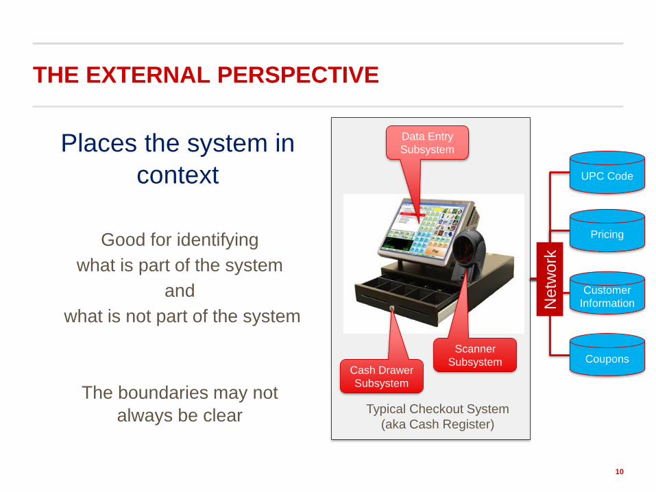
Places the system in
context
Good for identifying
what is part of the system
and
what is not part of the system
The boundaries may not
always be clear
THE EXTERNAL PERSPECTIVE
10
UPC Code
Pricing
Customer
Information
CouponsScanner
SubsystemCash Drawer
Subsystem
Data Entry
Subsystem
Typical Checkout System
(aka Cash Register)
Netw
ork

THE INTERACTION PERSPECTIVE
How the system interacts with its
environment, users, or components
1. Use Case Diagrams
How actors interact with a system
Especially useful for requirements
gathering and initial work with clients
2. Sequence Diagrams
How entities operate with one another
in specific order
Other diagram types are available
11

1. (start) Customer approaches the counter and tells the cashier what she wants
2. The cashier enters the beverage order into the point-of-sale system (POS)
3. The cashier asks for the customer’s name and notes it on the order
4. The customer pays for the order5. The cashier records the payment6. The cashier communicates the order
details to the barista 7. The barista prepares the beverage order8. Upon completion of the order, the barista
places the beverage on the pick-up counter and calls the customer’s name
9. The customer picks up the beverage and walks away (end).
LET’S START WITH A SIMPLE EXAMPLE:
ORDERING COFFEE AT A COFFEE SHOP
12

THE STORY IS RICH IN INFORMATION
1. (start) Customer approaches the counter and tells the cashier what she wants
2. The cashier enters the beverage order into the point-of-sale system (POS)
3. The cashier asks for the customer’s name and notes it on the order
4. The customer pays for the order
5. The cashier records the payment
6. The cashier communicates the order details to the barista
7. The barista prepares the beverage order
8. Upon completion of the order, the barista places the beverage on the pick-up counter and calls the
customer’s name
9. The customer picks up the beverage and walks away.(end)
13

1. (start) Customer approaches the counter and tells the cashier what she wants
2. The cashier enters the beverage order into the point-of-sale system (POS)
3. The cashier asks for the customer’s name and notes it on the order
4. The customer pays for the order
5. The cashier records the payment
6. The cashier communicates the order details to the barista
7. The barista prepares the beverage order
8. Upon completion of the order, the barista places the beverage on the pick-up counter and calls the
customer’s name
9. The customer picks up the beverage and walks away.(end)
THE STORY IS RICH IN INFORMATION
14
Actors and Objects

1. (start) Customer approaches the counter and tells the cashier what she wants
2. The cashier enters the beverage order into the point-of-sale system (POS)
3. The cashier asks for the customer’s name and notes it on the order
4. The customer pays for the order
5. The cashier records the payment
6. The cashier communicates the order details to the barista
7. The barista prepares the beverage order
8. Upon completion of the order, the barista places the beverage on the pick-up counter and calls the
customer’s name
9. The customer picks up the beverage and walks away.(end)
THE STORY IS RICH IN INFORMATION
15
Systems
Actors and Objects

1. (start) Customer approaches the counter and tells the cashier what she wants
2. The cashier enters the beverage order into the point-of-sale system (POS)
3. The cashier asks for the customer’s name and notes it on the order
4. The customer pays for the order
5. The cashier records the payment
6. The cashier communicates the order details to the barista
7. The barista prepares the beverage order
8. Upon completion of the order, the barista places the beverage on the pick-up counter and calls the
customer’s name
9. The customer picks up the beverage and walks away.(end)
THE STORY IS RICH IN INFORMATION
16
Actions
Actors and Objects Systems

1. (start) Customer approaches the counter and tells the cashier what she wants
2. The cashier enters the beverage order into the point-of-sale system (POS)
3. The cashier asks for the customer’s name and notes it on the order
4. The customer pays for the order
5. The cashier records the payment
6. The cashier communicates the order details to the barista
7. The barista prepares the beverage order
8. Upon completion of the order, the barista places the beverage on the pick-up counter and calls the
customer’s name
9. The customer picks up the beverage and walks away.(end)
THE STORY IS RICH IN INFORMATION
17
Events
Actors and Objects Systems Actions

NEED: REPRESENT SYSTEMS, ACTORS AND OBJECTS, ACTIONS,
AND EVENTS AND HOW THEY COME TOGETHER
18

USE CASE DIAGRAMS
How actors interact with a system
An actor is a prospective user
It can also be external systems
A scenario is a sequence of steps between an actor and the system
Lists the steps in each successful and unsuccessful scenario that make up the interaction
Usually written as prose
A use case is a set of scenarios with a common user goal
One can distinguish business use cases from system use casesBusiness process design versus system process design
Design hint: a use case shows what a system does, not how it does it keep descriptions short, clear, and precise separate main flow of events from alternate and exceptional flows
Especially useful for requirements gathering and initial work with clients
19

1. (start) Customer approaches the counter,
cashier hears what customer orders
2. The cashier enters the customer order into
the point-of-sale system (POS)
3. The cashier asks customer for a name and
notes name on the customer order
4. The cashier gets the customer’s money to
cover the order
5. The cashier records the payment
6. The cashier communicates the order’s
details to the barista
7. (end)
USE CASE0: ORDERING AT A COFFEE SHOP FROM THE
CASHIER’S PERSPECTIVE
21Guide: actor action objects-of-action

1. (start) Customer approaches the counter, cashier hears what customer orders
a. If the store is presently out of the materials needed for the order, cashier tells customer “we are out of X” andsuggests a near alternative
b. cashier hears what customer orders instead
2. The cashier enters the customer order into the point-of-sale system (POS)
3. The cashier asks customer for a name and notes name on the customer order
4. The cashier gets the customer’s money to cover the order
5. The cashier records the payment
6. The cashier communicates the order’s details to the barista
7. (end)
USE CASE0: NOW AN ALTERNATIVE
22Guide: actor action objects-of-action

1. (start) Customer start app on his phone and logs in.
2. Customer picks preferred store.
3. Customer enters coffee choice.
4. App asks if “he would like anything else.”
5. Customer selects “checkout.”
6. App asks for payment.
7. Customer enters credit card number.
8. App validates the order.
9. Once done, App sends the order to the POS machine at
preferred store and leaves a confirm message in the
customer’s email inbox.
10. The cashier communicates the order’s details to the
barista
11. (end)
USE CASE0: ORDER FROM THE WEB
23Guide: actor action objects-of-action

WRITING USE CASE DIAGRAMS IN UML
Use cases: oval with text inside
Actors: stick figure
Dependencies, generalizations, associations
• Actors are really roles played by people. One person may play
multiple roles. • However, actors may also be another system.
• Actors and use cases each have names.
take customer
order
actor
Association
between actor
and use case
a use case
cashier

WRITING USE CASE DIAGRAMS IN UML
login
customer
Pick store
Pay for
order
Pick up
order
Place order
backend
Validate
login
Validate
order
deliver order
to store
Use Case0: Ordering coffee from the app

ONE WAY TO REDUCE NOTATIONS
Use Case Generalization
Child use case inherits behavior and meaning from parent use case
Child may add or override parent behavior
Child may be substituted wherever parent occurs
Validate Client
Check
Password
Check
Thumbprint
Verify
Retinal Scan
Generalization
Symbol and association Child Use Case
Parent Use Case

EXTENDING USE CASES
Efficient way to model optional system behavior
The extending use case may add behavior to the base use case, but:
The base use case must declare certain extension points
The extending use case may add additional behavior only at those extension
points
The Extended use case is meaningful on its own as it is independent of the
extending use case.
Place Order
Extension points
set priority
Place Rush
Order<<extend>>
(set priority)
Use Case0: Adding “priority” to Ordering coffee from the app

AVOIDING REPETITIVE DESCRIPTIONS
Put common event flows into a use case of its own and then include it into the
behavior of the (base) use case.
The include relationship is used to:
simplify large use case by splitting it into several use cases
represent common parts of the behaviors of other use cases
Place
Order
Track
Order
Validate
User
<<include>>
<<include>>
Validate User
Place
Order
Track
Order
~~~

GUIDELINES FOR CHOOSING RELATIONSHIPS
1. Use <<include>> to avoid repetition when you are repeating yourself in two or
more separate use cases
2. Use generalization when you are describing a variation on normal behavior,
and you wish to describe it casually
3. Use <<extend>> when you are describing a variation on normal behavior and
you wish to use the more controlled form, declaring your extension points in the
base use case
(taken from Martin Fowler’s UML Distilled)

SEQUENCE DIAGRAMS
Shows the flow between elements of a
system (the messaging sequence)
Classes (instances of classes)
Components
Subsystems
Actors
Time is explicitly shown and flows from
top to bottom
Use Case0
t
30

CONTROL FLOWS
Conditional Flow Loops
Use Case0
t
31

ADDITIONAL (USEFUL) NOTATIONS
t
Activate Entity
32

ADDITIONAL (USEFUL) NOTATIONS
t
Activate Entity
Destroy Entity
Deactivate
Entity
33

ADDITIONAL (USEFUL) NOTATIONS
t
Some time goes by
Specific
amount of
time goes by
34

ADDITIONAL (USEFUL) NOTATIONS
t
noteworthy internal
messaging
35

SHIFTING GEARS: STATE
state
a condition or situation in the life on an object during which it satisfies some
condition, performs some activity, or waits for some event
typically described by a set of attribute values
examples:
a coffee pot: state depends on current amount of coffee, temperature, …
an order: state can be pending, in processing, fulfilled, cancelled, delivered, ...
Empty
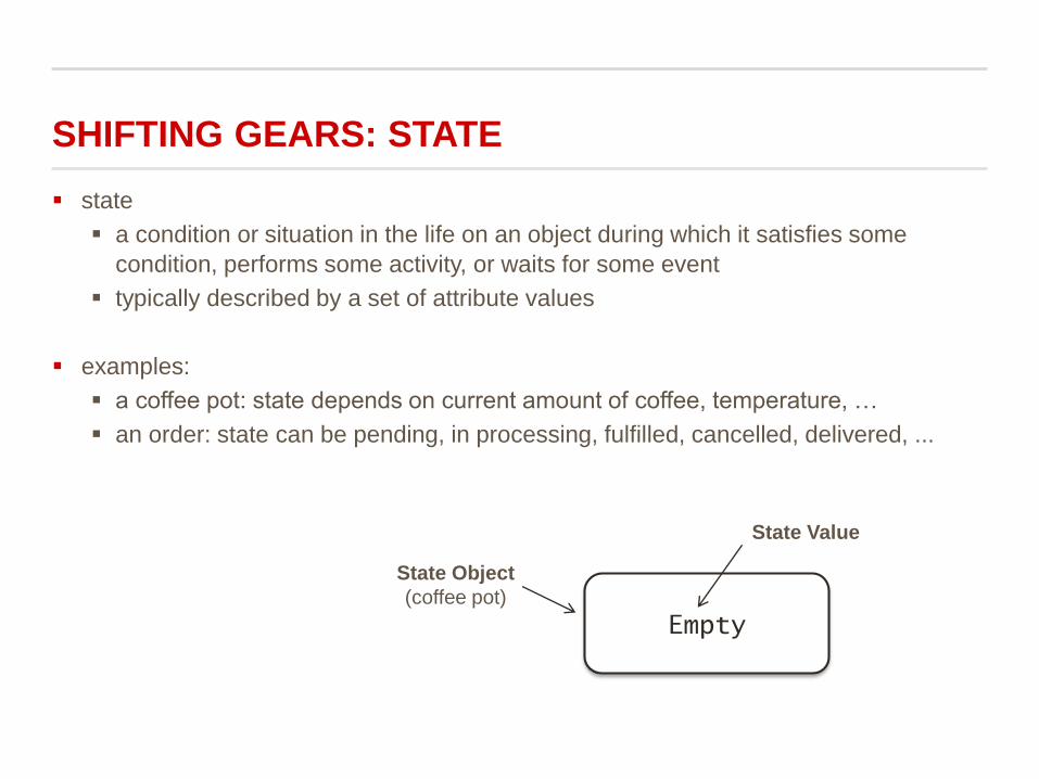
State Object
(coffee pot)
State Value

WHERE THERE ARE STATES,
THERE ARE TRANSITIONS
Events cause states to change
state transitions are considered to be atomic (cannot be interrupted)
state transitions may be labeled
Event [ Guard ] / Action
an event is a significant happening (a message or signal that is received)
an action is associated with a transition
a process that occurs quickly and is not interruptible
a guard is a logical condition
returns true or falseEmpty Filling
BrewStarts
Action/Event
State Transition
Statei
Statej

MORE ON STATES & STATE TRANSITIONS
Examples:
1. Credit card payment received
2. Payment received for order
3. Smart phone receives a call
Some events do not cause state change
self-transition
A state may have an activity associated with it
May take longer, and may be interrupted by event
Fowler’s notation: do /activity inside the state

STATE DIAGRAMS: CELL PHONE EXAMPLE
Idle
InCall
Hangup
CallArrives
Ringing
Answer/
startMedia

STATE DIAGRAMS: CELL PHONE EXAMPLE
Triggerless
Transition
initial state
Idle
InCall
Hanguptransition
CallArrives
Ringing
Answer/
startMedia
event
event
action

CONCURRENCY

STATE DIAGRAM GUIDELINES
Keep it simple
if diagrams get too big:
consider using composite states
or...multiple objects
trace through the states manually, compare against expected results
Confirm that all states are reachable under some combination of events
Confirm that no non-final state is a dead end

TO BE CONTINUED: MORE UML TO COME…
45
Class Diagrams
Moving from Diagrams to Code..