Embed Size (px)
Citation preview
Whilst Avon Protection has taken care to ensure the accuracy of the information contained herein it accepts no responsibility for the consequences of any
use thereof and also reserves the right to change the specification of goods without notice. Avon Protection accepts no liability beyond the set out in its
standard conditions of sale in respect of infringement of third party patents arising from the use of tubes or other devices in accordance with information
contained herein.
Avon Protection, Hampton Park West, Semington Road, Melksham, Wiltshire, SN12 6NB Telephone: +44 (0)1225 896705
Contact argus by e-mail: [email protected] or visit www.argusdirect.com
Avon Protection GR 13313-02 May 2016
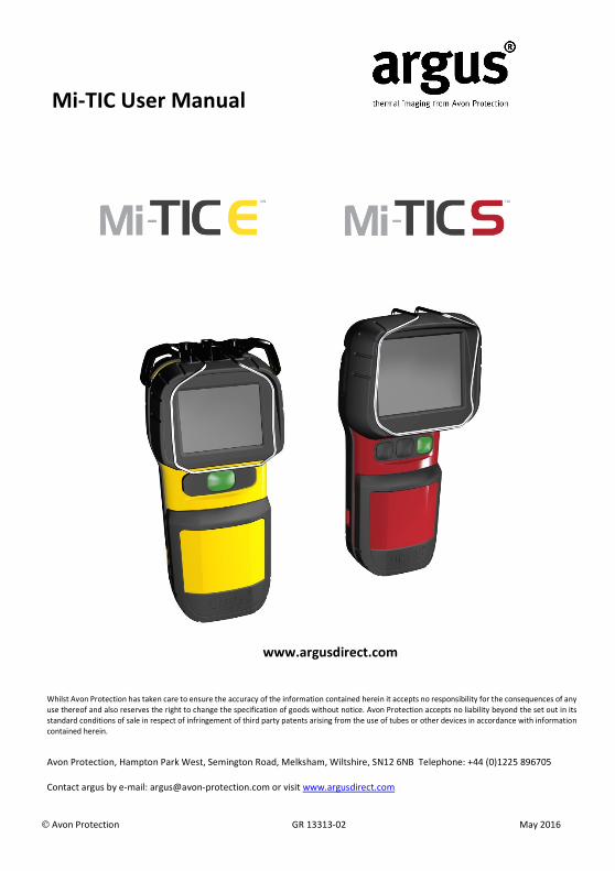
Mi-TIC User Manual
www.argusdirect.com

Avon Protection 2 GR13313-2 May 2016
CONTENTS
This manual contains information covering operation of the system and operating techniques,
user maintenance and care of the product.
1 SAFETY AND REGULATORY INFORMATION ................................................................... 4 1.1 FCC COMPLIANCE INFORMATION (US).......................................................................... 4 1.2 TUV Label ...................................................................................................................... 4 1.3 NFPA 1801 ..................................................................................................................... 4 1.4 ANSI 12.12.01 Class I Div2 Groups C & D Non-Incendive .............................................. 5 1.5 CAMERA WARNINGS/CAUTIONS ................................................................................... 5 2 INTRODUCTION ............................................................................................................. 6 3 OPERATION AND USE .................................................................................................... 7 3.1 System Configuration (Camera Rear) ............................................................................ 7 3.2 System Configuration (Camera Front) ........................................................................... 7 3.3 System Configuration (Charger Front)........................................................................... 8 3.4 System Configuration (Charger Rear) ............................................................................ 8 3.5 Display ........................................................................................................................... 9 3.6 Getting Started ............................................................................................................ 10 3.7 Camera Features ......................................................................................................... 11
3.7.1 Application Modes .............................................................................. 11 3.7.2 Direct Temperature Measurement .................................................... 18 3.7.3 Tri-Mode Sensitivity ............................................................................ 18 3.7.4 Zoom ................................................................................................... 19 3.7.5 Time and Date .................................................................................... 19 3.7.6 Image Capture .................................................................................... 19 3.7.7 Video Capture ..................................................................................... 20 3.7.8 Image Freeze ...................................................................................... 20 3.7.9 Image Playback ................................................................................... 20 3.7.10 Video Playback .................................................................................... 20 3.7.11 Laser Pointer ....................................................................................... 21 3.7.12 Electronic Compass ............................................................................. 22 3.7.13 Heat Seeker and Cold Seeker ............................................................. 23
3.8 Display Warning Graphics ........................................................................................... 24 3.8.1 Over-temperature Warning ................................................................ 24 3.8.2 General System Failure Warning ........................................................ 24
3.9 NFPA1801 ‘TI BASIC’ and ‘TI BASIC-PLUS’ operational formats ................................... 25 3.10 Operating Notes .......................................................................................................... 26 4 BATTERIES AND CHARGING ......................................................................................... 28 4.1 Indications on Charger ................................................................................................ 28 4.2 Battery Life Indicator ................................................................................................... 29 4.3 Argus® Mi-TIC Charger Station Fixed / Vehicle Installation.......................................... 29
4.3.1 Horizontal Mounting .......................................................................... 29 4.3.2 Vertical Mounting ............................................................................... 31 4.3.3 “Daisychaining” Electrical Installation ................................................ 31
5 CONNECTING THE CAMERA TO A PC ........................................................................... 33 5.1 Changing the Start-Up Image ...................................................................................... 33

Avon Protection 3 GR13313-2 May 2016
5.2 How to Copy the Memory Card Contents to a PC ....................................................... 34 5.3 Diagnostic File ............................................................................................................. 35 6 CONFIGURATION SOFTWARE ...................................................................................... 36 6.1 Running the Configuration Tool .................................................................................. 36 6.2 Setting the Temperature Units .................................................................................... 37 6.3 Setting the Time and Date Format .............................................................................. 38 6.4 Synchronizing the Time and Date with the PC ............................................................ 38 6.5 “Black Box” Video Recording ....................................................................................... 39 6.6 Electronic Compass ..................................................................................................... 39 6.7 Heat Seeker and Cold Seeker ...................................................................................... 40 6.8 Application Modes ...................................................................................................... 40 6.9 Camera Function Button Set-up .................................................................................. 41 6.10 Restart ......................................................................................................................... 42 7 CLEANING, MAINTENANCE AND REPLACEABLE PARTS ............................................... 43 7.1 Cleaning / Inspection after Use ................................................................................... 43 7.2 Maintenance ............................................................................................................... 43 7.3 Replaceable Parts ........................................................................................................ 44 7.4 Replacing the Germanium Window Assembly ............................................................ 45
7.4.1 Removal .............................................................................................. 45 7.4.2 Refitting .............................................................................................. 46
8 SPECIFICATIONS........................................................................................................... 47

Avon Protection 4 GR13313-2 May 2016
1 SAFETY AND REGULATORY INFORMATION
Before using this product, the customer shall read and understand all the instructions and warnings. Avon
Protection does not accept responsibility for damage or injury resulting from failure to follow the
instructions provided.
Refer to Product Safety datasheet PSD776352A for safety and warning notes
1.1 FCC COMPLIANCE INFORMATION (US)
When using the argus® Mi-TIC camera or charging the argus® Mi-TIC camera and battery in the
Charger (charge mode), these modes have been tested and found to comply with the limits for a
Class B digital device, pursuant to part 15 of the FCC Rules. These limits are designed to provide
reasonable protection against harmful interference in a residential environment. This equipment
generates, uses and can radiate radio frequency energy and, if not installed and used in accordance
with the instruction manual, may cause harmful interference to radio communications.
When downloading data from the argus® Mi-TIC camera / Charger (data download mode), this mode
has been tested and found to comply with the limits for a Class A digital device, pursuant to part 15
of the FCC Rules. These limits are designed to provide reasonable protection against harmful
interference in a commercial environment. This equipment generates, uses, and can radiate radio
frequency energy and, if not installed and used in accordance with the instruction manual, may cause
harmful interference to radio communications. Operation of this equipment in a residential area is
likely to cause harmful interference in which case the user will be required to correct the interference
at their own expense.
Any modification not approved by Avon Protection could void the user’s authority to operate this
equipment.
1.2 TUV Label
1.3 NFPA 1801
The following camera models
• MI-320-3-S • MI-320-1-E • MI-320-1-NFPA
• MI-329-3-S • MI-329-1-E • MI-329-1-NFPA
• MI-320-3-E • MI-320-3-NFPA
• MI-329-3-E • MI-329-3-NFPA
comply with the requirements of NFPA 1801 standard on Thermal Imagers for the Fire Service 2013
edition and bear the appropriate labelling.
To maintain NFPA 1801 / ANSI 12.12.01 compliance, cameras must be used with ARG_MI_BLPSN,
ARG_MI_BLPYN or ARG_MI_BLPXN batteries.
See the product label for EU and other
regulatory information

Avon Protection 5 GR13313-2 May 2016
1.4 ANSI 12.12.01 Class I Div2 Groups C & D Non-Incendive
All argus® Mi-TIC camera models, when marked, are suitable for use in Class 1, Division 2, Groups C, D or
Non-Hazardous Locations only.
These cameras are supplied with batteries of type ARG_MI_BLPSN, ARG_MI_BLPYN or ARG_MI_BLPXN
which are also marked for use in hazardous locations and must always be used with the camera in
hazardous locations.
Warning - explosion hazard - substitution of argus camera and/or argus battery pack components may
impair suitability for Class 1, Division 2.
1.5 CAMERA WARNINGS/CAUTIONS
• All users should familiarise themselves with the correct operation, functionality and features of
the camera before use.
• argus® Mi-TIC cameras are safe when handled and used according to the guidelines included
here, in the product safety data sheet PSD776352AA and within the environmental operating
environment specified in the data sheet (see section 9).
• The cameras are an aid to fire, search and rescue operations. They are not intended to provide
a safety function or as a replacement for established safety procedures.
• The argus® Mi-TIC camera can only be serviced by authorised personnel.
• Where the camera is used at an ambient temperature greater than +40 °C, suitable protective
gloves shall be worn to hold the camera; these should have a temperature rating at least 20 °C
above the ambient temperature.
• Avon Protection recommends that the argus® Mi-TIC camera is stored in the supplied package or
an alternative case supplied by Avon Protection.
• If users wish to mark or apply identification labels to their cameras they should ensure that their
marking does not create a hazard (e.g. flammable) or obscure certification information. Avoid
the use of solvents as these may degrade the camera housing. Users may prefer to use the
custom splash screen as an alternative, see section 5.1
• LASER Warning and Safety Measures
Observe all appropriate country-specific safety measures for the use of class 3R laser equipment.
Never aim the laser at a person’s eyes as this may cause permanent damage.
This Laser must only be used by properly trained personnel.

Avon Protection 6 GR13313-2 May 2016
2 INTRODUCTION
The argus® Mi-TIC E and Mi-TIC S are the latest generation of the argus® Thermal Imaging Camera (TIC) from
Avon Protection. With over 35 years experience in fire-fighters’ thermal imaging, argus continues to
produce high quality, affordable systems designed for fire and heat detection for use with civilian, industrial
and military rescue services.
The argus® Mi-TIC E and Mi-TIC S have been designed with digital imaging technology for a sharper picture
and uses the highly successful Amorphous Silicon (ASi) Microbolometer Detector that is in use by many of
the world’s fire brigades.
Every argus® Mi-TIC E and Mi-TIC S are supplied with a unique dual use desktop / in-truck charger station
which securely retains and charges both the thermal imager and a spare battery. The charger stations can
be daisy-chained together up to a maximum of six units.
The argus® Mi-TIC E and Mi-TIC S are a simple, small, lightweight but robust, self-contained camera system,
which has fully automatic operation; no control or adjustment is required in use. Through proper use, the
user will be able to:
• See through dense smoke and in darkness.
• Detect and display the relative temperatures of objects within the scene.
• Locate the seat and spread of the fire.
• Move swiftly in search and rescue of casualties.
• Have the ability to see in zero visibility conditions.
• Significantly improve safety and mobility.
• Monitor temperatures for preventive maintenance and condition monitoring of equipment.
The argus® Mi-TIC E and Mi-TIC S are designed to withstand the high temperatures, knocks and driving
spray often encountered in the fire-fighting environment and has many features that can be customised
by the end user. These features include:
• Direct Temperature Measurement up to 1100°C / 2000°F (Mi-TIC S, Mi-TIC); 760°C / 1400°F (Mi-TIC E)
• Up to 7 application specific colour modes (Fire, Overhaul, Size Up, Inspection, White Hot, Missing
Persons and Black Hot)
• Customisable Start-up Screen
• X2 and X4 Zoom
• Time and Date
• Configurable function buttons
• User Replaceable Germanium window.
• Image capture/playback and video capture with embedded storage of up to 1000 images and 8 hours
of video.
• Laser Pointer (Mi-TIC S only)
• Electronic Compass (Mi-TIC S only)
• Heat and Cold Seeker (Mi-TIC S only)
The following versions are subject to export controls.
An export licence will be required if exported outside the EU.
MI-320-n-xxxxx
The following versions are exempt from export controls.
MI-329-n-xxxxx
n = 1 (1 button) or 3 (3 button); xxxx = NFPA, E or S

Avon Protection 7 GR13313-2 May 2016
3 OPERATION AND USE
3.1 System Configuration (Camera Rear)
Mi-TIC E Mi-TIC S
1. 2.7” LCD Display 1. 3.5” LCD Display
2. Display Bumper 2. Display Bumper
3. Pocket Clip (removable) 3. Pocket Clip (removable)
4. Docking latch 4. Docking latch
5. Battery 5. Battery
6. Docking connector 6. Docking Connector
7. Function button 1 (Zoom, Video *) 7. Function button 1 (Zoom, Video *)
8. Function button 2 (Application Mode, Image*) 8. Function button 2 (Application Mode, Image*)
9. Green ON/OFF Button 9. Green ON/OFF Button
10. Lanyard Loops
*default settings
3.2 System Configuration (Camera Front)
1. Replaceable Germanium Window 1. Laser pointer
2. Window Release Latch 2. Lanyard Loops
3. Replaceable Germanium Window
4. Window Release Latch

Avon Protection 8 GR13313-2 May 2016
3.3 System Configuration (Charger Front)
1. Docking bay 2 (spare battery) 5. Camera latching mechanism
2. Docking bay 1 (camera with battery) 6. USB port (front)
3. Camera eject mechanism 7. Charging status LEDs
4. Camera release button 8. Front cover (removable)
Up to six chargers can be powered in a “daisy chain” configuration. Connections should
be made via the green power connectors located underneath the removable front cover.
The “daisy chain” power circuit contains a replaceable 10 A fuse. This is also located
underneath the removable front cover. See section 4.3 for installation details.
3.4 System Configuration (Charger Rear)
1. USB port (rear) 2. Power connector (single charger only)

Avon Protection 9 GR13313-2 May 2016
3.5 Display
16
15
14
11
10
9
8
7
17 18 19
1
2
12
13
6 5 4 3
1. Colour reference bar 11. Image Capture
2. Spot Temperature Target 12. Heat Seeker Marker*
3. Spot Temperature Reading 13. Cold Seeker Marker*
4. Battery Bar 14. Video Capture
5. Application mode 15. Zoom
6. Operational Format 16. Low Sensitivity Mode
7. Compass* 17. Time and Date
8. Cold Seeker Temperature Reading* 18. General System Failure Warning
9. Heat Seeker Temperature Reading* 19. Over Temperature Warning
10. Laser Pointer*
* Mi-TIC S only
Avon Protection 10 GR13313-2 May 2016
3.6 Getting Started
The packing case contains the following items (see Quick Start Guide):
• Camera with pocket clip fitted
• Charger Station
• Quick Start Guide
• Two rechargeable battery packs
• USB Lead
• Retractable lanyard
• Power Supply Kit:
• Mains power supply
• Set of interchangeable plugs
• Vehicle power lead (12 V)
• Universal Mounting Plate for Charger with 2 mounting screws
• 3 mm hex key (for attaching charger to Universal Mounting Plate)
• 2.5mm hex key (for attaching Picatinny rail – Mi-TIC only)
• 2 mm hex key (for attaching pocket clip and lanyard loop – MI-TIC and Mi-TIC E only)
Basic Operation
• Turn the camera on with a short press of the green button.
• After about one second a start-up image will appear on the screen. (This image may
be changed – see section 5.1). After a few more seconds the display will show the
thermal image.
• The time and date will be displayed for a further 5 seconds.
• Always check the battery indication to verify adequate power and check that a good
thermal image is displayed before commencing operational use.
• While the camera is in operation, it will recalibrate to maintain its performance and
image quality. During recalibration, an internal shutter closes and the image will
briefly freeze while the internal electronics optimises the performance of the sensor.
This occurs more frequently when first turned on, then the calibration interval
increases as the internal temperature of the camera stabilises.
• To turn the camera off, press and hold the green button for two seconds until the
camera turns off.
Avon Protection 11 GR13313-2 May 2016
3.7 Camera Features
3.7.1 Application Modes
The argus® Mi-TIC E and Mi-TIC S have up to seven application modes:
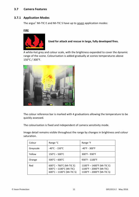
FIRE
Used for attack and rescue in large, fully developed fires.
A white-hot grey and colour scale, with the brightness expanded to cover the dynamic
range of the scene. Colourisation is added gradually at scenes temperatures above
150°C / 300°F.
The colour reference bar is marked with 4 graduations allowing the temperature to be
quickly assessed.
The colourisation is fixed and independent of camera sensitivity mode.
Image detail remains visible throughout the range by changes in brightness and colour
saturation.
Colour Range °C Range °F
Greyscale -40°C - 150°C -40°F - 300°F
Yellow 150°C – 500°C 300°F - 930°F
Orange 500°C – 600°C 930°F - 1100°F
Red 600°C – 760°C (Mi-TIC E)
600°C – 1100°C (Mi-TIC)
600°C – 1100°C (Mi-TIC S)
1100°F – 1400°F (Mi-TIC E)
1100°F – 2000°F (Mi-TIC)
1100°F – 2000°F (Mi-TIC S)

Avon Protection 12 GR13313-2 May 2016
OVERHAUL
Used for checking for hot spots after the fire is out.
A white-hot grey scale, expanded to cover the dynamic range of the scene. Red
colourisation is added to the hottest 2% scene, regardless of absolute temperature.
Yellow colourisation is added to the next hottest 5% of the scene regardless of
absolute temperature.
Where there is no significantly warmer area, no red or yellow shows.
The colour reference bar has no temperature scale.
Range °C Range °F
Red Hottest 2%
Yellow Next hottest 5%
Dynamic
range
-40°C - 760°C (Mi-TIC E)
600°C – 1100°C (Mi-TIC)
600°C – 1100°C (Mi-TIC S)
-40°F - 1400°F (Mi-TIC E)
1100°F – 2000°F (Mi-TIC)
1100°F – 2000°F (Mi-TIC S)
This function is part of the TI BASIC PLUS operational format (see 3.10)
Avon Protection 13 GR13313-2 May 2016
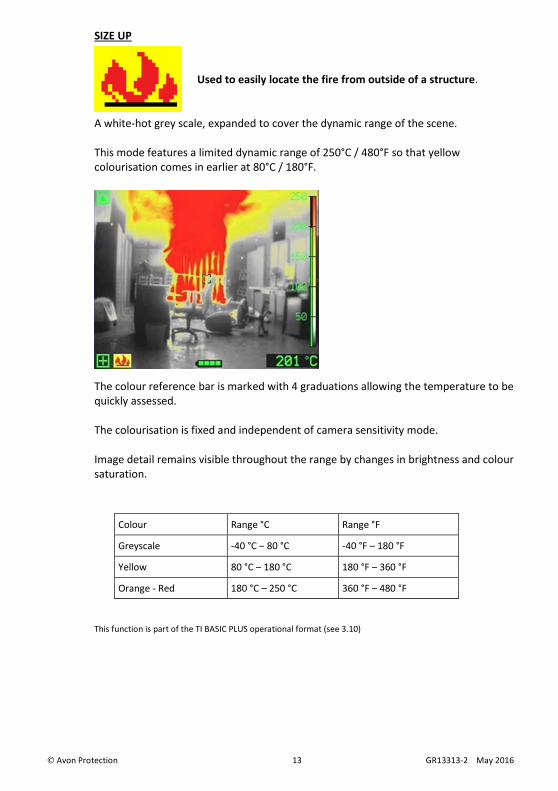
SIZE UP
Used to easily locate the fire from outside of a structure.
A white-hot grey scale, expanded to cover the dynamic range of the scene.
This mode features a limited dynamic range of 250°C / 480°F so that yellow
colourisation comes in earlier at 80°C / 180°F.
The colour reference bar is marked with 4 graduations allowing the temperature to be
quickly assessed.
The colourisation is fixed and independent of camera sensitivity mode.
Image detail remains visible throughout the range by changes in brightness and colour
saturation.
Colour Range °C Range °F
Greyscale -40 °C – 80 °C -40 °F – 180 °F
Yellow 80 °C – 180 °C 180 °F – 360 °F
Orange - Red 180 °C – 250 °C 360 °F – 480 °F
This function is part of the TI BASIC PLUS operational format (see 3.10)

Avon Protection 14 GR13313-2 May 2016
INSPECTION
Used for predictive maintenance to check equipment and
buildings to help prevent fire.
A white hot, full colour scale (black, blue, purple, orange, yellow through to white),
expanded to cover the dynamic range of the scene.
The colour reference bar has no temperature scale.
Image detail remains visible throughout the range by changes in brightness and colour
saturation.
Range °C Range °F
Dynamic range -40°C - 760°C (Mi-TIC E)
600°C – 1100°C (Mi-TIC)
600°C – 1100°C (Mi-TIC S)
-40°F - 1400°F (Mi-TIC E)
1100°F – 2000°F (Mi-TIC)
1100°F – 2000°F (Mi-TIC S)
This function is part of the TI BASIC PLUS operational format (see 3.10)

Avon Protection 15 GR13313-2 May 2016
WHITE HOT
Used for general search, with no colourisation.
A white-hot grey scale, expanded to cover the dynamic range of the scene.
The colour reference bar has no temperature scale.
Image detail remains visible throughout the range by changes in brightness.
Range °C Range °F
Dynamic
range
-40°C - 760°C (Mi-TIC E)
600°C – 1100°C (Mi-TIC)
600°C – 1100°C (Mi-TIC S)
-40°F - 1400°F (Mi-TIC E)
1100°F – 2000°F (Mi-TIC)
1100°F – 2000°F (Mi-TIC S)
This function is part of the TI BASIC PLUS operational format (see 3.10)
Avon Protection 16 GR13313-2 May 2016
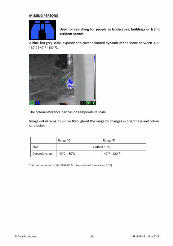
MISSING PERSONS
Used for searching for people in landscapes, buildings or traffic
accident scenes.
A blue-hot grey scale, expanded to cover a limited dynamic of the scene between -40°C
- 80°C (-40°F - 180°F).
The colour reference bar has no temperature scale.
Image detail remains visible throughout the range by changes in brightness and colour
saturation.
Range °C Range °F
Blue Hottest 10%
Dynamic range -40°C - 80°C -40°F - 180°F
This function is part of the TI BASIC PLUS operational format (see 3.10)

Avon Protection 17 GR13313-2 May 2016
BLACK HOT (only available on -C variant)
Used for general search
A black-hot grey scale, expanded to cover the dynamic range of the scene.
The colour reference bar has no temperature scale.
Image detail remains visible throughout the range by changes in brightness.
Range °C Range °F
Dynamic range -40°C - 760°C (Mi-TIC E)
600°C – 1100°C (Mi-TIC)
600°C – 1100°C (Mi-TIC S)
-40°F - 1400°F (Mi-TIC E)
1100°F – 2000°F (Mi-TIC)
1100°F – 2000°F (Mi-TIC S)
Note: The camera always starts up in FIRE mode. On 3-button cameras, to cycle through
the application modes, press the function button assigned to application mode. By
default, this is the centre function button.
This function is part of the TI BASIC PLUS operational format (see 3.10)

Avon Protection 18 GR13313-2 May 2016
3.7.2 Direct Temperature Measurement
The camera allows the operator to view the average
temperature of the centre spot of the scene (defined by the
target markings). The temperature reading is displayed in the
bottom right-hand corner of the display. This system is
intended to give the operator the ability to detect possible
hazards such as hot gas bottles or tanks, heat signatures of
people of objects, and to compare temperatures.
The temperature measurements feature can be changed between degrees Celsius or
degrees Fahrenheit by using the PC Configuration Tool software (see section 6.2).
In ‘Fire’ application mode, a green column against the temperature reference scale also
shows the spot temperature.
Notes:
• The camera can measure scene temperatures between -40°C and +1100°C (-40°F and
+2000°F).
• The object being measured must fully fill the target marks to get a good reading.
• If the temperature is higher than the maximum, the display will show “1100+C” in red.
• If the temperature is lower than the minimum, the display will show “----”
• Different types of materials have different infrared emission characteristics. This will
affect the accuracy of the temperature reading. Variations can also be caused by the
distance from the object. This temperature measurement must be regarded as an
indication and not a guaranteed reading.
3.7.3 Tri-Mode Sensitivity
The Argus® Mi-TIC has three levels of sensitivity: High, Low and Extended Low. These
levels provide the user with a thermal image over the widest possible temperature
range. The Argus® Mi-TIC will switch to the optimum level of sensitivity automatically
and will indicate when it is not in high sensitivity mode by displaying a green coloured
solid triangle symbol at the top left of the display.
• High Sensitivity Mode
The Argus® Mi-TIC will operate in High Sensitivity mode under normal operating
conditions. This mode produces a clear image with lots of detail and low levels of noise.
The temperature range for this mode is between −40 °C and 150 °C (−40 °F and 302 °F).
• Low Sensitivity Mode

Avon Protection 19 GR13313-2 May 2016
The Argus® Mi-TIC will automatically switch to Low Sensitivity mode
when higher temperatures have been detected, a small green triangle
symbol will be displayed in the top left corner to indicate this. The
image produced will still be clear with lots of detail, although some
additional noise will be visible in the cooler areas of the scene. The
temperature range for this mode is up to 400 °C (750 °F).
• Extended Low Sensitivity Mode
The Argus® Mi-TIC will automatically switch to Extended Low
Sensitivity mode when higher temperatures have been detected, a
small green triangle symbol will be displayed in the top left corner to
indicate this. The image produced will still be clear with lots of detail,
although even more noise will be visible in the cooler areas of the
scene. The temperature range for this mode is up to 1100°C / 2000°F (Mi-TIC S, Mi-TIC);
760°C / 1400°F (Mi-TIC-E).
3.7.4 Zoom
A short press on the left-hand function button
operates the zoom feature. The zoom symbol,
magnifying glass, will appear on the left-hand side of
the display.
The temperature measurement sample window is also
expanded to suit.
This function is part of the TI BASIC PLUS operational format (see 3.9)
3.7.5 Time and Date
On start-up, the time and date are displayed at the
top of the screen for 5 seconds.
The date format and time can be adjusted using
the software configuration tool (see section 6.3).
3.7.6 Image Capture
Up to 1,000 images can be captured. Images are stored in the camera
embedded storage. These images can then be viewed or deleted using
the camera or by downloading on to a PC (see section 5).
To capture an image, press the function button assigned to image
capture (see section 6.9 for function button set-up).

Avon Protection 20 GR13313-2 May 2016
The image capture symbol appears for a short time on the left-hand side of the LCD
display. The number of the images remaining will be indicated on the display.
Images are stored on the camera in compressed .jpg format.
This function is part of the TI BASIC PLUS operational format (see 3.9)
3.7.7 Video Capture
Videos are stored in the camera’s embedded storage in Motion
JPEG format in an .avi file. The files have a maximum length of 10
minutes to simplify transfer to a computer. The camera will
automatically start a new file every 10 minutes.
Video files can be copied to a computer using the USB lead. 10 minutes of video typically
generates a 100 MB file.
This function is part of the TI BASIC PLUS operational format (see 3.9)
3.7.8 Image Freeze
Image freeze allows the fire-fighter to pause the image on the screen to analyse in
more detail. This can be assigned to both short and long button functions.
On a short press the image is frozen until the button is pressed again, or a timeout of
15 seconds is reached.
On a long press the image is frozen until the button is released.
This function is part of the TI BASIC PLUS operational format (see 3.9)
3.7.9 Image Playback
Image playback allows fire-fighters to review images at the scene.
Once in image playback mode, the following button functions will apply
Left button press Previous image
Left button hold Skip backwards 5 images
Centre button press Next image
Centre button hold Skip forwards 5 images
Green button Return to normal
operation(TI BASIC mode)
This function is part of the TI BASIC PLUS operational format (see 3.9)
3.7.10 Video Playback
Video playback allows fire-fighters to review video at the scene.

Avon Protection 21 GR13313-2 May 2016
Once in video playback mode, videos will play automatically and the following button
functions will apply
Left button short press Restart current video
Left button double press
(within 3 seconds)
Previous video
Left button hold Skip backwards 5 videos
Centre button press Next video
Centre button hold Skip forwards 5 videos
Green button Return to normal
operation(TI BASIC mode)
This function is part of the TI BASIC PLUS operational format (see 3.9)
3.7.11 Laser Pointer
A built-in laser pointer to aid fire-fighters with communication when
identifying hot spots.*
This function is part of the TI BASIC PLUS operational format (see 3.9)
For safety reasons the laser has a 10 second timeout
*Mi-TIC S only

Avon Protection 22 GR13313-2 May 2016
3.7.12 Electronic Compass
An electronic compass provides improved situational awareness by
displaying N, NE, E, SE, S, SW, W or NW depending on which way the
camera is pointing.* *Mi-TIC S only
The compass will work within 45 degrees from vertical in both axes.
When the camera is tilted past 45degrees, the tilt symbol is displayed instead of
the heading.
The Cameras compass must be calibrated with each battery, to compensate for any
magnetic offsets.
When a compass requires calibration the calibrate symbol is displayed.
The camera must then be rotated through all axes, as shown below.
When the calibration has been successful, the heading will be displayed in yellow for
10 seconds, and then turn back to the standard green heading.
These settings will be saved for future use, therefore when the camera is restarted the
compass will be displayed immediately.
If during use the compass is rotated through all the axes and a completed calibration
is performed, the compass will save the new calibration and turn yellow for 10 seconds.
If during use, the compass appears inaccurate, this recalibration routine can be
performed to ensure accuracy.
Warning:
The accuracy of the magnetic compass will depend on correct calibration and isolation
from external magnetic interference. Interference can be caused by, but not limited
to, soft iron structures and electrical equipment. The compass should be used as an
aid only and not relied on as a primary means of navigation.
This function is part of the TI BASIC PLUS operational format (see 3.9)
Avon Protection 23 GR13313-2 May 2016
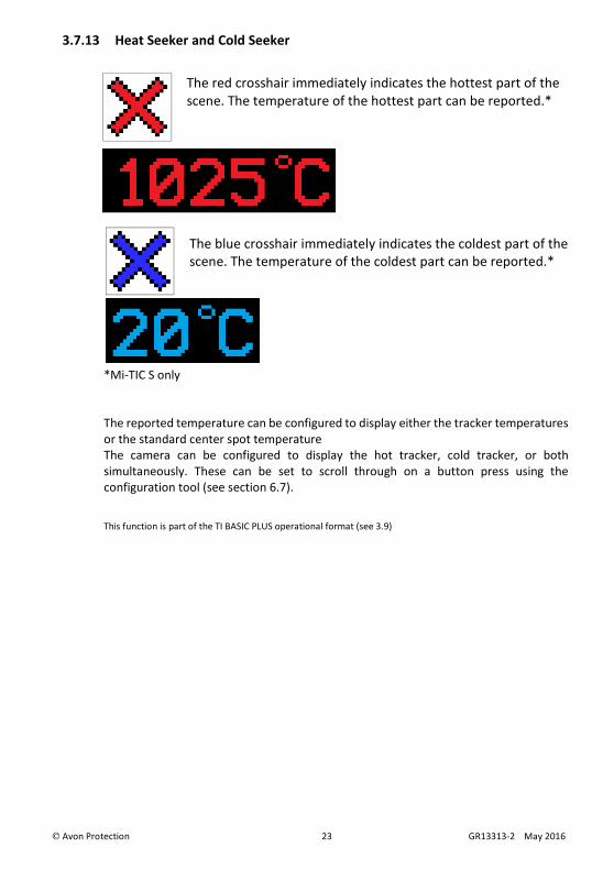
3.7.13 Heat Seeker and Cold Seeker
The red crosshair immediately indicates the hottest part of the
scene. The temperature of the hottest part can be reported.*
The blue crosshair immediately indicates the coldest part of the
scene. The temperature of the coldest part can be reported.*
*Mi-TIC S only
The reported temperature can be configured to display either the tracker temperatures
or the standard center spot temperature
The camera can be configured to display the hot tracker, cold tracker, or both
simultaneously. These can be set to scroll through on a button press using the
configuration tool (see section 6.7).
This function is part of the TI BASIC PLUS operational format (see 3.9)

Avon Protection 24 GR13313-2 May 2016
3.8 Display Warning Graphics
The Argus® Mi-TIC is equipped with an advanced microprocessor based control and user
warning system. In addition to controlling the automatic operation of the camera to
ensure the best possible picture at all times, the control system provides graphics on
the display to alert the user to certain conditions as follows:
3.8.1 Over-temperature Warning
The internal temperature of the camera is above the correct
operating range. The camera must be turned off to cool down and
prevent permanent damage.
If the user ignores this warning and continues to operate the
camera in very high temperatures, the warning symbol will flash.
When the flashing temperature warning is present, the camera is very close to its
absolute operating limit and the image will start to degrade considerably. The user
must remove the unit from the high ambient temperature at this time; failure to
comply may result in permanent damage to the unit. Failure to act upon this level of
warning may result in serious damage to the system and may invalidate the warranty.
3.8.2 General System Failure Warning
The control system has detected an internal camera fault. Turn the
camera off for five minutes and turn back on again. If the warning
symbol is still present, or the symptoms return, contact your Avon
Protection representative.
Failure to act upon this level of warning may result in serious damage to the system
and may invalidate the warranty.

Avon Protection 25 GR13313-2 May 2016
3.9 NFPA1801 ‘TI BASIC’ and ‘TI BASIC-PLUS’ operational formats
When switched on the Argus® Mi-TIC camera complies with the
requirements of NFPA BASIC operational format providing
temperature related colour imaging.
A short press of the green button will also always revert the
camera to this condition.
Certain features are beyond the scope of NFPA basic mode, and when activated the
symbol shown here will show in the bottom left of the screen. These are activated by
pressing one of the black function buttons on a 3-button camera
The following Argus® Mi-TIC features are ‘PLUS’ features
• The ‘OVERHAUL’ Application Mode as detailed in section 3.7.1
• The ‘SIZE UP’ Application Mode as detailed in section 3.7.1
• The ‘INSPECTION’ Application Mode as detailed in section 3.7.1
• The ‘WHITE HOT’ Application Mode as detailed in section 3.7.1
• The ‘MISSING PERSONS’ Application Mode as detailed in section 3.7.1
• The ‘BLACK HOT’ Application Mode as detailed in section 3.7.1
• Zoom as detailed in section 3.7.4
• Image Capture as detailed in section 3.7.6
• Video Capture as detailed in section 3.7.7
• Laser Pointer as detailed in section 3.7.8
• Electronic Compass as detailed in section 3.7.9
• Heat Seeker and Cold Seeker as detailed in 3.7.10
Button functions can be changed or removed using the Argus® Mi-TIC Configuration
Tool detailed in section 6.

Avon Protection 26 GR13313-2 May 2016
3.10 Operating Notes
• Interpreting The Image – Relative Temperatures
The image displayed is simply a black and white picture of the infrared energy
entering the lens. The camera displays relative temperature differences between
individual objects and their surroundings irrespective of overall ambient
temperature.
The camera is set up to display objects at various shades between black for cooler
items and white for hotter bodies, e.g. in a room at 20 °C a cold drink would appear
black whilst a hot radiator would appear white. However, in a room at 250 °C, it is
possible that the same hot radiator may appear darker than, for example, burning
materials. Depending upon the application mode selected, the image may be
coloured according to actual temperature (Fire or Size Up mode) or relative
temperature (Overhaul, Inspection, WH, Missing Persons or BH mode).
• Identification of Fire and Hotspots
The camera will represent zones of very high temperature as white or red within
the picture. When sufficient heat has been detected, e.g. a large area of fire, the
camera will automatically enter low sensitivity mode. This will extend the dynamic
range of the camera and allow the image of surrounding objects to remain clearly
visible.
• Hidden Fires
It is possible that fires may be burning or smouldering behind doors, in ducting or in
wall or floor cavities. In such circumstances, the operator should look for areas that
appear whiter when compared with the surroundings. Overhaul mode is particularly
useful in this situation, as it would colour the hottest areas red.
For example, a fire behind a door will cause the door to appear whiter against the
background. Similarly, a white area on an otherwise dark wall could indicate an area
of fire behind the masonry.
• Search for Persons and Objects
The camera is not restricted to locating fires. In many cases, the fire-fighter will be
using the camera to search for casualties, to seek out dangerous items such as fuel
tanks or gas cylinders and also as an aid to navigation through unknown premises.
• Image Clarity
The sharpness and clarity of the image provided is related to the temperature of the
scene and objects in view. A cold room provides little infrared energy and less detail
is detected than in a warm environment where objects give off significant energy.
In general, the warmer the scene, the more thermal contrast and hence the greater
detail in the picture.

Avon Protection 27 GR13313-2 May 2016
• Heat Layers in Closed Spaces
In a major fire, a layer of hot gases may build up in the upper region of the closed
space. Attempting to use the camera in this hot layer will cause the image to
become featureless. By bringing the camera down beneath this layer, the unit is
able to provide the fire-fighter with a clearer picture of the scene ahead.
• Windows and Polished Surfaces
Glass is not transparent to long wavelength infrared energy and it is not possible for
the operator to use the camera to look through a window. A white window would
indicate that the window itself is relatively warm and may be being heated by a fire
behind it. Just as we see reflections in glass under normal circumstances, it is
possible that the camera can detect infrared reflections in glass, mirrors and
polished or painted surfaces. Care must be taken to ensure that the image seen is
not simply a reflection. Experience will give the operator added confidence.
• Control of Water Streams/Jets
When viewed through the camera, water streams from hose reels will appear black
against the background scene. The control and direction of a water flow can be
monitored by viewing its flow and effect on the fire through the camera. It may be
necessary, if employing a water wall, to drop the wall momentarily to view the
effects of the extinguishing stream.
• Smoke Types
The camera will provide vision through all types of smoke and steam.
• Lens Cleaning During Operation
The camera lens, like the BA visor, may become obscured during use. The lens may
be cleaned with a glove or cloth if necessary.

Avon Protection 28 GR13313-2 May 2016
4 BATTERIES AND CHARGING
The Argus® Mi-TIC camera is supplied with two Argus® Mi-TIC Lithium Iron Phosphate
Rechargeable Battery Packs (ARG_MI_BLPYN or ARG_MI_BLPSN). These battery type power
the camera for over 2 hours from a full charge regardless of operating mode (e.g. video
recording) and camera type. Batteries must be fully charged before first use.
The optional high capacity battery (ARG_MI_BLPL) gives over 5 hours use from a single charge.
Typical battery run times from a full charge are as follows:
Battery Type
Camera
Type
ARG_MI_BLPYN
ARG_MI_BLPSN
ARG_MI_BLPXN
ARG_MI_BLPL Optional non NFPA approved
ARG_MI_BAA Optional non NFPA approved
MI-32X-X-S 2h10 5h10 4h20
MI-32X-X-E
MI-32X-X-NFPA 2h30 6h00 5h00
Run times of a partially charged battery will be proportionally less. Always ensure adequate
power before commencing operational use.
Use at very low temperatures will also reduce battery run time.
4.1 Indications on Charger
No power applied or no battery fitted
Charging
Battery fully charged.
Battery too warm/cold for charging or other fault

Avon Protection 29 GR13313-2 May 2016
4.2 Battery Life Indicator
With a new, fully charged battery, the battery indicator will
show full with a solid green bar.
The battery indicator represents the normal run time of the
battery, 2 hours for the standard battery and 5 hours for the
optional large battery (ARG_MI_BLPL).
When the battery symbol turns orange, there is
approximately half of the battery life remaining.
When the battery symbol turns red, there is approximately a
quarter of battery life remaining.
When the battery symbol starts to flash, the time remaining
will typically be 10 - 15 minutes.
4.3 Argus® Mi-TIC Charger Station Fixed / Vehicle Installation
The Argus® Mi-TIC Charger Station can be mounted on any surface either horizontal or
vertically using the universal mounting plate and mounting screws supplied. Note: fixings
for attaching the mounting plate to the surface are NOT supplied.
Up to six (6) charger stations can be powered in a “daisy chain” configuration.
4.3.1 Horizontal Mounting
• Charger Station
• Universal Mounting Plate
• 3 mm hex key
• M4 x 30 mounting screws (2)
• AWG 18 gauge wire (Red and black) (not supplied)
• Small flat bladed screwdriver (not supplied)
• Large flat bladed screwdriver (not supplied)
Avon Protection 30 GR13313-2 May 2016
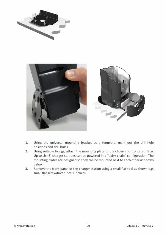
1. Using the universal mounting bracket as a template, mark out the drill-hole
positions and drill holes.
2. Using suitable fixings, attach the mounting plate to the chosen horizontal surface.
Up to six (6) charger stations can be powered in a “daisy chain” configuration. The
mounting plates are designed so they can be mounted next to each other as shown
below.
3. Remove the front panel of the charger station using a small flat tool as shown e.g.
small flat screwdriver (not supplied).

Avon Protection 31 GR13313-2 May 2016
4. Hook the charger station on to the universal mounting plate.
5. Fasten the charger station to the universal mounting plate with the M4 x 30
mounting screws using the 3 mm hex key as shown.
6. Replace the front panel on the charger station.
4.3.2 Vertical Mounting
Follow the same procedure as for a horizontal mounting, but on a vertical surface.
4.3.3 “Daisychaining” Electrical Installation
Connections should be made via the green power connectors located underneath the
removable front cover. The “daisy chain” power circuit contains a replaceable 10A fuse. This is
also located underneath the removable front cover.
1. Remove the front panels of the charger stations to be connected.

Avon Protection 32 GR13313-2 May 2016
2. Using 18 AWG wire or thicker, connect the terminals as shown overleaf, ensuring that the
positive (+ve) terminals are connected together and that the negative (-ve) terminals are
connected together.
3. Replace the front panels on the charger stations.
Note: Do not use the rear power connector when in the ‘daisy-chain’ configuration. All power
must be supplied through the front hard wiring connectors.

Avon Protection 33 GR13313-2 May 2016
5 CONNECTING THE CAMERA TO A PC
The camera has embedded storage which is used for:
• Changing the start-up image
• Storing images
• Storing videos
• Storing camera diagnostic information
• Updating the camera software
• Storing a copy of the Configuration Tool Software (see section 6)
• Storing a copy of the manual
5.1 Changing the Start-Up Image
A custom start-up image can be loaded into the camera as follows.
1. Generate an image file on a computer in the following format:
Name: Splash.bmp
File format: Bitmap
Dimensions (HxV): 320 x 240 pixels
Bit depth 24 Bit
File size: 230,454 bytes
It is recommended to use MS Paint to create the image file.
2. Turn the camera on.
3. Connect the camera to the computer via the Argus® Mi-TIC Charger Station and the
supplied USB lead.
4. The computer should recognise the memory card as a ‘Mass Storage Device’ and
open a file explorer window.
5. Copy the image file from the computer to the top level ‘ARGUS TIC’ directory.
6. Close the window.
7. On computers running MS Windows® it is recommended to select ‘Safely Remove
Hardware’ before disconnecting the camera.
8. Remove the camera from the Argus® Mi-TIC Charger Station.
9. Turn the camera off and back on. The camera will read the new image file when it
turns on.
10. Wait until the displayed status message clears.
11. Turn the camera off and back on again, the new splash screen image will appear at
start-up.
Keep a copy of the image file on your computer. The camera will rename the image file
on the memory card to XSPLASH.BMP after it has been successfully loaded into the
camera.
Avon Protection 34 GR13313-2 May 2016
In the event that the splash screen fails to load into the camera, the camera will rename
the image to ERRSPLASH.BMP. Providing the settings described above are adhered to, the
custom start-up image can be loaded into the camera.
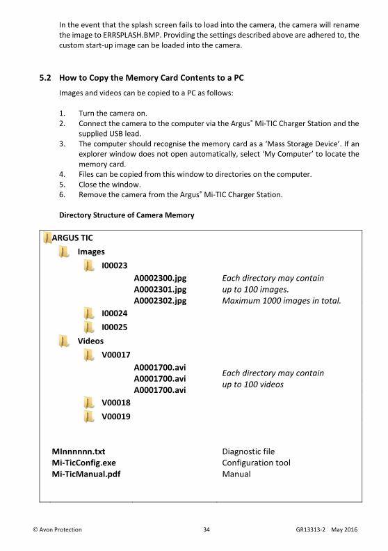
5.2 How to Copy the Memory Card Contents to a PC
Images and videos can be copied to a PC as follows:
1. Turn the camera on.
2. Connect the camera to the computer via the Argus® Mi-TIC Charger Station and the
supplied USB lead.
3. The computer should recognise the memory card as a ‘Mass Storage Device’. If an
explorer window does not open automatically, select ‘My Computer’ to locate the
memory card.
4. Files can be copied from this window to directories on the computer.
5. Close the window.
6. Remove the camera from the Argus® Mi-TIC Charger Station.
Directory Structure of Camera Memory
ARGUS TIC
Images
I00023
A0002300.jpg Each directory may contain
up to 100 images.
Maximum 1000 images in total.
A0002301.jpg
A0002302.jpg
I00024
I00025
Videos
V00017
A0001700.avi Each directory may contain
up to 100 videos A0001700.avi
A0001700.avi
V00018
V00019
MInnnnnn.txt
Mi-TicConfig.exe
Mi-TicManual.pdf
Diagnostic file
Configuration tool
Manual

Avon Protection 35 GR13313-2 May 2016
5.3 Diagnostic File
The diagnostic file can be found in the top level ‘ARGUS TIC’ directory on the memory
card. The name of the file is:
MInnnnnn.txt
(nnnnnn is the camera serial number)
The diagnostic file contains information about the camera which may be useful to Avon
Protection in diagnosing any camera faults. Avon Protection may ask you to copy this file
from the memory card to a computer and send it by email to Avon Protection for fault
finding.

Avon Protection 36 GR13313-2 May 2016
6 CONFIGURATION SOFTWARE
The Argus® Mi-TIC Configuration Tool is supplied on the camera’s embedded storage.
The Configuration Tool runs on a PC with Windows XP / Vista / Win7 / Win 8. This allows the
user to perform the following tasks:
• Set the temperature units to either °C or °F.
• Set the time and date format and synchronise the time and date with the PC
• Enable “black box” video recording
• Enable electronic compass
• Enable Heat Seeker and Cold Seeker
• Customise the operation of the camera’s function buttons to control:
• Zoom
• Fire, Overhaul, Size Up, Inspection, White Hot, Missing Persons or Black Hot
(-C variant only) Application Modes
• Image Freeze
• Image Capture
• Video Record
• Image Playback
• Video Playback
• Laser Pointer*
6.1 Running the Configuration Tool
To run the software, connect the argus® Mi-TIC to your computer using the argus® Mi-TIC
Charger Station and the supplied USB cable. The camera is recognised as a removable
disk. Navigate to the removable disk and open it.
Note: If the camera is not recognised as a removable disk, check that the camera is
connected to the PC and correctly docked in the charger station and switch the camera
off and back on again.
Run ‘Mi-TicConfig.exe’. The camera type is automatically recognised.

Avon Protection 37 GR13313-2 May 2016
6.2 Setting the Temperature Units
Select either C or F, then click the ‘Save Changes’ button circled in red below. Eject the
camera from the charger dock. Do not switch the camera off and back on again. The new
settings will be enabled.

Avon Protection 38 GR13313-2 May 2016
6.3 Setting the Time and Date Format
Select either GB or US, then click the ‘Save Changes’ button. Eject the camera from the
charger dock. Do not switch the camera off and back on again. The new settings will be
enabled.
6.4 Synchronizing the Time and Date with the PC
Check the “Synchronize time and date” box, then click the ‘Save Changes’ button. Eject
the camera from the charger dock. Do not switch the camera off and back on again. The
new settings will be enabled.

Avon Protection 39 GR13313-2 May 2016
6.5 “Black Box” Video Recording
Check the “Black Box Video Recording” box, then click the ‘Save Changes’ button. Eject
the camera from the charger dock. Do not switch the camera off and back on again. The
new settings will be enabled.
Note: When “Black box” video recording is enabled, image capture, video record and
image playback functions are disabled.
6.6 Electronic Compass
Check the “Black Box Video Recording” box, then click the ‘Save Changes’ button. Eject
the camera from the charger dock. Do not switch the camera off and back on again. The
new settings will be enabled.
Warning: When the compass is ENABLED, the camera will start up in TI BASIC PLUS
MODE

Avon Protection 40 GR13313-2 May 2016
6.7 Heat Seeker and Cold Seeker
Check the “Heat Seeker” box, “Cold Seeker” box or “Heat and Cold Seeker” box to enable
trackers. Check the Tracker Temperature box or Spot temperature box, then click the
‘Save Changes’ button. Eject the camera from the charger dock. Do not switch the camera
off and back on again. The new settings will be enabled.
6.8 Application Modes
Check the application modes to be enabled, then click the ‘Save Changes’ button. Eject
the camera from the charger dock. Do not switch the camera off and back on again. The
new settings will be enabled.

Avon Protection 41 GR13313-2 May 2016
6.9 Camera Function Button Set-up
The following camera functions can be assigned to either of the two function buttons.
Functions can be activated by either a short press (less than one second), or a long press
(three seconds).
• Zoom
• Cycle through selected Application Modes (Fire, Overhaul, Size Up, Inspection,
White Hot, Missing Persons or Black Hot (-C variant only)
• Image Freeze
• Image Capture
• Video Record
• Image Playback
• Video Playback
• Laser Pointer*
• Heat Seeker / Cold Seeker*
*Mi-TIC S only
To assign functions to buttons, select the desired combinations and then click the ‘Save
Changes’ button. Eject the camera from the charger dock. Do not switch the camera off
and back on again. The new settings will be enabled.

Avon Protection 42 GR13313-2 May 2016
6.10 Restart
If the Configuration Tool cannot identify the camera, remove the camera from the
docking station and restart the camera. This will update the camera identification.

Avon Protection 43 GR13313-2 May 2016
7 CLEANING, MAINTENANCE AND REPLACEABLE PARTS
7.1 Cleaning / Inspection after Use
After use and prior to stowing, the camera should be cleaned. This is best carried out using
a cloth soaked with warm soapy water.
Check the camera for any signs of damage that may have occurred during the preceding
use, for example front / rear window damage or case cracking due to extreme impacts or
case damage due to extreme heat.
Do not use coarse abrasives on the window surfaces, and ensure that any grit is removed
before rubbing to dry.
In cases of contamination or infection risk, seek expert advice in accordance with the
hazard encountered (e.g. foul water, Hazchem)
Solvents should not be used. If in doubt, contact your supplier.
7.2 Maintenance
No routine maintenance is required for the camera. If it is not in regular use, it should be
switched on for a period of ten minutes every month to check correct operation.
Batteries should be recharged every 6 months if not used.
Battery capacity can be expected to reduce over time. The Argus® Mi-TIC rechargeable
batteries use LiFePO4 cells which age to approximately 70% of original capacity after 2000
cycles under test conditions. Users should therefore expect to replace the batteries during
the camera lifecycle.
There are very few other ‘lifed’ components in the argus® Mi-TIC camera and repair /
replacement of these will be offered via Avon Protection or an authorised repair centre
subject to component availability.

Avon Protection 44 GR13313-2 May 2016
7.3 Replaceable Parts
The following items may be substituted by the user:
Item Description
USB Lead USB cable with Type B connector (2 metres)
Vehicle Charger
Lead Fuse
250 V 2 A Fast Acting Fuse, UL Certified. 1.25 x 0.25
inch (32 x 6 mm).
Do not use any other fuse type or rating.
The following items are available as spares and accessories from Avon Protection:
Part No. Description
ARG_MI_BHC Mi-TIC Black Hard Carry Case
ARG_MI_BLPSN Mi-TIC Rechargeable Battery
ARG_MI_BLPXN Mi-TIC Rechargeable Battery Xtra
ARG_MI_BLPYN Mi-TIC Rechargeable Battery Yellow
ARG_MI_BLPL Mi-TIC Rechargeable Battery Large
ARG_MI_BAA Mi-TIC AA battery
ARG_MI_CS Mi-TIC Charger Station
ARG_MI_DB Mi-TIC 2.7” Display Bumper
ARG_MI_DB_S Mi-TIC 3.5” Display Bumper
ARG_MI_LL Mi-TIC Double Lanyard Loop
ARG_MI_MB Mi-TIC Charging Shoe Mounting Bracket
ARG_MI_PSU Mi-TIC Power Supply
ARG_MI_RAIL Mi-TIC Picatinny Rail
ARG_MI_RL Mi-TIC Retractable Lanyard
ARG_MI_RWS Mi-TIC Replacement Ge Window (Short)
ARG_MI_SS Mi-TIC 2.7” Sunshroud
ARG_MI_PCLIP Mi-TIC Pocket Clip
ARG_MI_PCLIP_S Mi-TIC S Pocket Clip
ARG_MI_USB Mi-TIC USB Lead
ARG_MI_YHC Mi-TIC Yellow Hard Case
P7030NS Argus Neck Strap
P7030SC Argus Soft Carry Case
THERE ARE NO OTHER USER SERVICEABLE PARTS. If any damage beyond these parts
occurs, return the camera to Avon Protection or an authorised repair centre. Any attempt
at repair by unauthorised personnel may cause serious damage and will invalidate the
warranty.
Avon Protection 45 GR13313-2 May 2016
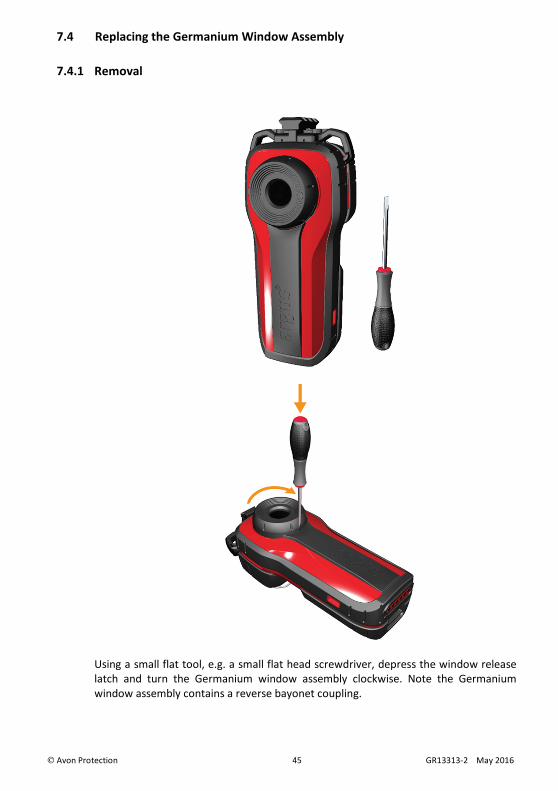
7.4 Replacing the Germanium Window Assembly
7.4.1 Removal
Using a small flat tool, e.g. a small flat head screwdriver, depress the window release
latch and turn the Germanium window assembly clockwise. Note the Germanium
window assembly contains a reverse bayonet coupling.

Avon Protection 46 GR13313-2 May 2016
7.4.2 Refitting
Locate the window assembly on the front of the camera and turn the window
assembly anti-clockwise until a click is heard.

Avon Protection 47 GR13313-2 May 2016
8 SPECIFICATIONS

Avon Protection 48 GR13313-2 May 2016

Avon Protection 49 GR13313-2 May 2016
EMEA
CUSTOMER SERVICE
Avon Protection
Hampton Park West
Melksham
Wiltshire, SN12 6NB
UK
T: +44 (0) 1225 896705
F: +44 (0) 1225 896301
E-mail: emeacustomerservice@ avon-protection.com
ASIA PACIFIC
CUSTOMER SERVICE
Avon Protection
Hampton Park West
Melksham
Wiltshire, SN12 6NB
UK
T: +44 (0) 1225 896705
F: +44 (0) 1225 896301
E-mail: emeacustomerservice@ avon-protection.com
AMERICAS
CUSTOMER SERVICE
Avon Protection Systems
1361 Brass Mill Road Suite F
Belcamp
Maryland 21017
USA
T: +1 (888) 286 6440
F: +1 (410) 273 1301
Email: [email protected]