Embed Size (px)
Citation preview
Series MHK2 ø12, ø16, ø20, ø25
Wedge Cam Operation Slide GuideAir Gripper (2 Finger)
2 types of finger materials 3 types of dust cover materialsLoad Resistant, Dust Cover for Adverse Environments
Standard: Carbon steelOptional: Stainless steel
Standard: Chloroprene rubber (CR) ···BlackOptional: Silicon rubber (Si) ···White
Fluoro rubber (FKM) ···Black
5-141
5-142
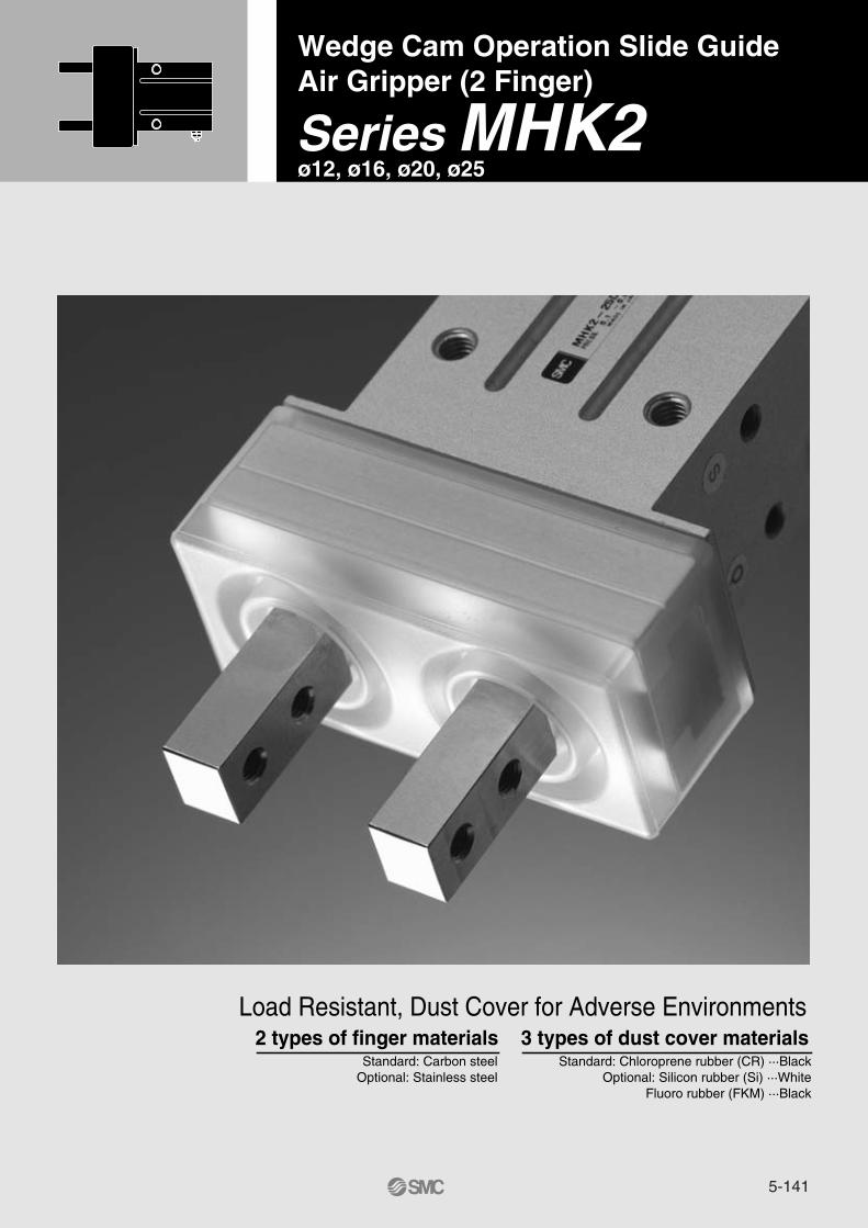
Wedge Cam Operation ProvidesDust Cover for Adverse
Built-in adjustment needlefor finger speedPossible to adjust the speed forfinger closing direction.
2 types of finger materialsare available for differentapplications.Standard: Carbon steelOptional: Stainless steel
Wedge cam structureThe wedge structure allows no lateralvibration along stroke direction oncework is held.
High rigiditySlide type guide bearing enableshighly rigid finger motion.
Improved performanceIncorporation of dust cover preventsdust, water, etc. from entering thebody and avoids generating dustand releasing grease from air gripper.
3 types of dust covers areavailable for use in differentenvironments.Standard: Chloroprene rubber (CR) ······BlackOptional: Silicon rubber (Si) ···White Fluoro rubber (FKM) ···Black
Wedge Cam Operation Slide Guide
Air Gripper (2 Finger)
Auto switch mountableGrooves for auto switch are located
Pin hole for positioningon top side
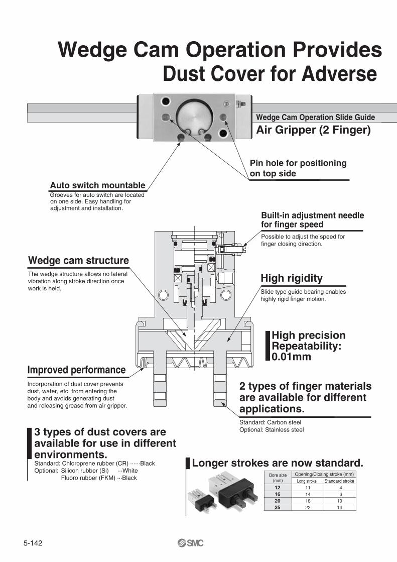
Longer strokes are now standard.Bore size
(mm)Opening/Closing stroke (mm)
Long stroke12162025
11141822
Standard stroke46
1014
High precision Repeatability:0.01mm
on one side. Easy handling foradjustment and installation.

5-143
Series
Standard typeseries MHK2
Long stroke typeseries MHKL2
Par
alle
l ope
ning
/clo
sing
VariationsModel Bore size
(mm)
12
16
20
25
12
16
20
25
Opening/Closingstroke (mm)
4
6
10
14
11
14
18
22
Options
Applications
Assembling
Loading/unloading workinto machine tools
Transferring
Universal Mounting
(Body tapped) (Body tapped)
(Body tapped) (Body through-hole)
Interchangeable with Series MHQG2
Series MHK2
High Precision and Rigidity.Environmental Conditions.
Axial mounting Vertical mounting
Lateral mounting
MHK2-12�MHK2-16�MHK2-20�MHK2-25�MHKL2-12�MHKL2-16�MHKL2-20�MHKL2-25�
Finger optionCarbon steel (Standard),Stainless steelDust cover optionChloroprene rubber (Standard)Fluoro rubberSilicone rubberAuto SwitchSolid state switchD-M9N(V), D-M9P(V), D-M9B(V)Water resistant (2 colour indication)D-M9�A(V)
5-144
—S
12162025
12 mm16 mm20 mm25 mm
2
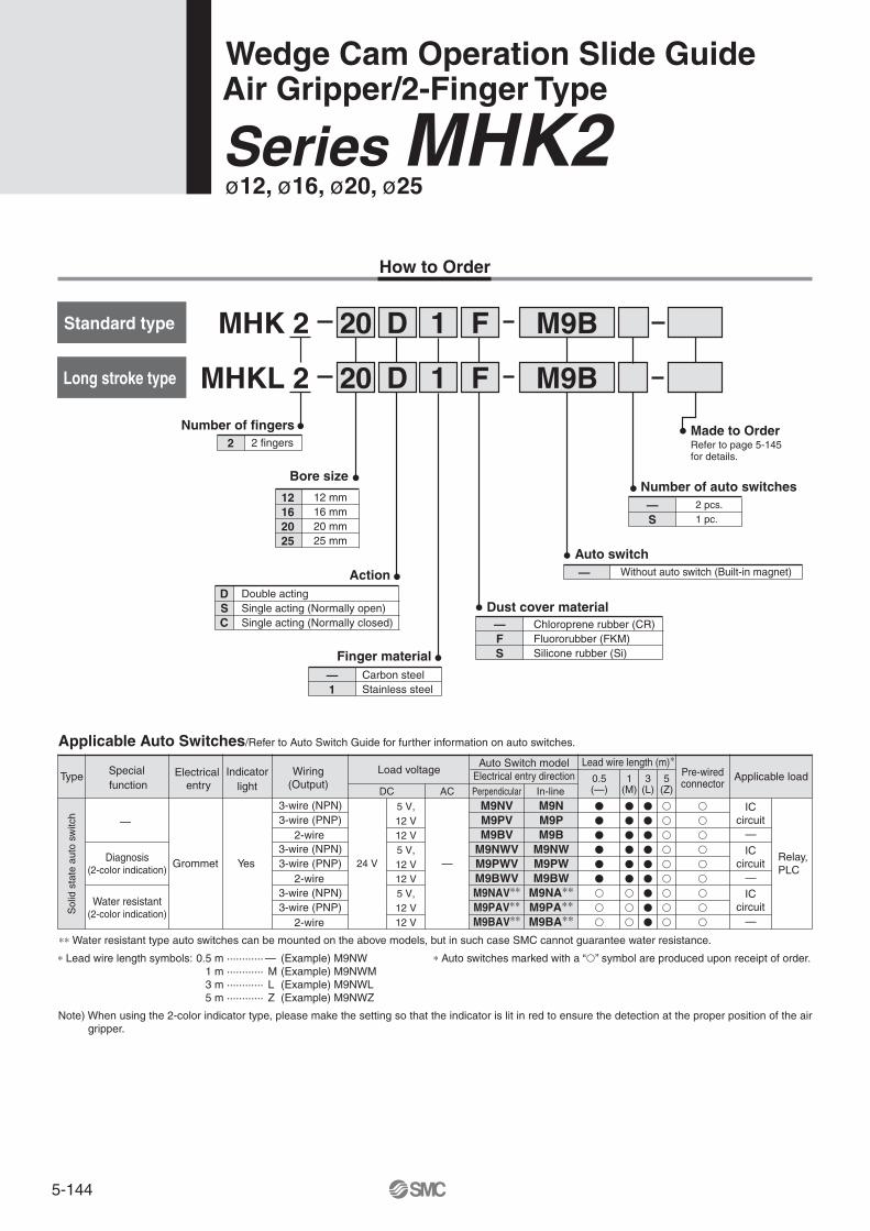
MHK 2 20
MHKL 2 20
D
D
1
1
F
F
—FS
—1
DSC
—
—
—
DC In-linePerpendicular
24 V
12 V
12 V
5 V,12 V
AC0.5(—)
1(M)
3(L)
M9NVM9PVM9BV
M9NWVM9PWVM9BWVM9NAV∗∗M9PAV∗∗M9BAV∗∗
M9NM9PM9B
M9NWM9PWM9BW
M9NA∗∗M9PA∗∗M9BA∗∗
5(Z)
5 V,12 V
M9B
M9B
Made to OrderRefer to page 5-145 for details.
—
Standard type
Long stroke type
2 pcs.1 pc.
Bore size
Number of fingers2 fingers
Number of auto switches
Auto switchWithout auto switch (Built-in magnet)
Dust cover materialChloroprene rubber (CR) Fluororubber (FKM) Silicone rubber (Si) Finger material
Carbon steelStainless steel
ActionDouble actingSingle acting (Normally open)Single acting (Normally closed)
Applicable Auto Switches/Refer to Auto Switch Guide for further information on auto switches.
—
Type Special function
Electrical entry
Indicatorlight
Wiring(Output)
Load voltage
Sol
id s
tate
aut
o sw
itch
Grommet Yes
Water resistant(2-color indication)
Diagnosis(2-color indication)
3-wire (NPN)3-wire (PNP)
2-wire
3-wire (NPN)3-wire (PNP)
2-wire
Lead wire length (m)∗Auto Switch modelElectrical entry direction Applicable loadPre-wired
connector
Relay,PLC
ICcircuit
—12 V
5 V,12 V
3-wire (NPN)3-wire (PNP)
2-wire
ICcircuit
ICcircuit
∗ Lead wire length symbols: 0.5 m ············ — (Example) M9NW 1 m ············ M (Example) M9NWM 3 m ············ L (Example) M9NWL 5 m ············ Z (Example) M9NWZ
∗∗ Water resistant type auto switches can be mounted on the above models, but in such case SMC cannot guarantee water resistance.
Wedge Cam Operation Slide GuideAir Gripper/2-Finger Type
Series MHK2ø12, ø16, ø20, ø25
Note) When using the 2-color indicator type, please make the setting so that the indicator is lit in red to ensure the detection at the proper position of the air gripper.
�
�
�
�
�
�
�
�
�
�
�
�
�
�
�
�
�
�
�
�
�
�
�
�
�
�
�
�
�
�
�
�
�
�
�
�
�
�
�
�
�
�
�
�
�
∗ Auto switches marked with a “�” symbol are produced upon receipt of order.
How to Order
5-145
MHK2-12S�
MHK2-16S�
MHK2-20S�
MHK2-25S�
MHK2-12C�
MHK2-16C�
MHK2-20C�
MHK2-25C�
12
16
20
25
12
16
20
25
9
23
34
58
12
25
44
73
4
6
10
14
4
6
10
14
9
14.6
16
19
9
14.6
16
19
13
20.6
26
33
13
20.6
26
33
76
114
237
443
76
115
237
443
120
MHK2-12D� 12 4 9 13 75
MHK2-16D� 16 6 14.6 20.6 113
MHK2-20D� 20 10 16 26 235
MHK2-25D� 25 14 19 33 440
MHKL2-12S�
MHKL2-16S�
MHKL2-20S�
MHKL2-25S�
MHKL2-12C�
MHKL2-16C�
MHKL2-20C�
MHKL2-25C�
12
16
20
25
12
16
20
25
9
17
32
53
11
22
40
63
11
14
18
22
11
14
18
22
9
14.6
16
19
9
14.6
16
19
20
28.6
34
41
20
28.6
34
41
105
165
314
565
105
166
314
565
90
MHKL2-12D� 12 11 9 20 104
MHKL2-16D� 16 14 14.6 28.6 164
MHKL2-20D� 20 18 16 34 312
MHKL2-25D� 25 22 19 41 562
L1
L2 L1
L2Series MHK2
Series MHKL2
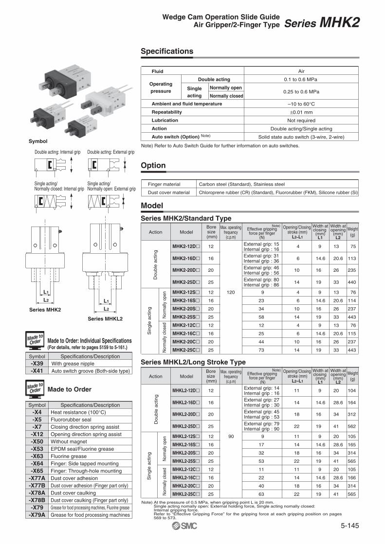
Specifications
Model
Option
Series MHKL2/Long Stroke Type
Series MHK2/Standard Type
Fluid Air
0.1 to 0.6 MPa
0.25 to 0.6 MPa
–10 to 60°C
±0.01 mm
Not required
Double acting/Single acting
Solid state auto switch (3-wire, 2-wire)
Operatingpressure
Double acting
Singleacting
Normally open
Normally closed
Note) Refer to Auto Switch Guide for further information on auto switches.
Ambient and fluid temperature
Repeatability
Lubrication
Action
Auto switch (Option) Note)
Finger material
Dust cover material
Carbon steel (Standard), Stainless steel
Chloroprene rubber (CR) (Standard), Fluororubber (FKM), Silicone rubber (Si)
ModelBoresize
(mm)
Max. operatingfrequency
(c.p.m)
Effective grippingforce per finger
(N)Action
Do
ub
le a
ctin
gS
ingle
act
ing
Nor
mal
ly o
pen
Nor
mal
ly c
lose
d
Opening/Closing stroke (mm)
L2–L1
Width atclosing (mm)
L1
Width atopening
(mm)L2
Weight(g)
Note)
External grip: 15Internal grip : 16External grip: 31Internal grip : 36External grip: 46Internal grip : 56External grip: 80Internal grip : 86
Double
act
ing
Sin
gle
act
ing
Nor
mal
ly o
pen
Nor
mal
ly c
lose
d
Width atclosing (mm)
L1
Width atopening
(mm)L2
ModelBoresize
(mm)
Max. operatingfrequency
(c.p.m)
Effective grippingforce per finger
(N)Action
Opening/Closing stroke (mm)
L2–L1
Weight(g)
Note)
External grip: 14Internal grip : 16External grip: 27Internal grip : 30External grip: 45Internal grip : 53External grip: 79Internal grip : 90
Note) At the pressure of 0.5 MPa, when gripping point L is 20 mm.Single acting nomally open: External holding force, Single acting nomally closed: Internal gripping force.Refer to “Effective Gripping Force” for the gripping force at each gripping position on pages 569 to 573.
Symbol
Double acting: Internal grip Double acting: External grip
Single acting/Normally closed: Internal grip
Single acting/Normally open: External grip
Series MHK2Wedge Cam Operation Slide GuideAir Gripper/2-Finger Type
Made to Order
Symbol Specifications/Description
Made to Order: Individual Specifications(For details, refer to pages 5159 to 5-161.)
Symbol Specifications/DescriptionWith grease nippleAuto switch groove (Both-side type)
-X39-X41
-X4-X5-X7-X12-X50-X53-X63-X64-X65
-X77A-X77B-X78A-X78B-X79
-X79A
Heat resistance (100°C)Fluororubber sealClosing direction spring assistOpening direction spring assistWithout magnetEPDM seal/Fluorine greaseFluorine greaseFinger: Side tapped mountingFinger: Through-hole mountingDust cover adhesionDust cover adhesion (Finger part only)Dust cover caulkingDust cover caulking (Finger part only)Grease for food processing machines, Fluorine greaseGrease for food processing machines
5-146
@0 e !8 !7 w
!9
t
y
!5
iu!6qr
o
!1!0
!2
!4 !3
CRFKMSi
MHK12-PSMHK-A1201P3318103P3318104P3318104-1
MHK2-J12MHK2-J12FMHK2-J12S
MHK16-PSMHK-A1601P3318203P3318204P3318204-1
MHK2-J16MHK2-J16FMHK2-J16S
MHK20-PSMHK-A2001P3318303P3318304P3318304-1
MHK2-J20MHK2-J20FMHK2-J20S
MHK25-PSMHK-A2501P3318403P3318404P3318404-1
MHK2-J25MHK2-J25FMHK2-J25S
MHK2-12� MHK2-16� MHK2-20� MHK2-25�
MHK-A1206
CRFKMSi
MHK12-PSMHK-A1201P3318111P3318112P3318112-1
MHKL2-J12MHKL2-J12FMHKL2-J12S
MHK16-PSMHK-A1601P3318211P3318212P3318212-1
MHKL2-J16MHKL2-J16FMHKL2-J16S
MHK20-PSMHK-A2001P3318311P3318312P3318312-1
MHKL2-J20MHKL2-J20FMHKL2-J20S
MHK25-PSMHK-A2501P3318411P3318412P3318412-1
MHKL2-J25MHKL2-J25FMHKL2-J25S
MHKL2-12� MHKL2-16� MHKL2-20� MHKL2-25�
MHK-A1206
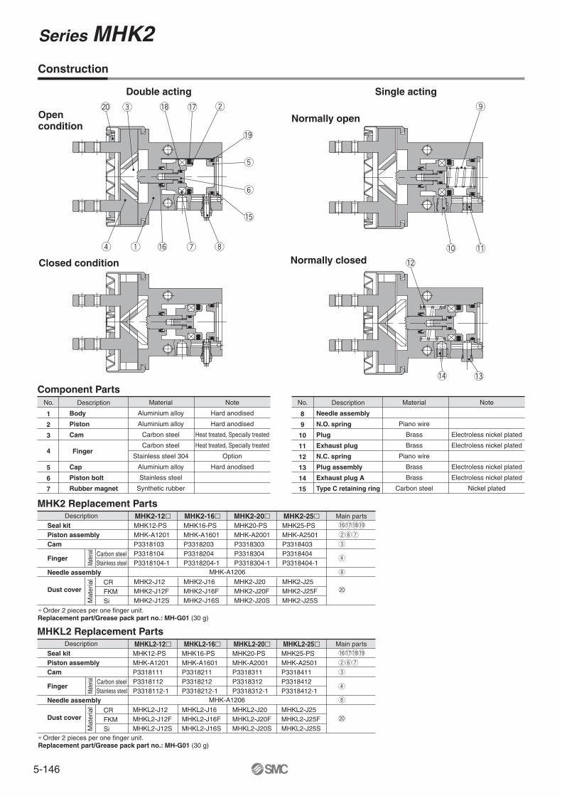
Construction
Double acting Single acting
Open condition
Closed condition
Normally open
Normally closed
No.
1
2
3
5
6
7
Description Material
Aluminium alloy
Aluminium alloy
Carbon steel
Carbon steel
Stainless steel 304
Aluminium alloy
Stainless steel
Synthetic rubber
Note
Hard anodised
Hard anodised
Heat treated, Specially treated
Heat treated, Specially treated
Option
Hard anodised
Component PartsNo.
8
9
10
11
12
13
14
15
Description
Needle assembly
N.O. spring
Plug
Exhaust plug
N.C. spring
Plug assembly
Exhaust plug A
Type C retaining ring
Material
Piano wire
Brass
Brass
Piano wire
Brass
Brass
Carbon steel
Note
Electroless nickel plated
Electroless nickel plated
Electroless nickel plated
Electroless nickel plated
Nickel plated
Finger4
MHK2 Replacement PartsDescription
Mat
eria
lMa
terial
Dust cover
Seal kitPiston assemblyCam
Finger
Needle assembly
Carbon steelStainless steel
Main parts
wyu
!6!7!8!9
e
r
i
@0
∗ Order 2 pieces per one finger unit. Replacement part/Grease pack part no.: MH-G01 (30 g)
∗ Order 2 pieces per one finger unit. Replacement part/Grease pack part no.: MH-G01 (30 g)
MHKL2 Replacement PartsDescription
Mat
eria
lMa
terial
Dust cover
Seal kitPiston assemblyCam
Finger
Needle assembly
Carbon steelStainless steel
Main parts
wyu
!6!7!8!9
e
r
i
@0
Body
Piston
Cam
Cap
Piston bolt
Rubber magnet
Series MHK2

5-147
20 30 40
20
30
40
50
60
50 60100
20 30 40
20
30
40
50
60
50 60100 0
20
100
80
60
40
100806040 40 60 80
40
60
80
100
120
100 120200
MHK2-25DMHKL2-16DMHKL2-20DMHKL2-25D
10
20
30
40
50
60
20 40 60 80
41
0
202010 10
Model Selection ExampleProcedure
Workpiece form:Diameter x Lengthø28 x 35 mm round bar
Confirmation of conditions Select possible points according to the work length
Selection of model from gripping force graph
Work mass: 0.17 kg
Gripping method: External gripping
Calculation of required gripping force
Workpiece diameter: From dimensions of model that has opening width 28 mm or more.
Guidelines for the selection of the gripper with respect to workpiece mass• Although conditions differ according to the
workpiece shape and the coefficient of friction between the attachments and the workpiece, select a model that can provide a gripping force of 10 to 20 times the workpiece mass, or more.
• If high acceleration, deceleration or impact forces are encountered during motion, a further margin of safety should be considered.
Ex.) For setting the gripping force to be at least 20 times the workpiece mass:
Required gripping force = 0.17 kg x 20 x 9.8 m/s2
≈ 33 N
• When MHKL2-20D is selected, the gripping force is determined to be 41N according to the gripping point distance 40 mm and the pressure (0.5 MPa).
• The gripping force is 24.5 times the workpiece mass meeting the guideline that gripping force should be more than 20.
MHKL2-20DExternal Gripping Force
Grip
ping
forc
e (
N)
Gripping point L (mm)
Gripping Point
Gripping point 40 mm
Operating pressure: 0.5 MPa
Pressure 0.6 MPa
0.5 MPa
0.4 MPa
0.3 MPa
0.2 MPa
L: Gripping point distanceH: Overhang distance
External grip
Series MHK2 Series MHKL2
L L
H H
Gripping point Gripping point L L
H H
Gripping point Gripping point
Internal grip
Series MHK2 Series MHKL2
• Proper gripping points should be selected in accordance with the operating pressure. The distance to the gripping point L and the overhang distance H should be within the limited range given in the graphs below.
• When the gripping point distance becomes large, the finger attachment applies an excessively large load to the finger sliding section, causing excessive play of the fingers and possibly leading to premature failure.
MHK2-12�MHKL2-12�
Gripping Point Range Limit
MHK2-16�MHKL2-16�
MHK2-20�MHKL2-20�
MHK2-25�MHKL2-25�
Note) Distance to the gripping point L of single acting type is shortened by spring return. Use air gripper within gripping force line shown for each pressure in effective gripping force graph.
0.3 MPa0.4 MPa
0.5 MPa0.6 MPa
Pressure 0.2 MPa0.3 MPa
0.4 MPa0.5 MPa
0.6 MPa
Pressure 0.2 MPa0.3 MPa
0.4 MPa
0.5 MPa
0.6 MPa
Pressure 0.2 MPa0.3 MPa
0.4
MPa
0.5
MPa
0.6
MPa
Pressure 0.2 MPa
Gripping point L [mm]
Ove
rhan
g di
stan
ce H
[mm
]
Gripping point L [mm]
Ove
rhan
g di
stan
ce H
[mm
]
Gripping point L [mm]
Ove
rhan
g di
stan
ce H
[mm
]
Gripping point L [mm]
Ove
rhan
g di
stan
ce H
[mm
]
Series MHK2 Wedge Cam Operation Slide Guide
Air Gripper (2 Finger)
5-148
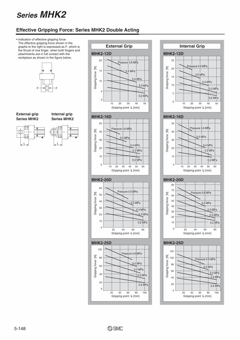
MHK2-12D
MHK2-16D
MHK2-20D
MHK2-25D
MHK2-12D
MHK2-16D
MHK2-20D
MHK2-25D
L L
F F
10 20 30 40
10
15
20
50
10 20 30 40 50 60
10
20
30
40
50
10
20
30
40
50
60
20 40 60 80
20
40
60
80
100
20 40 60 80 100
25
70
80
120
10 20 30 40
10
15
20
50
10 20 30 40 50 60
10
20
30
40
50
10
20
30
40
50
60
20 40 60 80
20
40
60
80
100
20 40 60 80 100
55
00
00
0
0
0
0
Effective Gripping Force: Series MHK2 Double Acting
• Indication of effective gripping force The effective gripping force shown in the graphs to the right is expressed as F, which is the thrust of one finger, when both fingers and attachments are in full contact with the workpiece as shown in the figure below.
External gripSeries MHK2
Internal gripSeries MHK2
External Grip Internal Grip
Pressure 0.6 MPa
0.5 MPa
0.4 MPa
0.3 MPa
0.2 MPa
Pressure 0.6 MPa
0.5 MPa
0.4 MPa
0.3 MPa
0.2 MPa
Pressure 0.6 MPa
0.5 MPa
0.4 MPa
0.3 MPa
0.2 MPa
Pressure 0.6 MPa
0.5 MPa
0.4 MPa
0.3 MPa
0.2 MPa
Pressure 0.6 MPa
0.5 MPa
0.4 MPa
0.3 MPa
0.2 MPa
Pressure 0.6 MPa
0.5 MPa
0.4 MPa
0.3 MPa
0.2 MPa
Pressure 0.6 MPa
0.5 MPa
0.4 MPa
0.3 MPa
0.2 MPa
Gripping point L [mm]
Grip
ping
forc
e [N
]
Gripping point L [mm]
Grip
ping
forc
e [N
]Gripping point L [mm]
Grip
ping
forc
e [N
]
Gripping point L [mm]G
rippi
ng fo
rce
[N]
Gripping point L [mm]
Grip
ping
forc
e [N
]
Gripping point L [mm]
Grip
ping
forc
e [N
]
Gripping point L [mm]
Grip
ping
forc
e [N
]
Gripping point L [mm]
Grip
ping
forc
e [N
]
Pressure 0.6 MPa
0.5 MPa
0.4 MPa
0.3 MPa
0.2 MPa
Series MHK2
5-149
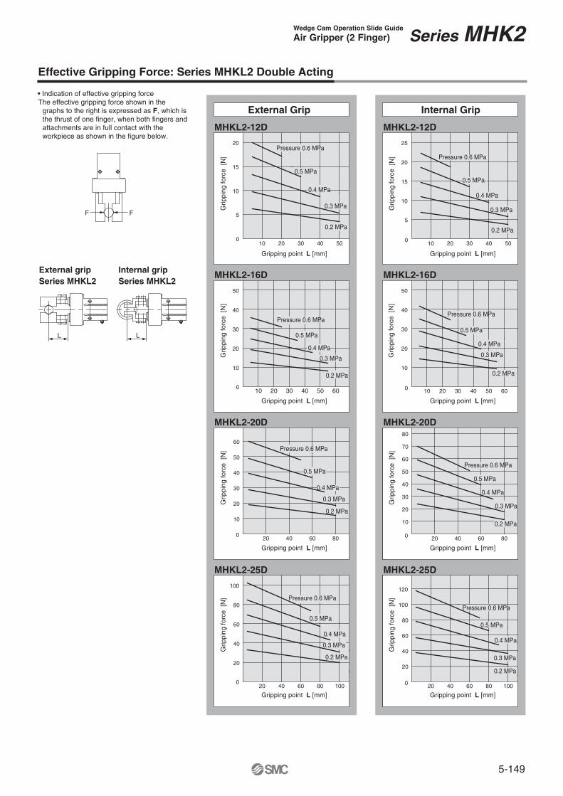
MHKL2-12D
MHKL2-16D
MHKL2-20D
MHKL2-25D
MHKL2-12D
MHKL2-16D
MHKL2-20D
MHKL2-25D
L
F F
L
10 20 30 40
10
15
20
50
10 20 30 40 50 60
10
20
30
40
50
10
20
30
40
50
60
20 40 60 80
20
40
60
80
100
20 40 60 80 100
25
70
80
120
10 20 30 40
10
15
20
50
10 20 30 40 50 60
10
20
30
40
50
10
20
30
40
50
60
20 40 60 80
20
40
60
80
100
20 40 60 80 100
55
0 0
0 0
0 0
0 0
Effective Gripping Force: Series MHKL2 Double Acting
• Indication of effective gripping force The effective gripping force shown in the
graphs to the right is expressed as F, which is the thrust of one finger, when both fingers and attachments are in full contact with the workpiece as shown in the figure below.
External gripSeries MHKL2
Internal gripSeries MHKL2
External Grip Internal Grip
Pressure 0.6 MPa
0.5 MPa
0.4 MPa
0.3 MPa
0.2 MPa
Pressure 0.6 MPa
0.5 MPa
0.4 MPa
0.3 MPa
0.2 MPa
Pressure 0.6 MPa
0.5 MPa
0.4 MPa
0.3 MPa
0.2 MPa
Pressure 0.6 MPa
0.5 MPa
0.4 MPa
0.3 MPa
0.2 MPa
Pressure 0.6 MPa
0.5 MPa
0.4 MPa
0.3 MPa
0.2 MPa
Pressure 0.6 MPa
0.5 MPa
0.4 MPa
0.3 MPa
0.2 MPa
Pressure 0.6 MPa
0.5 MPa
0.4 MPa
0.3 MPa
0.2 MPa
Gripping point L [mm]
Grip
ping
forc
e [N
]
Gripping point L [mm]
Grip
ping
forc
e [N
]
Gripping point L [mm] Gripping point L [mm]
Grip
ping
forc
e [N
]
Grip
ping
forc
e [N
]
Gripping point L [mm]
Grip
ping
forc
e [N
]
Gripping point L [mm]
Grip
ping
forc
e [N
]
Gripping point L [mm]
Grip
ping
forc
e [N
]
Gripping point L [mm]
Grip
ping
forc
e [N
]
Pressure 0.6 MPa
0.5 MPa
0.4 MPa
0.3 MPa
0.2 MPa
Series MHK2 Wedge Cam Operation Slide Guide
Air Gripper (2 Finger)
5-150
MHK2-12C
MHK2-16C
MHK2-20C
MHK2-25C
MHK2-12S
MHK2-16S
MHK2-20S
MHK2-25S
L
F F
L
10 20 30 40 50
15
10 20 30 40 50
10
20
30
40
10
20
30
40
50
60
20 40 60 80
10
60
20
40
60
80
100
20 40 60 80 100
10 20 30 40 50
10
15
20
10 20 30 40 50 60
10
20
30
40
10
20
30
40
50
20 40 60 80
20
40
60
80
100
20 40 60 80 100
60
70
80
5
0
5
0
0 0
0 0
0 0
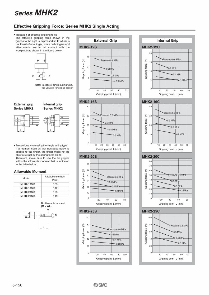
MHK2-12S/C
MHK2-16S/C
MHK2-20S/C
MHK2-25S/C
0.05
0.12
0.25
0.49
(N·m)
L
M
W
Effective Gripping Force: Series MHK2 Single Acting
External gripSeries MHK2
Internal gripSeries MHK2
• Precautions when using the single acting type:If a moment such as that illustrated below is applied to the finger, the finger might not be able to retract by the spring force alone.Therefore, make sure to use the air gripper within the allowable moment that is indicated in the table below.
Note) In case of single acting type, the value is for stroke center.
• Indication of effective gripping force The effective gripping force shown in the
graphs to the right is expressed as F, which is the thrust of one finger, when both fingers and attachments are in full contact with the workpiece as shown in the figure below.
Model Allowable moment
Allowable Moment
M: Allowable moment(M = WL)
Internal GripExternal Grip
0.5 MPa
0.4 MPa
0.3 MPa
0.5 MPa
0.4 MPa
0.3 MPa
0.5 MPa
0.4 MPa
0.3 MPa
0.5 MPa
0.4 MPa
0.3 MPa
0.5 MPa
0.4 MPa
0.3 MPa
0.5 MPa
0.4 MPa
0.5 MPa
0.4 MPa
0.3 MPa
0.5 MPa
0.4 MPa
0.3 MPa
Pressure 0.6 MPa Pressure 0.6 MPa
Pressure 0.6 MPaPressure 0.6 MPa
Pressure 0.6 MPaPressure 0.6 MPa
0.3 MPa
Pressure 0.6 MPa
Pressure 0.6 MPa
Grip
ping
forc
e (
N)
Gripping point L (mm)
Grip
ping
forc
e (
N)
Gripping point L (mm)
Grip
ping
forc
e (
N)
Gripping point L (mm)
Grip
ping
forc
e (
N)
Gripping point L (mm)
Grip
ping
forc
e (
N)
Gripping point L (mm)
Grip
ping
forc
e (
N)
Gripping point L (mm)
Grip
ping
forc
e (
N)
Gripping point L (mm)
Grip
ping
forc
e (
N)
Gripping point L (mm)
Series MHK2

5-151
MHKL2-12C
MHKL2-16C
MHKL2-20C
MHKL2-25C
MHKL2-12S
MHKL2-16S
MHKL2-20S
MHKL2-25S
L
F F
L
10
15
5
10 20 30 40 50
10
20
30
40
60
10
20
30
40
50
60
20 40 60 80
10 20 30 40 50
10
15
20
5
0 0
10 20 30 40 50 60
10
20
30
40
0 0
10
20
30
50
60
20 40 60 80
70
80
40
0 0
0 0
20
40
60
80
100
20 40 60 80 100
20
40
60
80
100
20 40 60 80 100
MHKL2-12S/C
MHKL2-16S/C
MHKL2-20S/C
MHKL2-25S/C
0.05
0.12
0.25
0.49
L
W
M
10 20 30 40 50
Effective Gripping Force: Series MHKL2 Single Acting
External gripSeries MHKL2
Internal gripSeries MHKL2
• Precautions when using the single acting type:If a moment such as that illustrated below is applied to the finger, the finger might not be able to retract by the spring force alone.Therefore, make sure to use the air gripper within the allowable moment that is indicated in the table below.
Note) In case of single acting type, the value is for stroke center.
• Indication of effective gripping force The effective gripping force shown in the
graphs to the right is expressed as F, which is the thrust of one finger, when both fingers and attachments are in full contact with the workpiece as shown in the figure below.
Model Allowable moment
Allowable Moment
(N·m)
M: Allowable moment(M = WL)
Internal GripExternal Grip
Grip
ping
forc
e (
N)
Gripping point L (mm)
Grip
ping
forc
e (
N)
Gripping point L (mm)
Grip
ping
forc
e (
N)
Gripping point L (mm)G
rippi
ng fo
rce
(N
)Gripping point L (mm)
Grip
ping
forc
e (
N)
Gripping point L (mm)
Grip
ping
forc
e (
N)
Gripping point L (mm)
Grip
ping
forc
e (
N)
Gripping point L (mm)
Grip
ping
forc
e (
N)
Gripping point L (mm)
0.5 MPa
0.4 MPa
0.3 MPa
0.5 MPa
0.4 MPa
0.3 MPa
0.5 MPa
0.4 MPa
0.3 MPa
0.5 MPa
0.4 MPa
0.3 MPa
0.5 MPa
0.4 MPa
0.3 MPa
0.5 MPa
0.4 MPa
0.3 MPa
0.5 MPa
0.4 MPa
0.3 MPa
0.5 MPa
0.4 MPa
0.3 MPa
Pressure 0.6 MPaPressure 0.6 MPa
Pressure 0.6 MPa
Pressure 0.6 MPa
Pressure 0.6 MPa Pressure 0.6 MPa
Pressure 0.6 MPa
Pressure 0.6 MPa
Series MHK2 Wedge Cam Operation Slide Guide
Air Gripper (2 Finger)
5-152
Series MHK2
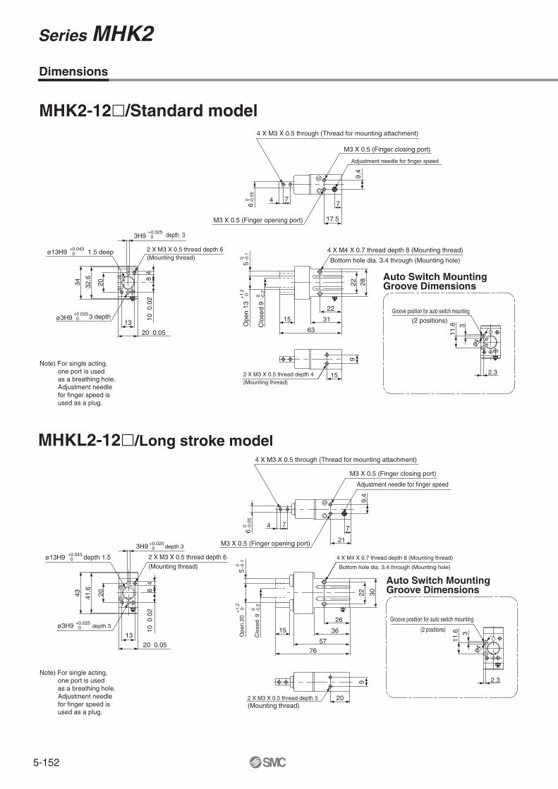
MHK2-12�/Standard model
Dimensions
15
9
2 X M3 X 0.5 thread depth 4(Mounting thread)
4 X M4 X 0.7 thread depth 8 (Mounting thread)
Bottom hole dia. 3.4 through (Mounting hole)
22 28
22
31
63
15
Clo
sed
9
5O
pen
13+
1.2
0 0 -0.2
0 -0.1
48
10 0
.02
13
20 0.05
32.6
34 20
ø13H9 1.5 deep+0.043 0
3H9 depth 3+0.025 0
2 X M3 X 0.5 thread depth 6(Mounting thread)
Groove position for auto switch mounting(2 positions)
3
11.6
2.3
Groove position for auto switch mounting
(2 positions)
MHKL2-12�/Long stroke model
ø3H9 3 depth+0.025 0
20
9
2 X M3 X 0.5 thread depth 5(Mounting thread)
4 X M4 X 0.7 thread depth 8 (Mounting thread)
Bottom hole dia. 3.4 through (Mounting hole)
22 30
26
36
57
15
76
Clo
sed
9
5O
pen
20+
1.2
0 0 -0.2
0 -0.1
ø13H9 depth 1.5+0.043 0
3H9 depth 3+0.025 0
2 X M3 X 0.5 thread depth 6(Mounting thread)
ø3H9 depth 3 +0.025 0
13
20 0.05
48
10 0
.02
41.6
43 20
3
11.6
2.3
ø4ø4
4 X M3 X 0.5 through (Thread for mounting attachment)
M3 X 0.5 (Finger closing port)
Adjustment needle for finger speed
7
17.5
4 7
6 0 -0
.05
M3 X 0.5 (Finger opening port)
9.4
S
4 X M3 X 0.5 through (Thread for mounting attachment)
M3 X 0.5 (Finger closing port)
Adjustment needle for finger speed
7
21M3 X 0.5 (Finger opening port)
9.4
S
4 7
6 0 -0
.05
Note) For single acting, one port is used as a breathing hole. Adjustment needle for finger speed is used as a plug.
Note) For single acting, one port is used as a breathing hole. Adjustment needle for finger speed is used as a plug.
Auto Switch MountingGroove Dimensions
Auto Switch MountingGroove Dimensions
5-153
Series MHK2 Wedge Cam Operation Slide Guide
Air Gripper (2 Finger)
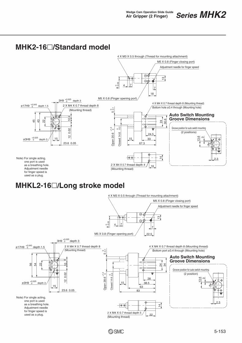
MHK2-16�/Standard model
MHKL2-16�/Long stroke model
16
142 X M4 X 0.7 thread depth 4(Mounting thread)
4 X M4 X 0.7 thread depth 8 (Mounting thread)Bottom port ø3.4 through (Mounting hole)
24 30.6
24.5
33
67.3
15
Clo
sed
14.6
5O
pen
20.6
+1.
2 0 0 -0
.2
0 -0.1
ø17H9 depth 1.5+0.043 0 2 X M4 X 0.7 thread depth 8
(Mounting thread)
ø3H9 depth 3 +0.025 0
3H9 depth 3+0.025 0
410
12 0
.02
15
23.6 0.05
4345 22
Groove position for auto switch mounting(2 positions)
3
13.6
2.3
ø4
313
.6
22
14
2 X M4 X 0.7 thread depth 5
(Mounting thread)
24 34
28
38.563
15
Clo
sed
14.6
5O
pen
28.6
+1.
2
0
0 -0.2
0 -0.1
4 X M4 X 0.7 thread depth 8 (Mounting thread)Bottom hole ø3.4 through (Mounting hole)
3H9 depth 3+0.025 0
ø17H9 depth 1.5 +0.043 0 2 X M4 X 0.7 thread depth 8
(Mounting thread)
ø3H9 depth 3+0.025 0
410
12 0
.02
5456 22
Groove position for auto switch mounting(2 position)
2.3
15
23.6 0.05 83
ø4
4 X M3 X 0.5 through (Thread for mounting attachment)
M5 X 0.8 (Finger closing port)
Adjustment needle for finger speed
M5 X 0.8 (Finger opening port)
7
18
8 0 -0
.05
4 7
13
S0
4 X M3 X 0.5 through (Thread for mounting attachment)
M5 X 0.8 (Finger closing port)
Adjustment needle for finger speed
M5 X 0.8 (Finger opening port)
4 7
8 0 -0
.05
13
SO
22.5
7
Note) For single acting, one port is used as a breathing hole. Adjustment needle for finger speed is used as a plug.
Note) For single acting, one port is used as a breathing hole. Adjustment needle for finger speed is used as a plug.
Auto Switch MountingGroove Dimensions
Auto Switch MountingGroove Dimensions

5-154
Series MHK2
13 . 5
6870 32
MHK2-20� /Standard model
Dimensions
MHKL2-20�/Long stroke model
202 X M5 X 0.8 thread depth 8(Mounting thread)
18.6
4 X M5 X 0.8 thread depth 10 (Mounting thread)Bottom hole ø4.3 through (Mounting hole)
30 42
29
40
84.8
21
Clos
ed 1
6
8O
pen
26+
1.2
0 0 -0.2
0 -0.1
ø21H9 depth 1.5+0.052 0 2 X M5 X 0.8 thread depth 10
(Mounting thread)
ø4H9 depth 4+0.030 0
4H9 depth 4+0.030 0
516
0.0
2
1827.6 0.05
5860 32
3
15
ø4
2.5
ø21H9 depth 1.5+0.052 0
2 X M5 X 0.8 thread depth 10(Mounting thread)
ø4H9 depth 4+0.030 0
4H9 depth1.5+0.030 0
1827.6 0.05
2 X M5 X 0.8 thread depth 8(Mounting thread)
18.6
24
4 X M5 X 0.8 thread depth 10 (Mounting thread)Bottom hole ø4.3 through (Mounting hole)
30 46
32
44.5
100
20
Clo
sed
16
8O
pen
34+
1.2
0 0 -0
.2
0 -0.1
315
ø4
Groove position for auto switch mounting(2 positions)
2.5
513
.516
0.0
2
73.5
4 X M4 X 0.7 through(Thread for mounting attachment)
M5 X 0.8 (Finger closing port)
Adjustment needle for finger speed
M5 X 0.8 (Finger opening port)
5 9
10 0 -0
.05
7.5
21
15
SO
4 X M4 X 0.7 through(Thread for mounting attachment)
M5 X 0.8 (Finger closing port)
Adjustment needle for finger speed
M5 X 0.8 (Finger opening port)
5 9
10 0 -0
.05
7.5
26.5
15
SO
Note) For single acting, one port is used as a breathing hole. Adjustment needle for finger speed is used as a plug.
Note) For single acting, one port is used as a breathing hole. Adjustment needle for finger speed is used as a plug.
Auto Switch MountingGroove Dimensions
Auto Switch MountingGroove Dimensions

5-155
Series MHK2 Wedge Cam Operation Slide Guide
Air Gripper (2 Finger)
MHK2-25�/Standard model
MHKL2-25�/Long stroke model
2 X M6 X 1 thread depth 10(Mounting thread)
22
22
4 X M6 X 1 thread depth 12 (Mounting thread) Bottom hole ø5.1 through (Mounting hole)
36 52
30
47.2
102.7
26Clos
ed 19
10O
pen
33+
1.2
0 0 -0.2
0 -0.1
ø26H9 depth 1.5+0.052 0 2 X M6 X 1 thread depth 12
(Mounting thread)
ø4H9 depth 4+0.030 0
2233.6 0.05
71.6
74 40
517
.520
0.0
2
4H9 depth 4+0.030 0
Groove position for auto switch mounting(2 positions)
3
16 ø4
2.3
22
302 X M6 X 1 thread depth 10(Mounting thread)
4 X M6 X 1 depth 12 (Mounting thread)
Bottom hole ø5.1 through (Mounting hole)
36 56
38
53.5
121
Clos
ed 1
9
10O
pen
41+
1.2
0
0 -0.2
0 -0.1
ø26H9 depth 1.5+0.052 0 2 X M6 X 1 thread depth 12
(Mounting thread)
ø4H9 depth 4+0.030 0
517
.520
0.0
2
81.6
84 40
2233.6 0.05
4H9 depth 4+0.030 0
Groove position for auto switch mounting
(2 positions)
3
16 ø4
2.3
88.525
4 X M5 X 0.8 through (Thread for mounting attachment)
M5 X 0.8 (Finger closing port)
Adjustment needle for finger speed
M5 X 0.8 (Finger opening port)
6 12
12 0 -0
.05
20
23
8
SO
4 X M5 X 0.8 through (Thread for mounting attachment)
M5 X 0.8 (Finger closing port)
Adjustment needle for finger speed
M5 X 0.8 (Finger opening port)8
30
6 12
12 0 -0
.05
20
Note) For single acting, one port is used as a breathing hole. Adjustment needle for finger speed is used as a plug.
Note) For single acting, one port is used as a breathing hole. Adjustment needle for finger speed is used as a plug.
Auto Switch MountingGroove Dimensions
Auto Switch MountingGroove Dimensions
5-156
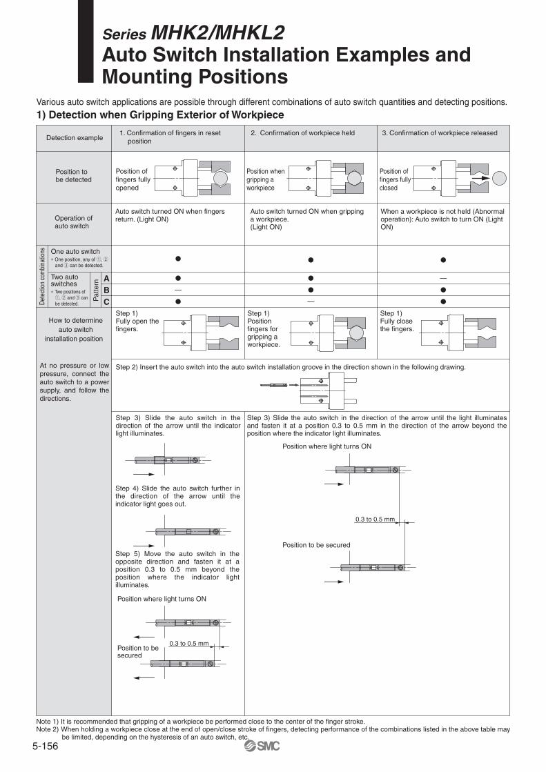
Position of fingers fully opened
Position when gripping a workpiece
Position of fingers fully closed
Detection example
One auto switch∗ One position, any of q, w and e can be detected.
Two auto switches∗ Two positions of q, w and e can be detected.
How to determineauto switch
installation position
Dete
ctio
n co
mbi
natio
ns
Pat
tern
Step 2) Insert the auto switch into the auto switch installation groove in the direction shown in the following drawing.At no pressure or low pressure, connect the auto switch to a power supply, and follow the directions.
When a workpiece is not held (Abnormal operation): Auto switch to turn ON (Light ON)
1. Confirmation of fingers in reset position
2. Confirmation of workpiece held 3. Confirmation of workpiece released
Step 1)Fully open the fingers.
Step 1)Position fingers for gripping a workpiece.
Step 1)Fully close the fingers.
Position tobe detected
Operation ofauto switch
Auto switch turned ON when fingers return. (Light ON)
Auto switch turned ON when gripping a workpiece. (Light ON)
Step 3) Slide the auto switch in the direction of the arrow until the indicator light illuminates.
Step 4) Slide the auto switch further in the direction of the arrow until the indicator light goes out.
Step 5) Move the auto switch in the opposite direction and fasten it at a position 0.3 to 0.5 mm beyond the position where the indicator light illuminates.
Step 3) Slide the auto switch in the direction of the arrow until the light illuminates and fasten it at a position 0.3 to 0.5 mm in the direction of the arrow beyond the position where the indicator light illuminates.
Position where light turns ON
Position to be secured
Note 1) It is recommended that gripping of a workpiece be performed close to the center of the finger stroke.Note 2) When holding a workpiece close at the end of open/close stroke of fingers, detecting performance of the combinations listed in the above table may
be limited, depending on the hysteresis of an auto switch, etc.
Position where light turns ON
Position to be secured
0.3 to 0.5 mm
0.3 to 0.5 mm
Various auto switch applications are possible through different combinations of auto switch quantities and detecting positions.
1) Detection when Gripping Exterior of Workpiece
Series MHK2/MHKL2Auto Switch Installation Examples and Mounting Positions
ABC
—
—
—
5-157
One auto switch∗ One position, any of q, w and e can be detected.
Two auto switches∗ Two positions of q, w and e can be detected.De
tect
ion
com
bina
tions
Pat
tern
ABC
Position of fingers fully closed
Position when gripping a workpiece
Position of fingers fully opened
Detection example
How to determineauto switch
installation position
Step 2) Insert the auto switch into the auto switch installation groove in the direction shown in the following drawing.At no pressure or low pressure, connect the auto switch to a power supply, and follow the directions.
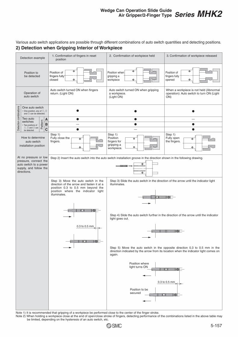
When a workpiece is not held (Abnormal operation): Auto switch to turn ON (Light ON)
1. Confirmation of fingers in reset position
2. Confirmation of workpiece held 3. Confirmation of workpiece released
Step 1)Fully close the fingers.
Step 1)Position fingers for gripping a workpiece.
Step 1)Fully open the fingers.
Position tobe detected
Operation ofauto switch
Auto switch turned ON when fingers return. (Light ON)
Auto switch turned ON when gripping a workpiece. (Light ON)
Note 1) It is recommended that gripping of a workpiece be performed close to the center of the finger stroke.Note 2) When holding a workpiece close at the end of open/close stroke of fingers, detecting performance of the combinations listed in the above table may
be limited, depending on the hysteresis of an auto switch, etc.
Various auto switch applications are possible through different combinations of auto switch quantities and detecting positions.
2) Detection when Gripping Interior of Workpiece
Step 3) Move the auto switch in the direction of the arrow and fasten it at a position 0.3 to 0.5 mm beyond the position where the indicator light illuminates.
Step 3) Slide the auto switch in the direction of the arrow until the indicator light illuminates.
Position where light turns ON
Position to be secured
Step 4) Slide the auto switch further in the direction of the arrow until the indicator light goes out.
Step 5) Move the auto switch in the opposite direction 0.3 to 0.5 mm in the direction indicated by the arrow from its location when the indicator light comes on again.
0.3 to 0.5 mm
0.3 to 0.5 mm
Series MHK2Wedge Can Operation Slide GuideAir Gripper/2-Finger Type
—
—
—

5-1585-158
Auto Switch Hysteresis Auto Switch Mounting
MHK2-12�
MHK2-16�
MHK2-20�
MHK2-25�
In-line electrical entry type Perpendicular electrial entry type
L
—
—
—
1
—
—
—
—
—
3
—
3
—
1
—
2
Protrusion of Auto Switch from Edge of Body
—
5
—
5
—
3
—
4
MHKL2-12�
MHKL2-16�
MHKL2-20�
MHKL2-25�
—
—
—
1
—
—
—
—
—
3
—
3
—
1
—
1
—
5
—
5
—
3
—
3
LL
S O
D-M9�D-M9�W
D-M9�VD-M9�WV
Perpendicular electrial entry type
—
3
—
3
—
1
—
2
—
3
—
3
—
1
—
1
D-M9�AVD-M9�A
Auto switches have hysteresis similar to micro switches. Use the table below as a guide when adjusting auto switch positions, etc.
Auto switch operating position (ON)
Hysteresis
Auto switch return position (OFF)
Flat head watchmaker’sscrewdriver
Auto switch
Auto switch mounting screwM2.5 x 4L
ø5 to ø6
To set the auto switch, insert the auto switch into the installation groove of the gripper from the direction indicated in the following drawing.After setting the position, tighten the attached auto switch mounting set screw with a flat head watchmaker’s screwdriver.
Note) Use a watchmaker’s screwdriver with a grip diameter of 5 to 6 mm to tighten the auto switch mounting screw.
The tightening torque should be about 0.05 to 0.15 N·m.
The amount of auto switch protrusion from the body’s end surface is as shown in the table below.Use the table as a guideline for mounting.
Lead wire Lateral type Lead wire
Vertical type
1 mm or more
Space
(mm)
Note) When auto switch for MHK2, MHKL2 is set on mounting side as figure below, allow for at least 1 mm on mounting plate since the auto switch is protruded from edge of gripper.
Note) There is no protrusion if no values are entered in the table.
Open
Closed
Open
Closed
Open
Closed
Open
Closed
Open
Closed
Open
Closed
Open
Closed
Open
Closed
Lead wire typeAuto switch model
Finger position Air gripper model
Series MHK2
0.1
0.1
0.3
0.2
Auto switchD-M9�(V)
D-M9�A(V)
M9�W(V)
MHK�2-12
MHK�2-16
MHK�2-20
MHK�2-25
Max. hysteresis (mm)
Model

5-1595-159
Series MHK2Made to Order: Individual Specifications 1
AGrease cup
1 -X39
16, 20, 25Double acting, Single acting (Normally open, Normally closed)
MHK standard grease (MH-G01)Refer to the dimensions and figure below.
Same as the standard type
ActionLubricant greaseGrease nipple position
Bore size (mm)
Specifications/dimensionsother than the above
Series MHK2Series MHKL2
Model AMHK2-16���-X39MHK2-20���-X39MHK2-25���-X39MHKL2-16���-X39MHKL2-20���-X39MHKL2-25���-X39
30.544.545364247.5
(mm)
MHKHow to Order
Specifications
With Grease NippleSymbol
Lubrication from grease cup to interior is possible.
X39With Grease Nipple
Standard part number
Note 1) Fill lubricant to the bearing from the grease cup in order to prevent foreign particles from getting in. The use of special grease MH-G01 for MHK is recommended.
Note 2) Not compatible with ø12.
Dimensions (Dimensions other than specified below are the same as the standard type.)
5-1605-160
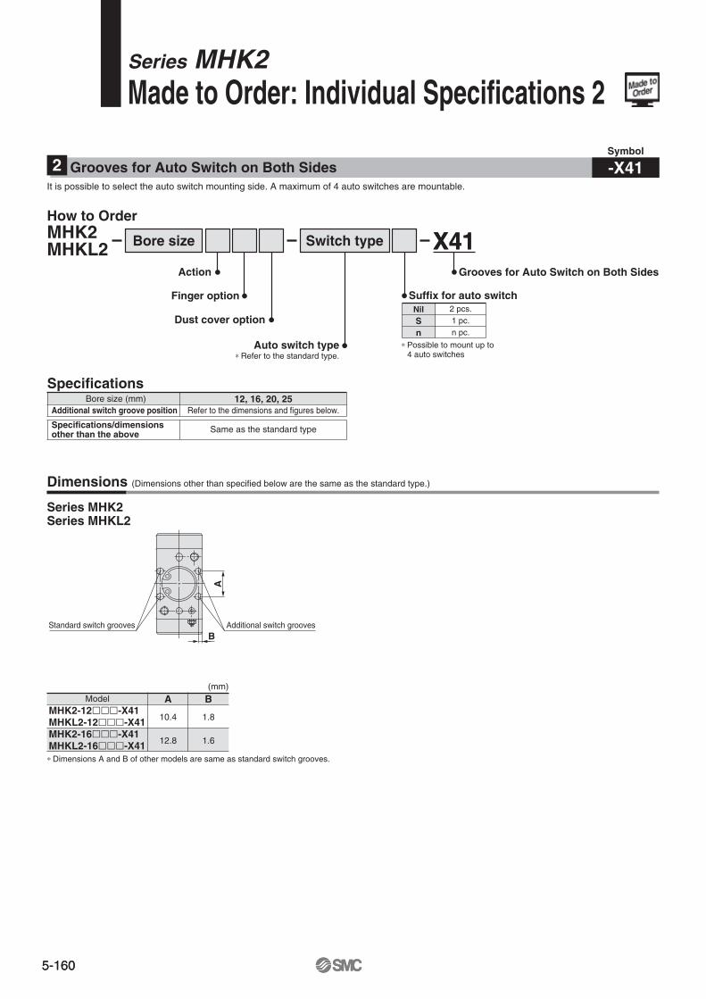
∗ Dimensions A and B of other models are same as standard switch grooves.
X41Grooves for Auto Switch on Both Sides
Series MHK2Made to Order: Individual Specifications 2
B
A
Additional switch groovesStandard switch grooves
2 -X41
Specifications12, 16, 20, 25
Refer to the dimensions and figures below.
Same as the standard type
Additional switch groove positionBore size (mm)
Specifications/dimensionsother than the above
Model AMHK2-12���-X41MHKL2-12���-X41MHK2-16���-X41MHKL2-16���-X41
10.4
12.8
B
1.8
1.6
(mm)
X41
Auto switch type∗ Refer to the standard type.
Action
Finger option Suffix for auto switch
Dust cover option
Bore size Switch typeMHK2MHKL2
NilSn
2 pcs.1 pc.n pc.
∗ Possible to mount up to 4 auto switches
Grooves for Auto Switch on Both SidesSymbol
It is possible to select the auto switch mounting side. A maximum of 4 auto switches are mountable.
Series MHK2Series MHKL2
Dimensions (Dimensions other than specified below are the same as the standard type.)
How to Order
5-1615-161
Attachment
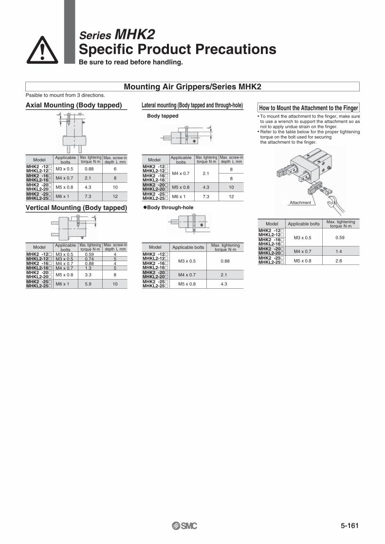
Mounting Air Grippers/Series MHK2
How to Mount the Attachment to the Finger
Pssible to mount from 3 directions.
Model Applicablebolts
Max. screw-indepth L mm
M3 x 0.5MHK2L-12�MHKL2-12�MHK2L-16�MHKL2-16�MHK2L-20�MHKL2-20�MHK2L-25�MHKL2-25�
M4 x 0.7
M5 x 0.8
M6 x 1
M3 x 0.5M3 x 0.5
0.88
2.1
4.3
7.3
6
8
10
12
MHK2L-12�
MHK2L-16�MHKL2-12�
MHKL2-16�MHK2L-20�MHKL2-20�MHK2L-25�MHKL2-25�
0.59
0.880.74
1.3
3.3
5.9
M5 x 0.8
M6 x 1
4
45
5
8
10
M4 x 0.7M4 x 0.7
M4 x 0.7
MHK2L-12�MHKL2-12�MHK2L-16�MHKL2-16�MHK2L-20�MHKL2-20�MHK2L-25�MHKL2-25�
M5 x 0.8
M6 x 1
2.1
4.3
7.3
8
8
10
12
MHK2L-12�MHKL2-12�MHK2L-16�MHKL2-16�MHK2L-20�MHKL2-20�MHK2L-25�MHKL2-25�
0.88
2.1
4.3
M4 x 0.7
M5 x 0.8
M3 x 0.5
MHK2L-12�MHKL2-12�MHK2L-16�MHKL2-16�MHK2L-20�MHKL2-20�MHK2L-25�MHKL2-25�
0.59
1.4
2.8
M4 x 0.7
M5 x 0.8
M3 x 0.5
Axial Mounting (Body tapped)
Vertical Mounting (Body tapped)
Lateral mounting (Body tapped and through-hole)
Body tapped
Body through-hole
Model
Model
Model
Model
Applicablebolts
Applicablebolts Applicable bolts
Applicable bolts
Max. screw-indepth L mm
Max. tighteningtorque N ⋅m
Max. tighteningtorque N ⋅m
Max. tighteningtorque N ⋅m
Max. tighteningtorque N ⋅m
Max. tighteningtorque N ⋅m
Max. screw-indepth L mm
To mount the attachment to the finger, make sure to use a wrench to support the attachment so asnot to apply undue strain on the finger.Refer to the table below for the proper tightening torque on the bolt used for securing the attachment to the finger.
Series MHK2Specific Product PrecautionsBe sure to read before handling.