Embed Size (px)
Citation preview

Gigabit Ethernet SWITCH
SF-0422G/SF-0446G

Management Guide
Gigabit Ethernet SwitchLayer 2 Standalone Switch withwith 22/46 10/100BASE-TX (RJ-45) Ports, and 4 Combination Gigabit (RJ-45/SFP) Ports
Managment Guide Version 1.0 SF-0422G, SF-0446G

E112009-MW-R01November, 2009
About This Guide
PurposeThis guide gives specific information on how to operate and use the management functions of the switch.
AudienceThe guide is intended for use by network administrators who are responsible for operating and maintaining network equipment; consequently, it assumes a basic working knowledge of general switch functions, the Internet Protocol (IP), and Simple Network Management Protocol (SNMP).
ConventionsThe following conventions are used throughout this guide to show information:
Note: Emphasizes important information or calls your attention to related features or instructions.
Caution: Alerts you to a potential hazard that could cause loss of data, or damage the system or equipment.
Warning: Alerts you to a potential hazard that could cause personal injury.
Related PublicationsThe following publication details the hardware features of the switch, including the physical and performance-related characteristics, and how to install the switch:
The Installation Manual
Also, as part of the switch’s software, there is an online web-based help that describes all management related features.
Revision HistoryThis section summarizes the changes in each revision of this guide.
September 2009 RevisionThis is the first revision of this guide.
v

vi
Contents
Chapter 1: Introduction 1-1Key Features 1-1Description of Software Features 1-2System Defaults 1-6
Chapter 2: Initial Configuration 2-1Connecting to the Switch 2-1
Configuration Options 2-1Required Connections 2-2Remote Connections 2-3
Basic Configuration 2-3Console Connection 2-3Setting Passwords 2-4Setting an IP Address 2-4
Manual Configuration 2-4Dynamic Configuration 2-5
Enabling SNMP Management Access 2-6Community Strings (for SNMP version 1 and 2c clients) 2-6Trap Receivers 2-7Configuring Access for SNMP Version 3 Clients 2-8
Managing System Files 2-8Saving Configuration Settings 2-9
Chapter 3: Configuring the Switch 3-1Using the Web Interface 3-1Navigating the Web Browser Interface 3-2
Home Page 3-2Configuration Options 3-3Panel Display 3-3Main Menu 3-4
Basic Configuration 3-11Displaying System Information 3-11Displaying Switch Hardware/Software Versions 3-13Displaying Bridge Extension Capabilities 3-15Setting the Switch’s IP Address 3-16
Manual Configuration 3-17Using DHCP/BOOTP 3-18
Enabling Jumbo Frames 3-19Managing Firmware 3-20
Downloading System Software from a Server 3-20
vii
Contents
Saving or Restoring Configuration Settings 3-22Downloading Configuration Settings from a Server 3-23
Console Port Settings 3-24Telnet Settings 3-26Configuring Event Logging 3-28
System Log Configuration 3-28Remote Log Configuration 3-29Displaying Log Messages 3-31Simple Mail Transfer Protocol 3-31
Resetting the System 3-33Setting the System Clock 3-34
Setting the Time Manually 3-34Configuring SNTP 3-34Setting the Time Zone 3-35
Simple Network Management Protocol 3-36Enabling the SNMP Agent 3-38Setting Community Access Strings 3-38Specifying Trap Managers and Trap Types 3-39Configuring SNMPv3 Management Access 3-42
Setting the Local Engine ID 3-42Specifying a Remote Engine ID 3-43Configuring SNMPv3 Users 3-44Configuring Remote SNMPv3 Users 3-46Configuring SNMPv3 Groups 3-48Setting SNMPv3 Views 3-51
User Authentication 3-53Configuring User Accounts 3-53Configuring Local/Remote Logon Authentication 3-55Configuring Encryption Keys 3-58AAA Authorization and Accounting 3-60
Configuring AAA RADIUS Group Settings 3-61Configuring AAA TACACS+ Group Settings 3-62Configuring AAA Accounting 3-62AAA Accounting Update 3-64AAA Accounting 802.1X Port Settings 3-65AAA Accounting Exec Command Privileges 3-66AAA Accounting Exec Settings 3-67AAA Accounting Summary 3-67Authorization Settings 3-69Authorization EXEC Settings 3-70Authorization Summary 3-71
Configuring HTTPS 3-72Replacing the Default Secure-site Certificate 3-73
Configuring the Secure Shell 3-74Generating the Host Key Pair 3-76
viii
Contents
Configuring the SSH Server 3-78Configuring 802.1X Port Authentication 3-79
Displaying 802.1X Global Settings 3-80Configuring 802.1X Global Settings 3-81Configuring Port Settings for 802.1X 3-82Displaying 802.1X Statistics 3-85
Filtering IP Addresses for Management Access 3-86General Security Measures 3-88
Configuring Port Security 3-89Network Access (MAC Address Authentication) 3-90
Configuring the MAC Authentication Reauthentication Time 3-91Configuring MAC Authentication for Ports 3-92Displaying Secure MAC Address Information 3-93
MAC Authentication 3-95Configuring MAC Authentication Parameters for Ports 3-95
Access Control Lists 3-96Setting the ACL Name and Type 3-96Configuring a Standard IP ACL 3-98Configuring an Extended IP ACL 3-99Configuring a MAC ACL 3-101Binding a Port to an Access Control List 3-103
DHCP Snooping 3-104DHCP Snooping Configuration 3-105DHCP Snooping VLAN Configuration 3-106DHCP Snooping Information Option Configuration 3-107DHCP Snooping Port Configuration 3-108DHCP Snooping Binding Information 3-109
IP Source Guard 3-110Configuring Ports for IP Source Guard 3-110Configuring Static Binding for IP Source Guard 3-112Displaying Information for Dynamic IP Source Guard Bindings 3-114
Port Configuration 3-115Displaying Connection Status 3-115Configuring Interface Connections 3-117Creating Trunk Groups 3-119
Statically Configuring a Trunk 3-120Enabling LACP on Selected Ports 3-122Configuring Parameters for LACP Group Members 3-123Displaying LACP Port Counters 3-125Displaying LACP Settings and Status for the Local Side 3-127Displaying LACP Settings and Status for the Remote Side 3-129
Setting Broadcast Storm Thresholds 3-130Setting Multicast Storm Thresholds 3-132Setting Unknown Unicast Storm Thresholds 3-133Configuring Local Port Mirroring 3-135
ix
Contents
Configuring Remote Port Mirroring 3-136Configuring Rate Limits 3-140
Rate Limit Configuration 3-140Showing Port Statistics 3-141
Address Table Settings 3-146Setting Static Addresses 3-146Displaying the Address Table 3-147Changing the Aging Time 3-148
Spanning Tree Algorithm Configuration 3-149Displaying Global Settings 3-151Configuring Global Settings 3-154Displaying Interface Settings 3-158Configuring Interface Settings 3-161Configuring Multiple Spanning Trees 3-165Displaying Interface Settings for MSTP 3-168Configuring Interface Settings for MSTP 3-170
VLAN Configuration 3-171IEEE 802.1Q VLANs 3-171
Enabling or Disabling GVRP (Global Setting) 3-174Displaying Basic VLAN Information 3-175Displaying Current VLANs 3-176Creating VLANs 3-177Adding Static Members to VLANs (VLAN Index) 3-180Adding Static Members to VLANs (Port Index) 3-182Configuring VLAN Behavior for Interfaces 3-183
Configuring IEEE 802.1Q Tunneling 3-185Enabling QinQ Tunneling on the Switch 3-188Adding an Interface to a QinQ Tunnel 3-189
Traffic Segmentation 3-192Configuring Global Settings for Traffic Segmentation 3-192Configuring Traffic Segmentation Uplinks and Downlinks 3-193
Private VLANs 3-194Displaying Current Private VLANs 3-194Configuring Private VLANs 3-195Associating VLANs 3-196Displaying Private VLAN Interface Information 3-197Configuring Private VLAN Interfaces 3-198
Protocol VLANs 3-199Configuring Protocol VLAN Groups 3-200Mapping Protocols to VLANs 3-201
Class of Service Configuration 3-203Layer 2 Queue Settings 3-203
Setting the Default Priority for Interfaces 3-203Mapping CoS Values to Egress Queues 3-205Selecting the Queue Mode 3-207
x
Contents
Setting the Service Weight for Traffic Classes 3-208Layer 3/4 Priority Settings 3-209
Mapping Layer 3/4 Priorities to CoS Values 3-209Selecting IP Precedence/DSCP Priority 3-209Mapping IP Precedence 3-210Mapping DSCP Priority 3-211Mapping IP Port Priority 3-213
Quality of Service 3-214Configuring Quality of Service Parameters 3-215
Configuring a Class Map 3-215Creating QoS Policies 3-218Attaching a Policy Map to Ingress Queues 3-221
Multicast Filtering 3-222Layer 2 IGMP (Snooping and Query) 3-223
Configuring IGMP Snooping and Query Parameters 3-224Enabling IGMP Immediate Leave 3-226Displaying Interfaces Attached to a Multicast Router 3-228Specifying Static Interfaces for a Multicast Router 3-229Displaying Port Members of Multicast Services 3-230Assigning Ports to Multicast Services 3-231
IGMP Filtering and Throttling 3-232Enabling IGMP Filtering and Throttling 3-232Configuring IGMP Filter Profiles 3-233Configuring IGMP Filtering and Throttling for Interfaces 3-235
Multicast VLAN Registration 3-237Configuring Global MVR Settings 3-238Displaying MVR Interface Status 3-240Displaying Port Members of Multicast Groups 3-241Configuring MVR Interface Status 3-242Assigning Static Multicast Groups to Interfaces 3-244
Configuring Domain Name Service 3-245Configuring General DNS Service Parameters 3-245Configuring Static DNS Host to Address Entries 3-247Displaying the DNS Cache 3-249
Switch Clustering 3-250Cluster Configuration 3-250Cluster Member Configuration 3-252Displaying Information on Cluster Members 3-253Cluster Candidate Information 3-254
Chapter 4: Command Line Interface 4-1Using the Command Line Interface 4-1
Accessing the CLI 4-1Console Connection 4-1
xi
Contents
Telnet Connection 4-2Entering Commands 4-3
Keywords and Arguments 4-3Minimum Abbreviation 4-3Command Completion 4-3Getting Help on Commands 4-3Showing Commands 4-4Partial Keyword Lookup 4-5Negating the Effect of Commands 4-5Using Command History 4-5Understanding Command Modes 4-6Exec Commands 4-6Configuration Commands 4-7Command Line Processing 4-9
Command Groups 4-10General Commands 4-11
enable 4-11disable 4-12configure 4-12show history 4-13reload 4-13prompt 4-14end 4-14exit 4-15quit 4-15
System Management Commands 4-16Device Designation Commands 4-16
hostname 4-16System Status Commands 4-17
show startup-config 4-17show running-config 4-18show system 4-21show users 4-21show version 4-22
Frame Size Commands 4-23jumbo frame 4-23
File Management Commands 4-24copy 4-25delete 4-28dir 4-28whichboot 4-29boot system 4-30
Line Commands 4-31line 4-31login 4-32
xii
Contents
password 4-33timeout login response 4-34exec-timeout 4-34password-thresh 4-35silent-time 4-36databits 4-36parity 4-37speed 4-38stopbits 4-38disconnect 4-39show line 4-39
Event Logging Commands 4-40logging on 4-41logging history 4-42logging host 4-43logging facility 4-43logging trap 4-44clear log 4-44show logging 4-45show log 4-46
SMTP Alert Commands 4-47logging sendmail host 4-47logging sendmail level 4-48logging sendmail source-email 4-49logging sendmail destination-email 4-49logging sendmail 4-50show logging sendmail 4-50
Time Commands 4-51sntp client 4-51sntp server 4-52sntp poll 4-53show sntp 4-53clock timezone 4-54calendar set 4-55show calendar 4-55
Switch Cluster Commands 4-56cluster 4-56cluster commander 4-57cluster ip-pool 4-58cluster member 4-58rcommand 4-59show cluster 4-59show cluster members 4-60show cluster candidates 4-60
xiii
Contents
SNMP Commands 4-61snmp-server 4-62show snmp 4-62snmp-server community 4-63snmp-server contact 4-64snmp-server location 4-64snmp-server host 4-65snmp-server enable traps 4-67snmp-server engine-id 4-68show snmp engine-id 4-69snmp-server view 4-69show snmp view 4-71snmp-server group 4-71show snmp group 4-73snmp-server user 4-74show snmp user 4-75
Authentication Commands 4-76User Account and Privilege Level Commands 4-77
username 4-77enable password 4-78privilege 4-79privilege rerun 4-80show privilege 4-80
Authentication Sequence 4-81authentication login 4-81authentication enable 4-82
RADIUS Client 4-83radius-server host 4-83radius-server port 4-84radius-server key 4-84radius-server retransmit 4-85radius-server timeout 4-85show radius-server 4-85
TACACS+ Client 4-86tacacs-server host 4-87tacacs-server port 4-87tacacs-server key 4-88tacacs-server retransmit 4-88tacacs-server timeout 4-89show tacacs-server 4-89
AAA Commands 4-90aaa group server 4-90server 4-91aaa accounting dot1x 4-92aaa accounting exec 4-93
xiv
Contents
aaa accounting commands 4-94aaa accounting update 4-95accounting dot1x 4-95accounting exec 4-96accounting commands 4-96aaa authorization exec 4-97authorization exec 4-98show accounting 4-98
Web Server Commands 4-99ip http port 4-99ip http server 4-100ip http secure-server 4-100ip http secure-port 4-101
Telnet Server Commands 4-102ip telnet server 4-102
Secure Shell Commands 4-103ip ssh server 4-105ip ssh timeout 4-106ip ssh authentication-retries 4-106ip ssh server-key size 4-107delete public-key 4-107ip ssh crypto host-key generate 4-108ip ssh crypto zeroize 4-108ip ssh save host-key 4-109show ip ssh 4-109show ssh 4-110show public-key 4-111
802.1X Port Authentication 4-112dot1x system-auth-control 4-112dot1x default 4-113dot1x max-req 4-113dot1x port-control 4-113dot1x operation-mode 4-114dot1x re-authenticate 4-115dot1x re-authentication 4-115dot1x timeout quiet-period 4-116dot1x timeout re-authperiod 4-116dot1x timeout tx-period 4-117dot1x timeout supp-timeout 4-117show dot1x 4-118
Management IP Filter Commands 4-121management 4-121show management 4-122
xv
Contents
General Security Measures 4-123Port Security Commands 4-124
port security 4-124Network Access (MAC Address Authentication) 4-126
network-access max-mac-count 4-126network-access mode 4-127mac-authentication reauth-time 4-128mac-authentication intrusion-action 4-128mac-authentication max-mac-count 4-129show network-access 4-129show network-access mac-address-table 4-130
DHCP Snooping Commands 4-131ip dhcp snooping 4-132ip dhcp snooping vlan 4-133ip dhcp snooping trust 4-134ip dhcp snooping verify mac-address 4-135ip dhcp snooping information option 4-136ip dhcp snooping information policy 4-137show ip dhcp snooping 4-138show ip dhcp snooping binding 4-138
IP Source Guard Commands 4-139ip source-guard 4-139ip source-guard binding 4-141show ip source-guard 4-142show ip source-guard binding 4-142
Access Control List Commands 4-143IP ACLs 4-143
access-list ip 4-144permit, deny (Standard ACL) 4-145permit, deny (Extended ACL) 4-146show ip access-list 4-148ip access-group 4-148show ip access-group 4-149
MAC ACLs 4-149access-list mac 4-150permit, deny (MAC ACL) 4-150show mac access-list 4-152mac access-group 4-152show mac access-group 4-153
ACL Information 4-154show access-list 4-154show access-group 4-154
Interface Commands 4-155interface 4-155description 4-156
xvi
Contents
speed-duplex 4-156negotiation 4-157capabilities 4-158flowcontrol 4-159media-type 4-160shutdown 4-160switchport packet-rate 4-161clear counters 4-162show interfaces status 4-163show interfaces counters 4-164show interfaces switchport 4-165
Link Aggregation Commands 4-167channel-group 4-168lacp 4-169lacp system-priority 4-170lacp admin-key (Ethernet Interface) 4-171lacp admin-key (Port Channel) 4-172lacp port-priority 4-173show lacp 4-174
Mirror Port Commands 4-178port monitor 4-178show port monitor 4-179
RSPAN Mirroring Commands 4-180rspan source 4-181rspan destination 4-182rspan remote vlan 4-183no rspan session 4-184show rspan 4-184
Rate Limit Commands 4-185rate-limit 4-185
Address Table Commands 4-186mac-address-table static 4-186clear mac-address-table dynamic 4-187show mac-address-table 4-188mac-address-table aging-time 4-189show mac-address-table aging-time 4-189
Spanning Tree Commands 4-190spanning-tree 4-191spanning-tree mode 4-191spanning-tree forward-time 4-192spanning-tree hello-time 4-193spanning-tree max-age 4-194spanning-tree priority 4-194spanning-tree pathcost method 4-195spanning-tree transmission-limit 4-196
xvii
Contents
spanning-tree mst-configuration 4-196mst vlan 4-197mst priority 4-197name 4-198revision 4-199max-hops 4-199spanning-tree spanning-disabled 4-200spanning-tree cost 4-200spanning-tree port-priority 4-202spanning-tree edge-port 4-202spanning-tree portfast 4-203spanning-tree link-type 4-204spanning-tree mst cost 4-205spanning-tree mst port-priority 4-206spanning-tree protocol-migration 4-206show spanning-tree 4-207show spanning-tree mst configuration 4-209
VLAN Commands 4-209GVRP and Bridge Extension Commands 4-210
bridge-ext gvrp 4-210show bridge-ext 4-211switchport gvrp 4-211show gvrp configuration 4-212garp timer 4-212show garp timer 4-213
Editing VLAN Groups 4-214vlan database 4-214vlan 4-215
Configuring VLAN Interfaces 4-216interface vlan 4-216switchport mode 4-217switchport acceptable-frame-types 4-218switchport ingress-filtering 4-218switchport native vlan 4-219switchport allowed vlan 4-220switchport forbidden vlan 4-221
Displaying VLAN Information 4-222show vlan 4-222
Configuring IEEE 802.1Q Tunneling 4-223dot1q-tunnel system-tunnel-control 4-224switchport dot1q-tunnel mode 4-224switchport dot1q-tunnel tpid 4-225show dot1q-tunnel 4-226
Configuring Port-based Traffic Segmentation 4-227pvlan 4-227
xviii
Contents
pvlan up-link/down-link 4-228show pvlan 4-228
Configuring Private VLANs 4-229private-vlan 4-230private vlan association 4-231switchport mode private-vlan 4-232switchport private-vlan host-association 4-232switchport private-vlan mapping 4-233show vlan private-vlan 4-233
Configuring Protocol-based VLANs 4-234protocol-vlan protocol-group (Configuring Groups) 4-235protocol-vlan protocol-group (Configuring Interfaces) 4-235show protocol-vlan protocol-group 4-236show interfaces protocol-vlan protocol-group 4-237
Class of Service Commands 4-238Priority Commands (Layer 2) 4-238
queue mode 4-239switchport priority default 4-239queue bandwidth 4-240queue cos-map 4-241show queue mode 4-242show queue bandwidth 4-243show queue cos-map 4-243
Priority Commands (Layer 3 and 4) 4-244map ip port (Global Configuration) 4-244map ip port (Interface Configuration) 4-245map ip precedence (Global Configuration) 4-245map ip precedence (Interface Configuration) 4-246map ip dscp (Global Configuration) 4-246map ip dscp (Interface Configuration) 4-247show map ip port 4-248show map ip precedence 4-249show map ip dscp 4-249
Quality of Service Commands 4-251class-map 4-252match 4-253rename 4-254description 4-254policy-map 4-255class 4-255set 4-256police 4-257service-policy 4-258show class-map 4-258show policy-map 4-259
xix
Contents
show policy-map interface 4-259Multicast Filtering Commands 4-260
IGMP Snooping Commands 4-260ip igmp snooping 4-261ip igmp snooping vlan static 4-261ip igmp snooping version 4-262ip igmp snooping leave-proxy 4-262ip igmp snooping immediate-leave 4-263show ip igmp snooping 4-264show mac-address-table multicast 4-264
IGMP Query Commands (Layer 2) 4-265ip igmp snooping querier 4-265ip igmp snooping query-count 4-266ip igmp snooping query-interval 4-267ip igmp snooping query-max-response-time 4-267ip igmp snooping router-port-expire-time 4-268
Static Multicast Routing Commands 4-269ip igmp snooping vlan mrouter 4-269show ip igmp snooping mrouter 4-270
IGMP Filtering and Throttling Commands 4-271ip igmp filter (Global Configuration) 4-271ip igmp profile 4-272permit, deny 4-272range 4-273ip igmp filter (Interface Configuration) 4-273ip igmp max-groups 4-274ip igmp max-groups action 4-275show ip igmp filter 4-275show ip igmp profile 4-276show ip igmp throttle interface 4-277
Multicast VLAN Registration Commands 4-278mvr (Global Configuration) 4-278mvr (Interface Configuration) 4-280show mvr 4-281
Domain Name Service Commands 4-284ip host 4-284clear host 4-285ip domain-name 4-285ip domain-list 4-286ip name-server 4-287ip domain-lookup 4-288show hosts 4-289show dns 4-289show dns cache 4-290clear dns cache 4-290
xx
Contents
IP Interface Commands 4-291ip address 4-291ip default-gateway 4-292ip dhcp restart 4-293show ip interface 4-293show ip redirects 4-294ping 4-294
Appendix A: Software Specifications A-1Software Features A-1Management Features A-2Standards A-2Management Information Bases A-3
Appendix B: Troubleshooting B-1Problems Accessing the Management Interface B-1Using System Logs B-2
Glossary
Index
xxi

Contents
xxii
Tables
Table 1-1 Key Features 1-1Table 1-2 System Defaults 1-6Table 3-1 Configuration Options 3-3Table 3-2 Main Menu 3-4Table 3-3 Logging Levels 3-28Table 3-5 Supported Notification Messages 3-48Table 3-6 HTTPS System Support 3-72Table 3-7 802.1X Statistics 3-85Table 3-8 LACP Port Counters 3-125Table 3-9 LACP Internal Configuration Information 3-127Table 3-10 LACP Neighbor Configuration Information 3-129Table 3-11 Port Statistics 3-141Table 3-12 Recommended STA Path Cost Range 3-162Table 3-13 Recommended STA Path Costs 3-162Table 3-14 Default STA Path Costs 3-163Table 3-15 Traffic Segmentation Forwarding 3-192Table 3-16 Mapping CoS Values to Egress Queues 3-205Table 3-17 CoS Priority Levels 3-205Table 3-18 Mapping IP Precedence 3-210Table 3-19 Mapping DSCP Priority Values 3-211Table 4-1 Command Modes 4-6Table 4-2 Configuration Modes 4-8Table 4-3 Command Line Processing 4-9Table 4-4 Command Groups 4-10Table 4-5 General Commands 4-11Table 4-6 System Management Commands 4-16Table 4-7 Device Designation Commands 4-16Table 4-8 System Status Commands 4-17Table 4-9 Frame Size Commands 4-23Table 4-10 Flash/File Commands 4-24Table 4-11 File Directory Information 4-29Table 4-12 Line Commands 4-31Table 4-13 Event Logging Commands 4-40Table 4-14 Logging Levels 4-42Table 4-15 show logging flash/ram - display description 4-45Table 4-16 show logging trap - display description 4-46Table 4-17 SMTP Alert Commands 4-47Table 4-18 Time Commands 4-51Table 4-19 Switch Cluster Commands 4-56Table 4-20 SNMP Commands 4-61Table 4-21 show snmp engine-id - display description 4-69Table 4-22 show snmp view - display description 4-71
xxiii
Tables
Table 4-23 show snmp group - display description 4-74Table 4-25 Authentication Commands 4-76Table 4-24 show snmp user - display description 4-76Table 4-26 User Access Commands 4-77Table 4-27 Default Login Settings 4-77Table 4-28 Authentication Sequence 4-81Table 4-29 RADIUS Client Commands 4-83Table 4-30 TACACS Commands 4-86Table 4-32 Web Server Commands 4-99Table 4-33 HTTPS System Support 4-101Table 4-34 Telnet Server Commands 4-102Table 4-35 SSH Commands 4-103Table 4-36 show ssh - display description 4-110Table 4-37 802.1X Port Authentication 4-112Table 4-38 IP Filter Commands 4-121Table 4-39 Client Security Commands 4-123Table 4-40 Port Security Commands 4-124Table 4-41 Network Access 4-126Table 4-42 DHCP Snooping Commands 4-131Table 4-43 IP Source Guard Commands 4-139Table 4-44 Access Control Lists 4-143Table 4-45 IP ACLs 4-143Table 4-46 MAC ACL Commands 4-149Table 4-47 ACL Information 4-154Table 4-48 Interface Commands 4-155Table 4-49 Interfaces Switchport Statistics 4-166Table 4-50 Link Aggregation Commands 4-167Table 4-51 show lacp counters - display description 4-174Table 4-52 show lacp internal - display description 4-175Table 4-53 show lacp neighbors - display description 4-176Table 4-54 show lacp sysid - display description 4-177Table 4-55 Mirror Port Commands 4-178Table 4-56 RSPAN Commands 4-180Table 4-57 Rate Limit Commands 4-185Table 4-58 Address Table Commands 4-186Table 4-59 Spanning Tree Commands 4-190Table 4-62 Default STA Path Costs 4-201Table 4-63 VLANs 4-209Table 4-64 GVRP and Bridge Extension Commands 4-210Table 4-65 Editing VLAN Groups 4-214Table 4-66 Configuring VLAN Interfaces 4-216Table 4-67 Show VLAN Commands 4-222Table 4-69 Traffic Segmentation Commands 4-227Table 4-70 Traffic Segmentation Forwarding 4-227Table 4-71 Private VLAN Commands 4-229
xxiv
Tables
Table 4-72 Protocol-based VLAN Commands 4-234Table 4-73 Priority Commands 4-238Table 4-74 Priority Commands (Layer 2) 4-238Table 4-75 Default CoS Values to Egress Queues 4-242Table 4-76 Priority Commands (Layer 3 and 4) 4-244Table 4-78 IP DSCP to CoS Vales 4-247Table 4-79 Quality of Service Commands 4-251Table 4-80 Multicast Filtering Commands 4-260Table 4-81 IGMP Snooping Commands 4-260Table 4-82 IGMP Query Commands (Layer 2) 4-265Table 4-83 Static Multicast Routing Commands 4-269Table 4-84 IGMP Filtering and Throttling Commands 4-271Table 4-85 Multicast VLAN Registration Commands 4-278Table 4-86 show mvr - display description 4-282Table 4-87 show mvr interface - display description 4-282Table 4-88 show mvr members - display description 4-283Table 4-91 IP Interface Commands 4-291Table B-1 Troubleshooting Chart B-1
xxv

Tables
xxvi
Figures
Figure 3-1 Home Page 3-2Figure 3-2 Panel Display 3-3Figure 3-3 System Information 3-12Figure 3-4 Switch Information 3-13Figure 3-5 Bridge Extension Configuration 3-15Figure 3-6 Manual IP Configuration 3-17Figure 3-7 DHCP IP Configuration 3-18Figure 3-8 Bridge Extension Configuration 3-19Figure 3-9 Copy Firmware 3-21Figure 3-10 Setting the Startup Code 3-21Figure 3-11 Deleting Files 3-21Figure 3-12 Downloading Configuration Settings for Startup 3-23Figure 3-13 Setting the Startup Configuration Settings 3-23Figure 3-14 Console Port Settings 3-25Figure 3-15 Enabling Telnet 3-27Figure 3-16 System Logs 3-29Figure 3-17 Remote Logs 3-30Figure 3-18 Displaying Logs 3-31Figure 3-19 Enabling and Configuring SMTP 3-32Figure 3-20 Resetting the System 3-33Figure 3-21 SNTP Configuration 3-35Figure 3-22 Setting the System Clock 3-36Figure 3-23 Enabling SNMP Agent Status 3-38Figure 3-24 Configuring SNMP Community Strings 3-39Figure 3-25 Configuring IP Trap Managers 3-41Figure 3-26 Setting an Engine ID 3-42Figure 3-27 Setting a Remote Engine ID 3-43Figure 3-28 Configuring SNMPv3 Users 3-45Figure 3-29 Configuring Remote SNMPv3 Users 3-47Figure 3-30 Configuring SNMPv3 Groups 3-50Figure 3-31 Configuring SNMPv3 Views 3-51Figure 3-32 Access Levels 3-54Figure 3-33 Authentication Settings 3-57Figure 3-34 Encryption Key Settings 3-59Figure 3-35 AAA Radius Group Settings 3-61Figure 3-36 AAA TACACS+ Group Settings 3-62Figure 3-37 AAA Accounting Settings 3-63Figure 3-38 AAA Accounting Update 3-64Figure 3-39 AAA Accounting 802.1X Port Settings 3-65Figure 3-40 AAA Accounting Exec Command Privileges 3-66Figure 3-41 AAA Accounting Exec Settings 3-67Figure 3-42 AAA Accounting Summary 3-68
xxvii
Figures
Figure 3-43 AAA Authorization Settings 3-70Figure 3-44 AAA Authorization Exec Settings 3-70Figure 3-45 AAA Authorization Summary 3-71Figure 3-46 HTTPS Settings 3-73Figure 3-47 SSH Host-Key Settings 3-77Figure 3-48 SSH Server Settings 3-78Figure 3-49 802.1X Global Information 3-80Figure 3-50 802.1X Global Configuration 3-81Figure 3-51 802.1X Port Configuration 3-83Figure 3-52 Displaying 802.1X Port Statistics 3-85Figure 3-53 Creating an IP Filter List 3-87Figure 3-54 Configuring Port Security 3-90Figure 3-55 Network Access Configuration 3-92Figure 3-56 Network Access Port Configuration 3-93Figure 3-57 Network Access MAC Address Information 3-94Figure 3-58 MAC Authentication Port Configuration 3-95Figure 3-59 Selecting ACL Type 3-97Figure 3-60 Configuring Standard IP ACLs 3-98Figure 3-61 Configuring Extended IP ACLs 3-100Figure 3-62 Configuring MAC ACLs 3-102Figure 3-63 Configuring ACL Port Binding 3-103Figure 3-64 DHCP Snooping Configuration 3-105Figure 3-65 DHCP Snooping VLAN Configuration 3-106Figure 3-66 DHCP Snooping Information Option Configuration 3-108Figure 3-67 DHCP Snooping Port Configuration 3-109Figure 3-68 DHCP Snooping Binding Information 3-110Figure 3-69 IP Source Guard Port Configuration 3-112Figure 3-70 Static IP Source Guard Binding Configuration 3-113Figure 3-71 Dynamic IP Source Guard Binding Information 3-114Figure 3-72 Displaying Port/Trunk Information 3-115Figure 3-73 Port/Trunk Configuration 3-119Figure 3-74 Configuring Static Trunks 3-121Figure 3-75 LACP Trunk Configuration 3-122Figure 3-76 LACP Port Configuration 3-124Figure 3-77 LACP - Port Counters Information 3-126Figure 3-78 LACP - Port Internal Information 3-128Figure 3-79 LACP - Port Neighbors Information 3-129Figure 3-80 Port Broadcast Control 3-131Figure 3-81 Port Multicast Control 3-133Figure 3-82 Port Unknown Unicast Control 3-134Figure 3-83 Mirror Port Configuration 3-135Figure 3-84 RSPAN Configuration 3-139Figure 3-85 Input Rate Limit Port Configuration 3-140Figure 3-86 Port Statistics 3-144Figure 3-87 Configuring a Static Address Table 3-146
xxviii
Figures
Figure 3-88 Configuring a Dynamic Address Table 3-147Figure 3-89 Setting the Address Aging Time 3-148Figure 3-90 Displaying Spanning Tree Information 3-153Figure 3-91 Configuring Spanning Tree 3-157Figure 3-92 Displaying Spanning Tree Port Information 3-160Figure 3-93 Configuring Spanning Tree per Port 3-164Figure 3-94 Configuring Multiple Spanning Trees 3-166Figure 3-95 Displaying MSTP Interface Settings 3-168Figure 3-96 Displaying MSTP Interface Settings 3-171Figure 3-97 Globally Enabling GVRP 3-174Figure 3-98 Displaying Basic VLAN Information 3-175Figure 3-99 Displaying Current VLANs 3-176Figure 3-100 Configuring a VLAN Static List 3-178Figure 3-101 Configuring a VLAN Static Table 3-181Figure 3-102 VLAN Static Membership by Port 3-182Figure 3-103 Configuring VLANs per Port 3-184Figure 3-104 .1Q Tunnel Status and Ethernet Type 3-189Figure 3-105 Tunnel Port Configuration 3-190Figure 3-106 Traffic Segmentation Status Configuration 3-192Figure 3-107 Traffic Segmentation Link Status 3-193Figure 3-108 Private VLAN Information 3-195Figure 3-109 Private VLAN Configuration 3-196Figure 3-110 Private VLAN Association 3-196Figure 3-111 Private VLAN Port Information 3-197Figure 3-112 Private VLAN Port Configuration 3-199Figure 3-113 Protocol VLAN Configuration 3-200Figure 3-114 Protocol VLAN Port Configuration 3-202Figure 3-115 Port Priority Configuration 3-204Figure 3-116 Traffic Classes 3-206Figure 3-117 Queue Mode 3-207Figure 3-118 Configuring Queue Scheduling 3-208Figure 3-119 IP Precedence/DSCP Priority Status 3-209Figure 3-120 Mapping IP Precedence Priority Values 3-210Figure 3-121 Mapping IP DSCP Priority Values 3-212Figure 3-122 IP Port Priority Status 3-213Figure 3-123 IP Port Priority 3-213Figure 3-124 Configuring Class Maps 3-217Figure 3-125 Configuring Policy Maps 3-220Figure 3-126 Service Policy Settings 3-221Figure 3-127 IGMP Configuration 3-225Figure 3-128 IGMP Immediate Leave 3-227Figure 3-129 Displaying Multicast Router Port Information 3-228Figure 3-130 Static Multicast Router Port Configuration 3-229Figure 3-131 IP Multicast Registration Table 3-230Figure 3-132 IGMP Member Port Table 3-231
xxix
Figures
Figure 3-133 Enabling IGMP Filtering and Throttling 3-233Figure 3-134 IGMP Profile Configuration 3-234Figure 3-135 IGMP Filter and Throttling Port Configuration 3-236Figure 3-136 MVR Global Configuration 3-239Figure 3-137 MVR Port Information 3-240Figure 3-138 MVR Group IP Information 3-241Figure 3-139 MVR Port Configuration 3-243Figure 3-140 MVR Group Member Configuration 3-244Figure 3-141 DNS General Configuration 3-246Figure 3-142 DNS Static Host Table 3-248Figure 3-143 DNS Cache 3-249Figure 3-144 Cluster Member Choice 3-250Figure 3-145 Cluster Configuration 3-251Figure 3-146 Cluster Member Configuration 3-252Figure 3-147 Cluster Member Information 3-253Figure 3-148 Cluster Candidate Information 3-254
xxx
Chapter 1: Introduction
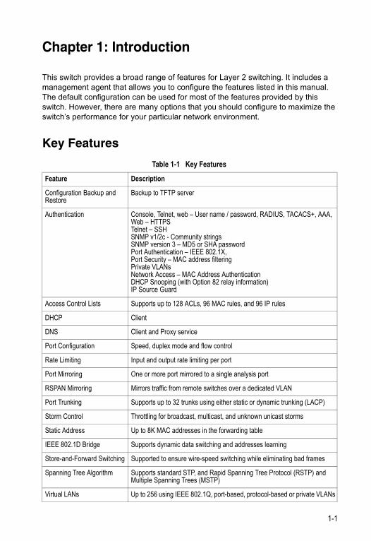
This switch provides a broad range of features for Layer 2 switching. It includes a management agent that allows you to configure the features listed in this manual. The default configuration can be used for most of the features provided by this switch. However, there are many options that you should configure to maximize the switch’s performance for your particular network environment.
Key Features
Table 1-1 Key Features
Feature Description
Configuration Backup and Restore
Backup to TFTP server
Authentication Console, Telnet, web – User name / password, RADIUS, TACACS+, AAA, Web – HTTPSTelnet – SSHSNMP v1/2c - Community stringsSNMP version 3 – MD5 or SHA passwordPort Authentication – IEEE 802.1X, Port Security – MAC address filteringPrivate VLANsNetwork Access – MAC Address AuthenticationDHCP Snooping (with Option 82 relay information)IP Source Guard
Access Control Lists Supports up to 128 ACLs, 96 MAC rules, and 96 IP rules
DHCP Client
DNS Client and Proxy service
Port Configuration Speed, duplex mode and flow control
Rate Limiting Input and output rate limiting per port
Port Mirroring One or more port mirrored to a single analysis port
RSPAN Mirroring Mirrors traffic from remote switches over a dedicated VLAN
Port Trunking Supports up to 32 trunks using either static or dynamic trunking (LACP)
Storm Control Throttling for broadcast, multicast, and unknown unicast storms
Static Address Up to 8K MAC addresses in the forwarding table
IEEE 802.1D Bridge Supports dynamic data switching and addresses learning
Store-and-Forward Switching Supported to ensure wire-speed switching while eliminating bad frames
Spanning Tree Algorithm Supports standard STP, and Rapid Spanning Tree Protocol (RSTP) and Multiple Spanning Trees (MSTP)
Virtual LANs Up to 256 using IEEE 802.1Q, port-based, protocol-based or private VLANs
1-1
Introduction1
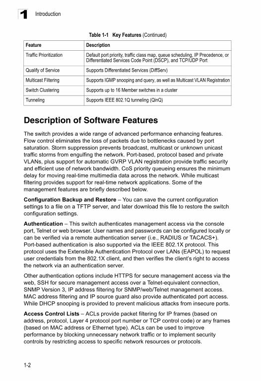
Description of Software FeaturesThe switch provides a wide range of advanced performance enhancing features. Flow control eliminates the loss of packets due to bottlenecks caused by port saturation. Storm suppression prevents broadcast, multicast or unknown unicast traffic storms from engulfing the network. Port-based, protocol based and private VLANs, plus support for automatic GVRP VLAN registration provide traffic security and efficient use of network bandwidth. CoS priority queueing ensures the minimum delay for moving real-time multimedia data across the network. While multicast filtering provides support for real-time network applications. Some of the management features are briefly described below.
Configuration Backup and Restore – You can save the current configuration settings to a file on a TFTP server, and later download this file to restore the switch configuration settings.
Authentication – This switch authenticates management access via the console port, Telnet or web browser. User names and passwords can be configured locally or can be verified via a remote authentication server (i.e., RADIUS or TACACS+). Port-based authentication is also supported via the IEEE 802.1X protocol. This protocol uses the Extensible Authentication Protocol over LANs (EAPOL) to request user credentials from the 802.1X client, and then verifies the client’s right to access the network via an authentication server.
Other authentication options include HTTPS for secure management access via the web, SSH for secure management access over a Telnet-equivalent connection, SNMP Version 3, IP address filtering for SNMP/web/Telnet management access. MAC address filtering and IP source guard also provide authenticated port access. While DHCP snooping is provided to prevent malicious attacks from insecure ports.
Access Control Lists – ACLs provide packet filtering for IP frames (based on address, protocol, Layer 4 protocol port number or TCP control code) or any frames (based on MAC address or Ethernet type). ACLs can be used to improve performance by blocking unnecessary network traffic or to implement security controls by restricting access to specific network resources or protocols.
Traffic Prioritization Default port priority, traffic class map, queue scheduling, IP Precedence, or Differentiated Services Code Point (DSCP), and TCP/UDP Port
Qualify of Service Supports Differentiated Services (DiffServ)
Multicast Filtering Supports IGMP snooping and query, as well as Multicast VLAN Registration
Switch Clustering Supports up to 16 Member switches in a cluster
Tunneling Supports IEEE 802.1Q tunneling (QinQ)
Table 1-1 Key Features (Continued)
Feature Description
1-2
Description of Software Features 1
Port Configuration – You can manually configure the speed, duplex mode, and flow control used on specific ports, or use auto-negotiation to detect the connection settings used by the attached device. Use the full-duplex mode on ports whenever possible to double the throughput of switch connections. Flow control should also be enabled to control network traffic during periods of congestion and prevent the loss of packets when port buffer thresholds are exceeded. The switch supports flow control based on the IEEE 802.3x standard (now incorporated in IEEE 802.3-2002).Rate Limiting – This feature controls the maximum rate for traffic transmitted or received on an interface. Rate limiting is configured on interfaces at the edge of a network to limit traffic into or out of the network. Packets that exceed the acceptable amount of traffic are dropped.
Port Mirroring – The switch can unobtrusively mirror traffic from any port to a monitor port. You can then attach a protocol analyzer or RMON probe to this port to perform traffic analysis and verify connection integrity.
RSPAN Mirroring – You can configure the switch to mirror traffic from remote switches over a dedicated VLAN. The traffic mirrored can be analyzed in the same way you would when mirroring traffic locally on a switch.
Port Trunking – Ports can be combined into an aggregate connection. Trunks can be manually set up or dynamically configured using Link Aggregation Control Protocol (LACP). The additional ports dramatically increase the throughput across any connection, and provide redundancy by taking over the load if a port in the trunk should fail. The switch supports up to 32 trunks.
Storm Control – Broadcast, multicast and unknown unicast storm suppression prevents traffic from overwhelming the network. When enabled on a port, the level of traffic passing through the port is restricted. If traffic rises above a pre-defined threshold, it will be throttled until the level falls back beneath the threshold.
Static Addresses – A static address can be assigned to a specific interface on this switch. Static addresses are bound to the assigned interface and will not be moved. When a static address is seen on another interface, the address will be ignored and will not be written to the address table. Static addresses can be used to provide network security by restricting access for a known host to a specific port.
IP Address Filtering – Access to insecure ports can be controlled using DHCP Snooping which filters ingress traffic based on static IP addresses and addresses stored in the DHCP Snooping table. Traffic can also be restricted to specific source IP addresses or source IP/MAC address pairs based on static entries or entries stored in the DHCP Snooping table.
IEEE 802.1D Bridge – The switch supports IEEE 802.1D transparent bridging. The address table facilitates data switching by learning addresses, and then filtering or forwarding traffic based on this information. The address table supports up to 8K addresses.
Store-and-Forward Switching – The switch copies each frame into its memory before forwarding them to another port. This ensures that all frames are a standard Ethernet size and have been verified for accuracy with the cyclic redundancy check
1-3
Introduction1
(CRC). This prevents bad frames from entering the network and wasting bandwidth.To avoid dropping frames on congested ports, the switch provides 4 Mbits for frame buffering. This buffer can queue packets awaiting transmission on congested networks.
Spanning Tree Algorithm – The switch supports these spanning tree protocols:
Spanning Tree Protocol (STP, IEEE 802.1D) – This protocol provides loop detection and recovery by allowing two or more redundant connections to be created between a pair of LAN segments. When there are multiple physical paths between segments, this protocol will choose a single path and disable all others to ensure that only one route exists between any two stations on the network. This prevents the creation of network loops. However, if the chosen path should fail for any reason, an alternate path will be activated to maintain the connection.
Rapid Spanning Tree Protocol (RSTP, IEEE 802.1D-2004) – This protocol reduces the convergence time for network topology changes to 3 to 5 seconds, compared to 30 seconds or more for the older IEEE 802.1D STP standard. It is intended as a complete replacement for STP, but can still interoperate with switches running the older standard by automatically reconfiguring ports to STP-compliant mode if they detect STP protocol messages from attached devices.
Multiple Spanning Tree Protocol (MSTP, IEEE 802.1D-2004) – This protocol is a direct extension of RSTP. It can provide an independent spanning tree for different VLANs. It simplifies network management, provides for even faster convergence than RSTP by limiting the size of each region, and prevents VLAN members from being segmented from the rest of the group (as sometimes occurs with IEEE 802.1D STP).
Virtual LANs – The switch supports up to 256 VLANs. A Virtual LAN is a collection of network nodes that share the same collision domain regardless of their physical location or connection point in the network. The switch supports tagged VLANs based on the IEEE 802.1Q standard. Members of VLAN groups can be dynamically learned via GVRP, or ports can be manually assigned to a specific set of VLANs. This allows the switch to restrict traffic to the VLAN groups to which a user has been assigned. By segmenting your network into VLANs, you can:
• Eliminate broadcast storms which severely degrade performance in a flat network.• Simplify network management for node changes/moves by remotely configuring
VLAN membership for any port, rather than having to manually change the network connection.
• Provide data security by restricting all traffic to the originating VLAN.• Use private VLANs to restrict traffic to pass only between data ports and the uplink
ports, thereby isolating adjacent ports within the same VLAN, and allowing you to limit the total number of VLANs that need to be configured.
• Use protocol VLANs to restrict traffic to specified interfaces based on protocol type.
Note: The switch allows 255 user-manageable VLANs. One other VLAN (VLAN ID 4093) is reserved for switch clustering.
1-4
Description of Software Features 1
Traffic Prioritization – This switch prioritizes each packet based on the required level of service, using four priority queues with strict or Weighted Round Robin Queuing. It uses IEEE 802.1p and 802.1Q tags to prioritize incoming traffic based on input from the end-station application. These functions can be used to provide independent priorities for delay-sensitive data and best-effort data.This switch also supports several common methods of prioritizing layer 3/4 traffic to meet application requirements. Traffic can be prioritized based on the priority bits in the IP frame’s Type of Service (ToS) octet or the number of the TCP/UDP port. When these services are enabled, the priorities are mapped to a Class of Service value by the switch, and the traffic then sent to the corresponding output queue.
Quality of Service – Differentiated Services (DiffServ) provides policy-based management mechanisms used for prioritizing network resources to meet the requirements of specific traffic types on a per-hop basis. Each packet is classified upon entry into the network based on access lists, IP Precedence or DSCP values, or VLAN lists. Using access lists allows you select traffic based on Layer 2, Layer 3, or Layer 4 information contained in each packet. Based on network policies, different kinds of traffic can be marked for different kinds of forwarding.
Multicast Filtering – Specific multicast traffic can be assigned to its own VLAN to ensure that it does not interfere with normal network traffic and to guarantee real-time delivery by setting the required priority level for the designated VLAN. The switch uses IGMP Snooping and Query to manage multicast group registration. It also supports Multicast VLAN Registration (MVR) which allows common multicast traffic, such as television channels, to be transmitted across a single network-wide multicast VLAN shared by hosts residing in other standard or private VLAN groups, while preserving security and data isolation for normal traffic.
IEEE 802.1Q Tunneling (QinQ) – This feature is designed for service providers carrying traffic for multiple customers across their networks. QinQ tunneling is used to maintain customer-specific VLAN and Layer 2 protocol configurations even when different customers use the same internal VLAN IDs. This is accomplished by inserting Service Provider VLAN (SPVLAN) tags into the customer’s frames when they enter the service provider’s network, and then stripping the tags when the frames leave the network.
1-5
Introduction1
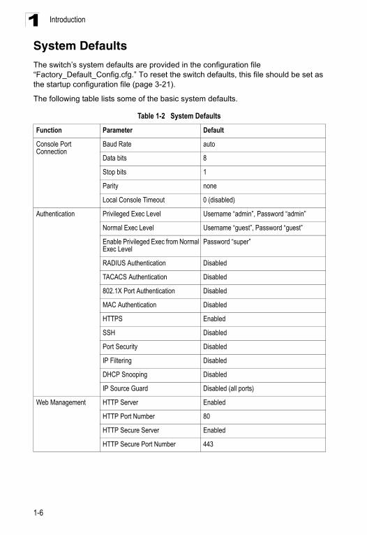
System DefaultsThe switch’s system defaults are provided in the configuration file “Factory_Default_Config.cfg.” To reset the switch defaults, this file should be set as the startup configuration file (page 3-21).The following table lists some of the basic system defaults.
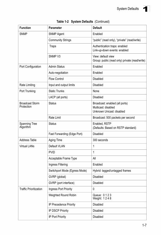
Table 1-2 System Defaults
Function Parameter Default
Console Port Connection
Baud Rate auto
Data bits 8
Stop bits 1
Parity none
Local Console Timeout 0 (disabled)
Authentication Privileged Exec Level Username “admin”, Password “admin”
Normal Exec Level Username “guest”, Password “guest”
Enable Privileged Exec from Normal Exec Level
Password “super”
RADIUS Authentication Disabled
TACACS Authentication Disabled
802.1X Port Authentication Disabled
MAC Authentication Disabled
HTTPS Enabled
SSH Disabled
Port Security Disabled
IP Filtering Disabled
DHCP Snooping Disabled
IP Source Guard Disabled (all ports)
Web Management HTTP Server Enabled
HTTP Port Number 80
HTTP Secure Server Enabled
HTTP Secure Port Number 443
1-6
System Defaults 1
SNMP SNMP Agent Enabled
Community Strings “public” (read only), “private” (read/write)
Traps Authentication traps: enabledLink-up-down events: enabled
SNMP V3 View: default viewGroup: public (read only) private (read/write)
Port Configuration Admin Status Enabled
Auto-negotiation Enabled
Flow Control Disabled
Rate Limiting Input and output limits Disabled
Port Trunking Static Trunks None
LACP (all ports) Disabled
Broadcast Storm Protection
Status Broadcast: enabled (all ports)Multicast: disabledUnknown Unicast: disabled
Rate Limit Broadcast: 500 packets per second
Spanning Tree Algorithm
Status Enabled, RSTP(Defaults: Based on RSTP standard)
Fast Forwarding (Edge Port) Disabled
Address Table Aging Time 300 seconds
Virtual LANs Default VLAN 1
PVID 1
Acceptable Frame Type All
Ingress Filtering Enabled
Switchport Mode (Egress Mode) Hybrid: tagged/untagged frames
GVRP (global) Disabled
GVRP (port interface) Disabled
Traffic Prioritization Ingress Port Priority 0
Weighted Round Robin Queue: 0 1 2 3 Weight: 1 2 4 8
IP Precedence Priority Disabled
IP DSCP Priority Disabled
IP Port Priority Disabled
Table 1-2 System Defaults (Continued)
Function Parameter Default
1-7

Introduction1
IP Settings IP Address DHCP assigned
Subnet Mask 255.255.255.0
Default Gateway 0.0.0.0
DHCP Client: Enabled
DNS Client/Proxy service: Disabled
BOOTP Disabled
Multicast Filtering IGMP Snooping Snooping: EnabledQuerier: Enabled
Multicast VLAN Registration Disabled
System Log Status Enabled
Messages Logged Levels 0-7 (all)
Messages Logged to Flash Levels 0-3
SMTP Email Alerts Event Handler Enabled (but no server defined)
SNTP Clock Synchronization Disabled
DHCP Snooping Status Disabled
IP Source Guard Status Disabled (all ports)
Switch Clustering Status Enabled
Commander Disabled
Table 1-2 System Defaults (Continued)
Function Parameter Default
1-8
Chapter 2: Initial Configuration
Connecting to the Switch
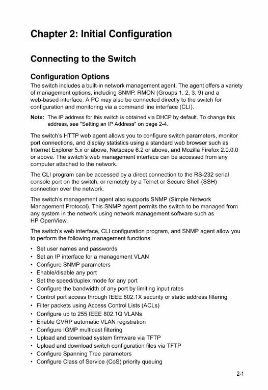
Configuration OptionsThe switch includes a built-in network management agent. The agent offers a variety of management options, including SNMP, RMON (Groups 1, 2, 3, 9) and a web-based interface. A PC may also be connected directly to the switch for configuration and monitoring via a command line interface (CLI).
Note: The IP address for this switch is obtained via DHCP by default. To change this address, see "Setting an IP Address" on page 2-4.
The switch’s HTTP web agent allows you to configure switch parameters, monitor port connections, and display statistics using a standard web browser such as Internet Explorer 5.x or above, Netscape 6.2 or above, and Mozilla Firefox 2.0.0.0 or above. The switch’s web management interface can be accessed from any computer attached to the network.
The CLI program can be accessed by a direct connection to the RS-232 serial console port on the switch, or remotely by a Telnet or Secure Shell (SSH) connection over the network.
The switch’s management agent also supports SNMP (Simple Network Management Protocol). This SNMP agent permits the switch to be managed from any system in the network using network management software such as HP OpenView.
The switch’s web interface, CLI configuration program, and SNMP agent allow you to perform the following management functions:
• Set user names and passwords• Set an IP interface for a management VLAN• Configure SNMP parameters • Enable/disable any port • Set the speed/duplex mode for any port • Configure the bandwidth of any port by limiting input rates
• Control port access through IEEE 802.1X security or static address filtering
• Filter packets using Access Control Lists (ACLs)
• Configure up to 255 IEEE 802.1Q VLANs • Enable GVRP automatic VLAN registration• Configure IGMP multicast filtering• Upload and download system firmware via TFTP• Upload and download switch configuration files via TFTP• Configure Spanning Tree parameters• Configure Class of Service (CoS) priority queuing
2-1
Initial Configuration2
• Configure up to 32 static or LACP trunks• Enable port mirroring• Set broadcast, multicast or unknown unicast storm control on any port• Display system information and statisticsRequired ConnectionsThe switch provides an RS-232 serial port that enables a connection to a PC or terminal for monitoring and configuring the switch. A null-modem console cable is provided with the switch.
Attach a VT100-compatible terminal, or a PC running a terminal emulation program to the switch. You can use the console cable provided with this package, or use a null-modem cable that complies with the wiring assignments shown in the Installation Guide.
To connect a terminal to the console port, complete the following steps:
1. Connect the console cable to the serial port on a terminal, or a PC running terminal emulation software, and tighten the captive retaining screws on the RS-232 connector.
2. Connect the other end of the cable to the RS-232 serial port on the switch.
3. Make sure the terminal emulation software is set as follows:
• Select the appropriate serial port (COM port 1 or COM port 2). • Set to any of the following baud rates: 9600, 19200, 38400, 57600, 115200
(Note: Set to 9600 baud if want to view all the system initialization messages.).• Set the data format to 8 data bits, 1 stop bit, and no parity. • Set flow control to none. • Set the emulation mode to VT100. • When using HyperTerminal, select Terminal keys, not Windows keys.
Notes: 1. Refer to "Line Commands" on page 4-31 for a complete description of console configuration options.
2. Once you have set up the terminal correctly, the console login screen will be displayed.
For a description of how to use the CLI, see "Using the Command Line Interface" on page 4-1. For a list of all the CLI commands and detailed information on using the CLI, refer to "Command Groups" on page 4-10.
2-2
Basic Configuration 2
Remote ConnectionsPrior to accessing the switch’s onboard agent via a network connection, you must first configure it with a valid IP address, subnet mask, and default gateway using a console connection, DHCP or BOOTP protocol.The IP address for this switch is obtained via DHCP by default. To manually configure this address or enable dynamic address assignment via DHCP or BOOTP, see "Setting an IP Address" on page 2-4.
Note: This switch supports four concurrent Telnet/SSH sessions.
After configuring the switch’s IP parameters, you can access the onboard configuration program from anywhere within the attached network. The switch’s command-line interface can be accessed using Telnet or SSH from any computer attached to the network. The switch can also be managed by any computer using a web browser (Internet Explorer 5.x or above, or Netscape 6.2 or above, or Mozilla Firefox 2.0.0.0), or from a network computer using SNMP network management software.
Note: The onboard program only provides access to basic configuration functions. To access the full range of SNMP management functions, you must use SNMP-based network management software.
Basic Configuration
Console ConnectionThe CLI program provides two different command levels — normal access level (Normal Exec) and privileged access level (Privileged Exec). The commands available at the Normal Exec level are a limited subset of those available at the Privileged Exec level and allow you to only display information and use basic utilities. To fully configure the switch parameters, you must access the CLI at the Privileged Exec level.
Access to both CLI levels are controlled by user names and passwords. The switch has a default user name and password for each level. To log into the CLI at the Privileged Exec level using the default user name and password, perform these steps:
1. To initiate your console connection, press <Enter>. The “User Access Verification” procedure starts.
2. At the Username prompt, enter “admin.”
3. At the Password prompt, also enter “admin.” (The password characters are not displayed on the console screen.)
4. The session is opened and the CLI displays the “Console#” prompt indicating you have access at the Privileged Exec level.
2-3
Initial Configuration2
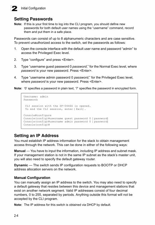
Setting PasswordsNote: If this is your first time to log into the CLI program, you should define newpasswords for both default user names using the “username” command, record them and put them in a safe place.
Passwords can consist of up to 8 alphanumeric characters and are case sensitive. To prevent unauthorized access to the switch, set the passwords as follows:
1. Open the console interface with the default user name and password “admin” to access the Privileged Exec level.
2. Type “configure” and press <Enter>.
3. Type “username guest password 0 password,” for the Normal Exec level, where password is your new password. Press <Enter>.
4. Type “username admin password 0 password,” for the Privileged Exec level, where password is your new password. Press <Enter>.
Note: ‘0’ specifies a password in plain text, ‘7’ specifies the password in encrypted form.
Setting an IP AddressYou must establish IP address information for the stack to obtain management access through the network. This can be done in either of the following ways:
Manual — You have to input the information, including IP address and subnet mask. If your management station is not in the same IP subnet as the stack’s master unit, you will also need to specify the default gateway router.
Dynamic — The switch sends IP configuration requests to BOOTP or DHCP address allocation servers on the network.
Manual ConfigurationYou can manually assign an IP address to the switch. You may also need to specify a default gateway that resides between this device and management stations that exist on another network segment. Valid IP addresses consist of four decimal numbers, 0 to 255, separated by periods. Anything outside this format will not be accepted by the CLI program.
Note: The IP address for this switch is obtained via DHCP by default.
Username: adminPassword:
CLI session with the SF-0446G is opened. To end the CLI session, enter [Exit].
Console#configureConsole(config)#username guest password 0 [password]Console(config)#username admin password 0 [password]Console(config)#
2-4
Basic Configuration 2
Before you can assign an IP address to the switch, you must obtain the following information from your network administrator:• IP address for the switch • Default gateway for the network • Network mask for this network
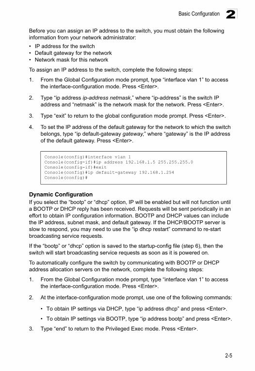
To assign an IP address to the switch, complete the following steps:
1. From the Global Configuration mode prompt, type “interface vlan 1” to access the interface-configuration mode. Press <Enter>.
2. Type “ip address ip-address netmask,” where “ip-address” is the switch IP address and “netmask” is the network mask for the network. Press <Enter>.
3. Type “exit” to return to the global configuration mode prompt. Press <Enter>.
4. To set the IP address of the default gateway for the network to which the switch belongs, type “ip default-gateway gateway,” where “gateway” is the IP address of the default gateway. Press <Enter>.
Dynamic ConfigurationIf you select the “bootp” or “dhcp” option, IP will be enabled but will not function until a BOOTP or DHCP reply has been received. Requests will be sent periodically in an effort to obtain IP configuration information. BOOTP and DHCP values can include the IP address, subnet mask, and default gateway. If the DHCP/BOOTP server is slow to respond, you may need to use the “ip dhcp restart” command to re-start broadcasting service requests.
If the “bootp” or “dhcp” option is saved to the startup-config file (step 6), then the switch will start broadcasting service requests as soon as it is powered on.
To automatically configure the switch by communicating with BOOTP or DHCP address allocation servers on the network, complete the following steps:
1. From the Global Configuration mode prompt, type “interface vlan 1” to access the interface-configuration mode. Press <Enter>.
2. At the interface-configuration mode prompt, use one of the following commands:
• To obtain IP settings via DHCP, type “ip address dhcp” and press <Enter>.
• To obtain IP settings via BOOTP, type “ip address bootp” and press <Enter>.
3. Type “end” to return to the Privileged Exec mode. Press <Enter>.
Console(config)#interface vlan 1Console(config-if)#ip address 192.168.1.5 255.255.255.0Console(config-if)#exitConsole(config)#ip default-gateway 192.168.1.254Console(config)#
2-5
Initial Configuration2
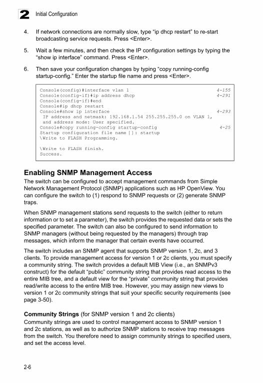
4. If network connections are normally slow, type “ip dhcp restart” to re-startbroadcasting service requests. Press <Enter>.
5. Wait a few minutes, and then check the IP configuration settings by typing the “show ip interface” command. Press <Enter>.
6. Then save your configuration changes by typing “copy running-config startup-config.” Enter the startup file name and press <Enter>.
Enabling SNMP Management Access The switch can be configured to accept management commands from Simple Network Management Protocol (SNMP) applications such as HP OpenView. You can configure the switch to (1) respond to SNMP requests or (2) generate SNMP traps.
When SNMP management stations send requests to the switch (either to return information or to set a parameter), the switch provides the requested data or sets the specified parameter. The switch can also be configured to send information to SNMP managers (without being requested by the managers) through trap messages, which inform the manager that certain events have occurred.
The switch includes an SNMP agent that supports SNMP version 1, 2c, and 3 clients. To provide management access for version 1 or 2c clients, you must specify a community string. The switch provides a default MIB View (i.e., an SNMPv3 construct) for the default “public” community string that provides read access to the entire MIB tree, and a default view for the “private” community string that provides read/write access to the entire MIB tree. However, you may assign new views to version 1 or 2c community strings that suit your specific security requirements (see page 3-50).
Community Strings (for SNMP version 1 and 2c clients)Community strings are used to control management access to SNMP version 1 and 2c stations, as well as to authorize SNMP stations to receive trap messages from the switch. You therefore need to assign community strings to specified users, and set the access level.
Console(config)#interface vlan 1 4-155Console(config-if)#ip address dhcp 4-291Console(config-if)#endConsole#ip dhcp restart Console#show ip interface 4-293 IP address and netmask: 192.168.1.54 255.255.255.0 on VLAN 1, and address mode: User specified.Console#copy running-config startup-config 4-25Startup configuration file name []: startup\Write to FLASH Programming.
\Write to FLASH finish.Success.
2-6
Basic Configuration 2
The default strings are:• public - with read-only access. Authorized management stations are only able to retrieve MIB objects.
• private - with read-write access. Authorized management stations are able to both retrieve and modify MIB objects.
To prevent unauthorized access to the switch from SNMP version 1 or 2c clients, it is recommended that you change the default community strings.
To configure a community string, complete the following steps:
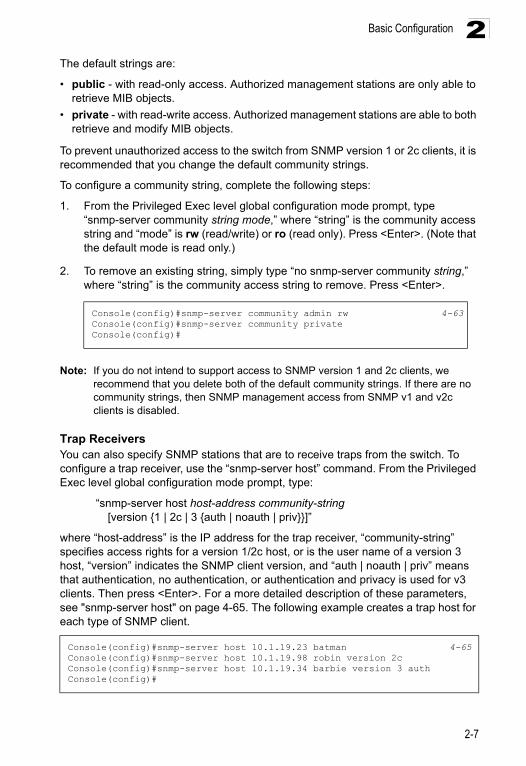
1. From the Privileged Exec level global configuration mode prompt, type “snmp-server community string mode,” where “string” is the community access string and “mode” is rw (read/write) or ro (read only). Press <Enter>. (Note that the default mode is read only.)
2. To remove an existing string, simply type “no snmp-server community string,” where “string” is the community access string to remove. Press <Enter>.
Note: If you do not intend to support access to SNMP version 1 and 2c clients, we recommend that you delete both of the default community strings. If there are no community strings, then SNMP management access from SNMP v1 and v2c clients is disabled.
Trap ReceiversYou can also specify SNMP stations that are to receive traps from the switch. To configure a trap receiver, use the “snmp-server host” command. From the Privileged Exec level global configuration mode prompt, type:
“snmp-server host host-address community-string [version {1 | 2c | 3 {auth | noauth | priv}}]”
where “host-address” is the IP address for the trap receiver, “community-string” specifies access rights for a version 1/2c host, or is the user name of a version 3 host, “version” indicates the SNMP client version, and “auth | noauth | priv” means that authentication, no authentication, or authentication and privacy is used for v3 clients. Then press <Enter>. For a more detailed description of these parameters, see "snmp-server host" on page 4-65. The following example creates a trap host for each type of SNMP client.
Console(config)#snmp-server community admin rw 4-63Console(config)#snmp-server community privateConsole(config)#
Console(config)#snmp-server host 10.1.19.23 batman 4-65Console(config)#snmp-server host 10.1.19.98 robin version 2cConsole(config)#snmp-server host 10.1.19.34 barbie version 3 authConsole(config)#
2-7
Initial Configuration2
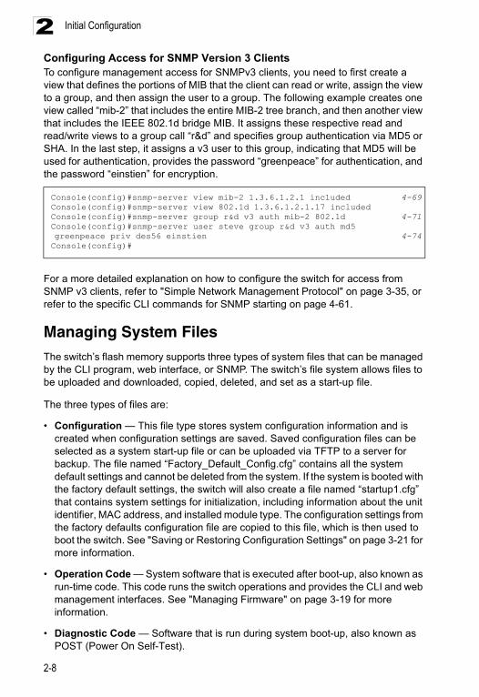
Configuring Access for SNMP Version 3 ClientsTo configure management access for SNMPv3 clients, you need to first create a view that defines the portions of MIB that the client can read or write, assign the view to a group, and then assign the user to a group. The following example creates one view called “mib-2” that includes the entire MIB-2 tree branch, and then another view that includes the IEEE 802.1d bridge MIB. It assigns these respective read and read/write views to a group call “r&d” and specifies group authentication via MD5 or SHA. In the last step, it assigns a v3 user to this group, indicating that MD5 will be used for authentication, provides the password “greenpeace” for authentication, and the password “einstien” for encryption.For a more detailed explanation on how to configure the switch for access from SNMP v3 clients, refer to "Simple Network Management Protocol" on page 3-35, or refer to the specific CLI commands for SNMP starting on page 4-61.
Managing System FilesThe switch’s flash memory supports three types of system files that can be managed by the CLI program, web interface, or SNMP. The switch’s file system allows files to be uploaded and downloaded, copied, deleted, and set as a start-up file.
The three types of files are:
• Configuration — This file type stores system configuration information and is created when configuration settings are saved. Saved configuration files can be selected as a system start-up file or can be uploaded via TFTP to a server for backup. The file named “Factory_Default_Config.cfg” contains all the system default settings and cannot be deleted from the system. If the system is booted with the factory default settings, the switch will also create a file named “startup1.cfg” that contains system settings for initialization, including information about the unit identifier, MAC address, and installed module type. The configuration settings from the factory defaults configuration file are copied to this file, which is then used to boot the switch. See "Saving or Restoring Configuration Settings" on page 3-21 for more information.
• Operation Code — System software that is executed after boot-up, also known as run-time code. This code runs the switch operations and provides the CLI and web management interfaces. See "Managing Firmware" on page 3-19 for more information.
• Diagnostic Code — Software that is run during system boot-up, also known as POST (Power On Self-Test).
Console(config)#snmp-server view mib-2 1.3.6.1.2.1 included 4-69Console(config)#snmp-server view 802.1d 1.3.6.1.2.1.17 includedConsole(config)#snmp-server group r&d v3 auth mib-2 802.1d 4-71Console(config)#snmp-server user steve group r&d v3 auth md5 greenpeace priv des56 einstien 4-74Console(config)#
2-8
Managing System Files 2
Due to the size limit of the flash memory, the switch supports only two operation code files. However, you can have as many diagnostic code files and configuration files as available flash memory space allows. The switch has a total of 16 Mbytes of flash memory for system files.In the system flash memory, one file of each type must be set as the start-up file. During a system boot, the diagnostic and operation code files set as the start-up file are run, and then the start-up configuration file is loaded.
Note that configuration files should be downloaded using a file name that reflects the contents or usage of the file settings. If you download directly to the running-config, the system will reboot, and the settings will have to be copied from the running-config to a permanent file.
Saving Configuration SettingsConfiguration commands only modify the running configuration file and are not saved when the switch is rebooted. To save all your configuration changes in nonvolatile storage, you must copy the running configuration file to the start-up configuration file using the “copy” command.
New startup configuration files must have a name specified. File names on the switch are case-sensitive, can be from 1 to 31 characters, must not contain slashes (\ or /), and the leading letter of the file name must not be a period (.). (Valid characters: A-Z, a-z, 0-9, “.”, “-”, “_”)
There can be more than one user-defined configuration file saved in the switch’s flash memory, but only one is designated as the “startup” file that is loaded when the switch boots. The copy running-config startup-config command always sets the new file as the startup file. To select a previously saved configuration file, use the boot system config:<filename> command.
The maximum number of saved configuration files depends on available flash memory, with each configuration file normally requiring less than 20 kbytes. The amount of available flash memory can be checked by using the dir command.
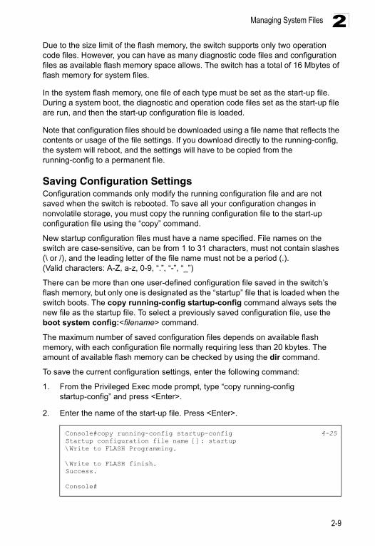
To save the current configuration settings, enter the following command:
1. From the Privileged Exec mode prompt, type “copy running-config startup-config” and press <Enter>.
2. Enter the name of the start-up file. Press <Enter>.
Console#copy running-config startup-config 4-25Startup configuration file name []: startup\Write to FLASH Programming.
\Write to FLASH finish.Success.
Console#
2-9

Initial Configuration2
2-10
Chapter 3: Configuring the Switch
Using the Web InterfaceThis switch provides an embedded HTTP web agent. Using a web browser you can configure the switch and view statistics to monitor network activity. The web agent can be accessed by any computer on the network using a standard web browser (Internet Explorer 5.0 or above, Netscape 6.2 or above, or Mozilla Firefox 2.0.0.0 or above).
Note: You can also use the Command Line Interface (CLI) to manage the switch over a serial connection to the console port or via Telnet. For more information on using the CLI, refer to “Chapter 4: Command Line Interface.”
Prior to accessing the switch from a web browser, be sure you have first performed the following tasks:
1. Configure the switch with a valid IP address, subnet mask, and default gateway using an out-of-band serial connection, BOOTP or DHCP protocol. (See "Setting an IP Address" on page 2-4.)
2. Set user names and passwords using an out-of-band serial connection. Access to the web agent is controlled by the same user names and passwords as the onboard configuration program. (See "Setting Passwords" on page 2-4.)
3. After you enter a user name and password, you will have access to the system configuration program.
Notes: 1. You are allowed three attempts to enter the correct password; on the third failed attempt the current connection is terminated.
2. If you log into the web interface as guest (Normal Exec level), you can view the configuration settings or change the guest password. If you log in as “admin” (Privileged Exec level), you can change the settings on any page.
3. If the path between your management station and this switch does not pass through any device that uses the Spanning Tree Algorithm, then you can set the switch port attached to your management station to fast forwarding (i.e., enable Admin Edge Port) to improve the switch’s response time to management commands issued through the web interface. See "Configuring Interface Settings for STA" on page 3-134.
3-1
Configuring the Switch3
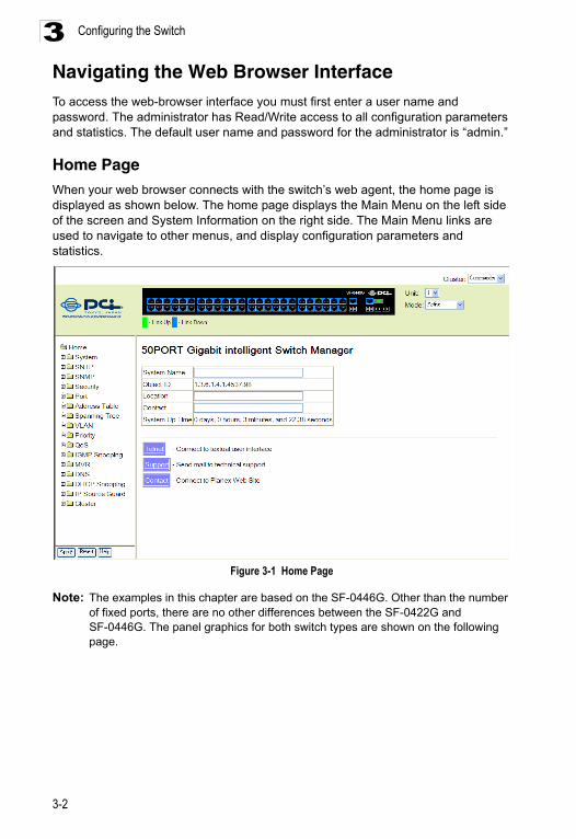
Navigating the Web Browser InterfaceTo access the web-browser interface you must first enter a user name and password. The administrator has Read/Write access to all configuration parameters and statistics. The default user name and password for the administrator is “admin.”Home PageWhen your web browser connects with the switch’s web agent, the home page is displayed as shown below. The home page displays the Main Menu on the left side of the screen and System Information on the right side. The Main Menu links are used to navigate to other menus, and display configuration parameters and statistics.
Figure 3-1 Home Page
Note: The examples in this chapter are based on the SF-0446G. Other than the number of fixed ports, there are no other differences between the SF-0422G and SF-0446G. The panel graphics for both switch types are shown on the following page.
3-2
Navigating the Web Browser Interface 3
Configuration OptionsConfigurable parameters have a dialog box or a drop-down list. Once a configuration change has been made on a page, be sure to click on the Apply button to confirm the new setting. The following table summarizes the web page configuration buttons.Notes: 1. To ensure proper screen refresh, be sure that Internet Explorer is configured so that the setting “Check for newer versions of stored pages” reads “Every visit to the page”.Internet Explorer 6.x and earlier: This option is available under the menu “Tools / Internet Options / General / Temporary Internet Files / Settings”.Internet Explorer 7.x: This option is available under “Tools / Internet Options / General / Browsing History / Settings / Temporary Internet Files”.
2. When using Internet Explorer 5.0, you may have to manually refresh the screen after making configuration changes by pressing the browser’s refresh button.
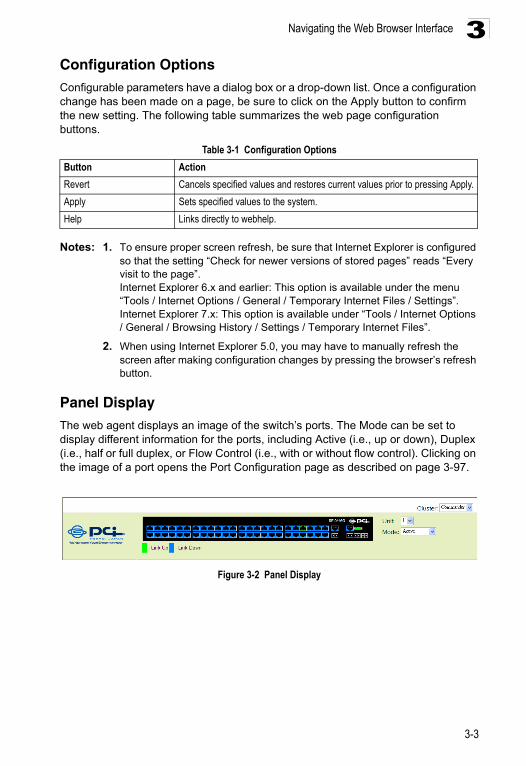
Panel DisplayThe web agent displays an image of the switch’s ports. The Mode can be set to display different information for the ports, including Active (i.e., up or down), Duplex (i.e., half or full duplex, or Flow Control (i.e., with or without flow control). Clicking on the image of a port opens the Port Configuration page as described on page 3-97.
Figure 3-2 Panel Display
Table 3-1 Configuration Options
Button Action
Revert Cancels specified values and restores current values prior to pressing Apply.
Apply Sets specified values to the system.
Help Links directly to webhelp.
3-3
Configuring the Switch3
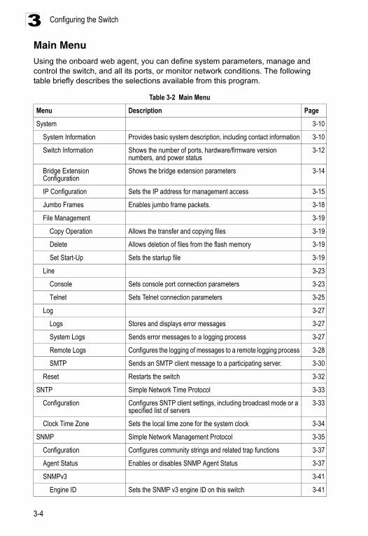
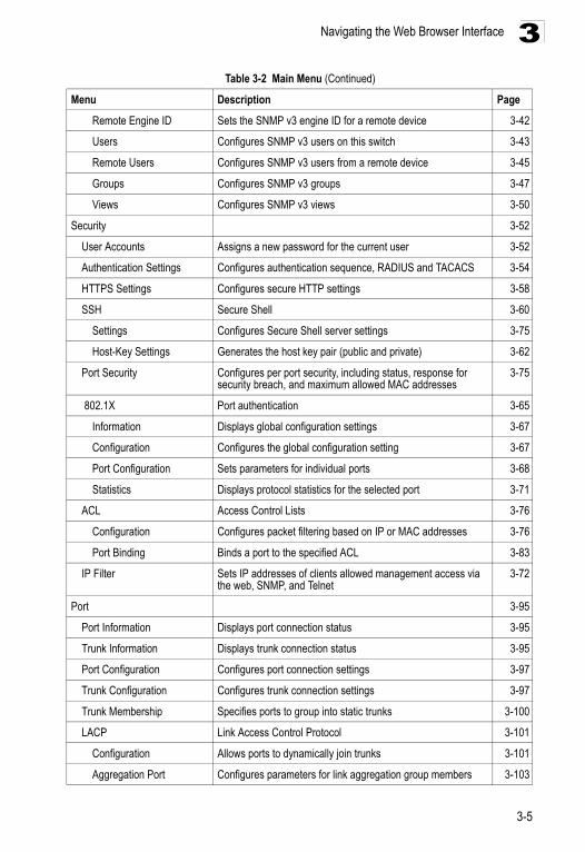
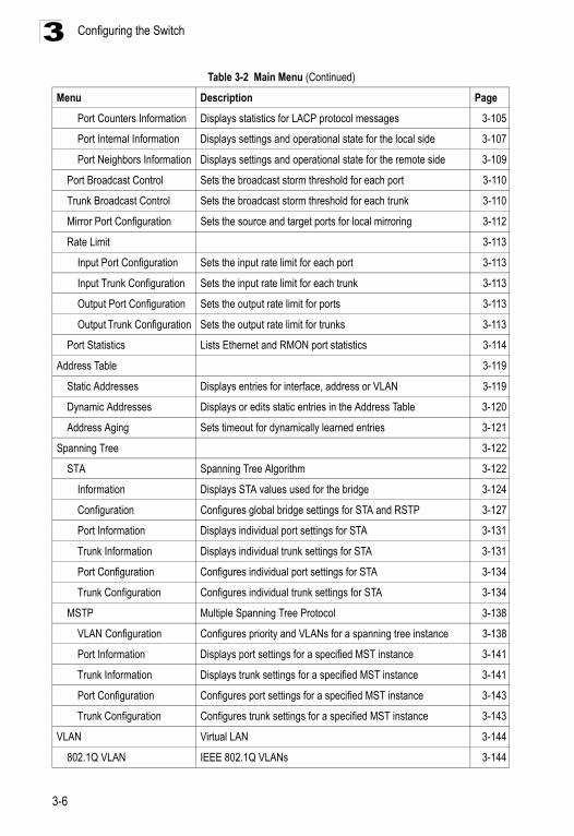
Main Menu Using the onboard web agent, you can define system parameters, manage and control the switch, and all its ports, or monitor network conditions. The following table briefly describes the selections available from this program.Table 3-2 Main Menu
Menu Description Page
System 3-10
System Information Provides basic system description, including contact information 3-10
Switch Information Shows the number of ports, hardware/firmware version numbers, and power status
3-12
Bridge Extension Configuration
Shows the bridge extension parameters 3-14
IP Configuration Sets the IP address for management access 3-15
Jumbo Frames Enables jumbo frame packets. 3-18
File Management 3-19
Copy Operation Allows the transfer and copying files 3-19
Delete Allows deletion of files from the flash memory 3-19
Set Start-Up Sets the startup file 3-19
Line 3-23
Console Sets console port connection parameters 3-23
Telnet Sets Telnet connection parameters 3-25
Log 3-27
Logs Stores and displays error messages 3-27
System Logs Sends error messages to a logging process 3-27
Remote Logs Configures the logging of messages to a remote logging process 3-28
SMTP Sends an SMTP client message to a participating server. 3-30
Reset Restarts the switch 3-32
SNTP Simple Network Time Protocol 3-33
Configuration Configures SNTP client settings, including broadcast mode or a specified list of servers
3-33
Clock Time Zone Sets the local time zone for the system clock 3-34
SNMP Simple Network Management Protocol 3-35
Configuration Configures community strings and related trap functions 3-37
Agent Status Enables or disables SNMP Agent Status 3-37
SNMPv3 3-41
Engine ID Sets the SNMP v3 engine ID on this switch 3-41
3-4
Navigating the Web Browser Interface 3
Remote Engine ID Sets the SNMP v3 engine ID for a remote device 3-42
Users Configures SNMP v3 users on this switch 3-43
Remote Users Configures SNMP v3 users from a remote device 3-45
Groups Configures SNMP v3 groups 3-47
Views Configures SNMP v3 views 3-50
Security 3-52
User Accounts Assigns a new password for the current user 3-52
Authentication Settings Configures authentication sequence, RADIUS and TACACS 3-54
HTTPS Settings Configures secure HTTP settings 3-58
SSH Secure Shell 3-60
Settings Configures Secure Shell server settings 3-75
Host-Key Settings Generates the host key pair (public and private) 3-62
Port Security Configures per port security, including status, response for security breach, and maximum allowed MAC addresses
3-75
802.1X Port authentication 3-65
Information Displays global configuration settings 3-67
Configuration Configures the global configuration setting 3-67
Port Configuration Sets parameters for individual ports 3-68
Statistics Displays protocol statistics for the selected port 3-71
ACL Access Control Lists 3-76
Configuration Configures packet filtering based on IP or MAC addresses 3-76
Port Binding Binds a port to the specified ACL 3-83
IP Filter Sets IP addresses of clients allowed management access via the web, SNMP, and Telnet
3-72
Port 3-95
Port Information Displays port connection status 3-95
Trunk Information Displays trunk connection status 3-95
Port Configuration Configures port connection settings 3-97
Trunk Configuration Configures trunk connection settings 3-97
Trunk Membership Specifies ports to group into static trunks 3-100
LACP Link Access Control Protocol 3-101
Configuration Allows ports to dynamically join trunks 3-101
Aggregation Port Configures parameters for link aggregation group members 3-103
Table 3-2 Main Menu (Continued)
Menu Description Page
3-5
Configuring the Switch3
Port Counters Information Displays statistics for LACP protocol messages 3-105
Port Internal Information Displays settings and operational state for the local side 3-107
Port Neighbors Information Displays settings and operational state for the remote side 3-109
Port Broadcast Control Sets the broadcast storm threshold for each port 3-110
Trunk Broadcast Control Sets the broadcast storm threshold for each trunk 3-110
Mirror Port Configuration Sets the source and target ports for local mirroring 3-112
Rate Limit 3-113
Input Port Configuration Sets the input rate limit for each port 3-113
Input Trunk Configuration Sets the input rate limit for each trunk 3-113
Output Port Configuration Sets the output rate limit for ports 3-113
Output Trunk Configuration Sets the output rate limit for trunks 3-113
Port Statistics Lists Ethernet and RMON port statistics 3-114
Address Table 3-119
Static Addresses Displays entries for interface, address or VLAN 3-119
Dynamic Addresses Displays or edits static entries in the Address Table 3-120
Address Aging Sets timeout for dynamically learned entries 3-121
Spanning Tree 3-122
STA Spanning Tree Algorithm 3-122
Information Displays STA values used for the bridge 3-124
Configuration Configures global bridge settings for STA and RSTP 3-127
Port Information Displays individual port settings for STA 3-131
Trunk Information Displays individual trunk settings for STA 3-131
Port Configuration Configures individual port settings for STA 3-134
Trunk Configuration Configures individual trunk settings for STA 3-134
MSTP Multiple Spanning Tree Protocol 3-138
VLAN Configuration Configures priority and VLANs for a spanning tree instance 3-138
Port Information Displays port settings for a specified MST instance 3-141
Trunk Information Displays trunk settings for a specified MST instance 3-141
Port Configuration Configures port settings for a specified MST instance 3-143
Trunk Configuration Configures trunk settings for a specified MST instance 3-143
VLAN Virtual LAN 3-144
802.1Q VLAN IEEE 802.1Q VLANs 3-144
Table 3-2 Main Menu (Continued)
Menu Description Page
3-6
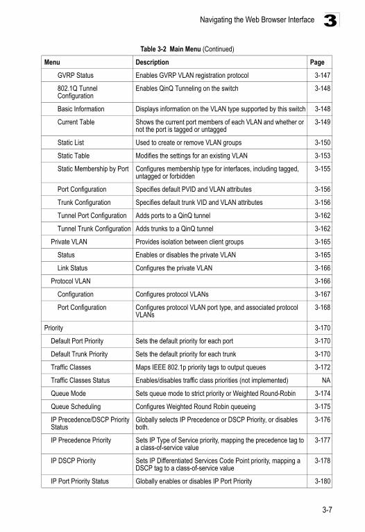
Navigating the Web Browser Interface 3
GVRP Status Enables GVRP VLAN registration protocol 3-147
802.1Q Tunnel Configuration
Enables QinQ Tunneling on the switch 3-148
Basic Information Displays information on the VLAN type supported by this switch 3-148
Current Table Shows the current port members of each VLAN and whether or not the port is tagged or untagged
3-149
Static List Used to create or remove VLAN groups 3-150
Static Table Modifies the settings for an existing VLAN 3-153
Static Membership by Port Configures membership type for interfaces, including tagged, untagged or forbidden
3-155
Port Configuration Specifies default PVID and VLAN attributes 3-156
Trunk Configuration Specifies default trunk VID and VLAN attributes 3-156
Tunnel Port Configuration Adds ports to a QinQ tunnel 3-162
Tunnel Trunk Configuration Adds trunks to a QinQ tunnel 3-162
Private VLAN Provides isolation between client groups 3-165
Status Enables or disables the private VLAN 3-165
Link Status Configures the private VLAN 3-166
Protocol VLAN 3-166
Configuration Configures protocol VLANs 3-167
Port Configuration Configures protocol VLAN port type, and associated protocol VLANs
3-168
Priority 3-170
Default Port Priority Sets the default priority for each port 3-170
Default Trunk Priority Sets the default priority for each trunk 3-170
Traffic Classes Maps IEEE 802.1p priority tags to output queues 3-172
Traffic Classes Status Enables/disables traffic class priorities (not implemented) NA
Queue Mode Sets queue mode to strict priority or Weighted Round-Robin 3-174
Queue Scheduling Configures Weighted Round Robin queueing 3-175
IP Precedence/DSCP Priority Status
Globally selects IP Precedence or DSCP Priority, or disables both.
3-176
IP Precedence Priority Sets IP Type of Service priority, mapping the precedence tag to a class-of-service value
3-177
IP DSCP Priority Sets IP Differentiated Services Code Point priority, mapping a DSCP tag to a class-of-service value
3-178
IP Port Priority Status Globally enables or disables IP Port Priority 3-180
Table 3-2 Main Menu (Continued)
Menu Description Page
3-7
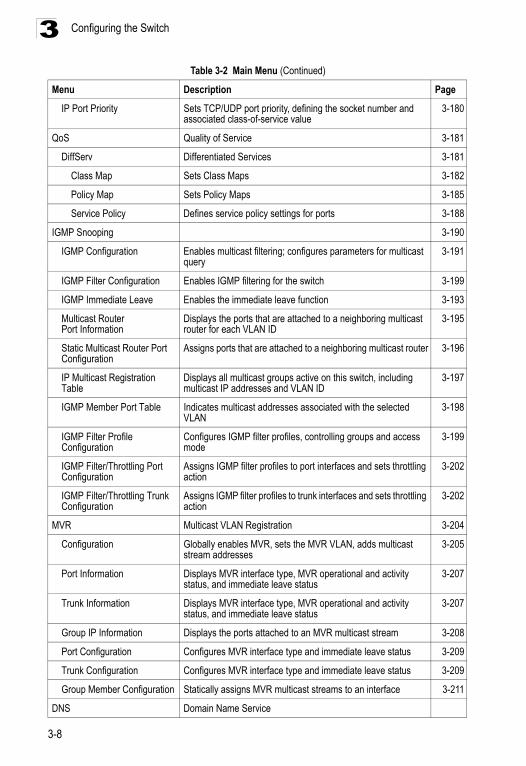
Configuring the Switch3
IP Port Priority Sets TCP/UDP port priority, defining the socket number and associated class-of-service value
3-180
QoS Quality of Service 3-181
DiffServ Differentiated Services 3-181
Class Map Sets Class Maps 3-182
Policy Map Sets Policy Maps 3-185
Service Policy Defines service policy settings for ports 3-188
IGMP Snooping 3-190
IGMP Configuration Enables multicast filtering; configures parameters for multicast query
3-191
IGMP Filter Configuration Enables IGMP filtering for the switch 3-199
IGMP Immediate Leave Enables the immediate leave function 3-193
Multicast Router Port Information
Displays the ports that are attached to a neighboring multicast router for each VLAN ID
3-195
Static Multicast Router Port Configuration
Assigns ports that are attached to a neighboring multicast router 3-196
IP Multicast Registration Table
Displays all multicast groups active on this switch, including multicast IP addresses and VLAN ID
3-197
IGMP Member Port Table Indicates multicast addresses associated with the selected VLAN
3-198
IGMP Filter Profile Configuration
Configures IGMP filter profiles, controlling groups and access mode
3-199
IGMP Filter/Throttling Port Configuration
Assigns IGMP filter profiles to port interfaces and sets throttling action
3-202
IGMP Filter/Throttling Trunk Configuration
Assigns IGMP filter profiles to trunk interfaces and sets throttling action
3-202
MVR Multicast VLAN Registration 3-204
Configuration Globally enables MVR, sets the MVR VLAN, adds multicast stream addresses
3-205
Port Information Displays MVR interface type, MVR operational and activity status, and immediate leave status
3-207
Trunk Information Displays MVR interface type, MVR operational and activity status, and immediate leave status
3-207
Group IP Information Displays the ports attached to an MVR multicast stream 3-208
Port Configuration Configures MVR interface type and immediate leave status 3-209
Trunk Configuration Configures MVR interface type and immediate leave status 3-209
Group Member Configuration Statically assigns MVR multicast streams to an interface 3-211
DNS Domain Name Service
Table 3-2 Main Menu (Continued)
Menu Description Page
3-8
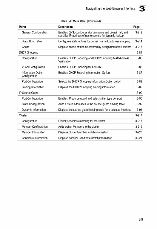
Navigating the Web Browser Interface 3
General Configuration Enables DNS; configures domain name and domain list; and specifies IP address of name servers for dynamic lookup
3-212
Static Host Table Configures static entries for domain name to address mapping 3-214
Cache Displays cache entries discovered by designated name servers 3-216
DHCP Snooping 3-84
Configuration Enables DHCP Snooping and DHCP Snooping MAC-Address Verification
3-85
VLAN Configuration Enables DHCP Snooping for a VLAN 3-86
Information Option Configuration
Enables DHCP Snooping Information Option 3-87
Port Configuration Selects the DHCP Snooping Information Option policy 3-88
Binding Information Displays the DHCP Snooping binding information 3-89
IP Source Guard 3-90
Port Configuration Enables IP source guard and selects filter type per port 3-90
Static Configuration Adds a static addresses to the source-guard binding table 3-92
Dynamic Information Displays the source-guard binding table for a selected interface 3-94
Cluster 3-217
Configuration Globally enables clustering for the switch 3-217
Member Configuration Adds switch Members to the cluster 3-219
Member Information Displays cluster Member switch information 3-220
Candidate Information Displays network Candidate switch information 3-221
Table 3-2 Main Menu (Continued)
Menu Description Page
3-9
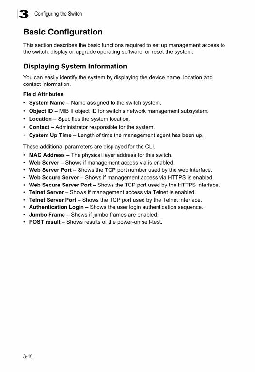
Configuring the Switch3
Basic ConfigurationThis section describes the basic functions required to set up management access to the switch, display or upgrade operating software, or reset the system.Displaying System InformationYou can easily identify the system by displaying the device name, location and contact information.
Field Attributes
• System Name – Name assigned to the switch system.
• Object ID – MIB II object ID for switch’s network management subsystem.
• Location – Specifies the system location.
• Contact – Administrator responsible for the system.
• System Up Time – Length of time the management agent has been up.
These additional parameters are displayed for the CLI.
• MAC Address – The physical layer address for this switch. • Web Server – Shows if management access via is enabled.• Web Server Port – Shows the TCP port number used by the web interface.• Web Secure Server – Shows if management access via HTTPS is enabled.• Web Secure Server Port – Shows the TCP port used by the HTTPS interface.• Telnet Server – Shows if management access via Telnet is enabled.• Telnet Server Port – Shows the TCP port used by the Telnet interface.• Authentication Login – Shows the user login authentication sequence.• Jumbo Frame – Shows if jumbo frames are enabled.• POST result – Shows results of the power-on self-test.
3-10
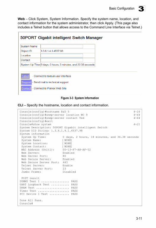
Basic Configuration 3
Web – Click System, System Information. Specify the system name, location, and contact information for the system administrator, then click Apply. (This page also includes a Telnet button that allows access to the Command Line Interface via Telnet.)Figure 3-3 System Information
CLI – Specify the hostname, location and contact information.
Console(config)#hostname R&D 5 4-16Console(config)#snmp-server location WC 9 4-64Console(config)#snmp-server contact Ted 4-64Console(config)#exitConsole#show system 4-21System Description: 50PORT Gigabit intelligent SwitchSystem OID String: 1.3.6.1.4.1.4537.98System information System Up Time: 0 days, 2 hours, 18 minutes, and 36.38 seconds System Name: [NONE] System Location: [NONE] System Contact: [NONE] MAC Address (Unit1): 00-13-F7-A8-AF-52 Web Server: Enabled Web Server Port: 80 Web Secure Server: Enabled Web Secure Server Port: 443 Telnet Server: Enable Telnet Server Port: 23 Jumbo Frame: Disabled
POST resultDUMMY Test 1 ................. PASSUART Loopback Test ........... PASSDRAM Test .................... PASSTimer Test ................... PASSPCI Device 1 Test ............ PASS
Done All Pass.Console#
3-11
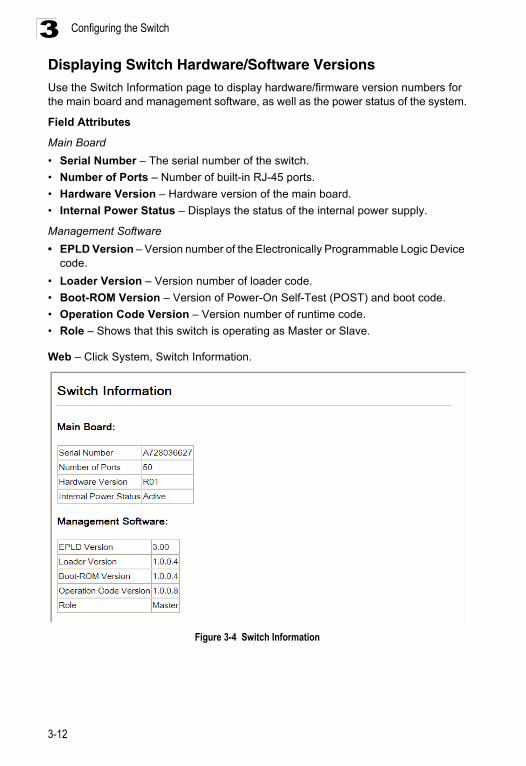
Configuring the Switch3
Displaying Switch Hardware/Software Versions Use the Switch Information page to display hardware/firmware version numbers for the main board and management software, as well as the power status of the system.Field Attributes
Main Board
• Serial Number – The serial number of the switch.
• Number of Ports – Number of built-in RJ-45 ports.
• Hardware Version – Hardware version of the main board.
• Internal Power Status – Displays the status of the internal power supply.
Management Software
• EPLD Version – Version number of the Electronically Programmable Logic Device code.
• Loader Version – Version number of loader code.
• Boot-ROM Version – Version of Power-On Self-Test (POST) and boot code.
• Operation Code Version – Version number of runtime code.
• Role – Shows that this switch is operating as Master or Slave.
Web – Click System, Switch Information.
Figure 3-4 Switch Information
3-12
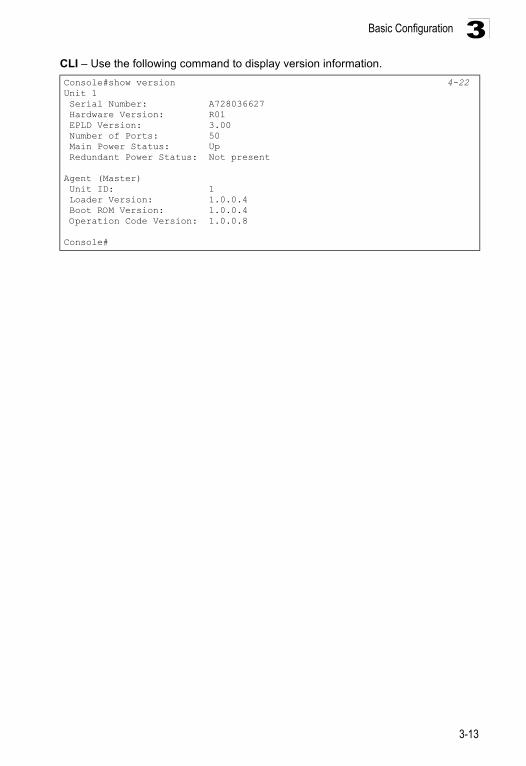
Basic Configuration 3
CLI – Use the following command to display version information.Console#show version 4-22Unit 1 Serial Number: A728036627 Hardware Version: R01 EPLD Version: 3.00 Number of Ports: 50 Main Power Status: Up Redundant Power Status: Not present
Agent (Master) Unit ID: 1 Loader Version: 1.0.0.4 Boot ROM Version: 1.0.0.4 Operation Code Version: 1.0.0.8
Console#
3-13
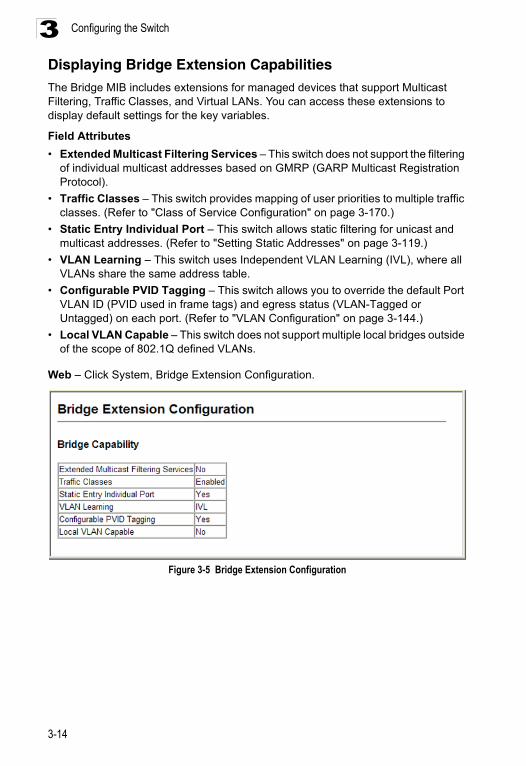
Configuring the Switch3
Displaying Bridge Extension CapabilitiesThe Bridge MIB includes extensions for managed devices that support Multicast Filtering, Traffic Classes, and Virtual LANs. You can access these extensions to display default settings for the key variables.Field Attributes
• Extended Multicast Filtering Services – This switch does not support the filtering of individual multicast addresses based on GMRP (GARP Multicast Registration Protocol).
• Traffic Classes – This switch provides mapping of user priorities to multiple traffic classes. (Refer to "Class of Service Configuration" on page 3-170.)
• Static Entry Individual Port – This switch allows static filtering for unicast and multicast addresses. (Refer to "Setting Static Addresses" on page 3-119.)
• VLAN Learning – This switch uses Independent VLAN Learning (IVL), where all VLANs share the same address table.
• Configurable PVID Tagging – This switch allows you to override the default Port VLAN ID (PVID used in frame tags) and egress status (VLAN-Tagged or Untagged) on each port. (Refer to "VLAN Configuration" on page 3-144.)
• Local VLAN Capable – This switch does not support multiple local bridges outside of the scope of 802.1Q defined VLANs.
Web – Click System, Bridge Extension Configuration.
Figure 3-5 Bridge Extension Configuration
3-14
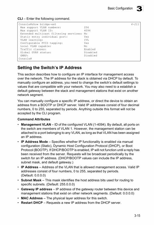
Basic Configuration 3
CLI – Enter the following command.Setting the Switch’s IP Address This section describes how to configure an IP interface for management access over the network. The IP address for the stack is obtained via DHCP by default. To manually configure an address, you need to change the switch’s default settings to values that are compatible with your network. You may also need to a establish a default gateway between the stack and management stations that exist on another network segment.
You can manually configure a specific IP address, or direct the device to obtain an address from a BOOTP or DHCP server. Valid IP addresses consist of four decimal numbers, 0 to 255, separated by periods. Anything outside this format will not be accepted by the CLI program.
Command Attributes
• Management VLAN – ID of the configured VLAN (1-4094). By default, all ports on the switch are members of VLAN 1. However, the management station can be attached to a port belonging to any VLAN, as long as that VLAN has been assigned an IP address.
• IP Address Mode – Specifies whether IP functionality is enabled via manual configuration (Static), Dynamic Host Configuration Protocol (DHCP), or Boot Protocol (BOOTP). If DHCP/BOOTP is enabled, IP will not function until a reply has been received from the server. Requests will be broadcast periodically by the switch for an IP address. (DHCP/BOOTP values can include the IP address, subnet mask, and default gateway.)
• IP Address – Address of the VLAN that is allowed management access. Valid IP addresses consist of four numbers, 0 to 255, separated by periods. (Default: 0.0.0.0)
• Subnet Mask – This mask identifies the host address bits used for routing to specific subnets. (Default: 255.0.0.0)
• Gateway IP address – IP address of the gateway router between this device and management stations that exist on other network segments. (Default: 0.0.0.0)
• MAC Address – The physical layer address for this switch. • Restart DHCP – Requests a new IP address from the DHCP server.
Console#show bridge-ext 4-211 Max support VLAN numbers: 256 Max support VLAN ID: 4094 Extended multicast filtering services: No Static entry individual port: Yes VLAN learning: IVL Configurable PVID tagging: Yes Local VLAN capable: No Traffic classes: Enabled Global GVRP status: Disabled GMRP: DisabledConsole#
3-15
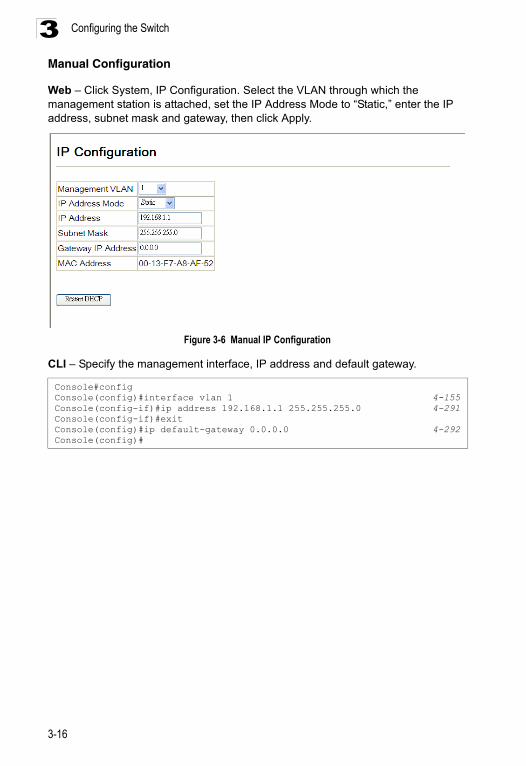
Configuring the Switch3
Manual ConfigurationWeb – Click System, IP Configuration. Select the VLAN through which the management station is attached, set the IP Address Mode to “Static,” enter the IP address, subnet mask and gateway, then click Apply.
Figure 3-6 Manual IP Configuration
CLI – Specify the management interface, IP address and default gateway.
Console#configConsole(config)#interface vlan 1 4-155Console(config-if)#ip address 192.168.1.1 255.255.255.0 4-291Console(config-if)#exitConsole(config)#ip default-gateway 0.0.0.0 4-292Console(config)#
3-16
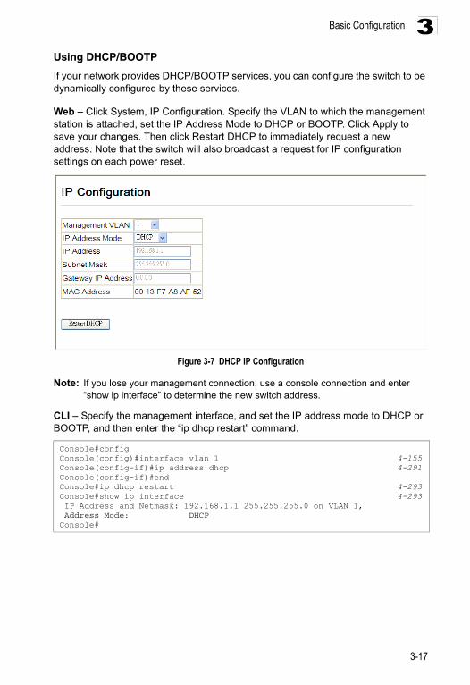
Basic Configuration 3
Using DHCP/BOOTPIf your network provides DHCP/BOOTP services, you can configure the switch to be dynamically configured by these services.
Web – Click System, IP Configuration. Specify the VLAN to which the management station is attached, set the IP Address Mode to DHCP or BOOTP. Click Apply to save your changes. Then click Restart DHCP to immediately request a new address. Note that the switch will also broadcast a request for IP configuration settings on each power reset.
Figure 3-7 DHCP IP Configuration
Note: If you lose your management connection, use a console connection and enter “show ip interface” to determine the new switch address.
CLI – Specify the management interface, and set the IP address mode to DHCP or BOOTP, and then enter the “ip dhcp restart” command.
Console#configConsole(config)#interface vlan 1 4-155Console(config-if)#ip address dhcp 4-291Console(config-if)#endConsole#ip dhcp restart 4-293Console#show ip interface 4-293 IP Address and Netmask: 192.168.1.1 255.255.255.0 on VLAN 1, Address Mode: DHCPConsole#
3-17
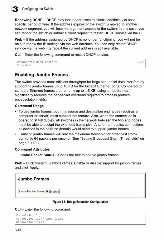
Configuring the Switch3
Renewing DCHP – DHCP may lease addresses to clients indefinitely or for a specific period of time. If the address expires or the switch is moved to another network segment, you will lose management access to the switch. In this case, you can reboot the switch or submit a client request to restart DHCP service via the CLI.Web – If the address assigned by DHCP is no longer functioning, you will not be able to renew the IP settings via the web interface. You can only restart DHCP service via the web interface if the current address is still available.
CLI – Enter the following command to restart DHCP service.
Enabling Jumbo Frames
The switch provides more efficient throughput for large sequential data transfers by supporting jumbo frames up to 10 KB for the Gigabit Ethernet ports. Compared to standard Ethernet frames that run only up to 1.5 KB, using jumbo frames significantly reduces the per-packet overhead required to process protocol encapsulation fields.
Command Usage
• To use jumbo frames, both the source and destination end nodes (such as a computer or server) must support this feature. Also, when the connection is operating at full duplex, all switches in the network between the two end nodes must be able to accept the extended frame size. And for half-duplex connections, all devices in the collision domain would need to support jumbo frames.
• Enabling jumbo frames will limit the maximum threshold for broadcast storm control to 64 packets per second. (See "Setting Broadcast Storm Thresholds" on page 3-110.)
Command Attributes
Jumbo Packet Status – Check the box to enable jumbo frames.
Web – Click System, Jumbo Frames. Enable or disable support for jumbo frames, and click Apply.
Figure 3-8 Bridge Extension Configuration
CLI – Enter the following command.
Console#ip dhcp restart 4-293Console#
Console#configConsole(config)#jumbo frameConsole(config)#
3-18
Basic Configuration 3
Managing FirmwareJust specify the method of file transfer, along with the file type and file names as required. By saving run-time code to a file on a TFTP server, that file can later be downloaded to the switch to restore operation.Only two copies of the system software (i.e., the run-time firmware) can be stored in the file directory on the switch. When downloading run-time code, the destination file name can be specified to replace the current run-time code file, or the file can be first downloaded using a different name from the current run-time code file, and then the new file set as the startup file.
Command Attributes
• File Transfer Method – The firmware copy operation includes these options:
- file to file – Copies a file within the switch directory, assigning it a new name.- file to tftp – Copies a file from the switch to a TFTP server.- tftp to file – Copies a file from a TFTP server to the switch.
• TFTP Server IP Address – The IP address of a TFTP server.
• File Type – Specify opcode (operational code) to copy firmware.
• File Name – The file name should not contain slashes (\ or /), the leading letter of the file name should not be a period (.), and the maximum length for file names on the TFTP server is 127 characters or 31 characters for files on the switch. (Valid characters: A-Z, a-z, 0-9, “.”, “-”, “_”)
Note: Up to two copies of the system software (i.e., the runtime firmware) can be stored in the file directory on the switch. The currently designated startup version of this file cannot be deleted.
Downloading System Software from a Server
When downloading runtime code, you can specify the destination file name to replace the current image, or first download the file using a different name from the current runtime code file, and then set the new file as the startup file.
3-19
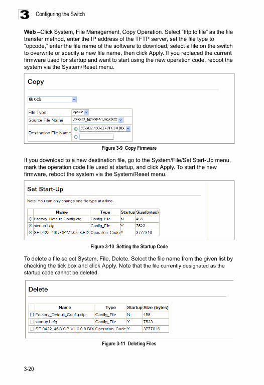
Configuring the Switch3
Web –Click System, File Management, Copy Operation. Select “tftp to file” as the file transfer method, enter the IP address of the TFTP server, set the file type to “opcode,” enter the file name of the software to download, select a file on the switch to overwrite or specify a new file name, then click Apply. If you replaced the current firmware used for startup and want to start using the new operation code, reboot the system via the System/Reset menu.Figure 3-9 Copy Firmware
If you download to a new destination file, go to the System/File/Set Start-Up menu, mark the operation code file used at startup, and click Apply. To start the new firmware, reboot the system via the System/Reset menu.
Figure 3-10 Setting the Startup Code
To delete a file select System, File, Delete. Select the file name from the given list by checking the tick box and click Apply. Note that the file currently designated as the startup code cannot be deleted.
Figure 3-11 Deleting Files
3-20

Basic Configuration 3
CLI – To download new firmware form a TFTP server, enter the IP address of the TFTP server, select “opcode” as the file type, then enter the source and destination file names. When the file has finished downloading, set the new file to start up the system, and then restart the switch.To start the new firmware, enter the “reload” command or reboot the system.
Saving or Restoring Configuration Settings
You can upload/download configuration settings to/from a TFTP server. The configuration files can be later downloaded to restore the switch’s settings.
Command Attributes
• File Transfer Method – The configuration copy operation includes these options:
- file to file – Copies a file within the switch directory, assigning it a new name.- file to running-config – Copies a file in the switch to the running configuration.- file to startup-config – Copies a file in the switch to the startup configuration.- file to tftp – Copies a file from the switch to a TFTP server.- running-config to file – Copies the running configuration to a file.- running-config to startup-config – Copies the running config to the startup config.- running-config to tftp – Copies the running configuration to a TFTP server.- startup-config to file – Copies the startup configuration to a file on the switch.- startup-config to running-config – Copies the startup config to the running config.- startup-config to tftp – Copies the startup configuration to a TFTP server.- tftp to file – Copies a file from a TFTP server to the switch.- tftp to running-config – Copies a file from a TFTP server to the running config.- tftp to startup-config – Copies a file from a TFTP server to the startup config.
• TFTP Server IP Address – The IP address of a TFTP server.
• File Type – Specify config (configuration) to copy configuration settings.
• File Name — The file name should not contain slashes (\ or /), the leading letter of the file name should not be a period (.), and the maximum length for file names on the TFTP server is 127 characters or 31 characters for files on the switch. (Valid characters: A-Z, a-z, 0-9, “.”, “-”, “_”)
Note: The maximum number of user-defined configuration files is limited only by available flash memory space.
Console#copy tftp file 4-25TFTP server ip address: 192.168.1.23Choose file type: 1. config: 2. opcode: <1-2>: 2Source file name: SF-0422_46G-OP-V1.0.0.8.BIXDestination file name: V1008.F\Write to FLASH Programming.-Write to FLASH finish.Success.Console#configConsole(config)#boot system opcode:V1008.F 4-30Console(config)#exitConsole#reload 4-13
3-21
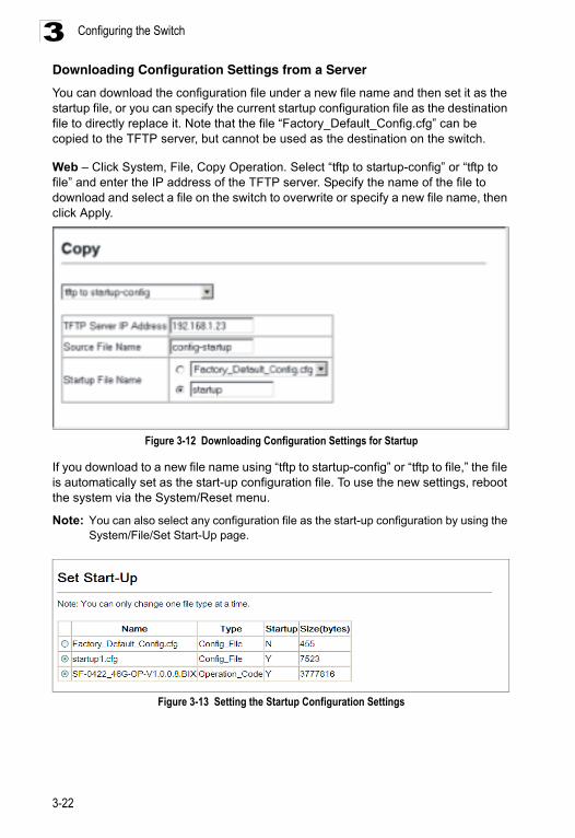
Configuring the Switch3
Downloading Configuration Settings from a ServerYou can download the configuration file under a new file name and then set it as the startup file, or you can specify the current startup configuration file as the destination file to directly replace it. Note that the file “Factory_Default_Config.cfg” can be copied to the TFTP server, but cannot be used as the destination on the switch.
Web – Click System, File, Copy Operation. Select “tftp to startup-config” or “tftp to file” and enter the IP address of the TFTP server. Specify the name of the file to download and select a file on the switch to overwrite or specify a new file name, then click Apply.
Figure 3-12 Downloading Configuration Settings for Startup
If you download to a new file name using “tftp to startup-config” or “tftp to file,” the file is automatically set as the start-up configuration file. To use the new settings, reboot the system via the System/Reset menu.
Note: You can also select any configuration file as the start-up configuration by using the System/File/Set Start-Up page.
Figure 3-13 Setting the Startup Configuration Settings
3-22
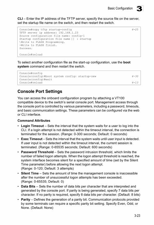
Basic Configuration 3
CLI – Enter the IP address of the TFTP server, specify the source file on the server, set the startup file name on the switch, and then restart the switch.To select another configuration file as the start-up configuration, use the boot system command and then restart the switch.
Console Port SettingsYou can access the onboard configuration program by attaching a VT100 compatible device to the switch’s serial console port. Management access through the console port is controlled by various parameters, including a password, timeouts, and basic communication settings. These parameters can be configured via the web or CLI interface.
Command Attributes
• Login Timeout – Sets the interval that the system waits for a user to log into the CLI. If a login attempt is not detected within the timeout interval, the connection is terminated for the session. (Range: 0-300 seconds; Default: 0 seconds)
• Exec Timeout – Sets the interval that the system waits until user input is detected. If user input is not detected within the timeout interval, the current session is terminated. (Range: 0-65535 seconds; Default: 600 seconds)
• Password Threshold – Sets the password intrusion threshold, which limits the number of failed logon attempts. When the logon attempt threshold is reached, the system interface becomes silent for a specified amount of time (set by the Silent Time parameter) before allowing the next logon attempt. (Range: 0-120; Default: 3 attempts)
• Silent Time – Sets the amount of time the management console is inaccessible after the number of unsuccessful logon attempts has been exceeded. (Range: 0-65535; Default: 0)
• Data Bits – Sets the number of data bits per character that are interpreted and generated by the console port. If parity is being generated, specify 7 data bits per character. If no parity is required, specify 8 data bits per character. (Default: 8 bits)
• Parity – Defines the generation of a parity bit. Communication protocols provided by some terminals can require a specific parity bit setting. Specify Even, Odd, or None. (Default: None)
Console#copy tftp startup-config 4-25TFTP server ip address: 192.168.1.23Source configuration file name: config-1Startup configuration file name [] : startup\Write to FLASH Programming.-Write to FLASH finish.Success.
Console#reload
Console#configConsole(config)#boot system config: startup-new 4-30Console(config)#exitConsole#reload 4-13
3-23
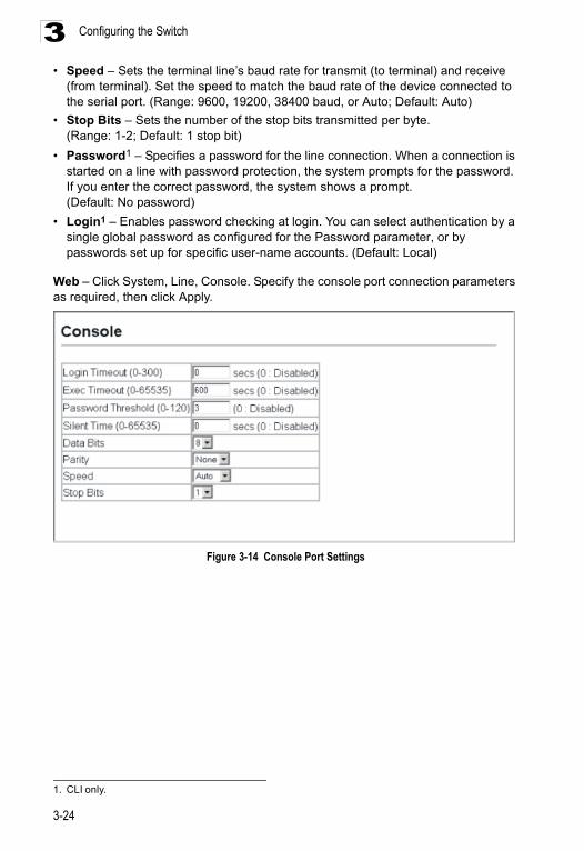
Configuring the Switch3
• Speed – Sets the terminal line’s baud rate for transmit (to terminal) and receive(from terminal). Set the speed to match the baud rate of the device connected to the serial port. (Range: 9600, 19200, 38400 baud, or Auto; Default: Auto)
• Stop Bits – Sets the number of the stop bits transmitted per byte. (Range: 1-2; Default: 1 stop bit)
• Password1 – Specifies a password for the line connection. When a connection is started on a line with password protection, the system prompts for the password. If you enter the correct password, the system shows a prompt. (Default: No password)
• Login1 – Enables password checking at login. You can select authentication by a single global password as configured for the Password parameter, or by passwords set up for specific user-name accounts. (Default: Local)
Web – Click System, Line, Console. Specify the console port connection parameters as required, then click Apply.
Figure 3-14 Console Port Settings
1. CLI only.
3-24
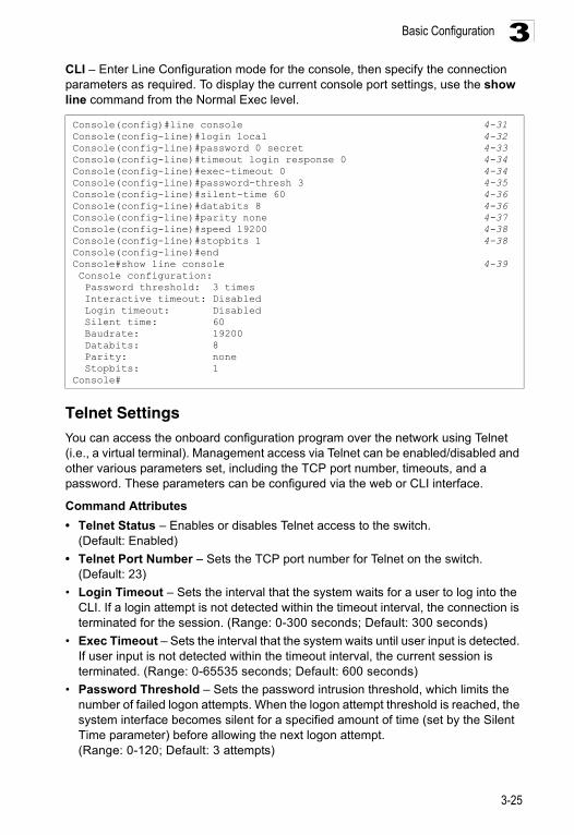
Basic Configuration 3
CLI – Enter Line Configuration mode for the console, then specify the connection parameters as required. To display the current console port settings, use the show line command from the Normal Exec level.Telnet SettingsYou can access the onboard configuration program over the network using Telnet (i.e., a virtual terminal). Management access via Telnet can be enabled/disabled and other various parameters set, including the TCP port number, timeouts, and a password. These parameters can be configured via the web or CLI interface.
Command Attributes
• Telnet Status – Enables or disables Telnet access to the switch. (Default: Enabled)
• Telnet Port Number – Sets the TCP port number for Telnet on the switch. (Default: 23)
• Login Timeout – Sets the interval that the system waits for a user to log into the CLI. If a login attempt is not detected within the timeout interval, the connection is terminated for the session. (Range: 0-300 seconds; Default: 300 seconds)
• Exec Timeout – Sets the interval that the system waits until user input is detected. If user input is not detected within the timeout interval, the current session is terminated. (Range: 0-65535 seconds; Default: 600 seconds)
• Password Threshold – Sets the password intrusion threshold, which limits the number of failed logon attempts. When the logon attempt threshold is reached, the system interface becomes silent for a specified amount of time (set by the Silent Time parameter) before allowing the next logon attempt. (Range: 0-120; Default: 3 attempts)
Console(config)#line console 4-31Console(config-line)#login local 4-32Console(config-line)#password 0 secret 4-33Console(config-line)#timeout login response 0 4-34Console(config-line)#exec-timeout 0 4-34Console(config-line)#password-thresh 3 4-35Console(config-line)#silent-time 60 4-36Console(config-line)#databits 8 4-36Console(config-line)#parity none 4-37Console(config-line)#speed 19200 4-38Console(config-line)#stopbits 1 4-38Console(config-line)#endConsole#show line console 4-39 Console configuration: Password threshold: 3 times Interactive timeout: Disabled Login timeout: Disabled Silent time: 60 Baudrate: 19200 Databits: 8 Parity: none Stopbits: 1Console#
3-25
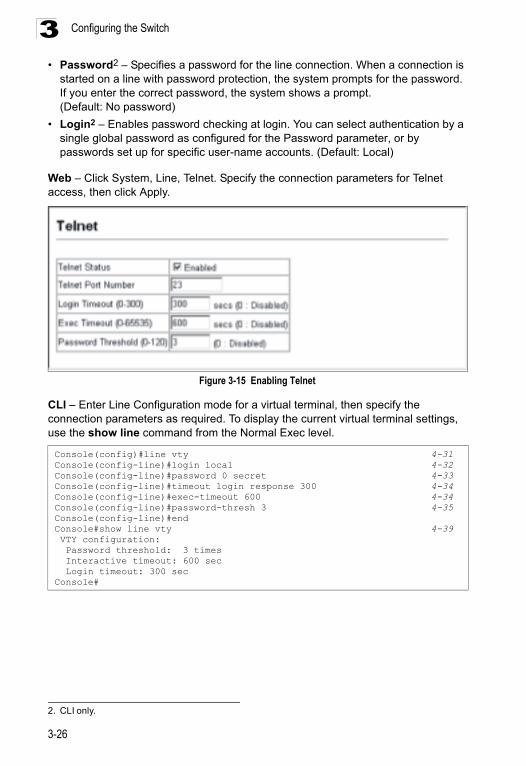
Configuring the Switch3
• Password2 – Specifies a password for the line connection. When a connection isstarted on a line with password protection, the system prompts for the password. If you enter the correct password, the system shows a prompt. (Default: No password)
• Login2 – Enables password checking at login. You can select authentication by a single global password as configured for the Password parameter, or by passwords set up for specific user-name accounts. (Default: Local)
Web – Click System, Line, Telnet. Specify the connection parameters for Telnet access, then click Apply.
Figure 3-15 Enabling Telnet
CLI – Enter Line Configuration mode for a virtual terminal, then specify the connection parameters as required. To display the current virtual terminal settings, use the show line command from the Normal Exec level.
2. CLI only.
Console(config)#line vty 4-31Console(config-line)#login local 4-32Console(config-line)#password 0 secret 4-33Console(config-line)#timeout login response 300 4-34Console(config-line)#exec-timeout 600 4-34Console(config-line)#password-thresh 3 4-35Console(config-line)#endConsole#show line vty 4-39 VTY configuration: Password threshold: 3 times Interactive timeout: 600 sec Login timeout: 300 secConsole#
3-26
Basic Configuration 3
Configuring Event LoggingThe switch allows you to control the logging of error messages, including the type of events that are recorded in switch memory, logging to a remote System Log (syslog) server, and displays a list of recent event messages.System Log ConfigurationThe system allows you to enable or disable event logging, and specify which levels are logged to RAM or flash memory.
Severe error messages that are logged to flash memory are permanently stored in the switch to assist in troubleshooting network problems. Up to 4096 log entries can be stored in the flash memory, with the oldest entries being overwritten first when the available log memory (256 kilobytes) has been exceeded.
The System Logs page allows you to configure and limit system messages that are logged to flash or RAM memory. The default is for event levels 0 to 3 to be logged to flash and levels 0 to 7 to be logged to RAM.
Command Attributes
• System Log Status – Enables/disables the logging of debug or error messages to the logging process. (Default: Enabled)
• Flash Level – Limits log messages saved to the switch’s permanent flash memory for all levels up to the specified level. For example, if level 3 is specified, all messages from level 0 to level 3 will be logged to flash. (Range: 0-7, Default: 3)
• RAM Level – Limits log messages saved to the switch’s temporary RAM memory for all levels up to the specified level. For example, if level 7 is specified, all messages from level 0 to level 7 will be logged to RAM. (Range: 0-7, Default: 7)
Note: The Flash Level must be equal to or less than the RAM Level.
Table 3-3 Logging Levels
Level Severity Name Description
7 Debug Debugging messages
6 Informational Informational messages only
5 Notice Normal but significant condition, such as cold start
4 Warning Warning conditions (e.g., return false, unexpected return)
3 Error Error conditions (e.g., invalid input, default used)
2 Critical Critical conditions (e.g., memory allocation, or free memory error - resource exhausted)
1 Alert Immediate action needed
0 Emergency System unusable
* There are only Level 2, 5 and 6 error messages for the current firmware release.
3-27
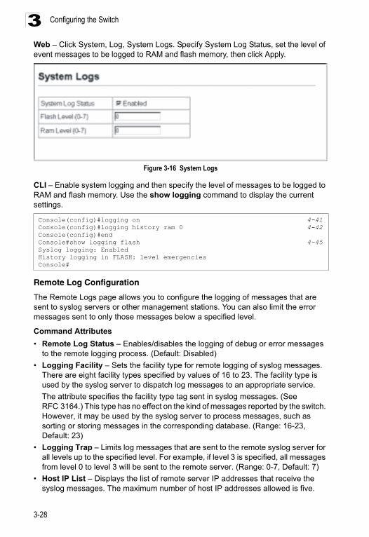
Configuring the Switch3
Web – Click System, Log, System Logs. Specify System Log Status, set the level of event messages to be logged to RAM and flash memory, then click Apply.Figure 3-16 System Logs
CLI – Enable system logging and then specify the level of messages to be logged to RAM and flash memory. Use the show logging command to display the current settings.
Remote Log Configuration
The Remote Logs page allows you to configure the logging of messages that are sent to syslog servers or other management stations. You can also limit the error messages sent to only those messages below a specified level.
Command Attributes
• Remote Log Status – Enables/disables the logging of debug or error messages to the remote logging process. (Default: Disabled)
• Logging Facility – Sets the facility type for remote logging of syslog messages. There are eight facility types specified by values of 16 to 23. The facility type is used by the syslog server to dispatch log messages to an appropriate service.
The attribute specifies the facility type tag sent in syslog messages. (See RFC 3164.) This type has no effect on the kind of messages reported by the switch. However, it may be used by the syslog server to process messages, such as sorting or storing messages in the corresponding database. (Range: 16-23, Default: 23)
• Logging Trap – Limits log messages that are sent to the remote syslog server for all levels up to the specified level. For example, if level 3 is specified, all messages from level 0 to level 3 will be sent to the remote server. (Range: 0-7, Default: 7)
• Host IP List – Displays the list of remote server IP addresses that receive the syslog messages. The maximum number of host IP addresses allowed is five.
Console(config)#logging on 4-41Console(config)#logging history ram 0 4-42Console(config)#endConsole#show logging flash 4-45Syslog logging: EnabledHistory logging in FLASH: level emergenciesConsole#
3-28
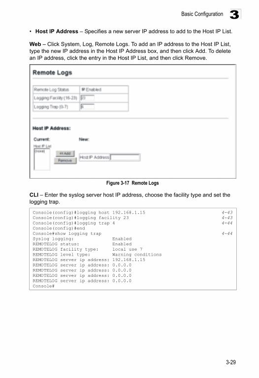
Basic Configuration 3
• Host IP Address – Specifies a new server IP address to add to the Host IP List.Web – Click System, Log, Remote Logs. To add an IP address to the Host IP List, type the new IP address in the Host IP Address box, and then click Add. To delete an IP address, click the entry in the Host IP List, and then click Remove.
Figure 3-17 Remote Logs
CLI – Enter the syslog server host IP address, choose the facility type and set the logging trap.
Console(config)#logging host 192.168.1.15 4-43Console(config)#logging facility 23 4-43Console(config)#logging trap 4 4-44Console(config)#endConsole#show logging trap 4-44Syslog logging: EnabledREMOTELOG status: EnabledREMOTELOG facility type: local use 7REMOTELOG level type: Warning conditionsREMOTELOG server ip address: 192.168.1.15REMOTELOG server ip address: 0.0.0.0REMOTELOG server ip address: 0.0.0.0REMOTELOG server ip address: 0.0.0.0REMOTELOG server ip address: 0.0.0.0Console#
3-29
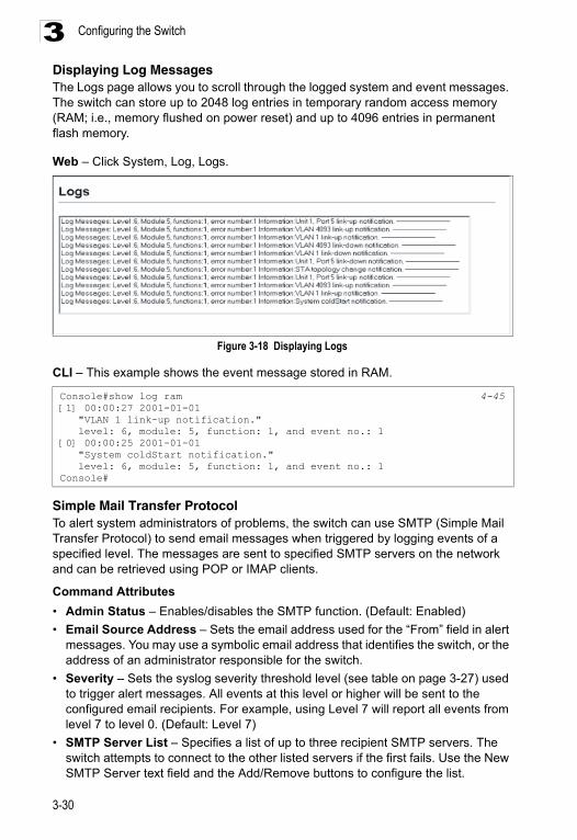
Configuring the Switch3
Displaying Log MessagesThe Logs page allows you to scroll through the logged system and event messages. The switch can store up to 2048 log entries in temporary random access memory (RAM; i.e., memory flushed on power reset) and up to 4096 entries in permanent flash memory.Web – Click System, Log, Logs.
Figure 3-18 Displaying Logs
CLI – This example shows the event message stored in RAM.
Simple Mail Transfer ProtocolTo alert system administrators of problems, the switch can use SMTP (Simple Mail Transfer Protocol) to send email messages when triggered by logging events of a specified level. The messages are sent to specified SMTP servers on the network and can be retrieved using POP or IMAP clients.
Command Attributes
• Admin Status – Enables/disables the SMTP function. (Default: Enabled)
• Email Source Address – Sets the email address used for the “From” field in alert messages. You may use a symbolic email address that identifies the switch, or the address of an administrator responsible for the switch.
• Severity – Sets the syslog severity threshold level (see table on page 3-27) used to trigger alert messages. All events at this level or higher will be sent to the configured email recipients. For example, using Level 7 will report all events from level 7 to level 0. (Default: Level 7)
• SMTP Server List – Specifies a list of up to three recipient SMTP servers. The switch attempts to connect to the other listed servers if the first fails. Use the New SMTP Server text field and the Add/Remove buttons to configure the list.
Console#show log ram 4-45[1] 00:00:27 2001-01-01 "VLAN 1 link-up notification." level: 6, module: 5, function: 1, and event no.: 1[0] 00:00:25 2001-01-01 "System coldStart notification." level: 6, module: 5, function: 1, and event no.: 1Console#
3-30
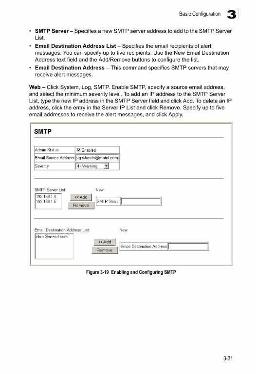
Basic Configuration 3
• SMTP Server – Specifies a new SMTP server address to add to the SMTP ServerList.
• Email Destination Address List – Specifies the email recipients of alert messages. You can specify up to five recipients. Use the New Email Destination Address text field and the Add/Remove buttons to configure the list.
• Email Destination Address – This command specifies SMTP servers that may receive alert messages.
Web – Click System, Log, SMTP. Enable SMTP, specify a source email address, and select the minimum severity level. To add an IP address to the SMTP Server List, type the new IP address in the SMTP Server field and click Add. To delete an IP address, click the entry in the Server IP List and click Remove. Specify up to five email addresses to receive the alert messages, and click Apply.
Figure 3-19 Enabling and Configuring SMTP
3-31
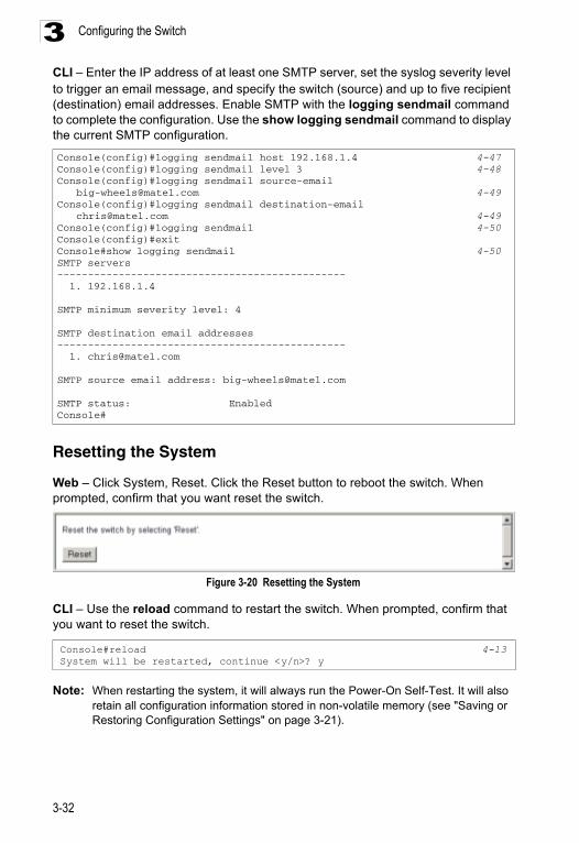
Configuring the Switch3
CLI – Enter the IP address of at least one SMTP server, set the syslog severity level to trigger an email message, and specify the switch (source) and up to five recipient (destination) email addresses. Enable SMTP with the logging sendmail command to complete the configuration. Use the show logging sendmail command to display the current SMTP configuration.Resetting the System
Web – Click System, Reset. Click the Reset button to reboot the switch. When prompted, confirm that you want reset the switch.
Figure 3-20 Resetting the System
CLI – Use the reload command to restart the switch. When prompted, confirm that you want to reset the switch.
Note: When restarting the system, it will always run the Power-On Self-Test. It will also retain all configuration information stored in non-volatile memory (see "Saving or Restoring Configuration Settings" on page 3-21).
Console(config)#logging sendmail host 192.168.1.4 4-47Console(config)#logging sendmail level 3 4-48Console(config)#logging sendmail source-email
[email protected] 4-49Console(config)#logging sendmail destination-email
[email protected] 4-49Console(config)#logging sendmail 4-50Console(config)#exitConsole#show logging sendmail 4-50SMTP servers----------------------------------------------- 1. 192.168.1.4
SMTP minimum severity level: 4
SMTP destination email addresses----------------------------------------------- 1. [email protected]
SMTP source email address: [email protected]
SMTP status: EnabledConsole#
Console#reload 4-13System will be restarted, continue <y/n>? y
3-32
Basic Configuration 3
Setting the System ClockSimple Network Time Protocol (SNTP) allows the switch to set its internal clock based on periodic updates from a time server (SNTP or NTP). Maintaining an accurate time on the switch enables the system log to record meaningful dates and times for event entries. You can also manually set the clock using the CLI. (See "calendar set" on page 4-55) If the clock is not set, the switch will only record the time from the factory default set at the last bootup.When the SNTP client is enabled, the switch periodically sends a request for a time update to a configured time server. You can configure up to three time server IP addresses. The switch will attempt to poll each server in the configured sequence.
Setting the Time Manually
You can set the system time on the switch manually without using SNTP.
CLI – This example sets the system clock time and then displays the current time and date.
Configuring SNTPYou can configure the switch to send time synchronization requests to time servers.
Command Attributes
• SNTP Client – Configures the switch to operate as an SNTP client. This requires at least one NTP or SNTP time server to be specified in the SNTP Server field. (Default: Disabled)
• SNTP Poll Interval – Sets the interval between sending requests for a time update from a time server. (Range: 16-16384 seconds; Default: 16 seconds)
• SNTP Server – Sets the IP address for up to three time servers. The switch attempts to update the time from the first server, if this fails it attempts an update from the next server in the sequence.
Console#calendar set 17 46 00 october 18 2008 4-55Console#show calendar 4-55 17:46:11 October 18 2008Console#
3-33
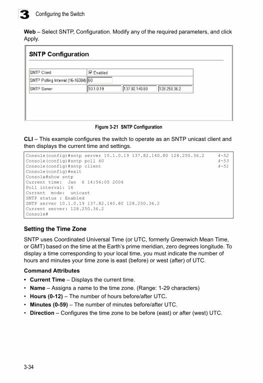
Configuring the Switch3
Web – Select SNTP, Configuration. Modify any of the required parameters, and click Apply.Figure 3-21 SNTP Configuration
CLI – This example configures the switch to operate as an SNTP unicast client and then displays the current time and settings.
Setting the Time Zone
SNTP uses Coordinated Universal Time (or UTC, formerly Greenwich Mean Time, or GMT) based on the time at the Earth’s prime meridian, zero degrees longitude. To display a time corresponding to your local time, you must indicate the number of hours and minutes your time zone is east (before) or west (after) of UTC.
Command Attributes
• Current Time – Displays the current time.
• Name – Assigns a name to the time zone. (Range: 1-29 characters)
• Hours (0-12) – The number of hours before/after UTC.
• Minutes (0-59) – The number of minutes before/after UTC.
• Direction – Configures the time zone to be before (east) or after (west) UTC.
Console(config)#sntp server 10.1.0.19 137.82.140.80 128.250.36.2 4-52Console(config)#sntp poll 60 4-53Console(config)#sntp client 4-51Console(config)#exitConsole#show sntpCurrent time: Jan 6 14:56:05 2004Poll interval: 16Current mode: unicastSNTP status : EnabledSNTP server 10.1.0.19 137.82.140.80 128.250.36.2Current server: 128.250.36.2Console#
3-34
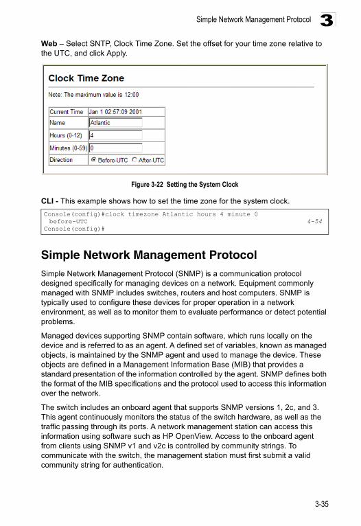
Simple Network Management Protocol 3
Web – Select SNTP, Clock Time Zone. Set the offset for your time zone relative to the UTC, and click Apply.Figure 3-22 Setting the System Clock
CLI - This example shows how to set the time zone for the system clock.
Simple Network Management Protocol Simple Network Management Protocol (SNMP) is a communication protocol designed specifically for managing devices on a network. Equipment commonly managed with SNMP includes switches, routers and host computers. SNMP is typically used to configure these devices for proper operation in a network environment, as well as to monitor them to evaluate performance or detect potential problems.
Managed devices supporting SNMP contain software, which runs locally on the device and is referred to as an agent. A defined set of variables, known as managed objects, is maintained by the SNMP agent and used to manage the device. These objects are defined in a Management Information Base (MIB) that provides a standard presentation of the information controlled by the agent. SNMP defines both the format of the MIB specifications and the protocol used to access this information over the network.
The switch includes an onboard agent that supports SNMP versions 1, 2c, and 3. This agent continuously monitors the status of the switch hardware, as well as the traffic passing through its ports. A network management station can access this information using software such as HP OpenView. Access to the onboard agent from clients using SNMP v1 and v2c is controlled by community strings. To communicate with the switch, the management station must first submit a valid community string for authentication.
Console(config)#clock timezone Atlantic hours 4 minute 0 before-UTC 4-54
Console(config)#
3-35
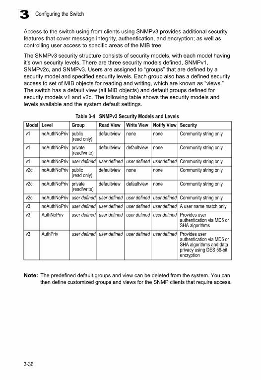
Configuring the Switch3
Access to the switch using from clients using SNMPv3 provides additional security features that cover message integrity, authentication, and encryption; as well as controlling user access to specific areas of the MIB tree.The SNMPv3 security structure consists of security models, with each model having it’s own security levels. There are three security models defined, SNMPv1, SNMPv2c, and SNMPv3. Users are assigned to “groups” that are defined by a security model and specified security levels. Each group also has a defined security access to set of MIB objects for reading and writing, which are known as “views.” The switch has a default view (all MIB objects) and default groups defined for security models v1 and v2c. The following table shows the security models and levels available and the system default settings.
Note: The predefined default groups and view can be deleted from the system. You can then define customized groups and views for the SNMP clients that require access.
Table 3-4 SNMPv3 Security Models and Levels
Model Level Group Read View Write View Notify View Security
v1 noAuthNoPriv public (read only)
defaultview none none Community string only
v1 noAuthNoPriv private (read/write)
defaultview defaultview none Community string only
v1 noAuthNoPriv user defined user defined user defined user defined Community string only
v2c noAuthNoPriv public (read only)
defaultview none none Community string only
v2c noAuthNoPriv private (read/write)
defaultview defaultview none Community string only
v2c noAuthNoPriv user defined user defined user defined user defined Community string only
v3 noAuthNoPriv user defined user defined user defined user defined A user name match only
v3 AuthNoPriv user defined user defined user defined user defined Provides user authentication via MD5 or SHA algorithms
v3 AuthPriv user defined user defined user defined user defined Provides user authentication via MD5 or SHA algorithms and data privacy using DES 56-bit encryption
3-36
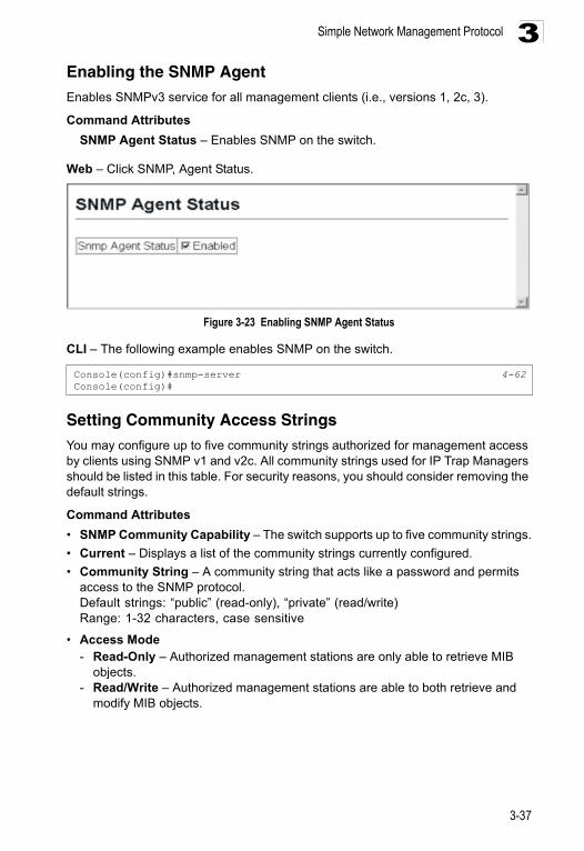
Simple Network Management Protocol 3
Enabling the SNMP AgentEnables SNMPv3 service for all management clients (i.e., versions 1, 2c, 3).Command Attributes
SNMP Agent Status – Enables SNMP on the switch.
Web – Click SNMP, Agent Status.
Figure 3-23 Enabling SNMP Agent Status
CLI – The following example enables SNMP on the switch.
Setting Community Access Strings You may configure up to five community strings authorized for management access by clients using SNMP v1 and v2c. All community strings used for IP Trap Managers should be listed in this table. For security reasons, you should consider removing the default strings.
Command Attributes
• SNMP Community Capability – The switch supports up to five community strings.
• Current – Displays a list of the community strings currently configured.
• Community String – A community string that acts like a password and permits access to the SNMP protocol. Default strings: “public” (read-only), “private” (read/write)Range: 1-32 characters, case sensitive
• Access Mode - Read-Only – Authorized management stations are only able to retrieve MIB
objects. - Read/Write – Authorized management stations are able to both retrieve and
modify MIB objects.
Console(config)#snmp-server 4-62Console(config)#
3-37
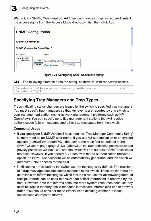
Configuring the Switch3
Web – Click SNMP, Configuration. Add new community strings as required, select the access rights from the Access Mode drop-down list, then click Add.Figure 3-24 Configuring SNMP Community Strings
CLI – The following example adds the string “spiderman” with read/write access.
Specifying Trap Managers and Trap TypesTraps indicating status changes are issued by the switch to specified trap managers. You must specify trap managers so that key events are reported by this switch to your management station (using network management platforms such as HP OpenView). You can specify up to five management stations that will receive authentication failure messages and other trap messages from the switch.
Command Usage
• If you specify an SNMP Version 3 host, then the “Trap Manager Community String” is interpreted as an SNMP user name. If you use V3 authentication or encryption options (authNoPriv or authPriv), the user name must first be defined in the SNMPv3 Users page (page 3-43). Otherwise, the authentication password and/or privacy password will not exist, and the switch will not authorize SNMP access for the host. However, if you specify a V3 host with the no authentication (noAuth) option, an SNMP user account will be automatically generated, and the switch will authorize SNMP access for the host.
• Notifications are issued by the switch as trap messages by default. The recipient of a trap message does not send a response to the switch. Traps are therefore not as reliable as inform messages, which include a request for acknowledgement of receipt. Informs can be used to ensure that critical information is received by the host. However, note that informs consume more system resources because they must be kept in memory until a response is received. Informs also add to network traffic. You should consider these effects when deciding whether to issue notifications as traps or informs.
Console(config)#snmp-server community spiderman rw 4-63Console(config)#
3-38
Simple Network Management Protocol 3
To send an inform to a SNMPv2c host, complete these steps:1. Enable the SNMP agent (page 3-37).2. Enable trap informs as described in the following pages.3. Create a view with the required notification messages (page 3-50).4. Create a group that includes the required notify view (page 3-47).To send an inform to a SNMPv3 host, complete these steps:1. Enable the SNMP agent (page 3-37).2. Enable trap informs as described in the following pages.3. Create a view with the required notification messages (page 3-50).4. Create a group that includes the required notify view (page 3-47).5. Specify a remote engine ID where the user resides (page 3-42).6. Then configure a remote user (page 3-45).
Command Attributes
• Trap Manager Capability – This switch supports up to five trap managers.
• Current – Displays a list of the trap managers currently configured.
• Trap Manager IP Address – IP address of a new management station to receive notification message (i.e., the targeted recipient).
• Trap Manager Community String – Specifies a valid community string for the new trap manager entry. Though you can set this string in the Trap Managers table, we recommend that you define this string in the SNMP Community section at the top of the SNMP Configuration page (for Version 1 or 2c clients), or define a corresponding “User Name” in the SNMPv3 Users page (for Version 3 clients). (Range: 1-32 characters, case sensitive)
• Trap UDP Port – Specifies the UDP port number used by the trap manager. (Default: 162)
• Trap Version – Specifies whether to send notifications as SNMP v1, v2c, or v3 traps. (Default: v1)
• Trap Security Level – When trap version 3 is selected, you must specify one of the following security levels. (Default: noAuthNoPriv)
- noAuthNoPriv – There is no authentication or encryption used in SNMP communications.
- AuthNoPriv – SNMP communications use authentication, but the data is not encrypted (only available for the SNMPv3 security model).
- AuthPriv – SNMP communications use both authentication and encryption (only available for the SNMPv3 security model).
• Trap Inform – Notifications are sent as inform messages. Note that this option is only available for version 2c and 3 hosts. (Default: traps are used)
- Timeout – The number of seconds to wait for an acknowledgment before resending an inform message. (Range: 0-2147483647 centiseconds; Default: 1500 centiseconds)
- Retry times – The maximum number of times to resend an inform message if the recipient does not acknowledge receipt. (Range: 0-255; Default: 3)
3-39
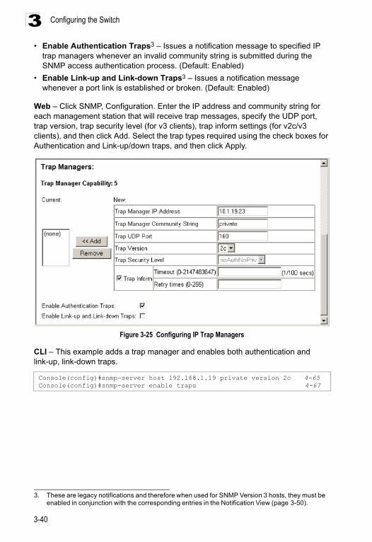
Configuring the Switch3
• Enable Authentication Traps3 – Issues a notification message to specified IPtrap managers whenever an invalid community string is submitted during the SNMP access authentication process. (Default: Enabled)
• Enable Link-up and Link-down Traps3 – Issues a notification message whenever a port link is established or broken. (Default: Enabled)
Web – Click SNMP, Configuration. Enter the IP address and community string for each management station that will receive trap messages, specify the UDP port, trap version, trap security level (for v3 clients), trap inform settings (for v2c/v3 clients), and then click Add. Select the trap types required using the check boxes for Authentication and Link-up/down traps, and then click Apply.
Figure 3-25 Configuring IP Trap Managers
CLI – This example adds a trap manager and enables both authentication and link-up, link-down traps.
3. These are legacy notifications and therefore when used for SNMP Version 3 hosts, they must be enabled in conjunction with the corresponding entries in the Notification View (page 3-50).
Console(config)#snmp-server host 192.168.1.19 private version 2c 4-65Console(config)#snmp-server enable traps 4-67
3-40
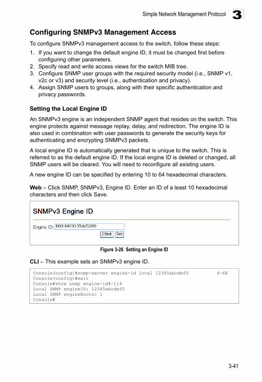
Simple Network Management Protocol 3
Configuring SNMPv3 Management AccessTo configure SNMPv3 management access to the switch, follow these steps:1. If you want to change the default engine ID, it must be changed first before configuring other parameters.
2. Specify read and write access views for the switch MIB tree.3. Configure SNMP user groups with the required security model (i.e., SNMP v1,
v2c or v3) and security level (i.e., authentication and privacy).4. Assign SNMP users to groups, along with their specific authentication and
privacy passwords.
Setting the Local Engine ID
An SNMPv3 engine is an independent SNMP agent that resides on the switch. This engine protects against message replay, delay, and redirection. The engine ID is also used in combination with user passwords to generate the security keys for authenticating and encrypting SNMPv3 packets.
A local engine ID is automatically generated that is unique to the switch. This is referred to as the default engine ID. If the local engine ID is deleted or changed, all SNMP users will be cleared. You will need to reconfigure all existing users.
A new engine ID can be specified by entering 10 to 64 hexadecimal characters.
Web – Click SNMP, SNMPv3, Engine ID. Enter an ID of a least 10 hexadecimal characters and then click Save.
Figure 3-26 Setting an Engine ID
CLI – This example sets an SNMPv3 engine ID.
Console(config)#snmp-server engine-id local 12345abcdef0 4-68Console(config)#exitConsole#show snmp engine-id4-114Local SNMP engineID: 12345abcdef0Local SNMP engineBoots: 1Console#
3-41
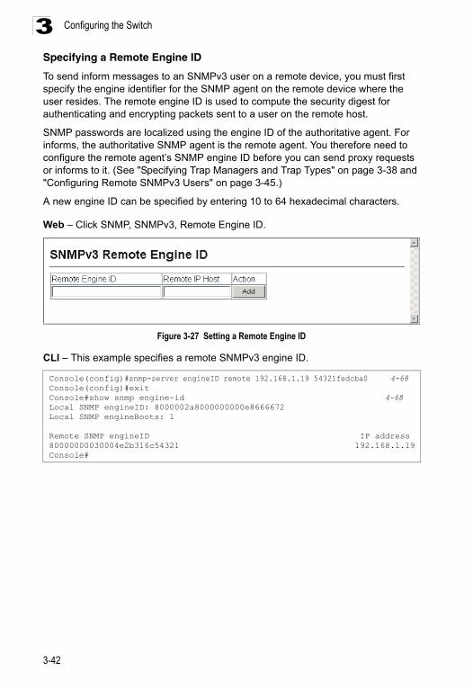
Configuring the Switch3
Specifying a Remote Engine IDTo send inform messages to an SNMPv3 user on a remote device, you must first specify the engine identifier for the SNMP agent on the remote device where the user resides. The remote engine ID is used to compute the security digest for authenticating and encrypting packets sent to a user on the remote host.
SNMP passwords are localized using the engine ID of the authoritative agent. For informs, the authoritative SNMP agent is the remote agent. You therefore need to configure the remote agent’s SNMP engine ID before you can send proxy requests or informs to it. (See "Specifying Trap Managers and Trap Types" on page 3-38 and "Configuring Remote SNMPv3 Users" on page 3-45.)
A new engine ID can be specified by entering 10 to 64 hexadecimal characters.
Web – Click SNMP, SNMPv3, Remote Engine ID.
Figure 3-27 Setting a Remote Engine ID
CLI – This example specifies a remote SNMPv3 engine ID.
Console(config)#snmp-server engineID remote 192.168.1.19 54321fedcba0 4-68Console(config)#exitConsole#show snmp engine-id 4-68Local SNMP engineID: 8000002a8000000000e8666672Local SNMP engineBoots: 1
Remote SNMP engineID IP address80000000030004e2b316c54321 192.168.1.19Console#
3-42
Simple Network Management Protocol 3
Configuring SNMPv3 UsersEach SNMPv3 user is defined by a unique name. Users must be configured with a specific security level and assigned to a group. The SNMPv3 group restricts users to a specific read, write, and notify view.
Command Attributes
• User Name – The name of user connecting to the SNMP agent. (Range: 1-32 characters)
• Group Name – The name of the SNMP group to which the user is assigned. (Range: 1-32 characters)
• Security Model – The user security model; SNMP v1, v2c or v3.• Security Level – The security level used for the user:
- noAuthNoPriv – There is no authentication or encryption used in SNMP communications. (This is the default for SNMPv3.)
- AuthNoPriv – SNMP communications use authentication, but the data is not encrypted (only available for the SNMPv3 security model).
- AuthPriv – SNMP communications use both authentication and encryption (only available for the SNMPv3 security model).
• Authentication Protocol – The method used for user authentication. (Options: MD5, SHA; Default: MD5)
• Authentication Password – A minimum of eight plain text characters is required.
• Privacy Protocol – The encryption algorithm use for data privacy; only 56-bit DES is currently available.
• Privacy Password – A minimum of eight plain text characters is required.
• Actions – Enables the user to be assigned to another SNMPv3 group.
3-43
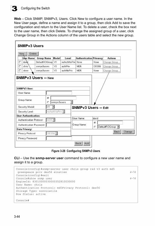
Configuring the Switch3
Web – Click SNMP, SNMPv3, Users. Click New to configure a user name. In the New User page, define a name and assign it to a group, then click Add to save the configuration and return to the User Name list. To delete a user, check the box next to the user name, then click Delete. To change the assigned group of a user, click Change Group in the Actions column of the users table and select the new group.Figure 3-28 Configuring SNMPv3 Users
CLI – Use the snmp-server user command to configure a new user name and assign it to a group.
Console(config)#snmp-server user chris group r&d v3 auth md5 greenpeace priv des56 einstien 4-74Console(config)#exitConsole#show snmp user 4-74EngineId: 83010000030000352810030000User Name: chrisAuthentication Protocol: md5Privacy Protocol: des56Storage Type: nonvolatileRow Status: active
Console#
3-44
Simple Network Management Protocol 3
Configuring Remote SNMPv3 UsersEach SNMPv3 user is defined by a unique name. Users must be configured with a specific security level and assigned to a group. The SNMPv3 group restricts users to a specific read, write, and notify view.
To send inform messages to an SNMPv3 user on a remote device, you must first specify the engine identifier for the SNMP agent on the remote device where the user resides. The remote engine ID is used to compute the security digest for authenticating and encrypting packets sent to a user on the remote host. (See "Specifying Trap Managers and Trap Types" on page 3-38 and "Specifying a Remote Engine ID" on page 3-42.)
Command Attributes
• User Name – The name of user connecting to the SNMP agent. (Range: 1-32 characters)
• Group Name – The name of the SNMP group to which the user is assigned. (Range: 1-32 characters)
• Engine ID – The engine identifier for the SNMP agent on the remote device where the remote user resides. Note that the remote engine identifier must be specified before you configure a remote user. (See "Specifying a Remote Engine ID" on page 3-42.)
• Remote IP – The Internet address of the remote device where the user resides.
• Security Model – The user security model; SNMP v1, v2c or v3. (Default: v3)
• Security Level – The security level used for the user:
- noAuthNoPriv – There is no authentication or encryption used in SNMP communications. (This is the default for SNMPv3.)
- AuthNoPriv – SNMP communications use authentication, but the data is not encrypted (only available for the SNMPv3 security model).
- AuthPriv – SNMP communications use both authentication and encryption (only available for the SNMPv3 security model).
• Authentication Protocol – The method used for user authentication. (Options: MD5, SHA; Default: MD5)
• Authentication Password – A minimum of eight plain text characters is required.
• Privacy Protocol – The encryption algorithm use for data privacy; only 56-bit DES is currently available.
• Privacy Password – A minimum of eight plain text characters is required.
3-45
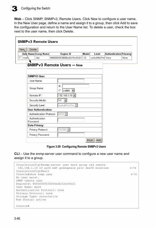
Configuring the Switch3
Web – Click SNMP, SNMPv3, Remote Users. Click New to configure a user name. In the New User page, define a name and assign it to a group, then click Add to save the configuration and return to the User Name list. To delete a user, check the box next to the user name, then click Delete.Figure 3-29 Configuring Remote SNMPv3 Users
CLI – Use the snmp-server user command to configure a new user name and assign it to a group.
Console(config)#snmp-server user mark group r&d remote 192.168.1.19 v3 auth md5 greenpeace priv des56 einstien 4-74Console(config)#exitConsole#show snmp user 4-74No user exist.SNMP remote userEngineId: 80000000030004e2b316c54321User Name: markAuthentication Protocol: nonePrivacy Protocol: noneStorage Type: nonvolatileRow Status: active
Console#
3-46
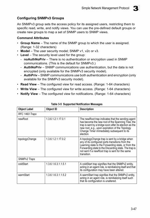
Simple Network Management Protocol 3
Configuring SNMPv3 GroupsAn SNMPv3 group sets the access policy for its assigned users, restricting them to specific read, write, and notify views. You can use the pre-defined default groups or create new groups to map a set of SNMP users to SNMP views.
Command Attributes
• Group Name – The name of the SNMP group to which the user is assigned. (Range: 1-32 characters)
• Model – The user security model; SNMP v1, v2c or v3.• Level – The security level used for the group:
- noAuthNoPriv – There is no authentication or encryption used in SNMP communications. (This is the default for SNMPv3.)
- AuthNoPriv – SNMP communications use authentication, but the data is not encrypted (only available for the SNMPv3 security model).
- AuthPriv – SNMP communications use both authentication and encryption (only available for the SNMPv3 security model).
• Read View – The configured view for read access. (Range: 1-64 characters)
• Write View – The configured view for write access. (Range: 1-64 characters)
• Notify View – The configured view for notifications. (Range: 1-64 characters)
Table 3-5 Supported Notification Messages
Object Label Object ID Description
RFC 1493 Traps
newRoot 1.3.6.1.2.1.17.0.1 The newRoot trap indicates that the sending agent has become the new root of the Spanning Tree; the trap is sent by a bridge soon after its election as the new root, e.g., upon expiration of the Topology Change Timer immediately subsequent to its election.
topologyChange 1.3.6.1.2.1.17.0.2 A topologyChange trap is sent by a bridge when any of its configured ports transitions from the Learning state to the Forwarding state, or from the Forwarding state to the Discarding state. The trap is not sent if a newRoot trap is sent for the same transition.
SNMPv2 Traps
coldStart 1.3.6.1.6.3.1.1.5.1 A coldStart trap signifies that the SNMPv2 entity, acting in an agent role, is reinitializing itself and that its configuration may have been altered.
warmStart 1.3.6.1.6.3.1.1.5.2 A warmStart trap signifies that the SNMPv2 entity, acting in an agent role, is reinitializing itself such that its configuration is unaltered.
3-47
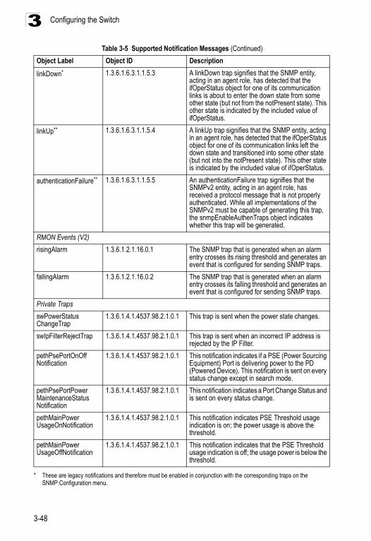
Configuring the Switch3
linkDown* 1.3.6.1.6.3.1.1.5.3 A linkDown trap signifies that the SNMP entity, acting in an agent role, has detected that the ifOperStatus object for one of its communication links is about to enter the down state from some other state (but not from the notPresent state). This other state is indicated by the included value of ifOperStatus.
linkUp** 1.3.6.1.6.3.1.1.5.4 A linkUp trap signifies that the SNMP entity, acting in an agent role, has detected that the ifOperStatus object for one of its communication links left the down state and transitioned into some other state (but not into the notPresent state). This other state is indicated by the included value of ifOperStatus.
authenticationFailure** 1.3.6.1.6.3.1.1.5.5 An authenticationFailure trap signifies that the SNMPv2 entity, acting in an agent role, has received a protocol message that is not properly authenticated. While all implementations of the SNMPv2 must be capable of generating this trap, the snmpEnableAuthenTraps object indicates whether this trap will be generated.
RMON Events (V2)
risingAlarm 1.3.6.1.2.1.16.0.1 The SNMP trap that is generated when an alarm entry crosses its rising threshold and generates an event that is configured for sending SNMP traps.
fallingAlarm 1.3.6.1.2.1.16.0.2 The SNMP trap that is generated when an alarm entry crosses its falling threshold and generates an event that is configured for sending SNMP traps.
Private Traps
swPowerStatus ChangeTrap
1.3.6.1.4.1.4537.98.2.1.0.1 This trap is sent when the power state changes.
swIpFilterRejectTrap 1.3.6.1.4.1.4537.98.2.1.0.1 This trap is sent when an incorrect IP address is rejected by the IP Filter.
pethPsePortOnOff Notification
1.3.6.1.4.1.4537.98.2.1.0.1 This notification indicates if a PSE (Power Sourcing Equipment) Port is delivering power to the PD (Powered Device). This notification is sent on every status change except in search mode.
pethPsePortPower MaintenanceStatus Notification
1.3.6.1.4.1.4537.98.2.1.0.1 This notification indicates a Port Change Status and is sent on every status change.
pethMainPower UsageOnNotification
1.3.6.1.4.1.4537.98.2.1.0.1 This notification indicates PSE Threshold usage indication is on; the power usage is above the threshold.
pethMainPower UsageOffNotification
1.3.6.1.4.1.4537.98.2.1.0.1 This notification indicates that the PSE Threshold usage indication is off; the usage power is below the threshold.
* These are legacy notifications and therefore must be enabled in conjunction with the corresponding traps on the SNMP Configuration menu.
Table 3-5 Supported Notification Messages (Continued)
Object Label Object ID Description
3-48
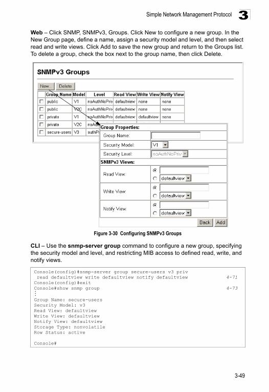
Simple Network Management Protocol 3
Web – Click SNMP, SNMPv3, Groups. Click New to configure a new group. In the New Group page, define a name, assign a security model and level, and then select read and write views. Click Add to save the new group and return to the Groups list. To delete a group, check the box next to the group name, then click Delete.Figure 3-30 Configuring SNMPv3 Groups
CLI – Use the snmp-server group command to configure a new group, specifying the security model and level, and restricting MIB access to defined read, write, and notify views.
Console(config)#snmp-server group secure-users v3 priv read defaultview write defaultview notify defaultview 4-71Console(config)#exitConsole#show snmp group 4-73...Group Name: secure-usersSecurity Model: v3Read View: defaultviewWrite View: defaultviewNotify View: defaultviewStorage Type: nonvolatileRow Status: active
Console#
3-49
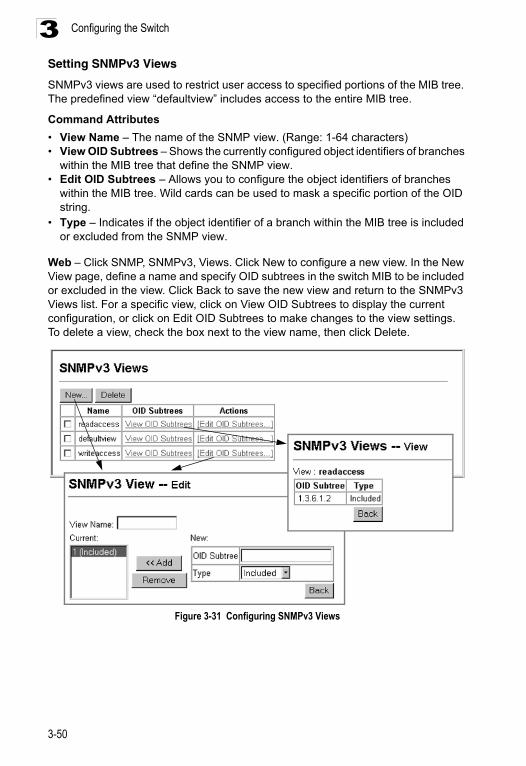
Configuring the Switch3
Setting SNMPv3 ViewsSNMPv3 views are used to restrict user access to specified portions of the MIB tree. The predefined view “defaultview” includes access to the entire MIB tree.
Command Attributes
• View Name – The name of the SNMP view. (Range: 1-64 characters)• View OID Subtrees – Shows the currently configured object identifiers of branches
within the MIB tree that define the SNMP view.• Edit OID Subtrees – Allows you to configure the object identifiers of branches
within the MIB tree. Wild cards can be used to mask a specific portion of the OID string.
• Type – Indicates if the object identifier of a branch within the MIB tree is included or excluded from the SNMP view.
Web – Click SNMP, SNMPv3, Views. Click New to configure a new view. In the New View page, define a name and specify OID subtrees in the switch MIB to be included or excluded in the view. Click Back to save the new view and return to the SNMPv3 Views list. For a specific view, click on View OID Subtrees to display the current configuration, or click on Edit OID Subtrees to make changes to the view settings. To delete a view, check the box next to the view name, then click Delete.
Figure 3-31 Configuring SNMPv3 Views
3-50
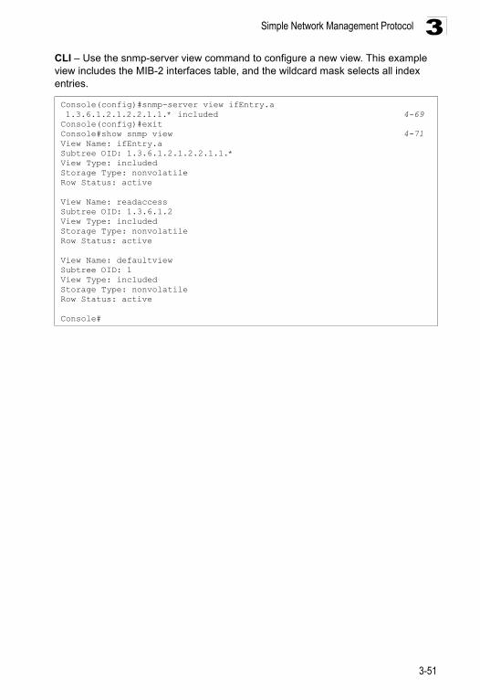
Simple Network Management Protocol 3
CLI – Use the snmp-server view command to configure a new view. This example view includes the MIB-2 interfaces table, and the wildcard mask selects all index entries.Console(config)#snmp-server view ifEntry.a 1.3.6.1.2.1.2.2.1.1.* included 4-69Console(config)#exitConsole#show snmp view 4-71View Name: ifEntry.aSubtree OID: 1.3.6.1.2.1.2.2.1.1.*View Type: includedStorage Type: nonvolatileRow Status: active
View Name: readaccessSubtree OID: 1.3.6.1.2View Type: includedStorage Type: nonvolatileRow Status: active
View Name: defaultviewSubtree OID: 1View Type: includedStorage Type: nonvolatileRow Status: active
Console#
3-51
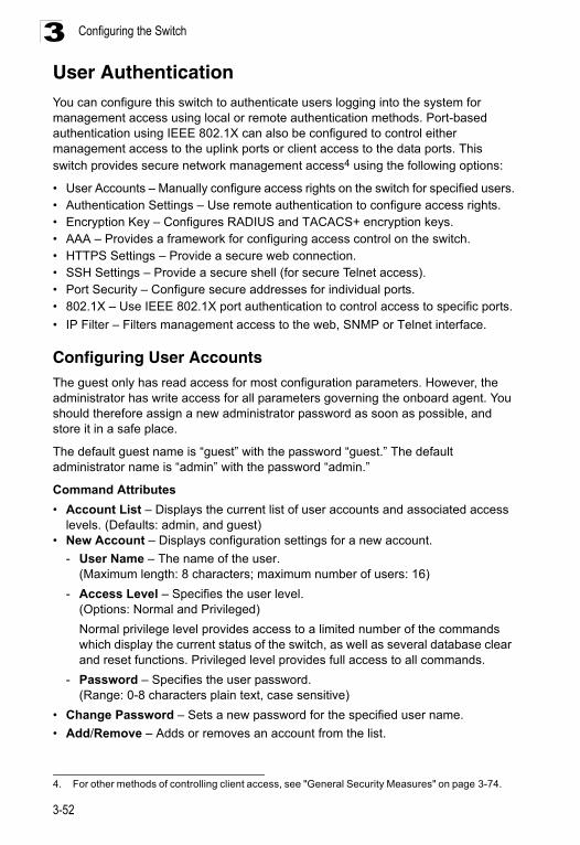
Configuring the Switch3
User AuthenticationYou can configure this switch to authenticate users logging into the system for management access using local or remote authentication methods. Port-based authentication using IEEE 802.1X can also be configured to control either management access to the uplink ports or client access to the data ports. This switch provides secure network management access4 using the following options:• User Accounts – Manually configure access rights on the switch for specified users.• Authentication Settings – Use remote authentication to configure access rights.• Encryption Key – Configures RADIUS and TACACS+ encryption keys.• AAA – Provides a framework for configuring access control on the switch.• HTTPS Settings – Provide a secure web connection.• SSH Settings – Provide a secure shell (for secure Telnet access).• Port Security – Configure secure addresses for individual ports.• 802.1X – Use IEEE 802.1X port authentication to control access to specific ports.
• IP Filter – Filters management access to the web, SNMP or Telnet interface.
Configuring User AccountsThe guest only has read access for most configuration parameters. However, the administrator has write access for all parameters governing the onboard agent. You should therefore assign a new administrator password as soon as possible, and store it in a safe place.
The default guest name is “guest” with the password “guest.” The default administrator name is “admin” with the password “admin.”
Command Attributes
• Account List – Displays the current list of user accounts and associated access levels. (Defaults: admin, and guest)
• New Account – Displays configuration settings for a new account.
- User Name – The name of the user. (Maximum length: 8 characters; maximum number of users: 16)
- Access Level – Specifies the user level.(Options: Normal and Privileged)
Normal privilege level provides access to a limited number of the commands which display the current status of the switch, as well as several database clear and reset functions. Privileged level provides full access to all commands.
- Password – Specifies the user password.(Range: 0-8 characters plain text, case sensitive)
• Change Password – Sets a new password for the specified user name.
• Add/Remove – Adds or removes an account from the list.
4. For other methods of controlling client access, see "General Security Measures" on page 3-74.
3-52
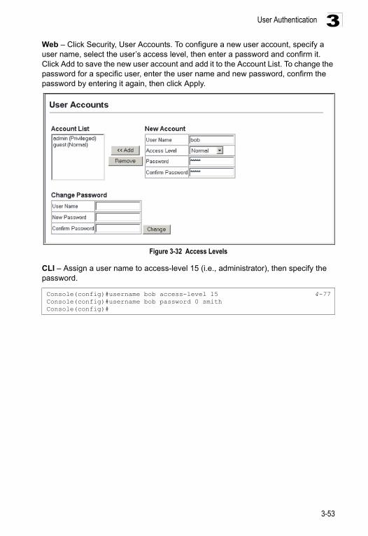
User Authentication 3
Web – Click Security, User Accounts. To configure a new user account, specify a user name, select the user’s access level, then enter a password and confirm it. Click Add to save the new user account and add it to the Account List. To change the password for a specific user, enter the user name and new password, confirm the password by entering it again, then click Apply.Figure 3-32 Access Levels
CLI – Assign a user name to access-level 15 (i.e., administrator), then specify the password.
Console(config)#username bob access-level 15 4-77Console(config)#username bob password 0 smithConsole(config)#
3-53
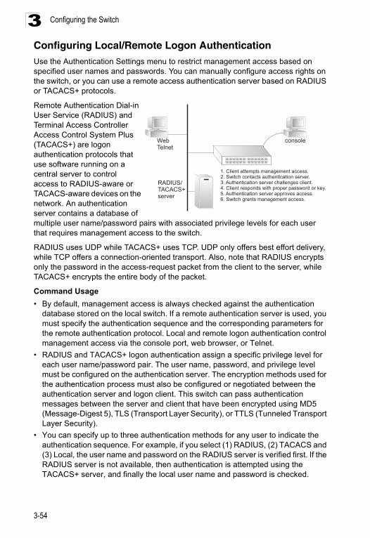
Configuring the Switch3
Configuring Local/Remote Logon AuthenticationUse the Authentication Settings menu to restrict management access based on specified user names and passwords. You can manually configure access rights on the switch, or you can use a remote access authentication server based on RADIUS or TACACS+ protocols.Remote Authentication Dial-in User Service (RADIUS) and Terminal Access Controller Access Control System Plus (TACACS+) are logon authentication protocols that use software running on a central server to control access to RADIUS-aware or TACACS-aware devices on the network. An authentication server contains a database of multiple user name/password pairs with associated privilege levels for each user that requires management access to the switch.
RADIUS uses UDP while TACACS+ uses TCP. UDP only offers best effort delivery, while TCP offers a connection-oriented transport. Also, note that RADIUS encrypts only the password in the access-request packet from the client to the server, while TACACS+ encrypts the entire body of the packet.
Command Usage
• By default, management access is always checked against the authentication database stored on the local switch. If a remote authentication server is used, you must specify the authentication sequence and the corresponding parameters for the remote authentication protocol. Local and remote logon authentication control management access via the console port, web browser, or Telnet.
• RADIUS and TACACS+ logon authentication assign a specific privilege level for each user name/password pair. The user name, password, and privilege level must be configured on the authentication server. The encryption methods used for the authentication process must also be configured or negotiated between the authentication server and logon client. This switch can pass authentication messages between the server and client that have been encrypted using MD5 (Message-Digest 5), TLS (Transport Layer Security), or TTLS (Tunneled Transport Layer Security).
• You can specify up to three authentication methods for any user to indicate the authentication sequence. For example, if you select (1) RADIUS, (2) TACACS and (3) Local, the user name and password on the RADIUS server is verified first. If the RADIUS server is not available, then authentication is attempted using the TACACS+ server, and finally the local user name and password is checked.
WebTelnet
RADIUS/TACACS+server
console
1. Client attempts management access.2. Switch contacts authentication server.3. Authentication server challenges client.4. Client responds with proper password or key.5. Authentication server approves access.6. Switch grants management access.
3-54
User Authentication 3
Command Attributes• Authentication – Select the authentication, or authentication sequence required:
- Local – User authentication is performed only locally by the switch.- Radius – User authentication is performed using a RADIUS server only.- TACACS – User authentication is performed using a TACACS+ server only.- [authentication sequence] – User authentication is performed by up to three
authentication methods in the indicated sequence.• RADIUS Settings
- Global – Provides globally applicable RADIUS settings.
- Server Index – Specifies one of five RADIUS servers that may be configured. The switch attempts authentication using the listed sequence of servers. The process ends when a server either approves or denies access to a user.
- Server IP Address5 – Address of authentication server.
- Server Port Number – Network (UDP) port of authentication server used for authentication messages. (Range: 1-65535; Default: 1812)
- Secret Text String – Encryption key used to authenticate logon access for client. Do not use blank spaces in the string. (Maximum length: 48 characters)
- Number of Server Transmits – Number of times the switch tries to authenticate logon access via the authentication server. (Range: 1-30; Default: 2)
- Timeout for a Reply – The number of seconds the switch waits for a reply from the RADIUS server before it resends the request. (Range: 1-65535; Default: 5)
• TACACS Settings
- Global – Provides globally applicable TACACS+ settings.
- Server Index – Specifies the index number of the server to be configured. The switch currently supports only one TACACS+ server.
- Server IP Address5 – Address of the TACACS+ server.
- Server Port Number – Network (TCP) port of TACACS+ server used for authentication messages. (Range: 1-65535; Default: 49)
- Number of Server Transmits – Number of times the switch tries to authenticate logon access via the authentication server. (Range: 1-30; Default: 2)
- Secret Text String – Encryption key used to authenticate logon access for client. Do not use blank spaces in the string. (Maximum length: 48 characters)
- Timeout for a Reply – The number of seconds the switch waits for a reply from the RADIUS server before it resends the request. (Range: 1-540; Default: 5)
Note: The local switch user database has to be set up by manually entering user names and passwords using the CLI. (See "username" on page 4-77)
5. A Server Index must be selected to display this item.
3-55
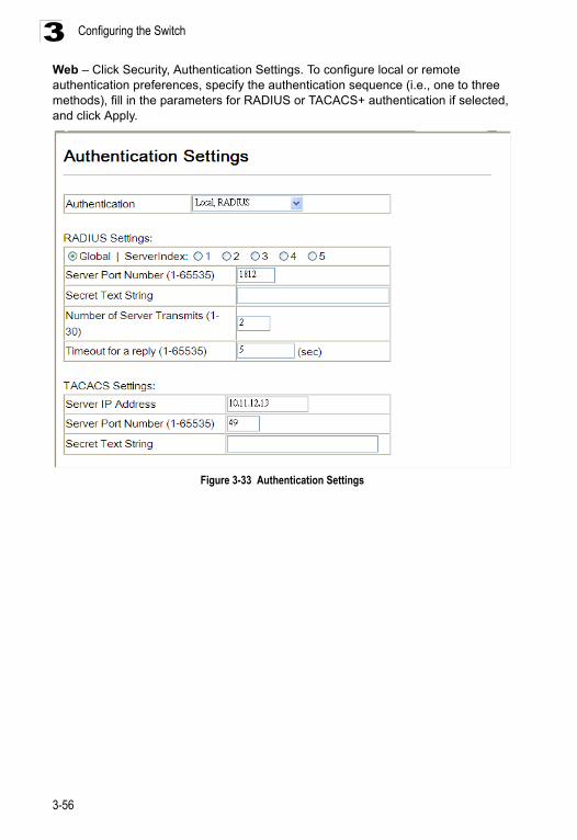
Configuring the Switch3
Web – Click Security, Authentication Settings. To configure local or remote authentication preferences, specify the authentication sequence (i.e., one to three methods), fill in the parameters for RADIUS or TACACS+ authentication if selected, and click Apply.Figure 3-33 Authentication Settings
3-56
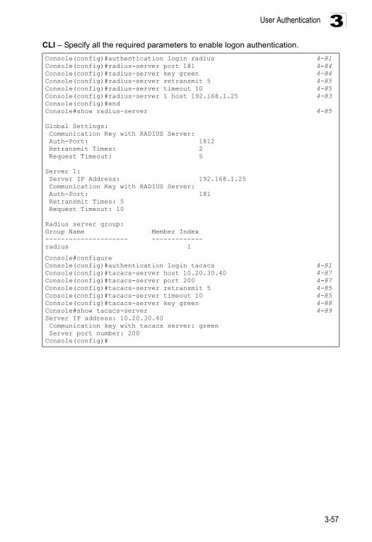
User Authentication 3
CLI – Specify all the required parameters to enable logon authentication.Console(config)#authentication login radius 4-81Console(config)#radius-server port 181 4-84Console(config)#radius-server key green 4-84Console(config)#radius-server retransmit 5 4-85Console(config)#radius-server timeout 10 4-85Console(config)#radius-server 1 host 192.168.1.25 4-83Console(config)#endConsole#show radius-server 4-85
Global Settings: Communication Key with RADIUS Server: Auth-Port: 1812 Retransmit Times: 2 Request Timeout: 5
Server 1: Server IP Address: 192.168.1.25 Communication Key with RADIUS Server: Auth-Port: 181 Retransmit Times: 5 Request Timeout: 10
Radius server group:Group Name Member Index--------------------- -------------radius 1
Console#configureConsole(config)#authentication login tacacs 4-81Console(config)#tacacs-server host 10.20.30.40 4-87Console(config)#tacacs-server port 200 4-87Console(config)#tacacs-server retransmit 5 4-85Console(config)#tacacs-server timeout 10 4-85Console(config)#tacacs-server key green 4-88Console#show tacacs-server 4-89Server IP address: 10.20.30.40 Communication key with tacacs server: green Server port number: 200Console(config)#
3-57
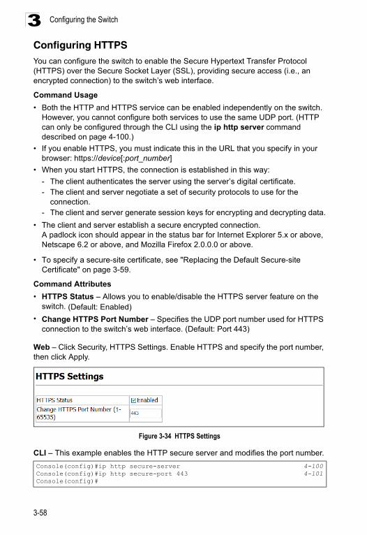
Configuring the Switch3
Configuring HTTPSYou can configure the switch to enable the Secure Hypertext Transfer Protocol (HTTPS) over the Secure Socket Layer (SSL), providing secure access (i.e., an encrypted connection) to the switch’s web interface.Command Usage
• Both the HTTP and HTTPS service can be enabled independently on the switch. However, you cannot configure both services to use the same UDP port. (HTTP can only be configured through the CLI using the ip http server command described on page 4-100.)
• If you enable HTTPS, you must indicate this in the URL that you specify in your browser: https://device[:port_number]
• When you start HTTPS, the connection is established in this way:
- The client authenticates the server using the server’s digital certificate.- The client and server negotiate a set of security protocols to use for the
connection.- The client and server generate session keys for encrypting and decrypting data.
• The client and server establish a secure encrypted connection.A padlock icon should appear in the status bar for Internet Explorer 5.x or above, Netscape 6.2 or above, and Mozilla Firefox 2.0.0.0 or above.
• To specify a secure-site certificate, see "Replacing the Default Secure-site Certificate" on page 3-59.
Command Attributes
• HTTPS Status – Allows you to enable/disable the HTTPS server feature on the switch. (Default: Enabled)
• Change HTTPS Port Number – Specifies the UDP port number used for HTTPS connection to the switch’s web interface. (Default: Port 443)
Web – Click Security, HTTPS Settings. Enable HTTPS and specify the port number, then click Apply.
Figure 3-34 HTTPS Settings
CLI – This example enables the HTTP secure server and modifies the port number.
Console(config)#ip http secure-server 4-100Console(config)#ip http secure-port 443 4-101Console(config)#
3-58
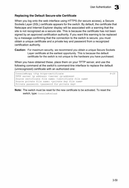
User Authentication 3
Replacing the Default Secure-site CertificateWhen you log onto the web interface using HTTPS (for secure access), a Secure Sockets Layer (SSL) certificate appears for the switch. By default, the certificate that Netscape and Internet Explorer display will be associated with a warning that the site is not recognized as a secure site. This is because the certificate has not been signed by an approved certification authority. If you want this warning to be replaced by a message confirming that the connection to the switch is secure, you must obtain a unique certificate and a private key and password from a recognized certification authority.
Caution: For maximum security, we recommend you obtain a unique Secure Sockets Layer certificate at the earliest opportunity. This is because the default certificate for the switch is not unique to the hardware you have purchased.
When you have obtained these, place them on your TFTP server, and use the following command at the switch's command-line interface to replace the default (unrecognized) certificate with an authorized one:
Note: The switch must be reset for the new certificate to be activated. To reset the switch, type: Console#reload
Console#copy tftp https-certificate 4-25TFTP server ip address: <server ip-address>Source certificate file name: <certificate file name>Source private file name: <private key file name>Private password: <password for private key>
3-59
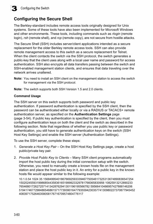
Configuring the Switch3
Configuring the Secure Shell The Berkley-standard includes remote access tools originally designed for Unix systems. Some of these tools have also been implemented for Microsoft Windows and other environments. These tools, including commands such as rlogin (remote login), rsh (remote shell), and rcp (remote copy), are not secure from hostile attacks.The Secure Shell (SSH) includes server/client applications intended as a secure replacement for the older Berkley remote access tools. SSH can also provide remote management access to this switch as a secure replacement for Telnet. When the client contacts the switch via the SSH protocol, the switch generates a public-key that the client uses along with a local user name and password for access authentication. SSH also encrypts all data transfers passing between the switch and SSH-enabled management station clients, and ensures that data traveling over the network arrives unaltered.
Note: You need to install an SSH client on the management station to access the switch for management via the SSH protocol.
Note: The switch supports both SSH Version 1.5 and 2.0 clients.
Command Usage
The SSH server on this switch supports both password and public key authentication. If password authentication is specified by the SSH client, then the password can be authenticated either locally or via a RADIUS or TACACS+ remote authentication server, as specified on the Authentication Settings page (page 3-54). If public key authentication is specified by the client, then you must configure authentication keys on both the client and the switch as described in the following section. Note that regardless of whether you use public key or password authentication, you still have to generate authentication keys on the switch (SSH Host Key Settings) and enable the SSH server (Authentication Settings).
To use the SSH server, complete these steps:
1. Generate a Host Key Pair – On the SSH Host Key Settings page, create a host public/private key pair.
2. Provide Host Public Key to Clients – Many SSH client programs automatically import the host public key during the initial connection setup with the switch. Otherwise, you need to manually create a known hosts file on the management station and place the host public key in it. An entry for a public key in the known hosts file would appear similar to the following example:
10.1.0.54 1024 35 15684995401867669259333946775054617325313674890836547254 15020245593199868544358361651999923329781766065830956 10825913212890233 76546801726272571413428762941301196195566782 59566410486957427888146206 5194174677298486546861571773939016477935594230357741309802273708779454524083971752646358058176716709574804776117
3-60
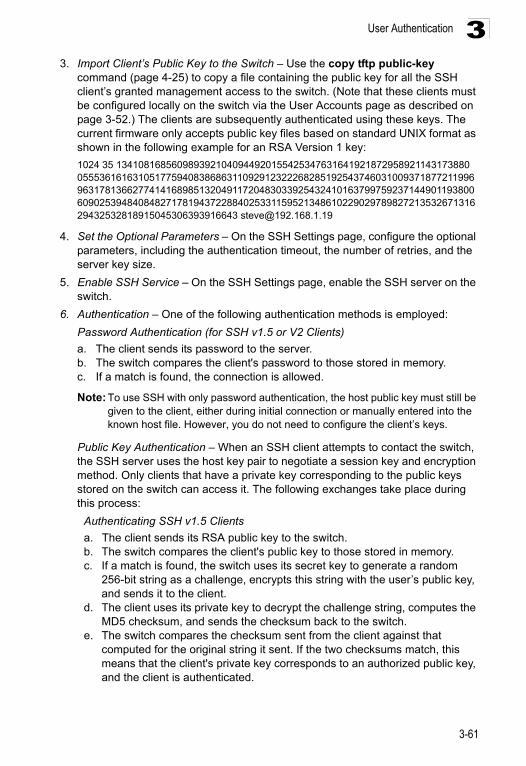
User Authentication 3
3. Import Client’s Public Key to the Switch – Use the copy tftp public-keycommand (page 4-25) to copy a file containing the public key for all the SSH client’s granted management access to the switch. (Note that these clients must be configured locally on the switch via the User Accounts page as described on page 3-52.) The clients are subsequently authenticated using these keys. The current firmware only accepts public key files based on standard UNIX format as shown in the following example for an RSA Version 1 key:
1024 35 1341081685609893921040944920155425347631641921872958921143173880 05553616163105177594083868631109291232226828519254374603100937187721199696317813662774141689851320491172048303392543241016379975923714490119380060902539484084827178194372288402533115952134861022902978982721353267131629432532818915045306393916643 [email protected]
4. Set the Optional Parameters – On the SSH Settings page, configure the optional parameters, including the authentication timeout, the number of retries, and the server key size.
5. Enable SSH Service – On the SSH Settings page, enable the SSH server on the switch.
6. Authentication – One of the following authentication methods is employed:
Password Authentication (for SSH v1.5 or V2 Clients)
a. The client sends its password to the server.b. The switch compares the client's password to those stored in memory. c. If a match is found, the connection is allowed.
Note: To use SSH with only password authentication, the host public key must still be given to the client, either during initial connection or manually entered into the known host file. However, you do not need to configure the client’s keys.
Public Key Authentication – When an SSH client attempts to contact the switch, the SSH server uses the host key pair to negotiate a session key and encryption method. Only clients that have a private key corresponding to the public keys stored on the switch can access it. The following exchanges take place during this process:
Authenticating SSH v1.5 Clients
a. The client sends its RSA public key to the switch.b. The switch compares the client's public key to those stored in memory.c. If a match is found, the switch uses its secret key to generate a random
256-bit string as a challenge, encrypts this string with the user’s public key, and sends it to the client.
d. The client uses its private key to decrypt the challenge string, computes the MD5 checksum, and sends the checksum back to the switch.
e. The switch compares the checksum sent from the client against that computed for the original string it sent. If the two checksums match, this means that the client's private key corresponds to an authorized public key, and the client is authenticated.
3-61
Configuring the Switch3
Authenticating SSH v2 Clientsa. The client first queries the switch to determine if DSA public key authentication using a preferred algorithm is acceptable.
b. If the specified algorithm is supported by the switch, it notifies the client to proceed with the authentication process. Otherwise, it rejects the request.
c. The client sends a signature generated using the private key to the switch.d. When the server receives this message, it checks whether the supplied key
is acceptable for authentication, and if so, it then checks whether the signature is correct. If both checks succeed, the client is authenticated.
Note: The SSH server supports up to four client sessions. The maximum number of client sessions includes both current Telnet sessions and SSH sessions.
Generating the Host Key Pair
A host public/private key pair is used to provide secure communications between an SSH client and the switch. After generating this key pair, you must provide the host public key to SSH clients and import the client’s public key to the switch as described in the proceeding section (Command Usage).
Field Attributes
• Public-Key of Host-Key – The public key for the host.
• RSA (Version 1): The first field indicates the size of the host key (e.g., 1024), the second field is the encoded public exponent (e.g., 65537), and the last string is the encoded modulus.
• DSA (Version 2): The first field indicates that the encryption method used by SSH is based on the Digital Signature Standard (DSS). The last string is the encoded modulus.
• Host-Key Type – The key type used to generate the host key pair (i.e., public and private keys). (Range: RSA (Version 1), DSA (Version 2), Both: Default: Both)The SSH server uses RSA or DSA for key exchange when the client first establishes a connection with the switch, and then negotiates with the client to select either DES (56-bit) or 3DES (168-bit) for data encryption.
Note: The switch uses only RSA Version 1 for SSHv1.5 clients and DSA Version 2 for SSHv2 clients.
• Save Host-Key from Memory to Flash – Saves the host key from RAM (i.e., volatile memory to flash memory. Otherwise, the host key pair is stored to RAM by default. Note that you must select this item prior to generating the host-key pair.
• Generate – This button is used to generate the host key pair. Note that you must first generate the host key pair before you can enable the SSH server on the SSH Server Settings page.
• Clear – This button clears the host key from both volatile memory (RAM) and non-volatile memory (Flash).
3-62
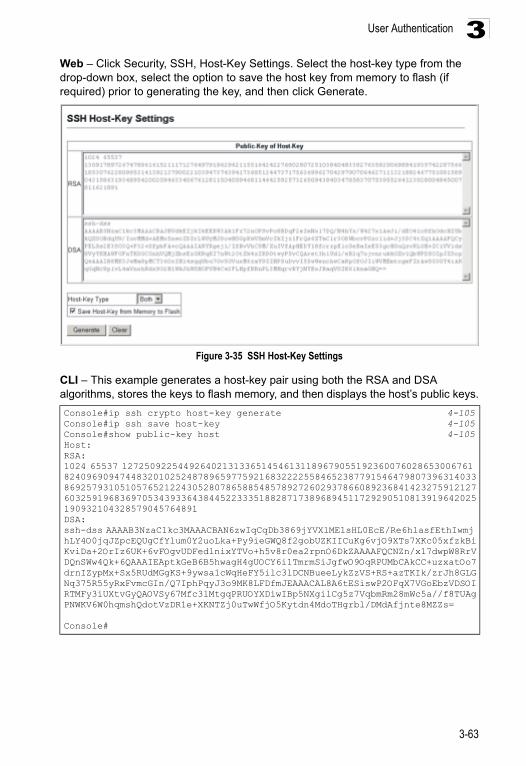
User Authentication 3
Web – Click Security, SSH, Host-Key Settings. Select the host-key type from the drop-down box, select the option to save the host key from memory to flash (if required) prior to generating the key, and then click Generate.Figure 3-35 SSH Host-Key Settings
CLI – This example generates a host-key pair using both the RSA and DSA algorithms, stores the keys to flash memory, and then displays the host’s public keys.
Console#ip ssh crypto host-key generate 4-105Console#ip ssh save host-key 4-105Console#show public-key host 4-105Host:RSA:1024 65537 127250922544926402131336514546131189679055192360076028653006761 824096909474483201025248789659775921683222255846523877915464798073963140338692579310510576521224305280786588548578927260293786608923684142327591212760325919683697053439336438445223335188287173896894511729290510813919642025190932104328579045764891DSA:ssh-dss AAAAB3NzaC1kc3MAAACBAN6zwIqCqDb3869jYVXlME1sHL0EcE/Re6hlasfEthIwmj hLY4O0jqJZpcEQUgCfYlum0Y2uoLka+Py9ieGWQ8f2gobUZKIICuKg6vjO9XTs7XKc05xfzkBiKviDa+2OrIz6UK+6vFOgvUDFedlnixYTVo+h5v8r0ea2rpnO6DkZAAAAFQCNZn/x17dwpW8RrV DQnSWw4Qk+6QAAAIEAptkGeB6B5hwagH4gUOCY6i1TmrmSiJgfwO9OqRPUMbCAkCC+uzxatOo7drnIZypMx+Sx5RUdMGgKS+9ywsa1cWqHeFY5ilc3lDCNBueeLykZzVS+RS+azTKIk/zrJh8GLG Nq375R55yRxFvmcGIn/Q7IphPqyJ3o9MK8LFDfmJEAAACAL8A6tESiswP2OFqX7VGoEbzVDSOI RTMFy3iUXtvGyQAOVSy67Mfc3lMtgqPRUOYXDiwIBp5NXgilCg5z7VqbmRm28mWc5a//f8TUAg PNWKV6W0hqmshQdotVzDR1e+XKNTZj0uTwWfjO5Kytdn4MdoTHgrbl/DMdAfjnte8MZZs=
Console#
3-63
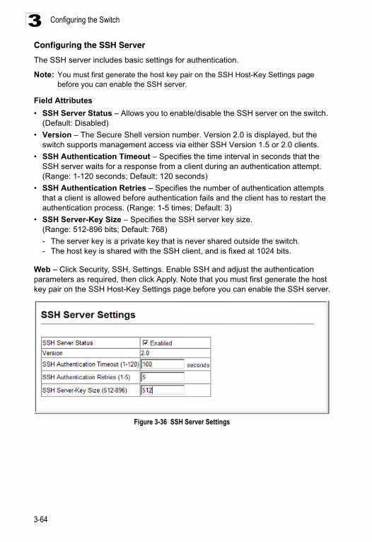
Configuring the Switch3
Configuring the SSH ServerThe SSH server includes basic settings for authentication.
Note: You must first generate the host key pair on the SSH Host-Key Settings page before you can enable the SSH server.
Field Attributes
• SSH Server Status – Allows you to enable/disable the SSH server on the switch. (Default: Disabled)
• Version – The Secure Shell version number. Version 2.0 is displayed, but the switch supports management access via either SSH Version 1.5 or 2.0 clients.
• SSH Authentication Timeout – Specifies the time interval in seconds that the SSH server waits for a response from a client during an authentication attempt.(Range: 1-120 seconds; Default: 120 seconds)
• SSH Authentication Retries – Specifies the number of authentication attempts that a client is allowed before authentication fails and the client has to restart the authentication process. (Range: 1-5 times; Default: 3)
• SSH Server-Key Size – Specifies the SSH server key size. (Range: 512-896 bits; Default: 768)
- The server key is a private key that is never shared outside the switch.- The host key is shared with the SSH client, and is fixed at 1024 bits.
Web – Click Security, SSH, Settings. Enable SSH and adjust the authentication parameters as required, then click Apply. Note that you must first generate the host key pair on the SSH Host-Key Settings page before you can enable the SSH server.
Figure 3-36 SSH Server Settings
3-64
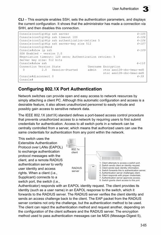
User Authentication 3
CLI – This example enables SSH, sets the authentication parameters, and displays the current configuration. It shows that the administrator has made a connection via SHH, and then disables this connection.Configuring 802.1X Port Authentication Network switches can provide open and easy access to network resources by simply attaching a client PC. Although this automatic configuration and access is a desirable feature, it also allows unauthorized personnel to easily intrude and possibly gain access to sensitive network data.
The IEEE 802.1X (dot1X) standard defines a port-based access control procedure that prevents unauthorized access to a network by requiring users to first submit credentials for authentication. Access to all switch ports in a network can be centrally controlled from a server, which means that authorized users can use the same credentials for authentication from any point within the network.
This switch uses the Extensible Authentication Protocol over LANs (EAPOL) to exchange authentication protocol messages with the client, and a remote RADIUS authentication server to verify user identity and access rights. When a client (i.e., Supplicant) connects to a switch port, the switch (i.e., Authenticator) responds with an EAPOL identity request. The client provides its identity (such as a user name) in an EAPOL response to the switch, which it forwards to the RADIUS server. The RADIUS server verifies the client identity and sends an access challenge back to the client. The EAP packet from the RADIUS server contains not only the challenge, but the authentication method to be used. The client can reject the authentication method and request another, depending on the configuration of the client software and the RADIUS server. The encryption method used to pass authentication messages can be MD5 (Message-Digest 5),
Console(config)#ip ssh server 4-105Console(config)#ip ssh timeout 100 4-106Console(config)#ip ssh authentication-retries 5 4-106Console(config)#ip ssh server-key size 512 4-107Console(config)#endConsole#show ip ssh 4-109SSH Enabled - version 2.0Negotiation timeout: 120 secs; Authentication retries: 5Server key size: 512 bitsConsole#show ssh 4-110Connection Version State Username Encryption 0 2.0 Session-Started admin ctos aes128-cbc-hmac-md5 stoc aes128-cbc-hmac-md5Console#disconnect 0 4-39Console#
802.1xclient
RADIUSserver
1. Client attempts to access a switch port.2. Switch sends client an identity request.3. Client sends back identity information.4. Switch forwards this to authentication server.5. Authentication server challenges client.6. Client responds with proper credentials.7. Authentication server approves access.8. Switch grants client access to this port.
3-65
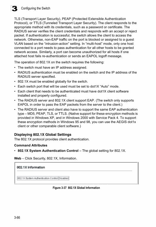
Configuring the Switch3
TLS (Transport Layer Security), PEAP (Protected Extensible Authentication Protocol), or TTLS (Tunneled Transport Layer Security). The client responds to the appropriate method with its credentials, such as a password or certificate. The RADIUS server verifies the client credentials and responds with an accept or reject packet. If authentication is successful, the switch allows the client to access the network. Otherwise, non-EAP traffic on the port is blocked or assigned to a guest VLAN based on the “intrusion-action” setting. In “multi-host” mode, only one host connected to a port needs to pass authentication for all other hosts to be granted network access. Similarly, a port can become unauthorized for all hosts if one attached host fails re-authentication or sends an EAPOL logoff message.The operation of 802.1X on the switch requires the following:
• The switch must have an IP address assigned.
• RADIUS authentication must be enabled on the switch and the IP address of the RADIUS server specified.
• 802.1X must be enabled globally for the switch.
• Each switch port that will be used must be set to dot1X “Auto” mode.
• Each client that needs to be authenticated must have dot1X client software installed and properly configured.
• The RADIUS server and 802.1X client support EAP. (The switch only supports EAPOL in order to pass the EAP packets from the server to the client.)
• The RADIUS server and client also have to support the same EAP authentication type – MD5, PEAP, TLS, or TTLS. (Native support for these encryption methods is provided in Windows XP, and in Windows 2000 with Service Pack 4. To support these encryption methods in Windows 95 and 98, you can use the AEGIS dot1x client or other comparable client software.)
Displaying 802.1X Global SettingsThe 802.1X protocol provides client authentication.
Command Attributes
• 802.1X System Authentication Control – The global setting for 802.1X.
Web – Click Security, 802.1X, Information.
Figure 3-37 802.1X Global Information
3-66
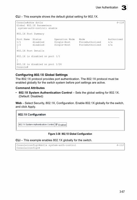
User Authentication 3
CLI – This example shows the default global setting for 802.1X.Configuring 802.1X Global SettingsThe 802.1X protocol provides port authentication. The 802.1X protocol must be enabled globally for the switch system before port settings are active.
Command Attributes
• 802.1X System Authentication Control – Sets the global setting for 802.1X. (Default: Disabled)
Web – Select Security, 802.1X, Configuration. Enable 802.1X globally for the switch, and click Apply.
Figure 3-38 802.1X Global Configuration
CLI – This example enables 802.1X globally for the switch.
Console#show dot1x 4-118Global 802.1X Parameters system-auth-control: enable
802.1X Port Summary
Port Name Status Operation Mode Mode Authorized1/1 disabled Single-Host ForceAuthorized n/a1/2 disabled Single-Host ForceAuthorized n/a...802.1X Port Details
802.1X is disabled on port 1/1...802.1X is disabled on port 1/26Console#
Console(config)#dot1x system-auth-control 4-112Console(config)#
3-67
Configuring the Switch3
Configuring Port Settings for 802.1XWhen 802.1X is enabled, you need to configure the parameters for the authentication process that runs between the client and the switch (i.e., authenticator), as well as the client identity lookup process that runs between the switch and authentication server. These parameters are described in this section.
Command Attributes
• Port – Port number.
• Status – Indicates if authentication is enabled or disabled on the port. (Default: Disabled)
• Operation Mode – Allows single or multiple hosts (clients) to connect to an 802.1X-authorized port. (Options: Single-Host, Multi-Host; Default: Single-Host)
• Max Count – The maximum number of hosts that can connect to a port when the Multi-Host operation mode is selected. (Range: 1-1024; Default: 5)
• Mode – Sets the authentication mode to one of the following options:
- Auto – Requires a dot1x-aware client to be authorized by the authentication server. Clients that are not dot1x-aware will be denied access.
- Force-Authorized – Forces the port to grant access to all clients, either dot1x-aware or otherwise. (This is the default setting.)
- Force-Unauthorized – Forces the port to deny access to all clients, either dot1x-aware or otherwise.
• Re-authentication – Sets the client to be re-authenticated after the interval specified by the Re-authentication Period. Re-authentication can be used to detect if a new device is plugged into a switch port. (Default: Disabled)
• Max-Request – Sets the maximum number of times the switch port will retransmit an EAP request packet to the client before it times out the authentication session. (Range: 1-10; Default 2)
• Quiet Period – Sets the time that a switch port waits after the Max Request Count has been exceeded before attempting to acquire a new client. (Range: 1-65535 seconds; Default: 60 seconds)
• Re-authentication Period – Sets the time period after which a connected client must be re-authenticated. (Range: 1-65535 seconds; Default: 3600 seconds)
• Tx Period – Sets the time period during an authentication session that the switch waits before re-transmitting an EAP packet. (Range: 1-65535; Default: 30 seconds)
• Authorized –
- Yes – Connected client is authorized.- No – Connected client is not authorized.- Blank – Displays nothing when dot1x is disabled on a port.
• Supplicant – Indicates the MAC address of a connected client.
• Trunk – Indicates if the port is configured as a trunk port.
3-68
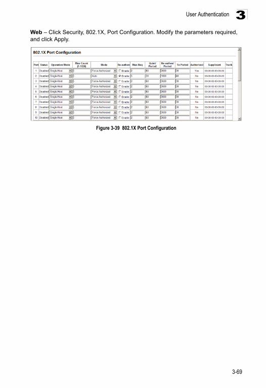
User Authentication 3
Web – Click Security, 802.1X, Port Configuration. Modify the parameters required, and click Apply.Figure 3-39 802.1X Port Configuration
3-69
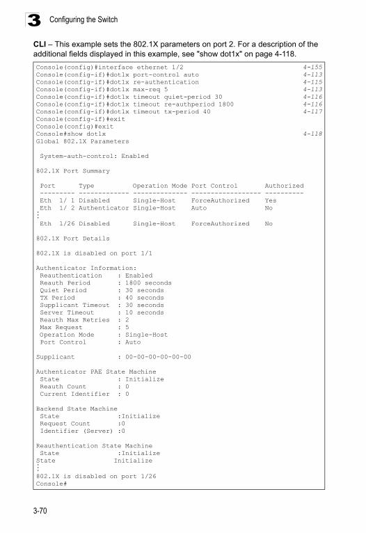
Configuring the Switch3
CLI – This example sets the 802.1X parameters on port 2. For a description of the additional fields displayed in this example, see "show dot1x" on page 4-118.Console(config)#interface ethernet 1/2 4-155Console(config-if)#dot1x port-control auto 4-113Console(config-if)#dot1x re-authentication 4-115 Console(config-if)#dot1x max-req 5 4-113Console(config-if)#dot1x timeout quiet-period 30 4-116Console(config-if)#dot1x timeout re-authperiod 1800 4-116Console(config-if)#dot1x timeout tx-period 40 4-117Console(config-if)#exitConsole(config)#exitConsole#show dot1x 4-118Global 802.1X Parameters
System-auth-control: Enabled
802.1X Port Summary
Port Type Operation Mode Port Control Authorized --------- ------------- -------------- ------------------ ---------- Eth 1/ 1 Disabled Single-Host ForceAuthorized Yes Eth 1/ 2 Authenticator Single-Host Auto No... Eth 1/26 Disabled Single-Host ForceAuthorized No
802.1X Port Details
802.1X is disabled on port 1/1
Authenticator Information: Reauthentication : Enabled Reauth Period : 1800 seconds Quiet Period : 30 seconds TX Period : 40 seconds Supplicant Timeout : 30 seconds Server Timeout : 10 seconds Reauth Max Retries : 2 Max Request : 5 Operation Mode : Single-Host Port Control : Auto
Supplicant : 00-00-00-00-00-00
Authenticator PAE State Machine State : Initialize Reauth Count : 0 Current Identifier : 0
Backend State Machine State :Initialize Request Count :0 Identifier (Server) :0
Reauthentication State Machine State :InitializeState Initialize...802.1X is disabled on port 1/26Console#
3-70
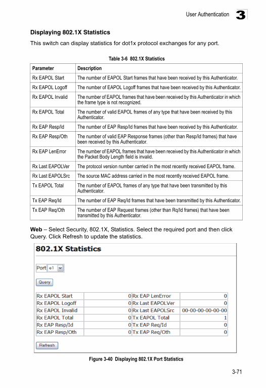
User Authentication 3
Displaying 802.1X StatisticsThis switch can display statistics for dot1x protocol exchanges for any port.
Web – Select Security, 802.1X, Statistics. Select the required port and then click Query. Click Refresh to update the statistics.
Figure 3-40 Displaying 802.1X Port Statistics
Table 3-6 802.1X Statistics
Parameter Description
Rx EAPOL Start The number of EAPOL Start frames that have been received by this Authenticator.
Rx EAPOL Logoff The number of EAPOL Logoff frames that have been received by this Authenticator.
Rx EAPOL Invalid The number of EAPOL frames that have been received by this Authenticator in which the frame type is not recognized.
Rx EAPOL Total The number of valid EAPOL frames of any type that have been received by this Authenticator.
Rx EAP Resp/Id The number of EAP Resp/Id frames that have been received by this Authenticator.
Rx EAP Resp/Oth The number of valid EAP Response frames (other than Resp/Id frames) that have been received by this Authenticator.
Rx EAP LenError The number of EAPOL frames that have been received by this Authenticator in which the Packet Body Length field is invalid.
Rx Last EAPOLVer The protocol version number carried in the most recently received EAPOL frame.
Rx Last EAPOLSrc The source MAC address carried in the most recently received EAPOL frame.
Tx EAPOL Total The number of EAPOL frames of any type that have been transmitted by this Authenticator.
Tx EAP Req/Id The number of EAP Req/Id frames that have been transmitted by this Authenticator.
Tx EAP Req/Oth The number of EAP Request frames (other than Rq/Id frames) that have been transmitted by this Authenticator.
3-71
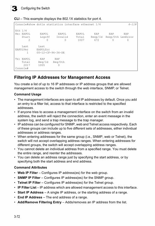
Configuring the Switch3
CLI – This example displays the 802.1X statistics for port 4.Filtering IP Addresses for Management AccessYou create a list of up to 16 IP addresses or IP address groups that are allowed management access to the switch through the web interface, SNMP, or Telnet.
Command Usage
• The management interfaces are open to all IP addresses by default. Once you add an entry to a filter list, access to that interface is restricted to the specified addresses.
• If anyone tries to access a management interface on the switch from an invalid address, the switch will reject the connection, enter an event message in the system log, and send a trap message to the trap manager.
• IP address can be configured for SNMP, web and Telnet access respectively. Each of these groups can include up to five different sets of addresses, either individual addresses or address ranges.
• When entering addresses for the same group (i.e., SNMP, web or Telnet), the switch will not accept overlapping address ranges. When entering addresses for different groups, the switch will accept overlapping address ranges.
• You cannot delete an individual address from a specified range. You must delete the entire range, and reenter the addresses.
• You can delete an address range just by specifying the start address, or by specifying both the start address and end address.
Command Attributes
• Web IP Filter – Configures IP address(es) for the web group.
• SNMP IP Filter – Configures IP address(es) for the SNMP group.
• Telnet IP Filter – Configures IP address(es) for the Telnet group.
• IP Filter List – IP address which are allowed management access to this interface.
• Start IP Address – A single IP address, or the starting address of a range.
• End IP Address – The end address of a range.
• Add/Remove Filtering Entry – Adds/removes an IP address from the list.
Console#show dot1x statistics interface ethernet 1/4 4-118
Eth 1/4Rx: EAPOL EAPOL EAPOL EAPOL EAP EAP EAP Start Logoff Invalid Total Resp/Id Resp/Oth LenError 2 0 0 1007 672 0 0
Last LastEAPOLVer EAPOLSrc 1 00-12-CF-94-34-DE
Tx: EAPOL EAP EAP Total Req/Id Req/Oth 2017 1005 0Console#
3-72
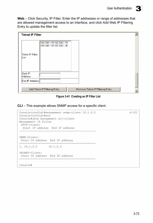
User Authentication 3
Web – Click Security, IP Filter. Enter the IP addresses or range of addresses that are allowed management access to an interface, and click Add Web IP Filtering Entry to update the filter list.Figure 3-41 Creating an IP Filter List
CLI – This example allows SNMP access for a specific client.
Console(config)#management snmp-client 10.1.2.3 4-121Console(config)#endConsole#show management all-clientManagement IP Filter HTTP-Client: Start IP address End IP address-----------------------------------------------
SNMP-Client: Start IP address End IP address-----------------------------------------------1. 10.1.2.3 10.1.2.3
TELNET-Client: Start IP address End IP address-----------------------------------------------
Console#
3-73
Configuring the Switch3
General Security Measures This switch supports many methods of segregating traffic for clients attached to each of the data ports, and for ensuring that only authorized clients gain access to the network. Private VLANs and port-based authentication using IEEE 802.1X are commonly used for these purposes. In addition to these methods, several other options of providing client security are supported by this switch. These include port-based authentication, which can be configured for network client access by specifying a fixed set of MAC addresses. The addresses assigned to DHCP clients can also be carefully controlled using static or dynamic bindings with the IP Source Guard and DHCP Snooping commands.This switch provides client security using the following options:
• Private VLANs – Provide port-based security and isolation between ports within the assigned VLAN. (See "Configuring Private VLANs" on page 3-165.)
• Port Security – Configure secure addresses for individual ports.• 802.1X – Use IEEE 802.1X port authentication to control access to specific ports.
(See "Configuring 802.1X Port Authentication" on page 3-65.)
• Network Access - Configures MAC authentication and dynamic VLAN assignment.
• ACL - Access Control Lists provide packet filtering for IPv4 frames (based on address, protocol, Layer 4 protocol port number or TCP control code), IPv6 frames (based on address, next header type, or flow label), or any frames (based on MAC address or Ethernet type).
• DHCP Snooping – Filters IP traffic on insecure ports for which the source address cannot be identified via DHCP snooping. (See "DHCP Snooping" on page 3-84.)
• IP Source Guard – Filters untrusted DHCP messages on insecure ports by building and maintaining a DHCP snooping binding table. (See "IP Source Guard" on page 3-90.)
Note: The priority of execution for the filtering commands is Port Security, Port Authentication, Network Access, Access Control Lists, IP Source Guard, and then DHCP Snooping.
3-74
General Security Measures 3
Configuring Port SecurityPort security is a feature that allows you to configure a switch port with one or more device MAC addresses that are authorized to access the network through that port.When port security is enabled on a port, the switch stops learning new MAC addresses on the specified port when it has reached a configured maximum number. Only incoming traffic with source addresses already stored in the dynamic or static address table will be authorized to access the network through that port. If a device with an unauthorized MAC address attempts to use the switch port, the intrusion will be detected and the switch can automatically take action by disabling the port and sending a trap message.
To use port security, specify a maximum number of addresses to allow on the port and then let the switch dynamically learn the <source MAC address, VLAN> pair for frames received on the port. Note that you can also manually add secure addresses to the port using the Static Address Table (page 3-119). When the port has reached the maximum number of MAC addresses the selected port will stop learning. The MAC addresses already in the address table will be retained and will not age out. Any other device that attempts to use the port will be prevented from accessing the switch.
Command Usage
• A secure port has the following restrictions:
- It cannot be used as a member of a static or dynamic trunk.- It should not be connected to a network interconnection device.
• The default maximum number of MAC addresses allowed on a secure port is zero. You must configure a maximum address count from 1 - 1024 for the port to allow access.
• If a port is disabled (shut down) due to a security violation, it must be manually re-enabled from the Port/Port Configuration page (page 3-97).
Command Attributes
• Port – Port number.• Name – Descriptive text (page 4-156). • Action – Indicates the action to be taken when a port security violation is detected:
- None: No action should be taken. (This is the default.)- Trap: Send an SNMP trap message.- Shutdown: Disable the port.- Trap and Shutdown: Send an SNMP trap message and disable the port.
• Security Status – Enables or disables port security on the port. (Default: Disabled)• Max MAC Count – The maximum number of MAC addresses that can be learned
on a port. (Range: 0 - 1024, where 0 means disabled)• Trunk – Trunk number if port is a member (page 3-100 and 3-101).
3-75
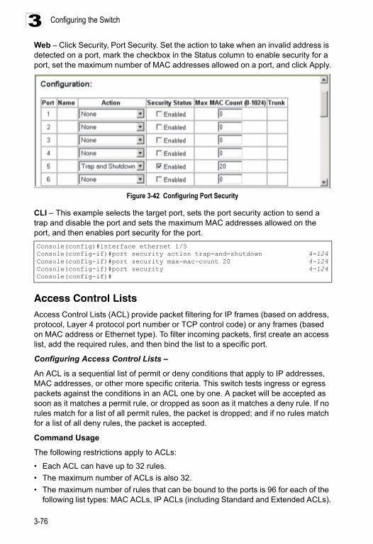
Configuring the Switch3
Web – Click Security, Port Security. Set the action to take when an invalid address is detected on a port, mark the checkbox in the Status column to enable security for a port, set the maximum number of MAC addresses allowed on a port, and click Apply.Figure 3-42 Configuring Port Security
CLI – This example selects the target port, sets the port security action to send a trap and disable the port and sets the maximum MAC addresses allowed on the port, and then enables port security for the port.
Access Control Lists Access Control Lists (ACL) provide packet filtering for IP frames (based on address, protocol, Layer 4 protocol port number or TCP control code) or any frames (based on MAC address or Ethernet type). To filter incoming packets, first create an access list, add the required rules, and then bind the list to a specific port.
Configuring Access Control Lists –
An ACL is a sequential list of permit or deny conditions that apply to IP addresses, MAC addresses, or other more specific criteria. This switch tests ingress or egress packets against the conditions in an ACL one by one. A packet will be accepted as soon as it matches a permit rule, or dropped as soon as it matches a deny rule. If no rules match for a list of all permit rules, the packet is dropped; and if no rules match for a list of all deny rules, the packet is accepted.
Command Usage
The following restrictions apply to ACLs:
• Each ACL can have up to 32 rules.
• The maximum number of ACLs is also 32.
• The maximum number of rules that can be bound to the ports is 96 for each of the following list types: MAC ACLs, IP ACLs (including Standard and Extended ACLs).
Console(config)#interface ethernet 1/5Console(config-if)#port security action trap-and-shutdown 4-124Console(config-if)#port security max-mac-count 20 4-124Console(config-if)#port security 4-124Console(config-if)#
3-76
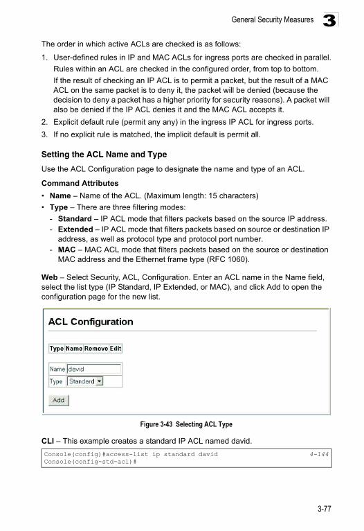
General Security Measures 3
The order in which active ACLs are checked is as follows:1. User-defined rules in IP and MAC ACLs for ingress ports are checked in parallel.
Rules within an ACL are checked in the configured order, from top to bottom.
If the result of checking an IP ACL is to permit a packet, but the result of a MAC ACL on the same packet is to deny it, the packet will be denied (because the decision to deny a packet has a higher priority for security reasons). A packet will also be denied if the IP ACL denies it and the MAC ACL accepts it.
2. Explicit default rule (permit any any) in the ingress IP ACL for ingress ports.
3. If no explicit rule is matched, the implicit default is permit all.
Setting the ACL Name and Type
Use the ACL Configuration page to designate the name and type of an ACL.
Command Attributes
• Name – Name of the ACL. (Maximum length: 15 characters)
• Type – There are three filtering modes:
- Standard – IP ACL mode that filters packets based on the source IP address.- Extended – IP ACL mode that filters packets based on source or destination IP
address, as well as protocol type and protocol port number.- MAC – MAC ACL mode that filters packets based on the source or destination
MAC address and the Ethernet frame type (RFC 1060).
Web – Select Security, ACL, Configuration. Enter an ACL name in the Name field, select the list type (IP Standard, IP Extended, or MAC), and click Add to open the configuration page for the new list.
Figure 3-43 Selecting ACL Type
CLI – This example creates a standard IP ACL named david.
Console(config)#access-list ip standard david 4-144Console(config-std-acl)#
3-77
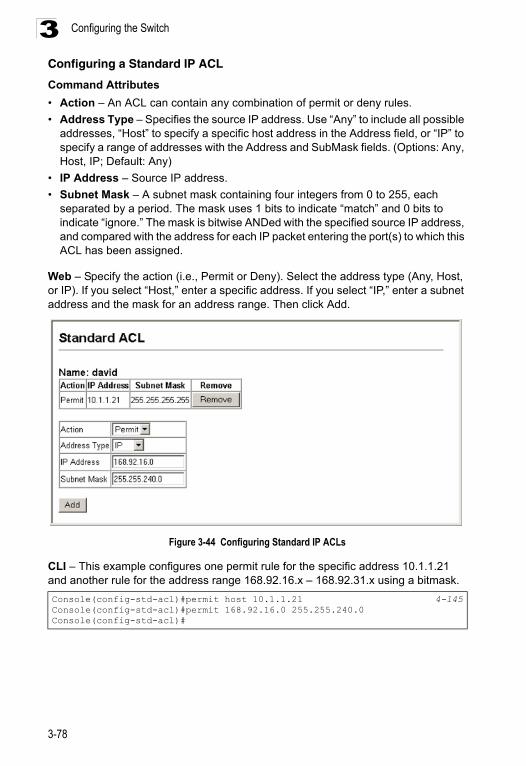
Configuring the Switch3
Configuring a Standard IP ACLCommand Attributes
• Action – An ACL can contain any combination of permit or deny rules.
• Address Type – Specifies the source IP address. Use “Any” to include all possible addresses, “Host” to specify a specific host address in the Address field, or “IP” to specify a range of addresses with the Address and SubMask fields. (Options: Any, Host, IP; Default: Any)
• IP Address – Source IP address.
• Subnet Mask – A subnet mask containing four integers from 0 to 255, each separated by a period. The mask uses 1 bits to indicate “match” and 0 bits to indicate “ignore.” The mask is bitwise ANDed with the specified source IP address, and compared with the address for each IP packet entering the port(s) to which this ACL has been assigned.
Web – Specify the action (i.e., Permit or Deny). Select the address type (Any, Host, or IP). If you select “Host,” enter a specific address. If you select “IP,” enter a subnet address and the mask for an address range. Then click Add.
Figure 3-44 Configuring Standard IP ACLs
CLI – This example configures one permit rule for the specific address 10.1.1.21 and another rule for the address range 168.92.16.x – 168.92.31.x using a bitmask.
Console(config-std-acl)#permit host 10.1.1.21 4-145Console(config-std-acl)#permit 168.92.16.0 255.255.240.0Console(config-std-acl)#
3-78
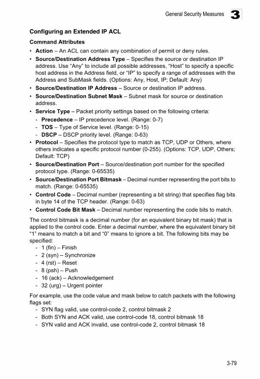
General Security Measures 3
Configuring an Extended IP ACLCommand Attributes
• Action – An ACL can contain any combination of permit or deny rules.
• Source/Destination Address Type – Specifies the source or destination IP address. Use “Any” to include all possible addresses, “Host” to specify a specific host address in the Address field, or “IP” to specify a range of addresses with the Address and SubMask fields. (Options: Any, Host, IP; Default: Any)
• Source/Destination IP Address – Source or destination IP address.
• Source/Destination Subnet Mask – Subnet mask for source or destination address.
• Service Type – Packet priority settings based on the following criteria:
- Precedence – IP precedence level. (Range: 0-7)- TOS – Type of Service level. (Range: 0-15)- DSCP – DSCP priority level. (Range: 0-63)
• Protocol – Specifies the protocol type to match as TCP, UDP or Others, where others indicates a specific protocol number (0-255). (Options: TCP, UDP, Others; Default: TCP)
• Source/Destination Port – Source/destination port number for the specified protocol type. (Range: 0-65535)
• Source/Destination Port Bitmask – Decimal number representing the port bits to match. (Range: 0-65535)
• Control Code – Decimal number (representing a bit string) that specifies flag bits in byte 14 of the TCP header. (Range: 0-63)
• Control Code Bit Mask – Decimal number representing the code bits to match.
The control bitmask is a decimal number (for an equivalent binary bit mask) that is applied to the control code. Enter a decimal number, where the equivalent binary bit “1” means to match a bit and “0” means to ignore a bit. The following bits may be specified:
- 1 (fin) – Finish- 2 (syn) – Synchronize- 4 (rst) – Reset- 8 (psh) – Push- 16 (ack) – Acknowledgement- 32 (urg) – Urgent pointer
For example, use the code value and mask below to catch packets with the following flags set:
- SYN flag valid, use control-code 2, control bitmask 2- Both SYN and ACK valid, use control-code 18, control bitmask 18- SYN valid and ACK invalid, use control-code 2, control bitmask 18
3-79
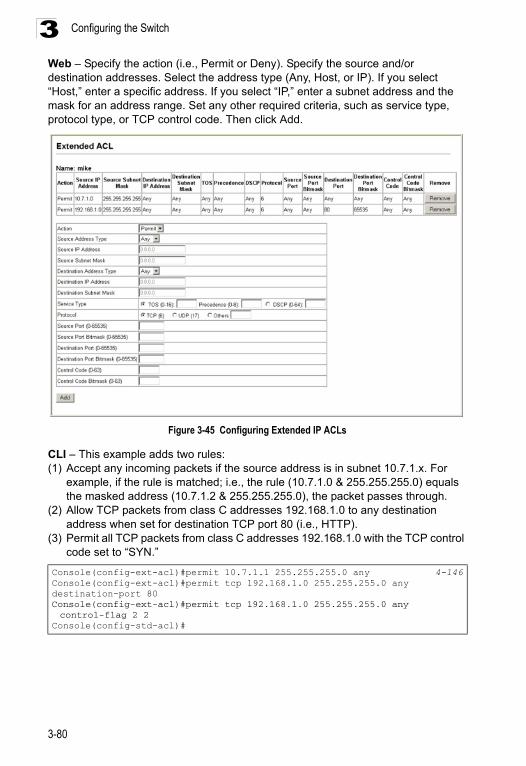
Configuring the Switch3
Web – Specify the action (i.e., Permit or Deny). Specify the source and/or destination addresses. Select the address type (Any, Host, or IP). If you select “Host,” enter a specific address. If you select “IP,” enter a subnet address and the mask for an address range. Set any other required criteria, such as service type, protocol type, or TCP control code. Then click Add.Figure 3-45 Configuring Extended IP ACLs
CLI – This example adds two rules:(1) Accept any incoming packets if the source address is in subnet 10.7.1.x. For
example, if the rule is matched; i.e., the rule (10.7.1.0 & 255.255.255.0) equals the masked address (10.7.1.2 & 255.255.255.0), the packet passes through.
(2) Allow TCP packets from class C addresses 192.168.1.0 to any destination address when set for destination TCP port 80 (i.e., HTTP).
(3) Permit all TCP packets from class C addresses 192.168.1.0 with the TCP control code set to “SYN.”
Console(config-ext-acl)#permit 10.7.1.1 255.255.255.0 any 4-146Console(config-ext-acl)#permit tcp 192.168.1.0 255.255.255.0 any destination-port 80Console(config-ext-acl)#permit tcp 192.168.1.0 255.255.255.0 any control-flag 2 2
Console(config-std-acl)#
3-80
General Security Measures 3
Configuring a MAC ACLUse this page to configure ACLs based on hardware addresses, packet format, and Ethernet type.
Command Attributes
• Action – An ACL can contain any combination of permit or deny rules.
• Source/Destination Address Type – Use “Any” to include all possible addresses, “Host” to indicate a specific MAC address, or “MAC” to specify an address range with the Address and Bitmask fields. (Options: Any, Host, MAC; Default: Any)
• Source/Destination MAC Address – Source or destination MAC address.
• Source/Destination Bitmask – Hexadecimal mask for source or destination MAC address.
• VID – VLAN ID. (Range: 1-4094)
• VID Mask – VLAN bitmask. (Range: 1-4094)
• Ethernet Type – This option can only be used to filter Ethernet II formatted packets. (Range: 600-fff hex.)
A detailed listing of Ethernet protocol types can be found in RFC 1060. A few of the more common types include 0800 (IP), 0806 (ARP), 8137 (IPX).
• Ethernet Type Bitmask – Protocol bitmask. (Range: 600-fff hex.)
• Packet Format – This attribute includes the following packet types:
- Any – Any Ethernet packet type.- Untagged-eth2 – Untagged Ethernet II packets.- Untagged-802.3 – Untagged Ethernet 802.3 packets.- Tagged-802.3 – Tagged Ethernet 802.3 packets.- Tagged-802.3 – Tagged Ethernet 802.3 packets.
Command Usage
Egress MAC ACLs only work for destination-mac-known packets, not for multicast, broadcast, or destination-mac-unknown packets.
3-81
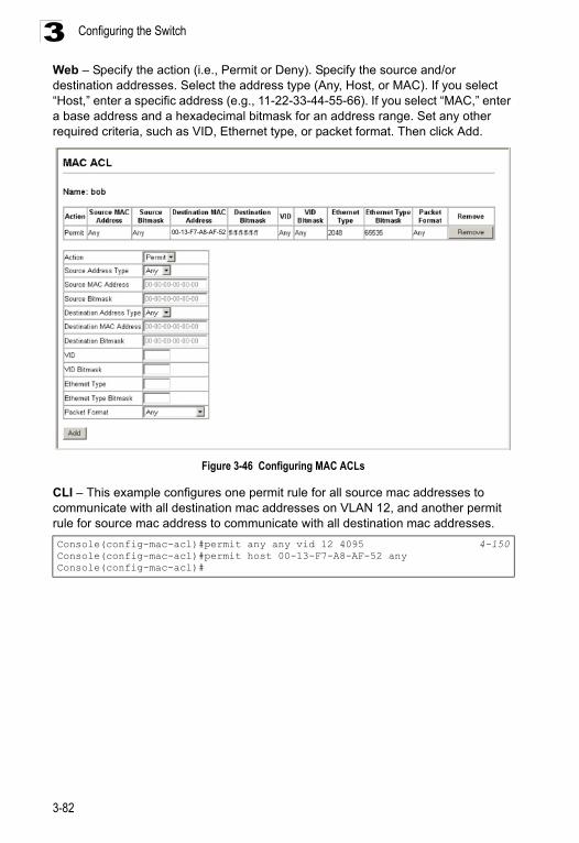
Configuring the Switch3
Web – Specify the action (i.e., Permit or Deny). Specify the source and/or destination addresses. Select the address type (Any, Host, or MAC). If you select “Host,” enter a specific address (e.g., 11-22-33-44-55-66). If you select “MAC,” enter a base address and a hexadecimal bitmask for an address range. Set any other required criteria, such as VID, Ethernet type, or packet format. Then click Add.Figure 3-46 Configuring MAC ACLs
CLI – This example configures one permit rule for all source mac addresses to communicate with all destination mac addresses on VLAN 12, and another permit rule for source mac address to communicate with all destination mac addresses.
Console(config-mac-acl)#permit any any vid 12 4095 4-150Console(config-mac-acl)#permit host 00-13-F7-A8-AF-52 anyConsole(config-mac-acl)#
00-13-F7-A8-AF-52
3-82
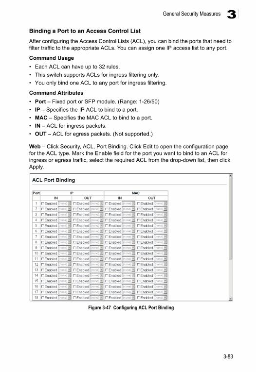
General Security Measures 3
Binding a Port to an Access Control ListAfter configuring the Access Control Lists (ACL), you can bind the ports that need to filter traffic to the appropriate ACLs. You can assign one IP access list to any port.
Command Usage
• Each ACL can have up to 32 rules.
• This switch supports ACLs for ingress filtering only.
• You only bind one ACL to any port for ingress filtering.
Command Attributes
• Port – Fixed port or SFP module. (Range: 1-26/50)
• IP – Specifies the IP ACL to bind to a port.
• MAC – Specifies the MAC ACL to bind to a port.
• IN – ACL for ingress packets.
• OUT – ACL for egress packets. (Not supported.)
Web – Click Security, ACL, Port Binding. Click Edit to open the configuration page for the ACL type. Mark the Enable field for the port you want to bind to an ACL for ingress or egress traffic, select the required ACL from the drop-down list, then click Apply.
Figure 3-47 Configuring ACL Port Binding
3-83
Configuring the Switch3
CLI – This example assigns an IP access list to port 1, and an IP access list to port 3.DHCP SnoopingThe addresses assigned to DHCP clients on insecure ports can be carefully controlled using the dynamic bindings registered with DHCP Snooping (or using the static bindings configured with IP Source Guard). DHCP snooping allows a switch to protect a network from rogue DHCP servers or other devices which send port-related information to a DHCP server. This information can be useful in tracking an IP address back to a physical port.
Command Usage
• Network traffic may be disrupted when malicious DHCP messages are received from an outside source. DHCP snooping is used to filter DHCP messages received on a non-secure interface from outside the network or firewall. When DHCP snooping is enabled globally and enabled on a VLAN interface, DHCP messages received on an untrusted interface from a device not listed in the DHCP snooping table will be dropped.
• Table entries are only learned for trusted interfaces. An entry is added or removed dynamically to the DHCP snooping table when a client receives or releases an IP address from a DHCP server. Each entry includes a MAC address, IP address, lease time, VLAN identifier, and port identifier.
• The rate limit for the number of DHCP messages that can be processed by the switch is 100 packets per second. Any DHCP packets in excess of this limit are dropped.
• When DHCP snooping is enabled, DHCP messages entering an untrusted interface are filtered based upon dynamic entries learned via DHCP snooping.
• Filtering rules are implemented as follows:
- If the global DHCP snooping is disabled, all DHCP packets are forwarded.
- If DHCP snooping is enabled globally, and also enabled on the VLAN where the DHCP packet is received, all DHCP packets are forwarded for a trusted port. If the received packet is a DHCP ACK message, a dynamic DHCP snooping entry is also added to the binding table.
- If DHCP snooping is enabled globally, and also enabled on the VLAN where the DHCP packet is received, but the port is not trusted, it is processed as follows:
* If the DHCP packet is a reply packet from a DHCP server (including OFFER, ACK or NAK messages), the packet is dropped.
Console(config)#interface ethernet 1/1 4-155Console(config-if)#ip access-group david in 4-148Console(config-if)#exitConsole(config)#interface ethernet 1/3Console(config-if)#ip access-group david inConsole(config-if)#
3-84
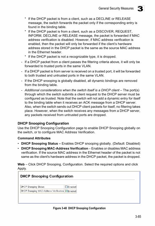
General Security Measures 3
* If the DHCP packet is from a client, such as a DECLINE or RELEASEmessage, the switch forwards the packet only if the corresponding entry is found in the binding table.
* If the DHCP packet is from a client, such as a DISCOVER, REQUEST, INFORM, DECLINE or RELEASE message, the packet is forwarded if MAC address verification is disabled. However, if MAC address verification is enabled, then the packet will only be forwarded if the client’s hardware address stored in the DHCP packet is the same as the source MAC address in the Ethernet header.
* If the DHCP packet is not a recognizable type, it is dropped.
- If a DHCP packet from a client passes the filtering criteria above, it will only be forwarded to trusted ports in the same VLAN.
- If a DHCP packet is from server is received on a trusted port, it will be forwarded to both trusted and untrusted ports in the same VLAN.
- If the DHCP snooping is globally disabled, all dynamic bindings are removed from the binding table.
- Additional considerations when the switch itself is a DHCP client – The port(s) through which the switch submits a client request to the DHCP server must be configured as trusted. Note that the switch will not add a dynamic entry for itself to the binding table when it receives an ACK message from a DHCP server. Also, when the switch sends out DHCP client packets for itself, no filtering takes place. However, when the switch receives any messages from a DHCP server, any packets received from untrusted ports are dropped.
DHCP Snooping ConfigurationUse the DHCP Snooping Configuration page to enable DHCP Snooping globally on the switch, or to configure MAC Address Verification.
Command Attributes
• DHCP Snooping Status – Enables DHCP snooping globally. (Default: Disabled)
• DHCP Snooping MAC-Address Verification – Enables or disables MAC address verification. If the source MAC address in the Ethernet header of the packet is not same as the client's hardware address in the DHCP packet, the packet is dropped.
Web – Click DHCP Snooping, Configuration. Select the required options and click Apply.
Figure 3-48 DHCP Snooping Configuration
3-85
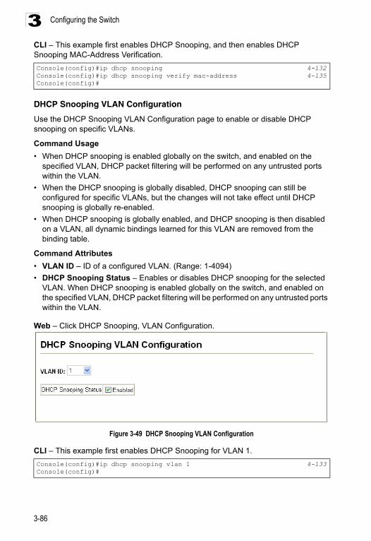
Configuring the Switch3
CLI – This example first enables DHCP Snooping, and then enables DHCP Snooping MAC-Address Verification.DHCP Snooping VLAN Configuration
Use the DHCP Snooping VLAN Configuration page to enable or disable DHCP snooping on specific VLANs.
Command Usage
• When DHCP snooping is enabled globally on the switch, and enabled on the specified VLAN, DHCP packet filtering will be performed on any untrusted ports within the VLAN.
• When the DHCP snooping is globally disabled, DHCP snooping can still be configured for specific VLANs, but the changes will not take effect until DHCP snooping is globally re-enabled.
• When DHCP snooping is globally enabled, and DHCP snooping is then disabled on a VLAN, all dynamic bindings learned for this VLAN are removed from the binding table.
Command Attributes
• VLAN ID – ID of a configured VLAN. (Range: 1-4094)
• DHCP Snooping Status – Enables or disables DHCP snooping for the selected VLAN. When DHCP snooping is enabled globally on the switch, and enabled on the specified VLAN, DHCP packet filtering will be performed on any untrusted ports within the VLAN.
Web – Click DHCP Snooping, VLAN Configuration.
Figure 3-49 DHCP Snooping VLAN Configuration
CLI – This example first enables DHCP Snooping for VLAN 1.
Console(config)#ip dhcp snooping 4-132Console(config)#ip dhcp snooping verify mac-address 4-135Console(config)#
Console(config)#ip dhcp snooping vlan 1 4-133Console(config)#
3-86
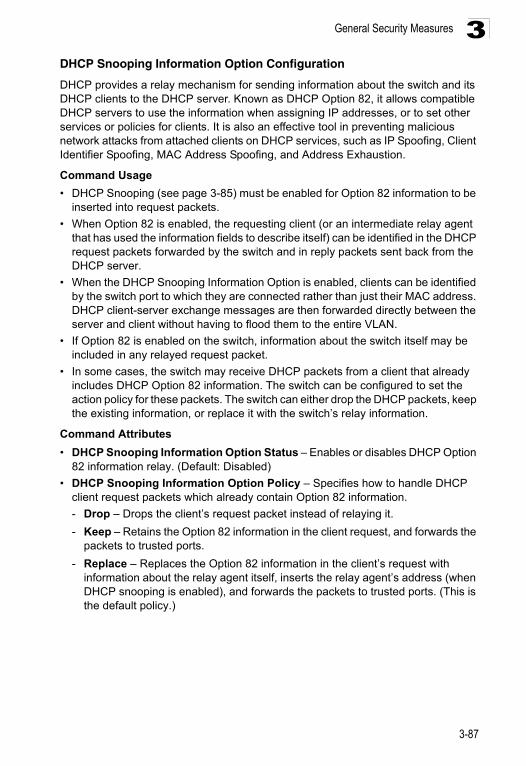
General Security Measures 3
DHCP Snooping Information Option ConfigurationDHCP provides a relay mechanism for sending information about the switch and its DHCP clients to the DHCP server. Known as DHCP Option 82, it allows compatible DHCP servers to use the information when assigning IP addresses, or to set other services or policies for clients. It is also an effective tool in preventing malicious network attacks from attached clients on DHCP services, such as IP Spoofing, Client Identifier Spoofing, MAC Address Spoofing, and Address Exhaustion.
Command Usage
• DHCP Snooping (see page 3-85) must be enabled for Option 82 information to be inserted into request packets.
• When Option 82 is enabled, the requesting client (or an intermediate relay agent that has used the information fields to describe itself) can be identified in the DHCP request packets forwarded by the switch and in reply packets sent back from the DHCP server.
• When the DHCP Snooping Information Option is enabled, clients can be identified by the switch port to which they are connected rather than just their MAC address. DHCP client-server exchange messages are then forwarded directly between the server and client without having to flood them to the entire VLAN.
• If Option 82 is enabled on the switch, information about the switch itself may be included in any relayed request packet.
• In some cases, the switch may receive DHCP packets from a client that already includes DHCP Option 82 information. The switch can be configured to set the action policy for these packets. The switch can either drop the DHCP packets, keep the existing information, or replace it with the switch’s relay information.
Command Attributes
• DHCP Snooping Information Option Status – Enables or disables DHCP Option 82 information relay. (Default: Disabled)
• DHCP Snooping Information Option Policy – Specifies how to handle DHCP client request packets which already contain Option 82 information.
- Drop – Drops the client’s request packet instead of relaying it.
- Keep – Retains the Option 82 information in the client request, and forwards the packets to trusted ports.
- Replace – Replaces the Option 82 information in the client’s request with information about the relay agent itself, inserts the relay agent’s address (when DHCP snooping is enabled), and forwards the packets to trusted ports. (This is the default policy.)
3-87
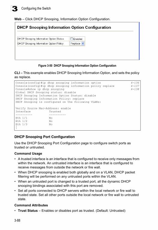
Configuring the Switch3
Web – Click DHCP Snooping, Information Option Configuration.Figure 3-50 DHCP Snooping Information Option Configuration
CLI – This example enables DHCP Snooping Information Option, and sets the policy as replace.
DHCP Snooping Port Configuration
Use the DHCP Snooping Port Configuration page to configure switch ports as trusted or untrusted.
Command Usage
• A trusted interface is an interface that is configured to receive only messages from within the network. An untrusted interface is an interface that is configured to receive messages from outside the network or fire wall.
• When DHCP snooping is enabled both globally and on a VLAN, DHCP packet filtering will be performed on any untrusted ports within the VLAN.
• When an untrusted port is changed to a trusted port, all the dynamic DHCP snooping bindings associated with this port are removed.
• Set all ports connected to DHCP servers within the local network or fire wall to trusted state. Set all other ports outside the local network or fire wall to untrusted state.
Command Attributes
• Trust Status – Enables or disables port as trusted. (Default: Untrusted)
Console(config)#ip dhcp snooping information option 4-136Console(config)#ip dhcp snooping information policy replace 4-137Console#show ip dhcp snooping 4-138Global DHCP Snooping status: disableDHCP Snooping Information Option Status: disableDHCP Snooping Information Policy: replaceDHCP Snooping is configured on the following VLANs:
Verify Source Mac-Address: enableInterface Trusted ---------- ----------Eth 1/1 NoEth 1/2 NoEth 1/3 No...
3-88
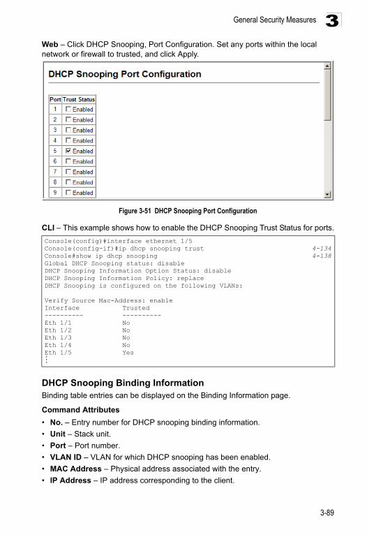
General Security Measures 3
Web – Click DHCP Snooping, Port Configuration. Set any ports within the local network or firewall to trusted, and click Apply.Figure 3-51 DHCP Snooping Port Configuration
CLI – This example shows how to enable the DHCP Snooping Trust Status for ports.
DHCP Snooping Binding InformationBinding table entries can be displayed on the Binding Information page.
Command Attributes
• No. – Entry number for DHCP snooping binding information.
• Unit – Stack unit.
• Port – Port number.
• VLAN ID – VLAN for which DHCP snooping has been enabled.
• MAC Address – Physical address associated with the entry.
• IP Address – IP address corresponding to the client.
Console(config)#interface ethernet 1/5Console(config-if)#ip dhcp snooping trust 4-134Console#show ip dhcp snooping 4-138Global DHCP Snooping status: disableDHCP Snooping Information Option Status: disableDHCP Snooping Information Policy: replaceDHCP Snooping is configured on the following VLANs:
Verify Source Mac-Address: enableInterface Trusted ---------- ----------Eth 1/1 NoEth 1/2 NoEth 1/3 NoEth 1/4 NoEth 1/5 Yes...
3-89
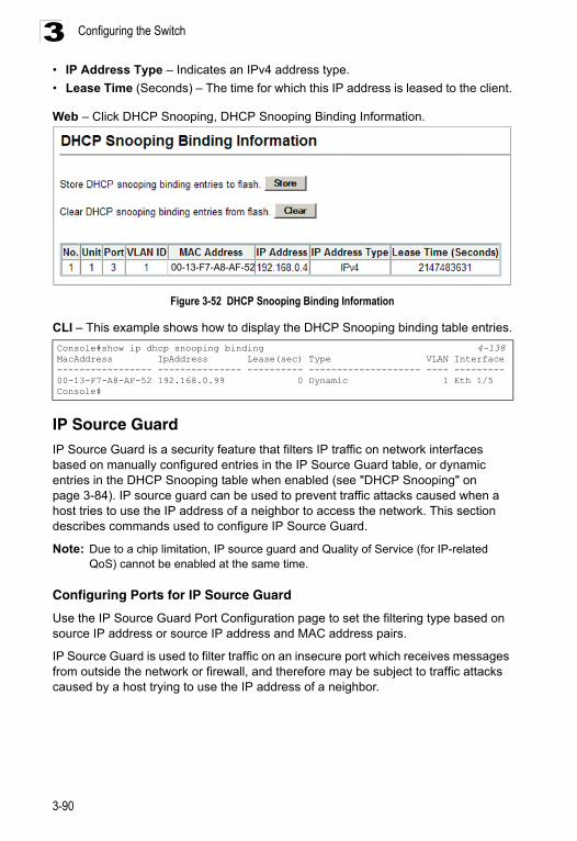
Configuring the Switch3
• IP Address Type – Indicates an IPv4 address type.• Lease Time (Seconds) – The time for which this IP address is leased to the client.
Web – Click DHCP Snooping, DHCP Snooping Binding Information.
Figure 3-52 DHCP Snooping Binding Information
CLI – This example shows how to display the DHCP Snooping binding table entries.
IP Source GuardIP Source Guard is a security feature that filters IP traffic on network interfaces based on manually configured entries in the IP Source Guard table, or dynamic entries in the DHCP Snooping table when enabled (see "DHCP Snooping" on page 3-84). IP source guard can be used to prevent traffic attacks caused when a host tries to use the IP address of a neighbor to access the network. This section describes commands used to configure IP Source Guard.
Note: Due to a chip limitation, IP source guard and Quality of Service (for IP-related QoS) cannot be enabled at the same time.
Configuring Ports for IP Source Guard
Use the IP Source Guard Port Configuration page to set the filtering type based on source IP address or source IP address and MAC address pairs.
IP Source Guard is used to filter traffic on an insecure port which receives messages from outside the network or firewall, and therefore may be subject to traffic attacks caused by a host trying to use the IP address of a neighbor.
Console#show ip dhcp snooping binding 4-138MacAddress IpAddress Lease(sec) Type VLAN Interface----------------- --------------- ---------- -------------------- ---- ---------00-13-F7-A8-AF-52 192.168.0.99 0 Dynamic 1 Eth 1/5Console#
00-13-F7-A8-AF-52
3-90
General Security Measures 3
Command Usage• Setting source guard mode to SIP (Source IP) or SIP-MAC (Source IP and MAC) enables this function on the selected port. Use the SIP option to check the VLAN ID, source IP address, and port number against all entries in the binding table. Use the SIP-MAC option to check these same parameters, plus the source MAC address. If no matching entry is found, the packet is dropped.
• When enabled, traffic is filtered based upon dynamic entries learned via DHCP snooping (see "DHCP Snooping Configuration" on page 3-85), or static addresses configured in the source guard binding table.
• If IP source guard is enabled, an inbound packet’s IP address (SIP option) or both its IP address and corresponding MAC address (SIP-MAC option) will be checked against the binding table. If no matching entry is found, the packet will be dropped.
• Filtering rules are implemented as follows:
- If DHCP snooping is disabled (see page 3-85), IP source guard will check the VLAN ID, source IP address, port number, and source MAC address (for the SIP-MAC option). If a matching entry is found in the binding table and the entry type is static IP source guard binding, the packet will be forwarded.
- If DHCP snooping is enabled, IP source guard will check the VLAN ID, source IP address, port number, and source MAC address (for the SIP-MAC option). If a matching entry is found in the binding table and the entry type is static IP source guard binding, or dynamic DHCP snooping binding, the packet will be forwarded.
- If IP source guard if enabled on an interface for which IP source bindings have not yet been configured (neither by static configuration in the IP source guard binding table nor dynamically learned from DHCP snooping), the switch will drop all IP traffic on that port, except for DHCP packets.
Command Attributes
• Filter Type – Configures the switch to filter inbound traffic based source IP address, or source IP address and corresponding MAC address. (Default: None)
• None – Disables IP source guard filtering on the port.
• SIP – Enables traffic filtering based on IP addresses stored in the binding table.
• SIP-MAC – Enables traffic filtering based on IP addresses and corresponding MAC addresses stored in the binding table.
3-91
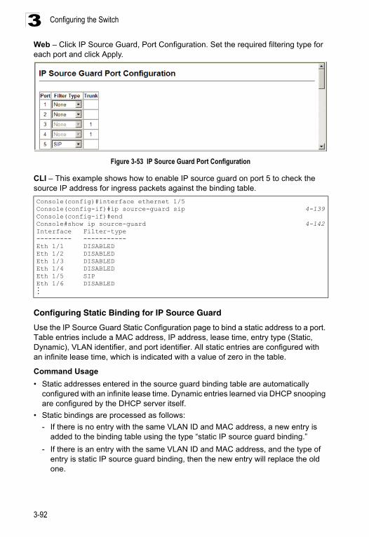
Configuring the Switch3
Web – Click IP Source Guard, Port Configuration. Set the required filtering type for each port and click Apply.Figure 3-53 IP Source Guard Port Configuration
CLI – This example shows how to enable IP source guard on port 5 to check the source IP address for ingress packets against the binding table.
Configuring Static Binding for IP Source Guard
Use the IP Source Guard Static Configuration page to bind a static address to a port. Table entries include a MAC address, IP address, lease time, entry type (Static, Dynamic), VLAN identifier, and port identifier. All static entries are configured with an infinite lease time, which is indicated with a value of zero in the table.
Command Usage
• Static addresses entered in the source guard binding table are automatically configured with an infinite lease time. Dynamic entries learned via DHCP snooping are configured by the DHCP server itself.
• Static bindings are processed as follows:
- If there is no entry with the same VLAN ID and MAC address, a new entry is added to the binding table using the type “static IP source guard binding.”
- If there is an entry with the same VLAN ID and MAC address, and the type of entry is static IP source guard binding, then the new entry will replace the old one.
Console(config)#interface ethernet 1/5Console(config-if)#ip source-guard sip 4-139Console(config-if)#endConsole#show ip source-guard 4-142Interface Filter-type--------- -----------Eth 1/1 DISABLEDEth 1/2 DISABLEDEth 1/3 DISABLEDEth 1/4 DISABLEDEth 1/5 SIPEth 1/6 DISABLED...
3-92
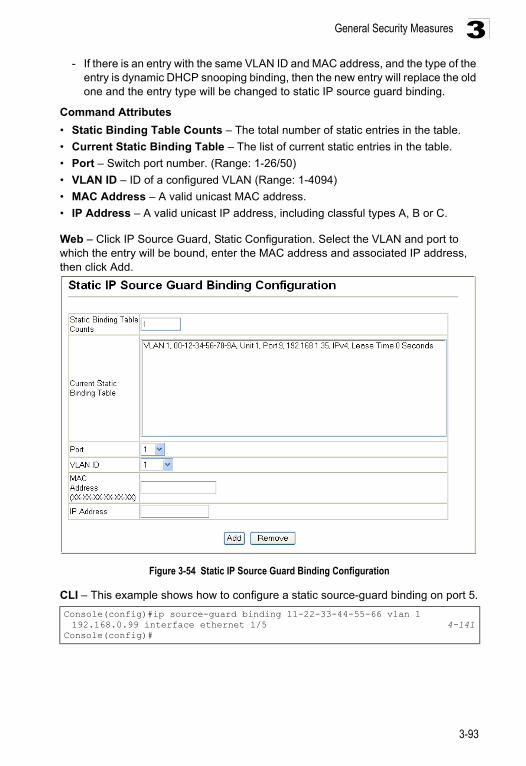
General Security Measures 3
- If there is an entry with the same VLAN ID and MAC address, and the type of theentry is dynamic DHCP snooping binding, then the new entry will replace the old one and the entry type will be changed to static IP source guard binding.
Command Attributes
• Static Binding Table Counts – The total number of static entries in the table.
• Current Static Binding Table – The list of current static entries in the table.
• Port – Switch port number. (Range: 1-26/50)
• VLAN ID – ID of a configured VLAN (Range: 1-4094)
• MAC Address – A valid unicast MAC address.
• IP Address – A valid unicast IP address, including classful types A, B or C.
Web – Click IP Source Guard, Static Configuration. Select the VLAN and port to which the entry will be bound, enter the MAC address and associated IP address, then click Add.
Figure 3-54 Static IP Source Guard Binding Configuration
CLI – This example shows how to configure a static source-guard binding on port 5.
Console(config)#ip source-guard binding 11-22-33-44-55-66 vlan 1 192.168.0.99 interface ethernet 1/5 4-141
Console(config)#
3-93
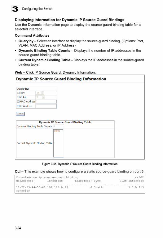
Configuring the Switch3
Displaying Information for Dynamic IP Source Guard BindingsUse the Dynamic Information page to display the source-guard binding table for a selected interface.Command Attributes
• Query by – Select an interface to display the source-guard binding. (Options: Port, VLAN, MAC Address, or IP Address)
• Dynamic Binding Table Counts – Displays the number of IP addresses in the source-guard binding table.
• Current Dynamic Binding Table – Displays the IP addresses in the source-guard binding table.
Web – Click IP Source Guard, Dynamic Information.
Figure 3-55 Dynamic IP Source Guard Binding Information
CLI – This example shows how to configure a static source-guard binding on port 5.
Console#show ip source-guard binding 4-142MacAddress IpAddress Lease(sec) Type VLAN Interface----------------- --------------- ---------- -------------------- --------11-22-33-44-55-66 192.168.0.99 0 Static 1 Eth 1/5Console#
3-94
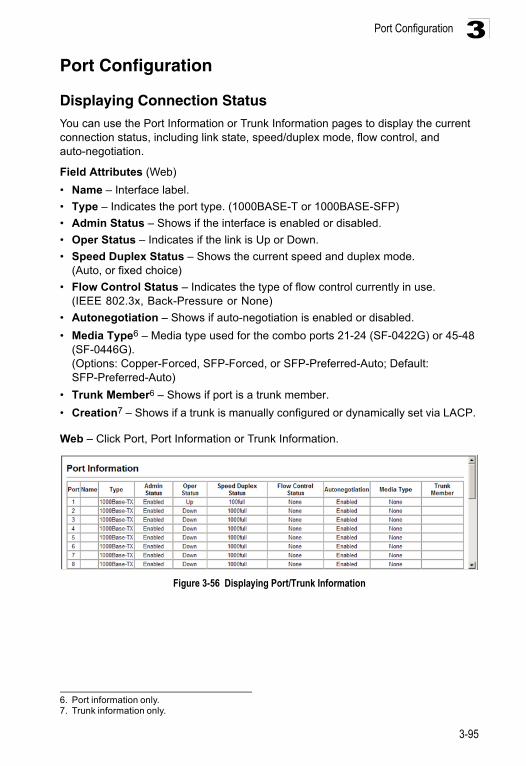
Port Configuration 3
Port ConfigurationDisplaying Connection StatusYou can use the Port Information or Trunk Information pages to display the current connection status, including link state, speed/duplex mode, flow control, and auto-negotiation.
Field Attributes (Web)
• Name – Interface label.
• Type – Indicates the port type. (1000BASE-T or 1000BASE-SFP)
• Admin Status – Shows if the interface is enabled or disabled.
• Oper Status – Indicates if the link is Up or Down.
• Speed Duplex Status – Shows the current speed and duplex mode. (Auto, or fixed choice)
• Flow Control Status – Indicates the type of flow control currently in use.(IEEE 802.3x, Back-Pressure or None)
• Autonegotiation – Shows if auto-negotiation is enabled or disabled.
• Media Type6 – Media type used for the combo ports 21-24 (SF-0422G) or 45-48 (SF-0446G).(Options: Copper-Forced, SFP-Forced, or SFP-Preferred-Auto; Default: SFP-Preferred-Auto)
• Trunk Member6 – Shows if port is a trunk member.
• Creation7 – Shows if a trunk is manually configured or dynamically set via LACP.
Web – Click Port, Port Information or Trunk Information.
Figure 3-56 Displaying Port/Trunk Information
6. Port information only.7. Trunk information only.
3-95
Configuring the Switch3
Field Attributes (CLI)Basic Information:
• Port Type – Indicates the port type. (1000BASE-T or 1000BASE-SFP)
• MAC address – The physical layer address for this port. (To access this item on the web, see 3-15.)
Configuration:
• Name – Interface label.
• Port admin – Shows if the interface is enabled or disabled (i.e., up or down).
• Speed-duplex – Shows the current speed and duplex mode. (Auto, or fixed choice)
• Capabilities – Specifies the capabilities to be advertised for a port during auto-negotiation. (To access this item on the web, see "Configuring Interface Connections" on page 3-97.) The following capabilities are supported. - 10half - Supports 10 Mbps half-duplex operation - 10full - Supports 10 Mbps full-duplex operation - 100half - Supports 100 Mbps half-duplex operation - 100full - Supports 100 Mbps full-duplex operation - 1000full - Supports 1000 Mbps full-duplex operation - Sym - Transmits and receives pause frames for flow control- FC - Supports flow control
• Broadcast Storm – Shows if broadcast storm control is enabled or disabled.
• Broadcast Storm Limit – Shows the broadcast storm threshold. (500-262143 packets per second)
• Flow Control – Shows if flow control is enabled or disabled.
• LACP – Shows if LACP is enabled or disabled.
• Port Security – Shows if port security is enabled or disabled.
• Max MAC count – Shows the maximum number of MAC address that can be learned by a port. (0 - 1024 addresses)
• Port Security Action – Shows the response to take when a security violation is detected. (shutdown, trap, trap-and-shutdown, or none)
• Media Type – Shows the forced or preferred port type to use for combination ports 21-24/45-48. (Display options: copper forced, SFP forced, SFP preferred auto)
Current Status:
• Link Status – Indicates if the link is up or down.
• Port Operation Status – Provides detailed information on port state. (Displayed only when the link is up.)
• Operation Speed-duplex – Shows the current speed and duplex mode.
• Flow Control Type – Indicates the type of flow control currently in use.(IEEE 802.3x, Back-Pressure or none)
3-96
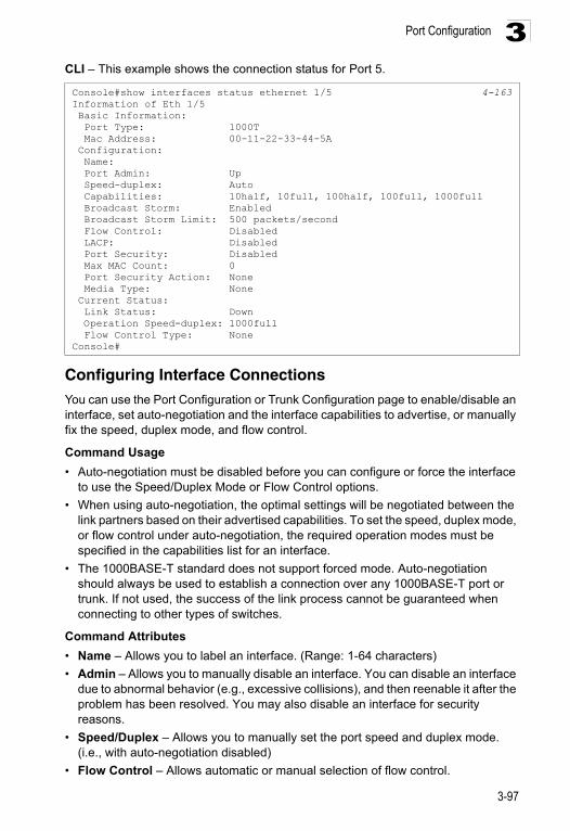
Port Configuration 3
CLI – This example shows the connection status for Port 5.Configuring Interface ConnectionsYou can use the Port Configuration or Trunk Configuration page to enable/disable an interface, set auto-negotiation and the interface capabilities to advertise, or manually fix the speed, duplex mode, and flow control.
Command Usage
• Auto-negotiation must be disabled before you can configure or force the interface to use the Speed/Duplex Mode or Flow Control options.
• When using auto-negotiation, the optimal settings will be negotiated between the link partners based on their advertised capabilities. To set the speed, duplex mode, or flow control under auto-negotiation, the required operation modes must be specified in the capabilities list for an interface.
• The 1000BASE-T standard does not support forced mode. Auto-negotiation should always be used to establish a connection over any 1000BASE-T port or trunk. If not used, the success of the link process cannot be guaranteed when connecting to other types of switches.
Command Attributes
• Name – Allows you to label an interface. (Range: 1-64 characters)
• Admin – Allows you to manually disable an interface. You can disable an interface due to abnormal behavior (e.g., excessive collisions), and then reenable it after the problem has been resolved. You may also disable an interface for security reasons.
• Speed/Duplex – Allows you to manually set the port speed and duplex mode. (i.e., with auto-negotiation disabled)
• Flow Control – Allows automatic or manual selection of flow control.
Console#show interfaces status ethernet 1/5 4-163Information of Eth 1/5 Basic Information: Port Type: 1000T Mac Address: 00-11-22-33-44-5A Configuration: Name: Port Admin: Up Speed-duplex: Auto Capabilities: 10half, 10full, 100half, 100full, 1000full Broadcast Storm: Enabled Broadcast Storm Limit: 500 packets/second Flow Control: Disabled LACP: Disabled Port Security: Disabled Max MAC Count: 0 Port Security Action: None Media Type: None Current Status: Link Status: Down Operation Speed-duplex: 1000full Flow Control Type: NoneConsole#
3-97
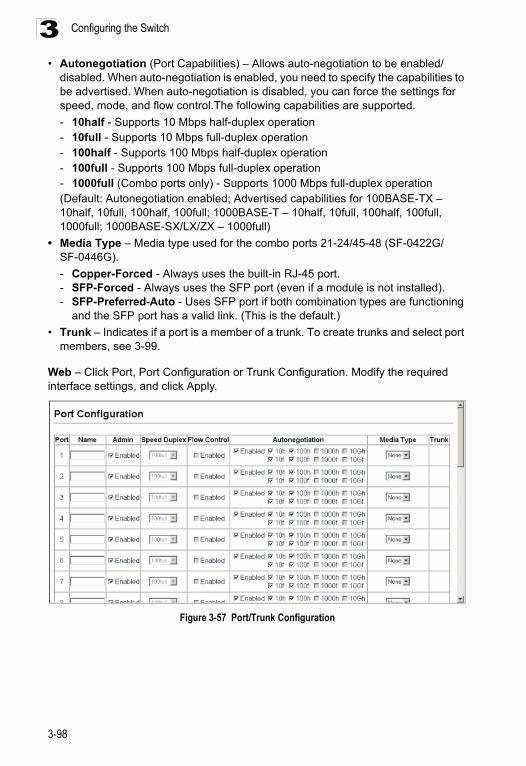
Configuring the Switch3
• Autonegotiation (Port Capabilities) – Allows auto-negotiation to be enabled/disabled. When auto-negotiation is enabled, you need to specify the capabilities to be advertised. When auto-negotiation is disabled, you can force the settings for speed, mode, and flow control.The following capabilities are supported.
- 10half - Supports 10 Mbps half-duplex operation- 10full - Supports 10 Mbps full-duplex operation - 100half - Supports 100 Mbps half-duplex operation - 100full - Supports 100 Mbps full-duplex operation - 1000full (Combo ports only) - Supports 1000 Mbps full-duplex operation (Default: Autonegotiation enabled; Advertised capabilities for 100BASE-TX – 10half, 10full, 100half, 100full; 1000BASE-T – 10half, 10full, 100half, 100full, 1000full; 1000BASE-SX/LX/ZX – 1000full)
• Media Type – Media type used for the combo ports 21-24/45-48 (SF-0422G/SF-0446G).
- Copper-Forced - Always uses the built-in RJ-45 port.- SFP-Forced - Always uses the SFP port (even if a module is not installed).- SFP-Preferred-Auto - Uses SFP port if both combination types are functioning
and the SFP port has a valid link. (This is the default.)
• Trunk – Indicates if a port is a member of a trunk. To create trunks and select port members, see 3-99.
Web – Click Port, Port Configuration or Trunk Configuration. Modify the required interface settings, and click Apply.
Figure 3-57 Port/Trunk Configuration
3-98
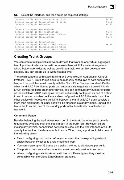
Port Configuration 3
CLI – Select the interface, and then enter the required settings.Creating Trunk Groups
You can create multiple links between devices that work as one virtual, aggregate link. A port trunk offers a dramatic increase in bandwidth for network segments where bottlenecks exist, as well as providing a fault-tolerant link between two devices. You can create up to 32 trunks at a time.
The switch supports both static trunking and dynamic Link Aggregation Control Protocol (LACP). Static trunks have to be manually configured at both ends of the link, and the switches must comply with the Cisco EtherChannel standard. On the other hand, LACP configured ports can automatically negotiate a trunked link with LACP-configured ports on another device. You can configure any number of ports on the switch as LACP, as long as they are not already configured as part of a static trunk. If ports on another device are also configured as LACP, the switch and the other device will negotiate a trunk link between them. If an LACP trunk consists of more than eight ports, all other ports will be placed in a standby mode. Should one link in the trunk fail, one of the standby ports will automatically be activated to replace it.
Command Usage
Besides balancing the load across each port in the trunk, the other ports provide redundancy by taking over the load if a port in the trunk fails. However, before making any physical connections between devices, use the web interface or CLI to specify the trunk on the devices at both ends. When using a port trunk, take note of the following points:
• Finish configuring port trunks before you connect the corresponding network cables between switches to avoid creating a loop.
• You can create up to 32 trunks on a switch, with up to eight ports per trunk.
• The ports at both ends of a connection must be configured as trunk ports.
• When configuring static trunks on switches of different types, they must be compatible with the Cisco EtherChannel standard.
Console(config)#interface ethernet 1/13 4-155Console(config-if)#description RD SW#13 4-156Console(config-if)#shutdown 4-160.Console(config-if)#no shutdownConsole(config-if)#no negotiation 4-157Console(config-if)#speed-duplex 100half 4-156Console(config-if)#flowcontrol 4-159.Console(config-if)#negotiationConsole(config-if)#capabilities 100half 4-158Console(config-if)#capabilities 100full Console(config-if)#capabilities flowcontrol
3-99
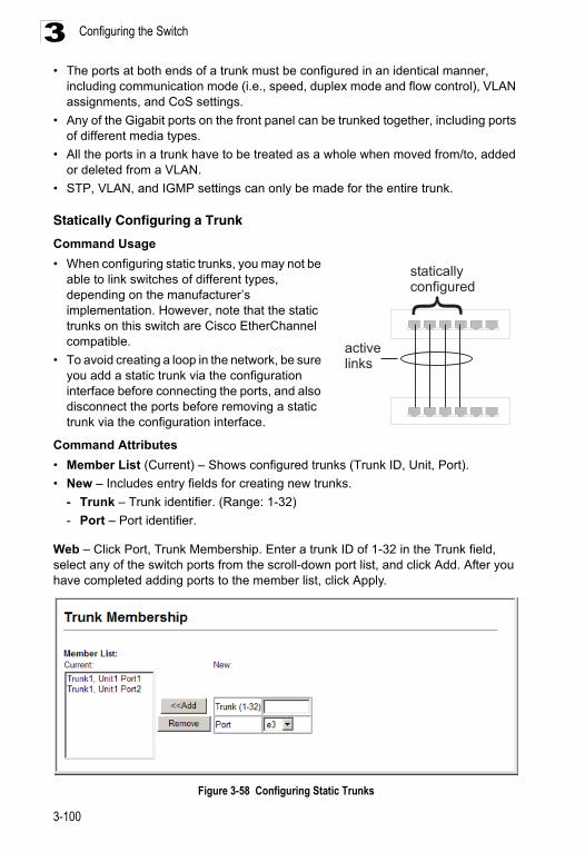
Configuring the Switch3
• The ports at both ends of a trunk must be configured in an identical manner,including communication mode (i.e., speed, duplex mode and flow control), VLAN assignments, and CoS settings.
• Any of the Gigabit ports on the front panel can be trunked together, including ports of different media types.
• All the ports in a trunk have to be treated as a whole when moved from/to, added or deleted from a VLAN.
• STP, VLAN, and IGMP settings can only be made for the entire trunk.
Statically Configuring a Trunk
Command Usage
• When configuring static trunks, you may not be able to link switches of different types, depending on the manufacturer’s implementation. However, note that the static trunks on this switch are Cisco EtherChannel compatible.
• To avoid creating a loop in the network, be sure you add a static trunk via the configuration interface before connecting the ports, and also disconnect the ports before removing a static trunk via the configuration interface.
Command Attributes
• Member List (Current) – Shows configured trunks (Trunk ID, Unit, Port).
• New – Includes entry fields for creating new trunks.
- Trunk – Trunk identifier. (Range: 1-32)
- Port – Port identifier.
Web – Click Port, Trunk Membership. Enter a trunk ID of 1-32 in the Trunk field, select any of the switch ports from the scroll-down port list, and click Add. After you have completed adding ports to the member list, click Apply.
Figure 3-58 Configuring Static Trunks
activelinks
}
staticallyconfigured
3-100
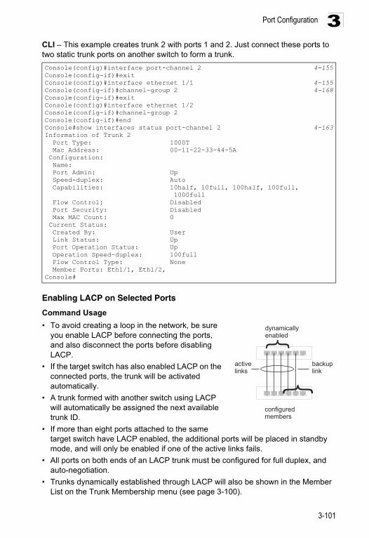
Port Configuration 3
CLI – This example creates trunk 2 with ports 1 and 2. Just connect these ports to two static trunk ports on another switch to form a trunk.Enabling LACP on Selected Ports
Command Usage
• To avoid creating a loop in the network, be sure you enable LACP before connecting the ports, and also disconnect the ports before disabling LACP.
• If the target switch has also enabled LACP on the connected ports, the trunk will be activated automatically.
• A trunk formed with another switch using LACP will automatically be assigned the next available trunk ID.
• If more than eight ports attached to the same target switch have LACP enabled, the additional ports will be placed in standby mode, and will only be enabled if one of the active links fails.
• All ports on both ends of an LACP trunk must be configured for full duplex, and auto-negotiation.
• Trunks dynamically established through LACP will also be shown in the Member List on the Trunk Membership menu (see page 3-100).
Console(config)#interface port-channel 2 4-155Console(config-if)#exitConsole(config)#interface ethernet 1/1 4-155Console(config-if)#channel-group 2 4-168Console(config-if)#exitConsole(config)#interface ethernet 1/2Console(config-if)#channel-group 2Console(config-if)#endConsole#show interfaces status port-channel 2 4-163Information of Trunk 2 Port Type: 1000T Mac Address: 00-11-22-33-44-5A Configuration: Name: Port Admin: Up Speed-duplex: Auto Capabilities: 10half, 10full, 100half, 100full, 1000full Flow Control: Disabled Port Security: Disabled Max MAC Count: 0 Current Status: Created By: User Link Status: Up Port Operation Status: Up Operation Speed-duplex: 100full Flow Control Type: None Member Ports: Eth1/1, Eth1/2,Console#
activelinks
}
}
dynamicallyenabled
configuredmembers
backuplink
3-101
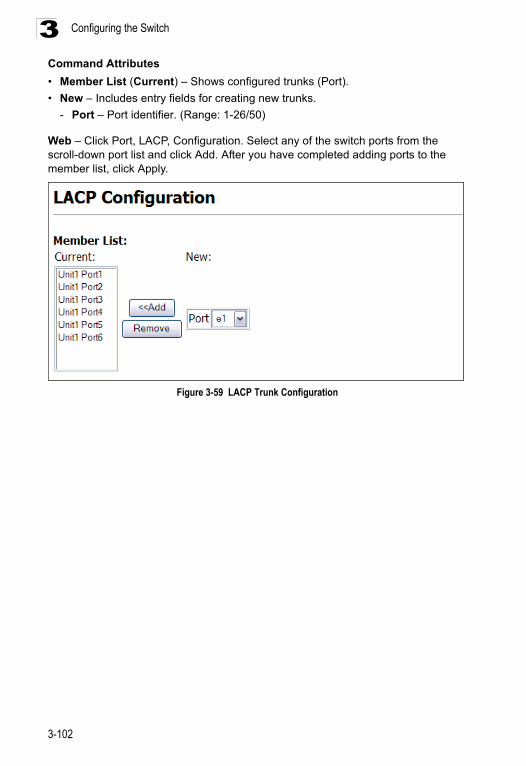
Configuring the Switch3
Command Attributes• Member List (Current) – Shows configured trunks (Port).
• New – Includes entry fields for creating new trunks.
- Port – Port identifier. (Range: 1-26/50)
Web – Click Port, LACP, Configuration. Select any of the switch ports from the scroll-down port list and click Add. After you have completed adding ports to the member list, click Apply.
Figure 3-59 LACP Trunk Configuration
3-102
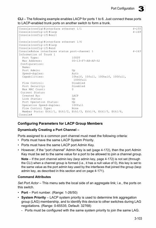
Port Configuration 3
CLI – The following example enables LACP for ports 1 to 6. Just connect these ports to LACP-enabled trunk ports on another switch to form a trunk.Configuring Parameters for LACP Group Members
Dynamically Creating a Port Channel –
Ports assigned to a common port channel must meet the following criteria:• Ports must have the same LACP System Priority.
• Ports must have the same LACP port Admin Key.
• However, if the “port channel” Admin Key is set (page 4-172), then the port Admin Key must be set to the same value for a port to be allowed to join a channel group.
Note – If the port channel admin key (lacp admin key, page 4-172) is not set (through the CLI) when a channel group is formed (i.e., it has a null value of 0), this key is set to the same value as the port admin key used by the interfaces that joined the group (lacp admin key, as described in this section and on page 4-171).
Command Attributes
Set Port Actor – This menu sets the local side of an aggregate link; i.e., the ports on this switch.
• Port – Port number. (Range: 1-26/50)
• System Priority – LACP system priority is used to determine link aggregation group (LAG) membership, and to identify this device to other switches during LAG negotiations. (Range: 0-65535; Default: 32768)- Ports must be configured with the same system priority to join the same LAG.
Console(config)#interface ethernet 1/1 4-155Console(config-if)#lacp 4-169Console(config-if)#exit...Console(config)#interface ethernet 1/6Console(config-if)#lacpConsole(config-if)#endConsole#show interfaces status port-channel 1 4-163Information of Trunk 1 Port Type: 1000T Mac Address: 00-13-F7-A8-AF-52 Configuration: Name: Port Admin: Up Speed-duplex: Auto Capabilities: 10half, 10full, 100half, 100full, 1000full Flow Control: Disabled Port Security: Disabled Max MAC Count: 0 Current Status: Created By: LACP Link Status: Up Port Operation Status: Up Operation Speed-duplex: 100full Flow Control Type: None Member Ports: Eth1/1, Eth1/2, Eth1/3, Eth1/4, Eth1/5, Eth1/6,Console#
3-103
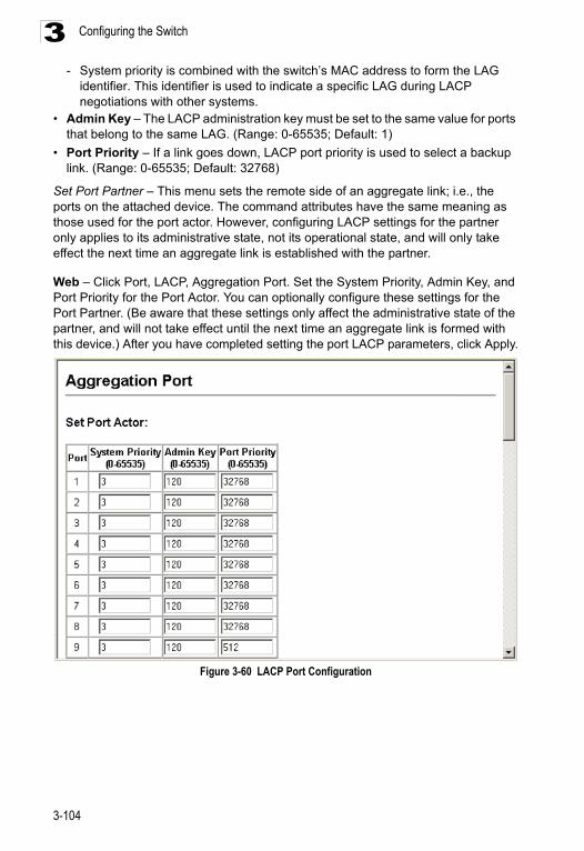
Configuring the Switch3
- System priority is combined with the switch’s MAC address to form the LAGidentifier. This identifier is used to indicate a specific LAG during LACP negotiations with other systems.
• Admin Key – The LACP administration key must be set to the same value for ports that belong to the same LAG. (Range: 0-65535; Default: 1)
• Port Priority – If a link goes down, LACP port priority is used to select a backup link. (Range: 0-65535; Default: 32768)
Set Port Partner – This menu sets the remote side of an aggregate link; i.e., the ports on the attached device. The command attributes have the same meaning as those used for the port actor. However, configuring LACP settings for the partner only applies to its administrative state, not its operational state, and will only take effect the next time an aggregate link is established with the partner.
Web – Click Port, LACP, Aggregation Port. Set the System Priority, Admin Key, and Port Priority for the Port Actor. You can optionally configure these settings for the Port Partner. (Be aware that these settings only affect the administrative state of the partner, and will not take effect until the next time an aggregate link is formed with this device.) After you have completed setting the port LACP parameters, click Apply.
Figure 3-60 LACP Port Configuration
3-104
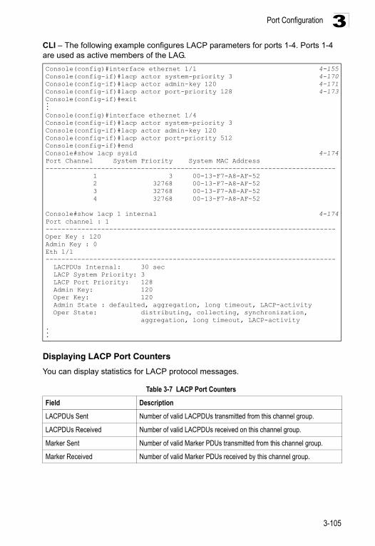
Port Configuration 3
CLI – The following example configures LACP parameters for ports 1-4. Ports 1-4 are used as active members of the LAG.Displaying LACP Port Counters
You can display statistics for LACP protocol messages.
Console(config)#interface ethernet 1/1 4-155Console(config-if)#lacp actor system-priority 3 4-170Console(config-if)#lacp actor admin-key 120 4-171Console(config-if)#lacp actor port-priority 128 4-173Console(config-if)#exit...Console(config)#interface ethernet 1/4Console(config-if)#lacp actor system-priority 3Console(config-if)#lacp actor admin-key 120Console(config-if)#lacp actor port-priority 512Console(config-if)#endConsole#show lacp sysid 4-174Port Channel System Priority System MAC Address------------------------------------------------------------------------- 1 3 00-13-F7-A8-AF-52 2 32768 00-13-F7-A8-AF-52 3 32768 00-13-F7-A8-AF-52 4 32768 00-13-F7-A8-AF-52
Console#show lacp 1 internal 4-174Port channel : 1-------------------------------------------------------------------------Oper Key : 120Admin Key : 0Eth 1/1------------------------------------------------------------------------- LACPDUs Internal: 30 sec LACP System Priority: 3 LACP Port Priority: 128 Admin Key: 120 Oper Key: 120 Admin State : defaulted, aggregation, long timeout, LACP-activity Oper State: distributing, collecting, synchronization, aggregation, long timeout, LACP-activity...
Table 3-7 LACP Port Counters
Field Description
LACPDUs Sent Number of valid LACPDUs transmitted from this channel group.
LACPDUs Received Number of valid LACPDUs received on this channel group.
Marker Sent Number of valid Marker PDUs transmitted from this channel group.
Marker Received Number of valid Marker PDUs received by this channel group.
3-105
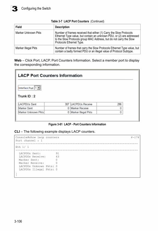
Configuring the Switch3
Web – Click Port, LACP, Port Counters Information. Select a member port to display the corresponding information.
Figure 3-61 LACP - Port Counters Information
CLI – The following example displays LACP counters.
Marker Unknown Pkts Number of frames received that either (1) Carry the Slow Protocols Ethernet Type value, but contain an unknown PDU, or (2) are addressed to the Slow Protocols group MAC Address, but do not carry the Slow Protocols Ethernet Type.
Marker Illegal Pkts Number of frames that carry the Slow Protocols Ethernet Type value, but contain a badly formed PDU or an illegal value of Protocol Subtype.
Console#show lacp counters 4-174Port channel : 1 -------------------------------------------------------------------------Eth 1/ 1 ------------------------------------------------------------------------- LACPDUs Sent: 91 LACPDUs Receive: 43 Marker Sent: 0 Marker Receive: 0 LACPDUs Unknown Pkts: 0 LACPDUs Illegal Pkts: 0...
Table 3-7 LACP Port Counters (Continued)
Field Description
3-106
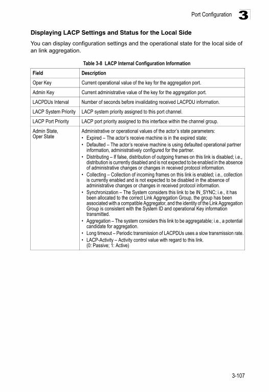
Port Configuration 3
Displaying LACP Settings and Status for the Local SideYou can display configuration settings and the operational state for the local side of an link aggregation.
Table 3-8 LACP Internal Configuration Information
Field Description
Oper Key Current operational value of the key for the aggregation port.
Admin Key Current administrative value of the key for the aggregation port.
LACPDUs Interval Number of seconds before invalidating received LACPDU information.
LACP System Priority LACP system priority assigned to this port channel.
LACP Port Priority LACP port priority assigned to this interface within the channel group.
Admin State,Oper State
Administrative or operational values of the actor’s state parameters:• Expired – The actor’s receive machine is in the expired state;• Defaulted – The actor’s receive machine is using defaulted operational partner
information, administratively configured for the partner.• Distributing – If false, distribution of outgoing frames on this link is disabled; i.e.,
distribution is currently disabled and is not expected to be enabled in the absence of administrative changes or changes in received protocol information.
• Collecting – Collection of incoming frames on this link is enabled; i.e., collection is currently enabled and is not expected to be disabled in the absence of administrative changes or changes in received protocol information.
• Synchronization – The System considers this link to be IN_SYNC; i.e., it has been allocated to the correct Link Aggregation Group, the group has been associated with a compatible Aggregator, and the identity of the Link Aggregation Group is consistent with the System ID and operational Key information transmitted.
• Aggregation – The system considers this link to be aggregatable; i.e., a potential candidate for aggregation.
• Long timeout – Periodic transmission of LACPDUs uses a slow transmission rate.• LACP-Activity – Activity control value with regard to this link.
(0: Passive; 1: Active)
3-107
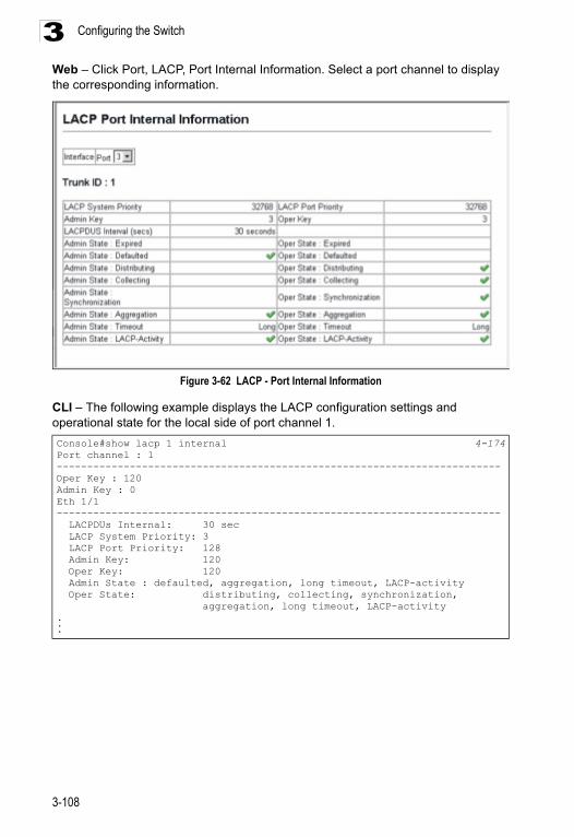
Configuring the Switch3
Web – Click Port, LACP, Port Internal Information. Select a port channel to display the corresponding information.Figure 3-62 LACP - Port Internal Information
CLI – The following example displays the LACP configuration settings and operational state for the local side of port channel 1.
Console#show lacp 1 internal 4-174Port channel : 1-------------------------------------------------------------------------Oper Key : 120Admin Key : 0Eth 1/1------------------------------------------------------------------------- LACPDUs Internal: 30 sec LACP System Priority: 3 LACP Port Priority: 128 Admin Key: 120 Oper Key: 120 Admin State : defaulted, aggregation, long timeout, LACP-activity Oper State: distributing, collecting, synchronization, aggregation, long timeout, LACP-activity...
3-108
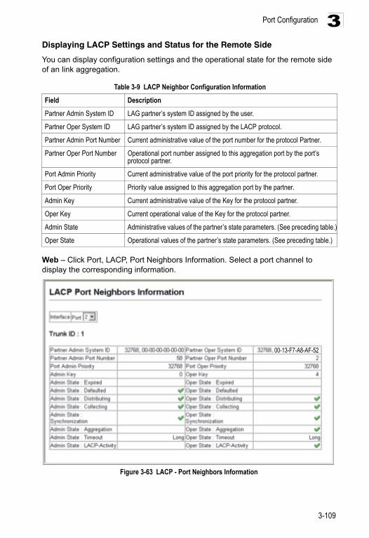
Port Configuration 3
Displaying LACP Settings and Status for the Remote SideYou can display configuration settings and the operational state for the remote side of an link aggregation.
Web – Click Port, LACP, Port Neighbors Information. Select a port channel to display the corresponding information.
Figure 3-63 LACP - Port Neighbors Information
Table 3-9 LACP Neighbor Configuration Information
Field Description
Partner Admin System ID LAG partner’s system ID assigned by the user.
Partner Oper System ID LAG partner’s system ID assigned by the LACP protocol.
Partner Admin Port Number Current administrative value of the port number for the protocol Partner.
Partner Oper Port Number Operational port number assigned to this aggregation port by the port’s protocol partner.
Port Admin Priority Current administrative value of the port priority for the protocol partner.
Port Oper Priority Priority value assigned to this aggregation port by the partner.
Admin Key Current administrative value of the Key for the protocol partner.
Oper Key Current operational value of the Key for the protocol partner.
Admin State Administrative values of the partner’s state parameters. (See preceding table.)
Oper State Operational values of the partner’s state parameters. (See preceding table.)
00-13-F7-A8-AF-52
3-109
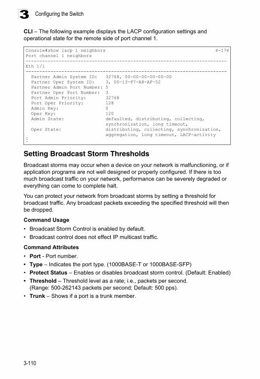
Configuring the Switch3
CLI – The following example displays the LACP configuration settings and operational state for the remote side of port channel 1.Setting Broadcast Storm ThresholdsBroadcast storms may occur when a device on your network is malfunctioning, or if application programs are not well designed or properly configured. If there is too much broadcast traffic on your network, performance can be severely degraded or everything can come to complete halt.
You can protect your network from broadcast storms by setting a threshold for broadcast traffic. Any broadcast packets exceeding the specified threshold will then be dropped.
Command Usage
• Broadcast Storm Control is enabled by default.
• Broadcast control does not effect IP multicast traffic.
Command Attributes
• Port - Port number.
• Type – Indicates the port type. (1000BASE-T or 1000BASE-SFP)
• Protect Status – Enables or disables broadcast storm control. (Default: Enabled)
• Threshold – Threshold level as a rate; i.e., packets per second. (Range: 500-262143 packets per second; Default: 500 pps).
• Trunk – Shows if a port is a trunk member.
Console#show lacp 1 neighbors 4-174Port channel 1 neighbors-------------------------------------------------------------------------Eth 1/1------------------------------------------------------------------------- Partner Admin System ID: 32768, 00-00-00-00-00-00 Partner Oper System ID: 3, 00-13-F7-A8-AF-52 Partner Admin Port Number: 5 Partner Oper Port Number: 3 Port Admin Priority: 32768 Port Oper Priority: 128 Admin Key: 0 Oper Key: 120 Admin State: defaulted, distributing, collecting, synchronization, long timeout, Oper State: distributing, collecting, synchronization, aggregation, long timeout, LACP-activity...
3-110
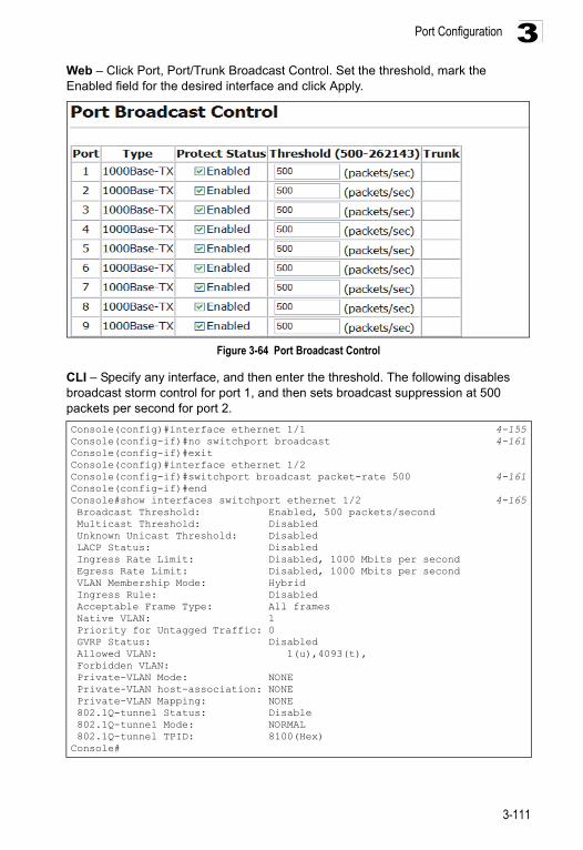
Port Configuration 3
Web – Click Port, Port/Trunk Broadcast Control. Set the threshold, mark the Enabled field for the desired interface and click Apply.Figure 3-64 Port Broadcast Control
CLI – Specify any interface, and then enter the threshold. The following disables broadcast storm control for port 1, and then sets broadcast suppression at 500 packets per second for port 2.
Console(config)#interface ethernet 1/1 4-155Console(config-if)#no switchport broadcast 4-161Console(config-if)#exitConsole(config)#interface ethernet 1/2Console(config-if)#switchport broadcast packet-rate 500 4-161Console(config-if)#endConsole#show interfaces switchport ethernet 1/2 4-165 Broadcast Threshold: Enabled, 500 packets/second Multicast Threshold: Disabled Unknown Unicast Threshold: Disabled LACP Status: Disabled Ingress Rate Limit: Disabled, 1000 Mbits per second Egress Rate Limit: Disabled, 1000 Mbits per second VLAN Membership Mode: Hybrid Ingress Rule: Disabled Acceptable Frame Type: All frames Native VLAN: 1 Priority for Untagged Traffic: 0 GVRP Status: Disabled Allowed VLAN: 1(u),4093(t), Forbidden VLAN: Private-VLAN Mode: NONE Private-VLAN host-association: NONE Private-VLAN Mapping: NONE 802.1Q-tunnel Status: Disable 802.1Q-tunnel Mode: NORMAL 802.1Q-tunnel TPID: 8100(Hex)Console#
3-111
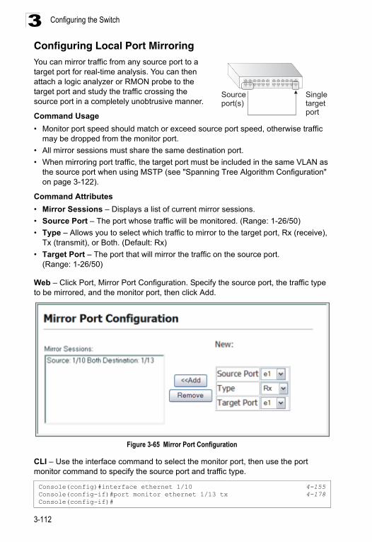
Configuring the Switch3
Configuring Local Port MirroringYou can mirror traffic from any source port to a target port for real-time analysis. You can then attach a logic analyzer or RMON probe to the target port and study the traffic crossing the source port in a completely unobtrusive manner.Command Usage
• Monitor port speed should match or exceed source port speed, otherwise traffic may be dropped from the monitor port.
• All mirror sessions must share the same destination port.
• When mirroring port traffic, the target port must be included in the same VLAN as the source port when using MSTP (see "Spanning Tree Algorithm Configuration" on page 3-122).
Command Attributes
• Mirror Sessions – Displays a list of current mirror sessions.
• Source Port – The port whose traffic will be monitored. (Range: 1-26/50)
• Type – Allows you to select which traffic to mirror to the target port, Rx (receive), Tx (transmit), or Both. (Default: Rx)
• Target Port – The port that will mirror the traffic on the source port. (Range: 1-26/50)
Web – Click Port, Mirror Port Configuration. Specify the source port, the traffic type to be mirrored, and the monitor port, then click Add.
Figure 3-65 Mirror Port Configuration
CLI – Use the interface command to select the monitor port, then use the port monitor command to specify the source port and traffic type.
Console(config)#interface ethernet 1/10 4-155Console(config-if)#port monitor ethernet 1/13 tx 4-178Console(config-if)#
Sourceport(s)
Singletargetport
3-112
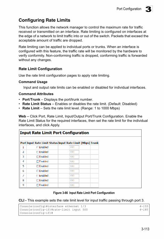
Port Configuration 3
Configuring Rate LimitsThis function allows the network manager to control the maximum rate for traffic received or transmitted on an interface. Rate limiting is configured on interfaces at the edge of a network to limit traffic into or out of the switch. Packets that exceed the acceptable amount of traffic are dropped.Rate limiting can be applied to individual ports or trunks. When an interface is configured with this feature, the traffic rate will be monitored by the hardware to verify conformity. Non-conforming traffic is dropped, conforming traffic is forwarded without any changes.
Rate Limit Configuration
Use the rate limit configuration pages to apply rate limiting.
Command Usage
Input and output rate limits can be enabled or disabled for individual interfaces.
Command Attributes
• Port/Trunk – Displays the port/trunk number.• Rate Limit Status – Enables or disables the rate limit. (Default: Disabled)• Rate Limit – Sets the rate limit level. (Range: 1 to 1000 Mbps)
Web – Click Port, Rate Limit, Input/Output Port/Trunk Configuration. Enable the Rate Limit Status for the required interfaces, then set the rate limit for the individual interfaces, and click Apply.
Figure 3-66 Input Rate Limit Port Configuration
CLI - This example sets the rate limit level for input traffic passing through port 3.
Console(config)#interface ethernet 1/3 4-155Console(config-if)#rate-limit input 500 4-185Console(config-if)#
3-113
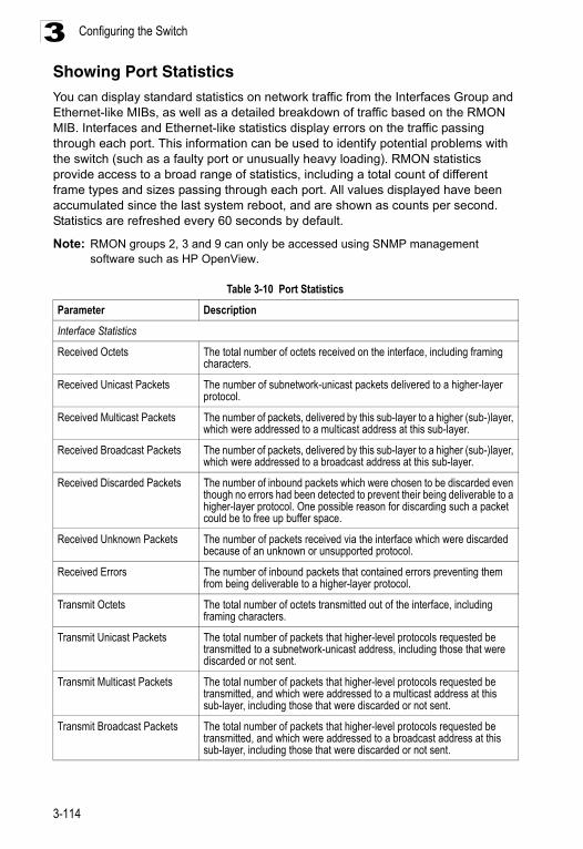
Configuring the Switch3
Showing Port StatisticsYou can display standard statistics on network traffic from the Interfaces Group and Ethernet-like MIBs, as well as a detailed breakdown of traffic based on the RMON MIB. Interfaces and Ethernet-like statistics display errors on the traffic passing through each port. This information can be used to identify potential problems with the switch (such as a faulty port or unusually heavy loading). RMON statistics provide access to a broad range of statistics, including a total count of different frame types and sizes passing through each port. All values displayed have been accumulated since the last system reboot, and are shown as counts per second. Statistics are refreshed every 60 seconds by default.Note: RMON groups 2, 3 and 9 can only be accessed using SNMP management software such as HP OpenView.
Table 3-10 Port Statistics
Parameter Description
Interface Statistics
Received Octets The total number of octets received on the interface, including framing characters.
Received Unicast Packets The number of subnetwork-unicast packets delivered to a higher-layer protocol.
Received Multicast Packets The number of packets, delivered by this sub-layer to a higher (sub-)layer, which were addressed to a multicast address at this sub-layer.
Received Broadcast Packets The number of packets, delivered by this sub-layer to a higher (sub-)layer, which were addressed to a broadcast address at this sub-layer.
Received Discarded Packets The number of inbound packets which were chosen to be discarded even though no errors had been detected to prevent their being deliverable to a higher-layer protocol. One possible reason for discarding such a packet could be to free up buffer space.
Received Unknown Packets The number of packets received via the interface which were discarded because of an unknown or unsupported protocol.
Received Errors The number of inbound packets that contained errors preventing them from being deliverable to a higher-layer protocol.
Transmit Octets The total number of octets transmitted out of the interface, including framing characters.
Transmit Unicast Packets The total number of packets that higher-level protocols requested be transmitted to a subnetwork-unicast address, including those that were discarded or not sent.
Transmit Multicast Packets The total number of packets that higher-level protocols requested be transmitted, and which were addressed to a multicast address at this sub-layer, including those that were discarded or not sent.
Transmit Broadcast Packets The total number of packets that higher-level protocols requested be transmitted, and which were addressed to a broadcast address at this sub-layer, including those that were discarded or not sent.
3-114
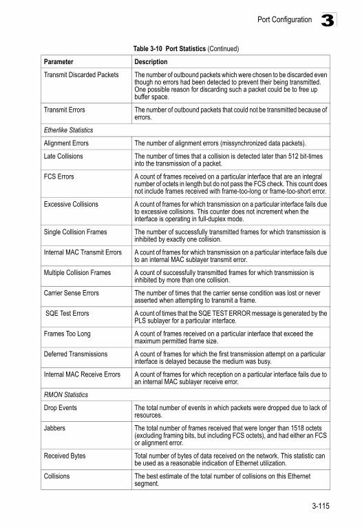
Port Configuration 3
Transmit Discarded Packets The number of outbound packets which were chosen to be discarded even though no errors had been detected to prevent their being transmitted. One possible reason for discarding such a packet could be to free up buffer space.
Transmit Errors The number of outbound packets that could not be transmitted because of errors.
Etherlike Statistics
Alignment Errors The number of alignment errors (missynchronized data packets).
Late Collisions The number of times that a collision is detected later than 512 bit-times into the transmission of a packet.
FCS Errors A count of frames received on a particular interface that are an integral number of octets in length but do not pass the FCS check. This count does not include frames received with frame-too-long or frame-too-short error.
Excessive Collisions A count of frames for which transmission on a particular interface fails due to excessive collisions. This counter does not increment when the interface is operating in full-duplex mode.
Single Collision Frames The number of successfully transmitted frames for which transmission is inhibited by exactly one collision.
Internal MAC Transmit Errors A count of frames for which transmission on a particular interface fails due to an internal MAC sublayer transmit error.
Multiple Collision Frames A count of successfully transmitted frames for which transmission is inhibited by more than one collision.
Carrier Sense Errors The number of times that the carrier sense condition was lost or never asserted when attempting to transmit a frame.
SQE Test Errors A count of times that the SQE TEST ERROR message is generated by the PLS sublayer for a particular interface.
Frames Too Long A count of frames received on a particular interface that exceed the maximum permitted frame size.
Deferred Transmissions A count of frames for which the first transmission attempt on a particular interface is delayed because the medium was busy.
Internal MAC Receive Errors A count of frames for which reception on a particular interface fails due to an internal MAC sublayer receive error.
RMON Statistics
Drop Events The total number of events in which packets were dropped due to lack of resources.
Jabbers The total number of frames received that were longer than 1518 octets (excluding framing bits, but including FCS octets), and had either an FCS or alignment error.
Received Bytes Total number of bytes of data received on the network. This statistic can be used as a reasonable indication of Ethernet utilization.
Collisions The best estimate of the total number of collisions on this Ethernet segment.
Table 3-10 Port Statistics (Continued)
Parameter Description
3-115
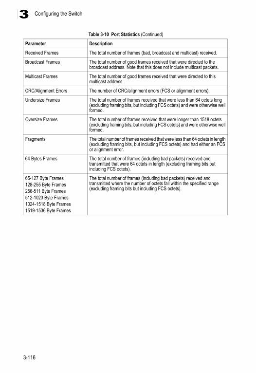
Configuring the Switch3
Received Frames The total number of frames (bad, broadcast and multicast) received.
Broadcast Frames The total number of good frames received that were directed to the broadcast address. Note that this does not include multicast packets.
Multicast Frames The total number of good frames received that were directed to this multicast address.
CRC/Alignment Errors The number of CRC/alignment errors (FCS or alignment errors).
Undersize Frames The total number of frames received that were less than 64 octets long (excluding framing bits, but including FCS octets) and were otherwise well formed.
Oversize Frames The total number of frames received that were longer than 1518 octets (excluding framing bits, but including FCS octets) and were otherwise well formed.
Fragments The total number of frames received that were less than 64 octets in length (excluding framing bits, but including FCS octets) and had either an FCS or alignment error.
64 Bytes Frames The total number of frames (including bad packets) received and transmitted that were 64 octets in length (excluding framing bits but including FCS octets).
65-127 Byte Frames128-255 Byte Frames256-511 Byte Frames512-1023 Byte Frames1024-1518 Byte Frames1519-1536 Byte Frames
The total number of frames (including bad packets) received and transmitted where the number of octets fall within the specified range (excluding framing bits but including FCS octets).
Table 3-10 Port Statistics (Continued)
Parameter Description
3-116
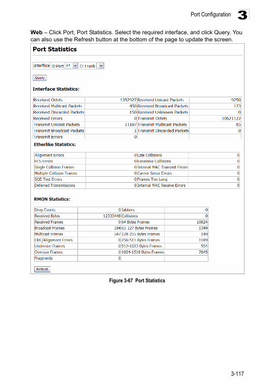
Port Configuration 3
Web – Click Port, Port Statistics. Select the required interface, and click Query. You can also use the Refresh button at the bottom of the page to update the screen.Figure 3-67 Port Statistics
3-117
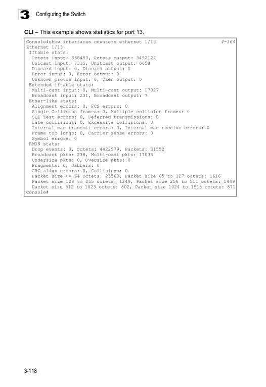
Configuring the Switch3
CLI – This example shows statistics for port 13.Console#show interfaces counters ethernet 1/13 4-164Ethernet 1/13 Iftable stats: Octets input: 868453, Octets output: 3492122 Unicast input: 7315, Unitcast output: 6658 Discard input: 0, Discard output: 0 Error input: 0, Error output: 0 Unknown protos input: 0, QLen output: 0 Extended iftable stats: Multi-cast input: 0, Multi-cast output: 17027 Broadcast input: 231, Broadcast output: 7 Ether-like stats: Alignment errors: 0, FCS errors: 0 Single Collision frames: 0, Multiple collision frames: 0 SQE Test errors: 0, Deferred transmissions: 0 Late collisions: 0, Excessive collisions: 0 Internal mac transmit errors: 0, Internal mac receive errors: 0 Frame too longs: 0, Carrier sense errors: 0 Symbol errors: 0 RMON stats: Drop events: 0, Octets: 4422579, Packets: 31552 Broadcast pkts: 238, Multi-cast pkts: 17033 Undersize pkts: 0, Oversize pkts: 0 Fragments: 0, Jabbers: 0 CRC align errors: 0, Collisions: 0 Packet size <= 64 octets: 25568, Packet size 65 to 127 octets: 1616 Packet size 128 to 255 octets: 1249, Packet size 256 to 511 octets: 1449 Packet size 512 to 1023 octets: 802, Packet size 1024 to 1518 octets: 871Console#
3-118
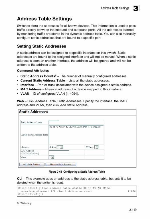
Address Table Settings 3
Address Table SettingsSwitches store the addresses for all known devices. This information is used to pass traffic directly between the inbound and outbound ports. All the addresses learned by monitoring traffic are stored in the dynamic address table. You can also manually configure static addresses that are bound to a specific port.Setting Static AddressesA static address can be assigned to a specific interface on this switch. Static addresses are bound to the assigned interface and will not be moved. When a static address is seen on another interface, the address will be ignored and will not be written to the address table.
Command Attributes
• Static Address Counts8 – The number of manually configured addresses.• Current Static Address Table – Lists all the static addresses.• Interface – Port or trunk associated with the device assigned a static address.• MAC Address – Physical address of a device mapped to this interface.• VLAN – ID of configured VLAN (1-4094).
Web – Click Address Table, Static Addresses. Specify the interface, the MAC address and VLAN, then click Add Static Address.
Figure 3-68 Configuring a Static Address Table
CLI – This example adds an address to the static address table, but sets it to be deleted when the switch is reset.
8. Web only.
Console(config)#mac-address-table static 00-13-F7-A8-AF-52 interface ethernet 1/1 vlan 1 delete-on-reset 4-186
Console(config)#
00-13-F7-A8-AF-52
3-119
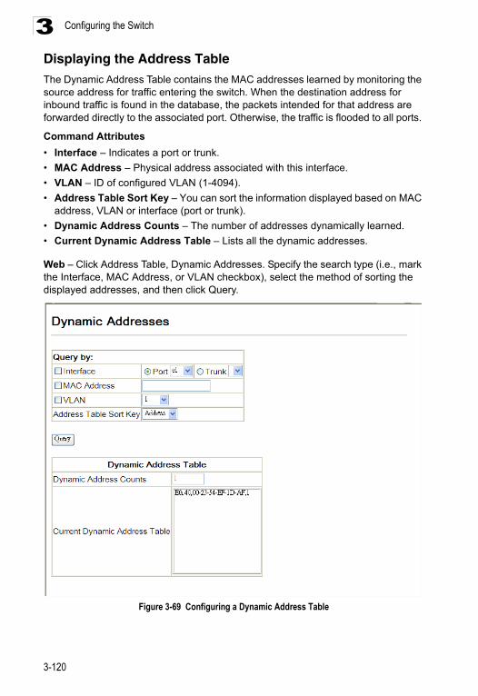
Configuring the Switch3
Displaying the Address TableThe Dynamic Address Table contains the MAC addresses learned by monitoring the source address for traffic entering the switch. When the destination address for inbound traffic is found in the database, the packets intended for that address are forwarded directly to the associated port. Otherwise, the traffic is flooded to all ports.Command Attributes
• Interface – Indicates a port or trunk.
• MAC Address – Physical address associated with this interface.
• VLAN – ID of configured VLAN (1-4094).
• Address Table Sort Key – You can sort the information displayed based on MAC address, VLAN or interface (port or trunk).
• Dynamic Address Counts – The number of addresses dynamically learned.
• Current Dynamic Address Table – Lists all the dynamic addresses.
Web – Click Address Table, Dynamic Addresses. Specify the search type (i.e., mark the Interface, MAC Address, or VLAN checkbox), select the method of sorting the displayed addresses, and then click Query.
Figure 3-69 Configuring a Dynamic Address Table
3-120
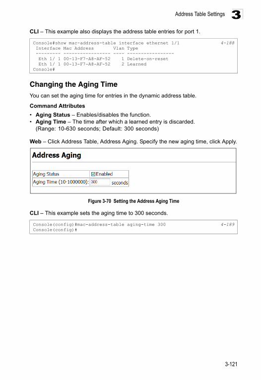
Address Table Settings 3
CLI – This example also displays the address table entries for port 1.Changing the Aging TimeYou can set the aging time for entries in the dynamic address table.
Command Attributes
• Aging Status – Enables/disables the function.• Aging Time – The time after which a learned entry is discarded.
(Range: 10-630 seconds; Default: 300 seconds)
Web – Click Address Table, Address Aging. Specify the new aging time, click Apply.
Figure 3-70 Setting the Address Aging Time
CLI – This example sets the aging time to 300 seconds.
Console#show mac-address-table interface ethernet 1/1 4-188 Interface Mac Address Vlan Type --------- ----------------- ---- ----------------- Eth 1/ 1 00-13-F7-A8-AF-52 1 Delete-on-reset Eth 1/ 1 00-13-F7-A8-AF-52 2 LearnedConsole#
Console(config)#mac-address-table aging-time 300 4-189Console(config)#
3-121

Configuring the Switch3
Spanning Tree Algorithm Configuration The Spanning Tree Algorithm (STA) can be used to detect and disable network loops, and to provide backup links between switches, bridges or routers. This allows the switch to interact with other bridging devices (that is, an STA-compliant switch, bridge or router) in your network to ensure that only one route exists between any two stations on the network, and provide backup links which automatically take over when a primary link goes down.The spanning tree algorithms supported by this switch include these versions:• STP – Spanning Tree Protocol (IEEE 802.1D)• RSTP – Rapid Spanning Tree Protocol (IEEE 802.1w)• MSTP – Multiple Spanning Tree Protocol (IEEE 802.1s)
STP – STP uses a distributed algorithm to select a bridging device (STP-compliant switch, bridge or router) that serves as the root of the spanning tree network. It selects a root port on each bridging device (except for the root device) which incurs the lowest path cost when forwarding a packet from that device to the root device. Then it selects a designated bridging device from each LAN which incurs the lowest path cost when forwarding a packet from that LAN to the root device. All ports connected to designated bridging devices are assigned as designated ports. After determining the lowest cost spanning tree, it enables all root ports and designated ports, and disables all other ports. Network packets are therefore only forwarded between root ports and designated ports, eliminating any possible network loops.
Once a stable network topology has been established, all bridges listen for Hello BPDUs (Bridge Protocol Data Units) transmitted from the Root Bridge. If a bridge does not get a Hello BPDU after a predefined interval (Maximum Age), the bridge assumes that the link to the Root Bridge is down. This bridge will then initiate negotiations with other bridges to reconfigure the network to reestablish a valid network topology.
RSTP – RSTP is designed as a general replacement for the slower, legacy STP. RSTP is also incorporated into MSTP. RSTP achieves must faster reconfiguration (i.e., around 1 to 3 seconds, compared to 30 seconds or more for STP) by reducing the number of state changes before active ports start learning, predefining an alternate route that can be used when a node or port fails, and retaining the forwarding database for ports insensitive to changes in the tree structure when reconfiguration occurs.
3-122
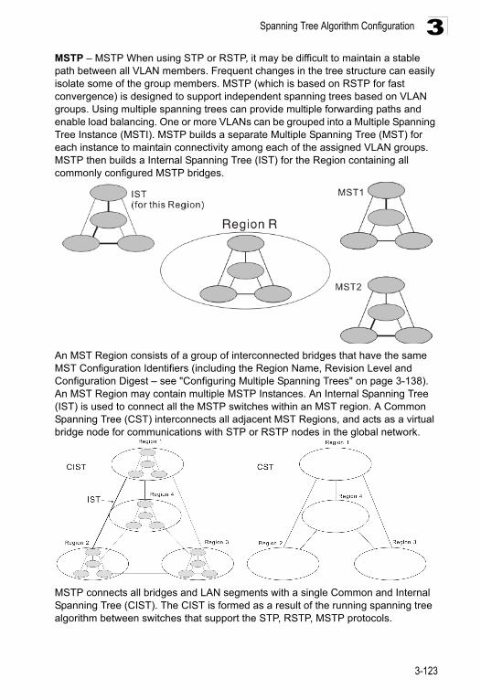
Spanning Tree Algorithm Configuration 3
MSTP – MSTP When using STP or RSTP, it may be difficult to maintain a stable path between all VLAN members. Frequent changes in the tree structure can easily isolate some of the group members. MSTP (which is based on RSTP for fast convergence) is designed to support independent spanning trees based on VLAN groups. Using multiple spanning trees can provide multiple forwarding paths and enable load balancing. One or more VLANs can be grouped into a Multiple Spanning Tree Instance (MSTI). MSTP builds a separate Multiple Spanning Tree (MST) for each instance to maintain connectivity among each of the assigned VLAN groups. MSTP then builds a Internal Spanning Tree (IST) for the Region containing all commonly configured MSTP bridges.An MST Region consists of a group of interconnected bridges that have the same MST Configuration Identifiers (including the Region Name, Revision Level and Configuration Digest – see "Configuring Multiple Spanning Trees" on page 3-138). An MST Region may contain multiple MSTP Instances. An Internal Spanning Tree (IST) is used to connect all the MSTP switches within an MST region. A Common Spanning Tree (CST) interconnects all adjacent MST Regions, and acts as a virtual bridge node for communications with STP or RSTP nodes in the global network.
MSTP connects all bridges and LAN segments with a single Common and Internal Spanning Tree (CIST). The CIST is formed as a result of the running spanning tree algorithm between switches that support the STP, RSTP, MSTP protocols.
3-123
Configuring the Switch3
Once you specify the VLANs to include in a Multiple Spanning Tree Instance (MSTI), the protocol will automatically build an MSTI tree to maintain connectivity among each of the VLANs. MSTP maintains contact with the global network because each instance is treated as an RSTP node in the Common Spanning Tree (CST).Displaying Global Settings for STA
You can display a summary of the current bridge STA information that applies to the entire switch using the STA Information screen.
Field Attributes
• Spanning Tree State – Shows if the switch is enabled to participate in an STA-compliant network.
• Bridge ID – A unique identifier for this bridge, consisting of the bridge priority, the MST Instance ID 0 for the Common Spanning Tree when spanning tree mode is set to MSTP (page 3-127), and MAC address (where the address is taken from the switch system).
• Max Age – The maximum time (in seconds) a device can wait without receiving a configuration message before attempting to reconfigure. All device ports (except for designated ports) should receive configuration messages at regular intervals. Any port that ages out STA information (provided in the last configuration message) becomes the designated port for the attached LAN. If it is a root port, a new root port is selected from among the device ports attached to the network. (References to “ports” in this section mean “interfaces,” which includes both ports and trunks.)
• Hello Time – Interval (in seconds) at which the root device transmits a configuration message.
• Forward Delay – The maximum time (in seconds) the root device will wait before changing states (i.e., discarding to learning to forwarding). This delay is required because every device must receive information about topology changes before it starts to forward frames. In addition, each port needs time to listen for conflicting information that would make it return to a discarding state; otherwise, temporary data loops might result.
• Designated Root – The priority and MAC address of the device in the Spanning Tree that this switch has accepted as the root device.
- Root Port – The number of the port on this switch that is closest to the root. This switch communicates with the root device through this port. If there is no root port, then this switch has been accepted as the root device of the Spanning Tree network.
- Root Path Cost – The path cost from the root port on this switch to the root device.
• Configuration Changes – The number of times the Spanning Tree has been reconfigured.
• Last Topology Change – Time since the Spanning Tree was last reconfigured.
3-124
Spanning Tree Algorithm Configuration 3
These additional parameters are only displayed for the CLI:• Spanning tree mode – Specifies the type of spanning tree used on this switch:
- STP: Spanning Tree Protocol (IEEE 802.1D)- RSTP: Rapid Spanning Tree (IEEE 802.1w)- MSTP: Multiple Spanning Tree (IEEE 802.1s)
• Instance – Instance identifier of this spanning tree. (This is always 0 for the CIST.)
• VLANs Configuration – VLANs assigned to the CIST.
• Priority – Bridge priority is used in selecting the root device, root port, and designated port. The device with the highest priority becomes the STA root device. However, if all devices have the same priority, the device with the lowest MAC address will then become the root device.
• Root Hello Time – Interval (in seconds) at which this device transmits a configuration message.
• Root Maximum Age – The maximum time (in seconds) this device can wait without receiving a configuration message before attempting to reconfigure. All device ports (except for designated ports) should receive configuration messages at regular intervals. If the root port ages out STA information (provided in the last configuration message), a new root port is selected from among the device ports attached to the network. (References to “ports” in this section means “interfaces,” which includes both ports and trunks.)
• Root Forward Delay – The maximum time (in seconds) this device will wait before changing states (i.e., discarding to learning to forwarding). This delay is required because every device must receive information about topology changes before it starts to forward frames. In addition, each port needs time to listen for conflicting information that would make it return to a discarding state; otherwise, temporary data loops might result.
• Max Hops – The max number of hop counts for the MST region.
• Remaining Hops – The remaining number of hop counts for the MST instance.
• Transmission limit – The minimum interval between the transmission of consecutive RSTP/MSTP BPDUs.
• Path Cost Method – The path cost is used to determine the best path between devices. The path cost method is used to determine the range of values that can be assigned to each interface.
3-125
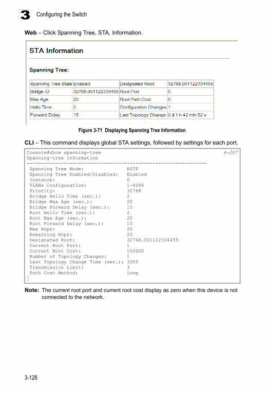
Configuring the Switch3
Web – Click Spanning Tree, STA, Information.Figure 3-71 Displaying Spanning Tree Information
CLI – This command displays global STA settings, followed by settings for each port.
Note: The current root port and current root cost display as zero when this device is not connected to the network.
Console#show spanning-tree 4-207Spanning-tree information--------------------------------------------------------------- Spanning Tree Mode: RSTP Spanning Tree Enabled/Disabled: Enabled Instance: 0 VLANs Configuration: 1-4094 Priority: 32768 Bridge Hello Time (sec.): 2 Bridge Max Age (sec.): 20 Bridge Forward Delay (sec.): 15 Root Hello Time (sec.): 2 Root Max Age (sec.): 20 Root Forward Delay (sec.): 15 Max Hops: 20 Remaining Hops: 20 Designated Root: 32768.001122334455 Current Root Port: 1 Current Root Cost: 100000 Number of Topology Changes: 1 Last Topology Change Time (sec.): 3305 Transmission Limit: 3 Path Cost Method: long...
3-126
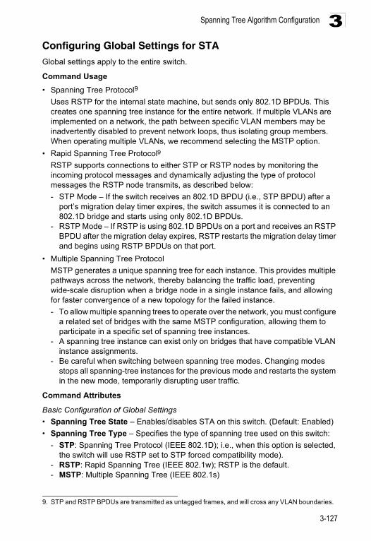
Spanning Tree Algorithm Configuration 3
Configuring Global Settings for STAGlobal settings apply to the entire switch.Command Usage
• Spanning Tree Protocol9
Uses RSTP for the internal state machine, but sends only 802.1D BPDUs. This creates one spanning tree instance for the entire network. If multiple VLANs are implemented on a network, the path between specific VLAN members may be inadvertently disabled to prevent network loops, thus isolating group members. When operating multiple VLANs, we recommend selecting the MSTP option.
• Rapid Spanning Tree Protocol9
RSTP supports connections to either STP or RSTP nodes by monitoring the incoming protocol messages and dynamically adjusting the type of protocol messages the RSTP node transmits, as described below:
- STP Mode – If the switch receives an 802.1D BPDU (i.e., STP BPDU) after a port’s migration delay timer expires, the switch assumes it is connected to an 802.1D bridge and starts using only 802.1D BPDUs.
- RSTP Mode – If RSTP is using 802.1D BPDUs on a port and receives an RSTP BPDU after the migration delay expires, RSTP restarts the migration delay timer and begins using RSTP BPDUs on that port.
• Multiple Spanning Tree Protocol
MSTP generates a unique spanning tree for each instance. This provides multiple pathways across the network, thereby balancing the traffic load, preventing wide-scale disruption when a bridge node in a single instance fails, and allowing for faster convergence of a new topology for the failed instance.
- To allow multiple spanning trees to operate over the network, you must configure a related set of bridges with the same MSTP configuration, allowing them to participate in a specific set of spanning tree instances.
- A spanning tree instance can exist only on bridges that have compatible VLAN instance assignments.
- Be careful when switching between spanning tree modes. Changing modes stops all spanning-tree instances for the previous mode and restarts the system in the new mode, temporarily disrupting user traffic.
Command Attributes
Basic Configuration of Global Settings
• Spanning Tree State – Enables/disables STA on this switch. (Default: Enabled)
• Spanning Tree Type – Specifies the type of spanning tree used on this switch:
- STP: Spanning Tree Protocol (IEEE 802.1D); i.e., when this option is selected, the switch will use RSTP set to STP forced compatibility mode).
- RSTP: Rapid Spanning Tree (IEEE 802.1w); RSTP is the default.- MSTP: Multiple Spanning Tree (IEEE 802.1s)
9. STP and RSTP BPDUs are transmitted as untagged frames, and will cross any VLAN boundaries.
3-127
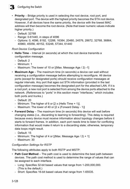
Configuring the Switch3
• Priority – Bridge priority is used in selecting the root device, root port, anddesignated port. The device with the highest priority becomes the STA root device. However, if all devices have the same priority, the device with the lowest MAC address will then become the root device. (Note that lower numeric values indicate higher priority.)
- Default: 32768- Range: 0-61440, in steps of 4096- Options: 0, 4096, 8192, 12288, 16384, 20480, 24576, 28672, 32768, 36864,
40960, 45056, 49152, 53248, 57344, 61440
Root Device Configuration
• Hello Time – Interval (in seconds) at which the root device transmits a configuration message.
- Default: 2- Minimum: 1- Maximum: The lower of 10 or [(Max. Message Age / 2) -1]
• Maximum Age – The maximum time (in seconds) a device can wait without receiving a configuration message before attempting to reconfigure. All device ports (except for designated ports) should receive configuration messages at regular intervals. Any port that ages out STA information (provided in the last configuration message) becomes the designated port for the attached LAN. If it is a root port, a new root port is selected from among the device ports attached to the network. (References to “ports” in this section mean “interfaces,” which includes both ports and trunks.)
- Default: 20- Minimum: The higher of 6 or [2 x (Hello Time + 1)].- Maximum: The lower of 40 or [2 x (Forward Delay - 1)]
• Forward Delay – The maximum time (in seconds) this device will wait before changing states (i.e., discarding to learning to forwarding). This delay is required because every device must receive information about topology changes before it starts to forward frames. In addition, each port needs time to listen for conflicting information that would make it return to a discarding state; otherwise, temporary data loops might result.
- Default: 15- Minimum: The higher of 4 or [(Max. Message Age / 2) + 1]- Maximum: 30
Configuration Settings for RSTP
The following attributes apply to both RSTP and MSTP:
• Path Cost Method – The path cost is used to determine the best path between devices. The path cost method is used to determine the range of values that can be assigned to each interface.
- Long: Specifies 32-bit based values that range from 1-200,000,000. (This is the default.)
- Short: Specifies 16-bit based values that range from 1-65535.
3-128
Spanning Tree Algorithm Configuration 3
• Transmission Limit – The maximum transmission rate for BPDUs is specified bysetting the minimum interval between the transmission of consecutive protocol messages. (Range: 1-10; Default: 3)
Configuration Settings for MSTP
• Max Instance Numbers – The maximum number of MSTP instances to which this switch can be assigned.
• Configuration Digest – An MD5 signature key that contains the VLAN ID to MST ID mapping table. In other words, this key is a mapping of all VLANs to the CIST.
• Region Revision10 – The revision for this MSTI. (Range: 0-65535; Default: 0)
• Region Name10 – The name for this MSTI. (Maximum length: 32 characters)
• Maximum Hop Count – The maximum number of hops allowed in the MST region before a BPDU is discarded. (Range: 1-40; Default: 20)
10. The MST name and revision number are both required to uniquely identify an MST region.
3-129
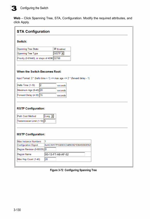
Configuring the Switch3
Web – Click Spanning Tree, STA, Configuration. Modify the required attributes, and click Apply.Figure 3-72 Configuring Spanning Tree
00-13-F7-A8-AF-52
3-130
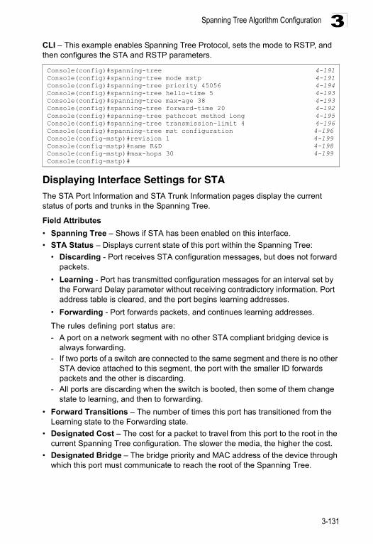
Spanning Tree Algorithm Configuration 3
CLI – This example enables Spanning Tree Protocol, sets the mode to RSTP, and then configures the STA and RSTP parameters.Displaying Interface Settings for STAThe STA Port Information and STA Trunk Information pages display the current status of ports and trunks in the Spanning Tree.
Field Attributes
• Spanning Tree – Shows if STA has been enabled on this interface.
• STA Status – Displays current state of this port within the Spanning Tree:
• Discarding - Port receives STA configuration messages, but does not forward packets.
• Learning - Port has transmitted configuration messages for an interval set by the Forward Delay parameter without receiving contradictory information. Port address table is cleared, and the port begins learning addresses.
• Forwarding - Port forwards packets, and continues learning addresses.
The rules defining port status are:
- A port on a network segment with no other STA compliant bridging device is always forwarding.
- If two ports of a switch are connected to the same segment and there is no other STA device attached to this segment, the port with the smaller ID forwards packets and the other is discarding.
- All ports are discarding when the switch is booted, then some of them change state to learning, and then to forwarding.
• Forward Transitions – The number of times this port has transitioned from the Learning state to the Forwarding state.
• Designated Cost – The cost for a packet to travel from this port to the root in the current Spanning Tree configuration. The slower the media, the higher the cost.
• Designated Bridge – The bridge priority and MAC address of the device through which this port must communicate to reach the root of the Spanning Tree.
Console(config)#spanning-tree 4-191Console(config)#spanning-tree mode mstp 4-191Console(config)#spanning-tree priority 45056 4-194Console(config)#spanning-tree hello-time 5 4-193Console(config)#spanning-tree max-age 38 4-193Console(config)#spanning-tree forward-time 20 4-192Console(config)#spanning-tree pathcost method long 4-195Console(config)#spanning-tree transmission-limit 4 4-196Console(config)#spanning-tree mst configuration 4-196Console(config-mstp)#revision 1 4-199Console(config-mstp)#name R&D 4-198Console(config-mstp)#max-hops 30 4-199Console(config-mstp)#
3-131
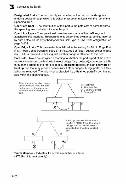
Configuring the Switch3
• Designated Port – The port priority and number of the port on the designatedbridging device through which this switch must communicate with the root of the Spanning Tree.
• Oper Path Cost – The contribution of this port to the path cost of paths towards the spanning tree root which include this port.
• Oper Link Type – The operational point-to-point status of the LAN segment attached to this interface. This parameter is determined by manual configuration or by auto-detection, as described for Admin Link Type in STA Port Configuration on page 3-134.
• Oper Edge Port – This parameter is initialized to the setting for Admin Edge Port in STA Port Configuration on page 3-134 (i.e., true or false), but will be set to false if a BPDU is received, indicating that another bridge is attached to this port.
• Port Role – Roles are assigned according to whether the port is part of the active topology connecting the bridge to the root bridge (i.e., root port), connecting a LAN through the bridge to the root bridge (i.e., designated port), or is an alternate or backup port that may provide connectivity if other bridges, bridge ports, or LANs fail or are removed. The role is set to disabled (i.e., disabled port) if a port has no role within the spanning tree.
• Trunk Member – Indicates if a port is a member of a trunk. (STA Port Information only)
3-132
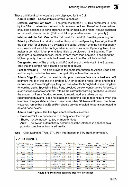
Spanning Tree Algorithm Configuration 3
These additional parameters are only displayed for the CLI:• Admin Status – Shows if this interface is enabled.• External Admin Path Cost – The path cost for the IST. This parameter is used by the STA to determine the best path between devices. Therefore, lower values should be assigned to ports attached to faster media, and higher values assigned to ports with slower media. (Path cost takes precedence over port priority.)
• Internal Admin Path Cost – The path cost for the MST. See the preceding item.
• Priority – Defines the priority used for this port in the Spanning Tree Algorithm. If the path cost for all ports on a switch is the same, the port with the highest priority (i.e., lowest value) will be configured as an active link in the Spanning Tree. This makes a port with higher priority less likely to be blocked if the Spanning Tree Algorithm is detecting network loops. Where more than one port is assigned the highest priority, the port with the lowest numeric identifier will be enabled.
• Designated root – The priority and MAC address of the device in the Spanning Tree that this switch has accepted as the root device.
• Fast forwarding – This field provides the same information as Admin Edge port, and is only included for backward compatibility with earlier products.
• Admin Edge Port – You can enable this option if an interface is attached to a LAN segment that is at the end of a bridged LAN or to an end node. Since end nodes cannot cause forwarding loops, they can pass directly through to the spanning tree forwarding state. Specifying Edge Ports provides quicker convergence for devices such as workstations or servers, retains the current forwarding database to reduce the amount of frame flooding required to rebuild address tables during reconfiguration events, does not cause the spanning tree to reconfigure when the interface changes state, and also overcomes other STA-related timeout problems. However, remember that Edge Port should only be enabled for ports connected to an end-node device.
• Admin Link Type – The link type attached to this interface.
- Point-to-Point – A connection to exactly one other bridge.- Shared – A connection to two or more bridges.- Auto – The switch automatically determines if the interface is attached to a
point-to-point link or to shared media.
Web – Click Spanning Tree, STA, Port Information or STA Trunk Information.
Figure 3-73 Displaying Spanning Tree Port Information
3-133
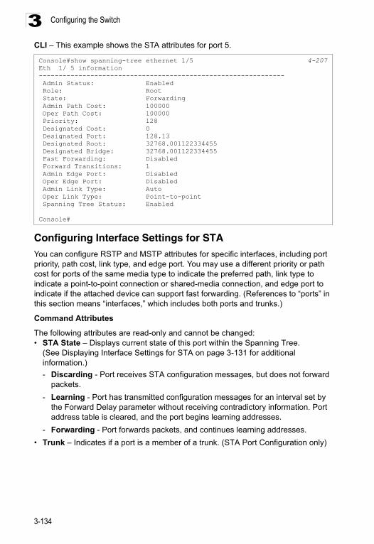
Configuring the Switch3
CLI – This example shows the STA attributes for port 5.Configuring Interface Settings for STAYou can configure RSTP and MSTP attributes for specific interfaces, including port priority, path cost, link type, and edge port. You may use a different priority or path cost for ports of the same media type to indicate the preferred path, link type to indicate a point-to-point connection or shared-media connection, and edge port to indicate if the attached device can support fast forwarding. (References to “ports” in this section means “interfaces,” which includes both ports and trunks.)
Command Attributes
The following attributes are read-only and cannot be changed:• STA State – Displays current state of this port within the Spanning Tree.
(See Displaying Interface Settings for STA on page 3-131 for additional information.)
- Discarding - Port receives STA configuration messages, but does not forward packets.
- Learning - Port has transmitted configuration messages for an interval set by the Forward Delay parameter without receiving contradictory information. Port address table is cleared, and the port begins learning addresses.
- Forwarding - Port forwards packets, and continues learning addresses.
• Trunk – Indicates if a port is a member of a trunk. (STA Port Configuration only)
Console#show spanning-tree ethernet 1/5 4-207Eth 1/ 5 information-------------------------------------------------------------- Admin Status: Enabled Role: Root State: Forwarding Admin Path Cost: 100000 Oper Path Cost: 100000 Priority: 128 Designated Cost: 0 Designated Port: 128.13 Designated Root: 32768.001122334455 Designated Bridge: 32768.001122334455 Fast Forwarding: Disabled Forward Transitions: 1 Admin Edge Port: Disabled Oper Edge Port: Disabled Admin Link Type: Auto Oper Link Type: Point-to-point Spanning Tree Status: Enabled
Console#
3-134
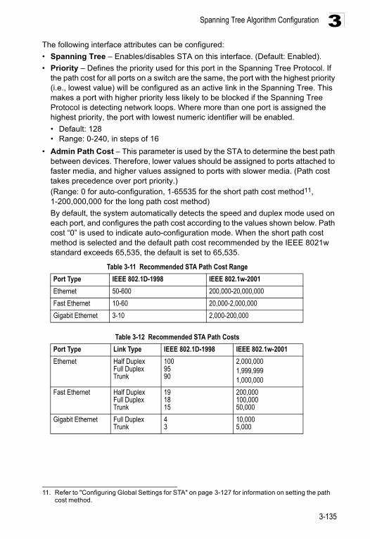
Spanning Tree Algorithm Configuration 3
The following interface attributes can be configured:• Spanning Tree – Enables/disables STA on this interface. (Default: Enabled).
• Priority – Defines the priority used for this port in the Spanning Tree Protocol. If the path cost for all ports on a switch are the same, the port with the highest priority (i.e., lowest value) will be configured as an active link in the Spanning Tree. This makes a port with higher priority less likely to be blocked if the Spanning Tree Protocol is detecting network loops. Where more than one port is assigned the highest priority, the port with lowest numeric identifier will be enabled.
• Default: 128• Range: 0-240, in steps of 16
• Admin Path Cost – This parameter is used by the STA to determine the best path between devices. Therefore, lower values should be assigned to ports attached to faster media, and higher values assigned to ports with slower media. (Path cost takes precedence over port priority.) (Range: 0 for auto-configuration, 1-65535 for the short path cost method11, 1-200,000,000 for the long path cost method)
By default, the system automatically detects the speed and duplex mode used on each port, and configures the path cost according to the values shown below. Path cost “0” is used to indicate auto-configuration mode. When the short path cost method is selected and the default path cost recommended by the IEEE 8021w standard exceeds 65,535, the default is set to 65,535.
11. Refer to "Configuring Global Settings for STA" on page 3-127 for information on setting the path cost method.
Table 3-11 Recommended STA Path Cost Range
Port Type IEEE 802.1D-1998 IEEE 802.1w-2001
Ethernet 50-600 200,000-20,000,000
Fast Ethernet 10-60 20,000-2,000,000
Gigabit Ethernet 3-10 2,000-200,000
Table 3-12 Recommended STA Path Costs
Port Type Link Type IEEE 802.1D-1998 IEEE 802.1w-2001
Ethernet Half DuplexFull DuplexTrunk
1009590
2,000,0001,999,9991,000,000
Fast Ethernet Half DuplexFull DuplexTrunk
191815
200,000100,00050,000
Gigabit Ethernet Full DuplexTrunk
43
10,0005,000
3-135
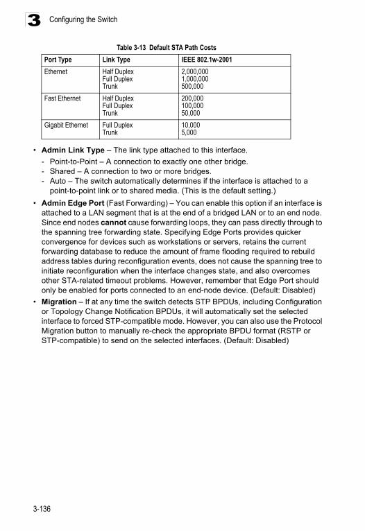
Configuring the Switch3
• Admin Link Type – The link type attached to this interface.
- Point-to-Point – A connection to exactly one other bridge.- Shared – A connection to two or more bridges.- Auto – The switch automatically determines if the interface is attached to a
point-to-point link or to shared media. (This is the default setting.)
• Admin Edge Port (Fast Forwarding) – You can enable this option if an interface is attached to a LAN segment that is at the end of a bridged LAN or to an end node. Since end nodes cannot cause forwarding loops, they can pass directly through to the spanning tree forwarding state. Specifying Edge Ports provides quicker convergence for devices such as workstations or servers, retains the current forwarding database to reduce the amount of frame flooding required to rebuild address tables during reconfiguration events, does not cause the spanning tree to initiate reconfiguration when the interface changes state, and also overcomes other STA-related timeout problems. However, remember that Edge Port should only be enabled for ports connected to an end-node device. (Default: Disabled)
• Migration – If at any time the switch detects STP BPDUs, including Configuration or Topology Change Notification BPDUs, it will automatically set the selected interface to forced STP-compatible mode. However, you can also use the Protocol Migration button to manually re-check the appropriate BPDU format (RSTP or STP-compatible) to send on the selected interfaces. (Default: Disabled)
Table 3-13 Default STA Path Costs
Port Type Link Type IEEE 802.1w-2001
Ethernet Half DuplexFull DuplexTrunk
2,000,0001,000,000500,000
Fast Ethernet Half DuplexFull DuplexTrunk
200,000100,00050,000
Gigabit Ethernet Full DuplexTrunk
10,0005,000
3-136
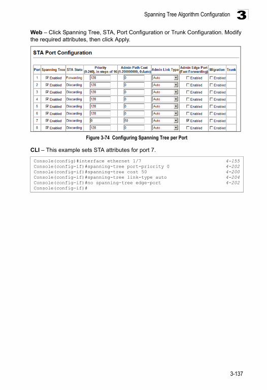
Spanning Tree Algorithm Configuration 3
Web – Click Spanning Tree, STA, Port Configuration or Trunk Configuration. Modify the required attributes, then click Apply.Figure 3-74 Configuring Spanning Tree per Port
CLI – This example sets STA attributes for port 7.
Console(config)#interface ethernet 1/7 4-155Console(config-if)#spanning-tree port-priority 0 4-202Console(config-if)#spanning-tree cost 50 4-200Console(config-if)#spanning-tree link-type auto 4-204Console(config-if)#no spanning-tree edge-port 4-202Console(config-if)#
3-137
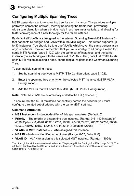
Configuring the Switch3
Configuring Multiple Spanning TreesMSTP generates a unique spanning tree for each instance. This provides multiple pathways across the network, thereby balancing the traffic load, preventing wide-scale disruption when a bridge node in a single instance fails, and allowing for faster convergence of a new topology for the failed instance.By default all VLANs are assigned to the Internal Spanning Tree (MST Instance 0) that connects all bridges and LANs within the MST region. This switch supports up to 33 instances. You should try to group VLANs which cover the same general area of your network. However, remember that you must configure all bridges within the same MSTI Region (page 3-129) with the same set of instances, and the same instance (on each bridge) with the same set of VLANs. Also, note that RSTP treats each MSTI region as a single node, connecting all regions to the Common Spanning Tree.
To use multiple spanning trees:
1. Set the spanning tree type to MSTP (STA Configuration, page 3-122).
2. Enter the spanning tree priority for the selected MST instance (MSTP VLAN Configuration).
3. Add the VLANs that will share this MSTI (MSTP VLAN Configuration).
Note: Note: All VLANs are automatically added to the IST (Instance 0).
To ensure that the MSTI maintains connectivity across the network, you must configure a related set of bridges with the same MSTI settings.
Command Attributes
• MST Instance – Instance identifier of this spanning tree. (Default: 0)
• Priority – The priority of a spanning tree instance. (Range: 0-61440 in steps of 4096; Options: 0, 4096, 8192, 12288, 16384, 20480, 24576, 28672, 32768, 36864, 40960, 45056, 49152, 53248, 57344, 61440; Default: 32768)
• VLANs in MST Instance – VLANs assigned this instance.
• MST ID – Instance identifier to configure. (Range: 0-57; Default: 0)
• VLAN ID – VLAN to assign to this selected MST instance. (Range: 1-4094)
The other global attributes are described under “Displaying Global Settings for STA,” page 3-124. The attributes displayed by the CLI for individual interfaces are described under “Displaying Interface Settings for STA,” page 3-131
3-138
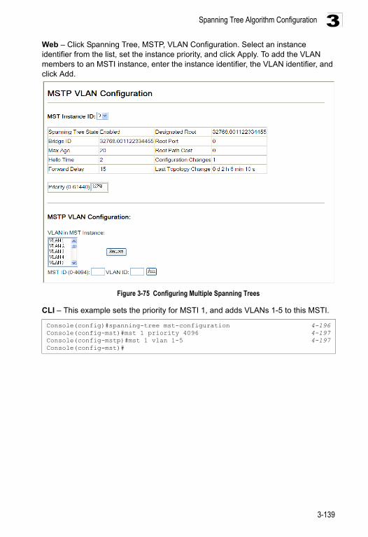
Spanning Tree Algorithm Configuration 3
Web – Click Spanning Tree, MSTP, VLAN Configuration. Select an instance identifier from the list, set the instance priority, and click Apply. To add the VLAN members to an MSTI instance, enter the instance identifier, the VLAN identifier, and click Add.Figure 3-75 Configuring Multiple Spanning Trees
CLI – This example sets the priority for MSTI 1, and adds VLANs 1-5 to this MSTI.
Console(config)#spanning-tree mst-configuration 4-196Console(config-mst)#mst 1 priority 4096 4-197Console(config-mstp)#mst 1 vlan 1-5 4-197Console(config-mst)#
3-139
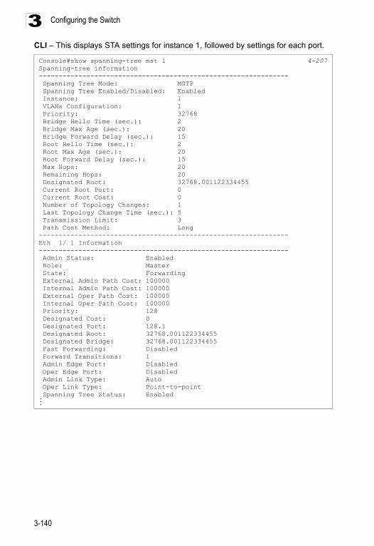
Configuring the Switch3
CLI – This displays STA settings for instance 1, followed by settings for each port.Console#show spanning-tree mst 1 4-207Spanning-tree information--------------------------------------------------------------- Spanning Tree Mode: MSTP Spanning Tree Enabled/Disabled: Enabled Instance: 1 VLANs Configuration: 1 Priority: 32768 Bridge Hello Time (sec.): 2 Bridge Max Age (sec.): 20 Bridge Forward Delay (sec.): 15 Root Hello Time (sec.): 2 Root Max Age (sec.): 20 Root Forward Delay (sec.): 15 Max Hops: 20 Remaining Hops: 20 Designated Root: 32768.001122334455 Current Root Port: 0 Current Root Cost: 0 Number of Topology Changes: 1 Last Topology Change Time (sec.): 5 Transmission Limit: 3 Path Cost Method: Long---------------------------------------------------------------Eth 1/ 1 Information--------------------------------------------------------------- Admin Status: Enabled Role: Master State: Forwarding External Admin Path Cost: 100000 Internal Admin Path Cost: 100000 External Oper Path Cost: 100000 Internal Oper Path Cost: 100000 Priority: 128 Designated Cost: 0 Designated Port: 128.1 Designated Root: 32768.001122334455 Designated Bridge: 32768.001122334455 Fast Forwarding: Disabled Forward Transitions: 1 Admin Edge Port: Disabled Oper Edge Port: Disabled Admin Link Type: Auto Oper Link Type: Point-to-point Spanning Tree Status: Enabled...
3-140
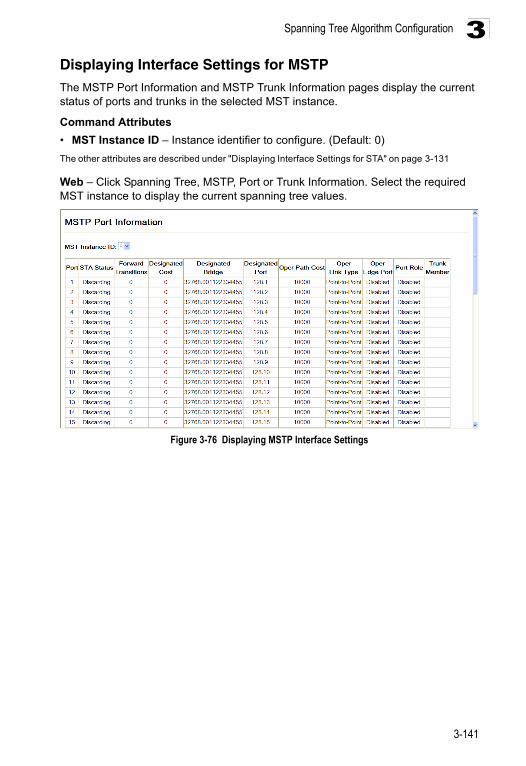
Spanning Tree Algorithm Configuration 3
Displaying Interface Settings for MSTPThe MSTP Port Information and MSTP Trunk Information pages display the current status of ports and trunks in the selected MST instance.Command Attributes
• MST Instance ID – Instance identifier to configure. (Default: 0)
The other attributes are described under "Displaying Interface Settings for STA" on page 3-131
Web – Click Spanning Tree, MSTP, Port or Trunk Information. Select the required MST instance to display the current spanning tree values.
Figure 3-76 Displaying MSTP Interface Settings
3-141
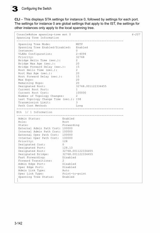
Configuring the Switch3
CLI – This displays STA settings for instance 0, followed by settings for each port. The settings for instance 0 are global settings that apply to the IST, the settings for other instances only apply to the local spanning tree.Console#show spanning-tree mst 0 4-207Spanning Tree Information--------------------------------------------------------------- Spanning Tree Mode: MSTP Spanning Tree Enabled/Disabled: Enabled Instance: 0 VLANs Configuration: 2-4094 Priority: 32768 Bridge Hello Time (sec.): 2 Bridge Max Age (sec.): 20 Bridge Forward Delay (sec.): 15 Root Hello Time (sec.): 2 Root Max Age (sec.): 20 Root Forward Delay (sec.): 15 Max Hops: 20 Remaining Hops: 20 Designated Root: 32768.001122334455 Current Root Port: 1 Current Root Cost: 100000 Number of Topology Changes: 2 Last Topology Change Time (sec.): 158 Transmission Limit: 3 Path Cost Method: Long---------------------------------------------------------------Eth 1/ 1 Information--------------------------------------------------------------- Admin Status: Enabled Role: Root State: Forwarding External Admin Path Cost: 100000 Internal Admin Path Cost: 100000 External Oper Path Cost: 100000 Internal Oper Path Cost: 100000 Priority: 128 Designated Cost: 0 Designated Port: 128.13 Designated Root: 32768.001122334455 Designated Bridge: 32768.001122334455 Fast Forwarding: Disabled Forward Transitions: 2 Admin Edge Port: Disabled Oper Edge Port: Disabled Admin Link Type: Auto Oper Link Type: Point-to-point Spanning Tree Status: Enabled...
3-142
Spanning Tree Algorithm Configuration 3
Configuring Interface Settings for MSTPYou can configure the STA interface settings for an MST Instance using the MSTP Port Configuration and MSTP Trunk Configuration pages.Field Attributes
The following attributes are read-only and cannot be changed:
• STA State – Displays current state of this port within the Spanning Tree. (See "Displaying Interface Settings for STA" on page 3-131 for additional information.)
- Discarding – Port receives STA configuration messages, but does not forward packets.
- Learning – Port has transmitted configuration messages for an interval set by the Forward Delay parameter without receiving contradictory information. Port address table is cleared, and the port begins learning addresses.
- Forwarding – Port forwards packets, and continues learning addresses.• Trunk – Indicates if a port is a member of a trunk. (STA Port Configuration only)
The following interface attributes can be configured:
• MST Instance ID – Instance identifier to configure. (Default: 0)
• Priority – Defines the priority used for this port in the Spanning Tree Protocol. If the path cost for all ports on a switch are the same, the port with the highest priority (i.e., lowest value) will be configured as an active link in the Spanning Tree. This makes a port with higher priority less likely to be blocked if the Spanning Tree Protocol is detecting network loops. Where more than one port is assigned the highest priority, the port with lowest numeric identifier will be enabled. (Default: 128; Range: 0-240, in steps of 16)
• Admin MST Path Cost – This parameter is used by the MSTP to determine the best path between devices. Therefore, lower values should be assigned to ports attached to faster media, and higher values assigned to ports with slower media. (Path cost takes precedence over port priority.) Note that when the Path Cost Method is set to short (page 3-63), the maximum path cost is 65,535.
By default, the system automatically detects the speed and duplex mode used on each port, and configures the path cost according to the values shown below. Path cost “0” is used to indicate auto-configuration mode. When the short path cost method is selected and the default path cost recommended by the IEEE 8021w standard exceeds 65,535, the default is set to 65,535
The recommended range is listed in Table 3-11 on page 3-135. The recommended path cost is listed in Table 3-12 on page 3-135.
The default path costs are listed in Table 3-13 on page 3-136.
3-143
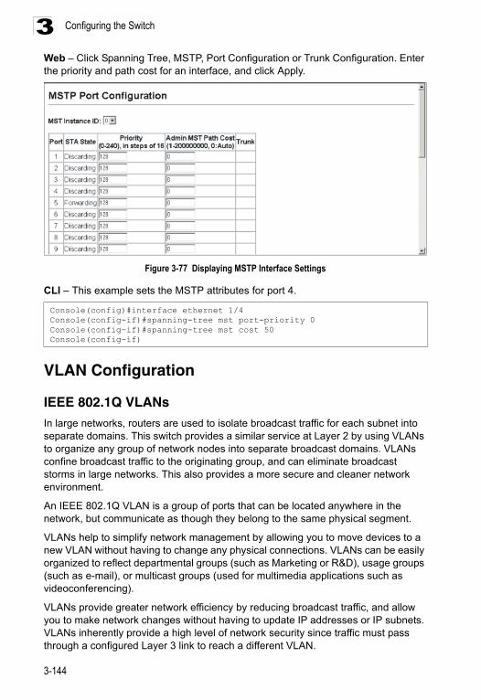
Configuring the Switch3
Web – Click Spanning Tree, MSTP, Port Configuration or Trunk Configuration. Enter the priority and path cost for an interface, and click Apply.Figure 3-77 Displaying MSTP Interface Settings
CLI – This example sets the MSTP attributes for port 4.
VLAN Configuration
IEEE 802.1Q VLANs
In large networks, routers are used to isolate broadcast traffic for each subnet into separate domains. This switch provides a similar service at Layer 2 by using VLANs to organize any group of network nodes into separate broadcast domains. VLANs confine broadcast traffic to the originating group, and can eliminate broadcast storms in large networks. This also provides a more secure and cleaner network environment.
An IEEE 802.1Q VLAN is a group of ports that can be located anywhere in the network, but communicate as though they belong to the same physical segment.
VLANs help to simplify network management by allowing you to move devices to a new VLAN without having to change any physical connections. VLANs can be easily organized to reflect departmental groups (such as Marketing or R&D), usage groups (such as e-mail), or multicast groups (used for multimedia applications such as videoconferencing).
VLANs provide greater network efficiency by reducing broadcast traffic, and allow you to make network changes without having to update IP addresses or IP subnets. VLANs inherently provide a high level of network security since traffic must pass through a configured Layer 3 link to reach a different VLAN.
Console(config)#interface ethernet 1/4 Console(config-if)#spanning-tree mst port-priority 0 Console(config-if)#spanning-tree mst cost 50Console(config-if)
3-144
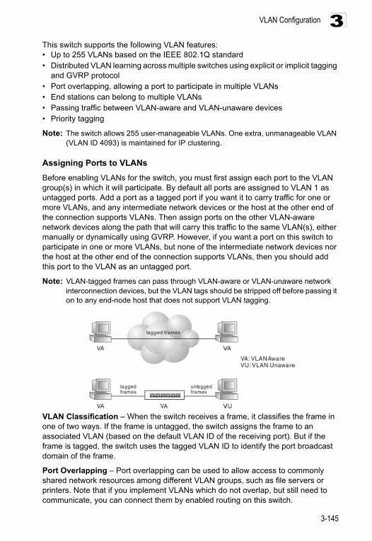
VLAN Configuration 3
This switch supports the following VLAN features:• Up to 255 VLANs based on the IEEE 802.1Q standard• Distributed VLAN learning across multiple switches using explicit or implicit taggingand GVRP protocol• Port overlapping, allowing a port to participate in multiple VLANs• End stations can belong to multiple VLANs• Passing traffic between VLAN-aware and VLAN-unaware devices • Priority tagging
Note: The switch allows 255 user-manageable VLANs. One extra, unmanageable VLAN (VLAN ID 4093) is maintained for IP clustering.
Assigning Ports to VLANs
Before enabling VLANs for the switch, you must first assign each port to the VLAN group(s) in which it will participate. By default all ports are assigned to VLAN 1 as untagged ports. Add a port as a tagged port if you want it to carry traffic for one or more VLANs, and any intermediate network devices or the host at the other end of the connection supports VLANs. Then assign ports on the other VLAN-aware network devices along the path that will carry this traffic to the same VLAN(s), either manually or dynamically using GVRP. However, if you want a port on this switch to participate in one or more VLANs, but none of the intermediate network devices nor the host at the other end of the connection supports VLANs, then you should add this port to the VLAN as an untagged port.
Note: VLAN-tagged frames can pass through VLAN-aware or VLAN-unaware network interconnection devices, but the VLAN tags should be stripped off before passing it on to any end-node host that does not support VLAN tagging.
VLAN Classification – When the switch receives a frame, it classifies the frame in one of two ways. If the frame is untagged, the switch assigns the frame to an associated VLAN (based on the default VLAN ID of the receiving port). But if the frame is tagged, the switch uses the tagged VLAN ID to identify the port broadcast domain of the frame.
Port Overlapping – Port overlapping can be used to allow access to commonly shared network resources among different VLAN groups, such as file servers or printers. Note that if you implement VLANs which do not overlap, but still need to communicate, you can connect them by enabled routing on this switch.
3-145
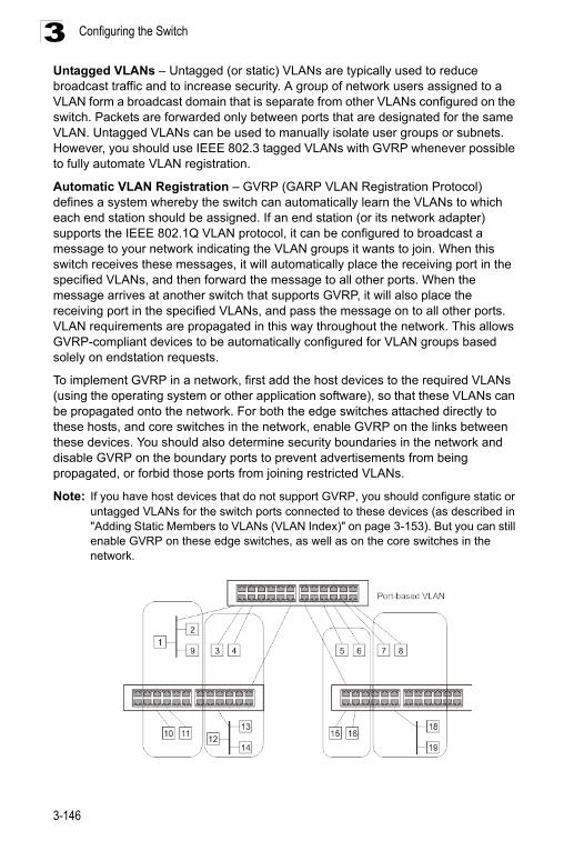
Configuring the Switch3
Untagged VLANs – Untagged (or static) VLANs are typically used to reduce broadcast traffic and to increase security. A group of network users assigned to a VLAN form a broadcast domain that is separate from other VLANs configured on the switch. Packets are forwarded only between ports that are designated for the same VLAN. Untagged VLANs can be used to manually isolate user groups or subnets. However, you should use IEEE 802.3 tagged VLANs with GVRP whenever possible to fully automate VLAN registration.Automatic VLAN Registration – GVRP (GARP VLAN Registration Protocol) defines a system whereby the switch can automatically learn the VLANs to which each end station should be assigned. If an end station (or its network adapter) supports the IEEE 802.1Q VLAN protocol, it can be configured to broadcast a message to your network indicating the VLAN groups it wants to join. When this switch receives these messages, it will automatically place the receiving port in the specified VLANs, and then forward the message to all other ports. When the message arrives at another switch that supports GVRP, it will also place the receiving port in the specified VLANs, and pass the message on to all other ports. VLAN requirements are propagated in this way throughout the network. This allows GVRP-compliant devices to be automatically configured for VLAN groups based solely on endstation requests.
To implement GVRP in a network, first add the host devices to the required VLANs (using the operating system or other application software), so that these VLANs can be propagated onto the network. For both the edge switches attached directly to these hosts, and core switches in the network, enable GVRP on the links between these devices. You should also determine security boundaries in the network and disable GVRP on the boundary ports to prevent advertisements from being propagated, or forbid those ports from joining restricted VLANs.
Note: If you have host devices that do not support GVRP, you should configure static or untagged VLANs for the switch ports connected to these devices (as described in "Adding Static Members to VLANs (VLAN Index)" on page 3-153). But you can still enable GVRP on these edge switches, as well as on the core switches in the network.
3-146
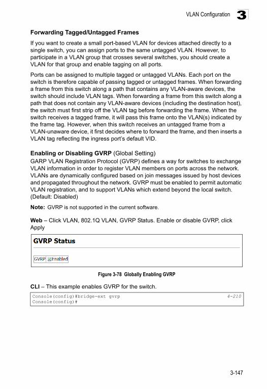
VLAN Configuration 3
Forwarding Tagged/Untagged FramesIf you want to create a small port-based VLAN for devices attached directly to a single switch, you can assign ports to the same untagged VLAN. However, to participate in a VLAN group that crosses several switches, you should create a VLAN for that group and enable tagging on all ports.
Ports can be assigned to multiple tagged or untagged VLANs. Each port on the switch is therefore capable of passing tagged or untagged frames. When forwarding a frame from this switch along a path that contains any VLAN-aware devices, the switch should include VLAN tags. When forwarding a frame from this switch along a path that does not contain any VLAN-aware devices (including the destination host), the switch must first strip off the VLAN tag before forwarding the frame. When the switch receives a tagged frame, it will pass this frame onto the VLAN(s) indicated by the frame tag. However, when this switch receives an untagged frame from a VLAN-unaware device, it first decides where to forward the frame, and then inserts a VLAN tag reflecting the ingress port’s default VID.
Enabling or Disabling GVRP (Global Setting) GARP VLAN Registration Protocol (GVRP) defines a way for switches to exchange VLAN information in order to register VLAN members on ports across the network. VLANs are dynamically configured based on join messages issued by host devices and propagated throughout the network. GVRP must be enabled to permit automatic VLAN registration, and to support VLANs which extend beyond the local switch. (Default: Disabled)
Note: GVRP is not supported in the current software.
Web – Click VLAN, 802.1Q VLAN, GVRP Status. Enable or disable GVRP, click Apply
Figure 3-78 Globally Enabling GVRP
CLI – This example enables GVRP for the switch.
Console(config)#bridge-ext gvrp 4-210Console(config)#
3-147
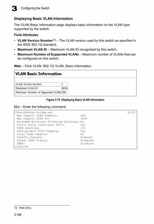
Configuring the Switch3
Displaying Basic VLAN InformationThe VLAN Basic Information page displays basic information on the VLAN type supported by the switch.
Field Attributes
• VLAN Version Number12 – The VLAN version used by this switch as specified in the IEEE 802.1Q standard.
• Maximum VLAN ID – Maximum VLAN ID recognized by this switch.
• Maximum Number of Supported VLANs – Maximum number of VLANs that can be configured on this switch.
Web – Click VLAN, 802.1Q VLAN, Basic Information.
Figure 3-79 Displaying Basic VLAN Information
CLI – Enter the following command.
12. Web Only.
Console#show bridge-ext 4-211 Max Support VLAN Numbers: 256 Max Support VLAN ID: 4094 Extended Multicast Filtering Services: No Static Entry Individual Port: Yes VLAN Learning: IVL Configurable PVID Tagging: Yes Local VLAN Capable: No Traffic Classes: Enabled Global GVRP Status: Disabled GMRP: DisabledConsole#
3-148
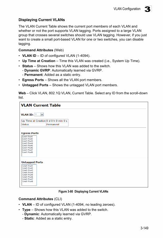
VLAN Configuration 3
Displaying Current VLANsThe VLAN Current Table shows the current port members of each VLAN and whether or not the port supports VLAN tagging. Ports assigned to a large VLAN group that crosses several switches should use VLAN tagging. However, if you just want to create a small port-based VLAN for one or two switches, you can disable tagging.
Command Attributes (Web)
• VLAN ID – ID of configured VLAN (1-4094).
• Up Time at Creation – Time this VLAN was created (i.e., System Up Time).
• Status – Shows how this VLAN was added to the switch. - Dynamic GVRP: Automatically learned via GVRP.- Permanent: Added as a static entry.
• Egress Ports – Shows all the VLAN port members.
• Untagged Ports – Shows the untagged VLAN port members.
Web – Click VLAN, 802.1Q VLAN, Current Table. Select any ID from the scroll-down list.
Figure 3-80 Displaying Current VLANs
Command Attributes (CLI)
• VLAN – ID of configured VLAN (1-4094, no leading zeroes).
• Type – Shows how this VLAN was added to the switch.- Dynamic: Automatically learned via GVRP.- Static: Added as a static entry.
3-149
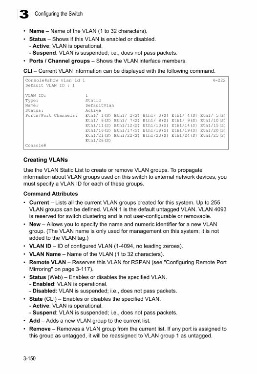
Configuring the Switch3
• Name – Name of the VLAN (1 to 32 characters).• Status – Shows if this VLAN is enabled or disabled. - Active: VLAN is operational.- Suspend: VLAN is suspended; i.e., does not pass packets.
• Ports / Channel groups – Shows the VLAN interface members.
CLI – Current VLAN information can be displayed with the following command.
Creating VLANs
Use the VLAN Static List to create or remove VLAN groups. To propagate information about VLAN groups used on this switch to external network devices, you must specify a VLAN ID for each of these groups.
Command Attributes
• Current – Lists all the current VLAN groups created for this system. Up to 255 VLAN groups can be defined. VLAN 1 is the default untagged VLAN. VLAN 4093 is reserved for switch clustering and is not user-configurable or removable.
• New – Allows you to specify the name and numeric identifier for a new VLAN group. (The VLAN name is only used for management on this system; it is not added to the VLAN tag.)
• VLAN ID – ID of configured VLAN (1-4094, no leading zeroes).
• VLAN Name – Name of the VLAN (1 to 32 characters).
• Remote VLAN – Reserves this VLAN for RSPAN (see "Configuring Remote Port Mirroring" on page 3-117).
• Status (Web) – Enables or disables the specified VLAN. - Enabled: VLAN is operational.- Disabled: VLAN is suspended; i.e., does not pass packets.
• State (CLI) – Enables or disables the specified VLAN. - Active: VLAN is operational.- Suspend: VLAN is suspended; i.e., does not pass packets.
• Add – Adds a new VLAN group to the current list.
• Remove – Removes a VLAN group from the current list. If any port is assigned to this group as untagged, it will be reassigned to VLAN group 1 as untagged.
Console#show vlan id 1 4-222Default VLAN ID : 1
VLAN ID: 1Type: StaticName: DefaultVlanStatus: ActivePorts/Port Channels: Eth1/ 1(S) Eth1/ 2(S) Eth1/ 3(S) Eth1/ 4(S) Eth1/ 5(S) Eth1/ 6(S) Eth1/ 7(S) Eth1/ 8(S) Eth1/ 9(S) Eth1/10(S) Eth1/11(S) Eth1/12(S) Eth1/13(S) Eth1/14(S) Eth1/15(S) Eth1/16(S) Eth1/17(S) Eth1/18(S) Eth1/19(S) Eth1/20(S) Eth1/21(S) Eth1/22(S) Eth1/23(S) Eth1/24(S) Eth1/25(S) Eth1/26(S)Console#
3-150
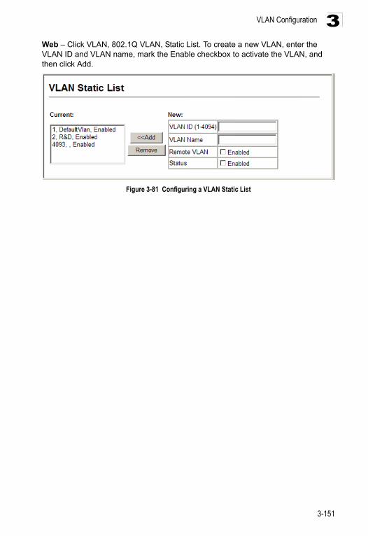
VLAN Configuration 3
Web – Click VLAN, 802.1Q VLAN, Static List. To create a new VLAN, enter the VLAN ID and VLAN name, mark the Enable checkbox to activate the VLAN, and then click Add.Figure 3-81 Configuring a VLAN Static List
3-151
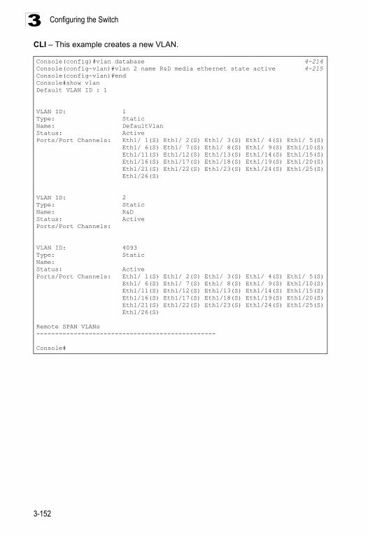
Configuring the Switch3
CLI – This example creates a new VLAN.Console(config)#vlan database 4-214Console(config-vlan)#vlan 2 name R&D media ethernet state active 4-215Console(config-vlan)#endConsole#show vlanDefault VLAN ID : 1
VLAN ID: 1Type: StaticName: DefaultVlanStatus: ActivePorts/Port Channels: Eth1/ 1(S) Eth1/ 2(S) Eth1/ 3(S) Eth1/ 4(S) Eth1/ 5(S) Eth1/ 6(S) Eth1/ 7(S) Eth1/ 8(S) Eth1/ 9(S) Eth1/10(S) Eth1/11(S) Eth1/12(S) Eth1/13(S) Eth1/14(S) Eth1/15(S) Eth1/16(S) Eth1/17(S) Eth1/18(S) Eth1/19(S) Eth1/20(S) Eth1/21(S) Eth1/22(S) Eth1/23(S) Eth1/24(S) Eth1/25(S) Eth1/26(S)
VLAN ID: 2Type: StaticName: R&DStatus: ActivePorts/Port Channels:
VLAN ID: 4093Type: StaticName:Status: ActivePorts/Port Channels: Eth1/ 1(S) Eth1/ 2(S) Eth1/ 3(S) Eth1/ 4(S) Eth1/ 5(S) Eth1/ 6(S) Eth1/ 7(S) Eth1/ 8(S) Eth1/ 9(S) Eth1/10(S) Eth1/11(S) Eth1/12(S) Eth1/13(S) Eth1/14(S) Eth1/15(S) Eth1/16(S) Eth1/17(S) Eth1/18(S) Eth1/19(S) Eth1/20(S) Eth1/21(S) Eth1/22(S) Eth1/23(S) Eth1/24(S) Eth1/25(S) Eth1/26(S)
Remote SPAN VLANs------------------------------------------------
Console#
3-152
VLAN Configuration 3
Adding Static Members to VLANs (VLAN Index)Use the VLAN Static Table to configure port members for the selected VLAN index. Assign ports as tagged if they are connected to 802.1Q VLAN compliant devices, or untagged they are not connected to any VLAN-aware devices. Or configure a port as forbidden to prevent the switch from automatically adding it to a VLAN via the GVRP protocol.
Notes: 1. You can also use the VLAN Static Membership by Port page to configure VLAN groups based on the port index (page 3-155). However, note that this configuration page can only add ports to a VLAN as tagged members.
2. VLAN 1 is the default untagged VLAN containing all ports on the switch, and can only be modified by first reassigning the default port VLAN ID as described under "Configuring VLAN Behavior for Interfaces" on page 3-156.
Command Attributes
• VLAN – ID of configured VLAN (1-4094).
• Name – Name of the VLAN (1 to 32 characters).
• Status – Enables or disables the specified VLAN.
- Enable: VLAN is operational.- Disable: VLAN is suspended; i.e., does not pass packets.
• Port – Port identifier.
• Membership Type – Select VLAN membership for each interface by marking the appropriate radio button for a port or trunk:
- Tagged: Interface is a member of the VLAN. All packets transmitted by the port will be tagged, that is, carry a tag and therefore carry VLAN or CoS information.
- Untagged: Interface is a member of the VLAN. All packets transmitted by the port will be untagged, that is, not carry a tag and therefore not carry VLAN or CoS information. Note that an interface must be assigned to at least one group as an untagged port.
- Forbidden: Interface is forbidden from automatically joining the VLAN via GVRP. For more information, see “Automatic VLAN Registration” on page 3-146.
- None: Interface is not a member of the VLAN. Packets associated with this VLAN will not be transmitted by the interface.
- Trunk Member – Indicates if a port is a member of a trunk. To add a trunk to the selected VLAN, use the last table on the VLAN Static Table page.
3-153
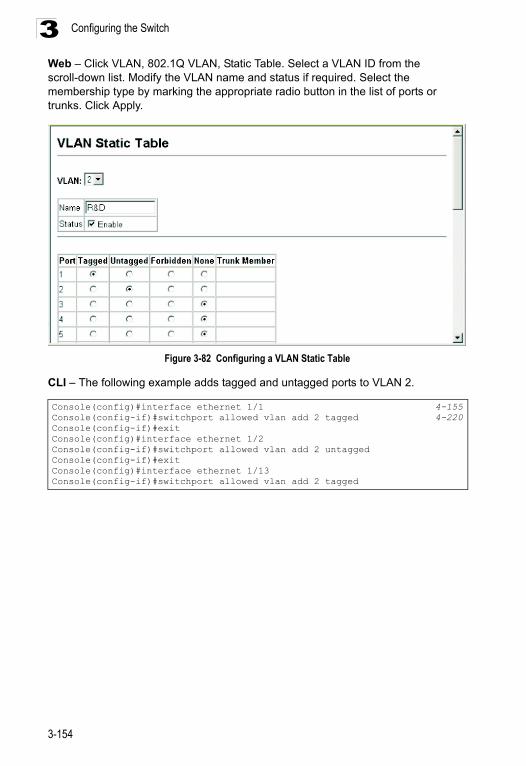
Configuring the Switch3
Web – Click VLAN, 802.1Q VLAN, Static Table. Select a VLAN ID from the scroll-down list. Modify the VLAN name and status if required. Select the membership type by marking the appropriate radio button in the list of ports or trunks. Click Apply.Figure 3-82 Configuring a VLAN Static Table
CLI – The following example adds tagged and untagged ports to VLAN 2.
Console(config)#interface ethernet 1/1 4-155Console(config-if)#switchport allowed vlan add 2 tagged 4-220Console(config-if)#exitConsole(config)#interface ethernet 1/2Console(config-if)#switchport allowed vlan add 2 untaggedConsole(config-if)#exitConsole(config)#interface ethernet 1/13Console(config-if)#switchport allowed vlan add 2 tagged
3-154
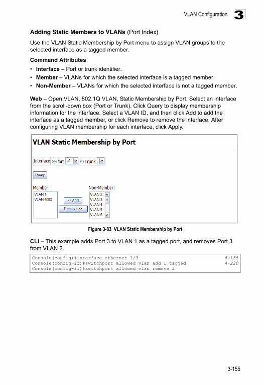
VLAN Configuration 3
Adding Static Members to VLANs (Port Index)Use the VLAN Static Membership by Port menu to assign VLAN groups to the selected interface as a tagged member.
Command Attributes
• Interface – Port or trunk identifier.
• Member – VLANs for which the selected interface is a tagged member.
• Non-Member – VLANs for which the selected interface is not a tagged member.
Web – Open VLAN, 802.1Q VLAN, Static Membership by Port. Select an interface from the scroll-down box (Port or Trunk). Click Query to display membership information for the interface. Select a VLAN ID, and then click Add to add the interface as a tagged member, or click Remove to remove the interface. After configuring VLAN membership for each interface, click Apply.
Figure 3-83 VLAN Static Membership by Port
CLI – This example adds Port 3 to VLAN 1 as a tagged port, and removes Port 3 from VLAN 2.
Console(config)#interface ethernet 1/3 4-155Console(config-if)#switchport allowed vlan add 1 tagged 4-220Console(config-if)#switchport allowed vlan remove 2
3-155
Configuring the Switch3
Configuring VLAN Behavior for InterfacesYou can configure VLAN behavior for specific interfaces, including the default VLAN identifier (PVID), accepted frame types, ingress filtering, GVRP status, and GARP timers.
Command Usage
• GVRP – GARP VLAN Registration Protocol defines a way for switches to exchange VLAN information in order to automatically register VLAN members on interfaces across the network.
• GARP – Group Address Registration Protocol is used by GVRP to register or deregister client attributes for client services within a bridged LAN. The default values for the GARP timers are independent of the media access method or data rate. These values should not be changed unless you are experiencing difficulties with GVRP registration/deregistration.
Command Attributes
• PVID – VLAN ID assigned to untagged frames received on the interface. (Default: 1)
- If an interface is not a member of VLAN 1 and you assign its PVID to this VLAN, the interface will automatically be added to VLAN 1 as an untagged member. For all other VLANs, the PVID must be defined first, then the status of the VLAN can be configured as a tagged or untagged member.
• Acceptable Frame Type – Sets the interface to accept all frame types, including tagged or untagged frames, or only tagged frames. When set to receive all frame types, any received frames that are untagged are assigned to the default VLAN. (Options: All, Tagged; Default: All)
• Ingress Filtering – Determines how to process frames tagged for VLANs for which the ingress port is not a member. (Default: Disabled)
- Ingress filtering only affects tagged frames. - If ingress filtering is disabled and a port receives frames tagged for VLANs for
which it is not a member, these frames will be flooded to all other ports (except for those VLANs explicitly forbidden on this port).
- If ingress filtering is enabled and a port receives frames tagged for VLANs for which it is not a member, these frames will be discarded.
- Ingress filtering does not affect VLAN independent BPDU frames, such as GVRP or STP. However, they do affect VLAN dependent BPDU frames, such as GMRP.
• GVRP Status – Enables/disables GVRP for the interface. GVRP must be globally enabled for the switch before this setting can take effect. (See "Displaying Bridge Extension Capabilities" on page 3-14.) When disabled, any GVRP packets received on this port will be discarded and no GVRP registrations will be propagated from other ports. (Default: Disabled)
• GARP Join Timer13 – The interval between transmitting requests/queries to participate in a VLAN group. (Range: 20-1000 centiseconds; Default: 20)
13. Timer settings must follow this rule: 2 x (join timer) < leave timer < leaveAll timer
3-156
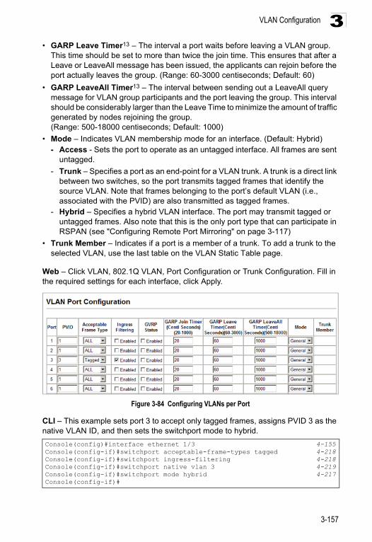
VLAN Configuration 3
• GARP Leave Timer13 – The interval a port waits before leaving a VLAN group.This time should be set to more than twice the join time. This ensures that after a Leave or LeaveAll message has been issued, the applicants can rejoin before the port actually leaves the group. (Range: 60-3000 centiseconds; Default: 60)
• GARP LeaveAll Timer13 – The interval between sending out a LeaveAll query message for VLAN group participants and the port leaving the group. This interval should be considerably larger than the Leave Time to minimize the amount of traffic generated by nodes rejoining the group.(Range: 500-18000 centiseconds; Default: 1000)
• Mode – Indicates VLAN membership mode for an interface. (Default: Hybrid)- Access - Sets the port to operate as an untagged interface. All frames are sent
untagged.
- Trunk – Specifies a port as an end-point for a VLAN trunk. A trunk is a direct link between two switches, so the port transmits tagged frames that identify the source VLAN. Note that frames belonging to the port’s default VLAN (i.e., associated with the PVID) are also transmitted as tagged frames.
- Hybrid – Specifies a hybrid VLAN interface. The port may transmit tagged or untagged frames. Also note that this is the only port type that can participate in RSPAN (see "Configuring Remote Port Mirroring" on page 3-117)
• Trunk Member – Indicates if a port is a member of a trunk. To add a trunk to the selected VLAN, use the last table on the VLAN Static Table page.
Web – Click VLAN, 802.1Q VLAN, Port Configuration or Trunk Configuration. Fill in the required settings for each interface, click Apply.
Figure 3-84 Configuring VLANs per Port
CLI – This example sets port 3 to accept only tagged frames, assigns PVID 3 as the native VLAN ID, and then sets the switchport mode to hybrid.
Console(config)#interface ethernet 1/3 4-155Console(config-if)#switchport acceptable-frame-types tagged 4-218Console(config-if)#switchport ingress-filtering 4-218Console(config-if)#switchport native vlan 3 4-219Console(config-if)#switchport mode hybrid 4-217Console(config-if)#
3-157
Configuring the Switch3
Configuring IEEE 802.1Q TunnelingIEEE 802.1Q Tunneling (QinQ) is designed for service providers carrying traffic for multiple customers across their networks. QinQ tunneling is used to maintain customer-specific VLAN and Layer 2 protocol configurations even when different customers use the same internal VLAN IDs. This is accomplished by inserting Service Provider VLAN (SPVLAN) tags into the customer’s frames when they enter the service provider’s network, and then stripping the tags when the frames leave the network.A service provider’s customers may have specific requirements for their internal VLAN IDs and number of VLANs supported. VLAN ranges required by different customers in the same service-provider network might easily overlap, and traffic passing through the infrastructure might be mixed. Assigning a unique range of VLAN IDs to each customer would restrict customer configurations, require intensive processing of VLAN mapping tables, and could easily exceed the maximum VLAN limit of 4096.
QinQ tunneling uses a single Service Provider VLAN (SPVLAN) for customers who have multiple VLANs. Customer VLAN IDs are preserved and traffic from different customers is segregated within the service provider’s network even when they use the same customer-specific VLAN IDs. QinQ tunneling expands VLAN space by using a VLAN-in-VLAN hierarchy, preserving the customer’s original tagged packets, and adding SPVLAN tags to each frame (also called double tagging).
A port configured to support QinQ tunneling must be set to tunnel port mode. The Service Provider VLAN (SPVLAN) ID for the specific customer must be assigned to the QinQ tunnel access port on the edge switch where the customer traffic enters the service provider’s network. Each customer requires a separate SPVLAN, but this VLAN supports all of the customer's internal VLANs. The QinQ tunnel uplink port that passes traffic from the edge switch into the service provider’s metro network must also be added to this SPVLAN. The uplink port can be added to multiple SPVLANs to carry inbound traffic for different customers onto the service provider’s network.
When a double-tagged packet enters another trunk port in an intermediate or core switch in the service provider’s network, the outer tag is stripped for packet processing. When the packet exits another trunk port on the same core switch, the same SPVLAN tag is again added to the packet.
When a packet enters the trunk port on the service provider’s egress switch, the outer tag is again stripped for packet processing. However, the SPVLAN tag is not added when it is sent out the tunnel access port on the edge switch into the
3-158
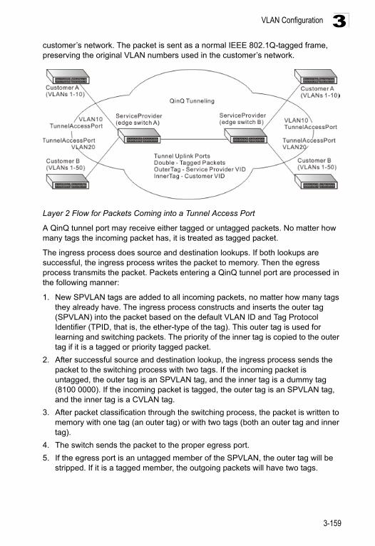
VLAN Configuration 3
customer’s network. The packet is sent as a normal IEEE 802.1Q-tagged frame, preserving the original VLAN numbers used in the customer’s network.Layer 2 Flow for Packets Coming into a Tunnel Access Port
A QinQ tunnel port may receive either tagged or untagged packets. No matter how many tags the incoming packet has, it is treated as tagged packet.
The ingress process does source and destination lookups. If both lookups are successful, the ingress process writes the packet to memory. Then the egress process transmits the packet. Packets entering a QinQ tunnel port are processed in the following manner:
1. New SPVLAN tags are added to all incoming packets, no matter how many tags they already have. The ingress process constructs and inserts the outer tag (SPVLAN) into the packet based on the default VLAN ID and Tag Protocol Identifier (TPID, that is, the ether-type of the tag). This outer tag is used for learning and switching packets. The priority of the inner tag is copied to the outer tag if it is a tagged or priority tagged packet.
2. After successful source and destination lookup, the ingress process sends the packet to the switching process with two tags. If the incoming packet is untagged, the outer tag is an SPVLAN tag, and the inner tag is a dummy tag (8100 0000). If the incoming packet is tagged, the outer tag is an SPVLAN tag, and the inner tag is a CVLAN tag.
3. After packet classification through the switching process, the packet is written to memory with one tag (an outer tag) or with two tags (both an outer tag and inner tag).
4. The switch sends the packet to the proper egress port.
5. If the egress port is an untagged member of the SPVLAN, the outer tag will be stripped. If it is a tagged member, the outgoing packets will have two tags.
3-159
Configuring the Switch3
Layer 2 Flow for Packets Coming into a Tunnel Uplink PortAn uplink port receives one of the following packets:
• Untagged
• One tag (CVLAN or SPVLAN)
• Double tag (CVLAN + SPVLAN)
The ingress process does source and destination lookups. If both lookups are successful, the ingress process writes the packet to memory. Then the egress process transmits the packet. Packets entering a QinQ uplink port are processed in the following manner:
1. If incoming packets are untagged, the PVID VLAN native tag is added.
2. If the ether-type of an incoming packet (single or double tagged) is not equal to the TPID of the uplink port, the VLAN tag is determined to be a Customer VLAN (CVLAN) tag. The uplink port’s PVID VLAN native tag is added to the packet. This outer tag is used for learning and switching packets within the service provider’s network. The TPID must be configured on a per port basis, and the verification cannot be disabled.
3. If the ether-type of an incoming packet (single or double tagged) is equal to the TPID of the uplink port, no new VLAN tag is added. If the uplink port is not the member of the outer VLAN of the incoming packets, the packet will be dropped when ingress filtering is enabled. If ingress filtering is not enabled, the packet will still be forwarded. If the VLAN is not listed in the VLAN table, the packet will be dropped.
4. After successful source and destination lookup, the packet is double tagged. The switch uses the TPID of 0x8100 to indicate that an incoming packet is double-tagged. If the outer tag of an incoming double-tagged packet is equal to the port TPID and the inner tag is 0x8100, it is treated as a double-tagged packet. If a single-tagged packet has 0x8100 as its TPID, and port TPID is not 0x8100, a new VLAN tag is added and it is also treated as double-tagged packet.
5. If the destination address lookup fails, the packet is sent to all member ports of the outer tag's VLAN.
6. After packet classification, the packet is written to memory for processing as a single-tagged or double-tagged packet.
7. The switch sends the packet to the proper egress port.
8. If the egress port is an untagged member of the SPVLAN, the outer tag will be stripped. If it is a tagged member, the outgoing packet will have two tags.
Configuration Limitations for QinQ
• The native VLAN of uplink ports should not be used as the SPVLAN. If the SPVLAN is the uplink port's native VLAN, the uplink port must be an untagged member of the SPVLAN. Then the outer SPVLAN tag will be stripped when the packets are sent out. Another reason is that it causes non-customer packets to be forwarded to the SPVLAN.
3-160
VLAN Configuration 3
• Static trunk port groups are compatible with QinQ tunnel ports as long as the QinQconfiguration is consistent within a trunk port group.
• The native VLAN (VLAN 1) is not normally added to transmitted frames. Avoiding using VLAN 1 as an SPVLAN tag for customer traffic to reduce the risk of misconfiguration. Instead, use VLAN 1 as a management VLAN instead of a data VLAN in the service provider network.
• There are some inherent incompatibilities between Layer 2 and Layer 3 switching:
- Tunnel ports do not support IP Access Control Lists.
- Layer 3 Quality of Service (QoS) and other QoS features containing Layer 3 information are not supported on tunnel ports.
- Spanning tree bridge protocol data unit (BPDU) filtering is automatically disabled on a tunnel port.
General Configuration Guidelines for QinQ
1. Configure the switch to QinQ mode (see "Enabling QinQ Tunneling on the Switch" on page 3-161).
2. Set the Tag Protocol Identifier (TPID) value of the tunnel access port. This step is required if the attached client is using a nonstandard 2-byte ethertype to identify 802.1Q tagged frames. The default ethertype value is 0x8100. (See "Enabling QinQ Tunneling on the Switch" on page 3-161.)
3. Create a Service Provider VLAN, also referred to as an SPVLAN (see "Creating VLANs" on page 3-150).
4. Configure the QinQ tunnel access port to 802.1Q Tunnel mode (see "Adding an Interface to a QinQ Tunnel" on page 3-162).
5. Configure the QinQ tunnel access port to join the SPVLAN as an untagged member (see "Adding Static Members to VLANs (VLAN Index)" on page 3-153).
6. Configure the SPVLAN ID as the native VID on the QinQ tunnel access port (see "Configuring VLAN Behavior for Interfaces" on page 3-156).
7. Configure the QinQ tunnel uplink port to 802.1Q Tunnel Uplink mode (see "Adding an Interface to a QinQ Tunnel" on page 3-162).
8. Configure the QinQ tunnel uplink port to join the SPVLAN as a tagged member (see "Adding Static Members to VLANs (VLAN Index)" on page 3-153).
Enabling QinQ Tunneling on the SwitchThe switch can be configured to operate in normal VLAN mode or IEEE 802.1Q (QinQ) tunneling mode which is used for passing Layer 2 traffic across a service provider’s metropolitan area network. You can also globally set the Tag Protocol Identifier (TPID) value of the tunnel port if the attached client is using a nonstandard 2-byte ethertype to identify 802.1Q tagged frames.
Command Usage
• Use the TPID field to set a custom 802.1Q ethertype value on the selected interface. This feature allows the switch to interoperate with third-party switches that do not use the standard 0x8100 ethertype to identify 802.1Q-tagged frames. For example, if 0x1234 is set as the custom 802.1Q ethertype on a trunk port,
3-161
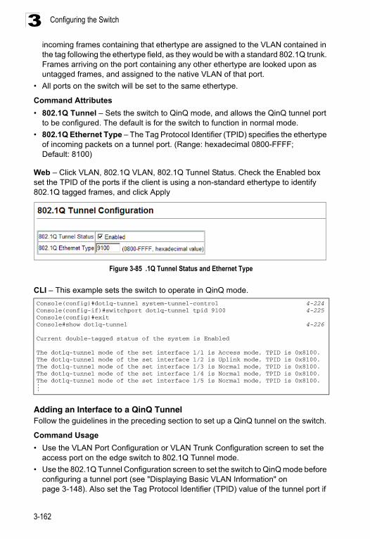
Configuring the Switch3
incoming frames containing that ethertype are assigned to the VLAN contained in the tag following the ethertype field, as they would be with a standard 802.1Q trunk. Frames arriving on the port containing any other ethertype are looked upon as untagged frames, and assigned to the native VLAN of that port.• All ports on the switch will be set to the same ethertype.
Command Attributes
• 802.1Q Tunnel – Sets the switch to QinQ mode, and allows the QinQ tunnel port to be configured. The default is for the switch to function in normal mode.
• 802.1Q Ethernet Type – The Tag Protocol Identifier (TPID) specifies the ethertype of incoming packets on a tunnel port. (Range: hexadecimal 0800-FFFF; Default: 8100)
Web – Click VLAN, 802.1Q VLAN, 802.1Q Tunnel Status. Check the Enabled box set the TPID of the ports if the client is using a non-standard ethertype to identify 802.1Q tagged frames, and click Apply
Figure 3-85 .1Q Tunnel Status and Ethernet Type
CLI – This example sets the switch to operate in QinQ mode.
Adding an Interface to a QinQ TunnelFollow the guidelines in the preceding section to set up a QinQ tunnel on the switch.
Command Usage
• Use the VLAN Port Configuration or VLAN Trunk Configuration screen to set the access port on the edge switch to 802.1Q Tunnel mode.
• Use the 802.1Q Tunnel Configuration screen to set the switch to QinQ mode before configuring a tunnel port (see "Displaying Basic VLAN Information" on page 3-148). Also set the Tag Protocol Identifier (TPID) value of the tunnel port if
Console(config)#dot1q-tunnel system-tunnel-control 4-224Console(config-if)#switchport dot1q-tunnel tpid 9100 4-225Console(config)#exitConsole#show dot1q-tunnel 4-226
Current double-tagged status of the system is Enabled
The dot1q-tunnel mode of the set interface 1/1 is Access mode, TPID is 0x8100.The dot1q-tunnel mode of the set interface 1/2 is Uplink mode, TPID is 0x8100.The dot1q-tunnel mode of the set interface 1/3 is Normal mode, TPID is 0x8100.The dot1q-tunnel mode of the set interface 1/4 is Normal mode, TPID is 0x8100.The dot1q-tunnel mode of the set interface 1/5 is Normal mode, TPID is 0x8100....
3-162
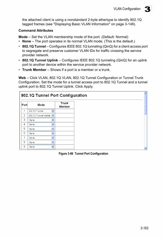
VLAN Configuration 3
the attached client is using a nonstandard 2-byte ethertype to identify 802.1Q tagged frames (see "Displaying Basic VLAN Information" on page 3-148).Command Attributes
Mode – Set the VLAN membership mode of the port. (Default: Normal)• None – The port operates in its normal VLAN mode. (This is the default.)
• 802.1Q Tunnel – Configures IEEE 802.1Q tunneling (QinQ) for a client access port to segregate and preserve customer VLAN IDs for traffic crossing the service provider network.
• 802.1Q Tunnel Uplink – Configures IEEE 802.1Q tunneling (QinQ) for an uplink port to another device within the service provider network.
• Trunk Member – Shows if a port is a member or a trunk.
Web – Click VLAN, 802.1Q VLAN, 802.1Q Tunnel Configuration or Tunnel Trunk Configuration. Set the mode for a tunnel access port to 802.1Q Tunnel and a tunnel uplink port to 802.1Q Tunnel Uplink. Click Apply.
Figure 3-86 Tunnel Port Configuration
3-163
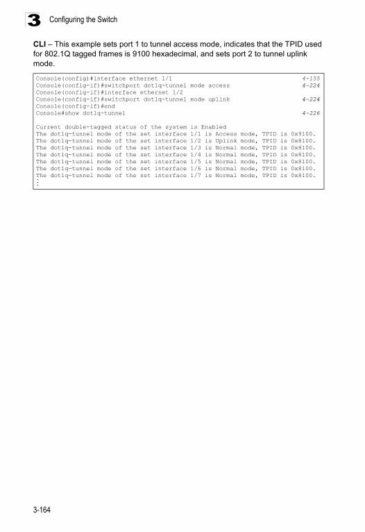
Configuring the Switch3
CLI – This example sets port 1 to tunnel access mode, indicates that the TPID used for 802.1Q tagged frames is 9100 hexadecimal, and sets port 2 to tunnel uplink mode.Console(config)#interface ethernet 1/1 4-155Console(config-if)#switchport dot1q-tunnel mode access 4-224Console(config-if)#interface ethernet 1/2Console(config-if)#switchport dot1q-tunnel mode uplink 4-224Console(config-if)#endConsole#show dot1q-tunnel 4-226
Current double-tagged status of the system is EnabledThe dot1q-tunnel mode of the set interface 1/1 is Access mode, TPID is 0x9100.The dot1q-tunnel mode of the set interface 1/2 is Uplink mode, TPID is 0x8100.The dot1q-tunnel mode of the set interface 1/3 is Normal mode, TPID is 0x8100.The dot1q-tunnel mode of the set interface 1/4 is Normal mode, TPID is 0x8100.The dot1q-tunnel mode of the set interface 1/5 is Normal mode, TPID is 0x8100.The dot1q-tunnel mode of the set interface 1/6 is Normal mode, TPID is 0x8100.The dot1q-tunnel mode of the set interface 1/7 is Normal mode, TPID is 0x8100....
3-164
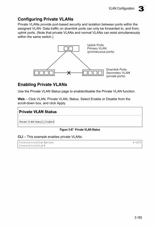
VLAN Configuration 3
Configuring Private VLANs Private VLANs provide port-based security and isolation between ports within the assigned VLAN. Data traffic on downlink ports can only be forwarded to, and from, uplink ports. (Note that private VLANs and normal VLANs can exist simultaneously within the same switch.)Enabling Private VLANs
Use the Private VLAN Status page to enable/disable the Private VLAN function.
Web – Click VLAN, Private VLAN, Status. Select Enable or Disable from the scroll-down box, and click Apply.
Figure 3-87 Private VLAN Status
CLI – This example enables private VLANs.
Console(config)#pvlan 4-209Console(config)#
3-165
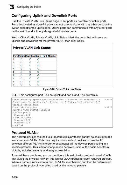
Configuring the Switch3
Configuring Uplink and Downlink PortsUse the Private VLAN Link Status page to set ports as downlink or uplink ports. Ports designated as downlink ports can not communicate with any other ports on the switch except for the uplink ports. Uplink ports can communicate with any other ports on the switch and with any designated downlink ports.Web – Click VLAN, Private VLAN, Link Status. Mark the ports that will serve as uplinks and downlinks for the private VLAN, then click Apply.
Figure 3-88 Private VLAN Link Status
CLI – This configures port 3 as an uplink and port 5 and 6 as downlinks.
Protocol VLANs The network devices required to support multiple protocols cannot be easily grouped into a common VLAN. This may require non-standard devices to pass traffic between different VLANs in order to encompass all the devices participating in a specific protocol. This kind of configuration deprives users of the basic benefits of VLANs, including security and easy accessibility.
To avoid these problems, you can configure this switch with protocol-based VLANs that divide the physical network into logical VLAN groups for each required protocol. When a frame is received at a port, its VLAN membership can then be determined based on the protocol type being used by the inbound packets.
Console(config)#pvlan up-link ethernet 1/3 down-link ethernet 1/5 4-228Console(config)#pvlan up-link ethernet 1/3 down-link ethernet 1/6Console(config)#endConsole#show pvlan 4-215Private VLAN status: EnabledUp-link port: Ethernet 1/3Down-link port: Ethernet 1/5 Ethernet 1/6Console#
3-166
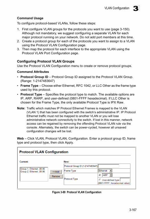
VLAN Configuration 3
Command UsageTo configure protocol-based VLANs, follow these steps:
1. First configure VLAN groups for the protocols you want to use (page 3-150). Although not mandatory, we suggest configuring a separate VLAN for each major protocol running on your network. Do not add port members at this time.
2. Create a protocol group for each of the protocols you want to assign to a VLAN using the Protocol VLAN Configuration page.
3. Then map the protocol for each interface to the appropriate VLAN using the Protocol VLAN Port Configuration page.
Configuring Protocol VLAN GroupsUse the Protocol VLAN Configuration menu to create or remove protocol groups.
Command Attributes
• Protocol Group ID – Protocol Group ID assigned to the Protocol VLAN Group. (Range: 1-2147483647)
• Frame Type – Choose either Ethernet, RFC 1042, or LLC Other as the frame type used by this protocol.
• Protocol Type – Specifies the protocol type to match. The available options are IP, ARP, RARP, and user-defined (0801-FFFF hexadecimal). If LLC Other is chosen for the Frame Type, the only available Protocol Type is IPX Raw.
Note: Traffic which matches IP Protocol Ethernet Frames is mapped to the VLAN (VLAN 1) that has been configured with the switch’s administrative IP. IP Protocol Ethernet traffic must not be mapped to another VLAN or you will lose administrative network connectivity to the switch. If lost in this manner, network access can be regained by removing the offending Protocol VLAN rule via the console. Alternately, the switch can be power-cycled, however all unsaved configuration changes will be lost.
Web – Click VLAN, Protocol VLAN, Configuration. Enter a protocol group ID, frame type and protocol type, then click Apply.
Figure 3-89 Protocol VLAN Configuration
3-167
Configuring the Switch3
CLI – This example creates protocol group 1 for Ethernet frames using the IP protocol, and group 2 for Ethernet frames using the ARP protocol.Mapping Protocols to VLANs
Use the Protocol VLAN Port Configuration menu to map a Protocol VLAN Group to a VLAN. Map a protocol group to a VLAN for each interface that will participate in the group.
Command Usage
• When creating a protocol-based VLAN, only assign interfaces using this configuration screen. If you assign interfaces using any of the other VLAN menus such as the VLAN Static Table (page 3-153) or VLAN Static Membership by Port menu (page 3-155), these interfaces will admit traffic of any protocol type into the associated VLAN.
• When a frame enters a port that has been assigned to a protocol VLAN, it is processed in the following manner:
- If the frame is tagged, it will be processed according to the standard rules applied to tagged frames.
- If the frame is untagged and the protocol type matches, the frame is forwarded to the appropriate VLAN.
- If the frame is untagged but the protocol type does not match, the frame is forwarded to the default VLAN for this interface.
Command Attributes
• Interface – Port or Trunk identifier.
• Protocol Group ID – Protocol Group ID assigned to the Protocol VLAN Group. (Range: 1-2147483647)
• VLAN ID – VLAN to which matching protocol traffic is forwarded. (Range: 1-4094)
Console(config)#protocol-vlan protocol-group 1 add frame-type ethernet protocol-type ip 4-235
Console(config)#protocol-vlan protocol-group 2 add frame-type ethernet protocol-type arp
Console(config)#
3-168
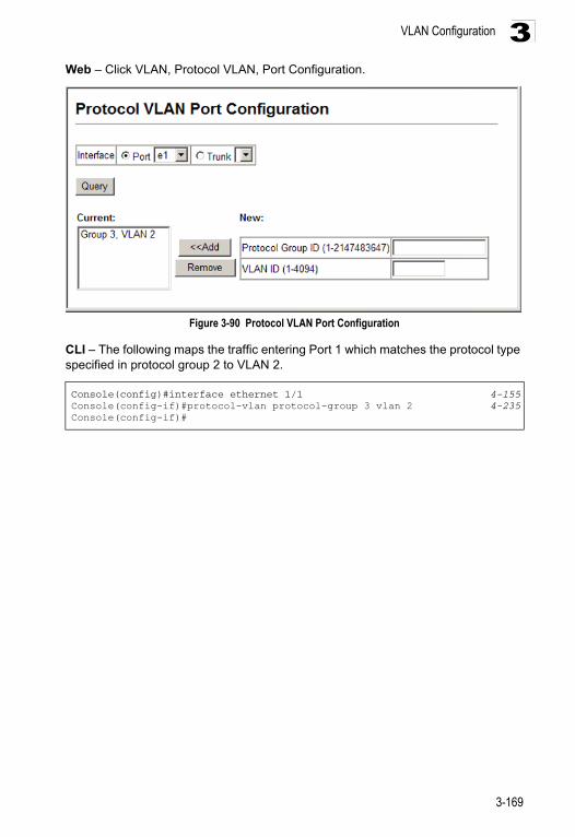
VLAN Configuration 3
Web – Click VLAN, Protocol VLAN, Port Configuration.Figure 3-90 Protocol VLAN Port Configuration
CLI – The following maps the traffic entering Port 1 which matches the protocol type specified in protocol group 2 to VLAN 2.
Console(config)#interface ethernet 1/1 4-155Console(config-if)#protocol-vlan protocol-group 3 vlan 2 4-235Console(config-if)#
3-169
Configuring the Switch3
Class of Service ConfigurationClass of Service (CoS) allows you to specify which data packets have greater precedence when traffic is buffered in the switch due to congestion. This switch supports CoS with four priority queues for each port. Data packets in a port’s high-priority queue will be transmitted before those in the lower-priority queues. You can set the default priority for each interface, and configure the mapping of frame priority tags to the switch’s priority queues.Layer 2 Queue Settings
Setting the Default Priority for Interfaces
You can specify the default port priority for each interface on the switch. All untagged packets entering the switch are tagged with the specified default port priority, and then sorted into the appropriate priority queue at the output port.
Command Usage
• This switch provides four priority queues for each port. It uses Weighted Round Robin to prevent head-of-queue blockage.
• The default priority applies for an untagged frame received on a port set to accept all frame types (i.e, receives both untagged and tagged frames). This priority does not apply to IEEE 802.1Q VLAN tagged frames. If the incoming frame is an IEEE 802.1Q VLAN tagged frame, the IEEE 802.1p User Priority bits will be used.
• If the output port is an untagged member of the associated VLAN, these frames are stripped of all VLAN tags prior to transmission.
3-170
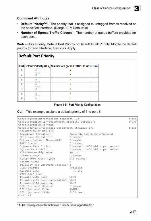
Class of Service Configuration 3
Command Attributes• Default Priority14 – The priority that is assigned to untagged frames received on the specified interface. (Range: 0-7; Default: 0)
• Number of Egress Traffic Classes – The number of queue buffers provided for each port.
Web – Click Priority, Default Port Priority or Default Trunk Priority. Modify the default priority for any interface, then click Apply.
Figure 3-91 Port Priority Configuration
CLI – This example assigns a default priority of 5 to port 3.
14. CLI displays this information as “Priority for untagged traffic.”
Console(config)#interface ethernet 1/3 4-155Console(config-if)#switchport priority default 5 4-239Console(config-if)#endConsole#show interfaces switchport ethernet 1/3 4-165Information of Eth 1/3 Broadcast Threshold: Enabled, 500 packets/second Multicast Threshold: Disabled Unknown Unicast Threshold: Disabled LACP Status: Disabled Ingress Rate Limit: Disabled, 1000 Mbits per second Egress Rate Limit: Disabled, 1000 Mbits per second VLAN Membership Mode: Hybrid Ingress Rule: Disabled Acceptable Frame Type: All frames Native VLAN: 1 Priority for Untagged Traffic: 5 GVRP Status: Disabled Allowed VLAN: 1(u), Forbidden VLAN: Private-VLAN Mode: NONE Private-VLAN host-association: NONE Private-VLAN Mapping: NONE 802.1Q-tunnel Status: Disable 802.1Q-tunnel Mode: NORMAL 802.1Q-tunnel TPID: 8100(Hex)Console#
3-171
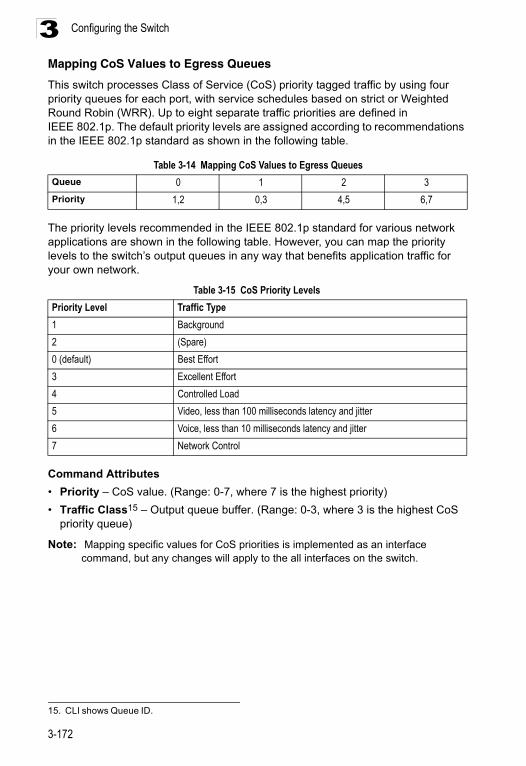
Configuring the Switch3
Mapping CoS Values to Egress QueuesThis switch processes Class of Service (CoS) priority tagged traffic by using four priority queues for each port, with service schedules based on strict or Weighted Round Robin (WRR). Up to eight separate traffic priorities are defined in IEEE 802.1p. The default priority levels are assigned according to recommendations in the IEEE 802.1p standard as shown in the following table.
The priority levels recommended in the IEEE 802.1p standard for various network applications are shown in the following table. However, you can map the priority levels to the switch’s output queues in any way that benefits application traffic for your own network.
Command Attributes
• Priority – CoS value. (Range: 0-7, where 7 is the highest priority)
• Traffic Class15 – Output queue buffer. (Range: 0-3, where 3 is the highest CoS priority queue)
Note: Mapping specific values for CoS priorities is implemented as an interface command, but any changes will apply to the all interfaces on the switch.
Table 3-14 Mapping CoS Values to Egress Queues
Queue 0 1 2 3
Priority 1,2 0,3 4,5 6,7
Table 3-15 CoS Priority Levels
Priority Level Traffic Type
1 Background
2 (Spare)
0 (default) Best Effort
3 Excellent Effort
4 Controlled Load
5 Video, less than 100 milliseconds latency and jitter
6 Voice, less than 10 milliseconds latency and jitter
7 Network Control
15. CLI shows Queue ID.
3-172
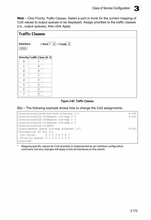
Class of Service Configuration 3
Web – Click Priority, Traffic Classes. Select a port or trunk for the current mapping of CoS values to output queues to be displayed. Assign priorities to the traffic classes (i.e., output queues), then click Apply.Figure 3-92 Traffic Classes
CLI – The following example shows how to change the CoS assignments.
* Mapping specific values for CoS priorities is implemented as an interface configuration command, but any changes will apply to the all interfaces on the switch.
Console(config)#interface ethernet 1/1 4-155Console(config-if)#queue cos-map 0 0 4-241Console(config-if)#queue cos-map 1 1Console(config-if)#queue cos-map 2 2Console(config-if)#endConsole#show queue cos-map ethernet 1/1 4-243Information of Eth 1/1 CoS Value: 0 1 2 3 4 5 6 7 Priority Queue: 0 1 2 1 2 2 3 3Console#
3-173
Configuring the Switch3
Selecting the Queue ModeYou can set the switch to service the queues based on a strict rule that requires all traffic in a higher priority queue to be processed before lower priority queues are serviced, or use Weighted Round-Robin (WRR) queuing that specifies a relative weight of each queue.
Command Usage
• Strict priority requires all traffic in a higher priority queue to be processed before lower priority queues are serviced.
• WRR uses a relative weighting for each queue which determines the amount of packets the switch transmits every time it services each queue before moving on to the next queue. Thus, a queue weighted 8 will be allowed to transmit up to 8 packets, after which the next lower priority queue will be serviced according to it’s weighting. This prevents the head-of-line blocking that can occur with strict priority queuing.
Command Attributes
• WRR - Weighted Round-Robin shares bandwidth at the egress ports by using scheduling weights with default values of 1, 2, 4, 8, for queues 0 through 3, respectively. (This is the default selection.)
• Strict - Services the egress queues in sequential order, transmitting all traffic in the higher priority queues before servicing lower priority queues.
Web – Click Priority, Queue Mode. Select Strict or WRR, then click Apply.
Figure 3-93 Queue Mode
CLI – The following sets the queue mode to WRR priority service mode.
Console(config)#queue mode wrr 4-239Console(config)#exitConsole#show queue mode 4-242Queue mode: wrrConsole#
3-174
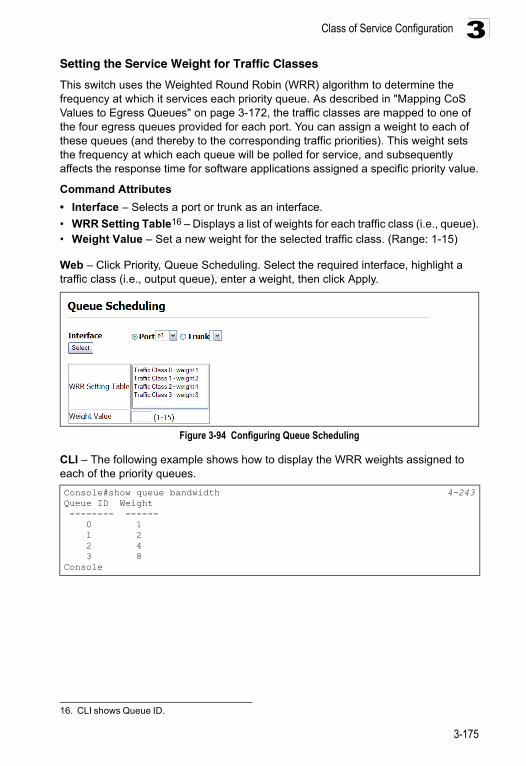
Class of Service Configuration 3
Setting the Service Weight for Traffic ClassesThis switch uses the Weighted Round Robin (WRR) algorithm to determine the frequency at which it services each priority queue. As described in "Mapping CoS Values to Egress Queues" on page 3-172, the traffic classes are mapped to one of the four egress queues provided for each port. You can assign a weight to each of these queues (and thereby to the corresponding traffic priorities). This weight sets the frequency at which each queue will be polled for service, and subsequently affects the response time for software applications assigned a specific priority value.
Command Attributes
• Interface – Selects a port or trunk as an interface.
• WRR Setting Table16 – Displays a list of weights for each traffic class (i.e., queue).• Weight Value – Set a new weight for the selected traffic class. (Range: 1-15)
Web – Click Priority, Queue Scheduling. Select the required interface, highlight a traffic class (i.e., output queue), enter a weight, then click Apply.
Figure 3-94 Configuring Queue Scheduling
CLI – The following example shows how to display the WRR weights assigned to each of the priority queues.
16. CLI shows Queue ID.
Console#show queue bandwidth 4-243Queue ID Weight -------- ------ 0 1 1 2 2 4 3 8Console
3-175
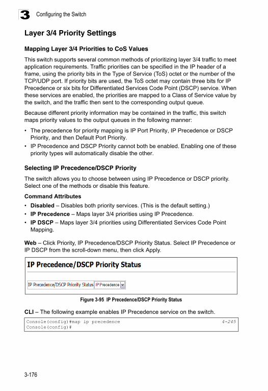
Configuring the Switch3
Layer 3/4 Priority SettingsMapping Layer 3/4 Priorities to CoS Values
This switch supports several common methods of prioritizing layer 3/4 traffic to meet application requirements. Traffic priorities can be specified in the IP header of a frame, using the priority bits in the Type of Service (ToS) octet or the number of the TCP/UDP port. If priority bits are used, the ToS octet may contain three bits for IP Precedence or six bits for Differentiated Services Code Point (DSCP) service. When these services are enabled, the priorities are mapped to a Class of Service value by the switch, and the traffic then sent to the corresponding output queue.
Because different priority information may be contained in the traffic, this switch maps priority values to the output queues in the following manner:
• The precedence for priority mapping is IP Port Priority, IP Precedence or DSCP Priority, and then Default Port Priority.
• IP Precedence and DSCP Priority cannot both be enabled. Enabling one of these priority types will automatically disable the other.
Selecting IP Precedence/DSCP Priority
The switch allows you to choose between using IP Precedence or DSCP priority. Select one of the methods or disable this feature.
Command Attributes
• Disabled – Disables both priority services. (This is the default setting.)
• IP Precedence – Maps layer 3/4 priorities using IP Precedence.
• IP DSCP – Maps layer 3/4 priorities using Differentiated Services Code Point Mapping.
Web – Click Priority, IP Precedence/DSCP Priority Status. Select IP Precedence or IP DSCP from the scroll-down menu, then click Apply.
Figure 3-95 IP Precedence/DSCP Priority Status
CLI – The following example enables IP Precedence service on the switch.
Console(config)#map ip precedence 4-245Console(config)#
3-176
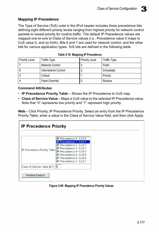
Class of Service Configuration 3
Mapping IP PrecedenceThe Type of Service (ToS) octet in the IPv4 header includes three precedence bits defining eight different priority levels ranging from highest priority for network control packets to lowest priority for routine traffic. The default IP Precedence values are mapped one-to-one to Class of Service values (i.e., Precedence value 0 maps to CoS value 0, and so forth). Bits 6 and 7 are used for network control, and the other bits for various application types. ToS bits are defined in the following table.
Command Attributes
• IP Precedence Priority Table – Shows the IP Precedence to CoS map.
• Class of Service Value – Maps a CoS value to the selected IP Precedence value. Note that “0” represents low priority and “7” represent high priority.
Web – Click Priority, IP Precedence Priority. Select an entry from the IP Precedence Priority Table, enter a value in the Class of Service Value field, and then click Apply.
Figure 3-96 Mapping IP Precedence Priority Values
Table 3-16 Mapping IP Precedence
Priority Level Traffic Type Priority Level Traffic Type
7 Network Control 3 Flash
6 Internetwork Control 2 Immediate
5 Critical 1 Priority
4 Flash Override 0 Routine
3-177
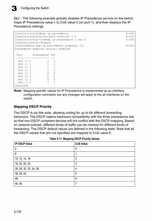
Configuring the Switch3
CLI – The following example globally enables IP Precedence service on the switch, maps IP Precedence value 1 to CoS value 0 (on port 1), and then displays the IP Precedence settings.Note: Mapping specific values for IP Precedence is implemented as an interface configuration command, but any changes will apply to the all interfaces on the switch.
Mapping DSCP Priority
The DSCP is six bits wide, allowing coding for up to 64 different forwarding behaviors. The DSCP retains backward compatibility with the three precedence bits so that non-DSCP compliant devices will not conflict with the DSCP mapping. Based on network policies, different kinds of traffic can be marked for different kinds of forwarding. The DSCP default values are defined in the following table. Note that all the DSCP values that are not specified are mapped to CoS value 0.
Console(config)#map ip precedence 4-245Console(config)#interface ethernet 1/1 4-155Console(config-if)#map ip precedence 1 cos 0 4-246Console(config-if)#endConsole#show map ip precedence ethernet 1/1 4-249Precedence mapping status: enabled
Port Precedence COS --------- ---------- --- Eth 1/ 1 0 0 Eth 1/ 1 1 0 Eth 1/ 1 2 2 Eth 1/ 1 3 3 Eth 1/ 1 4 4 Eth 1/ 1 5 5 Eth 1/ 1 6 6 Eth 1/ 1 7 7Console#
Table 3-17 Mapping DSCP Priority Values
IP DSCP Value CoS Value
0 0
8 1
10, 12, 14, 16 2
18, 20, 22, 24 3
26, 28, 30, 32, 34, 36 4
38, 40, 42 5
48 6
46, 56 7
3-178
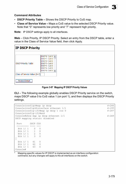
Class of Service Configuration 3
Command Attributes• DSCP Priority Table – Shows the DSCP Priority to CoS map.
• Class of Service Value – Maps a CoS value to the selected DSCP Priority value. Note that “0” represents low priority and “7” represent high priority.
Note: IP DSCP settings apply to all interfaces.
Web – Click Priority, IP DSCP Priority. Select an entry from the DSCP table, enter a value in the Class of Service Value field, then click Apply.
Figure 3-97 Mapping IP DSCP Priority Values
CLI – The following example globally enables DSCP Priority service on the switch, maps DSCP value 0 to CoS value 1 (on port 1), and then displays the DSCP Priority settings.
* Mapping specific values for IP DSCP is implemented as an interface configuration command, but any changes will apply to the all interfaces on the switch.
Console(config)#map ip dscp 4-246Console(config)#interface ethernet 1/1 4-155Console(config-if)#map ip dscp 1 cos 0 4-247Console(config-if)#endConsole#show map ip dscp ethernet 1/1 4-249DSCP mapping status: disabled
Port DSCP COS --------- ---- --- Eth 1/ 1 0 0 Eth 1/ 1 1 0 Eth 1/ 1 2 0 Eth 1/ 1 3 0... Eth 1/ 1 61 0 Eth 1/ 1 62 0 Eth 1/ 1 63 0Console#
3-179
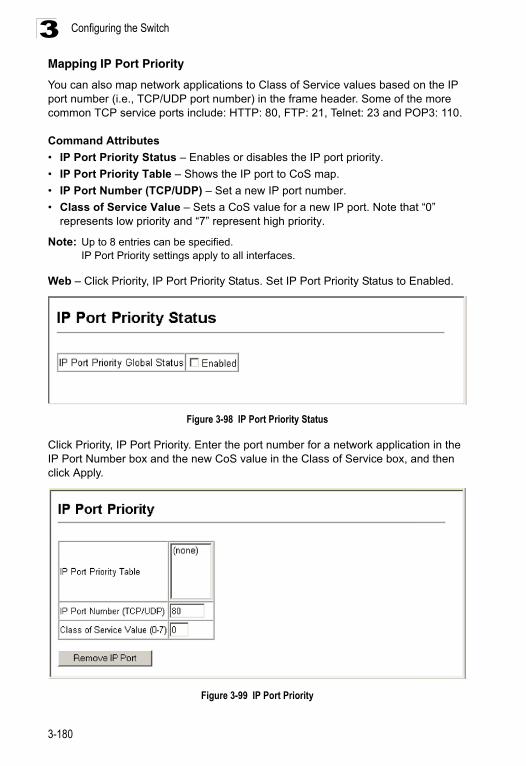
Configuring the Switch3
Mapping IP Port PriorityYou can also map network applications to Class of Service values based on the IP port number (i.e., TCP/UDP port number) in the frame header. Some of the more common TCP service ports include: HTTP: 80, FTP: 21, Telnet: 23 and POP3: 110.
Command Attributes
• IP Port Priority Status – Enables or disables the IP port priority.
• IP Port Priority Table – Shows the IP port to CoS map.
• IP Port Number (TCP/UDP) – Set a new IP port number.
• Class of Service Value – Sets a CoS value for a new IP port. Note that “0” represents low priority and “7” represent high priority.
Note: Up to 8 entries can be specified.IP Port Priority settings apply to all interfaces.
Web – Click Priority, IP Port Priority Status. Set IP Port Priority Status to Enabled.
Figure 3-98 IP Port Priority Status
Click Priority, IP Port Priority. Enter the port number for a network application in the IP Port Number box and the new CoS value in the Class of Service box, and then click Apply.
Figure 3-99 IP Port Priority
3-180
Quality of Service 3
CLI* – The following example globally enables IP Port Priority service on the switch, maps HTTP traffic on port 5 to CoS value 0, and then displays all the IP Port Priority settings for that port.* Mapping specific values for IP Port Priority is implemented as an interface configuration command, but any changes will apply to the all interfaces on the switch.
Quality of Service The commands described in this section are used to configure Quality of Service (QoS) classification criteria and service policies. Differentiated Services (DiffServ) provides policy-based management mechanisms used for prioritizing network resources to meet the requirements of specific traffic types on a per hop basis. Each packet is classified upon entry into the network based on access lists, IP Precedence, DSCP values, or VLAN lists. Using access lists allows you select traffic based on Layer 2, Layer 3, or Layer 4 information contained in each packet. Based on configured network policies, different kinds of traffic can be marked for different kinds of forwarding.
All switches or routers that access the Internet rely on class information to provide the same forwarding treatment to packets in the same class. Class information can be assigned by end hosts, or switches or routers along the path. Priority can then be assigned based on a general policy, or a detailed examination of the packet. However, note that detailed examination of packets should take place close to the network edge so that core switches and routers are not overloaded.
Switches and routers along the path can use class information to prioritize the resources allocated to different traffic classes. The manner in which an individual device handles traffic in the DiffServ architecture is called per-hop behavior. All devices along a path should be configured in a consistent manner to construct a consistent end-to-end QoS solution.
Notes: 1. You can configure up to 16 rules per Class Map. You can also include multiple classes in a Policy Map.
2. You should create a Class Map before creating a Policy Map. Otherwise, you will not be able to select a Class Map from the Policy Rule Settings screen (see page 3-187).
3. Due to a chip limitation, IP Source Guard and Quality of Service (for IP-related QoS functions) cannot be enabled at the same time.
Console(config)#map ip port 4-244Console(config)#interface ethernet 1/5Console(config-if)#map ip port 80 cos 0 4-245Console(config-if)#endConsole#show map ip port ethernet 1/5 4-248TCP port mapping status: disabled
Port Port no. COS --------- -------- --- Eth 1/ 5 80 0Console#
3-181
Configuring the Switch3
Configuring Quality of Service Parameters To create a service policy for a specific category or ingress traffic, follow these steps:1. Use the “Class Map” to designate a class name for a specific category of traffic. 2. Edit the rules for each class to specify a type of traffic based on an access list, a
DSCP or IP Precedence value, or a VLAN.3. Use the “Policy Map” to designate a policy name for a specific manner in which
ingress traffic will be handled. 4. Add one or more classes to the Policy Map. Assign policy rules to each class by
“setting” the QoS value to be assigned to the matching traffic class. The policy rule can also be configured to monitor the average flow and burst rate, and drop any traffic that exceeds the specified rate, or just reduce the DSCP service level for traffic exceeding the specified rate.
5. Use the “Service Policy” to assign a policy map to a specific interface.
Configuring a Class MapA class map is used for matching packets to a specified class.
Command Usage
• To configure a Class Map, follow these steps:
- Open the Class Map page, and click Add Class. - When the Class Configuration page opens, fill in the “Class Name” field, and
click Add. - When the Match Class Settings page opens, specify type of traffic for this class
based on an access list, a DSCP or IP Precedence value, or a VLAN, and click the Add button next to the field for the selected traffic criteria. You can specify up to 16 items to match when assigning ingress traffic to a class map.
• The class map is used with a policy map (page 3-185) to create a service policy (page 3-188) for a specific interface that defines packet classification, service tagging, and bandwidth policing. Note that one or more class maps can be assigned to a policy map.
Command Attributes
Class Map
• Modify Name and Description – Configures the name and a brief description of a class map. (Range: 1-16 characters for the name; 1-64 characters for the description)
• Edit Rules – Opens the “Match Class Settings” page for the selected class entry. Modify the criteria used to classify ingress traffic on this page.
• Add Class – Opens the “Class Configuration” page. Enter a class name and description on this page, and click Add to open the “Match Class Settings” page. Enter the criteria used to classify ingress traffic on this page.
• Remove Class – Removes the selected class.
3-182
Quality of Service 3
Class Configuration• Class Name – Name of the class map. (Range: 1-16 characters)
• Type – Only one match command is permitted per class map, so the match-any field refers to the criteria specified by the lone match command.
• Description – A brief description of a class map. (Range: 1-64 characters)
• Add – Adds the specified class.
• Back – Returns to previous page with making any changes.
Match Class Settings
• Class Name – List of class maps.
• ACL List – Name of an access control list. Any type of ACL can be specified, including standard or extended IP ACLs and MAC ACLs. (Range: 1-16 characters)
• IP DSCP – A DSCP value. (Range: 0-63)
• IP Precedence – An IP Precedence value. (Range: 0-7)
• VLAN – A VLAN. (Range:1-4094)
• Add – Adds specified criteria to the class. Up to 16 items are permitted per class.
• Remove – Deletes the selected criteria from the class.
3-183
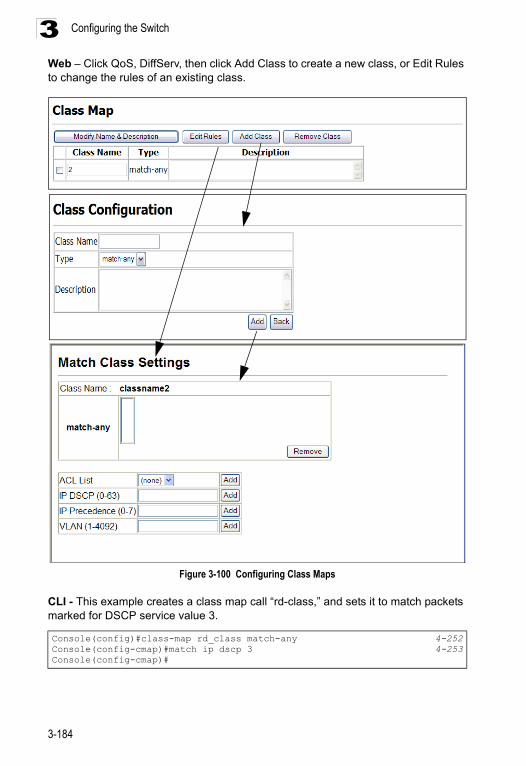
Configuring the Switch3
Web – Click QoS, DiffServ, then click Add Class to create a new class, or Edit Rules to change the rules of an existing class.Figure 3-100 Configuring Class Maps
CLI - This example creates a class map call “rd-class,” and sets it to match packets marked for DSCP service value 3.
Console(config)#class-map rd_class match-any 4-252Console(config-cmap)#match ip dscp 3 4-253Console(config-cmap)#
3-184
Quality of Service 3
Creating QoS PoliciesThis function creates a policy map that can be attached to multiple interfaces.Command Usage
• To configure a Policy Map, follow these steps:
- Create a Class Map as described on page 3-182.- Open the Policy Map page, and click Add Policy. - When the Policy Configuration page opens, fill in the “Policy Name” field, and
click Add. - When the Policy Rule Settings page opens, select a class name from the
scroll-down list (Class Name field). Configure a policy for traffic that matches criteria defined in this class by setting the quality of service that an IP packet will receive (in the Action field), defining the maximum throughput and burst rate (in the Meter field), and the action that results from a policy violation (in the Exceed field). Then finally click Add to register the new policy.
• A policy map can contain multiple class statements that can be applied to the same interface with the Service Policy Settings (page 3-188). You can configure up to 64 policers (i.e., meters or class maps) for each of the following access list types: MAC ACL, IP ACL (including Standard ACL and Extended ACL). Also, note that the maximum number of classes that can be applied to a policy map is 16.
Policing is based on a token bucket, where bucket depth (i.e., the maximum burst before the bucket overflows) is by specified the “Burst” field, and the average rate tokens are removed from the bucket is by specified by the “Rate” option.
• After using the policy map to define packet classification, service tagging, and bandwidth policing, it must be assigned to a specific interface by a service policy (page 3-188) to take effect.
Command Attributes
Policy Map
• Modify Name and Description – Configures the name and a brief description of a policy map. (Range: 1-16 characters for the name; 1-64 characters for the description)
• Edit Classes – Opens the “Policy Rule Settings” page for the selected class entry. Modify the criteria used to service ingress traffic on this page.
• Add Policy – Opens the “Policy Configuration” page. Enter a policy name and description on this page, and click Add to open the “Policy Rule Settings” page. Enter the criteria used to service ingress traffic on this page.
• Remove Policy – Deletes a specified policy.
Policy Configuration
• Policy Name – Name of policy map. (Range: 1-16 characters)
• Description – A brief description of a policy map. (Range: 1-64 characters)
• Add – Adds the specified policy.
• Back – Returns to previous page with making any changes.
3-185
Configuring the Switch3
Policy Rule Settings- Class Settings -
• Class Name – Name of class map.
• Action – Shows the service provided to ingress traffic by setting a CoS, DSCP, or IP Precedence value in a matching packet (as specified in Match Class Settings on page 3-182).
• Meter – The maximum throughput and burst rate.
- Rate (kbps) – Rate in kilobits per second.- Burst (byte) – Burst in bytes.
• Exceed Action – Specifies whether the traffic that exceeds the specified rate will be dropped or the DSCP service level will be reduced.
• Remove Class – Deletes a class.
- Policy Options -
• Class Name – Name of class map.
• Action – Configures the service provided to ingress traffic by setting a CoS, DSCP, or IP Precedence value in a matching packet (as specified in Match Class Settings on page 3-182). (Range - CoS: 0-7, DSCP: 0-63, IP Precedence: 0-7)
• Meter – Check this to define the maximum throughput, burst rate, and the action that results from a policy violation.
- Rate (kbps) – Rate in kilobits per second. (Range: 1-100000 kbps or maximum port speed, whichever is lower)
- Burst (byte) – Burst in bytes. (Range: 64-1522)
• Exceed – Specifies whether the traffic that exceeds the specified rate or burst will be dropped or the DSCP service level will be reduced.
- Set – Decreases DSCP priority for out of conformance traffic. (Range: 0-63).- Drop – Drops out of conformance traffic.
• Add – Adds the specified criteria to the policy map.
3-186
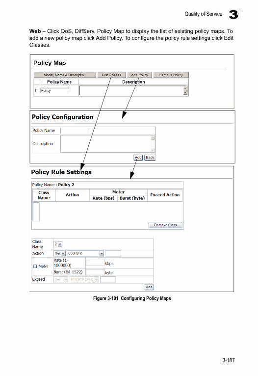
Quality of Service 3
Web – Click QoS, DiffServ, Policy Map to display the list of existing policy maps. To add a new policy map click Add Policy. To configure the policy rule settings click Edit Classes.Figure 3-101 Configuring Policy Maps
3-187
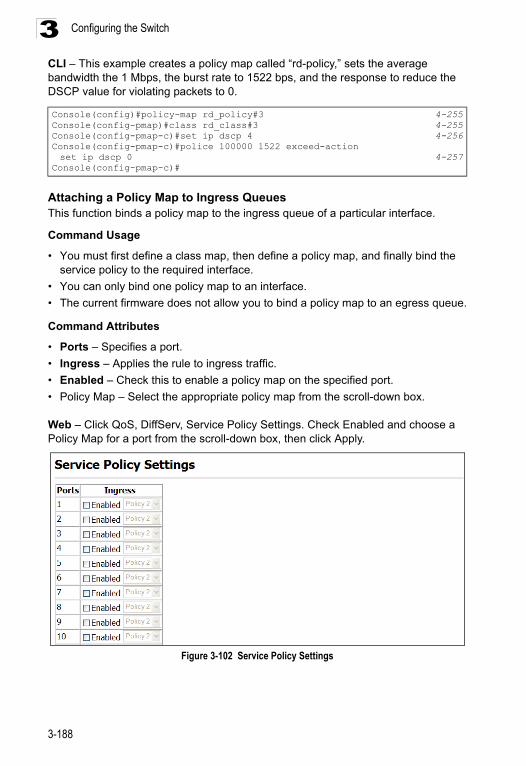
Configuring the Switch3
CLI – This example creates a policy map called “rd-policy,” sets the average bandwidth the 1 Mbps, the burst rate to 1522 bps, and the response to reduce the DSCP value for violating packets to 0.Attaching a Policy Map to Ingress QueuesThis function binds a policy map to the ingress queue of a particular interface.
Command Usage
• You must first define a class map, then define a policy map, and finally bind the service policy to the required interface.
• You can only bind one policy map to an interface.
• The current firmware does not allow you to bind a policy map to an egress queue.
Command Attributes
• Ports – Specifies a port.
• Ingress – Applies the rule to ingress traffic.
• Enabled – Check this to enable a policy map on the specified port.
• Policy Map – Select the appropriate policy map from the scroll-down box.
Web – Click QoS, DiffServ, Service Policy Settings. Check Enabled and choose a Policy Map for a port from the scroll-down box, then click Apply.
Figure 3-102 Service Policy Settings
Console(config)#policy-map rd_policy#3 4-255Console(config-pmap)#class rd_class#3 4-255Console(config-pmap-c)#set ip dscp 4 4-256Console(config-pmap-c)#police 100000 1522 exceed-action set ip dscp 0 4-257
Console(config-pmap-c)#
3-188
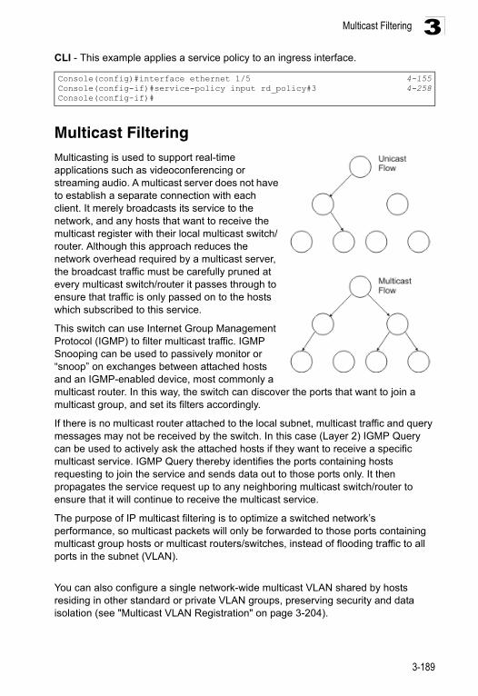
Multicast Filtering 3
CLI - This example applies a service policy to an ingress interface.Multicast Filtering Multicasting is used to support real-time applications such as videoconferencing or streaming audio. A multicast server does not have to establish a separate connection with each client. It merely broadcasts its service to the network, and any hosts that want to receive the multicast register with their local multicast switch/router. Although this approach reduces the network overhead required by a multicast server, the broadcast traffic must be carefully pruned at every multicast switch/router it passes through to ensure that traffic is only passed on to the hosts which subscribed to this service.
This switch can use Internet Group Management Protocol (IGMP) to filter multicast traffic. IGMP Snooping can be used to passively monitor or “snoop” on exchanges between attached hosts and an IGMP-enabled device, most commonly a multicast router. In this way, the switch can discover the ports that want to join a multicast group, and set its filters accordingly.
If there is no multicast router attached to the local subnet, multicast traffic and query messages may not be received by the switch. In this case (Layer 2) IGMP Query can be used to actively ask the attached hosts if they want to receive a specific multicast service. IGMP Query thereby identifies the ports containing hosts requesting to join the service and sends data out to those ports only. It then propagates the service request up to any neighboring multicast switch/router to ensure that it will continue to receive the multicast service.
The purpose of IP multicast filtering is to optimize a switched network’s performance, so multicast packets will only be forwarded to those ports containing multicast group hosts or multicast routers/switches, instead of flooding traffic to all ports in the subnet (VLAN).
You can also configure a single network-wide multicast VLAN shared by hosts residing in other standard or private VLAN groups, preserving security and data isolation (see "Multicast VLAN Registration" on page 3-204).
Console(config)#interface ethernet 1/5 4-155Console(config-if)#service-policy input rd_policy#3 4-258Console(config-if)#
3-189
Configuring the Switch3
Layer 2 IGMP (Snooping and Query)IGMP Snooping and Query – If multicast routing is not supported on other switches in your network, you can use IGMP Snooping and Query (page 3-191) to monitor IGMP service requests passing between multicast clients and servers, and dynamically configure the switch ports which need to forward multicast traffic.
When using IGMPv3 snooping, service requests from IGMP Version 1, 2 or 3 hosts are all forwarded to the upstream router as IGMPv3 reports. The primary enhancement provided by IGMPv3 snooping is in keeping track of information about the specific multicast sources which downstream IGMPv3 hosts have requested or refused. The switch maintains information about both multicast groups and channels, where a group indicates a multicast flow for which the hosts have not requested a specific source (the only option for IGMPv1 and v2 hosts unless statically configured on the switch), and a channel indicates a flow for which the hosts have requested service from a specific source.
Only IGMPv3 hosts can request service from a specific multicast source. When downstream hosts request service from a specific source for a multicast service, these sources are all placed in the Include list, and traffic is forwarded to the hosts from each of these sources. IGMPv3 hosts may also request that service be forwarded from all sources except for those specified. In this case, traffic is filtered from sources in the Exclude list, and forwarded from all other available sources.
Notes: 1. When the switch is configured to use IGMPv3 snooping, the snooping version may be downgraded to version 2 or version 1, depending on the version of the IGMP query packets detected on each VLAN.
2. IGMP snooping will not function unless a multicast router port is enabled on the switch. This can be accomplished in one of two ways. A static router port can be manually configured (see “Specifying Static Interfaces for a Multicast Router” on page 3-196). Using this method, the router port is never timed out, and will continue to function until explicitly removed. The other method relies on the switch to dynamically create multicast routing ports whenever multicast routing protocol packets or IGMP query packets are detected on a port.
3. A maximum of up to 255 multicast entries can be maintained for IGMP snooping, and 255 entries for Multicast Routing, when both of these features are enabled. If the table’s capacity is exceeded, the IGMPv3 snooping will not support multicast source filtering, but will forward multicast traffic from all relevant sources to the requesting hosts.
Static IGMP Router Interface – If IGMP snooping cannot locate the IGMP querier, you can manually designate a known IGMP querier (i.e., a multicast router/switch) connected over the network to an interface on your switch (page 3-196). This interface will then join all the current multicast groups supported by the attached router/switch to ensure that multicast traffic is passed to all appropriate interfaces within the switch.
3-190
Multicast Filtering 3
Static IGMP Host Interface – For multicast applications that you need to control more carefully, you can manually assign a multicast service to specific interfaces on the switch (page 3-198).Configuring IGMP Snooping and Query Parameters
You can configure the switch to forward multicast traffic intelligently. Based on the IGMP query and report messages, the switch forwards traffic only to the ports that request multicast traffic. This prevents the switch from broadcasting the traffic to all ports and possibly disrupting network performance.
Command Usage
• IGMP Snooping – This switch can passively snoop on IGMP Query and Report packets transferred between IP multicast routers/switches and IP multicast host groups to identify the IP multicast group members. It simply monitors the IGMP packets passing through it, picks out the group registration information, and configures the multicast filters accordingly.
Note: Unknown multicast traffic is flooded to all ports in the VLAN for several seconds when first received. If a multicast router port exists on the VLAN, the traffic will be filtered by subjecting it to IGMP snooping. If no router port exists on the VLAN or the multicast filtering table is already full, the switch will continue flooding the traffic into the VLAN.
• IGMP Querier – A router, or multicast-enabled switch, can periodically ask their hosts if they want to receive multicast traffic. If there is more than one router/switch on the LAN performing IP multicasting, one of these devices is elected “querier” and assumes the role of querying the LAN for group members. It then propagates the service requests on to any upstream multicast switch/router to ensure that it will continue to receive the multicast service.
Note: Multicast routers use this information from IGMP snooping and query reports, along with a multicast routing protocol such as DVMRP or PIM, to support IP multicasting across the Internet.
• IGMP Leave Proxy – This function is only effective if IGMP snooping is enabled.
IGMP leave proxy suppresses all unnecessary IGMP leave messages so that the non-querier switch forwards an IGMP leave packet only when the last dynamic member port leaves a multicast group.
The leave-proxy feature does not function when a switch is set as the querier.
When the switch a non-querier, the receiving port is not the last dynamic member port in the group, the receiving port is not a router port, and no IGMPv1 member port exists in the group, the switch will generate and send a GS-query to the member port which received the leave message, and then start the last member query timer for that port.
When the conditions in the preceding item all apply, except that the receiving port is a router port, then the switch will not send a GS-query, but will immediately start the last member query timer for that port.
3-191
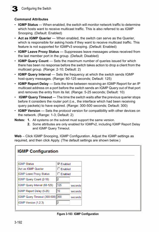
Configuring the Switch3
Command Attributes• IGMP Status — When enabled, the switch will monitor network traffic to determine which hosts want to receive multicast traffic. This is also referred to as IGMP Snooping. (Default: Enabled)
• Act as IGMP Querier — When enabled, the switch can serve as the Querier, which is responsible for asking hosts if they want to receive multicast traffic. This feature is not supported for IGMPv3 snooping. (Default: Enabled)
• IGMP Leave Proxy Status — Suppresses leave messages unless received from the last member port in the group. (Default: Disabled)
• IGMP Query Count — Sets the maximum number of queries issued for which there has been no response before the switch takes action to drop a client from the multicast group. (Range: 2-10; Default: 2)
• IGMP Query Interval — Sets the frequency at which the switch sends IGMP host-query messages. (Range: 60-125 seconds; Default: 125)
• IGMP Report Delay — Sets the time between receiving an IGMP Report for an IP multicast address on a port before the switch sends an IGMP Query out of that port and removes the entry from its list. (Range: 5-25 seconds; Default: 10)
• IGMP Query Timeout — The time the switch waits after the previous querier stops before it considers the router port (i.e., the interface which had been receiving query packets) to have expired. (Range: 300-500 seconds; Default: 300)
• IGMP Version — Sets the protocol version for compatibility with other devices on the network. (Range: 1-3; Default: 2)
Notes: 1. All systems on the subnet must support the same version. 2. Some attributes are only enabled for IGMPv2, including IGMP Report Delay
and IGMP Query Timeout.
Web – Click IGMP Snooping, IGMP Configuration. Adjust the IGMP settings as required, and then click Apply. (The default settings are shown below.)
Figure 3-103 IGMP Configuration
3-192
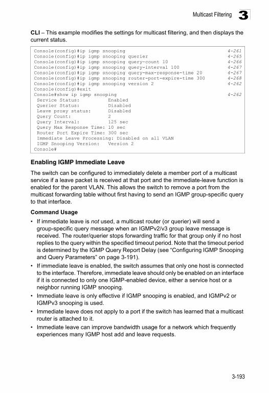
Multicast Filtering 3
CLI – This example modifies the settings for multicast filtering, and then displays the current status.Enabling IGMP Immediate Leave
The switch can be configured to immediately delete a member port of a multicast service if a leave packet is received at that port and the immediate-leave function is enabled for the parent VLAN. This allows the switch to remove a port from the multicast forwarding table without first having to send an IGMP group-specific query to that interface.
Command Usage
• If immediate leave is not used, a multicast router (or querier) will send a group-specific query message when an IGMPv2/v3 group leave message is received. The router/querier stops forwarding traffic for that group only if no host replies to the query within the specified timeout period. Note that the timeout period is determined by the IGMP Query Report Delay (see “Configuring IGMP Snooping and Query Parameters” on page 3-191).
• If immediate leave is enabled, the switch assumes that only one host is connected to the interface. Therefore, immediate leave should only be enabled on an interface if it is connected to only one IGMP-enabled device, either a service host or a neighbor running IGMP snooping.
• Immediate leave is only effective if IGMP snooping is enabled, and IGMPv2 or IGMPv3 snooping is used.
• Immediate leave does not apply to a port if the switch has learned that a multicast router is attached to it.
• Immediate leave can improve bandwidth usage for a network which frequently experiences many IGMP host add and leave requests.
Console(config)#ip igmp snooping 4-261Console(config)#ip igmp snooping querier 4-265Console(config)#ip igmp snooping query-count 10 4-266Console(config)#ip igmp snooping query-interval 100 4-267Console(config)#ip igmp snooping query-max-response-time 20 4-267Console(config)#ip igmp snooping router-port-expire-time 300 4-268Console(config)#ip igmp snooping version 2 4-262Console(config)#exitConsole#show ip igmp snooping 4-262 Service Status: Enabled Querier Status: Disabled Leave proxy status: Disabled Query Count: 2 Query Interval: 125 sec Query Max Response Time: 10 sec Router Port Expire Time: 300 sec Immediate Leave Processing: Disabled on all VLAN IGMP Snooping Version: Version 2Console#
3-193
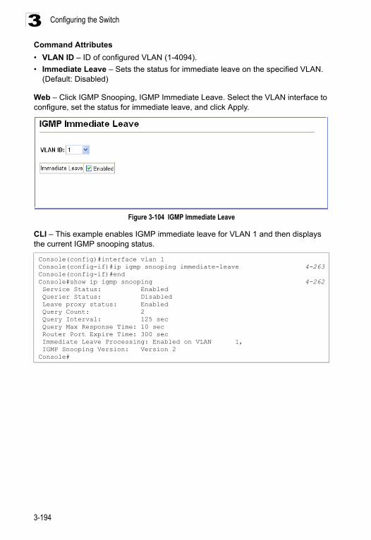
Configuring the Switch3
Command Attributes• VLAN ID – ID of configured VLAN (1-4094).
• Immediate Leave – Sets the status for immediate leave on the specified VLAN. (Default: Disabled)
Web – Click IGMP Snooping, IGMP Immediate Leave. Select the VLAN interface to configure, set the status for immediate leave, and click Apply.
Figure 3-104 IGMP Immediate Leave
CLI – This example enables IGMP immediate leave for VLAN 1 and then displays the current IGMP snooping status.
Console(config)#interface vlan 1Console(config-if)#ip igmp snooping immediate-leave 4-263Console(config-if)#endConsole#show ip igmp snooping 4-262 Service Status: Enabled Querier Status: Disabled Leave proxy status: Enabled Query Count: 2 Query Interval: 125 sec Query Max Response Time: 10 sec Router Port Expire Time: 300 sec Immediate Leave Processing: Enabled on VLAN 1, IGMP Snooping Version: Version 2Console#
3-194
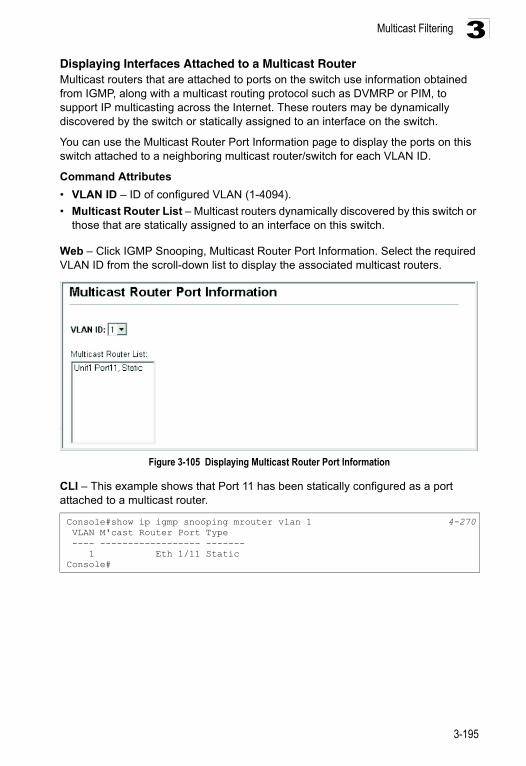
Multicast Filtering 3
Displaying Interfaces Attached to a Multicast RouterMulticast routers that are attached to ports on the switch use information obtained from IGMP, along with a multicast routing protocol such as DVMRP or PIM, to support IP multicasting across the Internet. These routers may be dynamically discovered by the switch or statically assigned to an interface on the switch.You can use the Multicast Router Port Information page to display the ports on this switch attached to a neighboring multicast router/switch for each VLAN ID.
Command Attributes
• VLAN ID – ID of configured VLAN (1-4094).
• Multicast Router List – Multicast routers dynamically discovered by this switch or those that are statically assigned to an interface on this switch.
Web – Click IGMP Snooping, Multicast Router Port Information. Select the required VLAN ID from the scroll-down list to display the associated multicast routers.
Figure 3-105 Displaying Multicast Router Port Information
CLI – This example shows that Port 11 has been statically configured as a port attached to a multicast router.
Console#show ip igmp snooping mrouter vlan 1 4-270 VLAN M'cast Router Port Type ---- ------------------ ------- 1 Eth 1/11 StaticConsole#
3-195
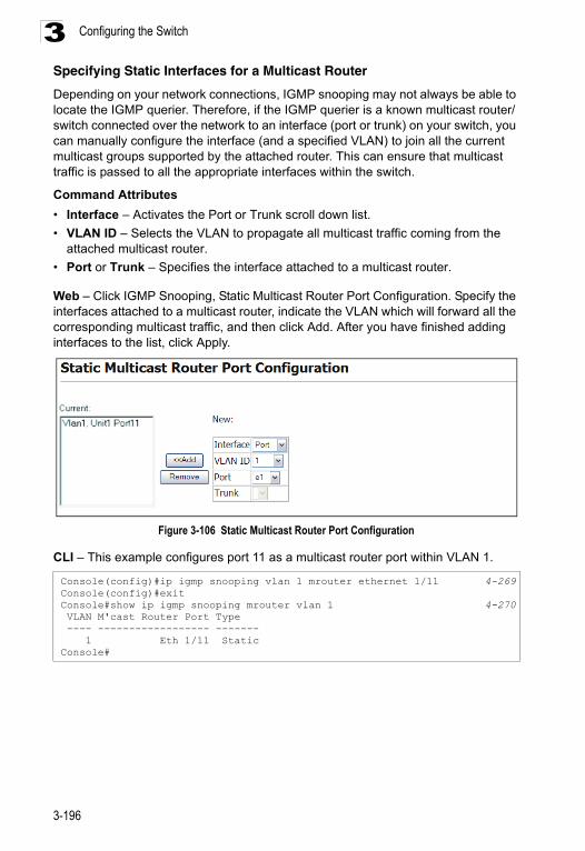
Configuring the Switch3
Specifying Static Interfaces for a Multicast RouterDepending on your network connections, IGMP snooping may not always be able to locate the IGMP querier. Therefore, if the IGMP querier is a known multicast router/ switch connected over the network to an interface (port or trunk) on your switch, you can manually configure the interface (and a specified VLAN) to join all the current multicast groups supported by the attached router. This can ensure that multicast traffic is passed to all the appropriate interfaces within the switch.
Command Attributes
• Interface – Activates the Port or Trunk scroll down list.
• VLAN ID – Selects the VLAN to propagate all multicast traffic coming from the attached multicast router.
• Port or Trunk – Specifies the interface attached to a multicast router.
Web – Click IGMP Snooping, Static Multicast Router Port Configuration. Specify the interfaces attached to a multicast router, indicate the VLAN which will forward all the corresponding multicast traffic, and then click Add. After you have finished adding interfaces to the list, click Apply.
Figure 3-106 Static Multicast Router Port Configuration
CLI – This example configures port 11 as a multicast router port within VLAN 1.
Console(config)#ip igmp snooping vlan 1 mrouter ethernet 1/11 4-269Console(config)#exitConsole#show ip igmp snooping mrouter vlan 1 4-270 VLAN M'cast Router Port Type ---- ------------------ ------- 1 Eth 1/11 StaticConsole#
3-196
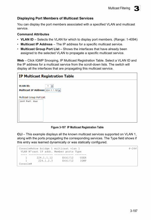
Multicast Filtering 3
Displaying Port Members of Multicast ServicesYou can display the port members associated with a specified VLAN and multicast service.
Command Attributes
• VLAN ID – Selects the VLAN for which to display port members. (Range: 1-4094)
• Multicast IP Address – The IP address for a specific multicast service.
• Multicast Group Port List – Shows the interfaces that have already been assigned to the selected VLAN to propagate a specific multicast service.
Web – Click IGMP Snooping, IP Multicast Registration Table. Select a VLAN ID and the IP address for a multicast service from the scroll-down lists. The switch will display all the interfaces that are propagating this multicast service.
Figure 3-107 IP Multicast Registration Table
CLI – This example displays all the known multicast services supported on VLAN 1, along with the ports propagating the corresponding services. The Type field shows if this entry was learned dynamically or was statically configured.
Console#show bridge 1 multicast vlan 1 4-264 VLAN M'cast IP addr. Member ports Type ---- --------------- ------------ ------- 1 224.1.1.12 Eth1/12 USER 1 224.1.2.3 Eth1/12 IGMPConsole#
3-197
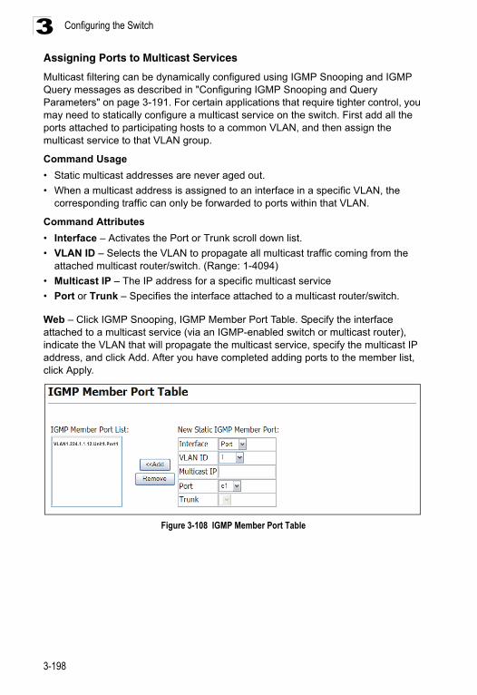
Configuring the Switch3
Assigning Ports to Multicast ServicesMulticast filtering can be dynamically configured using IGMP Snooping and IGMP Query messages as described in "Configuring IGMP Snooping and Query Parameters" on page 3-191. For certain applications that require tighter control, you may need to statically configure a multicast service on the switch. First add all the ports attached to participating hosts to a common VLAN, and then assign the multicast service to that VLAN group.
Command Usage
• Static multicast addresses are never aged out.
• When a multicast address is assigned to an interface in a specific VLAN, the corresponding traffic can only be forwarded to ports within that VLAN.
Command Attributes
• Interface – Activates the Port or Trunk scroll down list.
• VLAN ID – Selects the VLAN to propagate all multicast traffic coming from the attached multicast router/switch. (Range: 1-4094)
• Multicast IP – The IP address for a specific multicast service
• Port or Trunk – Specifies the interface attached to a multicast router/switch.
Web – Click IGMP Snooping, IGMP Member Port Table. Specify the interface attached to a multicast service (via an IGMP-enabled switch or multicast router), indicate the VLAN that will propagate the multicast service, specify the multicast IP address, and click Add. After you have completed adding ports to the member list, click Apply.
Figure 3-108 IGMP Member Port Table
3-198
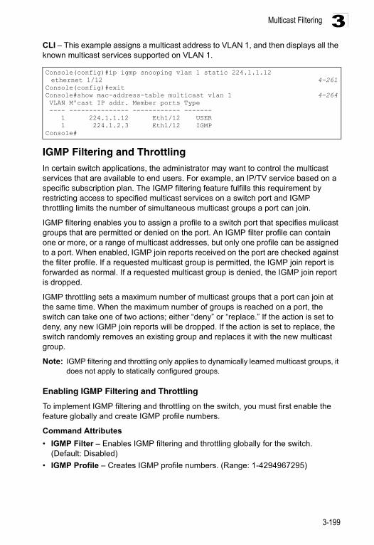
Multicast Filtering 3
CLI – This example assigns a multicast address to VLAN 1, and then displays all the known multicast services supported on VLAN 1.IGMP Filtering and ThrottlingIn certain switch applications, the administrator may want to control the multicast services that are available to end users. For example, an IP/TV service based on a specific subscription plan. The IGMP filtering feature fulfills this requirement by restricting access to specified multicast services on a switch port and IGMP throttling limits the number of simultaneous multicast groups a port can join.
IGMP filtering enables you to assign a profile to a switch port that specifies mulicast groups that are permitted or denied on the port. An IGMP filter profile can contain one or more, or a range of multicast addresses, but only one profile can be assigned to a port. When enabled, IGMP join reports received on the port are checked against the filter profile. If a requested multicast group is permitted, the IGMP join report is forwarded as normal. If a requested multicast group is denied, the IGMP join report is dropped.
IGMP throttling sets a maximum number of multicast groups that a port can join at the same time. When the maximum number of groups is reached on a port, the switch can take one of two actions; either “deny” or “replace.” If the action is set to deny, any new IGMP join reports will be dropped. If the action is set to replace, the switch randomly removes an existing group and replaces it with the new multicast group.
Note: IGMP filtering and throttling only applies to dynamically learned multicast groups, it does not apply to statically configured groups.
Enabling IGMP Filtering and Throttling
To implement IGMP filtering and throttling on the switch, you must first enable the feature globally and create IGMP profile numbers.
Command Attributes
• IGMP Filter – Enables IGMP filtering and throttling globally for the switch. (Default: Disabled)
• IGMP Profile – Creates IGMP profile numbers. (Range: 1-4294967295)
Console(config)#ip igmp snooping vlan 1 static 224.1.1.12 ethernet 1/12 4-261
Console(config)#exitConsole#show mac-address-table multicast vlan 1 4-264 VLAN M'cast IP addr. Member ports Type ---- --------------- ------------ ------- 1 224.1.1.12 Eth1/12 USER 1 224.1.2.3 Eth1/12 IGMPConsole#
3-199
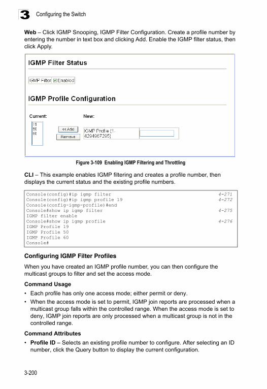
Configuring the Switch3
Web – Click IGMP Snooping, IGMP Filter Configuration. Create a profile number by entering the number in text box and clicking Add. Enable the IGMP filter status, then click Apply.Figure 3-109 Enabling IGMP Filtering and Throttling
CLI – This example enables IGMP filtering and creates a profile number, then displays the current status and the existing profile numbers.
Configuring IGMP Filter Profiles
When you have created an IGMP profile number, you can then configure the multicast groups to filter and set the access mode.
Command Usage
• Each profile has only one access mode; either permit or deny.
• When the access mode is set to permit, IGMP join reports are processed when a multicast group falls within the controlled range. When the access mode is set to deny, IGMP join reports are only processed when a multicast group is not in the controlled range.
Command Attributes
• Profile ID – Selects an existing profile number to configure. After selecting an ID number, click the Query button to display the current configuration.
Console(config)#ip igmp filter 4-271Console(config)#ip igmp profile 19 4-272Console(config-igmp-profile)#endConsole#show ip igmp filter 4-275IGMP filter enableConsole#show ip igmp profile 4-276IGMP Profile 19IGMP Profile 50IGMP Profile 60Console#
3-200
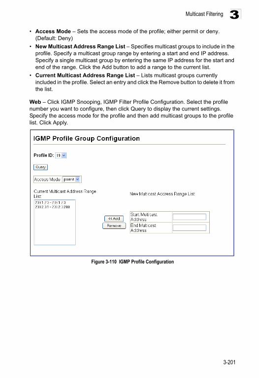
Multicast Filtering 3
• Access Mode – Sets the access mode of the profile; either permit or deny.(Default: Deny)
• New Multicast Address Range List – Specifies multicast groups to include in the profile. Specify a multicast group range by entering a start and end IP address. Specify a single multicast group by entering the same IP address for the start and end of the range. Click the Add button to add a range to the current list.
• Current Multicast Address Range List – Lists multicast groups currently included in the profile. Select an entry and click the Remove button to delete it from the list.
Web – Click IGMP Snooping, IGMP Filter Profile Configuration. Select the profile number you want to configure, then click Query to display the current settings. Specify the access mode for the profile and then add multicast groups to the profile list. Click Apply.
Figure 3-110 IGMP Profile Configuration
3-201
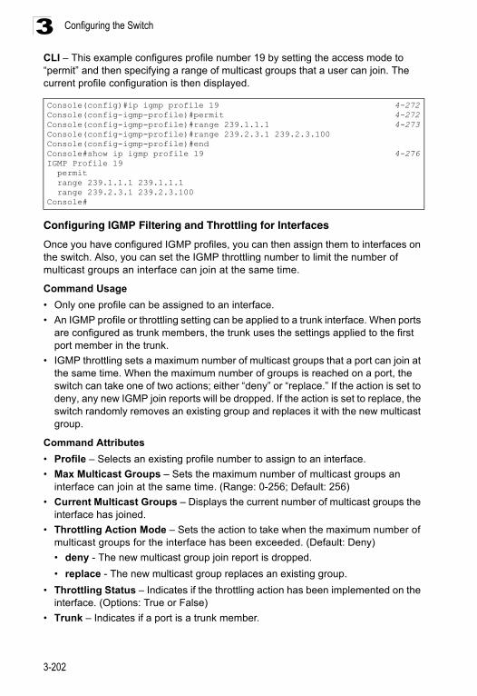
Configuring the Switch3
CLI – This example configures profile number 19 by setting the access mode to “permit” and then specifying a range of multicast groups that a user can join. The current profile configuration is then displayed.Configuring IGMP Filtering and Throttling for Interfaces
Once you have configured IGMP profiles, you can then assign them to interfaces on the switch. Also, you can set the IGMP throttling number to limit the number of multicast groups an interface can join at the same time.
Command Usage
• Only one profile can be assigned to an interface.
• An IGMP profile or throttling setting can be applied to a trunk interface. When ports are configured as trunk members, the trunk uses the settings applied to the first port member in the trunk.
• IGMP throttling sets a maximum number of multicast groups that a port can join at the same time. When the maximum number of groups is reached on a port, the switch can take one of two actions; either “deny” or “replace.” If the action is set to deny, any new IGMP join reports will be dropped. If the action is set to replace, the switch randomly removes an existing group and replaces it with the new multicast group.
Command Attributes
• Profile – Selects an existing profile number to assign to an interface.
• Max Multicast Groups – Sets the maximum number of multicast groups an interface can join at the same time. (Range: 0-256; Default: 256)
• Current Multicast Groups – Displays the current number of multicast groups the interface has joined.
• Throttling Action Mode – Sets the action to take when the maximum number of multicast groups for the interface has been exceeded. (Default: Deny)
• deny - The new multicast group join report is dropped.
• replace - The new multicast group replaces an existing group.
• Throttling Status – Indicates if the throttling action has been implemented on the interface. (Options: True or False)
• Trunk – Indicates if a port is a trunk member.
Console(config)#ip igmp profile 19 4-272Console(config-igmp-profile)#permit 4-272Console(config-igmp-profile)#range 239.1.1.1 4-273Console(config-igmp-profile)#range 239.2.3.1 239.2.3.100Console(config-igmp-profile)#endConsole#show ip igmp profile 19 4-276IGMP Profile 19 permit range 239.1.1.1 239.1.1.1 range 239.2.3.1 239.2.3.100Console#
3-202
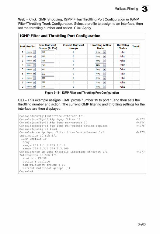
Multicast Filtering 3
Web – Click IGMP Snooping, IGMP Filter/Throttling Port Configuration or IGMP Filter/Throttling Trunk Configuration. Select a profile to assign to an interface, then set the throttling number and action. Click Apply.Figure 3-111 IGMP Filter and Throttling Port Configuration
CLI – This example assigns IGMP profile number 19 to port 1, and then sets the throttling number and action. The current IGMP filtering and throttling settings for the interface are then displayed.
Console(config)#interface ethernet 1/1Console(config-if)#ip igmp filter 19 4-273Console(config-if)#ip igmp max-groups 10 4-274Console(config-if)#ip igmp max-groups action replace 4-275Console(config-if)#endConsole#show ip igmp filter interface ethernet 1/1 4-275Information of Eth 1/1 IGMP Profile 19 deny range 239.1.1.1 239.1.1.1 range 239.2.3.1 239.2.3.100Console#show ip igmp throttle interface ethernet 1/1 4-277Information of Eth 1/1 status : FALSE action : replace max multicast groups : 10 current multicast groups : 1Console#
3-203
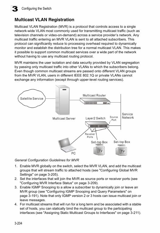
Configuring the Switch3
Multicast VLAN Registration Multicast VLAN Registration (MVR) is a protocol that controls access to a single network-wide VLAN most commonly used for transmitting multicast traffic (such as television channels or video-on-demand) across a service provider’s network. Any multicast traffic entering an MVR VLAN is sent to all attached subscribers. This protocol can significantly reduce to processing overhead required to dynamically monitor and establish the distribution tree for a normal multicast VLAN. This makes it possible to support common multicast services over a wide part of the network without having to use any multicast routing protocol.MVR maintains the user isolation and data security provided by VLAN segregation by passing only multicast traffic into other VLANs to which the subscribers belong. Even though common multicast streams are passed onto different VLAN groups from the MVR VLAN, users in different IEEE 802.1Q or private VLANs cannot exchange any information (except through upper-level routing services).
General Configuration Guidelines for MVR
1. Enable MVR globally on the switch, select the MVR VLAN, and add the multicast groups that will stream traffic to attached hosts (see "Configuring Global MVR Settings" on page 3-205).
2. Set the interfaces that will join the MVR as source ports or receiver ports (see "Configuring MVR Interface Status" on page 3-209).
3. Enable IGMP Snooping to a allow a subscriber to dynamically join or leave an MVR group (see "Configuring IGMP Snooping and Query Parameters" on page 3-191). Note that only IGMP version 2 or 3 hosts can issue multicast join or leave messages.
4. For multicast streams that will run for a long term and be associated with a stable set of hosts, you can statically bind the multicast group to the participating interfaces (see "Assigning Static Multicast Groups to Interfaces" on page 3-211).
3-204
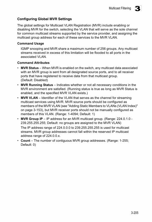
Multicast Filtering 3
Configuring Global MVR SettingsThe global settings for Multicast VLAN Registration (MVR) include enabling or disabling MVR for the switch, selecting the VLAN that will serve as the sole channel for common multicast streams supported by the service provider, and assigning the multicast group address for each of these services to the MVR VLAN.
Command Usage
IGMP snooping and MVR share a maximum number of 256 groups. Any multicast streams received in excess of this limitation will be flooded to all ports in the associated VLAN.
Command Attributes
• MVR Status – When MVR is enabled on the switch, any multicast data associated with an MVR group is sent from all designated source ports, and to all receiver ports that have registered to receive data from that multicast group. (Default: Disabled)
• MVR Running Status – Indicates whether or not all necessary conditions in the MVR environment are satisfied. (Running status is true as long as MVR Status is enabled, and the specified MVR VLAN exists.)
• MVR VLAN – Identifier of the VLAN that serves as the channel for streaming multicast services using MVR. MVR source ports should be configured as members of the MVR VLAN (see "Adding Static Members to VLANs (VLAN Index)" on page 3-153), but MVR receiver ports should not be manually configured as members of this VLAN. (Range: 1-4094; Default: 1)
• MVR Group IP – IP address for an MVR multicast group. (Range: 224.0.1.0 - 239.255.255.255; Default: no groups are assigned to the MVR VLAN)
The IP address range of 224.0.0.0 to 239.255.255.255 is used for multicast streams. MVR group addresses cannot fall within the reserved IP multicast address range of 224.0.0.x.
• Count – The number of contiguous MVR group addresses. (Range: 1-255; Default: 0)
3-205
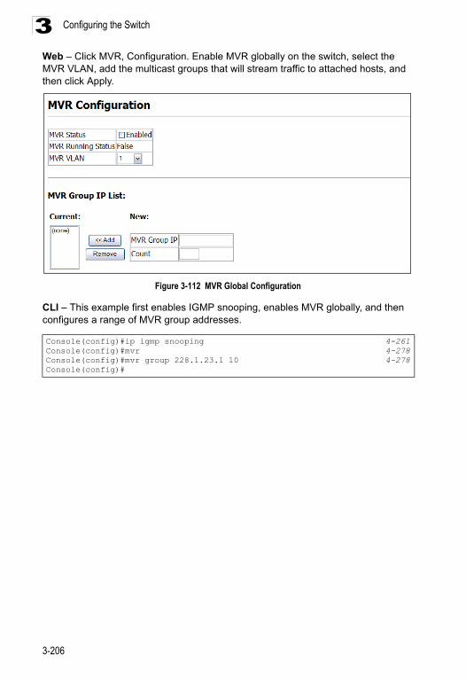
Configuring the Switch3
Web – Click MVR, Configuration. Enable MVR globally on the switch, select the MVR VLAN, add the multicast groups that will stream traffic to attached hosts, and then click Apply.Figure 3-112 MVR Global Configuration
CLI – This example first enables IGMP snooping, enables MVR globally, and then configures a range of MVR group addresses.
Console(config)#ip igmp snooping 4-261Console(config)#mvr 4-278Console(config)#mvr group 228.1.23.1 10 4-278Console(config)#
3-206
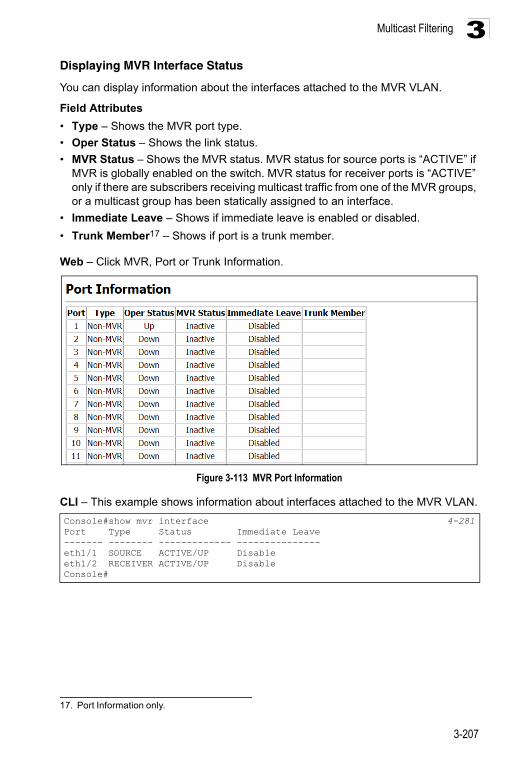
Multicast Filtering 3
Displaying MVR Interface StatusYou can display information about the interfaces attached to the MVR VLAN.
Field Attributes
• Type – Shows the MVR port type.
• Oper Status – Shows the link status.
• MVR Status – Shows the MVR status. MVR status for source ports is “ACTIVE” if MVR is globally enabled on the switch. MVR status for receiver ports is “ACTIVE” only if there are subscribers receiving multicast traffic from one of the MVR groups, or a multicast group has been statically assigned to an interface.
• Immediate Leave – Shows if immediate leave is enabled or disabled.
• Trunk Member17 – Shows if port is a trunk member.
Web – Click MVR, Port or Trunk Information.
Figure 3-113 MVR Port Information
CLI – This example shows information about interfaces attached to the MVR VLAN.
17. Port Information only.
Console#show mvr interface 4-281Port Type Status Immediate Leave------- -------- ------------- ---------------eth1/1 SOURCE ACTIVE/UP Disableeth1/2 RECEIVER ACTIVE/UP DisableConsole#
3-207
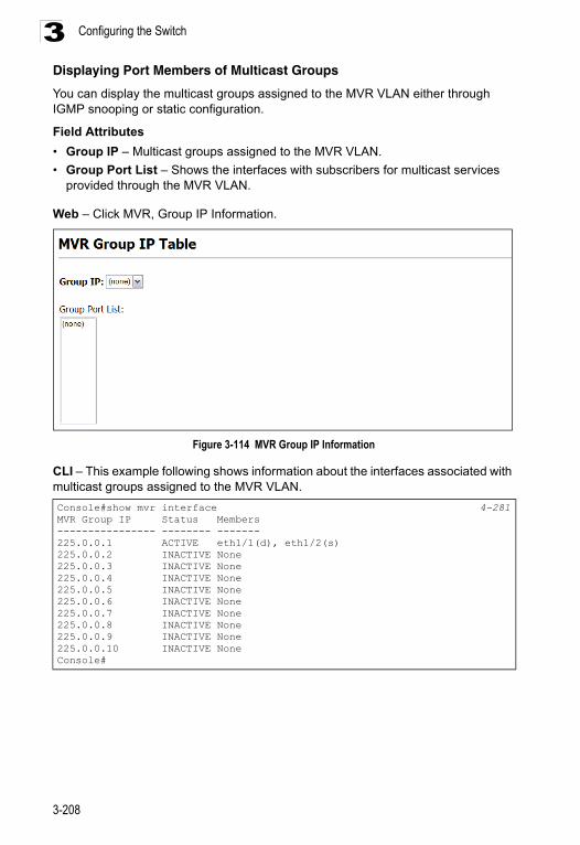
Configuring the Switch3
Displaying Port Members of Multicast GroupsYou can display the multicast groups assigned to the MVR VLAN either through IGMP snooping or static configuration.
Field Attributes
• Group IP – Multicast groups assigned to the MVR VLAN.
• Group Port List – Shows the interfaces with subscribers for multicast services provided through the MVR VLAN.
Web – Click MVR, Group IP Information.
Figure 3-114 MVR Group IP Information
CLI – This example following shows information about the interfaces associated with multicast groups assigned to the MVR VLAN.
Console#show mvr interface 4-281MVR Group IP Status Members---------------- -------- -------225.0.0.1 ACTIVE eth1/1(d), eth1/2(s)225.0.0.2 INACTIVE None225.0.0.3 INACTIVE None225.0.0.4 INACTIVE None225.0.0.5 INACTIVE None225.0.0.6 INACTIVE None225.0.0.7 INACTIVE None225.0.0.8 INACTIVE None225.0.0.9 INACTIVE None225.0.0.10 INACTIVE NoneConsole#
3-208
Multicast Filtering 3
Configuring MVR Interface StatusEach interface that participates in the MVR VLAN must be configured as an MVR source port or receiver port. If only one subscriber attached to an interface is receiving multicast services, you can enable the immediate leave function.
Command Usage
• A port which is not configured as an MVR receiver or source port can use IGMP snooping to join or leave multicast groups using the standard rules for multicast filtering.
• Receiver ports can belong to different VLANs, but should not be configured as a member of the MVR VLAN. IGMP snooping can be used to allow a receiver port to dynamically join or leave multicast groups within an MVR VLAN. Multicast groups can also be statically assigned to a receiver port (see "Assigning Static Multicast Groups to Interfaces" on page 3-211). However, if a receiver port is statically configured as a member of an MVR VLAN, its MVR status will be inactive. Also, note that VLAN membership for MVR receiver ports cannot be set to trunk mode (see "Configuring VLAN Behavior for Interfaces" on page 3-156).
• One or more interfaces may be configured as MVR source ports. A source port is able to both receive and send data for multicast groups which it has joined through IGMP snooping or which have been statically assigned (see "Assigning Static Multicast Groups to Interfaces" on page 3-211).
• Immediate leave applies only to receiver ports. When enabled, the receiver port is immediately removed from the multicast group identified in the leave message. When immediate leave is disabled, the switch follows the standard rules by sending a group-specific query to the receiver port and waiting for a response to determine if there are any remaining subscribers for that multicast group before removing the port from the group list.
- Using immediate leave can speed up leave latency, but should only be enabled on a port attached to one multicast subscriber to avoid disrupting services to other group members attached to the same interface.
- Immediate leave does not apply to multicast groups which have been statically assigned to a port.
Command Attributes
• MVR Type – The following interface types are supported:
- Source – An uplink port that can send and receive multicast data for the groups assigned to the MVR VLAN. Note that the source port must be manually configured as a member of the MVR VLAN (see "Adding Static Members to VLANs (VLAN Index)" on page 3-153).
- Receiver – A subscriber port that can receive multicast data sent through the MVR VLAN. Any port configured as an receiver port will be dynamically added to the MVR VLAN when it forwards an IGMP report or join message from an attached host requesting any of the designated multicast services supported by the MVR VLAN.
3-209
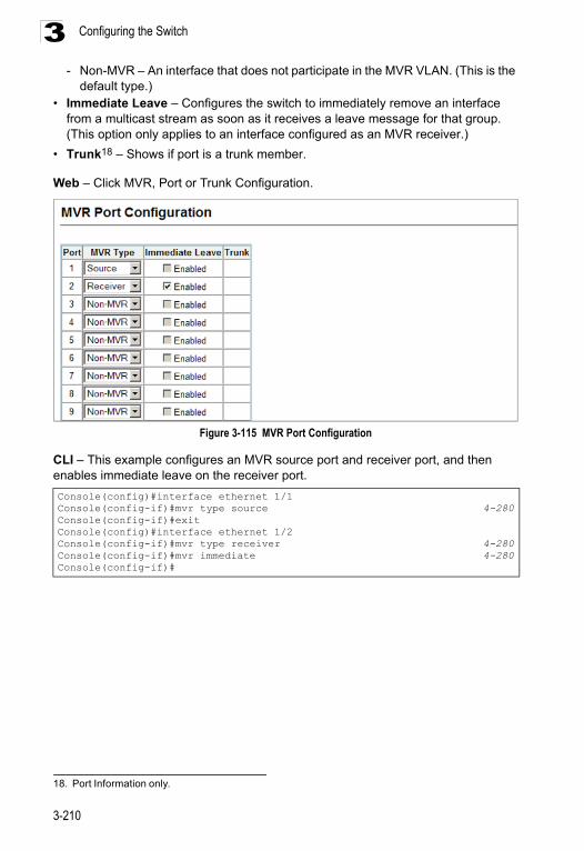
Configuring the Switch3
- Non-MVR – An interface that does not participate in the MVR VLAN. (This is thedefault type.)• Immediate Leave – Configures the switch to immediately remove an interface
from a multicast stream as soon as it receives a leave message for that group. (This option only applies to an interface configured as an MVR receiver.)
• Trunk18 – Shows if port is a trunk member.
Web – Click MVR, Port or Trunk Configuration.
Figure 3-115 MVR Port Configuration
CLI – This example configures an MVR source port and receiver port, and then enables immediate leave on the receiver port.
18. Port Information only.
Console(config)#interface ethernet 1/1 Console(config-if)#mvr type source 4-280Console(config-if)#exitConsole(config)#interface ethernet 1/2Console(config-if)#mvr type receiver 4-280Console(config-if)#mvr immediate 4-280Console(config-if)#
3-210
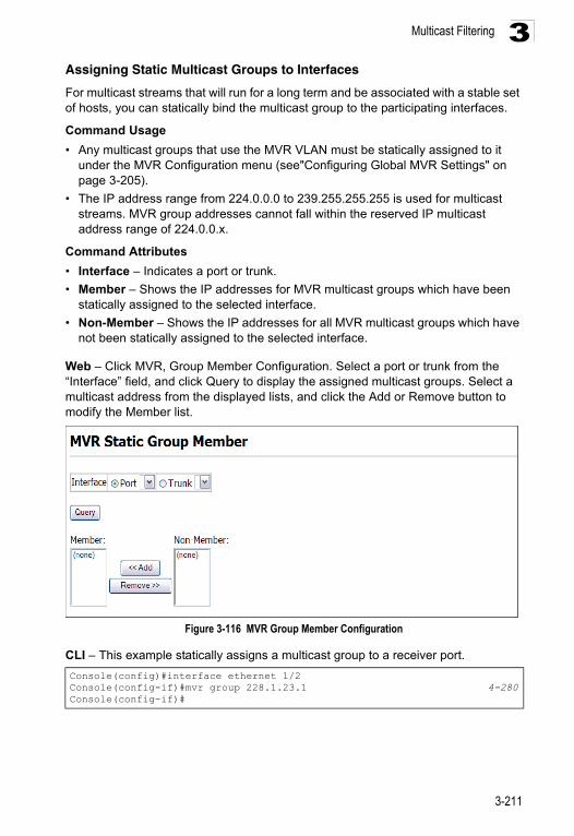
Multicast Filtering 3
Assigning Static Multicast Groups to InterfacesFor multicast streams that will run for a long term and be associated with a stable set of hosts, you can statically bind the multicast group to the participating interfaces.
Command Usage
• Any multicast groups that use the MVR VLAN must be statically assigned to it under the MVR Configuration menu (see"Configuring Global MVR Settings" on page 3-205).
• The IP address range from 224.0.0.0 to 239.255.255.255 is used for multicast streams. MVR group addresses cannot fall within the reserved IP multicast address range of 224.0.0.x.
Command Attributes
• Interface – Indicates a port or trunk.
• Member – Shows the IP addresses for MVR multicast groups which have been statically assigned to the selected interface.
• Non-Member – Shows the IP addresses for all MVR multicast groups which have not been statically assigned to the selected interface.
Web – Click MVR, Group Member Configuration. Select a port or trunk from the “Interface” field, and click Query to display the assigned multicast groups. Select a multicast address from the displayed lists, and click the Add or Remove button to modify the Member list.
Figure 3-116 MVR Group Member Configuration
CLI – This example statically assigns a multicast group to a receiver port.
Console(config)#interface ethernet 1/2 Console(config-if)#mvr group 228.1.23.1 4-280Console(config-if)#
3-211
Configuring the Switch3
Configuring Domain Name Service The Domain Naming System (DNS) service on this switch allows host names to be mapped to IP addresses using static table entries or by redirection to other name servers on the network. When a client device designates this switch as a DNS server, the client will attempt to resolve host names into IP addresses by forwarding DNS queries to the switch, and waiting for a response.You can manually configure entries in the DNS table used for mapping domain names to IP addresses, configure default domain names, or specify one or more name servers to use for domain name to address translation.
Configuring General DNS Service Parameters
Command Usage
• To enable DNS service on this switch, first configure one or more name servers, and then enable domain lookup status.
• To append domain names to incomplete host names received from a DNS client (i.e., not formatted with dotted notation), you can specify a default domain name or a list of domain names to be tried in sequential order.
• If there is no domain list, the default domain name is used. If there is a domain list, the default domain name is not used.
• When an incomplete host name is received by the DNS service on this switch and a domain name list has been specified, the switch will work through the domain list, appending each domain name in the list to the host name, and checking with the specified name servers for a match.
• When more than one name server is specified, the servers are queried in the specified sequence until a response is received, or the end of the list is reached with no response.
• Note that if all name servers are deleted, DNS will automatically be disabled.
Command Attributes
• Domain Lookup Status – Enables DNS host name-to-address translation.
• Default Domain Name19 – Defines the default domain name appended to incomplete host names. (Range: 1-64 alphanumeric characters)
• Domain Name List – Defines a list of domain names that can be appended to incomplete host names. (Range: 1-64 alphanumeric characters. 1-5 names)
• Name Server List – Specifies the address of one or more domain name servers to use for name-to-address resolution. (Range: 1-6 IP addresses)
19. Do not include the initial dot that separates the host name from the domain name.
3-212
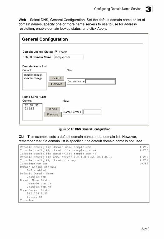
Configuring Domain Name Service 3
Web – Select DNS, General Configuration. Set the default domain name or list of domain names, specify one or more name servers to use to use for address resolution, enable domain lookup status, and click Apply.Figure 3-117 DNS General Configuration
CLI - This example sets a default domain name and a domain list. However, remember that if a domain list is specified, the default domain name is not used.
Console(config)#ip domain-name sample.com 4-285Console(config)#ip domain-list sample.com.uk 4-286Console(config)#ip domain-list sample.com.jpConsole(config)#ip name-server 192.168.1.55 10.1.0.55 4-287Console(config)#ip domain-lookup 4-288Console#show dns 4-289Domain Lookup Status: DNS enabledDefault Domain Name: .sample.comDomain Name List: .sample.com.uk .sample.com.jpName Server List: 192.168.1.55 10.1.0.55Console#
3-213
Configuring the Switch3
Configuring Static DNS Host to Address EntriesYou can manually configure static entries in the DNS table that are used to map domain names to IP addresses.Command Usage
• Static entries may be used for local devices connected directly to the attached network, or for commonly used resources located elsewhere on the network.
• Servers or other network devices may support one or more connections via multiple IP addresses. If more than one IP address is associated with a host name in the static table or via information returned from a name server, a DNS client can try each address in succession, until it establishes a connection with the target device.
Field Attributes
• Host Name – Name of a host device that is mapped to one or more IP addresses. (Range: 1-64 characters)
• IP Address – Internet address(es) associated with a host name. (Range: 1-8 addresses)
3-214
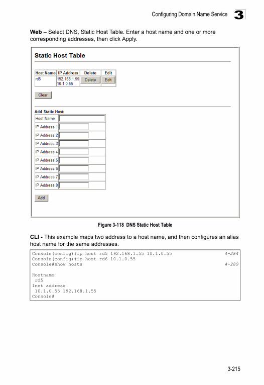
Configuring Domain Name Service 3
Web – Select DNS, Static Host Table. Enter a host name and one or more corresponding addresses, then click Apply.Figure 3-118 DNS Static Host Table
CLI - This example maps two address to a host name, and then configures an alias host name for the same addresses.
Console(config)#ip host rd5 192.168.1.55 10.1.0.55 4-284Console(config)#ip host rd6 10.1.0.55Console#show hosts 4-289
Hostname rd5Inet address 10.1.0.55 192.168.1.55Console#
3-215
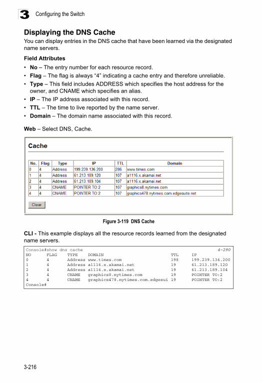
Configuring the Switch3
Displaying the DNS CacheYou can display entries in the DNS cache that have been learned via the designated name servers.Field Attributes
• No – The entry number for each resource record.
• Flag – The flag is always “4” indicating a cache entry and therefore unreliable.
• Type – This field includes ADDRESS which specifies the host address for the owner, and CNAME which specifies an alias.
• IP – The IP address associated with this record.
• TTL – The time to live reported by the name server.
• Domain – The domain name associated with this record.
Web – Select DNS, Cache.
Figure 3-119 DNS Cache
CLI - This example displays all the resource records learned from the designated name servers.
Console#show dns cache 4-290NO FLAG TYPE DOMAIN TTL IP0 4 Address www.times.com 198 199.239.136.2001 4 Address a1116.x.akamai.net 19 61.213.189.1202 4 Address a1116.x.akamai.net 19 61.213.189.1043 4 CNAME graphics8.nytimes.com 19 POINTER TO:24 4 CNAME graphics478.nytimes.com.edgesui 19 POINTER TO:2Console#
3-216
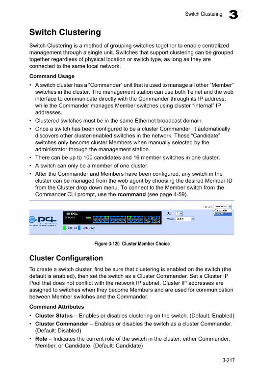
Switch Clustering 3
Switch ClusteringSwitch Clustering is a method of grouping switches together to enable centralized management through a single unit. Switches that support clustering can be grouped together regardless of physical location or switch type, as long as they are connected to the same local network.Command Usage
• A switch cluster has a “Commander” unit that is used to manage all other “Member” switches in the cluster. The management station can use both Telnet and the web interface to communicate directly with the Commander through its IP address, while the Commander manages Member switches using cluster “internal” IP addresses.
• Clustered switches must be in the same Ethernet broadcast domain.
• Once a switch has been configured to be a cluster Commander, it automatically discovers other cluster-enabled switches in the network. These “Candidate” switches only become cluster Members when manually selected by the administrator through the management station.
• There can be up to 100 candidates and 16 member switches in one cluster.
• A switch can only be a member of one cluster.
• After the Commander and Members have been configured, any switch in the cluster can be managed from the web agent by choosing the desired Member ID from the Cluster drop down menu. To connect to the Member switch from the Commander CLI prompt, use the rcommand (see page 4-59).
Figure 3-120 Cluster Member Choice
Cluster ConfigurationTo create a switch cluster, first be sure that clustering is enabled on the switch (the default is enabled), then set the switch as a Cluster Commander. Set a Cluster IP Pool that does not conflict with the network IP subnet. Cluster IP addresses are assigned to switches when they become Members and are used for communication between Member switches and the Commander.
Command Attributes
• Cluster Status – Enables or disables clustering on the switch. (Default: Enabled)
• Cluster Commander – Enables or disables the switch as a cluster Commander. (Default: Disabled)
• Role – Indicates the current role of the switch in the cluster; either Commander, Member, or Candidate. (Default: Candidate)
3-217
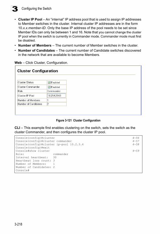
Configuring the Switch3
• Cluster IP Pool – An “internal” IP address pool that is used to assign IP addressesto Member switches in the cluster. Internal cluster IP addresses are in the form 10.x.x.member-ID. Only the base IP address of the pool needs to be set since Member IDs can only be between 1 and 16. Note that you cannot change the cluster IP pool when the switch is currently in Commander mode. Commander mode must first be disabled.
• Number of Members – The current number of Member switches in the cluster.
• Number of Candidates – The current number of Candidate switches discovered in the network that are available to become Members.
Web – Click Cluster, Configuration.
Figure 3-121 Cluster Configuration
CLI – This example first enables clustering on the switch, sets the switch as the cluster Commander, and then configures the cluster IP pool.
Console(config)#cluster 4-56Console(config)#cluster commander 4-57Console(config)#cluster ip-pool 10.2.3.4 4-58Console(config)#exitConsole#show cluster 4-59Role: commanderInterval heartbeat: 30Heartbeat loss count: 3Number of Members: 1Number of Candidates: 2Console#
3-218
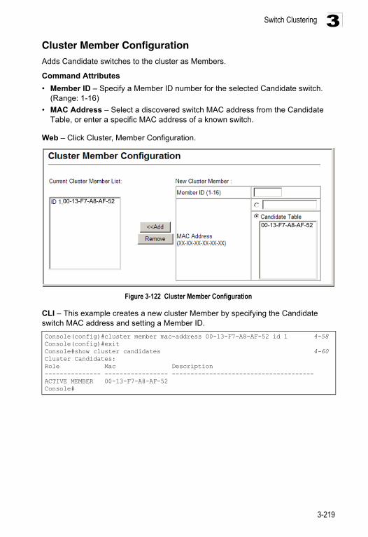
Switch Clustering 3
Cluster Member ConfigurationAdds Candidate switches to the cluster as Members.Command Attributes
• Member ID – Specify a Member ID number for the selected Candidate switch. (Range: 1-16)
• MAC Address – Select a discovered switch MAC address from the Candidate Table, or enter a specific MAC address of a known switch.
Web – Click Cluster, Member Configuration.
Figure 3-122 Cluster Member Configuration
CLI – This example creates a new cluster Member by specifying the Candidate switch MAC address and setting a Member ID.
Console(config)#cluster member mac-address 00-13-F7-A8-AF-52 id 1 4-58Console(config)#exitConsole#show cluster candidates 4-60Cluster Candidates:Role Mac Description--------------- ----------------- --------------------------------------ACTIVE MEMBER 00-13-F7-A8-AF-52 Console#
00-13-F7-A8-AF-52
00-13-F7-A8-AF-52
3-219
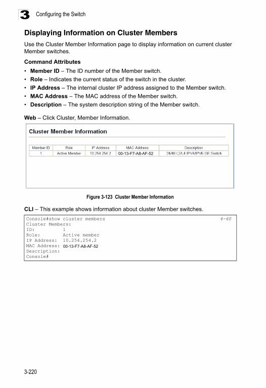
Configuring the Switch3
Displaying Information on Cluster MembersUse the Cluster Member Information page to display information on current cluster Member switches.Command Attributes
• Member ID – The ID number of the Member switch.
• Role – Indicates the current status of the switch in the cluster.
• IP Address – The internal cluster IP address assigned to the Member switch.
• MAC Address – The MAC address of the Member switch.
• Description – The system description string of the Member switch.
Web – Click Cluster, Member Information.
Figure 3-123 Cluster Member Information
CLI – This example shows information about cluster Member switches.
Console#show cluster members 4-60Cluster Members:ID: 1Role: Active memberIP Address: 10.254.254.2MAC Address: 00-30-fc-12-34-56Description: Console#
00-13-F7-A8-AF-52
00-13-F7-A8-AF-52
3-220
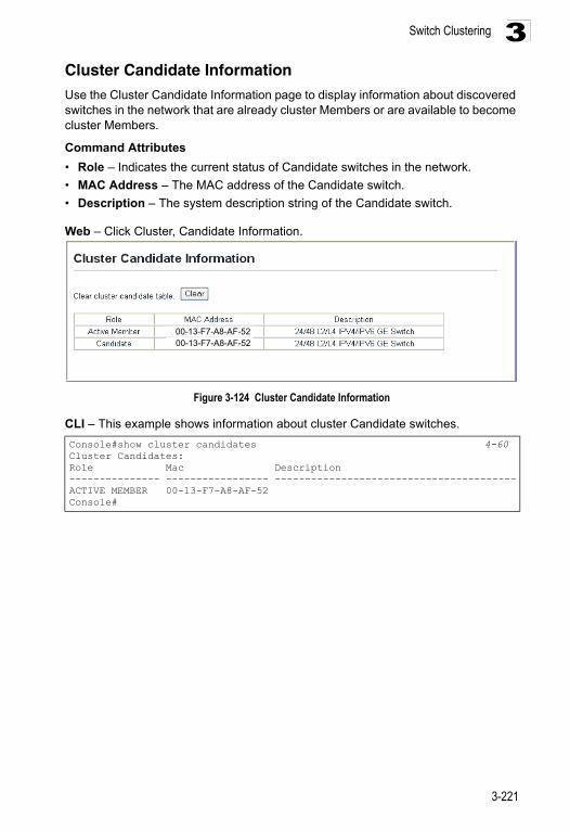
Switch Clustering 3
Cluster Candidate InformationUse the Cluster Candidate Information page to display information about discovered switches in the network that are already cluster Members or are available to become cluster Members.Command Attributes
• Role – Indicates the current status of Candidate switches in the network.
• MAC Address – The MAC address of the Candidate switch.
• Description – The system description string of the Candidate switch.
Web – Click Cluster, Candidate Information.
Figure 3-124 Cluster Candidate Information
CLI – This example shows information about cluster Candidate switches.
Console#show cluster candidates 4-60Cluster Candidates:Role Mac Description--------------- ----------------- ----------------------------------------ACTIVE MEMBER 00-13-F7-A8-AF-52Console#
00-13-F7-A8-AF-5200-13-F7-A8-AF-52
3-221

Configuring the Switch3
3-222
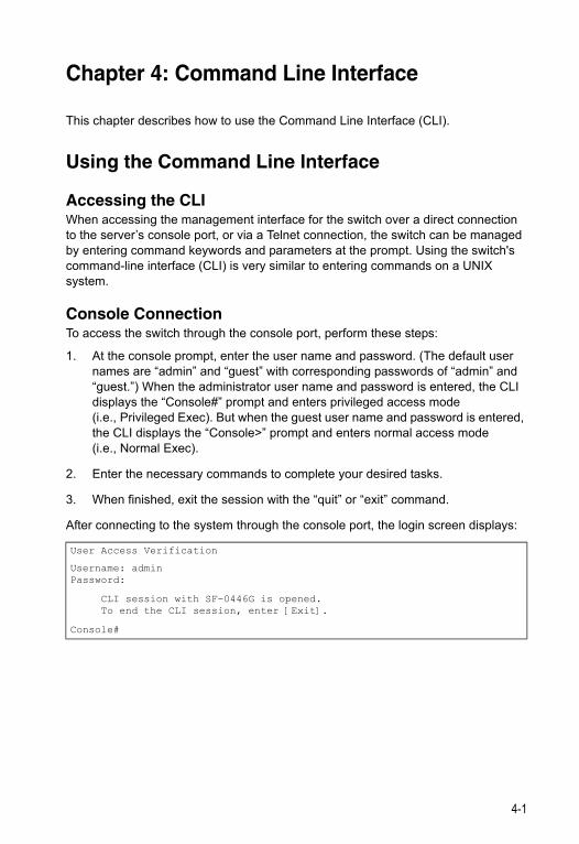
Chapter 4: Command Line Interface
This chapter describes how to use the Command Line Interface (CLI).
Using the Command Line Interface
Accessing the CLIWhen accessing the management interface for the switch over a direct connection to the server’s console port, or via a Telnet connection, the switch can be managed by entering command keywords and parameters at the prompt. Using the switch's command-line interface (CLI) is very similar to entering commands on a UNIX system.
Console ConnectionTo access the switch through the console port, perform these steps:
1. At the console prompt, enter the user name and password. (The default user names are “admin” and “guest” with corresponding passwords of “admin” and “guest.”) When the administrator user name and password is entered, the CLI displays the “Console#” prompt and enters privileged access mode (i.e., Privileged Exec). But when the guest user name and password is entered, the CLI displays the “Console>” prompt and enters normal access mode (i.e., Normal Exec).
2. Enter the necessary commands to complete your desired tasks.
3. When finished, exit the session with the “quit” or “exit” command.
After connecting to the system through the console port, the login screen displays:
User Access Verification
Username: adminPassword:
CLI session with SF-0446G is opened. To end the CLI session, enter [Exit].
Console#
4-1
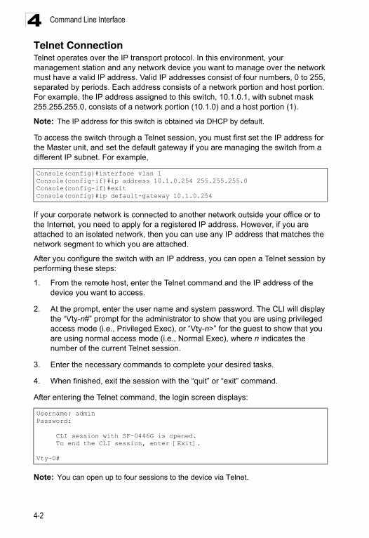
Command Line Interface4
Telnet ConnectionTelnet operates over the IP transport protocol. In this environment, your management station and any network device you want to manage over the network must have a valid IP address. Valid IP addresses consist of four numbers, 0 to 255, separated by periods. Each address consists of a network portion and host portion. For example, the IP address assigned to this switch, 10.1.0.1, with subnet mask 255.255.255.0, consists of a network portion (10.1.0) and a host portion (1).Note: The IP address for this switch is obtained via DHCP by default.
To access the switch through a Telnet session, you must first set the IP address for the Master unit, and set the default gateway if you are managing the switch from a different IP subnet. For example,
If your corporate network is connected to another network outside your office or to the Internet, you need to apply for a registered IP address. However, if you are attached to an isolated network, then you can use any IP address that matches the network segment to which you are attached.
After you configure the switch with an IP address, you can open a Telnet session by performing these steps:
1. From the remote host, enter the Telnet command and the IP address of the device you want to access.
2. At the prompt, enter the user name and system password. The CLI will display the “Vty-n#” prompt for the administrator to show that you are using privileged access mode (i.e., Privileged Exec), or “Vty-n>” for the guest to show that you are using normal access mode (i.e., Normal Exec), where n indicates the number of the current Telnet session.
3. Enter the necessary commands to complete your desired tasks.
4. When finished, exit the session with the “quit” or “exit” command.
After entering the Telnet command, the login screen displays:
Note: You can open up to four sessions to the device via Telnet.
Console(config)#interface vlan 1Console(config-if)#ip address 10.1.0.254 255.255.255.0Console(config-if)#exitConsole(config)#ip default-gateway 10.1.0.254
Username: adminPassword:
CLI session with SF-0446G is opened. To end the CLI session, enter [Exit].
Vty-0#
4-2
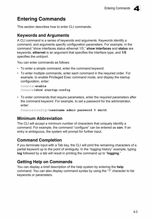
Entering Commands 4
Entering CommandsThis section describes how to enter CLI commands.Keywords and ArgumentsA CLI command is a series of keywords and arguments. Keywords identify a command, and arguments specify configuration parameters. For example, in the command “show interfaces status ethernet 1/5,” show interfaces and status are keywords, ethernet is an argument that specifies the interface type, and 1/5 specifies the unit/port.
You can enter commands as follows:
• To enter a simple command, enter the command keyword.
• To enter multiple commands, enter each command in the required order. For example, to enable Privileged Exec command mode, and display the startup configuration, enter:
Console>enableConsole#show startup-config
• To enter commands that require parameters, enter the required parameters after the command keyword. For example, to set a password for the administrator, enter:
Console(config)#username admin password 0 smith
Minimum AbbreviationThe CLI will accept a minimum number of characters that uniquely identify a command. For example, the command “configure” can be entered as con. If an entry is ambiguous, the system will prompt for further input.
Command CompletionIf you terminate input with a Tab key, the CLI will print the remaining characters of a partial keyword up to the point of ambiguity. In the “logging history” example, typing log followed by a tab will result in printing the command up to “logging.”
Getting Help on CommandsYou can display a brief description of the help system by entering the help command. You can also display command syntax by using the “?” character to list keywords or parameters.
4-3
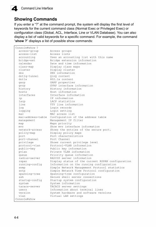
Command Line Interface4
Showing CommandsIf you enter a “?” at the command prompt, the system will display the first level of keywords for the current command class (Normal Exec or Privileged Exec) or configuration class (Global, ACL, Interface, Line or VLAN Database). You can also display a list of valid keywords for a specific command. For example, the command “show ?” displays a list of possible show commands:Console#show ? access-group Access groups access-list Access lists accounting Uses an accounting list with this name bridge-ext Bridge extension information calendar Date and time information class-map Display class maps cluster Display cluster dns DNS information dot1q-tunnel QinQ content dot1x 802.1x content garp GARP properties gvrp GVRP interface information history History information hosts Host information interfaces Interface information ip IP information lacp LACP statistics line TTY line information log Login records logging Login setting mac MAC access list mac-address-table Configuration of the address table management Management IP filter map Maps priority mvr Show mvr interface information network-access Shows the entries of the secure port. policy-map Display policy maps port Port characteristics port-channel Port Channel privilege Shows current privilege level protocol-vlan Protocol-VLAN information public-key Public key information pvlan Private VLAN information queue Priority queue information radius-server RADIUS server information rspan Display status of the current RSPAN configuration running-config Information on the running configuration snmp Simple Network Management Protocol statistics sntp Simple Network Time Protocol configuration spanning-tree Spanning-tree configuration ssh Secure shell server connections startup-config Startup system configuration system System information tacacs-server TACACS server settings users Information about terminal lines version System hardware and software versions vlan Virtual LAN settingsConsole#show
4-4
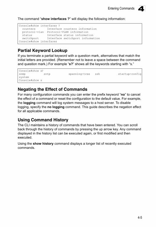
Entering Commands 4
The command “show interfaces ?” will display the following information:Partial Keyword LookupIf you terminate a partial keyword with a question mark, alternatives that match the initial letters are provided. (Remember not to leave a space between the command and question mark.) For example “s?” shows all the keywords starting with “s.”
Negating the Effect of CommandsFor many configuration commands you can enter the prefix keyword “no” to cancel the effect of a command or reset the configuration to the default value. For example, the logging command will log system messages to a host server. To disable logging, specify the no logging command. This guide describes the negation effect for all applicable commands.
Using Command HistoryThe CLI maintains a history of commands that have been entered. You can scroll back through the history of commands by pressing the up arrow key. Any command displayed in the history list can be executed again, or first modified and then executed.
Using the show history command displays a longer list of recently executed commands.
Console#show interfaces ? counters Interface counters information protocol-vlan Protocol-VLAN information status Interface status information switchport Interface switchport informationConsole#show interfaces
Console#show s?snmp sntp spanning-tree ssh startup-configsystemConsole#show s
4-5
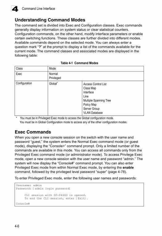
Command Line Interface4
Understanding Command ModesThe command set is divided into Exec and Configuration classes. Exec commands generally display information on system status or clear statistical counters. Configuration commands, on the other hand, modify interface parameters or enable certain switching functions. These classes are further divided into different modes. Available commands depend on the selected mode. You can always enter a question mark “?” at the prompt to display a list of the commands available for the current mode. The command classes and associated modes are displayed in the following table:Exec CommandsWhen you open a new console session on the switch with the user name and password “guest,” the system enters the Normal Exec command mode (or guest mode), displaying the “Console>” command prompt. Only a limited number of the commands are available in this mode. You can access all commands only from the Privileged Exec command mode (or administrator mode). To access Privilege Exec mode, open a new console session with the user name and password “admin.” The system will now display the “Console#” command prompt. You can also enter Privileged Exec mode from within Normal Exec mode, by entering the enable command, followed by the privileged level password “super” (page 4-78).
To enter Privileged Exec mode, enter the following user names and passwords:
Table 4-1 Command Modes
Class Mode
Exec NormalPrivileged
Configuration Global* Access Control ListClass MapInterfaceLineMultiple Spanning TreePolicy MapServer GroupVLAN Database
* You must be in Privileged Exec mode to access the Global configuration mode. You must be in Global Configuration mode to access any of the other configuration modes.
Username: adminPassword: [admin login password]
CLI session with SF-0446G is opened. To end the CLI session, enter [Exit].
Console#
4-6
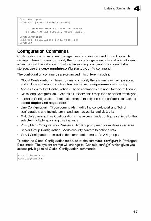
Entering Commands 4
Configuration CommandsConfiguration commands are privileged level commands used to modify switch settings. These commands modify the running configuration only and are not saved when the switch is rebooted. To store the running configuration in non-volatile storage, use the copy running-config startup-config command.
The configuration commands are organized into different modes:
• Global Configuration - These commands modify the system level configuration, and include commands such as hostname and snmp-server community.
• Access Control List Configuration - These commands are used for packet filtering.
• Class Map Configuration - Creates a DiffServ class map for a specified traffic type.
• Interface Configuration - These commands modify the port configuration such as speed-duplex and negotiation.
• Line Configuration - These commands modify the console port and Telnet configuration, and include command such as parity and databits.
• Multiple Spanning Tree Configuration - These commands configure settings for the selected multiple spanning tree instance.
• Policy Map Configuration - Creates a DiffServ policy map for multiple interfaces.
• Server Group Configuration - Adds security servers to defined lists.
• VLAN Configuration - Includes the command to create VLAN groups.
To enter the Global Configuration mode, enter the command configure in Privileged Exec mode. The system prompt will change to “Console(config)#” which gives you access privilege to all Global Configuration commands.
Username: guestPassword: [guest login password]
CLI session with SF-0446G is opened. To end the CLI session, enter [Exit].
Console>enablePassword: [privileged level password]Console#
Console#configureConsole(config)#
4-7
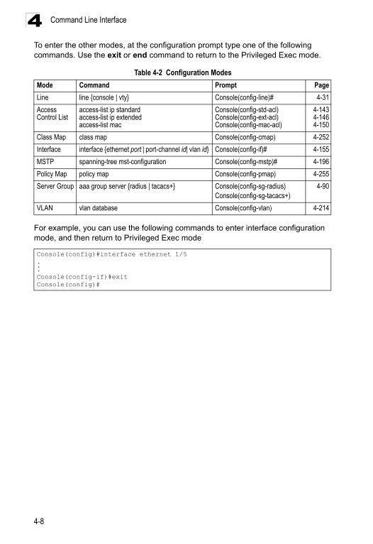
Command Line Interface4
To enter the other modes, at the configuration prompt type one of the following commands. Use the exit or end command to return to the Privileged Exec mode.For example, you can use the following commands to enter interface configuration mode, and then return to Privileged Exec mode
Table 4-2 Configuration Modes
Mode Command Prompt Page
Line line {console | vty} Console(config-line)# 4-31
Access Control List
access-list ip standardaccess-list ip extendedaccess-list mac
Console(config-std-acl)Console(config-ext-acl)Console(config-mac-acl)
4-1434-1464-150
Class Map class map Console(config-cmap) 4-252
Interface interface {ethernet port | port-channel id| vlan id} Console(config-if)# 4-155
MSTP spanning-tree mst-configuration Console(config-mstp)# 4-196
Policy Map policy map Console(config-pmap) 4-255
Server Group aaa group server {radius | tacacs+} Console(config-sg-radius)Console(config-sg-tacacs+)
4-90
VLAN vlan database Console(config-vlan) 4-214
Console(config)#interface ethernet 1/5...Console(config-if)#exitConsole(config)#
4-8
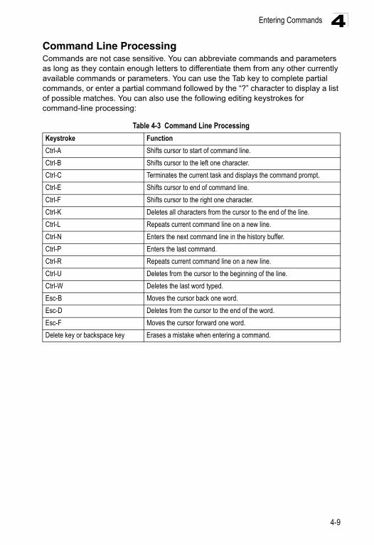
Entering Commands 4
Command Line ProcessingCommands are not case sensitive. You can abbreviate commands and parameters as long as they contain enough letters to differentiate them from any other currently available commands or parameters. You can use the Tab key to complete partial commands, or enter a partial command followed by the “?” character to display a list of possible matches. You can also use the following editing keystrokes for command-line processing:Table 4-3 Command Line Processing
Keystroke Function
Ctrl-A Shifts cursor to start of command line.
Ctrl-B Shifts cursor to the left one character.
Ctrl-C Terminates the current task and displays the command prompt.
Ctrl-E Shifts cursor to end of command line.
Ctrl-F Shifts cursor to the right one character.
Ctrl-K Deletes all characters from the cursor to the end of the line.
Ctrl-L Repeats current command line on a new line.
Ctrl-N Enters the next command line in the history buffer.
Ctrl-P Enters the last command.
Ctrl-R Repeats current command line on a new line.
Ctrl-U Deletes from the cursor to the beginning of the line.
Ctrl-W Deletes the last word typed.
Esc-B Moves the cursor back one word.
Esc-D Deletes from the cursor to the end of the word.
Esc-F Moves the cursor forward one word.
Delete key or backspace key Erases a mistake when entering a command.
4-9
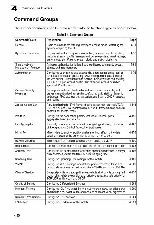
Command Line Interface4
Command GroupsThe system commands can be broken down into the functional groups shown below.
Table 4-4 Command Groups
Command Group Description Page
General Basic commands for entering privileged access mode, restarting the system, or quitting the CLI
4-11
System Management Display and setting of system information, basic modes of operation, maximum frame size, file management, console port and telnet settings, system logs, SMTP alerts, system clock, and switch clustering
4-16
Simple Network Management Protocol
Activates authentication failure traps; configures community access strings, and trap managers
4-61
Authentication Configures user names and passwords, logon access using local or remote authentication (including AAA), management access through the web server, Telnet server and Secure Shell; as well as port security, IEEE 802.1X port access control, and restricted access based on specified IP addresses
4-76
General Security Measures
Segregates traffic for clients attached to common data ports; and prevents unauthorized access by configuring valid static or dynamic addresses, MAC address authentication, and filtering DHCP requests and replies
4-123
Access Control List Provides filtering for IPv4 frames (based on address, protocol, TCP/UDP port number, TCP control code, or non-IP frames (based on MAC address or Ethernet type)
4-143
Interface Configures the connection parameters for all Ethernet ports, aggregated links, and VLANs
4-155
Link Aggregation Statically groups multiple ports into a single logical trunk; configures Link Aggregation Control Protocol for port trunks
4-167
Mirror Port Mirrors data to another port for analysis without affecting the data passing through or the performance of the monitored port
4-178
RSPAN Mirroring Mirrors data from remote switches over a dedicated VLAN 4-180
Rate Limiting Controls the maximum rate for traffic transmitted or received on a port 4-185
Address Table Configures the address table for filtering specified addresses, displays current entries, clears the table, or sets the aging time
4-186
Spanning Tree Configures Spanning Tree settings for the switch 4-190
VLANs Configures VLAN settings, and defines port membership for VLAN groups; also enables or configures private VLANs and protocol VLANs
4-209
Class of Service Sets port priority for untagged frames, selects strict priority or weighted round robin, relative weight for each priority queue, also sets priority for TCP/UDP traffic types, and DSCP
4-238
Quality of Service Configures Differentiated Services 4-251
Multicast Filtering Configures IGMP multicast filtering, query parameters, specifies ports attached to a multicast router, and enables multicast VLAN registration
4-260
Domain Name Service Configures DNS services 4-284
IP Interface Configures IP address for the switch 4-291
4-10
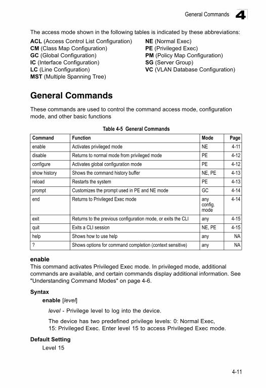
General Commands 4
The access mode shown in the following tables is indicated by these abbreviations:ACL (Access Control List Configuration) NE (Normal Exec)CM (Class Map Configuration) PE (Privileged Exec)GC (Global Configuration) PM (Policy Map Configuration)IC (Interface Configuration) SG (Server Group)LC (Line Configuration) VC (VLAN Database Configuration)MST (Multiple Spanning Tree)
General CommandsThese commands are used to control the command access mode, configuration mode, and other basic functions
enableThis command activates Privileged Exec mode. In privileged mode, additional commands are available, and certain commands display additional information. See "Understanding Command Modes" on page 4-6.
Syntax
enable [level]
level - Privilege level to log into the device.
The device has two predefined privilege levels: 0: Normal Exec, 15: Privileged Exec. Enter level 15 to access Privileged Exec mode.
Default Setting
Level 15
Table 4-5 General Commands
Command Function Mode Page
enable Activates privileged mode NE 4-11
disable Returns to normal mode from privileged mode PE 4-12
configure Activates global configuration mode PE 4-12
show history Shows the command history buffer NE, PE 4-13
reload Restarts the system PE 4-13
prompt Customizes the prompt used in PE and NE mode GC 4-14
end Returns to Privileged Exec mode any config. mode
4-14
exit Returns to the previous configuration mode, or exits the CLI any 4-15
quit Exits a CLI session NE, PE 4-15
help Shows how to use help any NA
? Shows options for command completion (context sensitive) any NA
4-11
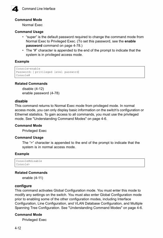
Command Line Interface4
Command ModeNormal Exec
Command Usage
• “super” is the default password required to change the command mode from Normal Exec to Privileged Exec. (To set this password, see the enable password command on page 4-78.)
• The “#” character is appended to the end of the prompt to indicate that the system is in privileged access mode.
Example
Related Commands
disable (4-12)enable password (4-78)
disableThis command returns to Normal Exec mode from privileged mode. In normal access mode, you can only display basic information on the switch's configuration or Ethernet statistics. To gain access to all commands, you must use the privileged mode. See "Understanding Command Modes" on page 4-6.
Command Mode
Privileged Exec
Command Usage
The “>” character is appended to the end of the prompt to indicate that the system is in normal access mode.
Example
Related Commands
enable (4-11)
configureThis command activates Global Configuration mode. You must enter this mode to modify any settings on the switch. You must also enter Global Configuration mode prior to enabling some of the other configuration modes, including Interface Configuration, Line Configuration, and VLAN Database Configuration, and Multiple Spanning Tree Configuration. See "Understanding Command Modes" on page 4-6.
Command Mode
Privileged Exec
Console>enablePassword: [privileged level password]Console#
Console#disableConsole>
4-12
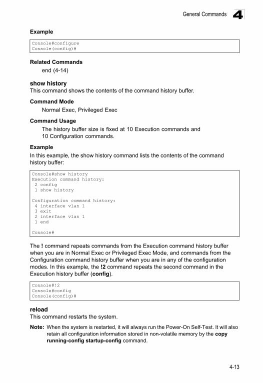
General Commands 4
ExampleRelated Commands
end (4-14)
show historyThis command shows the contents of the command history buffer.
Command Mode
Normal Exec, Privileged Exec
Command Usage
The history buffer size is fixed at 10 Execution commands and 10 Configuration commands.
Example
In this example, the show history command lists the contents of the command history buffer:
The ! command repeats commands from the Execution command history buffer when you are in Normal Exec or Privileged Exec Mode, and commands from the Configuration command history buffer when you are in any of the configuration modes. In this example, the !2 command repeats the second command in the Execution history buffer (config).
reloadThis command restarts the system.
Note: When the system is restarted, it will always run the Power-On Self-Test. It will also retain all configuration information stored in non-volatile memory by the copy running-config startup-config command.
Console#configureConsole(config)#
Console#show historyExecution command history: 2 config 1 show history
Configuration command history: 4 interface vlan 1 3 exit 2 interface vlan 1 1 end
Console#
Console#!2Console#configConsole(config)#
4-13
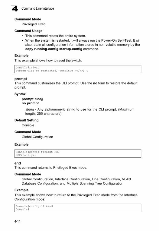
Command Line Interface4
Command ModePrivileged Exec
Command Usage
• This command resets the entire system.• When the system is restarted, it will always run the Power-On Self-Test. It will
also retain all configuration information stored in non-volatile memory by the copy running-config startup-config command.
Example
This example shows how to reset the switch:
promptThis command customizes the CLI prompt. Use the no form to restore the default prompt.
Syntax
prompt stringno prompt
string - Any alphanumeric string to use for the CLI prompt. (Maximum length: 255 characters)
Default Setting
Console
Command Mode
Global Configuration
Example
endThis command returns to Privileged Exec mode.
Command Mode
Global Configuration, Interface Configuration, Line Configuration, VLAN Database Configuration, and Multiple Spanning Tree Configuration
Example
This example shows how to return to the Privileged Exec mode from the Interface Configuration mode:
Console#reloadSystem will be restarted, continue <y/n>? y
Console(config)#prompt RD2RD2(config)#
Console(config-if)#endConsole#
4-14
General Commands 4
exitThis command returns to the previous configuration mode or exit the configuration program.Command Mode
Any
Example
This example shows how to return to the Privileged Exec mode from the Global Configuration mode, and then quit the CLI session:
quitThis command exits the configuration program.
Default Setting
None
Command Mode
Normal Exec, Privileged Exec
Command Usage
The quit and exit commands can both exit the configuration program.
Example
This example shows how to quit a CLI session:
Console(config)#exitConsole#exit
Press ENTER to start sessionUser Access Verification
Username:
Console#quit
Press ENTER to start session
User Access Verification
Username:
4-15
Command Line Interface4
System Management CommandsThese commands are used to control system logs, passwords, user names, browser configuration options, and display or configure a variety of other system information.Device Designation Commands
hostnameThis command specifies or modifies the host name for this device. Use the no form to restore the default host name.
Syntax
hostname nameno hostname
name - The name of this host. (Maximum length: 255 characters)
Default Setting
None
Command Mode
Global Configuration
Table 4-6 System Management Commands
Command Group Function Page
Device Designation Configures information that uniquely identifies this switch 4-16
System Status Displays system configuration, active managers, and version information 4-17
Frame Size Enables support for jumbo frames 4-23
File Management Manages code image or switch configuration files 4-24
Line Sets communication parameters for the serial port, including baud rate and console time-out
4-31
Event Logging Controls logging of error messages 4-40
SMTP Alerts Configures SMTP email alerts 4-47
Time (System Clock) Sets the system clock automatically via NTP/SNTP server or manually 4-51
Switch Clustering Configures management of multiple devices via a single IP address 4-56
Table 4-7 Device Designation Commands
Command Function Mode Page
prompt Customizes the prompt used in PE and NE mode GC 4-14
hostname Specifies the host name for the switch GC 4-16
snmp-server contact Sets the system contact string GC 4-64
snmp-server location Sets the system location string GC 4-64
4-16
System Management Commands 4
ExampleSystem Status CommandsThis section describes commands used to display system information.
show startup-configThis command displays the configuration file stored in non-volatile memory that is used to start up the system.
Command Mode
Privileged Exec
Command Usage
• Use this command in conjunction with the show running-config command to compare the information in running memory to the information stored in non-volatile memory.
• This command displays settings for key command modes. Each mode group is separated by “!” symbols, and includes the configuration mode command, and corresponding commands. This command displays the following information:
- Switch’s MAC address- SNTP server settings- Local time zone- SNMP community strings- Users (names and access levels)- VLAN database (VLAN ID, name and state)- VLAN configuration settings for each interface- Multiple spanning tree instances (name and interfaces)- Interface settings- IP address configured for the switch- Any configured settings for the console port and Telnet
Console(config)#hostname RD#1Console(config)#
Table 4-8 System Status Commands
Command Function Mode Page
show startup-config Displays the contents of the configuration file (stored in flash memory) that is used to start up the system
PE 4-17
show running-config Displays the configuration data currently in use PE 4-18
show system Displays system information NE, PE 4-21
show users Shows all active console, SSH, Telnet and web sessions, including user name, idle time, and IP address of network clients
NE, PE 4-21
show version Displays version information for the system NE, PE 4-22
4-17
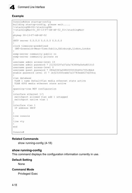
Command Line Interface4
ExampleRelated Commands
show running-config (4-18)
show running-configThis command displays the configuration information currently in use.
Default Setting
None
Command Mode
Privileged Exec
Console#show startup-configbuilding startup-config, please wait.....!<stackingDB>00</stackingDB>!<stackingMac>01_00-13-F7-A8-AF-52_01</stackingMac>!phymap 00-13-F7-A8-AF-52!SNTP server 0.0.0.0 0.0.0.0 0.0.0.0!clock timezone-predefined GMT-Greenwich-Mean-Time:Dublin,Edinburgh,Lisbon,London
!snmp-server community public rosnmp-server community private rw!username admin access-level 15username admin password 7 21232f297a57a5a743894a0e4a801fc3username guest access-level 0username guest password 7 084e0343a0486ff05530df6c705c8bb4enable password level 15 7 1b3231655cebb7a1f783eddf27d254ca!vlan database VLAN 1 name DefaultVlan media ethernet state active VLAN 4093 media ethernet state active!spanning-tree MST configuration!interface ethernet 1/1 switchport allowed vlan add 1 untagged switchport native vlan 1...interface vlan 1 IP address DHCP
!line console!line vty!end
Console#
4-18
System Management Commands 4
Command Usage• Use this command in conjunction with the show startup-config command to compare the information in running memory to the information stored in non-volatile memory.
• This command displays settings for key command modes. Each mode group is separated by “!” symbols, and includes the configuration mode command, and corresponding commands. This command displays the following information:
- Switch’s MAC address- SNTP server settings- Time zone- SNMP community strings- Users (names and access levels)- VLAN database (VLAN ID, name and state)- VLAN configuration settings for each interface- Multiple spanning tree instances (name and interfaces)- Interface settings- IP address configured for the switch- Any configured settings for the console port and Telnet
4-19
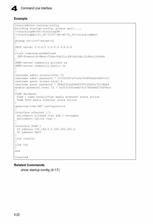
Command Line Interface4
ExampleRelated Commands
show startup-config (4-17)
Console#show running-configbuilding startup-config, please wait.....!<stackingDB>00</stackingDB>!<stackingMac>01_00-13-F7-A8-AF-52_01</stackingMac>!phymap 00-13-F7-A8-AF-52!SNTP server 0.0.0.0 0.0.0.0 0.0.0.0!clock timezone-predefined GMT-Greenwich-Mean-Time:Dublin,Edinburgh,Lisbon,London
!SNMP-server community private rwSNMP-server community public ro!!username admin access-level 15username admin password 7 21232f297a57a5a743894a0e4a801fc3username guest access-level 0username guest password 7 084e0343a0486ff05530df6c705c8bb4enable password level 15 7 1b3231655cebb7a1f783eddf27d254ca!VLAN database VLAN 1 name DefaultVlan media ethernet state active VLAN 4093 media ethernet state active!spanning-tree MST configuration!interface ethernet 1/1 switchport allowed vlan add 1 untagged switchport native vlan 1...interface VLAN 1 IP address 192.168.0.2 255.255.255.0 IP address DHCP!line console!line vty!end
Console#
4-20
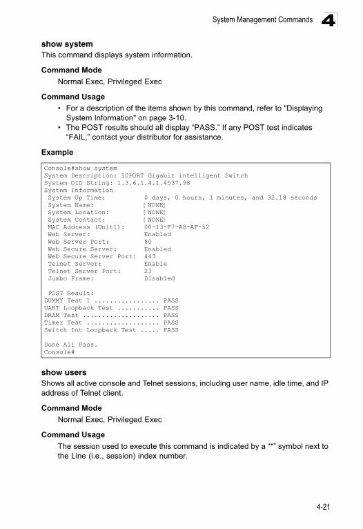
System Management Commands 4
show systemThis command displays system information.Command Mode
Normal Exec, Privileged Exec
Command Usage
• For a description of the items shown by this command, refer to "Displaying System Information" on page 3-10.
• The POST results should all display “PASS.” If any POST test indicates “FAIL,” contact your distributor for assistance.
Example
show usersShows all active console and Telnet sessions, including user name, idle time, and IP address of Telnet client.
Command Mode
Normal Exec, Privileged Exec
Command Usage
The session used to execute this command is indicated by a “*” symbol next to the Line (i.e., session) index number.
Console#show systemSystem Description: 50PORT Gigabit intelligent SwitchSystem OID String: 1.3.6.1.4.1.4537.98System Information System Up Time: 0 days, 0 hours, 1 minutes, and 32.18 seconds System Name: [NONE] System Location: [NONE] System Contact: [NONE] MAC Address (Unit1): 00-13-F7-A8-AF-52 Web Server: Enabled Web Server Port: 80 Web Secure Server: Enabled Web Secure Server Port: 443 Telnet Server: Enable Telnet Server Port: 23 Jumbo Frame: Disabled
POST Result:DUMMY Test 1 ................. PASSUART Loopback Test ........... PASSDRAM Test .................... PASSTimer Test ................... PASSSwitch Int Loopback Test ..... PASS
Done All Pass.Console#
4-21
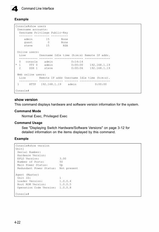
Command Line Interface4
Exampleshow versionThis command displays hardware and software version information for the system.
Command Mode
Normal Exec, Privileged Exec
Command Usage
See "Displaying Switch Hardware/Software Versions" on page 3-12 for detailed information on the items displayed by this command.
Example
Console#show users Username accounts: Username Privilege Public-Key -------- --------- ---------- admin 15 None guest 0 None steve 15 RSA
Online users: Line Username Idle time (h:m:s) Remote IP addr. ----------- -------- ----------------- --------------- 0 console admin 0:14:14* 1 VTY 0 admin 0:00:00 192.168.1.19 2 SSH 1 steve 0:00:06 192.168.1.19
Web online users: Line Remote IP addr Username Idle time (h:m:s). ----------- -------------- -------- ------------------ 1 HTTP 192.168.1.19 admin 0:00:00
Console#
Console#show versionUnit1 Serial Number: Hardware Version: EPLD Version: 3.00 Number of Ports: 50 Main Power Status: Up Redundant Power Status: Not present
Agent (Master) Unit ID: 1 Loader Version: 1.0.0.4 Boot ROM Version: 1.0.0.5 Operation Code Version: 1.0.0.8
Console#
4-22
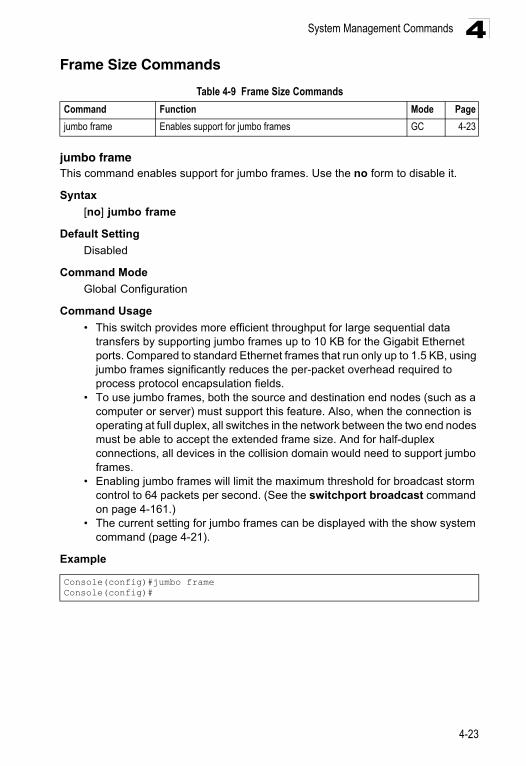
System Management Commands 4
Frame Size Commandsjumbo frameThis command enables support for jumbo frames. Use the no form to disable it.
Syntax
[no] jumbo frame
Default Setting
Disabled
Command Mode
Global Configuration
Command Usage
• This switch provides more efficient throughput for large sequential data transfers by supporting jumbo frames up to 10 KB for the Gigabit Ethernet ports. Compared to standard Ethernet frames that run only up to 1.5 KB, using jumbo frames significantly reduces the per-packet overhead required to process protocol encapsulation fields.
• To use jumbo frames, both the source and destination end nodes (such as a computer or server) must support this feature. Also, when the connection is operating at full duplex, all switches in the network between the two end nodes must be able to accept the extended frame size. And for half-duplex connections, all devices in the collision domain would need to support jumbo frames.
• Enabling jumbo frames will limit the maximum threshold for broadcast storm control to 64 packets per second. (See the switchport broadcast command on page 4-161.)
• The current setting for jumbo frames can be displayed with the show system command (page 4-21).
Example
Table 4-9 Frame Size Commands
Command Function Mode Page
jumbo frame Enables support for jumbo frames GC 4-23
Console(config)#jumbo frameConsole(config)#
4-23
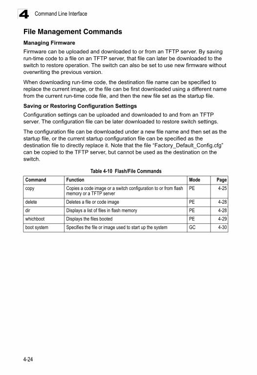
Command Line Interface4
File Management CommandsManaging FirmwareFirmware can be uploaded and downloaded to or from an TFTP server. By saving run-time code to a file on an TFTP server, that file can later be downloaded to the switch to restore operation. The switch can also be set to use new firmware without overwriting the previous version.
When downloading run-time code, the destination file name can be specified to replace the current image, or the file can be first downloaded using a different name from the current run-time code file, and then the new file set as the startup file.
Saving or Restoring Configuration Settings
Configuration settings can be uploaded and downloaded to and from an TFTP server. The configuration file can be later downloaded to restore switch settings.
The configuration file can be downloaded under a new file name and then set as the startup file, or the current startup configuration file can be specified as the destination file to directly replace it. Note that the file “Factory_Default_Config.cfg” can be copied to the TFTP server, but cannot be used as the destination on the switch.
Table 4-10 Flash/File Commands
Command Function Mode Page
copy Copies a code image or a switch configuration to or from flash memory or a TFTP server
PE 4-25
delete Deletes a file or code image PE 4-28
dir Displays a list of files in flash memory PE 4-28
whichboot Displays the files booted PE 4-29
boot system Specifies the file or image used to start up the system GC 4-30
4-24
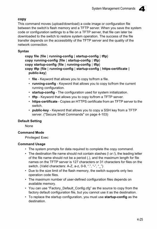
System Management Commands 4
copyThis command moves (upload/download) a code image or configuration file between the switch’s flash memory and a TFTP server. When you save the system code or configuration settings to a file on a TFTP server, that file can later be downloaded to the switch to restore system operation. The success of the file transfer depends on the accessibility of the TFTP server and the quality of the network connection.Syntax
copy file {file | running-config | startup-config | tftp}copy running-config {file | startup-config | tftp}copy startup-config {file | running-config | tftp}copy tftp {file | running-config | startup-config | https-certificate |
public-key}
• file - Keyword that allows you to copy to/from a file. • running-config - Keyword that allows you to copy to/from the current
running configuration. • startup-config - The configuration used for system initialization. • tftp - Keyword that allows you to copy to/from a TFTP server.• https-certificate - Copies an HTTPS certificate from an TFTP server to the
switch.• public-key - Keyword that allows you to copy a SSH key from a TFTP
server. ("Secure Shell Commands" on page 4-103)
Default Setting
None
Command Mode
Privileged Exec
Command Usage
• The system prompts for data required to complete the copy command. • The destination file name should not contain slashes (\ or /), the leading letter
of the file name should not be a period (.), and the maximum length for file names on the TFTP server is 127 characters or 31 characters for files on the switch. (Valid characters: A-Z, a-z, 0-9, “.”, “-”, “_”)
• Due to the size limit of the flash memory, the switch supports only two operation code files.
• The maximum number of user-defined configuration files depends on available memory.
• You can use “Factory_Default_Config.cfg” as the source to copy from the factory default configuration file, but you cannot use it as the destination.
• To replace the startup configuration, you must use startup-config as the destination.
4-25
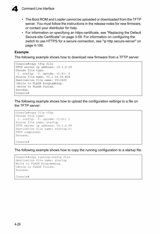
Command Line Interface4
• The Boot ROM and Loader cannot be uploaded or downloaded from the TFTPserver. You must follow the instructions in the release notes for new firmware, or contact your distributor for help.
• For information on specifying an https-certificate, see "Replacing the Default Secure-site Certificate" on page 3-59. For information on configuring the switch to use HTTPS for a secure connection, see "ip http secure-server" on page 4-100.
Example
The following example shows how to download new firmware from a TFTP server:
The following example shows how to upload the configuration settings to a file on the TFTP server:
The following example shows how to copy the running configuration to a startup file.
Console#copy tftp fileTFTP server ip address: 10.1.0.19Choose file type: 1. config: 2. opcode: <1-2>: 2Source file name: V3.1.16.20.BIXDestination file name: V311620\Write to FLASH Programming.-Write to FLASH finish.Success.Console#
Console#copy file tftpChoose file type: 1. config: 2. opcode: <1-2>: 1Source file name: startupTFTP server ip address: 10.1.0.99Destination file name: startup.01TFTP completed.Success.
Console#
Console#copy running-config filedestination file name: startupWrite to FLASH Programming.\Write to FLASH finish.Success.
Console#
4-26
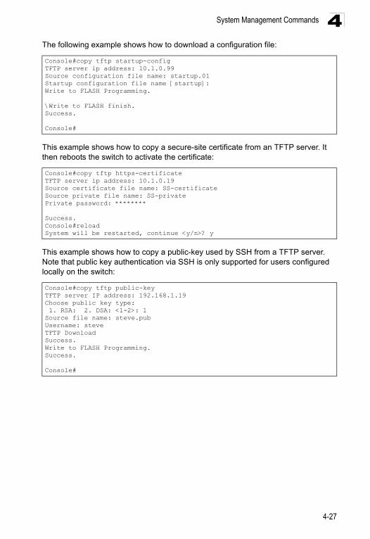
System Management Commands 4
The following example shows how to download a configuration file:This example shows how to copy a secure-site certificate from an TFTP server. It then reboots the switch to activate the certificate:
This example shows how to copy a public-key used by SSH from a TFTP server. Note that public key authentication via SSH is only supported for users configured locally on the switch:
Console#copy tftp startup-configTFTP server ip address: 10.1.0.99Source configuration file name: startup.01Startup configuration file name [startup]:Write to FLASH Programming.
\Write to FLASH finish.Success.
Console#
Console#copy tftp https-certificateTFTP server ip address: 10.1.0.19Source certificate file name: SS-certificateSource private file name: SS-privatePrivate password: ********
Success.Console#reloadSystem will be restarted, continue <y/n>? y
Console#copy tftp public-keyTFTP server IP address: 192.168.1.19Choose public key type: 1. RSA: 2. DSA: <1-2>: 1Source file name: steve.pubUsername: steveTFTP DownloadSuccess.Write to FLASH Programming.Success.
Console#
4-27
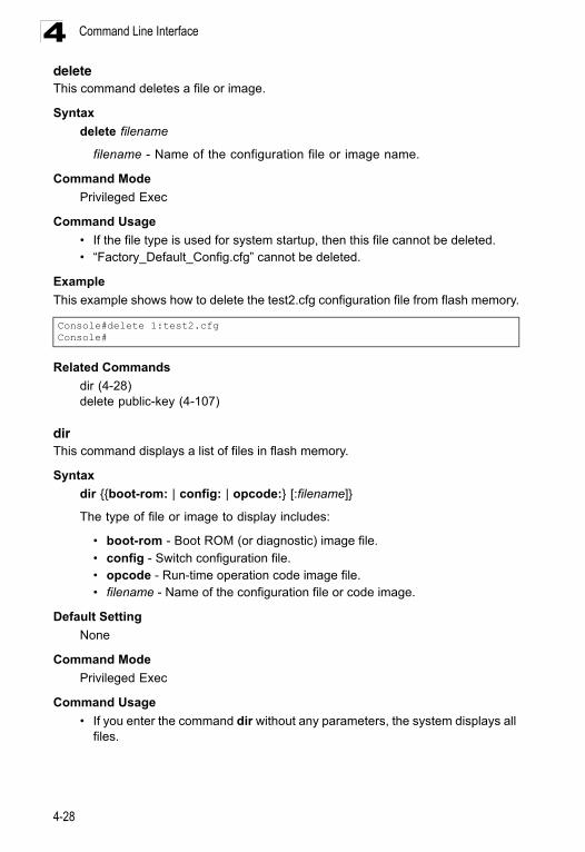
Command Line Interface4
deleteThis command deletes a file or image.Syntax
delete filename
filename - Name of the configuration file or image name.
Command Mode
Privileged Exec
Command Usage
• If the file type is used for system startup, then this file cannot be deleted. • “Factory_Default_Config.cfg” cannot be deleted.
Example
This example shows how to delete the test2.cfg configuration file from flash memory.
Related Commands
dir (4-28)delete public-key (4-107)
dirThis command displays a list of files in flash memory.
Syntax
dir {{boot-rom: | config: | opcode:} [:filename]}
The type of file or image to display includes:
• boot-rom - Boot ROM (or diagnostic) image file.
• config - Switch configuration file.• opcode - Run-time operation code image file. • filename - Name of the configuration file or code image.
Default Setting
None
Command Mode
Privileged Exec
Command Usage
• If you enter the command dir without any parameters, the system displays all files.
Console#delete 1:test2.cfgConsole#
4-28
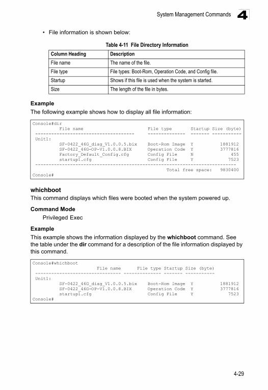
System Management Commands 4
• File information is shown below:Example
The following example shows how to display all file information:
whichbootThis command displays which files were booted when the system powered up.
Command Mode
Privileged Exec
Example
This example shows the information displayed by the whichboot command. See the table under the dir command for a description of the file information displayed by this command.
Table 4-11 File Directory Information
Column Heading Description
File name The name of the file.
File type File types: Boot-Rom, Operation Code, and Config file.
Startup Shows if this file is used when the system is started.
Size The length of the file in bytes.
Console#dir File name File type Startup Size (byte) ------------------------------------- -------------- ------- ----------- Unit1: SF-0422_46G_diag_V1.0.0.5.bix Boot-Rom Image Y 1881912 SF-0422_46G-OP-V1.0.0.8.BIX Operation Code Y 3777816 Factory_Default_Config.cfg Config File N 455 startup1.cfg Config File Y 7523 --------------------------------------------------------------------------- Total free space: 9830400Console#
Console#whichboot File name File type Startup Size (byte) -------------------------------- -------------- ------- ----------- Unit1: SF-0422_46G_diag_V1.0.0.5.bix Boot-Rom Image Y 1881912 SF-0422_46G-OP-V1.0.0.8.BIX Operation Code Y 3777816 startup1.cfg Config File Y 7523Console#
4-29
Command Line Interface4
boot systemThis command specifies the image used to start up the system.Syntax
boot system {boot-rom| config | opcode}: filename
The type of file or image to set as a default includes:
• boot-rom* - Boot ROM.• config* - Configuration file.• opcode* - Run-time operation code.• filename - Name of the configuration file or code image.
* The colon (:) is required.
Default Setting
None
Command Mode
Global Configuration
Command Usage
• A colon (:) is required after the specified unit number and file type. • If the file contains an error, it cannot be set as the default file.
Example
Related Commands
dir (4-28)whichboot (4-29)
Console(config)#boot system config: startupConsole(config)#
4-30
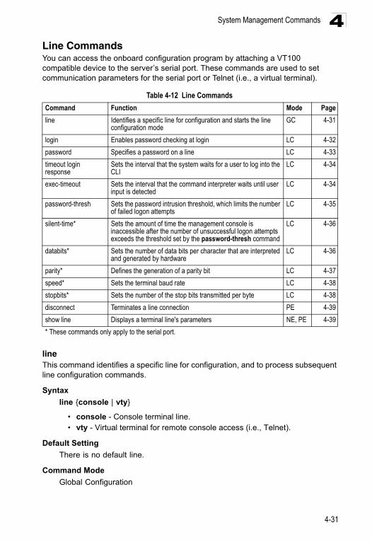
System Management Commands 4
Line CommandsYou can access the onboard configuration program by attaching a VT100 compatible device to the server’s serial port. These commands are used to set communication parameters for the serial port or Telnet (i.e., a virtual terminal).lineThis command identifies a specific line for configuration, and to process subsequent line configuration commands.
Syntax
line {console | vty}
• console - Console terminal line. • vty - Virtual terminal for remote console access (i.e., Telnet).
Default Setting
There is no default line.
Command Mode
Global Configuration
Table 4-12 Line Commands
Command Function Mode Page
line Identifies a specific line for configuration and starts the line configuration mode
GC 4-31
login Enables password checking at login LC 4-32
password Specifies a password on a line LC 4-33
timeout login response
Sets the interval that the system waits for a user to log into the CLI
LC 4-34
exec-timeout Sets the interval that the command interpreter waits until user input is detected
LC 4-34
password-thresh Sets the password intrusion threshold, which limits the number of failed logon attempts
LC 4-35
silent-time* Sets the amount of time the management console is inaccessible after the number of unsuccessful logon attempts exceeds the threshold set by the password-thresh command
LC 4-36
databits* Sets the number of data bits per character that are interpreted and generated by hardware
LC 4-36
parity* Defines the generation of a parity bit LC 4-37
speed* Sets the terminal baud rate LC 4-38
stopbits* Sets the number of the stop bits transmitted per byte LC 4-38
disconnect Terminates a line connection PE 4-39
show line Displays a terminal line's parameters NE, PE 4-39
* These commands only apply to the serial port.
4-31
Command Line Interface4
Command UsageTelnet is considered a virtual terminal connection and will be shown as “Vty” in screen displays such as show users. However, the serial communication parameters (e.g., databits) do not affect Telnet connections.
Example
To enter console line mode, enter the following command:
Related Commands
show line (4-39)show users (4-21)
loginThis command enables password checking at login. Use the no form to disable password checking and allow connections without a password.
Syntax
login [local] no login
local - Selects local password checking. Authentication is based on the user name specified with the username command.
Default Setting
login local
Command Mode
Line Configuration
Command Usage
• There are three authentication modes provided by the switch itself at login:
- login selects authentication by a single global password as specified by the password line configuration command. When using this method, the management interface starts in Normal Exec (NE) mode.
- login local selects authentication via the user name and password specified by the username command (i.e., default setting). When using this method, the management interface starts in Normal Exec (NE) or Privileged Exec (PE) mode, depending on the user’s privilege level (0 - NE, 15 - PE).
- no login selects no authentication. When using this method, the management interface starts in Normal Exec (NE) mode.
• This command controls login authentication via the switch itself. To configure user names and passwords for remote authentication servers, you must use the RADIUS or TACACS software installed on those servers.
Console(config)#line consoleConsole(config-line)#
4-32
System Management Commands 4
ExampleRelated Commands
username (4-77)password (4-33)
passwordThis command specifies the password for a line. Use the no form to remove the password.
Syntax
password {0 | 7} passwordno password
• {0 | 7} - 0 means plain password, 7 means encrypted password• password - Character string that specifies the line password.
(Maximum length: 8 characters plain text, 32 encrypted, case sensitive)
Default Setting
No password is specified.
Command Mode
Line Configuration
Command Usage
• When a connection is started on a line with password protection, the system prompts for the password. If you enter the correct password, the system shows a prompt. You can use the password-thresh command to set the number of times a user can enter an incorrect password before the system terminates the line connection and returns the terminal to the idle state.
• The encrypted password is required for compatibility with legacy password settings (i.e., plain text or encrypted) when reading the configuration file during system bootup or when downloading the configuration file from a TFTP server. There is no need for you to manually configure encrypted passwords.
Example
Related Commands
login (4-32)password-thresh (4-35)
Console(config-line)#login localConsole(config-line)#
Console(config-line)#password 0 secretConsole(config-line)#
4-33
Command Line Interface4
timeout login responseThis command sets the interval that the system waits for a user to log into the CLI. Use the no form to restore the default.Syntax
timeout login response [seconds]no timeout login response
seconds - Integer that specifies the timeout interval. (Range: 0 - 300 seconds; 0: disabled)
Default Setting
• CLI: Disabled (0 seconds)• Telnet: 600 seconds
Command Mode
Line Configuration
Command Usage
• If a login attempt is not detected within the timeout interval, the connection is terminated for the session.
• This command applies to both the local console and Telnet connections.• The timeout for Telnet cannot be disabled.• Using the command without specifying a timeout restores the default setting.
Example
To set the timeout to two minutes, enter this command:
Related Commands
silent-time (4-36)exec-timeout (4-14)
exec-timeoutThis command sets the interval that the system waits until user input is detected. Use the no form to restore the default.
Syntax
exec-timeout [seconds]no exec-timeout
seconds - Integer that specifies the number of seconds. (Range: 0-65535 seconds; 0: no timeout)
Default Setting
10 minutes
Console(config-line)#timeout login response 120Console(config-line)#
4-34
System Management Commands 4
Command ModeLine Configuration
Command Usage
• If user input is detected within the timeout interval, the session is kept open; otherwise the session is terminated.
• This command applies to both the local console and Telnet connections.• The timeout for Telnet cannot be disabled.• Using the command without specifying a timeout restores the default setting.
Example
To set the timeout to two minutes, enter this command:
Related Commands
silent-time (4-36)timeout login response (4-13)
password-threshThis command sets the password intrusion threshold which limits the number of failed logon attempts. Use the no form to remove the threshold value.
Syntax
password-thresh [threshold]no password-thresh
threshold - The number of allowed password attempts. (Range: 1-120; 0: no threshold)
Default Setting
The default value is three attempts.
Command Mode
Line Configuration
Command Usage
• When the logon attempt threshold is reached, the system interface becomes silent for a specified amount of time before allowing the next logon attempt. (Use the silent-time command to set this interval.) When this threshold is reached for Telnet, the Telnet logon interface shuts down.
• This command applies to both the local console and Telnet connections.
Example
To set the password threshold to five attempts, enter this command:
Console(config-line)#exec-timeout 120Console(config-line)#
Console(config-line)#password-thresh 5Console(config-line)#
4-35
Command Line Interface4
Related Commandssilent-time (4-36)timeout login response (4-13)
silent-timeThis command sets the amount of time the management console is inaccessible after the number of unsuccessful logon attempts exceeds the threshold set by the password-thresh command. Use the no form to remove the silent time value.
Syntax
silent-time [seconds]no silent-time
seconds - The number of seconds to disable console response. (Range: 0-65535; 0: no silent-time)
Default Setting
The default value is no silent-time.
Command Mode
Line Configuration
Example
To set the silent time to 60 seconds, enter this command:
Related Commands
password-thresh (4-35)
databitsThis command sets the number of data bits per character that are interpreted and generated by the console port. Use the no form to restore the default value.
Syntax
databits {7 | 8}no databits
• 7 - Seven data bits per character. • 8 - Eight data bits per character.
Default Setting
8 data bits per character
Command Mode
Line Configuration
Console(config-line)#silent-time 60Console(config-line)#
4-36
System Management Commands 4
Command UsageThe databits command can be used to mask the high bit on input from devices that generate 7 data bits with parity. If parity is being generated, specify 7 data bits per character. If no parity is required, specify 8 data bits per character.
Example
To specify 7 data bits, enter this command:
Related Commands
parity (4-37)
parityThis command defines the generation of a parity bit. Use the no form to restore the default setting.
Syntax
parity {none | even | odd}no parity
• none - No parity • even - Even parity • odd - Odd parity
Default Setting
No parity
Command Mode
Line Configuration
Command Usage
Communication protocols provided by devices such as terminals and modems often require a specific parity bit setting.
Example
To specify no parity, enter this command:
Console(config-line)#databits 7Console(config-line)#
Console(config-line)#parity noneConsole(config-line)#
4-37
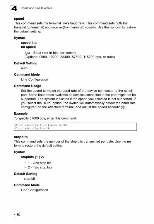
Command Line Interface4
speedThis command sets the terminal line’s baud rate. This command sets both the transmit (to terminal) and receive (from terminal) speeds. Use the no form to restore the default setting.Syntax
speed bpsno speed
bps - Baud rate in bits per second. (Options: 9600, 19200, 38400, 57600, 115200 bps, or auto)
Default Setting
auto
Command Mode
Line Configuration
Command Usage
Set the speed to match the baud rate of the device connected to the serial port. Some baud rates available on devices connected to the port might not be supported. The system indicates if the speed you selected is not supported. If you select the “auto” option, the switch will automatically detect the baud rate configured on the attached terminal, and adjust the speed accordingly.
Example
To specify 57600 bps, enter this command:
stopbitsThis command sets the number of the stop bits transmitted per byte. Use the no form to restore the default setting.
Syntax
stopbits {1 | 2}
• 1 - One stop bit • 2 - Two stop bits
Default Setting
1 stop bit
Command Mode
Line Configuration
Console(config-line)#speed 57600Console(config-line)#
4-38
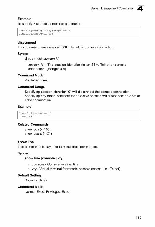
System Management Commands 4
ExampleTo specify 2 stop bits, enter this command:
disconnectThis command terminates an SSH, Telnet, or console connection.
Syntax
disconnect session-id
session-id – The session identifier for an SSH, Telnet or console connection. (Range: 0-4)
Command Mode
Privileged Exec
Command Usage
Specifying session identifier “0” will disconnect the console connection. Specifying any other identifiers for an active session will disconnect an SSH or Telnet connection.
Example
Related Commands
show ssh (4-110)show users (4-21)
show lineThis command displays the terminal line’s parameters.
Syntax
show line [console | vty]
• console - Console terminal line.• vty - Virtual terminal for remote console access (i.e., Telnet).
Default Setting
Shows all lines
Command Mode
Normal Exec, Privileged Exec
Console(config-line)#stopbits 2Console(config-line)#
Console#disconnect 1Console#
4-39
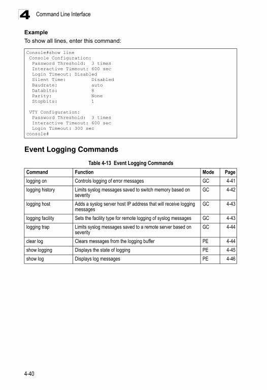
Command Line Interface4
ExampleTo show all lines, enter this command:
Event Logging Commands
Console#show line Console Configuration: Password Threshold: 3 times Interactive Timeout: 600 sec Login Timeout: Disabled Silent Time: Disabled Baudrate: auto Databits: 8 Parity: None Stopbits: 1
VTY Configuration: Password Threshold: 3 times Interactive Timeout: 600 sec Login Timeout: 300 secconsole#
Table 4-13 Event Logging Commands
Command Function Mode Page
logging on Controls logging of error messages GC 4-41
logging history Limits syslog messages saved to switch memory based on severity
GC 4-42
logging host Adds a syslog server host IP address that will receive logging messages
GC 4-43
logging facility Sets the facility type for remote logging of syslog messages GC 4-43
logging trap Limits syslog messages saved to a remote server based on severity
GC 4-44
clear log Clears messages from the logging buffer PE 4-44
show logging Displays the state of logging PE 4-45
show log Displays log messages PE 4-46
4-40
System Management Commands 4
logging onThis command controls logging of error messages, sending debug or error messages to switch memory. The no form disables the logging process.Syntax
[no] logging on
Default Setting
None
Command Mode
Global Configuration
Command Usage
The logging process controls error messages saved to switch memory or sent to remote syslog servers. You can use the logging history command to control the type of error messages that are stored in memory. You can use the logging trap command to control the type of error messages that are sent to specified syslog servers.
Example
Related Commands
logging history (4-42)logging trap (4-44)clear log (4-44)
Console(config)#logging onConsole(config)#
4-41
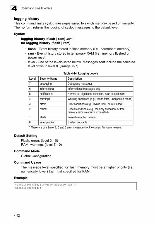
Command Line Interface4
logging historyThis command limits syslog messages saved to switch memory based on severity. The no form returns the logging of syslog messages to the default level.Syntax
logging history {flash | ram} levelno logging history {flash | ram}
• flash - Event history stored in flash memory (i.e., permanent memory). • ram - Event history stored in temporary RAM (i.e., memory flushed on
power reset). • level - One of the levels listed below. Messages sent include the selected
level down to level 0. (Range: 0-7)
Default Setting
Flash: errors (level 3 - 0)RAM: warnings (level 7 - 0)
Command Mode
Global Configuration
Command Usage
The message level specified for flash memory must be a higher priority (i.e., numerically lower) than that specified for RAM.
Example
Table 4-14 Logging Levels
Level Severity Name Description
7 debugging Debugging messages
6 informational Informational messages only
5 notifications Normal but significant condition, such as cold start
4 warnings Warning conditions (e.g., return false, unexpected return)
3 errors Error conditions (e.g., invalid input, default used)
2 critical Critical conditions (e.g., memory allocation, or free memory error - resource exhausted)
1 alerts Immediate action needed
0 emergencies System unusable
* There are only Level 2, 5 and 6 error messages for the current firmware release.
Console(config)#logging history ram 0Console(config)#
4-42
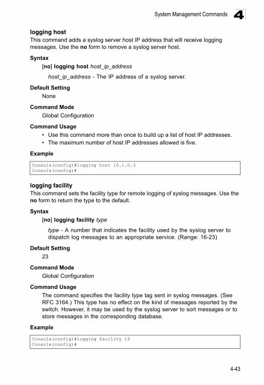
System Management Commands 4
logging hostThis command adds a syslog server host IP address that will receive logging messages. Use the no form to remove a syslog server host.Syntax
[no] logging host host_ip_address
host_ip_address - The IP address of a syslog server.
Default Setting
None
Command Mode
Global Configuration
Command Usage
• Use this command more than once to build up a list of host IP addresses.• The maximum number of host IP addresses allowed is five.
Example
logging facilityThis command sets the facility type for remote logging of syslog messages. Use the no form to return the type to the default.
Syntax
[no] logging facility type
type - A number that indicates the facility used by the syslog server to dispatch log messages to an appropriate service. (Range: 16-23)
Default Setting
23
Command Mode
Global Configuration
Command Usage
The command specifies the facility type tag sent in syslog messages. (See RFC 3164.) This type has no effect on the kind of messages reported by the switch. However, it may be used by the syslog server to sort messages or to store messages in the corresponding database.
Example
Console(config)#logging host 10.1.0.3Console(config)#
Console(config)#logging facility 19Console(config)#
4-43
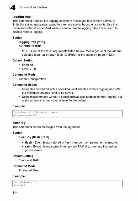
Command Line Interface4
logging trapThis command enables the logging of system messages to a remote server, or limits the syslog messages saved to a remote server based on severity. Use this command without a specified level to enable remote logging. Use the no form to disable remote logging.Syntax
logging trap [level]no logging trap
level - One of the level arguments listed below. Messages sent include the selected level up through level 0. (Refer to the table on page 4-42.)
Default Setting
• Enabled• Level 7 - 0
Command Mode
Global Configuration
Command Usage
• Using this command with a specified level enables remote logging and sets the minimum severity level to be saved.
• Using this command without a specified level also enables remote logging, but restores the minimum severity level to the default.
Example
clear logThis command clears messages from the log buffer.
Syntax
clear log [flash | ram]
• flash - Event history stored in flash memory (i.e., permanent memory). • ram - Event history stored in temporary RAM (i.e., memory flushed on
power reset).
Default Setting
Flash and RAM
Command Mode
Privileged Exec
Example
Console(config)#logging trap 4Console(config)#
Console#clear logConsole#
4-44
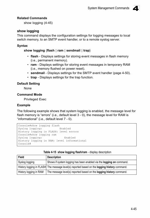
System Management Commands 4
Related Commandsshow logging (4-45)
show loggingThis command displays the configuration settings for logging messages to local switch memory, to an SMTP event handler, or to a remote syslog server.
Syntax
show logging {flash | ram | sendmail | trap}
• flash - Displays settings for storing event messages in flash memory(i.e., permanent memory).
• ram - Displays settings for storing event messages in temporary RAM (i.e., memory flushed on power reset).
• sendmail - Displays settings for the SMTP event handler (page 4-50).• trap - Displays settings for the trap function.
Default Setting
None
Command Mode
Privileged Exec
Example
The following example shows that system logging is enabled, the message level for flash memory is “errors” (i.e., default level 3 - 0), the message level for RAM is “informational” (i.e., default level 7 - 0).
Console#show logging flashSyslog logging: EnabledHistory logging in FLASH: level errorsConsole#show logging ramSyslog logging: EnabledHistory logging in RAM: level informationalConsole#
Table 4-15 show logging flash/ram - display description
Field Description
Syslog logging Shows if system logging has been enabled via the logging on command.
History logging in FLASH The message level(s) reported based on the logging history command.
History logging in RAM The message level(s) reported based on the logging history command.
4-45
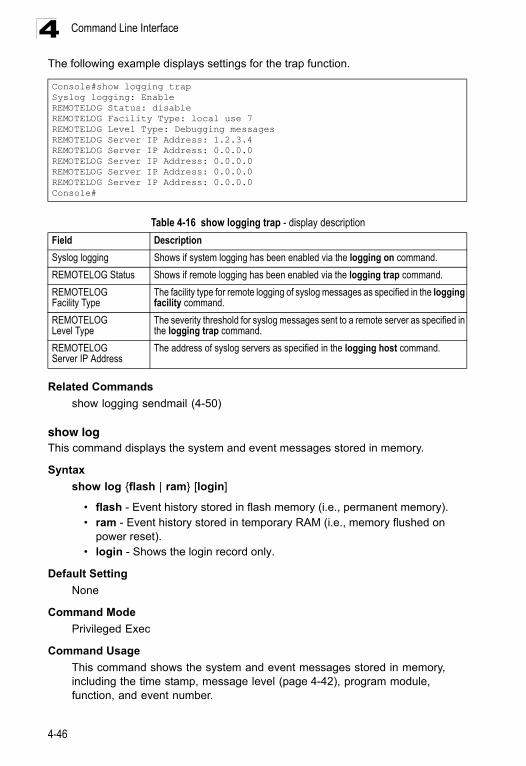
Command Line Interface4
The following example displays settings for the trap function.Related Commands
show logging sendmail (4-50)
show logThis command displays the system and event messages stored in memory.
Syntax
show log {flash | ram} [login]
• flash - Event history stored in flash memory (i.e., permanent memory). • ram - Event history stored in temporary RAM (i.e., memory flushed on
power reset). • login - Shows the login record only.
Default Setting
None
Command Mode
Privileged Exec
Command Usage
This command shows the system and event messages stored in memory, including the time stamp, message level (page 4-42), program module, function, and event number.
Console#show logging trapSyslog logging: EnableREMOTELOG Status: disableREMOTELOG Facility Type: local use 7REMOTELOG Level Type: Debugging messagesREMOTELOG Server IP Address: 1.2.3.4REMOTELOG Server IP Address: 0.0.0.0REMOTELOG Server IP Address: 0.0.0.0REMOTELOG Server IP Address: 0.0.0.0REMOTELOG Server IP Address: 0.0.0.0Console#
Table 4-16 show logging trap - display description
Field Description
Syslog logging Shows if system logging has been enabled via the logging on command.
REMOTELOG Status Shows if remote logging has been enabled via the logging trap command.
REMOTELOG Facility Type
The facility type for remote logging of syslog messages as specified in the logging facility command.
REMOTELOG Level Type
The severity threshold for syslog messages sent to a remote server as specified in the logging trap command.
REMOTELOG Server IP Address
The address of syslog servers as specified in the logging host command.
4-46

System Management Commands 4
ExampleThe following example shows sample messages stored in RAM.
SMTP Alert CommandsThese commands configure SMTP event handling, and forwarding of alert messages to the specified SMTP servers and email recipients.
logging sendmail hostThis command specifies SMTP servers that will be sent alert messages. Use the no form to remove an SMTP server.
Syntax
[no] logging sendmail host ip-address
ip-address - IP address of an SMTP server that will be sent alert messages for event handling.
Default Setting
None
Console#show log ram[5] 00:01:06 2001-01-01 "STA root change notification." level: 6, module: 6, function: 1, and event no.: 1[4] 00:01:00 2001-01-01 "STA root change notification." level: 6, module: 6, function: 1, and event no.: 1[3] 00:00:54 2001-01-01 "STA root change notification." level: 6, module: 6, function: 1, and event no.: 1[2] 00:00:50 2001-01-01 "STA topology change notification." level: 6, module: 6, function: 1, and event no.: 1[1] 00:00:48 2001-01-01 "VLAN 1 link-up notification." level: 6, module: 6, function: 1, and event no.: 1Console#
Table 4-17 SMTP Alert Commands
Command Function Mode Page
logging sendmail host SMTP servers to receive alert messages GC 4-47
logging sendmail level Severity threshold used to trigger alert messages GC 4-48
logging sendmail source-email
Email address used for “From” field of alert messages GC 4-49
logging sendmail destination-email
Email recipients of alert messages GC 4-49
logging sendmail Enables SMTP event handling GC 4-50
show logging sendmail Displays SMTP event handler settings NE, PE 4-50
4-47
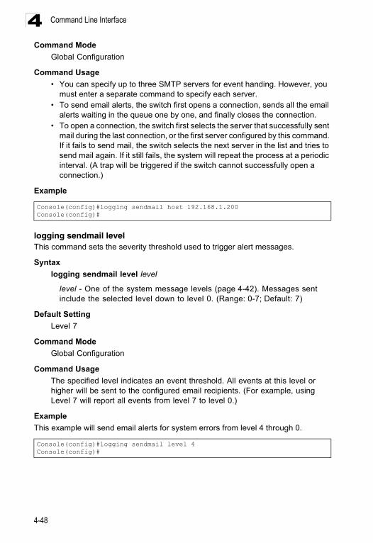
Command Line Interface4
Command ModeGlobal Configuration
Command Usage
• You can specify up to three SMTP servers for event handing. However, you must enter a separate command to specify each server.
• To send email alerts, the switch first opens a connection, sends all the email alerts waiting in the queue one by one, and finally closes the connection.
• To open a connection, the switch first selects the server that successfully sent mail during the last connection, or the first server configured by this command. If it fails to send mail, the switch selects the next server in the list and tries to send mail again. If it still fails, the system will repeat the process at a periodic interval. (A trap will be triggered if the switch cannot successfully open a connection.)
Example
logging sendmail levelThis command sets the severity threshold used to trigger alert messages.
Syntax
logging sendmail level level
level - One of the system message levels (page 4-42). Messages sent include the selected level down to level 0. (Range: 0-7; Default: 7)
Default Setting
Level 7
Command Mode
Global Configuration
Command Usage
The specified level indicates an event threshold. All events at this level or higher will be sent to the configured email recipients. (For example, using Level 7 will report all events from level 7 to level 0.)
Example
This example will send email alerts for system errors from level 4 through 0.
Console(config)#logging sendmail host 192.168.1.200Console(config)#
Console(config)#logging sendmail level 4Console(config)#
4-48
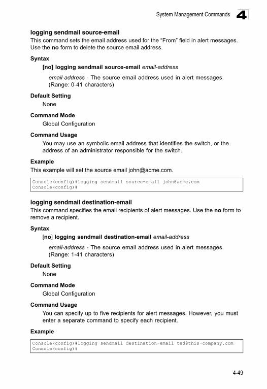
System Management Commands 4
logging sendmail source-emailThis command sets the email address used for the “From” field in alert messages. Use the no form to delete the source email address.Syntax
[no] logging sendmail source-email email-address
email-address - The source email address used in alert messages. (Range: 0-41 characters)
Default Setting
None
Command Mode
Global Configuration
Command Usage
You may use an symbolic email address that identifies the switch, or the address of an administrator responsible for the switch.
Example
This example will set the source email [email protected].
logging sendmail destination-emailThis command specifies the email recipients of alert messages. Use the no form to remove a recipient.
Syntax
[no] logging sendmail destination-email email-address
email-address - The source email address used in alert messages. (Range: 1-41 characters)
Default Setting
None
Command Mode
Global Configuration
Command Usage
You can specify up to five recipients for alert messages. However, you must enter a separate command to specify each recipient.
Example
Console(config)#logging sendmail source-email [email protected](config)#
Console(config)#logging sendmail destination-email [email protected](config)#
4-49
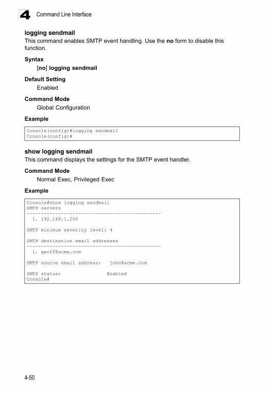
Command Line Interface4
logging sendmailThis command enables SMTP event handling. Use the no form to disable this function.Syntax
[no] logging sendmail
Default Setting
Enabled
Command Mode
Global Configuration
Example
show logging sendmailThis command displays the settings for the SMTP event handler.
Command Mode
Normal Exec, Privileged Exec
Example
Console(config)#logging sendmailConsole(config)#
Console#show logging sendmailSMTP servers----------------------------------------------- 1. 192.168.1.200
SMTP minimum severity level: 4
SMTP destination email addresses----------------------------------------------- 1. [email protected]
SMTP source email address: [email protected]
SMTP status: EnabledConsole#
4-50
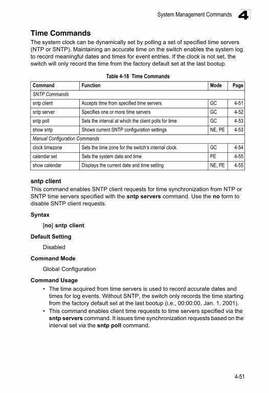
System Management Commands 4
Time CommandsThe system clock can be dynamically set by polling a set of specified time servers (NTP or SNTP). Maintaining an accurate time on the switch enables the system log to record meaningful dates and times for event entries. If the clock is not set, the switch will only record the time from the factory default set at the last bootup.sntp clientThis command enables SNTP client requests for time synchronization from NTP or SNTP time servers specified with the sntp servers command. Use the no form to disable SNTP client requests.
Syntax
[no] sntp client
Default Setting
Disabled
Command Mode
Global Configuration
Command Usage
• The time acquired from time servers is used to record accurate dates and times for log events. Without SNTP, the switch only records the time starting from the factory default set at the last bootup (i.e., 00:00:00, Jan. 1, 2001).
• This command enables client time requests to time servers specified via the sntp servers command. It issues time synchronization requests based on the interval set via the sntp poll command.
Table 4-18 Time Commands
Command Function Mode Page
SNTP Commands
sntp client Accepts time from specified time servers GC 4-51
sntp server Specifies one or more time servers GC 4-52
sntp poll Sets the interval at which the client polls for time GC 4-53
show sntp Shows current SNTP configuration settings NE, PE 4-53
Manual Configuration Commands
clock timezone Sets the time zone for the switch’s internal clock GC 4-54
calendar set Sets the system date and time PE 4-55
show calendar Displays the current date and time setting NE, PE 4-55
4-51
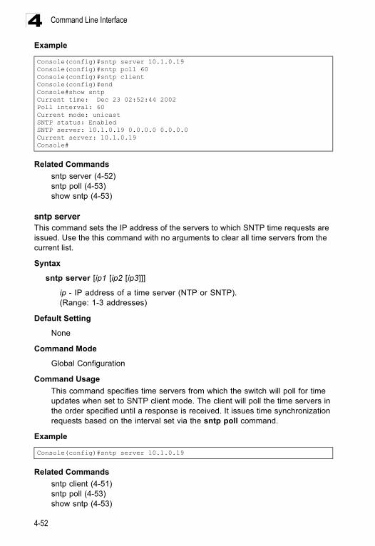
Command Line Interface4
ExampleRelated Commands
sntp server (4-52)sntp poll (4-53)show sntp (4-53)
sntp serverThis command sets the IP address of the servers to which SNTP time requests are issued. Use the this command with no arguments to clear all time servers from the current list.
Syntax
sntp server [ip1 [ip2 [ip3]]]
ip - IP address of a time server (NTP or SNTP). (Range: 1-3 addresses)
Default Setting
None
Command Mode
Global Configuration
Command Usage
This command specifies time servers from which the switch will poll for time updates when set to SNTP client mode. The client will poll the time servers in the order specified until a response is received. It issues time synchronization requests based on the interval set via the sntp poll command.
Example
Related Commands
sntp client (4-51)sntp poll (4-53)show sntp (4-53)
Console(config)#sntp server 10.1.0.19Console(config)#sntp poll 60Console(config)#sntp clientConsole(config)#endConsole#show sntpCurrent time: Dec 23 02:52:44 2002Poll interval: 60Current mode: unicastSNTP status: EnabledSNTP server: 10.1.0.19 0.0.0.0 0.0.0.0Current server: 10.1.0.19Console#
Console(config)#sntp server 10.1.0.19
4-52
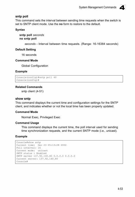
System Management Commands 4
sntp pollThis command sets the interval between sending time requests when the switch is set to SNTP client mode. Use the no form to restore to the default.Syntax
sntp poll secondsno sntp poll
seconds - Interval between time requests. (Range: 16-16384 seconds)
Default Setting
16 seconds
Command Mode
Global Configuration
Example
Related Commands
sntp client (4-51)
show sntpThis command displays the current time and configuration settings for the SNTP client, and indicates whether or not the local time has been properly updated.
Command Mode
Normal Exec, Privileged Exec
Command Usage
This command displays the current time, the poll interval used for sending time synchronization requests, and the current SNTP mode (i.e., unicast).
Example
Console(config)#sntp poll 60Console(config)#
Console#show sntpCurrent time: Dec 23 05:13:28 2002Poll interval: 16Current mode: unicastSNTP status : EnabledSNTP server 137.92.140.80 0.0.0.0 0.0.0.0Current server: 137.92.140.80Console#
4-53
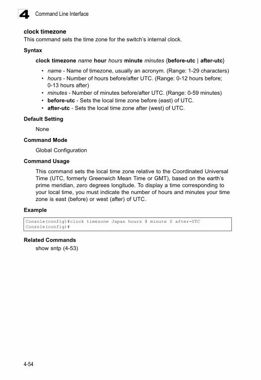
Command Line Interface4
clock timezoneThis command sets the time zone for the switch’s internal clock.Syntax
clock timezone name hour hours minute minutes {before-utc | after-utc}
• name - Name of timezone, usually an acronym. (Range: 1-29 characters)• hours - Number of hours before/after UTC. (Range: 0-12 hours before;
0-13 hours after)• minutes - Number of minutes before/after UTC. (Range: 0-59 minutes)• before-utc - Sets the local time zone before (east) of UTC.• after-utc - Sets the local time zone after (west) of UTC.
Default Setting
None
Command Mode
Global Configuration
Command Usage
This command sets the local time zone relative to the Coordinated Universal Time (UTC, formerly Greenwich Mean Time or GMT), based on the earth’s prime meridian, zero degrees longitude. To display a time corresponding to your local time, you must indicate the number of hours and minutes your time zone is east (before) or west (after) of UTC.
Example
Related Commands
show sntp (4-53)
Console(config)#clock timezone Japan hours 8 minute 0 after-UTCConsole(config)#
4-54
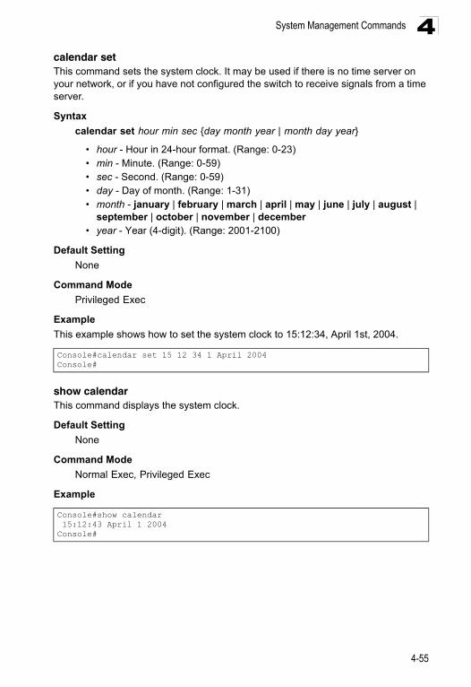
System Management Commands 4
calendar setThis command sets the system clock. It may be used if there is no time server on your network, or if you have not configured the switch to receive signals from a time server.Syntax
calendar set hour min sec {day month year | month day year}
• hour - Hour in 24-hour format. (Range: 0-23)• min - Minute. (Range: 0-59)• sec - Second. (Range: 0-59)• day - Day of month. (Range: 1-31)• month - january | february | march | april | may | june | july | august |
september | october | november | december • year - Year (4-digit). (Range: 2001-2100)
Default Setting
None
Command Mode
Privileged Exec
Example
This example shows how to set the system clock to 15:12:34, April 1st, 2004.
show calendarThis command displays the system clock.
Default Setting
None
Command Mode
Normal Exec, Privileged Exec
Example
Console#calendar set 15 12 34 1 April 2004Console#
Console#show calendar 15:12:43 April 1 2004Console#
4-55
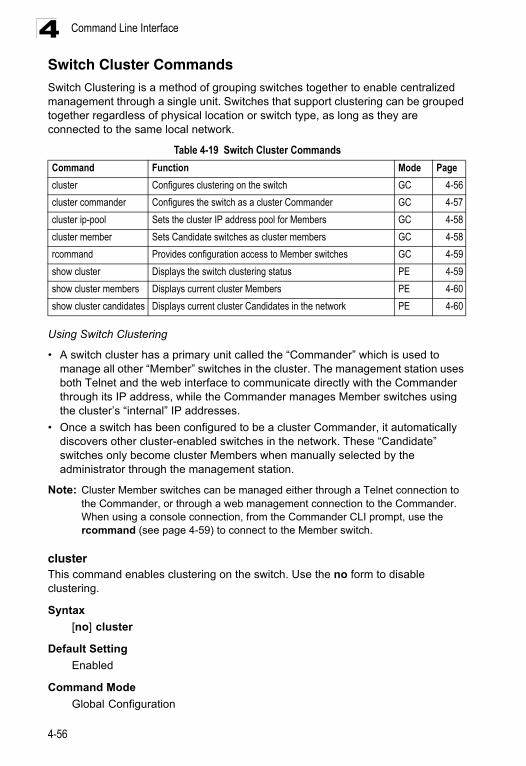
Command Line Interface4
Switch Cluster CommandsSwitch Clustering is a method of grouping switches together to enable centralized management through a single unit. Switches that support clustering can be grouped together regardless of physical location or switch type, as long as they are connected to the same local network.Using Switch Clustering
• A switch cluster has a primary unit called the “Commander” which is used to manage all other “Member” switches in the cluster. The management station uses both Telnet and the web interface to communicate directly with the Commander through its IP address, while the Commander manages Member switches using the cluster’s “internal” IP addresses.
• Once a switch has been configured to be a cluster Commander, it automatically discovers other cluster-enabled switches in the network. These “Candidate” switches only become cluster Members when manually selected by the administrator through the management station.
Note: Cluster Member switches can be managed either through a Telnet connection to the Commander, or through a web management connection to the Commander. When using a console connection, from the Commander CLI prompt, use the rcommand (see page 4-59) to connect to the Member switch.
clusterThis command enables clustering on the switch. Use the no form to disable clustering.
Syntax
[no] cluster
Default Setting
Enabled
Command Mode
Global Configuration
Table 4-19 Switch Cluster Commands
Command Function Mode Page
cluster Configures clustering on the switch GC 4-56
cluster commander Configures the switch as a cluster Commander GC 4-57
cluster ip-pool Sets the cluster IP address pool for Members GC 4-58
cluster member Sets Candidate switches as cluster members GC 4-58
rcommand Provides configuration access to Member switches GC 4-59
show cluster Displays the switch clustering status PE 4-59
show cluster members Displays current cluster Members PE 4-60
show cluster candidates Displays current cluster Candidates in the network PE 4-60
4-56
System Management Commands 4
Command Usage• To create a switch cluster, first be sure that clustering is enabled on the switch (the default is enabled), then set the switch as a Cluster Commander. Set a Cluster IP Pool that does not conflict with any other IP subnets in the network. Cluster IP addresses are assigned to switches when they become Members and are used for communication between Member switches and the Commander.
• Switch clusters are limited to the same Ethernet broadcast domain.• There can be up to 100 candidates and 16 member switches in one cluster. • A switch can only be a Member of one cluster.• Configured switch clusters are maintained across power resets and network
changes.
Example
cluster commanderThis command enables the switch as a cluster Commander. Use the no form to disable the switch as cluster Commander.
Syntax
[no] cluster commander
Default Setting
Disabled
Command Mode
Global Configuration
Command Usage
• Once a switch has been configured to be a cluster Commander, it automatically discovers other cluster-enabled switches in the network. These “Candidate” switches only become cluster Members when manually selected by the administrator through the management station.
• Cluster Member switches can be managed through only using a Telnet connection to the Commander. From the Commander CLI prompt, use the rcommand id command to connect to the Member switch.
Example
Console(config)#clusterConsole(config)#
Console(config)#cluster commanderConsole(config)#
4-57
Command Line Interface4
cluster ip-poolThis command sets the cluster IP address pool. Use the no form to reset to the default address.Syntax
cluster ip-pool ip-addressno cluster ip-pool
ip-address - The base IP address for IP addresses assigned to cluster Members. The IP address must start 10.x.x.x.
Default Setting
10.254.254.1
Command Mode
Global Configuration
Command Usage
• An “internal” IP address pool is used to assign IP addresses to Member switches in the cluster. Internal cluster IP addresses are in the form 10.x.x.member-ID. Only the base IP address of the pool needs to be set since Member IDs can only be between 1 and 16.
• Set a Cluster IP Pool that does not conflict with addresses in the network IP subnet. Cluster IP addresses are assigned to switches when they become Members and are used for communication between Member switches and the Commander.
• You cannot change the cluster IP pool when the switch is currently in Commander mode. Commander mode must first be disabled.
Example
cluster memberThis command configures a Candidate switch as a cluster Member. Use the no form to remove a Member switch from the cluster.
Syntax
cluster member mac-address mac-address id member-idno cluster member id member-id
• mac-address - The MAC address of the Candidate switch.• member-id - The ID number to assign to the Member switch. (Range: 1-16)
Default Setting
No Members
Command Mode
Global Configuration
Console(config)#cluster ip-pool 10.2.3.4Console(config)#
4-58
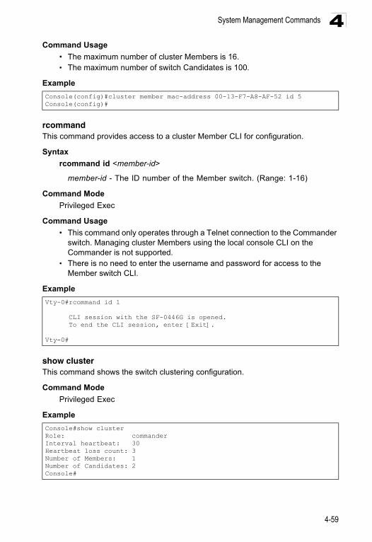
System Management Commands 4
Command Usage• The maximum number of cluster Members is 16.• The maximum number of switch Candidates is 100.
Example
rcommandThis command provides access to a cluster Member CLI for configuration.
Syntax
rcommand id <member-id>
member-id - The ID number of the Member switch. (Range: 1-16)
Command Mode
Privileged Exec
Command Usage
• This command only operates through a Telnet connection to the Commander switch. Managing cluster Members using the local console CLI on the Commander is not supported.
• There is no need to enter the username and password for access to the Member switch CLI.
Example
show clusterThis command shows the switch clustering configuration.
Command Mode
Privileged Exec
Example
Console(config)#cluster member mac-address 00-13-F7-A8-AF-52 id 5Console(config)#
Vty-0#rcommand id 1
CLI session with the SF-0446G is opened. To end the CLI session, enter [Exit].
Vty-0#
Console#show clusterRole: commanderInterval heartbeat: 30Heartbeat loss count: 3Number of Members: 1Number of Candidates: 2Console#
4-59
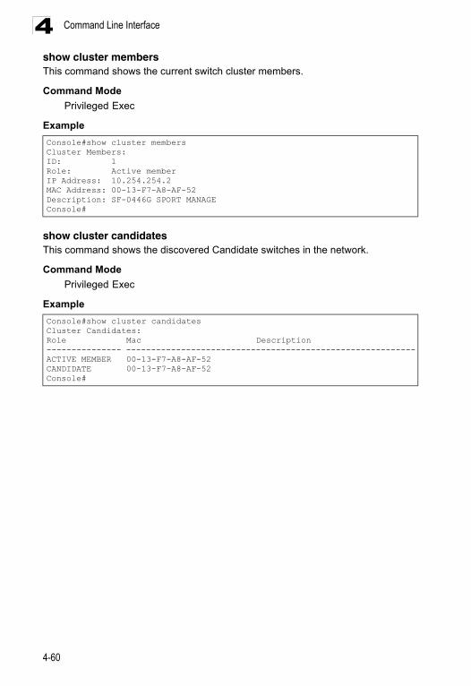
Command Line Interface4
show cluster membersThis command shows the current switch cluster members.Command Mode
Privileged Exec
Example
show cluster candidatesThis command shows the discovered Candidate switches in the network.
Command Mode
Privileged Exec
Example
Console#show cluster membersCluster Members:ID: 1Role: Active memberIP Address: 10.254.254.2MAC Address: 00-13-F7-A8-AF-52Description: SF-0446G SPORT MANAGEConsole#
Console#show cluster candidatesCluster Candidates:Role Mac Description--------------- ----------------------------------------------------------ACTIVE MEMBER 00-13-F7-A8-AF-52 CANDIDATE 00-13-F7-A8-AF-52 Console#
4-60
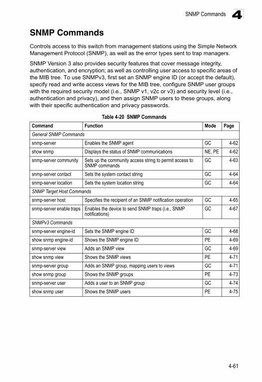
SNMP Commands 4
SNMP CommandsControls access to this switch from management stations using the Simple Network Management Protocol (SNMP), as well as the error types sent to trap managers.SNMP Version 3 also provides security features that cover message integrity, authentication, and encryption; as well as controlling user access to specific areas of the MIB tree. To use SNMPv3, first set an SNMP engine ID (or accept the default), specify read and write access views for the MIB tree, configure SNMP user groups with the required security model (i.e., SNMP v1, v2c or v3) and security level (i.e., authentication and privacy), and then assign SNMP users to these groups, along with their specific authentication and privacy passwords.
Table 4-20 SNMP Commands
Command Function Mode Page
General SNMP Commands
snmp-server Enables the SNMP agent GC 4-62
show snmp Displays the status of SNMP communications NE, PE 4-62
snmp-server community Sets up the community access string to permit access to SNMP commands
GC 4-63
snmp-server contact Sets the system contact string GC 4-64
snmp-server location Sets the system location string GC 4-64
SNMP Target Host Commands
snmp-server host Specifies the recipient of an SNMP notification operation GC 4-65
snmp-server enable traps Enables the device to send SNMP traps (i.e., SNMP notifications)
GC 4-67
SNMPv3 Commands
snmp-server engine-id Sets the SNMP engine ID GC 4-68
show snmp engine-id Shows the SNMP engine ID PE 4-69
snmp-server view Adds an SNMP view GC 4-69
show snmp view Shows the SNMP views PE 4-71
snmp-server group Adds an SNMP group, mapping users to views GC 4-71
show snmp group Shows the SNMP groups PE 4-73
snmp-server user Adds a user to an SNMP group GC 4-74
show snmp user Shows the SNMP users PE 4-75
4-61
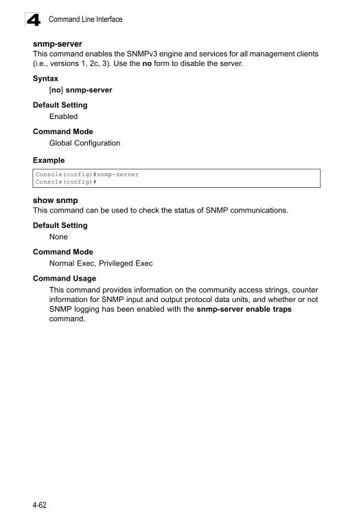
Command Line Interface4
snmp-serverThis command enables the SNMPv3 engine and services for all management clients (i.e., versions 1, 2c, 3). Use the no form to disable the server.Syntax
[no] snmp-server
Default Setting
Enabled
Command Mode
Global Configuration
Example
show snmpThis command can be used to check the status of SNMP communications.
Default Setting
None
Command Mode
Normal Exec, Privileged Exec
Command Usage
This command provides information on the community access strings, counter information for SNMP input and output protocol data units, and whether or not SNMP logging has been enabled with the snmp-server enable traps command.
Console(config)#snmp-serverConsole(config)#
4-62
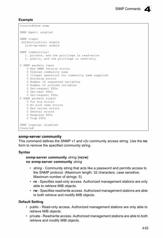
SNMP Commands 4
Examplesnmp-server communityThis command defines the SNMP v1 and v2c community access string. Use the no form to remove the specified community string.
Syntax
snmp-server community string [ro|rw]no snmp-server community string
• string - Community string that acts like a password and permits access to the SNMP protocol. (Maximum length: 32 characters, case sensitive; Maximum number of strings: 5)
• ro - Specifies read-only access. Authorized management stations are only able to retrieve MIB objects.
• rw - Specifies read/write access. Authorized management stations are able to both retrieve and modify MIB objects.
Default Setting
• public - Read-only access. Authorized management stations are only able to retrieve MIB objects.
• private - Read/write access. Authorized management stations are able to both retrieve and modify MIB objects.
Console#show snmp
SNMP Agent: enabled
SNMP traps: Authentication: enable Link-up-down: enable
SNMP communities: 1. private, and the privilege is read-write 2. public, and the privilege is read-only
0 SNMP packets input 0 Bad SNMP version errors 0 Unknown community name 0 Illegal operation for community name supplied 0 Encoding errors 0 Number of requested variables 0 Number of altered variables 0 Get-request PDUs 0 Get-next PDUs 0 Set-request PDUs0 SNMP packets output 0 Too big errors 0 No such name errors 0 Bad values errors 0 General errors 0 Response PDUs 0 Trap PDUs
SNMP logging: disabledConsole#
4-63
Command Line Interface4
Command ModeGlobal Configuration
Example
snmp-server contactThis command sets the system contact string. Use the no form to remove the system contact information.
Syntax
snmp-server contact stringno snmp-server contact
string - String that describes the system contact information. (Maximum length: 255 characters)
Default Setting
None
Command Mode
Global Configuration
Example
Related Commands
snmp-server location (4-64)
snmp-server locationThis command sets the system location string. Use the no form to remove the location string.
Syntax
snmp-server location textno snmp-server location
text - String that describes the system location. (Maximum length: 255 characters)
Default Setting
None
Command Mode
Global Configuration
Console(config)#snmp-server community alpha rwConsole(config)#
Console(config)#snmp-server contact PaulConsole(config)#
4-64
SNMP Commands 4
ExampleRelated Commands
snmp-server contact (4-64)
snmp-server host This command specifies the recipient of a Simple Network Management Protocol notification operation. Use the no form to remove the specified host.
Syntax
snmp-server host host-addr [inform [retry retries | timeout seconds]] community-string [version {1 | 2c | 3 {auth | noauth | priv} [udp-port port]}
no snmp-server host host-addr
• host-addr - Internet address of the host (the targeted recipient). (Maximum host addresses: 5 trap destination IP address entries)
• inform - Notifications are sent as inform messages. Note that this option is only available for version 2c and 3 hosts. (Default: traps are used)- retries - The maximum number of times to resend an inform message if
the recipient does not acknowledge receipt. (Range: 0-255; Default: 3)- seconds - The number of seconds to wait for an acknowledgment before
resending an inform message. (Range: 0-2147483647 centiseconds; Default: 1500 centiseconds)
• community-string - Password-like community string sent with the notification operation to SNMP V1 and V2c hosts. Although you can set this string using the snmp-server host command by itself, we recommend that you define this string using the snmp-server community command prior to using the snmp-server host command. (Maximum length: 32 characters)
• version - Specifies whether to send notifications as SNMP Version 1, 2c or 3 traps. (Range: 1, 2c, 3; Default: 1)- auth | noauth | priv - This group uses SNMPv3 with authentication, no
authentication, or with authentication and privacy. See "Simple Network Management Protocol" on page 3-35 for further information about these authentication and encryption options.
• port - Host UDP port to use. (Range: 1-65535; Default: 162)
Default Setting
• Host Address: None• Notification Type: Traps• SNMP Version: 1• UDP Port: 162
Command Mode
Global Configuration
Console(config)#snmp-server location WC-19Console(config)#
4-65
Command Line Interface4
Command Usage• If you do not enter an snmp-server host command, no notifications are sent. In order to configure the switch to send SNMP notifications, you must enter at least one snmp-server host command. In order to enable multiple hosts, you must issue a separate snmp-server host command for each host.
• The snmp-server host command is used in conjunction with the snmp-server enable traps command. Use the snmp-server enable traps command to enable the sending of traps or informs and to specify which SNMP notifications are sent globally. For a host to receive notifications, at least one snmp-server enable traps command and the snmp-server host command for that host must be enabled.
• Some notification types cannot be controlled with the snmp-server enable traps command. For example, some notification types are always enabled.
• Notifications are issued by the switch as trap messages by default. The recipient of a trap message does not send a response to the switch. Traps are therefore not as reliable as inform messages, which include a request for acknowledgement of receipt. Informs can be used to ensure that critical information is received by the host. However, note that informs consume more system resources because they must be kept in memory until a response is received. Informs also add to network traffic. You should consider these effects when deciding whether to issue notifications as traps or informs.
To send an inform to a SNMPv2c host, complete these steps:1. Enable the SNMP agent (page 4-62).2. Allow the switch to send SNMP traps; i.e., notifications (page 4-67).3. Specify the target host that will receive inform messages with the
snmp-server host command as described in this section.4. Create a view with the required notification messages (page 4-69).5. Create a group that includes the required notify view (page 4-71).
To send an inform to a SNMPv3 host, complete these steps:1. Enable the SNMP agent (page 4-62).2. Allow the switch to send SNMP traps; i.e., notifications (page 4-67).3. Specify the target host that will receive inform messages with the
snmp-server host command as described in this section.4. Create a view with the required notification messages (page 4-69).5. Create a group that includes the required notify view (page 4-71).6. Specify a remote engine ID where the user resides (page 4-68).7. Then configure a remote user (page 4-74).
• The switch can send SNMP Version 1, 2c or 3 notifications to a host IP address, depending on the SNMP version that the management station supports. If the snmp-server host command does not specify the SNMP version, the default is to send SNMP version 1 notifications.
• If you specify an SNMP Version 3 host, then the community string is interpreted as an SNMP user name. If you use the V3 “auth” or “priv” options, the user name must first be defined with the snmp-server user command. Otherwise, the authentication password and/or privacy password will not
4-66
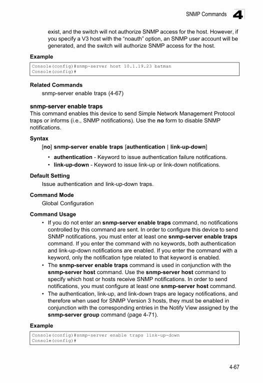
SNMP Commands 4
exist, and the switch will not authorize SNMP access for the host. However, if you specify a V3 host with the “noauth” option, an SNMP user account will be generated, and the switch will authorize SNMP access for the host.Example
Related Commands
snmp-server enable traps (4-67)
snmp-server enable trapsThis command enables this device to send Simple Network Management Protocol traps or informs (i.e., SNMP notifications). Use the no form to disable SNMP notifications.
Syntax
[no] snmp-server enable traps [authentication | link-up-down]
• authentication - Keyword to issue authentication failure notifications. • link-up-down - Keyword to issue link-up or link-down notifications.
Default Setting
Issue authentication and link-up-down traps.
Command Mode
Global Configuration
Command Usage
• If you do not enter an snmp-server enable traps command, no notifications controlled by this command are sent. In order to configure this device to send SNMP notifications, you must enter at least one snmp-server enable traps command. If you enter the command with no keywords, both authentication and link-up-down notifications are enabled. If you enter the command with a keyword, only the notification type related to that keyword is enabled.
• The snmp-server enable traps command is used in conjunction with the snmp-server host command. Use the snmp-server host command to specify which host or hosts receive SNMP notifications. In order to send notifications, you must configure at least one snmp-server host command.
• The authentication, link-up, and link-down traps are legacy notifications, and therefore when used for SNMP Version 3 hosts, they must be enabled in conjunction with the corresponding entries in the Notify View assigned by the snmp-server group command (page 4-71).
Example
Console(config)#snmp-server host 10.1.19.23 batmanConsole(config)#
Console(config)#snmp-server enable traps link-up-downConsole(config)#
4-67
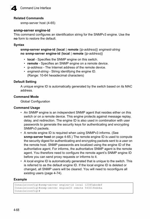
Command Line Interface4
Related Commandssnmp-server host (4-65)
snmp-server engine-idThis command configures an identification string for the SNMPv3 engine. Use the no form to restore the default.
Syntax
snmp-server engine-id {local | remote {ip-address}} engineid-stringno snmp-server engine-id {local | remote {ip-address}}
• local - Specifies the SNMP engine on this switch.• remote - Specifies an SNMP engine on a remote device.• ip-address - The Internet address of the remote device.• engineid-string - String identifying the engine ID.
(Range: 10-64 hexadecimal characters)
Default Setting
A unique engine ID is automatically generated by the switch based on its MAC address.
Command Mode
Global Configuration
Command Usage
• An SNMP engine is an independent SNMP agent that resides either on this switch or on a remote device. This engine protects against message replay, delay, and redirection. The engine ID is also used in combination with user passwords to generate the security keys for authenticating and encrypting SNMPv3 packets.
• A remote engine ID is required when using SNMPv3 informs. (See snmp-server host on page 4-65.) The remote engine ID is used to compute the security digest for authenticating and encrypting packets sent to a user on the remote host. SNMP passwords are localized using the engine ID of the authoritative agent. For informs, the authoritative SNMP agent is the remote agent. You therefore need to configure the remote agent’s SNMP engine ID before you can send proxy requests or informs to it.
• A local engine ID is automatically generated that is unique to the switch. This is referred to as the default engine ID. If the local engine ID is deleted or changed, all SNMP users will be cleared. You will need to reconfigure all existing users (page 4-74).
Example
Console(config)#snmp-server engine-id local 12345abcdefConsole(config)#snmp-server engineID remote 54321fedcbaConsole(config)#
4-68
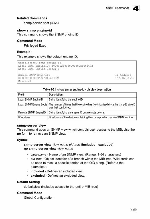
SNMP Commands 4
Related Commandssnmp-server host (4-65)
show snmp engine-idThis command shows the SNMP engine ID.
Command Mode
Privileged Exec
Example
This example shows the default engine ID.
snmp-server viewThis command adds an SNMP view which controls user access to the MIB. Use the no form to remove an SNMP view.
Syntax
snmp-server view view-name oid-tree {included | excluded}no snmp-server view view-name
• view-name - Name of an SNMP view. (Range: 1-64 characters)• oid-tree - Object identifier of a branch within the MIB tree. Wild cards can
be used to mask a specific portion of the OID string. (Refer to the examples.)
• included - Defines an included view.• excluded - Defines an excluded view.
Default Setting
defaultview (includes access to the entire MIB tree)
Command Mode
Global Configuration
Console#show snmp engine-idLocal SNMP EngineID: 8000002a8000000000e8666672Local SNMP Engine Boots: 1
Remote SNMP EngineID IP Address80000000030004e2b316c54321 192.168.1.19Console#
Table 4-21 show snmp engine-id - display description
Field Description
Local SNMP EngineID String identifying the engine ID.
Local SNMP Engine Boots The number of times that the engine has (re-)initialized since the snmp EngineID was last configured.
Remote SNMP EngineID String identifying an engine ID on a remote device.
IP Address IP address of the device containing the corresponding remote SNMP engine.
4-69
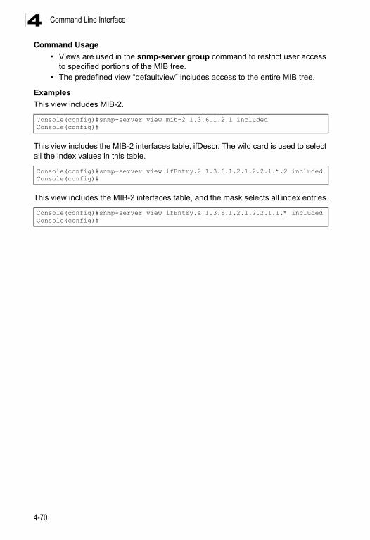
Command Line Interface4
Command Usage• Views are used in the snmp-server group command to restrict user access to specified portions of the MIB tree.
• The predefined view “defaultview” includes access to the entire MIB tree.
Examples
This view includes MIB-2.
This view includes the MIB-2 interfaces table, ifDescr. The wild card is used to select all the index values in this table.
This view includes the MIB-2 interfaces table, and the mask selects all index entries.
Console(config)#snmp-server view mib-2 1.3.6.1.2.1 includedConsole(config)#
Console(config)#snmp-server view ifEntry.2 1.3.6.1.2.1.2.2.1.*.2 includedConsole(config)#
Console(config)#snmp-server view ifEntry.a 1.3.6.1.2.1.2.2.1.1.* includedConsole(config)#
4-70
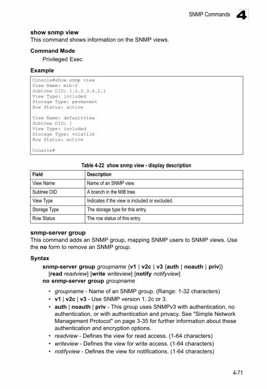
SNMP Commands 4
show snmp viewThis command shows information on the SNMP views.Command Mode
Privileged Exec
Example
snmp-server groupThis command adds an SNMP group, mapping SNMP users to SNMP views. Use the no form to remove an SNMP group.
Syntax
snmp-server group groupname {v1 | v2c | v3 {auth | noauth | priv}} [read readview] [write writeview] [notify notifyview]
no snmp-server group groupname
• groupname - Name of an SNMP group. (Range: 1-32 characters)• v1 | v2c | v3 - Use SNMP version 1, 2c or 3.• auth | noauth | priv - This group uses SNMPv3 with authentication, no
authentication, or with authentication and privacy. See "Simple Network Management Protocol" on page 3-35 for further information about these authentication and encryption options.
• readview - Defines the view for read access. (1-64 characters)• writeview - Defines the view for write access. (1-64 characters)• notifyview - Defines the view for notifications. (1-64 characters)
Console#show snmp viewView Name: mib-2Subtree OID: 1.2.2.3.6.2.1View Type: includedStorage Type: permanentRow Status: active
View Name: defaultviewSubtree OID: 1View Type: includedStorage Type: volatileRow Status: active
Console#
Table 4-22 show snmp view - display description
Field Description
View Name Name of an SNMP view.
Subtree OID A branch in the MIB tree.
View Type Indicates if the view is included or excluded.
Storage Type The storage type for this entry.
Row Status The row status of this entry.
4-71
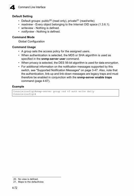
Command Line Interface4
Default Setting• Default groups: public20 (read only), private21 (read/write)• readview - Every object belonging to the Internet OID space (1.3.6.1).• writeview - Nothing is defined.• notifyview - Nothing is defined.
Command Mode
Global Configuration
Command Usage
• A group sets the access policy for the assigned users.• When authentication is selected, the MD5 or SHA algorithm is used as
specified in the snmp-server user command.• When privacy is selected, the DES 56-bit algorithm is used for data encryption.• For additional information on the notification messages supported by this
switch, see "Supported Notification Messages" on page 3-47. Also, note that the authentication, link-up and link-down messages are legacy traps and must therefore be enabled in conjunction with the snmp-server enable traps command (page 4-67).
Example
20. No view is defined.21. Maps to the defaultview.
Console(config)#snmp-server group r&d v3 auth write dailyConsole(config)#
4-72
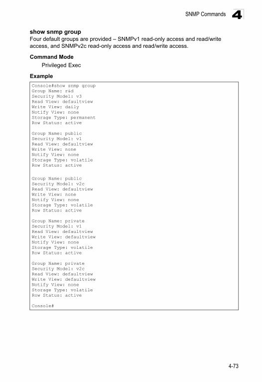
SNMP Commands 4
show snmp groupFour default groups are provided – SNMPv1 read-only access and read/write access, and SNMPv2c read-only access and read/write access.Command Mode
Privileged Exec
Example
Console#show snmp groupGroup Name: r&dSecurity Model: v3Read View: defaultviewWrite View: dailyNotify View: noneStorage Type: permanentRow Status: active
Group Name: publicSecurity Model: v1Read View: defaultviewWrite View: noneNotify View: noneStorage Type: volatileRow Status: active
Group Name: publicSecurity Model: v2cRead View: defaultviewWrite View: noneNotify View: noneStorage Type: volatileRow Status: active
Group Name: privateSecurity Model: v1Read View: defaultviewWrite View: defaultviewNotify View: noneStorage Type: volatileRow Status: active
Group Name: privateSecurity Model: v2cRead View: defaultviewWrite View: defaultviewNotify View: noneStorage Type: volatileRow Status: active
Console#
4-73
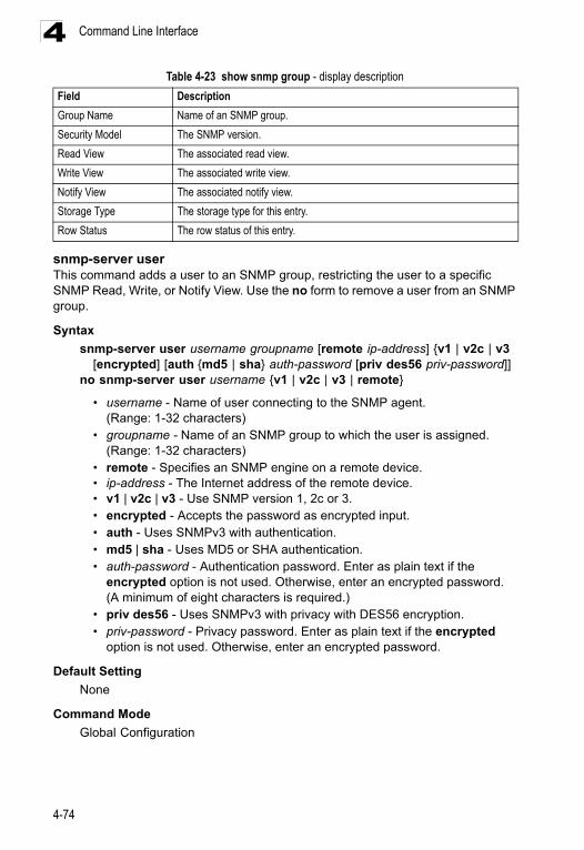
Command Line Interface4
snmp-server userThis command adds a user to an SNMP group, restricting the user to a specific SNMP Read, Write, or Notify View. Use the no form to remove a user from an SNMP group.
Syntax
snmp-server user username groupname [remote ip-address] {v1 | v2c | v3 [encrypted] [auth {md5 | sha} auth-password [priv des56 priv-password]]
no snmp-server user username {v1 | v2c | v3 | remote}
• username - Name of user connecting to the SNMP agent. (Range: 1-32 characters)
• groupname - Name of an SNMP group to which the user is assigned. (Range: 1-32 characters)
• remote - Specifies an SNMP engine on a remote device.• ip-address - The Internet address of the remote device.• v1 | v2c | v3 - Use SNMP version 1, 2c or 3.• encrypted - Accepts the password as encrypted input.• auth - Uses SNMPv3 with authentication.• md5 | sha - Uses MD5 or SHA authentication.• auth-password - Authentication password. Enter as plain text if the
encrypted option is not used. Otherwise, enter an encrypted password. (A minimum of eight characters is required.)
• priv des56 - Uses SNMPv3 with privacy with DES56 encryption.• priv-password - Privacy password. Enter as plain text if the encrypted
option is not used. Otherwise, enter an encrypted password.
Default Setting
None
Command Mode
Global Configuration
Table 4-23 show snmp group - display description
Field Description
Group Name Name of an SNMP group.
Security Model The SNMP version.
Read View The associated read view.
Write View The associated write view.
Notify View The associated notify view.
Storage Type The storage type for this entry.
Row Status The row status of this entry.
4-74
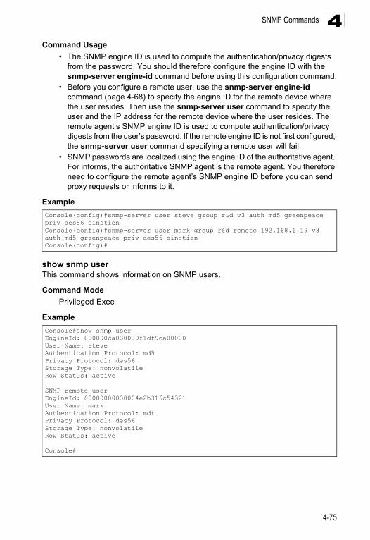
SNMP Commands 4
Command Usage• The SNMP engine ID is used to compute the authentication/privacy digests from the password. You should therefore configure the engine ID with the snmp-server engine-id command before using this configuration command.
• Before you configure a remote user, use the snmp-server engine-id command (page 4-68) to specify the engine ID for the remote device where the user resides. Then use the snmp-server user command to specify the user and the IP address for the remote device where the user resides. The remote agent’s SNMP engine ID is used to compute authentication/privacy digests from the user’s password. If the remote engine ID is not first configured, the snmp-server user command specifying a remote user will fail.
• SNMP passwords are localized using the engine ID of the authoritative agent. For informs, the authoritative SNMP agent is the remote agent. You therefore need to configure the remote agent’s SNMP engine ID before you can send proxy requests or informs to it.
Example
show snmp userThis command shows information on SNMP users.
Command Mode
Privileged Exec
Example
Console(config)#snmp-server user steve group r&d v3 auth md5 greenpeace priv des56 einstienConsole(config)#snmp-server user mark group r&d remote 192.168.1.19 v3 auth md5 greenpeace priv des56 einstienConsole(config)#
Console#show snmp userEngineId: 800000ca030030f1df9ca00000User Name: steveAuthentication Protocol: md5Privacy Protocol: des56Storage Type: nonvolatileRow Status: active
SNMP remote userEngineId: 80000000030004e2b316c54321User Name: markAuthentication Protocol: mdtPrivacy Protocol: des56Storage Type: nonvolatileRow Status: active
Console#
4-75
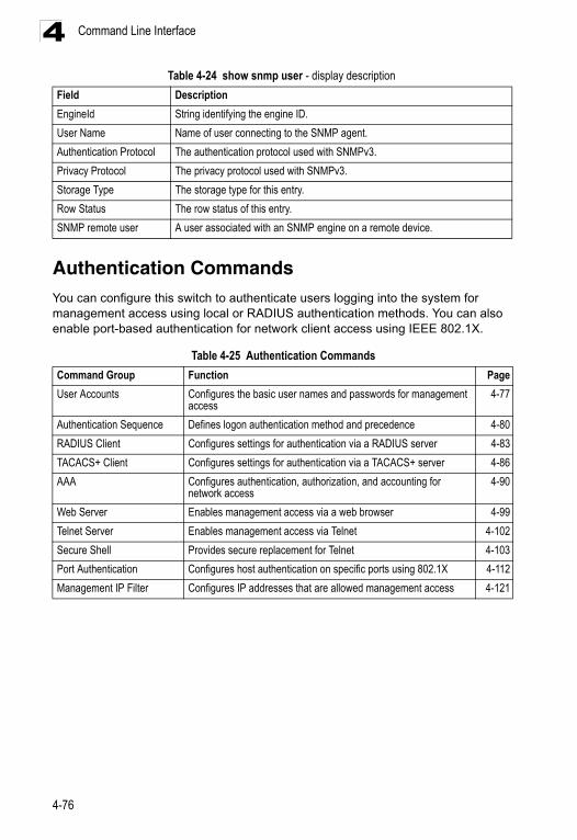
Command Line Interface4
Authentication Commands You can configure this switch to authenticate users logging into the system for management access using local or RADIUS authentication methods. You can also enable port-based authentication for network client access using IEEE 802.1X.
Table 4-24 show snmp user - display description
Field Description
EngineId String identifying the engine ID.
User Name Name of user connecting to the SNMP agent.
Authentication Protocol The authentication protocol used with SNMPv3.
Privacy Protocol The privacy protocol used with SNMPv3.
Storage Type The storage type for this entry.
Row Status The row status of this entry.
SNMP remote user A user associated with an SNMP engine on a remote device.
Table 4-25 Authentication Commands
Command Group Function Page
User Accounts Configures the basic user names and passwords for management access
4-77
Authentication Sequence Defines logon authentication method and precedence 4-80
RADIUS Client Configures settings for authentication via a RADIUS server 4-83
TACACS+ Client Configures settings for authentication via a TACACS+ server 4-86
AAA Configures authentication, authorization, and accounting for network access
4-90
Web Server Enables management access via a web browser 4-99
Telnet Server Enables management access via Telnet 4-102
Secure Shell Provides secure replacement for Telnet 4-103
Port Authentication Configures host authentication on specific ports using 802.1X 4-112
Management IP Filter Configures IP addresses that are allowed management access 4-121
4-76
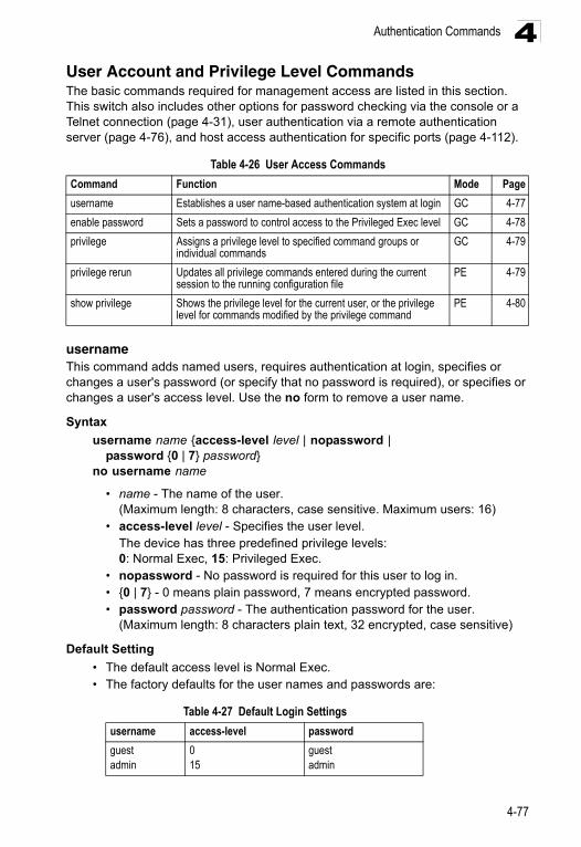
Authentication Commands 4
User Account and Privilege Level CommandsThe basic commands required for management access are listed in this section. This switch also includes other options for password checking via the console or a Telnet connection (page 4-31), user authentication via a remote authentication server (page 4-76), and host access authentication for specific ports (page 4-112).usernameThis command adds named users, requires authentication at login, specifies or changes a user's password (or specify that no password is required), or specifies or changes a user's access level. Use the no form to remove a user name.
Syntax
username name {access-level level | nopassword | password {0 | 7} password}
no username name
• name - The name of the user. (Maximum length: 8 characters, case sensitive. Maximum users: 16)
• access-level level - Specifies the user level.The device has three predefined privilege levels: 0: Normal Exec, 15: Privileged Exec.
• nopassword - No password is required for this user to log in. • {0 | 7} - 0 means plain password, 7 means encrypted password. • password password - The authentication password for the user.
(Maximum length: 8 characters plain text, 32 encrypted, case sensitive)
Default Setting
• The default access level is Normal Exec. • The factory defaults for the user names and passwords are:
Table 4-26 User Access Commands
Command Function Mode Page
username Establishes a user name-based authentication system at login GC 4-77
enable password Sets a password to control access to the Privileged Exec level GC 4-78
privilege Assigns a privilege level to specified command groups or individual commands
GC 4-79
privilege rerun Updates all privilege commands entered during the current session to the running configuration file
PE 4-79
show privilege Shows the privilege level for the current user, or the privilege level for commands modified by the privilege command
PE 4-80
Table 4-27 Default Login Settings
username access-level password
guestadmin
0 15
guestadmin
4-77
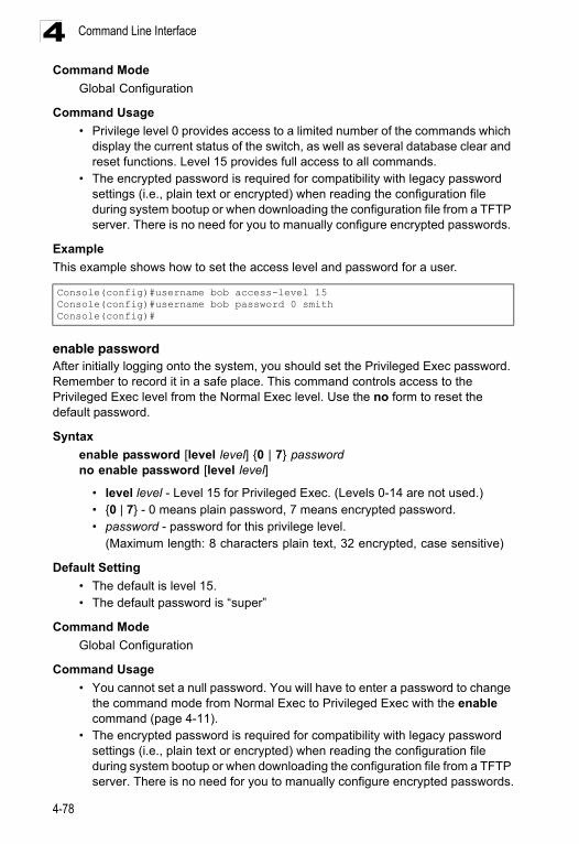
Command Line Interface4
Command ModeGlobal Configuration
Command Usage
• Privilege level 0 provides access to a limited number of the commands which display the current status of the switch, as well as several database clear and reset functions. Level 15 provides full access to all commands.
• The encrypted password is required for compatibility with legacy password settings (i.e., plain text or encrypted) when reading the configuration file during system bootup or when downloading the configuration file from a TFTP server. There is no need for you to manually configure encrypted passwords.
Example
This example shows how to set the access level and password for a user.
enable passwordAfter initially logging onto the system, you should set the Privileged Exec password. Remember to record it in a safe place. This command controls access to the Privileged Exec level from the Normal Exec level. Use the no form to reset the default password.
Syntax
enable password [level level] {0 | 7} passwordno enable password [level level]
• level level - Level 15 for Privileged Exec. (Levels 0-14 are not used.)• {0 | 7} - 0 means plain password, 7 means encrypted password. • password - password for this privilege level.
(Maximum length: 8 characters plain text, 32 encrypted, case sensitive)
Default Setting
• The default is level 15. • The default password is “super”
Command Mode
Global Configuration
Command Usage
• You cannot set a null password. You will have to enter a password to change the command mode from Normal Exec to Privileged Exec with the enable command (page 4-11).
• The encrypted password is required for compatibility with legacy password settings (i.e., plain text or encrypted) when reading the configuration file during system bootup or when downloading the configuration file from a TFTP server. There is no need for you to manually configure encrypted passwords.
Console(config)#username bob access-level 15Console(config)#username bob password 0 smithConsole(config)#
4-78
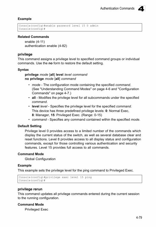
Authentication Commands 4
ExampleRelated Commands
enable (4-11)authentication enable (4-82)
privilegeThis command assigns a privilege level to specified command groups or individual commands. Use the no form to restore the default setting.
Syntax
privilege mode [all] level level commandno privilege mode [all] command
• mode - The configuration mode containing the specified command. (See "Understanding Command Modes" on page 4-6 and "Configuration Commands" on page 4-7.)
• all - Modifies the privilege level for all subcommands under the specified command.
• level level - Specifies the privilege level for the specified command.This device has three predefined privilege levels: 0: Normal Exec, 8: Manager, 15: Privileged Exec. (Range: 0-15)
• command - Specifies any command contained within the specified mode.
Default Setting
Privilege level 0 provides access to a limited number of the commands which display the current status of the switch, as well as several database clear and reset functions. Level 8 provides access to all display status and configuration commands, except for those controlling various authentication and security features. Level 15 provides full access to all commands.
Command Mode
Global Configuration
Example
This example sets the privilege level for the ping command to Privileged Exec.
privilege rerunThis command updates all privilege commands entered during the current session to the running configuration.
Command Mode
Privileged Exec
Console(config)#enable password level 15 0 adminConsole(config)#
Console(config)#privilege exec level 15 pingConsole(config)#
4-79
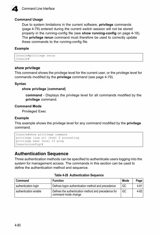
Command Line Interface4
Command UsageDue to system limitations in the current software, privilege commands (page 4-79) entered during the current switch session will not be stored properly in the running-config file (see show running-config on page 4-18). The privilege rerun command must therefore be used to correctly update these commands to the running-config file.
Example
show privilegeThis command shows the privilege level for the current user, or the privilege level for commands modified by the privilege command (see page 4-79).
Syntax
show privilege [command]
command - Displays the privilege level for all commands modified by the privilege command.
Command Mode
Privileged Exec
Example
This example shows the privilege level for any command modified by the privilege command.
Authentication SequenceThree authentication methods can be specified to authenticate users logging into the system for management access. The commands in this section can be used to define the authentication method and sequence.
Console#privilege rerunConsole#
Console#show privilege commandprivilege line all level 0 accountingprivilege exec level 15 pingConsole(config)#
Table 4-28 Authentication Sequence
Command Function Mode Page
authentication login Defines logon authentication method and precedence GC 4-81
authentication enable Defines the authentication method and precedence for command mode change
GC 4-82
4-80
Authentication Commands 4
authentication loginThis command defines the login authentication method and precedence. Use the no form to restore the default.Syntax
authentication login {[local] [radius] [tacacs]}no authentication login
• local - Use local password. • radius - Use RADIUS server password. • tacacs - Use TACACS server password.
Default Setting
Local
Command Mode
Global Configuration
Command Usage
• RADIUS uses UDP while TACACS+ uses TCP. UDP only offers best effort delivery, while TCP offers a connection-oriented transport. Also, note that RADIUS encrypts only the password in the access-request packet from the client to the server, while TACACS+ encrypts the entire body of the packet.
• RADIUS and TACACS+ logon authentication assigns a specific privilege level for each user name and password pair. The user name, password, and privilege level must be configured on the authentication server.
• You can specify three authentication methods in a single command to indicate the authentication sequence. For example, if you enter “authentication login radius tacacs local,” the user name and password on the RADIUS server is verified first. If the RADIUS server is not available, then authentication is attempted on the TACACS+ server. If the TACACS+ server is not available, the local user name and password is checked.
Example
Related Commands
username - for setting the local user names and passwords (4-77)
Console(config)#authentication login radiusConsole(config)#
4-81
Command Line Interface4
authentication enableThis command defines the authentication method and precedence to use when changing from Exec command mode to Privileged Exec command mode with the enable command (see page 4-11). Use the no form to restore the default.Syntax
authentication enable {[local] [radius] [tacacs]}no authentication enable
• local - Use local password only. • radius - Use RADIUS server password only. • tacacs - Use TACACS server password.
Default Setting
Local
Command Mode
Global Configuration
Command Usage
• RADIUS uses UDP while TACACS+ uses TCP. UDP only offers best effort delivery, while TCP offers a connection-oriented transport. Also, note that RADIUS encrypts only the password in the access-request packet from the client to the server, while TACACS+ encrypts the entire body of the packet.
• RADIUS and TACACS+ logon authentication assigns a specific privilege level for each user name and password pair. The user name, password, and privilege level must be configured on the authentication server.
• You can specify three authentication methods in a single command to indicate the authentication sequence. For example, if you enter “authentication enable radius tacacs local,” the user name and password on the RADIUS server is verified first. If the RADIUS server is not available, then authentication is attempted on the TACACS+ server. If the TACACS+ server is not available, the local user name and password is checked.
Example
Related Commands
enable password - sets the password for changing command modes (4-78)
Console(config)#authentication enable radiusConsole(config)#
4-82
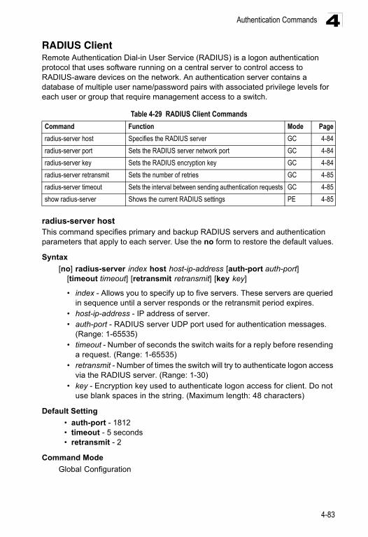
Authentication Commands 4
RADIUS ClientRemote Authentication Dial-in User Service (RADIUS) is a logon authentication protocol that uses software running on a central server to control access to RADIUS-aware devices on the network. An authentication server contains a database of multiple user name/password pairs with associated privilege levels for each user or group that require management access to a switch.radius-server hostThis command specifies primary and backup RADIUS servers and authentication parameters that apply to each server. Use the no form to restore the default values.
Syntax
[no] radius-server index host host-ip-address [auth-port auth-port] [timeout timeout] [retransmit retransmit] [key key]
• index - Allows you to specify up to five servers. These servers are queried in sequence until a server responds or the retransmit period expires.
• host-ip-address - IP address of server.• auth-port - RADIUS server UDP port used for authentication messages.
(Range: 1-65535)• timeout - Number of seconds the switch waits for a reply before resending
a request. (Range: 1-65535)• retransmit - Number of times the switch will try to authenticate logon access
via the RADIUS server. (Range: 1-30)• key - Encryption key used to authenticate logon access for client. Do not
use blank spaces in the string. (Maximum length: 48 characters)
Default Setting
• auth-port - 1812• timeout - 5 seconds• retransmit - 2
Command Mode
Global Configuration
Table 4-29 RADIUS Client Commands
Command Function Mode Page
radius-server host Specifies the RADIUS server GC 4-84
radius-server port Sets the RADIUS server network port GC 4-84
radius-server key Sets the RADIUS encryption key GC 4-84
radius-server retransmit Sets the number of retries GC 4-85
radius-server timeout Sets the interval between sending authentication requests GC 4-85
show radius-server Shows the current RADIUS settings PE 4-85
4-83
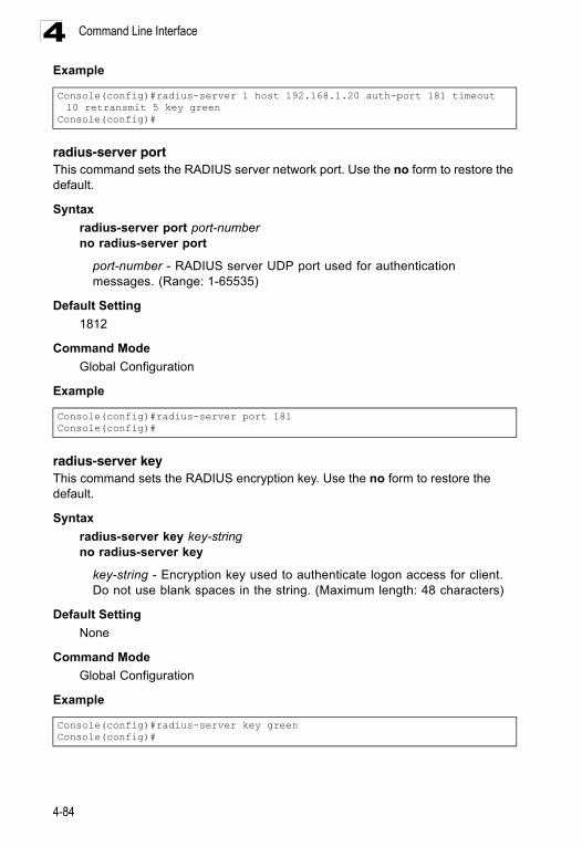
Command Line Interface4
Exampleradius-server portThis command sets the RADIUS server network port. Use the no form to restore the default.
Syntax
radius-server port port-numberno radius-server port
port-number - RADIUS server UDP port used for authentication messages. (Range: 1-65535)
Default Setting
1812
Command Mode
Global Configuration
Example
radius-server keyThis command sets the RADIUS encryption key. Use the no form to restore the default.
Syntax
radius-server key key-stringno radius-server key
key-string - Encryption key used to authenticate logon access for client. Do not use blank spaces in the string. (Maximum length: 48 characters)
Default Setting
None
Command Mode
Global Configuration
Example
Console(config)#radius-server 1 host 192.168.1.20 auth-port 181 timeout 10 retransmit 5 key green
Console(config)#
Console(config)#radius-server port 181Console(config)#
Console(config)#radius-server key greenConsole(config)#
4-84
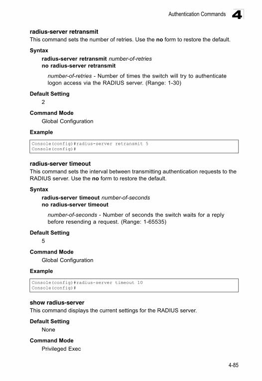
Authentication Commands 4
radius-server retransmitThis command sets the number of retries. Use the no form to restore the default.Syntax
radius-server retransmit number-of-retriesno radius-server retransmit
number-of-retries - Number of times the switch will try to authenticate logon access via the RADIUS server. (Range: 1-30)
Default Setting
2
Command Mode
Global Configuration
Example
radius-server timeoutThis command sets the interval between transmitting authentication requests to the RADIUS server. Use the no form to restore the default.
Syntax
radius-server timeout number-of-secondsno radius-server timeout
number-of-seconds - Number of seconds the switch waits for a reply before resending a request. (Range: 1-65535)
Default Setting
5
Command Mode
Global Configuration
Example
show radius-server This command displays the current settings for the RADIUS server.
Default Setting
None
Command Mode
Privileged Exec
Console(config)#radius-server retransmit 5Console(config)#
Console(config)#radius-server timeout 10Console(config)#
4-85

Command Line Interface4
ExampleTACACS+ ClientTerminal Access Controller Access Control System (TACACS+) is a logon authentication protocol that uses software running on a central server to control access to TACACS-aware devices on the network. An authentication server contains a database of multiple user name/password pairs with associated privilege levels for each user or group that require management access to a switch.
Console#show radius-server
Remote RADIUS Server Configuration: Global Settings Communication Key with RADIUS Server: Auth-Port: 1812 Retransmit Times: 2 Request Timeout: 5
Sever 1: Server IP Address: 192.168.1.1 Communication Key with RADIUS Server: Auth-Port: 1812 Retransmit Times: 2 Request Timeout: 5
Radius server group:Group Name Member Index--------------------- -------------radius 1
Console#
Table 4-30 TACACS Commands
Command Function Mode Page
tacacs-server host Specifies the TACACS+ server GC 4-87
tacacs-server port Specifies the TACACS+ server network port GC 4-87
tacacs-server key Sets the TACACS+ encryption key GC 4-88
tacacs-server retransmit Sets the number of retries GC 4-88
tacacs-server timeout Sets the interval before resending an authentication request GC 4-89
show tacacs-server Shows the current TACACS+ settings GC 4-89
4-86
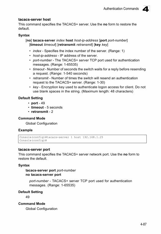
Authentication Commands 4
tacacs-server hostThis command specifies the TACACS+ server. Use the no form to restore the default.Syntax
[no] tacacs-server index host host-ip-address [port port-number] [timeout timeout] [retransmit retransmit] [key key]
• index - Specifies the index number of the server. (Range: 1)• host-ip-address - IP address of the server.• port-number - The TACACS+ server TCP port used for authentication
messages. (Range: 1-65535)• timeout - Number of seconds the switch waits for a reply before resending
a request. (Range: 1-540 seconds)• retransmit - Number of times the switch will resend an authentication
request to the TACACS+ server. (Range: 1-30)• key - Encryption key used to authenticate logon access for client. Do not
use blank spaces in the string. (Maximum length: 48 characters)
Default Setting
• port - 49• timeout - 5 seconds• retransmit - 2
Command Mode
Global Configuration
Example
tacacs-server portThis command specifies the TACACS+ server network port. Use the no form to restore the default.
Syntax
tacacs-server port port-numberno tacacs-server port
port-number - TACACS+ server TCP port used for authentication messages. (Range: 1-65535)
Default Setting
49
Command Mode
Global Configuration
Console(config)#tacacs-server 1 host 192.168.1.25Console(config)#
4-87
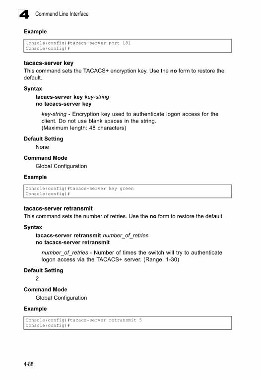
Command Line Interface4
Exampletacacs-server keyThis command sets the TACACS+ encryption key. Use the no form to restore the default.
Syntax
tacacs-server key key-stringno tacacs-server key
key-string - Encryption key used to authenticate logon access for the client. Do not use blank spaces in the string. (Maximum length: 48 characters)
Default Setting
None
Command Mode
Global Configuration
Example
tacacs-server retransmitThis command sets the number of retries. Use the no form to restore the default.
Syntax
tacacs-server retransmit number_of_retriesno tacacs-server retransmit
number_of_retries - Number of times the switch will try to authenticate logon access via the TACACS+ server. (Range: 1-30)
Default Setting
2
Command Mode
Global Configuration
Example
Console(config)#tacacs-server port 181Console(config)#
Console(config)#tacacs-server key greenConsole(config)#
Console(config)#tacacs-server retransmit 5Console(config)#
4-88
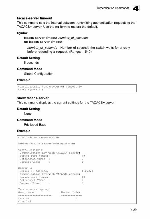
Authentication Commands 4
tacacs-server timeoutThis command sets the interval between transmitting authentication requests to the TACACS+ server. Use the no form to restore the default.Syntax
tacacs-server timeout number_of_secondsno tacacs-server timeout
number_of_seconds - Number of seconds the switch waits for a reply before resending a request. (Range: 1-540)
Default Setting
5 seconds
Command Mode
Global Configuration
Example
show tacacs-serverThis command displays the current settings for the TACACS+ server.
Default Setting
None
Command Mode
Privileged Exec
Example
Console(config)#tacacs-server timeout 10Console(config)#
Console#show tacacs-server
Remote TACACS+ server configuration:
Global Settings: Communication Key with TACACS+ Server: Server Port Number: 49 Retransmit Times : 2 Request Times : 5
Server 1: Server IP address: 1.2.3.4 Communication key with TACACS+ server: Server port number: 49 Retransmit Times : 2 Request Times : 5
Tacacs server group:Group Name Member Index--------------------- -------------tacacs+ 1Console#
4-89
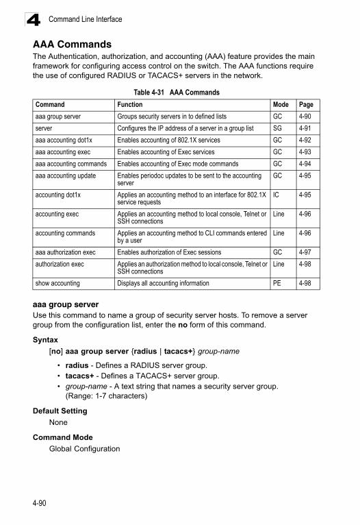
Command Line Interface4
AAA CommandsThe Authentication, authorization, and accounting (AAA) feature provides the main framework for configuring access control on the switch. The AAA functions require the use of configured RADIUS or TACACS+ servers in the network.aaa group serverUse this command to name a group of security server hosts. To remove a server group from the configuration list, enter the no form of this command.
Syntax
[no] aaa group server {radius | tacacs+} group-name
• radius - Defines a RADIUS server group.• tacacs+ - Defines a TACACS+ server group.• group-name - A text string that names a security server group.
(Range: 1-7 characters)
Default Setting
None
Command Mode
Global Configuration
Table 4-31 AAA Commands
Command Function Mode Page
aaa group server Groups security servers in to defined lists GC 4-90
server Configures the IP address of a server in a group list SG 4-91
aaa accounting dot1x Enables accounting of 802.1X services GC 4-92
aaa accounting exec Enables accounting of Exec services GC 4-93
aaa accounting commands Enables accounting of Exec mode commands GC 4-94
aaa accounting update Enables periodoc updates to be sent to the accounting server
GC 4-95
accounting dot1x Applies an accounting method to an interface for 802.1X service requests
IC 4-95
accounting exec Applies an accounting method to local console, Telnet or SSH connections
Line 4-96
accounting commands Applies an accounting method to CLI commands entered by a user
Line 4-96
aaa authorization exec Enables authorization of Exec sessions GC 4-97
authorization exec Applies an authorization method to local console, Telnet or SSH connections
Line 4-98
show accounting Displays all accounting information PE 4-98
4-90
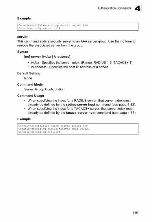
Authentication Commands 4
ExampleserverThis command adds a security server to an AAA server group. Use the no form to remove the associated server from the group.
Syntax
[no] server {index | ip-address}
• index - Specifies the server index. (Range: RADIUS 1-5, TACACS+ 1) • ip-address - Specifies the host IP address of a server.
Default Setting
None
Command Mode
Server Group Configuration
Command Usage
• When specifying the index for a RADIUS server, that server index must already be defined by the radius-server host command (see page 4-83).
• When specifying the index for a TACACS+ server, that server index must already be defined by the tacacs-server host command (see page 4-87).
Example
Console(config)#aaa group server radius tpsConsole(config-sg-radius)#
Console(config)#aaa group server radius tpsConsole(config-sg-radius)#server 10.2.68.120Console(config-sg-radius)#
4-91
Command Line Interface4
aaa accounting dot1xThis command enables the accounting of requested 802.1X services for network access. Use the no form to disable the accounting service.Syntax
aaa accounting dot1x {default | method-name} start-stop group {radius | tacacs+ |server-group}
no aaa accounting dot1x {default | method-name}
• default - Specifies the default accounting method for service requests. • method-name - Specifies an accounting method for service requests.
(Range: 1-255 characters)• start-stop - Records accounting from starting point and stopping point.• group - Specifies the server group to use.
- radius - Specifies all RADIUS hosts configure with the radius-server host command described on page 4-83.
- tacacs+ - Specifies all TACACS+ hosts configure with the tacacs-server host command described on page 4-87.
- server-group - Specifies the name of a server group configured with the aaa group server command described on 4-90. (Range: 1-255 characters)
Default Setting
Accounting is not enabledNo servers are specified
Command Mode
Global Configuration
Command Usage
Note that the default and method-name fields are only used to describe the accounting method(s) configured on the specified RADIUS or TACACS+ servers, and do not actually send any information to the servers about the methods to use.
Example
Console(config)#aaa accounting dot1x default start-stop group radiusConsole(config)#
4-92
Authentication Commands 4
aaa accounting execThis command enables the accounting of requested Exec services for network access. Use the no form to disable the accounting service.Syntax
aaa accounting exec {default | method-name} start-stop group {radius | tacacs+ |server-group}
no aaa accounting exec {default | method-name}
• default - Specifies the default accounting method for service requests. • method-name - Specifies an accounting method for service requests.
(Range: 1-255 characters)• start-stop - Records accounting from starting point and stopping point.• group - Specifies the server group to use.
- radius - Specifies all RADIUS hosts configure with the radius-server host command described on page 4-83.
- tacacs+ - Specifies all TACACS+ hosts configure with the tacacs-server host command described on page 4-87.
- server-group - Specifies the name of a server group configured with the aaa group server command described on 4-90. (Range: 1-255 characters)
Default Setting
Accounting is not enabledNo servers are specified
Command Mode
Global Configuration
Command Usage
• This command runs accounting for Exec service requests for the local console and Telnet connections.
• Note that the default and method-name fields are only used to describe the accounting method(s) configured on the specified RADIUS or TACACS+ servers, and do not actually send any information to the servers about the methods to use.
Example
Console(config)#aaa accounting exec default start-stop group tacacs+Console(config)#
4-93
Command Line Interface4
aaa accounting commandsThis command enables the accounting of Exec mode commands. Use the no form to disable the accounting service.Syntax
aaa accounting commands level {default | method-name} start-stop group {tacacs+ |server-group}
no aaa accounting commands level {default | method-name}
• level - The privilege level for executing commands. (Range: 0-15)• default - Specifies the default accounting method for service requests. • method-name - Specifies an accounting method for service requests.
(Range: 1-255 characters)• start-stop - Records accounting from starting point and stopping point.• group - Specifies the server group to use.
- tacacs+ - Specifies all TACACS+ hosts configure with the tacacs-server host command described on page 4-87.
- server-group - Specifies the name of a server group configured with the aaa group server command described on 4-90. (Range: 1-255 characters)
Default Setting
Accounting is not enabledNo servers are specified
Command Mode
Global Configuration
Command Usage
• The accounting of Exec mode commands is only supported by TACACS+ servers.
• Note that the default and method-name fields are only used to describe the accounting method(s) configured on the specified TACACS+ server, and do not actually send any information to the server about the methods to use.
Example
Console(config)#aaa accounting commands 15 default start-stop group tacacs+
Console(config)#
4-94
Authentication Commands 4
aaa accounting updateThis command enables the sending of periodic updates to the accounting server. Use the no form to disable accounting updates.Syntax
aaa accounting update [periodic interval]no aaa accounting update
interval - Sends an interim accounting record to the server at this interval. (Range: 1-2147483647 minutes)
Default Setting
1 minute
Command Mode
Global Configuration
Command Usage
• When accounting updates are enabled, the switch issues periodic interim accounting records for all users on the system.
• Using the command without specifying an interim interval enables updates, but does not change the current interval setting.
Example
accounting dot1xThis command applies an accounting method for 802.1X service requests on an interface. Use the no form to disable accounting on the interface.
Syntax
accounting dot1x {default | list-name}no accounting dot1x
• default - Specifies the default method list created with the aaa accounting dot1x command (page 4-92).
• list-name - Specifies a method list created with the aaa accounting dot1x command.
Default Setting
None
Command Mode
Interface Configuration
Console(config)#aaa accounting update periodic 30Console(config)#
4-95
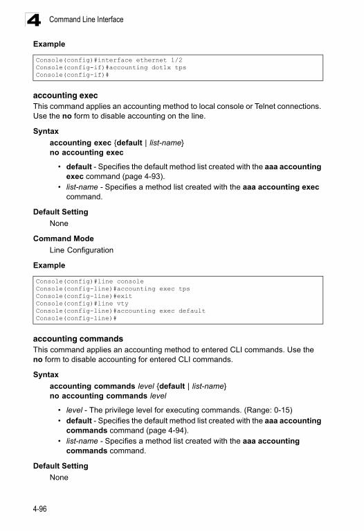
Command Line Interface4
Exampleaccounting execThis command applies an accounting method to local console or Telnet connections. Use the no form to disable accounting on the line.
Syntax
accounting exec {default | list-name}no accounting exec
• default - Specifies the default method list created with the aaa accounting exec command (page 4-93).
• list-name - Specifies a method list created with the aaa accounting exec command.
Default Setting
None
Command Mode
Line Configuration
Example
accounting commandsThis command applies an accounting method to entered CLI commands. Use the no form to disable accounting for entered CLI commands.
Syntax
accounting commands level {default | list-name}no accounting commands level
• level - The privilege level for executing commands. (Range: 0-15)• default - Specifies the default method list created with the aaa accounting
commands command (page 4-94).• list-name - Specifies a method list created with the aaa accounting
commands command.
Default Setting
None
Console(config)#interface ethernet 1/2Console(config-if)#accounting dot1x tpsConsole(config-if)#
Console(config)#line consoleConsole(config-line)#accounting exec tpsConsole(config-line)#exitConsole(config)#line vtyConsole(config-line)#accounting exec defaultConsole(config-line)#
4-96
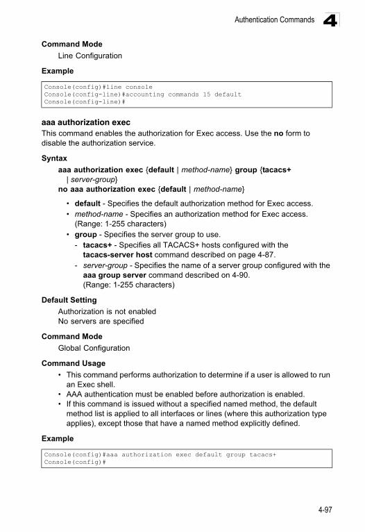
Authentication Commands 4
Command ModeLine Configuration
Example
aaa authorization execThis command enables the authorization for Exec access. Use the no form to disable the authorization service.
Syntax
aaa authorization exec {default | method-name} group {tacacs+ | server-group}
no aaa authorization exec {default | method-name}
• default - Specifies the default authorization method for Exec access. • method-name - Specifies an authorization method for Exec access.
(Range: 1-255 characters)• group - Specifies the server group to use.
- tacacs+ - Specifies all TACACS+ hosts configured with the tacacs-server host command described on page 4-87.
- server-group - Specifies the name of a server group configured with the aaa group server command described on 4-90. (Range: 1-255 characters)
Default Setting
Authorization is not enabledNo servers are specified
Command Mode
Global Configuration
Command Usage
• This command performs authorization to determine if a user is allowed to run an Exec shell.
• AAA authentication must be enabled before authorization is enabled.• If this command is issued without a specified named method, the default
method list is applied to all interfaces or lines (where this authorization type applies), except those that have a named method explicitly defined.
Example
Console(config)#line consoleConsole(config-line)#accounting commands 15 defaultConsole(config-line)#
Console(config)#aaa authorization exec default group tacacs+Console(config)#
4-97
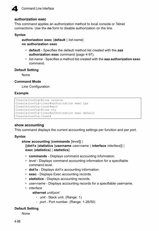
Command Line Interface4
authorization execThis command applies an authorization method to local console or Telnet connections. Use the no form to disable authorization on the line.Syntax
authorization exec {default | list-name}no authorization exec
• default - Specifies the default method list created with the aaa authorization exec command (page 4-97).
• list-name - Specifies a method list created with the aaa authorization exec command.
Default Setting
None
Command Mode
Line Configuration
Example
show accountingThis command displays the current accounting settings per function and per port.
Syntax
show accounting [commands [level]] | [[dot1x [statistics [username user-name | interface interface]] | exec [statistics] | statistics]
• commands - Displays command accounting information.• level - Displays command accounting information for a specifiable
command level.• dot1x - Displays dot1x accounting information.• exec - Displays Exec accounting records.• statistics - Displays accounting records.• user-name - Displays accounting records for a specifiable username.• interface
ethernet unit/port- unit - Stack unit. (Range: 1) - port - Port number. (Range: 1-26/50)
Default Setting
None
Console(config)#line consoleConsole(config-line)#authorization exec tpsConsole(config-line)#exitConsole(config)#line vtyConsole(config-line)#authorization exec defaultConsole(config-line)#
4-98
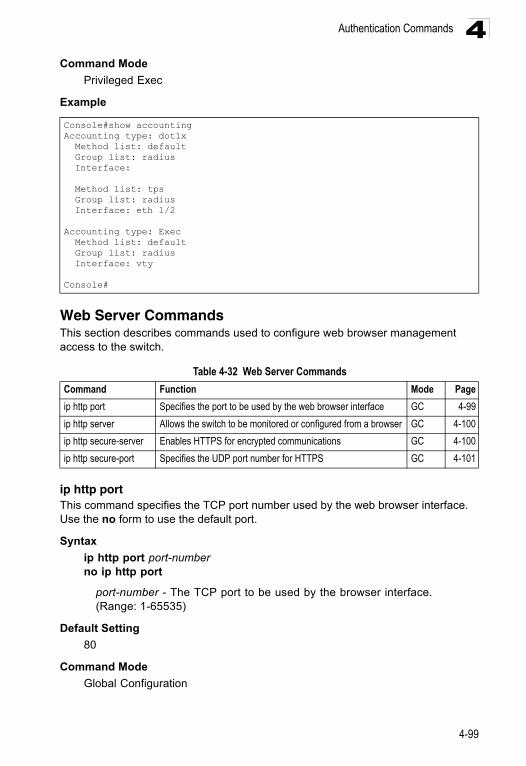
Authentication Commands 4
Command ModePrivileged Exec
Example
Web Server CommandsThis section describes commands used to configure web browser management access to the switch.
ip http portThis command specifies the TCP port number used by the web browser interface. Use the no form to use the default port.
Syntax
ip http port port-numberno ip http port
port-number - The TCP port to be used by the browser interface. (Range: 1-65535)
Default Setting
80
Command Mode
Global Configuration
Console#show accountingAccounting type: dot1x Method list: default Group list: radius Interface:
Method list: tps Group list: radius Interface: eth 1/2
Accounting type: Exec Method list: default Group list: radius Interface: vty
Console#
Table 4-32 Web Server Commands
Command Function Mode Page
ip http port Specifies the port to be used by the web browser interface GC 4-99
ip http server Allows the switch to be monitored or configured from a browser GC 4-100
ip http secure-server Enables HTTPS for encrypted communications GC 4-100
ip http secure-port Specifies the UDP port number for HTTPS GC 4-101
4-99
Command Line Interface4
ExampleRelated Commands
ip http server (4-100)
ip http serverThis command allows this device to be monitored or configured from a browser. Use the no form to disable this function.
Syntax
[no] ip http server
Default Setting
Enabled
Command Mode
Global Configuration
Example
Related Commands
ip http port (4-99)
ip http secure-serverThis command enables the secure hypertext transfer protocol (HTTPS) over the Secure Socket Layer (SSL), providing secure access (i.e., an encrypted connection) to the switch’s web interface. Use the no form to disable this function.
Syntax
[no] ip http secure-server
Default Setting
Enabled
Command Mode
Global Configuration
Command Usage
• Both HTTP and HTTPS service can be enabled independently on the switch. However, you cannot configure the HTTP and HTTPS servers to use the same UDP port.
• If you enable HTTPS, you must indicate this in the URL that you specify in your browser: https://device[:port_number]
Console(config)#ip http port 769Console(config)#
Console(config)#ip http serverConsole(config)#
4-100
Authentication Commands 4
• When you start HTTPS, the connection is established in this way:- The client authenticates the server using the server’s digital certificate.- The client and server negotiate a set of security protocols to use for the
connection.- The client and server generate session keys for encrypting and decrypting
data.• The client and server establish a secure encrypted connection.
A padlock icon should appear in the status bar for Internet Explorer 5.x or above, Netscape 6.2 or above, and Mozilla Firefox 2.0.0.0 or above.
• To specify a secure-site certificate, see “Replacing the Default Secure-site Certificate” on page 3-59. Also refer to the copy command on page 4-25.
Example
Related Commands
ip http secure-port (4-101)copy tftp https-certificate (4-25)
ip http secure-portThis command specifies the UDP port number used for HTTPS connection to the switch’s web interface. Use the no form to restore the default port.
Syntax
ip http secure-port port_numberno ip http secure-port
port_number – The UDP port used for HTTPS. (Range: 1-65535)
Default Setting
443
Command Mode
Global Configuration
Command Usage
• You cannot configure the HTTP and HTTPS servers to use the same port. • If you change the HTTPS port number, clients attempting to connect to the
HTTPS server must specify the port number in the URL, in this format:https://device:port_number
Example
Console(config)#ip http secure-serverConsole(config)#
Console(config)#ip http secure-port 1000Console(config)#
4-101
Command Line Interface4
Related Commandsip http secure-server (4-100)
Telnet Server CommandsThis section describes commands used to configure Telnet management access to the switch.
ip telnet serverThis command allows this device to be monitored or configured from Telnet. It also specifies the TCP port number used by the Telnet interface. Use the no form without the “port” keyword to disable this function. Use the no from with the “port” keyword to use the default port.
Syntax
ip telnet server [port port-number]no telnet server [port]
• port - The TCP port used by the Telnet interface.• port-number - The TCP port number to be used by the browser interface.
(Range: 1-65535)
Default Setting
• Server: Enabled• Server Port: 23
Command Mode
Global Configuration
Example
Secure Shell CommandsThis section describes the commands used to configure the SSH server. However, note that you also need to install a SSH client on the management station when using this protocol to configure the switch.
Table 4-33 Telnet Server Commands
Command Function Mode Page
ip telnet server Allows the switch to be monitored or configured from Telnet; also specifies the port to be used by the Telnet interface
GC 4-100
Console(config)#ip telnet server Console(config)#ip telnet server port 123Console(config)#
4-102
Authentication Commands 4
Note: The switch supports both SSH Version 1.5 and 2.0.Configuration Guidelines
The SSH server on this switch supports both password and public key authentication. If password authentication is specified by the SSH client, then the password can be authenticated either locally or via a RADIUS or TACACS+ remote authentication server, as specified by the authentication login command on page 4-81. If public key authentication is specified by the client, then you must configure authentication keys on both the client and the switch as described in the following section. Note that regardless of whether you use public key or password authentication, you still have to generate authentication keys on the switch and enable the SSH server.
To use the SSH server, complete these steps:
1. Generate a Host Key Pair – Use the ip ssh crypto host-key generate command to create a host public/private key pair.
2. Provide Host Public Key to Clients – Many SSH client programs automatically import the host public key during the initial connection setup with the switch. Otherwise, you need to manually create a known hosts file on the management station and place the host public key in it. An entry for a public key in the known hosts file would appear similar to the following example:
10.1.0.54 1024 35 15684995401867669259333946775054617325313674890836547254 15020245593199868544358361651999923329781766065830956 10825913212890233
Table 4-34 SSH Commands
Command Function Mode Page
ip ssh server Enables the SSH server on the switch GC 4-105
ip ssh timeout Specifies the authentication timeout for the SSH server GC 4-106
ip ssh authentication-retries
Specifies the number of retries allowed by a client GC 4-106
ip ssh server-key size Sets the SSH server key size GC 4-107
copy tftp public-key Copies the user’s public key from a TFTP server to the switch PE 4-25
delete public-key Deletes the public key for the specified user PE 4-107
ip ssh crypto host-key generate
Generates the host key PE 4-108
ip ssh crypto zeroize Clear the host key from RAM PE 4-108
ip ssh save host-key Saves the host key from RAM to flash memory PE 4-109
disconnect Terminates a line connection PE 4-39
show ip ssh Displays the status of the SSH server and the configured values for authentication timeout and retries
PE 4-109
show ssh Displays the status of current SSH sessions PE 4-110
show public-key Shows the public key for the specified user or for the host PE 4-111
show users Shows SSH users, including privilege level and public key type PE 4-21
4-103
Command Line Interface4
76546801726272571413428762941301196195566782 59566410486957427888146206 51941746772984865468615717739390164779355942303577413098022737087794545240839717526463580581767167095748047761173. Import Client’s Public Key to the Switch – Use the copy tftp public-key command to copy a file containing the public key for all the SSH client’s granted management access to the switch. (Note that these clients must be configured locally on the switch with the username command as described on page 4-77.) The clients are subsequently authenticated using these keys. The current firmware only accepts public key files based on standard UNIX format as shown in the following example for an RSA Version 1 key:
1024 35 1341081685609893921040944920155425347631641921872958921143173880 05553616163105177594083868631109291232226828519254374603100937187721199696317813662774141689851320491172048303392543241016379975923714490119380060902539484084827178194372288402533115952134861022902978982721353267131629432532818915045306393916643 [email protected]
4. Set the Optional Parameters – Set other optional parameters, including the authentication timeout, the number of retries, and the server key size.
5. Enable SSH Service – Use the ip ssh server command to enable the SSH server on the switch.
6. Authentication – One of the following authentication methods is employed:
Password Authentication (for SSH v1.5 or V2 Clients)
a) The client sends its password to the server.b) The switch compares the client's password to those stored in memory. c) If a match is found, the connection is allowed.
Note: To use SSH with only password authentication, the host public key must still be given to the client, either during initial connection or manually entered into the known host file. However, you do not need to configure the client’s keys.
Public Key Authentication – When an SSH client attempts to contact the switch, the SSH server uses the host key pair to negotiate a session key and encryption method. Only clients that have a private key corresponding to the public keys stored on the switch can access it. The following exchanges take place during this process:
Authenticating SSH v1.5 Clients
a) The client sends its RSA public key to the switch. b) The switch compares the client's public key to those stored in memory. c) If a match is found, the switch uses its secret key to generate a random
256-bit string as a challenge, encrypts this string with the user’s public key, and sends it to the client.
d) The client uses its private key to decrypt the challenge string, computes the MD5 checksum, and sends the checksum back to the switch.
e) The switch compares the checksum sent from the client against that computed for the original string it sent. If the two checksums match, this means that the client's private key corresponds to an authorized public key,
4-104
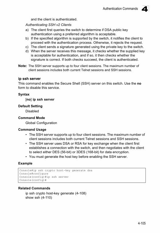
Authentication Commands 4
and the client is authenticated.Authenticating SSH v2 Clients
a) The client first queries the switch to determine if DSA public key authentication using a preferred algorithm is acceptable.
b) If the specified algorithm is supported by the switch, it notifies the client to proceed with the authentication process. Otherwise, it rejects the request.
c) The client sends a signature generated using the private key to the switch.d) When the server receives this message, it checks whether the supplied key
is acceptable for authentication, and if so, it then checks whether the signature is correct. If both checks succeed, the client is authenticated.
Note: The SSH server supports up to four client sessions. The maximum number of client sessions includes both current Telnet sessions and SSH sessions.
ip ssh serverThis command enables the Secure Shell (SSH) server on this switch. Use the no form to disable this service.
Syntax
[no] ip ssh server
Default Setting
Disabled
Command Mode
Global Configuration
Command Usage
• The SSH server supports up to four client sessions. The maximum number of client sessions includes both current Telnet sessions and SSH sessions.
• The SSH server uses DSA or RSA for key exchange when the client first establishes a connection with the switch, and then negotiates with the client to select either DES (56-bit) or 3DES (168-bit) for data encryption.
• You must generate the host key before enabling the SSH server.
Example
Related Commands
ip ssh crypto host-key generate (4-108)show ssh (4-110)
Console#ip ssh crypto host-key generate dsaConsole#configureConsole(config)#ip ssh serverConsole(config)#
4-105
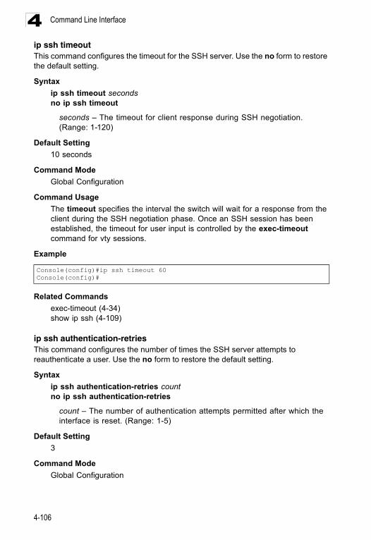
Command Line Interface4
ip ssh timeoutThis command configures the timeout for the SSH server. Use the no form to restore the default setting.Syntax
ip ssh timeout secondsno ip ssh timeout
seconds – The timeout for client response during SSH negotiation. (Range: 1-120)
Default Setting
10 seconds
Command Mode
Global Configuration
Command Usage
The timeout specifies the interval the switch will wait for a response from the client during the SSH negotiation phase. Once an SSH session has been established, the timeout for user input is controlled by the exec-timeout command for vty sessions.
Example
Related Commands
exec-timeout (4-34)show ip ssh (4-109)
ip ssh authentication-retriesThis command configures the number of times the SSH server attempts to reauthenticate a user. Use the no form to restore the default setting.
Syntax
ip ssh authentication-retries countno ip ssh authentication-retries
count – The number of authentication attempts permitted after which the interface is reset. (Range: 1-5)
Default Setting
3
Command Mode
Global Configuration
Console(config)#ip ssh timeout 60Console(config)#
4-106
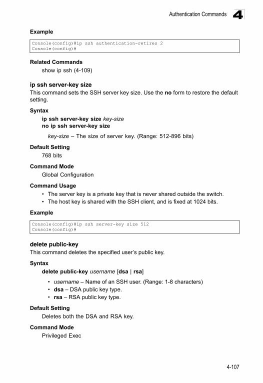
Authentication Commands 4
ExampleRelated Commands
show ip ssh (4-109)
ip ssh server-key sizeThis command sets the SSH server key size. Use the no form to restore the default setting.
Syntax
ip ssh server-key size key-sizeno ip ssh server-key size
key-size – The size of server key. (Range: 512-896 bits)
Default Setting
768 bits
Command Mode
Global Configuration
Command Usage
• The server key is a private key that is never shared outside the switch. • The host key is shared with the SSH client, and is fixed at 1024 bits.
Example
delete public-keyThis command deletes the specified user’s public key.
Syntax
delete public-key username [dsa | rsa]
• username – Name of an SSH user. (Range: 1-8 characters)• dsa – DSA public key type. • rsa – RSA public key type.
Default Setting
Deletes both the DSA and RSA key.
Command Mode
Privileged Exec
Console(config)#ip ssh authentication-retires 2Console(config)#
Console(config)#ip ssh server-key size 512Console(config)#
4-107
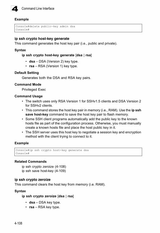
Command Line Interface4
Exampleip ssh crypto host-key generateThis command generates the host key pair (i.e., public and private).
Syntax
ip ssh crypto host-key generate [dsa | rsa]
• dsa – DSA (Version 2) key type. • rsa – RSA (Version 1) key type.
Default Setting
Generates both the DSA and RSA key pairs.
Command Mode
Privileged Exec
Command Usage
• The switch uses only RSA Version 1 for SSHv1.5 clients and DSA Version 2 for SSHv2 clients.
• This command stores the host key pair in memory (i.e., RAM). Use the ip ssh save host-key command to save the host key pair to flash memory.
• Some SSH client programs automatically add the public key to the known hosts file as part of the configuration process. Otherwise, you must manually create a known hosts file and place the host public key in it.
• The SSH server uses this host key to negotiate a session key and encryption method with the client trying to connect to it.
Example
Related Commands
ip ssh crypto zeroize (4-108)ip ssh save host-key (4-109)
ip ssh crypto zeroizeThis command clears the host key from memory (i.e. RAM).
Syntax
ip ssh crypto zeroize [dsa | rsa]
• dsa – DSA key type. • rsa – RSA key type.
Console#delete public-key admin dsaConsole#
Console#ip ssh crypto host-key generate dsaConsole#
4-108
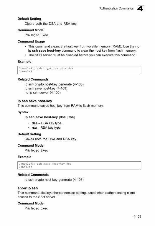
Authentication Commands 4
Default SettingClears both the DSA and RSA key.
Command Mode
Privileged Exec
Command Usage
• This command clears the host key from volatile memory (RAM). Use the no ip ssh save host-key command to clear the host key from flash memory.
• The SSH server must be disabled before you can execute this command.
Example
Related Commands
ip ssh crypto host-key generate (4-108)ip ssh save host-key (4-109)no ip ssh server (4-105)
ip ssh save host-keyThis command saves host key from RAM to flash memory.
Syntax
ip ssh save host-key [dsa | rsa]
• dsa – DSA key type. • rsa – RSA key type.
Default Setting
Saves both the DSA and RSA key.
Command Mode
Privileged Exec
Example
Related Commands
ip ssh crypto host-key generate (4-108)
show ip sshThis command displays the connection settings used when authenticating client access to the SSH server.
Command Mode
Privileged Exec
Console#ip ssh crypto zeroize dsaConsole#
Console#ip ssh save host-key dsaConsole#
4-109
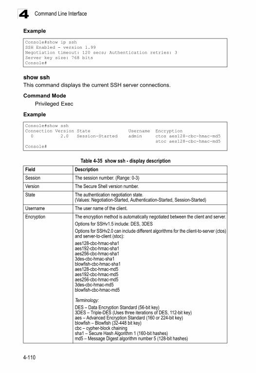
Command Line Interface4
Exampleshow sshThis command displays the current SSH server connections.
Command Mode
Privileged Exec
Example
Console#show ip sshSSH Enabled - version 1.99Negotiation timeout: 120 secs; Authentication retries: 3Server key size: 768 bitsConsole#
Console#show sshConnection Version State Username Encryption 0 2.0 Session-Started admin ctos aes128-cbc-hmac-md5 stoc aes128-cbc-hmac-md5Console#
Table 4-35 show ssh - display description
Field Description
Session The session number. (Range: 0-3)
Version The Secure Shell version number.
State The authentication negotiation state. (Values: Negotiation-Started, Authentication-Started, Session-Started)
Username The user name of the client.
Encryption The encryption method is automatically negotiated between the client and server. Options for SSHv1.5 include: DES, 3DESOptions for SSHv2.0 can include different algorithms for the client-to-server (ctos) and server-to-client (stoc):aes128-cbc-hmac-sha1aes192-cbc-hmac-sha1aes256-cbc-hmac-sha13des-cbc-hmac-sha1blowfish-cbc-hmac-sha1aes128-cbc-hmac-md5aes192-cbc-hmac-md5aes256-cbc-hmac-md53des-cbc-hmac-md5blowfish-cbc-hmac-md5
Terminology:DES – Data Encryption Standard (56-bit key)3DES – Triple-DES (Uses three iterations of DES, 112-bit key)aes – Advanced Encryption Standard (160 or 224-bit key)blowfish – Blowfish (32-448 bit key)cbc – cypher-block chainingsha1 – Secure Hash Algorithm 1 (160-bit hashes)md5 – Message Digest algorithm number 5 (128-bit hashes)
4-110
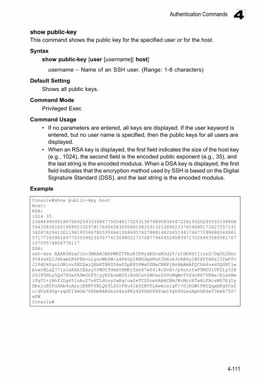
Authentication Commands 4
show public-keyThis command shows the public key for the specified user or for the host.Syntax
show public-key [user [username]| host]
username – Name of an SSH user. (Range: 1-8 characters)
Default Setting
Shows all public keys.
Command Mode
Privileged Exec
Command Usage
• If no parameters are entered, all keys are displayed. If the user keyword is entered, but no user name is specified, then the public keys for all users are displayed.
• When an RSA key is displayed, the first field indicates the size of the host key (e.g., 1024), the second field is the encoded public exponent (e.g., 35), and the last string is the encoded modulus. When a DSA key is displayed, the first field indicates that the encryption method used by SSH is based on the Digital Signature Standard (DSS), and the last string is the encoded modulus.
Example
Console#show public-key hostHost:RSA:1024 35 156849954018676692593339467750546173253136748908365472541502024559319986854435836165199992332978176606583095861082591321289023376546801726272571413428762941301196195566782595664104869574278881462065194174677298486546861571773939016477935594230357741309802273708779454524083971752646358058176716709574804776117DSA:ssh-dss AAAB3NzaC1kc3MAAACBAPWKZTPbsRIB8ydEXcxM3dyV/yrDbKStIlnzD/Dg0h2Hxc YV44sXZ2JXhamLK6P8bvuiyacWbUW/a4PAtp1KMSdqsKeh3hKoA3vRRSy1N2XFfAKxl5fwFfv JlPdOkFgzLGMinvSNYQwiQXbKTBH0Z4mUZpE85PWxDZMaCNBPjBrRAAAAFQChb4vsdfQGNIjwbvwrNLaQ77isiwAAAIEAsy5YWDC99ebYHNRj5kh47wY4i8cZvH+/p9cnrfwFTMU01VFDly3IR 2G395NLy5Qd7ZDxfA9mCOfT/yyEfbobMJZi8oGCstSNOxrZZVnMqWrTYfdrKX7YKBw/Kjw6Bm iFq7O+jAhf1Dg45loAc27s6TLdtny1wRq/ow2eTCD5nekAAACBAJ8rMccXTxHLFAczWS7EjOy DbsloBfPuSAb4oAsyjKXKVYNLQkTLZfcFRu41bS2KV5LAwecsigF/+DjKGWtPNIQqabKgYCw2 o/dVzX4Gg+yqdTlYmGA7fHGm8ARGeiG4ssFKy4Z6DmYPXFum1Yg0fhLwuHpOSKdxT3kk475S7 w0WConsole#
4-111
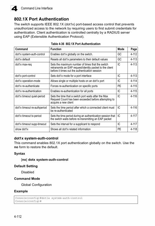
Command Line Interface4
802.1X Port AuthenticationThe switch supports IEEE 802.1X (dot1x) port-based access control that prevents unauthorized access to the network by requiring users to first submit credentials for authentication. Client authentication is controlled centrally by a RADIUS server using EAP (Extensible Authentication Protocol).dot1x system-auth-controlThis command enables 802.1X port authentication globally on the switch. Use the no form to restore the default.
Syntax
[no] dotx system-auth-control
Default Setting
Disabled
Command Mode
Global Configuration
Example
Table 4-36 802.1X Port Authentication
Command Function Mode Page
dot1x system-auth-control Enables dot1x globally on the switch. GC 4-112
dot1x default Resets all dot1x parameters to their default values GC 4-113
dot1x max-req Sets the maximum number of times that the switch retransmits an EAP request/identity packet to the client before it times out the authentication session
IC 4-113
dot1x port-control Sets dot1x mode for a port interface IC 4-113
dot1x operation-mode Allows single or multiple hosts on an dot1x port IC 4-114
dot1x re-authenticate Forces re-authentication on specific ports PE 4-115
dot1x re-authentication Enables re-authentication for all ports IC 4-115
dot1x timeout quiet-period Sets the time that a switch port waits after the Max Request Count has been exceeded before attempting to acquire a new client
IC 4-116
dot1x timeout re-authperiod Sets the time period after which a connected client must be re-authenticated
IC 4-116
dot1x timeout tx-period Sets the time period during an authentication session that the switch waits before re-transmitting an EAP packet
IC 4-117
dot1x timeout supp-timeout Sets the interval for a supplicant to respond IC 4-117
show dot1x Shows all dot1x related information PE 4-118
Console(config)#dot1x system-auth-controlConsole(config)#
4-112
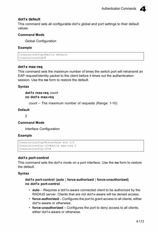
Authentication Commands 4
dot1x defaultThis command sets all configurable dot1x global and port settings to their default values.Command Mode
Global Configuration
Example
dot1x max-reqThis command sets the maximum number of times the switch port will retransmit an EAP request/identity packet to the client before it times out the authentication session. Use the no form to restore the default.
Syntax
dot1x max-req countno dot1x max-req
count – The maximum number of requests (Range: 1-10)
Default
2
Command Mode
Interface Configuration
Example
dot1x port-controlThis command sets the dot1x mode on a port interface. Use the no form to restore the default.
Syntax
dot1x port-control {auto | force-authorized | force-unauthorized}no dot1x port-control
• auto – Requires a dot1x-aware connected client to be authorized by the RADIUS server. Clients that are not dot1x-aware will be denied access.
• force-authorized – Configures the port to grant access to all clients, either dot1x-aware or otherwise.
• force-unauthorized – Configures the port to deny access to all clients, either dot1x-aware or otherwise.
Console(config)#dot1x defaultConsole(config)#
Console(config)#interface eth 1/2Console(config-if)#dot1x max-req 2Console(config-if)#
4-113
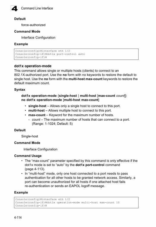
Command Line Interface4
Defaultforce-authorized
Command Mode
Interface Configuration
Example
dot1x operation-modeThis command allows single or multiple hosts (clients) to connect to an 802.1X-authorized port. Use the no form with no keywords to restore the default to single host. Use the no form with the multi-host max-count keywords to restore the default maximum count.
Syntax
dot1x operation-mode {single-host | multi-host [max-count count]}no dot1x operation-mode [multi-host max-count]
• single-host – Allows only a single host to connect to this port.• multi-host – Allows multiple host to connect to this port.• max-count – Keyword for the maximum number of hosts.
- count – The maximum number of hosts that can connect to a port. (Range: 1-1024; Default: 5)
Default
Single-host
Command Mode
Interface Configuration
Command Usage
• The “max-count” parameter specified by this command is only effective if the dot1x mode is set to “auto” by the dot1x port-control command (page 4-113).
• In “multi-host” mode, only one host connected to a port needs to pass authentication for all other hosts to be granted network access. Similarly, a port can become unauthorized for all hosts if one attached host fails re-authentication or sends an EAPOL logoff message.
Example
Console(config)#interface eth 1/2Console(config-if)#dot1x port-control autoConsole(config-if)#
Console(config)#interface eth 1/2Console(config-if)#dot1x operation-mode multi-host max-count 10 Console(config-if)#
4-114
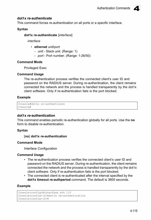
Authentication Commands 4
dot1x re-authenticateThis command forces re-authentication on all ports or a specific interface.Syntax
dot1x re-authenticate [interface]
interface
• ethernet unit/port- unit - Stack unit. (Range: 1) - port - Port number. (Range: 1-26/50)
Command Mode
Privileged Exec
Command Usage
The re-authentication process verifies the connected client’s user ID and password on the RADIUS server. During re-authentication, the client remains connected the network and the process is handled transparently by the dot1x client software. Only if re-authentication fails is the port blocked.
Example
dot1x re-authenticationThis command enables periodic re-authentication globally for all ports. Use the no form to disable re-authentication.
Syntax
[no] dot1x re-authentication
Command Mode
Interface Configuration
Command Usage
• The re-authentication process verifies the connected client’s user ID and password on the RADIUS server. During re-authentication, the client remains connected the network and the process is handled transparently by the dot1x client software. Only if re-authentication fails is the port blocked.
• The connected client is re-authenticated after the interval specified by the dot1x timeout re-authperiod command. The default is 3600 seconds.
Example
Console#dot1x re-authenticateConsole#
Console(config)#interface eth 1/2Console(config-if)#dot1x re-authenticationConsole(config-if)#
4-115
Command Line Interface4
Related Commandsdot1x timeout re-authperiod (4-116)
dot1x timeout quiet-periodThis command sets the time that a switch port waits after the Max Request Count has been exceeded before attempting to acquire a new client. Use the no form to reset the default.
Syntax
dot1x timeout quiet-period secondsno dot1x timeout quiet-period
seconds - The number of seconds. (Range: 1-65535)
Default
60 seconds
Command Mode
Interface Configuration
Example
dot1x timeout re-authperiodThis command sets the time period after which a connected client must be re-authenticated.
Syntax
dot1x timeout re-authperiod secondsno dot1x timeout re-authperiod
seconds - The number of seconds. (Range: 1-65535)
Default
3600 seconds
Command Mode
Interface Configuration
Example
Console(config)#interface eth 1/2Console(config-if)#dot1x timeout quiet-period 350Console(config-if)#
Console(config)#interface eth 1/2Console(config-if)#dot1x timeout re-authperiod 300Console(config-if)#
4-116
Authentication Commands 4
dot1x timeout tx-periodThis command sets the time that an interface on the switch waits during an authentication session before re-transmitting an EAP packet. Use the no form to reset to the default value.Syntax
dot1x timeout tx-period secondsno dot1x timeout tx-period
seconds - The number of seconds. (Range: 1-65535)
Default
30 seconds
Command Mode
Interface Configuration
Example
dot1x timeout supp-timeoutThis command sets the time that an interface on the switch waits for a response to an EAP request from a client before re-transmitting an EAP packet. Use the no form to reset to the default value.
Syntax
dot1x timeout supp-timeout secondsno dot1x timeout supp-timeout
seconds - The number of seconds. (Range: 1-65535)
Default
30 seconds
Command Mode
Interface Configuration
Command Usage
This command sets the timeout for EAP-request frames other than EAP-request/identity frames. If dot1x authentication is enabled on a port, the switch will initiate authentication when the port link state comes up. It will send an EAP-request/identity frame to the client to request its identity, followed by one or more requests for authentication information. It may also send other EAP-request frames to the client during an active connection as required for reauthentication.
Console(config)#interface eth 1/2Console(config-if)#dot1x timeout tx-period 300Console(config-if)#
4-117
Command Line Interface4
Exampleshow dot1xThis command shows general port authentication related settings on the switch or a specific interface.
Syntax
show dot1x [statistics] [interface interface]
• statistics - Displays dot1x status for each port.• interface
• ethernet unit/port- unit - Stack unit. (Range: 1) - port - Port number. (Range: 1-26/50)
Command Mode
Privileged Exec
Command Usage
This command displays the following information:
• Global 802.1X Parameters – Shows whether or not 802.1X port authentication is globally enabled on the switch.
• 802.1X Port Summary – Displays the port access control parameters for each interface, including the following items:- Status – Administrative state for port access control.- Operation Mode – Dot1x port control operation mode (page 4-114).- Mode – Dot1x port control mode (page 4-113).- Authorized – Authorization status (yes or n/a - not authorized).
• 802.1X Port Details – Displays the port access control parameters for each interface, including the following items:
- reauth-enabled – Periodic re-authentication (page 4-115).- reauth-period – Time after which a connected client must be
re-authenticated (page 4-116).- quiet-period – Time a port waits after Max Request Count is
exceeded before attempting to acquire a new client (page 4-116).
- tx-period – Time a port waits during authentication session before re-transmitting EAP packet (page 4-117).
- supplicant-timeout – Supplicant timeout.- server-timeout – Server timeout.- reauth-max – Maximum number of reauthentication attempts.
Console(config)#interface eth 1/2Console(config-if)#dot1x timeout supp-timeout 300Console(config-if)#
4-118
Authentication Commands 4
- max-req – Maximum number of times a port will retransmitan EAP request/identity packet to the client before it times out the authentication session (page 4-113).
- Status – Authorization status (authorized or not).- Operation Mode – Shows if single or multiple hosts (clients) can
connect to an 802.1X-authorized port.- Max Count – The maximum number of hosts allowed to
access this port (page 4-114).- Port-control – Shows the dot1x mode on a port as auto,
force-authorized, or force-unauthorized (page 4-113).
- Supplicant – MAC address of authorized client.- Current Identifier – The integer (0-255) used by the Authenticator to
identify the current authentication session.
• Authenticator State Machine - State – Current state (including initialize, disconnected,
connecting, authenticating, authenticated, aborting, held, force_authorized, force_unauthorized).
- Reauth Count – Number of times connecting state is re-entered.
• Backend State Machine - State – Current state (including request, response,
success, fail, timeout, idle, initialize).- Request Count – Number of EAP Request packets sent to the
Supplicant without receiving a response.- Identifier(Server) – Identifier carried in the most recent EAP Success,
Failure or Request packet received from the Authentication Server.
• Reauthentication State Machine - State – Current state (including initialize, reauthenticate).
4-119
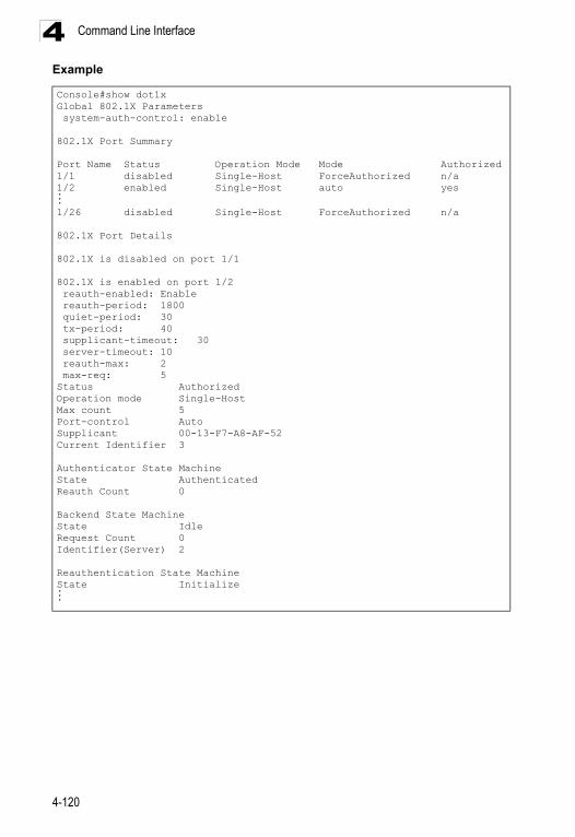
Command Line Interface4
ExampleConsole#show dot1xGlobal 802.1X Parameters system-auth-control: enable
802.1X Port Summary
Port Name Status Operation Mode Mode Authorized1/1 disabled Single-Host ForceAuthorized n/a1/2 enabled Single-Host auto yes...1/26 disabled Single-Host ForceAuthorized n/a
802.1X Port Details
802.1X is disabled on port 1/1
802.1X is enabled on port 1/2 reauth-enabled: Enable reauth-period: 1800 quiet-period: 30 tx-period: 40 supplicant-timeout: 30 server-timeout: 10 reauth-max: 2 max-req: 5Status AuthorizedOperation mode Single-HostMax count 5Port-control AutoSupplicant 00-13-F7-A8-AF-52Current Identifier 3
Authenticator State MachineState AuthenticatedReauth Count 0
Backend State MachineState IdleRequest Count 0Identifier(Server) 2
Reauthentication State MachineState Initialize...
4-120
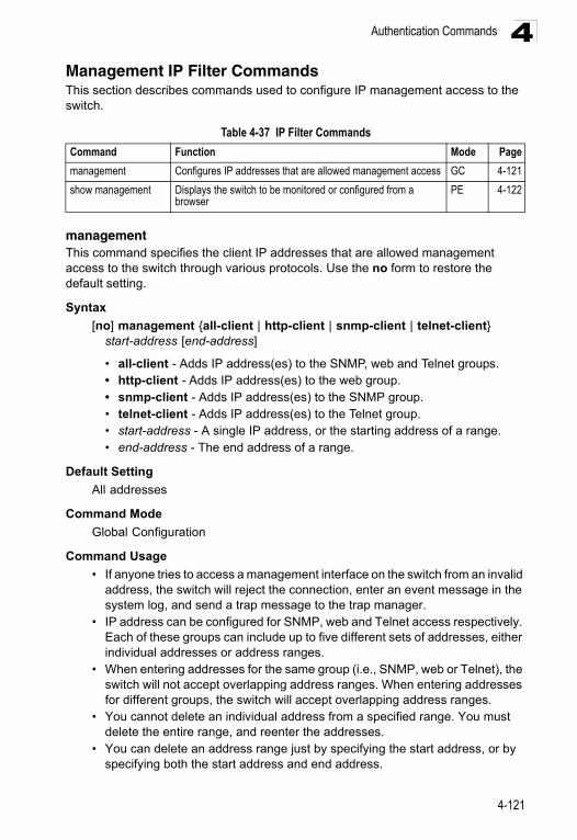
Authentication Commands 4
Management IP Filter CommandsThis section describes commands used to configure IP management access to the switch.managementThis command specifies the client IP addresses that are allowed management access to the switch through various protocols. Use the no form to restore the default setting.
Syntax
[no] management {all-client | http-client | snmp-client | telnet-client} start-address [end-address]
• all-client - Adds IP address(es) to the SNMP, web and Telnet groups.• http-client - Adds IP address(es) to the web group.• snmp-client - Adds IP address(es) to the SNMP group.• telnet-client - Adds IP address(es) to the Telnet group.• start-address - A single IP address, or the starting address of a range.• end-address - The end address of a range.
Default Setting
All addresses
Command Mode
Global Configuration
Command Usage
• If anyone tries to access a management interface on the switch from an invalid address, the switch will reject the connection, enter an event message in the system log, and send a trap message to the trap manager.
• IP address can be configured for SNMP, web and Telnet access respectively. Each of these groups can include up to five different sets of addresses, either individual addresses or address ranges.
• When entering addresses for the same group (i.e., SNMP, web or Telnet), the switch will not accept overlapping address ranges. When entering addresses for different groups, the switch will accept overlapping address ranges.
• You cannot delete an individual address from a specified range. You must delete the entire range, and reenter the addresses.
• You can delete an address range just by specifying the start address, or by specifying both the start address and end address.
Table 4-37 IP Filter Commands
Command Function Mode Page
management Configures IP addresses that are allowed management access GC 4-121
show management Displays the switch to be monitored or configured from a browser
PE 4-122
4-121
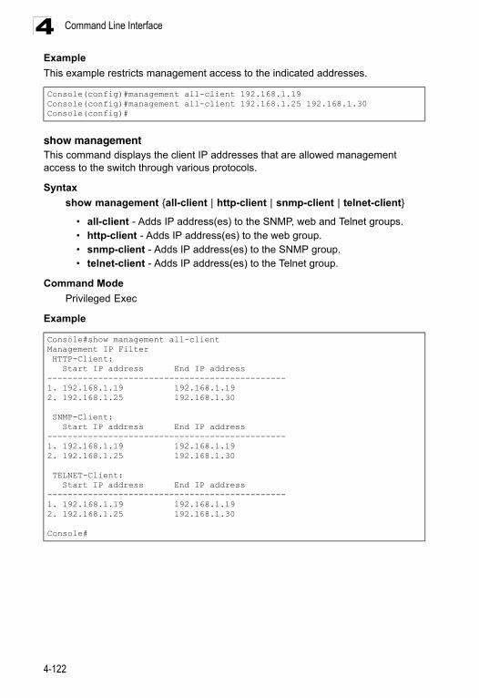
Command Line Interface4
ExampleThis example restricts management access to the indicated addresses.
show managementThis command displays the client IP addresses that are allowed management access to the switch through various protocols.
Syntax
show management {all-client | http-client | snmp-client | telnet-client}
• all-client - Adds IP address(es) to the SNMP, web and Telnet groups.• http-client - Adds IP address(es) to the web group.• snmp-client - Adds IP address(es) to the SNMP group.• telnet-client - Adds IP address(es) to the Telnet group.
Command Mode
Privileged Exec
Example
Console(config)#management all-client 192.168.1.19Console(config)#management all-client 192.168.1.25 192.168.1.30Console(config)#
Console#show management all-clientManagement IP Filter HTTP-Client: Start IP address End IP address-----------------------------------------------1. 192.168.1.19 192.168.1.192. 192.168.1.25 192.168.1.30
SNMP-Client: Start IP address End IP address-----------------------------------------------1. 192.168.1.19 192.168.1.192. 192.168.1.25 192.168.1.30
TELNET-Client: Start IP address End IP address-----------------------------------------------1. 192.168.1.19 192.168.1.192. 192.168.1.25 192.168.1.30
Console#
4-122
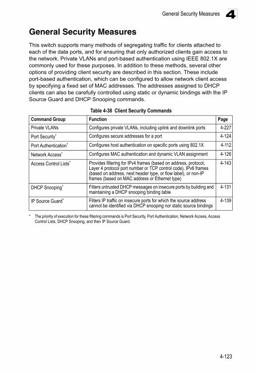
General Security Measures 4
General Security MeasuresThis switch supports many methods of segregating traffic for clients attached to each of the data ports, and for ensuring that only authorized clients gain access to the network. Private VLANs and port-based authentication using IEEE 802.1X are commonly used for these purposes. In addition to these methods, several other options of providing client security are described in this section. These include port-based authentication, which can be configured to allow network client access by specifying a fixed set of MAC addresses. The addresses assigned to DHCP clients can also be carefully controlled using static or dynamic bindings with the IP Source Guard and DHCP Snooping commands.Table 4-38 Client Security Commands
Command Group Function Page
Private VLANs Configures private VLANs, including uplink and downlink ports 4-227
Port Security*
* The priority of execution for these filtering commands is Port Security, Port Authentication, Network Access, Access Control Lists, DHCP Snooping, and then IP Source Guard.
Configures secure addresses for a port 4-124
Port Authentication* Configures host authentication on specific ports using 802.1X 4-112
Network Access* Configures MAC authentication and dynamic VLAN assignment 4-126
Access Control Lists* Provides filtering for IPv4 frames (based on address, protocol, Layer 4 protocol port number or TCP control code), IPv6 frames (based on address, next header type, or flow label), or non-IP frames (based on MAC address or Ethernet type)
4-143
DHCP Snooping* Filters untrusted DHCP messages on insecure ports by building and maintaining a DHCP snooping binding table
4-131
IP Source Guard* Filters IP traffic on insecure ports for which the source address cannot be identified via DHCP snooping nor static source bindings
4-139
4-123
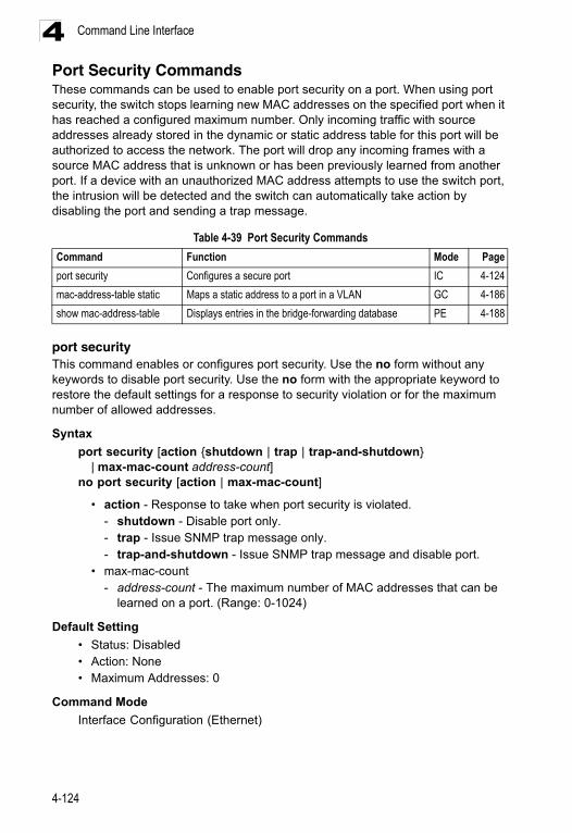
Command Line Interface4
Port Security CommandsThese commands can be used to enable port security on a port. When using port security, the switch stops learning new MAC addresses on the specified port when it has reached a configured maximum number. Only incoming traffic with source addresses already stored in the dynamic or static address table for this port will be authorized to access the network. The port will drop any incoming frames with a source MAC address that is unknown or has been previously learned from another port. If a device with an unauthorized MAC address attempts to use the switch port, the intrusion will be detected and the switch can automatically take action by disabling the port and sending a trap message.port securityThis command enables or configures port security. Use the no form without any keywords to disable port security. Use the no form with the appropriate keyword to restore the default settings for a response to security violation or for the maximum number of allowed addresses.
Syntax
port security [action {shutdown | trap | trap-and-shutdown} | max-mac-count address-count]
no port security [action | max-mac-count]
• action - Response to take when port security is violated. - shutdown - Disable port only.- trap - Issue SNMP trap message only.- trap-and-shutdown - Issue SNMP trap message and disable port.
• max-mac-count- address-count - The maximum number of MAC addresses that can be
learned on a port. (Range: 0-1024)
Default Setting
• Status: Disabled• Action: None• Maximum Addresses: 0
Command Mode
Interface Configuration (Ethernet)
Table 4-39 Port Security Commands
Command Function Mode Page
port security Configures a secure port IC 4-124
mac-address-table static Maps a static address to a port in a VLAN GC 4-186
show mac-address-table Displays entries in the bridge-forwarding database PE 4-188
4-124
General Security Measures 4
Command Usage• If you enable port security, the switch stops learning new MAC addresses on the specified port when it has reached a configured maximum number. Only incoming traffic with source addresses already stored in the dynamic or static address table will be accepted.
• Use the port security command to enable security on a port. Then use the port security action command to set the response to a port security violation, and the port security max-mac-count command to set the maximum number of addresses allowed on a port.
• You can also manually add secure addresses with the mac-address-table static command.
• A secure port has the following restrictions: - Cannot be connected to a network interconnection device. - Cannot be a trunk port.
• If a port is disabled due to a security violation, it must be manually re-enabled using the no shutdown command.
Example
The following example enables port security for port 5, and sets the response to a security violation to issue a trap message:
Related Commands
shutdown (4-160)mac-address-table static (4-186)show mac-address-table (4-188)
Console(config)#interface ethernet 1/5Console(config-if)#port security action trap
4-125
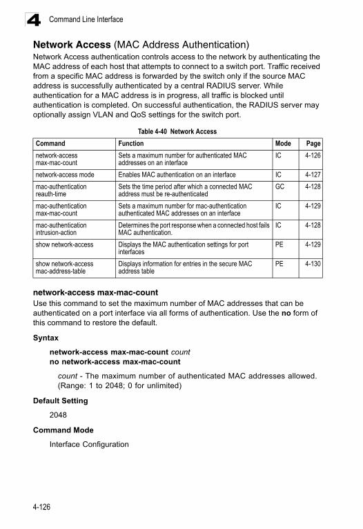
Command Line Interface4
Network Access (MAC Address Authentication)Network Access authentication controls access to the network by authenticating the MAC address of each host that attempts to connect to a switch port. Traffic received from a specific MAC address is forwarded by the switch only if the source MAC address is successfully authenticated by a central RADIUS server. While authentication for a MAC address is in progress, all traffic is blocked until authentication is completed. On successful authentication, the RADIUS server may optionally assign VLAN and QoS settings for the switch port.network-access max-mac-countUse this command to set the maximum number of MAC addresses that can be authenticated on a port interface via all forms of authentication. Use the no form of this command to restore the default.
Syntax
network-access max-mac-count countno network-access max-mac-count
count - The maximum number of authenticated MAC addresses allowed. (Range: 1 to 2048; 0 for unlimited)
Default Setting
2048
Command Mode
Interface Configuration
Table 4-40 Network Access
Command Function Mode Page
network-access max-mac-count
Sets a maximum number for authenticated MAC addresses on an interface
IC 4-126
network-access mode Enables MAC authentication on an interface IC 4-127
mac-authentication reauth-time
Sets the time period after which a connected MAC address must be re-authenticated
GC 4-128
mac-authentication max-mac-count
Sets a maximum number for mac-authentication authenticated MAC addresses on an interface
IC 4-129
mac-authentication intrusion-action
Determines the port response when a connected host fails MAC authentication.
IC 4-128
show network-access Displays the MAC authentication settings for port interfaces
PE 4-129
show network-access mac-address-table
Displays information for entries in the secure MAC address table
PE 4-130
4-126
General Security Measures 4
Command UsageThe maximum number of MAC addresses per port is 2048, and the maximum number of secure MAC addresses supported for the switch system is 1024. When the limit is reached, all new MAC addresses are treated as authentication failures.
Example
network-access modeUse this command to enable network access authentication on a port. Use the no form of this command to disable network access authentication.
Syntax
[no] network-access mode mac-authentication
Default Setting
Disabled
Command Mode
Interface Configuration
Command Usage
• When enabled on a port, the authentication process sends a Password Authentication Protocol (PAP) request to a configured RADIUS server. The username and password are both equal to the MAC address being authenticated.
• On the RADIUS server, PAP username and passwords must be configured in the MAC address format XX-XX-XX-XX-XX-XX (all in upper case).
• Authenticated MAC addresses are stored as dynamic entries in the switch’s secure MAC address table and are removed when the aging time expires. The maximum number of secure MAC addresses supported for the switch system is 1024.
• Configured static MAC addresses are added to the secure address table when seen on a switch port. Static addresses are treated as authenticated without sending a request to a RADIUS server.
• MAC authentication, 802.1X, and port security cannot be configured together on the same port. Only one security mechanism can be applied.
• MAC authentication cannot be configured on trunk ports.• When port status changes to down, all MAC addresses are cleared from the
secure MAC address table. Static VLAN assignments are not restored.• The RADIUS server may optionally return a VLAN identifier list. VLAN
identifier list is carried in the “Tunnel-Private-Group-ID” attribute. The VLAN list can contain multiple VLAN identifiers in the format “1u,2t,” where “u”
Console(config-if)#network-access max-mac-count 5Console(config-if)#
4-127
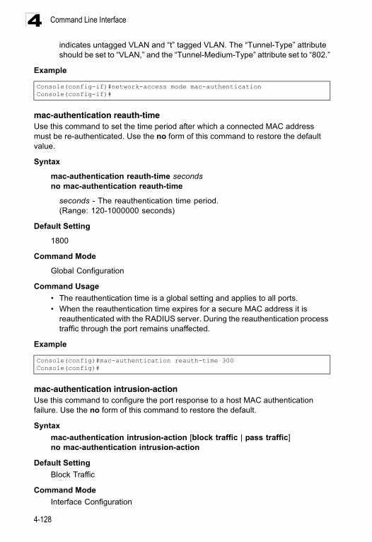
Command Line Interface4
indicates untagged VLAN and “t” tagged VLAN. The “Tunnel-Type” attribute should be set to “VLAN,” and the “Tunnel-Medium-Type” attribute set to “802.”Example
mac-authentication reauth-timeUse this command to set the time period after which a connected MAC address must be re-authenticated. Use the no form of this command to restore the default value.
Syntax
mac-authentication reauth-time secondsno mac-authentication reauth-time
seconds - The reauthentication time period. (Range: 120-1000000 seconds)
Default Setting
1800
Command Mode
Global Configuration
Command Usage
• The reauthentication time is a global setting and applies to all ports.• When the reauthentication time expires for a secure MAC address it is
reauthenticated with the RADIUS server. During the reauthentication process traffic through the port remains unaffected.
Example
mac-authentication intrusion-actionUse this command to configure the port response to a host MAC authentication failure. Use the no form of this command to restore the default.
Syntax
mac-authentication intrusion-action [block traffic | pass traffic]no mac-authentication intrusion-action
Default Setting
Block Traffic
Command Mode
Interface Configuration
Console(config-if)#network-access mode mac-authenticationConsole(config-if)#
Console(config)#mac-authentication reauth-time 300Console(config)#
4-128
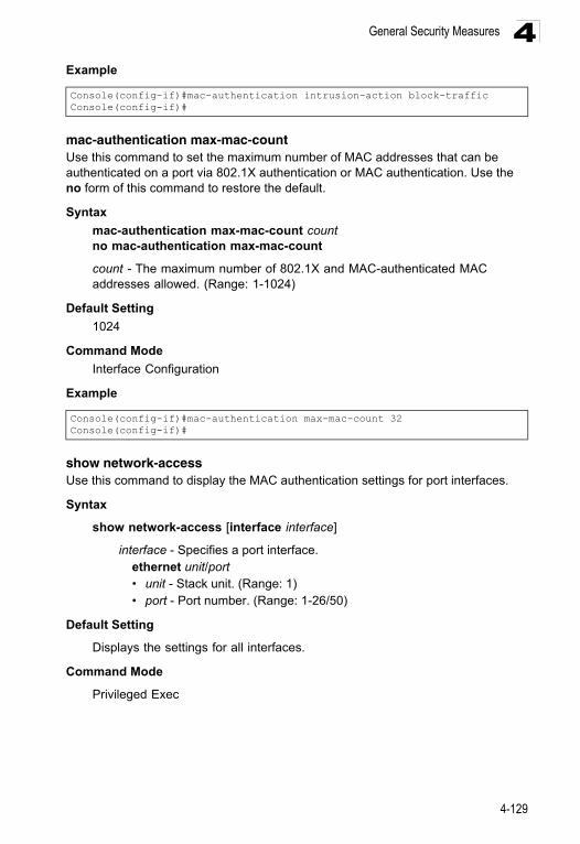
General Security Measures 4
Examplemac-authentication max-mac-countUse this command to set the maximum number of MAC addresses that can be authenticated on a port via 802.1X authentication or MAC authentication. Use the no form of this command to restore the default.
Syntax
mac-authentication max-mac-count countno mac-authentication max-mac-count
count - The maximum number of 802.1X and MAC-authenticated MAC addresses allowed. (Range: 1-1024)
Default Setting
1024
Command Mode
Interface Configuration
Example
show network-accessUse this command to display the MAC authentication settings for port interfaces.
Syntax
show network-access [interface interface]
interface - Specifies a port interface.ethernet unit/port• unit - Stack unit. (Range: 1) • port - Port number. (Range: 1-26/50)
Default Setting
Displays the settings for all interfaces.
Command Mode
Privileged Exec
Console(config-if)#mac-authentication intrusion-action block-trafficConsole(config-if)#
Console(config-if)#mac-authentication max-mac-count 32Console(config-if)#
4-129
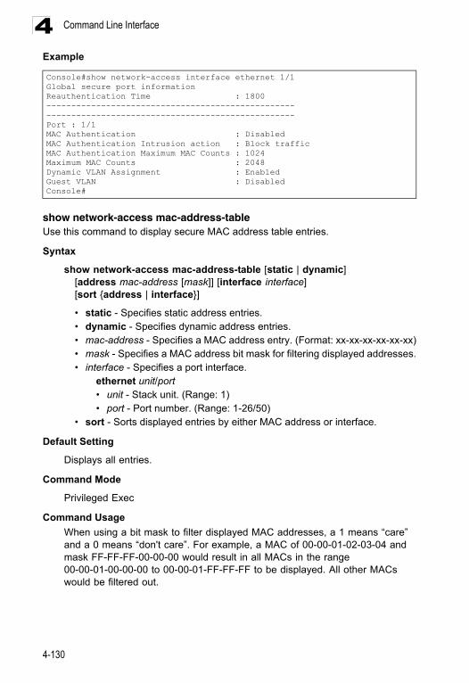
Command Line Interface4
Exampleshow network-access mac-address-tableUse this command to display secure MAC address table entries.
Syntax
show network-access mac-address-table [static | dynamic] [address mac-address [mask]] [interface interface] [sort {address | interface}]
• static - Specifies static address entries.• dynamic - Specifies dynamic address entries.• mac-address - Specifies a MAC address entry. (Format: xx-xx-xx-xx-xx-xx)• mask - Specifies a MAC address bit mask for filtering displayed addresses.• interface - Specifies a port interface.
ethernet unit/port• unit - Stack unit. (Range: 1) • port - Port number. (Range: 1-26/50)
• sort - Sorts displayed entries by either MAC address or interface.
Default Setting
Displays all entries.
Command Mode
Privileged Exec
Command Usage
When using a bit mask to filter displayed MAC addresses, a 1 means “care” and a 0 means “don't care”. For example, a MAC of 00-00-01-02-03-04 and mask FF-FF-FF-00-00-00 would result in all MACs in the range 00-00-01-00-00-00 to 00-00-01-FF-FF-FF to be displayed. All other MACs would be filtered out.
Console#show network-access interface ethernet 1/1Global secure port informationReauthentication Time : 1800----------------------------------------------------------------------------------------------------Port : 1/1MAC Authentication : DisabledMAC Authentication Intrusion action : Block trafficMAC Authentication Maximum MAC Counts : 1024Maximum MAC Counts : 2048Dynamic VLAN Assignment : EnabledGuest VLAN : DisabledConsole#
4-130
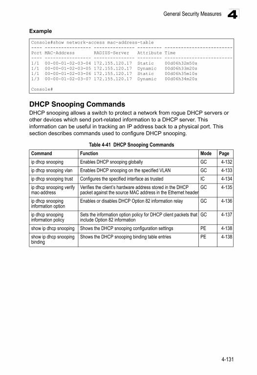
General Security Measures 4
ExampleDHCP Snooping CommandsDHCP snooping allows a switch to protect a network from rogue DHCP servers or other devices which send port-related information to a DHCP server. This information can be useful in tracking an IP address back to a physical port. This section describes commands used to configure DHCP snooping.
Console#show network-access mac-address-table---- ----------------- --------------- --------- -------------------------Port MAC-Address RADIUS-Server Attribute Time---- ----------------- --------------- --------- -------------------------1/1 00-00-01-02-03-04 172.155.120.17 Static 00d06h32m50s1/1 00-00-01-02-03-05 172.155.120.17 Dynamic 00d06h33m20s1/1 00-00-01-02-03-06 172.155.120.17 Static 00d06h35m10s1/3 00-00-01-02-03-07 172.155.120.17 Dynamic 00d06h34m20s
Console#
Table 4-41 DHCP Snooping Commands
Command Function Mode Page
ip dhcp snooping Enables DHCP snooping globally GC 4-132
ip dhcp snooping vlan Enables DHCP snooping on the specified VLAN GC 4-133
ip dhcp snooping trust Configures the specified interface as trusted IC 4-134
ip dhcp snooping verify mac-address
Verifies the client’s hardware address stored in the DHCP packet against the source MAC address in the Ethernet header
GC 4-135
ip dhcp snooping information option
Enables or disables DHCP Option 82 information relay GC 4-136
ip dhcp snooping information policy
Sets the information option policy for DHCP client packets that include Option 82 information
GC 4-137
show ip dhcp snooping Shows the DHCP snooping configuration settings PE 4-138
show ip dhcp snooping binding
Shows the DHCP snooping binding table entries PE 4-138
4-131
Command Line Interface4
ip dhcp snoopingThis command enables DHCP snooping globally. Use the no form to restore the default setting.Syntax
[no] ip dhcp snooping
Default Setting
Disabled
Command Mode
Global Configuration
Command Usage
• Network traffic may be disrupted when malicious DHCP messages are received from an outside source. DHCP snooping is used to filter DHCP messages received on an insecure interface from outside the network or fire wall. When DHCP snooping is enabled globally by this command, and enabled on a VLAN interface by the ip dhcp snooping vlan command (page 4-133), DHCP messages received on an untrusted interface (as specified by the no ip dhcp snooping trust command, page 4-134) from a device not listed in the DHCP snooping table will be dropped.
• When enabled, DHCP messages entering an untrusted interface are filtered based upon dynamic entries learned via DHCP snooping.
• Table entries are only learned for untrusted interfaces. Each entry includes a MAC address, IP address, lease time, VLAN identifier, and port identifier.
• When DHCP snooping is enabled, the rate limit for the number of DHCP messages that can be processed by the switch is 100 packets per second. Any DHCP packets in excess of this limit are dropped.
• Filtering rules are implemented as follows:- If the global DHCP snooping is disabled, all DHCP packets are forwarded.- If DHCP snooping is enabled globally, and also enabled on the VLAN where
the DHCP packet is received, all DHCP packets are forwarded for a trusted port. If the received packet is a DHCP ACK message, a dynamic DHCP snooping entry is also added to the binding table.
- If DHCP snooping is enabled globally, and also enabled on the VLAN where the DHCP packet is received, but the port is not trusted, it is processed as follows:* If the DHCP packet is a reply packet from a DHCP server (including
OFFER, ACK or NAK messages), the packet is dropped.* If the DHCP packet is from a client, such as a DECLINE or RELEASE
message, the switch forwards the packet only if the corresponding entry is found in the binding table.
* If the DHCP packet is from client, such as a DISCOVER, REQUEST, INFORM, DECLINE or RELEASE message, the packet is forwarded if MAC address verification is disabled (as specified by the ip dhcp snooping verify mac-address command, page 4-135). However, if
4-132
General Security Measures 4
MAC address verification is enabled, then the packet will only be forwarded if the client’s hardware address stored in the DHCP packet is the same as the source MAC address in the Ethernet header.* If the DHCP packet is not a recognizable type, it is dropped.- If a DHCP packet from a client passes the filtering criteria above, it will only
be forwarded to trusted ports in the same VLAN.- If a DHCP packet is from server is received on a trusted port, it will be
forwarded to both trusted and untrusted ports in the same VLAN.• If the DHCP snooping is globally disabled, all dynamic bindings are removed
from the binding table.• Additional considerations when the switch itself is a DHCP client – The port(s)
through which the switch submits a client request to the DHCP server must be configured as trusted (ip dhcp snooping trust, page 4-134). Note that the switch will not add a dynamic entry for itself to the binding table when it receives an ACK message from a DHCP server. Also, when the switch sends out DHCP client packets for itself, no filtering takes place. However, when the switch receives any messages from a DHCP server, any packets received from untrusted ports are dropped.
Example
This example enables DHCP snooping globally for the switch.
Related Commands
ip dhcp snooping vlan (4-133)ip dhcp snooping trust (4-134)
ip dhcp snooping vlanThis command enables DHCP snooping on the specified VLAN. Use the no form to restore the default setting.
Syntax
[no] ip dhcp snooping vlan vlan-id
vlan-id - ID of a configured VLAN (Range: 1-4094)
Default Setting
Disabled
Command Mode
Global Configuration
Command Usage
• When DHCP snooping enabled globally using the ip dhcp snooping command (page 4-132), and enabled on a VLAN with this command, DHCP
Console(config)#ip dhcp snoopingConsole(config)#
4-133
Command Line Interface4
packet filtering will be performed on any untrusted ports within the VLAN as specified by the ip dhcp snooping trust command (page 4-134).• When the DHCP snooping is globally disabled, DHCP snooping can still be configured for specific VLANs, but the changes will not take effect until DHCP snooping is globally re-enabled.
• When DHCP snooping is globally enabled, configuration changes for specific VLANs have the following effects:- If DHCP snooping is disabled on a VLAN, all dynamic bindings learned for
this VLAN are removed from the binding table.
Example
This example enables DHCP snooping for VLAN 1.
Related Commands
ip dhcp snooping (4-132)ip dhcp snooping trust (4-134)
ip dhcp snooping trustThis command configures the specified interface as trusted. Use the no form to restore the default setting.
Syntax
[no] ip dhcp snooping trust
Default Setting
All interfaces are untrusted
Command Mode
Interface Configuration (Ethernet, Port Channel)
Command Usage
• A trusted interface is an interface that is configured to receive only messages from within the network. An untrusted interface is an interface that is configured to receive messages from outside the network or fire wall.
• Set all ports connected to DHCP servers within the local network or fire wall to trusted, and all other ports outside the local network or fire wall to untrusted.
• When DHCP snooping ia enabled globally using the ip dhcp snooping command (page 4-132), and enabled on a VLAN with ip dhcp snooping vlan command (page 4-133), DHCP packet filtering will be performed on any untrusted ports within the VLAN according to the default status, or as specifically configured for an interface with the no ip dhcp snooping trust command.
• When an untrusted port is changed to a trusted port, all the dynamic DHCP snooping bindings associated with this port are removed.
Console(config)#ip dhcp snooping vlan 1Console(config)#
4-134
General Security Measures 4
• Additional considerations when the switch itself is a DHCP client – The port(s)through which it submits a client request to the DHCP server must be configured as trusted.
Example
This example sets port 5 to untrusted.
Related Commands
ip dhcp snooping (4-132)ip dhcp snooping vlan (4-133)
ip dhcp snooping verify mac-addressThis command verifies the client’s hardware address stored in the DHCP packet against the source MAC address in the Ethernet header. Use the no form to disable this function.
Syntax
[no] ip dhcp snooping verify mac-address
Default Setting
Enabled
Command Mode
Global Configuration
Command Usage
If MAC address verification is enabled, and the source MAC address in the Ethernet header of the packet is not same as the client’s hardware address in the DHCP packet, the packet is dropped.
Example
This example enables MAC address verification.
Related Commands
ip dhcp snooping (4-132)ip dhcp snooping vlan (4-133)ip dhcp snooping trust (4-134)
Console(config)#interface ethernet 1/5Console(config-if)#no ip dhcp snooping trustConsole(config-if)#
Console(config)#ip dhcp snooping verify mac-addressConsole(config)#
4-135
Command Line Interface4
ip dhcp snooping information optionThis command enables the DHCP Option 82 information relay for the switch. Use the no form to disable this function.Syntax
[no] ip dhcp snooping information option
Default Setting
Disabled
Command Mode
Global Configuration
Command Usage
• DHCP provides a relay mechanism for sending information about the switch and its DHCP clients to the DHCP server. Known as DHCP Option 82, it allows compatible DHCP servers to use the information when assigning IP addresses, or to set other services or policies for clients.
• When the DHCP Snooping Information Option is enabled, the requesting client (or an intermediate relay agent that has used the information fields to describe itself) can be identified in the DHCP request packets forwarded by the switch and in reply packets sent back from the DHCP server, by the switch port to which they are connected rather than just their MAC address. DHCP client-server exchange messages are then forwarded directly between the server and client without having to flood them to the entire VLAN.
• DHCP snooping must be enabled on the switch for the DHCP Option 82 information to be inserted into packets.
• Use the ip dhcp snooping information option command (page 4-136) to specify how to handle DHCP client request packets which already contain Option 82 information.
Example
This example enables the DHCP Snooping Information Option.
Console(config)#ip dhcp snooping information optionConsole(config)#
4-136
General Security Measures 4
ip dhcp snooping information policyThis command sets the DHCP snooping information option policy for DHCP client packets that include Option 82 information.Syntax
ip dhcp snooping information policy {drop | keep | replace}• drop - Drops the client’s request packet instead of relaying it.• keep - Retains the Option 82 information in the client request, and forwards
the packets to trusted ports.• replace - Replaces the Option 82 information in the client’s request with
information about the relay agent itself, inserts the relay agent’s address (when DHCP snooping is enabled), and forwards the packets to trusted ports.
Default Setting
replace
Command Mode
Global Configuration
Command Usage
When the switch receives DHCP packets from clients that already include DHCP Option 82 information, the switch can be configured to set the action policy for these packets. The switch can drop the DHCP packets, keep the existing information, or replace it with the switch’s relay information.
Example
Console(config)#ip dhcp snooping information policy dropConsole(config)#
4-137
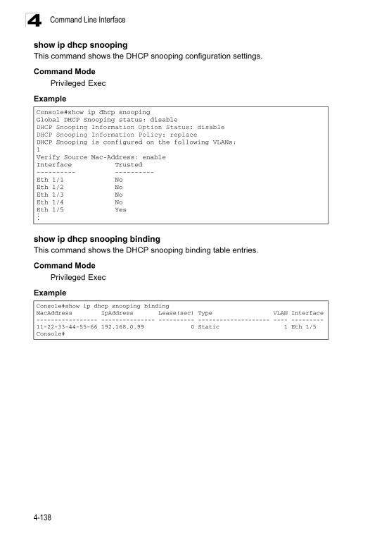
Command Line Interface4
show ip dhcp snoopingThis command shows the DHCP snooping configuration settings.Command Mode
Privileged Exec
Example
show ip dhcp snooping bindingThis command shows the DHCP snooping binding table entries.
Command Mode
Privileged Exec
Example
Console#show ip dhcp snoopingGlobal DHCP Snooping status: disable DHCP Snooping Information Option Status: disableDHCP Snooping Information Policy: replaceDHCP Snooping is configured on the following VLANs:1Verify Source Mac-Address: enableInterface Trusted---------- ----------Eth 1/1 NoEth 1/2 NoEth 1/3 NoEth 1/4 NoEth 1/5 Yes...
Console#show ip dhcp snooping bindingMacAddress IpAddress Lease(sec) Type VLAN Interface----------------- --------------- ---------- -------------------- ---- ---------11-22-33-44-55-66 192.168.0.99 0 Static 1 Eth 1/5Console#
4-138
General Security Measures 4
IP Source Guard CommandsIP Source Guard is a security feature that filters IP traffic on network interfaces based on manually configured entries in the IP Source Guard table, or dynamic entries in the DHCP Snooping table when enabled (see "DHCP Snooping Commands" on page 4-131). IP source guard can be used to prevent traffic attacks caused when a host tries to use the IP address of a neighbor to access the network. This section describes commands used to configure IP Source Guard.ip source-guardThis command configures the switch to filter inbound traffic based source IP address, or source IP address and corresponding MAC address. Use the no form to disable this function.
Syntax
ip source-guard {sip | sip-mac}no ip source-guard
• sip - Filters traffic based on IP addresses stored in the binding table.• sip-mac - Filters traffic based on IP addresses and corresponding MAC
addresses stored in the binding table.
Default Setting
Disabled
Command Mode
Interface Configuration (Ethernet)
Command Usage
• Source guard is used to filter traffic on an insecure port which receives messages from outside the network or fire wall, and therefore may be subject to traffic attacks caused by a host trying to use the IP address of a neighbor.
• Setting source guard mode to “sip” or “sip-mac” enables this function on the selected port. Use the “sip” option to check the VLAN ID, source IP address, and port number against all entries in the binding table. Use the “sip-mac” option to check these same parameters, plus the source MAC address. Use the no source guard command to disable this function on the selected port.
Table 4-42 IP Source Guard Commands
Command Function Mode Page
ip source-guard Configures the switch to filter inbound traffic based on source IP address, or source IP address and corresponding MAC address
IC 4-139
ip source-guard binding
Adds a static address to the source-guard binding table GC 4-141
show ip source-guard
Shows whether source guard is enabled or disabled on each interface
PE 4-142
show ip source-guard binding
Shows the source guard binding table PE 4-142
4-139
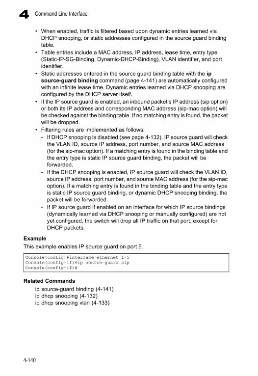
Command Line Interface4
• When enabled, traffic is filtered based upon dynamic entries learned viaDHCP snooping, or static addresses configured in the source guard binding table.
• Table entries include a MAC address, IP address, lease time, entry type (Static-IP-SG-Binding, Dynamic-DHCP-Binding), VLAN identifier, and port identifier.
• Static addresses entered in the source guard binding table with the ip source-guard binding command (page 4-141) are automatically configured with an infinite lease time. Dynamic entries learned via DHCP snooping are configured by the DHCP server itself.
• If the IP source guard is enabled, an inbound packet’s IP address (sip option) or both its IP address and corresponding MAC address (sip-mac option) will be checked against the binding table. If no matching entry is found, the packet will be dropped.
• Filtering rules are implemented as follows:- If DHCP snooping is disabled (see page 4-132), IP source guard will check
the VLAN ID, source IP address, port number, and source MAC address (for the sip-mac option). If a matching entry is found in the binding table and the entry type is static IP source guard binding, the packet will be forwarded.
- If the DHCP snooping is enabled, IP source guard will check the VLAN ID, source IP address, port number, and source MAC address (for the sip-mac option). If a matching entry is found in the binding table and the entry type is static IP source guard binding, or dynamic DHCP snooping binding, the packet will be forwarded.
- If IP source guard if enabled on an interface for which IP source bindings (dynamically learned via DHCP snooping or manually configured) are not yet configured, the switch will drop all IP traffic on that port, except for DHCP packets.
Example
This example enables IP source guard on port 5.
Related Commands
ip source-guard binding (4-141)ip dhcp snooping (4-132)ip dhcp snooping vlan (4-133)
Console(config)#interface ethernet 1/5Console(config-if)#ip source-guard sipConsole(config-if)#
4-140
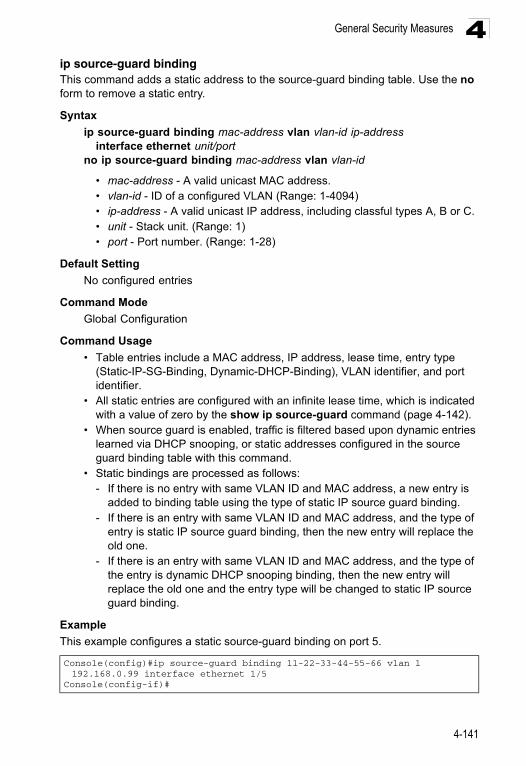
General Security Measures 4
ip source-guard bindingThis command adds a static address to the source-guard binding table. Use the no form to remove a static entry.Syntax
ip source-guard binding mac-address vlan vlan-id ip-address interface ethernet unit/port
no ip source-guard binding mac-address vlan vlan-id
• mac-address - A valid unicast MAC address. • vlan-id - ID of a configured VLAN (Range: 1-4094) • ip-address - A valid unicast IP address, including classful types A, B or C. • unit - Stack unit. (Range: 1) • port - Port number. (Range: 1-28)
Default Setting
No configured entries
Command Mode
Global Configuration
Command Usage
• Table entries include a MAC address, IP address, lease time, entry type (Static-IP-SG-Binding, Dynamic-DHCP-Binding), VLAN identifier, and port identifier.
• All static entries are configured with an infinite lease time, which is indicated with a value of zero by the show ip source-guard command (page 4-142).
• When source guard is enabled, traffic is filtered based upon dynamic entries learned via DHCP snooping, or static addresses configured in the source guard binding table with this command.
• Static bindings are processed as follows:- If there is no entry with same VLAN ID and MAC address, a new entry is
added to binding table using the type of static IP source guard binding.- If there is an entry with same VLAN ID and MAC address, and the type of
entry is static IP source guard binding, then the new entry will replace the old one.
- If there is an entry with same VLAN ID and MAC address, and the type of the entry is dynamic DHCP snooping binding, then the new entry will replace the old one and the entry type will be changed to static IP source guard binding.
Example
This example configures a static source-guard binding on port 5.
Console(config)#ip source-guard binding 11-22-33-44-55-66 vlan 1 192.168.0.99 interface ethernet 1/5
Console(config-if)#
4-141
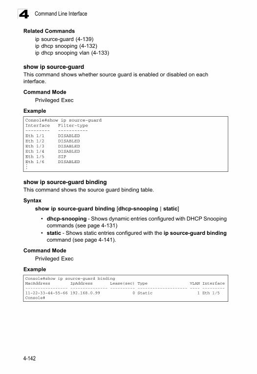
Command Line Interface4
Related Commandsip source-guard (4-139)ip dhcp snooping (4-132)ip dhcp snooping vlan (4-133)
show ip source-guardThis command shows whether source guard is enabled or disabled on each interface.
Command Mode
Privileged Exec
Example
show ip source-guard bindingThis command shows the source guard binding table.
Syntax
show ip source-guard binding [dhcp-snooping | static]
• dhcp-snooping - Shows dynamic entries configured with DHCP Snooping commands (see page 4-131)
• static - Shows static entries configured with the ip source-guard binding command (see page 4-141).
Command Mode
Privileged Exec
Example
Console#show ip source-guardInterface Filter-type--------- -----------Eth 1/1 DISABLEDEth 1/2 DISABLEDEth 1/3 DISABLEDEth 1/4 DISABLEDEth 1/5 SIPEth 1/6 DISABLED...
Console#show ip source-guard bindingMacAddress IpAddress Lease(sec) Type VLAN Interface----------------- --------------- ---------- -------------------- ---- ---------11-22-33-44-55-66 192.168.0.99 0 Static 1 Eth 1/5Console#
4-142
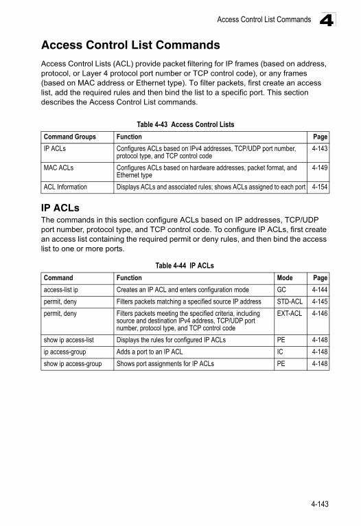
Access Control List Commands 4
Access Control List CommandsAccess Control Lists (ACL) provide packet filtering for IP frames (based on address, protocol, or Layer 4 protocol port number or TCP control code), or any frames (based on MAC address or Ethernet type). To filter packets, first create an access list, add the required rules and then bind the list to a specific port. This section describes the Access Control List commands.IP ACLsThe commands in this section configure ACLs based on IP addresses, TCP/UDP port number, protocol type, and TCP control code. To configure IP ACLs, first create an access list containing the required permit or deny rules, and then bind the access list to one or more ports.
Table 4-43 Access Control Lists
Command Groups Function Page
IP ACLs Configures ACLs based on IPv4 addresses, TCP/UDP port number, protocol type, and TCP control code
4-143
MAC ACLs Configures ACLs based on hardware addresses, packet format, and Ethernet type
4-149
ACL Information Displays ACLs and associated rules; shows ACLs assigned to each port 4-154
Table 4-44 IP ACLs
Command Function Mode Page
access-list ip Creates an IP ACL and enters configuration mode GC 4-144
permit, deny Filters packets matching a specified source IP address STD-ACL 4-145
permit, deny Filters packets meeting the specified criteria, including source and destination IPv4 address, TCP/UDP port number, protocol type, and TCP control code
EXT-ACL 4-146
show ip access-list Displays the rules for configured IP ACLs PE 4-148
ip access-group Adds a port to an IP ACL IC 4-148
show ip access-group Shows port assignments for IP ACLs PE 4-148
4-143
Command Line Interface4
access-list ip This command adds an IP access list and enters configuration mode for standard or extended IP ACLs. Use the no form to remove the specified ACL.Syntax
[no] access-list ip {standard | extended} acl-name
• standard – Specifies an ACL that filters packets based on the source IP address.
• extended – Specifies an ACL that filters packets based on the source or destination IP address, and other more specific criteria.
• acl-name – Name of the ACL. (Maximum length: 16 characters, no spaces)
Default Setting
None
Command Mode
Global Configuration
Command Usage
• When you create a new ACL or enter configuration mode for an existing ACL, use the permit or deny command to add new rules to the bottom of the list. To create an ACL, you must add at least one rule to the list.
• To remove a rule, use the no permit or no deny command followed by the exact text of a previously configured rule.
• An ACL can contain up to 96 rules.
Example
Related Commands
permit, deny 4-145ip access-group (4-148)show ip access-list (4-148)
Console(config)#access-list ip standard davidConsole(config-std-acl)#
4-144
Access Control List Commands 4
permit, deny (Standard ACL) This command adds a rule to a Standard IP ACL. The rule sets a filter condition for packets emanating from the specified source. Use the no form to remove a rule.Syntax
[no] {permit | deny} {any | source bitmask | host source}
• any – Any source IP address.• source – Source IP address.• bitmask – Decimal number representing the address bits to match.• host – Keyword followed by a specific IP address.
Default Setting
None
Command Mode
Standard ACL
Command Usage
• New rules are appended to the end of the list.• Address bitmasks are similar to a subnet mask, containing four integers from
0 to 255, each separated by a period. The binary mask uses 1 bits to indicate “match” and 0 bits to indicate “ignore.” The bitmask is bitwise ANDed with the specified source IP address, and then compared with the address for each IP packet entering the port(s) to which this ACL has been assigned.
Example
This example configures one permit rule for the specific address 10.1.1.21 and another rule for the address range 168.92.16.x – 168.92.31.x using a bitmask.
Related Commands
access-list ip (4-144)
Console(config-std-acl)#permit host 10.1.1.21Console(config-std-acl)#permit 168.92.16.0 255.255.240.0
4-145
Command Line Interface4
permit, deny (Extended ACL) This command adds a rule to an Extended IP ACL. The rule sets a filter condition for packets with specific source or destination IP addresses, protocol types, or source or destination protocol ports, or TCP control codes. Use the no form to remove a rule.Syntax
[no] {permit | deny} [protocol-number | udp] {any | source address-bitmask | host source} {any | destination address-bitmask | host destination}[precedence precedence] [tos tos] [dscp dscp][source-port sport [bitmask]] [destination-port dport [port-bitmask]]
[no] {permit | deny} tcp {any | source address-bitmask | host source} {any | destination address-bitmask | host destination}[precedence precedence] [tos tos] [dscp dscp][source-port sport [bitmask]] [destination-port dport [port-bitmask]][control-flag control-flags flag-bitmask]
• protocol-number – A specific protocol number. (Range: 0-255)• source – Source IP address.• destination – Destination IP address.• address-bitmask – Decimal number representing the address bits to match.• host – Keyword followed by a specific IP address.• precedence – IP precedence level. (Range: 0-7)• tos – Type of Service level. (Range: 0-15)• dscp – DSCP priority level. (Range: 0-63)
• sport – Protocol22 source port number. (Range: 0-65535)
• dport – Protocol22 destination port number. (Range: 0-65535)• port-bitmask – Decimal number representing the port bits to match.
(Range: 0-65535)• control-flags – Decimal number (representing a bit string) that specifies flag
bits in byte 14 of the TCP header. (Range: 0-63)• flag-bitmask – Decimal number representing the code bits to match.
Default Setting
None
Command Mode
Extended ACL
22. Includes TCP, UDP or other protocol types.
4-146
Access Control List Commands 4
Command Usage• All new rules are appended to the end of the list.• Address bitmasks are similar to a subnet mask, containing four integers from
0 to 255, each separated by a period. The binary mask uses 1 bits to indicate “match” and 0 bits to indicate “ignore.” The bitmask is bitwise ANDed with the specified source IP address, and then compared with the address for each IP packet entering the port(s) to which this ACL has been assigned.
• You can specify both Precedence and ToS in the same rule. However, if DSCP is used, then neither Precedence nor ToS can be specified.
• The control-code bitmask is a decimal number (representing an equivalent bit mask) that is applied to the control code. Enter a decimal number, where the equivalent binary bit “1” means to match a bit and “0” means to ignore a bit. The following bits may be specified:
- 1 (fin) – Finish- 2 (syn) – Synchronize- 4 (rst) – Reset- 8 (psh) – Push- 16 (ack) – Acknowledgement- 32 (urg) – Urgent pointer
For example, use the code value and mask below to catch packets with the following flags set:
- SYN flag valid, use “control-code 2 2”- Both SYN and ACK valid, use “control-code 18 18”- SYN valid and ACK invalid, use “control-code 2 18”
Example
This example accepts any incoming packets if the source address is within subnet 10.7.1.x. For example, if the rule is matched; i.e., the rule (10.7.1.0 & 255.255.255.0) equals the masked address (10.7.1.2 & 255.255.255.0), the packet passes through.
This allows TCP packets from class C addresses 192.168.1.0 to any destination address when set for destination TCP port 80 (i.e., HTTP).
This permits all TCP packets from class C addresses 192.168.1.0 with the TCP control code set to “SYN.”
Console(config-ext-acl)#permit 10.7.1.1 255.255.255.0 anyConsole(config-ext-acl)#
Console(config-ext-acl)#permit 192.168.1.0 255.255.255.0 any destination-port 80
Console(config-ext-acl)#
Console(config-ext-acl)#permit tcp 192.168.1.0 255.255.255.0 any control-flag 2 2
Console(config-ext-acl)#
4-147
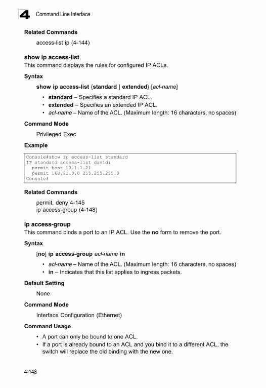
Command Line Interface4
Related Commandsaccess-list ip (4-144)
show ip access-list This command displays the rules for configured IP ACLs.
Syntax
show ip access-list {standard | extended} [acl-name]
• standard – Specifies a standard IP ACL.• extended – Specifies an extended IP ACL.• acl-name – Name of the ACL. (Maximum length: 16 characters, no spaces)
Command Mode
Privileged Exec
Example
Related Commands
permit, deny 4-145ip access-group (4-148)
ip access-group This command binds a port to an IP ACL. Use the no form to remove the port.
Syntax
[no] ip access-group acl-name in
• acl-name – Name of the ACL. (Maximum length: 16 characters, no spaces)• in – Indicates that this list applies to ingress packets.
Default Setting
None
Command Mode
Interface Configuration (Ethernet)
Command Usage
• A port can only be bound to one ACL.• If a port is already bound to an ACL and you bind it to a different ACL, the
switch will replace the old binding with the new one.
Console#show ip access-list standardIP standard access-list david: permit host 10.1.1.21 permit 168.92.0.0 255.255.255.0Console#
4-148
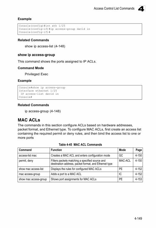
Access Control List Commands 4
ExampleRelated Commands
show ip access-list (4-148)
show ip access-group
This command shows the ports assigned to IP ACLs.
Command Mode
Privileged Exec
Example
Related Commands
ip access-group (4-148)
MAC ACLsThe commands in this section configure ACLs based on hardware addresses, packet format, and Ethernet type. To configure MAC ACLs, first create an access list containing the required permit or deny rules, and then bind the access list to one or more ports
Console(config)#int eth 1/25Console(config-if)#ip access-group david inConsole(config-if)#
Console#show ip access-groupInterface ethernet 1/25 IP access-list david inConsole#
Table 4-45 MAC ACL Commands
Command Function Mode Page
access-list mac Creates a MAC ACL and enters configuration mode GC 4-150
permit, deny Filters packets matching a specified source and destination address, packet format, and Ethernet type
MAC-ACL 4-150
show mac access-list Displays the rules for configured MAC ACLs PE 4-152
mac access-group Adds a port to a MAC ACL IC 4-152
show mac access-group Shows port assignments for MAC ACLs PE 4-153
4-149
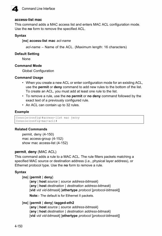
Command Line Interface4
access-list mac This command adds a MAC access list and enters MAC ACL configuration mode. Use the no form to remove the specified ACL.Syntax
[no] access-list mac acl-name
acl-name – Name of the ACL. (Maximum length: 16 characters)
Default Setting
None
Command Mode
Global Configuration
Command Usage
• When you create a new ACL or enter configuration mode for an existing ACL, use the permit or deny command to add new rules to the bottom of the list. To create an ACL, you must add at least one rule to the list.
• To remove a rule, use the no permit or no deny command followed by the exact text of a previously configured rule.
• An ACL can contain up to 32 rules.
Example
Related Commands
permit, deny (4-150)mac access-group (4-152)show mac access-list (4-152)
permit, deny (MAC ACL)This command adds a rule to a MAC ACL. The rule filters packets matching a specified MAC source or destination address (i.e., physical layer address), or Ethernet protocol type. Use the no form to remove a rule.
Syntax
[no] {permit | deny}{any | host source | source address-bitmask} {any | host destination | destination address-bitmask}[vid vid vid-bitmask] [ethertype protocol [protocol-bitmask]]
Note:- The default is for Ethernet II packets.
[no] {permit | deny} tagged-eth2 {any | host source | source address-bitmask} {any | host destination | destination address-bitmask}[vid vid vid-bitmask] [ethertype protocol [protocol-bitmask]]
Console(config)#access-list mac jerryConsole(config-mac-acl)#
4-150
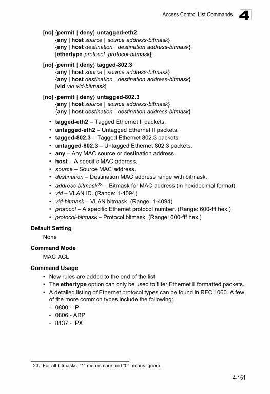
Access Control List Commands 4
[no] {permit | deny} untagged-eth2{any | host source | source address-bitmask} {any | host destination | destination address-bitmask}[ethertype protocol [protocol-bitmask]]
[no] {permit | deny} tagged-802.3 {any | host source | source address-bitmask} {any | host destination | destination address-bitmask}[vid vid vid-bitmask]
[no] {permit | deny} untagged-802.3 {any | host source | source address-bitmask} {any | host destination | destination address-bitmask}
• tagged-eth2 – Tagged Ethernet II packets.• untagged-eth2 – Untagged Ethernet II packets.• tagged-802.3 – Tagged Ethernet 802.3 packets.• untagged-802.3 – Untagged Ethernet 802.3 packets.• any – Any MAC source or destination address. • host – A specific MAC address.• source – Source MAC address.• destination – Destination MAC address range with bitmask.
• address-bitmask23 – Bitmask for MAC address (in hexidecimal format).• vid – VLAN ID. (Range: 1-4094)• vid-bitmask – VLAN bitmask. (Range: 1-4094)• protocol – A specific Ethernet protocol number. (Range: 600-fff hex.)• protocol-bitmask – Protocol bitmask. (Range: 600-fff hex.)
Default Setting
None
Command Mode
MAC ACL
Command Usage
• New rules are added to the end of the list.• The ethertype option can only be used to filter Ethernet II formatted packets. • A detailed listing of Ethernet protocol types can be found in RFC 1060. A few
of the more common types include the following:- 0800 - IP- 0806 - ARP- 8137 - IPX
23. For all bitmasks, “1” means care and “0” means ignore.
4-151
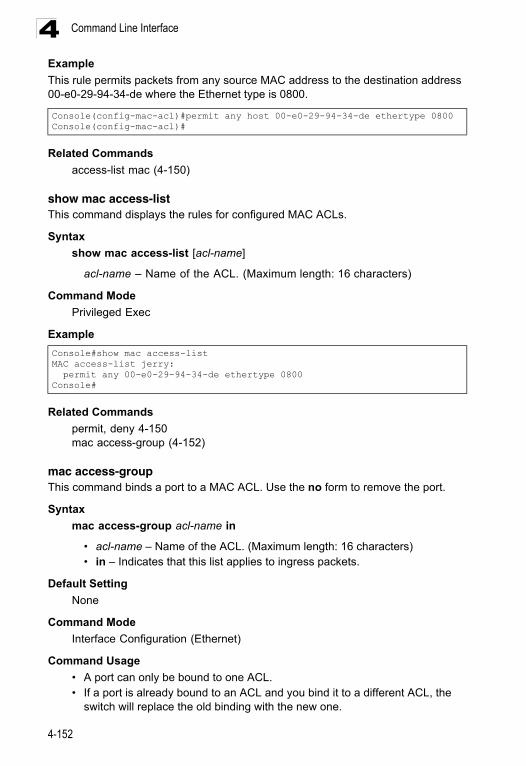
Command Line Interface4
ExampleThis rule permits packets from any source MAC address to the destination address 00-e0-29-94-34-de where the Ethernet type is 0800.
Related Commands
access-list mac (4-150)
show mac access-list This command displays the rules for configured MAC ACLs.
Syntax
show mac access-list [acl-name]
acl-name – Name of the ACL. (Maximum length: 16 characters)
Command Mode
Privileged Exec
Example
Related Commands
permit, deny 4-150mac access-group (4-152)
mac access-groupThis command binds a port to a MAC ACL. Use the no form to remove the port.
Syntax
mac access-group acl-name in
• acl-name – Name of the ACL. (Maximum length: 16 characters)• in – Indicates that this list applies to ingress packets.
Default Setting
None
Command Mode
Interface Configuration (Ethernet)
Command Usage
• A port can only be bound to one ACL.• If a port is already bound to an ACL and you bind it to a different ACL, the
switch will replace the old binding with the new one.
Console(config-mac-acl)#permit any host 00-e0-29-94-34-de ethertype 0800Console(config-mac-acl)#
Console#show mac access-listMAC access-list jerry: permit any 00-e0-29-94-34-de ethertype 0800Console#
4-152
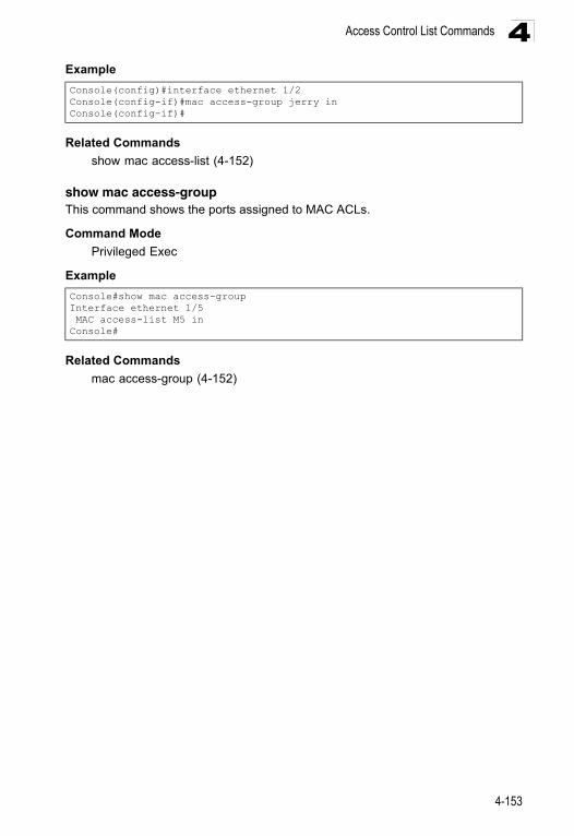
Access Control List Commands 4
ExampleRelated Commands
show mac access-list (4-152)
show mac access-groupThis command shows the ports assigned to MAC ACLs.
Command Mode
Privileged Exec
Example
Related Commands
mac access-group (4-152)
Console(config)#interface ethernet 1/2Console(config-if)#mac access-group jerry inConsole(config-if)#
Console#show mac access-groupInterface ethernet 1/5 MAC access-list M5 inConsole#
4-153
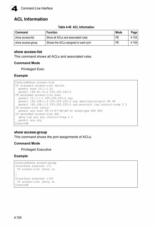
Command Line Interface4
ACL Informationshow access-listThis command shows all ACLs and associated rules.
Command Mode
Privileged Exec
Example
show access-groupThis command shows the port assignments of ACLs.
Command Mode
Privileged Executive
Example
Table 4-46 ACL Information
Command Function Mode Page
show access-list Show all ACLs and associated rules PE 4-154
show access-group Shows the ACLs assigned to each port PE 4-154
Console#show access-listIP standard access-list david: permit host 10.1.1.21 permit 168.92.16.0 255.255.240.0IP extended access-list bob: permit 10.7.1.1 255.255.255.0 any permit 192.168.1.0 255.255.255.0 any destination-port 80 80 permit 192.168.1.0 255.255.255.0 any protocol tcp control-code 2 2IP access-list jerry: permit any host 00-13-F7-A8-AF-52 ethertype 800 800IP extended access-list A6: deny tcp any any control-flag 2 2 permit any anyConsole#
Console#show access-groupInterface ethernet 1/1 IP access-list jerry in...Interface ethernet 1/26 IP access-list jerry inConsole#
4-154
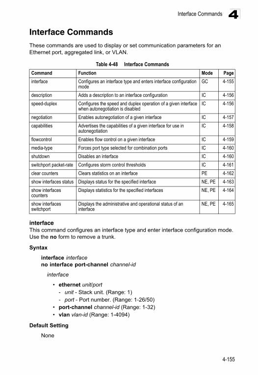
Interface Commands 4
Interface CommandsThese commands are used to display or set communication parameters for an Ethernet port, aggregated link, or VLAN.interfaceThis command configures an interface type and enter interface configuration mode. Use the no form to remove a trunk.
Syntax
interface interfaceno interface port-channel channel-id
interface
• ethernet unit/port- unit - Stack unit. (Range: 1) - port - Port number. (Range: 1-26/50)
• port-channel channel-id (Range: 1-32) • vlan vlan-id (Range: 1-4094)
Default Setting
None
Table 4-48 Interface Commands
Command Function Mode Page
interface Configures an interface type and enters interface configuration mode
GC 4-155
description Adds a description to an interface configuration IC 4-156
speed-duplex Configures the speed and duplex operation of a given interface when autonegotiation is disabled
IC 4-156
negotiation Enables autonegotiation of a given interface IC 4-157
capabilities Advertises the capabilities of a given interface for use in autonegotiation
IC 4-158
flowcontrol Enables flow control on a given interface IC 4-159
media-type Forces port type selected for combination ports IC 4-160
shutdown Disables an interface IC 4-160
switchport packet-rate Configures storm control thresholds IC 4-161
clear counters Clears statistics on an interface PE 4-162
show interfaces status Displays status for the specified interface NE, PE 4-163
show interfaces counters
Displays statistics for the specified interfaces NE, PE 4-164
show interfaces switchport
Displays the administrative and operational status of an interface
NE, PE 4-165
4-155
Command Line Interface4
Command ModeGlobal Configuration
Example
To specify port 24, enter the following command:
descriptionThis command adds a description to an interface. Use the no form to remove the description.
Syntax
description stringno description
string - Comment or a description to help you remember what is attached to this interface. (Range: 1-64 characters)
Default Setting
None
Command Mode
Interface Configuration (Ethernet, Port Channel)
Example
The following example adds a description to port 24.
speed-duplexThis command configures the speed and duplex mode of a given interface when autonegotiation is disabled. Use the no form to restore the default.
Syntax
speed-duplex {1000full | 100full | 100half | 10full | 10half}no speed-duplex
• 1000full - Forces 1000 Mbps full-duplex operation • 100full - Forces 100 Mbps full-duplex operation • 100half - Forces 100 Mbps half-duplex operation • 10full - Forces 10 Mbps full-duplex operation • 10half - Forces 10 Mbps half-duplex operation
Console(config)#interface ethernet 1/24Console(config-if)#
Console(config)#interface ethernet 1/24Console(config-if)#description RD-SW#3Console(config-if)#
4-156
Interface Commands 4
Default Setting• Auto-negotiation is enabled by default. • When auto-negotiation is disabled, the default speed-duplex setting is 100half
for 100BASE-TX ports and 1000full for Gigabit Ethernet ports.
Command Mode
Interface Configuration (Ethernet, Port Channel)
Command Usage
• The 1000BASE-T standard does not support forced mode. Auto-negotiation should always be used to establish a connection over any 1000BASE-T port or trunk. If not used, the success of the link process cannot be guaranteed when connecting to other types of switches.
• To force operation to the speed and duplex mode specified in a speed-duplex command, use the no negotiation command to disable auto-negotiation on the selected interface.
• When using the negotiation command to enable auto-negotiation, the optimal settings will be determined by the capabilities command. To set the speed/duplex mode under auto-negotiation, the required mode must be specified in the capabilities list for an interface.
Example
The following example configures port 5 to 100 Mbps, half-duplex operation.
Related Commands
negotiation (4-157)capabilities (4-158)
negotiationThis command enables autonegotiation for a given interface. Use the no form to disable autonegotiation.
Syntax
[no] negotiation
Default Setting
Enabled
Command Mode
Interface Configuration (Ethernet, Port Channel)
Console(config)#interface ethernet 1/5Console(config-if)#speed-duplex 100halfConsole(config-if)#no negotiationConsole(config-if)#
4-157
Command Line Interface4
Command Usage• When auto-negotiation is enabled the switch will negotiate the best settings for a link based on the capabilities command. When auto-negotiation is disabled, you must manually specify the link attributes with the speed-duplex and flowcontrol commands.
• If autonegotiation is disabled, auto-MDI/MDI-X pin signal configuration will also be disabled for the RJ-45 ports.
Example
The following example configures port 11 to use autonegotiation.
Related Commands
capabilities (4-158)speed-duplex (4-156)
capabilitiesThis command advertises the port capabilities of a given interface during autonegotiation. Use the no form with parameters to remove an advertised capability, or the no form without parameters to restore the default values.
Syntax
[no] capabilities {1000full | 100full | 100half | 10full | 10half | flowcontrol | symmetric}
• 1000full - Supports 1000 Mbps full-duplex operation • 100full - Supports 100 Mbps full-duplex operation • 100half - Supports 100 Mbps half-duplex operation • 10full - Supports 10 Mbps full-duplex operation • 10half - Supports 10 Mbps half-duplex operation • flowcontrol - Supports flow control • symmetric (Gigabit only) - When specified, the port transmits and receives
pause frames; when not specified, the port will auto-negotiate to determine the sender and receiver for asymmetric pause frames. (The current switch ASIC only supports symmetric pause frames.)
Default Setting
• 100BASE-TX: 10half, 10full, 100half, 100full• 1000BASE-T: 10half, 10full, 100half, 100full, 1000full• SFP: 1000full
Command Mode
Interface Configuration (Ethernet, Port Channel)
Console(config)#interface ethernet 1/11Console(config-if)#negotiationConsole(config-if)#
4-158
Interface Commands 4
Command UsageWhen auto-negotiation is enabled with the negotiation command, the switch will negotiate the best settings for a link based on the capabilites command. When auto-negotiation is disabled, you must manually specify the link attributes with the speed-duplex and flowcontrol commands.
Example
The following example configures Ethernet port 5 capabilities to 100half, 100full and flow control.
Related Commands
negotiation (4-157)speed-duplex (4-156)flowcontrol (4-159)
flowcontrolThis command enables flow control. Use the no form to disable flow control.
Syntax
[no] flowcontrol
Default Setting
Disabled
Command Mode
Interface Configuration (Ethernet, Port Channel)
Command Usage
• Flow control can eliminate frame loss by “blocking” traffic from end stations or segments connected directly to the switch when its buffers fill. When enabled, back pressure is used for half-duplex operation and IEEE 802.3-2005 (formally IEEE 802.3x) for full-duplex operation.
• To force flow control on or off (with the flowcontrol or no flowcontrol command), use the no negotiation command to disable auto-negotiation on the selected interface.
• When using the negotiation command to enable auto-negotiation, the optimal settings will be determined by the capabilities command. To enable flow control under auto-negotiation, “flowcontrol” must be included in the capabilities list for any port
Console(config)#interface ethernet 1/5Console(config-if)#capabilities 100halfConsole(config-if)#capabilities 100full Console(config-if)#capabilities flowcontrolConsole(config-if)#
4-159
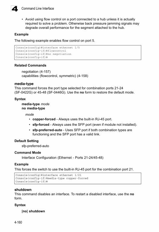
Command Line Interface4
• Avoid using flow control on a port connected to a hub unless it is actuallyrequired to solve a problem. Otherwise back pressure jamming signals may degrade overall performance for the segment attached to the hub.
Example
The following example enables flow control on port 5.
Related Commands
negotiation (4-157)capabilities (flowcontrol, symmetric) (4-158)
media-typeThis command forces the port type selected for combination ports 21-24 (SF-0422G) or 45-48 (SF-0446G). Use the no form to restore the default mode.
Syntax
media-type modeno media-type
mode • copper-forced - Always uses the built-in RJ-45 port.
• sfp-forced - Always uses the SFP port (even if module not installed).
• sfp-preferred-auto - Uses SFP port if both combination types are functioning and the SFP port has a valid link.
Default Setting
sfp-preferred-auto
Command Mode
Interface Configuration (Ethernet - Ports 21-24/45-48)
Example
This forces the switch to use the built-in RJ-45 port for the combination port 21.
shutdown This command disables an interface. To restart a disabled interface, use the no form.
Syntax
[no] shutdown
Console(config)#interface ethernet 1/5Console(config-if)#flowcontrolConsole(config-if)#no negotiation Console(config-if)#
Console(config)#interface ethernet 1/21Console(config-if)#media-type copper-forcedConsole(config-if)#
4-160
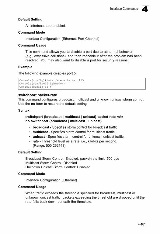
Interface Commands 4
Default SettingAll interfaces are enabled.
Command Mode
Interface Configuration (Ethernet, Port Channel)
Command Usage
This command allows you to disable a port due to abnormal behavior (e.g., excessive collisions), and then reenable it after the problem has been resolved. You may also want to disable a port for security reasons.
Example
The following example disables port 5.
switchport packet-rateThis command configures broadcast, multicast and unknown unicast storm control. Use the no form to restore the default setting.
Syntax
switchport {broadcast | multicast | unicast} packet-rate rateno switchport {broadcast | multicast | unicast}
• broadcast - Specifies storm control for broadcast traffic.• multicast - Specifies storm control for multicast traffic.• unicast - Specifies storm control for unknown unicast traffic.• rate - Threshold level as a rate; i.e., kilobits per second.
(Range: 500-262143)
Default Setting
Broadcast Storm Control: Enabled, packet-rate limit: 500 pps Multicast Storm Control: Disabled Unknown Unicast Storm Control: Disabled
Command Mode
Interface Configuration (Ethernet)
Command Usage
When traffic exceeds the threshold specified for broadcast, multicast or unknown unicast traffic, packets exceeding the threshold are dropped until the rate falls back down beneath the threshold.
Console(config)#interface ethernet 1/5Console(config-if)#shutdownConsole(config-if)#
4-161
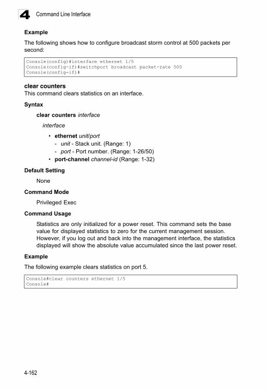
Command Line Interface4
ExampleThe following shows how to configure broadcast storm control at 500 packets per second:
clear countersThis command clears statistics on an interface.
Syntax
clear counters interface
interface
• ethernet unit/port- unit - Stack unit. (Range: 1) - port - Port number. (Range: 1-26/50)
• port-channel channel-id (Range: 1-32)
Default Setting
None
Command Mode
Privileged Exec
Command Usage
Statistics are only initialized for a power reset. This command sets the base value for displayed statistics to zero for the current management session. However, if you log out and back into the management interface, the statistics displayed will show the absolute value accumulated since the last power reset.
Example
The following example clears statistics on port 5.
Console(config)#interface ethernet 1/5Console(config-if)#switchport broadcast packet-rate 500Console(config-if)#
Console#clear counters ethernet 1/5Console#
4-162
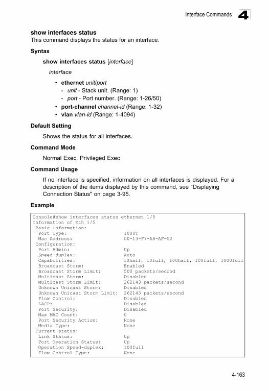
Interface Commands 4
show interfaces statusThis command displays the status for an interface.Syntax
show interfaces status [interface]
interface
• ethernet unit/port- unit - Stack unit. (Range: 1) - port - Port number. (Range: 1-26/50)
• port-channel channel-id (Range: 1-32) • vlan vlan-id (Range: 1-4094)
Default Setting
Shows the status for all interfaces.
Command Mode
Normal Exec, Privileged Exec
Command Usage
If no interface is specified, information on all interfaces is displayed. For a description of the items displayed by this command, see "Displaying Connection Status" on page 3-95.
Example
Console#show interfaces status ethernet 1/5Information of Eth 1/5 Basic information: Port Type: 1000T Mac Address: 00-13-F7-A8-AF-52 Configuration: Port Admin: Up Speed-duplex: Auto Capabilities: 10half, 10full, 100half, 100full, 1000full Broadcast Storm: Enabled Broadcast Storm Limit: 500 packets/second Multicast Storm: Disabled Multicast Storm Limit: 262143 packets/second Unknown Unicast Storm: Disabled Unknown Unicast Storm Limit: 262143 packets/second Flow Control: Disabled LACP: Disabled Port Security: Disabled Max MAC Count: 0 Port Security Action: None Media Type: None Current status: Link Status: Up Port Operation Status: Up Operation Speed-duplex: 100full Flow Control Type: None
4-163
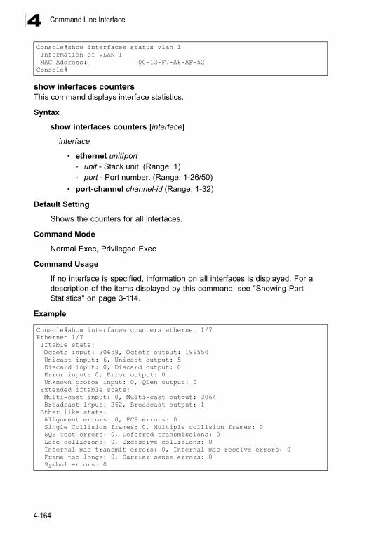
Command Line Interface4
show interfaces countersThis command displays interface statistics.
Syntax
show interfaces counters [interface]
interface
• ethernet unit/port- unit - Stack unit. (Range: 1) - port - Port number. (Range: 1-26/50)
• port-channel channel-id (Range: 1-32)
Default Setting
Shows the counters for all interfaces.
Command Mode
Normal Exec, Privileged Exec
Command Usage
If no interface is specified, information on all interfaces is displayed. For a description of the items displayed by this command, see "Showing Port Statistics" on page 3-114.
Example
Console#show interfaces status vlan 1 Information of VLAN 1 MAC Address: 00-13-F7-A8-AF-52Console#
Console#show interfaces counters ethernet 1/7Ethernet 1/7 Iftable stats: Octets input: 30658, Octets output: 196550 Unicast input: 6, Unicast output: 5 Discard input: 0, Discard output: 0 Error input: 0, Error output: 0 Unknown protos input: 0, QLen output: 0 Extended iftable stats: Multi-cast input: 0, Multi-cast output: 3064 Broadcast input: 262, Broadcast output: 1 Ether-like stats: Alignment errors: 0, FCS errors: 0 Single Collision frames: 0, Multiple collision frames: 0 SQE Test errors: 0, Deferred transmissions: 0 Late collisions: 0, Excessive collisions: 0 Internal mac transmit errors: 0, Internal mac receive errors: 0 Frame too longs: 0, Carrier sense errors: 0 Symbol errors: 0
4-164
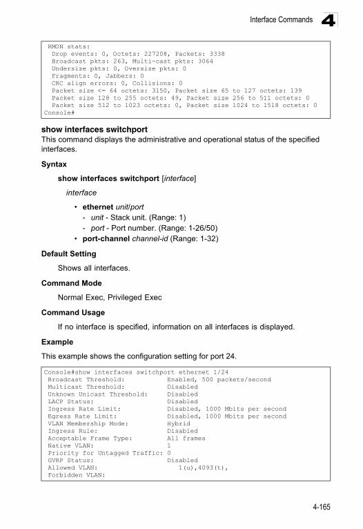
Interface Commands 4
show interfaces switchportThis command displays the administrative and operational status of the specified interfaces.
Syntax
show interfaces switchport [interface]
interface
• ethernet unit/port- unit - Stack unit. (Range: 1) - port - Port number. (Range: 1-26/50)
• port-channel channel-id (Range: 1-32)
Default Setting
Shows all interfaces.
Command Mode
Normal Exec, Privileged Exec
Command Usage
If no interface is specified, information on all interfaces is displayed.
Example
This example shows the configuration setting for port 24.
RMON stats: Drop events: 0, Octets: 227208, Packets: 3338 Broadcast pkts: 263, Multi-cast pkts: 3064 Undersize pkts: 0, Oversize pkts: 0 Fragments: 0, Jabbers: 0 CRC align errors: 0, Collisions: 0 Packet size <= 64 octets: 3150, Packet size 65 to 127 octets: 139 Packet size 128 to 255 octets: 49, Packet size 256 to 511 octets: 0 Packet size 512 to 1023 octets: 0, Packet size 1024 to 1518 octets: 0Console#
Console#show interfaces switchport ethernet 1/24 Broadcast Threshold: Enabled, 500 packets/second Multicast Threshold: Disabled Unknown Unicast Threshold: Disabled LACP Status: Disabled Ingress Rate Limit: Disabled, 1000 Mbits per second Egress Rate Limit: Disabled, 1000 Mbits per second VLAN Membership Mode: Hybrid Ingress Rule: Disabled Acceptable Frame Type: All frames Native VLAN: 1 Priority for Untagged Traffic: 0 GVRP Status: Disabled Allowed VLAN: 1(u),4093(t), Forbidden VLAN:
4-165
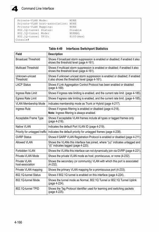
Command Line Interface4
Private-VLAN Mode: NONE Private-VLAN host-association: NONE Private-VLAN Mapping: NONE 802.1Q-tunnel Status: Disable 802.1Q-tunnel Mode: NORMAL 802.1Q-tunnel TPID: 8100(Hex)Console#Table 4-49 Interfaces Switchport Statistics
Field Description
Broadcast Threshold Shows if broadcast storm suppression is enabled or disabled; if enabled it also shows the threshold level (page 4-161).
Multicast Threshold Shows if multicast storm suppression is enabled or disabled; if enabled it also shows the threshold level (page 4-161).
Unknown-unicast Threshold
Shows if unknown unicast storm suppression is enabled or disabled; if enabled it also shows the threshold level (page 4-161).
LACP Status Shows if Link Aggregation Control Protocol has been enabled or disabled (page 4-169).
Ingress Rate Limit Shows if ingress rate limiting is enabled, and the current rate limit. (page 4-185).
Egress Rate Limit Shows if egress rate limiting is enabled, and the current rate limit. (page 4-185).
VLAN Membership Mode Indicates membership mode as Trunk or Hybrid (page 4-217).
Ingress Rule Shows if ingress filtering is enabled or disabled (page 4-218).Note: Ingress filtering is always enabled.
Acceptable Frame Type Shows if acceptable VLAN frames include all types or tagged frames only (page 4-218).
Native VLAN Indicates the default Port VLAN ID (page 4-219).
Priority for untagged traffic Indicates the default priority for untagged frames (page 4-238).
GVRP Status Shows if GARP VLAN Registration Protocol is enabled or disabled (page 4-211).
Allowed VLAN Shows the VLANs this interface has joined, where “(u)” indicates untagged and “(t)” indicates tagged (page 4-220).
Forbidden VLAN Shows the VLANs this interface can not dynamically join via GVRP (page 4-221).
Private-VLAN Mode Shows the private VLAN mode as host, promiscuous, or none (4-232).
Private VLAN host-association
Shows the secondary (or community) VLAN with which this port is associated (4-232).
Private VLAN mapping Shows the primary VLAN mapping for a promiscuous port (4-233).
802.1Q-tunnel Status Shows if 802.1Q tunnel is enabled on this interface (page 4-224).
802.1Q-tunnel Mode Shows the tunnel mode as Normal, 802.1Q Tunnel or 802.1Q Tunnel Uplink (page 4-224).
802.1Q-tunnel TPID Shows the Tag Protocol Identifier used for learning and switching packets (page 4-225).
4-166
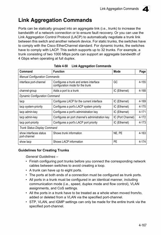
Link Aggregation Commands 4
Link Aggregation CommandsPorts can be statically grouped into an aggregate link (i.e., trunk) to increase the bandwidth of a network connection or to ensure fault recovery. Or you can use the Link Aggregation Control Protocol (LACP) to automatically negotiate a trunk link between this switch and another network device. For static trunks, the switches have to comply with the Cisco EtherChannel standard. For dynamic trunks, the switches have to comply with LACP. This switch supports up to 32 trunks. For example, a trunk consisting of two 1000 Mbps ports can support an aggregate bandwidth of 4 Gbps when operating at full duplex.Guidelines for Creating Trunks
General Guidelines –• Finish configuring port trunks before you connect the corresponding network
cables between switches to avoid creating a loop.• A trunk can have up to eight ports.• The ports at both ends of a connection must be configured as trunk ports.• All ports in a trunk must be configured in an identical manner, including
communication mode (i.e., speed, duplex mode and flow control), VLAN assignments, and CoS settings.
• All the ports in a trunk have to be treated as a whole when moved from/to, added or deleted from a VLAN via the specified port-channel.
• STP, VLAN, and IGMP settings can only be made for the entire trunk via the specified port-channel.
Table 4-50 Link Aggregation Commands
Command Function Mode Page
Manual Configuration Commands
interface port-channel Configures a trunk and enters interface configuration mode for the trunk
GC 4-155
channel-group Adds a port to a trunk IC (Ethernet) 4-168
Dynamic Configuration Command
lacp Configures LACP for the current interface IC (Ethernet) 4-169
lacp system-priority Configures a port's LACP system priority IC (Ethernet) 4-170
lacp admin-key Configures a port's administration key IC (Ethernet) 4-171
lacp admin-key Configures an port channel’s administration key IC (Port Channel) 4-172
lacp port-priority Configures a port's LACP port priority IC (Ethernet) 4-173
Trunk Status Display Command
show interfaces status port-channel
Shows trunk information NE, PE 4-163
show lacp Shows LACP information PE 4-174
4-167
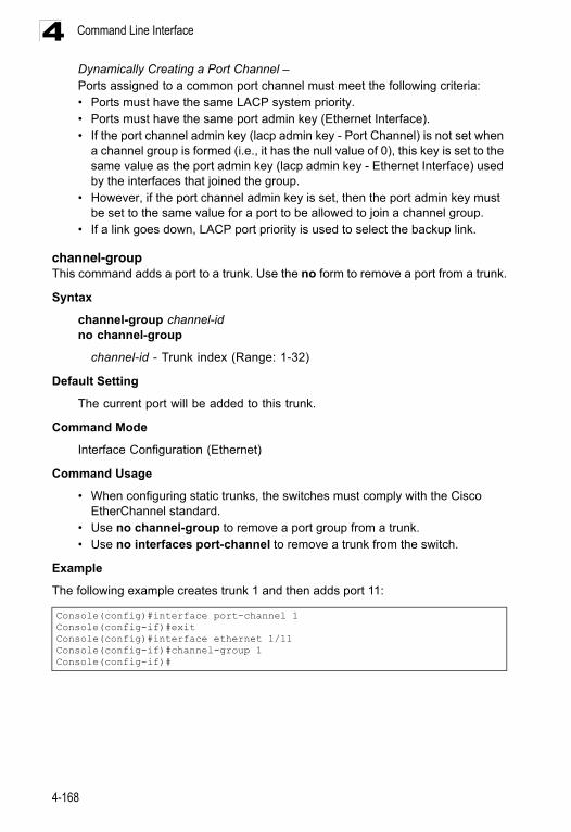
Command Line Interface4
Dynamically Creating a Port Channel –Ports assigned to a common port channel must meet the following criteria:• Ports must have the same LACP system priority.• Ports must have the same port admin key (Ethernet Interface).• If the port channel admin key (lacp admin key - Port Channel) is not set whena channel group is formed (i.e., it has the null value of 0), this key is set to the same value as the port admin key (lacp admin key - Ethernet Interface) used by the interfaces that joined the group.
• However, if the port channel admin key is set, then the port admin key must be set to the same value for a port to be allowed to join a channel group.
• If a link goes down, LACP port priority is used to select the backup link.
channel-group This command adds a port to a trunk. Use the no form to remove a port from a trunk.
Syntax
channel-group channel-idno channel-group
channel-id - Trunk index (Range: 1-32)
Default Setting
The current port will be added to this trunk.
Command Mode
Interface Configuration (Ethernet)
Command Usage
• When configuring static trunks, the switches must comply with the Cisco EtherChannel standard.
• Use no channel-group to remove a port group from a trunk.• Use no interfaces port-channel to remove a trunk from the switch.
Example
The following example creates trunk 1 and then adds port 11:
Console(config)#interface port-channel 1Console(config-if)#exitConsole(config)#interface ethernet 1/11Console(config-if)#channel-group 1Console(config-if)#
4-168
Link Aggregation Commands 4
lacpThis command enables 802.3ad Link Aggregation Control Protocol (LACP) for the current interface. Use the no form to disable it.Syntax
[no] lacp
Default Setting
Disabled
Command Mode
Interface Configuration (Ethernet)
Command Usage
• The ports on both ends of an LACP trunk must be configured for full duplex, and auto-negotiation.
• A trunk formed with another switch using LACP will automatically be assigned the next available port-channel ID.
• If the target switch has also enabled LACP on the connected ports, the trunk will be activated automatically.
• If more than eight ports attached to the same target switch have LACP enabled, the additional ports will be placed in standby mode, and will only be enabled if one of the active links fails.
4-169
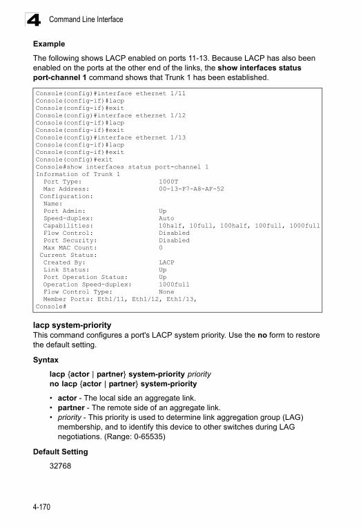
Command Line Interface4
ExampleThe following shows LACP enabled on ports 11-13. Because LACP has also been enabled on the ports at the other end of the links, the show interfaces status port-channel 1 command shows that Trunk 1 has been established.
lacp system-priorityThis command configures a port's LACP system priority. Use the no form to restore the default setting.
Syntax
lacp {actor | partner} system-priority priorityno lacp {actor | partner} system-priority
• actor - The local side an aggregate link.• partner - The remote side of an aggregate link.• priority - This priority is used to determine link aggregation group (LAG)
membership, and to identify this device to other switches during LAG negotiations. (Range: 0-65535)
Default Setting
32768
Console(config)#interface ethernet 1/11Console(config-if)#lacpConsole(config-if)#exitConsole(config)#interface ethernet 1/12Console(config-if)#lacpConsole(config-if)#exitConsole(config)#interface ethernet 1/13Console(config-if)#lacpConsole(config-if)#exitConsole(config)#exitConsole#show interfaces status port-channel 1Information of Trunk 1 Port Type: 1000T Mac Address: 00-13-F7-A8-AF-52 Configuration: Name: Port Admin: Up Speed-duplex: Auto Capabilities: 10half, 10full, 100half, 100full, 1000full Flow Control: Disabled Port Security: Disabled Max MAC Count: 0 Current Status: Created By: LACP Link Status: Up Port Operation Status: Up Operation Speed-duplex: 1000full Flow Control Type: None Member Ports: Eth1/11, Eth1/12, Eth1/13,Console#
4-170
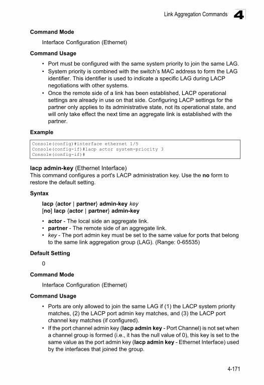
Link Aggregation Commands 4
Command ModeInterface Configuration (Ethernet)
Command Usage
• Port must be configured with the same system priority to join the same LAG.• System priority is combined with the switch’s MAC address to form the LAG
identifier. This identifier is used to indicate a specific LAG during LACP negotiations with other systems.
• Once the remote side of a link has been established, LACP operational settings are already in use on that side. Configuring LACP settings for the partner only applies to its administrative state, not its operational state, and will only take effect the next time an aggregate link is established with the partner.
Example
lacp admin-key (Ethernet Interface)This command configures a port's LACP administration key. Use the no form to restore the default setting.
Syntax
lacp {actor | partner} admin-key key[no] lacp {actor | partner} admin-key
• actor - The local side an aggregate link.• partner - The remote side of an aggregate link.• key - The port admin key must be set to the same value for ports that belong
to the same link aggregation group (LAG). (Range: 0-65535)
Default Setting
0
Command Mode
Interface Configuration (Ethernet)
Command Usage
• Ports are only allowed to join the same LAG if (1) the LACP system priority matches, (2) the LACP port admin key matches, and (3) the LACP port channel key matches (if configured).
• If the port channel admin key (lacp admin key - Port Channel) is not set when a channel group is formed (i.e., it has the null value of 0), this key is set to the same value as the port admin key (lacp admin key - Ethernet Interface) used by the interfaces that joined the group.
Console(config)#interface ethernet 1/5Console(config-if)#lacp actor system-priority 3Console(config-if)#
4-171
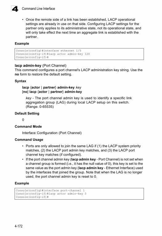
Command Line Interface4
• Once the remote side of a link has been established, LACP operationalsettings are already in use on that side. Configuring LACP settings for the partner only applies to its administrative state, not its operational state, and will only take effect the next time an aggregate link is established with the partner.
Example
lacp admin-key (Port Channel)This command configures a port channel's LACP administration key string. Use the no form to restore the default setting.
Syntax
lacp {actor | partner} admin-key key[no] lacp {actor | partner} admin-key
key - The port channel admin key is used to identify a specific link aggregation group (LAG) during local LACP setup on this switch. (Range: 0-65535)
Default Setting
0
Command Mode
Interface Configuration (Port Channel)
Command Usage
• Ports are only allowed to join the same LAG if (1) the LACP system priority matches, (2) the LACP port admin key matches, and (3) the LACP port channel key matches (if configured).
• If the port channel admin key (lacp admin key - Port Channel) is not set when a channel group is formed (i.e., it has the null value of 0), this key is set to the same value as the port admin key (lacp admin key - Ethernet Interface) used by the interfaces that joined the group. Note that when the LAG is no longer used, the port channel admin key is reset to 0.
Example
Console(config)#interface ethernet 1/5Console(config-if)#lacp actor admin-key 120Console(config-if)#
Console(config)#interface port-channel 1Console(config-if)#lacp actor admin-key 3Console(config-if)#
4-172
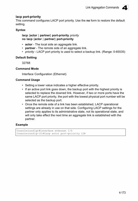
Link Aggregation Commands 4
lacp port-priorityThis command configures LACP port priority. Use the no form to restore the default setting.Syntax
lacp {actor | partner} port-priority priorityno lacp {actor | partner} port-priority
• actor - The local side an aggregate link.• partner - The remote side of an aggregate link.• priority - LACP port priority is used to select a backup link. (Range: 0-65535)
Default Setting
32768
Command Mode
Interface Configuration (Ethernet)
Command Usage
• Setting a lower value indicates a higher effective priority.• If an active port link goes down, the backup port with the highest priority is
selected to replace the downed link. However, if two or more ports have the same LACP port priority, the port with the lowest physical port number will be selected as the backup port.
• Once the remote side of a link has been established, LACP operational settings are already in use on that side. Configuring LACP settings for the partner only applies to its administrative state, not its operational state, and will only take effect the next time an aggregate link is established with the partner.
Example
Console(config)#interface ethernet 1/5Console(config-if)#lacp actor port-priority 128
4-173
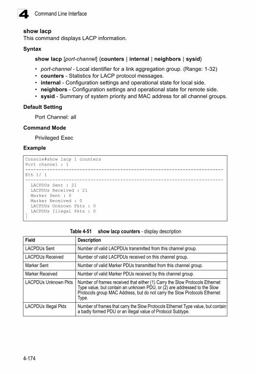
Command Line Interface4
show lacpThis command displays LACP information.Syntax
show lacp [port-channel] {counters | internal | neighbors | sysid}
• port-channel - Local identifier for a link aggregation group. (Range: 1-32)• counters - Statistics for LACP protocol messages. • internal - Configuration settings and operational state for local side.• neighbors - Configuration settings and operational state for remote side.• sysid - Summary of system priority and MAC address for all channel groups.
Default Setting
Port Channel: all
Command Mode
Privileged Exec
Example
Console#show lacp 1 countersPort channel : 1 -------------------------------------------------------------------------Eth 1/ 1 ------------------------------------------------------------------------- LACPDUs Sent : 21 LACPDUs Received : 21 Marker Sent : 0 Marker Received : 0 LACPDUs Unknown Pkts : 0 LACPDUs Illegal Pkts : 0...
Table 4-51 show lacp counters - display description
Field Description
LACPDUs Sent Number of valid LACPDUs transmitted from this channel group.
LACPDUs Received Number of valid LACPDUs received on this channel group.
Marker Sent Number of valid Marker PDUs transmitted from this channel group.
Marker Received Number of valid Marker PDUs received by this channel group.
LACPDUs Unknown Pkts Number of frames received that either (1) Carry the Slow Protocols Ethernet Type value, but contain an unknown PDU, or (2) are addressed to the Slow Protocols group MAC Address, but do not carry the Slow Protocols Ethernet Type.
LACPDUs Illegal Pkts Number of frames that carry the Slow Protocols Ethernet Type value, but contain a badly formed PDU or an illegal value of Protocol Subtype.
4-174
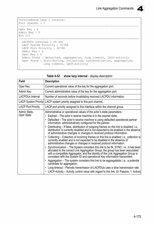
Link Aggregation Commands 4
Console#show lacp 1 internalPort channel : 1-------------------------------------------------------------------------Oper Key : 4Admin Key : 0Eth 1/1------------------------------------------------------------------------- LACPDUs Internal : 30 sec LACP System Priority : 32768 LACP Port Priority : 32768 Admin Key : 4 Oper Key : 4 Admin State : defaulted, aggregation, long timeout, LACP-activity Oper State : distributing, collecting, synchronization, aggregation, long timeout, LACP-activity...Table 4-52 show lacp internal - display description
Field Description
Oper Key Current operational value of the key for the aggregation port.
Admin Key Current administrative value of the key for the aggregation port.
LACPDUs Internal Number of seconds before invalidating received LACPDU information.
LACP System Priority LACP system priority assigned to this port channel.
LACP Port Priority LACP port priority assigned to this interface within the channel group.
Admin State,Oper State
Administrative or operational values of the actor’s state parameters:• Expired – The actor’s receive machine is in the expired state;• Defaulted – The actor’s receive machine is using defaulted operational partner
information, administratively configured for the partner.• Distributing – If false, distribution of outgoing frames on this link is disabled; i.e.,
distribution is currently disabled and is not expected to be enabled in the absence of administrative changes or changes in received protocol information.
• Collecting – Collection of incoming frames on this link is enabled; i.e., collection is currently enabled and is not expected to be disabled in the absence of administrative changes or changes in received protocol information.
• Synchronization – The System considers this link to be IN_SYNC; i.e., it has been allocated to the correct Link Aggregation Group, the group has been associated with a compatible Aggregator, and the identity of the Link Aggregation Group is consistent with the System ID and operational Key information transmitted.
• Aggregation – The system considers this link to be aggregatable; i.e., a potential candidate for aggregation.
• Long timeout – Periodic transmission of LACPDUs uses a slow transmission rate.• LACP-Activity – Activity control value with regard to this link. (0: Passive; 1: Active)
4-175
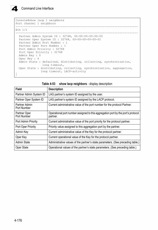
Command Line Interface4
Console#show lacp 1 neighborsPort channel 1 neighbors-------------------------------------------------------------------------Eth 1/1------------------------------------------------------------------------- Partner Admin System ID : 32768, 00-00-00-00-00-00 Partner Oper System ID : 32768, 00-00-00-00-00-01 Partner Admin Port Number : 1 Partner Oper Port Number : 1 Port Admin Priority : 32768 Port Oper Priority : 32768 Admin Key : 0 Oper Key : 4 Admin State : defaulted, distributing, collecting, synchronization, long timeout, Oper State : distributing, collecting, synchronization, aggregation, long timeout, LACP-activity...Table 4-53 show lacp neighbors - display description
Field Description
Partner Admin System ID LAG partner’s system ID assigned by the user.
Partner Oper System ID LAG partner’s system ID assigned by the LACP protocol.
Partner Admin Port Number
Current administrative value of the port number for the protocol Partner.
Partner Oper Port Number
Operational port number assigned to this aggregation port by the port’s protocol partner.
Port Admin Priority Current administrative value of the port priority for the protocol partner.
Port Oper Priority Priority value assigned to this aggregation port by the partner.
Admin Key Current administrative value of the Key for the protocol partner.
Oper Key Current operational value of the Key for the protocol partner.
Admin State Administrative values of the partner’s state parameters. (See preceding table.)
Oper State Operational values of the partner’s state parameters. (See preceding table.)
4-176
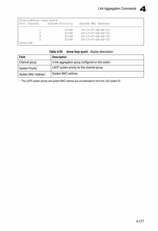
Link Aggregation Commands 4
Console#show lacp sysidPort Channel System Priority System MAC Address------------------------------------------------------------------------- 1 32768 00-13-F7-A8-AF-52 2 32768 00-13-F7-A8-AF-52 3 32768 00-13-F7-A8-AF-52 4 32768 00-13-F7-A8-AF-52Console#Table 4-54 show lacp sysid - display description
Field Description
Channel group A link aggregation group configured on this switch.
System Priority* LACP system priority for this channel group.
System MAC Address* System MAC address.
* The LACP system priority and system MAC address are concatenated to form the LAG system ID.
4-177
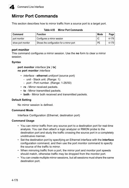
Command Line Interface4
Mirror Port CommandsThis section describes how to mirror traffic from a source port to a target port.
port monitorThis command configures a mirror session. Use the no form to clear a mirror session.
Syntax
port monitor interface [rx | tx]no port monitor interface
• interface - ethernet unit/port (source port) - unit - Stack unit. (Range: 1) - port - Port number. (Range: 1-26/50)
• rx - Mirror received packets. • tx - Mirror transmitted packets. • both - Mirror both received and transmitted packets.
Default Setting
No mirror session is defined.
Command Mode
Interface Configuration (Ethernet, destination port)
Command Usage
• You can mirror traffic from any source port to a destination port for real-time analysis. You can then attach a logic analyzer or RMON probe to the destination port and study the traffic crossing the source port in a completely unobtrusive manner.
• Set the destination port by specifying an Ethernet interface with the interface configuration command, and then use the port monitor command to specify the source of the traffic to mirror.
• When mirroring traffic from a port, the mirror port and monitor port speeds should match, otherwise traffic may be dropped from the monitor port.
• You can create multiple mirror sessions, but all sessions must share the same destination port.
Table 4-55 Mirror Port Commands
Command Function Mode Page
port monitor Configures a mirror session IC 4-178
show port monitor Shows the configuration for a mirror port PE 4-179
4-178
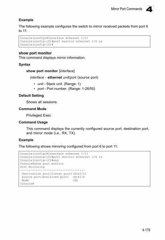
Mirror Port Commands 4
ExampleThe following example configures the switch to mirror received packets from port 6 to 11:
show port monitorThis command displays mirror information.
Syntax
show port monitor [interface]
interface - ethernet unit/port (source port)
• unit - Stack unit. (Range: 1) • port - Port number. (Range: 1-26/50)
Default Setting
Shows all sessions.
Command Mode
Privileged Exec
Command Usage
This command displays the currently configured source port, destination port, and mirror mode (i.e., RX, TX).
Example
The following shows mirroring configured from port 6 to port 11:
Console(config)#interface ethernet 1/11Console(config-if)#port monitor ethernet 1/6 rxConsole(config-if)#
Console(config)#interface ethernet 1/11Console(config-if)#port monitor ethernet 1/6 rxConsole(config-if)#endConsole#show port monitorPort Mirroring------------------------------------- Destination port(listen port):Eth1/11 Source port(monitored port) :Eth1/6 Mode :RXConsole#
4-179
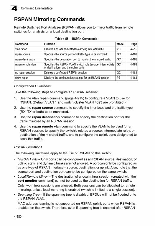
Command Line Interface4
RSPAN Mirroring CommandsRemote Switched Port Analyzer (RSPAN) allows you to mirror traffic from remote switches for analysis on a local destination port.Configuration Guidelines
Take the following steps to configure an RSPAN session:
1. Use the vlan rspan command (page 4-215) to configure a VLAN to use for RSPAN. (Default VLAN 1 and switch cluster VLAN 4093 are prohibited.)
2. Use the rspan source command to specify the interfaces and the traffic type (RX, TX or both) to be monitored.
3. Use the rspan destination command to specify the destination port for the traffic mirrored by an RSPAN session.
4. Use the rspan remote vlan command to specify the VLAN to be used for an RSPAN session, to specify the switch’s role as a source, intermediate relay, or destination of the mirrored traffic, and to configure the uplink ports designated to carry this traffic.
RSPAN Limitations
The following limitations apply to the use of RSPAN on this switch:
• RSPAN Ports – Only ports can be configured as an RSPAN source, destination, or uplink; static and dynamic trunks are not allowed. A port can only be configured as as one type of RSPAN interface – source, destination, or uplink. Also, note that the source port and destination port cannot be configured on the same switch.
• Local/Remote Mirror – The destination of a local mirror session (created with the port monitor command) cannot be used as the destination for RSPAN traffic.
Only two mirror sessions are allowed. Both sessions can be allocated to remote mirroring, unless local mirroring is enabled (which is limited to a single session).
• Spanning Tree – If the spanning tree is disabled, BPDUs will not be flooded onto the RSPAN VLAN.
MAC address learning is not supported on RSPAN uplink ports when RSPAN is enabled on the switch. Therefore, even if spanning tree is enabled after RSPAN
Table 4-56 RSPAN Commands
Command Function Mode Page
vlan rspan Creates a VLAN dedicated to carrying RSPAN traffic VC 4-215
rspan source Specifies the source port and traffic type to be mirrored GC 4-181
rspan destination Specifies the destination port to monitor the mirrored traffic GC 4-182
rspan remote vlan Specifies the RSPAN VLAN, switch role (source, intermediate or destination), and the uplink ports
GC 4-183
no rspan session Deletes a configured RSPAN session GC 4-184
show rspan Displays the configuration settings for an RSPAN session PE 4-184
4-180
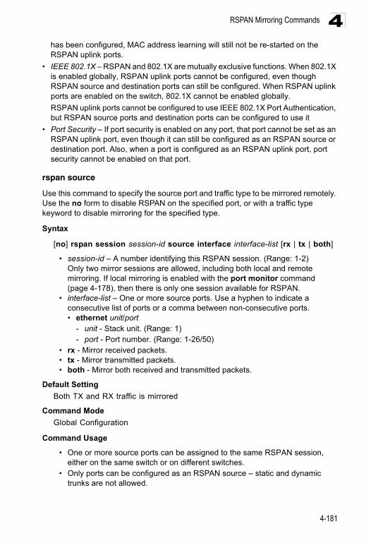
RSPAN Mirroring Commands 4
has been configured, MAC address learning will still not be re-started on the RSPAN uplink ports.• IEEE 802.1X – RSPAN and 802.1X are mutually exclusive functions. When 802.1X is enabled globally, RSPAN uplink ports cannot be configured, even though RSPAN source and destination ports can still be configured. When RSPAN uplink ports are enabled on the switch, 802.1X cannot be enabled globally.
RSPAN uplink ports cannot be configured to use IEEE 802.1X Port Authentication, but RSPAN source ports and destination ports can be configured to use it
• Port Security – If port security is enabled on any port, that port cannot be set as an RSPAN uplink port, even though it can still be configured as an RSPAN source or destination port. Also, when a port is configured as an RSPAN uplink port, port security cannot be enabled on that port.
rspan source
Use this command to specify the source port and traffic type to be mirrored remotely. Use the no form to disable RSPAN on the specified port, or with a traffic type keyword to disable mirroring for the specified type.
Syntax
[no] rspan session session-id source interface interface-list [rx | tx | both]
• session-id – A number identifying this RSPAN session. (Range: 1-2)Only two mirror sessions are allowed, including both local and remote mirroring. If local mirroring is enabled with the port monitor command (page 4-178), then there is only one session available for RSPAN.
• interface-list – One or more source ports. Use a hyphen to indicate a consecutive list of ports or a comma between non-consecutive ports. • ethernet unit/port
- unit - Stack unit. (Range: 1)- port - Port number. (Range: 1-26/50)
• rx - Mirror received packets. • tx - Mirror transmitted packets. • both - Mirror both received and transmitted packets.
Default Setting
Both TX and RX traffic is mirrored
Command Mode
Global Configuration
Command Usage
• One or more source ports can be assigned to the same RSPAN session, either on the same switch or on different switches.
• Only ports can be configured as an RSPAN source – static and dynamic trunks are not allowed.
4-181
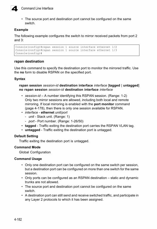
Command Line Interface4
• The source port and destination port cannot be configured on the sameswitch.
Example
The following example configures the switch to mirror received packets from port 2 and 3:
rspan destination
Use this command to specify the destination port to monitor the mirrored traffic. Use the no form to disable RSPAN on the specified port.
Syntax
rspan session session-id destination interface interface [tagged | untagged]no rspan session session-id destination interface interface
• session-id – A number identifying this RSPAN session. (Range: 1-2)Only two mirror sessions are allowed, including both local and remote mirroring. If local mirroring is enabled with the port monitor command (page 4-178), then there is only one session available for RSPAN.
• interface - ethernet unit/port- unit - Stack unit. (Range: 1)- port - Port number. (Range: 1-26/50)
• tagged - Traffic exiting the destination port carries the RSPAN VLAN tag. • untagged - Traffic exiting the destination port is untagged.
Default Setting
Traffic exiting the destination port is untagged.
Command Mode
Global Configuration
Command Usage
• Only one destination port can be configured on the same switch per session, but a destination port can be configured on more than one switch for the same session.
• Only ports can be configured as an RSPAN destination – static and dynamic trunks are not allowed.
• The source port and destination port cannot be configured on the same switch.
• A destination port can still send and receive switched traffic, and participate in any Layer 2 protocols to which it has been assigned.
Console(config)#rspan session 1 source interface ethernet 1/2Console(config)#rspan session 1 source interface ethernet 1/3Console(config)#
4-182
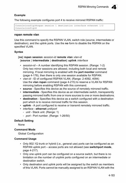
RSPAN Mirroring Commands 4
ExampleThe following example configures port 4 to receive mirrored RSPAN traffic:
rspan remote vlan
Use this command to specify the RSPAN VLAN, switch role (source, intermediate or destination), and the uplink ports. Use the no form to disable the RSPAN on the specified VLAN.
Syntax
[no] rspan session session-id remote vlan vlan-id {source | intermediate | destination} uplink interface
• session-id – A number identifying this RSPAN session. (Range: 1-2)Only two mirror sessions are allowed, including both local and remote mirroring. If local mirroring is enabled with the port monitor command (page 4-178), then there is only one session available for RSPAN.
• vlan-id - ID of configured RSPAN VLAN. (Range: 2-4092, 4094) Use the vlan rspan command (page 4-215) to reserve a VLAN for RSPAN mirroring before enabling RSPAN with this command.
• source - Specifies this device as the source of remotely mirrored traffic.• intermediate - Specifies this device as an intermediate switch, transparently
passing mirrored traffic from one or more sources to one or more destinations.• destination - Specifies this device as a switch configured with a destination
port which is to receive mirrored traffic for this session.• uplink - A port configured to receive or transmit remotely mirrored traffic.• interface - ethernet unit/port
- unit - Stack unit. (Range: 1)- port - Port number. (Range: 1-26/50)
Default Setting
None
Command Mode
Global Configuration
Command Usage
• Only 802.1Q trunk or hybrid (i.e., general use) ports can be configured as an RSPAN uplink port – access ports are not allowed (see switchport mode, page 4-217).
• Only one uplink port can be configured on a source switch, but there is no limitation on the number of unplink ports configured on an intermediate or destination switch.
• Only destination and uplink ports will be assigned by the switch as members of this VLAN. Ports cannot be manually assigned to an RSPAN VLAN with the
Console(config)#rspan session 1 destination interface ethernet 1/2Console(config)#
4-183
Command Line Interface4
switchport allowed vlan command (page 4-220). Nor can GVRP dynamically add port members to an RSPAN VLAN. Also, note that the show vlan command (page 4-222) will not display any members for an RSPAN VLAN, but will only show configured RSPAN VLAN identifiers.Example
The following example enables RSPAN on VLAN 2, specifies this device as an RSPAN destination switch, and the uplink interface as port 3:
no rspan session
Use this command to delete a configured RSPAN session.
Syntax
no rspan session session-id
session-id – A number identifying this RSPAN session. (Range: 1-2)Only two mirror sessions are allowed, including both local and remote mirroring. If local mirroring is enabled with the port monitor command (page 4-178), then there is only one session available for RSPAN.
Command Mode
Global Configuration
Command Usage
The no rspan session command must be used to disable an RSPAN VLAN before it can be deleted from the VLAN database (see the vlan command, page 4-215).
Example
show rspan
Use this command to displays the configuration settings for an RSPAN session.
Syntax
show rspan session [session-id]
session-id – A number identifying this RSPAN session. (Range: 1-2)Only two mirror sessions are allowed, including both local and remote mirroring. If local mirroring is enabled with the port monitor command (page 4-178), then there is only one session available for RSPAN.
Console(config)#rspan session 1 remote vlan 2 destination uplink ethernet 1/3
Console(config)#
Console(config)#no rspan session 1Console(config)#
4-184
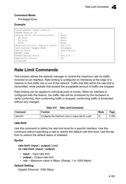
Rate Limit Commands 4
Command ModePrivileged Exec
Example
Rate Limit CommandsThis function allows the network manager to control the maximum rate for traffic received on an interface. Rate limiting is configured on interfaces at the edge of a network to limit traffic into or out of the network. Traffic that falls within the rate limit is transmitted, while packets that exceed the acceptable amount of traffic are dropped.
Rate limiting can be applied to individual ports or trunks. When an interface is configured with this feature, the traffic rate will be monitored by the hardware to verify conformity. Non-conforming traffic is dropped, conforming traffic is forwarded without any changes.
rate-limit
Use this command to define the rate limit level for a specific interface. Use this command without specifying a rate to restore the default rate limit level. Use the no form to restore the default status of disabled.
Syntax
rate-limit {input | output} [rate]no rate-limit {input | output}
• input – Input rate limit• output – Output rate limit• rate – Maximum value in Mbps. (Range: 1 to 1000 Mbps)
Default Setting
Gigabit Ethernet: 1000 Mbps
Console#show rspan sessionRSPAN Session ID : 1Source Ports (mirrored ports) : None RX Only : None TX Only : None BOTH : NoneDestination Port (monitor port) : Eth 1/2Destination Tagged Mode : UntaggedSwitch Role : DestinationRSPAN VLAN : 2RSPAN Uplink Ports : Eth 1/3Operation Status : UpConsole#
Table 4-57 Rate Limit Commands
Command Function Mode Page
rate-limit Configures the maximum input or output rate for a port IC 4-185
4-185
Command Line Interface4
Command ModeInterface Configuration (Ethernet, Port Channel)
Example
Address Table CommandsThese commands are used to configure the address table for filtering specified addresses, displaying current entries, clearing the table, or setting the aging time.
mac-address-table staticThis command maps a static address to a destination port in a VLAN. Use the no form to remove an address.
Syntax
mac-address-table static mac-address interface interface vlan vlan-id [action]
no mac-address-table static mac-address vlan vlan-id
• mac-address - MAC address. • interface
• ethernet unit/port- unit - Stack unit. (Range: 1) - port - Port number. (Range: 1-26/50)
• port-channel channel-id (Range: 1-32) • vlan-id - VLAN ID (Range: 1-4094) • action -
- delete-on-reset - Assignment lasts until the switch is reset. - permanent - Assignment is permanent.
Console(config)#interface ethernet 1/1Console(config-if)#rate-limit input 1000Console(config-if)#
Table 4-58 Address Table Commands
Command Function Mode Page
mac-address-table static Maps a static address to a port in a VLAN GC 4-186
clear mac-address-table dynamic
Removes any learned entries from the forwarding database PE 4-187
show mac-address-table Displays entries in the bridge-forwarding database PE 4-188
mac-address-table aging-time
Sets the aging time of the address table GC 4-189
show mac-address-table aging-time
Shows the aging time for the address table PE 4-189
4-186
Address Table Commands 4
Default SettingNo static addresses are defined. The default mode is permanent.
Command Mode
Global Configuration
Command Usage
The static address for a host device can be assigned to a specific port within a specific VLAN. Use this command to add static addresses to the MAC Address Table. Static addresses have the following characteristics:
• Static addresses will not be removed from the address table when a given interface link is down.
• Static addresses are bound to the assigned interface and will not be moved. When a static address is seen on another interface, the address will be ignored and will not be written to the address table.
• A static address cannot be learned on another port until the address is removed with the no form of this command.
Example
clear mac-address-table dynamicThis command removes any learned entries from the forwarding database and clears the transmit and receive counts for any static or system configured entries.
Default Setting
None
Command Mode
Privileged Exec
Example
Console(config)#mac-address-table static 00-13-F7-A8-AF-52 interface ethernet 1/1 vlan 1 delete-on-reset
Console(config)#
Console#clear mac-address-table dynamicConsole#
4-187
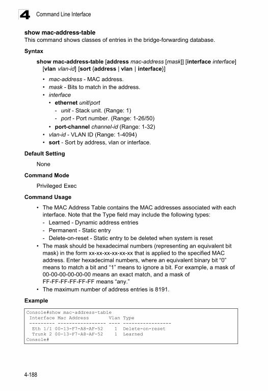
Command Line Interface4
show mac-address-tableThis command shows classes of entries in the bridge-forwarding database.Syntax
show mac-address-table [address mac-address [mask]] [interface interface] [vlan vlan-id] [sort {address | vlan | interface}]
• mac-address - MAC address.• mask - Bits to match in the address. • interface
• ethernet unit/port- unit - Stack unit. (Range: 1)- port - Port number. (Range: 1-26/50)
• port-channel channel-id (Range: 1-32) • vlan-id - VLAN ID (Range: 1-4094) • sort - Sort by address, vlan or interface.
Default Setting
None
Command Mode
Privileged Exec
Command Usage
• The MAC Address Table contains the MAC addresses associated with each interface. Note that the Type field may include the following types:- Learned - Dynamic address entries- Permanent - Static entry- Delete-on-reset - Static entry to be deleted when system is reset
• The mask should be hexadecimal numbers (representing an equivalent bit mask) in the form xx-xx-xx-xx-xx-xx that is applied to the specified MAC address. Enter hexadecimal numbers, where an equivalent binary bit “0” means to match a bit and “1” means to ignore a bit. For example, a mask of 00-00-00-00-00-00 means an exact match, and a mask of FF-FF-FF-FF-FF-FF means “any.”
• The maximum number of address entries is 8191.
Example
Console#show mac-address-table Interface Mac Address Vlan Type --------- ----------------- ---- ----------------- Eth 1/1 00-13-F7-A8-AF-52 1 Delete-on-reset Trunk 2 00-13-F7-A8-AF-52 1 LearnedConsole#
4-188
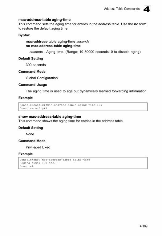
Address Table Commands 4
mac-address-table aging-timeThis command sets the aging time for entries in the address table. Use the no form to restore the default aging time.Syntax
mac-address-table aging-time secondsno mac-address-table aging-time
seconds - Aging time. (Range: 10-30000 seconds; 0 to disable aging)
Default Setting
300 seconds
Command Mode
Global Configuration
Command Usage
The aging time is used to age out dynamically learned forwarding information.
Example
show mac-address-table aging-timeThis command shows the aging time for entries in the address table.
Default Setting
None
Command Mode
Privileged Exec
Example
Console(config)#mac-address-table aging-time 100Console(config)#
Console#show mac-address-table aging-time Aging time: 100 sec.Console#
4-189
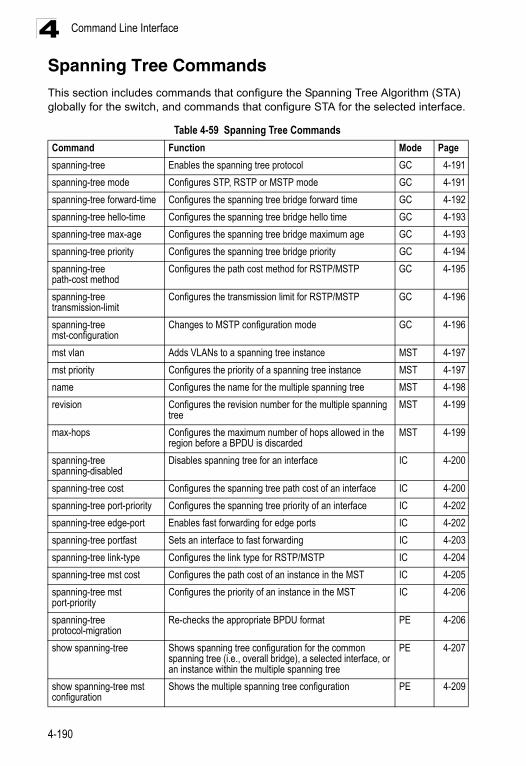
Command Line Interface4
Spanning Tree CommandsThis section includes commands that configure the Spanning Tree Algorithm (STA) globally for the switch, and commands that configure STA for the selected interface.Table 4-59 Spanning Tree Commands
Command Function Mode Page
spanning-tree Enables the spanning tree protocol GC 4-191
spanning-tree mode Configures STP, RSTP or MSTP mode GC 4-191
spanning-tree forward-time Configures the spanning tree bridge forward time GC 4-192
spanning-tree hello-time Configures the spanning tree bridge hello time GC 4-193
spanning-tree max-age Configures the spanning tree bridge maximum age GC 4-193
spanning-tree priority Configures the spanning tree bridge priority GC 4-194
spanning-tree path-cost method
Configures the path cost method for RSTP/MSTP GC 4-195
spanning-tree transmission-limit
Configures the transmission limit for RSTP/MSTP GC 4-196
spanning-tree mst-configuration
Changes to MSTP configuration mode GC 4-196
mst vlan Adds VLANs to a spanning tree instance MST 4-197
mst priority Configures the priority of a spanning tree instance MST 4-197
name Configures the name for the multiple spanning tree MST 4-198
revision Configures the revision number for the multiple spanning tree
MST 4-199
max-hops Configures the maximum number of hops allowed in the region before a BPDU is discarded
MST 4-199
spanning-tree spanning-disabled
Disables spanning tree for an interface IC 4-200
spanning-tree cost Configures the spanning tree path cost of an interface IC 4-200
spanning-tree port-priority Configures the spanning tree priority of an interface IC 4-202
spanning-tree edge-port Enables fast forwarding for edge ports IC 4-202
spanning-tree portfast Sets an interface to fast forwarding IC 4-203
spanning-tree link-type Configures the link type for RSTP/MSTP IC 4-204
spanning-tree mst cost Configures the path cost of an instance in the MST IC 4-205
spanning-tree mst port-priority
Configures the priority of an instance in the MST IC 4-206
spanning-tree protocol-migration
Re-checks the appropriate BPDU format PE 4-206
show spanning-tree Shows spanning tree configuration for the common spanning tree (i.e., overall bridge), a selected interface, or an instance within the multiple spanning tree
PE 4-207
show spanning-tree mst configuration
Shows the multiple spanning tree configuration PE 4-209
4-190
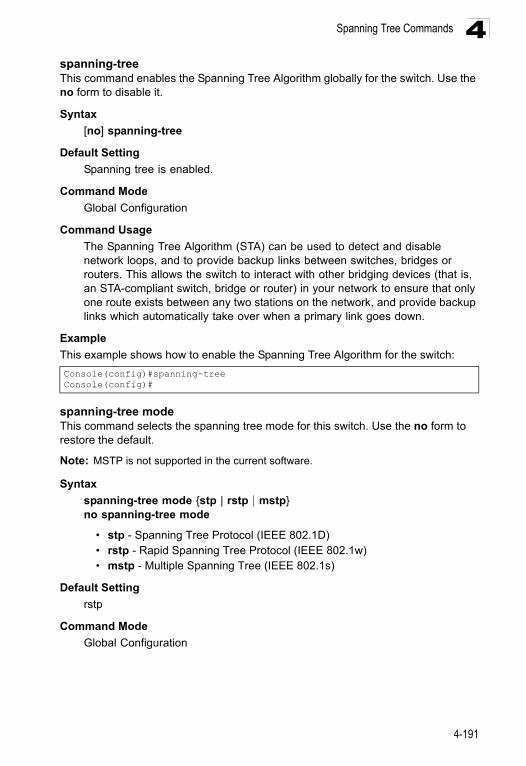
Spanning Tree Commands 4
spanning-treeThis command enables the Spanning Tree Algorithm globally for the switch. Use the no form to disable it.Syntax
[no] spanning-tree
Default Setting
Spanning tree is enabled.
Command Mode
Global Configuration
Command Usage
The Spanning Tree Algorithm (STA) can be used to detect and disable network loops, and to provide backup links between switches, bridges or routers. This allows the switch to interact with other bridging devices (that is, an STA-compliant switch, bridge or router) in your network to ensure that only one route exists between any two stations on the network, and provide backup links which automatically take over when a primary link goes down.
Example
This example shows how to enable the Spanning Tree Algorithm for the switch:
spanning-tree modeThis command selects the spanning tree mode for this switch. Use the no form to restore the default.
Note: MSTP is not supported in the current software.
Syntax
spanning-tree mode {stp | rstp | mstp}no spanning-tree mode
• stp - Spanning Tree Protocol (IEEE 802.1D)• rstp - Rapid Spanning Tree Protocol (IEEE 802.1w)• mstp - Multiple Spanning Tree (IEEE 802.1s)
Default Setting
rstp
Command Mode
Global Configuration
Console(config)#spanning-treeConsole(config)#
4-191
Command Line Interface4
Command Usage• Spanning Tree Protocol
Uses RSTP for the internal state machine, but sends only 802.1D BPDUs.
- This creates one spanning tree instance for the entire network. If multiple VLANs are implemented on a network, the path between specific VLAN members may be inadvertently disabled to prevent network loops, thus isolating group members. When operating multiple VLANs, we recommend selecting the MSTP option.
• Rapid Spanning Tree Protocol
RSTP supports connections to either STP or RSTP nodes by monitoring the incoming protocol messages and dynamically adjusting the type of protocol messages the RSTP node transmits, as described below:
- STP Mode – If the switch receives an 802.1D BPDU after a port’s migration delay timer expires, the switch assumes it is connected to an 802.1D bridge and starts using only 802.1D BPDUs.
- RSTP Mode – If RSTP is using 802.1D BPDUs on a port and receives an RSTP BPDU after the migration delay expires, RSTP restarts the migration delay timer and begins using RSTP BPDUs on that port.
• Multiple Spanning Tree Protocol
- To allow multiple spanning trees to operate over the network, you must configure a related set of bridges with the same MSTP configuration, allowing them to participate in a specific set of spanning tree instances.
- A spanning tree instance can exist only on bridges that have compatible VLAN instance assignments.
- Be careful when switching between spanning tree modes. Changing modes stops all spanning-tree instances for the previous mode and restarts the system in the new mode, temporarily disrupting user traffic.
Example
The following example configures the switch to use Rapid Spanning Tree:
spanning-tree forward-timeThis command configures the spanning tree bridge forward time globally for this switch. Use the no form to restore the default.
Syntax
spanning-tree forward-time secondsno spanning-tree forward-time
seconds - Time in seconds. (Range: 4 - 30 seconds)The minimum value is the higher of 4 or [(max-age / 2) + 1].
Console(config)#spanning-tree mode rstpConsole(config)#
4-192
Spanning Tree Commands 4
Default Setting15 seconds
Command Mode
Global Configuration
Command Usage
This command sets the maximum time (in seconds) the root device will wait before changing states (i.e., discarding to learning to forwarding). This delay is required because every device must receive information about topology changes before it starts to forward frames. In addition, each port needs time to listen for conflicting information that would make it return to the discarding state; otherwise, temporary data loops might result.
Example
spanning-tree hello-timeThis command configures the spanning tree bridge hello time globally for this switch. Use the no form to restore the default.
Syntax
spanning-tree hello-time timeno spanning-tree hello-time
time - Time in seconds. (Range: 1-10 seconds). The maximum value is the lower of 10 or [(max-age / 2) -1].
Default Setting
2 seconds
Command Mode
Global Configuration
Command Usage
This command sets the time interval (in seconds) at which the root device transmits a configuration message.
Example
Related Commands
spanning-tree forward-time (4-192)spanning-tree max-age (4-193)
Console(config)#spanning-tree forward-time 20Console(config)#
Console(config)#spanning-tree hello-time 5Console(config)#
4-193
Command Line Interface4
spanning-tree max-ageThis command configures the spanning tree bridge maximum age globally for this switch. Use the no form to restore the default.Syntax
spanning-tree max-age secondsno spanning-tree max-age
seconds - Time in seconds. (Range: 6-40 seconds)The minimum value is the higher of 6 or [2 x (hello-time + 1)].The maximum value is the lower of 40 or [2 x (forward-time - 1)].
Default Setting
20 seconds
Command Mode
Global Configuration
Command Usage
This command sets the maximum time (in seconds) a device can wait without receiving a configuration message before attempting to reconfigure. All device ports (except for designated ports) should receive configuration messages at regular intervals. Any port that ages out STA information (provided in the last configuration message) becomes the designated port for the attached LAN. If it is a root port, a new root port is selected from among the device ports attached to the network.
Example
Related Commands
spanning-tree forward-time (4-192)spanning-tree hello-time (4-193)
spanning-tree priorityThis command configures the spanning tree priority globally for this switch. Use the no form to restore the default.
Syntax
spanning-tree priority priority no spanning-tree priority
priority - Priority of the bridge. (Range: 0 - 65535) (Range – 0-61440, in steps of 4096; Options: 0, 4096, 8192, 12288, 16384, 20480, 24576, 28672, 32768, 36864, 40960, 45056, 49152, 53248, 57344, 61440)
Console(config)#spanning-tree max-age 40Console(config)#
4-194
Spanning Tree Commands 4
Default Setting32768
Command Mode
Global Configuration
Command Usage
Bridge priority is used in selecting the root device, root port, and designated port. The device with the highest priority (i.e., lower numeric value) becomes the STA root device. However, if all devices have the same priority, the device with the lowest MAC address will then become the root device.
Example
spanning-tree pathcost methodThis command configures the path cost method used for Rapid Spanning Tree and Multiple Spanning Tree. Use the no form to restore the default.
Syntax
spanning-tree pathcost method {long | short} no spanning-tree pathcost method
• long - Specifies 32-bit based values that range from 1-200,000,000. This method is based on the IEEE 802.1w Rapid Spanning Tree Protocol.
• short - Specifies 16-bit based values that range from 1-65535. This method is based on the IEEE 802.1 Spanning Tree Protocol.
Default Setting
Long method
Command Mode
Global Configuration
Command Usage
The path cost method is used to determine the best path between devices. Therefore, lower values should be assigned to ports attached to faster media, and higher values assigned to ports with slower media. Note that path cost (page 4-200) takes precedence over port priority (page 4-202).
Example
Console(config)#spanning-tree priority 40000Console(config)#
Console(config)#spanning-tree pathcost method longConsole(config)#
4-195
Command Line Interface4
spanning-tree transmission-limitThis command configures the minimum interval between the transmission of consecutive RSTP/MSTP BPDUs. Use the no form to restore the default.Syntax
spanning-tree transmission-limit countno spanning-tree transmission-limit
count - The transmission limit in seconds. (Range: 1-10)
Default Setting
3
Command Mode
Global Configuration
Command Usage
This command limits the maximum transmission rate for BPDUs.
Example
spanning-tree mst-configuration This command changes to Multiple Spanning Tree (MST) configuration mode.
Default Setting
• No VLANs are mapped to any MST instance.• The region name is set the switch’s MAC address.
Command Mode
Global Configuration
Example
Related Commands
mst vlan (4-197)mst priority (4-197)name (4-198)revision (4-199)max-hops (4-199)
Console(config)#spanning-tree transmission-limit 4Console(config)#
Console(config)#spanning-tree mst-configurationConsole(config-mstp)#
4-196
Spanning Tree Commands 4
mst vlanThis command adds VLANs to a spanning tree instance. Use the no form to remove the specified VLANs. Using the no form without any VLAN parameters to remove all VLANs.Syntax
[no] mst instance_id vlan vlan-range
• instance_id - Instance identifier of the spanning tree. (Range: 0-4094)• vlan-range - Range of VLANs. (Range: 1-4094)
Default Setting
none
Command Mode
MST Configuration
Command Usage
• Use this command to group VLANs into spanning tree instances. MSTP generates a unique spanning tree for each instance. This provides multiple pathways across the network, thereby balancing the traffic load, preventing wide-scale disruption when a bridge node in a single instance fails, and allowing for faster convergence of a new topology for the failed instance.
• By default all VLANs are assigned to the Internal Spanning Tree (MSTI 0) that connects all bridges and LANs within the MST region. This switch supports up to 58 instances. You should try to group VLANs which cover the same general area of your network. However, remember that you must configure all bridges within the same MSTI Region (page 4-198) with the same set of instances, and the same instance (on each bridge) with the same set of VLANs. Also, note that RSTP treats each MSTI region as a single node, connecting all regions to the Common Spanning Tree.
Example
mst priorityThis command configures the priority of a spanning tree instance. Use the no form to restore the default.
Syntax
mst instance_id priority priorityno mst instance_id priority
• instance_id - Instance identifier of the spanning tree. (Range: 0-4094)• priority - Priority of the a spanning tree instance.
(Range: 0-61440 in steps of 4096; Options: 0, 4096, 8192, 12288, 16384, 20480, 24576, 28672, 32768, 36864, 40960, 45056, 49152, 53248, 57344, 61440)
Console(config-mstp)#mst 1 vlan 2-5Console(config-mstp)#
4-197
Command Line Interface4
Default Setting32768
Command Mode
MST Configuration
Command Usage
• MST priority is used in selecting the root bridge and alternate bridge of the specified instance. The device with the highest priority (i.e., lowest numerical value) becomes the MSTI root device. However, if all devices have the same priority, the device with the lowest MAC address will then become the root device.
• You can set this switch to act as the MSTI root device by specifying a priority of 0, or as the MSTI alternate device by specifying a priority of 16384.
Example
nameThis command configures the name for the multiple spanning tree region in which this switch is located. Use the no form to clear the name.
Syntax
name name
name - Name of the spanning tree.
Default Setting
Switch’s MAC address
Command Mode
MST Configuration
Command Usage
The MST region name and revision number (page 4-199) are used to designate a unique MST region. A bridge (i.e., spanning-tree compliant device such as this switch) can only belong to one MST region. And all bridges in the same region must be configured with the same MST instances.
Example
Related Commands
revision (4-199)
Console(config-mstp)#mst 1 priority 4096Console(config-mstp)#
Console(config-mstp)#name R&DConsole(config-mstp)#
4-198
Spanning Tree Commands 4
revisionThis command configures the revision number for this multiple spanning tree configuration of this switch. Use the no form to restore the default.Syntax
revision number
number - Revision number of the spanning tree. (Range: 0-65535)
Default Setting
0
Command Mode
MST Configuration
Command Usage
The MST region name (page 4-198) and revision number are used to designate a unique MST region. A bridge (i.e., spanning-tree compliant device such as this switch) can only belong to one MST region. And all bridges in the same region must be configured with the same MST instances.
Example
Related Commands
name (4-198)
max-hopsThis command configures the maximum number of hops in the region before a BPDU is discarded. Use the no form to restore the default.
Syntax
max-hops hop-number
hop-number - Maximum hop number for multiple spanning tree. (Range: 1-40)
Default Setting
20
Command Mode
MST Configuration
Command Usage
An MSTI region is treated as a single node by the STP and RSTP protocols. Therefore, the message age for BPDUs inside an MSTI region is never changed. However, each spanning tree instance within a region, and the internal spanning tree (IST) that connects these instances use a hop count to specify the maximum number of bridges that will propagate a BPDU. Each
Console(config-mstp)#revision 1Console(config-mstp)#
4-199
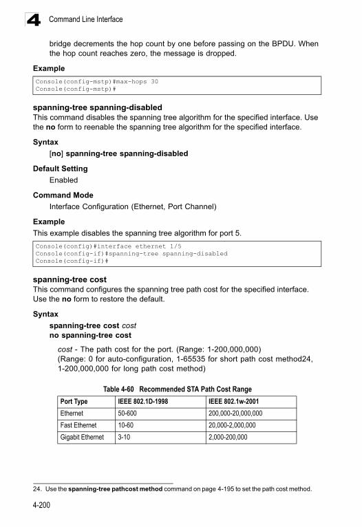
Command Line Interface4
bridge decrements the hop count by one before passing on the BPDU. When the hop count reaches zero, the message is dropped.Example
spanning-tree spanning-disabledThis command disables the spanning tree algorithm for the specified interface. Use the no form to reenable the spanning tree algorithm for the specified interface.
Syntax
[no] spanning-tree spanning-disabled
Default Setting
Enabled
Command Mode
Interface Configuration (Ethernet, Port Channel)
Example
This example disables the spanning tree algorithm for port 5.
spanning-tree costThis command configures the spanning tree path cost for the specified interface. Use the no form to restore the default.
Syntax
spanning-tree cost costno spanning-tree cost
cost - The path cost for the port. (Range: 1-200,000,000)(Range: 0 for auto-configuration, 1-65535 for short path cost method24, 1-200,000,000 for long path cost method)
Console(config-mstp)#max-hops 30Console(config-mstp)#
Console(config)#interface ethernet 1/5Console(config-if)#spanning-tree spanning-disabledConsole(config-if)#
24. Use the spanning-tree pathcost method command on page 4-195 to set the path cost method.
Table 4-60 Recommended STA Path Cost Range
Port Type IEEE 802.1D-1998 IEEE 802.1w-2001
Ethernet 50-600 200,000-20,000,000
Fast Ethernet 10-60 20,000-2,000,000
Gigabit Ethernet 3-10 2,000-200,000
4-200
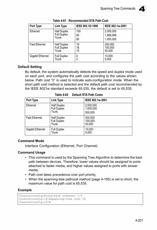
Spanning Tree Commands 4
Default Setting
By default, the system automatically detects the speed and duplex mode used on each port, and configures the path cost according to the values shown below. Path cost “0” is used to indicate auto-configuration mode. When the short path cost method is selected and the default path cost recommended by the IEEE 8021w standard exceeds 65,535, the default is set to 65,535.
Command Mode
Interface Configuration (Ethernet, Port Channel)
Command Usage
• This command is used by the Spanning Tree Algorithm to determine the best path between devices. Therefore, lower values should be assigned to ports attached to faster media, and higher values assigned to ports with slower media.
• Path cost takes precedence over port priority.• When the spanning-tree pathcost method (page 4-195) is set to short, the
maximum value for path cost is 65,535.
Example
Table 4-61 Recommended STA Path Cost
Port Type Link Type IEEE 802.1D-1998 IEEE 802.1w-2001
Ethernet Half DuplexFull DuplexTrunk
1009590
2,000,0001,999,9991,000,000
Fast Ethernet Half DuplexFull DuplexTrunk
191815
200,000100,00050,000
Gigabit Ethernet Full DuplexTrunk
43
10,0005,000
Table 4-62 Default STA Path Costs
Port Type Link Type IEEE 802.1w-2001
Ethernet Half DuplexFull DuplexTrunk
2,000,0001,000,000500,000
Fast Ethernet Half DuplexFull DuplexTrunk
200,000100,00050,000
Gigabit Ethernet Full DuplexTrunk
10,0005,000
Console(config)#interface ethernet 1/5Console(config-if)#spanning-tree cost 50Console(config-if)#
4-201
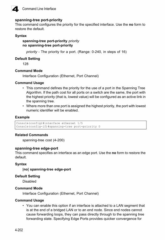
Command Line Interface4
spanning-tree port-priorityThis command configures the priority for the specified interface. Use the no form to restore the default.Syntax
spanning-tree port-priority priorityno spanning-tree port-priority
priority - The priority for a port. (Range: 0-240, in steps of 16)
Default Setting
128
Command Mode
Interface Configuration (Ethernet, Port Channel)
Command Usage
• This command defines the priority for the use of a port in the Spanning Tree Algorithm. If the path cost for all ports on a switch are the same, the port with the highest priority (that is, lowest value) will be configured as an active link in the spanning tree.
• Where more than one port is assigned the highest priority, the port with lowest numeric identifier will be enabled.
Example
Related Commands
spanning-tree cost (4-200)
spanning-tree edge-portThis command specifies an interface as an edge port. Use the no form to restore the default.
Syntax
[no] spanning-tree edge-port
Default Setting
Disabled
Command Mode
Interface Configuration (Ethernet, Port Channel)
Command Usage
• You can enable this option if an interface is attached to a LAN segment that is at the end of a bridged LAN or to an end node. Since end nodes cannot cause forwarding loops, they can pass directly through to the spanning tree forwarding state. Specifying Edge Ports provides quicker convergence for
Console(config)#interface ethernet 1/5Console(config-if)#spanning-tree port-priority 0
4-202
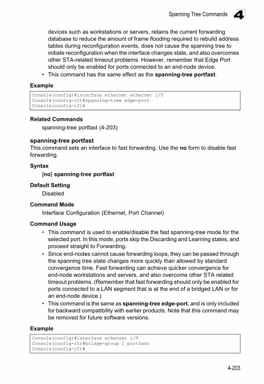
Spanning Tree Commands 4
devices such as workstations or servers, retains the current forwarding database to reduce the amount of frame flooding required to rebuild address tables during reconfiguration events, does not cause the spanning tree to initiate reconfiguration when the interface changes state, and also overcomes other STA-related timeout problems. However, remember that Edge Port should only be enabled for ports connected to an end-node device.• This command has the same effect as the spanning-tree portfast.
Example
Related Commands
spanning-tree portfast (4-203)
spanning-tree portfastThis command sets an interface to fast forwarding. Use the no form to disable fast forwarding.
Syntax
[no] spanning-tree portfast
Default Setting
Disabled
Command Mode
Interface Configuration (Ethernet, Port Channel)
Command Usage
• This command is used to enable/disable the fast spanning-tree mode for the selected port. In this mode, ports skip the Discarding and Learning states, and proceed straight to Forwarding.
• Since end-nodes cannot cause forwarding loops, they can be passed through the spanning tree state changes more quickly than allowed by standard convergence time. Fast forwarding can achieve quicker convergence for end-node workstations and servers, and also overcome other STA related timeout problems. (Remember that fast forwarding should only be enabled for ports connected to a LAN segment that is at the end of a bridged LAN or for an end-node device.)
• This command is the same as spanning-tree edge-port, and is only included for backward compatibility with earlier products. Note that this command may be removed for future software versions.
Example
Console(config)#interface ethernet ethernet 1/5Console(config-if)#spanning-tree edge-portConsole(config-if)#
Console(config)#interface ethernet 1/5Console(config-if)#bridge-group 1 portfastConsole(config-if)#
4-203
Command Line Interface4
Related Commandsspanning-tree edge-port (4-202)
spanning-tree link-typeThis command configures the link type for Rapid Spanning Tree and Multiple Spanning Tree. Use the no form to restore the default.
Syntax
spanning-tree link-type {auto | point-to-point | shared}no spanning-tree link-type
• auto - Automatically derived from the duplex mode setting. • point-to-point - Point-to-point link.• shared - Shared medium.
Default Setting
auto
Command Mode
Interface Configuration (Ethernet, Port Channel)
Command Usage
• Specify a point-to-point link if the interface can only be connected to exactly one other bridge, or a shared link if it can be connected to two or more bridges.
• When automatic detection is selected, the switch derives the link type from the duplex mode. A full-duplex interface is considered a point-to-point link, while a half-duplex interface is assumed to be on a shared link.
• RSTP only works on point-to-point links between two bridges. If you designate a port as a shared link, RSTP is forbidden. Since MSTP is an extension of RSTP, this same restriction applies.
Example
Console(config)#interface ethernet ethernet 1/5Console(config-if)#spanning-tree link-type point-to-pointConsole(config-if)#
4-204
Spanning Tree Commands 4
spanning-tree mst costThis command configures the path cost on a spanning instance in the Multiple Spanning Tree. Use the no form to restore the default.Syntax
spanning-tree mst instance_id cost costno spanning-tree mst instance_id cost
• instance_id - Instance identifier of the spanning tree. (Range: 0-4094, no leading zeroes)
• cost - Path cost for an interface. (Range: 0 for auto-configuration, 1-65535 for short path cost method25, 1-200,000,000 for long path cost method)
The recommended path cost range is listed in Table 4-60 on page 4-200. The recommended path cost is listed in Table 4-61 on page 4-201.
Default Setting
By default, the system automatically detects the speed and duplex mode used on each port, and configures the path cost according to the values shown below. Path cost “0” is used to indicate auto-configuration mode.
• Ethernet – half duplex: 2,000,000; full duplex: 1,000,000; trunk: 500,000• Fast Ethernet – half duplex: 200,000; full duplex: 100,000; trunk: 50,000• Gigabit Ethernet – full duplex: 10,000; trunk: 5,000• 10 Gigabit Ethernet – full duplex: 1000; trunk: 500
Command Mode
Interface Configuration (Ethernet, Port Channel)
Command Usage
• Each spanning-tree instance is associated with a unique set of VLAN IDs. • This command is used by the multiple spanning-tree algorithm to determine
the best path between devices. Therefore, lower values should be assigned to interfaces attached to faster media, and higher values assigned to interfaces with slower media.
• Use the no spanning-tree mst cost command to specify auto-configuration mode.
• Path cost takes precedence over interface priority.
Example
Related Commands
spanning-tree mst port-priority (4-206)
25. Use the spanning-tree pathcost method command on page 4-195 to set the path cost method.
Console(config)#interface ethernet ethernet 1/5Console(config-if)#spanning-tree mst 1 cost 50Console(config-if)#
4-205
Command Line Interface4
spanning-tree mst port-priorityThis command configures the interface priority on a spanning instance in the Multiple Spanning Tree. Use the no form to restore the default.Syntax
spanning-tree mst instance_id port-priority priorityno spanning-tree mst instance_id port-priority
• instance_id - Instance identifier of the spanning tree. (Range: 0-4094, no leading zeroes)
• priority - Priority for an interface. (Range: 0-240 in steps of 16)
Default Setting
128
Command Mode
Interface Configuration (Ethernet, Port Channel)
Command Usage
• This command defines the priority for the use of an interface in the multiple spanning-tree. If the path cost for all interfaces on a switch are the same, the interface with the highest priority (that is, lowest value) will be configured as an active link in the spanning tree.
• Where more than one interface is assigned the highest priority, the interface with lowest numeric identifier will be enabled.
Example
Related Commands
spanning-tree mst cost (4-205)
spanning-tree protocol-migrationThis command re-checks the appropriate BPDU format to send on the selected interface.
Syntax
spanning-tree protocol-migration interface
interface
• ethernet unit/port- unit - Stack unit. (Range: 1) - port - Port number. (Range: 1-26/50)
• port-channel channel-id (Range: 1-32)
Command Mode
Privileged Exec
Console(config)#interface ethernet ethernet 1/5Console(config-if)#spanning-tree mst 1 port-priority 0Console(config-if)#
4-206
Spanning Tree Commands 4
Command UsageIf at any time the switch detects STP BPDUs, including Configuration or Topology Change Notification BPDUs, it will automatically set the selected interface to forced STP-compatible mode. However, you can also use the spanning-tree protocol-migration command at any time to manually re-check the appropriate BPDU format to send on the selected interfaces (i.e., RSTP or STP-compatible).
Example
show spanning-treeThis command shows the configuration for the common spanning tree (CST) or for an instance within the multiple spanning tree (MST).
Syntax
show spanning-tree [interface | mst instance-id]
• interface • ethernet unit/port
- unit - Stack unit. (Range: 1) - port - Port number. (Range: 1-26/50)
• port-channel channel-id (Range: 1-32)
• instance-id - Instance identifier of the multiple spanning tree. (Range: 0-4094, no leading zeroes)
Default Setting
None
Command Mode
Privileged Exec
Command Usage
• Use the show spanning-tree command with no parameters to display the spanning tree configuration for the switch for the Common Spanning Tree (CST) and for every interface in the tree.
• Use the show spanning-tree interface command to display the spanning tree configuration for an interface within the Common Spanning Tree (CST).
• Use the show spanning-tree mst instance_id command to display the spanning tree configuration for an instance within the Multiple Spanning Tree (MST).
• For a description of the items displayed under “Spanning-tree information,” see "Configuring Global Settings for STA" on page 3-127. For a description of the items displayed for specific interfaces, see "Displaying Interface Settings for STA" on page 3-131.
Console#spanning-tree protocol-migration eth 1/5Console#
4-207
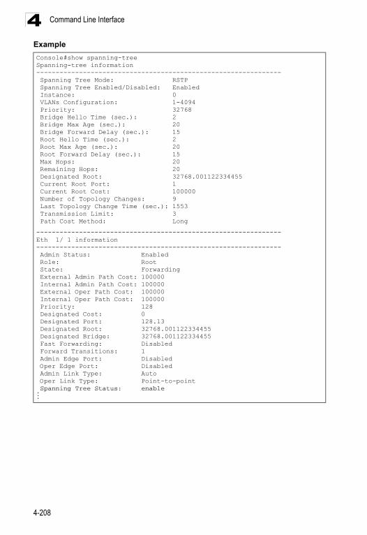
Command Line Interface4
ExampleConsole#show spanning-treeSpanning-tree information--------------------------------------------------------------- Spanning Tree Mode: RSTP Spanning Tree Enabled/Disabled: Enabled Instance: 0 VLANs Configuration: 1-4094 Priority: 32768 Bridge Hello Time (sec.): 2 Bridge Max Age (sec.): 20 Bridge Forward Delay (sec.): 15 Root Hello Time (sec.): 2 Root Max Age (sec.): 20 Root Forward Delay (sec.): 15 Max Hops: 20 Remaining Hops: 20 Designated Root: 32768.001122334455 Current Root Port: 1 Current Root Cost: 100000 Number of Topology Changes: 9 Last Topology Change Time (sec.): 1553 Transmission Limit: 3 Path Cost Method: Long
---------------------------------------------------------------Eth 1/ 1 information--------------------------------------------------------------- Admin Status: Enabled Role: Root State: Forwarding External Admin Path Cost: 100000 Internal Admin Path Cost: 100000 External Oper Path Cost: 100000 Internal Oper Path Cost: 100000 Priority: 128 Designated Cost: 0 Designated Port: 128.13 Designated Root: 32768.001122334455 Designated Bridge: 32768.001122334455 Fast Forwarding: Disabled Forward Transitions: 1 Admin Edge Port: Disabled Oper Edge Port: Disabled Admin Link Type: Auto Oper Link Type: Point-to-point Spanning Tree Status: enable...
4-208
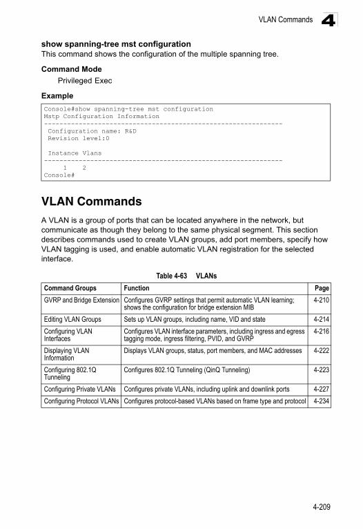
VLAN Commands 4
show spanning-tree mst configurationThis command shows the configuration of the multiple spanning tree.Command Mode
Privileged Exec
Example
VLAN CommandsA VLAN is a group of ports that can be located anywhere in the network, but communicate as though they belong to the same physical segment. This section describes commands used to create VLAN groups, add port members, specify how VLAN tagging is used, and enable automatic VLAN registration for the selected interface.
Console#show spanning-tree mst configurationMstp Configuration Information-------------------------------------------------------------- Configuration name: R&D Revision level:0
Instance Vlans-------------------------------------------------------------- 1 2Console#
Table 4-63 VLANs
Command Groups Function Page
GVRP and Bridge Extension Configures GVRP settings that permit automatic VLAN learning; shows the configuration for bridge extension MIB
4-210
Editing VLAN Groups Sets up VLAN groups, including name, VID and state 4-214
Configuring VLAN Interfaces
Configures VLAN interface parameters, including ingress and egress tagging mode, ingress filtering, PVID, and GVRP
4-216
Displaying VLAN Information
Displays VLAN groups, status, port members, and MAC addresses 4-222
Configuring 802.1Q Tunneling
Configures 802.1Q Tunneling (QinQ Tunneling) 4-223
Configuring Private VLANs Configures private VLANs, including uplink and downlink ports 4-227
Configuring Protocol VLANs Configures protocol-based VLANs based on frame type and protocol 4-234
4-209
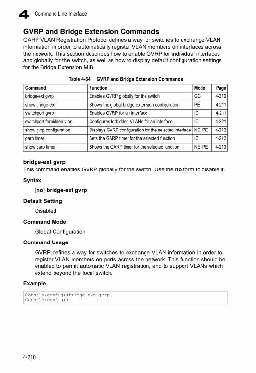
Command Line Interface4
GVRP and Bridge Extension CommandsGARP VLAN Registration Protocol defines a way for switches to exchange VLAN information in order to automatically register VLAN members on interfaces across the network. This section describes how to enable GVRP for individual interfaces and globally for the switch, as well as how to display default configuration settings for the Bridge Extension MIB.bridge-ext gvrpThis command enables GVRP globally for the switch. Use the no form to disable it.
Syntax
[no] bridge-ext gvrp
Default Setting
Disabled
Command Mode
Global Configuration
Command Usage
GVRP defines a way for switches to exchange VLAN information in order to register VLAN members on ports across the network. This function should be enabled to permit automatic VLAN registration, and to support VLANs which extend beyond the local switch.
Example
Table 4-64 GVRP and Bridge Extension Commands
Command Function Mode Page
bridge-ext gvrp Enables GVRP globally for the switch GC 4-210
show bridge-ext Shows the global bridge extension configuration PE 4-211
switchport gvrp Enables GVRP for an interface IC 4-211
switchport forbidden vlan Configures forbidden VLANs for an interface IC 4-221
show gvrp configuration Displays GVRP configuration for the selected interface NE, PE 4-212
garp timer Sets the GARP timer for the selected function IC 4-212
show garp timer Shows the GARP timer for the selected function NE, PE 4-213
Console(config)#bridge-ext gvrpConsole(config)#
4-210
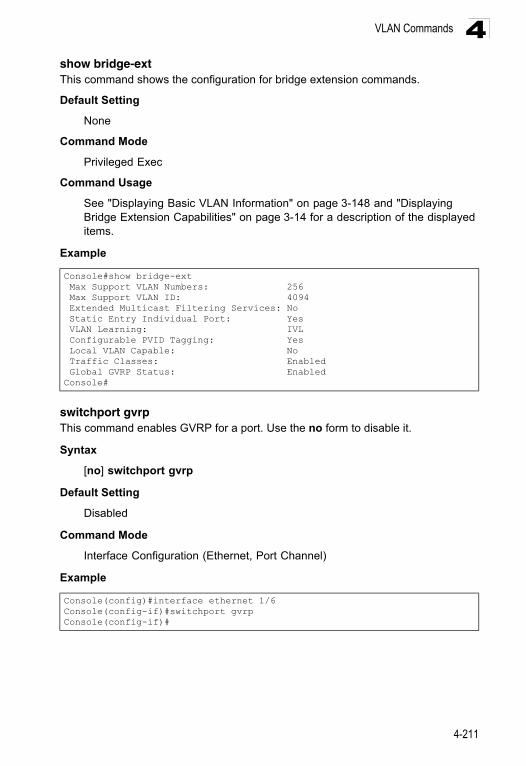
VLAN Commands 4
show bridge-extThis command shows the configuration for bridge extension commands.Default Setting
None
Command Mode
Privileged Exec
Command Usage
See "Displaying Basic VLAN Information" on page 3-148 and "Displaying Bridge Extension Capabilities" on page 3-14 for a description of the displayed items.
Example
switchport gvrpThis command enables GVRP for a port. Use the no form to disable it.
Syntax
[no] switchport gvrp
Default Setting
Disabled
Command Mode
Interface Configuration (Ethernet, Port Channel)
Example
Console#show bridge-ext Max Support VLAN Numbers: 256 Max Support VLAN ID: 4094 Extended Multicast Filtering Services: No Static Entry Individual Port: Yes VLAN Learning: IVL Configurable PVID Tagging: Yes Local VLAN Capable: No Traffic Classes: Enabled Global GVRP Status: EnabledConsole#
Console(config)#interface ethernet 1/6Console(config-if)#switchport gvrpConsole(config-if)#
4-211
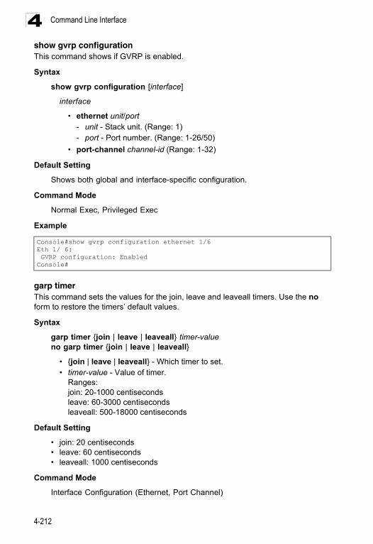
Command Line Interface4
show gvrp configurationThis command shows if GVRP is enabled.Syntax
show gvrp configuration [interface]
interface
• ethernet unit/port - unit - Stack unit. (Range: 1) - port - Port number. (Range: 1-26/50)
• port-channel channel-id (Range: 1-32)
Default Setting
Shows both global and interface-specific configuration.
Command Mode
Normal Exec, Privileged Exec
Example
garp timerThis command sets the values for the join, leave and leaveall timers. Use the no form to restore the timers’ default values.
Syntax
garp timer {join | leave | leaveall} timer-valueno garp timer {join | leave | leaveall}
• {join | leave | leaveall} - Which timer to set. • timer-value - Value of timer.
Ranges:join: 20-1000 centiseconds leave: 60-3000 centiseconds leaveall: 500-18000 centiseconds
Default Setting
• join: 20 centiseconds• leave: 60 centiseconds• leaveall: 1000 centiseconds
Command Mode
Interface Configuration (Ethernet, Port Channel)
Console#show gvrp configuration ethernet 1/6Eth 1/ 6: GVRP configuration: EnabledConsole#
4-212
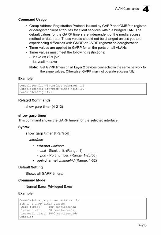
VLAN Commands 4
Command Usage• Group Address Registration Protocol is used by GVRP and GMRP to register or deregister client attributes for client services within a bridged LAN. The default values for the GARP timers are independent of the media access method or data rate. These values should not be changed unless you are experiencing difficulties with GMRP or GVRP registration/deregistration.
• Timer values are applied to GVRP for all the ports on all VLANs. • Timer values must meet the following restrictions:
- leave >= (2 x join) - leaveall > leave
Note: Set GVRP timers on all Layer 2 devices connected in the same network to the same values. Otherwise, GVRP may not operate successfully.
Example
Related Commands
show garp timer (4-213)
show garp timerThis command shows the GARP timers for the selected interface.
Syntax
show garp timer [interface]
interface
• ethernet unit/port - unit - Stack unit. (Range: 1) - port - Port number. (Range: 1-26/50)
• port-channel channel-id (Range: 1-32)
Default Setting
Shows all GARP timers.
Command Mode
Normal Exec, Privileged Exec
Example
Console(config)#interface ethernet 1/1Console(config-if)#garp timer join 100Console(config-if)#
Console#show garp timer ethernet 1/1Eth 1/ 1 GARP timer status: Join timer: 100 centiseconds Leave timer: 60 centiseconds Leaveall timer: 1000 centisecondsConsole#
4-213
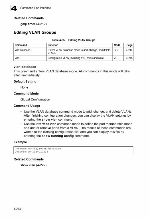
Command Line Interface4
Related Commandsgarp timer (4-212)
Editing VLAN Groups
vlan databaseThis command enters VLAN database mode. All commands in this mode will take effect immediately.
Default Setting
None
Command Mode
Global Configuration
Command Usage
• Use the VLAN database command mode to add, change, and delete VLANs. After finishing configuration changes, you can display the VLAN settings by entering the show vlan command.
• Use the interface vlan command mode to define the port membership mode and add or remove ports from a VLAN. The results of these commands are written to the running-configuration file, and you can display this file by entering the show running-config command.
Example
Related Commands
show vlan (4-222)
Table 4-65 Editing VLAN Groups
Command Function Mode Page
vlan database Enters VLAN database mode to add, change, and delete VLANs
GC 4-214
vlan Configures a VLAN, including VID, name and state VC 4-215
Console(config)#vlan databaseConsole(config-vlan)#
4-214
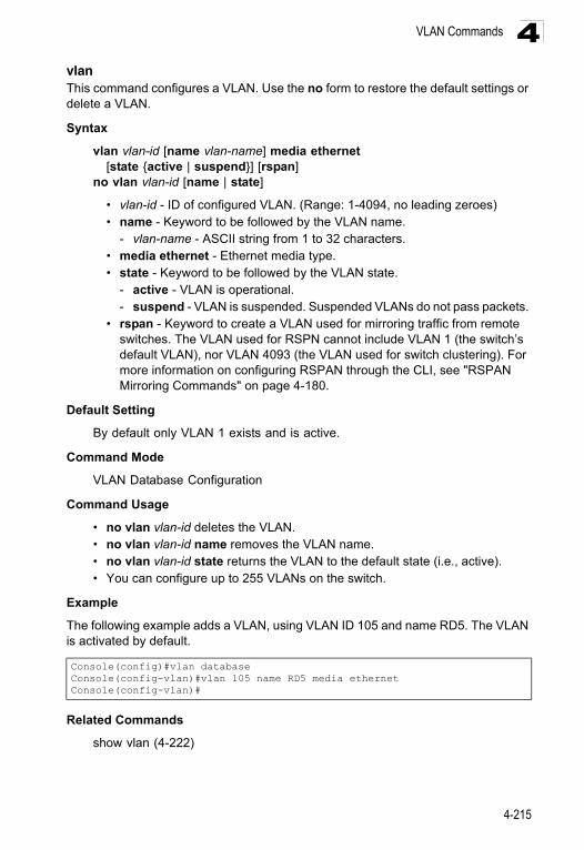
VLAN Commands 4
vlanThis command configures a VLAN. Use the no form to restore the default settings or delete a VLAN.Syntax
vlan vlan-id [name vlan-name] media ethernet [state {active | suspend}] [rspan]
no vlan vlan-id [name | state]
• vlan-id - ID of configured VLAN. (Range: 1-4094, no leading zeroes) • name - Keyword to be followed by the VLAN name.
- vlan-name - ASCII string from 1 to 32 characters. • media ethernet - Ethernet media type. • state - Keyword to be followed by the VLAN state.
- active - VLAN is operational. - suspend - VLAN is suspended. Suspended VLANs do not pass packets.
• rspan - Keyword to create a VLAN used for mirroring traffic from remote switches. The VLAN used for RSPN cannot include VLAN 1 (the switch’s default VLAN), nor VLAN 4093 (the VLAN used for switch clustering). For more information on configuring RSPAN through the CLI, see "RSPAN Mirroring Commands" on page 4-180.
Default Setting
By default only VLAN 1 exists and is active.
Command Mode
VLAN Database Configuration
Command Usage
• no vlan vlan-id deletes the VLAN. • no vlan vlan-id name removes the VLAN name. • no vlan vlan-id state returns the VLAN to the default state (i.e., active). • You can configure up to 255 VLANs on the switch.
Example
The following example adds a VLAN, using VLAN ID 105 and name RD5. The VLAN is activated by default.
Related Commands
show vlan (4-222)
Console(config)#vlan databaseConsole(config-vlan)#vlan 105 name RD5 media ethernetConsole(config-vlan)#
4-215
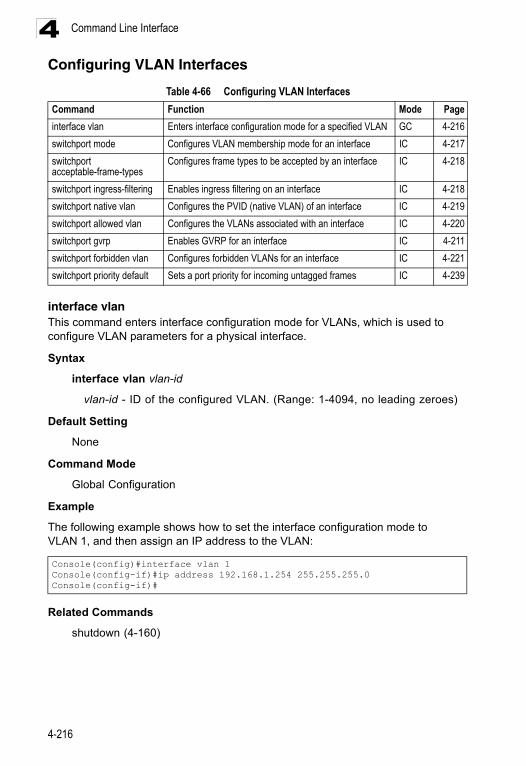
Command Line Interface4
Configuring VLAN Interfacesinterface vlanThis command enters interface configuration mode for VLANs, which is used to configure VLAN parameters for a physical interface.
Syntax
interface vlan vlan-id
vlan-id - ID of the configured VLAN. (Range: 1-4094, no leading zeroes)
Default Setting
None
Command Mode
Global Configuration
Example
The following example shows how to set the interface configuration mode to VLAN 1, and then assign an IP address to the VLAN:
Related Commands
shutdown (4-160)
Table 4-66 Configuring VLAN Interfaces
Command Function Mode Page
interface vlan Enters interface configuration mode for a specified VLAN GC 4-216
switchport mode Configures VLAN membership mode for an interface IC 4-217
switchport acceptable-frame-types
Configures frame types to be accepted by an interface IC 4-218
switchport ingress-filtering Enables ingress filtering on an interface IC 4-218
switchport native vlan Configures the PVID (native VLAN) of an interface IC 4-219
switchport allowed vlan Configures the VLANs associated with an interface IC 4-220
switchport gvrp Enables GVRP for an interface IC 4-211
switchport forbidden vlan Configures forbidden VLANs for an interface IC 4-221
switchport priority default Sets a port priority for incoming untagged frames IC 4-239
Console(config)#interface vlan 1Console(config-if)#ip address 192.168.1.254 255.255.255.0Console(config-if)#
4-216
VLAN Commands 4
switchport modeThis command configures the VLAN membership mode for a port. Use the no form to restore the default.Syntax
switchport mode {access | hybrid | trunk | private-vlan}no switchport mode
• access - Specifies an access VLAN interface. The port transmits and receives untagged frames only.
• trunk - Specifies a port as an end-point for a VLAN trunk. A trunk is a direct link between two switches, so the port transmits tagged frames that identify the source VLAN. Note that frames belonging to the port’s default VLAN (i.e., associated with the PVID) are also transmitted as tagged frames.
• hybrid - Specifies a hybrid VLAN interface. The port may transmit tagged or untagged frames.
• private-vlan - For an explanation of this command see "switchport mode private-vlan" on page 4-232.
Default Setting
All ports are in hybrid mode with the PVID set to VLAN 1.
Command Mode
Interface Configuration (Ethernet, Port Channel)
Example
The following shows how to set the configuration mode to port 1, and then set the switchport mode to hybrid:
Related Commands
switchport acceptable-frame-types (4-218)
Console(config)#interface ethernet 1/1Console(config-if)#switchport mode hybridConsole(config-if)#
4-217
Command Line Interface4
switchport acceptable-frame-types This command configures the acceptable frame types for a port. Use the no form to restore the default.Syntax
switchport acceptable-frame-types {all | tagged}no switchport acceptable-frame-types
• all - The port accepts all frames, tagged or untagged. • tagged - The port only receives tagged frames.
Default Setting
All frame types
Command Mode
Interface Configuration (Ethernet, Port Channel)
Command Usage
When set to receive all frame types, any received frames that are untagged are assigned to the default VLAN.
Example
The following example shows how to restrict the traffic received on port 1 to tagged frames:
Related Commands
switchport mode (4-217)
switchport ingress-filtering This command enables ingress filtering for an interface.
Syntax
[no] switchport ingress-filtering
Default Setting
Enabled
Command Mode
Interface Configuration (Ethernet, Port Channel)
Command Usage
• Ingress filtering only affects tagged frames.
Console(config)#interface ethernet 1/1Console(config-if)#switchport acceptable-frame-types taggedConsole(config-if)#
4-218
VLAN Commands 4
• If ingress filtering is disabled and a port receives frames tagged for VLANs forwhich it is not a member, these frames will be flooded to all other ports (except for those VLANs explicitly forbidden on this port).
• If ingress filtering is enabled and a port receives frames tagged for VLANs for which it is not a member, these frames will be discarded.
• Ingress filtering does not affect VLAN independent BPDU frames, such as GVRP or STA. However, they do affect VLAN dependent BPDU frames, such as GMRP.
Example
The following example shows how to select port 1 and then enable ingress filtering:
switchport native vlanThis command configures the PVID (i.e., default VLAN ID) for a port. Use the no form to restore the default.
Syntax
switchport native vlan vlan-idno switchport native vlan
vlan-id - Default VLAN ID for a port. (Range: 1-4094, no leading zeroes)
Default Setting
VLAN 1
Command Mode
Interface Configuration (Ethernet, Port Channel)
Command Usage
• If an interface is not a member of VLAN 1 and you assign its PVID to this VLAN, the interface will automatically be added to VLAN 1 as an untagged member. For all other VLANs, an interface must first be configured as an untagged member before you can assign its PVID to that group.
• If acceptable frame types is set to all or switchport mode is set to hybrid, the PVID will be inserted into all untagged frames entering the ingress port.
Example
The following example shows how to set the PVID for port 1 to VLAN 3:
Console(config)#interface ethernet 1/1Console(config-if)#switchport ingress-filteringConsole(config-if)#
Console(config)#interface ethernet 1/1Console(config-if)#switchport native vlan 3Console(config-if)#
4-219
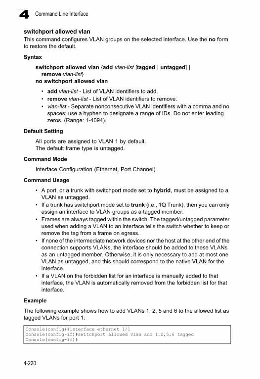
Command Line Interface4
switchport allowed vlanThis command configures VLAN groups on the selected interface. Use the no form to restore the default.Syntax
switchport allowed vlan {add vlan-list [tagged | untagged] | remove vlan-list}
no switchport allowed vlan
• add vlan-list - List of VLAN identifiers to add.• remove vlan-list - List of VLAN identifiers to remove. • vlan-list - Separate nonconsecutive VLAN identifiers with a comma and no
spaces; use a hyphen to designate a range of IDs. Do not enter leading zeros. (Range: 1-4094).
Default Setting
All ports are assigned to VLAN 1 by default.The default frame type is untagged.
Command Mode
Interface Configuration (Ethernet, Port Channel)
Command Usage
• A port, or a trunk with switchport mode set to hybrid, must be assigned to a VLAN as untagged.
• If a trunk has switchport mode set to trunk (i.e., 1Q Trunk), then you can only assign an interface to VLAN groups as a tagged member.
• Frames are always tagged within the switch. The tagged/untagged parameter used when adding a VLAN to an interface tells the switch whether to keep or remove the tag from a frame on egress.
• If none of the intermediate network devices nor the host at the other end of the connection supports VLANs, the interface should be added to these VLANs as an untagged member. Otherwise, it is only necessary to add at most one VLAN as untagged, and this should correspond to the native VLAN for the interface.
• If a VLAN on the forbidden list for an interface is manually added to that interface, the VLAN is automatically removed from the forbidden list for that interface.
Example
The following example shows how to add VLANs 1, 2, 5 and 6 to the allowed list as tagged VLANs for port 1:
Console(config)#interface ethernet 1/1Console(config-if)#switchport allowed vlan add 1,2,5,6 taggedConsole(config-if)#
4-220
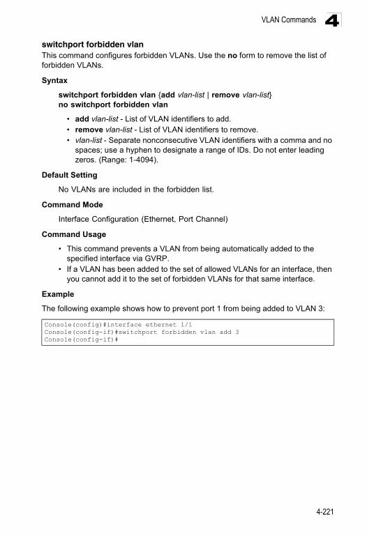
VLAN Commands 4
switchport forbidden vlanThis command configures forbidden VLANs. Use the no form to remove the list of forbidden VLANs.Syntax
switchport forbidden vlan {add vlan-list | remove vlan-list}no switchport forbidden vlan
• add vlan-list - List of VLAN identifiers to add.• remove vlan-list - List of VLAN identifiers to remove.• vlan-list - Separate nonconsecutive VLAN identifiers with a comma and no
spaces; use a hyphen to designate a range of IDs. Do not enter leading zeros. (Range: 1-4094).
Default Setting
No VLANs are included in the forbidden list.
Command Mode
Interface Configuration (Ethernet, Port Channel)
Command Usage
• This command prevents a VLAN from being automatically added to the specified interface via GVRP.
• If a VLAN has been added to the set of allowed VLANs for an interface, then you cannot add it to the set of forbidden VLANs for that same interface.
Example
The following example shows how to prevent port 1 from being added to VLAN 3:
Console(config)#interface ethernet 1/1Console(config-if)#switchport forbidden vlan add 3Console(config-if)#
4-221
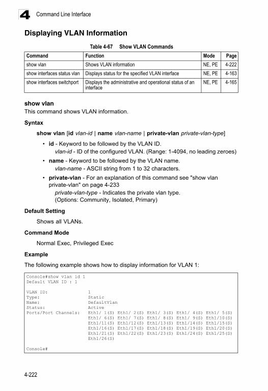
Command Line Interface4
Displaying VLAN Informationshow vlanThis command shows VLAN information.
Syntax
show vlan [id vlan-id | name vlan-name | private-vlan private-vlan-type]
• id - Keyword to be followed by the VLAN ID. vlan-id - ID of the configured VLAN. (Range: 1-4094, no leading zeroes)
• name - Keyword to be followed by the VLAN name. vlan-name - ASCII string from 1 to 32 characters.
• private-vlan - For an explanation of this command see "show vlan private-vlan" on page 4-233
private-vlan-type - Indicates the private vlan type. (Options: Community, Isolated, Primary)
Default Setting
Shows all VLANs.
Command Mode
Normal Exec, Privileged Exec
Example
The following example shows how to display information for VLAN 1:
Table 4-67 Show VLAN Commands
Command Function Mode Page
show vlan Shows VLAN information NE, PE 4-222
show interfaces status vlan Displays status for the specified VLAN interface NE, PE 4-163
show interfaces switchport Displays the administrative and operational status of an interface
NE, PE 4-165
Console#show vlan id 1Default VLAN ID : 1
VLAN ID: 1Type: StaticName: DefaultVlanStatus: ActivePorts/Port Channels: Eth1/ 1(S) Eth1/ 2(S) Eth1/ 3(S) Eth1/ 4(S) Eth1/ 5(S) Eth1/ 6(S) Eth1/ 7(S) Eth1/ 8(S) Eth1/ 9(S) Eth1/10(S) Eth1/11(S) Eth1/12(S) Eth1/13(S) Eth1/14(S) Eth1/15(S) Eth1/16(S) Eth1/17(S) Eth1/18(S) Eth1/19(S) Eth1/20(S) Eth1/21(S) Eth1/22(S) Eth1/23(S) Eth1/24(S) Eth1/25(S) Eth1/26(S)
Console#
4-222
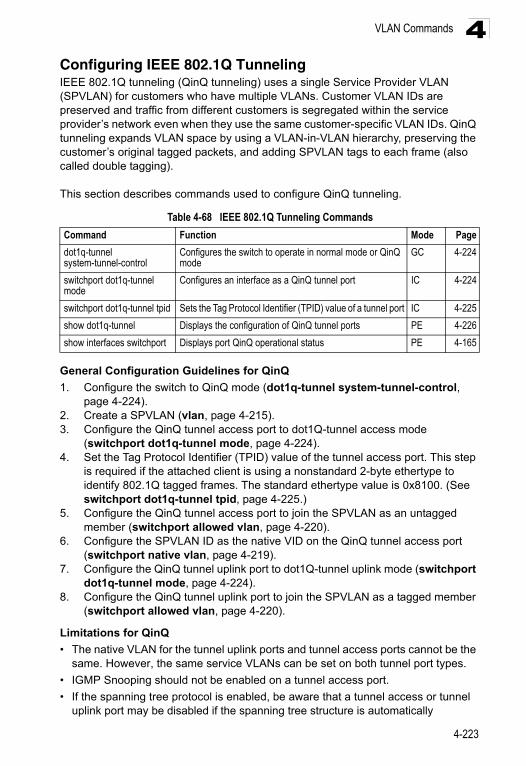
VLAN Commands 4
Configuring IEEE 802.1Q TunnelingIEEE 802.1Q tunneling (QinQ tunneling) uses a single Service Provider VLAN (SPVLAN) for customers who have multiple VLANs. Customer VLAN IDs are preserved and traffic from different customers is segregated within the service provider’s network even when they use the same customer-specific VLAN IDs. QinQ tunneling expands VLAN space by using a VLAN-in-VLAN hierarchy, preserving the customer’s original tagged packets, and adding SPVLAN tags to each frame (also called double tagging).This section describes commands used to configure QinQ tunneling.
General Configuration Guidelines for QinQ
1. Configure the switch to QinQ mode (dot1q-tunnel system-tunnel-control, page 4-224).
2. Create a SPVLAN (vlan, page 4-215).3. Configure the QinQ tunnel access port to dot1Q-tunnel access mode
(switchport dot1q-tunnel mode, page 4-224).4. Set the Tag Protocol Identifier (TPID) value of the tunnel access port. This step
is required if the attached client is using a nonstandard 2-byte ethertype to identify 802.1Q tagged frames. The standard ethertype value is 0x8100. (See switchport dot1q-tunnel tpid, page 4-225.)
5. Configure the QinQ tunnel access port to join the SPVLAN as an untagged member (switchport allowed vlan, page 4-220).
6. Configure the SPVLAN ID as the native VID on the QinQ tunnel access port (switchport native vlan, page 4-219).
7. Configure the QinQ tunnel uplink port to dot1Q-tunnel uplink mode (switchport dot1q-tunnel mode, page 4-224).
8. Configure the QinQ tunnel uplink port to join the SPVLAN as a tagged member (switchport allowed vlan, page 4-220).
Limitations for QinQ
• The native VLAN for the tunnel uplink ports and tunnel access ports cannot be the same. However, the same service VLANs can be set on both tunnel port types.
• IGMP Snooping should not be enabled on a tunnel access port.
• If the spanning tree protocol is enabled, be aware that a tunnel access or tunnel uplink port may be disabled if the spanning tree structure is automatically
Table 4-68 IEEE 802.1Q Tunneling Commands
Command Function Mode Page
dot1q-tunnel system-tunnel-control
Configures the switch to operate in normal mode or QinQ mode
GC 4-224
switchport dot1q-tunnel mode
Configures an interface as a QinQ tunnel port IC 4-224
switchport dot1q-tunnel tpid Sets the Tag Protocol Identifier (TPID) value of a tunnel port IC 4-225
show dot1q-tunnel Displays the configuration of QinQ tunnel ports PE 4-226
show interfaces switchport Displays port QinQ operational status PE 4-165
4-223
Command Line Interface4
reconfigured to overcome a break in the tree. It is therefore advisable to disable spanning tree on these ports.dot1q-tunnel system-tunnel-controlThis command sets the switch to operate in QinQ mode. Use the no form to disable QinQ operating mode.
Syntax
[no] dot1q-tunnel system-tunnel-control
Default Setting
Disabled
Command Mode
Global Configuration
Command Usage
QinQ tunnel mode must be enabled on the switch for QinQ interface settings to be functional.
Example
Related Commands
show dot1q-tunnel (4-226)show interfaces switchport (4-165)
switchport dot1q-tunnel modeThis command configures an interface as a QinQ tunnel port. Use the no form to disable QinQ on the interface.
Syntax
switchport dot1q-tunnel mode <access | uplink>no switchport dot1q-tunnel mode
• access – Sets the port as an 802.1Q tunnel access port.• uplink – Sets the port as an 802.1Q tunnel uplink port.
Default Setting
Disabled
Command Mode
Interface Configuration (Ethernet, Port Channel)
Command Usage
• QinQ tunneling must be enabled on the switch using the dot1q-tunnel system-tunnel-control command before the switchport dot1q-tunnel mode interface command can take effect.
Console(config)#dot1q-tunnel system-tunnel-controlConsole(config)#
4-224
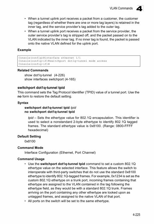
VLAN Commands 4
• When a tunnel uplink port receives a packet from a customer, the customertag (regardless of whether there are one or more tag layers) is retained in the inner tag, and the service provider’s tag added to the outer tag.
• When a tunnel uplink port receives a packet from the service provider, the outer service provider’s tag is stripped off, and the packet passed on to the VLAN indicated by the inner tag. If no inner tag is found, the packet is passed onto the native VLAN defined for the uplink port.
Example
Related Commands
show dot1q-tunnel (4-226)show interfaces switchport (4-165)
switchport dot1q-tunnel tpidThis command sets the Tag Protocol Identifier (TPID) value of a tunnel port. Use the no form to restore the default setting.
Syntax
switchport dot1q-tunnel tpid tpidno switchport dot1q-tunnel tpid
tpid – Sets the ethertype value for 802.1Q encapsulation. This identifier is used to select a nonstandard 2-byte ethertype to identify 802.1Q tagged frames. The standard ethertype value is 0x8100. (Range: 0800-FFFF hexadecimal)
Default Setting
0x8100
Command Mode
Interface Configuration (Ethernet, Port Channel)
Command Usage
• Use the switchport dot1q-tunnel tpid command to set a custom 802.1Q ethertype value on the selected interface. This feature allows the switch to interoperate with third-party switches that do not use the standard 0x8100 ethertype to identify 802.1Q-tagged frames. For example, 0x1234 is set as the custom 802.1Q ethertype on a trunk port, incoming frames containing that ethertype are assigned to the VLAN contained in the tag following the ethertype field, as they would be with a standard 802.1Q trunk. Frames arriving on the port containing any other ethertype are looked upon as untagged frames, and assigned to the native VLAN of that port.
• All ports on the switch will be set to the same ethertype.
Console(config)#interface ethernet 1/1Console(config-if)#switchport dot1q-tunnel mode accessConsole(config-if)#
4-225
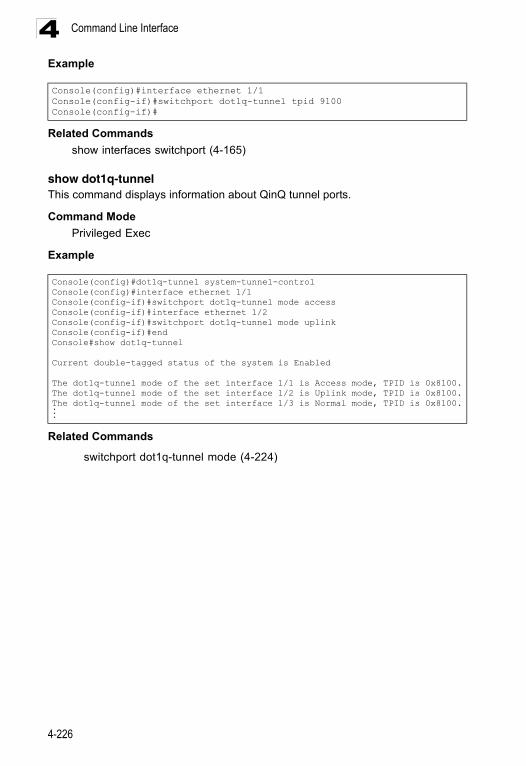
Command Line Interface4
ExampleRelated Commands
show interfaces switchport (4-165)
show dot1q-tunnelThis command displays information about QinQ tunnel ports.
Command Mode
Privileged Exec
Example
Related Commands
switchport dot1q-tunnel mode (4-224)
Console(config)#interface ethernet 1/1Console(config-if)#switchport dot1q-tunnel tpid 9100Console(config-if)#
Console(config)#dot1q-tunnel system-tunnel-controlConsole(config)#interface ethernet 1/1Console(config-if)#switchport dot1q-tunnel mode accessConsole(config-if)#interface ethernet 1/2Console(config-if)#switchport dot1q-tunnel mode uplinkConsole(config-if)#endConsole#show dot1q-tunnel
Current double-tagged status of the system is Enabled
The dot1q-tunnel mode of the set interface 1/1 is Access mode, TPID is 0x8100.The dot1q-tunnel mode of the set interface 1/2 is Uplink mode, TPID is 0x8100.The dot1q-tunnel mode of the set interface 1/3 is Normal mode, TPID is 0x8100....
4-226
VLAN Commands 4
Configuring Port-based Traffic SegmentationIf tighter security is required for passing traffic from different clients through downlink ports on the local network and over uplink ports to the service provider, port-based traffic segmentation can be used to isolate traffic for individual clients.Local traffic belonging to each client is isolated to the allocated downlink ports, and upstream traffic coming from the downlink ports can only be forwarded to, and from, uplink ports.
This section describes commands used to configure traffic segmentation.
pvlanThis command enables port-based traffic segmentation. Use the no form to disable this feature.
Syntax
[no] pvlan
Default Setting
Disabled
Command Mode
Global Configuration
Command Usage
• When traffic segmentation is enabled, the forwarding state for the uplink and downlink ports is shown below.
• When traffic segmentation is disabled, all ports operate in normal forwarding mode based on the settings specified by other functions such as VLANs and spanning tree protocol.
Table 4-69 Traffic Segmentation Commands
Command Function Mode Page
pvlan Enables traffic segmentation GC 4-227
pvlan up-link/down-link Configures uplink/downlink ports for client sessions GC 4-228
show pvlan Displays the configured private VLANS PE 4-228
Table 4-70 Traffic Segmentation Forwarding
DestinationSource
Downlinks Uplinks Normal Ports
Downlink Ports Blocking Forwarding Blocking
Uplink Ports Forwarding Forwarding Forwarding
Normal Ports Forwarding Forwarding Forwarding
4-227
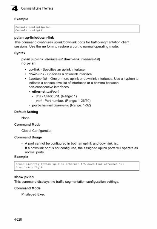
Command Line Interface4
Examplepvlan up-link/down-linkThis command configures uplink/downlink ports for traffic-segmentation client sessions. Use the no form to restore a port to normal operating mode.
Syntax
pvlan [up-link interface-list down-link interface-list]no pvlan
• up-link - Specifies an uplink interface.• down-link - Specifies a downlink interface.• interface-list – One or more uplink or downlink interfaces. Use a hyphen to
indicate a consecutive list of interfaces or a comma between non-consecutive interfaces.• ethernet unit/port
- unit - Stack unit. (Range: 1) - port - Port number. (Range: 1-26/50)
• port-channel channel-id (Range: 1-32)
Default Setting
None
Command Mode
Global Configuration
Command Usage
• A port cannot be configured in both an uplink and downlink list.• If a downlink port is not configured, the assigned uplink ports will operate as
normal ports.Example
show pvlanThis command displays the traffic segmentation configuration settings.
Command Mode
Privileged Exec
Console(config)#pvlanConsole(config)#
Console(config)#pvlan up-link ethernet 1/5 down-link ethernet 1/6Console(config)#
4-228
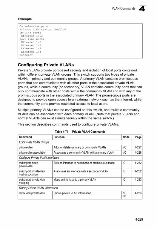
VLAN Commands 4
ExampleConfiguring Private VLANsPrivate VLANs provide port-based security and isolation of local ports contained within different private VLAN groups. This switch supports two types of private VLANs – primary and community groups. A primary VLAN contains promiscuous ports that can communicate with all other ports in the associated private VLAN groups, while a community (or secondary) VLAN contains community ports that can only communicate with other hosts within the community VLAN and with any of the promiscuous ports in the associated primary VLAN. The promiscuous ports are designed to provide open access to an external network such as the Internet, while the community ports provide restricted access to local users.
Multiple primary VLANs can be configured on this switch, and multiple community VLANs can be associated with each primary VLAN. (Note that private VLANs and normal VLANs can exist simultaneously within the same switch.)
This section describes commands used to configure private VLANs.
Console#show pvlanPrivate VLAN status: EnabledUp-link port: Ethernet 1/12Down-link port: Ethernet 1/5 Ethernet 1/6 Ethernet 1/7 Ethernet 1/8Console#
Table 4-71 Private VLAN Commands
Command Function Mode Page
Edit Private VLAN Groups
private-vlan Adds or deletes primary or community VLANs VC 4-227
private-vlan association Associates a community VLAN with a primary VLAN VC 4-228
Configure Private VLAN Interfaces
switchport mode private-vlan
Sets an interface to host mode or promiscuous mode IC 4-232
switchport private-vlan host-association
Associates an interface with a secondary VLAN IC 4-232
switchport private-vlan mapping
Maps an interface to a primary VLAN IC 4-233
Display Private VLAN Information
show vlan private-vlan Shows private VLAN information NE, PE
4-233
4-229
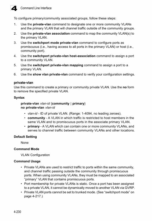
Command Line Interface4
To configure primary/community associated groups, follow these steps:1. Use the private-vlan command to designate one or more community VLANs and the primary VLAN that will channel traffic outside of the community groups.
2. Use the private-vlan association command to map the community VLAN(s) to the primary VLAN.
3. Use the switchport mode private-vlan command to configure ports as promiscuous (i.e., having access to all ports in the primary VLAN) or host (i.e., community port).
4. Use the switchport private-vlan host-association command to assign a port to a community VLAN.
5. Use the switchport private-vlan mapping command to assign a port to a primary VLAN.
6. Use the show vlan private-vlan command to verify your configuration settings.
private-vlanUse this command to create a primary or community private VLAN. Use the no form to remove the specified private VLAN.
Syntax
private-vlan vlan-id {community | primary}no private-vlan vlan-id
• vlan-id - ID of private VLAN. (Range: 1-4094, no leading zeroes).• community - A VLAN in which traffic is restricted to host members in the
same VLAN and to promiscuous ports in the associate primary VLAN.• primary - A VLAN which can contain one or more community VLANs, and
serves to channel traffic between community VLANs and other locations.
Default Setting
None
Command Mode
VLAN Configuration
Command Usage
• Private VLANs are used to restrict traffic to ports within the same community, and channel traffic passing outside the community through promiscuous ports. When using community VLANs, they must be mapped to an associated “primary” VLAN that contains promiscuous ports.
• Port membership for private VLANs is static. Once a port has been assigned to a private VLAN, it cannot be dynamically moved to another VLAN via GVRP.
• Private VLAN ports cannot be set to trunked mode. (See “switchport mode” on page 4-217.)
4-230
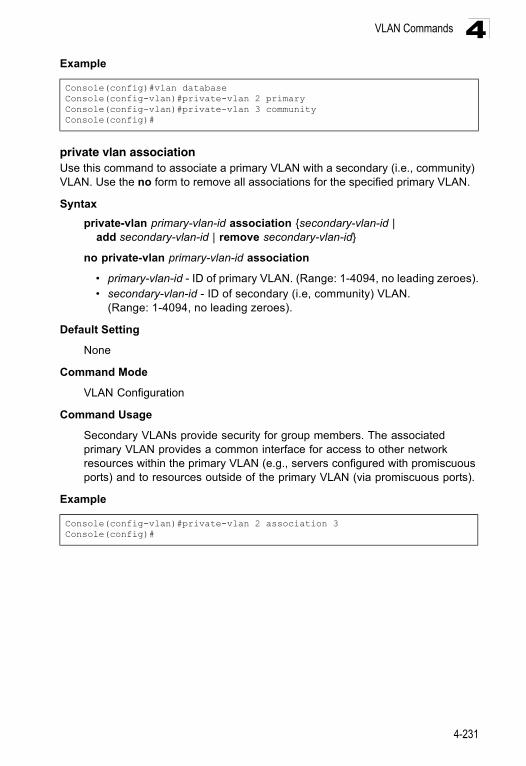
VLAN Commands 4
Exampleprivate vlan associationUse this command to associate a primary VLAN with a secondary (i.e., community) VLAN. Use the no form to remove all associations for the specified primary VLAN.
Syntax
private-vlan primary-vlan-id association {secondary-vlan-id | add secondary-vlan-id | remove secondary-vlan-id}
no private-vlan primary-vlan-id association
• primary-vlan-id - ID of primary VLAN. (Range: 1-4094, no leading zeroes).• secondary-vlan-id - ID of secondary (i.e, community) VLAN.
(Range: 1-4094, no leading zeroes).
Default Setting
None
Command Mode
VLAN Configuration
Command Usage
Secondary VLANs provide security for group members. The associated primary VLAN provides a common interface for access to other network resources within the primary VLAN (e.g., servers configured with promiscuous ports) and to resources outside of the primary VLAN (via promiscuous ports).
Example
Console(config)#vlan databaseConsole(config-vlan)#private-vlan 2 primaryConsole(config-vlan)#private-vlan 3 communityConsole(config)#
Console(config-vlan)#private-vlan 2 association 3Console(config)#
4-231
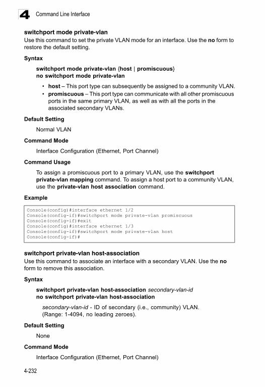
Command Line Interface4
switchport mode private-vlanUse this command to set the private VLAN mode for an interface. Use the no form to restore the default setting.Syntax
switchport mode private-vlan {host | promiscuous}no switchport mode private-vlan
• host – This port type can subsequently be assigned to a community VLAN.• promiscuous – This port type can communicate with all other promiscuous
ports in the same primary VLAN, as well as with all the ports in the associated secondary VLANs.
Default Setting
Normal VLAN
Command Mode
Interface Configuration (Ethernet, Port Channel)
Command Usage
To assign a promiscuous port to a primary VLAN, use the switchport private-vlan mapping command. To assign a host port to a community VLAN, use the private-vlan host association command.
Example
switchport private-vlan host-associationUse this command to associate an interface with a secondary VLAN. Use the no form to remove this association.
Syntax
switchport private-vlan host-association secondary-vlan-idno switchport private-vlan host-association
secondary-vlan-id - ID of secondary (i.e., community) VLAN. (Range: 1-4094, no leading zeroes).
Default Setting
None
Command Mode
Interface Configuration (Ethernet, Port Channel)
Console(config)#interface ethernet 1/2Console(config-if)#switchport mode private-vlan promiscuousConsole(config-if)#exitConsole(config)#interface ethernet 1/3Console(config-if)#switchport mode private-vlan hostConsole(config-if)#
4-232
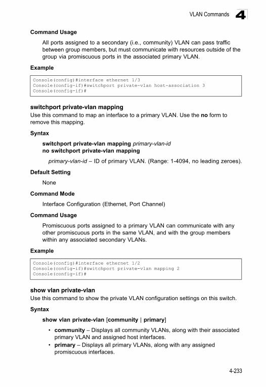
VLAN Commands 4
Command UsageAll ports assigned to a secondary (i.e., community) VLAN can pass traffic between group members, but must communicate with resources outside of the group via promiscuous ports in the associated primary VLAN.
Example
switchport private-vlan mappingUse this command to map an interface to a primary VLAN. Use the no form to remove this mapping.
Syntax
switchport private-vlan mapping primary-vlan-idno switchport private-vlan mapping
primary-vlan-id – ID of primary VLAN. (Range: 1-4094, no leading zeroes).
Default Setting
None
Command Mode
Interface Configuration (Ethernet, Port Channel)
Command Usage
Promiscuous ports assigned to a primary VLAN can communicate with any other promiscuous ports in the same VLAN, and with the group members within any associated secondary VLANs.
Example
show vlan private-vlanUse this command to show the private VLAN configuration settings on this switch.
Syntax
show vlan private-vlan [community | primary]
• community – Displays all community VLANs, along with their associated primary VLAN and assigned host interfaces.
• primary – Displays all primary VLANs, along with any assigned promiscuous interfaces.
Console(config)#interface ethernet 1/3Console(config-if)#switchport private-vlan host-association 3Console(config-if)#
Console(config)#interface ethernet 1/2Console(config-if)#switchport private-vlan mapping 2Console(config-if)#
4-233
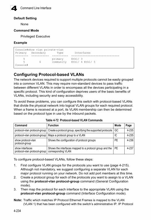
Command Line Interface4
Default SettingNone
Command Mode
Privileged Executive
Example
Configuring Protocol-based VLANsThe network devices required to support multiple protocols cannot be easily grouped into a common VLAN. This may require non-standard devices to pass traffic between different VLANs in order to encompass all the devices participating in a specific protocol. This kind of configuration deprives users of the basic benefits of VLANs, including security and easy accessibility.
To avoid these problems, you can configure this switch with protocol-based VLANs that divide the physical network into logical VLAN groups for each required protocol. When a frame is received at a port, its VLAN membership can then be determined based on the protocol type in use by the inbound packets.
To configure protocol-based VLANs, follow these steps:
1. First configure VLAN groups for the protocols you want to use (page 4-215). Although not mandatory, we suggest configuring a separate VLAN for each major protocol running on your network. Do not add port members at this time.
2. Create a protocol group for each of the protocols you want to assign to a VLAN using the protocol-vlan protocol-group command (General Configuration mode).
3. Then map the protocol for each interface to the appropriate VLAN using the protocol-vlan protocol-group command (Interface Configuration mode).
Note: Traffic which matches IP Protocol Ethernet Frames is mapped to the VLAN (VLAN 1) that has been configured with the switch’s administrative IP. IP Protocol
Console#show vlan private-vlanPrimary Secondary Type Interfaces-------- ----------- ---------- ------------------------------ 5 primary Eth1/ 3 5 6 community Eth1/ 4 Eth1/ 5Console#
Table 4-72 Protocol-based VLAN Commands
Command Function Mode Page
protocol-vlan protocol-group Create a protocol group, specifying the supported protocols GC 4-235
protocol-vlan protocol-group Maps a protocol group to a VLAN IC 4-235
show protocol-vlan protocol-group
Shows the configuration of protocol groups PE 4-236
show interfaces protocol-vlan protocol-group
Shows the interfaces mapped to a protocol group and the corresponding VLAN
PE 4-237
4-234
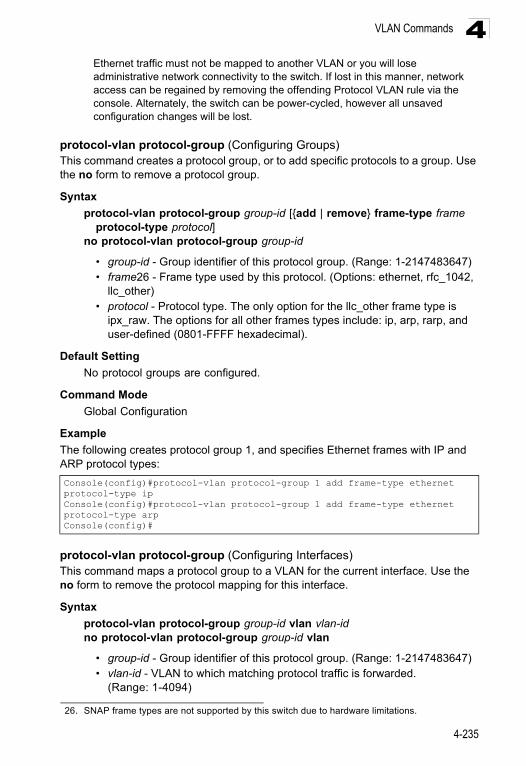
VLAN Commands 4
Ethernet traffic must not be mapped to another VLAN or you will lose administrative network connectivity to the switch. If lost in this manner, network access can be regained by removing the offending Protocol VLAN rule via the console. Alternately, the switch can be power-cycled, however all unsaved configuration changes will be lost.protocol-vlan protocol-group (Configuring Groups)This command creates a protocol group, or to add specific protocols to a group. Use the no form to remove a protocol group.
Syntax
protocol-vlan protocol-group group-id [{add | remove} frame-type frame protocol-type protocol]
no protocol-vlan protocol-group group-id
• group-id - Group identifier of this protocol group. (Range: 1-2147483647)• frame26 - Frame type used by this protocol. (Options: ethernet, rfc_1042,
llc_other)• protocol - Protocol type. The only option for the llc_other frame type is
ipx_raw. The options for all other frames types include: ip, arp, rarp, and user-defined (0801-FFFF hexadecimal).
Default Setting
No protocol groups are configured.
Command Mode
Global Configuration
Example
The following creates protocol group 1, and specifies Ethernet frames with IP and ARP protocol types:
protocol-vlan protocol-group (Configuring Interfaces)This command maps a protocol group to a VLAN for the current interface. Use the no form to remove the protocol mapping for this interface.
Syntax
protocol-vlan protocol-group group-id vlan vlan-idno protocol-vlan protocol-group group-id vlan
• group-id - Group identifier of this protocol group. (Range: 1-2147483647)• vlan-id - VLAN to which matching protocol traffic is forwarded.
(Range: 1-4094)
26. SNAP frame types are not supported by this switch due to hardware limitations.
Console(config)#protocol-vlan protocol-group 1 add frame-type ethernet protocol-type ipConsole(config)#protocol-vlan protocol-group 1 add frame-type ethernet protocol-type arpConsole(config)#
4-235
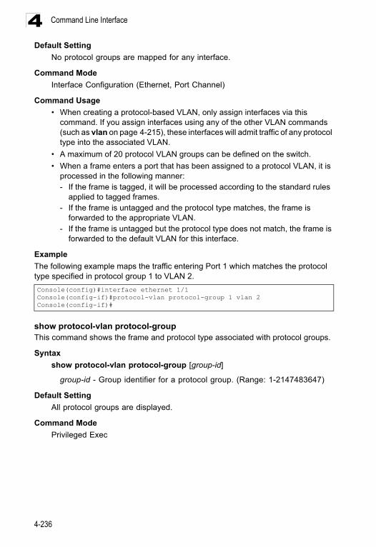
Command Line Interface4
Default SettingNo protocol groups are mapped for any interface.
Command Mode
Interface Configuration (Ethernet, Port Channel)
Command Usage
• When creating a protocol-based VLAN, only assign interfaces via this command. If you assign interfaces using any of the other VLAN commands (such as vlan on page 4-215), these interfaces will admit traffic of any protocol type into the associated VLAN.
• A maximum of 20 protocol VLAN groups can be defined on the switch.
• When a frame enters a port that has been assigned to a protocol VLAN, it is processed in the following manner:- If the frame is tagged, it will be processed according to the standard rules
applied to tagged frames. - If the frame is untagged and the protocol type matches, the frame is
forwarded to the appropriate VLAN.- If the frame is untagged but the protocol type does not match, the frame is
forwarded to the default VLAN for this interface.
Example
The following example maps the traffic entering Port 1 which matches the protocol type specified in protocol group 1 to VLAN 2.
show protocol-vlan protocol-groupThis command shows the frame and protocol type associated with protocol groups.
Syntax
show protocol-vlan protocol-group [group-id]
group-id - Group identifier for a protocol group. (Range: 1-2147483647)
Default Setting
All protocol groups are displayed.
Command Mode
Privileged Exec
Console(config)#interface ethernet 1/1Console(config-if)#protocol-vlan protocol-group 1 vlan 2Console(config-if)#
4-236
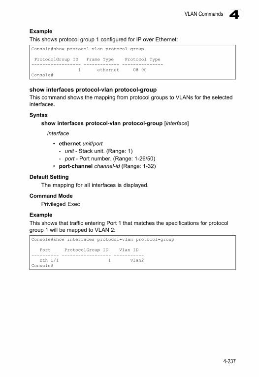
VLAN Commands 4
ExampleThis shows protocol group 1 configured for IP over Ethernet:
show interfaces protocol-vlan protocol-groupThis command shows the mapping from protocol groups to VLANs for the selected interfaces.
Syntax
show interfaces protocol-vlan protocol-group [interface]
interface
• ethernet unit/port - unit - Stack unit. (Range: 1) - port - Port number. (Range: 1-26/50)
• port-channel channel-id (Range: 1-32)
Default Setting
The mapping for all interfaces is displayed.
Command Mode
Privileged Exec
Example
This shows that traffic entering Port 1 that matches the specifications for protocol group 1 will be mapped to VLAN 2:
Console#show protocol-vlan protocol-group
ProtocolGroup ID Frame Type Protocol Type------------------ ------------- --------------- 1 ethernet 08 00Console#
Console#show interfaces protocol-vlan protocol-group
Port ProtocolGroup ID Vlan ID---------- ------------------ ----------- Eth 1/1 1 vlan2Console#
4-237
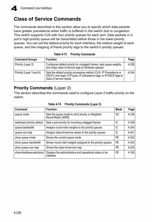
Command Line Interface4
Class of Service CommandsThe commands described in this section allow you to specify which data packets have greater precedence when traffic is buffered in the switch due to congestion. This switch supports CoS with four priority queues for each port. Data packets in a port’s high-priority queue will be transmitted before those in the lower-priority queues. You can set the default priority for each interface, the relative weight of each queue, and the mapping of frame priority tags to the switch’s priority queues.Priority Commands (Layer 2)This section describes the commands used to configure Layer 2 traffic priority on the switch.
Table 4-73 Priority Commands
Command Groups Function Page
Priority (Layer 2) Configures default priority for untagged frames, sets queue weights, and maps class of service tags to hardware queues
4-238
Priority (Layer 3 and 4) Sets the default priority processing method (CoS, IP Precedence or DSCP); and maps TCP ports, IP precedence tags, or IP DSCP tags to class of service values
4-244
Table 4-74 Priority Commands (Layer 2)
Command Function Mode Page
queue mode Sets the queue mode to strict priority or Weighted Round-Robin (WRR)
GC 4-239
switchport priority default Sets a port priority for incoming untagged frames IC 4-239
queue bandwidth Assigns round-robin weights to the priority queues IC 4-240
queue cos map Assigns class-of-service values to the priority queues IC 4-241
show queue mode Shows the current queue mode PE 4-242
show queue bandwidth Shows round-robin weights assigned to the priority queues PE 4-243
show queue cos-map Shows the class-of-service map PE 4-243
show interfaces switchport Displays the administrative and operational status of an interface
PE 4-165
4-238
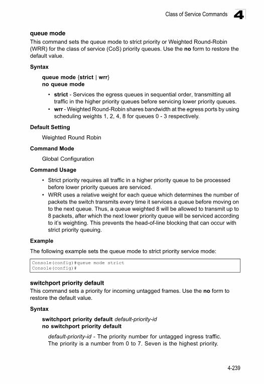
Class of Service Commands 4
queue modeThis command sets the queue mode to strict priority or Weighted Round-Robin (WRR) for the class of service (CoS) priority queues. Use the no form to restore the default value.Syntax
queue mode {strict | wrr}no queue mode
• strict - Services the egress queues in sequential order, transmitting all traffic in the higher priority queues before servicing lower priority queues.
• wrr - Weighted Round-Robin shares bandwidth at the egress ports by using scheduling weights 1, 2, 4, 8 for queues 0 - 3 respectively.
Default Setting
Weighted Round Robin
Command Mode
Global Configuration
Command Usage
• Strict priority requires all traffic in a higher priority queue to be processed before lower priority queues are serviced.
• WRR uses a relative weight for each queue which determines the number of packets the switch transmits every time it services a queue before moving on to the next queue. Thus, a queue weighted 8 will be allowed to transmit up to 8 packets, after which the next lower priority queue will be serviced according to it’s weighting. This prevents the head-of-line blocking that can occur with strict priority queuing.
Example
The following example sets the queue mode to strict priority service mode:
switchport priority defaultThis command sets a priority for incoming untagged frames. Use the no form to restore the default value.
Syntax
switchport priority default default-priority-idno switchport priority default
default-priority-id - The priority number for untagged ingress traffic. The priority is a number from 0 to 7. Seven is the highest priority.
Console(config)#queue mode strictConsole(config)#
4-239
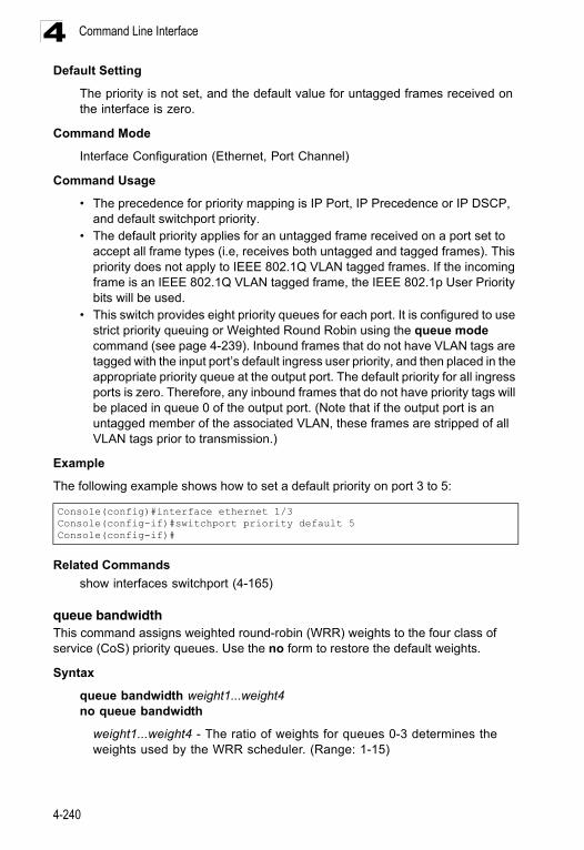
Command Line Interface4
Default SettingThe priority is not set, and the default value for untagged frames received on the interface is zero.
Command Mode
Interface Configuration (Ethernet, Port Channel)
Command Usage
• The precedence for priority mapping is IP Port, IP Precedence or IP DSCP, and default switchport priority.
• The default priority applies for an untagged frame received on a port set to accept all frame types (i.e, receives both untagged and tagged frames). This priority does not apply to IEEE 802.1Q VLAN tagged frames. If the incoming frame is an IEEE 802.1Q VLAN tagged frame, the IEEE 802.1p User Priority bits will be used.
• This switch provides eight priority queues for each port. It is configured to use strict priority queuing or Weighted Round Robin using the queue mode command (see page 4-239). Inbound frames that do not have VLAN tags are tagged with the input port’s default ingress user priority, and then placed in the appropriate priority queue at the output port. The default priority for all ingress ports is zero. Therefore, any inbound frames that do not have priority tags will be placed in queue 0 of the output port. (Note that if the output port is an untagged member of the associated VLAN, these frames are stripped of all VLAN tags prior to transmission.)
Example
The following example shows how to set a default priority on port 3 to 5:
Related Commands
show interfaces switchport (4-165)
queue bandwidth This command assigns weighted round-robin (WRR) weights to the four class of service (CoS) priority queues. Use the no form to restore the default weights.
Syntax
queue bandwidth weight1...weight4no queue bandwidth
weight1...weight4 - The ratio of weights for queues 0-3 determines the weights used by the WRR scheduler. (Range: 1-15)
Console(config)#interface ethernet 1/3Console(config-if)#switchport priority default 5Console(config-if)#
4-240
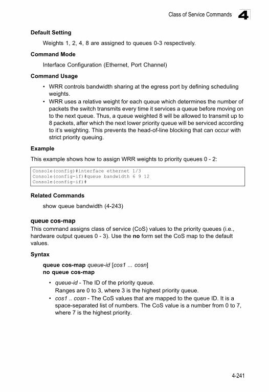
Class of Service Commands 4
Default SettingWeights 1, 2, 4, 8 are assigned to queues 0-3 respectively.
Command Mode
Interface Configuration (Ethernet, Port Channel)
Command Usage
• WRR controls bandwidth sharing at the egress port by defining scheduling weights.
• WRR uses a relative weight for each queue which determines the number of packets the switch transmits every time it services a queue before moving on to the next queue. Thus, a queue weighted 8 will be allowed to transmit up to 8 packets, after which the next lower priority queue will be serviced according to it’s weighting. This prevents the head-of-line blocking that can occur with strict priority queuing.
Example
This example shows how to assign WRR weights to priority queues 0 - 2:
Related Commands
show queue bandwidth (4-243)
queue cos-mapThis command assigns class of service (CoS) values to the priority queues (i.e., hardware output queues 0 - 3). Use the no form set the CoS map to the default values.
Syntax
queue cos-map queue-id [cos1 ... cosn]no queue cos-map
• queue-id - The ID of the priority queue.Ranges are 0 to 3, where 3 is the highest priority queue.
• cos1 .. cosn - The CoS values that are mapped to the queue ID. It is a space-separated list of numbers. The CoS value is a number from 0 to 7, where 7 is the highest priority.
Console(config)#interface ethernet 1/3Console(config-if)#queue bandwidth 6 9 12Console(config-if)#
4-241
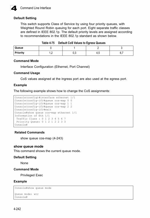
Command Line Interface4
Default SettingThis switch supports Class of Service by using four priority queues, with Weighted Round Robin queuing for each port. Eight separate traffic classes are defined in IEEE 802.1p. The default priority levels are assigned according to recommendations in the IEEE 802.1p standard as shown below.
Command Mode
Interface Configuration (Ethernet, Port Channel)
Command Usage
CoS values assigned at the ingress port are also used at the egress port.
Example
The following example shows how to change the CoS assignments:
Related Commands
show queue cos-map (4-243)
show queue modeThis command shows the current queue mode.
Default Setting
None
Command Mode
Privileged Exec
Example
Table 4-75 Default CoS Values to Egress Queues
Queue 0 1 2 3
Priority 1,2 0,3 4,5 6,7
Console(config)#interface ethernet 1/1Console(config-if)#queue cos-map 0 0Console(config-if)#queue cos-map 1 1Console(config-if)#queue cos-map 2 2Console(config-if)#exitConsole#show queue cos-map ethernet 1/1Information of Eth 1/1 Traffic Class : 0 1 2 3 4 5 6 7 Priority Queue: 0 1 2 1 2 2 3 3Console#
Console#show queue mode
Queue mode: wrrConsole#
4-242
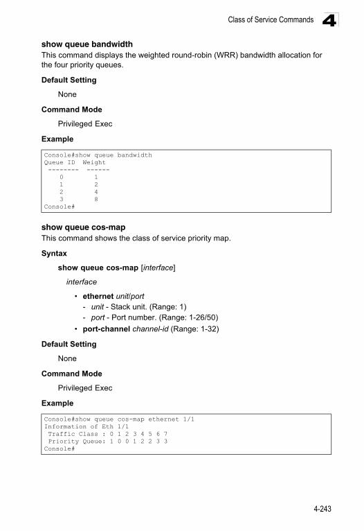
Class of Service Commands 4
show queue bandwidthThis command displays the weighted round-robin (WRR) bandwidth allocation for the four priority queues.Default Setting
None
Command Mode
Privileged Exec
Example
show queue cos-mapThis command shows the class of service priority map.
Syntax
show queue cos-map [interface]
interface
• ethernet unit/port - unit - Stack unit. (Range: 1) - port - Port number. (Range: 1-26/50)
• port-channel channel-id (Range: 1-32)
Default Setting
None
Command Mode
Privileged Exec
Example
Console#show queue bandwidthQueue ID Weight -------- ------ 0 1 1 2 2 4 3 8Console#
Console#show queue cos-map ethernet 1/1Information of Eth 1/1 Traffic Class : 0 1 2 3 4 5 6 7 Priority Queue: 1 0 0 1 2 2 3 3Console#
4-243
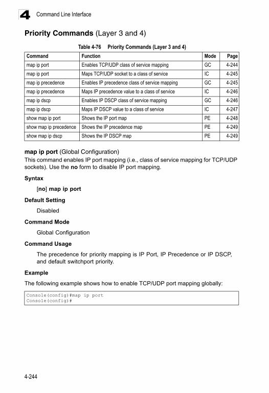
Command Line Interface4
Priority Commands (Layer 3 and 4)map ip port (Global Configuration)This command enables IP port mapping (i.e., class of service mapping for TCP/UDP sockets). Use the no form to disable IP port mapping.
Syntax
[no] map ip port
Default Setting
Disabled
Command Mode
Global Configuration
Command Usage
The precedence for priority mapping is IP Port, IP Precedence or IP DSCP, and default switchport priority.
Example
The following example shows how to enable TCP/UDP port mapping globally:
Table 4-76 Priority Commands (Layer 3 and 4)
Command Function Mode Page
map ip port Enables TCP/UDP class of service mapping GC 4-244
map ip port Maps TCP/UDP socket to a class of service IC 4-245
map ip precedence Enables IP precedence class of service mapping GC 4-245
map ip precedence Maps IP precedence value to a class of service IC 4-246
map ip dscp Enables IP DSCP class of service mapping GC 4-246
map ip dscp Maps IP DSCP value to a class of service IC 4-247
show map ip port Shows the IP port map PE 4-248
show map ip precedence Shows the IP precedence map PE 4-249
show map ip dscp Shows the IP DSCP map PE 4-249
Console(config)#map ip portConsole(config)#
4-244
Class of Service Commands 4
map ip port (Interface Configuration)This command sets IP port priority (i.e., TCP/UDP port priority). Use the no form to remove a specific setting.Syntax
map ip port port-number cos cos-valueno map ip port port-number
• port-number - 16-bit TCP/UDP port number. (Range: 0-65535) • cos-value - Class-of-Service value (Range: 0-7)
Default Setting
None
Command Mode
Interface Configuration (Ethernet, Port Channel)
Command Usage
• The precedence for priority mapping is IP Port, IP Precedence or IP DSCP, and default switchport priority.
• This command sets the IP port priority for all interfaces.
Example
The following example shows how to map HTTP traffic to CoS value 0:
map ip precedence (Global Configuration)This command enables IP precedence mapping (i.e., IP Type of Service). Use the no form to disable IP precedence mapping.
Syntax
[no] map ip precedence
Default Setting
Disabled
Command Mode
Global Configuration
Command Usage
• The precedence for priority mapping is IP Port, IP Precedence or IP DSCP, and default switchport priority.
• IP Precedence and IP DSCP cannot both be enabled. Enabling one of these priority types will automatically disable the other type.
Console(config)#interface ethernet 1/5Console(config-if)#map ip port 80 cos 0Console(config-if)#
4-245
Command Line Interface4
ExampleThe following example shows how to enable IP precedence mapping globally:
map ip precedence (Interface Configuration)This command sets IP precedence priority (i.e., IP Type of Service priority). Use the no form to restore the default table.
Syntax
map ip precedence ip-precedence-value cos cos-valueno map ip precedence
• precedence-value - 3-bit precedence value. (Range: 0-7) • cos-value - Class-of-Service value (Range: 0-7)
Default Setting
The list below shows the default priority mapping.
Command Mode
Interface Configuration (Ethernet, Port Channel)
Command Usage
• The precedence for priority mapping is IP Port, IP Precedence or IP DSCP, and default switchport priority.
• IP Precedence values are mapped to default Class of Service values on a one-to-one basis according to recommendations in the IEEE 802.1p standard, and then subsequently mapped to the eight hardware priority queues.
• This command sets the IP Precedence for all interfaces.
Example
The following example shows how to map IP precedence value 1 to CoS value 0:
map ip dscp (Global Configuration)This command enables IP DSCP mapping (i.e., Differentiated Services Code Point mapping). Use the no form to disable IP DSCP mapping.
Syntax
[no] map ip dscp
Console(config)#map ip precedenceConsole(config)#
Table 4-77 Mapping IP Precedence to CoS Values
IP Precedence Value 0 1 2 3 4 5 6 7
CoS Value 0 1 2 3 4 5 6 7
Console(config)#interface ethernet 1/5Console(config-if)#map ip precedence 1 cos 0Console(config-if)#
4-246
Class of Service Commands 4
Default SettingDisabled
Command Mode
Global Configuration
Command Usage
The precedence for priority mapping is IP DSCP, and default switchport priority.
Example
The following example shows how to enable IP DSCP mapping globally:
map ip dscp (Interface Configuration)This command sets IP DSCP priority (i.e., Differentiated Services Code Point priority). Use the no form to restore the default table.
Syntax
map ip dscp dscp-value cos cos-valueno map ip dscp
• dscp-value - 8-bit DSCP value. (Range: 0-63) • cos-value - Class-of-Service value (Range: 0-7)
Default Setting
The DSCP default values are defined in the following table. Note that all the DSCP values that are not specified are mapped to CoS value 0.
Command Mode
Interface Configuration (Ethernet, Port Channel)
Console(config)#map ip dscpConsole(config)#
Table 4-78 IP DSCP to CoS Vales
IP DSCP Value CoS Value
0 0
8 1
10, 12, 14, 16 2
18, 20, 22, 24 3
26, 28, 30, 32, 34, 36 4
38, 40, 42 5
48 6
46, 56 7
4-247
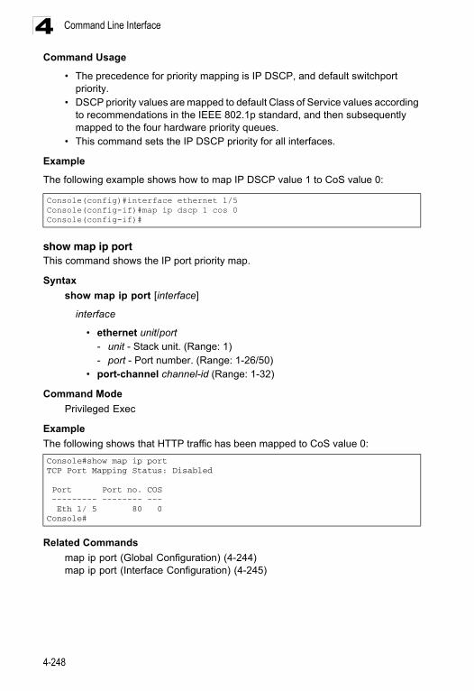
Command Line Interface4
Command Usage• The precedence for priority mapping is IP DSCP, and default switchport priority.
• DSCP priority values are mapped to default Class of Service values according to recommendations in the IEEE 802.1p standard, and then subsequently mapped to the four hardware priority queues.
• This command sets the IP DSCP priority for all interfaces.
Example
The following example shows how to map IP DSCP value 1 to CoS value 0:
show map ip portThis command shows the IP port priority map.
Syntax
show map ip port [interface]
interface
• ethernet unit/port - unit - Stack unit. (Range: 1) - port - Port number. (Range: 1-26/50)
• port-channel channel-id (Range: 1-32)
Command Mode
Privileged Exec
Example
The following shows that HTTP traffic has been mapped to CoS value 0:
Related Commands
map ip port (Global Configuration) (4-244)map ip port (Interface Configuration) (4-245)
Console(config)#interface ethernet 1/5Console(config-if)#map ip dscp 1 cos 0Console(config-if)#
Console#show map ip portTCP Port Mapping Status: Disabled
Port Port no. COS --------- -------- --- Eth 1/ 5 80 0Console#
4-248
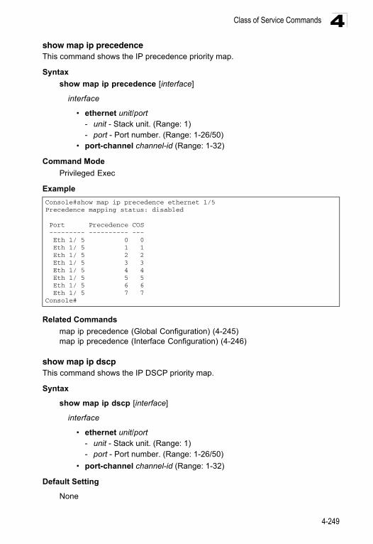
Class of Service Commands 4
show map ip precedenceThis command shows the IP precedence priority map.Syntax
show map ip precedence [interface]
interface
• ethernet unit/port - unit - Stack unit. (Range: 1) - port - Port number. (Range: 1-26/50)
• port-channel channel-id (Range: 1-32)
Command Mode
Privileged Exec
Example
Related Commands
map ip precedence (Global Configuration) (4-245)map ip precedence (Interface Configuration) (4-246)
show map ip dscpThis command shows the IP DSCP priority map.
Syntax
show map ip dscp [interface]
interface
• ethernet unit/port - unit - Stack unit. (Range: 1) - port - Port number. (Range: 1-26/50)
• port-channel channel-id (Range: 1-32)
Default Setting
None
Console#show map ip precedence ethernet 1/5Precedence mapping status: disabled
Port Precedence COS --------- ---------- --- Eth 1/ 5 0 0 Eth 1/ 5 1 1 Eth 1/ 5 2 2 Eth 1/ 5 3 3 Eth 1/ 5 4 4 Eth 1/ 5 5 5 Eth 1/ 5 6 6 Eth 1/ 5 7 7Console#
4-249
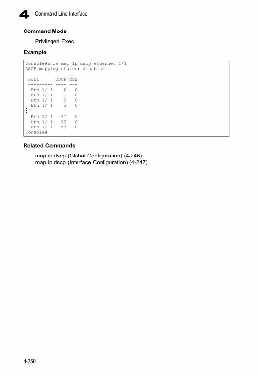
Command Line Interface4
Command ModePrivileged Exec
Example
Related Commands
map ip dscp (Global Configuration) (4-246)map ip dscp (Interface Configuration) (4-247)
Console#show map ip dscp ethernet 1/1DSCP mapping status: disabled
Port DSCP COS --------- ---- --- Eth 1/ 1 0 0 Eth 1/ 1 1 0 Eth 1/ 1 2 0 Eth 1/ 1 3 0... Eth 1/ 1 61 0 Eth 1/ 1 62 0 Eth 1/ 1 63 0Console#
4-250
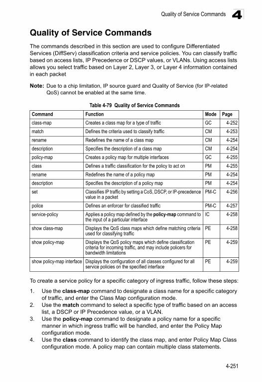
Quality of Service Commands 4
Quality of Service CommandsThe commands described in this section are used to configure Differentiated Services (DiffServ) classification criteria and service policies. You can classify traffic based on access lists, IP Precedence or DSCP values, or VLANs. Using access lists allows you select traffic based on Layer 2, Layer 3, or Layer 4 information contained in each packetNote: Due to a chip limitation, IP source guard and Quality of Service (for IP-related QoS) cannot be enabled at the same time.
To create a service policy for a specific category of ingress traffic, follow these steps:
1. Use the class-map command to designate a class name for a specific category of traffic, and enter the Class Map configuration mode.
2. Use the match command to select a specific type of traffic based on an access list, a DSCP or IP Precedence value, or a VLAN.
3. Use the policy-map command to designate a policy name for a specific manner in which ingress traffic will be handled, and enter the Policy Map configuration mode.
4. Use the class command to identify the class map, and enter Policy Map Class configuration mode. A policy map can contain multiple class statements.
Table 4-79 Quality of Service Commands
Command Function Mode Page
class-map Creates a class map for a type of traffic GC 4-252
match Defines the criteria used to classify traffic CM 4-253
rename Redefines the name of a class map CM 4-254
description Specifies the description of a class map CM 4-254
policy-map Creates a policy map for multiple interfaces GC 4-255
class Defines a traffic classification for the policy to act on PM 4-255
rename Redefines the name of a policy map PM 4-254
description Specifies the description of a policy map PM 4-254
set Classifies IP traffic by setting a CoS, DSCP, or IP-precedence value in a packet
PM-C 4-256
police Defines an enforcer for classified traffic PM-C 4-257
service-policy Applies a policy map defined by the policy-map command to the input of a particular interface
IC 4-258
show class-map Displays the QoS class maps which define matching criteria used for classifying traffic
PE 4-258
show policy-map Displays the QoS policy maps which define classification criteria for incoming traffic, and may include policers for bandwidth limitations
PE 4-259
show policy-map interface Displays the configuration of all classes configured for all service policies on the specified interface
PE 4-259
4-251
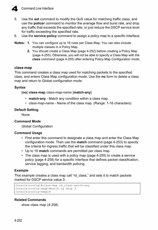
Command Line Interface4
5. Use the set command to modify the QoS value for matching traffic class, anduse the policer command to monitor the average flow and burst rate, and drop any traffic that exceeds the specified rate, or just reduce the DSCP service level for traffic exceeding the specified rate.
6. Use the service-policy command to assign a policy map to a specific interface.
Notes: 1. You can configure up to 16 rules per Class Map. You can also include multiple classes in a Policy Map.
2. You should create a Class Map (page 4-252) before creating a Policy Map (page 4-255). Otherwise, you will not be able to specify a Class Map with the class command (page 4-255) after entering Policy-Map Configuration mode.
class-mapThis command creates a class map used for matching packets to the specified class, and enters Class Map configuration mode. Use the no form to delete a class map and return to Global configuration mode.
Syntax
[no] class-map class-map-name [match-any]
• match-any - Match any condition within a class map. • class-map-name - Name of the class map. (Range: 1-16 characters)
Default Setting
None
Command Mode
Global Configuration
Command Usage
• First enter this command to designate a class map and enter the Class Map configuration mode. Then use the match command (page 4-253) to specify the criteria for ingress traffic that will be classified under this class map.
• Up to 16 match commands are permitted per class map.• The class map is used with a policy map (page 4-255) to create a service
policy (page 4-258) for a specific interface that defines packet classification, service tagging, and bandwidth policing.
Example
This example creates a class map call “rd_class,” and sets it to match packets marked for DSCP service value 3:
Related Commands
show class map (4-258)
Console(config)#class-map rd_class match-any Console(config-cmap)#match ip dscp 3Console(config-cmap)#
4-252
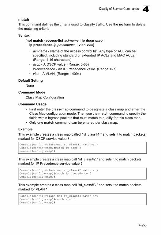
Quality of Service Commands 4
matchThis command defines the criteria used to classify traffic. Use the no form to delete the matching criteria.Syntax
[no] match {access-list acl-name | ip dscp dscp | ip precedence ip-precedence | vlan vlan}
• acl-name - Name of the access control list. Any type of ACL can be specified, including standard or extended IP ACLs and MAC ACLs. (Range: 1-16 characters)
• dscp - A DSCP value. (Range: 0-63)• ip-precedence - An IP Precedence value. (Range: 0-7) • vlan - A VLAN. (Range:1-4094)
Default Setting
None
Command Mode
Class Map Configuration
Command Usage
• First enter the class-map command to designate a class map and enter the Class Map configuration mode. Then use the match command to specify the fields within ingress packets that must match to qualify for this class map.
• Only one match command can be entered per class map.
Example
This example creates a class map called “rd_class#1,” and sets it to match packets marked for DSCP service value 3:
This example creates a class map call “rd_class#2,” and sets it to match packets marked for IP Precedence service value 5:
This example creates a class map call “rd_class#3,” and sets it to match packets marked for VLAN 1:
Console(config)#class-map rd_class#1 match-anyConsole(config-cmap)#match ip dscp 3Console(config-cmap)#
Console(config)#class-map rd_class#2 match-any Console(config-cmap)#match ip precedence 5Console(config-cmap)#
Console(config)#class-map rd_class#3 match-any Console(config-cmap)#match vlan 1Console(config-cmap)#
4-253
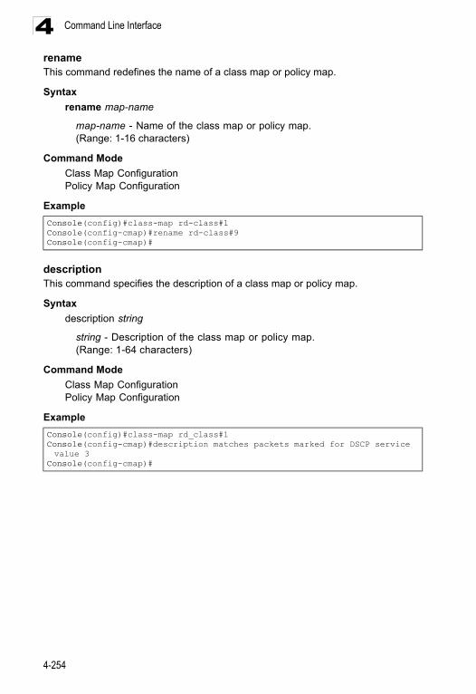
Command Line Interface4
renameThis command redefines the name of a class map or policy map.Syntax
rename map-name
map-name - Name of the class map or policy map. (Range: 1-16 characters)
Command Mode
Class Map ConfigurationPolicy Map Configuration
Example
description This command specifies the description of a class map or policy map.
Syntax
description string
string - Description of the class map or policy map. (Range: 1-64 characters)
Command Mode
Class Map ConfigurationPolicy Map Configuration
Example
Console(config)#class-map rd-class#1Console(config-cmap)#rename rd-class#9Console(config-cmap)#
Console(config)#class-map rd_class#1Console(config-cmap)#description matches packets marked for DSCP service value 3
Console(config-cmap)#
4-254
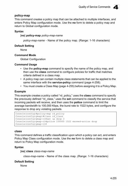
Quality of Service Commands 4
policy-mapThis command creates a policy map that can be attached to multiple interfaces, and enters Policy Map configuration mode. Use the no form to delete a policy map and return to Global configuration mode.Syntax
[no] policy-map policy-map-name
policy-map-name - Name of the policy map. (Range: 1-16 characters)
Default Setting
None
Command Mode
Global Configuration
Command Usage
• Use the policy-map command to specify the name of the policy map, and then use the class command to configure policies for traffic that matches criteria defined in a class map.
• A policy map can contain multiple class statements that can be applied to the same interface with the service-policy command (page 4-258).
• You must create a Class Map (page 4-255) before assigning it to a Policy Map.
Example
This example creates a policy called “rd_policy,” uses the class command to specify the previously defined “rd_class,” uses the set command to classify the service that incoming packets will receive, and then uses the police command to limit the average bandwidth to 100,000 Kbps, the burst rate to 1522 bytes, and configure the response to drop any violating packets.
classThis command defines a traffic classification upon which a policy can act, and enters Policy Map Class configuration mode. Use the no form to delete a class map and return to Policy Map configuration mode.
Syntax
[no] class class-map-name
class-map-name - Name of the class map. (Range: 1-16 characters)
Default Setting
None
Console(config)#policy-map rd_policyConsole(config-pmap)#class rd_classConsole(config-pmap-c)#set ip dscp 3Console(config-pmap-c)#police 100000 1522 exceed-action dropConsole(config-pmap-c)#
4-255
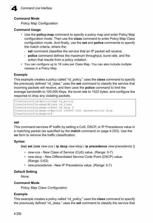
Command Line Interface4
Command ModePolicy Map Configuration
Command Usage
• Use the policy-map command to specify a policy map and enter Policy Map configuration mode. Then use the class command to enter Policy Map Class configuration mode. And finally, use the set and police commands to specify the match criteria, where the:- set command classifies the service that an IP packet will receive.- police command defines the maximum throughput, burst rate, and the
action that results from a policy violation.• You can configure up to 16 rules per Class Map. You can also include multiple
classes in a Policy Map.
Example
This example creates a policy called “rd_policy,” uses the class command to specify the previously defined “rd_class,” uses the set command to classify the service that incoming packets will receive, and then uses the police command to limit the average bandwidth to 100,000 Kbps, the burst rate to 1522 bytes, and configure the response to drop any violating packets.
setThis command services IP traffic by setting a CoS, DSCP, or IP Precedence value in a matching packet (as specified by the match command on page 4-253). Use the no form to remove the traffic classification.
Syntax
[no] set {cos new-cos | ip dscp new-dscp | ip precedence new-precedence |}
• new-cos - New Class of Service (CoS) value. (Range: 0-7)• new-dscp - New Differentiated Service Code Point (DSCP) value.
(Range: 0-63)• new-precedence - New IP Precedence value. (Range: 0-7)
Default Setting
None
Command Mode
Policy Map Class Configuration
Example
This example creates a policy called “rd_policy,” uses the class command to specify the previously defined “rd_class,” uses the set command to classify the service that
Console(config)#policy-map rd_policyConsole(config-pmap)#class rd_classConsole(config-pmap-c)#set ip dscp 3Console(config-pmap-c)#police 100000 1522 exceed-action dropConsole(config-pmap-c)#
4-256
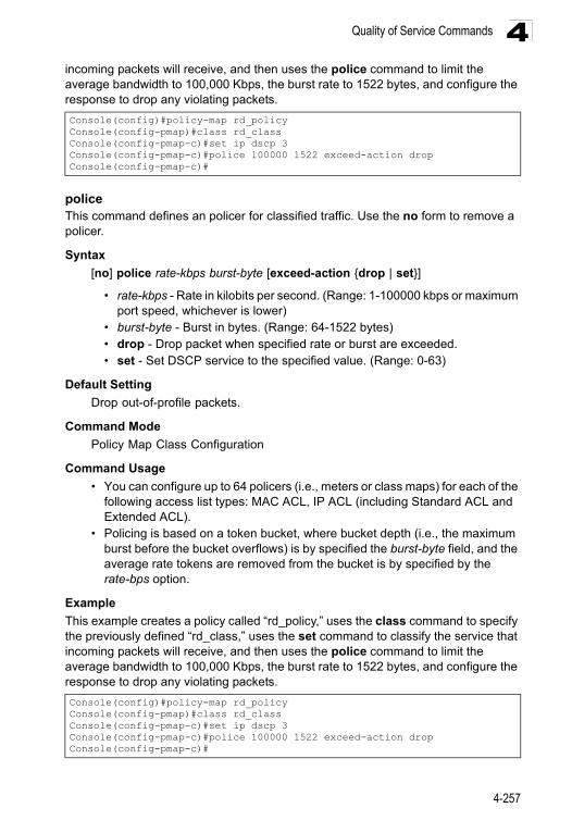
Quality of Service Commands 4
incoming packets will receive, and then uses the police command to limit the average bandwidth to 100,000 Kbps, the burst rate to 1522 bytes, and configure the response to drop any violating packets.policeThis command defines an policer for classified traffic. Use the no form to remove a policer.
Syntax
[no] police rate-kbps burst-byte [exceed-action {drop | set}]
• rate-kbps - Rate in kilobits per second. (Range: 1-100000 kbps or maximum port speed, whichever is lower)
• burst-byte - Burst in bytes. (Range: 64-1522 bytes)• drop - Drop packet when specified rate or burst are exceeded.• set - Set DSCP service to the specified value. (Range: 0-63)
Default Setting
Drop out-of-profile packets.
Command Mode
Policy Map Class Configuration
Command Usage
• You can configure up to 64 policers (i.e., meters or class maps) for each of the following access list types: MAC ACL, IP ACL (including Standard ACL and Extended ACL).
• Policing is based on a token bucket, where bucket depth (i.e., the maximum burst before the bucket overflows) is by specified the burst-byte field, and the average rate tokens are removed from the bucket is by specified by the rate-bps option.
Example
This example creates a policy called “rd_policy,” uses the class command to specify the previously defined “rd_class,” uses the set command to classify the service that incoming packets will receive, and then uses the police command to limit the average bandwidth to 100,000 Kbps, the burst rate to 1522 bytes, and configure the response to drop any violating packets.
Console(config)#policy-map rd_policyConsole(config-pmap)#class rd_classConsole(config-pmap-c)#set ip dscp 3Console(config-pmap-c)#police 100000 1522 exceed-action dropConsole(config-pmap-c)#
Console(config)#policy-map rd_policyConsole(config-pmap)#class rd_classConsole(config-pmap-c)#set ip dscp 3Console(config-pmap-c)#police 100000 1522 exceed-action dropConsole(config-pmap-c)#
4-257
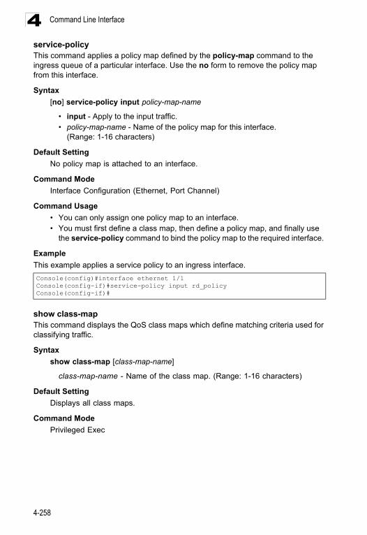
Command Line Interface4
service-policyThis command applies a policy map defined by the policy-map command to the ingress queue of a particular interface. Use the no form to remove the policy map from this interface.Syntax
[no] service-policy input policy-map-name
• input - Apply to the input traffic.• policy-map-name - Name of the policy map for this interface.
(Range: 1-16 characters)
Default Setting
No policy map is attached to an interface.
Command Mode
Interface Configuration (Ethernet, Port Channel)
Command Usage
• You can only assign one policy map to an interface.• You must first define a class map, then define a policy map, and finally use
the service-policy command to bind the policy map to the required interface.
Example
This example applies a service policy to an ingress interface.
show class-mapThis command displays the QoS class maps which define matching criteria used for classifying traffic.
Syntax
show class-map [class-map-name]
class-map-name - Name of the class map. (Range: 1-16 characters)
Default Setting
Displays all class maps.
Command Mode
Privileged Exec
Console(config)#interface ethernet 1/1 Console(config-if)#service-policy input rd_policyConsole(config-if)#
4-258
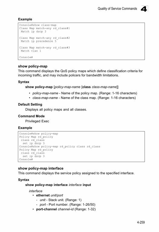
Quality of Service Commands 4
Exampleshow policy-map This command displays the QoS policy maps which define classification criteria for incoming traffic, and may include policers for bandwidth limitations.
Syntax
show policy-map [policy-map-name [class class-map-name]]
• policy-map-name - Name of the policy map. (Range: 1-16 characters)• class-map-name - Name of the class map. (Range: 1-16 characters)
Default Setting
Displays all policy maps and all classes.
Command Mode
Privileged Exec
Example
show policy-map interfaceThis command displays the service policy assigned to the specified interface.
Syntax
show policy-map interface interface input
interface • ethernet unit/port
- unit - Stack unit. (Range: 1) - port - Port number. (Range: 1-26/50)
• port-channel channel-id (Range: 1-32)
Console#show class-map Class Map match-any rd_class#1 Match ip dscp 3
Class Map match-any rd_class#2 Match ip precedence 5
Class Map match-any rd_class#3 Match vlan 1
Console#
Console#show policy-map Policy Map rd_policy class rd_class set ip dscp 3 Console#show policy-map rd_policy class rd_classPolicy Map rd_policy class rd_class set ip dscp 3 Console#
4-259
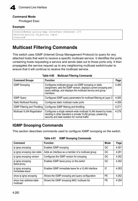
Command Line Interface4
Command ModePrivileged Exec
Example
Multicast Filtering CommandsThis switch uses IGMP (Internet Group Management Protocol) to query for any attached hosts that want to receive a specific multicast service. It identifies the ports containing hosts requesting a service and sends data out to those ports only. It then propagates the service request up to any neighboring multicast switch/router to ensure that it will continue to receive the multicast service.
IGMP Snooping CommandsThis section describes commands used to configure IGMP snooping on the switch.
Console#show policy-map interface ethernet 1/5Service-policy rd_policy inputConsole#
Table 4-80 Multicast Filtering Commands
Command Groups Function Page
IGMP Snooping Configures multicast groups via IGMP snooping or static assignment, sets the IGMP version, displays current snooping and query settings, and displays the multicast service and group members
4-260
IGMP Query Configures IGMP query parameters for multicast filtering at Layer 2 4-265
Static Multicast Routing Configures static multicast router ports 4-269
IGMP Filtering and Throttling Configures IGMP filtering and throttling 4-271
Multicast VLAN Registration Configures a single network-wide multicast VLAN shared by hosts residing in other standard or private VLAN groups, preserving security and data isolation for normal traffic
4-278
Table 4-81 IGMP Snooping Commands
Command Function Mode Page
ip igmp snooping Enables IGMP snooping GC 4-261
ip igmp snooping vlan static Adds an interface as a member of a multicast group GC 4-261
ip igmp snooping version Configures the IGMP version for snooping GC 4-262
ip igmp snooping leave-proxy
Enables IGMP leave proxy on the switch GC 4-262
ip igmp snooping immediate-leave
Enables IGMP immediate leave for a VLAN interface IC 4-263
show ip igmp snooping Shows the IGMP snooping and query configuration PE 4-262
show mac-address-table multicast
Shows the IGMP snooping MAC multicast list PE 4-264
4-260
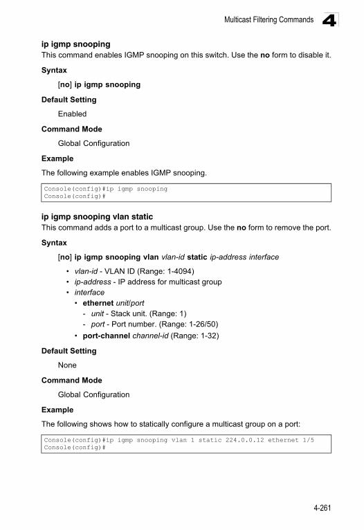
Multicast Filtering Commands 4
ip igmp snoopingThis command enables IGMP snooping on this switch. Use the no form to disable it.Syntax
[no] ip igmp snooping
Default Setting
Enabled
Command Mode
Global Configuration
Example
The following example enables IGMP snooping.
ip igmp snooping vlan staticThis command adds a port to a multicast group. Use the no form to remove the port.
Syntax
[no] ip igmp snooping vlan vlan-id static ip-address interface
• vlan-id - VLAN ID (Range: 1-4094) • ip-address - IP address for multicast group • interface
• ethernet unit/port - unit - Stack unit. (Range: 1) - port - Port number. (Range: 1-26/50)
• port-channel channel-id (Range: 1-32)
Default Setting
None
Command Mode
Global Configuration
Example
The following shows how to statically configure a multicast group on a port:
Console(config)#ip igmp snoopingConsole(config)#
Console(config)#ip igmp snooping vlan 1 static 224.0.0.12 ethernet 1/5Console(config)#
4-261
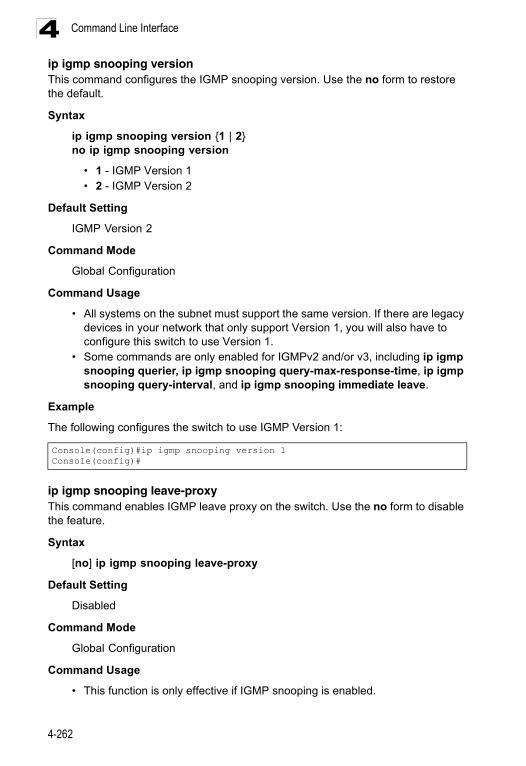
Command Line Interface4
ip igmp snooping versionThis command configures the IGMP snooping version. Use the no form to restore the default.Syntax
ip igmp snooping version {1 | 2}no ip igmp snooping version
• 1 - IGMP Version 1 • 2 - IGMP Version 2
Default Setting
IGMP Version 2
Command Mode
Global Configuration
Command Usage
• All systems on the subnet must support the same version. If there are legacy devices in your network that only support Version 1, you will also have to configure this switch to use Version 1.
• Some commands are only enabled for IGMPv2 and/or v3, including ip igmp snooping querier, ip igmp snooping query-max-response-time, ip igmp snooping query-interval, and ip igmp snooping immediate leave.
Example
The following configures the switch to use IGMP Version 1:
ip igmp snooping leave-proxyThis command enables IGMP leave proxy on the switch. Use the no form to disable the feature.
Syntax
[no] ip igmp snooping leave-proxy
Default Setting
Disabled
Command Mode
Global Configuration
Command Usage
• This function is only effective if IGMP snooping is enabled.
Console(config)#ip igmp snooping version 1Console(config)#
4-262
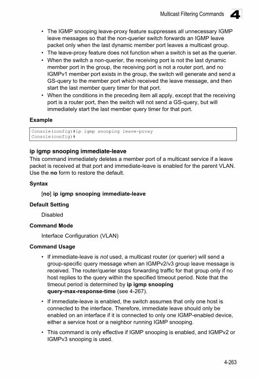
Multicast Filtering Commands 4
• The IGMP snooping leave-proxy feature suppresses all unnecessary IGMPleave messages so that the non-querier switch forwards an IGMP leave packet only when the last dynamic member port leaves a multicast group.
• The leave-proxy feature does not function when a switch is set as the querier.• When the switch a non-querier, the receiving port is not the last dynamic
member port in the group, the receiving port is not a router port, and no IGMPv1 member port exists in the group, the switch will generate and send a GS-query to the member port which received the leave message, and then start the last member query timer for that port.
• When the conditions in the preceding item all apply, except that the receiving port is a router port, then the switch will not send a GS-query, but will immediately start the last member query timer for that port.
Example
ip igmp snooping immediate-leaveThis command immediately deletes a member port of a multicast service if a leave packet is received at that port and immediate-leave is enabled for the parent VLAN. Use the no form to restore the default.
Syntax
[no] ip igmp snooping immediate-leave
Default Setting
Disabled
Command Mode
Interface Configuration (VLAN)
Command Usage
• If immediate-leave is not used, a multicast router (or querier) will send a group-specific query message when an IGMPv2/v3 group leave message is received. The router/querier stops forwarding traffic for that group only if no host replies to the query within the specified timeout period. Note that the timeout period is determined by ip igmp snooping query-max-response-time (see 4-267).
• If immediate-leave is enabled, the switch assumes that only one host is connected to the interface. Therefore, immediate leave should only be enabled on an interface if it is connected to only one IGMP-enabled device, either a service host or a neighbor running IGMP snooping.
• This command is only effective if IGMP snooping is enabled, and IGMPv2 or IGMPv3 snooping is used.
Console(config)#ip igmp snooping leave-proxyConsole(config)#
4-263
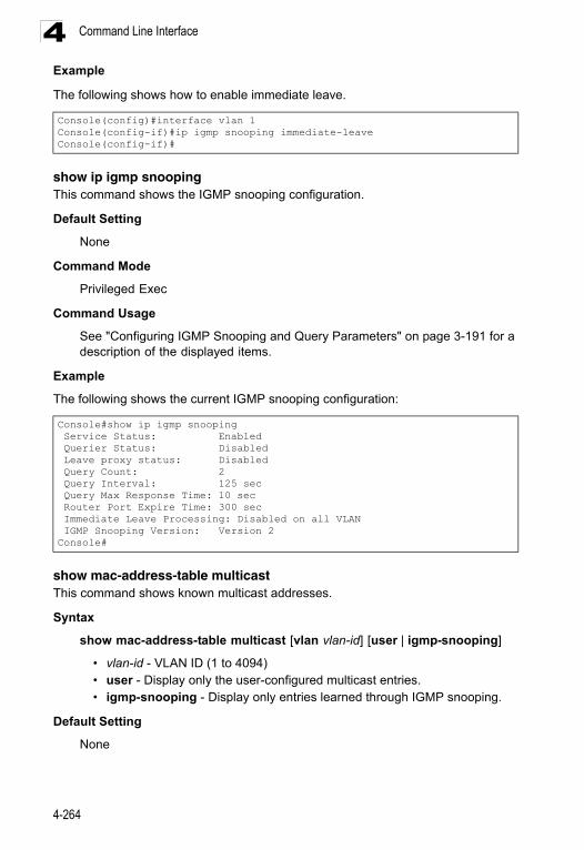
Command Line Interface4
ExampleThe following shows how to enable immediate leave.
show ip igmp snoopingThis command shows the IGMP snooping configuration.
Default Setting
None
Command Mode
Privileged Exec
Command Usage
See "Configuring IGMP Snooping and Query Parameters" on page 3-191 for a description of the displayed items.
Example
The following shows the current IGMP snooping configuration:
show mac-address-table multicast This command shows known multicast addresses.
Syntax
show mac-address-table multicast [vlan vlan-id] [user | igmp-snooping]
• vlan-id - VLAN ID (1 to 4094) • user - Display only the user-configured multicast entries. • igmp-snooping - Display only entries learned through IGMP snooping.
Default Setting
None
Console(config)#interface vlan 1Console(config-if)#ip igmp snooping immediate-leaveConsole(config-if)#
Console#show ip igmp snooping Service Status: Enabled Querier Status: Disabled Leave proxy status: Disabled Query Count: 2 Query Interval: 125 sec Query Max Response Time: 10 sec Router Port Expire Time: 300 sec Immediate Leave Processing: Disabled on all VLAN IGMP Snooping Version: Version 2Console#
4-264
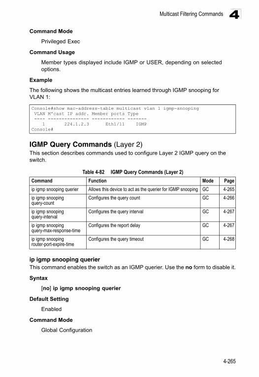
Multicast Filtering Commands 4
Command ModePrivileged Exec
Command Usage
Member types displayed include IGMP or USER, depending on selected options.
Example
The following shows the multicast entries learned through IGMP snooping for VLAN 1:
IGMP Query Commands (Layer 2)This section describes commands used to configure Layer 2 IGMP query on the switch.
ip igmp snooping querierThis command enables the switch as an IGMP querier. Use the no form to disable it.
Syntax
[no] ip igmp snooping querier
Default Setting
Enabled
Command Mode
Global Configuration
Console#show mac-address-table multicast vlan 1 igmp-snooping VLAN M'cast IP addr. Member ports Type ---- --------------- ------------ ------- 1 224.1.2.3 Eth1/11 IGMPConsole#
Table 4-82 IGMP Query Commands (Layer 2)
Command Function Mode Page
ip igmp snooping querier Allows this device to act as the querier for IGMP snooping GC 4-265
ip igmp snooping query-count
Configures the query count GC 4-266
ip igmp snooping query-interval
Configures the query interval GC 4-267
ip igmp snooping query-max-response-time
Configures the report delay GC 4-267
ip igmp snooping router-port-expire-time
Configures the query timeout GC 4-268
4-265
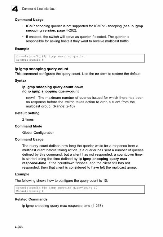
Command Line Interface4
Command Usage• IGMP snooping querier is not supported for IGMPv3 snooping (see ip igmp snooping version, page 4-262).
• If enabled, the switch will serve as querier if elected. The querier is responsible for asking hosts if they want to receive multicast traffic.
Example
ip igmp snooping query-countThis command configures the query count. Use the no form to restore the default.
Syntax
ip igmp snooping query-count countno ip igmp snooping query-count
count - The maximum number of queries issued for which there has been no response before the switch takes action to drop a client from the multicast group. (Range: 2-10)
Default Setting
2 times
Command Mode
Global Configuration
Command Usage
The query count defines how long the querier waits for a response from a multicast client before taking action. If a querier has sent a number of queries defined by this command, but a client has not responded, a countdown timer is started using the time defined by ip igmp snooping query-max- response-time. If the countdown finishes, and the client still has not responded, then that client is considered to have left the multicast group.
Example
The following shows how to configure the query count to 10:
Related Commands
ip igmp snooping query-max-response-time (4-267)
Console(config)#ip igmp snooping querierConsole(config)#
Console(config)#ip igmp snooping query-count 10Console(config)#
4-266
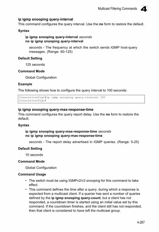
Multicast Filtering Commands 4
ip igmp snooping query-intervalThis command configures the query interval. Use the no form to restore the default.Syntax
ip igmp snooping query-interval secondsno ip igmp snooping query-interval
seconds - The frequency at which the switch sends IGMP host-query messages. (Range: 60-125)
Default Setting
125 seconds
Command Mode
Global Configuration
Example
The following shows how to configure the query interval to 100 seconds:
ip igmp snooping query-max-response-timeThis command configures the query report delay. Use the no form to restore the default.
Syntax
ip igmp snooping query-max-response-time secondsno ip igmp snooping query-max-response-time
seconds - The report delay advertised in IGMP queries. (Range: 5-25)
Default Setting
10 seconds
Command Mode
Global Configuration
Command Usage
• The switch must be using IGMPv2/v3 snooping for this command to take effect.
• This command defines the time after a query, during which a response is expected from a multicast client. If a querier has sent a number of queries defined by the ip igmp snooping query-count, but a client has not responded, a countdown timer is started using an initial value set by this command. If the countdown finishes, and the client still has not responded, then that client is considered to have left the multicast group.
Console(config)#ip igmp snooping query-interval 100Console(config)#
4-267
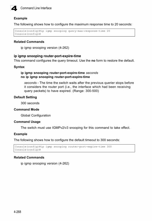
Command Line Interface4
ExampleThe following shows how to configure the maximum response time to 20 seconds:
Related Commands
ip igmp snooping version (4-262)
ip igmp snooping router-port-expire-timeThis command configures the query timeout. Use the no form to restore the default.
Syntax
ip igmp snooping router-port-expire-time secondsno ip igmp snooping router-port-expire-time
seconds - The time the switch waits after the previous querier stops before it considers the router port (i.e., the interface which had been receiving query packets) to have expired. (Range: 300-500)
Default Setting
300 seconds
Command Mode
Global Configuration
Command Usage
The switch must use IGMPv2/v3 snooping for this command to take effect.
Example
The following shows how to configure the default timeout to 300 seconds:
Related Commands
ip igmp snooping version (4-262)
Console(config)#ip igmp snooping query-max-response-time 20Console(config)#
Console(config)#ip igmp snooping router-port-expire-time 300Console(config)#
4-268
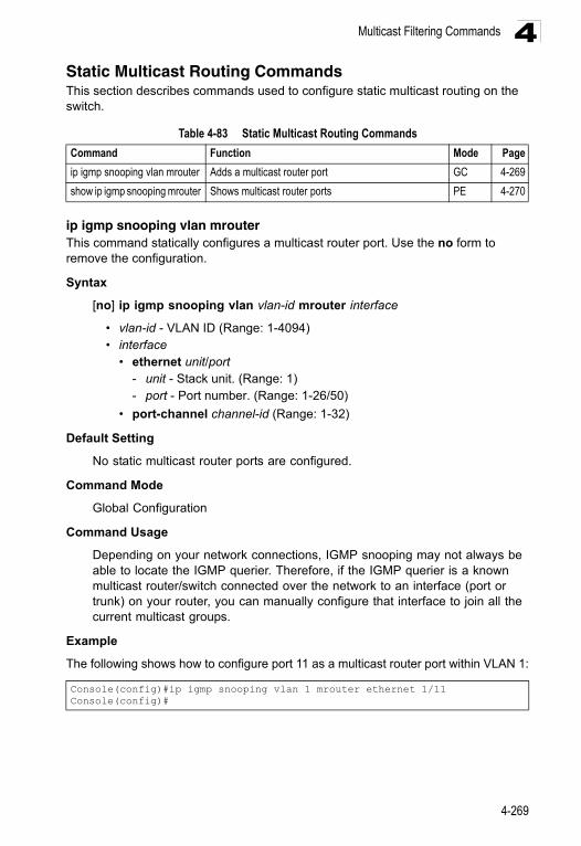
Multicast Filtering Commands 4
Static Multicast Routing CommandsThis section describes commands used to configure static multicast routing on the switch.ip igmp snooping vlan mrouterThis command statically configures a multicast router port. Use the no form to remove the configuration.
Syntax
[no] ip igmp snooping vlan vlan-id mrouter interface
• vlan-id - VLAN ID (Range: 1-4094) • interface
• ethernet unit/port - unit - Stack unit. (Range: 1) - port - Port number. (Range: 1-26/50)
• port-channel channel-id (Range: 1-32)
Default Setting
No static multicast router ports are configured.
Command Mode
Global Configuration
Command Usage
Depending on your network connections, IGMP snooping may not always be able to locate the IGMP querier. Therefore, if the IGMP querier is a known multicast router/switch connected over the network to an interface (port or trunk) on your router, you can manually configure that interface to join all the current multicast groups.
Example
The following shows how to configure port 11 as a multicast router port within VLAN 1:
Table 4-83 Static Multicast Routing Commands
Command Function Mode Page
ip igmp snooping vlan mrouter Adds a multicast router port GC 4-269
show ip igmp snooping mrouter Shows multicast router ports PE 4-270
Console(config)#ip igmp snooping vlan 1 mrouter ethernet 1/11Console(config)#
4-269
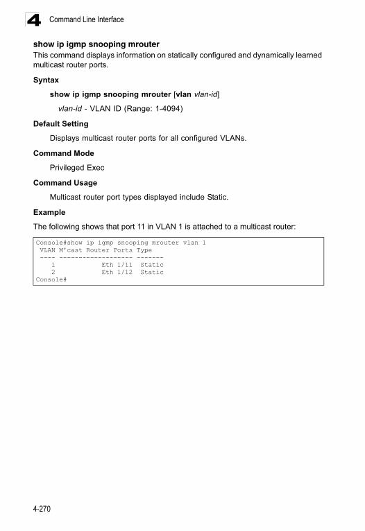
Command Line Interface4
show ip igmp snooping mrouter This command displays information on statically configured and dynamically learned multicast router ports.Syntax
show ip igmp snooping mrouter [vlan vlan-id]
vlan-id - VLAN ID (Range: 1-4094)
Default Setting
Displays multicast router ports for all configured VLANs.
Command Mode
Privileged Exec
Command Usage
Multicast router port types displayed include Static.
Example
The following shows that port 11 in VLAN 1 is attached to a multicast router:
Console#show ip igmp snooping mrouter vlan 1 VLAN M'cast Router Ports Type ---- ------------------- ------- 1 Eth 1/11 Static 2 Eth 1/12 StaticConsole#
4-270
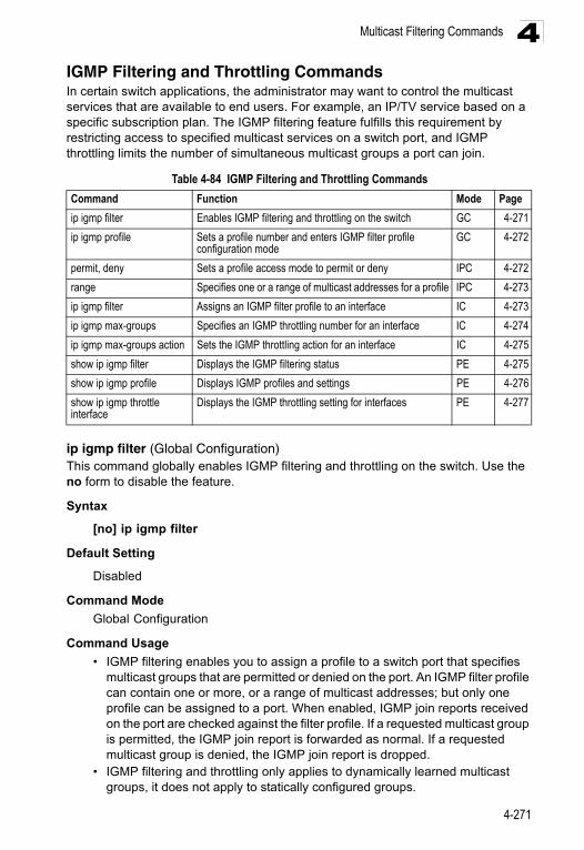
Multicast Filtering Commands 4
IGMP Filtering and Throttling CommandsIn certain switch applications, the administrator may want to control the multicast services that are available to end users. For example, an IP/TV service based on a specific subscription plan. The IGMP filtering feature fulfills this requirement by restricting access to specified multicast services on a switch port, and IGMP throttling limits the number of simultaneous multicast groups a port can join.ip igmp filter (Global Configuration)This command globally enables IGMP filtering and throttling on the switch. Use the no form to disable the feature.
Syntax
[no] ip igmp filter
Default Setting
Disabled
Command Mode
Global Configuration
Command Usage
• IGMP filtering enables you to assign a profile to a switch port that specifies multicast groups that are permitted or denied on the port. An IGMP filter profile can contain one or more, or a range of multicast addresses; but only one profile can be assigned to a port. When enabled, IGMP join reports received on the port are checked against the filter profile. If a requested multicast group is permitted, the IGMP join report is forwarded as normal. If a requested multicast group is denied, the IGMP join report is dropped.
• IGMP filtering and throttling only applies to dynamically learned multicast groups, it does not apply to statically configured groups.
Table 4-84 IGMP Filtering and Throttling Commands
Command Function Mode Page
ip igmp filter Enables IGMP filtering and throttling on the switch GC 4-271
ip igmp profile Sets a profile number and enters IGMP filter profile configuration mode
GC 4-272
permit, deny Sets a profile access mode to permit or deny IPC 4-272
range Specifies one or a range of multicast addresses for a profile IPC 4-273
ip igmp filter Assigns an IGMP filter profile to an interface IC 4-273
ip igmp max-groups Specifies an IGMP throttling number for an interface IC 4-274
ip igmp max-groups action Sets the IGMP throttling action for an interface IC 4-275
show ip igmp filter Displays the IGMP filtering status PE 4-275
show ip igmp profile Displays IGMP profiles and settings PE 4-276
show ip igmp throttle interface
Displays the IGMP throttling setting for interfaces PE 4-277
4-271
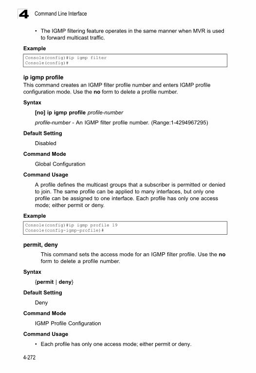
Command Line Interface4
• The IGMP filtering feature operates in the same manner when MVR is usedto forward multicast traffic.
Example
ip igmp profileThis command creates an IGMP filter profile number and enters IGMP profile configuration mode. Use the no form to delete a profile number.
Syntax
[no] ip igmp profile profile-number
profile-number - An IGMP filter profile number. (Range:1-4294967295)
Default Setting
Disabled
Command Mode
Global Configuration
Command Usage
A profile defines the multicast groups that a subscriber is permitted or denied to join. The same profile can be applied to many interfaces, but only one profile can be assigned to one interface. Each profile has only one access mode; either permit or deny.
Example
permit, deny
This command sets the access mode for an IGMP filter profile. Use the no form to delete a profile number.
Syntax
{permit | deny}
Default Setting
Deny
Command Mode
IGMP Profile Configuration
Command Usage
• Each profile has only one access mode; either permit or deny.
Console(config)#ip igmp filterConsole(config)#
Console(config)#ip igmp profile 19Console(config-igmp-profile)#
4-272
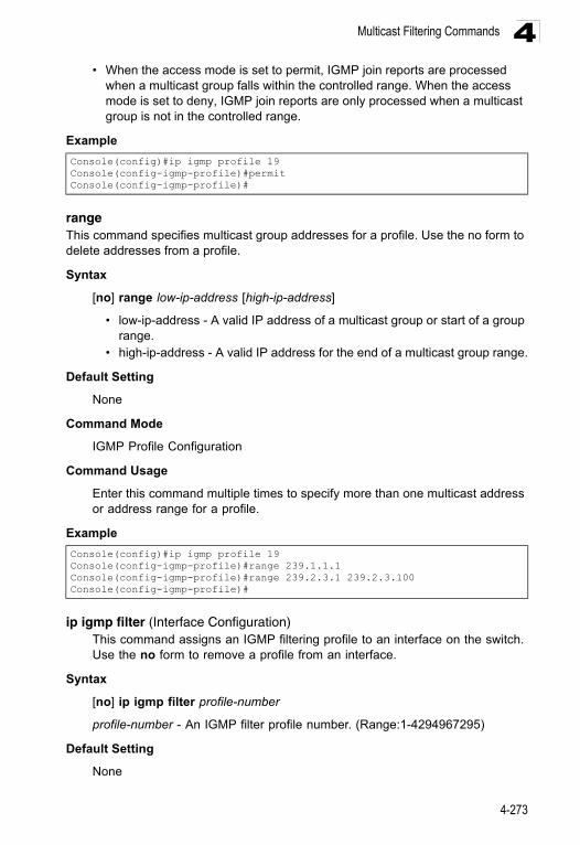
Multicast Filtering Commands 4
• When the access mode is set to permit, IGMP join reports are processedwhen a multicast group falls within the controlled range. When the access mode is set to deny, IGMP join reports are only processed when a multicast group is not in the controlled range.
Example
rangeThis command specifies multicast group addresses for a profile. Use the no form to delete addresses from a profile.
Syntax
[no] range low-ip-address [high-ip-address]
• low-ip-address - A valid IP address of a multicast group or start of a group range.
• high-ip-address - A valid IP address for the end of a multicast group range.
Default Setting
None
Command Mode
IGMP Profile Configuration
Command Usage
Enter this command multiple times to specify more than one multicast address or address range for a profile.
Example
ip igmp filter (Interface Configuration)This command assigns an IGMP filtering profile to an interface on the switch. Use the no form to remove a profile from an interface.
Syntax
[no] ip igmp filter profile-number
profile-number - An IGMP filter profile number. (Range:1-4294967295)
Default Setting
None
Console(config)#ip igmp profile 19Console(config-igmp-profile)#permitConsole(config-igmp-profile)#
Console(config)#ip igmp profile 19Console(config-igmp-profile)#range 239.1.1.1Console(config-igmp-profile)#range 239.2.3.1 239.2.3.100Console(config-igmp-profile)#
4-273
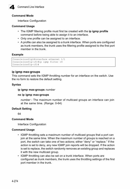
Command Line Interface4
Command ModeInterface Configuration
Command Usage
• The IGMP filtering profile must first be created with the ip igmp profile command before being able to assign it to an interface.
• Only one profile can be assigned to an interface.• A profile can also be assigned to a trunk interface. When ports are configured
as trunk members, the trunk uses the filtering profile assigned to the first port member in the trunk.
Example
ip igmp max-groupsThis command sets the IGMP throttling number for an interface on the switch. Use the no form to restore the default setting.
Syntax
ip igmp max-groups number
no ip igmp max-groups
number - The maximum number of multicast groups an interface can join at the same time. (Range: 0-64)
Default Setting
64
Command Mode
Interface Configuration
Command Usage
• IGMP throttling sets a maximum number of multicast groups that a port can join at the same time. When the maximum number of groups is reached on a port, the switch can take one of two actions; either “deny” or “replace.” If the action is set to deny, any new IGMP join reports will be dropped. If the action is set to replace, the switch randomly removes an existing group and replaces it with the new multicast group.
• IGMP throttling can also be set on a trunk interface. When ports are configured as trunk members, the trunk uses the throttling settings of the first port member in the trunk.
Console(config)#interface ethernet 1/1Console(config-if)#ip igmp filter 19Console(config-if)#
4-274
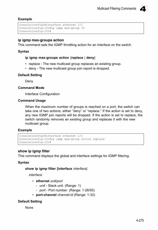
Multicast Filtering Commands 4
Exampleip igmp max-groups actionThis command sets the IGMP throttling action for an interface on the switch.
Syntax
ip igmp max-groups action {replace | deny}
• replace - The new multicast group replaces an existing group.• deny - The new multicast group join report is dropped.
Default Setting
Deny
Command Mode
Interface Configuration
Command Usage
When the maximum number of groups is reached on a port, the switch can take one of two actions; either “deny” or “replace.” If the action is set to deny, any new IGMP join reports will be dropped. If the action is set to replace, the switch randomly removes an existing group and replaces it with the new multicast group.
Example
show ip igmp filterThis command displays the global and interface settings for IGMP filtering.
Syntax
show ip igmp filter [interface interface]
interface
• ethernet unit/port- unit - Stack unit. (Range: 1)- port - Port number. (Range: 1-26/50)
• port-channel channel-id (Range: 1-32)
Default Setting
None
Console(config)#interface ethernet 1/1Console(config-if)#ip igmp max-group 10Console(config-if)#
Console(config)#interface ethernet 1/1Console(config-if)#ip igmp max-group action replaceConsole(config-if)#
4-275
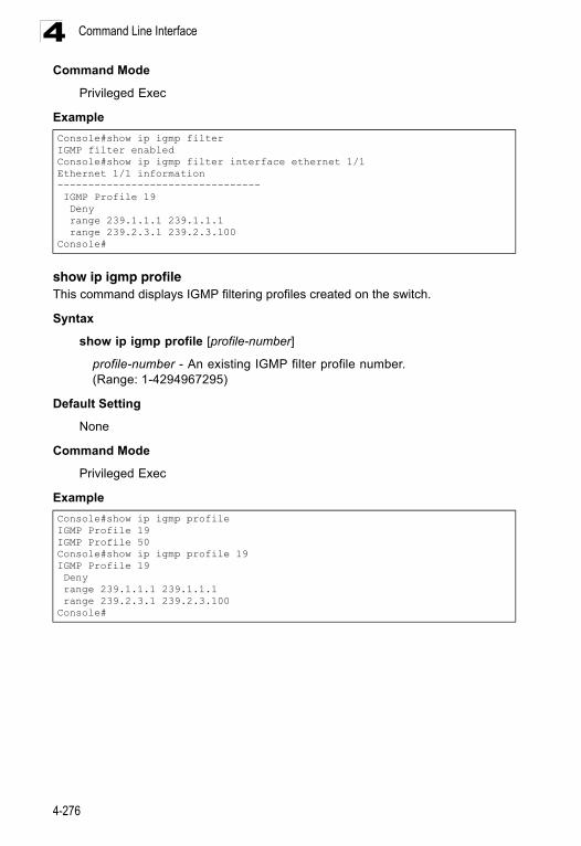
Command Line Interface4
Command ModePrivileged Exec
Example
show ip igmp profileThis command displays IGMP filtering profiles created on the switch.
Syntax
show ip igmp profile [profile-number]
profile-number - An existing IGMP filter profile number. (Range: 1-4294967295)
Default Setting
None
Command Mode
Privileged Exec
Example
Console#show ip igmp filterIGMP filter enabledConsole#show ip igmp filter interface ethernet 1/1Ethernet 1/1 information--------------------------------- IGMP Profile 19 Deny range 239.1.1.1 239.1.1.1 range 239.2.3.1 239.2.3.100Console#
Console#show ip igmp profileIGMP Profile 19IGMP Profile 50Console#show ip igmp profile 19IGMP Profile 19 Deny range 239.1.1.1 239.1.1.1 range 239.2.3.1 239.2.3.100Console#
4-276
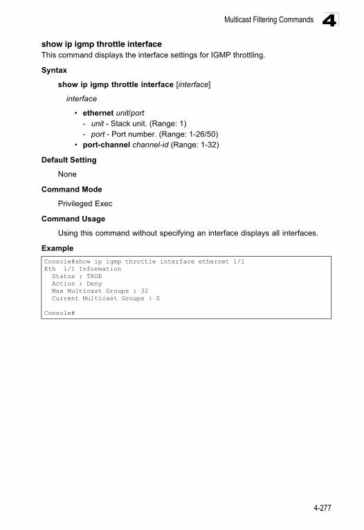
Multicast Filtering Commands 4
show ip igmp throttle interfaceThis command displays the interface settings for IGMP throttling.Syntax
show ip igmp throttle interface [interface]
interface
• ethernet unit/port- unit - Stack unit. (Range: 1) - port - Port number. (Range: 1-26/50)
• port-channel channel-id (Range: 1-32)
Default Setting
None
Command Mode
Privileged Exec
Command Usage
Using this command without specifying an interface displays all interfaces.
Example
Console#show ip igmp throttle interface ethernet 1/1Eth 1/1 Information Status : TRUE Action : Deny Max Multicast Groups : 32 Current Multicast Groups : 0
Console#
4-277
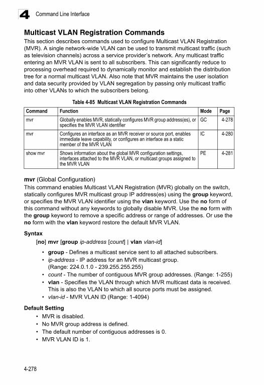
Command Line Interface4
Multicast VLAN Registration CommandsThis section describes commands used to configure Multicast VLAN Registration (MVR). A single network-wide VLAN can be used to transmit multicast traffic (such as television channels) across a service provider’s network. Any multicast traffic entering an MVR VLAN is sent to all subscribers. This can significantly reduce to processing overhead required to dynamically monitor and establish the distribution tree for a normal multicast VLAN. Also note that MVR maintains the user isolation and data security provided by VLAN segregation by passing only multicast traffic into other VLANs to which the subscribers belong.mvr (Global Configuration)This command enables Multicast VLAN Registration (MVR) globally on the switch, statically configures MVR multicast group IP address(es) using the group keyword, or specifies the MVR VLAN identifier using the vlan keyword. Use the no form of this command without any keywords to globally disable MVR. Use the no form with the group keyword to remove a specific address or range of addresses. Or use the no form with the vlan keyword restore the default MVR VLAN.
Syntax
[no] mvr [group ip-address [count] | vlan vlan-id]
• group - Defines a multicast service sent to all attached subscribers.• ip-address - IP address for an MVR multicast group.
(Range: 224.0.1.0 - 239.255.255.255) • count - The number of contiguous MVR group addresses. (Range: 1-255) • vlan - Specifies the VLAN through which MVR multicast data is received.
This is also the VLAN to which all source ports must be assigned. • vlan-id - MVR VLAN ID (Range: 1-4094)
Default Setting
• MVR is disabled.• No MVR group address is defined.• The default number of contiguous addresses is 0.• MVR VLAN ID is 1.
Table 4-85 Multicast VLAN Registration Commands
Command Function Mode Page
mvr Globally enables MVR, statically configures MVR group address(es), or specifies the MVR VLAN identifier
GC 4-278
mvr Configures an interface as an MVR receiver or source port, enables immediate leave capability, or configures an interface as a static member of the MVR VLAN
IC 4-280
show mvr Shows information about the global MVR configuration settings, interfaces attached to the MVR VLAN, or multicast groups assigned to the MVR VLAN
PE 4-281
4-278
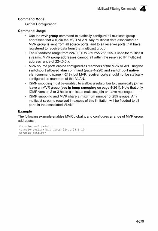
Multicast Filtering Commands 4
Command ModeGlobal Configuration
Command Usage
• Use the mvr group command to statically configure all multicast group addresses that will join the MVR VLAN. Any multicast data associated an MVR group is sent from all source ports, and to all receiver ports that have registered to receive data from that multicast group.
• The IP address range from 224.0.0.0 to 239.255.255.255 is used for multicast streams. MVR group addresses cannot fall within the reserved IP multicast address range of 224.0.0.x.
• MVR source ports can be configured as members of the MVR VLAN using the switchport allowed vlan command (page 4-220) and switchport native vlan command (page 4-219), but MVR receiver ports should not be statically configured as members of this VLAN.
• IGMP snooping must be enabled to a allow a subscriber to dynamically join or leave an MVR group (see ip igmp snooping on page 4-261). Note that only IGMP version 2 or 3 hosts can issue multicast join or leave messages.
• IGMP snooping and MVR share a maximum number of 255 groups. Any multicast streams received in excess of this limitation will be flooded to all ports in the associated VLAN.
Example
The following example enables MVR globally, and configures a range of MVR group addresses:
Console(config)#mvrConsole(config)#mvr group 228.1.23.1 10Console(config)#
4-279
Command Line Interface4
mvr (Interface Configuration)This command configures an interface as an MVR receiver or source port using the type keyword, enables immediate leave capability using the immediate keyword, or configures an interface as a static member of the MVR VLAN using the group keyword. Use the no form to restore the default settings.Syntax
[no] mvr {type {receiver | source} | immediate | group ip-address}
• receiver - Configures the interface as a subscriber port that can receive multicast data.
• source - Configure the interface as an uplink port that can send and receive multicast data for the configured multicast groups.
• immediate - Configures the switch to immediately remove an interface from a multicast stream as soon as it receives a leave message for that group.
• group - Defines a multicast service sent to the selected port. • ip-address - Statically configures an interface to receive multicast traffic
from the IP address specified for an MVR multicast group. (Range: 224.0.1.0 - 239.255.255.255)
Default Setting
• The port type is not defined.• Immediate leave is disabled.• No receiver port is a member of any configured multicast group.
Command Mode
Interface Configuration (Ethernet, Port Channel)
Command Usage
• A port which is not configured as an MVR receiver or source port can use IGMP snooping to join or leave multicast groups using the standard rules for multicast filtering.
• Receiver ports can belong to different VLANs, but should not be configured as a member of the MVR VLAN. IGMP snooping can be used to allow a receiver port to dynamically join or leave multicast groups within the MVR VLAN. Multicast groups can also be statically assigned to a receiver port using the group keyword. However, if a receiver port is statically configured as a member of an MVR VLAN, its status will be inactive. Also, note that VLAN membership for MVR receiver ports cannot be set to trunk mode (see the switchport mode command on page 4-217).
• One or more interfaces may be configured as MVR source ports. A source port is able to both receive and send data for multicast groups which it has joined through IGMP snooping or which have been statically assigned using the group keyword.
• The IP address range from 224.0.0.0 to 239.255.255.255 is used for multicast streams. MVR group addresses cannot fall within the reserved IP multicast address range of 224.0.0.x.
4-280
Multicast Filtering Commands 4
• Immediate leave applies only to receiver ports. When enabled, the receiverport is immediately removed from the multicast group identified in the leave message. When immediate leave is disabled, the switch follows the standard rules by sending a group-specific query to the receiver port and waiting for a response to determine if there are any remaining subscribers for that multicast group before removing the port from the group list.
• Using immediate leave can speed up leave latency, but should only be enabled on a port attached to one multicast subscriber to avoid disrupting services to other group members attached to the same interface.
• Immediate leave does not apply to multicast groups which have been statically assigned to a port.
• IGMP snooping must be enabled to a allow a subscriber to dynamically join or leave an MVR group (see ip igmp snooping on page 4-261). Note that only IGMP version 2 or 3 hosts can issue multicast join or leave messages.
Example
The following configures one source port and several receiver ports on the switch, enables immediate leave on one of the receiver ports, and statically assigns a multicast group to another receiver port:
show mvr This command shows information about the global MVR configuration settings when entered without any keywords, the interfaces attached to the MVR VLAN using the interface keyword, or the multicast groups assigned to the MVR VLAN using the members keyword.
Syntax
show mvr [interface [interface] | members [ip-address]]
• interface • ethernet unit/port
- unit - Stack unit. (Range: 1) - port - Port number. (Range: 1-26/50)
• port-channel channel-id (Range: 1-32) • ip-address - IP address for an MVR multicast group.
(Range: 224.0.1.0 - 239.255.255.255)
Console(config)#interface ethernet 1/5Console(config-if)#mvr type sourceConsole(config-if)#exitConsole(config)#interface ethernet 1/6Console(config-if)#mvr type receiverConsole(config-if)#mvr immediateConsole(config-if)#exitConsole(config)#interface ethernet 1/7Console(config-if)#mvr type receiverConsole(config-if)#mvr group 225.0.0.5Console(config-if)#
4-281
Command Line Interface4
Default SettingDisplays global configuration settings for MVR when no keywords are used.
Command Mode
Privileged Exec
Command Usage
Enter this command without any keywords to display the global settings for MVR. Use the interface keyword to display information about interfaces attached to the MVR VLAN. Or use the members keyword to display information about multicast groups assigned to the MVR VLAN.
Example
The following shows the global MVR settings:
The following displays information about the interfaces attached to the MVR VLAN:
Console#show mvrMVR Status:enableMVR running status:TRUEMVR multicast vlan:1MVR Max Multicast Groups:255MVR Current multicast groups:10Console#
Table 4-86 show mvr - display description
Field Description
MVR Status Shows if MVR is globally enabled on the switch.
MVR running status Indicates whether or not all necessary conditions in the MVR environment are satisfied.
MVR multicast vlan Shows the VLAN used to transport all MVR multicast traffic.
MVR Max Multicast Groups Shows the maximum number of multicast groups which can assigned to the MVR VLAN.
MVR Current multicast groups Shows the number of multicast groups currently assigned to the MVR VLAN.
Console#show mvr interfacePort Type Status Immediate Leave------- -------- ------------- ---------------eth1/1 SOURCE ACTIVE/UP Disableeth1/2 RECEIVER ACTIVE/UP Disableeth1/5 RECEIVER INACTIVE/DOWN Disableeth1/6 RECEIVER INACTIVE/DOWN Disableeth1/7 RECEIVER INACTIVE/DOWN DisableConsole#
Table 4-87 show mvr interface - display description
Field Description
Port Shows interfaces attached to the MVR.
Type Shows the MVR port type.
4-282
Multicast Filtering Commands 4
The following shows information about the interfaces associated with multicast groups assigned to the MVR VLAN:
Status Shows the MVR status and interface status. MVR status for source ports is “ACTIVE” if MVR is globally enabled on the switch. MVR status for receiver ports is “ACTIVE” only if there are subscribers receiving multicast traffic from one of the MVR groups, or a multicast group has been statically assigned to an interface.
Immediate Leave Shows if immediate leave is enabled or disabled.
Console#show mvr membersMVR Group IP Status Members---------------- -------- -------225.0.0.1 ACTIVE eth1/1(d), eth1/2(s)225.0.0.2 INACTIVE None225.0.0.3 INACTIVE None225.0.0.4 INACTIVE None225.0.0.5 INACTIVE None225.0.0.6 INACTIVE None225.0.0.7 INACTIVE None225.0.0.8 INACTIVE None225.0.0.9 INACTIVE None225.0.0.10 INACTIVE NoneConsole#
Table 4-88 show mvr members - display description
Field Description
MVR Group IP Multicast groups assigned to the MVR VLAN.
Status Shows whether or not the there are active subscribers for this multicast group. Note that this field will also display “INACTIVE” if MVR is globally disabled.
Members Shows the interfaces with subscribers for multicast services provided through the MVR VLAN. Also shows if an interface has dynamically joined a multicast group (d), or if a multicast group has been statically bound to the interface (s).
Table 4-87 show mvr interface - display description (Continued)
Field Description
4-283
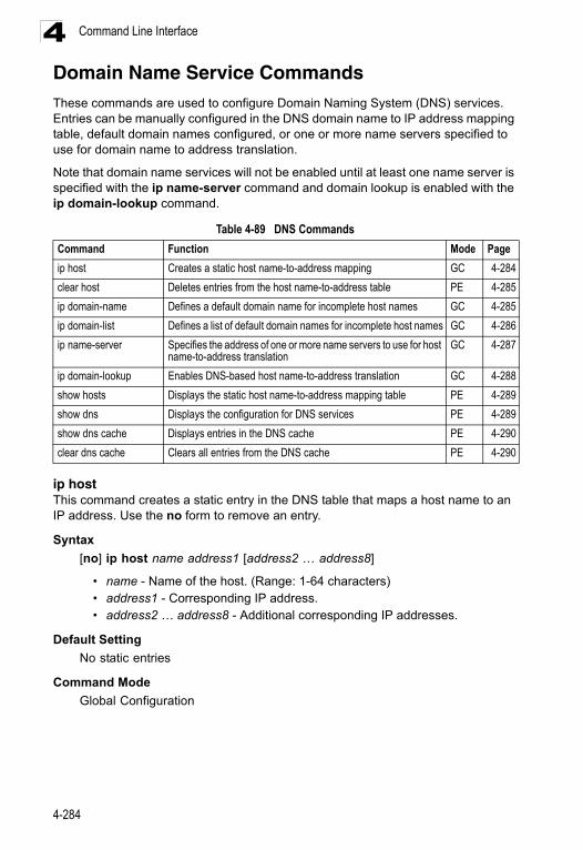
Command Line Interface4
Domain Name Service CommandsThese commands are used to configure Domain Naming System (DNS) services. Entries can be manually configured in the DNS domain name to IP address mapping table, default domain names configured, or one or more name servers specified to use for domain name to address translation.Note that domain name services will not be enabled until at least one name server is specified with the ip name-server command and domain lookup is enabled with the ip domain-lookup command.
ip hostThis command creates a static entry in the DNS table that maps a host name to an IP address. Use the no form to remove an entry.
Syntax
[no] ip host name address1 [address2 … address8]
• name - Name of the host. (Range: 1-64 characters)• address1 - Corresponding IP address.• address2 … address8 - Additional corresponding IP addresses.
Default Setting
No static entries
Command Mode
Global Configuration
Table 4-89 DNS Commands
Command Function Mode Page
ip host Creates a static host name-to-address mapping GC 4-284
clear host Deletes entries from the host name-to-address table PE 4-285
ip domain-name Defines a default domain name for incomplete host names GC 4-285
ip domain-list Defines a list of default domain names for incomplete host names GC 4-286
ip name-server Specifies the address of one or more name servers to use for host name-to-address translation
GC 4-287
ip domain-lookup Enables DNS-based host name-to-address translation GC 4-288
show hosts Displays the static host name-to-address mapping table PE 4-289
show dns Displays the configuration for DNS services PE 4-289
show dns cache Displays entries in the DNS cache PE 4-290
clear dns cache Clears all entries from the DNS cache PE 4-290
4-284
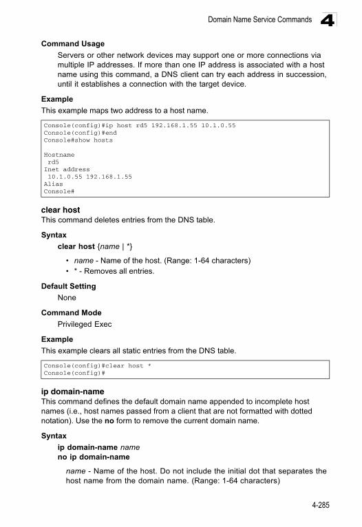
Domain Name Service Commands 4
Command UsageServers or other network devices may support one or more connections via multiple IP addresses. If more than one IP address is associated with a host name using this command, a DNS client can try each address in succession, until it establishes a connection with the target device.
Example
This example maps two address to a host name.
clear hostThis command deletes entries from the DNS table.
Syntax
clear host {name | *}
• name - Name of the host. (Range: 1-64 characters)• * - Removes all entries.
Default Setting
None
Command Mode
Privileged Exec
Example
This example clears all static entries from the DNS table.
ip domain-nameThis command defines the default domain name appended to incomplete host names (i.e., host names passed from a client that are not formatted with dotted notation). Use the no form to remove the current domain name.
Syntax
ip domain-name nameno ip domain-name
name - Name of the host. Do not include the initial dot that separates the host name from the domain name. (Range: 1-64 characters)
Console(config)#ip host rd5 192.168.1.55 10.1.0.55Console(config)#endConsole#show hosts
Hostname rd5Inet address 10.1.0.55 192.168.1.55AliasConsole#
Console(config)#clear host *Console(config)#
4-285
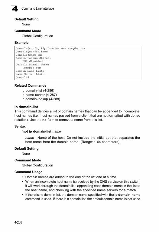
Command Line Interface4
Default SettingNone
Command Mode
Global Configuration
Example
Related Commands
ip domain-list (4-286)ip name-server (4-287)ip domain-lookup (4-288)
ip domain-listThis command defines a list of domain names that can be appended to incomplete host names (i.e., host names passed from a client that are not formatted with dotted notation). Use the no form to remove a name from this list.
Syntax
[no] ip domain-list name
name - Name of the host. Do not include the initial dot that separates the host name from the domain name. (Range: 1-64 characters)
Default Setting
None
Command Mode
Global Configuration
Command Usage
• Domain names are added to the end of the list one at a time. • When an incomplete host name is received by the DNS service on this switch,
it will work through the domain list, appending each domain name in the list to the host name, and checking with the specified name servers for a match.
• If there is no domain list, the domain name specified with the ip domain-name command is used. If there is a domain list, the default domain name is not used.
Console(config)#ip domain-name sample.comConsole(config)#endConsole#show dnsDomain Lookup Status: DNS disabledDefault Domain Name: .sample.comDomain Name List:Name Server List:Console#
4-286
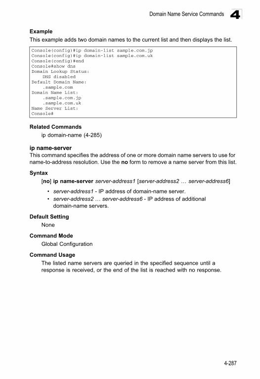
Domain Name Service Commands 4
ExampleThis example adds two domain names to the current list and then displays the list.
Related Commands
ip domain-name (4-285)
ip name-serverThis command specifies the address of one or more domain name servers to use for name-to-address resolution. Use the no form to remove a name server from this list.
Syntax
[no] ip name-server server-address1 [server-address2 … server-address6]
• server-address1 - IP address of domain-name server.• server-address2 … server-address6 - IP address of additional
domain-name servers.
Default Setting
None
Command Mode
Global Configuration
Command Usage
The listed name servers are queried in the specified sequence until a response is received, or the end of the list is reached with no response.
Console(config)#ip domain-list sample.com.jpConsole(config)#ip domain-list sample.com.ukConsole(config)#endConsole#show dnsDomain Lookup Status: DNS disabledDefault Domain Name: .sample.comDomain Name List: .sample.com.jp .sample.com.ukName Server List:Console#
4-287
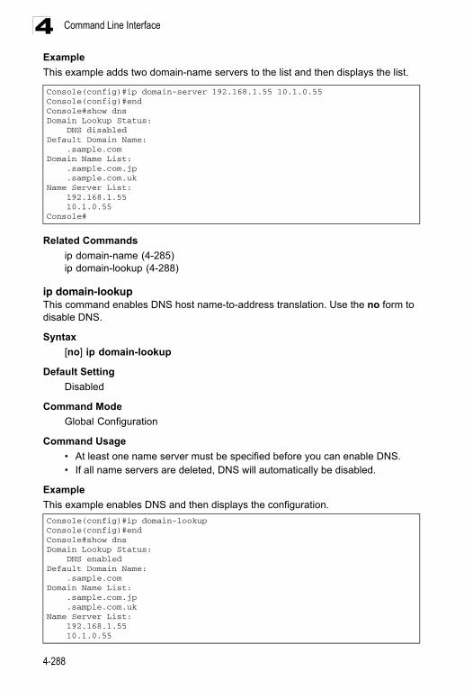
Command Line Interface4
ExampleThis example adds two domain-name servers to the list and then displays the list.
Related Commands
ip domain-name (4-285)ip domain-lookup (4-288)
ip domain-lookupThis command enables DNS host name-to-address translation. Use the no form to disable DNS.
Syntax
[no] ip domain-lookup
Default Setting
Disabled
Command Mode
Global Configuration
Command Usage
• At least one name server must be specified before you can enable DNS. • If all name servers are deleted, DNS will automatically be disabled.
Example
This example enables DNS and then displays the configuration.
Console(config)#ip domain-server 192.168.1.55 10.1.0.55Console(config)#endConsole#show dnsDomain Lookup Status: DNS disabledDefault Domain Name: .sample.comDomain Name List: .sample.com.jp .sample.com.ukName Server List: 192.168.1.55 10.1.0.55Console#
Console(config)#ip domain-lookupConsole(config)#endConsole#show dnsDomain Lookup Status: DNS enabledDefault Domain Name: .sample.comDomain Name List: .sample.com.jp .sample.com.ukName Server List: 192.168.1.55 10.1.0.55
4-288
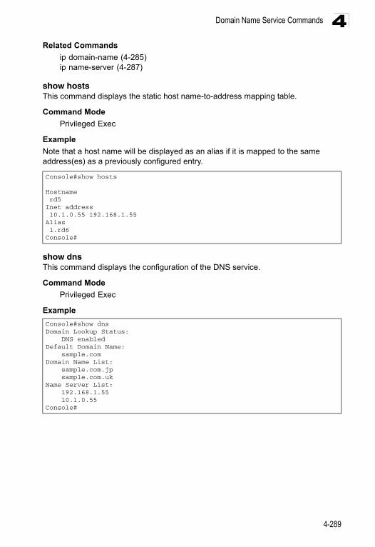
Domain Name Service Commands 4
Related Commandsip domain-name (4-285)ip name-server (4-287)
show hostsThis command displays the static host name-to-address mapping table.
Command Mode
Privileged Exec
Example
Note that a host name will be displayed as an alias if it is mapped to the same address(es) as a previously configured entry.
show dnsThis command displays the configuration of the DNS service.
Command Mode
Privileged Exec
Example
Console#show hosts
Hostname rd5Inet address 10.1.0.55 192.168.1.55Alias 1.rd6Console#
Console#show dnsDomain Lookup Status: DNS enabledDefault Domain Name: sample.comDomain Name List: sample.com.jp sample.com.ukName Server List: 192.168.1.55 10.1.0.55Console#
4-289
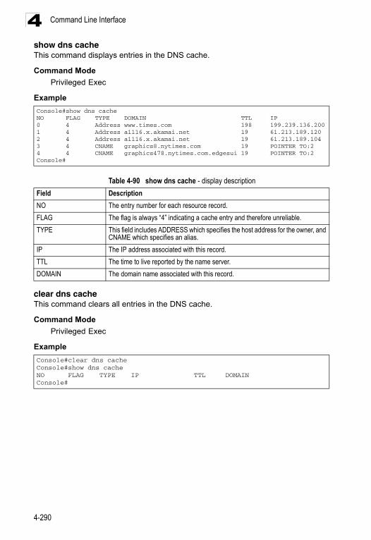
Command Line Interface4
show dns cacheThis command displays entries in the DNS cache.Command Mode
Privileged Exec
Example
clear dns cacheThis command clears all entries in the DNS cache.
Command Mode
Privileged Exec
Example
Console#show dns cacheNO FLAG TYPE DOMAIN TTL IP0 4 Address www.times.com 198 199.239.136.2001 4 Address a1116.x.akamai.net 19 61.213.189.1202 4 Address a1116.x.akamai.net 19 61.213.189.1043 4 CNAME graphics8.nytimes.com 19 POINTER TO:24 4 CNAME graphics478.nytimes.com.edgesui 19 POINTER TO:2Console#
Table 4-90 show dns cache - display description
Field Description
NO The entry number for each resource record.
FLAG The flag is always “4” indicating a cache entry and therefore unreliable.
TYPE This field includes ADDRESS which specifies the host address for the owner, and CNAME which specifies an alias.
IP The IP address associated with this record.
TTL The time to live reported by the name server.
DOMAIN The domain name associated with this record.
Console#clear dns cacheConsole#show dns cacheNO FLAG TYPE IP TTL DOMAINConsole#
4-290
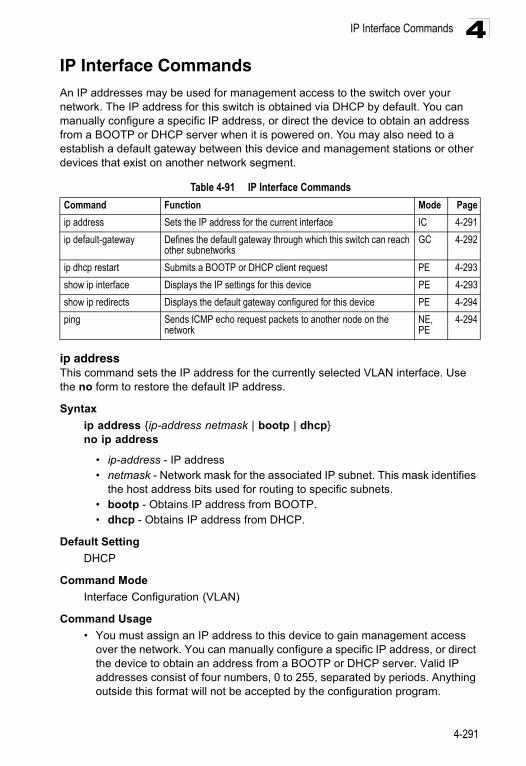
IP Interface Commands 4
IP Interface CommandsAn IP addresses may be used for management access to the switch over your network. The IP address for this switch is obtained via DHCP by default. You can manually configure a specific IP address, or direct the device to obtain an address from a BOOTP or DHCP server when it is powered on. You may also need to a establish a default gateway between this device and management stations or other devices that exist on another network segment.ip address This command sets the IP address for the currently selected VLAN interface. Use the no form to restore the default IP address.
Syntax
ip address {ip-address netmask | bootp | dhcp}no ip address
• ip-address - IP address • netmask - Network mask for the associated IP subnet. This mask identifies
the host address bits used for routing to specific subnets. • bootp - Obtains IP address from BOOTP. • dhcp - Obtains IP address from DHCP.
Default Setting
DHCP
Command Mode
Interface Configuration (VLAN)
Command Usage
• You must assign an IP address to this device to gain management access over the network. You can manually configure a specific IP address, or direct the device to obtain an address from a BOOTP or DHCP server. Valid IP addresses consist of four numbers, 0 to 255, separated by periods. Anything outside this format will not be accepted by the configuration program.
Table 4-91 IP Interface Commands
Command Function Mode Page
ip address Sets the IP address for the current interface IC 4-291
ip default-gateway Defines the default gateway through which this switch can reach other subnetworks
GC 4-292
ip dhcp restart Submits a BOOTP or DHCP client request PE 4-293
show ip interface Displays the IP settings for this device PE 4-293
show ip redirects Displays the default gateway configured for this device PE 4-294
ping Sends ICMP echo request packets to another node on the network
NE, PE
4-294
4-291
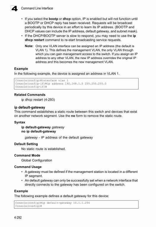
Command Line Interface4
• If you select the bootp or dhcp option, IP is enabled but will not function untila BOOTP or DHCP reply has been received. Requests will be broadcast periodically by this device in an effort to learn its IP address. (BOOTP and DHCP values can include the IP address, default gateway, and subnet mask).
• If the DHCP/BOOTP server is slow to respond, you may need to use the ip dhcp restart command to re-start broadcasting service requests.
Note: Only one VLAN interface can be assigned an IP address (the default is VLAN 1). This defines the management VLAN, the only VLAN through which you can gain management access to the switch. If you assign an IP address to any other VLAN, the new IP address overrides the original IP address and this becomes the new management VLAN.
Example
In the following example, the device is assigned an address in VLAN 1.
Related Commands
ip dhcp restart (4-293)
ip default-gatewayThis command establishes a static route between this switch and devices that exist on another network segment. Use the no form to remove the static route.
Syntax
ip default-gateway gatewayno ip default-gateway
gateway - IP address of the default gateway
Default Setting
No static route is established.
Command Mode
Global Configuration
Command Usage
• A gateway must be defined if the management station is located in a different IP segment.
• An default gateway can only be successfully set when a network interface that directly connects to the gateway has been configured on the switch.
Example
The following example defines a default gateway for this device:
Console(config)#interface vlan 1Console(config-if)#ip address 192.168.1.5 255.255.255.0Console(config-if)#
Console(config)#ip default-gateway 10.1.1.254Console(config)#
4-292
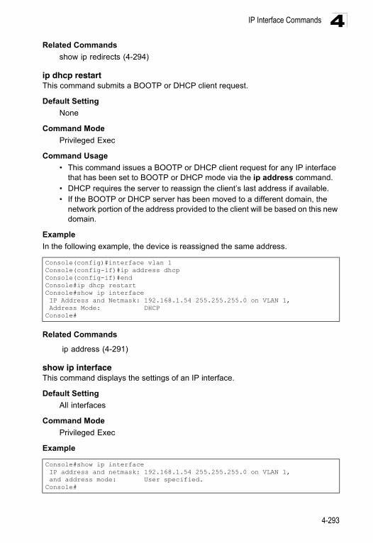
IP Interface Commands 4
Related Commandsshow ip redirects (4-294)
ip dhcp restart This command submits a BOOTP or DHCP client request.
Default Setting
None
Command Mode
Privileged Exec
Command Usage
• This command issues a BOOTP or DHCP client request for any IP interface that has been set to BOOTP or DHCP mode via the ip address command.
• DHCP requires the server to reassign the client’s last address if available. • If the BOOTP or DHCP server has been moved to a different domain, the
network portion of the address provided to the client will be based on this new domain.
Example
In the following example, the device is reassigned the same address.
Related Commands
ip address (4-291)
show ip interfaceThis command displays the settings of an IP interface.
Default Setting
All interfaces
Command Mode
Privileged Exec
Example
Console(config)#interface vlan 1Console(config-if)#ip address dhcpConsole(config-if)#endConsole#ip dhcp restart Console#show ip interface IP Address and Netmask: 192.168.1.54 255.255.255.0 on VLAN 1, Address Mode: DHCPConsole#
Console#show ip interface IP address and netmask: 192.168.1.54 255.255.255.0 on VLAN 1, and address mode: User specified.Console#
4-293
Command Line Interface4
Related Commandsshow ip redirects (4-294)
show ip redirectsThis command shows the default gateway configured for this device.
Default Setting
None
Command Mode
Privileged Exec
Example
Related Commands
ip default-gateway (4-292)
pingThis command sends ICMP echo request packets to another node on the network.
Syntax
ping host [size size] [count count]
• host - IP address or IP alias of the host. • size - Number of bytes in a packet. (Range: 32-512, default: 32)
The actual packet size will be eight bytes larger than the size specified because the switch adds header information.
• count - Number of packets to send. (Range: 1-16, default: 5)
Default Setting
This command has no default for the host.
Command Mode
Normal Exec, Privileged Exec
Command Usage
• Use the ping command to see if another site on the network can be reached. • Following are some results of the ping command:
- Normal response - The normal response occurs in one to ten seconds, depending on network traffic.
- Destination does not respond - If the host does not respond, a “timeout” appears in ten seconds.
- Destination unreachable - The gateway for this destination indicates that the destination is unreachable.
- Network or host unreachable - The gateway found no corresponding entry in the route table.
Console#show ip redirectsIP default gateway 10.1.0.254Console#
4-294

IP Interface Commands 4
• Press <Esc> to stop pinging.Example
Related Commands
interface (4-155)
Console#ping 10.1.0.9Type ESC to abort.PING to 10.1.0.9, by 5 32-byte payload ICMP packets, timeout is 5 secondsresponse time: 10 msresponse time: 10 msresponse time: 10 msresponse time: 10 msresponse time: 10 msPing statistics for 10.1.0.9: 5 packets transmitted, 5 packets received (100%), 0 packets lost (0%)Approximate round trip times: Minimum = 10 ms, Maximum = 20 ms, Average = 10 msConsole#
4-295

Command Line Interface4
4-296
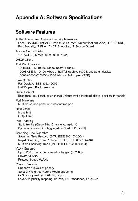
Appendix A: Software Specifications
Software FeaturesAuthentication and General Security Measures
Local, RADIUS, TACACS, Port (802.1X, MAC Authentication), AAA, HTTPS, SSH, Port Security, IP Filter, DHCP Snooping, IP Source Guard
Access Control Lists128 ACLS (96 MAC rules, 96 IP rules)
DHCP Client
Port Configuration100BASE-TX: 10/100 Mbps, half/full duplex1000BASE-T: 10/100 Mbps at half/full duplex, 1000 Mbps at full duplex1000BASE-SX/LX/ZX - 1000 Mbps at full duplex (SFP)
Flow ControlFull Duplex: IEEE 802.3-2002Half Duplex: Back pressure
Storm Control Broadcast, multicast, or unknown unicast traffic throttled above a critical threshold
Port MirroringMultiple source ports, one destination port
Rate LimitsInput limitOutput limit
Port TrunkingStatic trunks (Cisco EtherChannel compliant)Dynamic trunks (Link Aggregation Control Protocol)
Spanning Tree AlgorithmSpanning Tree Protocol (STP, IEEE 802.1D-2004) Rapid Spanning Tree Protocol (RSTP, IEEE 802.1D-2004) Multiple Spanning Trees (MSTP, IEEE 802.1D-2004)
VLAN SupportUp to 256 groups; port-based or tagged (802.1Q),Private VLANsProtocol-based VLANs
Class of ServiceSupports 4 levels of priorityStrict or Weighted Round Robin queueingCoS configured by VLAN tag or portLayer 3/4 priority mapping: IP Port, IP Precedence, IP DSCP
A-1
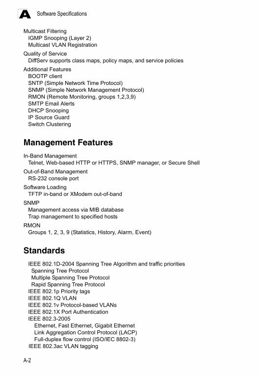
Software SpecificationsA
Multicast FilteringIGMP Snooping (Layer 2)Multicast VLAN Registration
Quality of ServiceDiffServ supports class maps, policy maps, and service policies
Additional FeaturesBOOTP clientSNTP (Simple Network Time Protocol)SNMP (Simple Network Management Protocol)RMON (Remote Monitoring, groups 1,2,3,9)SMTP Email Alerts DHCP SnoopingIP Source GuardSwitch Clustering
Management FeaturesIn-Band Management
Telnet, Web-based HTTP or HTTPS, SNMP manager, or Secure Shell
Out-of-Band ManagementRS-232 console port
Software LoadingTFTP in-band or XModem out-of-band
SNMPManagement access via MIB databaseTrap management to specified hosts
RMONGroups 1, 2, 3, 9 (Statistics, History, Alarm, Event)
StandardsIEEE 802.1D-2004 Spanning Tree Algorithm and traffic priorities Spanning Tree Protocol Multiple Spanning Tree Protocol Rapid Spanning Tree ProtocolIEEE 802.1p Priority tagsIEEE 802.1Q VLANIEEE 802.1v Protocol-based VLANsIEEE 802.1X Port AuthenticationIEEE 802.3-2005
Ethernet, Fast Ethernet, Gigabit EthernetLink Aggregation Control Protocol (LACP)Full-duplex flow control (ISO/IEC 8802-3)
IEEE 802.3ac VLAN tagging
A-2
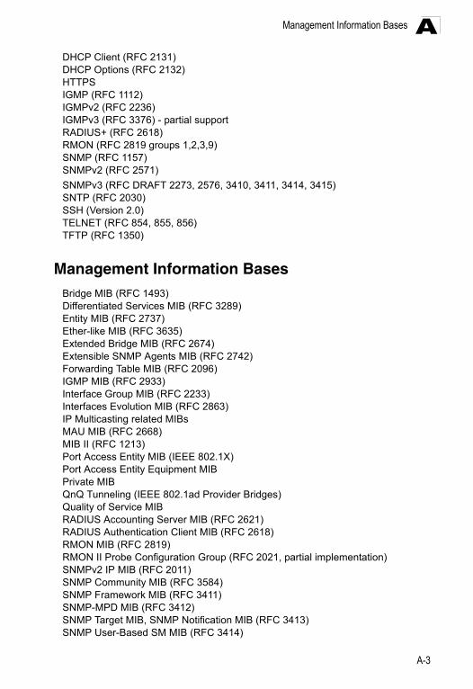
Management Information Bases A
DHCP Client (RFC 2131)DHCP Options (RFC 2132)HTTPS IGMP (RFC 1112)IGMPv2 (RFC 2236)IGMPv3 (RFC 3376) - partial supportRADIUS+ (RFC 2618)RMON (RFC 2819 groups 1,2,3,9)SNMP (RFC 1157)SNMPv2 (RFC 2571)SNMPv3 (RFC DRAFT 2273, 2576, 3410, 3411, 3414, 3415)SNTP (RFC 2030)SSH (Version 2.0)TELNET (RFC 854, 855, 856)TFTP (RFC 1350)
Management Information BasesBridge MIB (RFC 1493)Differentiated Services MIB (RFC 3289)Entity MIB (RFC 2737)Ether-like MIB (RFC 3635)Extended Bridge MIB (RFC 2674)Extensible SNMP Agents MIB (RFC 2742)Forwarding Table MIB (RFC 2096)IGMP MIB (RFC 2933)Interface Group MIB (RFC 2233)Interfaces Evolution MIB (RFC 2863)IP Multicasting related MIBs MAU MIB (RFC 2668)MIB II (RFC 1213)Port Access Entity MIB (IEEE 802.1X) Port Access Entity Equipment MIBPrivate MIBQnQ Tunneling (IEEE 802.1ad Provider Bridges)Quality of Service MIBRADIUS Accounting Server MIB (RFC 2621)RADIUS Authentication Client MIB (RFC 2618)RMON MIB (RFC 2819)RMON II Probe Configuration Group (RFC 2021, partial implementation)SNMPv2 IP MIB (RFC 2011)SNMP Community MIB (RFC 3584)SNMP Framework MIB (RFC 3411)SNMP-MPD MIB (RFC 3412)SNMP Target MIB, SNMP Notification MIB (RFC 3413)SNMP User-Based SM MIB (RFC 3414)
A-3

Software SpecificationsA
SNMP View Based ACM MIB (RFC 3415)TACACS+ Authentication Client MIBTCP MIB (RFC 2013)Trap (RFC 1215)UDP MIB (RFC 2013)A-4
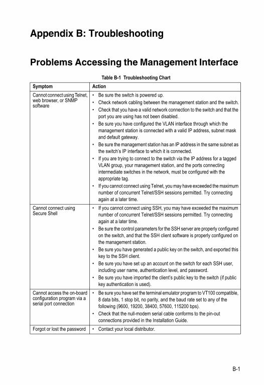
Appendix B: Troubleshooting
Problems Accessing the Management Interface
Table B-1 Troubleshooting Chart
Symptom Action
Cannot connect using Telnet, web browser, or SNMP software
• Be sure the switch is powered up.• Check network cabling between the management station and the switch.• Check that you have a valid network connection to the switch and that the
port you are using has not been disabled.• Be sure you have configured the VLAN interface through which the
management station is connected with a valid IP address, subnet mask and default gateway.
• Be sure the management station has an IP address in the same subnet as the switch’s IP interface to which it is connected.
• If you are trying to connect to the switch via the IP address for a tagged VLAN group, your management station, and the ports connecting intermediate switches in the network, must be configured with the appropriate tag.
• If you cannot connect using Telnet, you may have exceeded the maximum number of concurrent Telnet/SSH sessions permitted. Try connecting again at a later time.
Cannot connect using Secure Shell
• If you cannot connect using SSH, you may have exceeded the maximum number of concurrent Telnet/SSH sessions permitted. Try connecting again at a later time.
• Be sure the control parameters for the SSH server are properly configured on the switch, and that the SSH client software is properly configured on the management station.
• Be sure you have generated a public key on the switch, and exported this key to the SSH client.
• Be sure you have set up an account on the switch for each SSH user, including user name, authentication level, and password.
• Be sure you have imported the client’s public key to the switch (if public key authentication is used).
Cannot access the on-board configuration program via a serial port connection
• Be sure you have set the terminal emulator program to VT100 compatible, 8 data bits, 1 stop bit, no parity, and the baud rate set to any of the following (9600, 19200, 38400, 57600, 115200 bps).
• Check that the null-modem serial cable conforms to the pin-out connections provided in the Installation Guide.
Forgot or lost the password • Contact your local distributor.
B-1
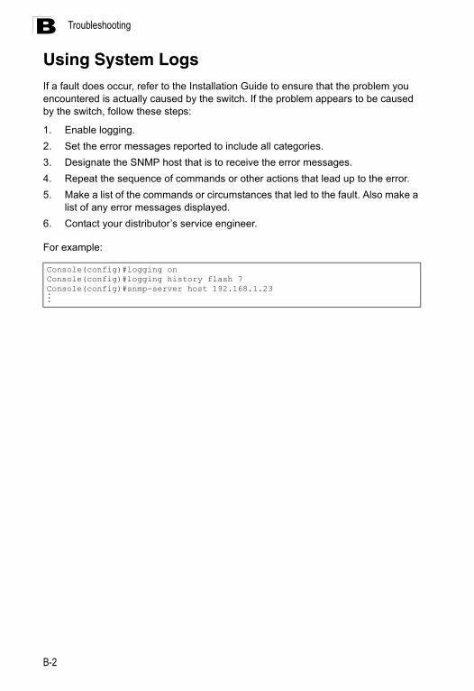
TroubleshootingB
Using System LogsIf a fault does occur, refer to the Installation Guide to ensure that the problem you encountered is actually caused by the switch. If the problem appears to be caused by the switch, follow these steps:1. Enable logging.
2. Set the error messages reported to include all categories.
3. Designate the SNMP host that is to receive the error messages.
4. Repeat the sequence of commands or other actions that lead up to the error.
5. Make a list of the commands or circumstances that led to the fault. Also make a list of any error messages displayed.
6. Contact your distributor’s service engineer.
For example:
Console(config)#logging onConsole(config)#logging history flash 7Console(config)#snmp-server host 192.168.1.23...
B-2
Glossary
Access Control List (ACL)ACLs can limit network traffic and restrict access to certain users or devices by checking each packet for certain IP or MAC (i.e., Layer 2) information.
Boot Protocol (BOOTP)
BOOTP is used to provide bootup information for network devices, including IP address information, the address of the TFTP server that contains the devices system files, and the name of the boot file.
Class of Service (CoS)CoS is supported by prioritizing packets based on the required level of service, and then placing them in the appropriate output queue. Data is transmitted from the queues using weighted round-robin service to enforce priority service and prevent blockage of lower-level queues. Priority may be set according to the port default, the packet’s priority bit (in the VLAN tag), TCP/UDP port number, or DSCP priority bit.
Differentiated Services (DiffServ)
DiffServ provides quality of service on large networks by employing a well-defined set of building blocks from which a variety of aggregate forwarding behaviors may be built. Each packet carries information (DS byte) used by each hop to give it a particular forwarding treatment, or per-hop behavior, at each network node. DiffServ allocates different levels of service to users on the network with mechanisms such as traffic meters, shapers/droppers, packet markers at the boundaries of the network.
Differentiated Services Code Point Service (DSCP)DSCP uses a six-bit tag to provide for up to 64 different forwarding behaviors. Based on network policies, different kinds of traffic can be marked for different kinds of forwarding. The DSCP bits are mapped to the Class of Service categories, and then into the output queues.
Domain Name Service (DNS)A system used for translating host names for network nodes into IP addresses.
Dynamic Host Control Protocol (DHCP)Provides a framework for passing configuration information to hosts on a TCP/IP network. DHCP is based on the Bootstrap Protocol (BOOTP), adding the capability of automatic allocation of reusable network addresses and additional configuration options.
Glossary-1
Glossary
DHCP SnoopingA technique used to enhance network security by snooping on DHCP server messages to track the physical location of hosts, ensure that hosts only use the IP addresses assigned to them, and ensure that only authorized DHCP servers are accessible.
Extensible Authentication Protocol over LAN (EAPOL) EAPOL is a client authentication protocol used by this switch to verify the network access rights for any device that is plugged into the switch. A user name and password is requested by the switch, and then passed to an authentication server (e.g., RADIUS) for verification. EAPOL is implemented as part of the IEEE 802.1X Port Authentication standard.
GARP VLAN Registration Protocol (GVRP)Defines a way for switches to exchange VLAN information in order to register necessary VLAN members on ports along the Spanning Tree so that VLANs defined in each switch can work automatically over a Spanning Tree network.
Generic Attribute Registration Protocol (GARP)GARP is a protocol that can be used by endstations and switches to register and propagate multicast group membership information in a switched environment so that multicast data frames are propagated only to those parts of a switched LAN containing registered endstations. Formerly called Group Address Registration Protocol.
Generic Multicast Registration Protocol (GMRP)GMRP allows network devices to register end stations with multicast groups. GMRP requires that any participating network devices or end stations comply with the IEEE 802.1p standard.
Group Attribute Registration Protocol (GARP)See Generic Attribute Registration Protocol.
IEEE 802.1DSpecifies a general method for the operation of MAC bridges, including the Spanning Tree Protocol.
IEEE 802.1QVLAN Tagging—Defines Ethernet frame tags which carry VLAN information. It allows switches to assign endstations to different virtual LANs, and defines a standard way for VLANs to communicate across switched networks.
Glossary-2
Glossary
IEEE 802.1pAn IEEE standard for providing quality of service (QoS) in Ethernet networks. The standard uses packet tags that define up to eight traffic classes and allows switches to transmit packets based on the tagged priority value.
IEEE 802.1sAn IEEE standard for the Multiple Spanning Tree Protocol (MSTP) which provides independent spanning trees for VLAN groups. (Now incorporated in IEEE 802.1D-2004)
IEEE 802.1wAn IEEE standard for the Rapid Spanning Tree Protocol (RSTP) which reduces the convergence time for network topology changes to about 10% of that required by the older IEEE 802.1D STP standard. (Now incorporated in IEEE 802.1D-2004)
IEEE 802.1XPort Authentication controls access to the switch ports by requiring users to first enter a user ID and password for authentication.
IEEE 802.3acDefines frame extensions for VLAN tagging.
IEEE 802.3xDefines Ethernet frame start/stop requests and timers used for flow control on full-duplex links. (Now incorporated in IEEE 802.3-2002)
IGMP QueryOn each subnetwork, one IGMP-capable device will act as the querier — that is, the device that asks all hosts to report on the IP multicast groups they wish to join or to which they already belong. The elected querier will be the device with the lowest IP address in the subnetwork.
IGMP SnoopingListening to IGMP Query and IGMP Report packets transferred between IP Multicast Routers and IP Multicast host groups to identify IP Multicast group members.
Internet Group Management Protocol (IGMP)A protocol through which hosts can register with their local router for multicast services. If there is more than one multicast switch/router on a given subnetwork, one of the devices is made the “querier” and assumes responsibility for keeping track of group membership.
In-Band ManagementManagement of the network from a station attached directly to the network.
Glossary-3
Glossary
IP Multicast FilteringA process whereby this switch can pass multicast traffic along to participating hosts.
IP PrecedenceThe Type of Service (ToS) octet in the IPv4 header includes three precedence bits defining eight different priority levels ranging from highest priority for network control packets to lowest priority for routine traffic. The eight values are mapped one-to-one to the Class of Service categories by default, but may be configured differently to suit the requirements for specific network applications.
Layer 2Data Link layer in the ISO 7-Layer Data Communications Protocol. This is related directly to the hardware interface for network devices and passes on traffic based on MAC addresses.
Link AggregationSee Port Trunk.
Link Aggregation Control Protocol (LACP)Allows ports to automatically negotiate a trunked link with LACP-configured ports on another device.
Management Information Base (MIB)An acronym for Management Information Base. It is a set of database objects that contains information about a specific device.
MD5 Message-Digest AlgorithmAn algorithm that is used to create digital signatures. It is intended for use with 32 bit machines and is safer than the MD4 algorithm, which has been broken. MD5 is a one-way hash function, meaning that it takes a message and converts it into a fixed string of digits, also called a message digest.
Multicast SwitchingA process whereby the switch filters incoming multicast frames for services for which no attached host has registered, or forwards them to all ports contained within the designated multicast VLAN group.
Multicast VLAN Registration (MVR)A method of using a single network-wide multicast VLAN to transmit common services, such as such as television channels or video-on-demand, across a service-provider’s network. MVR simplifies the configuration of multicast services by using a common VLAN for distribution, while still preserving security and data isolation for subscribers residing in both the MVR VLAN and other standard or private VLAN groups.
Glossary-4
Glossary
Multiple Spanning Tree Protocol (MSTP)MSTP can provide an independent spanning tree for different VLANs. It simplifies network management, provides for even faster convergence than RSTP by limiting the size of each region, and prevents VLAN members from being segmented from the rest of the group.
Network Time Protocol (NTP)NTP provides the mechanisms to synchronize time across the network. The time servers operate in a hierarchical-master-slave configuration in order to synchronize local clocks within the subnet and to national time standards via wire or radio.
Out-of-Band ManagementManagement of the network from a station not attached to the network.
Port AuthenticationSee IEEE 802.1X.
Port MirroringA method whereby data on a target port is mirrored to a monitor port for troubleshooting with a logic analyzer or RMON probe. This allows data on the target port to be studied unobstructively.
Port TrunkDefines a network link aggregation and trunking method which specifies how to create a single high-speed logical link that combines several lower-speed physical links.
Private VLANsPrivate VLANs provide port-based security and isolation between ports within the assigned VLAN. Data traffic on downlink ports can only be forwarded to, and from, uplink ports.
QinQ TunnelingQinQ is designed for service providers carrying traffic for multiple customers across their networks. It is used to maintain customer-specific VLAN and Layer 2 protocol configurations even when different customers use the same internal VLAN IDs.
Remote Authentication Dial-in User Service (RADIUS)
RADIUS is a logon authentication protocol that uses software running on a central server to control access to RADIUS-compliant devices on the network.
Glossary-5
Glossary
Remote Monitoring (RMON)RMON provides comprehensive network monitoring capabilities. It eliminates the polling required in standard SNMP, and can set alarms on a variety of traffic conditions, including specific error types.
Remote Switched Port Analyzer (RSPN)RSPAN can be used to mirror traffic from remote switches over a dedicated VLAN.
Rapid Spanning Tree Protocol (RSTP)
RSTP reduces the convergence time for network topology changes to about 10% of that required by the older IEEE 802.1D STP standard.
Secure Shell (SSH)A secure replacement for remote access functions, including Telnet. SSH can authenticate users with a cryptographic key, and encrypt data connections between management clients and the switch.
Simple Mail Transfer Protocol (SMTP)A standard host-to-host mail transport protocol that operates over TCP, port 25.
Simple Network Management Protocol (SNMP)The application protocol in the Internet suite of protocols which offers network management services.
Simple Network Time Protocol (SNTP)
SNTP allows a device to set its internal clock based on periodic updates from a Network Time Protocol (NTP) server. Updates can be requested from a specific NTP server, or can be received via broadcasts sent by NTP servers.
Spanning Tree Algorithm (STA)A technology that checks your network for any loops. A loop can often occur in complicated or backup linked network systems. Spanning Tree detects and directs data along the shortest available path, maximizing the performance and efficiency of the network.
TelnetDefines a remote communication facility for interfacing to a terminal device over TCP/IP.
Terminal Access Controller Access Control System Plus (TACACS+)TACACS+ is a logon authentication protocol that uses software running on a central server to control access to TACACS-compliant devices on the network.
Glossary-6
Glossary
Transmission Control Protocol/Internet Protocol (TCP/IP)Protocol suite that includes TCP as the primary transport protocol, and IP as the network layer protocol.
Trivial File Transfer Protocol (TFTP)A TCP/IP protocol commonly used for software downloads.
User Datagram Protocol (UDP)
UDP provides a datagram mode for packet-switched communications. It uses IP as the underlying transport mechanism to provide access to IP-like services. UDP packets are delivered just like IP packets – connection-less datagrams that may be discarded before reaching their targets. UDP is useful when TCP would be too complex, too slow, or just unnecessary.
Virtual LAN (VLAN)A Virtual LAN is a collection of network nodes that share the same collision domain regardless of their physical location or connection point in the network. A VLAN serves as a logical workgroup with no physical barriers, and allows users to share information and resources as though located on the same LAN.
XModemA protocol used to transfer files between devices. Data is grouped in 128-byte
blocks and error-corrected.
Glossary-7

Glossary
Glossary-8
Index
Numerics802.1Q tunnel 3-158, 4-223
access 3-163, 4-224configuration, guidelines 3-161configuration, limitations 3-160description 3-158ethernet type 3-162, 4-225interface configuration 3-162,
4-224–4-225mode selection 3-163, 4-224status, configuring 3-161, 4-224TPID 3-162, 4-225uplink 3-163, 4-224
802.1Xport authentication 3-65, 4-111port authentication accounting 4-94
AAAA
accounting 802.1X port settings 4-94
accounting exec command privileges 4-95
accounting exec settings 4-95accounting summary 4-97accounting update 4-94accounting, configuring 4-89authorization & accounting 4-89authorization exec settings 4-96authorization settings 4-96authorization summary 4-97RADIUS group settings 4-89TACACS+ group settings 4-89
acceptable frame type 3-156, 4-218Access Control List See ACLACL 3-76, 4-142
binding to a port 3-83, 4-147IP Extended 3-77, 3-79, 4-142,
4-145IP Standard 3-77, 3-78, 4-142,
4-144MAC 3-81, 4-148, 4-149–4-151
address table 3-119, 4-186aging time 3-121, 4-189
authenticationMAC 4-126MAC address authentication 4-126MAC, configuring ports 4-128network access 4-126public key 3-61, 4-103
BBOOTP 3-17, 4-291BPDU 3-122
selecting protocol based on message format 3-136, 4-206
broadcast storm, threshold 3-110, 4-161
CClass of Service See CoSCLI, showing commands 4-4clustering switches, management
access 3-217, 4-55command line interface See CLIcommunity ports 4-229community string 2-6, 3-37, 4-62community VLANs 4-230configuration files, restoring
defaults 3-21, 4-24configuration settings, saving or
restoring 2-9, 3-21, 4-24, 4-25console port, required connections 2-2CoS
configuring 3-170, 4-238DSCP 3-178, 4-246IP port priority 3-180, 4-244IP precedence 3-177, 4-245layer 3/4 priorities 3-176, 4-244queue mapping 3-172, 4-241queue mode 3-174, 4-239traffic class weights 3-175, 4-240,
4-243
Index-1
Index
Ddefault gateway, configuration 3-15,
4-292default priority, ingress port 3-170,
4-239default settings, system 1-6DHCP 3-17, 4-291
client 3-15, 4-291dynamic configuration 2-5
DHCP snoopingenabling 3-85, 4-131global configuration 3-85, 4-131information option 3-87, 4-135information option policy 3-87, 4-136information option, enabling 3-87,
4-135policy selection 3-87, 4-136specifying trusted interfaces 3-88,
4-133verifying MAC addresses 3-85,
4-134VLAN configuration 3-86, 4-132
Differentiated Code Point Service See DSCP
Differentiated Services See DiffServDiffServ 3-182, 4-251
binding policy to interface 3-188, 4-258
class map 3-182, 4-252, 4-255policy map 3-185, 4-255service policy 3-188, 4-258
DNSdefault domain name 3-212, 4-285displaying the cache 3-216, 4-289domain name list 3-212, 4-284enabling lookup 3-212, 4-288name server list 3-212, 4-287static entries 3-214, 4-284
Domain Name Service See DNSdownloading software 3-19, 4-25DSA encryption 3-62, 4-107DSCP
enabling 3-176, 4-246mapping priorities 3-178, 4-247
dynamic addresses, displaying 3-120, 4-188
Eedge port, STA 3-133, 3-136, 4-202encryption
DSA 3-62, 4-107RSA 3-62, 4-107
event logging 3-27, 4-39exec command privileges,
accounting 4-95exec settings
accounting 4-95authorization 4-96
Ffirmware
displaying version 3-12, 4-22upgrading 3-19, 4-25
GGARP VLAN Registration Protocol See
GVRPgateway, default 3-15, 4-292general security measures 3-74, 4-122GVRP
enabling 3-147, 4-210global setting 3-147, 4-210interface configuration 3-156, 4-211
Hhardware version, displaying 3-12,
4-22HTTPS 3-58, 3-59, 4-25, 4-99
configuring 3-58, 4-99, 4-100replacing SSL certificate 3-59, 4-25
HTTPS, secure server 3-58, 4-99
IIEEE 802.1D 3-122, 4-191IEEE 802.1s 3-122, 4-191IEEE 802.1w 3-122, 4-191IEEE 802.1X 3-65, 4-111
Index-2
Index
IGMPfilter profiles, configuration 3-200,
4-271filter, parameters 3-200, 4-271filtering & throttling, creating
profile 3-199, 4-272filtering & throttling, enabling 3-199,
4-271filtering & throttling, interface
configuration 3-202, 4-273filtering & throttling, status 3-199,
4-271filtering and throttling 3-199, 4-271groups, displaying 3-197, 4-264immediate leave, status 3-193,
4-263Layer 2 3-190, 4-260query 3-190, 3-191, 4-265snooping 3-190, 4-261snooping & query,
parameters 3-191snooping, configuring 3-191, 4-260
importing user public keys 4-25ingress filtering 3-156, 4-218IP address
BOOTP/DHCP 3-17, 4-291, 4-293setting 2-4, 3-15, 4-291
IP port priorityenabling 3-180, 4-244mapping priorities 3-180, 4-245
IP precedenceenabling 3-176, 4-245mapping priorities 3-177, 4-246
IP source guardconfiguring static entries 3-92, 4-140setting filter criteria 3-91, 4-138
Jjumbo frame 3-18, 4-23
Kkey
private 3-60, 4-102public 3-60, 4-102user public, importing 4-25
key pairhost 3-60, 4-102host, generating 3-62, 4-107
LLACP
group attributes, configuring 3-103, 4-172
group members, configuring 3-103local parameters 3-107, 4-174partner parameters 3-107, 4-174protocol message statistics 3-107,
4-174link type, STA 3-133, 3-136, 4-204logging
syslog traps 3-28, 4-43to syslog servers 3-29, 4-42
log-in, web interface 3-2logon authentication 3-52, 4-75
encryption keys 4-83, 4-87RADIUS client 3-55, 4-82RADIUS server 3-55, 4-82sequence 3-55, 4-80, 4-81settings 3-55, 4-80TACACS+ client 3-54, 4-85TACACS+ server 3-54, 4-85
MMAC address authentication 4-125
ports, configuring 4-126reauthentication 4-127
MAC authentication 4-126ports, configuring 4-128
main menu, web interface 3-4management access, filtering per
address 3-72, 4-120Management Information Bases
(MIBs) A-3media-type 3-98, 4-160mirror port, configuring local
traffic 3-112mirror port, configuring remote
traffic 4-180
Index-3
Index
MSTP 3-138, 4-191configuring 3-138, 4-196–4-207global settings, configuring 3-127,
3-138, 4-190, 4-197–4-199global settings, displaying 3-124,
4-207interface settings, configuring 3-134,
3-143, 4-190interface settings, displaying 3-141,
4-207path cost 3-143, 4-205
multicast filtering 3-189, 4-260multicast groups 3-197, 4-264
displaying 3-197, 4-264static 3-197, 4-261, 4-262, 4-264
multicast servicesconfiguring 3-198, 4-261, 4-262displaying 3-197, 4-264
multicast storm, threshold 4-161multicast, filtering and throttling 3-199,
4-271multicast, static router port 3-196,
4-178, 4-269MVR
configuring 3-205, 4-278description 3-204interface status, configuring 3-209,
4-280interface status, displaying 3-207,
4-281setting interface type 3-209, 4-280setting multicast groups 3-205,
4-278specifying a VLAN 3-205, 4-278using immediate leave 3-210, 4-280
Nnetwork access
authentication 4-125port configuration 4-126reauthentication 4-127secure MAC information 4-129
Ppassword, line 4-32
passwords 2-4administrator setting 3-52, 4-76
path cost 3-124, 3-133method 3-128, 4-195STA 3-124, 3-133, 4-195
port authentication 3-65, 4-111port priority
configuring 3-170, 4-238default ingress 3-170, 4-239STA 3-133, 4-202
port security, configuring 3-75, 4-123port, statistics 3-114, 4-164ports
autonegotiation 3-98, 4-157broadcast storm threshold 3-110,
4-161capabilities 3-98, 4-158configuring 3-95, 4-155duplex mode 3-97, 4-156flow control 3-97, 4-159forced selection on combo
ports 3-98, 4-160mirroring local traffic 3-112mirroring remote traffic 4-180multicast storm threshold 4-161speed 3-97, 4-156unknown unicast storm
threshold 4-161primary VLAN 4-230priority, default port ingress 3-170,
4-239private key 3-60, 4-102private VLANs, configuring 4-229,
4-230private VLANs, displaying 4-233privilege level, defining per
command 4-78problems, troubleshooting B-1profiles, IGMP filter 3-200, 4-272promiscuous ports 4-229protocol migration 3-136, 4-206protocol VLANs 3-166, 4-234
configuring 3-167, 4-235interface configuration 3-168, 4-235system configuration 3-168, 4-235
public key 3-60, 4-102PVID, port native VLAN 3-156, 4-219
Index-4
Index
PVLANassociation 4-231community ports 4-229configuring 4-229displaying 4-233interface configuration 3-168, 4-232primary VLAN 4-230promiscuous ports 4-229
QQinQ Tunneling See 802.1Q tunnelQoS 3-181, 4-251
configuring 3-182, 4-251Quality of Service See QoSqueue weights 3-175, 4-240, 4-243
RRADIUS
logon authentication 3-55, 4-80, 4-82
settings 3-55, 4-82rate limits, setting 3-113, 4-185remote logging 3-28, 4-43restarting the system 3-32, 4-13RSA encryption 3-62, 4-107RSTP 3-122, 4-191
global settings, configuring 3-127, 4-191
global settings, displaying 3-124, 4-207
interface settings, configuring 3-134, 4-200–4-206
interface settings, displaying 3-131, 4-207
running configuration filesdisplaying 4-18
Ssecure shell 3-60, 4-102
configuration 3-60, 4-102security, general measures 3-74,
4-122serial port, configuring 3-23, 4-30Simple Mail Transfer Protocol See
SMTP
Simple Network Management Protocol See SNMP
SMTP, sending log events 3-30, 4-46SNMP 3-35, 4-60
community string 3-37, 4-62enabling traps 3-38, 4-66engine identifier, local 3-41, 4-67engine identifier, remote 3-42, 4-67filtering IP addresses 3-72, 4-120groups 3-47, 4-70trap manager 3-38, 4-64users, configuring 3-43, 3-45views 3-50, 4-68
SNTP, setting the system clock 3-33, 4-50–4-52
softwaredisplaying version 3-12, 4-22downloading 3-19, 4-25
Spanning Tree Protocol See STAspecifications, software A-1SSH 3-60, 4-102
configuring 3-60, 4-102server, configuring 3-64, 4-104
SSL, replacing certificate 3-59, 4-25STA 3-122, 4-190
edge port 3-133, 3-136, 4-202global settings, configuring 3-127,
4-191–4-196global settings, displaying 3-124,
4-207interface settings, configuring 3-134,
4-200–4-206interface settings, displaying 3-131,
4-207link type 3-133, 3-136, 4-204MSTP path cost 3-143, 4-205MSTP settings, configuring 3-143,
4-196–4-199path cost 3-124, 3-133, 4-200path cost method 3-128, 4-195port priority 3-133, 4-202protocol migration 3-136, 4-206transmission limit 3-129, 4-196
standards, IEEE A-2
Index-5
Index
startup filescreating 3-22, 4-29displaying 3-19, 4-17setting 3-19, 4-29
static addresses, setting 3-119, 4-186statistics
port 3-114, 4-164STP 3-127, 4-191STP Also see STAsummary, accounting 4-97switch clustering, for
management 3-217, 4-55switch settings
restoring 3-21, 4-24saving 4-24
system clocksetting 3-33, 4-50setting manually 3-33, 4-54setting the time zone 3-34, 4-53setting with SNTP 3-33, 4-50–4-52
system logs 3-27, 4-40system software, downloading from
server 3-19, 4-25
TTACACS+
logon authentication 3-54, 4-85settings 3-55, 4-85
Telnet server, enabling 3-25, 4-101throttling, IGMP 3-199, 4-271time zone, setting 3-34, 4-53time, setting 3-33, 4-50TPID 3-162, 4-225traffic class weights 3-175, 4-240,
4-243traffic segmentation 4-227
enabling 4-227trap manager 2-7, 3-38, 4-64troubleshooting B-1trunk
configuration 3-99, 4-167LACP 3-101, 4-169static 3-100, 4-168
Uunknown unicast storm,
threshold 4-161upgrading software 3-19, 4-25user password 3-52, 4-76, 4-77
VVLANs 3-144–3-166, ??–3-170,
4-209–4-222802.1Q tunnel mode 3-163, 4-224adding static members 3-153,
3-155, 4-220creating 3-150, 4-215description 3-144, 3-170displaying basic information 3-148,
4-211displaying port members 3-149,
4-222egress mode 3-157, 4-217interface configuration 3-156,
4-218–4-221private 3-165, 4-229protocol 3-166, 4-234protocol, configuring 3-167, 4-235protocol, configuring groups 3-167,
4-235protocol, interface
configuration 3-168, 4-235protocol, system
configuration 3-168, 4-235PVID 3-156, 4-219system mode, QinQ 3-161, 4-224
WWeb interface
access requirements 3-1web interface
configuration buttons 3-3home page 3-2menu list 3-4panel display 3-3
Index-6


SF-0422GSF-0446GE112009/MW-R01