Embed Size (px)
Citation preview

Key Features & Benefits: • No Physical Connection Between
Motor and Load • No Lubrication Required • Lowest Total Cost of Ownership • Efficient Torque Transfer • Accepts Misalignment • Cushioned and Delay Start • Torque Limiting to Protect Equipment • Eliminates Vibration Transfer
Between Motor and Load • Permits Shock Loading • Low Maintenance • Simple Installation & Operation • Increases Seal & Bearing Life • “Green” Technology
Ideal for Applications Subject to: • Vibration • Periodic Load Seizure • Pulsating Loads • Thermal Expansion • Shock Loading • Tight Space Constraints • Fluid Coupling Problems
MGD / MGTL
MagnaGuard Delay & Torque Limiting
Couplings
10 — 2,000 Hp
Principle of Operation
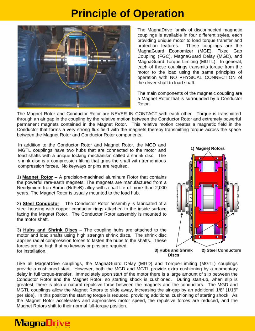
The MagnaDrive family of disconnected magnetic couplings is available in four different styles, each providing unique motor to load torque transfer and protection features. These couplings are the MagnaGuard Economizer (MGE), Fixed Gap Coupling (FGC), MagnaGuard Delay (MGD), and MagnaGuard Torque Limiting (MGTL). In general, each of these couplings transmits torque from the motor to the load using the same principles of operation with NO PHYSICAL CONNECTION of the driver shaft to load shaft. The main components of the magnetic coupling are a Magnet Rotor that is surrounded by a Conductor Rotor.
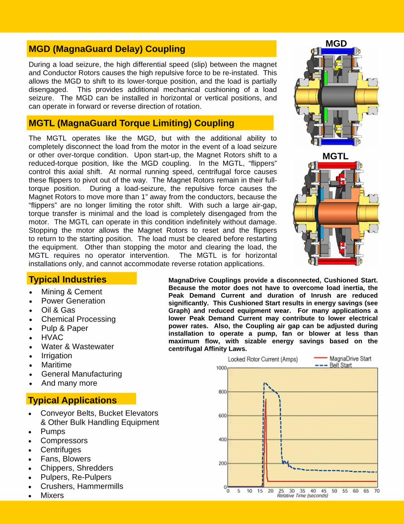
1) Magnet Rotor – A precision-machined aluminum Rotor that contains the powerful rare-earth magnets. The magnets are manufactured from a Neodymium-Iron-Boron (NdFeB) alloy with a half-life of more than 2,000 years. The Magnet Rotor is usually mounted to the load hub. 2) Steel Conductor – The Conductor Rotor assembly is fabricated of a steel housing with copper conductor rings attached to the inside surface facing the Magnet Rotor. The Conductor Rotor assembly is mounted to the motor shaft. 3) Hubs and Shrink Discs – The coupling hubs are attached to the motor and load shafts using high strength shrink discs. The shrink disc applies radial compression forces to fasten the hubs to the shafts. These forces are so high that no keyway or pins are required for installation.
1) Magnet Rotors
2) Steel Conductors 3) Hubs and Shrink Discs
Like all MagnaDrive couplings, the MagnaGuard Delay (MGD) and Torque-Limiting (MGTL) couplings provide a cushioned start. However, both the MGD and MGTL provide extra cushioning by a momentary delay in full torque-transfer. Immediately upon start of the motor there is a large amount of slip between the Conductor Rotor and the Magnet Rotor, so starting shock is cushioned. During start-up, when slip is greatest, there is also a natural repulsive force between the magnets and the conductors. The MGD and MGTL couplings allow the Magnet Rotors to slide away, increasing the air-gap by an additional 1/8” (1/16” per side). In this position the starting torque is reduced, providing additional cushioning of starting shock. As the Magnet Rotor accelerates and approaches motor speed, the repulsive forces are reduced, and the Magnet Rotors shift to their normal full-torque position.
The Magnet Rotor and Conductor Rotor are NEVER IN CONTACT with each other. Torque is transmitted through an air gap in the coupling by the relative motion between the Conductor Rotor and extremely powerful permanent magnets contained in the Magnet Rotor. This relative motion creates a magnetic field in the Conductor that forms a very strong flux field with the magnets thereby transmitting torque across the space between the Magnet Rotor and Conductor Rotor components.
In addition to the Conductor Rotor and Magnet Rotor, the MGD and MGTL couplings have two hubs that are connected to the motor and load shafts with a unique locking mechanism called a shrink disc. The shrink disc is a compression fitting that grips the shaft with tremendous compression forces. No keyways or pins are required.
MGD
MGTL
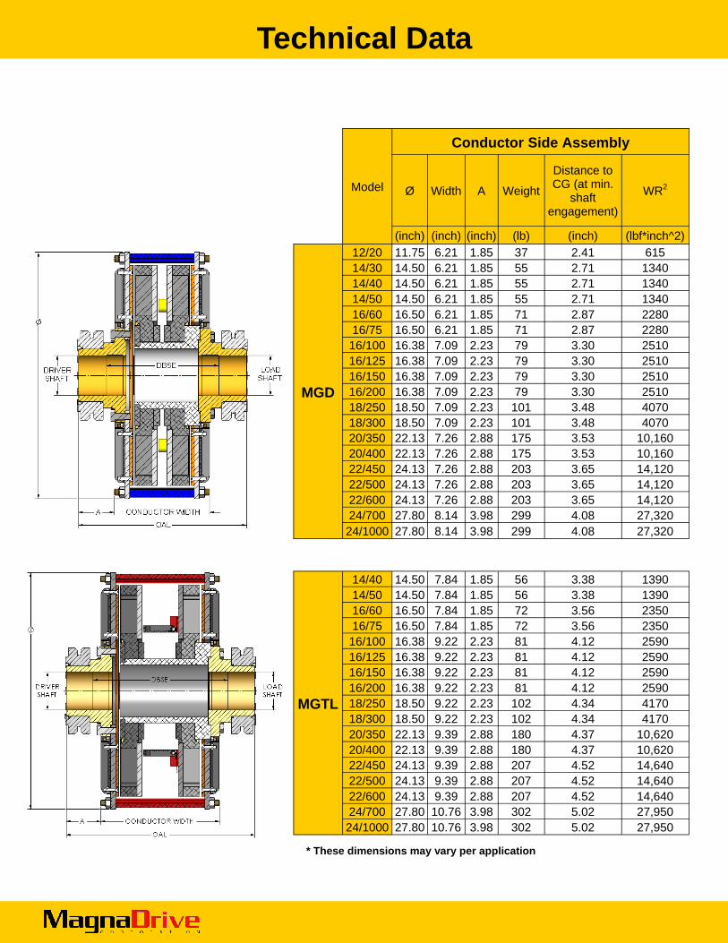
During a load seizure, the high differential speed (slip) between the magnet and Conductor Rotors causes the high repulsive force to be re-instated. This allows the MGD to shift to its lower-torque position, and the load is partially disengaged. This provides additional mechanical cushioning of a load seizure. The MGD can be installed in horizontal or vertical positions, and can operate in forward or reverse direction of rotation.
The MGTL operates like the MGD, but with the additional ability to completely disconnect the load from the motor in the event of a load seizure or other over-torque condition. Upon start-up, the Magnet Rotors shift to a reduced-torque position, like the MGD coupling. In the MGTL, “flippers” control this axial shift. At normal running speed, centrifugal force causes these flippers to pivot out of the way. The Magnet Rotors remain in their full-torque position. During a load-seizure, the repulsive force causes the Magnet Rotors to move more than 1” away from the conductors, because the “flippers” are no longer limiting the rotor shift. With such a large air-gap, torque transfer is minimal and the load is completely disengaged from the motor. The MGTL can operate in this condition indefinitely without damage. Stopping the motor allows the Magnet Rotors to reset and the flippers to return to the starting position. The load must be cleared before restarting the equipment. Other than stopping the motor and clearing the load, the MGTL requires no operator intervention. The MGTL is for horizontal installations only, and cannot accommodate reverse rotation applications.
MGD (MagnaGuard Delay) Coupling
MGTL (MagnaGuard Torque Limiting) Coupling
• Conveyor Belts, Bucket Elevators & Other Bulk Handling Equipment
• Pumps • Compressors • Centrifuges • Fans, Blowers • Chippers, Shredders • Pulpers, Re-Pulpers • Crushers, Hammermills • Mixers
Typical Industries • Mining & Cement • Power Generation • Oil & Gas • Chemical Processing • Pulp & Paper • HVAC • Water & Wastewater • Irrigation • Maritime • General Manufacturing • And many more
Typical Applications
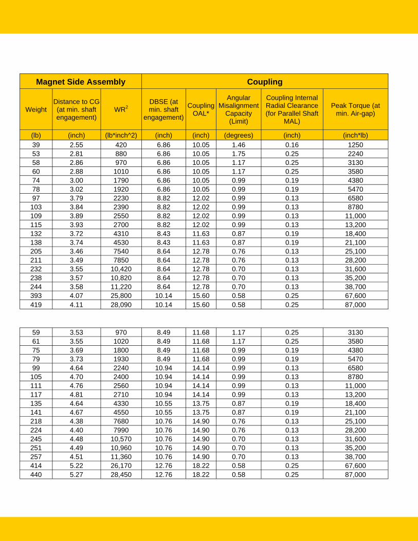
MagnaDrive Couplings provide a disconnected, Cushioned Start. Because the motor does not have to overcome load inertia, the Peak Demand Current and duration of Inrush are reduced significantly. This Cushioned Start results in energy savings (see Graph) and reduced equipment wear. For many applications a lower Peak Demand Current may contribute to lower electrical power rates. Also, the Coupling air gap can be adjusted during installation to operate a pump, fan or blower at less than maximum flow, with sizable energy savings based on the centrifugal Affinity Laws.
Technical Data
* These dimensions may vary per application
Conductor Side Assembly
Ø Width A Weight
Distance to CG (at min.
shaft engagement)
WR2
(inch) (inch) (inch) (lb) (inch) (lbf*inch^2)
MGD
12/20 11.75 6.21 1.85 37 2.41 615 14/30 14.50 6.21 1.85 55 2.71 1340 14/40 14.50 6.21 1.85 55 2.71 1340 14/50 14.50 6.21 1.85 55 2.71 1340 16/60 16.50 6.21 1.85 71 2.87 2280 16/75 16.50 6.21 1.85 71 2.87 2280 16/100 16.38 7.09 2.23 79 3.30 2510 16/125 16.38 7.09 2.23 79 3.30 2510 16/150 16.38 7.09 2.23 79 3.30 2510 16/200 16.38 7.09 2.23 79 3.30 2510 18/250 18.50 7.09 2.23 101 3.48 4070 18/300 18.50 7.09 2.23 101 3.48 4070 20/350 22.13 7.26 2.88 175 3.53 10,160 20/400 22.13 7.26 2.88 175 3.53 10,160 22/450 24.13 7.26 2.88 203 3.65 14,120 22/500 24.13 7.26 2.88 203 3.65 14,120 22/600 24.13 7.26 2.88 203 3.65 14,120 24/700 27.80 8.14 3.98 299 4.08 27,320 24/1000 27.80 8.14 3.98 299 4.08 27,320
MGTL
14/40 14.50 7.84 1.85 56 3.38 1390 14/50 14.50 7.84 1.85 56 3.38 1390 16/60 16.50 7.84 1.85 72 3.56 2350 16/75 16.50 7.84 1.85 72 3.56 2350 16/100 16.38 9.22 2.23 81 4.12 2590 16/125 16.38 9.22 2.23 81 4.12 2590 16/150 16.38 9.22 2.23 81 4.12 2590 16/200 16.38 9.22 2.23 81 4.12 2590 18/250 18.50 9.22 2.23 102 4.34 4170 18/300 18.50 9.22 2.23 102 4.34 4170 20/350 22.13 9.39 2.88 180 4.37 10,620 20/400 22.13 9.39 2.88 180 4.37 10,620 22/450 24.13 9.39 2.88 207 4.52 14,640 22/500 24.13 9.39 2.88 207 4.52 14,640 22/600 24.13 9.39 2.88 207 4.52 14,640 24/700 27.80 10.76 3.98 302 5.02 27,950 24/1000 27.80 10.76 3.98 302 5.02 27,950
Model
Magnet Side Assembly Coupling
Weight Distance to CG (at min. shaft engagement)
WR2 DBSE (at min. shaft
engagement)
Coupling OAL*
Angular Misalignment
Capacity (Limit)
Coupling Internal Radial Clearance (for Parallel Shaft
MAL)
Peak Torque (at min. Air-gap)
(lb) (inch) (lb*inch^2) (inch) (inch) (degrees) (inch) (inch*lb) 39 2.55 420 6.86 10.05 1.46 0.16 1250 53 2.81 880 6.86 10.05 1.75 0.25 2240 58 2.86 970 6.86 10.05 1.17 0.25 3130 60 2.88 1010 6.86 10.05 1.17 0.25 3580 74 3.00 1790 6.86 10.05 0.99 0.19 4380 78 3.02 1920 6.86 10.05 0.99 0.19 5470 97 3.79 2230 8.82 12.02 0.99 0.13 6580
103 3.84 2390 8.82 12.02 0.99 0.13 8780 109 3.89 2550 8.82 12.02 0.99 0.13 11,000 115 3.93 2700 8.82 12.02 0.99 0.13 13,200 132 3.72 4310 8.43 11.63 0.87 0.19 18,400 138 3.74 4530 8.43 11.63 0.87 0.19 21,100 205 3.46 7540 8.64 12.78 0.76 0.13 25,100 211 3.49 7850 8.64 12.78 0.76 0.13 28,200 232 3.55 10,420 8.64 12.78 0.70 0.13 31,600 238 3.57 10,820 8.64 12.78 0.70 0.13 35,200 244 3.58 11,220 8.64 12.78 0.70 0.13 38,700 393 4.07 25,800 10.14 15.60 0.58 0.25 67,600 419 4.11 28,090 10.14 15.60 0.58 0.25 87,000
59 3.53 970 8.49 11.68 1.17 0.25 3130 61 3.55 1020 8.49 11.68 1.17 0.25 3580 75 3.69 1800 8.49 11.68 0.99 0.19 4380 79 3.73 1930 8.49 11.68 0.99 0.19 5470 99 4.64 2240 10.94 14.14 0.99 0.13 6580
105 4.70 2400 10.94 14.14 0.99 0.13 8780 111 4.76 2560 10.94 14.14 0.99 0.13 11,000 117 4.81 2710 10.94 14.14 0.99 0.13 13,200 135 4.64 4330 10.55 13.75 0.87 0.19 18,400 141 4.67 4550 10.55 13.75 0.87 0.19 21,100 218 4.38 7680 10.76 14.90 0.76 0.13 25,100 224 4.40 7990 10.76 14.90 0.76 0.13 28,200 245 4.48 10,570 10.76 14.90 0.70 0.13 31,600 251 4.49 10,960 10.76 14.90 0.70 0.13 35,200 257 4.51 11,360 10.76 14.90 0.70 0.13 38,700 414 5.22 26,170 12.76 18.22 0.58 0.25 67,600 440 5.27 28,450 12.76 18.22 0.58 0.25 87,000

Total Cost of Ownership (TCO)
Fluid Couplings
Rigid Couplings
Disk Couplings MGD/MGTL
Direct Coupled Yes Yes Yes No
First Cost High Low Medium Medium
Total Cost of Ownership High High High Low
Environmental Issues
Oil leak /contamination and
oil disposal problems
Uses grease na None. Completely
clean / Green technology
Installation Issues
Usually very heavy and bulky
equipment requiring extra labor and time to install as well as setting-up oil levels
Time spent with alignment
Time spent with alignment Easy to install
Space Requirements High Low Low
Less than Fluid Couplings
Easy to retrofit into existing Fluid Coupling
Installations
Alignment Issues Needs periodic laser alignment
Needs periodic laser alignment
Needs periodic laser alignment None
Overload Torque Protection
Some, but likely will melt / blow off
fusible plug ejecting oil
No No Yes
Cushioned / Delay Start Moderate No No Yes
Conveyor Delay Start Feature
Difficult to control Belt Uplift and
prone to overtorque / oil spill
No No Minimizes Belt Uplift
and overtorque during startup
System / Maintenance Requirements
Medium Requires spare
parts and oil
High Requires spare
parts
High Requires spare
parts Low
Equipment Life Issues Vibration transfer
causes lower equipment life
Vibration transfer causes lower equipment life
Vibration transfer causes lower equipment life
MagnaDrive offers the longest life on bearings,
seals, and other equipment
MagnaDrive’s “Green” disconnected torque-transfer technology reduces your total cost of ownership by lowering maintenance and
operating costs, increasing process availability, and improving system reliability.

Sample Installations
MGD 20/400, 300HP, 1800RPM, Mining, Gear Box in Bulk Conveyor System, AZ, USA MGD 18/250, 150HP, 1500RPM, Iron Mill, Australia
MGTL 18/250, 240HP, 1800RPM, Mining, Conveyor System, UT,USA MGTL 12/20, Power Generation, Conveyor System, TX, USA
MGD 16/125, 55HP, 1480RPM, Mining, Bulk Material Handling Conveyor System, Australia
MGD 18/250, 150HP, 1500RPM, Steel Mill, Conveyor System, Australia
MagnaDrive Corporation 600 108th Avenue NE, Suite 1014, Bellevue, Washington 98004
Tel. (425) 463-4700 Fax (425) 463-4747 [email protected] / www.magnadrive.com
MagnaDrive is a trademark of MagnaDrive Corporation. © MagnaDrive Corp. All rights reserved.
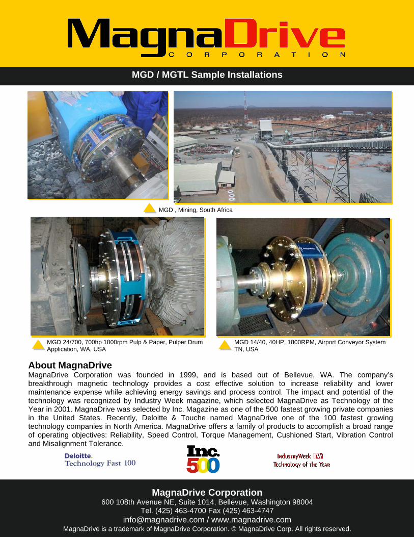
MGD / MGTL Sample Installations
About MagnaDrive MagnaDrive Corporation was founded in 1999, and is based out of Bellevue, WA. The company’s breakthrough magnetic technology provides a cost effective solution to increase reliability and lower maintenance expense while achieving energy savings and process control. The impact and potential of the technology was recognized by Industry Week magazine, which selected MagnaDrive as Technology of the Year in 2001. MagnaDrive was selected by Inc. Magazine as one of the 500 fastest growing private companies in the United States. Recently, Deloitte & Touche named MagnaDrive one of the 100 fastest growing technology companies in North America. MagnaDrive offers a family of products to accomplish a broad range of operating objectives: Reliability, Speed Control, Torque Management, Cushioned Start, Vibration Control and Misalignment Tolerance.
MGD , Mining, South Africa
MGD 24/700, 700hp 1800rpm Pulp & Paper, Pulper Drum Application, WA, USA
MGD 14/40, 40HP, 1800RPM, Airport Conveyor System TN, USA