Embed Size (px)
Citation preview


2 Mexico Super CF 3/60P - 3/140P - Installation
Mexico:
The Floor Standing Gas Boiler
The Ideal Mexico is a range of cast iron floor standing gas central heating boilers. Bothbalanced or conventional flue versions are available. A complete range of both naturalgas and propane models. The range offers Super models and, for when space is tight,there are Slimline models available.
Mexico: Britain’s biggest selling floor standing boiler
The ideal replacement boiler...Easy to install, easy to operate and easy to service. The Ideal Mexico really is the ultimatereplacement floor standing range - you can depend on it.
Proven reliability...Proven cast iron heat exchanger engineered and refined to be the most dependable floorstanding boiler ensuring totally calm operation and quiet running, whatever the systemdemands.
Complete range...27 models, including 4 Slimline models at only 250mm wide and 8 propane Super models.Option kit availability includes an easy to use programmer kit available on all models, anoverheat thermostat kit for all models and a pump kit that can be housed within thecasing, available for all models except the Super CF 3/140 & CF 3/140P.
Full system suitability...All models are suitable for connection to pumped open vent central heating systems,pumped central heating combined with pumped or gravity indirect domestic hot watersupply systems. They can also be used on sealed water systems when used in conjunctionwith the optional Overheat Thermostat Kit.
Free Guarantee: 1st Year Ideal CareThe home owner is entitled to 12 months free Ideal Care, which includes both parts andlabour, to restore the boiler to full function. Please encourage the home owner to completeand return the registration form in their Householder’s pack within 30 days of installation.
Optional Extra Year Cover with Ideal CareYou may wish to offer your own annual service plan or you may wish to advise the homeowner to complete their application form for the appropriate level of extended Ideal Care -Silver, Gold or Platinum. Full details are available in the Ideal Care brochure.
CAUTION. To avoid the possibility of injury during the installation, servicing or cleaningof this appliance, care should be taken when handling edges of sheet steel components.

3Mexico Super CF 3/60P - 3/140P - Installation
Boiler Size CF 3/60P CF 3/75P CF 3/100P CF 3/125P CF 3/140P
Gas Supply Connection in. BSP Rc 1/2 (1/2) Rc 3/4 (3/4)
Number of Boiler Sections 3 3 4 5 6
Flow and Return Connections Rc 1 (1" BSP)
MAXIMUM Static Water Head m (ft.) 30.5 (100) (3 bar)
MINIMUM Static Water Head m (ft.) 1.0 (3.3)
Electrical Supply 230 V ~ 50 Hz
External Fuse Rating (Power Consumption) 3 A (5 W)
Water Content litre (gal.) 7.4 (1.6) 7.4 (1.6) 9.8 (2.1) 12.2 (2.7) 14.6 (3.2)
Dry Weight kg. (lb.) 89 (196) 89 (196) 111 (245) 134 (295) 157 (346)
Boiler Size Height mm (in.) 850 (33.5)
Width mm (in.) 440. (17.4)
Depth mm (in.) 533 (21.0) 533 (21.0) 533 (21.0) 600 (23.6) 750 (29.5)
Gas Type II 2H 3P
Flue Connection mm (in.) 100 (4) 125 (5) 150 (6)
Table 1 - Boiler Data
GENERAL
Boiler Size CF 3/60P CF 3/75P CF 3/100P CF 3/125P CF 3/140P
Boiler InputNOMINAL kW (Btu/h) 22.1 ( 75 400) 27.3 (93 100) 35.8 (122 100) 43.4 (148 100) 53.5 (182 500)Gas Consumption l/s (ft.3/h) 0.246 (31.8) 0.287 (37.1) 0.377 (48.8) 0.457 (59.2) 0.563 (72.9)
Boiler Output to Water
NOMINAL kW (Btu/h) 18.1 (61 600) 22.2 (75 800) 29.3 (100 000) 35.6 (121 600) 44.3 (151 100)
Burner Setting Pressure (hot)NOMINAL mbar (in w.g.) 35.4 (14.2) 35.0 (14) 35.0 (14) 35.1 (14) 34.9 (14)
Inlet PressureNOMINAL mbar (in w.g.) 37.0 (14.8) 37.0 (14.8) 37.0 (14.8) 37.0 (14.8) 37.0 (14.8)
Flue Gas Flow Rate g/s 10.6 13.1 17.2 20.8 25.7
Flue Gas Temperature oC 125 134 129 140 132
Seasonal Efficiency(SEDBUK)* % 72.7 72.3 72.0 72.8 73.0
Table 2 - Performance Data
Notes.1. Gas consumption is calculated using a calorific value of 95.0
MJ/m3 (2500 Btu/ft.3.)
2. To obtain the fuel consumption in liquid form divide the abovefigures by 270.
3. The appliance is pre-set at the factory to give the nominaloutput at an inlet pressure of 37 mbar (14.8 in.w.g.)
4. A conversion kit is available to convert this appliance for useon natural gas. This kit contains all parts and istructions forsetting up on natural gas. Once converted it is not possibleto convert back to propane.
Key to symbols
GB = United Kingdom IE = Ireland (Countries of destination)
PMS = Maximum operating pressure of waterB11BS = An appliance designed for connection to a flue
discharging the products of combustion outside the room,with air for combustion being drawn directly from theroom where the appliance is installed, without a fan inthe combustion products circuit and fitted with acombustion products discharge safety device.
II2H3P = An appliance designed for use on 2nd Family gas, GroupH and 3rd Family gas, Group P.
*The value is used in the UK government's Standard Assessment Procedure (SAP) for energy rating of dwellings.The test data from which it has been calculated have been certified by BGplc 0087)
4 Mexico Super CF 3/60P - 3/140P - Installation
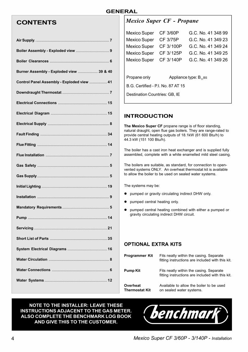
The Mexico Super CF propane range is of floor standing,natural draught, open flue gas boilers. They are range-rated toprovide central heating outputs of 18.1kW (61 600 Btu/h) to44.3 kW (151 100 Btu/h).
The boiler has a cast iron heat exchanger and is supplied fullyassembled, complete with a white enamelled mild steel casing.
The boilers are suitable, as standard, for connection to open-vented systems ONLY. An overheat thermostat kit is availableto allow the boiler to be used on sealed water systems.
The systems may be:
pumped or gravity circulating indirect DHW only.
pumped central heating only.
pumped central heating combined with either a pumped orgravity circulating indirect DHW circuit.
OPTIONAL EXTRA KITS
Programmer Kit Fits neatly within the casing. Separatefitting instructions are included with this kit.
Pump Kit Fits neatly within the casing. Separatefitting instructions are included with this kit.
Overheat Available to allow the boiler to be usedThermostat Kit on sealed water systems.
GENERAL
CONTENTS
Air Supply. ...................................................................... 7
Boiler Assembly - Exploded view ................................ 9
Boiler Clearances ......................................................... 6
Burner Assembly - Exploded view ................... 39 & 40
Control Panel Assembly - Exploded view ................. 41
Downdraught Thermostat ............................................. 7
Electrical Connections ............................................... 15
Electrical Diagram ...................................................... 15
Electrical Supply ........................................................... 8
Fault Finding ................................................................ 34
Flue Fitting ................................................................... 14
Flue Installation ............................................................. 7
Gas Safety ..................................................................... 5
Gas Supply ..................................................................... 5
Initial Lighting ............................................................... 19
Installation ..................................................................... 9
Mandatory Requirements ............................................. 5
Pump ............................................................................ 14
Servicing ...................................................................... 21
Short List of Parts ....................................................... 35
System Electrical Diagrams ...................................... 16
Water Circulation .......................................................... 8
Water Connections ....................................................... 6
Water Systems ............................................................ 12
Mexico Super CF 3/60P G.C. No. 41 348 99Mexico Super CF 3/75P G.C. No. 41 349 23Mexico Super CF 3/100P G.C. No. 41 349 24Mexico Super CF 3/125P G.C. No. 41 349 25Mexico Super CF 3/140P G.C. No. 41 349 26
Mexico Super CF - Propane
INTRODUCTION
Propane only Appliance type: B11BS
B.G. Certified - P.I. No. 87 AT 15
Destination Countries: GB, IE
NOTE TO THE INSTALLER: LEAVE THESEINSTRUCTIONS ADJACENT TO THE GAS METER.ALSO COMPLETE THE BENCHMARK LOG BOOK
AND GIVE THIS TO THE CUSTOMER.
5Mexico Super CF 3/60P - 3/140P - Installation
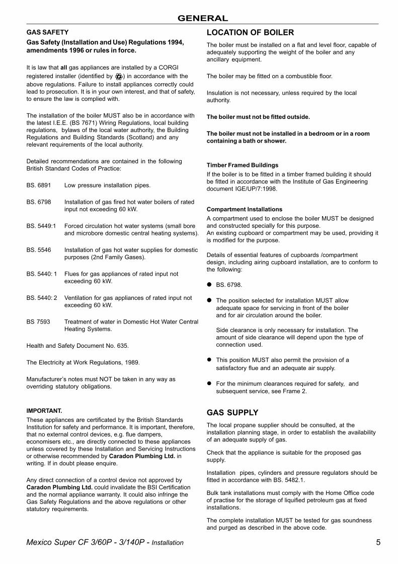
GENERALLOCATION OF BOILERThe boiler must be installed on a flat and level floor, capable ofadequately supporting the weight of the boiler and anyancillary equipment.
The boiler may be fitted on a combustible floor.
Insulation is not necessary, unless required by the localauthority.
The boiler must not be fitted outside.
The boiler must not be installed in a bedroom or in a roomcontaining a bath or shower.
Timber Framed BuildingsIf the boiler is to be fitted in a timber framed building it shouldbe fitted in accordance with the Institute of Gas Engineeringdocument IGE/UP/7:1998.
Compartment InstallationsA compartment used to enclose the boiler MUST be designedand constructed specially for this purpose.An existing cupboard or compartment may be used, providing itis modified for the purpose.
Details of essential features of cupboards /compartmentdesign, including airing cupboard installation, are to conform tothe following:
BS. 6798.
The position selected for installation MUST allowadequate space for servicing in front of the boilerand for air circulation around the boiler.
Side clearance is only necessary for installation. Theamount of side clearance will depend upon the type ofconnection used.
This position MUST also permit the provision of asatisfactory flue and an adequate air supply.
For the minimum clearances required for safety, andsubsequent service, see Frame 2.
GAS SUPPLYThe local propane supplier should be consulted, at theinstallation planning stage, in order to establish the availabilityof an adequate supply of gas.
Check that the appliance is suitable for the proposed gassupply.
Installation pipes, cylinders and pressure regulators should befitted in accordance with BS. 5482.1.
Bulk tank installations must comply with the Home Office codeof practise for the storage of liquified petroleum gas at fixedinstallations.
The complete installation MUST be tested for gas soundnessand purged as described in the above code.
GAS SAFETYGas Safety (Installation and Use) Regulations 1994,amendments 1996 or rules in force.
It is law that all gas appliances are installed by a CORGIregistered installer (identified by ) in accordance with theabove regulations. Failure to install appliances correctly couldlead to prosecution. It is in your own interest, and that of safety,to ensure the law is complied with.
The installation of the boiler MUST also be in accordance withthe latest I.E.E. (BS 7671) Wiring Regulations, local buildingregulations, bylaws of the local water authority, the BuildingRegulations and Building Standards (Scotland) and anyrelevant requirements of the local authority.
Detailed recommendations are contained in the followingBritish Standard Codes of Practice:
BS. 6891 Low pressure installation pipes.
BS. 6798 Installation of gas fired hot water boilers of ratedinput not exceeding 60 kW.
BS. 5449:1 Forced circulation hot water systems (small boreand microbore domestic central heating systems).
BS. 5546 Installation of gas hot water supplies for domesticpurposes (2nd Family Gases).
BS. 5440: 1 Flues for gas appliances of rated input notexceeding 60 kW.
BS. 5440: 2 Ventilation for gas appliances of rated input notexceeding 60 kW.
BS 7593 Treatment of water in Domestic Hot Water CentralHeating Systems.
Health and Safety Document No. 635.
The Electricity at Work Regulations, 1989.
Manufacturer’s notes must NOT be taken in any way asoverriding statutory obligations.
IMPORTANT.These appliances are certificated by the British StandardsInstitution for safety and performance. It is important, therefore,that no external control devices, e.g. flue dampers,economisers etc., are directly connected to these appliancesunless covered by these Installation and Servicing Instructionsor otherwise recommended by Caradon Plumbing Ltd. inwriting. If in doubt please enquire.
Any direct connection of a control device not approved byCaradon Plumbing Ltd. could invalidate the BSI Certificationand the normal appliance warranty. It could also infringe theGas Safety Regulations and the above regulations or otherstatutory requirements.

6 Mexico Super CF 3/60P - 3/140P - Installation
Boiler Dim. A Dim. B Dim. C
CF 3/60P & 3/75P 218 (8 5/8") 122 (4 3/4") 533 (21")
CF3/100P 291 (11 1/2") 122 (4 3/4") 533 (21")
CF 3/125P 363 (14 1/4") 122 (4 3/4") 600 (23 5/8")
CF 3/140P 436 (17 1/8") 202 (8") 750 (29 1/2")
GENERAL1 BOILER WATER CONNECTIONS
2 FLOOR MOUNTING AND BOILER CLEARANCESFlammable materials must not be placed in close proximity tothe appliance.Materials giving off flammable vapours must not be stored inthe same room as the appliance.
.
FLOOR MOUNTING1. The floor must be flat, level and of suitable load
bearing capacity.
2. The back of the boiler may be fitted up to the wall.
BOILER CLEARANCESThe minimum overall dimensions - measured in mm (in.) - ofthe space in which the boiler is to operate and to facilitateservicing are as follows:-
Boiler Clearances Top One side Aggregatemm. (in) 'A' or 'B' 'A' + 'B'
CF 3/60P & 3/75P 20 (3/4) 10 (3/8) 110 (4 1/2)
CF 3/100P 20 (3/4) 35 (1 3/8) 135 (5 1/4)
CF 3/125P 20 (3/4) 50 (2) 210 (8 1/4)
CF 3/140P 20 (3/4) 150 (6) 300 (12)
Note. 3/100P ONLY. If minimumLH side clearance is used, theTTB downdraught thermostat andbracket should be moved to theRH side of the boiler (alternativelocation).
Boiler Size Width Depth Height
CF3/60P & 75P 550 (21 5/8) 535 (21) 870 (34 1/4)
CF3/100P 575 (22 5/8) 535 (21) 870 (34 1/4)
CF3/125P 650 (25 5/8) 600(23 5/8) 870 (34 1/4)
CF3/140P 740 (29 1/8) 750 (29 1/2) 870 (34 1/4)
IMPORTANT.
In order to facilitate gas connection, a clearance of at least 100mm (4") must be available at either the LH side or the RH sideDURING installation. Refer to Frame 7.
A MINIMUM clearance of 25mm (1") MUST also be maintainedbetween the flue pipe and any adjacent combustible material.
In addition a MINIMUM clearance of 533 mm (21") MUST beavailable at the front of the boiler, for servicing.
Additional space will be required for installation, dependingupon site conditions.
1. This appliance is NOT suitable for use in a direct hotwater system.
2. If the boiler is to be used on a sealed system, anOverheat Thermostat Kit is available and must beinstalled in accordance with the instructions suppliedwith the kit.

7Mexico Super CF 3/60P - 3/140P - Installation
GENERALdowndraught, probably as a result of adverse wind conditions .
The TTB is an automatic reset thermostat which will reset oncethe wind conditions have returned to normal, subject to a built-in reset delay in excess of 10 minutes
The TTB is an important safety device and must not be put outof action or interfered with in any way.
This device in not a substitute for an independently mountedcarbon monoxide detector.
In cases of repeated or continuous shutdown a competentperson should be called to investigate and rectify the conditioncausing this and carry out an operational test after eachintervention on the device. Only the manufacturer's originalparts should be used for replacement.
AIR SUPPLYDetailed recommendations for air supply are given inBS.5440:2. The following notes are for general guidance:
1. The room or internal space in which the boiler is installedMUST have, or be provided with, a permanent air vent. Thisvent MUST be either direct to outside air or to an adjacentroom or internal space which must itself have, or beprovided with, a permanent air vent at least the same sizedirect to outside air.
The minimum effective area of the permanent air vent(s) are
FLUE INSTALLATIONThe flue must be installed in accordance with therecommendations of BS. 5440:1.
The following notes are intended for general guidance:
1. The cross-sectional area of the flue, serving the boiler,MUST NOT be less than the area of the flue outlet of theboiler.
If flue pipe is to be used it MUST NOT be less than thediameter of the flue outlet connection on the boiler.
2. Flue pipes and fittings should be constructed from one ofthe following materials:
a. Aluminium or stainless steel.
b. Cast iron, coated on the inside with acid resistantvitreous enamel.
c. Other approved material.
3. If twin walled flue pipe is used it should be of a typeacceptable to British Gas.
4. If a chimney is to be used it should preferably be one that iscomposed of, or lined with, a non-porous acid resistantmaterial.
Notes.
Chimneys lined with salt -glazed earthenware pipes areacceptable if the pipes comply with BS.65 and BS.5440:1.
A flue pipe constructed from one of the materials listed in2 a-c should form the initial connection to the linedchimneys.
Where a chimney is to be used that is not composed of, orlined with, a non-porous, acid resistant material it should belined with a stainless steel flexible flue liner which complieswith BS.715.
5. Before connecting the boiler to, or inserting a liner into, aflue that has been previously used then the flue MUST bethoroughly swept clean of any soot or loose material. If aregister plate, restrictor plate or damper etc., is fitted in theflue then it MUST be removed before connecting the boilerto, or inserting a liner into, the flue.
6. The flue should terminate in accordance with the relevantrecommendations given in BS.5440:1.
7. The flue MUST be fitted with a terminal (or ridge tile up to 5"flue diameter). The terminal shall be of a type which hasbeen tested and found satisfactory by British Gas. Thisterminal must NOT be installed within 600mm (24") of anopening window, air vent or any other ventilation opening.
8. The chimney / flue lining MUST be sealed at both the topand the bottom.
IMPORTANT. It is absolutely ESSENTIAL to ensure, in practice,that the flue discharge is in a downdraught- free zone and thatproducts of combustion discharging from the terminal cannotre-enter the building or any other adjacent building throughventilators, windows, doors, other sources of natural airinfiltration or forced ventilation / air conditioning systems.
TTB DOWNDRAUGHT THERMOSTATThis appliance is fitted with a TTB downdraught thermostat foradded safety and protection. If this thermostat should operateand switch off the appliance it is because the flue is subject to
specified below and are related to maximum rated heatinput of the boiler -see Table 3.
The air vent(s) must NOT have provision for closing oradjustment and should be sited to avoid risk of accidentaldamage or blockage.
If other methods of ventilation are envisaged, British Gasshould be consulted before proceeding.
2. If the boiler is to be installed in a cupboard or compartment,permanent air vents are required (for combustion, fluedilution and cooling purposes) in the cupboard /compartment, at both high and low levels to ensure safeand efficient combustion and ventilation.
The air vents may either communicate with room/internalspace (appropriately ventilated) or be direct to outside air.The minimum effective areas of the permanent air vents,required in the cupboard / compartment, are specified asfollows and are related to maximum rated heat input of theboiler (see Table 4).
Notes.
a. Both air vents MUST communicate with the same room orinternal space or MUST be on the same wall to outside air.
b. In siting the air vents care must be taken to avoid thefreezing of pipework.
c. Where cupboard / compartment air vents are open to aroom or internal space, the room or internal space MUSTitself be provided with a permanent air vent, as previouslyspecified.
d. The cupboard / compartment air vents must NOTcommunicate with a bedroom, bed-sitting room or a roomcontaining a bath or shower.
Boiler size 3/60P 3/75P 3/100P 3/125P 3/140P
cm2 74 101 135 179 216
(in2) (12) (16) (21) (28) (34)
Table 3
Effe
ctiv
ear
ea
8 Mexico Super CF 3/60P - 3/140P - Installation
GENERAL
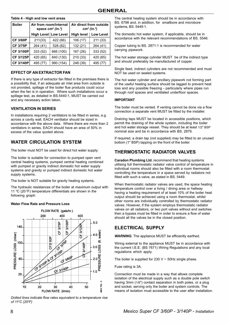
Water Flow Rate and Pressure Loss
Boiler Air from room/internal Air direct from outsidespace cm2 (in.2) cm2 (in.2)
High Level Low Level High level Low LevelCF 3/60P 211(33) 422 (66) 106 (17) 211 (33)CF 3/75P 264 (41) 528 (82) 132 (21) 264 (41)CF 3/100P 333 (52) 666 (100) 167 (26) 333 (52)CF 3/125P 420 (65) 840 (130) 210 (33) 420 (65)CF 3/140P 495 (77) 990 (154) 248 (39) 495 (77)
Table 4 - High and low vent areas
EFFECT OF AN EXTRACTOR FANIf there is any type of extractor fan fitted in the premises there isa possibility that, if an adequate air inlet area from outside isnot provided, spillage of the boiler flue products could occurwhen the fan is in operation. Where such installations occur aspillage test, as detailed in BS.5440:1, MUST be carried outand any necessary action taken.
VENTILATION IN SERIESIn installations requiring 2 ventilators to be fitted in series, e.g.across a cavity wall, EACH ventilator should be sized inaccordance with the above data. Where there are more than 2ventilators in series, EACH should have an area of 50% inexcess of the value quoted above.
WATER CIRCULATION SYSTEMThe boiler must NOT be used for direct hot water supply.
The boiler is suitable for connection to pumped open ventcentral heating systems, pumped central heating combinedwith pumped or gravity indirect domestic hot water supplysystems and gravity or pumped indirect domestic hot watersupply systems.
The boiler is NOT suitable for gravity heating systems.
The hydraulic resistances of the boiler at maximum output with11 0C (20 0F) temperature differentials are shown in thefollowing graph:
Dotted lines indicate flow rates equivalent to a temperature riseof 110C (200F)
The central heating system should be in accordance withBS. 6798 and, in addition, for smallbore and microboresystems, BS. 5449:1.
The domestic hot water system, if applicable, should be inaccordance with the relevant recommendations of BS. 5546.
Copper tubing to BS. 2871:1 is recommended for watercarrying pipework.
The hot water storage cylinder MUST be of the indirect typeand should preferably be manufactured of copper.
Single feed, indirect cylinders are not recommended and mustNOT be used on sealed systems.
The hot water cylinder and ancillary pipework not forming partof the useful heating surface should be lagged to prevent heatloss and any possible freezing - particularly where pipes runthrough roof spaces and ventilated underfloor spaces.
IMPORTANT
The boiler must be vented. If venting cannot be done via a flowconnection a separate vent MUST be fitted by the installer.
Draining taps MUST be located in accessible positions, whichpermit the draining of the whole system, including the boilerand hot water storage vessel. They should be at least 1/2" BSPnominal size and be in accordance with BS. 2879.
If required, a drain tap (not supplied) may be fitted to an unusedbottom (1" BSP) tapping on the front of the boiler.
THERMOSTATIC RADIATOR VALVESCaradon Plumbing Ltd. recommend that heating systemsutilising full thermostatic radiator valve control of temperature inindividual rooms should also be fitted with a room thermostatcontrolling the temperature in a space served by radiators notfitted with such a valve, as stated in BS. 5449.
When thermostatic radiator valves are used, the space heatingtemperature control over a living / dining area or hallwayhaving a heating requirement of at least 10% of the boiler heatoutput should be achieved using a room thermostat, whilstother rooms are individually controlled by thermostatic radiatorvalves. However, if the system employs thermostatic radiatorvalves on all radiators, or two port valves without end switchesthen a bypass must be fitted in order to ensure a flow of watershould all the valves be in the closed position.
ELECTRICAL SUPPLYWARNING. The appliance MUST be efficiently earthed.
Wiring external to the appliance MUST be in accordance withthe current I.E.E. (BS 7671) Wiring Regulations and any localregulations which apply.
The boiler is supplied for 230 V ~ 50Hz single phase.
Fuse rating is 3A.
Connection must be made in a way that allows completeisolation of the electrical supply such as a double pole switchhaving 3mm (1/8") contact separation in both poles, or a plugand socket, serving only the boiler and system controls. Themeans of isolation must accessible to the user after installation.
9Mexico Super CF 3/60P - 3/140P - Installation
INSTALLATION
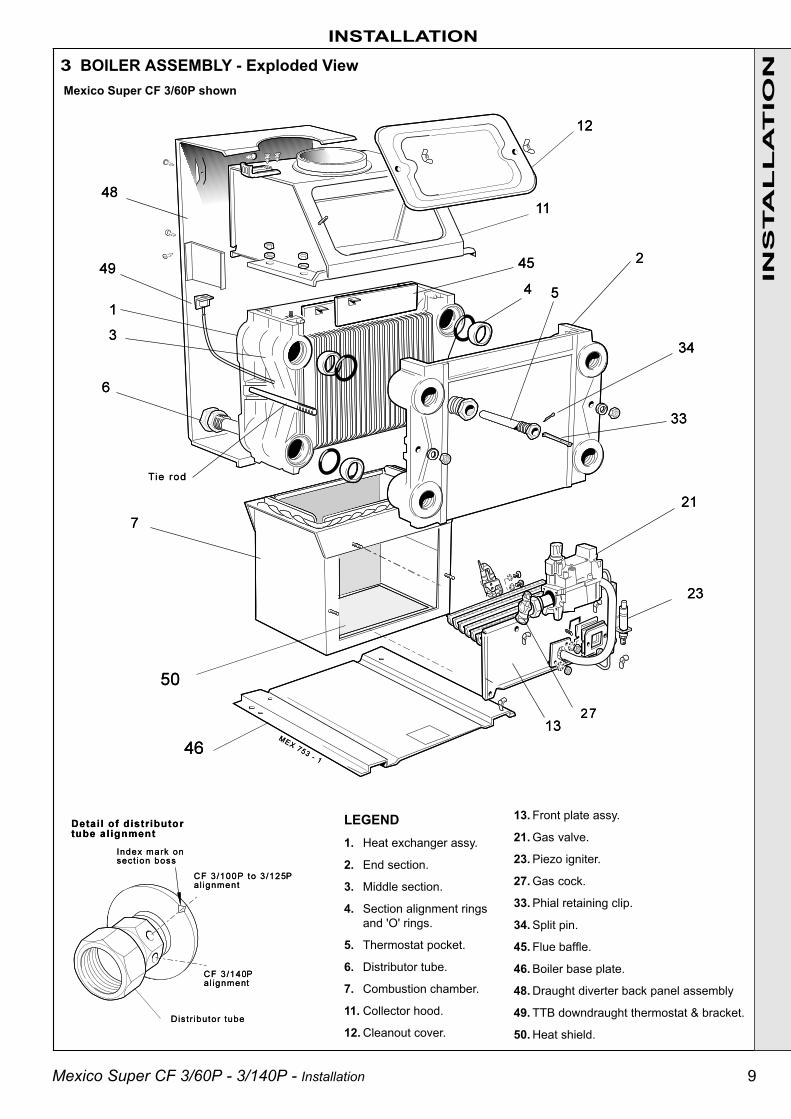
3 BOILER ASSEMBLY - Exploded View
LEGEND1. Heat exchanger assy.
2. End section.
3. Middle section.
4. Section alignment ringsand 'O' rings.
5. Thermostat pocket.
6. Distributor tube.
7. Combustion chamber.
11. Collector hood.
12. Cleanout cover.
Mexico Super CF 3/60P shown
13. Front plate assy.
21. Gas valve.
23. Piezo igniter.
27. Gas cock.
33. Phial retaining clip.
34. Split pin.
45. Flue baffle.
46. Boiler base plate.
48. Draught diverter back panel assembly
49. TTB downdraught thermostat & bracket.
50. Heat shield.
INS
TA
LL
AT
ION
10 Mexico Super CF 3/60P - 3/140P - Installation
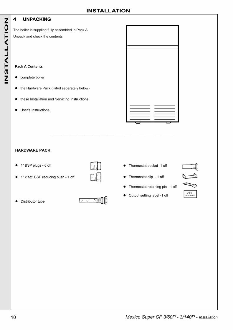
Pack A Contents
complete boiler
the Hardware Pack (listed separately below)
these Installation and Servicing Instructions
User's Instructions.
INSTALLATIONIN
STA
LL
AT
ION
The boiler is supplied fully assembled in Pack A.
Unpack and check the contents.
4 UNPACKING
HARDWARE PACK
1" BSP plugs - 6 off
1" x 1/2" BSP reducing bush - 1 off
Distributor tube
Thermostat pocket -1 off
Thermostat clip - 1 off
Thermostat retaining pin - 1 off
Output setting label -1 off

11Mexico Super CF 3/60P - 3/140P - Installation
5 BOILER CASING REMOVAL
INSTALLATION
INS
TA
LL
AT
ION
To install the boiler the casing MUST be removed.
6 CHECKING THE FLUEWAY BAFFLES
1. Lift off the lower front panel.
2. Remove 2 screws and lift off grille assembly.
3. Remove the gas valve cover by removing the retainingscrew. Disconnect the electrical leads.
4. Release the gas valve lead from the retaining clip.
5. Remove the 2 screws securing the control panel anddisengage the panel by lowering and pulling it forward.
6. Remove the 2 screws securing the top panel tothe side.
7. Draw the top panel forward and lift it off the boiler.
8. Remove the 2 screws securing LH side panel tothe flue collector and baseplate.
9. Pull the panel forward, lifting it clear of thelocating peg and remove.
10. Repeat steps 7 and 8 to remove the RH panel.
11. The boiler is held to the packaging base by 4 M6hex head screws. Remove the front screws,slacken the rear screws and remove the boilerfrom the packaging base.
1. Remove the flue cleanout cover.
2. CF 3/75P, CF 3/100P & CF 3/140P only. Ensure that thebaffles are fully inserted in the flueways.

12 Mexico Super CF 3/60P - 3/140P - Installation
Boiler size Dim. A
CF 3/60P & 3/75P 410 (16 1/8")
CF 3/100P 483 (19")
CF 3/125P 553 (21 3/8")
CF 3/140P 702 (27 5/8")
Table 6 - Gravity Domestic Hot Water & Pumped Central Heating
Connections - as viewed at front Thermostat Position
Back Section Front Section
CH DHW
Flow Return Flow Return Top
LH LH RH RH LH
LH RH RH LH LH
RH RH LH LH RH
RH LH LH RH RH
CF 3/140P ONLY
LH LH RH RH LH
RH RH LH LH RH
Table 5 - Fully Pumped Systems
Connections - as viewed at front Thermostat position
Back Section Front Section
Flow Return Top
LH LH LH
LH RH LH
RH RH RH
RH LH RH
CF 3/140P ONLY
LH LH LH
RH RH RH
INSTALLATION
7 PREPARING THE BOILERNotes.
Before placing the boiler in the selected position anygas and water connections at the rear of the boilershould be prepared, due to the possible lack ofaccess.
If an optional Pump Kit is to be used then it must befitted at this stage. Refer to separate fittinginstructions included with the kit.
1. Screw the distributor tube (supplied with a 1" BSP x28mm copper adaptor) into the selected heatingreturn tapping, using an appropriate jointingmaterial.
It is IMPERATIVE that the INDEX MARK on thedistributor bush is in alignment with the mark onthe section boss, as shown in Frame 3.
DO NOT disturb it when connecting subsequentpipework.
Fully pumped systems using more than 1 pump,serving separate zones, must have a commonreturn connection to the distributor tube.
2. Select the desired pumped flow tapping.
3. Screw the supplied boiler thermostat pocket into theappropriate front section tapping, using an approvedjointing material. Refer to Tables 5 and 6.
4. Connect pipe fittings to the rear tappings and plugany unused tappings. Note. If using iron elbows fit ashort straight connector into the boiler tapping first,to clear the casing when fitted.
5. Place the boiler in position. Note. The pump may befitted on the FLOW or RETURN.
INS
TA
LL
AT
ION
8 GAS CONNECTION1. A MINIMUM working gas pressure of 37 mbar
(14.8 in.w.g.) MUST be available at the boilerinlet, with the boiler operating.
2. Extend a gas supply pipe to the boiler (for sizerefer to Table 1 on page 3) and connect to thegas cock situated at the front LH side of theboiler.
3. Test the gas installation for soundness andpurge in accordance with BS.6891: 1988. Referto Frame 22 , item B.
13Mexico Super CF 3/60P - 3/140P - Installation
INS
TA
LL
AT
ION
INSTALLATION
9 WATER CONNECTION
1. Connect the system flow and return pipework to theboiler as appropriate. Refer to Frames 10 and 11 forguidance on system design.
Connection sizesAll water connections are RC 1 (1" BSP) but pumpedpipework must be increased to:CF 3/125P only 35 mm (1 1/4" BSP)CF 3/140P only 42mm (1 1/2" BSP)immediately after leaving the boiler.
Gravity pipework and connections must be at least:CF 3/100P & 3/125P only 28 mm (1" BSP)CF 3/140P only 35mm (1 1/2" BSP)
2. Ensure that all valves are open. Fill and vent the systemand check for water soundness.Notes.a. Isolating valves must be fitted as close to the pump as
possible.b. The boiler is not suitable for use with a direct hot water
cylinder or a sealed system.
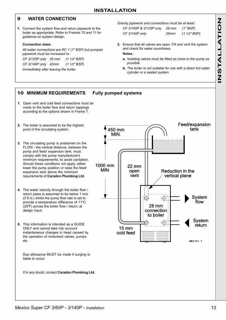
10 MINIMUM REQUIREMENTS Fully pumped systems
1. Open vent and cold feed connections must bemade to the boiler flow and return tappingsaccording to the options shown in Frame 7.
2. The boiler is assumed to be the highestpoint of the circulating system.
3. The circulating pump is positioned on theFLOW - the vertical distance, between thepump and feed/ expansion tank, mustcomply with the pump manufacturer'sminimum requirements, to avoid cavitation.Should these conditions not apply, eitherlower the pump position or raise the feed/expansion tank above the minimumrequirements of Caradon Plumbing Ltd.
4. The water velocity through the boiler flow /return pipes is assumed to be below 1 m/s(3 ft./s.) whilst the pump flow rate is set toprovide a temperature difference of 110C(200F) across the boiler flow / return, atdesign input.
5. This information is intended as a GUlDEONLY and cannot take into accountinstantaneous changes in head caused bythe operation of motorised valves, pumpsetc.
Due allowance MUST be made if surging isliable to occur.
If in any doubt, contact Caradon Plumbing Ltd.

14 Mexico Super CF 3/60P - 3/140P - Installation
11 GRAVITY HOT WATER & PUMPED CENTRAL HEATING
INS
TA
LL
AT
ION
INSTALLATION
12 FLUE CONNECTIONConnect the flue pipe to the flue outlet.
The flue pipe spigot and socket connections should be sealedwith fibreglass rope, or similar, and suitable fireclay cement.
Notes.
a. The boiler flue connection outlet size is suitable for flue pipeconforming to BS 567.
If sheet steel flue pipe is fitted, a suitable adaptor must beused.
b. To facilitate installation and subsequent disconnection it isrecommended that a slip or split socket be included in theflue installation, adjacent to the boiler flue outlet connection.
c. A minimum of 600mm (2') of vertical flue directly above theboiler should be provided.
1. Separate flow and return connections are used foreach service. All possible configurations are given inFrame 7 and ONLY those shown should be used.
2. The schematic pipework graph is based on theassumption that NO MORE than 8 elbows are used inthe gravity loop, including entry to the boiler.
3. For each extra elbow in excess of 8, (R) MUST bereduced by 300 mm (12") or (H) increased by 100 mm(4")
4. Whatever value is selected for (R), the value of (H)MUST be at least that indicated by the graph
(R) = the horizontal distance between the centre line ofthe cylinder and the boiler tappings used -measured along the pipe run
(H) = the vertical distance between the top of the boilerand the base of the cylinder
Notes.
a. Flow and return pipes should rise vertically onleaving the boiler.
b. Horizontal pipes should be ABOVE ceilinglevel and as short as possible.
c. A MINIMUM inclination of 25 mm per 3 m run(1" per 10') is required to avoid air locks.
If the above conditions cannot be met thenpumped primaries should be used.
15Mexico Super CF 3/60P - 3/140P - Installation
13 ELECTRICAL CONNECTIONS
INSTALLATION
INS
TA
LL
AT
ION
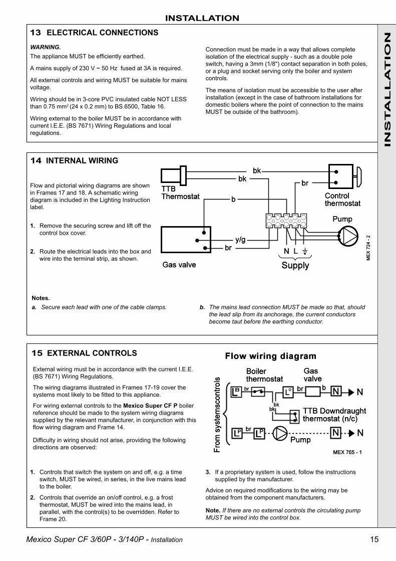
14 INTERNAL WIRING
15 EXTERNAL CONTROLS
External wiring must be in accordance with the current I.E.E.(BS 7671) Wiring Regulations.
The wiring diagrams illustrated in Frames 17-19 cover thesystems most likely to be fitted to this appliance.
For wiring external controls to the Mexico Super CF P boilerreference should be made to the system wiring diagramssupplied by the relevant manufacturer, in conjunction with thisflow wiring diagram and Frame 14.
Difficulty in wiring should not arise, providing the followingdirections are observed:
3. If a proprietary system is used, follow the instructionssupplied by the manufacturer.
Advice on required modifications to the wiring may beobtained from the component manufacturers.
Note. If there are no external controls the circulating pumpMUST be wired into the control box.
1. Controls that switch the system on and off, e.g. a timeswitch, MUST be wired, in series, in the live mains leadto the boiler.
2. Controls that override an on/off control, e.g. a frostthermostat, MUST be wired into the mains lead, inparallel, with the control(s) to be overridden. Refer toFrame 20.
WARNING.The appliance MUST be efficiently earthed.
A mains supply of 230 V ~ 50 Hz fused at 3A is required.
All external controls and wiring MUST be suitable for mainsvoltage.
Wiring should be in 3-core PVC insulated cable NOT LESSthan 0.75 mm2 (24 x 0.2 mm) to BS.6500, Table 16.
Wiring external to the boiler MUST be in accordance withcurrent l.E.E. (BS 7671) Wiring Regulations and localregulations.
Connection must be made in a way that allows completeisolation of the electrical supply - such as a double poleswitch, having a 3mm (1/8") contact separation in both poles,or a plug and socket serving only the boiler and systemcontrols.
The means of isolation must be accessible to the user afterinstallation (except in the case of bathroom installations fordomestic boilers where the point of connection to the mainsMUST be outside of the bathroom).
Flow and pictorial wiring diagrams are shownin Frames 17 and 18. A schematic wiringdiagram is included in the Lighting Instructionlabel.
1. Remove the securing screw and lift off thecontrol box cover.
2. Route the electrical leads into the box andwire into the terminal strip, as shown.
Notes.a. Secure each lead with one of the cable clamps. b. The mains lead connection MUST be made so that, should
the lead slip from its anchorage, the current conductorsbecome taut before the earthing conductor.
16 Mexico Super CF 3/60P - 3/140P - Installation
INSTALLATIONIN
STA
LL
AT
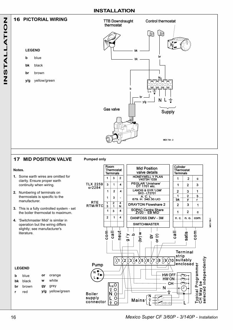
ION 16 PICTORIAL WIRING
LEGEND
b blue
bk black
br brown
y/g yellow/green
or orangew whitegy greyy/g yellow/green
LEGEND
b bluebk blackbr brownr red
17 MID POSITION VALVE Pumped only
Notes.
1. Some earth wires are omitted forclarity. Ensure proper earthcontinuity when wiring.
2. Numbering of terminals onthermostats is specific to themanufacturer.
3. This is a fully controlled system - setthe boiler thermostat to maximum.
4. 'Switchmaster Midi' is similar inoperation but the wiring differsslightly; see manufacturer'sliterature.
17Mexico Super CF 3/60P - 3/140P - Installation
INS
TA
LL
AT
ION
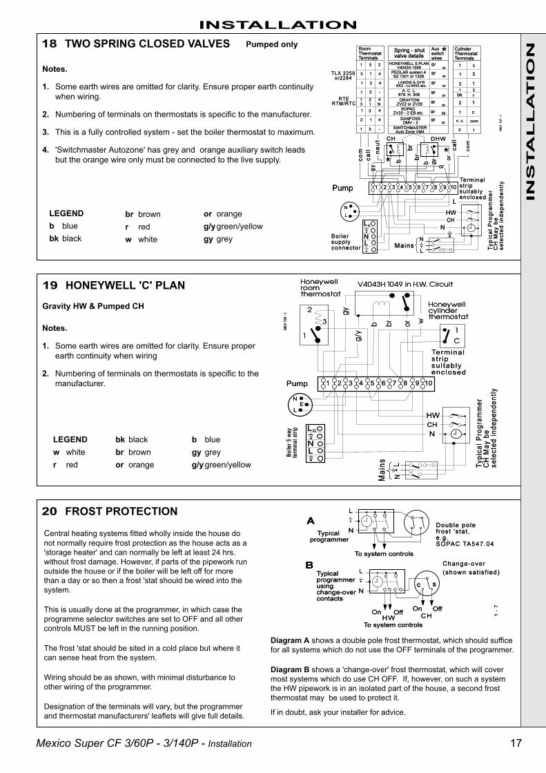
INSTALLATION18 TWO SPRING CLOSED VALVES
Notes.
1. Some earth wires are omitted for clarity. Ensure proper earth continuitywhen wiring.
2. Numbering of terminals on thermostats is specific to the manufacturer.
3. This is a fully controlled system - set the boiler thermostat to maximum.
4. 'Switchmaster Autozone' has grey and orange auxiliary switch leadsbut the orange wire only must be connected to the live supply.
LEGENDb bluebk black
Pumped only
19 HONEYWELL 'C' PLAN
Notes.
1. Some earth wires are omitted for clarity. Ensure properearth continuity when wiring
2. Numbering of terminals on thermostats is specific to themanufacturer.
LEGENDw whiter red
bk blackbr brownor orange
b bluegy greyg/ygreen/yellow
20 FROST PROTECTION
br brownr redw white
or orangeg/ygreen/yellowgy grey
Diagram A shows a double pole frost thermostat, which should sufficefor all systems which do not use the OFF terminals of the programmer.
Diagram B shows a 'change-over' frost thermostat, which will covermost systems which do use CH OFF. If, however, on such a systemthe HW pipework is in an isolated part of the house, a second frostthermostat may be used to protect it.
If in doubt, ask your installer for advice.
Central heating systems fitted wholly inside the house donot normally require frost protection as the house acts as a'storage heater' and can normally be left at least 24 hrs.without frost damage. However, if parts of the pipework runoutside the house or if the boiler will be left off for morethan a day or so then a frost 'stat should be wired into thesystem.
This is usually done at the programmer, in which case theprogramme selector switches are set to OFF and all othercontrols MUST be left in the running position.
The frost 'stat should be sited in a cold place but where itcan sense heat from the system.
Wiring should be as shown, with minimal disturbance toother wiring of the programmer.
Designation of the terminals will vary, but the programmerand thermostat manufacturers' leaflets will give full details.
Gravity HW & Pumped CH

18 Mexico Super CF 3/60P - 3/140P - Installation
INS
TA
LL
AT
ION
WARNING. Whilst effecting the required gas soundness test and purging air from the gas installation,open all windows and doors, extinguish naked lights and DO NOT SMOKE.
INSTALLATION
21 FITTING THE CASING
22 COMMISSIONING AND TESTING
A. ELECTRICAL INSTALLATION
1. Checks to ensure electrical safety should be carriedout by a competent person.
2. ALWAYS carry out preliminary electrical systemchecks, i.e. earth continuity, polarity, resistance toearth and short circuit using a suitable test meter.
B. GAS INSTALLATION1. The whole of the gas installation, including the meter,
MUST be inspected and tested for soundness, andpurged in accordance with the recommendations ofBS. 6891.
2. Purging air from the gas installation may be expedited byloosening the union on the gas service cock on the boilerand purging until gas is detected.
3. Retighten the union and check for gas soundness.
1. Offer up the RH side panel, locating it with thepeg in the baseplate, and push the panel back.
2. Secure the panel to the baseplate and collectorhood.
3. Repeat steps 1 and 2 to refit the LH side panel.
4. Place the top panel and push back.
5. Secure the top panel to the side panels.
IMPORTANT. Wiring within the boiler casing mustbe neartly secured with the cable strapsprovided and MUST NOT be allowed to touchthe burner front plate, or the cleanout cover andthe collector hood.
6. Replace the control box cover and refit thecontrol panel using the screws previouslyremoved.
7. Insert the thermostat phial and phial retainingclip into the thermostat pocket. Take care notto kink the thermostat capillary as it isunwound andsecure it with the split pin asshown.
8. Refit the grille assembly

19Mexico Super CF 3/60P - 3/140P - Installation
INS
TA
LL
AT
ION
INSTALLATION23 INITIAL LIGHTING
24 PILOT BURNER CONNECTION GAS SOUNDNESS1. Turn the gas service cock to OFF and undo the union nut.
2. Remove the 4 wing nuts and withdraw the burner and controlsassembly, complete, from the boiler.
3. Invert the burner assembly and reconnect to the gas service cock.
4. Turn the gas service cock to ON.
5. Light the pilot burner. Refer to Frame 23.
6. Test for gas soundness around the pilot burner connection, usingleak detection fluid.
7. Turn the gas service cock to OFF and return the burner andcontrols assembly to the normal working position.
1. Connect the gas valve electrical leads and refit the cover.
2. Check that the gas service cock (E) is ON and that theboiler thermostat control knob (H) is OFF.
3. Loosen the screw in the burner pressure test point (B) andconnect a gas pressure gauge via a flexible tube.
4. Turn the gas control knob (A) CLOCKWISE until resistanceis felt and then release it..
5. Push in and retain fully depressed the gas control knob (A).Press and release the piezo unit button (G) repeatedly untilthe pilot is seen to light through the sightglass (F).
6. Hold the gas control knob (A) depressed for 15 secondsafter the pilot burner has ignited, then release.
If the pilot burner fails to remain alight at this stage, repeatthe procedure detailed above but wait longer than 15seconds before releasing the gas control knob (A).
7. Check the appearance of the pilot flame to ensure that itenvelops the tip of the thermocouple and is approximately
25mm (1") long. The pilot flame is factory set and noadjustment is possible.
8. Switch the boiler thermostat control knob (H ) to position 6and check that the burner cross-lights smoothly from thepilot flame.Note. The pilot burner connection can be tested for gassoundness. Refer to Frame 24.
9. Test for gas soundness around the boiler gas componentjoints, using leak detection fluid.
10. Operate the boiler for 10 minutes to stabilise the burnertemperature. The boiler is pre-set at the factory to itsmaximum nominal rating.
11. Immediately check that there is no spillage of combustionproducts from the draught diverter outlets by carrying out aspillage test as detailed in BS.5440:1.Note. This must be done before any building in.
12. Turn the boiler thermostat knob (H) to OFF.
13. Remove the pressure gauge and tube. Retighten thescrew in the pressure test point, ensuring that a gas-tightseal is made.
Boiler controls
LEGENDA Gas control knobB Burner pressure test pointC Main burner pressure adjusterD Inlet pressure test pointE Gas service cockF SightglassG Piezo ignition buttonH Boiler thermostat knobJ Overheat thermostat (optional)
reset button
CF 3/60P shown
20 Mexico Super CF 3/60P - 3/140P - Installation
INS
TA
LL
AT
ION 25 GENERAL CHECKS
Make the following checks for correct operation:
1. Turn the boiler thermostat OFF and ON to check that themain burner is extinguished and relit in response.
2. Check that the programmer, if fitted, and all other systemcontrols function correctly.
Operate each control separately and check that the mainburner or circulating pump (as the case may be) responds.
3. Flame failure device
Check the operation of the flame failure device in the gascontrol valve as follows:
a. Extinguish the pilot flame by closing the gas servicecock and note the time taken for the flame failuredevice to shut down - identified by a click within the gascontrol valve. This must not be longer than 60 seconds.
b. Open the gas service cock and relight the pilot.
c. Turner the boiler thermostat ON. The burner shouldlight.
d. Turn the gas control knob to the OFF position - refer toFrame 23. The main burner and pilot flame should shutdown immediately. Note. A latch in the gas controlvalve provides a safety delay period of approximately30 seconds before the pilot can be relit.
4. Water circulation System
a. With the system HOT, examine all water connections forsoundness.
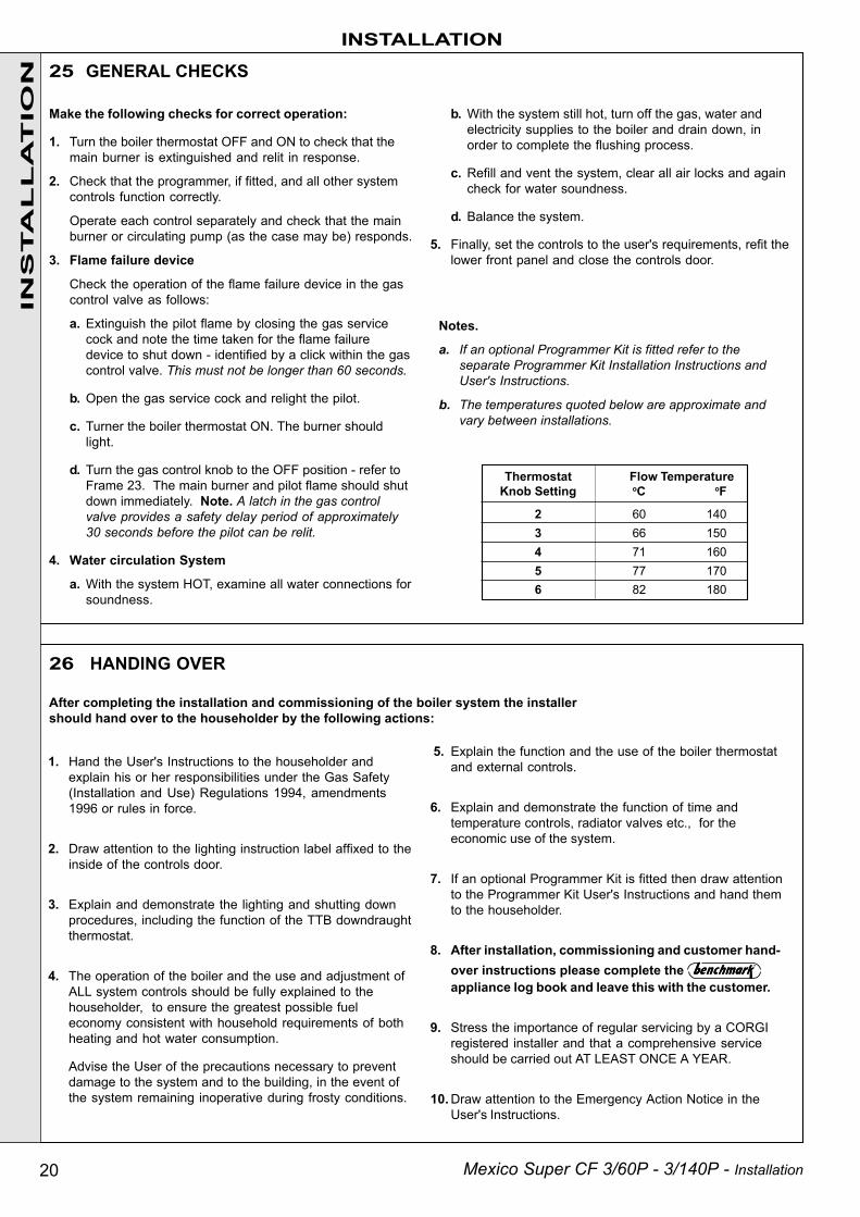
Thermostat Flow TemperatureKnob Setting oC oF
2 60 1403 66 1504 71 1605 77 1706 82 180
1. Hand the User's Instructions to the householder andexplain his or her responsibilities under the Gas Safety(Installation and Use) Regulations 1994, amendments1996 or rules in force.
2. Draw attention to the lighting instruction label affixed to theinside of the controls door.
3. Explain and demonstrate the lighting and shutting downprocedures, including the function of the TTB downdraughtthermostat.
4. The operation of the boiler and the use and adjustment ofALL system controls should be fully explained to thehouseholder, to ensure the greatest possible fueleconomy consistent with household requirements of bothheating and hot water consumption.
Advise the User of the precautions necessary to preventdamage to the system and to the building, in the event ofthe system remaining inoperative during frosty conditions.
b. With the system still hot, turn off the gas, water andelectricity supplies to the boiler and drain down, inorder to complete the flushing process.
c. Refill and vent the system, clear all air locks and againcheck for water soundness.
d. Balance the system.
5. Finally, set the controls to the user's requirements, refit thelower front panel and close the controls door.
Notes.
a. If an optional Programmer Kit is fitted refer to theseparate Programmer Kit Installation Instructions andUser's Instructions.
b. The temperatures quoted below are approximate andvary between installations.
26 HANDING OVER
After completing the installation and commissioning of the boiler system the installershould hand over to the householder by the following actions:
5. Explain the function and the use of the boiler thermostatand external controls.
6. Explain and demonstrate the function of time andtemperature controls, radiator valves etc., for theeconomic use of the system.
7. If an optional Programmer Kit is fitted then draw attentionto the Programmer Kit User's Instructions and hand themto the householder.
8. After installation, commissioning and customer hand-over instructions please complete the appliance log book and leave this with the customer.
9. Stress the importance of regular servicing by a CORGIregistered installer and that a comprehensive serviceshould be carried out AT LEAST ONCE A YEAR.
10. Draw attention to the Emergency Action Notice in theUser's Instructions.
INSTALLATION
21Mexico Super CF 3/60P - 3/140P - Installation
27 SCHEDULESERVICING
SE
RV
ICIN
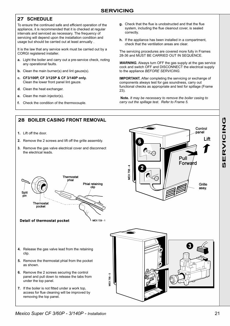
G28 BOILER CASING FRONT REMOVAL
1. Lift off the door.
2. Remove the 2 screws and lift off the grille assembly.
3. Remove the gas valve electrical cover and disconnectthe electrical leads.
4. Release the gas valve lead from the retainingclip.
5. Remove the thermostat phial from the pocketas shown.
6. Remove the 2 screws securing the controlpanel and pull down to release the tabs fromunder the top panel.
7. If the boiler is not fitted under a work top,access for flue cleaning will be improved byremoving the top panel.
To ensure the continued safe and efficient operation of theappliance, it is recommended that it is checked at regularintervals and serviced as necessary. The frequency ofservicing will depend upon the installation condition andusage but should be carried out at least annually .
It is the law that any service work must be carried out by aCORGI registered installer.
a. Light the boiler and carry out a pre-service check, notingany operational faults.
b. Clean the main burner(s) and lint gauze(s).
c. CF3/100P, CF 3/125P & CF 3/140P only.Clean the lower front panel lint gauze.
d. Clean the heat exchanger.
e. Clean the main injector(s).
f. Check the condition of the thermocouple.
g. Check that the flue is unobstructed and that the fluesystem, including the flue cleanout cover, is sealedcorrectly.
h. If the appliance has been installed in a compartment,check that the ventilation areas are clear.
The servicing procedures are covered more fully in Frames28-36 and MUST BE CARRIED OUT IN SEQUENCE.
WARNING. Always turn OFF the gas supply at the gas servicecock and switch OFF and DISCONNECT the electrical supplyto the appliance BEFORE SERVICING.
IMPORTANT. After completing the servicing or exchange ofcomponents always test for gas soundness, carry outfunctional checks as appropriate and test for spillage (Frame23).
Note. It may be necessary to remove the boiler casing tocarry out the spillage test. Refer to Frame 5.
22 Mexico Super CF 3/60P - 3/140P - Installation
SERVICING
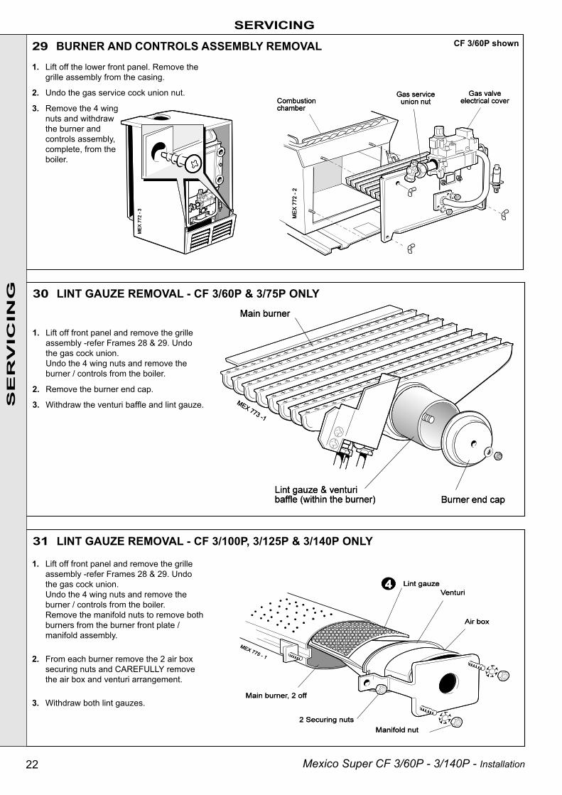
29 BURNER AND CONTROLS ASSEMBLY REMOVAL
SE
RV
ICIN
G 30 LINT GAUZE REMOVAL - CF 3/60P & 3/75P ONLY
1. Lift off front panel and remove the grilleassembly -refer Frames 28 & 29. Undothe gas cock union.Undo the 4 wing nuts and remove theburner / controls from the boiler.
2. Remove the burner end cap.
3. Withdraw the venturi baffle and lint gauze.
CF 3/60P shown
1. Lift off front panel and remove the grilleassembly -refer Frames 28 & 29. Undothe gas cock union.Undo the 4 wing nuts and remove theburner / controls from the boiler.Remove the manifold nuts to remove bothburners from the burner front plate /manifold assembly.
2. From each burner remove the 2 air boxsecuring nuts and CAREFULLY removethe air box and venturi arrangement.
3. Withdraw both lint gauzes.
31 LINT GAUZE REMOVAL - CF 3/100P, 3/125P & 3/140P ONLY
1. Lift off the lower front panel. Remove thegrille assembly from the casing.
2. Undo the gas service cock union nut.
3. Remove the 4 wingnuts and withdrawthe burner andcontrols assembly,complete, from theboiler.

23Mexico Super CF 3/60P - 3/140P - Installation
32 CLEANING THE BURNER ASSEMBLY
SE
RV
ICIN
G
SERVICING
5. Inspect the pilot burner, thermocouple and ignition electrode- ensure that they are clear and in good condition. Check that:
a. The pilot burner is clean and unobstructed.
b. The ignition electrode is clean and undamaged.
c. The ignition lead is in good condition and securelyconnected.
d. The ignition gap is correct. Refer to Frames 46 & 47.
e. The thermocouple tip is not burned or cracked.
f. The position of the thermocouple relative to the pilotburner is correct. Refer to Frames 46 & 47.
g. The thermocouple terminal at the gas valve is clean.
6. Clean or renew components as necessary.
1. Clean the lint gauze(s) to remove any deposits of lint, fluffetc.
2. Brush off any deposits that may have fallen on to the burnerhead, ensuring that the flame ports are unobstructed, andremove any debris that may have collected.
Note. Brushes with metallic bristles MUST NOT be used.
3. Remove the main burner injector(s). Check, clean or replace,as required.
4. Refit the injector(s), using an approved jointing compound.
33 CLEANING THE LOWER FRONT PANEL LINT ARRESTING GAUZE- CF 3/100P, 3/125P & CF 3/140P ONLY
1. Unclip the gauze from the grille assembly and liftit clear of the bottom return edge.
2. Clean the gauze to remove any deposits of lint orfluff.
3. Refit the gauze by entering the bottom edgebehind the grille return edge and engaging thetop in the clips.

24 Mexico Super CF 3/60P - 3/140P - Installation
SERVICING
34 CLEANING THE FLUEWAYS
1. Remove the 2 wing nuts and lift offthe cleanout cover.
2. CF 3/75P, CF 3/100P & CF 3/140Ponly.Lift out the flue baffles.
3. Remove all loose deposits from theheat exchanger, especially frombetween the fins, using a suitablebrush. Remove all debris from thecombustion chamber base.
4. Check that the flue outlet duct isunobstructed.
SE
RV
ICIN
G
3. Refit the lower front panel
NB. The burner pressure is not adjustable. If the burnerpressure is incorrect check the supply pressure and allisolating valves ,and contact your LPG service centre, ifnecessary.
1. Pilot Pressure
Pilot adjustment is factory set to maximum and noadjustment is possible.
2. Main Burner Pressure
After servicing, reference should be made to Table 1, page3, which quotes details of the rated output with the relatedburner pressure and heat input.
36 GAS PRESSURE ADJUSTMENT
retaining clip are correctly located in the thermostatpocket and secured by the split pin. Refer to Frame 28.
5. Check the sightglass in the front plate. Clean or renew asnecessary.
6. Renew any damaged or deteriorating front plate gasket.
7. Refit the burner and controls assembly.
8. Reconnect the gas service cock.
9. Refit the grille assembly.
Re-assemble the boiler in the following order :
1. Refit the flue baffles into the boiler flueways, ensuringthat they are correctly repositioned. Refer to Frame 6.
2. Refit the flue cleanout cover, renewing any damaged ordeteriorating sealing gasket.
3. Refit the casing top panel.
4. Reconnect the electrical wiring and refit the controlspanel, ensuring that the thermostat phial and phial
35 RE-ASSEMBLY
25Mexico Super CF 3/60P - 3/140P - Installation
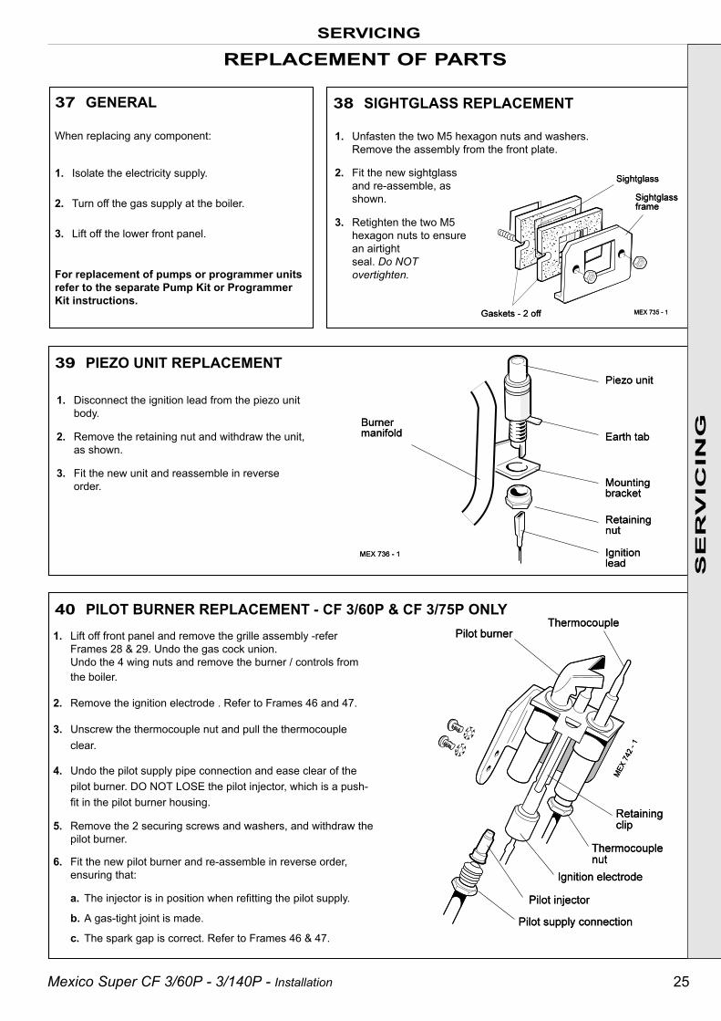
1. Disconnect the ignition lead from the piezo unitbody.
2. Remove the retaining nut and withdraw the unit,as shown.
3. Fit the new unit and reassemble in reverseorder.
SERVICING
39 PIEZO UNIT REPLACEMENT
40 PILOT BURNER REPLACEMENT - CF 3/60P & CF 3/75P ONLY1. Lift off front panel and remove the grille assembly -refer
Frames 28 & 29. Undo the gas cock union.Undo the 4 wing nuts and remove the burner / controls fromthe boiler.
2. Remove the ignition electrode . Refer to Frames 46 and 47.
3. Unscrew the thermocouple nut and pull the thermocoupleclear.
4. Undo the pilot supply pipe connection and ease clear of thepilot burner. DO NOT LOSE the pilot injector, which is a push-fit in the pilot burner housing.
5. Remove the 2 securing screws and washers, and withdraw thepilot burner.
6. Fit the new pilot burner and re-assemble in reverse order,ensuring that:
a. The injector is in position when refitting the pilot supply.
b. A gas-tight joint is made.
c. The spark gap is correct. Refer to Frames 46 & 47.
REPLACEMENT OF PARTS
SE
RV
ICIN
G
37 GENERAL
1. Unfasten the two M5 hexagon nuts and washers.Remove the assembly from the front plate.
2. Fit the new sightglassand re-assemble, asshown.
3. Retighten the two M5hexagon nuts to ensurean airtightseal. Do NOTovertighten.
38 SIGHTGLASS REPLACEMENT
When replacing any component:
1. Isolate the electricity supply.
2. Turn off the gas supply at the boiler.
3. Lift off the lower front panel.
For replacement of pumps or programmer unitsrefer to the separate Pump Kit or ProgrammerKit instructions.
26 Mexico Super CF 3/60P - 3/140P - Installation
SERVICING
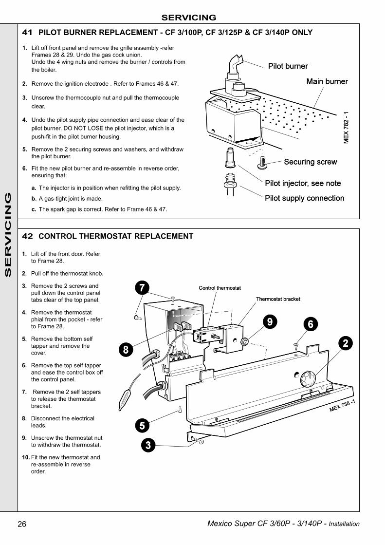
41 PILOT BURNER REPLACEMENT - CF 3/100P, CF 3/125P & CF 3/140P ONLY
1. Lift off the front door. Referto Frame 28.
2. Pull off the thermostat knob.
3. Remove the 2 screws andpull down the control paneltabs clear of the top panel.
4. Remove the thermostatphial from the pocket - referto Frame 28.
5. Remove the bottom selftapper and remove thecover.
6. Remove the top self tapperand ease the control box offthe control panel.
7. Remove the 2 self tappersto release the thermostatbracket.
8. Disconnect the electricalleads.
9. Unscrew the thermostat nutto withdraw the thermostat.
10. Fit the new thermostat andre-assemble in reverseorder.
42 CONTROL THERMOSTAT REPLACEMENT
SE
RV
ICIN
G
1. Lift off front panel and remove the grille assembly -referFrames 28 & 29. Undo the gas cock union.Undo the 4 wing nuts and remove the burner / controls fromthe boiler.
2. Remove the ignition electrode . Refer to Frames 46 & 47.
3. Unscrew the thermocouple nut and pull the thermocoupleclear.
4. Undo the pilot supply pipe connection and ease clear of thepilot burner. DO NOT LOSE the pilot injector, which is apush-fit in the pilot burner housing.
5. Remove the 2 securing screws and washers, and withdrawthe pilot burner.
6. Fit the new pilot burner and re-assemble in reverse order,ensuring that:
a. The injector is in position when refitting the pilot supply.
b. A gas-tight joint is made.
c. The spark gap is correct. Refer to Frame 46 & 47.

27Mexico Super CF 3/60P - 3/140P - Installation
44 OVERHEAT THERMOSTAT REPLACEMENT (if fitted)
SERVICING
43 CONTROLS PANEL REPLACEMENT
1. Lift off front lower panel. Refer to Frame 28.
2. Slacken the screw at the thermostat pocket andwithdraw the phial from the pocket.
3. Remove the thermostat backnut.
4. Remove the 2 Eco leads.
5. Fit the new thermostat (lead polarity immaterial),ensuring that the alignment peg on the thermostatsits in the small hole adjacent to the main fixing hole,and reassemble in reverse order.
6. Replace the lower front panel.
7. Check the operation of the boiler.
1. Lift off the lower front panel. Refer to Frame 28
2. Pull off the thermostat knob.
3. Disconnect the electrical connections from thegas valve.
4. Unscrew the 2 screws and pull down thecontrol panel so that the 2 tabs clear the toppanel.
5. Remove the thermostat phial from the pocket.Refer to Frame 28.
6. Remove the bottom screw and remove thecover from the control box.
7. Remove the top screw and ease the controlbox off the control panel.
8. Disconnect the mains electrical supply fromthe terminal strip and release from its clamp.
9. Remove the 2 screws to release thethermostat bracket.
10. Disconnect the TTB thermostat leads from theterminal strip and control thermostat, thenrelease from its bush.
11. On the new control box gain access to the controlthermostat as described above.
12. Discard the control thermostat lead that connects toterminal strip marked 'LG'.
13. Reconnect the TTB thermostat lead to the controlthermostat and terminal strip marked 'LG'.
14. Assemble new control box and panel and fit to the casing,in reverse order.
SE
RV
ICIN
G

28 Mexico Super CF 3/60P - 3/140P - Installation
SERVICING
45 IGNITION LEAD REPLACEMENT
1. Lift off front panel and remove the grilleassembly - refer to Frames 28 & 29.
Undo the gas cock union.
Undo the 4 wing nuts and remove theburner / controls from the boiler.
2. Remove the purse clip.
3. Disconnect the ignition lead from the baseof the electrode and the piezo unit, andwithdraw the lead.
4. Fit the new lead and re-assemble in reverseorder.
46 IGNITION ELECTRODE REPLACEMENT - CF 3/60P & CF 3/75P ONLY
SE
RV
ICIN
G
Pilot burner assembly
Detail of pilot flame length and spark gap
1. Lift off front panel and remove the grille assembly -referFrames 28 & 29. Undo the gas cock union.Undo the 4 wing nuts and remove the burner / controlsfrom the boiler.
2. Disconnect the ignition lead.
3. Remove the electrode retaining nut and withdraw theelectrode.
4. Fit the new electrode and re-assemble in reverse order.

29Mexico Super CF 3/60P - 3/140P - Installation
SERVICING
47 IGNITION ELECTRODE REPLACEMENT - CF 3/100P, 3/125P & CF 3/140P ONLY
1. Lift off front panel and remove the grilleassembly -refer Frames 28 & 29. Undo thegas cock union.Undo the 4 wing nuts and remove the burner /controls from the boiler.
2. Disconnect the spark lead.
3. Remove the electrode retaining nut andwithdraw the electrode.
4. Fit the new electrode and re-assemble inreverse order.
Detail of pilot flame length and spark gap
Pilot burner assembly
48 THERMOCOUPLE REPLACEMENT - CF 3/60P & CF 3/75P ONLYS
ER
VIC
ING
1. Lift off front panel and remove the grille assembly -refer Frames 28 & 29. Undo the gas cock union.Undo the 4 wing nuts and remove the burner /controls from the boiler.
2. Remove the purse clip.
3. Undo the thermocouple connection at the pilotburner and pull the thermocouple clear.
4. Undo the thermocouple connection at the gas valveand withdraw the thermocouple.
5. Fit the new thermocouple and re-assemble inreverse order
Note. Avoid sharp bends in the thermocouple lead andensure that it follows the same route as previously.

30 Mexico Super CF 3/60P - 3/140P - Installation
49 THERMOCOUPLE REPLACEMENT - CF 3/100P, CF 3/125P & CF 3/140P ONLY
1. Lift off front panel and remove the grille assembly -referFrames 28 & 29. Undo the gas cock union.Undo the 4 wing nuts and remove the burner / controlsfrom the boiler.
2. Remove the purse clip.
3. Undo the thermocouple nut at the pilot burner and pull thethermocouple clear.
4. Undo the thermocouple connection at the gas valve andwithdraw the thermocouple.
5. Fit the new thermocouple and re-assemble in reverseorder
Note.Avoid sharp bends in the thermocouple lead and ensure that itfollows the same route as previously.
SERVICING
1. Lift off front panel and remove the grille assembly -referFrames 28 & 29. Undo the gas cock union.Undo the 4 wing nuts and remove the burner / controls fromthe boiler.
2. Remove the 2 screws securing the pilot burner and pull theassembly clear of the main burner.
3. Remove the 2 nuts and washers securing the burner tothe front plate and manifold. Withdraw the burner.
4. Fit the new burner and re-assemble in reverse order,taking care not to damage the main burner injector whichis screwed into the burner manifold.
50 MAIN BURNER REPLACEMENT - CF 3/60P & CF 3/75P ONLY
SE
RV
ICIN
G

31Mexico Super CF 3/60P - 3/140P - Installation
SERVICING
52 MAIN BURNER INJECTOR REPLACEMENT - CF 3/60P & CF 3/75P ONLY
51 MAIN BURNER REPLACEMENT - CF 3/100P, CF 3/125P & CF 3/140P ONLY4. Remove the 2 screws securing the pilot burner and pull
the assembly clear of the main burner.
5. Remove the 2 nuts and washers securing the burner(s) tothe front plate and manifold. Withdraw the burner.
6. Fit the new burner(s) and re-assemble in reverse order,taking care not to damage the main burner injector whichis screwed into the burner manifold.
1. Lift off front panel and remove the grille assembly -refer toFrames 28 & 29.
2. Undo the gas cock union.Undo the 4 wing nuts and remove the burner / controls fromthe boiler.
3. Remove the 2 nuts and washers securing the bottomburner baffle and remove the baffle.
SE
RV
ICIN
G
1. Lift off front panel and removethe grille assembly -refer Frames28 & 29. Undo the gas cockunion.Undo the 4 wing nuts andremove the burner / controlsfrom the boiler.
2. Remove the 2 screws securingthe pilot burner and pull theassembly clear of the mainburner.
3. Undo the 2 nuts and remove themanifold/controls from the frontplate.
4. Unscrew the burner injector fromthe manifold.
5. Fit the new injector, using anapproved jointing compound, andre-assemble in reverse order.
32 Mexico Super CF 3/60P - 3/140P - Installation
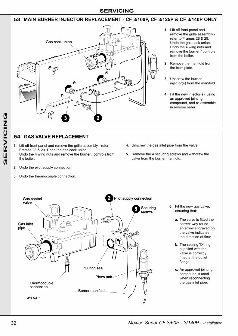
53 MAIN BURNER INJECTOR REPLACEMENT - CF 3/100P, CF 3/125P & CF 3/140P ONLYSERVICING
54 GAS VALVE REPLACEMENT
SE
RV
ICIN
G
1. Lift off front panel andremove the grille assembly -refer to Frames 28 & 29.Undo the gas cock union.Undo the 4 wing nuts andremove the burner / controlsfrom the boiler.
2. Remove the manifold fromthe front plate.
3. Unscrew the burnerinjector(s) from the manifold.
4. Fit the new injector(s), usingan approved jointingcompound, and re-assemblein reverse order.
1. Lift off front panel and remove the grille assembly - referFrames 28 & 29. Undo the gas cock union.Undo the 4 wing nuts and remove the burner / controls fromthe boiler.
2. Undo the pilot supply connection.
3. Undo the thermocouple connection.
4. Unscrew the gas inlet pipe from the valve.
5. Remove the 4 securing screws and withdraw thevalve from the burner manifold.
6. Fit the new gas valve,ensuring that:
a. The valve is fitted thecorrect way round -an arrow engraved onthe valve indicatesthe direction of flow.
b. The sealing 'O' ringsupplied with thevalve is correctlyfitted at the outletflange.
c. An approved jointingcompound is usedwhen reconnectingthe gas inlet pipe.

33Mexico Super CF 3/60P - 3/140P - Installation
SERVICING
SE
RV
ICIN
G
1. Remove the control panel. Refer to Frame 28.
2. Remove the securing screws and lift off the controlbox cover.
3. Disconnect the TTB thermostat and remove from thecable clamp and control box. Refer to Frame 43.
Note.The TTB thermostat is located at the LH or RH side ofthe diverter panel.
4. Reach down the side of the boiler and carefully lift theTTB bracket from its retaining slot and clip.
5. Withdraw the thermostat, bracket and lead down theside of the boiler.
6. Locate and fit the new TTB downdraught thermostat,bracket and lead and re-assemble in reverse order,ensuring that all electrical connections are correctlyremade and cables secured.
55 TTB DOWNDRAUGHT THERMOSTAT REPLACEMENT
34 Mexico Super CF 3/60P - 3/140P - Installation
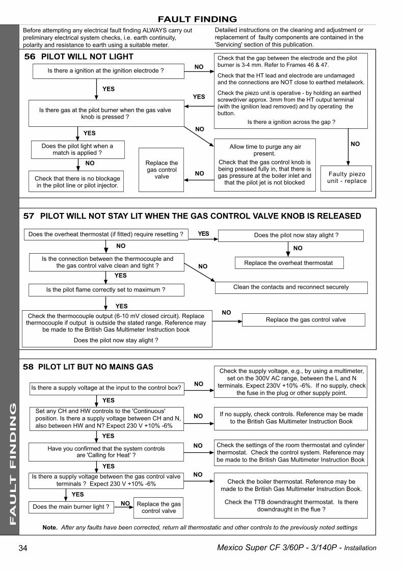
NO
NO
Is there a ignition at the ignition electrode ?
Is there gas at the pilot burner when the gas valveknob is pressed ?
56 PILOT WILL NOT LIGHT
57 PILOT WILL NOT STAY LIT WHEN THE GAS CONTROL VALVE KNOB IS RELEASED
Have you confirmed that the system controlsare 'Calling for Heat' ?
Note. After any faults have been corrected, return all thermostatic and other controls to the previously noted settings
NOIs there a supply voltage between the gas control valveterminals ? Expect 230 V +10% -6%
YES
YES
NO
Set any CH and HW controls to the 'Continuous'position. Is there a supply voltage between CH and N,also between HW and N? Expect 230 V +10% -6%
YES
Is there a supply voltage at the input to the control box?
FAULT FINDING
YESYES
NO
NO
YES
58 PILOT LIT BUT NO MAINS GAS Check the supply voltage, e.g., by using a multimeter,set on the 300V AC range, between the L and N
terminals. Expect 230V +10% -6%. If no supply, checkthe fuse in the plug or other supply point.
Check that the gap between the electrode and the pilotburner is 3-4 mm. Refer to Frames 46 & 47.
Check that the HT lead and electrode are undamagedand the connections are NOT close to earthed metalwork.
Check the piezo unit is operative - by holding an earthedscrewdriver approx. 3mm from the HT output terminal(with the ignition lead removed) and by operating thebutton.
Is there a ignition across the gap ?
NO
Faulty piezounit - replace
Allow time to purge any airpresent.
Check that the gas control knob isbeing pressed fully in, that there isgas pressure at the boiler inlet and
that the pilot jet is not blockedNO
NO
Replace thegas control
valve
If no supply, check controls. Reference may be madeto the British Gas Multimeter Instruction Book
Check the settings of the room thermostat and cylinderthermostat. Check the control system. Reference maybe made to the British Gas Multimeter Instruction Book
Does the main burner light ? Replace the gascontrol valve
Check the boiler thermostat. Reference may bemade to the British Gas Multimeter Instruction Book.
Check the TTB downdraught thermostat. Is theredowndraught in the flue ?
Before attempting any electrical fault finding ALWAYS carry outpreliminary electrical system checks, i.e. earth continuity,polarity and resistance to earth using a suitable meter.
Detailed instructions on the cleaning and adjustment orreplacement of faulty components are contained in the'Servicing' section of this publication.
Check that there is no blockagein the pilot line or pilot injector.
YES
Does the pilot light when amatch is applied ?
NO
Replace the gas control valveNOCheck the thermocouple output (6-10 mV closed circuit). Replace
thermocouple if output is outside the stated range. Reference maybe made to the British Gas Multimeter Instruction book
Does the pilot now stay alight ?
YES
YES
Is the pilot flame correctly set to maximum ?
Does the pilot now stay alight ?YES
NOIs the connection between the thermocouple and
the gas control valve clean and tight ?
NO
Clean the contacts and reconnect securely
NO Replace the overheat thermostat
Does the overheat thermostat (if fitted) require resetting ?
FA
ULT
FIN
DIN
G
35Mexico Super CF 3/60P - 3/140P - Installation
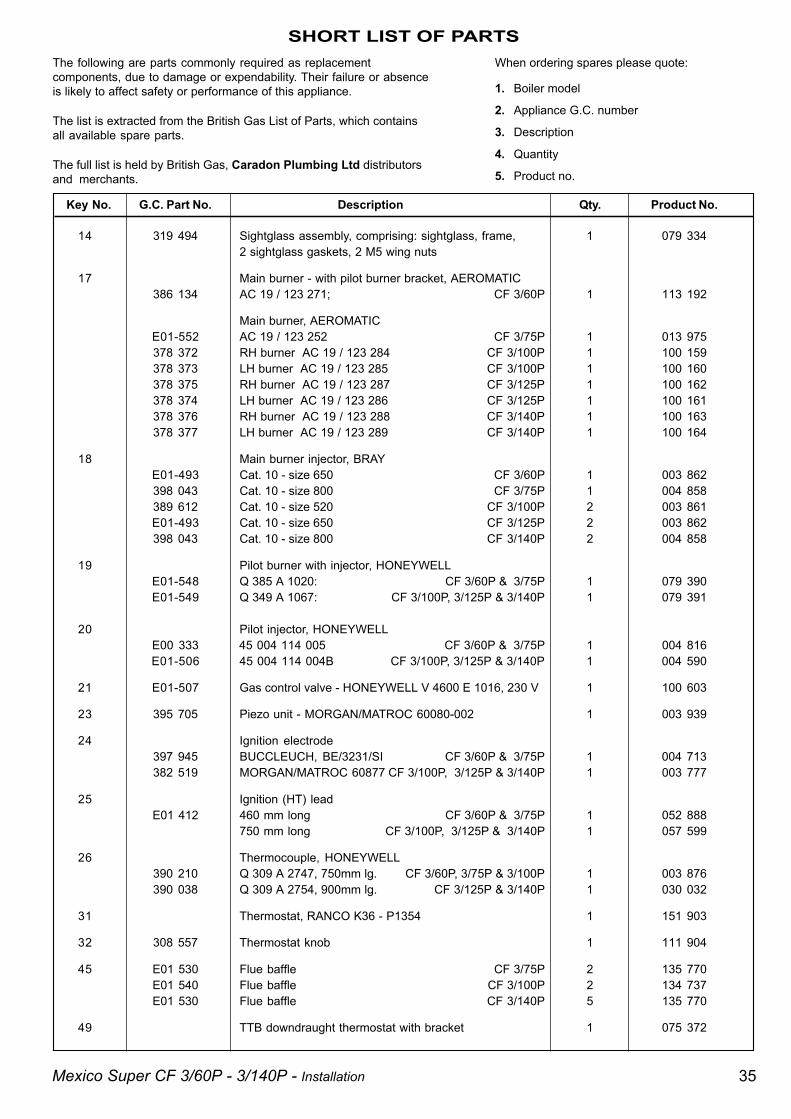
SHORT LIST OF PARTSThe following are parts commonly required as replacementcomponents, due to damage or expendability. Their failure or absenceis likely to affect safety or performance of this appliance.
The list is extracted from the British Gas List of Parts, which containsall available spare parts.
The full list is held by British Gas, Caradon Plumbing Ltd distributorsand merchants.
When ordering spares please quote:
1. Boiler model
2. Appliance G.C. number
3. Description
4. Quantity
5. Product no.
Key No. G.C. Part No. Description Qty. Product No.
14 319 494 Sightglass assembly, comprising: sightglass, frame, 1 079 3342 sightglass gaskets, 2 M5 wing nuts
17 Main burner - with pilot burner bracket, AEROMATIC386 134 AC 19 / 123 271; CF 3/60P 1 113 192
Main burner, AEROMATICE01-552 AC 19 / 123 252 CF 3/75P 1 013 975378 372 RH burner AC 19 / 123 284 CF 3/100P 1 100 159378 373 LH burner AC 19 / 123 285 CF 3/100P 1 100 160378 375 RH burner AC 19 / 123 287 CF 3/125P 1 100 162378 374 LH burner AC 19 / 123 286 CF 3/125P 1 100 161378 376 RH burner AC 19 / 123 288 CF 3/140P 1 100 163378 377 LH burner AC 19 / 123 289 CF 3/140P 1 100 164
18 Main burner injector, BRAYE01-493 Cat. 10 - size 650 CF 3/60P 1 003 862398 043 Cat. 10 - size 800 CF 3/75P 1 004 858389 612 Cat. 10 - size 520 CF 3/100P 2 003 861E01-493 Cat. 10 - size 650 CF 3/125P 2 003 862398 043 Cat. 10 - size 800 CF 3/140P 2 004 858
19 Pilot burner with injector, HONEYWELLE01-548 Q 385 A 1020: CF 3/60P & 3/75P 1 079 390E01-549 Q 349 A 1067: CF 3/100P, 3/125P & 3/140P 1 079 391
20 Pilot injector, HONEYWELLE00 333 45 004 114 005 CF 3/60P & 3/75P 1 004 816E01-506 45 004 114 004B CF 3/100P, 3/125P & 3/140P 1 004 590
21 E01-507 Gas control valve - HONEYWELL V 4600 E 1016, 230 V 1 100 603
23 395 705 Piezo unit - MORGAN/MATROC 60080-002 1 003 939
24 Ignition electrode397 945 BUCCLEUCH, BE/3231/SI CF 3/60P & 3/75P 1 004 713382 519 MORGAN/MATROC 60877 CF 3/100P, 3/125P & 3/140P 1 003 777
25 Ignition (HT) leadE01 412 460 mm long CF 3/60P & 3/75P 1 052 888
750 mm long CF 3/100P, 3/125P & 3/140P 1 057 599
26 Thermocouple, HONEYWELL390 210 Q 309 A 2747, 750mm lg. CF 3/60P, 3/75P & 3/100P 1 003 876390 038 Q 309 A 2754, 900mm lg. CF 3/125P & 3/140P 1 030 032
31 Thermostat, RANCO K36 - P1354 1 151 903
32 308 557 Thermostat knob 1 111 904
45 E01 530 Flue baffle CF 3/75P 2 135 770E01 540 Flue baffle CF 3/100P 2 134 737E01 530 Flue baffle CF 3/140P 5 135 770
49 TTB downdraught thermostat with bracket 1 075 372

36 Mexico Super CF 3/60P - 3/140P - Installation
LIST OF PARTS
59 SHORT PARTS - CF 3/60P & CF 3/75P ONLY

37Mexico Super CF 3/60P - 3/140P - Installation
LIST OF PARTS
60 SHORT PARTS - CF 3/100P, CF 3/125P & CF 3/140P ONLY
38 Mexico Super CF 3/60P - 3/140P - Installation
LIST OF PARTS
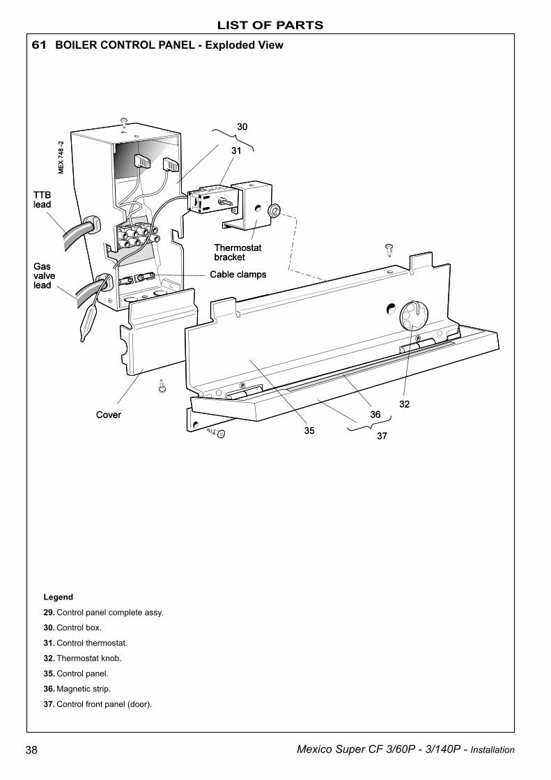
Legend
29. Control panel complete assy.
30. Control box.
31. Control thermostat.
32. Thermostat knob.
35. Control panel.
36. Magnetic strip.
37. Control front panel (door).
61 BOILER CONTROL PANEL - Exploded View

39Mexico Super CF 3/60P - 3/140P - Installation
LIST OF PARTS
62 BURNER AND CONTROLS ASSEMBLY - CF 3/60P & CF 3/75P ONLY - Exploded View
Legend
13. Front plate.
14. Sightglass.
15. Burner manifold.
16. Pilot pipe.
17. Burner.
18. Burner injector.
19. Pilot burner.
20. Pilot injector.
21. Gas valve.
22. 'O' ring.
23. Piezo unit.
24. Ignition electrode.
25. H.T. lead.
26. Thermocouple.
27. Gas service cock union.
40 Mexico Super CF 3/60P - 3/140P - Installation
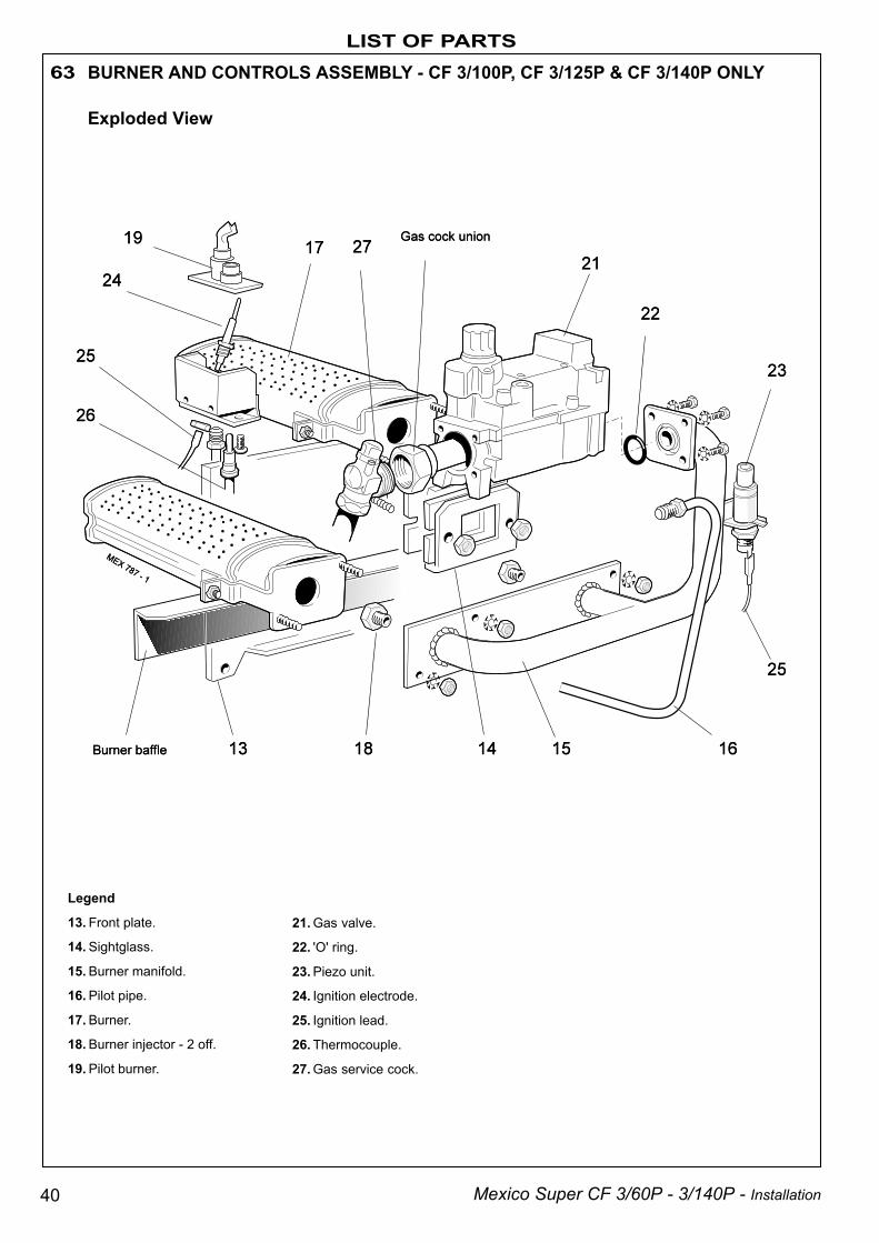
LIST OF PARTS63 BURNER AND CONTROLS ASSEMBLY - CF 3/100P, CF 3/125P & CF 3/140P ONLY
Exploded View
21. Gas valve.
22. 'O' ring.
23. Piezo unit.
24. Ignition electrode.
25. Ignition lead.
26. Thermocouple.
27. Gas service cock.
Legend
13. Front plate.
14. Sightglass.
15. Burner manifold.
16. Pilot pipe.
17. Burner.
18. Burner injector - 2 off.
19. Pilot burner.

41Mexico Super CF 3/60P - 3/140P - Installation
LIST OF PARTS
64 BOILER CASING ASSEMBLY
Legend
28. Casing complete.
29. Controls panel complete.
40. Casing side panel.
41. Casing top panel.
42. Grille panel.
43. Casing lower front panel.
46. Base plate.

42 Mexico Super CF 3/60P - 3/140P - Installation
Ideal Installer/Technical Helpline: 01482 498663
Caradon Plumbing Limited, P.O. Box 103, National Ave, Kingston upon Hull, HU5 4JN. Telephone: 01482 492 251Fax: 01482 448 858. Registration No. London 322 137. Registered Office: National Avenue, Kingston upon Hull,HU5 4JN. A subsidiary of Caradon p.l.c
Technical Training Caradon Plumbing Limitedpursues a policy of continuingimprovement in the design andperformance of its products. The rightis therefore reserved to varyspecification without notice.
September 1999 151 912 A02
The Caradon Plumbing Limited Technical Training Centreoffers a series of first class training courses for domestic,commercial and industrial heating installers, engineers andsystem specifiers.For details of courses please ring: ........... 01270 413 624
These appliances are designed for use with NaturalGas only. They have been tested and conform withthe provisions of BS. 6332 and BS. 5258.
THIS SYMBOL IS YOURASSURANCE OF QUALITY
CERTIFIED PRODUCTManufactured under a BS EN ISO 9001: 1994Quality System accepted by BSI
The code of practice for the installation,commissioning & servicing of central heating systems

43Mexico Super CF 3/60P - 3/140P - Installation
Your feedbackand your chance to win a free boiler
At Ideal we've been leaders in the design and engineering of robust andreliable boilers for over 90 years. We want to continue as leaders bylistening to your suggestions for how to improve our boilers and our service.We'll be giving away a free boiler for the five best ideas every year (to beselected by our Technical Director). Please complete this form, using extrasheets if required, and post it or fax it to us on 01482 498699.
Boiler details
Model / Size (e.g. Classic RS 230, Mexico CF 3/60 etc. Details on control panel door)
Date of Installation
Installer details
Name
Address
Post Code Telephone (Please include STD code)
How I would improve this boiler::
My general comments for Ideal:
Ideal Installer/Technical Helpline: 01482 498663
U.I.
N. 1
51 9
12 A
0
Caradon Plumbing Limited, PO Box 103, National Avenue, Kingston upon Hull, HU5 4JN. Telephone: 01482 492251 Fax: 01482 448858.
Further information
If you would like information about Ideal Boilers please complete this sheetand fax it to us on 01482 498699 or post it to Caradon Plumbing Limited,PO Box 103, National Avenue, Kingston upon Hull, HU5 4JN.
Installer details
Name
Address
Post Code Telephone (Please include STD code)
General information required
Please send me details of Ideal Training Courses.
Please arrange for a technical representative to contact me.Please arrange for me to join an Ideal factory tour.
Range guides required
The Ideal Guide: a specifier's and installer's introduction to theIdeal domestic boiler range.
The Ideal Householders Guide: to assist the installer whenpresenting to his/her customers.
Technical manuals required
The Ideal C class combi boiler
The Ideal Classic wall hung boiler
The Ideal Classic System wall hung boiler
The Ideal Classic LX Deluxe wall hung boiler
The Ideal Mexico floor standing boiler
The Ideal Minimiser heat-saving boiler
The Ideal Response combi boiler
The Ideal Response SE super efficiency combi boiler
The Ideal Systemiser SE super efficiency system boiler
The Ideal Concord high output boiler
The Ideal Buccaneer oil fired boiler
Ideal Installer/Technical Helpline: 01482 498663