Embed Size (px)
Citation preview

March 2012
IIE-UNAM WorkshopCO2 Geological Storage and EOR
MEXICAN CCS+EORDEMONSTRATION PROJECTEnvironmental Impact and Risk Analysis
Monitoring
Rodolfo LacyMario Molina Center

CO2 Sources in Mexico2009
PETACALCO
*Modificar mapa Río Escondido
Carbón II
Altamira
Tuxpan
Poza Rica
Dos Bocas
Petacalco
Manzanillo
Tula

EOR sites in theChicontepec Region
The initial proposal was to run the demonstration project in the Tuxpan Power Plant that
would be refitted to use coal as their primary source
However, due to CFE strategic decisions, it was decided to have the CCS project in the
NGCC Power Plant located at Poza Rica. The first stage is the
implementation of the Pilot Plant where the first
arrangements for EOR will be implemented
CFE TUXPANFuel oilpower plant
NGCCPrivate
power plant

CCS+EOR Proposal
It is planned that the first carbon capture project that will take place in Mexico must be a CCS+EOR form. This strategy will enable Mexico to start utilizing this low-carbon emission technology
One of the main factors that support such a project is that the CFE, PEMEX, and geological reservoirs are state-own industries and assets
*CCS+EOR. Carbon Capture and Storage + Enhance Oil Recovery

Demonstration Project
General scheme for the CCS+EOR demonstration project between CFE and PEMEX
Source: Mario Molina Center

CFE Power Plant and Poza Rica oil field

In Mexico, the Ministry of Environment and Natural Resources (SEMARNAT) requires an Environmental Impact and Risk Assessment (EIA/ERA) for the
approval of any project from the oil and electricity sectors that may cause a significant environmental or public health problem
Environmental Impact and Risk Assessment
Taking into account that a broad regulatory framework for CCS-EOR would
not be ready in the next yearsan early EIA/ERA for the demonstration
project shall provide:
HUMAN HEALTH PROTECTIONENVIRONMENTAL PROTECTION

Poza RicaTropical Weather
PRECIPITATION
Normal year 1979-2008Mean 1,186 mm Acumulated 2012
mean minimum TEMPERATURE
typical 1979-2008
oC
Mean 25oC Max 36 oC
2010 population: 193,311 people

Environmental Impact and Risk Assessment
1. Project description
2. Environmental system description
3. Environmental impacts
4. Mitigation strategies
5. Environmental projections
CCS-EOR Specifics
Information gathered by monitoring for the EIA should cover at least one year of records…
EIA Current general structure
INFORMATION TO BE INCLUDED IN ANEIA/ERA FOR CCS+EOR
• Site selection methodology• Site characteristics and safety proves
• CO2 monitoring plan• Corrective strategies
• Geological data of storage and confining zones• Wells integrity • Seismicity• Surface and groundwater quality• CO2 concentrations in soil
• Delimitation of the area that could be affected by CCS-EOR operations, modeling of CO2 plume and behavior is necessary.
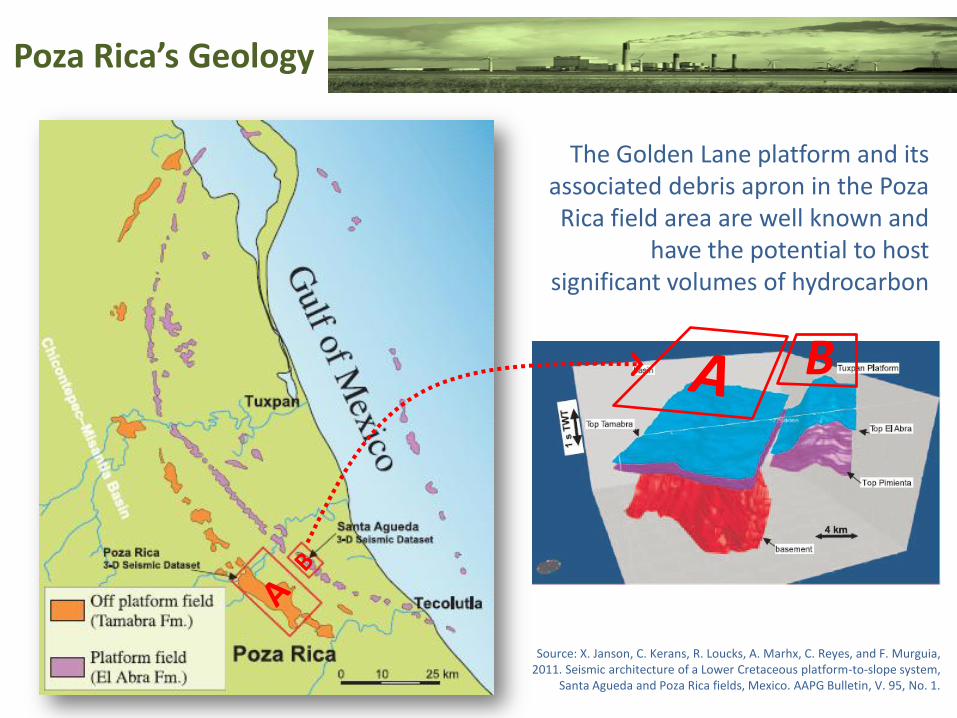
Poza Rica’s Geology
B
The Golden Lane platform and its associated debris apron in the Poza Rica field area are well known and
have the potential to host significant volumes of hydrocarbon
Source: X. Janson, C. Kerans, R. Loucks, A. Marhx, C. Reyes, and F. Murguia, 2011. Seismic architecture of a Lower Cretaceous platform-to-slope system,
Santa Agueda and Poza Rica fields, Mexico. AAPG Bulletin, V. 95, No. 1.

Poza Rica’s Geology
10203040 0 10 20 3050
coast
-1
-2
-3
-4
-5
-6
Poza Rica cityand oil wells
Kilometres
Kilo
me
tre
s
Gulf of Mexico
0
Source: X. Janson, et al.
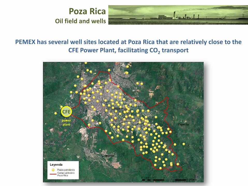
Poza Rica Oil field and wells
PEMEX has several well sites located at Poza Rica that are relatively close to the CFE Power Plant, facilitating CO2 transport
CFE
powerplant

Poza Rica RegionFaults and Fractures

Poza Rica RegionOil Fields for CO2 EOR
OIL FIELDPOSSIBLE OIL
RECOVERYMMbbl
CO2 DEMAND
MMCFD MMtons/y
Poza Rica 150-390 200-530 4.1-10.8
Tajin 160-430 220-590 4.5-12
Coapechaca 100-260 130-360 2.6-7.3
Simbología
Pozos Petroleros
Campo petrolero Poza Rica
Campos Petroleros
Oil well
Poza Rica oil field
Oil fields

Poza Rica AreaCities, Oil fields, Rivers, and
Meteorological Stations
Estaciones Meteorológicas
Radio de Influencia10 km de CampoPoza Rica
Simbología
Pozos Petroleros
Campo petrolero Poza Rica
Campos Petroleros
Cuatzintla
Papantla
Poza Rica

Environmental Impact and Risk Assessment
Source: A. Mathieson, J. Midgley, I. Wright, N. Saoula and P. Ringrose, 2010.In Salah CO2 Storage JIP: CO2 sequestration monitoring and verification
technologies applied at Krechba, Algeria. Energy Procedia 00(2010) 1063-00.
KEY RISK AND MONITORING TECHNOLOGIESIn Salah, Algeria
BP & Statoil CCS project
KEY RISK MONITORING TECHNOLOGIES
Injection Well Problems
Ongoing pressure monitoring, continuous wellhead and annual down-hole or trough casing logging
Early CO2 BreaktroughModelling, tracers, seismic imaging, observation wells, fluid sampling, wellhead and annulus monitoring
Vertical leakageSeismic imaging, microseismic, shallow aquifer monitoring, soil gas sampling, surface flux, gravity, tiltmeters, satellite imagery
Wellbore leakageAnnulus monitoring, soil gas sampling, through case logging
Old wellbore integrityAnnulus pressure monitoring and CO2 surface flux monitoringAnemometer and
open path CO2/H20 analyzerphoto: Biospherica
Near-surface seismic survey
with geophonesMASW technics
photo: USGS

Environmental Impact AssessmentMVA-Monitoring, Verification, and Accounting CO2
Source: NETL-DOE, 2009. Monitoring, Verification, and Accounting of CO2 Stored in Deep Geologic Formations.

U-tubefor CO2 measurements at the injection well
“The U-tube sampler was originally designed by Barry Freifeld and fabricated by Paul Cook, both of
Lawrence Berkeley National Laboratory for use in the CO2 sequestration pilot studies at the Frio test site in
east Texas in 2004.
The apparatus is able to collect continuous samples of reservoir fluids near in-situ temperatures and pressures and has now been used for CO2 pilot
studies at Cranfield, Mississippi (Southwest Carbon Partnership Phase 3) and Otway in Australia.”
Source: Freifeld, Barry M., Trautz, Robert C., Kharaka, Yousif K., Phelps, Tommy J., Myer, Larry R., Hovorka, Susan D., et al.(2005). The U-Tube: A Novel System for Acquiring Borehole Fluid Samples from a Deep Geologic CO2 Sequestration Experiment. Lawrence Berkeley National Laboratory: Lawrence Berkeley National Laboratory. LBNL Paper LBNL-57317. Retrieved from: http://escholarship.org/uc/item/5j43009c

Environmental Impact and Risk Assessment
Monitoring, Verification, and Accounting Dimensions
SOURCES
ENVIRONMENT
PROJECT phases

FUENTE: Centro Mario Molina, 2010
Environmental Impact and Risk Assessment
CO2
CO2
CO2
CO2 storage
CO2
Geological faultpresence
CO2
GW level
Transportation of presurized CO2
CO2 plume
CO2
injection
Surface watermonitoring
Soil gas monitoring
Standards for CO2
transport
Standards for site selection and CO2 injection andfor monitoring of injected CO2 and other chemical species
Clean Air Actstandards

*The CO2 capture system requires an influent with NOx and SOx concentrations within the 10-20 ppm range
air emissions from the stackCFE
Levels of pollutant emissions expected from one unit at a coal or petcoke power generation plant WITH
and WITHOUT CO2 capture system*
No capture
Par
ticl
es(m
g/N
m3)
Capture
NOM-085 for NOx (110 ppmv)
NOM-085 for SOx (550 ppmv)
NOM-085 for particles (250 mg/m3)
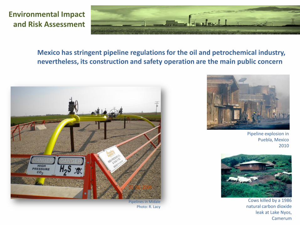
Environmental Impact and Risk Assessment
Mexico has stringent pipeline regulations for the oil and petrochemical industry, nevertheless, its construction and safety operation are the main public concern
Pipelines in MidalePhoto: R. Lacy
Cows killed by a 1986 natural carbon dioxide
leak at Lake Nyos, Camerum
Pipeline explosion in Puebla, Mexico
2010

ENVIRONMENTALMAV for CO2 stored
SOURCE: Ellaborated with ilustrations from British Geological Survey & Schlumberger Water Services
23
corrosion effect
Impermeable layerCO2CO2CO2
CO2
Difussion
CO2 pure phase
CO2 Plume
Difussion
CO2 en lowpermeability stratus
CO2 PlumeDifussion
CO2 dissolved in groundwater
Seismic studies
Groundwatermonitoring
Underwatermonitoring
Soil gas monitoring
CO2 Plume Vadose zone
Monitoreo of aerosols(CO2 leak detection)
Monitoringequipment
Permanentmonitoring of gas in soil and surface
InSAR(Satellital images)

Radar Remote Sensing for CO2 monitoring

Environmental Impact AssessmentMVA-Monitoring, Verification, and Accounting CO2
Source: NETL-DOE, 2009. Monitoring, Verification, and Accounting of CO2 Stored in Deep Geologic Formations.
Preparing fluorescine
solution to be injected in the
Frio Brine research project,
Texas USA
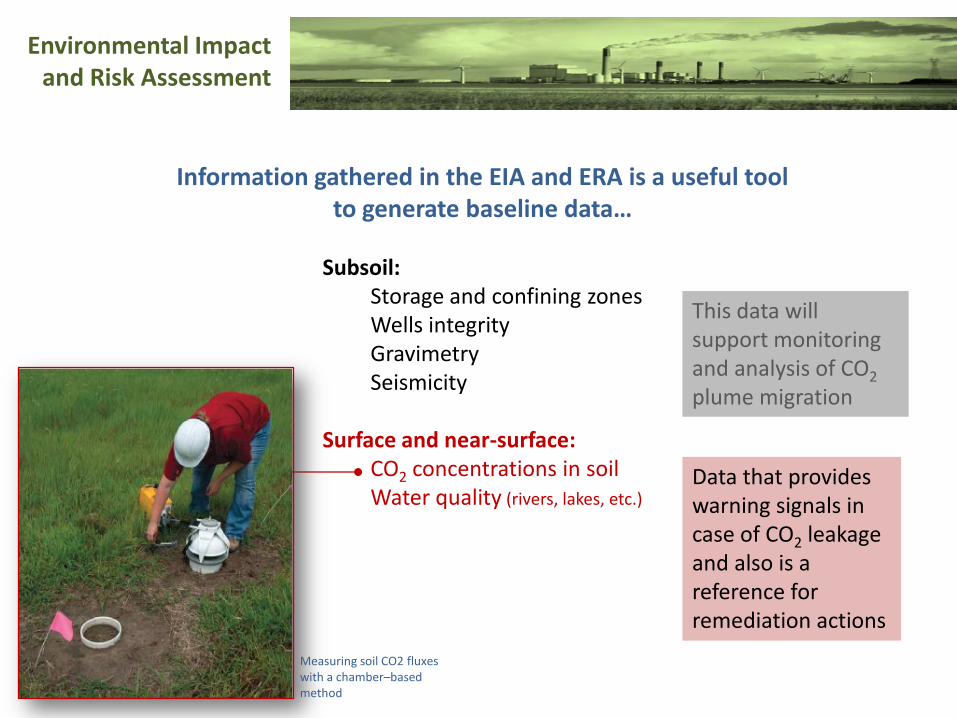
Environmental Impact and Risk Assessment
Information gathered in the EIA and ERA is a useful toolto generate baseline data…
Subsoil:Storage and confining zonesWells integrityGravimetrySeismicity
Surface and near-surface: CO2 concentrations in soilWater quality (rivers, lakes, etc.)
This data will support monitoring and analysis of CO2
plume migration
Data that provides warning signals in case of CO2 leakage and also is a reference for remediation actions
Measuring soil CO2 fluxes with a chamber–based method

THANK YOU


![BGD001B Retro Digital 100M-WR (Black & Pink) 12 EOR - Mist ... · Mist Digital 100M-WR [Nude & Rosegold] 222 EOR - - BG002A Diva Bronze 190 EOR - BG002B Diva Silver 133 EOR - BG003C](https://img.dokumen.tips/doc/110x75/5e7cf3eec367ea52344b7489/bgd001b-retro-digital-100m-wr-black-pink-12-eor-mist-mist-digital.jpg)